

Page 1
Sigma 1 - Axis Servo Motor and Cables - Troubleshooting Guide
LAST UPDATED: 12/21/2018
Sigma 1 - Axis Servo Motor and Cables - Troubleshooting Guide
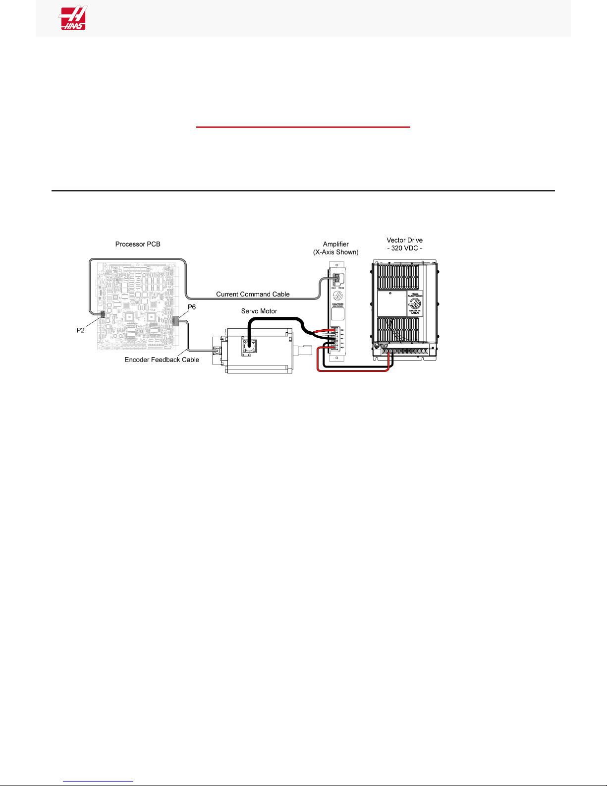
Introduction
Press [POWER OFF]. Set the main circuit breaker to the OFF position. Wait until the high voltage LED on the vector drive
is completely off before disconnecting any cables.
Page 1 of 7 pages
Page 2

Sigma 1 - Axis Servo Motor and Cables - Troubleshooting Guide
Symptom Table
Page 2 of 7 pages
Page 3

Sigma 1 - Axis Servo Motor and Cables - Troubleshooting Guide
SYMPTOM PROBABLE CAUSE CORRECTIVE ACTION
Check the corresponding amplifier assembly.
Refer to Servo Amplifier - Troubleshooting Guide to
troubleshoot the amplifier.
Inspect the cables and connectors. Refer to the Power
Cable section below.
Alarm 161 - 164 AXIS DRIVE
FAULT.
Alarm 993 AMPLIFIER SHORT
CIRCUIT
Faulty servo amplifier.
Faulty power cable.
Alarm 103 - 105, 270,
709 AXIS SERVO ERROR TOO
LARGE.
Faulty servo motor.
Faulty encoder cable/
connection or faulty
encoder.
The axis motor brake, is not
disengaging when servos
are enabled.
The axis ballscrew is
damaged.
Classic Haas Control Only The machine parameters are
not correct.
Check the corresponding servo motor. Refer to Servo
Motor section below.
Inspect the cables and connectors. Refer to the Main
Processor/Encoder Cable section below. Check the
encoder steps/revolution versus and ball screw pitch
and verify the encoder counts are accurate per each
rotation.
See the Motor Brake section below:
Check the corresponding axis ballscrew.
Refer to Ballscrew - Troubleshooting Guide to
troubleshoot the ballscrew.
Make sure you have the correct parameters for the type
of axis motor.
1. Determine if machine has Sigma-1 or
Sigma-5 motors.
Note: The Sigma-5 axis motor have a
push-lock connector for the encoder
plug.
Alarm 103 - 105 AXIS SERVO
ERROR TOO LARGE, during
the zero return process. The
axis zero returns in the wrong
direction.
Alarm 135 - 137 AXIS MOTOR
OVERHEAT.
The home sensor is being
made during the zero return
process causing the axis to
zero return in the opposite
direction.
Faulty encoder cable/
connection or faulty
encoder.
The Mocon/Maincon PCB
axis channel is defective.
2. Run parameter checker and select either
Sigma-1 or Sigma-5 option.
Check the axis home switch to make sure there are no
metal chips on top of the sensor.
Inspect the cables and connectors. Refer to the Main
Processor/Encoder Cable section below. Check the
encoder steps/revolution versus and ball screw pitch
and verify the encoder counts are accurate per each
rotation..
Swap the Encoder/Drive channels with another axis, if
the alarm stays with the encoder/drive channel then the
Mocon/Maincon PCB is defective.
Page 3 of 7 pages
Page 4

Sigma 1 - Axis Servo Motor and Cables - Troubleshooting Guide
Alarm 139 - 142 190,
273 MOTOR Z FAULT.
Alarm 153 - 156 Z CHANNEL
MISSING
Alarm 182 - 185, 194,
278 AXIS ENCODER CABLE
FAULT.
Alarm 217, 218, 219 AXIS
PHASE ERROR
Alarm 224 - 228 AXIS
TRANSITION FAULT
The low-volt-power-supply
is defective.
The parameter OVER TEMP
NC bit 14 for the axis is
incorrect.
Faulty encoder cable or
connection.
Faulty encoder on servo
motor.
Check the +5V / +12V / -12V DC voltages going to the
Mocon/ Maincon PCB.
Make sure this parameter bit is set correctly. This is
normally a 1.
Inspect the cables and connectors. Refer to the Main
Processor/Encoder Cable section below.
Check the motor for coolant contamination. Check the
encoder steps/revolution versus and ball screw pitch
and verify the encoder counts are accurate per each
rotation.
Power Cable
Corrective Action:
Make sure the cables are connected correctly to the corresponding amplifier. Inspect the connector at the motor. Look for
loose connections or contamination.
Look for signs of damage or stiffness on the cable. Disconnect the power cable from the amplifier and motor. Measure the
resistance from leg to leg, and from leg to ground. Make sure the measurements result in an open connection. Check
each leg from one end of the cable to the corresponding leg on the other end of the cable for continuity. If there is an open
connection, there is a problem with the cable.
Page 4 of 7 pages
Page 5
Sigma 1 - Axis Servo Motor and Cables - Troubleshooting Guide
Servo Motor
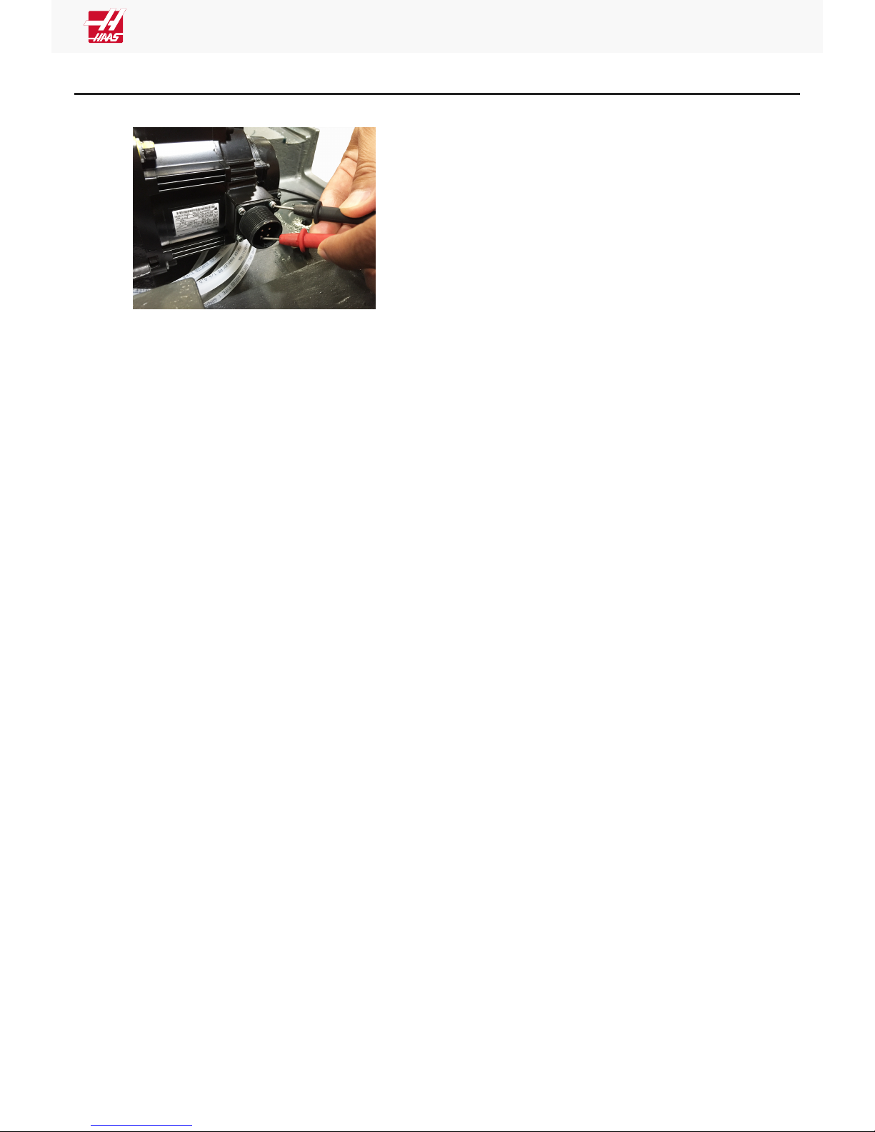
Corrective Action:
Make sure the motor's connectors are not
contaminated. Disconnect and inspect the power
cable connector at the motor. Make sure that there
is no coolant contamination. Coolant contamination
can generate drive fault alarms and damage the
amplifier. Measure the resistance from the pins
labeled A, B and C at the motor connector to
chassis ground.
• The reading must show an open circuit.
• If the reading does not show an open
circuit, the servo motor is at fault.
Page 5 of 7 pages
Page 6
Sigma 1 - Axis Servo Motor and Cables - Troubleshooting Guide
Main Processor/Encoder Cable/Encoder
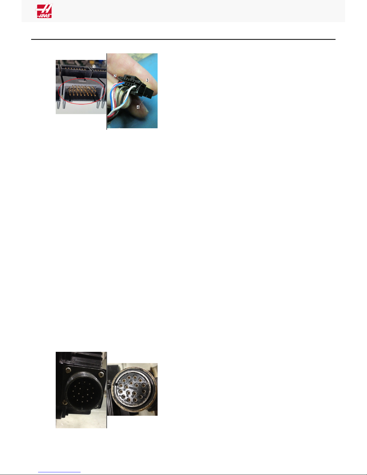
Corrective Action - Main Processor/Cable:
Examine the connector [1] on the Maincon or
MOCON PCB. Make sure it is not damaged.
Examine the cable. Look for signs of damage or
stiffness. The connector [4] has two housings [2,3]
for the cable pins.
Measure the resistance on the encoder cable from
leg to leg, and from leg to ground. Make sure each
measurement results in an open connection.
Make sure the cable is firmly connected at both
ends. Reseat both connections. Make sure the
cable is installed in the correct connector at the
Maincon or MOCON PCB.
Corrective Action - Servo Motor Encoder:
Check the encoder steps/revolution in the
configuration file. Jog the axis and based on the
distance the ball screw travels per revolution (ball
screw pitch), verify the encoder counts are accurate
per each rotation. View the diagnostic>axis page as
you jog the axis. The raw encoder count will show
you how many encoder steps have been counted.
The z axis channel will also show how many steps
have been counted, but will reset each time the zpulse is passed. The z-pulse is the encoder zero
point, so it will reset every time the encoder does
one revolution. Based on this information, you will
know if the encoder works if the correct amount of
steps per revolution are counted each time you jog
the axis the distance of the ball screw pitch length.
If the numbers do not match up, you have a
problem.
Page 6 of 7 pages
Page 7
Sigma 1 - Axis Servo Motor and Cables - Troubleshooting Guide
Motor Brake
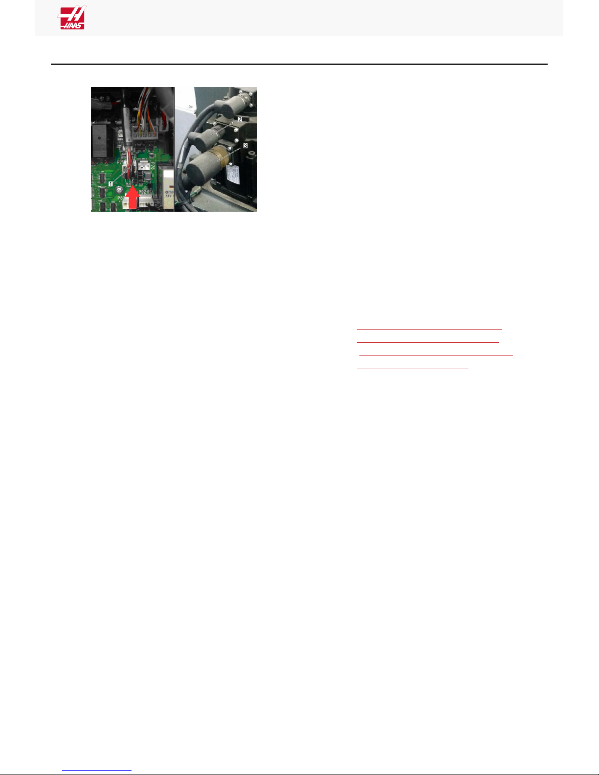
Corrective Action:
Reseat the the connection for connectors P79 or
P78 [1] on the I/O PCB.
Measure the voltage across the red and black
cables.
Press [EMERGENCY STOP]. There should be no
voltage.
Press [RESET] to clear the alarms. The voltage
should be between 20-30 VDC.
Examine the connection at the motor's brake [2]
and power connectors [3] for contamination. Reseat
the connections.
If no voltage is present, refer to:
• NEXT GENERATION CONTROL - I/O
PCB - TROUBLESHOOTING GUIDE
• I/O PCB -TROUBLESHOOTING GUIDE
(CLASSIC HAAS CONTROL)
Page 7 of 7 pages
 Loading...