

Page 1
Mill Operator’s Manual
HAAS AUTOMATION INC. • 2800 STURGIS ROAD • OXNARD, CA 93030
TEL. 888-817-4227 FAX. 805-278-8561
96-8000 revR
JUNE 2007
www.HaasCNC.com
Page 2

Warranty Certificate
Covering Haas Automation, Inc., CNC Equipment
Effective January 1, 2003
LIMITED WARRANTY COVERAGE
All new Haas mills are warranted exclusively by the Haas Automation’s ("Manufacturer") limited warranty as follows:
Each Haas CNC machine ("Machine") and its components ("Components") (except those listed below under limits and
exclusions) is warranted against defects in material and workmanship for a period of one (1) year
and Mini-Mills, which are six (6) months) from the date of purchase, which is the date that a machine is installed at the
end user. The foregoing is a limited warranty and it is the only warranty by manufacturer. Manufacturer disclaims all other
warranties, express or implied, including but not limited to all warranties of merchantability and fitness for a particular
purpose.
REPAIR OR REPLACEMENT ONLY: MANUF ACTURER'S LIABILITY UNDER THIS AGREEMENT SHALL BE LIMITED T O
REP AIRING OR REPLACING , A T THE DISCRETION OF MANUF ACTURER, P ARTS, OR COMPONENTS.
An additional warranty extension may be purchased from your authorized Haas distributor.
LIMITS and EXCLUSIONS of WARRANTY
Except as provided above, buyer agrees that all warranties express or implied, as to any matter whatsoever, including but
not limited to warranties of merchantability and fitness for a particular purpose are excluded.
Components subject to wear during normal use and over time such as paint, window finish and condition, light bulbs,
seals, chip removal system, etc., are excluded from this warranty.
Factory-specified maintenance procedures must be adhered to and recorded in order to maintain this warranty.
This warranty is void if the machine is subjected to mishandling, misuse, neglect, accident, improper installation, improper
maintenance, or improper operation or application, or if the machine was improperly repaired or serviced by the customer
or by an unauthorized service technician. Warranty service or repair service is available from the authorized Haas distributor.
Without limiting the generality of any of the exclusions or limitations described in other paragraphs, manufacturer's warranty does not include any warranty that the machine or components will meet buyer's
production specifications or other requirements or that operation of the machine and components will be uninterrupted or error-free. Manufacturer assumes no responsibility with respect to the use of the
Machine and Components by Buyer, and manufacturer shall not incur any liability or Seller to Buyer for any failure in design, production, operation, performance or otherwise of the Machine or
Components other than repair or replacement of same as set forth in the Limited Warranty above. Manufacturer is not responsible for any damage to parts, machines, business premises or other property
of Buyer,or for any other incidental or consequential damages that may be caused by a malfunction of the Machine or Components.
(except Tooroom Mills
LIMIT ATION OF LIABILITY AND DAMAGES: MANUF ACTURER IS NOT LIABLE TO BUYER, SELLER OR ANY CUSTOMER OF
BUYER FOR LOSS OF PROFITS, LOST DA T A, LOST PRODUCTS, LOSS OF REVENUE, LOSS OF USE, COST OF DOWN
TIME, BUSINESS GOOD WILL, OR ANY OTHER INCIDENT AL OR CONSEQUENTIAL DAMAGE, WHETHER IN AN ACTION IN
CONTRACT OR TORT, ARISING OUT OF OR RELA TED T O THE MACHINE OR COMPONENTS, OTHER PRODUCTS OR
SERVICES PROVIDED BY MANUF ACTURER OR SELLER, OR THE F AILURE OF PAR TS OR PRODUCTS MADE BY USING
THE MACHINE OR COMPONENTS, EVEN IF MANUFACTURER OR SELLER HAS BEEN ADVISED OF THE POSSIBILITY OF
SUCH DAMAGES. MANUFACTURER'S LIABILITY FOR DAMAGES FOR ANY CAUSE WHA TSOEVER SHALL BE LIMITED TO
REP AIR OR REPLACEMENT , A T THE DISCRETION OF MANUF ACTURER, OF THE DEFECTIVE P AR TS, COMPONENTS OR
MACHINE.
Buyer has accepted this restriction on its right to recover incidental or consequential damages as part of its bargain with
Seller. Buyer realizes and acknowledges that the price of the equipment would be higher if Seller or Manufacturer were
required to be responsible for incidental or consequential damages, or punitive damages.
This Warranty Certificate supersedes any and all other agreements, either oral or in this writing, between the parties hereto with respect to the warranties, limitations of liability and/or damages regarding
the Machine or Components, and contains all of the covenants and agreements between the parties with respect to such warranties, liability limitations and/or damages. Each party to this Warranty
Certificate acknowledges that no representations, inducements, promises, or agreements, orally or otherwise, have been made by any party , or anyone acting on behalf of any party, which are not embodied
herein regarding such warranties, liability limitations and/or damages, and that no other agreement, statement, or promise not contained in this Warranty Certificate shall be valid or binding regarding
such warranties, liability limitations and damages.
TRANSFERABILITY
This warranty is transferrable from the original end-user to another party if the machine is sold via private sale before the
end of the warranty period.
Haas Automation, Inc. 2800 S turgis Road, Oxnard, CA 93030-8933 Phone: (805) 278-1800 F AX: (805) 278-8561
96-8000 rev R June 2007
T able Of Contents
I
Page 3

Warranty Registration
Certificate
LIMITED WARRANTY COVERAGE
All new Haas mills are warranted exclusively by the Haas Automation’ s ("Manufacturer") limited warranty as follows:
Each Haas CNC machine ("Machine") and its components ("Components") (except those listed below under limits
and exclusions) is warranted against defects in material and workmanship for a period of one (1) year (except
T ooroom Mills and Mini-Mills, which are six (6) months) from the date of purchase, which is the date that a machine
is installed at the end user . The foregoing is a limited warranty and it is the only warranty by manufacturer . Manufacturer disclaims all other warranties, express or implied, including but not limited to all warranties of merchantability
and fitness for a particular purpose.
REPAIR OR REPLACEMENT ONL Y: MANUFACTURER'S LIABILITY UNDER THIS AGREEMENT SHALL
BE LIMITED TO REP AIRING OR REPLACING , A T THE DISCRETION OF MANUFACTURER, P ARTS, OR
COMPONENTS.
An additional warranty extension may be purchased from your authorized Haas distributor.
LIMITS and EXCLUSIONS of W ARRANTY
Except as provided above, buyer agrees that all warranties express or implied, as to any matter whatsoever , including but not limited to warranties of merchantability and fitness for a particular purpose are excluded.
Components subject to wear during normal use and over time such as paint, window finish and condition, light bulbs,
seals, chip removal system, etc., are excluded from this warranty .
Factory-specified maintenance procedures must be adhered to and re corded in order to maintain this warranty .
This warranty is void if the machine is subjected to mishandling, misuse, neglect, accident, improper installation,
improper maintenance, or improper operation or application, or if the machine was improperly repaired or serviced by
the customer or by an unauthorized service technician. Warranty service or repair service is available from the
authorized Haas distributor.
Without limiting the generality of any of the exclusions or limitations described in other paragraphs, manufacturer's
warranty does not include any warranty that the machine or components will meet buyer's production specifications
or other requirements or that operation of the machine and components will be uninterrupted or error-free. Manufacturer assumes no responsibility with respect to the use of the Machine and Components by Buyer , and manufacturer
shall not incur any liability or Seller to Buyer for any failure in design, production, operation, performance or otherwise of the Machine or Components other than repair or replacement of same as set forth in the Limited Warranty
above. Manufacturer is not responsible for any damage to parts, machines, business premises or other property of
Buyer, or for any other incidental or consequential damages that may be caused by a malfunction of the Machine or
Components.
LIMITATION OF LIABILITY AND DAMAGES: MANUFACTURER IS NOT LIABLE TO BUYER, SELLER
OR ANY CUSTOMER OF BUYER FOR LOSS OF PROFITS, LOST DA T A, LOST PRODUCTS, LOSS OF REVENUE, LOSS OF USE, COST OF DOWN TIME, BUSINESS GOOD WILL, OR ANY OTHER INCIDENT AL OR
CONSEQUENTIAL DAMAGE, WHETHER IN AN ACTION IN CONTRACT OR TORT, ARISING OUT OF OR RELA TED TO THE MACHINE OR COMPONENTS, OTHER PRODUCTS OR SERVICES PROVIDED BY MANUFACTURER OR SELLER, OR THE F AILURE OF P ARTS OR PRODUCTS MADE BY USING THE MACHINE OR COMPONENTS, EVEN IF MANUFACTURER OR SELLER HAS BEEN ADVISED OF THE POSSIBILITY OF SUCH
DAMAGES. MANUFACTURER'S LIABILITY FOR DAMAGES FOR ANY CAUSE WHATSOEVER SHALL BE
LIMITED TO REP AIR OR REPLACEMENT , A T THE DISCRETION OF MANUF ACTURER, OF THE DEFECTIVE
P ARTS, COMPONENTS OR MACHINE.
II
T able Of Contents
96-8000 rev R June 2007
Page 4

Buyer has accepted this restriction on its right to recover incidental or consequential damages as part of its
bargain with Seller. Buyer realizes and acknowledges that the price of the equipment would be higher if Seller or
Manufacturer were required to be responsible for incidental or consequential damages, or punitive damages.
This Warranty Certificate supersedes any and all other agreements, either oral or in this writing, between the
parties hereto with respect to the warranties, limitations of liability and/or damages regarding the Machine or
Components, and contains all of the covenants and agreements between the parties with respect to such
warranties, liability limitations and/or damages. Each party to this Warranty Certificate acknowledges that no
representations, inducements, promises, or agreements, orally or otherwise, have been made by any p arty , or
anyone acting on behalf of any party , which are not embodied herein regarding such warranties, liability limitations and/or damages, and that no other agreement, statement, or promise not contained in this Warranty
Certificate shall be valid or binding regarding such warranties, liability limitations and damages.
TRANSFERABILITY
This warranty is transferrable from the original end-user to another party if the machine is sold via private sale
before the end of the warranty period.
Should you have a problem with your machine, please consult your operator's manual first. If this does not
resolve the problem, call your authorized Haas distributor. As a final solution, call Haas directly at the number
indicated below.
Haas Automation, Inc.
2800 Sturgis Road
Oxnard, California 93030-8933 USA
Phone: (805) 278-1800
FAX: (805) 278-8561
In order to record the end-user of this machine for updates and for product safety notices, we must have the
machine registration returned immediately . Please fill out completely and mail to the above address to A TTENTION
(VF-1, GR-510, VF-6, etc. — whichever is applicable) REGISTRA TIONS. Please include a copy of your invoice
to validate your warranty date and to cover any additional options you may have purchased.
Company Name:Company Name:
Company Name:
Company Name:Company Name:
Address:Address:
Address:
Address:Address:
______________________________________________________________________________________________________________________________________________________________________________________
___________________________________________________________________________________________
______________________________________________________________________________________________________________________________________________________________________________________
______________________________________________________________________________________________________________________________________________________________________________________
___________________________________________________________________________________________
______________________________________________________________________________________________________________________________________________________________________________________
Dealer:Dealer:
Dealer:
Dealer:Dealer:
Model No.Model No.
Model No.
Model No.Model No.
Telephone: (Telephone: (
Telephone: (
Telephone: (Telephone: (
This machine is equipped with an electronically-recorded serial number that cannot be altered. This is done to
protect you in case of theft and to track machines when sold to other owners. After approximately 800 hours of use,
the machine will automatically shut down if it has not been electronically unlocked by the Haas Factory Outlet. T o
unlock the machine, we must have the above registration with the serial number. Y ou will receive a number from the
Haas Factory Outlet that you will write in over the serial number on the setting page (#26). If, for any reason, the
serial number of the machine is erased in memory, the machine will revert back to a 200 hour limit for your
protection.
__________________________________________________________________________________________________________________________________________________________________
_________________________________________________________________________________
__________________________________________________________________________________________________________________________________________________________________
________________________________________________________________________________
________________________________________
________________________________________________________________________________
::
________________________________________________________________________
:
____________________________________
::
________________________________________________________________________
IMPORIMPOR
IMPOR
IMPORIMPOR
__________________________________________________________
_____________________________
__________________________________________________________
______
) )
___
______
TT
T
TT
______________________________________________________
)
___________________________
) )
______________________________________________________
ANT NOANT NO
ANT NO
ANT NOANT NO
TICE!!! PLEASE READ IMMEDIATICE!!! PLEASE READ IMMEDIA
TICE!!! PLEASE READ IMMEDIA
TICE!!! PLEASE READ IMMEDIATICE!!! PLEASE READ IMMEDIA
Contact Name:Contact Name:
Contact Name:
Contact Name:Contact Name:
Date Installed:Date Installed:
Date Installed:
Date Installed:Date Installed:
Serial Number:Serial Number:
Serial Number:
Serial Number:Serial Number:
FAX: (FAX: (
FAX: (
FAX: (FAX: (
__________
_____
__________
))
______________________________________________________
)
___________________________
))
______________________________________________________
________________________________________________
________________________
________________________________________________
________________________________________________
________________________
________________________________________________
________________________________________________
________________________
________________________________________________
TELTEL
Y!!!Y!!!
TEL
Y!!!
TELTEL
Y!!!Y!!!
96-8000 rev R June 2007
T able Of Contents
III
Page 5
Customer Satisfaction Procedure
Dear Haas customer,
Your complete satisfaction and goodwill are of the utmost importance to both Haas Automation, Inc.,
and the Haas distributor where you purchased your equipment. Normally, any concerns you may have
about the sales transaction or the operation of your equipment will be rapidly resolved by your
distributor.
However, if your concerns are not resolved to your complete satisfaction, and you have discussed your
concerns with a member of the dealership’s management, the General Manager or the dealership’s owner
directly, please do the following:
Contact Haas Automation’s Customer Service Center by calling 800-331-6746 and ask for the Customer
Service Department. So that we may resolve your concerns as quickly as possible, please have the
following information available when you call:
• Your name, company name, address and phone number
• The machine model and serial number
• The dealership name, and the name of your latest contact at the dealership
• The nature of your concern
If you wish to write Haas Automation, please use this address:
Haas Automation, Inc.
2800 Sturgis Road
Oxnard, CA 93030
Att: Customer Satisfaction Manager
e-mail: Service@HaasCNC.com
Once you contact the Haas Automation Customer Service Center, we will make every effort to work
directly with you and your distributor to quickly resolve your concerns. At Haas Automation, we know
that a good Customer-Distributor-Manufacturer relationship will help ensure continued success for all
concerned.
Customer Feedback
If you have any concerns or questions in regards to the Haas Operator’s manual, please contact us via our
E-mail, pubs@haascnc.com. We look forward to any suggestions you may have.
Certification
All Haas CNC machine tools carry the ETL Listed
mark, certifying that they conform to the NFP A 79
Electrical Standard for Industrial Machinery and
the Canadian equivalent, CAN/CSA C22.2 No. 73.
The ETL Listed and cETL Listed marks are awarded
to products that have successfully undergone
testing by Intertek Testing Services (ITS), an
alternative to Underwriters’ Laboratories.
The ISO 9001:2000 certification from TUV
Management Service (an ISO registrar) serves as
an impartial appraisal of Haas Automation’s quality
management system. This achievement affirms
Haas Automation’ s conformance with the standards
set forth by the International Organization for
Standardization, and acknowledges the Haas
commitment to meeting the needs and requirements
of its customers in the global marketplace.
IV
T able Of Contents
96-8000 rev R June 2007
Page 6

The Information contained in this manual is constantly being updated.
The latest updates, and other helpful information is available online as a
free download in .pdf format (go to
www .HaasCNC.com and click on
“Manual Updates” under the “Customer Services” drop-down menu in
the navigation bar).
T able of Contents
SAFETY ................................................................................................................................................................... 4
OPERA TION ............................................................................................................................................................ 9
PENDANT KEYBOARD INTRODUCTION ............................................................................................................. 11
FUNCTION KEYS ........................................................................................................................................ 12
JOG KEYS ................................................................................................................................................ 12
OVERRIDE KEYS ....................................................................................................................................... 13
DISPLA Y KEYS ........................................................................................................................................... 14
CURSOR KEYS .......................................................................................................................................... 15
ALPHA KEYS ............................................................................................................................................. 15
MODE KEYS ............................................................................................................................................. 16
NUMERIC KEYS ......................................................................................................................................... 17
POSITION DISPLAYS .................................................................................................................................... 17
OFFSETS DISPLAY ...................................................................................................................................... 18
CURRENT COMMANDS DISPLAY ..................................................................................................................... 18
ALARMS / MESSAGES DISPLAY ...................................................................................................................... 19
SETTING / GRAPHIC DISPLAY FUNCTION ......................................................................................................... 20
DATE AND TIME ......................................................................................................................................... 21
SCREEN SAVER......................................................................................................................................... 21
HELP / CALCULATOR FUNCTION .................................................................................................................... 21
SPINDLE WARM-UP PROGRAM ..................................................................................................................... 24
RUN-STOP-JOG-CONTINUE.......................................................................................................................... 24
COOLANT LEVEL GAUGE ............................................................................................................................. 25
OPTIONS .................................................................................................................................................. 25
RJH-E SCREENS ............................................................................................................................... ....... 28
PROGRAMMING ................................................................................................................................................... 31
MACHINE POWER-UP ................................................................................................................................. 31
PROGRAMMING INTRODUCTION ..................................................................................................................... 31
ALPHABETICAL ADDRESS CODES .................................................................................................................. 38
PART SETUP............................................................................................................................................. 38
TOOLING ................................................................................................................................................. 39
TOOL CHANGER ........................................................................................................................................ 40
JOG MODE .............................................................................................................................................. 48
PALLET CHANGER (EC-SERIES AND MDC-500) ............................................................................................. 56
TIPS AND TRICKS ...................................................................................................................................... 62
96-8000 rev R June 2007
T able Of Contents
V
Page 7

INTUITIVE PROGRAMMING SYSTEM (IPS)......................................................................................................... 65
NTRODUCTION .......................................................................................................................................... 65
I
AUTOMATIC MODE ...................................................................................................................................... 65
SYSTEM MODE .......................................................................................................................................... 65
SUBROUTINES ..................................................................................................................................................... 68
L
OCAL SUBROUTINES ................................................................................................................................68
SUBROUTINE CANNED CYCLE EXAMPLE ......................................................................................................... 69
SUBROUTINES WITH MULTIPLE FIXTURES ...................................................................................................... 69
ADV ANCED EDITOR ............................................................................................................................................. 70
THE PROGRAM MENU ................................................................................................................................70
THE EDIT MENU ....................................................................................................................................... 71
THE SEARCH MENU .................................................................................................................................. 71
THE MODIFY MENU ................................................................................................................................... 71
THE I/O MENU......................................................................................................................................... 72
THE F1: HELP MENU ................................................................................................................................72
ADVANCED EDITOR SHORTCUTS ................................................................................................................... 73
QUICK CODE ........................................................................................................................................................ 74
VISUAL QUICK CODE ................................................................................................................................. 79
CUTTER COMPENSATION.................................................................................................................................... 80
ENTRY AND EXIT FROM CUTTER COMPENSATION ............................................................................................... 81
FEED ADJUSTMENTS IN CUTTER COMPENSATION .............................................................................................. 81
MACROS ............................................................................................................................................................... 83
INTRODUCTION .......................................................................................................................................... 83
OPERATION NOTES ..................................................................................................................................... 84
SYSTEM VARIABLES IN-DEPTH ...................................................................................................................... 89
VARIABLE USAGE ....................................................................................................................................... 93
ADDRESS SUBSTITUTION ............................................................................................................................ 94
G65 MACRO SUBROUTINE CALL ................................................................................................................101
COMMUNICATION WITH EXTERNAL DEVICES - DPRNT[ ] .................................................................................102
FANUC-STYLE MACRO FEATURES NOT INCLUDED IN HAAS CNC CONTROL .........................................................104
4TH AND 5TH AXIS PROGRAMMING .................................................................................................................105
CREATING FIVE-AXIS PROGRAMS .................................................................................................................105
INSTALLING AN OPTIONAL FOURTH AXIS ........................................................................................................107
INSTALLING AN OPTIONAL FIFTH AXIS ...........................................................................................................108
AUXILIARY AXIS .......................................................................................................................................108
DISABLEING THE AXES ..............................................................................................................................109
G CODES (PREPARA T ORY FUNCTIONS)............................................................................................................ 111
M CODES (MISCELLANEOUS FUNCTIONS) .......................................................................................................167
SETTINGS............................................................................................................................................................175
MAINTENANCE ....................................................................................................................................................193
INDEX...................................................................................................................................................................207
This manual and all of its contents are copyright protected 2007, and may not be reproduced without written
permission from Haas Automation, Inc.
VI
T able Of Contents
96-8000 rev R June 2007
Page 8
HAAS SAFETY PROCEDURES
T HINK SAFETY!
DON’T GET CAUGHT UP
IN YOUR WORK
All milling machines contain hazards from rotating
parts, belts and pulleys, high voltage electricity,
noise, and compressed air. When using CNC
machines and their components, basic safety
precautions must always be followed to reduce the
risk of personal injury and mechanical damage.
Important – This machine to be operated only
by trained personnel in accordance with the
Operator’s manual, safety decals, safety
procedures and instructions for safe machine
operation.
SafSaf
Saf
SafSaf
USES AND GUIDELINES FOR PROPER MACHINE OPERA TION........................................................................... 4
MODIFICA TIONS TO THE MACHINE ....................................................................................................................... 4
SAFETY PLACARDS............................................................................................................................................... 4
MILL WARNING DECALS ........................................................................................................................................ 6
DECLARA TION OF WARNINGS, CAUTIONS, AND NOTES..................................................................................... 6
LA THE WARNING DECALS..................................................................................................................................... 7
ety Contentsety Contents
ety Contents
ety Contentsety Contents
96-8000 rev R June 2007
Safety
1
Page 9

READ BEFORE OPERATING THIS MACHINE:
♦ Only authorized personnel should work on this machine. Untrained personnel present a hazard to
themselves and the machine, and improper operation will void the warranty .
♦ Check for damaged parts and tools before operating the machine. Any part or tool that is damaged should be
properly repaired or replaced by authorized personnel. Do not operate the machine if any component does not
appear to be functioning correctly . Contact your shop supervisor .
♦ Use appropriate eye and ear protection while operating the machine. ANSI-approved impact safety goggles and
OSHA-approved ear protection are recommended to reduce the risks of sight damage and hearing loss.
♦ Do not operate the machine unless the doors are closed and the door interlocks are functioning properly .
Rotating cutting tools can cause severe injury . When a program is running, the mill table and spindle head can
move rapidly at any time in any direction.
♦ The Emergency Stop button (also known as an Emergency Power Of f button) is the large, circular red switch
located on the Control Panel. Pressing the Emergency Stop button will instantly stop all motion of the machine, the
servo motors, the tool changer, and the coolant pump. Use the Emergency S top button only in emergencies to avoid
crashing the machine.
♦ The electrical panel should be closed and the three latches on the control cabinet should be secured at all times
except during installation and service. At those times, only qualified electricians should have access to the panel.
When the main circuit breaker is on, there is high voltage throughout the electrical panel (including the circuit boards
and logic circuits) and some components operate at high temperatures. Therefore, extreme caution is required.
Once the machine is installed, the control cabinet must be locked and the key available only to qualified service
personnel.
♦♦
♦ DO NOT modify or alter this equipment in any way . If modifications are necessary, all such requests must be
♦♦
handled by Haas Automation, Inc. Any modification or alteration of any Haas Milling or Turning Center could lead to
personal injury and/or mechanical damage and will void your warranty .
♦ It is the shop owner’s responsibility to make sure that everyone who is involved in installing and operating the
machine is thoroughly acquainted with the installation, operation, and safety instructions provided with the machine
BEFORE they perform any actual work. The ultimate responsibility for safety rests with the shop owner and the
individuals who work with the machine.
♦♦
♦ This machine is automatically controlled and may start at any time.
♦♦
♦♦
♦ This machine can cause severe bodily injury .
♦♦
♦♦
♦ Do not operate with the doors open.
♦♦
2
Safety
96-8000 rev R June 2007
Page 10

OBSERVE ALL OF THE WARNINGS AND CAUTIONS BELOW:
♦♦
♦ Avoid entering the machine enclosure.
♦♦
♦♦
♦ Do not operate without proper training.
♦♦
♦♦
♦ Always wear safety goggles.
♦♦
♦♦
♦ Never place your hand on the tool in the spindle and press A TC FWD, A TC REV ,
♦♦
NEXT TOOL, or cause a tool change cycle. The tool changer will move in and
crush your hand.
♦♦
♦ T o avoid tool changer damage, ensure that tools are properly aligned with the
♦♦
spindle drive lugs when loading tools.
♦♦
♦ The electrical power must meet the specifications in this manual. Attempting to
♦♦
run the machine from any other source can cause severe damage and will void the
warranty.
♦♦
♦ DO NOT press POWER UP/REST ART on the control panel until after the
♦♦
installation is complete.
♦♦
♦ DO NOT attempt to operate the machine before all of the installation instructions
♦♦
have been completed.
♦♦
♦ NEVER service the machine with the power connected.
♦♦
♦♦
♦ Improperly clamped parts machined at high speeds/feeds may be ejected and
♦♦
puncture the safety door . Machining oversized or marginally clamped parts is not
safe.
♦♦
♦ Windows must be replaced if damaged or severely scratched - Replace damaged
♦♦
windows immediately .
♦♦
♦ Do not process toxic or flammable material. Deadly fumes can be present. Consult
♦♦
material manufacturer for safe handling of material by-products before processing.
96-8000 rev R June 2007
Safety
3
Page 11
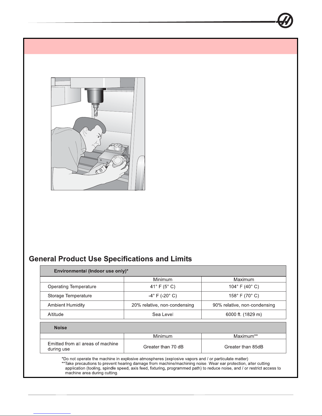
USES AND GUIDELINES FOR PROPER MACHINE OPERATION
All milling machines contain hazards from rotating cutting tools, belts and pulleys, high voltage electricity,
noise, and compressed air. When using milling machines and their component s, basic safety precautions
should always be followed to reduce the risk of personal injury and mechanical damage. READ ALL APPRO-
PRIATE W ARNINGS, CAUTIONS, AND INSTRUCTIONS BEFORE OPERA TING THIS MACHINE.
MODIFICATIONS TO THE M ACHINE
DO NOT modify or alter this equipment in any way . If modifications are necessary, all such requests must be
handled by Haas Automation, Inc. Any modification or alteration of any Haas machining center could lead to
personal injury and/or mechanical damage and will void your warranty .
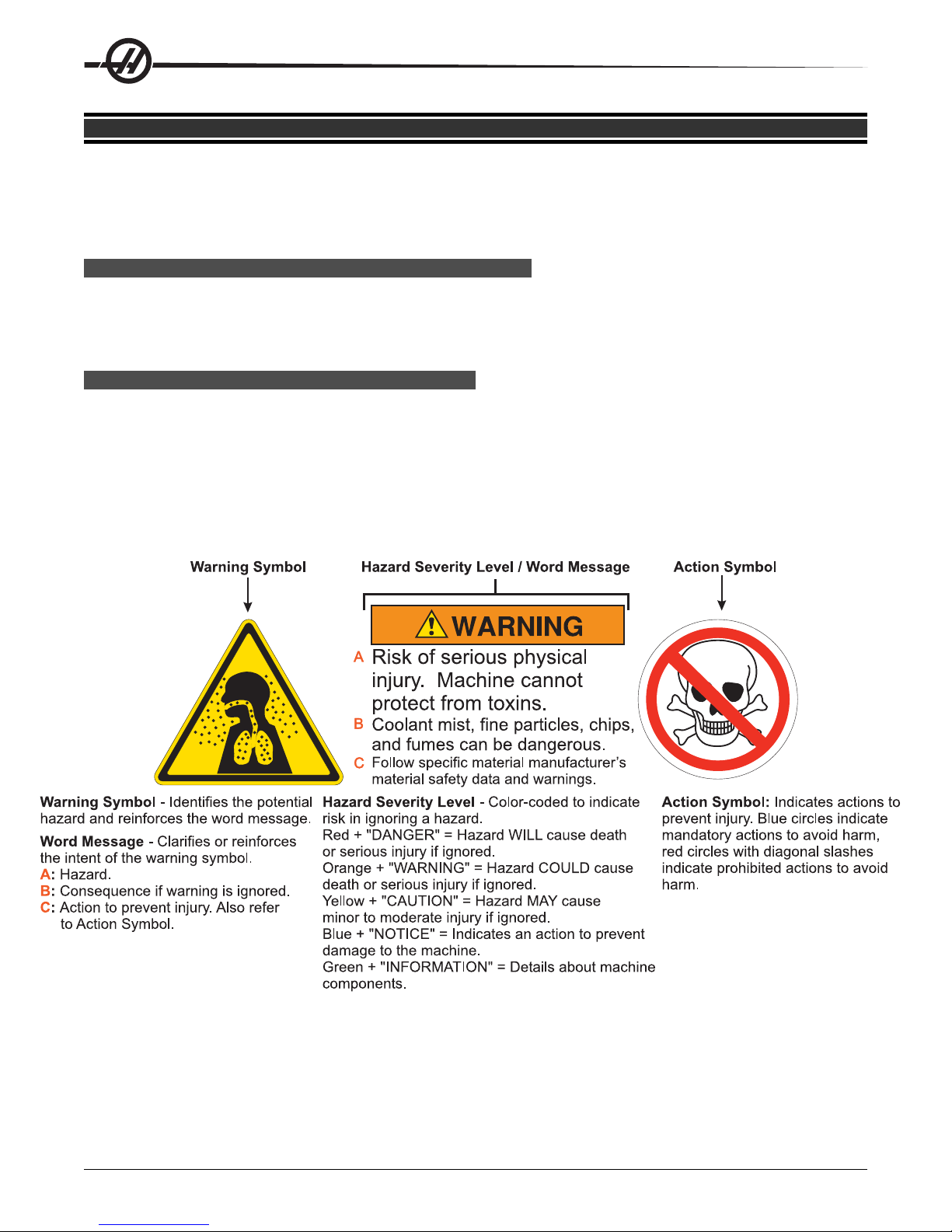
SAFETY P LACARDS
T o help ensure that CNC tool dangers are quickly communicated and understood, hazard symbol decals are placed on
Haas Machines in locations where hazards exist. If decals become damaged or worn, or if additional decals are needed
to emphasize a particular safety point, contact your dealer or the Haas factory. Never allow anyone to alter or
remove any safety decal or symbol.
Each hazard is defined and explained on the general safety decal, located at the front of the machine. Particular locations of hazards are marked with warning symbols. Review and understand the four parts of each safety warning, explained below, and familiarize yourself with the symbols on the following p ages.
4
Safety
96-8000 rev R June 2007
Page 12

96-8000 rev R June 2007
Safety
5
Page 13

MILL W ARNING D ECALS
DECLARATION OF W ARNINGS, CAUTIONS, AND N OTES
Throughout this manual, important and critical information is prefaced with the word “Warning”, “Caution” and “Note”
Warnings are used when there is an extreme danger to the operator and/or to the machine. Take all steps neces-
sary to heed the warning given. Do not continue if you cannot follow the warning instructions. An example warning is:
NEVER PUT HANDS BETWEEN TOOL CHANGER AND SPINDLE HEAD.
Cautions are used when there is the potential for minor personal injury or mechanical damage, for example:
CAUTION! Power down the machine before performing any maintenance tasks.
Notes give additional information to the operator about a particular step or procedure. This information should be
taken into consideration by the operator as the step is performed to ensure there is no confusion, for example:
NOTE: If machine is equipped with the optional extended Z-clearance table, follow
these guidelines:
• Avoid extreme loads on the center of table or far end of table. The weight
of the part should be distributed evenly over the table or one pad.
• Flatness of part should be within 0.002".
6
WARNING!
Safety
96-8000 rev R June 2007
Page 14

LATHE W ARNING D ECALS
96-8000 rev R June 2007
Safety
7
Page 15

8
Safety
96-8000 rev R June 2007
Page 16
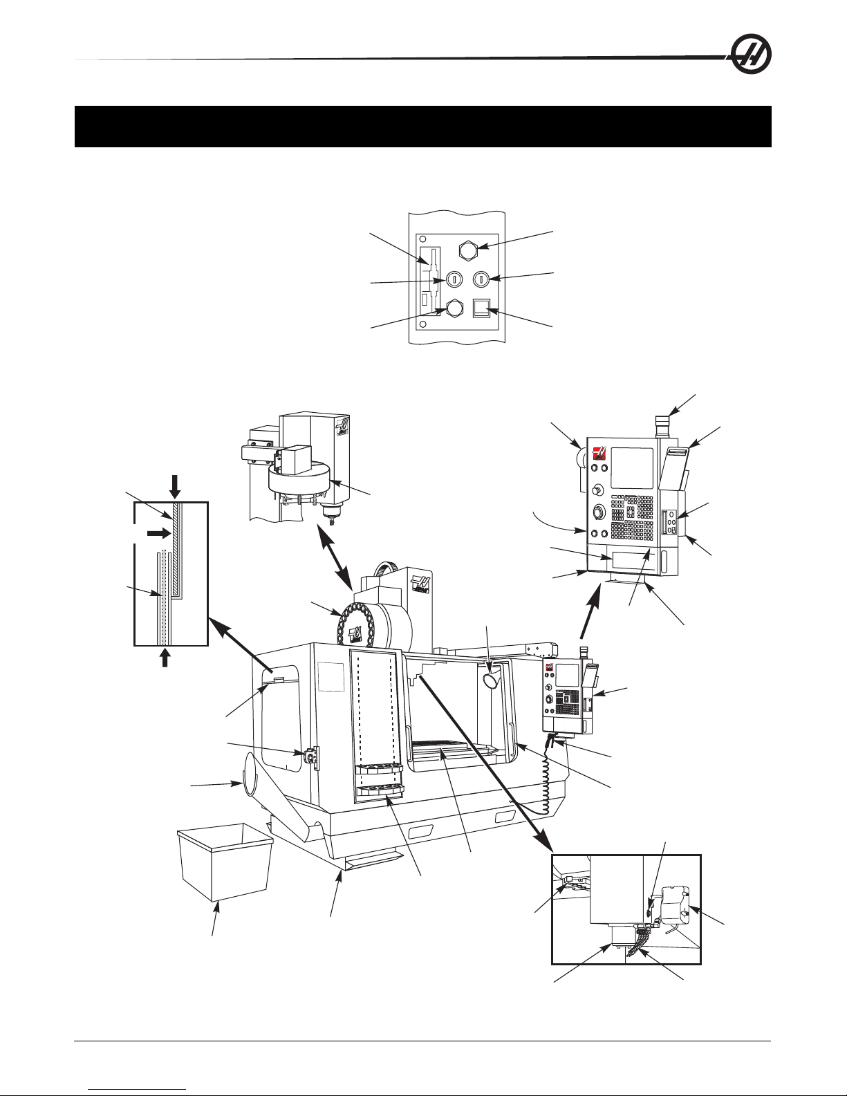
OPERATION
The following is a visual introduction to a HAAS mill. Some of the features shown will be highlighted in their
appropriate sections.
Window
Open
Position
Push in
Window
Closed
Position
Pull down
to Lock in
Place
2
Floppy Disk Drive
Key Memory Lock
Hold to Run Button
MEMORY
LOCK
HOLD TO
RUN
USB
RUN
MODE MODE
WORK LIGHT
GFI
PROTECTED
I
O
SETUP
USB Memory Device
Run/Setup Mode Key
Switch
Work Light Switch
(GFI Protected)
Detail A
(Some Features are Optional)
Remote Jog Control
3
Tool Changer
(Umbrella Type)
Optional
Second
Home
Switch
G & M Code
Reference List
Side Mount
Tool Changer
(SMTC)
1
2
11
1
3
0
14
1
15
9
16
8
17
7
18
6
1
9
5
Work Light (2)
Tool Tray
Beeper
Work Beacon
Clip Board
(See
Detail A)
Operator
Manual &
Assembly
Data
Vise Handle
Holder
1
Pull up
Window
Tool Holding Vise
Chip Chute
Chip Basket
96-8000 rev R June 2007
2-SPEED
2
0
H
P
GEAR
D
RIVE
10,000
RPM
Coolant Tank
Assembly
Tool Crib
Introduction
Table
SMTC
Double Arm
Spindle
Control Pendant
Air Gun
Operator Door (2)
Tool Release Button
Optional
P-Cool
Assembly
Coolant Nozzles
View Rotated 90 CW8
9
Page 17
10
Introduction
96-8000 rev R June 2007
Page 18
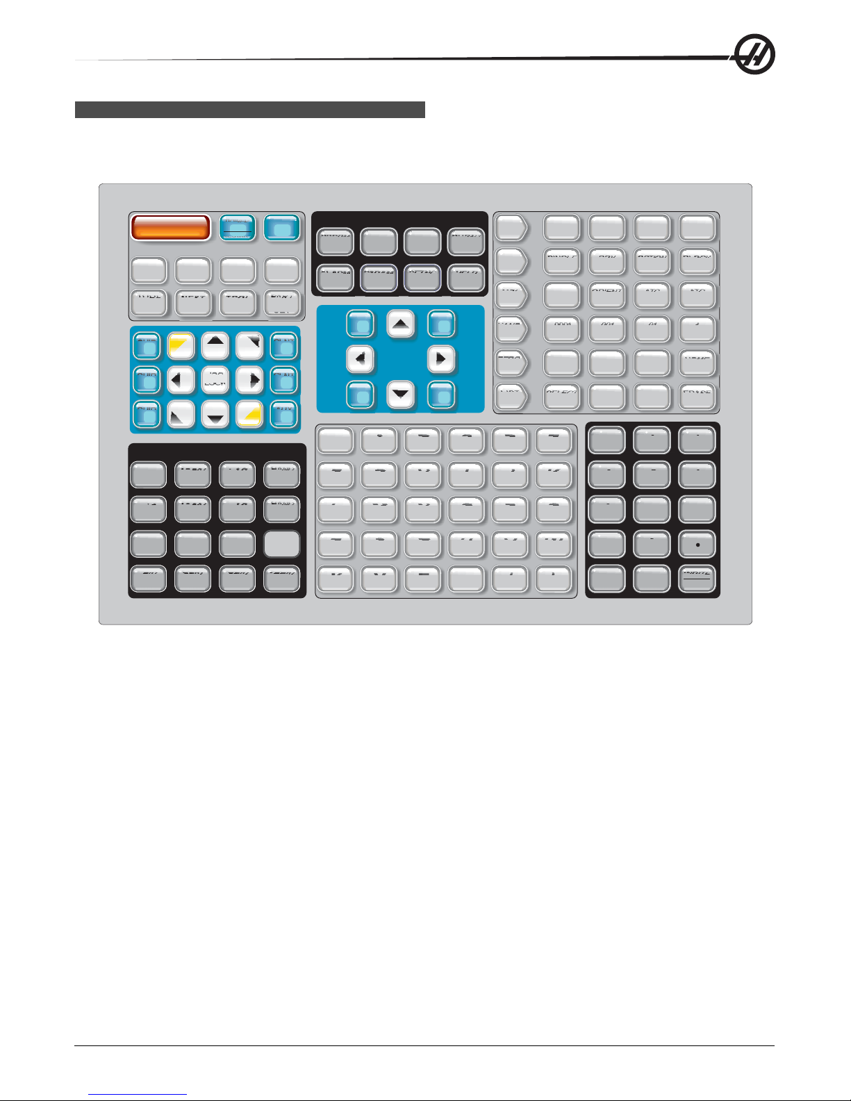
PENDANT K EYBOARD I NTRODUCTION
The keyboard is broken up into eight sections: Function Keys, Jog Keys, Override Keys, Display Keys, Cursor
Keys, Alpha Keys, Mode Keys and Number Keys. In addition there are miscellaneous keys and features
located on the pendant and keyboard which are described briefly .
POWER
RESET
UP
RESTART
RECOVER
F1 F2 F3 F4
TOOL
OFFSET
MEASURE
CHIP
FWD
CHIP
STOP
CHIP
REV
NEXT
TOOL
+B
+A
+X -X
+Y
RELEASE
+Z -Y
JOG
LOCK
-Z
TOOL
OVERRIDES
-10
-10
CW
100%
FEED RATE
100%
SPINDLE SPINDLE
STOP
25% 50% 100%
FEED RATE
SPINDLE
RAPID5%RAPID RAPID RAPID
+10
FEED RATE
+10
CCW
PART
ZERO
SET
CLNT
CLNT
DOWN
-A
-B
CLNT
HAND
CNTRL
FEED
HAND
CNTRL
SPIN
SPINDLE
UP
AUX
PRGRM
CONVRS
ALARM
MESGS
SHIFT
SHIFT
SHIFT
F
L
R
X
HOM E
END
PARAM
DGNOS
DISPLAY
POSIT
CURSOR
G
M
S
Y
OFFSET
SETNG
GRAPH
H
N
T
Z
PAG E
UP
PAG E
DOWN
CURNT
COMDS
HELP
CALC
I
O
U
/
/
EOB
EDIT
MEM
MDI
DNC
HAND
JOG
ZERO
RET
LIST
PROG
J
P
V
[
[
(
INSERT ALTER
SINGLE DRY
BLOCK RUN
COOLNT
SELECT
PROG
EDCBA
K
Q
W
]
]
)
ORIENT
SPINDLE
.0001 .001
.1 1.
ALL
ORIGIN
SEND
&
&
%
%
*
*
+
+
CANCEL
DELETE
OPTION
STOP
SINGL
RECV
@
@
7
$
$
4
,
,
1
=
=
-
SPACE
ATC
FWD
.01
10.
8
5
2
0
UNDO
BLOCK
DELETE
ATC
REV
.1
100.
HOME
G28
ERASE
PROG
:
:
9
!
!
6
?
?
3
#
#
WRITE
ENTER
Power On- Turns the machine on.
Power Off- Turns the machine off.
Spindle Load Meter - Displays the spindle load, in percent.
Emergency Stop - This stops all axes motion, stops the spindle and tool changer, and turns off the coolant
pump.
Jog Handle - This is used to jog all axes. Can also be used to scroll through program code or menu items
while editing.
Cycle Start - S t arts a program. This button is also used to start a program in Graphics mode.
Feed Hold - Will stop all axis motion. Note: Spindle will continue to turn during cutting.
Reset - Will stop the machine (axes, spindle, coolant pump, and tool changer are stopped). This is not a
recommended method to stop the machine, as it may be difficult to continue from that point.
Power Up / Restart - When this key is pressed, the axes will return to the machine zero position and a tool
change may occur. See Setting 81 in the Settings chapter for more information.
Recover - This button aids the operator in recovering the tool changer from an abnormal stop. See the tool
changer section for more information.
96-8000 rev R June 2007
Introduction
11
Page 19

Memory Lock Key Switch - This switch prevent the operator from editing programs and from altering settings
when turned to the locked position. The following describes the hierarchy of locks:
Key switch locks Settings and all programs.
Setting 7 locks parameters.
Setting 8 locks all programs.
Setting 23 locks 9xxx programs.
Setting 119 locks offsets.
Setting 120 locks macro variables.
Second Home Button - This button will rapid all axes to the coordinates specified in work Offset G129. The
sequence is as follows: First, the Z axis is returned to machine zero, then the X and Y axes are moved, then
the Z axis is moved to its second home position. This feature will work in any mode except DNC.
Work Light Switch - This switch will turn on the work light inside of the machine.
Keyboard Beeper - Located at the top of the parts tray . The volume can be adjusted by turning the cover .
FUNCTION K EYS
F1- F4 Keys - These buttons have different functions depending upon which mode of operation you are in. For
example, F1-F4 will cause a different action in Editing mode, than Program mode, than Offset mode. See the
specific mode section for further descriptions and examples.
T ool Offset Meas (T ool Of fset Measure) - Used to record tool length offsets during part setup.
Next T ool - Used to select the next tool from the tool changer (usually used during part setup).
T ool Release - Releases the tool from the spindle when in MDI mode, zero return mode, or handle jog mode.
Part Zero Set - Used to automatically set work coordinate offsets during part setup (see Setting Offsets in the
Operation section).
JOG K EYS
Chip FWD (Chip Auger Forward) - S tarts optional chip auger in the “Forward” direction, moving chip s out of the
machine.
Chip Stop (Chip Auger S top) - S tops auger movement.
Chip REV (Chip Auger Reverse) - S tarts the optional chip auger in the “Reverse” direction, which is useful in
clearing jams and debris from auger.
X/-X, Y/-Y, Z/-Z, A/-A and B/-B (axis keys)- Allows the operator to manually jog axis by holding down the
individual button or pressing the desired axes and using the jog handle.
Jog Lock - Works with the axes buttons. Press jog lock and then an axis button and the axis will move to
maximum travel or until jog lock is pressed again.
CLNT Up (Coolant Up) - Moves the optional Programmable Coolant (P-Cool) nozzle up.
CLNT Down (Coolant Down) - Moves the optional P-Cool nozzle down.
AUX CLNT (Auxiliary Coolant) - Pressing this key while in MDI mode will turn on the optional Through the
Spindle Coolant (TSC) system; pressing it a second time will turn of f TSC.
12
Introduction
96-8000 rev R June 2007
Page 20

OVERRIDE K EYS
These keys give the user the ability to override the speed of non-cutting (rapid) axes motion, programmed feeds
and spindle speeds.
-10 - Decreases current feedrate by 10%.
100% - Sets overridden feedrate to programmed feedrate.
+10 - Increases current feedrate by 10%.
-10 - Decreases current spindle speed by 10%.
100% - Sets overridden spindle speed to programmed speed.
+10 - Increases current spindle speed by 10%.
Hand Cntrl Feed (Handle Control Feedrate) - Pressing this button allows the jog handle to be used to control
the feedrate in ±1% increments.
Hand Cntrl Spin (Handle Control Spindle) - Pressing this button allows the jog handle to be used to control
spindle speed in ±1% increments.
CW - S tarts the spindle in the clockwise direction. This button is disabled on CE (export) machines.
CCW - Start s the spindle in the counterclockwise direction. This button is disabled on CE (export) machines.
The spindle can be started or stopped with the CW or CCW buttons any time the machine is at a Single Block
stop or the Feed Hold button has been pressed. When the program is restarted with Cycle St art, the spindle
will be turned back on to the previously defined speed.
STOP - S top s the spindle.
5% / 25% / 50% / 100% Rapid - Limits machine rapids to the value on the key. The 100% Rapid button allows
maximum rapid.
Override Usage
The feedrate can be varied from 0% to 999% of the programmed value while in operation. This is done with the
feedrate +10%, -10% and 100% buttons. The feedrate override is ineffective during G74 and G84 tapping
cycles. Feedrate override does not change the speed of any auxiliary axes. During manual jogging, the feedrate
override will adjust the rates selected from the keypad. This allows for fine control of the jog speed.
The spindle speed can also be varied, from 0% to 999%, using the spindle overrides. It is also ineffective for
G74 and G84. In the Single Block mode, the spindle may be stopped. It will automatically start up upon
continuing the program (pressing Cycle St art).
By pressing the Handle Control Feedrate key , the jog handle can be used to control feedrate from 0% to 999%
in ±1% increments. By pressing the Handle Control S pindle key , the jog handle can be used to control spindle
speed in ±1% increments (from 0% to 999%).
Rapid moves (G00) may be limited to 5%, 25%, or 50% of maximum using the keypad. If the 100% rapid is too
fast, it may be set to 50% of maximum by Setting 10.
In the Settings page, it is possible to disable the override keys so that the operator cannot select them. These
are Settings 19, 20 and 21.
96-8000 rev R June 2007
Introduction
13
Page 21

The Feed Hold button acts as an override button as it sets the rapid and feed rates to zero when it is pressed.
The Cycle Start button must be pressed to proceed af ter a Feed Hold. The door switch on the enclosure also
has a similar result but will display “Door Hold” when the door is opened. When the door is closed, the control
will be in Feed Hold and Cycle Start must be pressed to continue. Door Hold and Feed Hold do not stop any
auxiliary axes.
The operator can override the coolant setting by pressing the COOLNT button. The pump will remain either on
or off until the next M-code or operator action (see Setting 32).
Overrides can be reset to defaults with an M30 and/or pressing Reset (See Setting 83).
DISPLAY K EYS
Displays keys provide access to the machine displays, operational information and help pages. Some of these
keys will display additional screens when pressed more than once.
Prgrm/Convrs - Displays the currently selected program. In Edit mode, pressing the button twice will enter the
Quick Code (See Quick Code section) feature and pressing it three times will enter the Visual Quick Code
feature (See Visual Quick Code section in Quick Code).
Posit (Position) - Displays the position of the machine axes. Pressing the Page Up/Down buttons scroll
through operator, machine, work, and distance-to-go format s and displays them in larger formats.
Offset - Displays the tool length geometry , radius offsets, wear of fsets, and coolant position. Pressing Offset
button twice or pressing the Page Up button will access the work offsets page.
Curnt Comds (Current Commands) - Displays the current program details (for example G , M, H and T codes),
Spindle load information and machine axes positions while the program runs. Press Page Up/ Down to view
tool load/vibration (See the tool load/vibration section), tool life (See the tool life section), maintenance, macro
variables, program timers and program code details.
Alarm / Mesgs (Alarms / Messages) - Displays the alarm viewer and message screens. There are three alarm
screens, the first shows the currently active alarms (first press of the Alarm/Mesgs button). Pressing the Right
Arrow button switches to the Alarm History screen, which keep s a history of recent alarms.
Pressing Right Arrow again switches to the alarm viewer screen. This screen shows one alarm at a time with
its description. The default will be the last alarm in the alarm history. The user can then scroll through the
alarms by pressing the Up and Down Arrow buttons. Also, the user can enter an alarm number and press
Enter/Write and the name and description will be displayed.
Pressing Alarm/mesgs a second time will display a page for user messages and notes. Use the keyp ad to
enter messages for other operators/programmer or write notes for a current project. If there is a message, every
time the machine is powered on the messages page will display . Messages are displayed at power up until
they are erased. See Message section for more details.
Param / Dgnos (Parameters / Diagnostics) - Displays parameters that define the machine's operation. To find
a known parameter, type in the number and press the up or down arrow . Parameters are set at the factory and
should not be modified by the user.
A second press of the Param / Dgnos key will display the first page of diagnostic data. This information is
mainly used for troubleshooting by a certified Haas service technician. The first page of diagnostic data is
discrete inputs and outputs. Pressing Page Down will display the additional pages of diagnostic data.
Setng / Graph (Settings / Graphics) - Displays and allows changing of user settings. (Note that the settings
are grouped; these groups are for a specific subject). To find a known setting, type in the number and press the
up or down arrow.
14
Introduction
96-8000 rev R June 2007
Page 22

Pressing the Setng / Graph key a second time enables Graphics mode. In Graphics mode the user can view
the generated tool path of the program and, if necessary , debug the program before running it (See Graphics
Mode in the Operation section)
Help / Calc (Help / Calculator) - Displays an abbreviated manual. In this on-screen manual there are brief
descriptions of G and M codes, definitions of control features, troubleshooting and maintenance issues.
Pressing Help/ Calc a second time will display the help calculator. Press the Page Down button to scroll
through the calculator pages (see the calculator section).
CURSOR K EYS
Cursor Keys give the user the ability to move to various screens and fields in the control and are used in the
editing of CNC programs.
Home - This button will move the cursor to the top-most item on the screen; in editing, this is the top left block
of the program.
Up / Down Arrows - moves up/down one item, block or field.
Page Up / Down - Used to change displays or move up/down one page when viewing a program.
Left Arrow - Used to select individually editable items when viewing a program; moves cursor to the left. It is
used to scroll through setting selections.
Right Arrow - Used to select individually editable items when viewing a program; moves cursor to the right. It
is used to scroll through setting selections and moves the zoom window right when in graphics mode.
End - This button generally moves the cursor to the bottom-most item on the screen. In editing, this is the last
block of the program.
ALPHA K EYS
The alpha keys allow the user to enter the letters of the alphabet along with some special characters. Some of
the special characters are entered in by first pressing the “Shift” key .
Shift - The shift key provides access to additional characters on the keyboard. The additional characters are
seen in the upper left of some of the alpha and number keys. Pressing Shift and then the character will enter
that character on the data entry line. When entering text, UPPER CASE is the default, to enter lower case
characters, press and hold the Shift key .
When a control has a fifth axis installed, the B axis is selected for jogging by pressing the Shift button and
then the +/-A jog keys.
EOB - This is the End-Of-Block character . It is displayed as a semicolon (;) on the screen and it signifies the
end of a program line.
( ) - Parentheses are used to separate CNC program commands from user comments. They must always be
entered as a pair . Note: Any time an invalid line of code is received through the RS-232 port while receiving a
program, it is added to the program between parenthesis.
/ - The right slash is used in the Block Delete feature and in Macro expressions. If this symbol is the first
symbol in a block and a Block Delete is enabled, then that block is ignored at run time. The symbol is also
used for division (divide by) in macro expressions (see the Macro section).
[ ] - Square brackets are used in macro functions. Macros are an optional software feature (see the Macro
section).
96-8000 rev R June 2007
Introduction
15
Page 23

MODE K EYS
Mode keys change the operational state of the CNC machine tool. Once a mode button is pressed, the buttons
in the same row are made available to the user. The current mode is always displayed on the top line just to
the right of the current display in between parenthesis.
Edit- Selects edit mode. This mode is used to edit programs in control's memory.
Insert - Pressing this button will enter commands into the program in front of the cursor. This button will also
insert the text from the clipboard to the current cursor location, and is also used to copy blocks of code in a
program (See Advanced Editor Section)
Alter - Pressing this button will change the highlighted command or text to the newly entered commands or
text. This button will also change the highlighted variables to the text stored in the clipboard, or move a selected block to another location.
Delete - Deletes the item that the cursor is on, or deletes a selected program block.
Undo - Undoes up to the last 9 edit changes, and deselects a highlighted block.
MEM (Memory) - Selects the memory mode. This page displays the current program that is selected in the list
of programs.
Single Block - Turns single block on or off. When single block is on, only one block of the program is ex-
ecuted, for every press of Cycle Start.
Dry Run - This is used to check actual machine movement without cutting a part. (See the Dry Run section in
the Operation Chapter)
Opt Stop (Optional Stop) - T urns on and off optional stops. Also see G103 in the G-Code chapter .
When this feature is ON and an M01 (optional stop) code is programmed, the machine will stop when it
reaches the M01. The machine will continue once Cycle S tart is pressed. However , depending on the lookahead function (G103), it may not stop immediately (See block look ahead section). In other words, the block
look-ahead feature may cause the Optional Stop command to ignore the nearest M01.
If the Optional Stop button is pressed during a program it will take ef fect on the line after the highlighted line
when the Opt Stop button is pressed.
Block Delete - Turns On/Off block delete function. Blocks with a slash (“/”) as the first item are ignored (not
executed) when this option is enabled. If a slash is within a line of code, the commands after the slash will be
ignored if this feature is enabled. Block Delete will take effect two lines after Block Delete is pressed, except
when cutter compensation is used, in this case, block delete will not take effect until at least four lines after
the highlighted line. Processing will slow down for paths containing block deletes during high-speed machining.
Block Delete will stay active when power is cycled.
MDI/DNC - MDI mode is the “Manual Data Entry” mode where a program can be written but it is not entered
into memory. DNC mode “Direct Numeric Control”, allows large programs to be “drip fed” into the control so it
can be executed (See DNC mode section)
Coolnt (Coolant) - Turns the optional coolant on and off.
Orient Spindle - Rotates the spindle to a given position and then locks the spindle. Can be used during setup
to indicate parts.
A TC FWD - Rotates the tool turret to the next tool. To load a specific tool into the spindle, enter MDI mode,
type a tool number (T8) and press A TC FWD.
A TC REV - Rotates the tool turret to the previous tool. To load a specific tool into the spindle, enter MDI mode,
type a tool number (T10) and press ATC REV.
Handle Jog - Selects axis jogging mode .0001, .1 - 0.0001 inches (metric 0.001mm) for each division on the
jog handle. For dry run, .1 inches/min.
16
Introduction
96-8000 rev R June 2007
Page 24

.0001/.1, .001/1., .01/10., .1/100. - The first number (top number), when in inch mode, selects that amount to
be jogged for each click of the jog handle. When the mill is in MM mode the first number is multiplied by ten
when jogging the axis (e.g. .0001 becomes 0.001mm). The second number (bottom number) is used for dry run
mode and is used to select the speed feedrate and axis motions.
Zero Ret (Zero Return) - Selects Zero Return mode, which displays axis location in four different categories,
they are; Operator, W ork G54, Machine and Dist (distance) to go. You can page up or down to view each
category in a larger format by itself.
All - Returns all axes to machine zero. This is similar to Power Up/Restart except a tool change will not occur .
This can be used to establish the initial axes zero position.
Origin - Sets selected displays and timers to zero.
Singl (Single) - Returns one axis to machine zero. Press the desired axis letter and then press the Singl Axis
button. This can be used to establish the initial axis zero position.
HOME G28 - Returns all axes to machine zero in rapid motion. Home G28 will also home a single axis in the
same manner if you enter an axis letter and press the home G28 button. CAUTION! There is no warning
message to alert the operator of any possible collision. For example, if the Z-axis is down in amongst parts on
the table when X or Y is zeroed, a crash can result.
List Prog (List Programs) - Displays the programs stored in the control.
Select Prog - Makes the highlighted program, in the program list, the current program. Note: The current
program will have an “*” preceding it in the program list.
Send - Transmits programs out the RS-232 serial port. (See RS-232 section)
Recv - Receives programs from the RS-232 serial port. (See RS-232 section)
Erase Prog - Erases the highlighted program in Memory mode or the entire program when in MDI mode.
NUMERIC K EYS
The numeric keys give the user the ability to enter numbers and a few special characters into the control.
Cancel - The Cancel key is used to delete the last character entered.
Space - Used to format comments placed into programs or in the message area.
Write / Enter - General purpose enter key .
- (Minus sign)- Used to enter negative numbers.
. (Decimal Point)- Used for decimal precision.
POSITION D ISPLAYS
The following are the position displays.
Home Page
This display shows the four displays (Operator, W ork, Machine and Distance-to-go) simultaneously . Use the
Page Up/Down keys or the UP/Down Arrows to scroll through these p ages.
Operator Display
This display is used to show the distance the operator has jogged any of the axes. This does not represent the
actual distance the axis is from machine zero. Axes can be zeroed by selecting an axis (X, Y or Z) and
pressing the Origin key .
96-8000 rev R June 2007
Introduction
17
Page 25

Work Display
This displays the position of X, Y and Z in relation to the part; not machine zero. On power-up, it will display the
value in work offset G54 automatically . The position can only be changed by entering values in work of fsets
G54 through G59, G1 10 through G129, or by commanding a G92 in a program.
Machine Display
This display is the actual axes position away from machine zero.
Distance T o Go
This display shows the distance remaining before the axes reaches its commanded position.
OFFSETS D ISPLAY
There are two offsets pages. The first offset page is the Tool Geometry/Wear page. The second is the Work
Zero offset page.
Tool Geometry/Wear
The Tool/Geometry page is displayed by pressing the Offset button. This page displays tool numbers, tool
length geometry and wear values, tool radius geometry and wear values, flutes values and actual diameter
values. If the mill has the optional programmable coolant unit, this page will also display the coolant position
entered for each tool. To enter values into these fields key in a number and press F1. Keying in a number and
pressing F2 will set the negative of the entered value into the offsets. Entering a value and pressing Write/Enter
will add the value to what is currently entered. To clear all the values on the page press Origin, the mill will
prompt the operator with "Zero All (Y/N) press Y to zero all or press N to leave all the values unchanged.
Work Zero Offset
The Work Zero Offset page is displayed by pressing the Offset button twice. This page displays the values
entered so that each tool knows where the part is located on the table. A value can be set for each axis (X,Y
and Z). The operator can scroll to each column by using the arrow key or by pressing the Page Up or Down
buttons to access the other offsets in the Work Zero section. In order for each tool to locate the part, the tools
used in a program must be "T ouched of f" the part. A value can be entered by typing in a number and pressing
F1, or the value added to an existing value by pressing Enter/Write. Keying in a number and pressing F2 will
set the negative of the entered value into the offsets. To clear all the values on the page press Origin, the mill
will prompt the operator with "Zero All (Y/N) press Y to zero all or press N to leave all the values unchanged.
CURRENT C OMMANDS D ISPLAY
The following are several Current Command pages in the control. Press the Current Commands button and use
the Page Up/Down buttons to navigate through the pages.
Program Command Check Display This display shows a current overview of the important commands. It
shows the programmed spindle speed (PGM), the commanded spindle speed commanded by the program
(CMD), and the actual spindle speed (ACT). In addition, this display shows the CW, CCW , or stopped command being sent to the spindle and the current transmission gear (if equipped) position.
This display also shows the position of the axes. There are four coordinates displayed (operator , work, machine, or distance to go) and are selected using the cursor Up/Down or Page Up/Down keys.
If the machine has the optional Programmable Coolant (P-Cool), the current spigot position will be displayed as
well.
Current Display Command This display shows the current program codes and their current value. These
values may not be changed in this display.
Macro Variables Display This display shows a list of the macro variables and their present values. As the
control runs the program, the variables will be updated. In addition the variables may be modified in this display;
refer to the “Macros” section for more information.
18
Introduction
96-8000 rev R June 2007
Page 26

Operation Timers Display This display shows the current power-on time, cycle start time (the amount of total
time the machine has been running a program), and the feed time (total amount of time the machine has been
feeding). These times may be reset to zero by using the cursor up and down keys to highlight the desired title
and pressing the ORIGIN button.
Listed below these times are two M30 counters, these counters are used for counting completed parts. They
may be set to zero independently to provide for the number of parts per shift and total parts.
T ool Life display This display shows the time the tool is used in a feed (Feed-Time), the time the tool is in the
spindle (T ot al-Time), and the number of times the tool has been selected (Usage). This information is used to
assist in predicting tool life. The values in this display can be reset to zero by highlighting the value and
pressing the Origin button. Note: The maximum value is 32767, once this value is reached, the control will start
back at zero.
This display may also be used to generate an alarm when a tool has been used a specific number of times.
The last column is labeled “Alarm,” entering a number in that column will cause the machine to generate an
alarm (#362 T ool Usage Alarm) when that count is reached.
T ool Load Monitor and Display The operator can enter the maximum amount of tool load, in %, that is
expected for each tool. The operator can select the appropriate action to be taken when this load is exceeded.
This display provides for the entry of this alarm point and also displays the largest load that tool has seen in a
previous feed.
NOTE: Surface Feet per Minute (SFM) and Chip Load are displayed on the Current Commands page. SFM is
displayed as fpm (feet per minute) or mpm (meters per minute).
The tool load monitor function operates whenever the machine is in a feed operation (G01, G02, or G03). If the
limit is exceeded the action specified in Setting 84 will occur (See settings section for a description).
Axis Load Monitor Axis load is 100% to represent the maximum continuous load. Up to 250% can be shown,
however an axis load above 100%, for an extended period of time, can lead to an overload alarm.
Maintenance This page allows the operator to activate and deactivate a series of checks (see Maintenance
section).
ALARMS / MESSAGES D ISPLAY
Alarms
The Alarms display is selected by pressing the ALARM / MESGS button. There are three types of Alarms
screens. The first shows any current alarms. Pressing the Right Arrow key switches to the Alarm History
screen, which shows the previously received alarms. Pressing Right Arrow again switches to the alarm viewer
screen. This screen shows one alarm at a time with its description. The user can then scroll through all the
alarms by pressing the Up and Down Arrow keys. Also, the user can enter an alarm number and press W rite/
Enter and the name and description will be displayed. Pressing Page Down will display a page for user messages and notes.
Note: The Cursor and Page Up and Page Down buttons can be used to move through a large number of alarms.
Messages
The Message Display can be selected by pressing the Alarm/Mesgs button twice. This is an operator message
display and has no other effect on operation of the control. Use the keypad to enter the messages. The cancel
and space buttons can be used to remove existing messages and the Delete button can be used to remove an
entire line. Data is automatically stored and maintained even in a power-off state. The message display page
will come up during power-up if there are no alarms present.
96-8000 rev R June 2007
Introduction
19
Page 27

SETTING / GRAPHIC D ISPLAY F UNCTION
The Settings are selected by pressing the Setng/Graph button. There are some special functions in the
settings which change the way the mill behaves; refer to the “Settings” section for a more detailed description.
The Graphics function is selected by pressing the Setng/Graph button twice. Graphics is a visual dry run of
your part program without the need to move the axes and risk tool or part damage from programming errors.
This function may be considered more useful than the Dry Run mode, because all of your work offsets, tool
offsets, and travel limits can be checked before running the machine. The risk of a crash during setup is greatly
reduced.
Graphics Mode Operation
T o run a program in Graphics, a program must be loaded and the control must be in either MEM or MDI mode.
Press the Setng/Graph key twice to select the Graphics Mode.
The Graphics display has a number of features within it.
Key Help Area The right side of the top line is the function key help area. Function keys that are currently
available are displayed here with a brief description of their usage.
Locator Window The lower right part of the screen has two modes. It can display the whole table area and
indicate where the tool is currently located during simulation. Or it can be used to display four lines of the
program that is being executed. The F4 key is used to toggle between these two modes.
T ool Path Window In the center of the display is a large window that represent s a top view of the X and Y
axes. It displays tool paths during a graphics simulation of the program. Rapid moves are displayed as dotted
lines, while feed motion is displayed as fine continuous lines. (Note: Setting 4 can disable the rapid path.) The
places where a drilling canned cycle is used are marked with an X. Note: Setting 5 can disable the drill mark.
Scaling the Tool Path W indow The tool p ath window can be scaled. After running a program, pressing F2
will scale the tool path. Use the Page Down key and the arrow keys to select the portion of the tool path to be
magnified. Pressing F2 will display a rectangle (zoom window) indicating the magnified area. Note: The Help
area will flash, indicating the view rescaling process. The locator window (small view at the bottom right) shows
the entire table with an outline of where the Tool Path window is zoomed. The Page Up key reduces the zoom
(unzooms) the rectangle one step. After sizing and/or moving the zoom window , pressing the Write/Enter key
will complete the zoom process and re-scale the Tool Path window . After the Tool Path window is re-scaled, the
T ool Path window is cleared and the program must be re-run to see the tool p ath.
The scale and position of the Tool Path window is saved in Settings 65 through 68. Leaving graphics to edit the
program and then returning to Graphics will keep the previous scaling in effect.
Pressing F2 and then the Home key will expand the Tool Path window to cover the entire table.
Z Axis Part Zero Line This feature consists of a horizontal line displayed on the Z-axis bar at the top-right
corner of the graphics screen to indicate the position of the current Z-axis work offset plus the length of the
current tool. While a program is running, the shaded portion of the bar indicates the depth of Z-axis motion. The
user is able to watch the position of the tool tip relative to the Z-axis part zero position as the program runs.
Control Status The lower left portion of the screen displays control status. It is the same as the last four lines
of all other displays.
Position Window The location of all enabled axes can be viewed in this window. Press F3 to open this
window. Additional presses of the F3 key or the up and down arrows will display the various position format s.
This window also displays the current scale of the tool path window and the current simulated tool number .
20
Introduction
96-8000 rev R June 2007
Page 28

DATE AND T IME
The control contains a clock and date function. To view the time and date, press the Help button until the date
and time appears.
Setting the date and time, use the Up and Down arrow keys to select the date or time. Use the Right and Left
arrow keys or the jog handle to make adjustments.
SCREEN S AVER
The Haas machine includes a screen saver for the operator’s pendant. Af ter a period of time, with no keyboard
activity the screen saver will start. When the screen saver is active, the words “Screen saver” will be displayed
and will change positions every 2 seconds. The screen saver is cancelled by any key press, jog handle motion
or machine alarm. The screen saver will not activate if the control is in Sleep, Jog, Edit, Graphics, MEM or MDI
mode with the PRGRM screen displayed.
HELP / CALCULATOR F UNCTION
Help
The Help Feature is selected by pressing the Help button, which will display a mini-manual.
Use the alphanumeric buttons to select the topics, or use the Page Up/Down button or Up/Down arrows to
navigate through the help topics and descriptions.
Calculator
The Calculator function is selected by pressing the Help key twice. Use the Page Up / Down keys to move
through the pages.
All of the Calculator functions will do simple add, subtract, multiply , and divide operations. When one of the
functions is selected, a calculator window appears with the possible operations (LOAD, +, -, *, and /). LOAD is
initially highlighted, and the other options can be selected with the left and right cursor arrows. Numbers are
entered by typing them in and pressing the Write/Enter key . When a number is entered and LOAD is selected,
that number will be entered into the calculator window directly . When a number is entered when one of the
other functions (+ - * /) is selected, that calculation will be performed with the number just entered and any
number that was already in the calculator window. The calculator will also accept a mathematical expression
such as 23*4-5.2+6/2. It will evaluate it (doing multiplication and division first) and place the result, 89.8 in this
case, in the window.
Function Keys: The function keys can be used to copy and paste the calculated results into a section of a
program or into another area of the Calculator feature.
F3 In EDIT and MDI modes the F3 key will copy the highlighted triangle/circular milling/tapping value into the
data entry line at the bottom of the screen. This is useful when the calculated solution will be used in a program.
In the Calculator function, pressing F3 copies the value in the calculator window to the highlighted data entry for
Trig, Circular or Milling/Tapping calculations.
F4 In the Calculator function, this button uses the highlighted Trig, Circular or Milling/Tapping data value to
load, add, subtract, multiply , or divide with the calculator .
Trigonometry Help Function
The Trigonometry calculator page will help solve a triangular problem. Enter the lengths and the angles of a
triangle and when enough data has been entered, the control will solve for the triangle and display the rest of
the values. Use the Cursor Up/Down buttons to select the value to be entered with WRITE. For inputs that have
more than one solution, entering the last data value a second time will cause the next possible solution to be
displayed.
96-8000 rev R June 2007
Introduction
21
Page 29
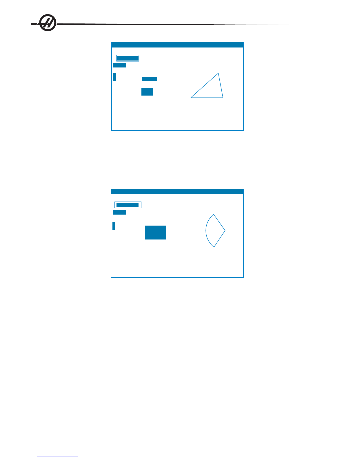
F3 copies calculator value to highlighted field in this
or
other calculator screens. F3 also copies calculator
value
to the data entry line of edit screens.
F4
copies highlighted data to the calculator field.
SIDE 1 10.0000
SIDE 1
SIDE 2
SIDE 3
ANGLE 3
ANGLE 2
ANGLE 1
SIDE 2 14.7958
SIDE 3 14.4244
(MACHINE ANGLE 1 40.000
0.0000
in ANGLE 2 72.000
0.0000
in 68.000
Z
3.5179 in
Y
Y ANGLE
3
LOAD + - * /
HELP (MEM) O00000 N00000000
G91 G2 X3. Y22. 0416 R13. 4536
16 19. J10.
16
R13. 4536
16
19. J10
CENTER X 13.0000
CENTER
Y 20.0000
START
X 4.0000
START
Y 10.0000
END
X 7.0000
32.0416
13.4536
111.527
DIRECTION
CW
END
Y
RADIUS
ANGLE
LOAD + - * /
(MACHINE)
0.0000
in
0.0000
in
Z
3.5179 in
X
Y
CALCULATOR
0.000000000
LOAD +-*/
(MACHINE ANGLE 1 40.000
0.0000 in ANGLE 2 72.000
Y
0.0000 in 68.000
Y ANGLE 3
Z 3.5179 in
SIDE 1 10.0000
SIDE 2 14.7958
SIDE 3 14.4244
F3 copies calculator value to highlighted field in this
or other calculator screens. F3 also copies calculator
value to the data entry line of edit screens.
F4 copies highlighted data to the calculator field.
SIDE 2
ANGLE 1
SIDE 3
ANGLE 3
SIDE 1
ANGLE 2
Circular Interpolation Help
The Circular calculator page will help solve a circle problem. You enter the center, radius, angles, start and end
points; when enough data has been entered, the control will solve for the circular motion and display the rest of
the values. Use the Cursor Up/Down buttons to select the value to be entered with Write. In addition, it will list
alternate formats that such a move could be programmed with a G02 or G03. The formats can be selected
using the Cursor Up/Down buttons, and the F3 button will import the highlighted line into a program you are
editing.
HELP (MEM) O00000 N00000000
CALCULATOR
0.000000000
LOAD +-*/
(MACHINE)
0.0000 in
X
0.0000 in
Y
Z 3.5179 in
G91 G2 X3. Y22. 0416 R13. 4536
CENTER X 13.0000
CENTER Y 20.0000
START X 4.0000
START Y 10.0000
END X 7.0000
END Y
RADIUS
ANGLE
32.0416
13.4536
111.527
DIRECTION CW
16 19. J10.
16 R13. 4536
16 19. J10
E
S
For inputs that have more than one solution, entering the last data value a second time will cause the next
possible solution to be displayed. To change the CW value to the CCW value, highlight the CW/CCW column
and press the Write/Enter button .
Circle-Line Tangent Calculator
This feature provides the ability to determine points of intersection where a circle and a line meet as tangent.
Enter two points, A and B, on a line and a third point, C, away from that line, the control will calculate the point
of intersection. The point is where a normal line from point C will intersect with the line AB, as well as, the
perpendicular distance to that line.
22
Introduction
96-8000 rev R June 2007
Page 30
CIRCLE-CIRCLE TANGENT
CALCULATOR
PGM F0.
ACT
F0.
PGM
S0
CMD
S0
ACT
S0
MILLING
TAPPING
THREADS 3. 0000 /IN
RPM
40
13.
3333 IN/MINFEED
CUTTER DIA 0. 5000 IN
SURFACE
SPEED 5. 0000 FT/MIN RECOMMENDED
38
FLUTES
4
FEED
6. 0000 IN/MIN
0.
0365 IN RECOMMENDED
MATERIAL
LOW CARBON UNALLOYED STEEL
TOOL
TYPE CARBIDE
CUT
WIDTH 2. 0000 IN
CUT
DEPTH 0. 0500 IN REQUIRED POWER
RPM
CHIP
LOAD
LOAD
+ - * /
(MACHINE)
0.0000
in
0.0000
in
3.5179
in
X
Y
Z
CIRCLE1 X
CIRCLE1 Y
RADIUS 1
CIRCLE2 X
CIRCLE2 Y
RADIUS 2
TANGT A X
TANGT B X
TANGT C X
TANGT D X
5.0000
6.0000
4.0000
0.0000
0.0000
2.0000
1.3738
Y
7.6885
7.3147
Y
2.7378
-1.8131
Y
0.8442
1.1573
Y
-1.6311
a
c
b
d
Type: STRAIGHT
Use F and T to form G-code.
F1 for alternate solution
CIRCLE-LINE TANGENT
POINT A X
POINT C X
RADIUS
TANGT PT X
TANGT PT Y
Y
XPOINT B
Y
Y
5.0000
3.0000
1.0000
4.0000
0.0000
0.0000
4.1231
1.0000
4.0000
b
a
c
Circle-Circle Tangent Calculator
This feature provides the ability to determine points of intersection between two circles or points. The user
provides the location of two circles and their radii. The control then calculates all the intersection points that
are formed by lines tangent to both circles. Note: For every input condition where there are two disjointed
circles, there are up to eight intersection points. Four points are obtained from drawing straight tangents and
four points by forming cross tangents. The F1 key is used to toggle between the two diagrams. When "F" is
pressed, the control will prompt for the from and to points (A, B, C, etc.) that specify a segment of the diagram.
If the segment is an arc, the control will also prompt for C or W (CW or CCW). Sample G code is then displayed at the bottom of the screen. When "T" is entered, the previous to point becomes the new from point and
the control prompts for a new to point. To enter the solution (line of code), switch to MDI or Edit and press F3,
as the G-code is already on the input line.
Milling/Tapping Help
The Milling/T apping Help page will help you solve equations relating to milling and t apping. They are:
1. SFM (Surface Feet per Minute) = (CUTTER DIAMETER IN.) * RPM * 3.14159 / 12
2. (FEED IN./MIN.) = RPM / (THREAD PITCH)
3. (CHIP LOAD IN.) = (FEED IN./MIN.) / RPM / #FLUTES
Enter all but one of the values and the control will compute the remaining value. Note that the RPM value for
the first two equations are the same entry .
HELP (MEM) O00000 N00000000
CALCULATOR
0.000000000
LOAD
+-*/
(MACHINE)
0.0000 in
X
0.0000 in
Y
3.5179 inZ
96-8000 rev R June 2007
Note: When metric units are selected, the units displayed change to millimeters, threads per mm, mm per
minute, and meters, respectively .
PGM F0.
ACTF0.
PGM S0
CMD S0
ACT S0
MILLING
CUTTER DIA 0. 5000 IN
SURFACE SPEED 5. 0000 FT/MIN RECOMMENDED
RPM
FLUTES4
FEED 6. 0000 IN/MIN
CHIP LOAD
MATERIAL LOW CARBON UNALLOYED STEEL
TOOL TYPE CARBIDE
CUT WIDTH 2. 0000 IN
CUT DEPTH 0. 0500 IN REQUIRED POWER
TAPPING
THREADS 3. 0000 /IN
RPM40
38
0. 0365 IN RECOMMENDED
13. 3333 IN/MINFEED
Introduction
23
Page 31

Materials
The Milling calculator includes a field called MATERIAL, which, when highlighted, allows the operator to select
a type of material from the list using the left and right arrow keys.
A recommended surface speed and chip load will be displayed based on the material chosen, as shown.
SURFACE SPEED *.*** FT/MIN RECOMMENDED **** T O *****
CHIP LOAD *.*** IN RECOMMENDED *.*** TO *.***
Also, the required horsepower will be calculated and displayed as shown below on the right.
CUT DEPTH *.*** IN REQUIRED POWER *.* HP
When in metric mode, the required power is displayed as KW (kilowatt).
Drill/Tap Chart
Pressing the Help/Calc button a third time displays a Drill and Tap chart
SPINDLE W ARM-UP P ROGRAM
All spindles, which have been idle for more than 4 days, must be thermally cycled prior to operation. This
warm-up will prevent possible overheating of the spindle due to the settling of lubrication. A 20-minute warm-up
program (number O02020) has been supplied with the machine which will bring the spindle up to speed slowly ,
allowing the spindle to thermally stabilize. This program may also be used daily for spindle warm-up prior to
high-speed use.
RUN-STOP-JOG-CONTINUE
This feature allows the operator to stop a running program, jog away from the part, and then resume program
execution. The following is an operation procedure:
1. Press Feed Hold to stop the running program
2. Press X, Y or Z followed by the Handle Jog button. The control will store the current X, Y, and Z positions.
Note: Axes other than X, Y, and Z cannot be jogged.
3. The control will display the message "Jog Away". Use the jog handle, remote jog handle, jog and jog-lock
buttons to move the tool away from part. Control buttons such as AUX CLNT (optional Through S pindle Coolant
- TSC), or Coolnt to turn on/off the coolant (AUX CLNT requires that the spindle is rotating and the door is
closed). The spindle can be controlled by pressing CW , CCW , S top, Tool Release. If necessary, tool inserts
can be changed. Caution: When the program is continued, the old offsets will be used for the return position.
Therefore, it is unsafe and not recommended to change tools and offsets when the program is interrupted.
4. Jog to a position as close as possible to the stored position, or to a position where there will be an unobstructed rapid path back to the stored position.
5. Return to the previous mode by pressing MEM, MDI, or DNC. The control will only continue if the mode that
was in effect when stopped is re-entered.
6. Press Cycle Start. The control will display the message Jog Return and rapid X and Y at 5% to the position
where Feed Hold was pressed, then return the Z-axis. Caution: The control will not follow the path used to jog
away. If Feed Hold is pressed during this motion, the mill axes motion will p ause and display the message "Jog
Return Hold". Pressing Cycle Start will cause the control to resume the Jog Return motion. When the motion is
completed, the control will again go into a feed hold state.
7. Press Cycle Start again and the program will resume normal operation.
Also see Setting 36 Program Restart.
24
Introduction
96-8000 rev R June 2007
Page 32

COOLANT L EVEL G AUGE
The coolant level is displayed on the control on the Current Commands page. A vertical bar on the left of the
screen shows the status of the coolant. The display will flash when the coolant reaches a point that could
cause intermittently coolant flow.
OPTIONS
200 Hour Control Option Try-Out
Options that normally require a unlock code to activate (Rigid T ap, Macros, etc.) are activated and deactivated
as desired by entering the number "1" instead of the unlock code to turn it on. Enter a "0" to turn off the option.
An option activated in this manner is automatically deactivated after a total of 200 power-on hours. Note that
the deactivation only occurs when power to the machine is turned off, not while it is running. An option can be
activated permanently by entering the unlock code. Note that the letter "T" will be displayed to the right of the
option on the parameter screen during the 200 hour period. Note that the safety circuit option is an exception; it
can be turned on and off only by unlock codes.
T o enter a 1 or 0 into the option you must have setting 7 (Parameter Lock) turned of f and the Emergency S top
button pressed in.
When the option reaches 100 hours the machine will give an alarm warning that the try out time is almost up.
T o permanently activate an option, contact your dealer .
Rigid Tapping
Synchronized tapping eliminates the need for expensive, floating tap holders, and prevents lead-thread distortion and start-thread pullout.
Auto Door
The auto door option opens the machine doors automatically via the part program. This reduces operator
fatigue, or allows for unattended operation when used with a robotic loader.
Hard Disk Drive, USB and Ethernet
Store and transfer data between your Haas machine(s) and a network. Program files are easily transferred to
and from memory , and allows DNC of large files at up to 800 blocks per second.
Auto Air Gun
Provides a constant air blast to the cutting tool to clear chips safely and automatically during dry machining, or
blow chips and coolant out of deep pockets. Activated by M code, the air blast can be programmed to turn on
while the spindle is turning, or at the end of a cycle (air consumption 6 scfm).
High Intensity Lighting
Halogen lights provide bright, even illumination of the work area for part inspection, job setup and changeovers
— ideal for jobs like mold making. Lights turn on and off automatically when doors open and close, or can be
activated manually via a switch on the light.
Macros
Create subroutines for custom canned cycles, probing routines, operator prompting, math equations or functions, and family-of-parts machining with variables.
Rotation and Scaling
Use rotation in conjunction with work offset probing to speed workpiece setup, or to rotate a pattern to another
location or around a circumference, etc. Use scaling to reduce or enlarge a toolpath or pattern.
96-8000 rev R June 2007
Introduction
25
Page 33

Part Probing
Renishaw - This tool probe option incorporates an easy-to-use Renishaw tool probe with macros. This optional
package enables all Haas mills to automatically define tool offsets; and when combined with macro programming, it allows operators to automatically update tool offsets (length and diameter) and check for broken tools
while in process.
Marposs - Marposs ML75 laser/non-contact tool check system and T25 high precision, contact, work setting
and inspection probe for Haas 40 taper mills. ML75 measures tools up to 6.88" (175mm) diameter . Customer
must provide own tool holder to accommodate 1/2" cal bar.
M-Function Relays
Adds extra relays to increase productivity . These additional M code outputs may be used for activating probes,
auxiliary pumps, part loaders, etc.
Remote jog Handle
The versatile Haas Remote Jog Handle can be used to move all axes, as well as edit programs, override
spindle speeds and feedrates, single-block scroll through programs — and much more.
Programmable Coolant Spigot
The optional programmable coolant spigot allows the user to direct the coolant stream to the most optimum
location in order to flush out chips from the cutting area. The direction of the coolant can be changed by the
CNC program.
Automatic Chip Auger
The automatic chip auger assists the user in removal of chips for jobs with heavy material removal.
Through the Spindle Coolant (TSC)
The Haas Through The S pindle Coolant (TSC) option uses an auxiliary coolant pump to supply high-pressure
coolant to the cutting tool.
Extra Rapid Traverse
With the XRT option, high-pitch ballscrews combined with powerful brushless servomotors provide faster rapids
and cutting feeds. Reducing non-cutting time during machining, especially on repetitive parts and multiple
fixtures, means faster cycle times and lower cost per part.
Linear Scales
When absolute positioning accuracy is necessary , linear scales are the only way to ensure exact axis positioning under the fluctuating conditions that exist in some machine shops. Linear scales ensure positioning
accuracy along X, Y and Z axes by compensating for the thermal variations inherent in all machine tools. These
scales deliver positioning accuracy of 2 microns to guarantee the type of precision that mold making and other
high-tolerance machining applications demand.
Memory Lock Key Switch
Locks memory to prevent accidental or unapproved program editing by unauthorized personnel. It can also be
used to lock settings, parameters, offsets and macro variables.
Spindle Orientation
The Spindle Orientation option allows spindle positioning to a specific, programmed angle, using the st andard
spindle motor and the standard spindle encoder for feedback. This option provides inexpensive, accurate (0.1
degree) positioning.
Second Home Button
This option allows the operator to quickly send the axes to a second, user-defined Home position in addition to
the machine’s standard Home position.
Programmable Coolant
P-Cool is a multi-position programmable nozzle that automatically directs coolant precisely at the part. The
position of the nozzle is controlled via the program, saving operator time by eliminating constant adjustments
26
Introduction
96-8000 rev R June 2007
Page 34

Remote Jog Handle
The versatile Haas Remote Jog Handle can be used to move all axes, as well as edit programs, override
spindle speeds and feedrates, single-block scroll through programs etc.
Enhanced Remote Jog Handle (RJH-E)
The Enhanced Remote Jog Handle (RJH-E) features a liquid crystal display (LCD) and controls for increased
functionality . The RJH-E is configured to control a number of machine functions and settings while providing
real-time data from the control via the LCD screen.
Refer to the section on offsets and machine operation for more information.
Function Keys
Cycle Start
Feed Hold
Arrow Keys
Pulse Wheel
Axis Selection
Thumb Knob
LCD: Displays machine data and the RJH-E interface.
Function Keys (F1-F5): V ariable-function keys. Each key corresponds to a label at the bottom of the LCD
screen. Pressing a function key will perform or toggle the corresponding menu. Toggled functions are highlighted when on.
Cycle Start: S tart s programmed axis motion.
Feed Hold: Stops programmed axis motion.
Arrow Keys: Used to navigate between menu fields (up/down) and to select pulse jog rates (left/right).
Shuttle Jog: Rotates up to 45 degrees CW or CCW from center , and returns to center when released. Used to
jog axes at variable speeds. The farther the shuttle jog is rotated from the center position, the faster the axis
moves.
Pulse Wheel: Jogs a selected axis by the selected increment. Works like the jog handle on the control.
Axis Select: Used to select any of the available axes for jogging. The selected axis is displayed at the bottom
of the screen.
LCD
Remote
Jog Handle
Cradle
Shuttle
Jog
Removing the unit from the cradle powers it on and turns over jogging control from the pendant to the RJH-E
(The hand wheel on the pendant is disabled). Place the RJH-E back in its cradle to power it off and return
jogging control to the pendant.
The pulse knob and shuttle knob function as scrollers to change the value of a user-definable field such as tool
offset, length, wear , etc.
Built-in "Panic" Function — Press any key during axis motion to instantly stop the spindle and all axis
motion. Pressing Feed Hold while the spindle is in motion and the control is in Handle Jog mode will stop the
spindle. The message "Button pressed while axis was moving—Reselect Axis" appears on the RJH-E
display . Move the axis selection knob to a different axis to clear.
If the axis selection knob is moved while the shuttle jog is turned, the message "Axis selection changed
while axis was moving—Reselect Axis" appears on the RJH-E display , and all axis motion stop s. Move the
axis selection knob to a different axis to clear the error .
96-8000 rev R June 2007
Introduction
27
Page 35

If the shuttle jog knob is turned from its centered position when the RJH-E is removed from its cradle, or
when the control mode is changed to a mode with motion (for instance, from MDI to Handle Jog mode), the
message "Shuttle off center—No Axis selected" appears on the RJH-E display and no axis motion will
occur. Move the axis selection knob to clear the error .
If the pulse jog knob is rotated while the shuttle jog knob is in use, the message "Conflicting jog
commands— Reselect Axis" appears on the RJH-E display , and all axis motion stop s. Move the axis
selection knob to a different axis to clear the error .
Note: If any of the above errors fail to clear when the axis selection knob is moved, there may be a problem
with the shuttle jog knob. Contact Haas service for repair/replacement.
If contact between the RJH-E and the control is broken for any reason (cable cut or disconnected, etc.), all
axis motion stops. When reconnected, the message "RJH / Control Communication Fault—Reselect Axis"
appears on the RJH-E display. Move the axis selection knob to clear the error. If the error does not clear, place
the RJH-E in its cradle, wait for it to power off, and then remove from the cradle.
Note: This error can also indicate a fault in the SKBIF, the RJH-E, or the wiring. If the error persists, further
diagnosis and repair may be necessary .
RJH-E SRJH-E S
RJH-E S
RJH-E SRJH-E S
CREENSCREENS
CREENS
CREENSCREENS
The RJH-E uses four different program screens to control manual jogging, set tool length offsets, set work
coordinates, and display the current program. The four screens display information differently , but navigating
and changing options are always controlled in the same way , as noted in this illustration.
Current Display
Up/down arrows
to select fields
Change value with
Pulse Knob
Left/Right cursor to change pulse
jog rate (current highlighted)
Set Tool Offsets
.0001 - - .01 - .1.001
Tool in spindle = 1
Tool offset (Hxx) =
Length offset = -2.0990
Length wear = 0.0010
Tool Diameter = 1.5000
Diameter wear = 1.5000
Coolant position = 0
1
Current control mode
on pendant
(JOG allows jogging,
MEM/MDI runs current
program)
JOGOFSET
Z 2.8346
SET Z NEXT PRIOR M06
Thumb knob
changes axis (must be
highlighted to jog)
Advance to next screen
Function Keys
WORK
Manual Jogging – This screen contains a large display of the current machine position. The currently selected axis is highlighted and will move if the shuttle jog or pulse jog knobs are moved. Select another axis by
using the thumb knob. The jog rate for the pulse knob is displayed on the second line and can be adjusted with
the left and right arrow keys. Press ZERO to origin the operator coordinates only . Select WORK, MACH, or T O
GO to change the coordinate system (current highlighted). The fifth tab advances to the Tool Offset screen.
28
Introduction
96-8000 rev R June 2007
Page 36

POS JOGManual Jogging
.0001 - - .01 - .1.001
X 2.3584
Y 3.6973
Z 5.2752
ZERO WORK MACH TO GO TOOL
T ool Offset s – This screen is used to set and check tool of fset s. Select fields with the up and down arrow keys
and change values using the pulse knob. The thumb knob is still used to select axes, but the axis line must be
highlighted to jog the selected axis. Select SET to set the current position into the offset table. Select NEXT,
PRIOR or M06 to change tools. Select WORK to advance to the Work Offset screen.
Caution: Stay clear of the spindle when changing tools.
Set Work Offsets
.0001 - - .01 - .1.001
Gcode=G54
X -3.4372
Y -4.8436
Z 2.8346
in
in
in
JOGOFSET
X -3.4372
SET
JOG
Work Offsets – Select "G code" with the up/down arrow keys and change the value with the pulse jog knob.
Manually jog the selected axis with the shuttle or pulse knob when the bottom axis field is highlighted. Press
the corresponding function key under "SET" to set the current position of the current axis into the work offset
table. Press the key under "JOG" to advance to the Jogging screen.
Set Tool Offsets
.0001 - - .01 - .1.001
Tool in spindle = 1
Tool offset (Hxx) =
Length offset = -2.0990
Length wear = 0.0010
Tool Diameter = 1.5000
Diameter wear = 0.0010
Coolant position = 0
JOGOFSET
1
Z 2.8346
SET Z NEXT PRIOR M06
Program Display (Run Mode) – This mode displays the currently running program. Enter run mode by
pressing MEM or MDI on the control pendant. The tab options at the bottom of the screen provide controls for
coolant on/off, single block, optional stop, and block delete. Toggled commands such as COOL will appear
highlighted when turned on. The CYCLE ST ART and FEED HOLD buttons function just as the buttons on the
pendant. Return to jogging by pressing HAND JOG on the control pendant, or place the RJH-E back in the
cradle to continue running the program from the pendant.
WORK
96-8000 rev R June 2007
Introduction
29
Page 37

MEMCMD Run Current MEM
X -3.4372 Y -4.8436
O01111 (28-0243 FIXTURE)
;
T1 M06 (1/4 END MILL) ;
S6000 M03 ;
G00 G54 G90 X-1.1553
Y-1.0094 ;
G43 H01 ;
Z0.125 M08 ;
COOL SINGL OPSTP BLK D
Z 2.8346
High Speed Machining
High speed machining makes it possible for an increase in the removal rate of material, improve surface finish,
and reduce cutting forces which will reduce machining costs and extend the life of the tools.
High Speed Machining is most often required for the machining of smoothly sculpted shapes as is typical of
mold making. The Haas High S peed Machining option increases the amount of lookahead to 80 blocks and
allows full speed (500 inches per minute) blending of feed strokes.
It is important to understand that high speed machining works best with smoothly blended shapes where the
feed rate can remain high through the blend of one stroke to the next. If there are sharp corners, the control will
always need to slow down or corner rounding will occur.
The affect that blending of strokes can have on feed rate is always to slow down motion. The programmed feed
rate (F) is thus a maximum and the control will sometimes go slower than that in order to achieve the required
accuracy.
Too short of a stroke length can result in too many data points. Check how the CAD/CAM system generates
data points to insure that it does not exceed 1000 blocks per second.
T oo few dat a points can result in either “facetting” or blending angles which are so great that the control must
slow down the feed rate. Facetting is where the desired smooth path is actually made up of short, flat, strokes
that are not close enough to the desired smoothness of the path.
High Speed T ooling – The tool holders should be an AT -3 or better with a nylon back-up screw . The tolerances maintained in the AT-3 design are the minimum that would be recommended for a high speed process.
The nylon back-up screw increases collet grip on the tool and creates a better seal to aid in coolant transfer.
Use single angle collet chucks and collets for best grip and concentricity . These collet systems are made up of
a long single angle located in the holder. The angle per side should be eight degrees or less for best results.
Avoid double angle collet systems when maximum rigidity and close tolerance are dictated. It is recommended
that minimum engagement of 2/3 of the full length of the bore in the double split single angle collet. However for
better results 3/4 to full engagement is preferred if possible.
Auxiliary Filter
This 25-micron #2 bag-type filter system removes contamination and minute particles from the coolant before
they can be recirculated through the coolant pump. The filter is mandatory for machines equipped with throughspindle coolant when machining cast iron, cast aluminum and other abrasive materials, and may be used on
non-TSC machines as well.
30
Introduction
96-8000 rev R June 2007
Page 38

PROGRAMMING
G97 S1000 ;
G00
X2. Z0.1 ;
G92
X1.8 Z-1. F0.05 ;
X1.78
;
X1.76
;
X1.75
;
MACHINE P OWER-UP
Turn the machine on by pressing the Power-On button on the pendant.
The machine will go through a self test and then display either the Messages screen, if a message was left, or the
Alarms screen. In either case the mill will have one alarm present (102 SERVOS OFF). Pressing the Reset button
a couple times will clear the alarms. If an alarm cannot be cleared the machine may need servicing, if this is the
case call your dealer.
Once the alarms are cleared the machine needs a reference point to start all operations from; this point is called
“Home”. To home the machine, press the Power-Up Restart button. Caution: Automatic motion will begin once this
button is pressed Keep away from the inside of the machine and the tool changer. Note that pressing the PowerUp button will automatically clear alarm 102 if it was present.
After home is found the Current Commands page is displayed, and the machine is now ready to run.
PROGRAMMING I NTRODUCTION
Manual Data Input (MDI)
Manual Data Input (MDI) is a means to command automatic CNC moves without using a formal program.
Press the MDI button to enter this mode. Programming code is entered by typing in the commands and pressing
Enter at the end of each line. Note that an End of Block (EOB) will be automatically inserted at the end of each
line.
PROGRAM (MDI) N00000000
G97 S1000 ;
G00 X2. Z0.1 ;
G92 X1.8 Z-1. F0.05 ;
X1.78 ;
X1.76 ;
X1.75 ;
To edit the MDI program use the keys to the right of the Edit button. Cursor to the point that is changing, then the
different edit functions can be used.
T o enter an additional command to the line, enter the command and press Enter .
T o change a value use the arrow buttons or the jog handle to highlight the command, enter the new command and
press Alter.
T o delete a command, highlight the command and press Delete.
The Undo key will reverse changes (up to 9 times) that have been made to the MDI program.
An MDI program can be saved to the memory of the control. To do so cursor to the beginning of the program (or
press Home), enter a program name (programs need to be named using the format Onnnnn; the letter “O” followed
by up to 5 numbers) and press Alter. This will add the program to the list of programs and clear the MDI page. To
re-access the program, press List Prog and select it.
The data in MDI is retained after exiting MDI mode and when the machine is turned off.
T o clear the current MDI commands press the Erase Prog button.
96-8000 rev R June 2007
Operation
31
Page 39

Numbered Programs
T o create a new program, press LIST PROG to enter the program display and the list of programs mode. Enter a
program number (Onnnnn) and press Select Prog key or Enter. If the program exist s, it will be selected. If it does
not yet exist, it will be created. Press Edit to show the new program. A new program will consist of only the
program name and an End of Block (;).
Numbered programs are retained when the machine is turned off.
Basic Editing of MDI and Numbered Programs
The only difference between an MDI program and a numbered program is the O code. To edit an MDI program,
simply press MDI. To edit a numbered program, select it, then press Edit.
Type in the program dat a and press enter. Program dat a falls into three categories, addresses, comments or
EOBs.
PROGRAM (EDIT) O00741 F1 KEY TURNS MENU ON/0FF
PROGRAM EDIT SEARCH MODIFY I/O HELP
O00005
G00 X0 Z0.1 ;
G74 Z-0.345 F0.03 K0.1 ;
;
G00 X2. Z0.1 ;
G74 X1. Z-4. I0.2 K0.75 D255 ;
G00 X3. Z0.1 ;
T o add program code to the existing program, highlight the code that the additional code will go in front of, type in
the data and press the Insert key . More than one code, such as X, Y, and Z, can be entered before pressing Insert.
O00741
Address data is a letter followed by a numeric value. For example: G04 P1.0. The G04 commands a dwell (pause)
and the P1.0 is the length (1 second) of the dwell.
Comments can be either alpha or numeric characters, but must be prefaced with parentheses. For example: (1
second dwell). Comments can be a maximum of 80 characters.
Lower-case text is to be entered between parentheses (comments). To type lower case text, press the Shift key
first (or hold it in) and then the letter or letters.
End of Blocks are entered by pressing the EOB button and are displayed as a semicolon (;). These are used like a
carriage return at the end of a paragraph. In CNC programming an EOB is entered at the end of a string of program
code.
An example of a line of code using the three types of commands would be:
G04 P1. (1 second dwell);
There is no need to put any symbols or spaces between the commands. Usually a space is put between elements
for ease of reading (Editing).
T o alter characters, highlight a portion of the program using the arrow keys or the jog handle, enter the replacement
code, and press Alter .
T o remove characters, highlight the characters and press Delete.
T o remove commands, highlight the command and press Delete.
Use the Undo button to reverse any changes. The Undo button will work for the last nine entries.
There is no save command, as the program is saved as each line is entered.
Converting an MDI program to a numbered program
An MDI program can be converted to a numbered program. T o do so cursor to the beginning of the program (or
press Home), enter a program name (programs need to be named using the format Onnnnn; the letter “O” followed
by up to 5 numbers) and press Alter. This will add the program to the list of programs and clear MDI. To re-access
the program, press List Prog and select it.
32
Operation
96-8000 rev R June 2007
Page 40

Searching the program
While in MDI, EDIT or MEM mode, the cursor up and down keys can be used to search the program for specific
codes or text. To search for particular character(s), enter the character(s) on the data entry line (i.e. G40) and
press the cursor up or down keys. The cursor up key will search for the entered item backwards (towards the start
of the program) and the cursor down key will search forward (towards the end of the program).
Deleting Programs
T o delete a program, press LIST PROG. Use the cursor up or down keys to highlight the program number (or type
in the program number) and press the ERASE PROG key .
Highlighting ALL at the end of the list and pressing the ERASE PROG key will delete all the programs in the list.
There are some important programs that are included with the machine; they are O02020 (spindle warm up) and
O09997, O09999 (Visual Quick Code). Save these programs to a floppy disk, or PC before erasing all programs.
Note: The UNDO key will not recover programs that are deleted.
Renaming Programs
The program number can be changed by entering a new number, in Edit mode and pressing the Alter button.
Another method of changing the program name is to enter the list of programs (press List Prog) cursor to the
program, type the letter “O” followed by a five-digit number, such as O12345, and press the Alter button.
Maximum Number of Programs
If the maximum number of programs (500) is in the control’s memory , the message “DIR FULL” will display and the
program cannot be created.
Program Selection
Enter the program directory by pressing “List Prog”; this will display the stored programs. Scroll to the desired
program and press “Select Prog” to select the program. Entering the program name and pressing “Select Prog” will
also select a program.
Once “Select Prog” is pressed, an asterisk (“*”) appears next to the program name. This is the program that will be
run when the mode is changed to MEM and CYCLE ST ART is pressed. It is also the one that you will see on the
EDIT display .
When in MEM mode, another program can selected and displayed quickly by entering the program number
(Onnnnn) and pressing the Up/Down arrow, or F4.
The selected program will remain selected after the machine is turned off.
Loading Programs to the CNC Control
Numbered programs can be copied from the CNC control to a personal computer (PC) and back again. It is best if
the programs are saved to a file that ends in “.txt”. That way, they will be recognized by any PC as a simple text
file. Programs can be transferred by many different methods such as USB, RS-232 and floppy disk. Settings,
offsets and macro variables can be transferred between the CNC and a PC in a similar manner .
Corrupted program data, if received by the CNC, is converted into a comment, stored in the program, and an alarm
is generated. However, the data will still be loaded in to the control.
USB
The USB memory device is plugged into the port and the directory is shown in the Program menu of the control.
The Haas control incorporates a device manager which shows the available memory devices on the machine.
Enter the Device Manager, by pressing “List Prog”. The screen has two windows; the Device window , on the left,
and the Directory window, on the right. The lef t and right arrows change between the Device and the Directory
windows. The Up and Down arrows scroll through the selections in the active window .
Pressing “Enter” selects the highlighted program. There is no need to press “Enter” in the Device column.
96-8000 rev R June 2007
Operation
33
Page 41

The following example shows the directory for the USB Device. The selected program in memory is shown with a
“*”. The selected file will also show in the “Source” field.
Note: Before removing USB devices, go to the LIST/PROG display and press the Origin button. Wait for the remove
message to disappear, then carefully remove the device. Failure to properly remove the USB device, may result in
loss of copied files to the USB device.
Directory Navigation
Main
Device Focus
<
Directory Focus
>
Device Focus
Device Change Up
^
v
Device Change Down
Directory Focus
File Change Up
^
v
File Change Down
HOME Go to First File
END Go to Last File
PAGE UP Previous 22 Files
PAGE DOWN Next 22 Files
WRITE Select source file for copy and paste operation, or
change directory
F2 Copy source selected file and p
view
INSERT Creates new folder in current directory
ALTER Rename File - Highlight file under directory focus,
type in a new name on the command line and press ALTER
key.
ERASE Delete File - Highlight file under directory focus and
press ERASE PROG key Answer Y or N when prompted.
.
Device Window
aste to current device or
Selected Program
PROGRAM (LIST PROG) 000000 N00000
MEMORY
FL
OPPY
HARD DRIVE
USB
NET SHARE
HELP
SOURCE
HARD DRIVE
.\
O11133 (WORK ORDER 7)
O12234
*
FITTING
PROJECT 2
Subdirectory
MEMORY
DIRECTORY
Source Device
Navigating Directories
T o enter a sub-directory, scroll to the sub-directory and press “Enter”.
Top of Directory
DIRECTORY
Highlighted Program
(WORK ORDER 11)
<DIR>
Program Size
Program was Created
3 PROGRAMS 88% FREE (889260
O00000
HELP - CURSOR LEFT AND PRESS END
DESTINATION
Destination Device
Directory Window
F1-HELP
1153 07-4-03 09:15:23
784
Date and Time
BYTES)
HARD DRIVE
T o leave a sub-directory, go to the top of the sub-directory. Use the up arrow button to scroll or press “Home” to go
to the top of the directory. At the top there will be, “..<DIR>”, highlight this line and press “Enter”. Note: The top of
the device directory is shown with “.\”.
Create Directories
Create a new folder, by entering a name and pressing, “Insert”.
T o create a new Sub-directory, go to the directory where the new sub-directory will be located, enter a name and
press “Insert”. Sub-directories are displayed with their name followed by <DIR>”.
Copying Files
Select a file and press, "Enter" to copy a file. Notice that “Source”, at the bottom of the screen is now followed by
the selected device and the file name. The path or sub-directory is not shown due to file name length.
Use the arrow keys to scroll to the destination directory and press F2 to copy the file.
Note that files copied from the control’s memory to a device will have the extension “.NC” added to the end of the
file name. However the name can be changed by entering a new name, at the destination directory, and then
pressing F2.
Duplicating a File
An existing file can be duplicated using the Device manager. Set both the Source and Destination device as the
same device, type in a new file name and press F2.
34
Operation
96-8000 rev R June 2007
Page 42

File Naming Convention
File names should be kept to a typical eight-dot-three format. For example: program1.txt. However, some CAD/
CAM programs use “.NC” as a file type recognition, which is acceptable.
Files developed in the control will be named with the letter “O” followed by 5 digits. For example O12345.NC.
Renaming
T o change the name of a file, highlight the file and press “Enter”. Enter a new name and press “Alter”.
Deleting
T o delete a program file from a device, highlight the file and press “Erase Prog”.
On-Screen Help
On-Screen help is available by selecting the Device window (left arrow key) and pressing “End”. T o exit the Help
screen, press the “Home” button to return to the device manager.
RS-232
RS-232 is one way of connecting the Haas CNC control to another computer. This feature enables the programmer
to upload and download programs, settings and tool offsets from a PC.
Programs are sent or received through the RS-232 port (Serial Port 1) located on side of the control box (Not the
operator’s pendant).
A cable (not included) is necessary to link the CNC control with the PC. There are two styles of RS-232 connections: the 25-pin connector and the 9-pin connector. The 9-pin connector is more commonly used on PCs.
Pin #1 Shield Ground
Pin #2 TXD-Transmit Data
Pin #3 RXD-Receive Data
Pin #4 RTS (optional)
Pin #5 CTS (optional)
Pin #7 Signal Ground
Pin 14
Pin 1
Pin 5
Green
Pin 9
Pin 1 Ground
Pin 2 Red
Pin 3 Black
Pin 1
Pin 7
Green
Pin 25
Pin 13
Pin 14
Pin 1
Pin 1 Ground
Pin 2 Red
Pin 3 Black
Pin 7 Green
Pin 14
Pin 1
Pin 25
Pin 13
Pin 25
Pin 13
Pin 1 Ground
Pin 2 Black
Pin 3 Red
Pin 7 Green
WARNING!
One of the biggest causes of electronic damage is a lack of a good
ground on both the CNC mill and the computer. The lack of grounding
will damage the CNC, or the computer, or both.
Cable length
The following lists baud rate and the respective maximum cable length.
9,600 baud rate: 100 feet (30 m) RS-232
38,400 baud rate: 25 feet (8 m) RS-232
1 15,200 baud rate: 6 feet (2 m) RS-232
The settings between the CNC control and the other computer must match. To change the setting in the CNC
control, enter the Settings page (press Setng/Graph) and scroll to the RS-232 settings (or enter “1 1” and press the
up or down arrow). Use the up/down arrows to highlight the settings and the left and right arrows to change the
values. Press Enter when the proper selection is highlighted.
96-8000 rev R June 2007
Operation
35
Page 43

The settings (and defaults) that control the RS-232 port are:
1 1 Baud Rate (9600) 24 Leader to Punch (None)
12 Parity (Even) 25 EOB Pattern (CR LF)
13 Stop Bits (1) 37 Number Data Bits (7)
14 Synchronization Xon/Xoff
There are a number of different programs that can link with the Haas control. An example is the Hyper Terminal
program that is installed with most Microsoft Windows applications. To change the settings on this program go to
the “File” drop down menu at the top left. Choose the “Properties” selection from the menu and then press the
“Configure” button. This will open up the port settings; change these to match what is in the CNC control.
T o receive a program from the PC, push the LIST PROG key . Move the cursor to the word ALL and push the RECV
RS-232 key and the control will receive all main and sub programs until it receives a “%” indicating end of input. All
programs sent to the control from the PC must begin with a line containing a single “%” and must end with a line
containing a single “%”. Note that when using “ALL”, your programs must have a Haas formatted program number
(Onnnnn). If you do not have a program number, type in a program number before you push RECV RS-232 and the
program will be stored under that number. Y ou can also select an existing program for input and it will be replaced.
To send a program to the PC, use the cursor to select the program and push the SEND RS-232 key . You can
select “ALL” to send all of the programs in the memory of the control. A setting (Setting 41) can be turned on to add
spaces to the RS-232 output and improve the readability of your programs.
Parameters, settings, offsets, and macro variables pages may also be sent individually via RS-232 by selecting the
“LIST PROG” mode, selecting the desired display screen, and pushing the SEND key . They can be received by
pushing the RECV key and selecting the file on the PC that is to be received.
The file can be viewed on a PC by adding “.txt” to the file name from CNC control. Then open the file on a PC using
a program such as Windows Notepad.
If an abort message is received, check the set-up between the mill and the PC and the cable.
Optional Floppy Drive
All files must be on MS-DOS formatted 1.44M floppy disks and must reside in the root directory . This means that
the desired file cannot be in a folder on the disk.
All programs must begin with a line starting with a single “%” and end with a line ending in a single “%”. Note: Files
saved by the control will have these lines.
T o load a program from a floppy disk, press the LIST PROG button, enter the floppy disk file name and press F3
button. The control will receive all main and sub programs.
Please note that when using the “ALL” command to receive every program on the disk, all the programs must have
a Haas-convention file name (Onnnnn).
T o save a program to a floppy disk, press the PRGRM button and then the LIST PROG button. Enter a file name
and press the F2 key . You can select “ALL” to send all of the programs in memory. Note: Setting 23 (Program Edit
Lock) must be turned off, in order to save the 09000 programs.
To erase a file from the floppy drive, press the List Prog button, type “DEL <file name>” where “<file name>” is the
name of the file on the floppy disk. Do not use the program number, unless it is also the file name. Press W rite/
Enter.
Parameters, Settings, Macro V ariables, and Offset s are sent to the floppy disk by pressing LIST PROG, selecting
the desired display screen (P ARAM, SETNG , OFSET, or the Macro Variables page of CRNT CMDS), entering a file
name and pressing the F2 key. They can be received by pressing the F3 key.
Note: It is not recommended that parameters be loaded into the machine. If parameters need to be loaded contact
the Haas service department.
36
Operation
96-8000 rev R June 2007
Page 44

Disk Directory
WAITING FOR DNC . . .
DNC RS232
;
O01000
;
(G-CODE
FINAL QC TEST CUT) ;
(MATERIAL
IS 2x8x8 6061 ALUMINUM) ;
;
(MAIN)
;
;
M00
;
(READ
DIRECTIONS FOR PARAMETERS AND SETTINGS) ;
(FOR
VF - SERIES MACHINES W/4TH AXIS CARDS) ;
(USE
/ FOR HS, VR, VB, AND NON - FORTH MACHINES) ;
(CONNECT
CABLE FOR HA5C BEFORE STARTING
THE
PROGRAM) ;
(SETTINGS
TO CHANGE) ;
(SETTING
31 SET TO OFF) ;
;
;
DNC
RS232
DNC
END FOUND
To get a program directory listing, select the PRGM/LIST PROG mode, and press F4. This will generate a disk
directory listing that will be saved in a program (the default program is O08999). Press Edit to view the contents of
the disk.
File Delete
On the List Prog page, type “DEL <filename>” where <filename> is the name of a file on the floppy disk. Press
WRITE. The message “DISK DELETE” will appear , and the file will be deleted from the floppy disk.
Direct Numeric Control (DNC)
Direct Numeric Control (DNC) is another method of loading a program into the control.
Direct Numeric Control (DNC) is the ability to run a program as it is received through the RS-232 port. This feature
differs from a program loaded through the RS-232 port in that there is no limit to the size of the CNC program. The
program is run by the control as it is sent to the control; the program is not stored in the control.
PROGRAM (DNC) N00000000
WAITING FOR DNC . . .
DNC RS232
PROGRAM (DNC) N00000000
;
O01000 ;
(G-CODE FINAL QC TEST CUT) ;
(MATERIAL IS 2x8x8 6061 ALUMINUM) ;
;
(MAIN) ;
;
M00 ;
(READ DIRECTIONS FOR PARAMETERS AND SETTINGS) ;
(FOR VF - SERIES MACHINES W/4TH AXIS CARDS) ;
(USE / FOR HS, VR, VB, AND NON - FORTH MACHINES) ;
(CONNECT CABLE FOR HA5C BEFORE STARTING
THE PROGRAM) ;
(SETTINGS TO CHANGE) ;
(SETTING 31 SET TO OFF) ;
;
;
DNC RS232
DNC END FOUND
DNC Waiting for program Program received from DNC
DNC is enabled using Parameter 57 bit 18 and Setting 55. Turn the parameter bit on (1) and change Setting 55 to
On. It is recommended that DNC be run with Xmodem or parity selected because an error in transmission will then
be detected and will stop the DNC program without crashing. The settings between the CNC control and the other
computer must match. To change the setting in the CNC control, enter the Settings page (press Setng/Graph) and
scroll to the RS-232 settings (or enter 1 1 and press the up or down arrow). Use the up/down arrows to highlight the
variables and the left and right arrows to change the values. Press Enter when the proper selection is highlighted.
The recommended RS-232 settings for DNC are:
Settings: 1 1 Baud Rate Select: 19200
12 Parity Select: NONE
13 Stop Bits:1
14 Synchronization: XMODEM
37 RS-232 Date Bits: 8
DNC is selected by pressing MDI twice (The DNC page “Program DNC)” at the top of the page. Note: DNC needs a
minimum of 8k bytes of user memory available. This can be done by going to the List Programs page and checking
the amount of free memory on the bottom of the page.
The program sent to the control must begin and end with a %. The data rate selected (Setting 1 1) for the RS-232
port must be fast enough to keep up with the rate of block execution of your program. If the data rate is too slow ,
the tool may stop in a cut.
St art sending the program to the control before the Cycle S tart button is pushed. Once the message “DNC Prog
Found” is displayed, press Cycle Start.
96-8000 rev R June 2007
Operation
37
Page 45

Floppy Disk DNC
Floppy disk DNC is selected by entering the floppy disk file name and pressing MDI a second time when (must be
in MDI mode). Note: Pressing MDI a third time will stop the DNC and the message “DISK ABOR T” will be received.
DNC Notes:
While a program is running in DNC, you cannot change modes. Therefore, editing features such as Background
Edit is not available.
DNC supports Drip Mode. The control will perform one block (command) at a time. Each block will be performed
immediately with no block look-ahead. The exception is when Cutter Compensation is commanded. Cutter Compensation requires three blocks of motion commands to be read prior to a compensated block being performed.
Full duplex communication during DNC is possible by using the G102 command or DPRNT to output axes coordinates back to the controlling computer.
ALPHABETICAL A DDRESS C ODES
The following is a list of the address codes used in programming the CNC.
A, B, C, U, V, W, X, Y, Z
axis motion (distance or angle).
Tool diameter selection – Selects the tool
D
diameter or radius used for cutter compensation.
See the Cutter Compensation section.
Contouring accuracy – Used, with G187, to select
E
the accuracy required when cutting a corner during
high-speed machining operations.
Feed rate – Used to enter a feed rate; the value is
F
entered in inches per minute or mm per minute.
Preparatory functions – See the chapters on
G, M
G or M codes.
Tool length offset selection – Selects the tool
H
length offset. The H is followed by a number
between 0 and 200.
I, J, K
These address characters are used to specify data
for some canned cycles and circular motions. They
are entered either as inches or mm.
L
repetition count for some canned cycles and
auxiliary functions.
Canned cycle and circular optional data –
Loop count for repeated cycles – Specifies a
Axis motion – Specifies
N
Number of block – Identifies or numbers each
block of a program (optional).
O
Program number/name – Used to identify a
program. It is followed by a number between 0 and
99999.
P
Delay time or program number – Used to enter
either a time in seconds or a program number for a
subroutine call.
Canned cycle optional data – Used in canned
Q
cycles and is followed by a signed number, between
0 and 8380.000 for inches or between 0 and
83800.00 for metric.
Canned cycle and circular optional data –
R
Defines the reference plane for canned cycles and
circular interpolation. R is followed by a signed
number between -15400.0000 and 15400.0000 for
inches or between -39300.000 and 39300.000 for
millimeters.
Spindle speed command – Used to specify the
S
spindle speed.
Tool selection code – Used to select the tool for
T
the next tool change.
PART S ETUP
It is necessary to properly secure the part to the table. This can be done a number of ways, using vises, chucks or
using T -bolts and toe clamps.
38
Toe Clamp
Chuck
Operation
Vise
96-8000 rev R June 2007
Page 46

TOOLING
Tool Functions (Tnn)
The Tnn code is used to select the next tool to be placed in the spindle from the tool changer . The T address does
not start the tool change operation; it only selects which tool will be used next. M06 and will start a tool change
operation, for example T1M06 will put tool 1 in the spindle.
NOTE: There is no X or Y motion required prior to performing a tool change and, however , if your work piece or
fixture is large, you may need to position X or Y prior to a tool change in order to prevent a crash between the tools
and the part or fixture.
Y ou may command a tool change with the X, Y, and Z axes in any position, and the control will bring the Z axis up
to the machine zero position prior to starting the tool change. The control will move the Z axis to a position above
machine zero during a tool change but will never move below machine zero. At the end of a tool change, the Z axis
will be at machine zero.
Tool Holders
There are number of different spindle options for the Haas mills. Each of these types requires a specific tool holder .
The most common spindles are the #40 and #50 taper . 40 taper spindles are divided into two types, BT and CT;
these are referred to as BT40 and CT40. The tool changer is only capable of holding one type. The decal on the
front of the machine will tell what type of tooling the machine is set up for.
The 50-taper spindle option use CT #50 taper tool holders; referred to as “CT 50.”
Pull Studs
A pull stud or retention knob is required to secure the tool holder into the spindle. Pull studs are threaded into the
top of the tool holder and are specific to the type of spindle. The following chart describes the pull studs used on
the Hass mill. Do not use the short shaft or pull studs with a sharp right angle (90-degree) head; they will not work
and will cause serious damage to the spindle.
D
E
A
A
CAT V-Flange
CT
40T 2.69 2.50
4.00
2.57
4.00
3.87
2.48
3.94
50T
BT
40T
50T
MAS 403
C
B
C
B
5/8”-11
.44
.44
.65 M16X2
.91 2.75
M24X3
D
1”-8
40T CT
24-Piece Kits
• TPS24CT (TSC)
• PS24CT (Non-TSC)
50T CT
• TPS24CT50 (TSC)
• PS24CT50 (Non-TSC)
40T BT
• TPS24BT (TSC)
E
• PS24BT (non-TSC)
1.75
50T BT
2.75
• TPS24E50 (TSC)
• PS24E50 (Non-TSC)
1.75
0.990
5/8-11 Inch Threads
JMTBA Standard MAS 403 P40T-1
1”-8 Inch Threads
JMTBA Standard MAS 403 P50T-1
M16 X 2 Threads
JMTBA Standard MAS 403 P40T-1
M24 X 3 Threads
JMTBA Standard MAS 403 P50T-1
1.386
1.104
1.386
TSC only
0.172 Thru.
o
45
1.780
TSC only
0.31 Thru.
o
45
TSC only
0.172 Thru.
o
45
1.780
TSC only
o
45
0.31 Thru.
96-8000 rev R June 2007
Operation
39
Page 47

T ool Holder Assembly
Tool holders and pull studs must be in good condition and tightened together with wrenches or they may stick in
the spindle. Clean the tool holder body (the part that goes into the spindle) with a lightly oiled rag to leave a film,
which will prevent rusting.
40 Taper CT Tool Holder
Pull Stud
Tool (Center Drill)
Install a tool into the tool holder as instructed by the tool manufacture.
TOOL C HANGER
There are two types of tool changers available for the Haas mills; these are the side mount tool changer and the
umbrella style. Both types are commanded in the same manner, but each one is set up dif ferently .
Before loading tools the mill must be zero returned (power up restart button), which should have been done at
machine power up.
The tool changer is manually operated using the tool release button and the ATC FWD and ATC REV buttons.
There are two tool release buttons; one on the side of the spindle head cover and the second on the keypad.
Loading the Tool Changer
Specifications – Do not exceed the maximum specifications
CAUTION! Extremely heavy tool weights should be distributed evenly . This means heavy tools should be located
across from one another, not next to each other . Ensure there is adequate clearance between tools in the tool
changer; this distance is 3.6" for a 20-pocket.
Note: Low air pressure or insufficient volume will reduce the pressure applied to the tool unclamp piston and will
slow down tool change time or will not release the tool.
CAUTION: Keep clear of the tool changer during power up, power down, and any tool changer operations.
Tools are always loaded into the tool changer by first installing the tool into the spindle. Never load a tool di-
rectly into the tool changer.
40
Operation
96-8000 rev R June 2007
Page 48

Note: T ools that make a loud bang when being released indicate a problem and should be checked before serious
damage to the tool changer occurs.
Tool Loading for a Side Mount Tool Changer
NOTE: A normal size tool has a diameter of less than 3" for 40-t aper machines, or less than 4" for 50-taper ma-
chines. T ools larger than these measurement s are considered large size.
1. Ensure the tools loaded have the correct pull stud type for the mill.
2. Enter Handle Jog mode.
3. Press the OFSET button. From a fresh Power Up/Restart, press the End key , then the Page Down key once to
reach the Tool Pocket Table display. From a normal operating state, press Page Up/Down until you reach the Tool
Pocket T able.
4. Clear any current “Large” or “Heavy” tool designations. Use the cursor keys to scroll to any tool pocket that has
an “L” or “H” next to it. Press Space, then W rite/Enter to clear the “Large” or “Heavy” tool designations.
1
Large (and heavy) tool with surrounding pockets empty Heavy Tool (not large)
5. Press Origin to reset the Tool Pocket T able to default values. This will place tool 1 in the spindle, tool 2 in pocket
1, tool 3 in pocket 2, etc. This is done to clear the previous Tool Pocket T able settings as well as renumber the Tool
Pocket Table for the next program. Another way to reset the Tool Pocket Table is to enter 0 (zero) and press Origin,
this will reset all the values to zero.
NOTE: There cannot be two different tool pockets holding the same tool number.
Entering a tool number already displayed in the Tool Pocket Table will result
in an “Invalid Number” error.
6. Determine if the next program will need any large tools. A large tool has a diameter of greater than 3" for 40-taper
machines and greater than 4" for 50-taper machines. If large tools are not used, proceed to S tep 10. If large tools
are used, proceed to the next step.
2
7. Organize the tools to match to the CNC program. Determine the numerical positions of large tools and designate
those pockets as Large in the Tool Pocket T able. To designate a tool pocket as “Large”, scroll to that pocket, press
L, then Write/Enter .
NOTE: When setting up tooling for the CNC program, large tools must have the
surrounding pockets empty to prevent a tool changer crash. However, large
tools can share adjoining empty pockets.
CAUTION! A large tool cannot be placed in the tool changer if one or both of the surrounding pockets already
contain tools. Doing so will cause the tool changer to crash.
96-8000 rev R June 2007
Operation
41
Page 49

8. When all necessary Large and Heavy tool pockets are designated, press the Origin key to renumber the T ool
Pocket Table. At this point, the machine is ready to accept tool 1 into the spindle.
9. Take tool 1 in your hand and insert the tool (pull stud first) into the spindle. Turn the tool so that the two cutouts
in the tool holder line up with the tabs of the spindle. Push the tool upward while pressing the Tool Release button.
When the tool is fitted into the spindle, release the Tool Release button.
Tool Release Button
10. Press the “Next tool” button.
1 1. Repeat S teps 9 and 10 until all the tools are loaded.
High-Speed Side Mount Tool Changer
The high-speed tool changer has an additional tool assignment, which is “Heavy”. Heavy tools are defined as tools
weighing more than 4 pounds. If a tool, heavier than 4 pounds is used, the tool must be entered in the table with an
“H” (Note: All large tools are considered heavy). During operation an “h” in the tool t able denotes a heavy tool in a
large pocket.
As a safety precaution, the tool changer will run at a maximum of 25% of the normal speed if changing a heavy
tool. The pocket up/down speed is not slowed down. The control restores the speed to the current rapid, once the
tool change is complete. If problems are encountered changing unusual or extreme tooling, contact the Haas
Service Department for assistance.
H - Heavy , but not necessarily large (large tools require empty pockets on either side).
L - Empty pockets are required on both sides (large tools are assumed heavy).
h - Heavy small diameter tool in a pocket designated for a large tool (must have empty pocket on both sides). The
lower case “h” and “l” is placed by the control; never enter a lower case “h” or “l” into the tool table.
l - Small diameter tool in a pocket reserved for a large tool in the spindle.
Large tools are assumed to be heavy.
Heavy tools are not assumed to be large.
On non-high speed tool changers, “H” and “h” have no effect.
This means that pockets designated as normal size are not dedicated to any particular tool; during tool change
operations a normal size tool can be taken from one pocket and put back into another . Tool pockets designated as
large size are dedicated only to large tools; large tools will not migrate to an empty normal pocket during a tool
change.
42
Operation
96-8000 rev R June 2007
Page 50

Tool Loading Flowchart
Loading the
Side Mount Tool
Changer
Press POWER UP/RESTART
Wait for Zero Return
Enter Handle
Jog Mode
Press OFFSET, END
PAGE DOWN to view
the Tool Pocket Table.
(from Power On)
A “Large Tool” has a diameter greater than 3"
for 40-taper mills, or greater than 4" for
50-taper mills.
High-speed Toolchangers: A “Heavy Tool” is a
tool weighing 4 or more pounds.
Any Large or Heavy
tool designations
displayed?
N
Press ORIGIN.
Will you need any
Large or Heavy
tools?
N
Insert Tool into the
spindle.
Press ,PAGE UP HOME
to display Offset Tool
Length screen.
Jog Z-Axis to set tool offset.
Press .TOOL OFFSET MESUR
Press .NEXT TOOL
Remove Large and/or
Y
Y
Heavy tool
designations by
scrolling to each “L”
and/or “H” and
pressing SPACE,
Organize your tools
according to your CNC
program. Determine
numerical positions of
Scroll to the tool
pocket that will hold
a large tool and press
L, WRITE. (Or press H
for a heavy tool )
additional large tools
WRITE.
Large tools.
Do you have
to designate?
N
Press ORIGIN
Do not enter a lower case “h” or lower
case “l”(L) in the tool table.
Y
Y
Do you have additonal
tools to load?
N
END
96-8000 rev R June 2007
Operation
43
Page 51

Using 0 for a Tool Designation
A 0 (number zero) can be inserted in the tool t able in place of a tool number . If this is done the tool changer does
not “see” this pocket and will never try to install or retrieve a tool from pockets with a “0” designation.
Enter 0 to zero all pockets, enter 1 to sequence the pockets, and enter a 3 to clear all H,h,L,l enteries.
A 0 cannot be used to designate the tool inserted into the spindle. The spindle must always have a tool number
designation.
To designate a pocket as an “always empty” pocket: Use the arrow keys to move to and highlight the pocket to be
empty , press the 0 button on the numeric keypad and then press
Moving Tools in the Carousel
Should tools need moving in the carousel, follow the steps below .
CAUTION: Plan the reorganization of the tools in the carousel ahead of time. To reduce the potential for tool
changer crashes, keep tool movement to a minimum. If there are large or heavy tools currently in the tool changer,
ensure that they are only moved between tool pockets designated as such.
Creating Room for a Large Size Tool
The tool changer pictured has an assortment of normal size tools. For the purposes of this example, tool 12 will be
moved to pocket 18 to create room for a large size tool to be placed in pocket 12.
1. Select MDI mode. Press the OFSET button. Press Page Up/Down (if necessary) until you reach the Tool Pocket
Table display . Verify which tool number is in pocket 12.
2. Enter Tnn into the control (where Tnn is the tool number from step 1). Press A TC FWD. This will place the tool
from pocket 12 into the spindle.
3. Enter P18 into the control, then press ATC FWD. This will place the tool currently in the spindle into pocket 18.
Too l 12 to Pocket 18
Large ToolIn Pocket 12
4. Scroll to pocket 12 in the Tool Pocket Table and press L, Write/Enter to designate that pocket as Large.
5. Enter the tool number into SPNDL (spindle) on the Tool Pocket T able. Insert the tool into the spindle.
NOTE: There cannot be two different tool pockets holding the same tool number.
Entering a tool number already displayed in the Tool Pocket table will result
in an “Invalid Number” error.
6. Enter P12 into the control and press ATC FWD. The tool will be placed into pocket 12.
44
Operation
96-8000 rev R June 2007
Page 52

Umbrella Tool Changer
T ool Loading Tools are loaded into the umbrella tool changer by first loading the tool into the spindle. T o load a
tool into the spindle, prepare the tool and then follow these steps:
1. Ensure the tools loaded have the correct pull stud type for your mill.
2. Enter Handle Jog mode.
3. Organize the tools to match to the CNC program.
4. Take tool 1 in your hand and insert the tool (pull stud first) into the spindle. Turn the tool so that the two cutouts
in the tool holder line up with the tabs of the spindle. Push the tool upward while pressing the Tool Release button.
When the tool is fitted into the spindle, release the Tool Release button.
5. Press the “Next Tool” button.
6. Repeat Step s 4 and 5 until all the tools are loaded.
Umbrella Tool Changer Recovery
If the tool changer jams, the control will automatically come to an alarm state. To correct this, push the Emergency
Stop button and remove the cause of the jam. Push the RESET button to clear the alarms. Push the Recover
button to reset the tool changer.
CAUTION! Never put your hands near the tool changer unless the EMERGENCY STOP button is pressed first.
Side Mount Tool Changer Recovery
If a problem occurred during a tool change, a tool changer recovery needs to be performed. Enter the tool changer
recovery mode by pressing the Recover button. Once in tool changer recovery mode, instructions are given and
questions are asked to perform a proper tool changer recovery . The entire tool changer recovery process must be
completed before exiting. If the routine is exited early the tool changer recovery must be started from the beginning.
Side Mount Tool Changer Door and Switch Panel (if equipped)
Mills such as the MDC, EC-300 and EC-400 have a sub-panel to aid tool loading. The Manual/Auto switch must be
set to "Auto" for automatic tool changer operation. If the switch is set to "Manual", the other two buttons, labeled
CW and CCW, are enabled and automatic tool changes are disabled. The CW and CCW buttons rotate the tool
changer in the clockwise and counterclockwise directions. The door has a switch which detects when the door is
open.
Operation
If the cage door is opened while a tool change is in progress, the tool change will stop and not resume until the
cage door is closed. However, any machining operations that are in progress will continue.
If the switch is turned to "Manual" while a tool change is in progress, current tool changer motion will be completed. The next tool change will not execute until the switch is turned back to "Auto". Any machining operations
that are in progress will continue.
The carousel will rotate one position whenever the CW or CCW button is pressed once, while the switch is set to
"Manual"
During tool changer recovery , if the cage door is open or the switch is in the “Manual” position and the Recover
button is pressed, a message is displayed telling the operator the door is open or is in manual mode. The operator
must close the door and set the switch to the automatic position in order to continue.
96-8000 rev R June 2007
Operation
45
Page 53

Side Mount Tool Changer Recovery Flow Chart
Press Recover
Button
Alarms
exist?
Tool in
arm or spindle
(Y/N)?
Y
N
N
Y
Will arm
N
prevent tool in
spindle or pocket
from being
removed
(Y/N)?
Y
Tool may fall during tool recovery. Place something
soft under tool to catch it. Don't use hands
to catch tool, and press ‘Y’ to continue.
CNC waits for ‘Y’ before continuing.
Use following commands to remove all tools from
spindle and arm. Move carousel with arrows.
ATC Fwd/Rev - Rotate arm Fwd or Rev
Tool Release - Toggle tool un/clamp
Up/Down arrow - Moves Pkt up or down
Orient Spindle - Spindle orientation
To move spindle up/down, arm must be at origin,
and you must exit tool changer recovery.
Are you finished using commands (Y)?
CNC waits for ‘Y’ before continuing.
a
a
a
Alarms exist, they must be cleared.
Press ‘Y’ to continue, then ‘Reset’
to clear alarms, then retry.
Y
Arm at
origin?
N
At origin, continue
to Pkt Restore (Y)?
“ATC Fwd/Rev” still
moves arm.
Cnc waits for ‘Y’
before continuing
Carousel
between
pockets?
N
Restoring pockets,
please wait
Check current
carousel pocket,
enter current
pocket number,
and press 'Enter'.
Press arrow key to
move carousel or
‘Write’ to continue
Y
automatic recovery
Cnc waits for ’Write’
before continuing
Tool change recovery
complete! Press ‘Y’ to
continue. Please update
pocket and tool page.
Carousel
between
Y
pockets?
N
Offset page with
pockets displayed.
Y
Move to next
pocket
N
END
Orient
spindle
pressed?
Y
N
Use Tool Release button while holding tool and
remove all tools from arm and spindle.
Depress tool-clamp-release stud on arm while
holding tool and slide tool out. Note a
tool-clamp-release stud for each end of arm
Are all the tools removed (Y)?
Cnc waits for ‘Y’ before continuing
a
a
Arm at
origin?
Use ATC Fwd/Rev to rotate arm to origin
Y
About to orient spindle.
Caution! This may damage tool
arm if spindle interferes with
its motion. Press ‘O’ to orient,
‘N’ to cancel.
‘N’ or ‘O’
N
O
Orient spindle
46
Operation
96-8000 rev R June 2007
Page 54

Hydraulic Tool Changer
Tool Pocket Setup
The Tool pocket table is accessed by pressing the Offset key and then press Page Up/Down, until the p age titled
"Pockets with Tool Numbers" is displayed. Enter the values for each tool used. This table must be properly setup
by the operator to avoid the possibility of damaging tools, the spindle or the tool changer.
Creating a New Tool Table
During the course of operating the machining center it will be necessary to completely reprogram the tool table.
There are two useful functions that can be used as an aid in creating a new tool table:
Pressing the ‘ORIGIN’ button on the keypad at any time while on the tool table screen will set all the tool pockets
to their default values. For example, tool 1 in the spindle, tool 1 in pocket 1, tool 2 in pocket 2, and so on.
Pressing ‘0’ and then the ‘ORIGIN’ button on the keypad at any time while on the tool table screen will set all the
tool pockets to ‘0’.
T ool Numbering System
Powering up the machine for the first time sets the default tool-pocket table. The table is setup such that each
pocket contains a tool with the same number as the pocket number . The spindle is initialized to contain Tool 1 (T1).
For example, Pocket 1 is dedicated to contain Tool 1 (T1), Pocket 2 is dedicated to T ool 2 (T2), etc. Therefore, the
A TC 38 side-mount tool changer has a default of 38 tools, T1 through T38 with T1 being in the spindle.
The tool numbers in the tool table assigns a dedicated tool number to each pocket of the tool changer . This number
remains in the tool table regardless of where the tool actually is. For example, if tool 5 (T5) is removed from the tool
pocket 5 and placed in the spindle, the tool table will indicate that T5 is in the spindle and that pocket 5 is dedicated to tool T5.
A tool called for from the machine’s program commands the control to search the tool table for the tool number
and indexes the tool changer to the pocket containing the tool number.
CAUTION: Damage to the machine and/or can occur if the tool called for, from the
program, does not match the tool listed in the tool table and/or installed in
the corresponding pocket.
Acceptable T ool Numbers
In general the tool numbers are from T1 to the number of pockets in the tool changer chain (T38 on a 30-pocket tool
changer, however , it is possible to use all the numbers in the tool t able. This is done to allow for a situation where
the operator requires more than available tool pockets to complete the machining job. For example, say 55 different
tools are required to perform a complete machining job. The first 38 tools would be used and then the machine
would be paused while the operator removes 17 of the original tools and replaces them with the 17 tools required to
complete the job. Af ter updating the tool table to reflect the new tools in their respective pockets using tool numbers T39 through T55 the machining job is ready to continue.
Using ‘0’ for a Tool Designation
A tool pocket can be labeled as an "always empty" pocket, by entering "0" (zero) for the tool number in the tool
table. If this is done the tool changer does not “see” this pocket and will never try to install or retrieve a tool from
pockets with a ‘0’ designation.
A 0 cannot be used to designate the tool inserted into the spindle. The spindle must always have a tool number
designation.
Use of “Large ” T ool Designations
The tool changer can accept oversized tools as long as the adjacent pockets are left empty and a designator is
added to the tool table. Oversize (large) tools are tools with a diameter of more than 4.9" (125mm).
To designate a large tool, scroll to highlight the specific pocket (the one that holds the large tool) and press "L" and
then the ‘WRITE/ENTER’ button. The letter “L” will appear on the screen next to this pocket and the tool numbers
on either side will be changed to “-“ indicating that tools cannot be inserted into these pockets.
96-8000 rev R June 2007
Operation
47
Page 55

T o remove an ‘L ’ designation, highlight the ‘L ’ pocket and press the ‘SPACE’ button and then the ‘WRITE/ENTER’
button.
Note: Large tools cannot be bigger than 9.8" (250mm).
Heavy tools
Designating a tool as "Heavy" will have no affect on tool changer speed or actions.
Installing/Removing Tools (hydraulic tool changer)
Tools can be installed into the tool changer by inserting them directly into the pockets or by installing them into the
spindle and using the ATC FWD/REV buttons on the keypad to stow the tools in the tool changer . During initial
setup, using the ATC FWD/REV buttons, the first tool inserted into the spindle will be tool T1 and will be placed
into pocket 1.
To install them directly in the tool changer chain, turn switch on the operator's sub-panel to "Manual", open the
operator door (it is at the back of the tool changer cage), and install the tool in the chain. Use the CW/CCW
buttons to move the chain to the next empty pocket. Remember to leave an empty pocket on either side of a large
tool.
Update the tool changer tool table once all the tools are installed.
T ools can be removed, by calling each tool to the spindle and removing them from it, or by t aking them directly from
the chain at the operator station in the tool cage. To remove tools from the chain, turn the switch to "Manual", open
the tool-cage operator door, grasp the tool and press the foot pedal.
ATC FWD, ATC REV Operation (hydraulic tool changer)
Using ATC FWD/REV will cause the tool changer to move to the next tool pocket with respect to the tool in the
spindle. For example, if tool T15 is in the spindle and it is dedicated to pocket 20, the tool changer will put tool T15
into pocket 20 and then ATC FORW ARD to pocket 21. It will not retrieve tool 16 (T16).
The ATC FWD/REV buttons will change the tool, in the spindle, to the next or previous tool. However, if the next, or
previous, tool is a pocket designated with a zero (an empty pocket) the tool changer will skip that pocket and get a
tool from a non-zero pocket.
Tool Changer Recovery (hydraulic tool changer)
The tool changer recovery mode is used to manually move the tool changer’s arm and carriage into its HOME
position.
Press the "Recover" button and follow the on-screen prompts to return the tool changer to the home position.
JOG M ODE
Jog Mode allows you to jog each of the axes to a desired location. Before jogging the axes it is necessary to home
(beginning axes reference point) the axes (See the Machine Power-up Section).
To enter jog mode press the handle jog button, then press one of the desired axes (e.g. X, Y, Z, A or B etc.) and
either use the handle jog buttons or the jog handle to move the axes. There are different increment speeds that can
be used while in jog mode they are; .0001, .001, .01 and .1.
An optional Remote Jog Handle (RJH) can also be used to jog the axes. The RJH consists of a the jog handle,
Cycle Start button, Feed Hold button, Axes selection dial and an increment dial.
To jog the axes with the optional Remote Jog Handle (RJH) select the desired axes (X, Y, Z, A, B, C or V) using the
dial, choose the increment value (X1, X10 or X100) and use the jog handle to move the axes.
Setting Offsets
In order for the mill to accurately machine a work piece, the mill needs to know where the part is located on the
table. Jog the mill with a pointer tool in the spindle, until it reaches the top left corner of the part (see the following
illustration) this position is part zero. The values will be entered into G54 on the Work Offset page.
48
Operation
96-8000 rev R June 2007
Page 56

Offsets can also be entered manually by choosing one of the offsets pages, moving the cursor to the desired
column, typing a number and pressing Write or F1. Pressing F1 will enter the number in the selected column.
Entering a value and pressing Write will add the amount entered to the number in the selected column.
Typical Work Offset Set-up
1. Place the material in the vise and tighten.
2. Load a pointer tool in the spindle .
3. Press Handle Jog (A).
4. Press .1/100. (B) (The mill will move at a fast speed when the handle is turned).
5. Press +Z (C).
6. Handle jog (D) the Z-axis approximately . 1" above the part.
7. Press .001/1. (E) (The mill will move at a slow speed when the handle is turned).
8. Handle jog (D) the Z-axis approximately . 0.2" above the part.
9. Select between the X and Y axes (F) and handle jog (D) the tool to the upper left corner of the part (See the
following illustration).
10. Press Ofset (G).
1 1. Press Page Up (H) repeatedly until the Work Zero Of fset Page displays.
12. Cursor (I) to G54 Column X.
13. Press Part Zero Set (J) to load the value into the X-axis column. The second press of Part Zero Set (J) will load
the value into the Y-axis column.
CAUTION! Do Not Press Part Zero Set a third time; doing so will load a value into the Z-axis. This will cause a
crash or Z-axis alarm when the program is run.
A
C G
D
J
F
H
B
EI
Spindle at top left of the front
Setting the Tool Offset
The next step is to touch off the tools. This defines the distance from the tip of the tool to the top of the part.
Another name for this is Tool Length Offset, which is designated as H in a line of machine code; the distance for
each tool is entered into the Tool Offset Table.
1. Load the tool in the spindle.
2. Press Handle Jog (A).
3. Press .1/100. (B) (The mill will move at a fast rate when the handle is turned).
4. Select between the X and Y axes (C) and handle jog (D) the tool near the center of the part.
5. Press +Z (E).
6. Handle jog (D) the Z axis approximately 1" above the part.
96-8000 rev R June 2007
Operation
49
Page 57

7. Press .0001/.1 (F) (The mill will move at a slow rate when the handle is turned).
8. Place a sheet of paper between the tool and the work piece. Carefully move the tool down to the top of the
part, as close as possible, and still be able to move the paper .
9. Press Ofset (G).
10. Press Page Up (H) until the page with “Coolant - Length - Radius at the top and scroll to tool #1.
1 1. Cursor (I) to Geometry for position #1.
12. Press Tool Ofset Mesur (J).
This will take the Z position located in the bottom left of the screen and put it at the tool number position.
CAUTION! The next step will cause the spindle to move rapidly in the Z axis.
13. Press Next Tool (K).
A
K
HEJ G
B
Tool Length
is measured
from the tip
of the tool
to the top of
the part with
the Z axis at
its home
position.
Tip of Tool
Top of Part
C
I
FD
Additional Tooling Set-up
There are other tool set-up pages within the Current Commands. Press Curnt Comds and then use the Page Up/
Down buttons to scroll to these pages.
The first is the page with “Spindle Load” and “V ibration” at the top of the page. The programmer can add a tool load
limit for spindle load and vibration. The control will reference these values and can be set to do a specific action
should the limitations be reached (See setting 84).
The second page is the Tool Life page. On this page there is a column called “Alarm”. The programmer can put a
value in this column which will cause the machine to stop once the tool has been used that amount of times.
Setting Part (Work piece) Zero
Part Zero is a user defined reference point that the CNC control will use to program all moves from.
1. Select tool #1 by pressing MDI, enter “T1” and press ATCFWD.
2. Jog X and Y until the part is approximately under the spindle.
3. Jog the Z-axis down, first by using the .1 jog increment.
4. Press .0001/.1
5. Place a sheet of paper between the tool and the work piece. Carefully move the tool down to the top of the part,
as close as possible, and still be able to move the paper . Do not jog any further or damage to the tool will result.
6. Set the G54 work offsets by highlighting G54 X-axis on the Work Offsets screen and press Part Zero Set.
7. The control will automatically switch to the Y-axis. Press Part Zero Set again the Y position will be copied to the
G54 Y offset.
8. Repeat steps 1-7 for all the tools used in the program.
50
Operation
96-8000 rev R June 2007
Page 58

Advanced Tool Management
Introduction
Advanced T ool Management (A TM) allows the programmer to setup and access duplicate tools for the same
or a series of jobs. The A TM page is located in the Current Commands mode (Press Current Commands button and
page up once). A sample of the ATM screen follows; the screen has “TOOL GROUP” in the title.
Duplicate or backup tools are classified into specific groups. The programmer specifies a group of tools instead of a
single tool in the G-code program. ATM will track the usage of individual tools in each tool group and compare it to
user defined limits. Once a limit (e.g. number of times used, or tool load) has been reached the mill will automatically choose one of the other tools in the group the next time that tool is needed.
T o activate A TM, make sure that Setting 7 (Parameter lock) is off and press E-stop. Under Parameter 315, bit 28,
change the value from “0” to “1” and press F4 to switch between windows. Use the cursor keys (left, right, up,
down) to move to different items inside the active window . Pressing the Enter key will select, modify or clear values
in each item depending on the selection.
The bottom right corner displays simple help information for selected items.
Active Window Label
COMMAND(MEM
GROUP ID:
<PREVIOUS>
<RENAME>
GROUP USAGE:
DESCRIPTION:
TL IN SPINDLE 1
TOOLS EXP LIFE
0
0
0
0
0
0
)
<NEXT> <ADD> <DELETE>
<SEARCH>
1000
IN ORDER
CRNT PKT
O00000 N00000000
H-CODE D-CODE
0
HOLES
FEED TIME
PRESS F4 TO CHANGE ACTIVE WINDOW
USAGE:
HOLES:
FEED TIME:
TOTALTIME:
TOOL LOAD:
TOTAL TIME
Press WRITE/ENTER to display
the previous tool groups data
(
TOOL GROUP
0
0
0
0
0
TL ACTION: ALARM
FLUTES
USAGE
)
Tool Group Window
Allowed Limits Window
Tool Data Window
LOAD
Help Text
Operation
Tool Group
In the T ool Group W indow the operator defines the tool groups used in the programs.
PREVIOUS – Highlighting <PREVIOUS> and pressing Enter changes the display to the previous group.
NEXT – Highlighting <NEXT> and pressing Enter changes the display to next group.
ADD – Highlight <ADD>, enter a number between 1000 and 2999, and press Enter to add a tool group.
DELETE – Use <PREVIOUS> or <NEXT> to scroll to the group to delete. Highlight <DELETE> and press Enter.
Y ou will be asked to confirm the deletion; answering ‘Y’ will complete the deletion; answering ‘N’ will cancel the
deletion.
RENAME - Highlight <RENAME>, enter a number 1000 and 2999 and press enter to renumber the group ID.
SEARCH - T o search for a group, highlight <SEARCH>, enter a group number and press enter .
GROUP ID – Displays the group ID number .
GROUP USAGE – Enter the order in which the tools in the group are called. Use the left and right cursor keys to
select how the tools are used.
DESCRIPTION – Enter a descriptive name of the tool group.
96-8000 rev R June 2007
Operation
51
Page 59

Allowed Limits
The Allowed Limit s window contains the user defined limits to determine when a tool is worn out. These variables
affect every tool in the group. Leaving any variable set to zero causes them to be ignored.
FEED TIME – Enter the total amount of time, in minutes, a tool is used in a feed.
TOTAL TIME – Enter the total time, in minutes, a tool is used.
TOOL USAGE – Enter the total times a tool is used (number of tool changes).
HOLES – Enter the total number of holes a tool is allowed to drill.
TOOL LOAD – Enter the maximum tool load (in percent ) for the tools in the group.
TL ACTION* – Enter the automatic action to be taken when the maximum tool load percentage is reached. Use the
left and right cursor keys to select the automatic action.
Tool Data
TL IN SPINDLE – Tool in the spindle.
TOOL – Used to add or remove a tool from a group. To add a tool press F4 until the T ool Data window is outlined.
Use the cursor keys to highlight any of the areas under the “T ool” heading and enter a tool number . Entering zero
will clear the tool or highlighting the tool number and pressing ORIGIN will reset the H-Code, D-Code and Flutes
data to the default values.
EXP (Expire) – Used to manually obsolete a tool in the group. To obsolete a tool, enter a ‘*’, or to clear an obsolete
tool, ( * ), press enter.
LIFE – The percentage of life left in a tool. This is calculated by the CNC control, using actual tool data and the
limits the operator entered for the group.
CRNT PKT – The tool changer pocket the highlighted tool is in.
H-CODE – The H-code (tool length) that will be used for the tool. H-code cannot be edited unless Setting 15 H & T
Code Agreement is set to Of f. The operator can change the H-code by entering a number and pressing Enter . The
number entered will correspond to the tool number in the tool offsets display .
D-CODE – The D-code that will be used for that tool. D-code can be changed by entering a number and pressing
Enter.
Note: By default the H and D-codes in Advanced Tool Management are set to equal
the tool number that is added to the group.
FLUTES – The number of flutes on the tool. This can be edited by selecting it, entering a new number , and pressing Enter. This is the same as the "Flutes" column listed on the tool of fset s p age.
Highlighting any of the following sections (Holes through Load) and pressing ORIGIN will clear their values. T o
change the values, highlight the value in the specific category , enter a new number and press enter.
LOAD – The maximum load, in percent, exerted on the tool.
HOLES – The number of holes the tool has drilled/ tapped/ bored using Group 9 canned cycles .
FEED TIME – The amount of time, in minutes , the tool has been in a feed.
TOT AL TIME – The total amount of time, in minutes, the tool has been used.
USAGE – The number of times the tool has been used.
Tool Group Setup
To add a tool group press F4 until the Tool Group window is outlined. Use the cursor keys until <ADD> is highlighted. Enter a number between 1000 and 2999 (this will be your group ID number). T o change a group ID number ,
highlight the <RENAME> feature, enter a new number and press enter.
Tool Group Usage
A tool group must be setup prior to using a program. To use a tool group in a program first set up a tool group.
Next, substitute the tool group ID number for the tool number and for the H-codes and D-codes in the program. See
the following program for an example of the new programming format.
52
Operation
96-8000 rev R June 2007
Page 60

Example:
T1000 M06 (tool group 1000)
G00 G90 G55 X0.565 Y -1.875 S2500 M03
G43 H1000 Z0.1 (H-code 1000 same as group ID number)
G83 Z-0.62 F15. R0.1 Q0.175
X1.1 15 Y -2.75
X3.365 Y -2.875
G00 G80 Z1.0
T1000 M06 (this will check if the tool in that group is still good to use)
G00 G90 G56 X0.565 Y -1.875 S2500 M03
G43 H00 Z0.1 (H00 cancels H Code)
G83 Z-0.62 F15. R0.1 Q0.175
X1.1 15 Y -2.75
X3.365 Y -2.875
G00 G80 Z1.0
M30
Macros
T ool Management can use macros to obsolete a tool within a tool group. Macros 8001 to 8200 represent s tool 1
through 200. By setting one of these macros to 1, the operator can expire a tool.
Example:
#8001 = 1 (this will expire tool 1 and it will no longer be used )
#8001 = 0 (if tool 1 was expired manually or with a macro, then setting macro 8001 to 0 will
make tool 1 available again for use)
See the variables 8500-8515, in the Macros chapter for further information.
Save and Restore Advanced Tool Management tables
The control can save and restore the variables associated with the Advanced T ool Management (A TM) feature to
floppy disk and RS-232. These variables hold the data that is entered on the A TM screen. The information can be
saved, either as part of an overall backup by using the LIST PROG/POSIT page, or save only the A TM information
by bringing up the A TM display screen and pressing F2. When the Advanced T ool Management dat a is saved as
part of an overall backup, the system creates a separate file with a .A TM extension. The ATM data can be saved
and restored via the RS232 port by pressing the SENDRS232 and RECV232 buttons while the Advanced T ool
Management screen is displayed.
Optional Programmable Coolant Spigot
The optional programmable coolant (P-cool) spigot allows the user to direct the coolant stream at the work piece in
order to flush chips from the cutting area. The direction of the coolant can be changed by the CNC program.
An additional column on the tool offset page titled CLNT POS will be displayed. The spigot will be moved to the
position entered into the specific field when the associated H code and M08 is called.
Programmable Coolant (P-Cool) Set-up
1. Press the OFSET button to enter the offsets page, press the CLNT UP or CLNT DOWN button to move the Pcool nozzle into the desired position. Press the COOLNT button to turn on the coolant in order to check the P-cool
position. Note: The P-cool position is displayed at the bottom left corner of the screen.
2. Enter the coolant position number for the tool in the Coolant Position column.
3. Repeat steps 1 and 2 for each tool.
4. Enter the coolant position as an H code in the program. For example H2 will command the nozzle to the position
entered in the Tool 2 Coolant Position column.
If setting 15 (H & T Agreement) is on the H code and T code commanded in the program must be the same (e.g. T1
H1 must be commanded). If setting 15 is turned off the H code and T code commanded does not need to be the
same (e.g. T1 H2 can be commanded).
96-8000 rev R June 2007
Operation
53
Page 61

PROGRAMABLE COOLANT
PROGRAMABLE COOLANT
DO NOT ADJUST NOZZLE
BY HAND
DO NOT ADJUST NOZZLE
BY HAND
Home
H01
H20
Warning
Do not rotate the coolant spigot by hand. Serious motor damage will
occur.
Minimum Oil Machining (MOM)
Minimum Oil Machining (MOM) is an automated process, which can operate in two modes: lubricating a tool during
a canned cycle operation (Canned Mode), or as an alternative to flood coolant (MOM Mode). MOM Mode is similar
to Near Dry Machining (NDM) and Minimum Quantity Lubrication (MQL), and can produce dry or near dry chips.
Canned Mode is used to lubricate taps, drills, or boring bars during Canned Cycles. Parameters 696-699 and M
codes 101-103 are used with this option, refer to these sections for further information. MOM can be setup and
tested by using the MOM page of the CURNT COMDS display . The MOM p age displays the following information:
MOM Override: None - Use M-Codes to operate MOM.
Ignore - Ignore MOM M-Codes.
Canned Cycle - Act as if M101 is always active (squirt per G-Code).
Manual - Turns MOM Mode on (squirt every time between squirts)
Squirt On Time Canned Cycle (M101 Ix.xxx): 0.100 sec ( Tapping)
Squirt On Time MOM (M102 Ix.xxx): 0.050 sec
Time Between Squirts MOM (M102 Jx.xxx): 2.000 sec (Time between squirts)
Pressing display page function keys will perform specific operations useful in setting up the MOM system:
F1 - Squirt once
F2 - T oggle MOM On and Of f
F3 - T oggle Purge On and Of f
ON BACK
Pump
Fluid
Reservoir
Pressure
Regulator
Oil
Air Supply In
INSIDE MACHINE
Delivery System
54
Operation
96-8000 rev R June 2007
Page 62

Graphics Mode
A safe way to trouble shoot a program is by running it in Graphics mode. No movement will occur on the machine,
instead the movement will be illustrated on the screen.
Graphics mode can be run from Memory , MDI or DNC modes. To run a program press the SETNG/GRAPH button
until the Graphics page is displayed. To run DNC in graphics, you must select DNC first, then go to graphics
display and send your program to the machines control (See the DNC section). There are three helpful display
features in Graphics mode that can be accessed by pressing one of the function keys (F1, F2, F3 and F4). F1 is
the help button, which will give a short description of each of the functions possible in Graphics mode. F2 is the
zoom button, which will zoom-in on an area of the graphics screen by using the arrow buttons and pressing the
Write button. F3 is the positions button, which will allow you to view the different Positions pages while in graphics
mode. F4 is the program button, which will display the current program. Note that not all machine functions or
motions are simulated in graphics.
Dry Run Operation
The Dry Run function is used to check a program quickly without actually cutting parts. Dry Run is selected by
pressing the Dry Run button while in MEM or MDI mode. When in Dry Run, all rapids and feeds are run at the
speed selected with the jog speed buttons.
Dry Run can only be turned on or off when a program has completely finished or the Reset button is pressed. Dry
Run will still make all of the requested tool changes. The override keys can be used to adjust the S pindle speeds in
Dry Run. Note: Graphics mode is just as useful and may be safer as it does not move the axes of the machine
before the program is checked (see the previous section on the Graphics function).
Running Programs
T o run a program one must be loaded on the machine. Once a program is entered and the of fsets are set, run the
program by pressing the Cycle Start button. It is suggested that the program is run in Graphics mode before doing
any cutting.
Background Edit
Background Edit will allows editing of one program while another program is running.
Background Edit is activated in Mem mode by pressing the Prgrm/Convrs button, typing the name (Onnnnn) of a
program to edit and pressing F4. If the program name is not entered the Program Review is displayed, which will
allow the program currently running to be edited. Selecting any other display or pressing F4 will exit from Background Edit. While a program is running, press the List Prog button to display a list of programs in the mill.
All of the changes made during Background Edit will not affect the running program, or its subprograms. The
changes will go into affect the next time the program is run.
The Cycle Start button may not be used while in Background Edit. If the program cont ains a programmed stop
(M00) exit Background Edit (press F4) and then press Cycle Start to resume the program.
96-8000 rev R June 2007
Operation
55
Page 63

PALLET C HANGER (EC-SERIES AND MDC-500)
Introduction
The pallet changer is commanded through a program in CNC memory . The M50 (execute pallet change) function
consists of unlocking, lifting and rotating the pallets, then lowering and locking the pallets again. The pallet changer
rotates the pallets 180o, then back; it does not continuously rotate in the same direction.
The pallet changer is provided with an audible signaling device to alert nearby personnel when a pallet change is
taking place. However, do not depend on the signal to avoid mishap s.
Pallet Changer Warnings and Cautions
• Large workpieces may collide into frame during a pallet change.
• Verify tool length clearance during p allet changes. Long tools may collide with workpiece.
Items Beyond the Maximum
Radius and Height Limits
Will Damage the Machine
When the Pallet Rotates
Plane3
EC-300 Shown
Maximum Pallet Loads
EC-300 550lb (249kg) per station, balanced within 20%
MD C 700lb (318kg) per station, balanced within 20%
EC-400 1 and 45 degree indexer – 1000 lb per pallet
Full 4th Axis – 660 lb per p allet
Pallet Changer Operation
The Pallet Changer is commanded using M Codes.
M50 determines if a pallet has been scheduled. The pallets will change if a pallet is scheduled or the program will
pause and prompt the operator the pallet is not scheduled.
G188 uses the pallet schedule table to load and run the program scheduled for the current pallet. Once the part
program completes, the M99 command loops back to the M50 (pallet change) in order to load the next pallet.
M36 is not used in this method, as M50 monitors the pallet scheduling. M36 is provided for backward compatibility ,
and to program pallet changes without using PST.
Messages aid the operator with loading/unloading and pallet changes. For example, at the beginning of the M50
pallet change, if the load station is not ready , a message is displayed on the screen. The message will not stop
flashing and the pallet change will not continue until the load station is ready and the Part Ready button is pressed.
At the beginning of a pallet change, if the load station is ready, no messages appears, and no button press is
required, and the pallet change starts directly .
M46 – Qn Pmm
Jump to line mm in the current program if pallet n is loaded, otherwise go to the next block.
56
Operation
96-8000 rev R June 2007
Page 64

M48 – Validate that current program is appropriate for loaded pallet
Checks in the Pallet Schedule Table that the current program is assigned to the loaded pallet . If the current
program is not in the list or the loaded pallet is incorrect for the program, an alarm is generated. M48 can be in a
program listed in the PST , but never in a subroutine of the PST program. An alarm will occur if M48 is incorrectly
nested.
M49Pnn Qmm – Sets the status of pallet nn to a value of mm.
Without a P-code, this command sets the status of the currently loaded pallet. The status of each pallet are
defined in the pull-down menu of the (PST).
Operator Load Station (EC-300, EC-400, MDC)
T o ease loading/unloading part s and to speed production pallet changing mills have an additional load area. The
load station is guarded by a door , and a sub-panel includes a few buttons to control the p allet changer . As a safety
precaution the load station door must be closed before a pallet change can occur .
Note: The EC-400 must have the pallet in the load station at home to do a pallet
change.
Sub-Panel Controls
Emergency Stop: The button behaves just like the one on the operator's pendant.
Rotary Index (EC-300 only): Rotates the load station pallet (see Setting 164).
Part Ready: Used to indicate the pallet is ready . It also cont ains a light that 1) blinks when the control is waiting for
the operator or 2) is on when the operator is ready for a pallet change.
Pallet Changer G-Code
G188 Get Program From PST
Calls the parts program for the loaded pallet based on the PST entry for the pallet
Pallet Changer Programming
The Pallet Changer can be programmed to run the same parts program on both pallets, or a different program on
each pallet. See “Sample Programs” for some of the options available for pallet change programming.
Method 1
The following method is the preferable to accomplish a pallet change.
T o perform automatic pallet sequencing and p art program selection, each pallet must be “scheduled” and must have
a part program assigned to it. Scheduling is done in two ways, the first is a pallet can be scheduled with the Part
Ready button on the operator’s panel. Pushing the button schedules the pallet that is outside of the machining
area.
The second is the pallets can be scheduled from the Pallet Schedule Table (PST). This display can be found by
pressing the CURNT COMDS key and then pressing the Page Up or Page Down keys until the Pallet Schedule
T able p age is reached. Use the arrow keys to highlight the “Load Order” box for the pallet. Enter a pallet number
and then the Write/Enter key . If there is already a priority number for that pallet, the “Load Order” numbers of the
other pallets will be updated as necessary. A pallet that is on the receiver (in the work area) will have an asterisk in
the “Load Order” column; this pallet cannot be scheduled.
Assigning a part program is also done in the PST display . The arrow keys are used to highlight the “Program
Number” box for the pallet. The program number is entered by keying the number and then pressing the Write/Enter
key. For example, keying "O123", then W rite/Enter will put the program number O00123 into the table.
If a parts program encounters an M50 (without a P code) and the Part Ready button has not been pressed, the
control will pause operation, the beacon will blink green, and the message “None Scheduled” is displayed. The mill
will wait until the Part Ready button has been pressed, or the PST has been updated, before performing the pallet
change. This feature prevents a pallet change from occurring before the operator is ready . The Part Ready button
can be pressed at any time and will be recognized when the next pallet change is required.
96-8000 rev R June 2007
Operation
57
Page 65

Method 2
Although the previous method is recommended, the pallet changer can also be operated without automatic sequencing or PST inputs. This is done using M50 with a P code. For proper operation M50 must be preceded by
M36. M36 P1 before the M50 P1 will check that pallet #1 is ready .
Pallets can be changed without automatic sequencing or PST inputs. This is done using M50 with a P code. M50
P1 will load pallet #1 without checking to see if it is scheduled. If the P AR T READY button has been pressed, then
pallet #1 will be loaded. If the P AR T READY button for p allet #1 has not been pressed, the indicator light on the
button will flash and the message, “Schedule Pal#1” is displayed.
Pallet Schedule Table
The pallet schedule table incorporates a number of features to help the user with their routine.
Load Order and Pallet Status These two features work together to show which pallet is currently in the machining
area.
Pallet Usage This feature gives the number of times the specific pallet has been loaded into the machining area.
The counter will turn over to 0 after 32767 pallet changes.
Program Number This detail shows which program number has been assigned to the pallet.
Program Comment This area displays the comments that are written in the part program.
There are 30 different pallet status values to use. The first four: Unscheduled, Scheduled, Loaded, and Completed,
are fixed and cannot be changed. The remaining 26 can be modified and used as needed.
Changing or adding status text can be done in the PST. Use the arrow keys to move the cursor to the “Pallet
St atus” column, and press the F1 key . A selection menu will appear over the “Pallet S tatus” column (Pressing F1
again or Reset will close the menu.) The number to the left of the text is the status number . This number is used
with the M49 command to set the status from the part program. The items in the menu can be selected with the Up
and Down arrow keys, or the jog handle. Enter the text, then press F3. Note: All pallet s use the same list of status
items. Pressing F1 closes the menu without changing the status of any of the pallets.
Resetting a status item to "User" is done by selecting an item from the menu and pressing F4. All st atus items can
be reset at the same time with the Origin key .
Changing the status of an individual pallet can be done from the PST or with the M49 command. In the PST, move
the table cursor to the “Pallet S tatus” column for the p allet desired. Press F1 for the status item menu. Use the
arrow keys to select the status, then press F2 or Write/Enter . See the previous description of M49 and in the
following examples for setting the pallet status from a program.
Caution: The following commands can cause either rotary products to move:
Zero Return
Handle Jog
Load
Area
Machining
Area
58
Operation
96-8000 rev R June 2007
Page 66

M48 must be placed at the beginning of the program (or section of program) that is run for the current pallet. This
will check each time that a program is run, that the program matches the pallet. For example:
Oxxxx (Users program)
M48
;
; (Users part program for pallet 1)
;
M30
Oxxxx (Users program)
M48
;
; (Users part program for pallet 2)
;
M30
An alarm will be generated, “A (or B) not in Position”, if the pallet in the machine is not the one associated with the
part program. If this alarm is generated, verify the correct program is running for the loaded pallet.
Important: V erify that the rotary table on pallet one is plugged into “Connector 1”, and that the rot ary table on
pallet two is plugged into “Connector 2”.
Sample Programs
Example #1
A basic pallet change program that loads the next scheduled pallet and runs the parts program. The following is a
sample of the PST, which indicates that pallet #1 is loaded and pallet #2 is scheduled. Pallet #2 will be loaded next
(see column 2, “Load Order”) and program O06012 will be used to cut parts on that pallet (see column 5, “Program
Number”). The program comment is captured from the program.
Pallet Schedule Sample Table 1
Pallet Load Pallet Pallet Program Program
Number Order Status Usage Number Comment
1 * Loaded 23 O04990 (Rough and Finish)
2 1 Scheduled 8 O06012 (Cut Slot)
O00001 (Program Number)
M5 0 (Perform pallet change to next scheduled pallet, after Part Ready button is pressed)
G188: (Calls the parts program for the loaded pallet based on the PST entry for the pallet.)
M9 9 (Loop to top of main program)
O04990
Part Program (User’s part program)
M99 (Return from subroutine)
O06012
Part program (User’s part program)
M49Q12 Set current pallet status to 12 actual string defined by operator. In this case, status
number 12 is defined as “Last Pallet”.
M99 (Return from subroutine.)
Description: The first loop through program O00001 will load pallet #2 (M50) and run program O06012 (G188
selects program from PST for pallet #2). The PST will then resemble Sample Table 2. The asterisk for pallet #2 in
the “Load Order” column indicates that this pallet is in the mill.
96-8000 rev R June 2007
Operation
59
Page 67

Pallet Schedule Sample Table 2
Pallet Load Pallet Pallet Program Program
Number Order Status Usage Number Comment
1 0 COMPLETED 23 O04990 (Rough and Finish T og)
2 * LOADED 9 O06012 (Cut Slot)
Description: In the next loop through program O00001, the M50 will detect that no pallets are scheduled. The
beacon light will flash green and program O00001 will pause until the operator schedules a pallet or presses Reset.
A pallet can be scheduled by pressing the Part Ready button.
Example #2
Basic pallet change program that tracks which part is to be machined on each pallet. Each pallet has a different
machining operation. Note that the P code for M46 is a line number in the current program, not a subroutine
number.
Oxxxxx Program number
M5 0 (Perform pallet change after the Part Ready button is pressed or PST is updated)
M46 Q1 Pxx1 This line will check to see if pallet #1 is on the machine. If it is then it will jump to line xx1.
If the pallet is not on the machine, then it will continue to the next line. (See description of
M46.)
M46 Q2 Pxx2 (If pallet #2 is loaded, program will jump to line xx2, otherwise it will go to the nextline.)
M99 Pxxxx (Jump to line Nxxxx: see the "Mcode" section for a more detailed description of M99)
Nxx1 (Line number .)
Part program (User’s part program for Pallet #1.)
for Pallet #1
M99 Pxxxx (Jump to line Nxxxx: see the "Mcode" section for a more detailed description of M99)
Nxx2 (Line number)
Part program (User’s part program for Pallet #2)
for Pallet #2
M99 Pxxxx (Jump to line Nxxxx)
Nxxxx (Line number)
M9 9 (Repeat program: see the "Mcode" section for a more detailed description of M99)
Example #3
This is an alternate method to Example #2 that uses subroutine calls, but does not jump if the pallet is unscheduled.
Note: For proper operation M50 with a P code must be preceded by M36.
M36 P1 (Flash “No Pallet Scheduled” on display, flash green beacon, on Schedule
Pallet button for pallet #1 until button is pushed or pallet is scheduled in PST)
M50 P1 (Load Pallet #1)
M98 Pxxx1 (Control jumps to program Oxxx1 and runs this program. See the "Mcode" section for a
more detailed description of M99)
M36 P2 (Wait for pallet to be scheduled)
M50 P2 (Load Pallet #2)
M98 Pxxx2 (Control jumps to program Oxxx2 and runs this program.)
M9 9 (Repeat program: see the M-codes section for a more detailed description of M99)
Note: M99 at the end of a program will cause continuous operation. M30 at the end
of a program will cause the control to wait for the operator to press Cycle Start.
60
Operation
96-8000 rev R June 2007
Page 68

Pallet Changer Recovery (EC-300, EC-400, MDC)
EC-300 or MDC
If the pallet change is interrupted another M50 must be run; use M50P1 or M50P2. If this puts the wrong pallet into
the mill, then an additional M50 must be run.
EC-400
The control has a pallet changer recovery mode to assist the operator if the pallet changer fails to complete a pallet
change. T o enter the p allet changer recovery mode press the Recover button and then press the specific function
key (F2) for pallet changer recovery mode. Note that is the pallet is in the proper position, the pallet changer
recover function is not available.
The most convenient way to recover from a failed pallet change attempt is to press "Y" and follow the on-screen
help text. A message will prompt the operator to command an individual step of the p allet change sequence. More
than one step may need to be completed, as each step is done, press "Y" for the next step. The control will exit
the recovery screen once the pallet changer has recovered.
Pallet Replacement (EC-400)
The pallets can only be loaded into the mill through the load station. Note the orientation of the pallet; the pallet
can only be loaded one way . A cut-out is machined into the pallet to insure the proper orient ation of the pallet.
1. Orient the pallet 90 degrees from home in either direction.
Pallet Alignment Cut-Out
2. Att ach a suitable lif ting device to the top of the fixture(s) or use eye bolts screwed into the pallet holes.
3. Lift the pallet approximately .25” (6.35mm) to position it above the load station pins, but below the load station
lock plate. Pull the pallet towards you until it has cleared the load station.
Pallet Storage (EC-400)
When removing the pallet, be sure to set it on a soft surface such as a wooden pallet. The bottom side of the pallet
has machined surfaces that must be protected.
96-8000 rev R June 2007
Operation
61
Page 69

TIPS AND T RICKS
General Tips
Cursor Searching for a Program. When in EDIT or MEM mode, you can select and display another program
quickly by entering the program number (Onnnnn) and pressing the Up/Down arrow, or F4.
Searching for a Program Command. Searching for a specific command in a program can be done in either
MEM or EDIT mode. Enter the address letter code (A, B, C, etc.) or address letter code and value (A1.23), and
press the Up/Down arrow. If the address code and no value is entered, the search will stop at the next use of that
address code, regardless of the value
Spindle Command. You can stop or start the spindle with CW or CCW any time you are at a Single Block stop or
a Feed Hold. When you restart the program with CYCLE ST ART, the spindle is turned on.
Saving an MDI Program. You can save a program from MDI to the list of programs. To do so, make sure the
cursor is at the beginning of the MDI program, enter a program number (Onnnnn) and press ALTER.
T o Rapid an Axis Home. You can rapid all axes to machine zero by pressing the HOME G28 key . You can also
send just one axis to machine zero in rapid motion. Enter the axis letter (e.g. X), then press HOME G28. CAU-
TION! There is no warning to alert you of any possible collision.
Program /Conversation
Program Review. Program Review allows you to cursor through and review the active program on the right side of
the display screen, while also viewing the same program as it is running on the left side of the screen. To enter
Program Review, press F4 while running a program in MEM mode and PRGRM display .
Background Edit. This feature allows you to edit a program while a program is running. Press MEM and then
PRGRM, enter the program number to edit and press F4. Edits are possible as the program runs, however, edits to
the running program will not take effect until the program ends with an M30 or RESET.
Position
DIST-T O-GO Display. To zero the position display for a distance reference move, use the DIST-TO-GO position
display. When you are in the POSIT display and in Handle Jog mode, press any other operation mode (EDIT, MEM,
MDI, etc.) and then go back to Handle Jog; this will zero all axes on the DIST-T O-GO display .
POS-OPER Display. This display is used for reference only. Each axis can be zeroed independently. To zero a
specific axis, Page up/down in the POSIT display to the large-digit POS-OPER page. Pressing Origin will zero the
selected axis. Or press the X, Y, or Z button and then Origin to zero that axis display . To enter a value for an xis,
enter the axis letter and a value (e.g. X2.125), and press Origin.
Offset
Entering Offset Values. Pressing OFSET again will toggle between the Tool Length Offsets and Work Zero Offsets
pages. Pressing Write/Enter will add the number entered to the selected offset value. Pressing F1 will replace the
selected offset with the entered number . Pressing F2 will enter the negative value into the offsets.
Coolant Spigot Position. The coolant nozzle position is displayed in the lower left corner of the Tool Geometry
Offset page.
Clearing All Offset s and Macro Variables. When you are in the Tool Length Offset display, you can clear all the
offsets by pressing the Origin key. This also works on the Work Zero Offset and Macro Variables page.
Current Commands
Programmed (PGM) and Actual (ACT) feedrate and spindle speed are displayed on the first page of the CURNT
COMDS, as PGM Fnnnn, PGM Snnnn, ACT Fnnnn and CMD Snnnn.
62
Operation
96-8000 rev R June 2007
Page 70

Calculator
Transferring Simple Calculations. The number in the simple calculator box (in the upper left corner) can be
transferred to any cursor-selected data line by moving the cursor to the line and pressing F3.
Transferring to EDIT or MDI. Pressing F3 will transfer the number in the calculator box (when the cursor is on the
number in the box) to either the EDIT or MD mode. Enter the letter (X, Y or Z) you wish to use with the number from
the calculator.
Circular Calculator. The Circular Calculator will list four different ways that a circular move can be programmed
using the values entered. One of the solutions can be transferred to either EDIT or MDI modes. To do so, cursor
onto the program line you wish to use. Press either EDIT or MDI. Press the F3 key, which will transfer the circular
move to the data entry line at the bottom of the display . Press Insert to add that circular command line into your
program.
One-Line Expressions. The calculator allows a simple, one-line expression without parentheses, such as
23*45.2+6/2, to be solved. It will be evaluated when the Write/Enter button. Note: Multiplication and division are
performed before addition and subtraction.
Edit
Lower-Case T ext. Lower-case text can be used if it is between parentheses (comment s); use the Shif t key.
Exiting Block Edit. Block Edit highlighting is cancelled by pressing the Undo; the cursor will remain where you are
at in the program. Undo will not change back an edit done in Block Edit. RESET will also turn off the block
highlight, but the cursor will return to the beginning of the program.
Advanced Editor Searching. When “Find Text” is used and the text is found, pressing F1 will automatically
select the Find Again option. Also, when “Select Text” is used, “Copy Selected Text” will be the next menu selection.
Editing Two Versions of the Same Program. In Edit mode, F4 is the hot key that displays another version of the
active program for editing. The same program will be displayed on both halves of the screen, and each program can
be edited by using the EDIT key to switch from one side to the other . Both programs will be updated as the edits
are done. This is useful for editing a long program; you can view and edit one section of the program on one side of
the screen and another section on the other side.
A Quick Cursor Arrow in the Advanced Editor . A cursor arrow can be called up within the program. To do this,
Enter the Advanced Editor , press F2 and use the jog handle to scroll through the program. To exit from this mode,
and remain at that position in the program, press the UNDO key.
Programming
Quick Reverse Out of a G84 Rigid T apping Cycle. This rigid tapping feature has the t ap exit faster than it
entered. A J code on the G84 line commands this, for example, J2 retracts twice as fast, J3 retracts three times as
fast, etc. up to J9. The J code must be specified in each block.
Duplicating a Program in LIST PROG. In the List Prog mode, a program can be duplicated by selecting the
program number, typing in a new program number (Onnnnn), and pressing F1. The Advanced Editor can also be
used to duplicate a program, using the Program menu and the Duplicate Active Program selection.
Communications
Receiving Program Files from a Floppy Disk. Program files can be loaded from a floppy disc using the I/O
menu and the Floppy Directory selection of the Advanced Editor . Pressing W rite/Enter in the Floppy Directory will
display a list of the programs. Use the arrow keys or the jog handle to select the file to load, then press Write/
Enter. The floppy directory will remain displayed to the selection of more files. Use Reset or Undo to exit.
I/O Menu Send RS232 or Send Floppy Commands. Programs can be sent to the RS232 port or a floppy disk
from the Advanced Editor . Select the menu item (Send RS232 or Send Floppy), and a program list is displayed.
Choose the program to save, or select “All” to send all programs under one file name. Use the up and down arrow
keys or the jog handle, and the Insert button to mark the programs to send. If programs are not selected using the
Insert key, the currently highlighted program will be sent.
96-8000 rev R June 2007
Operation
63
Page 71

Sending Multiple Programs Using Program Numbers. The Send Floppy under the I/O menu of the Advanced
Editor allows programs to be saved to floppy disk. It will prompt, “Enter Floppy File Name”; enter a file name and
press Write/Enter . If a file name is not entered, the control will save each program using the five-digit program
number as the file name.
Sending a Program File from LIST PROG Display. Files can be sent to a floppy disk or through the RS-232
port from the LIST PROG display . Use the cursor arrows and the Insert key to select the program(s), or “ALL” to
send all of them under one file name. When F2 is pressed (to send the selected programs), the control will ask for
a file name (8CHRCTRS.3XT). Press F2 a second time to send it. Y ou can also use the I/O menu in the Advanced
Editor to send and receive program files.
Sending Multiple Programs from LIST PROG Using SEND RS232. Several programs can be sent to the serial
port by typing all the program names together on the input line without spaces (e.g., O12345O98765) and pressing
SEND RS232.
Send and Receive Offsets, Settings, Parameters and Macro Variables to/from Disk. Offsets, settings,
parameters and macro variables can be saved to a floppy disk. Press List Prog, and select a display page (e.g.
OFSET , SETNG). T ype in a file name and press F2 (or F3 to read that file from a disk).
Send and Receive Offsets, Settings, Parameters and Macro Variables to/from RS232. Offsets, settings,
parameters and macro variables can be saved to the RS-232 port. Press List Prog, and select a display page (e.g.
OFSET , SETNG). Enter a file name and press Send RS232 to send that display p age to the RS-232 port. Press
RECV RS232 to read the file via RS-232.
Deleting a Program File from a Floppy Disk. A file can be erased from the floppy drive from the LIST PROG
display. T ype “DEL <file name>” and press Write Enter .
64
Operation
96-8000 rev R June 2007
Page 72

INTUITIVE PROGRAMMING SY STEM (IPS)
POCKET MILLING
END MILL TOOL
WRK ZERO OFST
X DIMENSION
0.0000 in
Y DIMENSION
0.0000 in
TOOL CLEARANCE
R PLANE
DEPTH OF FACE
0.0000 in
0.0000 in
INTRODUCTION
The optional Intuitive Programming System (IPS) software simplifies the development of full CNC programs.
T o enter the IPS menu press handle jog. Navigate through the menus, using the lef t and right arrow keys. To select
the menu press Write/Enter . Some menus have sub-menus, which again use the left and right arrow keys and
Enter to select a sub-menu. Use the arrow keys to navigate through the variables. Key in a variable using the
number pad and press Write/Enter . To exit the menu press Cancel.
To exit the IPS menus press any of the Display keys, except Offset. Press Handle Jog to return to the IPS menus.
Note that a program entered through the IPS menus is also accessible in MDI mode.
AUTOMATIC M ODE
T ool and W ork offsets must be set before an automatic operation can be run. Enter the values for each tool used on
the Setup screen. The tool offsets will be referenced when that tool is called in the automatic operation.
On each of the following interactive screens the user will be asked to enter data needed to complete common
machining tasks. When all the data has been entered, pressing “Cycle S tart” will begin the machining process.
MANUAL SETUP
END MILL TOOL
1
WRK ZERO OFST
54
X DIMENSION
0.0000 in
Y DIMENSION
0.0000 in
FACE
R PLANE
DEPTH OF FACE
TOOL CLEARANCE
DRILL
1.5000
0.0000 in
0.0000 in
SYSTEMENGRAVINGPOCKET MILLING
Sample IPS Screen
SYSTEM M ODE
The System Mode screens are set up to show the user current alarms, an alarm history , an alarm viewer and write
display messages. In addition the “Recorder” feature is in this group.
IPS Recorder
The Player/Recorder is used to create programs for multi-feature parts by combining part programs created using
single feature automatic part programming
The recorder screen has a number of commands that are highlighted using the left and right arrow keys.
96-8000 rev R June 2007
Operation
65
Page 73

1-DRILL
2-TAP
3-FEED
STOP
SKIP START SKIP END
These commands are:
Stop – Stop s the recording.
Play – Start s the playback, starting with the highlighted process. The mill will not start until Cycle St art is
pressed.
Record – Begins recording the functions and entered data.
Delete All – Deletes all the recorded processes.
Delete One – Delete a single queued process. Note that it will only delete the last process within the play
list. If a process is not last, you will have to delete all the processes that occur after it until you get to the one you
need. Pressing the “Delete” key will delete the last process too.
Skip Start – Rewinds program to the first process. Pressing “Home” will return to the first process in the list as
well.
Skip End – Forwards the program to the last process. Pressing “End” will skip to the end of the processes list as
well.
Back One – Step s backwards through the processes. Pressing the up arrow on the keypad will do the same.
Forward One – Steps forwards through the processes. Pressing the down arrow on the keyp ad will do the same.
PLAY
RECORDER
DELETE ALL
BACK ONE FORWARD ONE
DELETE ONE
Operation
Enter the IPS feature, by pressing “Handle Jog”. Use the left and right arrow keys to highlight the “System” tab and
Press “Enter”. Use the left and right arrow keys to highlight the “Recorder” tab and press “Enter”.
Additionally , the Recorder mode can be entered quickly by pressing F4 from any IPS screen. F4 will toggle the
Recorder mode on and off.
Creating a Part Program
T o develop a p art program, set the Recorder/Player to “Record”, exit the System mode and enter the mode for the
first process. Notice that when the control is in “Record” mode a blinking red “Recording” will display in the upper
left.
Set up the machining process, enter the values and press “Cycle Start”. The mill will run the program and cut the
first feature. Once finished, repeat the previous steps for the remaining part features. Note: Once Cycle S tart is
pushed, the operation is recorded, even if the operation is not completed.
Once all the machining processes are entered, return to the Recorder/Player (or press F4 to bring up the Recorder), highlight “Stop” and press “Enter” (or press F4), this stops the recording session.
Y ou will notice that there is now a list of processes in the recorder window . These can be edited from this page
using the other Recorder/Player buttons. An alternative for editing the operations is to execute the operation, then
enter MDI mode. MDI mode reveals the machine code and can be edited there.
Note: If the machine is equipped with a tool changer the mill will automatically
change tools as needed in the program.
66
Operation
96-8000 rev R June 2007
Page 74

Running a Part
Load a part, go to the Recorder/Player mode, highlight “Play” and press “Enter”; this initiates the Player. Pressing
the Cycle Start button will st art the recorded machining process. The Player will st art on the highlighted line in the
queue. Warning: The mill will start, once Cycle Start is pressed. The consecutive operations will execute, if
desired, but Cycle Start must be pressed for each operation to continue. Warning: The operator must change
tools, if required, prior to pressing Cycle Start for the next operation.
The program features can be verified by opening the Recorder/Player menu, highlight “Play”, and press “Enter”.
Enter MDI mode, then press the “Graphics” key . This graphics display allows the user to view each operation prior
to live cutting.
From the MDI mode, it is also possible to create a new G-code program in memory by placing the cursor at the top
line, type Onnnnn (the letter “O” followed by a program number), then press the “Alter” button. This will create a
new program in memory. This is useful for editing, backup etc.
Editing the Processes
Y ou can remove processes by deleting them one at a time, by highlighting “Delete One” and pressing enter , or
removing the whole list, by highlighting “Delete All” and pressing “Enter”. Use the arrows keys to scroll within the
list.
The other editing buttons, Skip Start, Skip End, Back One and Forward One, can be used to st art the part program
at a specific place. The operator can add operations anytime by pressing the F4 key (to enter the Recorder/Player
mode and executing a new operation.
Other System Tabs
The Alarms t ab, displays any current alarms. If an alarm is displayed, correct the problem, press Reset, and the
lathe will continue.
The Alarm History t ab will display the previous alarms. The arrow keys are used to scroll through the alarms.
The Alarm V iewer tab allows the user to enter an alarm number , and once Enter is pressed, the control will give the
definition.
The Messages tab allows the user to leave a message to the next operator , or reminders for themselves. Messages
are entered at the lower left of the screen. Press Enter to set the text in the message window . Use the arrow keys
to navigate between the lines. The Delete key will delete the entire line the cursor is on.
Turning the Option On and Off
The IPS option is toggled off and on using parameter 315 bit 31 (Intuitive Prog Sys). Mills with the option can be
returned to the traditional Haas program displays by turning this parameter bit to 0.
T o do this, Press the PARAM/DGNOS button. Enter “315” and press the down arrow. Use the left and right arrow , or
jog handle to scroll to the last parameter bit (Intuitive Prog Sys). Press the Emergency Stop Button, type “0” (zero)
and press enter.
T o re-activate the IPS option, scroll to the p arameter bit as previously described, press the Emergency Stop button,
type “1” and press Enter.
96-8000 rev R June 2007
Operation
67
Page 75

SUBROUTINES
Subroutines (subprograms) are usually a series of commands that are repeated several times in a program. Instead
of repeating the commands many times in the main program, subroutines are written in a separate program. The
main program then has a single command that “calls” the subroutine program. A subroutine is called using M97 or
M98 and a P address. The P code is the same as the program number (Onnnnn) number of the subroutine to be
called.
Canned Cycles are the most common use of subroutines. The X and Y locations of the holes are placed in a
separate program and then called. Instead of writing the X, Y locations once for each tool, the X, Y locations are
written once for any number of tools.
The subroutines can include an L or repeat count. If there is an L, the subroutine call is repeated that number of
times before the main program continues with the next block.
LOCAL S UBROUTINES
A local subroutine is a block of code in the main program that is referenced several times by the main program.
Local subroutines are commanded (called) using an M97 and a Pnnnnn which refers it to the N line number of the
local subroutine.
The local subroutine format is to end the main program with an M30 then enter the local subroutines after the M30.
Each subroutine must have an N line number at the start and a M99 at the end that will send the program back to
the next line in the main program.
Subroutine Example
O00104 (sub program with an M98) Sub Program
T1 M06 O00105
G90 G54 G00 X1.5 Y-0.5 X.5 Y-.75
S1406 M03 Y-2.25
G43 H01 Z1. M08 G98 X1.5 Y-2.5
G81 G99 Z-0.26 R0.1 F7. G99 X3.5
M98 P105 (Call Sub-Program O00105) X4.5 Y-2.25
Y-.75
T2 M06 X3.5 Y-.5
G90 G54 G00 X1.5 Y-0.5 G80 G00 Z1.0 M09
S2082 M03 G53 G49 Z0. M05
G43 H02 Z1. M08 M99
G83 G99 Z-.75 Q0.2 R0.1 F12.5
M98 P105 (Call Sub-Program O00105)
2.25
T3 M06
G90 G54 G00 X1.5 Y-0.5
S750
G43 H03 Z1. M08
G84 G99 Z-.6 R0.1 F37.5
M98 P105 (Call Sub-Program O00105)
G53 G49 Y0.
M30 (End Program)
2.50
4.50
3.50
1.50
.50
.75
.50
1
2
3
4
8
7
6
5
.375
68
Subroutines
.75
96-8000 rev R June 2007
Page 76

SUBROUTINE C ANNED C YCLE E XAMPLE
X0, Y0
X0, Y0
X0, Y0
X0, Y0
X0, Y0
X0, Y0
Sub Program
O1234 (Canned Cycle Example Program) O1000 (X,Y Locations)
T1 M06 X 1.115 Y-2.750
G90 G54 G00 X.565 Y-1.875 S1275 M03 X 3.365 Y-2.875
G43 H01 Z.1 M08 X 4.188 Y-3.313
G82 Z-.175 P.03 R.1 F10. X 5.0 Y-4.0
M98 P1000 M99
G80 G00 Z1.0 M09
T2 M06
G00 G90 G54 X.565 Y-1.875 S2500 M03
G43 H02 Z.1 M08
G83 Z-.720 Q.175 R.1 F15.
M98 P1000
G00 G80 Z1.0 M09
T3 M06
G00 G90 G54 X.565 Y-1.875 S900 M03
G43 H03 Z.2 M08
G84 Z-.600 R.2 F56.25
M98 P1000
G80 G00 Z1.0 M09
G28 G91 Y0 Z0
M30
SUBROUTINES W ITH M ULTIPLE FIXTURES
Subroutines can also be useful when cutting the same part in different X and Y locations within the machine. For
example, there are six vises mounted on the table. Each of these vises will use a new X, Y zero. They will be
referenced in the program using the G54 through G59 work offsets. Use an edge finder or an indicator to establish
the zero point on each part. Use the part zero set key in the work coordinate offset page to record each X, Y
location. Once the X, Y zero position for each workpiece is in the offset page, the programming can begin.
The figure shows what this setup would look like on the machine table. For an example, each of these six parts will
need to be drilled at the center, X and Y zero.
Main Program Subroutine
O2000 O3000
T1 M06 X0 Y0
G00 G90 G54 X0 Y0 S1500 M03 G83 Z-1.0 Q.2 R.1 F15.
G43 H01 Z.1 M08 G00 G80 Z.2
M98 P3000 M99
G55
M98 P3000
G56
M98 P3000
G54 G55 G56
X0, Y0
X0, Y0
X0, Y0
G57
M98 P3000
G58
M98 P3000
G59
M98 P3000
G57 G58
X0, Y0
X0, Y0
G59
X0, Y0
G00 Z1.0 M09
G28 G91 Y0 Z0
M30
96-8000 rev R June 2007
Subroutines
69
Page 77

ADVANCED EDITOR
The HAAS Advanced Editor gives the user the ability to edit programs using pull-down menus.
Pressing the EDIT button enters the Advanced Editor. The user can switch between the Advanced Editor , the
standard editor, and Quick Code with multiple presses of the PRGRM/CONVRS button.
T o edit a program, enter the program name (Onnnnn) and press F4, the program will open in the active window .
Pressing the F4 button will open another copy of that program. Use the jog handle or the down/up arrows buttons to
scroll through the program code.
Use the EDIT button to select between the two programs.
The following figure illustrates the layout of the advanced editor.
Mode
Menu bar
PROGRAM (EDIT)
Onnnnn
PROGRAM EDIT SEARCH MODIFY I/O HELP
F1 KEY TURNS MENU ON / OFF
Onnnnn
Active Edit
Display
Messages
Input
The Advanced Editor Screen Layout.
Inactive Edit Display
Context Sensitive Help
Alarm Messages
THE P ROGRAM M ENU
Create New Program
This menu item will create a new program. To do so, enter a program name (Onnnnn) (that is not already in the
program directory) and press Enter to create the program.
Select Program From List
Choose this menu item to edit a program that exists in the directory.
When this menu item is selected, the programs in the control are displayed. Scroll through the list by using the
cursor buttons or the jog handle. Pressing Enter or Select Prog will select the highlighted program to replace the
program list with the selected program.
Duplicate Active Program
This selection will copy the current program. The user will be prompted to enter a program (Onnnnn) number for the
duplicate program.
Delete Program From List
This menu item will delete a program from the program directory .
Switch To Left Or Right Side
This will switch the active window between the two programs, to make the active program inactive and the inactive
program active.
70
Advanced Editor
96-8000 rev R June 2007
Page 78

THE E DIT M ENU
Undo
The last edit operation will be undone, up to the last 9 editing operations.
Select Text
This menu item will select lines of program code to set the start point of the text selection. Then use the arrow
buttons or the jog handle to scroll to the last line of code to select and Press F2 or Write/Enter button. The selected text will be highlighted. To deselect the block, press Undo.
Move Selected Text
This feature works with the “Select Text” feature. Scroll the cursor arrow to desired part of code and press the
Write/Enter button to move the selected text to its new location. The selected text will be moved to the point
following the cursor (>).
Copy Selected Text
To select text, scroll the cursor arrow (>) to a portion of text and press the Write/Enter button. The text copied will
be highlighted. Scroll the cursor arrow to the part of text you want to insert the copied text into. Press F2 or Write/
Enter to insert the copied text to the point following the cursor (>).
Delete Selected Text
To select text, scroll the cursor arrow (>) to a portion of text and press the Write/Enter button. The text copied will
be highlighted. Once highlighted, press the Write/Enter button to delete the text. If no block is selected, the
currently highlighted item is deleted.
Cut Selection To Clipboard
All selected text will be moved from the current program to a new program called the clipboard. Any previous
contents of the clipboard are deleted
Copy Selection To Clipboard
All selected text will be copied from the current program to a new program called the clipboard. Any previous
contents of the clipboard are deleted.
Paste From Clipboard
The contents of the clipboard are copied into the current program at the line following the current cursor position.
THE S EARCH M ENU
Find Text
This menu item will search for text or program code in the current program.
Find Again
This menu item will search again for the same program code or text.
Find And Replace Text
This menu item will search the current program for specific text or program and optionally replace each (or all) with
another G-Code item.
THE M ODIFY M ENU
Remove All Line Numbers
This menu item will automatically remove all unreferenced N-Codes (line numbers) from the edited program. If a
group of lines is selected only these lines will be affected.
Renumber All Lines
This menu item will either renumber all selected blocks in the program or, if a group of lines is selected the renumber feature will affect those lines only .
96-8000 rev R June 2007
Advanced Editor
71
Page 79

Renumber By Tool
Searches for T (tool) codes, highlights all the program code up to the next T code and renumbers the N code (line
numbers) in the program code.
Reverse + & - Signs
This menu item will reverse the signs of the numeric values. Press the enter key to start the process and then enter
the axes (e.g. X, Y, Z etc.) that is to change. When using this feature be cautious if your program contains a G10
or G92 (See the G Code section for a description).
Reverse X & Y
This feature will change X address codes in the program to Y address codes and Ys to Xs.
THE I/O MENU
Send RS-232
This menu will send program(s) to the RS-232 port. When this menu item is selected, the program list is displayed.
T o select a program, cursor to the program number and press the Insert button. A highlighted space will appear
before the program to indicate it has been selected. (Press Insert again to deselect the program). The Delete button
can be used to deselect all selected programs.
T o send the selected program(s), press the W rite/Enter button. If more than one program or “All” is selected, the
data will be sent with a “%” at the beginning of the stream and a “%” at the end.
Receive RS-232
This menu item will receive program(s) from the RS-232 serial port.
On the List Prog display “ALL” must first be highlighted before using this menu item. Note, “ALL” must be
reselected on the List Prog screen after each file transfer .
Send Disk
This menu item will send program(s) to the floppy disk. When this menu item is selected the program list is
displayed.
T o select a program, cursor to the program number and press the Insert button (or enter a file name, Onnnnn, and
press the Write/Enter button). A highlighted space will appear before the program to indicate it has been selected
(Press Insert again to deselect the program). The Delete button can be used to deselect all selected programs.
Receive Disk
This menu item will receive programs from the floppy disk. T ype in the filename (T ext, e.g. JOB5.NC, or Onnnnn) of
the disk file being received, and press the Enter button.
Disk Directory
This menu item will display the directory of the floppy disk. To select a file, press the up and down arrow buttons or
use the jog handle to scroll through the directory list and press Write/Enter to load a file.
THE F1: HELP M ENU
How T o Use The Editor
The help is displayed whenever a menu is accessed. The help menu gives a brief description of the editor and its
features. The up and down arrows and the jog handle control the menus, and the Page Up, Page Down Home and
End buttons are used to scroll through the help display. In addition, if the F1 button is pressed during the use of
one of the menu options, the help is likewise displayed. Pressing F1 again will exit the help display. Pressing the
Undo button returns to the active program.
72
Advanced Editor
96-8000 rev R June 2007
Page 80

ADVANCED E DITOR S HORTCUTS
Pressing these buttons, when in the Advanced Editor display, will quickly get you to these menu items without
having to press the F1 button and cursoring to that selection.
Hot Keys Description
SELECT
PROG
F2
EDIT
F4
INSERT
ALTER
Will quickly bring up the program list on the inactive side of edit display to select
program from list.
This key will begin to select text and define the starting line of a block to be edited.
Scroll down to the last line in the block definition, and press the F2 or WRITE key .
The selected block of text will then be highlighted.
This key can be used to switch to the left or right side between two programs that
have been selected to edit.
Pressing F4 will open another copy of the same program on the other side of the
Advanced Editor display . The user can quickly edit two different locations in the same
program. The edit key will switch you back and forth and update between the two
programs.
If you enter the program number (Onnnn) and then press F4 or the arrow down key ,
that program will be brought up on the other side of the Advanced Editor .
INSERT can be used to copy selected text in a program to the line after where you
place the cursor arrow point.
AL TER can be used move selected text in a program to the line after where you place
the cursor arrow point.
DELETE
UNDO
SEND
RECV
ERASE
PROG
DELETE can be used to delete selected text in a program.
If a block has been selected, pressing undo will simply exit a block
definition.
Pressing the Send key will activate that I/O menu selection.
Pressing Recv key will activate that I/O menu selection.
Pressing the Erase Prog key will activate that I/O menu selection. This will bring up
program list on the inactive side of edit display for you to cursor to a program and
delete it.
96-8000 rev R June 2007
Advanced Editor
73
Page 81

QUICK CODE
Quick Code simplifies writing a program by explaining G code commands in plain English commands. On the right
side of the screen you have English commands that describe the operation to perform. By selecting the operation
from the Group Window feature and with one button push, the code is inserted in your program on the left side of
the screen. The groups can be selected by turning the jog handle in the clockwise direction. To view and cursor
through items within a group, turn the jog handle in the counter clockwise direction. Another feature is the ability to
cursor through a program and Quick Code will describe what the G and M codes mean, shown at the bottom of the
screen.
QUICKCODE (EDIT) O0001
O0001
EDIT WINDOW
QUICKCODE
GROUP
GROUP
ITEM
ITEM
GROUP
GROUP WINDOW
HELP WINDOW
PROMPTING COMMENTS
INPUT LINE
The Quick Code Display.
COMMAND DESCRIPTION
WARNING MESSAGES
Accessing Quick Code
Enter Quick Code by selecting Edit mode and then pressing the Prgrm/Convrs key twice. The first press of the
Prgrm/Convrs key enters the standard editor, the second press of this key will enter the Quick Code feature. Each
additional press of this key will switch between Visual Quick Code, Advanced Editor , the standard editor , and Quick
Code modes.
The Edit Window
Each time that you select a group item, as described in the next section, the edit window will update to show you
what code has been added to the currently edited program. All the edit functions with the exception of the jog
handle and the block copy function keys. In Quick Code, the jog handle is used to maneuver through the group list.
Y ou can cursor through the program text by using the cursor keys provided on the center of the keyp ad. Switch to
standard edit mode by pressing the Progrm/Convrs key to access the jog handle (for long comments) and the block
copy functions. Quick Code is not available while in BACKGROUND EDIT MODE (See the Background Edit
Section in Operation Chapter).
The Group Window
The group window displays a list of groups that are available in Quick Code.
The Help Window
The help window is just below the group window. It is used to display Quick Code help messages and warnings and
program examples.
A Sample Quick Code Session
The following illustrates how Quick Code can be used to build a program. A program will be built to spot, drill, and
tap 5 holes on a circular bolthole pattern. We will assume that tool 1 is a spot drill, tool 2 is a drill for a 10-32 tap,
and tool 3 is the tap. V erify that Quick Code source program, O9999, is one of the programs in the control, before
starting.
The jog handle is an integral part of using Quick Code and is used quite often.
74
Quick Code
96-8000 rev R June 2007
Page 82

Create A Program
Quick Code will not generate the new program number for you. To create a program, press List Prog, enter a
program number (e.g. O00005) and press Write/Enter . Or select a program to edit. In order to edit the program
press the Edit button and then press the Prgrm/Convrs key twice to enter Quick Code (Note that in the advanced
edit menus under the HELP menu is a sub menu selection for Quick Code.
QUICKCODE (EDIT) O00005 N00000
O00005
START UP COMMANDS...
1. MACHINE MOVES...
2. CUTTER COMP. MOVES...
3. DRILL /TAP/BORE CYCLES...
4. DRILL /TAP/BORE LOCATIONS...
5. CIRCULAR POCKET MILLING...
6. CUSTOM SETTINGS...
7. MISC COMMANDS...
ENDING COMMANDS...
Select The Start Up Commands
1. Turn Jog Handle clockwise (CW) until the group titled “S tart Up Commands” in the group window is highlighted.
2. Turn the Jog Handle counter clockwise (CCW) one click. The items belonging to St art Up Commands will appear
and the item, “Program Name” is the one highlighted.
3. Press the Write key . This will enter in a (T), for you to cursor arrow left twice onto the “T” in-between the parenthesis, then type in a program name and press Alter.
The following figure shows what the screen with a program name entered looks like.
QUICKCODE
QUICKCODE (EDIT) O00005 N00000
O00005 ;
( ROGRAM NAME) ;P
START UP COMMANDS...
Program Name..
Set Machine Defaults..
Sequence Comment..
Call Tool..
Tool Start Up Commands..
Done--Choose an Operation..
-------------------------------------------------
QUICKCODE
Start a Program Using Quick Code.
96-8000 rev R June 2007
Quick Code
75
Page 83

Call Tool 1
1. While on the “Start Up Commands” menu, turn the jog handle CCW to highlight the group item titled “Call Tool.
2. Press the Write button to have the control ask you for a tool number for your program, and the control will be
flashing with a 1 in the lower left corner as the default value. Press Write to accept the number 1.
3. Highlight the group item titled “T ool S tart Up Commands”.
4. Press the Write key to have the control ask you for the commands to define the start up of tool 1, and enter into
your program.
QUICKCODE (EDIT) O00005 N00000
O00005 ;
(PROGRAM NAME) ;
T1 M06 (T) ;
G90G54G00X0Y0;
S750 M03 ;
G43 H01 Z1. M08 ;
START UP COMMANDS...
Program Name..
Set Machine Defaults..
Sequence Comment..
Call Tool..
Tool Start Up Commands..
Done--Choose an Operation..
--------------------------------------------------
1. MACHINE MOVES...
2. CUTTER COMP. MOVES...
3. DRILL /TAP/BORE CYCLES...
Programmed with the Start Up Command Selections Enter ed in with Quick Code for Tool 1.
For this example, the material is aluminum and that the work coordinate zero for G54 is at the center of the
bolthole pattern.
QUICKCODE
Invoke the Spot Drilling Canned Cycle G82
1. Scroll and highlight the group titled “4. Drill/T ap/Bore Cycles”.
2. Scroll CCW two clicks. “Drill with Dwell G82” will be highlighted.
3. Press the Write button to start the prompts.
Note that Quick Code defined a block of code to execute a spot drill cycle at that present location. More X and Y
drill cycle locations can be added, if needed, by selecting “6. Drill/T ap/Bore Locations”.
Note: The part does not have a hole drilled at X0 Y0, which is the center of the bolthole circle; manually enter an L0
on the end of the G82 command line. This will ignore the G82 canned cycle until the next location.
The program will look like this:
QUICKCODE (EDIT) O00005 N00000
O00005 ;
(PROGRAM NAME) ;
T1 M06 (T) ;
G90 G54 G00 X0 Y0 ;
S750 M03 ;
G43 H01 Z1. M08 ;
G82 G99 Z-0.109 P0.2 R0.1 F5. ;
Program with Spot Drilling Invoked.
3. DRILL/TAP/BORE CYCLES...
Drill G81..
Drill with Dwell G82..
Deep Hole Peck Drill G83..
High Speed Peck Drill G73..
H.S.P.D. W/Return R plane G73..
Bore IN Bore OUT G85..
Bore IN Rapid OUT G86..
Bore IN Shift Rapid OUT G76..
Right Hand Tapping G84..
G80 CANCEL Canned Cycle..
QUICKCODE
76
Quick Code
96-8000 rev R June 2007
Page 84

Execute a Circular Bolt Hole Pattern
Scroll CW and highlight the group titled “6. Drill/T ap/Bore Locations”. Scroll CCW and highlight the group titled “Bolt
Hole Circle Locations”. Press the Write button and the control will ask for the code on positioning around a bolthole
circle. Enter in the numbers to answer all the questions.
Example:
QUICKCODE (EDIT) O00005 N00000
O00005 ;
(PROGRAM NAME) ;
T1 M06 (T) ;
G90G54G00X0Y0;
S750 M03 ;
G43 H01 Z1. M08 ;
G82 G99 Z-0.109 P0.2 R0.1 F5. ;
G70 X0 Y0 I2.5 J30. L5 ;
Program with a Bolt-hole Circle Added.
4. DRILL/TAP/BORE LOCATIONS...
X Location..
Y Location..
X & Y Location..
A Location..
Initial Point or R Plane Return..
Bolt Hole Circle Locations..
Bolt Hole Arc Locations..
Bolt Holes At Angle Locations..
More Bolt Hole Pattern Help..
G80 CANCEL Canned Cycle..
QUICKCODE
The remaining selections are similar to what has been done.
Call Tool 2
1. Scroll CW to the group titled “St art Up Commands” then scroll CCW and highlight the group item titled “Call
Tool”. Press the Write button and the control will ask for a tool; enter in the number 2.
2. Scroll CCW and highlight the group item titled “T ool Start Up Commands”. Press the Write key and the control
will ask for information necessary to use tool 2 in the program.
Call the Spot Drilling Canned Cycle G83
Scroll CW and highlight the group titled “4. Drill/Tap Cycles”. Scroll CCW until “Deep Hole Peck Drill G83” is
highlighted. Press the Write button and the control will ask for the information to drill with G83.
Note that Quick Code defined a block to execute a spot drill cycle at that present location. More X and Y drill cycle
locations can be added, if needed, by selecting “6. Drill/T ap/Bore Locations”.
Note: Manually enter an L0 on the end of the G82 command line to stop the mill from drilling a hole at the center of
the bolt hole circle. This will ignore the G82 canned cycle until the next location.
Execute a Circular Bolt Hole Pattern
Scroll CW and highlight the group titled “6. Drill/T ap/Bore Locations”. Scroll CCW and highlight the group titled “Bolt
Hole Circle Locations”. Press the Write button and the control will ask for the information to position around a bolt
hole circle. Enter in the numbers to answer all the questions in the lower left corner of the control screen, to define
all the commands necessary to position around to drill a Bolt Hole Circle with a G83 canned cycle.
Call Tool 3
1. Scroll CW to the group titled “ Start Up Commands” then scroll CCW and highlight the group item titled Call Tool.
Press the Write button and the control will ask for a tool to enter into number 3.
2. Scroll CCW and highlight the group item titled “Tool St art Up Commands”. Press the Write button and the control
will ask for the information necessary to use tool 3 in the program.
96-8000 rev R June 2007
Quick Code
77
Page 85

Call the Tapping Canned Cycle G84
Scroll CW and highlight the group titled 4. Drill/T ap Cycles. Scroll CCW until Right Hand Tapping G84 is highlighted. Press the Write key and the control will ask for the information to set up tapping with G84.
Note that Quick Code defined a block to execute a tapping cycle at that present location. Enter the appropriate
speed and feed for this tapping cycle. More X and Y tap cycle locations can be added, if needed, by selecting “6.
Drill/T ap/Bore Locations.
Note: Manually enter an L0 at the end of the G84 command line so the mill will not tap a hole at X0 Y0. This will
ignore the G84 canned cycle until the next location.
Execute a Circular Bolt Hole Pattern
1. Scroll CW and highlight the group titled “6. Drill/T ap/Bore Locations”. Scroll CCW and highlight the group titled
“Bolt Hole Circle Locations”. Press the Write button and the control will ask for the information to position around a
bolthole circle.
2. Answer the questions in the lower lef t corner of the control screen, this will define the commands necessary to
tap a bolt hole circle with a G84 canned cycle.
T o move the table forward to ease the removal of the part use the following instructions:
Rapid Z-axis / Coolant Off
Scroll CW and highlight the group titled “Ending Commands”. Scroll CCW until the “Rapid Z Axis Coolant Of f” is
highlighted and press Write.
The control will ask for the location to rapid the Z axis to..
Sending the Machine Home and Ending the Program
1. Scroll CW and highlight the group titled “Ending Commands”. Scroll CCW until “Home Y and Z Axes” is highlighted and press Write.
2. Scroll CCW and highlight the group titled “End Program, Reset M30” and press Write.
The program is ready to run. Run the program in graphics to make certain that all the steps are entered.
78
Quick Code
96-8000 rev R June 2007
Page 86

VISUAL Q UICK C ODE
To start Visual Quick Code (VQC), enter Edit mode then press the PRGRM/CONVRS key three times. Another
way is to enter VQC is to use the pull down menus in the Advanced Editor under HELP.
Selecting a Category
Use the arrow keys to select the parts category whose description closely matches the desired part and press
Write. A set of illustrations of the parts in that category will appear.
VQC (EDIT)
VQC Bolt-Hole Circle Category Bolt-Hole Circle Data Entry Screen
O00001 N00000
VQC (EDIT)
O00001 N00000
J
I
I=?
J=?
NumHoles=?
ToolNo=?
WrkOfset=?
XPos=?
YPos=?
SpdleRpm=?
DrlDpth=?
Rplain=?
Dwell=?
Selecting a Part Template
Use the arrow keys to select a template on the page. Pressing Write will display an outline of the part and wait for
the programmer to enter values to make the selected part.
Entering the Data
The control will prompt the programmer for information about the selected part. Once the information is entered, the
control another asks the user where the G-code is to be placed:
1) Select/Create a Program
A window will open prompting the user to select a program name. Highlight the desired name and press Write. This
will add the new lines of code to the selected program. If the program already contains code, VQC enter the lines of
code to the beginning of the program, before the existing code. The user also has the option to Create a new
program by entering a program name and by pressing Write, this will add the lines of code to the new program.
2) Add to Current Program – The code generated by VQC will be added after the cursor.
3) MDI – The code will output to MDI. Note: Anything in MDI will be overwritten.
4) Cancel – The window will close and the program values will be displayed.
Note: The program is also available for editing and viewing in the Advanced Editor . It is a good idea to check the
program by running it in Graphics mode.
96-8000 rev R June 2007
Quick Code
79
Page 87

CUTTER COMPENSATION
Cutter compensation shifts the programmed tool path so that the centerline of the tool is moved to the left or right
of the programmed path. The OFFSET (Length and Radius) page is used to enter the amount that the tool is
shifted. The offset is entered as either a diameter/radius value (see setting 40) for both the geometry and wear
values. Note that If diameter is specified, the cutter compensation shift amount is half of the value entered. The
compensated value is calculated by the control from the values entered in the Radius (radius of the tool) and the
Wear (wear of the tool) values in the offsets page. In 2D machining cutter compensation is used in the X-axis and
the Y -axis (G17) and for 3D machining, cutter compensation is used in the X-axis, Y-axis and Z-axis (G141).
G41 will select cutter compensation left; that is, the tool is moved to the left of the programmed path.
G42 will select cutter compensation right.
G40 will cancel cutter compensation.
A Dnnn must also be programmed with G41or G42 to select the correct offset number from the radius/diameter
offset column. Offset values entered for the radius/diameter should be in positive numbers. If the offset contains a
negative value, cutter compensation will operate as though the opposite G code was specified. For example, a
negative value entered for a G41 will behave as if a positive value was entered for G42.
Selecting Yasnac for Setting 58, the control must be able to position the side of the tool along all of the edges of
the programmed contour without over cutting the next two motions. A circular motion joins all of the out side angles.
Selecting Fanuc for Setting 58, the control does not require that the tool cutting edge be placed along all edges of
the programmed contour, preventing over-cutting. Outside angles less than or equal to 270 degrees are joined by a
sharp corner and outside angles of more than 270 degrees are joined by an extra linear motion (See the following
diagrams).
The following diagrams show how cutter compensation works for the two values of Setting 58.
Note: When canceled, the programmed path returns to being the same as the center of the cutter path. Cancel
cutter comp (G40) before ending a program.
G41 with Positive Tool Diameter
or G42 with Negative
Tool Diameter
Radius
G41 or G42
in this Block
G42 with Positive Tool Diameter
or G41 with
Negative Tool Diameter
Radius
G40
in this Block
S
G40 in this Block
S
G41 or 42 in this Block
Actual center
of tool path
Programmed path
Actual center
of tool path
Programmed path
G41 with Positive Tool Diameter
or G42 with Negative
Tool Diameter
G41 or G42
in this
Block
G42 with Positive Tool Diameter
or G41 with Negative
Tool Diameter
G40
in this
Block
S
S
G41 or 42
in this Block
G40 or G42
in this Block
Actual center
of tool path
Programmed path
Extra
Move
Actual center
of tool path
Programmed path
Extra
Move
80
Cutter Compensation
96-8000 rev R June 2007
Page 88

ENTRY AND E XIT FROM C UTTER C OMPENSATION
Cutting should not be performed when entering and exiting cutter compensation or when changing from left side to
right side compensation. When cutter compensation is turned on, the starting position of the move is the same as
the programmed position, but the ending position will be offset, to either the left or right of the programmed path, by
the amount entered in the, radius/diameter offset column. In the block that turns off cutter compensation, the
starting point is offset and the ending point is not offset. Similarly, when changing from left to right or right to left
side compensation, the starting point of the move needed to change cutter compensation direction will be offset to
one side of the programmed path and end at a point that is offset to the opposite side of the programmed path. The
result of all this is that the tool moves through a path that may not be the same as the intended path or direction. If
cutter compensation is turned on or off in a block without any X-Y move, there is no change made to cutter compensation until the next X or Y move is encountered.
An offset selection of D0 will use zero as the offset value and have the same effect as not using cutter compensation. If a new D value is selected with cutter compensation active, the new value will take effect at the end of the
proceeding move. Y ou cannot change the D value or change sides during a circular motion block (G02 or G03).
When turning on cutter compensation in a move that is followed by a second move at an angle of less than 90
degrees, there are two ways of computing the first motion these are: cutter compensation type A and type B
(Setting 43). The first, type A, moves the tool directly to the of fset start point for the second cut. The second, type
B, is used to clear fixtures or clamps or in cases when part geometry demands it. The diagrams on the following
pages illustrate the differences between type A and type B for both Fanuc and Yasnac settings (Setting 58).
Move is less than cutter comp radius
Workpiece
Tool
Improper Cutter Compensation Application
Note that a small cut of less than tool radius and at a right angle to the previous motion will
only work with the Fanuc setting. A cutter compensation alarm will be generated if the machine is set to the
Yasnac setting.
FEED A DJUSTMENTS IN C UTTER C OMPENSATION
When using cutter compensation in circular moves, there is the possibility of speed adjustments to what has been
programmed. If the intended finish cut is on the inside of a circular motion, the tool should be slowed down to
ensure that the surface feed does not exceed what was intended. There are problems when the speed is slowed by
too much, therefore, setting 44 is used to limit the amount of feed adjustment. It can be set between 1% and
100%. If set to 100%, there will be no speed changes. If set to 1% the speed can be slowed to 1% of the programmed feed.
When the cut is on the outside of a circular motion, there is no speed-up adjustment made to the rate feed.
96-8000 rev R June 2007
Cutter Compensation
81
Page 89

Cutter Compensation Entry (YASNAC) Cutter Compensation Entry (Fanuc style)
X0, Y0
X1., Y1.
Start Position
Offset Tool Path
R .375
R .5625
X0, Y0
R .3437
R .375
R .500
G02 & G03
Circular Interpolation
Note: Tool is a .250” diameter
end
mill.
Programmed Path
Center of Tool
Type A Type B
Type A Type B
Tool Center Path
The following illustration shows how the tool path is calculated for the cutter compensation. The detail section
shows the tool in the staring position and then in the offset position as the cutter reaches the workpiece.
G02 & G03
R .375
Program Path
Tool Center Path
Program Path
Tool Center Path
Circular Interpolation
R .3437
X0, Y0
Offset Tool Path
X1., Y1.
Start Position
Programmed Path
Center of Tool
Program Path
Tool Center Path
Program Path
R .375
X0, Y0
Note: Tool is a .250” diameter
R .500
Tool Center Path
Tool Center Path
end mill.
R .5625
Program Path
Program Path
Tool Center Path
Program Path
Tool Center Path
Program Path
%
O6100
T1 M06
G00 G90 G54 X-1. Y-1. S5000 M03
G43 H01 Z.1 M08
G01 Z-1.0 F50.
G41 G01 X0 Y0 D1. F50.
Y4.125
G02 X.250 Y4.375 R.375
G01 X1.6562
G02 X2.0 Y4.0313 R.3437
G01 Y3.125
G03 X2.375 Y2.750 R.375
G01 X3.5
G02 X4.0 Y2.25 R.5
G01 Y.4375
G02 X3.4375 Y-.125 R.5625
G01 X-.125
G40 X-1. Y-1.
G00 Z1.0 M09
G28 G91 Y0 Z0
M30
The following program uses cutter compensation. T ool p ath is programmed to centerline of the cutter. This is also
the way the control calculates for cutter compensation.
82
Programming exercise showing tool path.
Cutter Compensation
96-8000 rev R June 2007
Page 90

MACROS
INTRODUCTION
This control feature is optional; call your dealer for information.
Macros add capabilities and flexibly to the control that are not possible with standard G-code. Some possible uses
are, families of parts, custom canned cycles, complex motions, and driving optional devices. The possibilities are
almost endless.
A Macro is any routine/subprogram that may be run multiple times. A macro statement can assign a value to a
variable or read a value from a variable, evaluate an expression, conditionally or unconditionally branch to another
point within a program, or conditionally repeat some section of program.
Here are a few examples of the applications for Macros. Rather than give macro code here, we will outline the
general applications that Macros can be used for.
• T ools For Immediate, On-Table Fixturing Many setup procedures can be semi-automated to assist
the machinist. T ools can be reserved for immediate situations that were not anticip ated during tool design.
For instance, suppose a company uses a standard clamp with a standard bolthole pattern. If it is
discovered, after setup, that a fixture will need an additional clamp and if macro subroutine 2000 has been
programmed for drilling the bolt pattern of the clamp, then the following two-step procedure is all that is
needed for adding the clamp to the fixture.
1. Determine X, Y, and Z coordinates and angle where the clamp is to be placed by jogging the
machine to the proposed clamp position and reading the position coordinates from the machine
display .
2. Execute the following command in MDI mode:
G65 P2000 X??? Y??? Z??? A??? ;
Where “???” Are the values determined in S tep 1.
Here, macro 2000 takes care of all the work since it was designed to drill the clamp bolthole
pattern at the specified angle of A. Essentially; the machinist has created a custom canned
cycle.
• Simple Patterns That Are Repeated Over And Over Again In The Shop Patterns that recur over
and over again can be defined using macros and stored. For example:
1) Bolt hole patterns
2) Slotting
3) Angular p atterns, any number of holes, at any angle, with any spacing
4) Specialty milling such as soft jaws
5) Matrix Patterns, (e.g. 12 across and 15 down)
6) Fly cutting a surface, (e.g. 12 inches by 5 inches using a 3 inch fly cutter)
• Automatic Offset Setting Based On The Program With macros, coordinate offsets can be set in each
program so that setup procedures become easier and less error-prone (macro variables #2001-2800).
• Probing Probing enhances the capabilities of the machine in many ways, some examples are:
1) Profiling of a part to determine unknown dimensions for later machining.
2) T ool calibration for of fset and wear values.
3) Inspection prior to machining to determine material allowance on castings.
4) Inspection after machining to determine parallelism and flatness values as well as location.
96-8000 rev R June 2007
Macros
83
Page 91

Useful G and M Codes
M00, M01, M30 - Stop Program
G04 - Dwell
G65 Pxx - Macro subprogram call. Allows passing of variables.
M96 Pxx Qxx - Conditional Local Branch when Discrete Input Signal is 0
M97 Pxx - Local Sub Routine Call
M98 Pxx - Sub Program Call
M99 - Sub Program Return or Loop
G103 - Block Lookahead Limit. No cutter comp allowed
M109 - Interactive User Input (see “M Codes” section)
Settings
There are 3 settings that can affect macro programs (9000 series programs), these are 9xxxx progs Lock (#23),
9xxx Progs Trace (#74) and 9xxx Progs Single BLK (#75).
Lookahead
Lookahead is an issue of great importance to the macro programmer. The control will attempt to process as many
lines as possible ahead of time in order to speed up processing. This includes the interpretation of macro variables.
For example,
#1 101=1
G04 P1.
#1 101=0
This is intended to turn an output ON, wait 1 second, and then turn it off. However , lookahead will cause the output
to turn on then immediately back off while the dwell is being processed. G103 P1 can be used to limit lookahead to
1 blocks. To make this example work properly, it must be modified as follows:
G103 P1 (See the G-code section of the manual for a further explanation of G103)
;
#1 101=1
G04 P1.
;
;
;
#1 101=0
Round Off
The control stores decimal numbers as binary values. As a result, numbers stored in variables can be of f by 1 least
significant digit. For example, the number 7 stored in macro variable #100 may later be read as 7.000001, 7.000000,
or 6.999999. If your statement was, “IF [#100 EQ 7]…”, it may give a false reading. A safer way of programming this
would be, “IF [ROUND [#100] EQ 7]…”. This issue is usually only a problem when storing integers in macro variables where you do not expect to see a fractional part later .
OPERATION NOTES
Macro variables can be saved or loaded through the RS-232 or the optional floppy drive, much like settings, and
offsets. Refer to the “Loading Programs to the Control” section.
Variable Display Page
The macro variables are displayed and can be modified through the current commands display . To get to the pages,
press CURNT COMDS and use the page up/down key .
As the control interprets a program, the variable changes are displayed on the variable display page and results can
be viewed.
The macro variable is set by entering a value and then pressing the Write/Enter button. Macro Variables can be
cleared by pressing the Origin key , this will clear all variables.
84
Macros
96-8000 rev R June 2007
Page 92

Entering the macro variable number and pressing the up/down arrow will search for that variable.
1
The variables displayed represent the values of the variables during the running of the program. At times, this may be
up to 15 blocks ahead of the actual machine actions. Debugging the programs are easier when inserting a G103 at
the beginning of a program to limit block buffering and then removing the G103 after debugging is completed.
Macro Arguments
The arguments in a G65 statement are a means of sending values to and setting the local variables of a macro
subroutine.
In the previous example 2 , the arguments (values of) X and Y are passed to the macro subroutine local variables.
Local variable #24 is associated with X and is set to 0.5. Similarly , Local variable #25 is associated with Y and is set
to 0.25.
The following two tables indicate the mapping of the alphabetic address variables to the numeric variables used in a
macro subroutine.
Alphabetic Addressing
:sserddA
A1B2C3D7E8F9G-H11I4J5K6L-M
:elbairaV
:sserddA
N-O-P-Q71R81S91T02U12V22W32X42Y52Z
:elbairaV
31
62
Alternate Alphabetic Addressing
:sserddA
A1B2C
:elbairaV
:sserddA
K21I31J41K51I61J71K81I91J02K12I
:elbairaV
:sserddA
J32K42I52J62K72I82J92K
:e
lbairaV
Arguments accept any floating-point value to four decimal places. If the control is in metric, it will assume thousandths (.000). In Example 3, local variable #7 will receive .0004.
If a decimal is not included in an argument value, such as:
G65 P9910 A1 B2 C 3
The values are passed to macro subroutines according to the following table:
Integer Argument Passing (no decimal point)
:sserddA
A
B
C
:elbairaV
100.
100.
:sserddA
N
O
P
:elbairaV
-
-
-
D
100.
.1
Q
3I4J5K6I7J8K9
E
R
1000.
F.1G
.1
S.1T
1000.
H
U
.1
03
I
.1
1000.
1000.
V
1000.
I01J
I13J23K
J
1000.
W
1000.
11
22
33
K
X
L
1000.
Y
1000.
M
.1
Z
1000.
.1
000.
All 33 local macro variables can be assigned values with arguments by using the alternate addressing method. The
following example shows how one could send two sets of coordinate locations to a macro subroutine. Local variables
#4 through #9 would be set to .0001 through .0006 respectively .
96-8000 rev R June 2007
Macros
85
Page 93

Example 3: G65 P2000 I1 J2 K3 I4 J5 K6;
The following letters cannot be used to pass parameters to a macro subroutine: G, L, N, O or P .
Macro Variables
There are three categories of macro variables: system variables, global variables, and local variables.
Macro Constants are floating point values placed in a macro expression. They can be combined with addresses A-Z
or they can stand alone when used within an expression. Examples of constants are .0001, 5.3 or -10.
Local Variables
Local variables range between #1 and #33. A set of local variables is available at all times. When a call to a subroutine with a G65 command is executed, the local variables are saved and a new set is available for use. This is called
“nesting” of the local variables. During a G65 call, all of the new local variables are cleared to undefined values and
any local variables that have corresponding address variables in the G65 line are set to the G65 line values. Below is
a table of the local variables along with the address variable arguments that change them.
:elbairaV
1A2B3C4I5J6K7
:sserddA
:etanretlA
:elbairaV
21
31
:sserddA
:etanretlA
:elbairaV
:sserddA
:etanretlA
M
K
I41J51K61I
32
42
W
X
J
K
52
62
Y
Z
I
J72K82I92J03K13I23J33K
71
Q
J
8
9
D
E
F
I
J
K01I
81
91
02
R
S
T
K
I
J
11
H
J
12
22
U
V
K
I
Note that variables 10, 12, 14-16 and 27-33 do not have corresponding address arguments. They can be set if a
sufficient number of I, J and K arguments are used as indicated above in the section about arguments.
Once in the macro subroutine, the local variables can be read and modified by referencing the variable numbers 1-33.
When the L argument is used to do multiple repetitions of a macro subroutine, the arguments are set only on the
first repetition. This means that if local variables 1-33 are modified in the first repetition, then the next repetition will
have access only to the modified values. Local values are retained from repetition to repetition when the L address is
greater than 1.
Calling a subroutine via an M97 or M98 does not nest the local variables. Any local variables referenced in a subroutine called by an M98 are the same variables and values that existed prior to the M97 or M98 call.
Global Variables
Global variables are variables that are accessible at all times. There is only one copy of each global variable. Global
variables occur in three ranges: 100-199, 500-699 and 800-999. The global variables remain in memory when power
is turned off.
Occasionally , there have been some macros written for factory installed options that use the global variables. For
example, probing, pallet changers, etc. When using global variables, be sure they are not in use by another program
on the machine.
System V ariables
System variables give the programmer the ability to interact with a variety of control conditions. By setting a system
variable, the function of the control can be modified. By reading a system variable, a program can modify its behavior
based on the value in the variable. Some system variables have a Read Only status; this means that the programmer cannot modify them. A brief table of currently implemented system variables follows with an explanation of their
use.
86
Macros
96-8000 rev R June 2007
Page 94

V ARIABLES USAGE
#0 Not a number (read only)
#1-#33 Macro call arguments
#100-#199 General-purpose variables saved on power off
#500-#699 General-purpose variables saved on power off
#700-#749 Hidden variables for internal use only .
#800-#999 General-purpose variables saved on power off
#1000-#1063 64 discrete inputs (read only)
#1064-#1068 Maximum axis loads for X, Y, Z, A, and B-axes respectively
#1080-#1087 Raw analog to digital inputs (read only)
#1090-#1098 Filtered analog to digital inputs (read only)
#1094 Coolant Level
#1098 Spindle load with Haas vector drive (read only)
#1 100-#1139 40 discrete outputs
#1 140-#1155 16 extra relay outputs via multiplexed output
#1264-#1268 Maximum axis loads for C, U, V, W, and T -axes respectively
#1601-#1800 Number of Flutes of tools #1 through 200
#1801-#2000 Maximum recorded vibrations of tools 1 through 200
#2001-#2200 Tool length offsets
#2201-#2400 Tool length wear
#2401-#2600 Tool diameter/radius offsets
#2601-#2800 Tool diameter/radius wear
#3000 Programmable alarm
#3001 Millisecond timer
#3002 Hour timer
#3003 Single block suppression
#3004 Override control
#3006 Programmable stop with message
#301 1 Year, month, day
#3012 Hour, minute, second
#3020 Power on timer (read only)
#3021 Cycle start timer
#3022 Feed timer
#3023 Present part timer
#3024 Last complete part timer
#3025 Previous part timer
#3026 T ool in spindle (read only)
#3027 Spindle RPM (read only)
#3028 Number of pallet loaded on receiver
#3030 Single Block
#3031 Dry Run
#3032 Block Delete
#3033 Opt Stop
#3201-#3400 Actual Diameter for tools 1 through 200
#3401-#3600 Programmable coolant positions for tools 1 through 200
#3901 M30 count 1
#3902 M30 count 2
#4000-#4021 Previous block G-Code group codes
#4101-#4126 Previous block address codes
NOTE: Mapping of 4101 to 4126 is the same as the alphabetic addressing of “Macro Arguments” section; e.g. the
statement x1.3 sets variable #4124 to 1.3. The mapping of the axes are x=1, y=2, … b=5, for example, the Z
machine coordinate system variable would be #5023.
96-8000 rev R June 2007
Macros
87
Page 95

#5001-#5005 Previous block end position
#5021-#5025 Present machine coordinate position
#5041-#5045 Present work coordinate position
#5061-#5065 Present skip signal position - X,Y,Z,A,B
#5081-#5085 Present tool offset
#5201-#5205 G52 Work Offsets
#5221-#5225 G54 Work Offsets
#5241-#5245 G55 Work Offsets
#5261-#5265 G56 Work Offsets
#5281-#5285 G57 Work Offsets
#5301-#5305 G58 Work Offsets
#5321-#5325 G59 Work Offsets
#5401-#5500 Tool feed timers (seconds)
#5501-#5600 T otal tool timers (seconds)
#5601-#5699 T ool life monitor limit
#5701-#5800 Tool life monitor counter
#5801-#5900 T ool load monitor maximum load sensed so far
#5901-#6000 T ool load monitor limit
#6001-#6277 Settings (read only)
#6501-#6999 Parameters (read only)
NOTE: The low order bits of large values will not appear in the macro variables for settings and parameters
#7001-#7006 (#14001-#14006) G110 (G154 P1) additional work offsets
#7021-#7026 (#14021-#14026) G11 1 (G154 P2) additional work offsets
#7041-#7046 (#14041-#14046) G112 (G154 P3) additional work offsets
#7061-#7066 (#14061-#14066) G113 (G154 P4) additional work offsets
#7081-#7086 (#14081-#14086) G114 (G154 P5) additional work offsets
#7101-#7106 (#14101-#14106) G115 (G154 P6) additional work offsets
#7121-#7126 (#14121-#14126) G116 (G154 P7) additional work offsets
#7141-#7146 (#14141-#14146) G117 (G154 P8) additional work offsets
#7161-#7166 (#14161-#14166) G118 (G154 P9) additional work offsets
#7181-#7186 (#14181-#14186) G119 (G154 P10) additional work offsets
#7201-#7206 (#14201-#14206) G120 (G154 P1 1) additional work offset s
#7221-#7226 (#14221-#14221) G121 (G154 P12) additional work offsets
#7241-#7246 (#14241-#14246) G122 (G154 P13) additional work offsets
#7261-#7266 (#14261-#14266) G123 (G154 P14) additional work offsets
#7281-#7286 (#14281-#14286) G124 (G154 P15) additional work offsets
#7301-#7306 (#14301-#14306) G125 (G154 P16) additional work offsets
#7321-#7326 (#14321-#14326) G126 (G154 P17) additional work offsets
#7341-#7346 (#14341-#14346) G127 (G154 P18) additional work offsets
#7361-#7366 (#14361-#14366) G128 (G154 P19) additional work offsets
#7381-#7386 (#14381-#14386) G129 (G154 P20) additional work offsets
#7501-#7506 Pallet priority
#7601-#7606 Pallet status
#7701-#7706 Part program numbers assigned to pallets
#7801-#7806 Pallet usage count
#8500 Advanced T ool Management (A TM). Group ID
#8501 ATM. Percent of total available tool life of all tools in the group.
#8502 ATM. Total available tool usage count in the group.
#8503 ATM. Total available tool hole count in the group.
#8504 ATM. Total available tool feed time (in seconds) in the group.
#8505 A
TM. T ot al available tool total time (in seconds) in the group.
#8510 ATM. Next tool number to be used.
#851 1 ATM. Percent of available tool life of the next tool.
88
Macros
96-8000 rev R June 2007
Page 96

#8512 ATM. Available usage count of the next tool.
#8513 ATM. Available hole count of the next tool.
#8514 ATM. Available feed time of the next tool (in seconds).
#8515 ATM. Available tot al time of the next tool (in seconds).
#14401-#14406 G154 P21 additional work offsets
#14421-#14426 G154 P22 additional work offsets
#14441-#14446 G154 P23 additional work offsets
#14461-#14466 G154 P24 additional work offsets
#14481-#14486 G154 P25 additional work offsets
#14501-#14506 G154 P26 additional work offsets
#14521-#14526 G154 P27 additional work offsets
#14541-#14546 G154 P28 additional work offsets
#14561-#14566 G154 P29 additional work offsets
#14581-#14586 G154 P30 additional work offsets
#14781-#14786 G154 P40 additional work offsets
#14981-#14986 G154 P50 additional work offsets
#15181-#15186 G154 P60 additional work offsets
#15381-#15386 G154 P70 additional work offsets
#15581-#15586 G154 P80 additional work offsets
#15781-#15786 G154 P90 additional work offsets
15881-15886 G154 P95 additional work offsets
15901-15906 G154 P96 additional work offsets
15921-15926 G154 P97 additional work offsets
15941-15946 G154 P98 additional work offsets
15961-15966 G154 P99 additional work offsets
SYSTEM V ARIABLES I N-DEPTH
Variables #750 and #751
These macro variables collect the input from serial port 2. The programmer can test for data queued in the serial port
2 buffer , and collect the data for processing. Macro variable #750 will inform the programmer if there is data waiting in
the RS232 port 2. A value of 1 means that the receive buffer has dat a queued, otherwise a value of 0 is returned.
Macro variable 751 collects the first character from the input buffer , when data is queued. This means that the buf fer
content is first checked to see if it is empty; if not the value of the next character queued is returned.
1-Bit Discrete Inputs
Inputs designated as “spare” can be connected to external devices and used by the programmer .
1-Bit Discrete Outputs
The Haas control is capable of controlling up to 56 discrete outputs. However , a number of these outputs are already
reserved for use by the Haas controller.
96-8000 rev R June 2007
Macros
89
Page 97

CAUTION! Do not use outputs that are reserved by the system. Using these outputs may result in injury or damage
to your equipment.
The user can change the state of these outputs by writing to variables designated as “spare”. If the outputs are
connected to relays, then an assignment of “1” sets the relay . An assignment of “0” clears the relay.
Referencing these outputs will return the current state of the output and this may be the last assigned value or it
may be the last state of the output as set by some user M code. For example, after verifying that output #1 108 is
“spare”:
#1 108=1; (Turns #1 108 relay on)
#101=#3001+1000; (101 is 1 second from now)
WHILE [[#101 GT #3001] AND [#1 109 EQ 0]] D01
END1 (Wait here 1 second or until relay #1 109 goes high)
#1 108=0; (Turns #1 108 relay off)
If the control is not equipped with the M-code relay board, then M21 through M28 will be mapped from #1 132-#1 139.
If the M-code relay board is installed, see the 8M-option section for information and instructions.
Note: Always test or dry run programs that have been developed for macros that is using new hardware.
Maximum Axis Loads
The following variables are used to contain the maximum load values for each axis. They can be cleared by cycling
power to the machine or by setting the macro to zero in a program (for example, #1064=0;).
1064 = X axis 1264 = C axis
1065 = Y axis 1265 = U axis
1066 = Z axis 1266 = V axis
1067 = A axis 1267 = W axis
1068 = B axis 1268 = T axis
T ool Offsets
Each tool offset has a length (H) and radius (D) along with associated wear values.
#2001-#2200 H geometry offsets (1-200) for length.
#2200-#2400 H geometry wear (1-200) for length.
#2401-#2600 D geometry offset s (1-200) for diameter.
#2601-#2800 D geometry wear (1-200) for diameter .
Programmable Messages
#3000 Alarms can be programmed. A programmable alarm will act just like Haas internal alarms. An alarm is
generated by setting the macro variable #3000 to a number between 1 and 999.
#3000= 15 (MESSAGE PLACED INTO ALARM LIST);
When this is done, “Alarm” flashes at the bottom of the display and the text in the next comment is placed into the
alarm list. The alarm number (in this example, 15) is added to 1000 and used as an alarm number . If an alarm is
generated in this manner all motion stops and the program must be reset to continue. Programmable alarms are
always numbered between 1000 and 1999.
The first 34 characters of the comment will be used for the alarm message.
Timers
Haas macros can access two timers. These timers can be set to a value by assigning a number to the respective
variable. A program can then later read the variable and determine the time passed since the timer was set. Timers
can be used to imitate dwell cycles, determine part-to-part time or wherever time-dependent behavior is desired.
#3001 Millisecond Timer - The millisecond timer is updated every 20 milliseconds and thus activities can be timed
with an accuracy of only 20 milliseconds. At Power On, the millisecond timer is reset. The timer has a limit of 497
days. The whole number returned after accessing #3001 represents the number of milliseconds.
90
Macros
96-8000 rev R June 2007
Page 98

#3002 Hour Timer - The hour timer is similar to the millisecond timer except that the number returned after accessing #3002 is in hours. The hour and millisecond timers are independent of each other and can be set separately .
System Overrides
#3003 V ariable 3003 is the Single Block Suppression parameter . It overrides the Single Block function in G-code. In
the following example Single Block is ignored when #3003 is set equal to 1. Af ter M3003 is set =1, each G-code
command (lines 2-4) are executed continuously even though the Single Block function is ON. When #3003 is set
equal to zero, Single Block will operate as normal. That is, the user must press Cycle S tart st art each line of code
(lines 6-8).
#3003=1;
G54 G00 G90 X0 Y0;
G81 R0.2 Z-0.1 F20 L0;
S2000 M03;
#3003=0;
T02 M06;
G83 R0.2 Z-1 F10. L0;
X0. Y0.;
Variable #3004
V ariable #3004 is a variable that overrides specific control features while running.
The first bit disables the Feed Hold button. If feed hold is not to be used during a section of code, then put variable
#3004, assigned to 1, before the specific lines of code. Af ter that section of code set #3004 to 0 to restore the
function of the Feed Hold button. For example:
Approach code (Feed Hold allowed)
#3004=1; (Disables Feed Hold button)
Non-stoppable code (Feed Hold not allowed)
#3004=0; (Enables Feed Hold button)
Depart code (Feed Hold allowed)
The following is a map of variable #3004 bits and the associated overrides. E – Enabled D – Disabled
#3004 Feed Hold Feed Rate Override Exact Stop Check
0 E E E
1 D E E
2 E D E
3 D D E
4 E E D
5 D E D
6 E D D
7 D D D
#3006 Programmable Stop
Stop s can be programmed which acts like an M00 - The control stops and waits until Cycle Start is pressed. Once
Cycle Start is pressed, the program continues with the block af ter the #3006. In the following example, the first 15
characters of the comment are displayed on the lower left part of the screen.
IF [#1 EQ #0] THEN #3006=101 (comment here);
#4001-#4021 Last Block (Modal) Group Codes
The grouping of G codes permits more efficient processing. G codes with similar functions are usually under the
same group. For example, G90 and G91 are under group 3. These variables store the last or default G code for any
of 21 groups. By reading the group code, a macro program can change the behavior of the G-code. If 4003 contains
91, then a macro program could determine that all moves should be incremental rather than absolute. There is no
associated variable for group zero; group zero G codes are Non-modal.
96-8000 rev R June 2007
Macros
91
Page 99

#4101-#4126 Last Block (Modal) Address Data
Address codes A-Z (excluding G) are maintained as modal values. The information represented by the last line of
code interpreted by the lookahead process is contained in variables 4101 through 4126. The numeric mapping of
variable numbers to alphabetic addresses corresponds to the mapping under alphabetic addresses. For example,
the value of the previously interpreted D address is found in #4107 and the last interpreted I value is #4104. When
aliasing a macro to an M-code, you may not pass variables to the macro using variables 1-33; instead, use the
values from 4101-4126 in the macro.
#5001-#5005 Last T arget Position
The final programmed point for the last motion block can be accessed through variables #5001-#5005, X, Y, Z, A, and
B, respectively . V alues are given in the current work coordinate system and can be used while the machine is in
motion.
Axis Position Variables
#5021 X-axis #5022 Y -axis #5023 Z-axis
#5024 A-axis #5025 B-axis #5026 C-axis
#5021-#5025 Current Machine Coordinate Position
The current position in machine coordinates can be obtained through #5021-#5025, X, Y, Z, A, and B, respectively .
The values CANNOT be read while the machine is in motion. The value of #5023 (Z) has tool length compensation
applied to it.
#5041-#5045 Current Work Coordinate Position
The current position in the current work coordinates can be obtained through #5041-5045, X, Y, Z, A, and B, respectively . The values CANNOT be read while the machine is in motion. The value of #5043 (Z) has tool length compensation applied to it.
#5061-#5065 Current Skip Signal Position
The position where the last skip signal was triggered can be obtained through #5061-#5065, X, Y, Z, A, and B,
respectively . V alues are given in the current work coordinate system and can be used while the machine is in
motion. The value of #5063 (Z) has tool length compensation applied to it.
#5081-#5085 Tool Length Compensation
The current total tool length compensation that is being applied to the tool. This includes tool length offset referenced
by the current value set in H (#4008) plus the wear value.
Note: The mapping of the axes are x=1, y=2, … b=5. So as an example, the Z machine coordinate system variable
would be #5023.
#6996-#6999 Parameter access using macro variables
It is possible for a program to access parameters 1 to 1000 and any of the parameter bits, as follows:
#6996: Parameter Number
#6997: Bit Number (optional)
#6998: Contains value of parameter number in variable 6996
#6999: Contains bit value (0 or 1) of parameter bit specified in variable 6997.
Note: V ariables 6998 and 6999 are read-only .
Usage
T o access the value of a parameter , the number of that parameter is copied into variable 6996, af ter which, the value
of that parameter is available using macro variable 6998, as shown:
#6996=601 (Specify parameter 601)
#100=#6998 (Copy the value of parameter 601 to variable #100)
T o access a specific p arameter bit, the number of that parameter is copied into variable 6996 and the bit number is
copied to macro variable 6997. The value of that parameter bit is available using macro variable 6999, as shown:
#6996=57 (Specify parameter 57)
#6997=0 (Specify bit zero)
#100=#6999 (Copy parameter 57 bit 0 to variable #100)
92
Macros
96-8000 rev R June 2007
Page 100

Note: Parameter bits are numbered 0 through 31. 32-bit parameters are formatted, on-screen, with bit 0 at the topleft, and bit 31 at the bottom-right.
Pallet Changer
The status of the pallets, from the Automatic Pallet Changer are checked using the following variables:
#7501-#7506 Pallet priority
#7601-#7606 Pallet status
#7701-#7706 Part program numbers assigned to pallets
#7801-#7806 Pallet usage count
#3028 Number of pallet loaded on receiver
Offsets
All tool work offsets can be read and set within a macro expression. This allows the programmer to preset coordinates to approximate locations, or to set coordinates to values based upon the results of skip signal locations and
calculations. When any of the offsets are read, the interpretation lookahead queue is stopped until that block is
executed.
#5201-#5205 G52 X, Y, Z, A, B OFFSET VALUES
#5221-#5225 G54 “ “ “ “ “ “ “
#5241-#5245 G55 “ “ “ “ “ “ “
#5261-#5265 G56 “ “ “ “ “ “ “
#5281-#5285 G57 “ “ “ “ “ “ “
#5301-#5305 G58 “ “ “ “ “ “ “
#5321-#5325 G59 “ “ “ “ “ “ “
#7001-#7005 G1 10 X, Y , Z, A, B OFFSET VALUES
“ “ “ “ “ “ “ “ “
#7381-#7385 G129 X, Y, Z, A, B OFFSET VALUES
VARIABLE U SAGE
All variables are referenced with a pound sign (#) followed by a positive number. Examples are: #1, #101, and #501.
V ariables are decimal values that are represented as floating point numbers. If a variable has never been used, it can
take on a special “undefined” value. This indicates that it has not been used. A variable can be set to undefined with
the special variable #0. #0 has the value of undefined or 0.0 depending on the context it is used in. Indirect references to variables can be accomplished by enclosing the variable number in brackets.
#[<Expression>]
The expression is evaluated and the result becomes the variable accessed. For example:
#1=3;
#[#1]=3.5 + #1;
This sets the variable #3 to the value 6.5.
V ariables can be used in place of G-code address where “address” refers to the letters A-Z.
In the block: N1 G0 G90 X1.0 Y0;
the variables can be set to the following values:
#7=0;
#1 1=90;
#1=1.0;
#2=0.0;
and replaced by: N1 G#7 G#1 1 X#1 Y#2;
The values in the variables at runtime are used as the address values.
96-8000 rev R June 2007
Macros
93
 Loading...