

Page 1

,
96-8913A.book Page i Monday, May 18, 2015 7:55 AM
Haas Bar Feeder
To get translated versions of this Manual:
1. Go to www.HaasCNC.com
2. See Owner Resources (bottom of page)
3. Select Manuals and Documentation
Operator’s Manual Supplement
96-8913
Revision A
May 2015
English
Original Instructions
Haas Automation Inc.
2800 Sturgis Road
Oxnard, CA 93030-8933
U.S.A. | HaasCNC.com
© 2015 Haas Automation, Inc. All Rights Reserved. Copy by Permission Only. Copyright Strictly Enforced.
Page 2

96-8913A.book Page ii Monday, May 18, 2015 7:55 AM
Page 3

96-8913A.book Page i Monday, May 18, 2015 7:55 AM
© 2015 Haas Automation, Inc.
All rights reserved. No part of this publication may be reproduced, stored in a retrieval system, or
transmitted, in any form, or by any means, mechanical, electronic, photocopying, recording, or
otherwise, without the written permission of Haas Automation, Inc. No patent liability is assumed with
respect to the use of the information contained herein. Moreover, because Haas Automation strives
constantly to improve its high-quality products, the information contained in this manual is subject to
change without notice. We have taken every precaution in the preparation of this manual; nevertheless,
Haas Automation assumes no responsibility for errors or omissions, and we assume no liability for
damages resulting from the use of the information contained in this publication.
i
Page 4

96-8913A.book Page ii Monday, May 18, 2015 7:55 AM
ii
Page 5

96-8913A.book Page iii Monday, May 18, 2015 7:55 AM
LIMITED WARRANTY CERTIFICATE
Haas Automation, Inc.
Covering Haas Automation, Inc. CNC Equipment
Effective September 1, 2010
Haas Automation Inc. (“Haas” or “Manufacturer”) provides a limited warranty on all new
mills, turning centers, and rotary machines (collectively, “CNC Machines”) and their
components (except those listed below under Limits and Exclusions of Warranty)
(“Components”) that are manufactured by Haas and sold by Haas or its authorized
distributors as set forth in this Certificate. The warranty set forth in this Certificate is a
limited warranty, it is the only warranty by Manufacturer, and is subject to the terms and
conditions of this Certificate.
Limited Warranty Coverage
Each CNC Machine and its Components (collectively, “Haas Products”) are warranted by
Manufacturer against defects in material and workmanship. This warranty is provided only
to an end-user of the CNC Machine (a “Customer”). The period of this limited warranty is
one (1) year. The warranty period commences on the date the CNC Machine is installed at
the Customer’s facility. Customer may purchase an extension of the warranty period from
an authorized Haas distributor (a “Warranty Extension”), any time during the first year of
ownership.
Repair or Replacement Only
Manufacturer’s sole liability, and Customer’s exclusive remedy under this warranty, with
respect to any and all Haas products, shall be limited to repairing or replacing, at the
discretion of the Manufacturer, the defective Haas product.
Disclaimer of Warranty
This warranty is Manufacturer’s sole and exclusive warranty, and is in lieu of all other
warranties of whatever kind or nature, express or implied, written or oral, including, but not
limited to, any implied warranty of merchantability, implied warranty of fitness for a
particular purpose, or other warranty of quality or performance or noninfringement. All such
other warranties of whatever kind are hereby disclaimed by Manufacturer and waived by
Customer.
iii
Page 6

96-8913A.book Page iv Monday, May 18, 2015 7:55 AM
Limits and Exclusions of Warranty
Components subject to wear during normal use and over time, including, but not limited to,
paint, window finish and condition, light bulbs, seals, wipers, gaskets, chip removal system
(e.g., augers, chip chutes), belts, filters, door rollers, tool changer fingers, etc., are excluded
from this warranty. Manufacturer’s specified maintenance procedures must be adhered to
and recorded in order to maintain this warranty. This warranty is void if Manufacturer
determines that (i) any Haas Product was subjected to mishandling, misuse, abuse,
neglect, accident, improper installation, improper maintenance, improper storage, or
improper operation or application, including the use of improper coolants or other fluids, (ii)
any Haas Product was improperly repaired or serviced by Customer, an unauthorized
service technician, or other unauthorized person, (iii) Customer or any person makes or
attempts to make any modification to any Haas Product without the prior written
authorization of Manufacturer, and/or (iv) any Haas Product was used for any
non-commercial use (such as personal or household use). This warranty does not cover
damage or defect due to an external influence or matters beyond the reasonable control of
Manufacturer, including, but not limited to, theft, vandalism, fire, weather condition (such as
rain, flood, wind, lightning, or earthquake), or acts of war or terrorism.
Without limiting the generality of any of the exclusions or limitations described in this
Certificate, this warranty does not include any warranty that any Haas Product will meet any
person’s production specifications or other requirements, or that operation of any Haas
Product will be uninterrupted or error-free. Manufacturer assumes no responsibility with
respect to the use of any Haas Product by any person, and Manufacturer shall not incur
any liability to any person for any failure in design, production, operation, performance, or
otherwise of any Haas Product, other than repair or replacement of same as set forth in the
warranty above.
Limitation of Liability and Damages
Manufacturer will not be liable to Customer or any other person for any compensatory,
incidental, consequential, punitive, special, or other damage or claim, whether in an action
in contract, tort, or other legal or equitable theory, arising out of or related to any Haas
product, other products or services provided by Manufacturer or an authorized distributor,
service technician, or other authorized representative of Manufacturer (collectively,
“authorized representative”), or the failure of parts or products made by using any Haas
Product, even if Manufacturer or any authorized representative has been advised of the
possibility of such damages, which damage or claim includes, but is not limited to, loss of
profits, lost data, lost products, loss of revenue, loss of use, cost of down time, business
good will, any damage to equipment, premises, or other property of any person, and any
damage that may be caused by a malfunction of any Haas product. All such damages and
claims are disclaimed by Manufacturer and waived by Customer. Manufacturer’s sole
liability, and Customer’s exclusive remedy, for damages and claims for any cause
whatsoever shall be limited to repair or replacement, at the discretion of Manufacturer, of
the defective Haas Product as provided in this warranty.
iv
Page 7

96-8913A.book Page v Monday, May 18, 2015 7:55 AM
Customer has accepted the limitations and restrictions set forth in this Certificate, including,
but not limited to, the restriction on its right to recover damages, as part of its bargain with
Manufacturer or its Authorized Representative. Customer realizes and acknowledges that
the price of the Haas Products would be higher if Manufacturer were required to be
responsible for damages and claims beyond the scope of this warranty.
Entire Agreement
This Certificate supersedes any and all other agreements, promises, representations, or
warranties, either oral or in writing, between the parties or by Manufacturer with respect to
subject matter of this Certificate, and contains all of the covenants and agreements
between the parties or by Manufacturer with respect to such subject matter. Manufacturer
hereby expressly rejects any other agreements, promises, representations, or warranties,
either oral or in writing, that are in addition to or inconsistent with any term or condition of
this Certificate. No term or condition set forth in this Certificate may be modified or
amended, unless by a written agreement signed by both Manufacturer and Customer.
Notwithstanding the foregoing, Manufacturer will honor a Warranty Extension only to the
extent that it extends the applicable warranty period.
Transferability
This warranty is transferable from the original Customer to another party if the CNC
Machine is sold via private sale before the end of the warranty period, provided that written
notice thereof is provided to Manufacturer and this warranty is not void at the time of
transfer. The transferee of this warranty will be subject to all terms and conditions of this
Certificate.
Miscellaneous
This warranty shall be governed by the laws of the State of California without application of
rules on conflicts of laws. Any and all disputes arising from this warranty shall be resolved
in a court of competent jurisdiction located in Ventura County, Los Angeles County, or
Orange County, California. Any term or provision of this Certificate that is invalid or
unenforceable in any situation in any jurisdiction shall not affect the validity or enforceability
of the remaining terms and provisions hereof, or the validity or enforceability of the
offending term or provision in any other situation or in any other jurisdiction.
v
Page 8

The Haas Resource Center: Documentation and Procedures
atyourservice.haascnc.com
diy.haascnc.com
At Your Service: The Official Haas Answer and Information Blog
haasparts.com
Your Source for Genuine Haas Parts
www.facebook.com/HaasAutomationInc
Haas Automation on Facebook
www.twitter.com/Haas_Automation
Follow us on Twitter
www.linkedin.com/company/haas-automation
Haas Automation on LinkedIn
www.youtube.com/user/haasautomation
Product videos and information
www.flickr.com/photos/haasautomation
Product photos and information
96-8913A.book Page vi Monday, May 18, 2015 7:55 AM
Customer Feedback
If you have concerns or questions regarding this Operator’s Manual, please contact us on
our website, www.HaasCNC.com
to the Customer Advocate.
You can find an electronic copy of this manual and other useful information on our website
in the “Resource Center”. Join Haas owners online and be a part of the greater CNC
community at these sites:
. Use the “Contact Haas” link and send your comments
vi
Page 9

96-8913A.book Page vii Monday, May 18, 2015 7:55 AM
Customer Satisfaction Policy
Dear Haas Customer,
Your complete satisfaction and goodwill are of the utmost importance to both Haas
Automation, Inc. and the Haas distributor (HFO) where you purchased your equipment.
Normally, your HFO will rapidly resolve any concerns you have about your sales
transaction or the operation of your equipment.
However, if your concerns are not resolved to your complete satisfaction, and you have
discussed your concerns with a member of the HFO’s management, the General Manager,
or the HFO’s owner directly, please do the following:
Contact Haas Automation’s Customer Service Advocate at 805-988-6980. So that we may
resolve your concerns as quickly as possible, please have the following information
available when you call:
• Your company name, address, and phone number
• The machine model and serial number
• The HFO name, and the name of your latest contact at the HFO
• The nature of your concern
If you wish to write Haas Automation, please use this address:
Haas Automation, Inc. U.S.A.
2800 Sturgis Road
Oxnard CA 93030
Att: Customer Satisfaction Manager
email: customerservice@HaasCNC.com
Once you contact the Haas Automation Customer Service Center, we will make every effort
to work directly with you and your HFO to quickly resolve your concerns. At Haas
Automation, we know that a good Customer-Distributor-Manufacturer relationship will help
ensure continued success for all concerned.
International:
Haas Automation, Europe
Mercuriusstraat 28, B-1930
Zaventem, Belgium
email: customerservice@HaasCNC.com
Haas Automation, Asia
No. 96 Yi Wei Road 67,
Waigaoqiao FTZ
Shanghai 200131 P.R.C.
email: customerservice@HaasCNC.com
vii
Page 10

96-8913A.book Page viii Monday, May 18, 2015 7:55 AM
viii
Page 11

96-8913A.book Page ix Monday, May 18, 2015 7:55 AM
Declaration of Incorporation
Product: Haas Bar Feeder
Serial Number:_____________
Manufactured By: Haas Automation, Inc.
We declare, in sole responsibility, that the above listed product, to which this declaration
refers, cannot function independently and does not change the function of the machine it is
attached to. The Haas Bar Feeder, when incorporated into Haas CNC Lathes (turning
centers), complies with the regulations as outlined in the CE directive for turning centers.
• Machinery Directive 2006/42/EC
• Electromagnetic Compatibility Directive 2004/108/EC
• Low Voltage Directive 2006/95/EC
• Additional Standards:
– EN 60204-1:2006/A1:2009
– EN 614-1:2006+A1:2009
– EN 894-1:1997+A1:2008
– EN 13849-1:2008/AC:2009
– EN 14121-1:2007
2800 Sturgis Road, Oxnard, CA 93030 805-278-1800
RoHS: COMPLIANT by Exemption per producer documentation. Exempt by:
a) Large scale stationary industrial tool
b) Monitoring and control systems
c) Lead as an alloying element in steel, aluminum, and copper
Person authorized to compile technical file:
Patrick Goris
Address: Haas Automation Europe
Mercuriusstraat 28, B-1930
Zaventem, Belgium
ix
Page 12

ETL LISTED
CONFORMS TO
NFPA STD 79
ANSI/UL STD 508
UL SUBJECT 2011
CERTIFIED TO
CAN/CSA STD C22.2 NO.73
All Haas CNC machine tools carry the ETL Listed mark,
certifying that they conform to the NFPA 79 Electrical
Standard for Industrial Machinery and the Canadian
equivalent, CAN/CSA C22.2 No. 73. The ETL Listed and
cETL Listed marks are awarded to products that have
successfully undergone testing by Intertek Testing
Services (ITS), an alternative to Underwriters'
Laboratories.
The ISO 9001:2008 certification from ISA, Inc. (an ISO
registrar) serves as an impartial appraisal of Haas
Automation’s quality management system. This
achievement affirms Haas Automation’s conformance with
the standards set forth by the International Organization
for Standardization, and acknowledges the Haas
commitment to meeting the needs and requirements of its
customers in the global marketplace.
96-8913A.book Page x Monday, May 18, 2015 7:55 AM
USA: Haas Automation certifies this machine to be in compliance with the OSHA and ANSI
design and manufacturing standards listed below. Operation of this machine will be
compliant with the below-listed standards only as long as the owner and operator continue
to follow the operation, maintenance, and training requirements of these standards.
• OSHA 1910.212 - General Requirements for All Machines
• ANSI B11.5-1984 (R1994) Lathes
• ANSI B11.19-2003 Performance Criteria for Safeguarding
• ANSI B11.22-2002 Safety Requirements for Turning Centers and Automatic
Numerically Controlled Turning Machines
• ANSI B11.TR3-2000 Risk Assessment and Risk Reduction - A Guideline to Estimate,
Evaluate, and Reduce Risks Associated with Machine Tools
CANADA: As the original equipment manufacturer, we declare that the listed products
comply with regulations as outlined in the Pre-Start Health and Safety Reviews Section 7
of Regulation 851 of the Occupational Health and Safety Act Regulations for Industrial
Establishments for machine guarding provisions and standards.
Further, this document satisfies the notice-in-writing provision for exemption from Pre-Start
inspection for the listed machinery as outlined in the Ontario Health and Safety Guidelines,
PSR Guidelines dated April 2001. The PSR Guidelines allow that notice in writing from the
original equipment manufacturer declaring conformity to applicable standards is acceptable
for the exemption from Pre-Start Health and Safety Review.
Original Instructions
x
Page 13
96-8913A.book Page xi Monday, May 18, 2015 7:55 AM
How to Use This Manual
To get the maximum benefit of your new Haas machine, read this manual thoroughly and
refer to it often. The content of this manual is also available on your machine control under
the HELP function.
IMPORTANT: Before you operate the machine, read and understand the Operator’s
Manual Safety chapter.
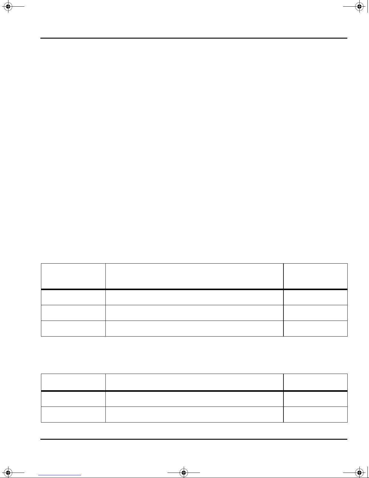
Declaration of Warnings
Throughout this manual, important statements are set off from the main text with an icon
and an associated signal word: “Danger,” “Warning,” “Caution,” or “Note.” The icon and
signal word indicate the severity of the condition or situation. Be sure to read these
statements and take special care to follow the instructions.
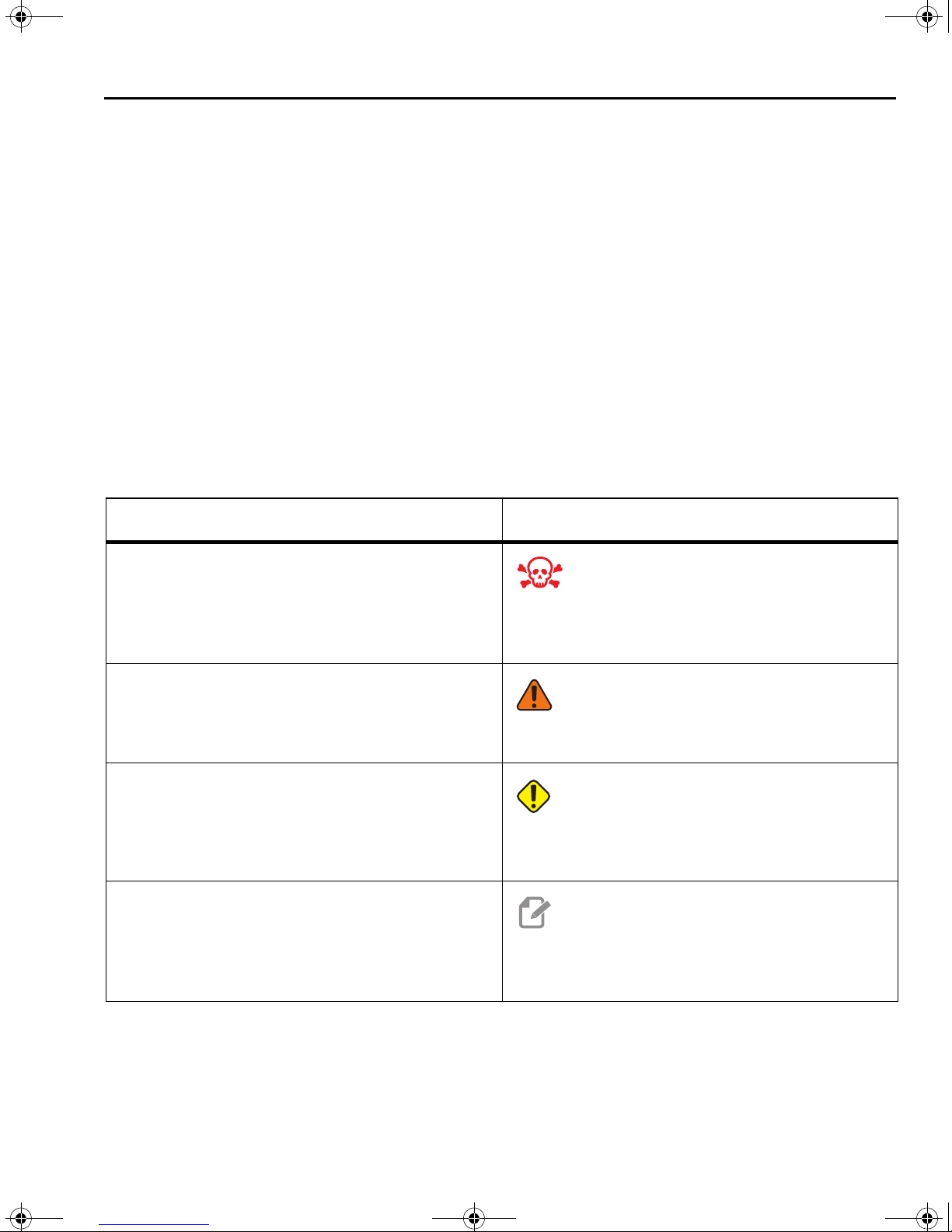
Description Example
Danger means that there is a condition or situation
that will cause death or severe injury if you do not
follow the instructions given.
Warning means that there is a condition or situation
that will cause moderate injury if you do not follow
the instructions given.
Caution means that minor injury or machine
damage could occur if you do not follow the
instructions given. You may also have to start a
procedure over if you do not follow the instructions in
a caution statement.
Note means that the text gives additional
information, clarification, or helpful hints.
DANGER: No step. Risk of electrocution, bodily
injury, or machine damage. Do not climb or stand
on this area.
WARNING: Never put your hands between the
tool changer and the spindle head.
CAUTION: Power down the machine before you
do maintenance tasks.
NOTE: Follow these guidelines if the machine is
equipped with the optional extended
Z-clearance table.
xi
Page 14

96-8913A.book Page xii Monday, May 18, 2015 7:55 AM
Text Conventions Used in this Manual
Description Text Example
Code Block text gives program examples.
A Control Button Reference gives the name of a
control key or button that you are to press.
A File Path describes a sequence of file system
directories.
A Mode Reference describes a machine mode. MDI
A Screen Element describes an object on the
machine’s display that you interact with.
System Output describes text that the machine
control displays in response to your actions.
User Input describes text that you should enter into
the machine control.
Variable n indicates a range of non-negative integers
from 0 to 9.
Press
Service > Documents and Software >...
Select the
PROGRAM END
G04 P1.;
Dnn represents D00 through D99.
G00 G90 G54 X0. Y0.;
[CYCLE START].
SYSTEM tab.
xii
Page 15

96-8913A.book Page xiii Monday, May 18, 2015 7:55 AM
Contents
Chapter 1 Safety . . . . . . . . . . . . . . . . . . . . . . . . . . . . . . . . . . . . 1
1.1 Introduction . . . . . . . . . . . . . . . . . . . . . . . . . . . . . . . 1
1.2 Read Before Operating . . . . . . . . . . . . . . . . . . . . . . . . . 1
1.3 Setup Safety . . . . . . . . . . . . . . . . . . . . . . . . . . . . . . . 3
1.4 Operational Safety . . . . . . . . . . . . . . . . . . . . . . . . . . . . 3
1.5 More Information Online . . . . . . . . . . . . . . . . . . . . . . . . . 4
Chapter 2 Introduction . . . . . . . . . . . . . . . . . . . . . . . . . . . . . . . . . 5
2.1 Features . . . . . . . . . . . . . . . . . . . . . . . . . . . . . . . . . 5
2.2 More Information Online . . . . . . . . . . . . . . . . . . . . . . . . . 6
Chapter 3 Operation . . . . . . . . . . . . . . . . . . . . . . . . . . . . . . . . . . 7
3.1 Bar Feeder Setup . . . . . . . . . . . . . . . . . . . . . . . . . . . . 7
3.1.1 Bar Feeder Positions . . . . . . . . . . . . . . . . . . . 8
3.1.2 Lathe Setup - Workholding . . . . . . . . . . . . . . . . 9
3.1.3 Lathe Setup - Haas Spindle Liners . . . . . . . . . . . . 10
3.1.4 Bar Setup - Load Bars . . . . . . . . . . . . . . . . . . . 11
3.1.5 Bar Setup - Transfer Tray Adjustment . . . . . . . . . . . 13
3.1.6 Bar Setup - Push Rod Installation / Removal . . . . . . . 13
3.1.7 Bar Feed Variable Setup. . . . . . . . . . . . . . . . . . 15
3.1.8 Reference Position Setup . . . . . . . . . . . . . . . . . 17
3.1.9 Bar Setup - Charging Tray Angle Adjustment . . . . . . . 18
3.2 Bar Length Reset Procedure . . . . . . . . . . . . . . . . . . . . . . 18
3.3 More Information Online . . . . . . . . . . . . . . . . . . . . . . . . . 19
Chapter 4 G-Code Reference. . . . . . . . . . . . . . . . . . . . . . . . . . . . . 21
4.1 G105 Servo Bar Command . . . . . . . . . . . . . . . . . . . . . . . 21
4.2 G105 Q Modes . . . . . . . . . . . . . . . . . . . . . . . . . . . . . 23
4.3 More Information Online . . . . . . . . . . . . . . . . . . . . . . . . . 25
Chapter 5 Programming . . . . . . . . . . . . . . . . . . . . . . . . . . . . . . . 27
5.1 Program Examples . . . . . . . . . . . . . . . . . . . . . . . . . . . 27
5.1.1 Example 1 - Cutoff Subprogram . . . . . . . . . . . . . . 28
5.1.2 Example 2 - Cutoff in Program. . . . . . . . . . . . . . . 30
5.1.3 Example 3 - Double Push . . . . . . . . . . . . . . . . . 31
5.2 Counter . . . . . . . . . . . . . . . . . . . . . . . . . . . . . . . . . 33
xiii
Page 16

96-8913A.book Page xiv Monday, May 18, 2015 7:55 AM
5.3 Loading Short Bars . . . . . . . . . . . . . . . . . . . . . . . . . . . 34
5.4 Macro Variables . . . . . . . . . . . . . . . . . . . . . . . . . . . . . 35
5.5 More Information Online . . . . . . . . . . . . . . . . . . . . . . . . . 36
Chapter 6 Maintenance . . . . . . . . . . . . . . . . . . . . . . . . . . . . . . . .37
6.1 Maintenance . . . . . . . . . . . . . . . . . . . . . . . . . . . . . . . 37
6.2 More Information Online . . . . . . . . . . . . . . . . . . . . . . . . . 38
Index. . . . . . . . . . . . . . . . . . . . . . . . . . . . . . . . . . .39
xiv
Page 17

29- 0790A Rev A
WARNING
© 2015 Haas Automation, Inc.
Risk of serious injury.
Machine may start automatically at any time.
Mutilation and crushing will
occur if hands are inside
machine during operation.
Must close cover
before operation.
29- 0790A Rev A
WARNING
© 2015 Haas Automation, Inc.
Risk of serious injury.
Machine may start automatically at any time.
Mutilation and crushing will
occur if hands are inside
machine during operation.
Must close cover
before operation.
96-8913A.book Page 1 Monday, May 18, 2015 7:55 AM
Chapter 1: Safety
1.1 Introduction
Before you work with your Bar Feeder, read this manual and the warning labels on the
machine. Make sure that everyone who uses this equipment understands the hazards
found in and around automatic equipment. Only trained operators should use this machine.
WARNING: The Bar Feeder is controlled by the lathe and may start at any time.
F1.1: Bar Feeder Safety Decal Location
Safety
1.2 Read Before Operating
Do not use the Bar Feeder until you have read all safety instructions, warnings, and
cautions associated with this machine.
Basic safety:
Read and follow all machine maintenance, setup, and operation instructions. Read and
follow spindle liner installation and use instructions.
Electrical safety:
Disconnect the electrical power before you do maintenance tasks.
1
Page 18

96-8913A.book Page 2 Monday, May 18, 2015 7:55 AM
Read Before Operating
Operation Safety:
DANGER: Incorrect setup of the Bar Feeder or spindle liner tubes can cause the
workpiece or rotating parts to be ejected with lethal force, which can
also destroy the machine(s).
• Do not attempt to operate the Bar Feeder until you have received operation and
safety training.
• Keep your body, limbs, and foreign objects out of the machine during operation.
• Make sure that your setup is correct before automatic operation.
• The Bar Feeder is automatically controlled and may start at any time.
• Warn nearby people that an automatic machine is in operation.
• Do not operate the lathe or the Bar Feeder with the door open.
• Immediately replace worn or broken Bar Feeder components or spindle liners.
• Do not modify the Bar Feeder in any way.
• Do not use the Bar Feeder beyond the recommended speed or material
capacity limits.
• Do not use the Bar Feeder without a correctly sized spindle liner installed in the lathe
spindle.
• In the event of vibration or unusual noise, immediately stop the lathe spindle. Do not
operate the machine again until you find and correct the condition that causes the
vibration or noise.
• Do not attach dead stops, bar pilot bushings, or anti-vibration collars to the body of
the rotating union (chuck closing cylinder) of the lathe. Violent, catastrophic failure of
the rotating union can occur at high spindle RPM if attached devices cause damage
to the rotating union.
• Do not operate the spindle while the bar material is unclamped.
• Do not operate the spindle if the bar material extends out of the spindle liner.
• Do not start or continue a machine cycle unless you are certain of the
part-off allowance.
• Damage from incorrect use is not covered under the machine warranty.
• There are no user serviceable parts inside the machine. Contact your dealer for
approved service.
2
Page 19

96-8913A.book Page 3 Monday, May 18, 2015 7:55 AM
1.3 Setup Safety
Refer to the Operation chapter of this manual for more information about setup procedures.
WARNING: Always press [EMERGENCY STOP] on the lathe before you put your
hands inside the Bar Feeder enclosure. Unexpected rapid motion can
occur and cause injury.
Only a trained user may load and adjust the machine to feed bars. During setup, be aware
of these pinch points:
• All parts of the moving mechanism. This includes the pusher assembly, spaces
inside the enclosure, and near the bar lifter and bar positioner arms.
• The area between the bar and the lathe.
• The area between the charging tray and the transfer tray.
• Rolling bar stock can also pinch fingers.
Safety
1.4 Operational Safety
WARNING: The area between the Bar Feeder and the lathe is hazardous. Always
press [EMERGENCY STOP] before you put anything between the Bar
Feeder and the lathe.
Before you run a program, always close the setup lid.
3
Page 20

96-8913A.book Page 4 Monday, May 18, 2015 7:55 AM
More Information Online
1.5 More Information Online
For updated and supplemental information, including tips, tricks, maintenance procedures,
and more, go to www.HaasCNC.com
You can also scan this code with your mobile device to directly access the “Best Practices”
page on the Resource Center, which includes information about safety.
and select the Resource Center.
4
Page 21

2
3
4
5
96-8913A.book Page 5 Monday, May 18, 2015 7:55 AM
Chapter 2: Introduction
2.1 Features
The Haas Bar Feeder has a heavy-duty, compact design, with capacity for bars from 3/8"
(10 mm) to 3 1/8" (79 mm) in diameter. Refer to the Haas web site at www.HaasCNC.com
for more dimensions and information.
Before you use your Haas Bar Feeder, take some time to become familiar with some of the
features that are different from previous-generation Haas Bar Feeders. Refer to the
Operation chapter of this manual for more information on how these features work.
F2.1: Haas Bar Feeder Features Overview
Introduction
1
1. High-Speed, Belt-Driven Bar Pusher: This mechanism quickly, smoothly, and
accurately feeds bar stock into your lathe.
2. Quick-Change Push Rod: Lets you change push rods quickly and easily, without tools
and no need for alignment.
3. Front-Mounted Transfer Tray Height-Adjustment Wheel: Lets you adjust the transfer
tray height on the lathe-spindle end of the Bar Feeder, for faster and easier setup.
4. Setup Mode Release Pedal: Use this pedal to release the Bar Feeder and slide it back
into Lathe Set Up mode.
5. Extruded Spindle Liner Storage Racks: Store your spindle liners here for easy access.
5
Page 22

96-8913A.book Page 6 Monday, May 18, 2015 7:55 AM
More Information Online
2.2 More Information Online
For updated and supplemental information, including the latest revision of this manual, tips,
tricks, maintenance procedures, and more, visit the Haas Resource Center at
diy.HaasCNC.com
to the current manuals on the Resource Center:
. You can also scan the code below with your mobile device to go directly
6
Page 23

1
243
5
6
7
8
9
96-8913A.book Page 7 Monday, May 18, 2015 7:55 AM
Chapter 3: Operation
3.1 Bar Feeder Setup
Bar Feeder setup consists of these tasks:
• Lathe Setup
– Install the correct spindle liner for your application.
– Set up the correct workholding for a bar feed application.
•Bar Setup
– Load the bar stock.
– Adjust the charging tray angle (if necessary).
– Adjust the transfer tray height for the bar diameter.
– Install the correct push rod.
– Set up the bar feed variables.
Operation
F3.1: Bar Feeder Parts Overview
1. Charging Tray
2. Push Rod
3. Set-up Lid Handle
4. Push Rod Storage
5. Load Mechanism
6. Transfer Tray Adjustment Wheel
7. Release Pedal
8. Spindle Liner Storage
9. Bar Pusher
7
Page 24

1
96-8913A.book Page 8 Monday, May 18, 2015 7:55 AM
Bar Feeder Setup
3.1.1 Bar Feeder Positions
Feed / Auto Position: This is the Bar Feeder’s normal operating position. You can
command Bar Feeder motion at reduced speed with the lid open. In this position, you can
set up your bar feed application, check and adjust tray height alignment, and run your
application.
Lockout / Lathe Setup Position: Press the release pedal [1] at the base, and then push
the Bar Feeder back. This mode disables all Bar Feeder motion. With the Bar Feeder in this
position, you have easy access to change spindle liners, clean the coolant collector, or do
other tasks on the lathe spindle.
8
Page 25

A
B
12 3
4
96-8913A.book Page 9 Monday, May 18, 2015 7:55 AM
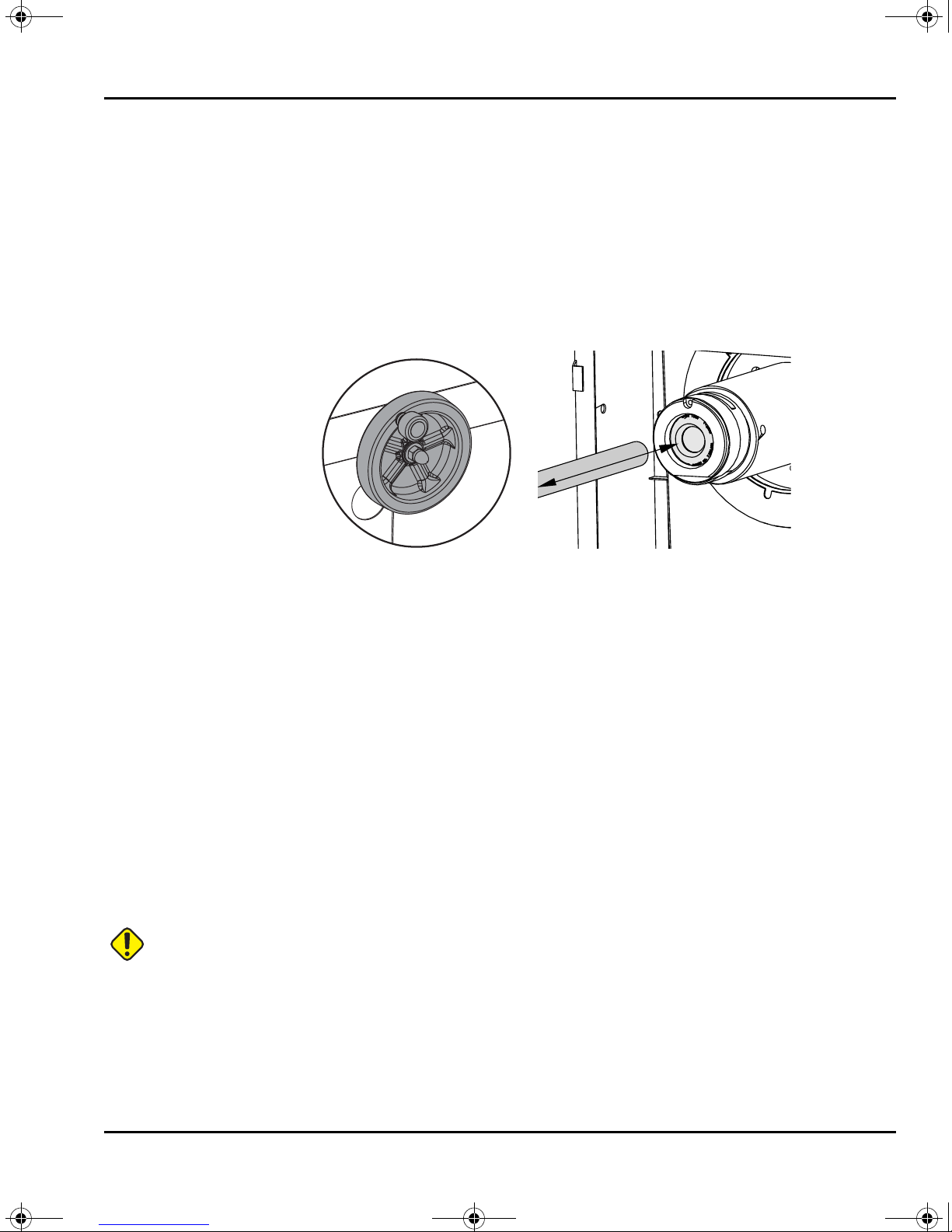
3.1.2 Lathe Setup - Workholding
A drawback collet is required for bar feed applications. The Bar Feeder holds the push rod
in place while the lathe drawtube clamps. If the collet does not pull the bar stock against
the push rod when the drawtube clamps, length variation can occur and accuracy cannot
be guaranteed.
NOTE: Your collet should also have a chamfered lead-in for smooth bar
feeding.
F3.2: Drawback Collet Example. [A] Collet Unclamped; [B] Collet Clamped. [1] Chamfered
Collet Lead-In, [2] Collet Closer Body, [3] Collet, [4] Bar Stock
Operation
For installation instructions, refer to the Lathe Operator’s Manual and the documentation
that came with your workholding.
9
Page 26
AD0020AD0021
96-8913A.book Page 10 Monday, May 18, 2015 7:55 AM
Bar Feeder Setup
3.1.3 Lathe Setup - Haas Spindle Liners
Spindle liners adapt the size of your spindle bore to fit the bar stock that you process. This
lets the bar stock feed and run smoothly. Properly fit spindle liners also help to reduce
vibration and bar whip.
NOTE: Spindle liners do not grip the bar stock. If you have problems with
vibration or poor surface finish in your application, check the clearance
between the bar and the liner. Use a closer-fitting liner if possible.
Put the Bar Feeder in the Lathe Setup position to install spindle liners.
Haas manufactures (2) types of spindle liners; extruded spindle liners, which fit most Haas
lathes, and a bar-guide-and-spacer spindle liner system for 4"-bar-capacity lathes. The
installation instructions for both liner types are available in the online Haas Resource
Center. To retrieve the instructions:
1. Go to www.HaasCNC.com
2. Select the “Search by AD Number” option.
3. Type the number of the document you want to see:
• For the extruded spindle liner kit, use AD0021.
• For the bar-guide-and-spacer kit, use AD0020.
4. Select “Apply”.
You can use the codes below to access the instructions directly on your mobile device.
and select the Resource Center.
10
Page 27

96-8913A.book Page 11 Monday, May 18, 2015 7:55 AM
Lathe Setup - Other Spindle Liners
Haas extruded spindle liners are designed to fit a wide range of bar stock sizes, and their
one-piece finned design helps keep the bar stock centered in the spindle. If you use the
bar-guide-and-spacer system or another spindle liner, remember these points:
• The liner passage for the bar must fit the bar as closely as possible while still letting
the bar move through smoothly. The larger your bar stock is in diameter, the closer
the liner must fit.
• The liner must be centered in the spindle.
• Make custom liners or bar-guide disks with a generous lead-in chamfer. The Haas
bar-guide disks use a 0.25" chamfer at 45 degrees.
3.1.4 Bar Setup - Load Bars
Make sure that the bars you use are appropriate for your setup:
Operation
• Test the fit of the bar stock in the spindle liner. The liner must fit close but be large
enough to let the bar pass through freely. Use a different liner if necessary.
• To determine the minimum bar length: Measure the gap between the end of the
transfer tray and the lathe spindle liner. Multiply this distance by 2.25. Each bar must
be at least as long as the result. For example, if the distance between the end of the
transfer tray and the lathe spindle is 6.75" (171 mm), each bar must be at least 15.2"
(386 mm) long.
• Bar stock must be straight.
• Add a chamfer to the leading end of the bar for better initial feeding. The leading end
of the bar should have no sharp edges.
• Bar stock must be cut square on the end that contacts the bar pusher, to prevent
protrusions or length variation.
• The bar stock should not extend outside of the spindle liner.
• Large-diameter, heavy bar stock must be shorter than 36" (813 mm).
• It is good practice to wipe the bars clean before you load them. Dirt and debris
increase liner wear and could also become jammed inside the liner.
Load bars, one at a time, into the charging tray in a single layer. Push shorter bars toward
the lathe. Do not let the bars stack. If the bars roll over each other as you load them, adjust
the charging tray to a shallower angle.
11
Page 28

2
96-8913A.book Page 12 Monday, May 18, 2015 7:55 AM
Bar Feeder Setup
F3.3: Bar Loading Example. [1] Align the Leading Ends of the Bars with the Edge of the Tray. [2]
Do Not Stack the Bars.
1
Hexagonal Bar Stock
If you use hexagonal bar stock:
• Hexagonal liners are highly recommended. They should maintain a consistent
orientation inside the spindle.
• If you use the bar-guide-and-spacer style of spindle liners, the first (2) guide disks
should have hexagonal holes, oriented with the collet.
• The V-shape of the transfer tray keeps hexagonal stock in a consistent orientation.
• The lead end of the bar should have a 30-degree chamfer.
• Use M19 commands to set the spindle orientation to align the collet flats with the bar
flats. in the bar feeder tray. Note that the spindle orientation option is necessary to
do this.
12
Page 29
96-8913A.book Page 13 Monday, May 18, 2015 7:55 AM
3.1.5 Bar Setup - Transfer Tray Adjustment
The transfer tray provides the bar stock a path that leads into the lathe spindle. When your
Bar Feeder was installed, the service technician adjusted the Bar Feeder height to align the
lathe spindle with the adjustment range of the transfer tray. With this procedure, you raise
or lower the transfer tray to adjust it for the bar diameter.
1. Press [EMERGENCY STOP] on the lathe.
2. Put the Bar Feeder in the Feed/Auto position.
3. Put a piece of bar stock in the transfer tray.
Operation
4. Use the wheel to adjust the transfer tray height. Turn it clockwise to raise the tray and
counterclockwise to lower the tray. As you adjust the transfer tray height, move the
bar into the spindle liner by hand. Continue to adjust the transfer tray height until the
bar slides freely into the liner.
5. Make sure that the collet is set for the diameter of the loaded bar:
a. With the collet open and the spindle stopped, slide the bar into the spindle liner
and collet by hand, and check for misalignment, binding or interference.
b. Remove the bar and place it in the charging tray.
3.1.6 Bar Setup - Push Rod Installation / Removal
The Bar Feeder comes with push rods that are 3/4" and 3/8" in diameter. Use the 3/8" push
rod for all round stock material that is smaller than 0.8" (20 mm) in diameter. Use the 3/4"
push rod for material 0.8" (20 mm) in diameter and larger.
CAUTION: Do not use the 3/8" push rod to push bars larger than 0.8" in diameter.
The push rod can bend.
To change the push rod:
1. Press [EMERGENCY STOP] on the lathe. Open the set-up lid.
2. At the lathe end of the push rod, slide the bushing retainer away from the push rod.
13
Page 30
1
1
96-8913A.book Page 14 Monday, May 18, 2015 7:55 AM
Bar Feeder Setup
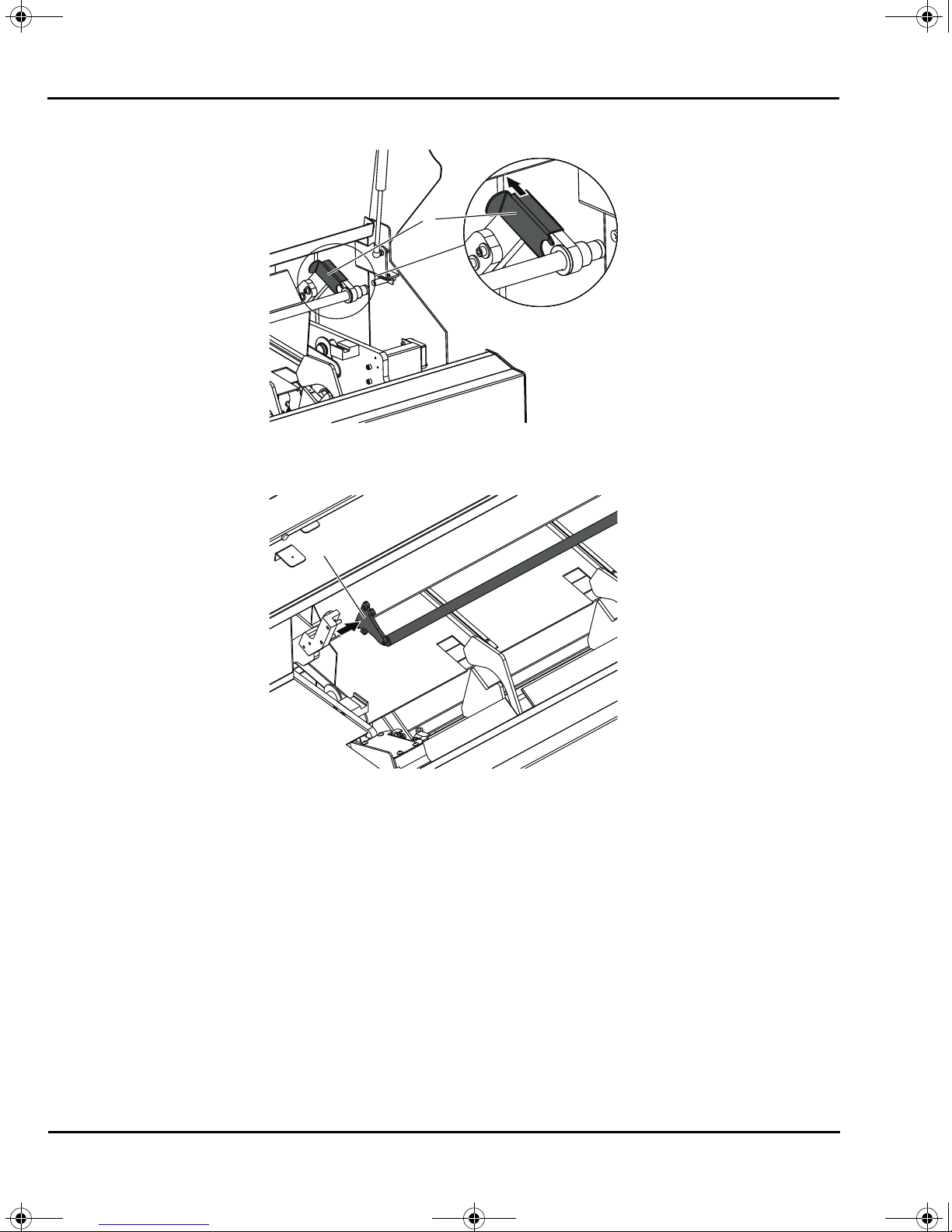
F3.4: Bushing Retainer [1]
3. At the other end of the push rod, pull the retention blade off of the holder block.
F3.5: Retention Blade [1]
4. Remove the push rod. Follow this procedure in reverse to install the other push rod.
5. Store the unused push rod under the set-up lid.
6. Close the lid and reset [EMERGENCY STOP] to resume operation.
14
Page 31
A
#3102 #3101
B
C
D
#3100
96-8913A.book Page 15 Monday, May 18, 2015 7:55 AM
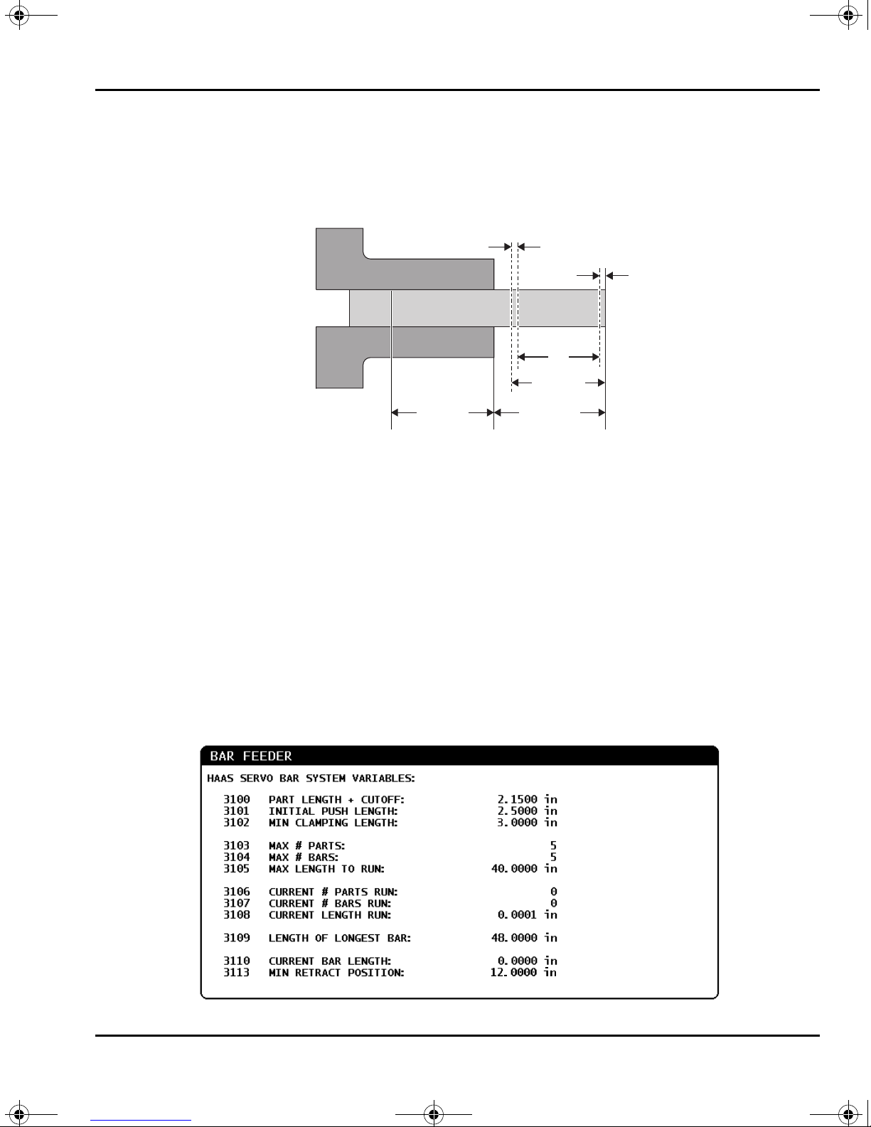
3.1.7 Bar Feed Variable Setup
When you set up your bar feed application, you define the push lengths with variables.
F3.6: Bar Feed Variables Example. Dimensions are not to scale. [A] Reference Point, [B]
Finished Part Length, [C] Facing Allowance, [D] Cutoff Allowance
Operation
• #3100 (Part Length + Cutoff): This is the total length of the finished part, plus
allowances for face clean-up and part-off cuts. This is the distance that the Bar
Feeder pushes the bar on every push after the initial push.
• #3101 (Initial Push Length): The distance the Bar Feeder pushes the material past
the reference point (refer to page 17). The examples given in this manual use a
reference point at the collet face. This is the distance that the Bar Feeder pushes
each new bar for the first time.
• #3102 (Minimum Clamping Length): The minimum length of bar necessary to safely
clamp and machine the workpiece. This is also called the remnant length, but the
actual remnant can be longer.
To set up the variable positions:
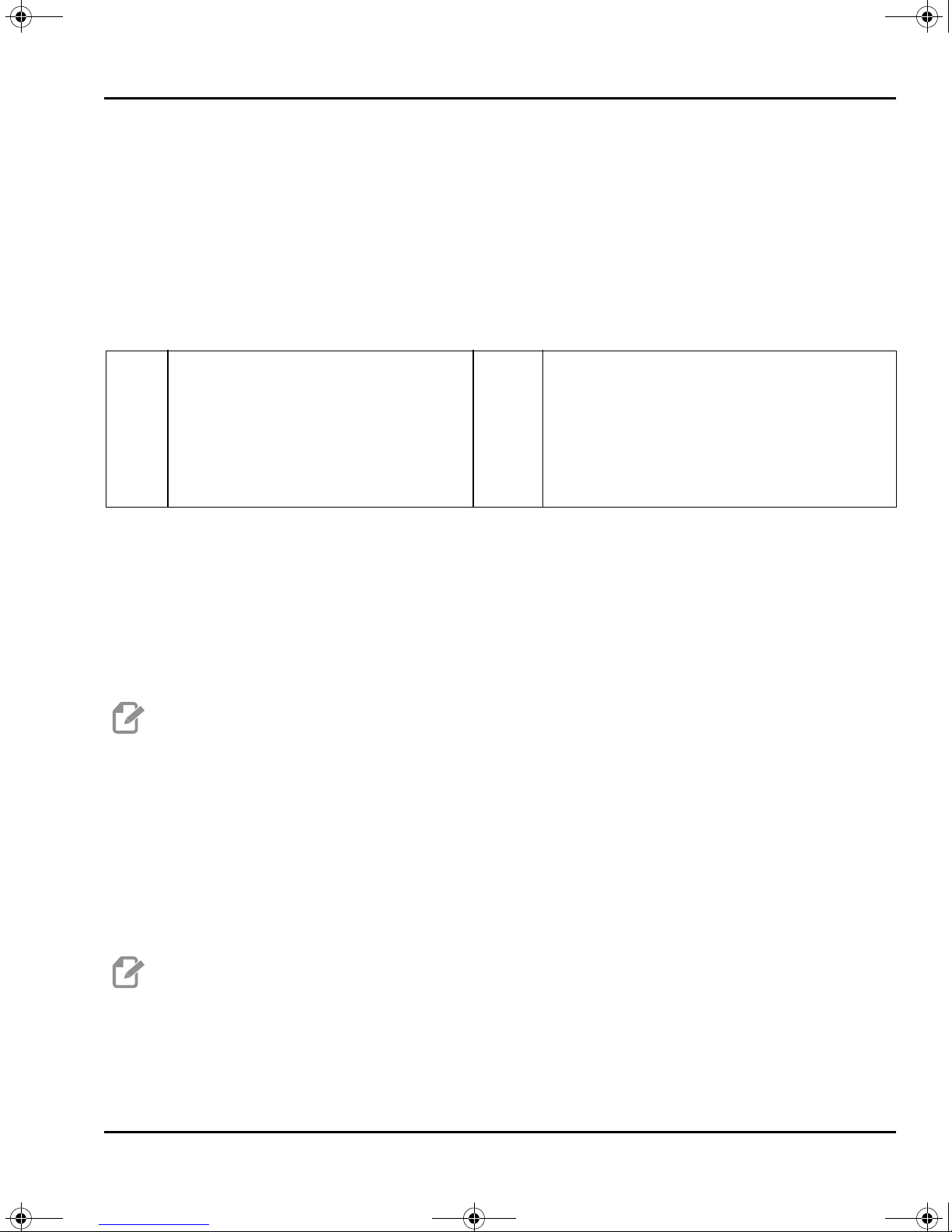
1. Press [CURRENT COMMANDS].
F3.7: Bar Feeder Current Commands Display
15
Page 32

Min. 1/4"
(6.4mm)
1
2
3
96-8913A.book Page 16 Monday, May 18, 2015 7:55 AM
Bar Feeder Setup
2. Press [PAGE UP] or [PAGE DOWN] to find the BAR FEEDER page.
3. Highlight the variable that you want to edit.
4. Type the value and press [ENTER].
Example:
#3100=2.150 (2.0" long part + 0.125" cutoff tool width + 0.025" facing allowance)
#3101=2.5 (2.5" of stock pushed past face of the collet)
#3102=3.0 (3.0" of material to clamp. During subsequent bar feeds, the machine will not
push the bar farther than a safe clamp position.)
Push Rod Clearance for #3102
CAUTION: Make sure that the push rod maintains 1/4" (6.4 mm) of clearance
between it and the collet chamfer. This clearance is necessary to
make sure that the push rod does not come in contact with collet
clamping surfaces.
To set push rod clearance:
1. Set macro variable #3102 MIN CLAMPING LENGTH to 1/4" (6.4 mm) from the collet
clamping surfaces.
F3.8: Minimum Clamping Length: [1] Push Rod, [2] Collet, [3] Workpiece
CAUTION: This diagram is for reference only. Workholding varies in form and
function. It is your responsibility to keep the push rod 1/4" away from
workholding surfaces.
16
Page 33

96-8913A.book Page 17 Monday, May 18, 2015 7:55 AM
3.1.8 Reference Position Setup
The reference position is the zero point that the Haas Bar Feeder uses for all push
operations. You usually establish the reference point at the face of the collet or the chuck
jaws.
NOTE: You must reset the reference position each time you change the
workholding or move the Bar Feeder. When you change jobs, you do
not need to establish a new reference position unless the new job uses
different workholding.
To set up the reference position:
1. If there is a workpiece in the lathe, remove it.
2. Make sure the lathe door and the set-up lid are closed.
Operation
3. Type G105 Q4 ; in MDI mode, and then press [CYCLE START].
The Bar Feeder loads a bar and pushes it toward the face of the collet.
4. After machine motion stops, press [RESET]. You can now use the jog handle to
move the Bar Feeder.
5. Jog the material to the reference position that you want to use, usually flush with the
collet face.
6. Clamp the workholding.
7. Make sure the lathe door and the set-up lid are closed.
8. Command G105 Q2 ; (Set Reference Position).
The machine records the position, then pushes the bar the distance specified in
variable #3101 (Initial Push Length). In the variable setup described above, this is
2.5" past the reference point.
9. Measure the bar to make sure that the Bar Feeder pushed the stock the correct
distance.
17
Page 34

1
96-8913A.book Page 18 Monday, May 18, 2015 7:55 AM
Bar Length Reset Procedure
3.1.9 Bar Setup - Charging Tray Angle Adjustment
The charging tray holds the supply of bar stock for the load fingers to pick up and move
onto the transfer tray. Use the adjustment handle under the tray to adjust the tray angle.
F3.9: [1] Charging Tray Angle-Adjustment Handle
1. Turn the adjustment handle under the charging tray to adjust the feed angle. For
most round stock, the charging tray angle should be approximately 5 degrees above
horizontal.
2. Type this test program into the lathe control and watch the Bar Feeder operation.
Make sure that bars feed reliably from the tray into the feed mechanism. You do not
need to include the comments in parentheses:
G105 Q9 (Load Bar Stock) ;
G105 Q8 (Unload Bar Stock) ;
3. If necessary, adjust the tray angle. Increase the angle if the bars do not feed reliably.
Decrease the angle if the bars stack.
3.2 Bar Length Reset Procedure
If a bar feed does not complete successfully because of an EMERGENCY STOP or an
alarm, the Bar Feeder can lose the current bar length and you need to reset it.
1. Enter MDI mode.
2. Press [V], and then [HANDLE JOG].
3. Use the jog handle to control the V Axis until the bar is at the reference position.
4. Type G105 Q1 ; in MDI, and then press [CYCLE START].
This resets the bar length and pushes the bar to its initial push-out length.
18
Page 35

96-8913A.book Page 19 Monday, May 18, 2015 7:55 AM
3.3 More Information Online
For updated and supplemental information, including the latest revision of this manual, tips,
tricks, maintenance procedures, and more, visit the Haas Resource Center at
diy.HaasCNC.com
to the current manuals on the Resource Center:
Operation
. You can also scan the code below with your mobile device to go directly
19
Page 36

96-8913A.book Page 20 Monday, May 18, 2015 7:55 AM
More Information Online
20
Page 37

96-8913A.book Page 21 Monday, May 18, 2015 7:55 AM
Chapter 4: G-Code Reference
4.1 G105 Servo Bar Command
This is the G-code used to command a Bar Feeder.
G105 [In.nnnn] [Jn.nnnn] [Kn.nnnn] [Pnnnnn] [Rn.nnnn]
I - Optional Initial Push Length (macro variable #3101) Override (variable #3101 if I is not
commanded)
J - Optional Part Length + Cutoff (macro variable #3100) Override (variable #3100 if J is
not commanded)
K - Optional Min Clamping Length (macro variable #3102) Override (variable #3102 if K is
not commanded)
P - Optional cutoff subprogram
Q - Bar Feeder setup mode
R - Optional spindle orientation for new bar
I, J, K are overrides to macro variable values listed on the Current Commands Page. The
control applies the override values only to the command line in which they are located. The
values stored in Current Commands are not modified.
When you command G105, the Bar Feeder does one of these operations, based on the
length of the current bar and the value of MINIMUM CLAMPING LENGTH (#3102 or K)
added to PART LENGTH + CUTOFF (#3100 or J):
G-Code Reference
1. If the current bar is long enough to correctly clamp and machine a new part (the bar
is longer than MINIMUM CLAMPING LENGTH plus PART LENGTH + CUTOFF):
a) If there is a P value in the G105 block, the control runs the cutoff subprogram.
b) The spindle stops.
c) The workholding unclamps.
d) The Bar Feeder pushes the bar the distance specified in PART LENGTH +
CUTOFF (#3100) or, if the G105 block has a J value, the distance specified by
J.
e) The workholding clamps and the program continues.
2. If the current bar is too short to correctly clamp and machine a new part (the bar is
shorter than MINIMUM CLAMPING LENGTH plus PART LENGTH + CUTOFF):
a) If there is a P value in the G105 block, the control runs the cutoff subprogram.
b) The spindle stops.
c) The workholding unclamps, and the pushrod moves to the unloaded position.
d) If the G105 block has an R value, the spindle orients.
e) The Bar Feeder loads a new bar and pushes it the distance specified by
INITIAL PUSH LENGTH (#3101) or, if the G105 block has an I
distance specified by I. If #3101 and I have values of zero, the Bar Feeder
pushes the bar the distance specified by REFERENCE POSITION (#3112).
value, the
21
Page 38

96-8913A.book Page 22 Monday, May 18, 2015 7:55 AM
G105 Servo Bar Command
f) The workholding clamps.
g) If there is a P value in the G105 block, the control runs the cutoff subprogram,
unclamps the workholding, then pushes the bar the distance specified by
#3100 or J, then clamps the workholding.
h) The program continues.
If the Bar Feeder cannot complete a bar feed operation because of an alarm or
[EMERGENCY STOP], the system stops and displays the message Check Bar
Position. If you are confident that the bar position is correct, press [CYCLE START] to
continue. If you are not confident that the bar position is correct, refer to the bar length reset
procedure on page 18.
22
Page 39
96-8913A.book Page 23 Monday, May 18, 2015 7:55 AM
4.2 G105 Q Modes
Q modes are special Bar Feeder commands that you use with a G105 command in MDI
mode. They are generally for setup and troubleshooting purposes. This section describes
the available Q modes.
To use a Q mode, type G105 QX ; in MDI mode, where X is the Q mode number you want
to command, and then press [CYCLE START].
T4.1: Q Mode List
G-Code Reference
Q0
Q1
Q2
Q3
Q4
Q5
Q6
Normal Bar Feed
Set the Bar Length
Set the Reference Position
Alternate Set Reference Position
Jog to the Reference Position
Set the End-of-Bar Position
Unload the Push Rod
Q7
Q8
Q9
Q10
Q11
Q12
Load the Push Rod
Unload the Bar Stock
Load the Bar Stock
Load Bar and Measure
Bump Load Push Rod Direction
Bump Load Bar Direction
G105 Q0 - Normal Bar Feed: Use this to command a normal bar feed in MDI mode. This
is the same as a G105 command with no Q mode.
G105 Q1 - Set the Bar Length: Use this command to reset the bar length stored in the
control. You can use this for bars that are too short to load, or for recovery after an error.
Press [V] and then [HANDLE JOG], then use the jog handle to push the bar to the
reference position. Clamp the workholding and run this command to recalculate the bar
length.
NOTE: The push rod must be in contact with the bar when you set the bar
length. If the bar is pushed out too far, jog the push rod back, push the
bar against it by hand and then jog the bar to the reference point.
G105 Q2 [I] - Set the Reference Position, then Initial Push: This command sets the
reference position, unclamps the workholding and then pushes the bar the distance
specified in the Initial Push Length variable (#3101), or the I value if given, then clamps
the workholding. It then runs the cutoff subprogram (PXXXXX) if specified. You must
command G105 Q4 before you can use this command.
NOTE: The push rod must be in contact with the bar when you set the
reference position. If the bar is pushed out too far, jog the push rod
back, push the bar against it by hand and then jog the bar to the
reference point.
23
Page 40

96-8913A.book Page 24 Monday, May 18, 2015 7:55 AM
G105 Q Modes
G105 Q3 - Set the Reference Position from the Bar Face: This command subtracts the
Part Length + Cutoff variable (#3100) from the current bar face position to set the
reference position. It then runs the cutoff subprogram (PXXXXX), if specified. Refer to the
description of G105 Q2 for other considerations. You must command G105 Q4 before
you can use this command.
WARNING: This command does not cause the bar to move. If you execute this
command more than once, it moves the reference position farther
away from the bar face, and possibly out of the clamping area. If the
bar is not clamped when the spindle starts, severe damage will occur.
G105 Q4 [R] - Jog to the Reference Position: This command loads a bar, measures it,
and then pushes it through the spindle. It stops just before the chuck face. Press RESET
to use the V-Axis handle jog mode to jog the bar to the reference position.
G105 Q5 - Set the End-of-Bar position: This command sets the switch position that the
control uses to determine bar lengths. This value is stored in variable #3111. The service
technician establishes this value during installation. It is necessary to reset this variable
only if its value is lost.
G105 Q6 - Unload the Push Rod: This command causes the bar feeder to remove the
push rod from the bar pusher. It then lifts the push rod into the storage position.
G105 Q7 - Load the Push Rod: This command causes the bar feeder to move the push
rod onto the bar pusher.
G105 Q8 - Unload the Bar: This command causes the Bar Feeder to remove a bar from
the transfer tray and put it in the charging tray. Make sure that the bar is within the space
of the charging tray before you execute this command.
G105 Q9 - Load Bar: This command causes the Bar Feeder to load a bar from the charging
tray and put it in the transfer tray.
G105 Q10 - Load Bar and Measure: This command loads a bar from the charging tray to
the transfer tray, then measures it. You use this command to check the end-of-bar switch
position. Put a bar of known length in the charging tray. Command G105 Q10, and
compare the actual bar length to the value in variable #3110.
G105 Q11 - Bump Load Push Rod Direction: Used for assembly access only. Bumps
the bar transfer mechanism toward the charging tray.
G105 Q12 - Bump Load Bar Direction: Used for assembly access only. Bumps the bar
transfer mechanism away from the charging tray.
24
Page 41

96-8913A.book Page 25 Monday, May 18, 2015 7:55 AM
4.3 More Information Online
For updated and supplemental information, including the latest revision of this manual, tips,
tricks, maintenance procedures, and more, visit the Haas Resource Center at
diy.HaasCNC.com
to the current manuals on the Resource Center:
G-Code Reference
. You can also scan the code below with your mobile device to go directly
25
Page 42

96-8913A.book Page 26 Monday, May 18, 2015 7:55 AM
More Information Online
26
Page 43
96-8913A.book Page 27 Monday, May 18, 2015 7:55 AM
Chapter 5: Programming
5.1 Program Examples
This section has (3) program examples.
• Example 1 calls a subprogram in the G105 command to cut off the part. This
programming style is most appropriate for solid stock where the cutoff program must
cut to the centerline.
• Example 2 includes the cutoff in the part program. This programming style is most
appropriate when the finished part has a hole through the center, and the cutoff
program does not have to cut to the centerline.
• Example 3 describes a double push. This programming style is most appropriate to
machine a length of bar shorter than the full part length, and then push to the full part
length.
Programming
CAUTION: The sample programs in this manual have been tested for accuracy,
but they are for illustrative purposes only. The programs do not define
tools, offsets, or materials. They do not describe workholding or other
fixturing. If you choose to run a sample program on your machine, do
so in Graphics mode. Always follow safe machining practices when
you run an unfamiliar program.
27
Page 44

96-8913A.book Page 28 Monday, May 18, 2015 7:55 AM
Program Examples
5.1.1 Example 1 - Cutoff Subprogram
This example shows the preferred programming method with solid stock material, where
the cutoff operation must cut to the centerline. The material is 2" (51mm) diameter solid
stock and the finished part is 1" (25mm) long. The cutoff tool is 0.125" wide. The spindle/tool
clearance is 0.875". The amount of stock to remove from the face is 0.025".
The program uses these Bar Feeder variable values:
Variable
Number Description Value
#3100 Part Length + Cutoff Allowance + Facing Allowance 1.150
#3101 Initial Push Length 1.025
#3102 Minimum Clamping Length 1.0
Command G105 in MDI mode to load a bar and push it to the initial push length. In this
example, the initial push length includes the 0.875" spindle/tool clearance, the 0.125" width
of the cutoff tool, and a 0.025" facing allowance.
This program starts with a call to the cutoff subprogram. The effect of this is different
depending on whether this is a new bar or if it is the next program loop on a bar:
• If this is a new bar, the cutoff subprogram faces and cleans the bar end at the initial
push length (#3101), and then the Bar Feeder pushes out the part length plus
allowances (#3100).
• When the subprogram call repeats on a bar, the cutoff subprogram cuts off finished
parts and leaves a clean bar end, and then the Bar Feeder pushes out the part length
plus allowances (#3100).
NOTE: When you write a bar feed program with a cutoff routine and then a bar
feed command, or with a bar feed command that includes a Pxxxxx
cutoff subprogram call, it is safest and most consistent to start the
program with the bar feed command. This practice makes sure that a
fresh piece of material, with a faced surface, in a consistent position,
is always available for the rest of the operation.
28
Page 45

#3100
#3102
A
0.875"
0.125" 1.0"
X0, Z0
#3102
A
#3101
12
96-8913A.book Page 29 Monday, May 18, 2015 7:55 AM
Note also that the main program has a block-deleted M99 command in the second-to-last
line. This lets you turn on block delete if you want the program to run only (1) time.
%
O00023 (PART PROGRAM)
G105 P24 (CALL CUTOFF SUB PROGRAM THEN BAR FEED)
T303 (FACE & TURN)
G50 S1500
G96 S500 M03
G00 G54 X2.1 Z0 M08
G01 X-0.05 F0.005
G00 X1.95 Z.05
G01 Z-1.0 F0.01
X2.1
G53 G00 X0
G53 Z0
/M99
M30
%
%
O00024 (CUT-OFF SUB PROGRAM)
T404
G50 S1500
G96 S500 M03
G00 X2.1 Z0.1 M08
Z-1.125 (1" PART LENGTH PLUS THE TOOL WIDTH)
G01 X-0.05 F0.005
G00 X2.1
G53 X0
G53 Z0
M99
%
Programming
F5.1: Program Example 1. Dimensions are not to scale. [1] Shows the Bar After the Initial Push
at MDI Setup, [2] Shows the Bar During Subsequent Feeds, [A] Reference Point,
Variables as Defined Above.
29
Page 46
96-8913A.book Page 30 Monday, May 18, 2015 7:55 AM
Program Examples
5.1.2 Example 2 - Cutoff in Program
This example shows the preferred programming method when the cutoff operation does
not have to cut to the centerline, as when the finished part has a hole through the center.
Unlike the first program example, which uses the same subprogram to both face a new bar
and cut off finished parts, this program includes a facing operation for a new bar, and a
separate cutoff operation for finished parts. The facing operation cuts to the workpiece
centerline. To save machining time, the cutoff operation cuts only as far as the finished
part’s inner diameter.
The material is 2" (51 mm) diameter solid stock and the finished part is 1" (25 mm) long.
The cutoff tool is 0.125" wide. The spindle/tool clearance is 0.875". The amount of stock to
remove from the face is 0.025".
The program uses these Bar Feeder variable values:
Variable
Number Description Value
#3100 Part Length + Cutoff Allowance + Facing Allowance 1.150
#3101 Initial Push Length 2.0
#3102 Minimum Clamping Length 1.0
Command G105 in MDI mode to load a bar and push it to the initial push length. In this
example, the initial push length includes the 1" finished part length, 0.875" spindle/tool
clearance, the 0.125" width of the cutoff tool, and a 0.025" facing allowance.
This program starts with the face and turn operation, then the cutoff operation, and the bar
feed command at the end.
Note also that the program has a block-deleted M99 command in the second-to-last line.
This lets you turn on block delete if you want the program to run only (1) time.
% ;
O00020 (PART PROGRAM) ;
T303 (FACE & TURN) ;
G50 S1500 ;
G96 S500 M03 ;
G00 G54 X2.1 Z0 M08 ;
G01 X-0.05 F0.005 ;
G00 X1.95 Z.05 ;
G01 Z-1.0 F0.01 ;
X2.1 ;
G53 G00 X0 ;
G53 Z0 ;
T404 (CUT OFF OPERATION) ;
G50 S1500 ;
30
Page 47
96-8913A.book Page 31 Monday, May 18, 2015 7:55 AM
G96 S500 M03 ;
G00 X2.1 Z0.1 M08 ;
Z-1.125 (1" PART LENGTH PLUS THE TOOL WIDTH) ;
G01 X-0.05 F0.005 ;
G00 X2.1 ;
G53 X0 ;
G53 Z0 ;
G105 (BAR FEED) ;
/M99 ;
M30 ;
%
5.1.3 Example 3 - Double Push
This example demonstrates a double push on the workpiece. The program contains (2)
G105 commands. The first G105 uses the variables values set on the Bar Feeder current
commands page. The second G105 uses J and K values to override the variable values.
This is the preferred programming method when, for example, you need the rigidity of a
short bar for part of your operation, and then to machine the rest of the longer finished part.
The material is 2" (51 mm) diameter solid stock and the finished part is 4" (100 mm) long.
The cutoff tool is 0.125" wide. The spindle/tool clearance is 0.875". The amount of stock to
remove from the face is 0.025".
The program uses these Bar Feeder variable values. These values apply to the first G105
command, given without address codes:
Programming
Variable
Number Description Value
#3100 Part Length + Cutoff Allowance + Facing Allowance 1.150
#3101 Initial Push Length 2.025
#3102 Minimum Clamping Length 4.0
In the second G105 command, the program uses these address codes to override the
values given in the bar feeder variables:
Address Code Description Value
J Part Length + Cutoff Allowance + Facing Allowance 3.0
K Minimum Clamping Length 1.0
31
Page 48

96-8913A.book Page 32 Monday, May 18, 2015 7:55 AM
Program Examples
Note also that the program has a block-deleted M99 command in the second-to-last line.
This lets you turn on block delete if you want the program to run only (1) time.
Command G105 in MDI mode to load a bar and push it to the initial push length. In this
example, the initial push length includes the 2" length to machine first and a 0.025" facing
allowance.
Before you run this program for the first time after you load a bar in MDI mode, move the
cursor to the block after the first G105 command in the program to bypass the first push.
Remember that after the initial push, the bar is already in position to start machining.
%
O00021 (DOUBLE PUSH WITH Bar Feeder) ;
G105 (BAR FEED USING MACRO VARIABLES) ;
T303 (FACE & TURN) ;
M01 ;
G50 S1500 ;
G96 S500 M03 ;
G00 G54 X2.1 Z0 M08 ;
G01 X-0.05 F0.005 ;
G00 X1.95 Z.05 ;
G01 Z-1.0 F0.01 ;
X2.1 ;
G53 G00 X0 ;
G53 Z0 ;
G105 J3.0 K1.0 (BAR FEED WITH OPTIONAL VARIABLES) ;
M01 ;
T404 (CUT OFF TOOL) ;
G55 (WORK OFFSET CHANGE) ;
G50 S1500 ;
G96 S500 M03 ;
G00 G55 X2.1 Z0.1 M08 ;
Z-4.125 ;
G01 X-0.05 F0.005 ;
G00 X2.1 ;
G53 X0 ;
G53 Z0 ;
/M99 ;
M30 ;
%
32
Page 49

96-8913A.book Page 33 Monday, May 18, 2015 7:55 AM
5.2 Counter
The Bar Feeder can count either the numbers of bars used, the number of parts made, or
the length of material run. A non-zero value set in Max # Parts (#3103), Max # Bars
(#3104), or Max Length to Run (#3105) determines the active counting modes. The
first non-zero value stops the cycle if more than one is present.
To stop the machine after a chosen number of parts, set Current Number of Parts
Run (#3106) to zero. Then, set Max # Parts (#3103) to the chosen quantity. The counter
increments at each G105 command. If G105 is at the beginning of the program, the counter
increments before each part starts machining. If G105 is at the end of the program, the
counter increments after each part finishes machining.
To stop the machine after a certain number of bars, set Current Number of Bars Run
(#3107) to zero. Then set Max # Bars (#3104) to the number of bars to run. The counter
increments as each bar is loaded.
To stop the machine after a certain length of bar, set Current Length Run (#3108) to
zero. Then set Max Length To Run (#3105) to the total bar length you want to machine.
Programming
NOTE: The counter increments by the push distance at each G105
command. This distance is either the initial push length (#3101) after
a bar is loaded or the part length + cutoff (#3100) at each bar feed
after the initial push.
33
Page 50

96-8913A.book Page 34 Monday, May 18, 2015 7:55 AM
Loading Short Bars
5.3 Loading Short Bars
F5.2: Short Bars Must Use At Least (2) Pick Arms
To machine short bars:
1. When you load short bars on the charging tray, make sure that at least (2) of the pick
arms pick the bar up, or the bar may not load properly.
NOTE: The actual minimum bar length depends on your setup. Refer to
page 11 for a description of the process to determine your minimum
bar length.
2. Push all of the bars against the side of the charging tray closest to the lathe.
3. Enter the length of the longest bar in the tray into macro variable #3109 on the BAR
FEEDER Current Commands page.
The bar pusher rapids to the buffer position before it slows to measure the bar length.
34
Page 51

96-8913A.book Page 35 Monday, May 18, 2015 7:55 AM
5.4 Macro Variables
T5.1: Bar Feeder Macro Variables
Variable Name Description
#3100 PART LENGTH + CUTOFF Bar feed increment (Length of bar pushed out with each G105
#3101 INITIAL PUSH LENGTH Initial bar feed length (Length of bar pushed out past the
#3102 MIN CLAMPING LENGTH Minimum length for clamping (Length of bar required to support
Programming
after the bar is loaded). Finished part length + cutoff length +
face cleanup allowance.
reference position when loaded).
the length pushed past the collet face).
#3103 MAX # PARTS Maximum number of parts.
#3104 MAX # BARS Maximum number of bars.
#3105 MAX LENGTH TO RUN Maximum length to run.
#3106 CURRENT # PARTS RUN Part counter.
#3107 CURRENT # BARS RUN Bar counter.
#3108 CURRENT LENGTH RUN Length counter.
#3109 LENGTH OF LONGEST
BAR
#3113 MIN RETRACT POSITION Adjust this to make sure the push rod retracts out of the spindle
Length of the longest bar (set to 48, if unknown). Setting the
length close to the size of the bar stock allows faster
measurement of shorter bars. This length must be longer than
the bar stock being used.
liner after each G105 push. Jog the V Axis until there is a safe
gap between the end of the push rod and the spindle liner
(approximately 1 inch/25 mm). Look at your V-Axis position, it
will be a negative number (example: -13.0). Enter this number,
as a positive value under variable #3113 (example:
#3113=13.0).
#3110
(Read Only)
#3112
(Internal
Only)
CURRENT BAR LENGTH Current bar length measured by the machine.
REFERENCE POSITION Established using G105 Q4 Jog To Reference Position
35
Page 52

96-8913A.book Page 36 Monday, May 18, 2015 7:55 AM
More Information Online
5.5 More Information Online
For updated and supplemental information, including the latest revision of this manual, tips,
tricks, maintenance procedures, and more, visit the Haas Resource Center at
diy.HaasCNC.com
to the current manuals on the Resource Center:
. You can also scan the code below with your mobile device to go directly
36
Page 53

1
96-8913A.book Page 37 Monday, May 18, 2015 7:55 AM
Chapter 6: Maintenance
6.1 Maintenance
WARNING: Press [POWER OFF] on the lathe before you do maintenance tasks.
The Haas Bar Feeder requires little regular maintenance for optimal operation.
• Apply grease to the push rod and bushing. Manually move the push rod back and
forth to spread the grease and check for binding. Do this approximately (1) time per
month, or when the push rod is dry.
• Approximately (1) time per month, align the grease fitting in the linear guide truck with
the hole in the enclosure and apply (2) strokes from a grease gun.
Maintenance
F6.1: [1] Linear Guide Lubrication Access
• Clean the transfer tray.
• If a feed problem occurs, look for obstructions in the bar path before you continue
operation. Check for wear or debris in the spindle liner, and replace it if necessary.
37
Page 54

96-8913A.book Page 38 Monday, May 18, 2015 7:55 AM
More Information Online
6.2 More Information Online
For updated and supplemental information, including the latest revision of this manual, tips,
tricks, maintenance procedures, and more, visit the Haas Resource Center at
diy.HaasCNC.com
to the current manuals on the Resource Center:
. You can also scan the code below with your mobile device to go directly
38
Page 55

96-8913A.book Page 39 Monday, May 18, 2015 7:55 AM
Index
B
bar length reset....................................... 18
bar stock
hexagonal
short
........................................ 12
............................................... 34
C
charging tray
angle adjustment
counters
................................................ 33
............................... 18
F
features.................................................. 5
H
Haas spindle liners .................................. 10
hexagonal bar stock
................................. 12
L
lathe setup
spindle liners
workholding
..................................... 10
....................................... 9
M
macro variables ...................................... 35
setup
............................................... 15
maintenance
.......................................... 37
P
programming
examples
push rod
clearance
installation and removal
......................................... 27
......................................... 16
R
reference position
setup
.............................................. 17
S
safety
basic information
warning labels
sample programs
setup
load bars
summary
short bars
spindle liners
extrudedl
other
.............................................. 34
............................................... 11
.................................... 27
......................................... 11
........................................... 7
......................................... 10
T
transfer tray
adjustment
....................................... 13
...................... 13
................................ 1
.................................... 1
39
Page 56

96-8913A.book Page 40 Monday, May 18, 2015 7:55 AM
40
 Loading...