

Page 1

Haas Technical Publications
Manual_Archive_Cover_Page Rev A
any other party automatically voids the factory warranty.
June 6, 2013
HAAS SERVICE AND OPERATOR MANUAL ARCHIVE
Horizontal Service Manual 96-9010 English October 10 1994
• This content is for illustrative purposes.
• Historic machine Service Manuals are posted here to provide information for Haas machine owners.
• Publications are intended for use only with machines built at the time of original publication.
• As machine designs change the content of these publications can become obsolete.
• You should not do mechanical or electrical machine repairs or service procedures unless you are qualied
and knowledgeable about the processes.
• Only authorized personnel with the proper training and certication should do many repair procedures.
WARNING: Some mechanical and electrical service procedures can be
extremely dangerous or life-threatening.
Know your skill level and abilities.
All information herein is provided as a courtesy for Haas machine owners
for reference and illustrative purposes only. Haas Automation cannot be held
responsible for repairs you perform. Only those services and repairs that are
provided by authorized Haas Factory Outlet distributors are guaranteed.
Only an authorized Haas Factory Outlet distributor should service or repair a
Haas machine that is protected by the original factory warranty. Servicing by
Page 2
HORIZONTAL
TROUBLESHOOTING
SERVICE MANUAL
TROUBLESHOOTING
This section is intended for use in determining the solution to a known problem. Solutions given are intended
to give the individual servicing the CNC a pattern to follow in, first, determining the problems source and,
second, solving the problem.
The troubleshooting tips are organized in this section according to the area of the CNC that may be giving sign
of a problem. (Ex.: Out-of round circles in drilling will be found under the heading General Machine Opera-
tion - Accuracy).
If the problem you are experiencing cannot be found under the heading you expect, please try several other
possible headings. If the problem is still not found, contact Haas Automation for further details.
BEFORE YOU BEGIN:
USE COMMON SENSE
Many problems are easily overcome by correctly evaluating the situation. All machine operations are composed of a program, tools, and tooling. You must look at all three before blaming one as the fault area. If a
bored hole is chattering because of an overextended boring bar, dont expect the machine to correct the fault.
Dont suspect machine accuracy if the vise bends the part. Dont claim hole mis-positioning if you dont first
center-drill the hole.
FIND THE PROBLEM FIRST
Many mechanics tear into things before they understand the problem, hoping that it will appear as they go. We
know this from the fact that more than half of all warranty returned parts are in good working order. If the
spindle doesnt turn, remember that the spindle is connected to the spindle motor, which is driven by the
spindle drive, which is connected to the I/O BOARD, which is driven by the computer. The moral here is dont
replace the spindle drive if the belt is broken. Find the problem first; dont just replace the easiest part to get
to.
DONT TINKER WITH THE MACHINE
There are hundreds of parameters, wires, switches, etc., that you can change in this machine. Dont start
randomly changing parts and parameters. Remember, there is a good chance that if you change something,
you will incorrectly install it or break something else in the process. Consider for a moment changing the
processors board. First, you have to download all parameters, remove a dozen connectors, replace the board,
reload and reconnect, and if you make one mistake or bend one tiny pin it WONT WORK. You always need to
consider the risk of accidentally damaging the machine anytime you work on it. It is cheap insurance to
double-check a suspect part before physically changing it. The less work you do on the machine the better.
10-25-94 96-9010
1
Page 3

HORIZONTAL
TROUBLESHOOTING
SERVICE MANUAL
MACHINE OPERATION
1. MACHINE OPERATION
1.1 MACHINE NOT RUNNING
´ MACHINE CANNOT BE POWERED ON.
l Check input voltage to machine
l Check main circuit breaker at top right of electrical cabinet;switch must be at the on position.
l Check overvoltage fuses
l Check wiring to POWER OFF button on front control panel.
l Check wiring to AUTO OFF relay to IOPCB.
l Replace IOPCB
l Replace POWER PCB
´ MACHINE CAN BE POWERED ON, BUT TURNS OFF BY ITSELF.
l Check settings #1 and #2 for Auto Off Timer or Off at M30.
l Check alarm history for OVERVOLTAGE or OVERHEAT shutdown.
l Check AC power supply lines for intermittent supply.
l Check wiring to POWER OFF button on front control panel.
l Replace IOPCB
l Check Parameter 57 for Power Off at E-STOP.
l Replace MOTIF PCB
´ MACHINE TURNS ON, KEYBOARD BEEPS, BUT NO CRT DISPLAY.
l Check for green POWER LED at front of CRT.
l Check for power connections to CRT from IOPCB.
l Check video cable (760) from VIDEO PCB to CRT.
l Replace CRT
´ ANY LED ON MICROPROCESSOR PCB GOES OUT (EXCEPT HALT).
l Replace Microprocessor PCB
l Replace VIDEO PCB
l Replace MOTIF PCB
´ MACHINE TURNS ON, CRT WORKS, BUT KEYBOARD KEYS DO NOT WORK.
l Check keyboard cable (700) from VIDEO to KBIF PCB.
l Replace keypad
l Replace KBIF PCB
2
96-9010 10-25-94
Page 4

HORIZONTAL
MACHINE OPERATION
SERVICE MANUAL
TROUBLESHOOTING
1.2 VIBRATION
Vibration is a subjective evaluation with perceptions varying among individuals, making it difficult to determine
in mild cases if there is an actual problem. In obvious cases, it is a matter of determining the source which
is not easy, since all parts rotate together and sound can be transferred readily.Therefore vibration noises
need to be distinguished from other noises such as those coming from a bad bearing. We will assume that
vibrations would be something that could be felt by putting your hand on the spindle covers. One crude
method of measurement would be to take an indicator on a magnetic base extended 10 inches between the
table and spindle housing and observe the reading of the indicator. A reading of more than .001 would indicate
excessive vibration. The two common sources of noise are the spindle and axis drives.Most complaints about
vibration, accuracy, and finish can be attributed to incorrect machining practices such as poor quality or
damaged tooling, incorrect speeds or feeds, or poor fixturing. Before concluding that the machine is not
working properly, ensure that good machining practices are being observed. These symptoms will not occur
individually (Ex. A machine with backlash may vibrate heavily, yielding a bad finish.). Put all of the symptoms
together to arrive at an accurate picture of the problem.
´ MACHINE VIBRATES WHILE SPINDLE IS ON AND IS NOT CUTTING. SOMETIMES ONLY AT
SPECIFIC RPM.
If the spindle alone causes vibration of the machine this is usually caused by the belt/pulley drive system. This
occurs because a pulley is either out of balance, misaligned or belt tension is incorrect. It is extremely important when servicing the spindle motor, that pulleys are checked for runout. Balance is almost impossible to
check except by trial and error. This method can be accomplished by putting additional washers under one of
the allen bolts of the locking collar and observing the effect. By moving from bolt to bolt you should see better
or worse results and take action accordingly. Vibrations at different speeds are usually caused by all of the
above except that harmonics are in play.
´ MACHINE VIBRATES WHILE JOGGING THE AXIS WITH THE HAND WHEEL.
The HAAS control uses very high gain accelerations curves. The vibration as you jog is simply the servos
quickly trying to follow the handle divisions. If this is a problem, try using a smaller division on the handle. You
will notice the vibration more at individual clicks than when you are turning the handle faster. This is normal.
´ THE MACHINE VIBRATES EXCESSIVELY IN A CUT.
This is a tough one to call because machining practices come into play. Generally speaking, the least rigid
element of a cut is the tool because it is the smallest part. Any cutter will vibrate if pushed beyond its tensile
strength. In order to eliminate the machine as the source of the problem, you need to check the spindle and
the backlash of the axes as described in the following sections. Once machining practices have been eliminated as the source of vibration, observe the machine in both operation and cutting air. Move the axes
(individually) without the spindle turning and then turn the spindle without moving the axes. Isolate whether the
vibration comes from the headstock or from an axis.
10-25-94 96-9010
3
Page 5

HORIZONTAL
TROUBLESHOOTING
SERVICE MANUAL
MACHINE OPERATION
1.3 ACCURACY
Before you complain of an accuracy problem, please make sure you follow these simple dos and donts.
l Dont ever use a wiggler test indicator for linear dimensions. They measure in arc's and have sine/
cosine errors over larger distances.
l Dont use magnetic bases as accurate test stops. The high accel/decel of the axis can cause them to
move.
l Dont attach test points to the sheet metal of the spindle head or table.
l Dont check for thermal growth with an indicator on a long extension magnetic base.
l Do insure that test indicators and stops are absolutely rigid and mounted to machined casting surfaces.
l Do check a suspected error with another indicator or method for verification.
l Do ensure that the indicator is parallel to the axis being checked to avoid tangential reading errors.
l Do center drill holes before using jobber length drills if accuracy is questioned.
Once machining practices have been eliminated as the source of the problem, determine specifically what
the machine is doing wrong.
´ MACHINE WILL NOT INTERPOLATE A ROUND HOLE.
l Check that the machine is properly leveled.
l Check for backlash
´ BORED HOLES DO NOT GO STRAIGHT THROUGH THE WORKPIECE.
l Check that the machine is properly leveled.
l Check for squareness in the Z axis.
´ MACHINE BORES HOLES OUT-OF-ROUND.
l Check that the machine is properly leveled.
l Check the sweep of the machine
´ BOREDHOLES ARE OUT OF ROUND, OR YOU BORE A HOLE AT A GIVEN X/Y POSITION AND
THEN CHECK AT THE SAME LOCATION USING A TEST INDICATOR AND IT INDICATES YOU
ARE OUT OF POSITION.
l The spindle is not parallel to the Z axis. In order to check the effective spindle sweep, place an indicator
on the table and insert a 6" test tool bar into the spindle. Indicate below and to the side of the test bar in the
Z-Axis.
´ MACHINE MIS-POSITIONS HOLES
l Check that the machine is properly leveled.
l Check for backlash
l Check the squareness of the X axis to the Y axis.
´ MACHINE LEAVES LARGE STEPS WHEN USING A SHELL MILL.
l Check that the machine is properly leveled.
l Check the sweep of the machine
l Cutter diameter too large for depth of cut.
4
96-9010 10-25-94
Page 6

HORIZONTAL
SPINDLE
SERVICE MANUAL
TROUBLESHOOTING
1.4 FINISH
´ MACHINE YIELDS A POOR FINISH
l Check for backlash
l Check the condition of the tooling and the spindle
2. SPINDLE
2.1 NOT TURNING
´ SPINDLE NOT TURNING.
l Check that the spindle turns freely when machine is off.
l Command spindle to turn on 1800 RPM and check spindle drive display. If display blinks bb, check
spindle orientation switch .
If spindle drive does not light the RUN LED,check forward/reverse commands from IOPCB.
l Check the wiring of analog speed command from MOTIF PCB to spindle drive (cable 720).
l If spindle is still not turning, replace MOTIF PCB .
l If spindle is still not turning, replace spindle drive
l Check the drive belt .
l Disconnect the drive belt. If the spindle will not turn, it is seized and must be replaced.
NOTE: Before using the replacement spindle, the cause of the previous failure must be determined.
2.2 NOISE
l Excessive noise coming from the spindle head area.
l Check the alignment of the pulleys to the belt.
l Check the machines drive belt tension.
> If the noise persists, turn the drive belt over on the pulleys. If the noise is
significantly different, the belt is at fault. Replace the belt
> If the noise does not change, remove the belt and go on to the next step.
l Check the pulleys for excessive runout (more than 0.003" axial or radial).
2.3 OVERHEATING
When investigating complaints of overheating, a temperature probe must be used to accurately check the
temperature at the top of the spindle taper. The temperature displayed in Diagnostics is not relevant.
A machine that runs at high RPM continuously will have a much warmer spindle than a machine that runs at
a lower RPM. New spindles tend to run much warmer than spindles that have already been broken in. In
order to run a valid test on a new spindle, ensure that it is properly broken in.
10-25-94 96-9010
5
Page 7

HORIZONTAL
TROUBLESHOOTING
The following program should run for 24hrs to properly break in the spindle:
N100 S300 M03 G04 P900 N700 S6000 M03
G04 P900 M05 G04 P900
M05 G04 P900 M05
G04 P900 G04 P900 G04 P900
N200 S1000 M03 N500 S4000 M03 G04 P900
G04 P900 G04 P900 N800 S7500 M03
M05 M05 G04 P900
G04 P900 G04 P900 M05
N300 S2000 M03 G04 P900 G04 P900
G04 P900 N600 S5000 M03 G04 P900
M05 G04 P900 M99
G04 P900 M05
G04 P900 G04 P900
N400 S3000 M03 G04 P900
SERVICE MANUAL
2.4 STALLING/LOW TORQUE
SPINDLE
Generally, complaints of stalling or low torque relate to incorrect tooling or machining practices. A spindle
that is tending to seize will yield a poor finish machining, run very hot and very loud. Investigate machining
problems before concluding the problem exists with the spindle or spindle drive.
If you still have spindle torque problems and there is no mechanical cause such as binding or friction in the
transmission or spindle, the motor or spindle drive are the cause. The first choice for replacement is the
spindle drive. If there is still a problem, the entire motor/transmission assembly must be replaced.
2.5 SPINDLE DRIVE
Low line voltage may prevent the spindle from accelerating properly. If the spindle takes a long time to
accelerate, slows down or stays at a speed below the commanded speed with the load meter at full load, the
spindle drive and motor are overloaded. High load, low voltage, or too fast accel/decel can cause this problem.
If the spindle is accelerated and decelerated frequently, the regenerative load resistor inside the control
may heat up. If this resistor heats beyond 1000C, a thermostat will generate an overheat alarm.
If the regen load resistors are not connected or open, this could then result in an overvoltage alarm. The
overvoltage occurs because the regenerative energy being absorbed from the motor while decelerating is
turned into voltage by the spindle drive. If this problem occurs,the possible fixes are to slow the decel rate or
reduce the frequency of spindle speed changes.
2.6 ORIENTATION
´ SPINDLE LOSES CORRECT ORIENTATION.
l Check alarm history, looking for spindle overload and axis overcurrent alarms. These alarms indicate the
machine is not being properly operated.
l Check the orientation ring for tightness.
6
96-9010 10-25-94
Page 8

HORIZONTAL
SPINDLE
NOTE: Ensure the shaft on which the ring mounts is free of grease.
l Check the orientation ring for cracks near the bolt holes or near the balancing holes.
> If there are cracks, replace the ring .
l Check the switch on the shot pin against the Diagnostic display.
Replace the switch if it is found to be faulty.
SERVICE MANUAL
TROUBLESHOOTING
2.7 TOOLS STICKING IN TAPER
´ TOOL STICKING IN THE TAPER CAUSES ATC TO BE PULLED ; ACCOMPANIED BY A POPPING
NOISE AS THE TOOL HOLDER POPS OUT OF THE SPINDLE TAPER.
NOTE: This problem may occur after loading a cold tool into a hot spindle (a result of thermal expan
sion of the tool holder inside the spindle taper), or after heavy milling. If sticking only occurs during
these situations, no service is necessary.
l Check the condition of the customers tooling,verifying the taper on the tooling is ground and not turned.
Look for damage to the taper caused by chips in the taper or rough handling. If the tooling is suspected,
try to duplicate the symptoms with different tooling.
l Check the condition of the spindle taper. Look for damage caused by chips or damaged tooling. Also,
look for damage such as deep gouges in the spindle taper caused by tool crashing.
l Duplicate the cutting conditions under which the deflection occurs, but do not execute an automatic tool
change. Try instead to release the tool using the tool release button on the front of the spindle head. If
sticking is observed, the deflection is not caused by improper ATC adjustment, but is a problem in the
spindle head on the machine.
l Ensure the spindle is not running too hot.
10-25-94 96-9010
7
Page 9

HORIZONTAL
TROUBLESHOOTING
SERVICE MANUAL
SERVO MOTORS / LEAD SCREWS
3. SERVO MOTORS/LEAD SCREWS
3.1 GENERAL INFORMATION
There is very little that a user might do to repair a servo motor. Problems with servo motors may include opencircuited motor, shorted winding of motor, motor shorted to case, water (coolant) in motor, or overheat damage
to motor. None of these can be fixed by the user so the motor must be replaced. All of the above problems
would generate alarms identifying one of the servo motors as having failed. These alarms are 103-106 (following error too large), 108-111 (servo overload), 135-138 (overheat), 139-142 (Z channel fault), 153-156 (Z
channel missing), and 161-164 (overcurrent).
Attached to each DC servo motor, there is an incremental encoder that is 2000 lines per revolution. These
encoders also supply a Z channel pulse once per revolution. The encoders and Z channel are continuously
monitored to ensure the number of pulses matches for each revolution of the motor. If the encoders become
contaminated, these pulse counts will be wrong and an alarm will be generated. This ensures that the data
from the encoders is reliable. There can never be a loss of servo position due to accumulated encoder errors.
The alarms generated will indicate that either the Z pulse occurred and the encoder pulse was wrong or, after
one and one half motor revolutions, the Z pulse did not occur.
Encoders faults can be caused by contamination of the encoder or by a wiring problem. If the encoder is
contaminated, it must be replaced. Wiring problems may be a broken wire, shorted wire, or missing shield. All
wires to the encoder are enclosed in their own shielded cable. In addition, all power wires to the motor are
enclosed in a separately shielded cable. Failure of either of these shields may cause noise in the encoder
circuits and result in the encoder fault alarms.
Never connect or disconnect the servo motor cables with the control powered as this will cause an apparent
encoder fault.
The servo motor encoders are differential line drivers. This means that the A, B, and Z signals are transmitted to the control as signal pairs. A cable test is performed on these signals to ensure the differential pair are
always present.
SERVO DRIVE MOTORS OVERHEAT SENSE SWITCHES
Each servo motor contains a normally-open overtemperature sense thermostat. When the motor case
temperature exceeds 1500 F, an alarm will be generated and operation of the machine will stop. This alarm
should not occur under any normal operating circumstances and usually indicates that there is serious problem
with the motor or drive circuit. After September 1990, the overheat sensor was changed to normally closed.
This change is specified in the parameters.
SERVO DRIVE OVERCURRENT SENSOR
Each servo motor drive circuit contains a current limit setting and an overcurrent sense circuit. When an
overcurrent condition persists for more than 0.01 second, an alarm will be generated and operation of the
machine will stop. This current limit is presently set at 20 amps.
SERVO CHARACTERISTICS
This machine is not capable of instantly changing speed. That is, it takes some non-zero time to accelerate
and decelerate. Acceleration and deceleration in this machine have both a constant accel/decel mode and an
exponential mode. Constant acceleration is used at the beginning of a rapid move and at the end of any move
whose speed exceeds the exponential accel/decel time constant.
Constant acceleration is a type of motion when the amount of speed change over time is constant. This
constant is set by Parameters 7, 21, 35, and 49. It has units of encoder increments per second per second.
8
96-9010 10-25-94
Page 10

HORIZONTAL
SERVO MOTORS / LEAD SCREWS
Exponential acceleration and deceleration is a type of motion where the speed is proportional to the distance
remaining in a programmed travel. The exponential accel/decel time constant is set by Parameters 113, 114,
115, and 116. It has units of 0.0001 seconds. The speed limit at which exponential accel/decel is not available
is defined by the relationship between Parameters 7 and 113 (for the X-axis). Thus if Parameter 7 is 1200000
steps/sec/sec and Parameter 113 is 750 (0.075 seconds);
the maximum velocity for accurate interpolation should be:
1200000 x 0.075 = 90000 steps/second
For a 2000 line encoder and 6 mm screw, this would be:
60 x 90000 / 33867 = 159 inches/minute
In the normal feed cutting mode, with G64 active, giving continuous cutter motion, deceleration of the axes
in motion begins at some distance away from the end point. If look-ahead has provided another motion, the
acceleration for that motion will begin at the same instant. This means that two motions, at right angles to each
other, will not produce a perfectly square corner. The corner will be rounded. It also means that if the two
motions are parallel or nearly parallel, there will be a smooth transition from one stroke to the next.
Rapid moves have a slightly different operation when continuous cutter mode is active. Acceleration for the
next motion is started when the axes being moved all fall within the In Position Limit Parameters 101, 102,
103, and 104. These parameters
have units of encoder steps. Rapid moves will also decelerate at the constant accel/decel limit until the speed
drops below that for exponential accel/decel (see example above giving 159 inches per minute). Parameter 57
can be used to override this.
SERVICE MANUAL
TROUBLESHOOTING
To prevent the rounding of corners, you can specify exact stop either with G09 (non-modal) or with G61
(modal). When either of these is active in a motion, all of the axes are brought to an exact stop, at zero speed,
before the next motion is started.
The tool path in a circular move (G02 or G03) is not changed by the exponential acceleration/deceleration so
there is no error introduced in the radius of the cut unless the speed exceeds that for exponential accel/decel
(see example above giving 159 inches per minute).
GROUND FAULT DETECTOR
This control has a ground fault sense circuit added to the servo drive power supply. This circuit will detect a
short to ground on any of the servo motor power leads or in the internal 115V AC power. A ground fault can be
caused by arcing brushes in the servo motors and will shut off all servo power.
10-25-94 96-9010
9
Page 11

HORIZONTAL
TROUBLESHOOTING
SERVICE MANUAL
SERVO MOTORS / LEAD SCREWS
3.2 NOT OPERATING
All problems that are caused by servo motor failures should also register an alarm. Check the alarm history to
determine the problems cause before any action is taken.
´ SERVO MOTOR IS NOT FUNCTIONING.
l Check the power cable from rear electrical cabinet to ensure connection is tight.
l Encoder is faulty or contaminated (Alarms 139-142, 153-156, 165-168, 182-185).
l Open circuit in motor (Alarms 139-142, 153-156, 182-185).
l Motor has overheated, resulting in damage to the interior components (Alarms 135-138, 176).
l Wiring is broken, shorted, or missing shield (Alarms 153-156, 175,182-185).
l Dust in the motor from brushes has shorted out the motor (Alarms 153-156, 175, 182-185).
l Motor has overheated; no damage to the interior components.
OVERHEAT alarm has been triggered. After thorough check of motor (DO NOT DISASSEMBLE!), take
necessary steps to eliminate the problem and alarm to resume operation.
3.3 NOISE
Lead screw noise is usually caused by a lack of lubrication and is usually accompanied by heating. Other
causes are misalignment, bearing sleeve damage, or ball nut damage. Check the alarm history of the machine
and look for axis overcurrent and following error alarms.
NOTE: Do not replace lead screws or bearing sleeves without due consideration; they are extremely
durable and reliable. Verify that customer complaints are not due to tooling, programming, or fixturing
problems.
´ SERVO MOTOR NOISE.
l Disconnect the servo motor from the lead screw and rotate by hand. If the noise persists, replace the
motor assembly
l Noise is caused by motor brushes. No problems will occur and noise should eventually go away.
l Noise is caused by bearings. Rolling, grinding sound is heard coming from the motor. ENSURE
NOISE IS NOT COMING FROM THE BRUSHES.
´ LEAD SCREW NOISE.
l Ensure oil is getting to the lead screw through the lubrication system . Look for a plugged metering
valve.
l Check for damage to the bearing sleeve.
l Check the pre-load on old-style bearing sleeves .
NOTE: The current angular contact design sleeve has a fixed pre-load; it cannot be adjusted.
l Run the axis back and forth. The motor will get very hot if the bearing sleeve is damaged. If so, turn
the axis by hand and feel for roughness in the lead screw. Loosen the clamp nuts at both ends of the
lead screw. If the symptom disappears, replace the bearing sleeve . Be certain to check for damage
the lead screw shaft where the bearing sleeve is mounted.
10
96-9010 10-25-94
Page 12

HORIZONTAL
SERVO MOTORS / LEAD SCREWS
> If the noise persists, the lead screw is damaged and must be replaced. When replacing the lead
screw in an older machine, always replace the bearing sleeve with the current angular contact design
bearing sleeve.
l Check the lead screw for misalignment.
Misalignment in the lead screw itself will tend to cause the lead screw to tighten up and make excessive
noise at both ends of the travel. The ballnut may get hot. Misalignment radially at the yoke where the lead
screw ball nut mounts is indicated by heating up of the ball nut on the lead screw, and noise and tightness
throughout the travel of the lead screw. Misalignment at the yoke where the ball nut mounts is indicated by
noise and tightness at both ends of the travel of the lead screw. The ball nut may get hot.
SERVICE MANUAL
TROUBLESHOOTING
3.4 ACCURACY/BACKLASH
Accuracy complaints are usually related to tooling, programming, or fixturing problems. Eliminate these
possibilities before working on the machine.
´ POOR MILL TABLE POSITIONING ACCURACY.
l Check for a loose encoder on the servo motor. Also, ensure the key in the motor
or the lead screw is in place and the coupling is tight .
l Check for backlash in the lead screw as outlined below:
INITIAL PREPARATION -
Turn the HMC ON. ZERO RET the machine and move the mill column to the approximate center of its travel in
the X and Y directions. Move the spindle head to approximate center of the Z-axis travel, also.
CHECKING X-AXIS:
1. Set up a dial indicator and base on the mill table as shown in Fig. 3-1.
Fig. 3-1 Dial indicator in position to check X-axis.
2. Set dial indicator and the Distance to go display in the HANDLE JOG mode to zero as follows:
- Zero the dial indicator.
- Press the MDI button on the control panel.
- Press the HANDLE JOG button on the
control panel. The Distance to go display
on the lower right hand corner should read:
X=0 Y=0 Z=0
10-25-94 96-9010
11
Page 13
HORIZONTAL
TROUBLESHOOTING
3. Set the rate of travel to .001 on the control panel and jog the machine .010 in the positive (+) X direction.
Jog back to zero (0) on the display. The dial indicator should read zero (0) ± .0001.
4. Repeat step three in the negative (-) direction.
TOTAL DEVIATION BETWEEN THE DIAL INDICATOR AND THE CONTROL PANEL DISPLAY SHOULD
NOT EXCEED .0002.
SERVICE MANUAL
SERVO MOTORS / LEAD SCREWS
CHECKING Y-AXIS:
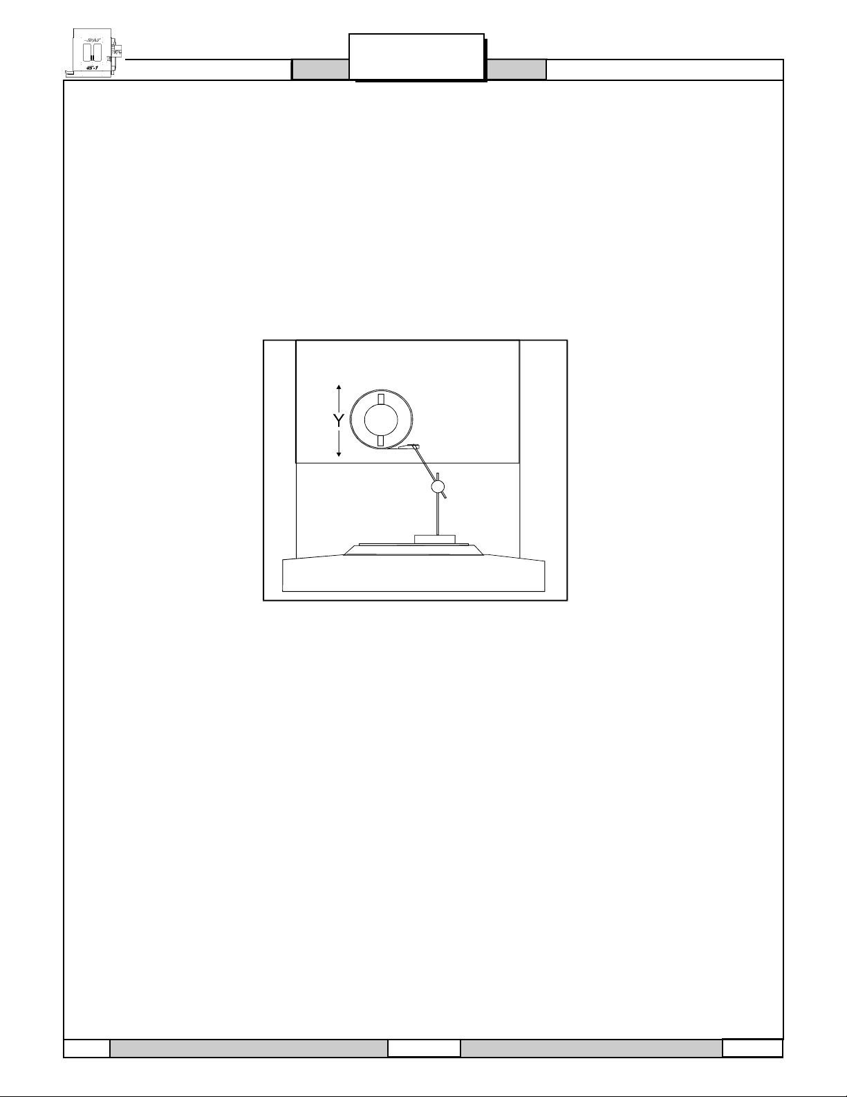
1. Set up a dial indicator and base on the mill table as shown in Fig. 3-2.
Fig. 3-2 Dial indicator in position to check Y-axis.
2. Set dial indicator and the Distance to go display in the HANDLE JOG mode to zero as follows:
- Zero the dial indicator.
- Press the MDI button on the control panel.
- Press the HANDLE JOG button on the
control panel. The Distance to go display
on the lower right hand corner should read:
X=0 Y=0 Z=0
3. Set the rate of travel to .001 on the control panel and jog the machine .010 in the positive (+) Y direction.
Jog back to zero (0) on the display. The dial indicator should read zero (0) ± .0001.
4. Repeat step three in the negative (-) direction.
TOTAL DEVIATION BETWEEN THE DIAL INDICATOR AND THE CONTROL PANEL DISPLAY SHOULD NOT
EXCEED .0002.
An alternate method used in checking backlash is to manually push up and down on the spindle head while
listening for a clunk. Also, watch for any rapid change in the dial indicator. Either of these indicate possible
backlash.
NOTE: The servos must be on to check backlash by this method.
12
96-9010 10-25-94
Page 14
HORIZONTAL
SERVO MOTORS / LEAD SCREWS
SERVICE MANUAL
TROUBLESHOOTING
CHECKING Z-AXIS:
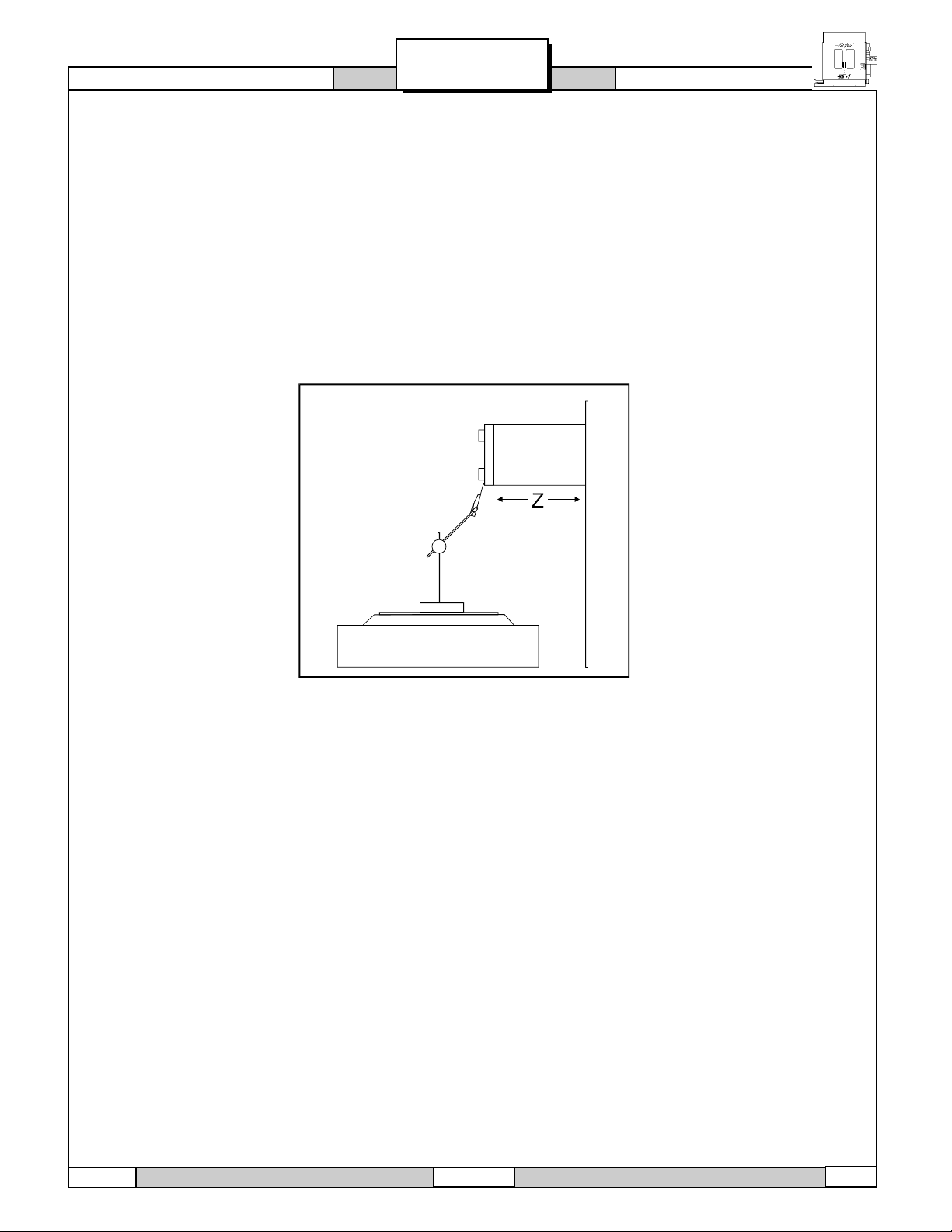
1. Set up a dial indicator and base on the table as shown in Fig. 3-3.
2. An alternate method for checking backlash is to manually push the column to the left/right and push the
spindle head up/down.
NOTE: Servos must be on to check for backlash in the Z-axis.
NOTE: Do not mistake deflection for backlash in the system.
Fig. 3-3 Dial indicator in position to check Z-axis.
> If backlash is found in the system,check for the following possible causes:
l Loose SHCS attaching the ball nut to the nut housing.
l Loose SHCS attaching the nut housing to the mill table, spindle head, or saddle,
depending on the axis.
l Loose clamp nut on the bearing sleeve. Tighten the SHCS on the clamp nut.
l Loose motor coupling.
l Broken or loose flex plates on the motor coupling.
NOTE: The coupling cannot be serviced in the field and must be replaced as a unit if it is found to be
defective.
l Loose SHCS attaching the bearing sleeve to the motor housing.
l Defective thrust bearings in the bearing sleeve.
l Loose SHCS attaching the axis motor to the motor housing. If the SHCS are found to be loose, inspect
the motor for damage.
l Incorrect backlash compensation number in the parameter in the machine. Check Parameters 13, 27,
and 41.
l Worn lead screw.
10-25-94 96-9010
13
Page 15

HORIZONTAL
TROUBLESHOOTING
SERVICE MANUAL
SERVO MOTORS / LEAD SCREWS
3.5 VIBRATION
´ EXCESSIVE SERVO MOTOR VIBRATION.
l If no A axis is present, swap the suspected bad servo motor with the A driver and check to see if
there is a driver problem.
l Check all Parameters of the suspected axis against the Parameters as shipped with the machine. If
there are any differences, correct those and determine how the Parameters were
changed. PARAMETER LOCK should normally be ON.
l A bad motor can cause vibration if there is an open or short in the motor. A short would normally cause
a GROUND FAULT or OVERCURRENT alarm; check the ALARMS. An ohmmeter applied to the motor
leads should show between 1 and 3 ohms between leads, and over 1 megohm from leads to ground.
If the motor is open or shorted, replacement it.
´ SERVO MOTOR OVERHEATING.
l If a motor OVERHEAT alarm occurs (ALARMS 135-138), check the Parameters for an incorrect setting.
Axis flags in Parameters 1, 15, or 29 can invert the overheat switch (OVER TEMP NC).
l If the motor is actually getting hot to the touch, there is excessive load on the motor. Check the users
application for excessive load or high duty cycle.
Check the lead screw for binding.
3.6 FOLLOWING ERROR
´ FOLLOWING ERROR ALARMS OCCUR ON ONE OR MORE AXES SPORADICALLY.
l Check DC bus voltage on diagnostics page #2. If it is at the low side of the recommended voltages,
change the transformer tap to the next lower voltage group as explained in the INSTALLATION MANUAL
l Check motor wiring
l Driver card replacement.
l Servo motor replacement.
4. TOOL CHANGER
4.1 DEFLECTION
Deflection is usually caused by ATC misalignment, and sometimes caused by damaged or poor quality
tooling, damaged spindle taper, or a damaged drawbar. Before beginning any troubleshooting, observe the
direction of the ATC deflection.
´ DURING A TOOL CHANGE, ATC APPEARS TO BE PUSHED OUT.
l Check to see if pull studs on the tool holder are correct and tight.
l Check the mechanical adjustment of the Y offset
14
96-9010 10-25-94
Page 16

HORIZONTAL
TOOL CHANGER
l Check Parameters 71, 72, and 143 against the values that are in the documentation sent with the
machine.
l Ensure the tool holders are held firmly in place by the extractor forks.
l Ensure the balls on the drawbar move freely in the holes in the drawbar when the tool release button is
pressed If they do not move freely, the ATC will be pushed out about ¼ before the tool holder is
seated in the taper, resulting in damage to the roller bolts on the ATC shuttle.
SERVICE MANUAL
TROUBLESHOOTING
´TOOL HOLDER STICKING IN THE SPINDLE TAPER CAUSES THE ATC TO BE PULLED IN AS
THE SPINDLE HEAD IS TRAVELING UP AFTER DEPOSITING THE TOOL HOLDER IN THE
CAROUSEL; ACCOMPANIED BY A POPPING NOISE AS THE TOOL HOLDER POPS OUT OF
THE SPINDLE TAPER.
NOTE: This problem may occur after loading a cold tool into a hot spindle (a result of thermal
expansion of the tool holder inside the spindle taper), or after heavy milling. If sticking occurs only during
these circumstances, no service is necessary.
l Check the condition of the customers tooling, verifying the taper on the tool holders ground and not
turnedLook for damage to the taper caused by chips in the taper or rough handling. If the tooling is
suspected, try to duplicate the symptoms with different tooling.
l Check the condition of the spindle taper. Look for damage caused by chips or damaged tooling. Also,
look for damage such as deep gouges in the spindle taper caused by tool crashing.
l Duplicate the cutting conditions under which the deflection occurs, but do not execute an automatic tool
change. Try instead to release the tool using the tool release button on the front of the spindle head. If
sticking is observed, the deflection is not caused by improper ATC adjustment, but is a problem in the
spindle head on the machine.
´ DURING A TOOL CHANGE, ATC APPEARS TO BE PULLED IN ; NO POPPING NOISES.
l Check the mechanical adjustment of the Y offset .
NOTE: If the adjustment is incorrect, a tool changer crash has occurred, and a thorough inspection of
the ATC is necessary at this time.
l Ensure the balls on the drawbar move freely in the holes in the drawbar when the tool release button is
pressed. If they do not move freely, the ATC will be pushed out about ¼ before the tool holder is
seated in the taper.
´ TOOL HOLDERS TWIST AGAINST EXTRACTOR FORK DURING A TOOL CHANGE.
l Check the alignment of the ATC in the X and Z axes.
l Check rotational alignment.
´ TOOL HOLDERS SPIN AT ALL POCKETS OF THE ATC
l ATC rotationally misaligned
Check the carousel offset (parameter 215)
NOTE: Observe the direction the tool holder rotates, as this will be the direction in which the X axis of
the ATC needs to be moved.
10-25-94 96-9010
15
Page 17

HORIZONTAL
TROUBLESHOOTING
4.2 CRASHING
Crashing of the ATC is usually a result of operator error. The most common ATC crashes are outlined as
follows:
SERVICE MANUAL
TOOL CHANGER
´ATC PROPERLY DEPOSITS A TOOL HOLDER IN THE SPINDLE, BUT THE TOOLS ARE DROPPED
ONTO THE MACHINE TABLE.
l Inspect the balls and the Belleville springs in the drawbar.
´ THE PART OR FIXTURE ON THE MILL TABLE CRASHES INTO LONG TOOLING OR INTO THE
ATC ITSELF DURING A TOOL CHANGE.
l Check for damage to the trap door on the ATC cover.
l Check for missing plastic riders on the ATC shutter.
´ ATC OUT OF ORIENTATION WITH THE SPINDLE.
Incorrect spindle orientation will cause the ATC to crash as the shuttle moves. Alarm 113 generated.
l Check the orientation of the machine.
´ATC WILL NOT RUN
l In all cases where the tool changer will not run, an alarm is generated to indicate either a shuttle in/out
problem or a turret rotation problem. These alarms will occur either on an attempt to change tools (ATC
FWD) or ZERO RETURN the machine (AUTO ALL AXES).
´ TURRET WILL NOT ROTATE; TURRET MOTOR IS NOT GETTING POWER (COMMAND A TOOL
CHANGE AND FEEL FOR POWER BEING APPLIED TO THE TURRET MOTOR).
l Check that the TC CW/ TC CCW LED on the I/O PCB is illuminated when a toolchange takes place.
´ ATC PROPERLY DEPOSITS A TOOL HOLDER IN THE SPINDLE BUT GIVES A SHUTTLE OUT
FAULT.
l Check the shuttle in/out switch adjustment.
16
96-9010 10-25-94
Page 18

HORIZONTAL
SERVICE MANUAL
TROUBLESHOOTING
10-25-94 96-9010
17
Page 19

HORIZONTAL
ALARMS: 102-114
SERVICE MANUAL
ALARMS
ALARMS
Any time an alarm is present, the lower right hand corner will have a blinking ALARM. Push the ALARM
display key to view the current alarm. All alarms are displayed with a reference number and a complete
description. If the RESET key is pressed, one alarm will be removed from the list of alarms. If there are
more than 18 alarms, only the last 18 will be displayed and the CURSOR DOWN key must be used to see
the rest. The presence of any alarm will prevent the operator from starting a program.
Note that the tool changer alarms can be easily corrected by first correcting any mechanical problem,
pressing RESET until the alarms are clear, selecting ZERO RET mode, and selecting AUTO ALL AXES.
Some messages are displayed while editing to tell the operator what is wrong, but these are not alarms.
The following list shows the alarm number and the cause of the alarm. Please refer to this list before
resuming normal operation when an alarm occurs.
102 SERVOS OFF
This is not an alarm; but indicates that the servo motors are off, the tool changer is disabled, the coolant
pump is off, and the spindle motor is stopped. Caused by EMERGENCY STOP, motor faults, tool changer
problems, or power fail.; check for other causes.
103 X FOLLOWING ERROR TOO LARGE
104 Y FOLLOWING ERROR TOO LARGE
105 Z FOLLOWING ERROR TOO LARGE
106 A FOLLOWING ERROR TOO LARGE
These alarms can be caused by power problems, motor problems, driver problems, the slide being run into
the mechanical stops, or excessive axis load. The difference between the motor position and the commanded position has exceeded a parameter. The motor may also be stalled, disconnected, or the driver
failed. The servos will be turned off and a RESET must be done to restart.
107 EMERGENCY OFF
EMERGENCY STOP button was pressed. Servos are also turned off. After the E-STOP is released, the
RESET button must be pressed at least twice to correct this; once to clear the E-STOP alarm and once to
clear the Servo Off alarm. This is an operator-initiated condition. If you do not know why it occurred, check
wiring to emergency stop circuit.
108 X SERVO OVERLOAD
109 Y SERVO OVERLOAD
110 Z SERVO OVERLOAD
111 A SERVO OVERLOAD
Excessive load on X-axis motor. This can occur if the load on the motor over a period of several seconds or
even minutes is large enough to exceed the continuous rating of the motor. The servos will be turned off
when this occurs. This can be caused by running into the mechanical stops but not much past them. It can
also be caused by anything that causes a very high load on the motors.
Servo, servo driver and ball screw.
112 NO INTERRUPT
This alarm can be caused by electrical interference or an electronics problem.
113 SHUTTLE IN FAULT
114 SHUTTLE OUT FAULT
18
96-9010 10-25-94
Page 20

HORIZONTAL
ALARMS
Tool changer not completely to right or left. During a tool changer operation the tool in/out shuttle failed to get to
the in or out position. Parameters 62 and 63 can adjust the time-out times. This alarm can be caused by
anything that jams the motion of the slide or by the presence of a tool in the pocket facing the spindle. A loss of
power to the tool changer can also cause this, so check fuse FU5 and relays 1-8, 2-1, and 2-2.
Tool changer operation.
115 TURRET ROTATE FAULT
Tool carousel motor not in position. During a tool changer operation the tool turret failed to start moving or failed
to stop at the right position. Parameters 60 and 61 can adjust the time-out times. This alarm can be caused by
anything that jams the rotation of the turret. A loss of power to the tool changer can also cause this, so check
fuse FU5 and relays 1-8, 2-3, and Turret operation.
116 SPINDLE ORIENTATION FAULT
Spindle did not orient correctly. During a spindle orientation function, the spindle is rotated until the lock pin
drops in; but the lock pin never dropped. Parameters 66, 70, 73, and 74 can adjust the time-out times. This can
be caused by a trip of circuit breaker CB4, a lack of air pressure, or too much friction with the orientation pin.
119 OVER VOLTAGE
Incoming line voltage is above maximum (about 255V when wired for 240 or 235 when wired for 208). The
servos will be turned off and the spindle, tool changer, and coolant pump will stop. If this condition remains for
4.5 minutes, an automatic shutdown will begin. This can also be caused by an electronic problem.
Line voltage adjustment taps.
SERVICE MANUAL
ALARMS: 115-123
120 LOW AIR PRESSURE
Air pressure dropped below 80 PSI for a period defined by Parameter 76. Check your incoming air pressure for
at least 100 PSI and ensure the regulator is set at 85 PSI. If this is not caused by low air pressure, check
pressure sensor at spindle head and wiring back to IOPCB. Check Parameter 76, which is used to delay the
low air alarm condition for short outages. Air blast during tool change can cause your air supply to drop
pressure; monitor the pressure drop during a tool unclamp.
121 LOW LUB OR LOW PRESSURE
Way lube is low or empty or there is no lube pressure or too high a pressure. Check tank at rear of mill and
below control cabinet. Also check connector P5 on the side of the control cabinet. Check that the lube lines are
not blocked. This can be caused by failure of the pump to provide pressure, failure of the lube pressure sensor,
a wiring error, or a parameter error. See Air and Oil Line Diagrams to check level switch and pressure switch
(cable 960).
122 CONTROL OVER HEAT
The control internal temperature is above 150° F. This can be caused by almost anything in the control overheating. But is usually caused by overheat of the two regen resistors for servos and spindle drive. This alarm
will also turn off the servos, spindle drive, coolant pump, and tool changer. One common cause of this overheat
condition is an input line voltage too high. If this condition remains for 4.5 minutes, an automatic shutdown will
begin. It is also caused by incorrect transformer tapping, SDIST PCB problem, or Spindle Drive problem.
123 SPINDLE DRIVE FAULT
Overheat or failure of spindle drive or motor. The exact cause is indicated in the LED window of the spindle
drive inside the control cabinet. This can be caused by a stalled motor, shorted motor, overvoltage,
undervoltage, overcurrent, overheat of motor, or drive failure. e. Front of drive indicates type of problem. If not
a Drive problem, check wiring to IOPCB (cable 780).
10-25-94 96-9010
19
Page 21

HORIZONTAL
ALARMS: 124-138
124 LOW BATTERY
Memory batteries need replacing within 30 days. This alarm is only generated at POWER ON and indicates
that the 3.3V Lithium battery is below 2.5V. If this is not corrected within about 30 days, stored programs,
parameters, offsets, and settings may be lost.
Replacement of Microprocessor PCB or battery.
129 M FIN FAULT
This indicates an external M-code wiring error was detected at power-on. Check your wiring to the M-FIN
signal.
130 TOOL UNCLAMPED
131 TOOL NOT CLAMPED
Tool release piston is energized at power up, or, tool release piston is not Home. This is a possible fault in
the air solenoids, relays on the IO Assembly, the draw bar assembly, or wiring.
Tool clamp/unclamp problems.
132 POWER DOWN FAILURE
The control attempted to shut-off and could not. The auto-off relay on the IOPCB did not open the main
contactor circuit. Check the wiring from IOPCB to POWER PCB.
IOPCB replacement. ELECTRICAL
SERVICE MANUAL
ALARMS
133 SPINDLE LOCKED
Shot pin did not release. This is detected when spindle motion is commanded. Check the solenoid that
controls the air to the lock, relay 2-8, the wiring to the sense switch, and the switch.
Check for correct function of the shot pin.
134 TOOL CLAMP FAULT
Tool did not release from spindle when commanded. Check air pressure and solenoid circuit breaker CB4.
Can also be caused by misadjustment of draw bar assembly.
Tool clamp/unclamp problems.
135 X MOTOR OVER HEAT
136 Y MOTOR OVER HEAT
137 Z MOTOR OVER HEAT
138 A MOTOR OVER HEAT
Servo motor overheat. The temperature sensor in the motor indicates over 1500F. This can be caused by an
extended overload of the motor such as leaving the slide at the stops for several minutes.
Check of servo motors and ball screws.
A parameter or a wiring error can also cause this alarm.
20
96-9010 10-25-94
Page 22

HORIZONTAL
ALARMS
139 X MOTOR Z FAULT
140 Y MOTOR Z FAULT
141 Z MOTOR Z FAULT
142 A MOTOR Z FAULT
Encoder marker pulse count failure. This alarm usually indicates that the encoder has been damaged and
encoder position data is unreliable. This can also be caused by loose connectors at P1-P4.
Check motor/encoder and wiring.
It can also be caused by the MOTIF PCB.
143 SPINDLE NOT LOCKED
Shot pin not fully engaged when a tool change operation is being performed. Check air pressure and
solenoid circuit breaker CB4. This can also be caused by a fault in the sense switch that detects the
position of the lock pin.
144 TIMEOUT - CALL YOUR DEALER
Time allocated for use prior to payment exceeded.
Not a mechanical or electrical problem.
145 X LIMIT SWITCH
146 Y LIMIT SWITCH
147 Z LIMIT SWITCH
148 A LIMIT SWITCH
Axis hit limit switch or switch disconnected. This is not normally possible as the stored stroke limits will
stop the slides before they hit the limit switches. Check the wiring to the limit switches and connector P5 at
the side of the main cabinet. Can also be caused by a loose encoder shaft at the back of the motor or
coupling of motor to the screw.
SERVICE MANUAL
ALARMS: 139-156
149 SPINDLE TURNING
Spindle not at zero speed for tool change. A signal from the spindle drive indicating that the spindle drive
is stopped is not present while a tool change operation is going on.
150 Z AND TOOL INTERLOCKED
Tool changer not at home and Z is neither at machine home or above tool. If RESET, E-STOP, or POWER
OFF occurs during tool change, Z-axis motion and tool changer motion may not be safe. Check the position
of the tool changer and remove the tool if possible. Re-initialize with the AUTO ALL AXES button but be sure
that the pocket facing the spindle afterwards does not contain a tool. Indicates a dangerous condition with
the position of the Z axis and the tool changer. It is usually preceded by an alarm related to the tool
changer.
Tool changer problems.
152 SELF TEST FAIL
This can be caused by an electronics problem or electrical interference. All motors and solenoids are shut
down. This is most likely caused by a fault of the processor board stack at the top left of the control. Call
your dealer.
153 X AXIS Z CH MISSING
154 Y AXIS Z CH MISSING
155 Z AXIS Z CH MISSING
156 A AXIS Z CH MISSING
These alarms indicate a problem with the servo axis encoder. All servos are turned off. It can also be
caused by wiring errors, electronics problems, encoder contamination, parameter errors, or by loose
connectors at P1-P4..
10-25-94 96-9010
21
Page 23

HORIZONTAL
ALARMS: 157-169
157 MOTOR INTERFACE PCB FAILURE
Internal circuit board problem. The MOTIF PCB in the processor stack is tested at POWER ON.
158 VIDEO/KEYBOARD PCB FAILURE
Internal circuit board problem. The VIDEO PCB in the processor stack is tested at POWER ON. This could
also be caused by a short in the front panel membrane keypad.
159 KEYBOARD FAILURE
Keyboard shorted or button pressed at POWER ON. A POWER ON test of the membrane keypad has found
a shorted button. It can also be caused by a short in the cable from the main cabinet or by holding a switch
down during POWER ON.
This can also be caused by a bad cable 700.
Be sure the problem is not in the cable before replacing keypad.
160 LOW VOLTAGE
This can be caused by a line voltage problem, a transformer tap problem, or an electronic problem. Cable
980 can cause this problem.
161 X AXIS OVER CURRENT OR DRIVE FAULT
162 Y AXIS OVER CURRENT OR DRIVE FAULT
163 Z AXIS OVER CURRENT OR DRIVE FAULT
164 A AXIS OVER CURRENT OR DRIVE FAULT
These alarms indicate a problem with servo motor, the servo drive, or excessive load on servos. Possibly
caused by a stalled or overloaded motor. The servos are turned off. This can be caused by running a short
distance into a mechanical stop. It can also be caused by a short in the motor or a short of one motor lead
to ground.
Check of servo motor and ball screw.
SERVICE MANUAL
ALARMS
165 X ZERO RET MARGIN TOO SMALL
166 Y ZERO RET MARGIN TOO SMALL
167 Z ZERO RET MARGIN TOO SMALL
168 A ZERO RET MARGIN TOO SMALL
This alarm indicates a problem with limit switches, parameters, or motor encoders for servos, and this
alarm will occur if the home/limit switches move or are misadjusted. This alarm also indicates that the zero
return position may not be consistent from one zero return to the next. The encoder Z channel signal must
occur between 1/8 and 7/8 revolution of where the home switch releases. This will not turn the servos off
but will stop the zero return operation.
If a new motor or encoder is installed, this alarm is likely before grid offset parameters are adjusted.
169 SPINDLE DIRECTION FAULT
The spindle started turning in the wrong direction. This alarm occurs only for rigid tapping. It can be
caused by a bad rigid tapping encoder, a wiring error, or a parameter error.
Installation of rigid tapping encoder.
22
96-9010 10-25-94
Page 24

HORIZONTAL
ALARMS
SERVICE MANUAL
170 PHASE LOSS L1-L2
171 PHASE LOSS L2-L3
172 PHASE LOSS L3-L1
These alarms indicate a problem with incoming line voltage. This usually indicates that there was a transient
loss of input power to the machine.
Checking line voltage.
173 SPINDLE REF SIGNAL MISSING
The Z channel pulse from the spindle encoder is missing for hard tapping synchronization. This alarm occurs
only for rigid tapping.
Check rigid tapping encoder.
174 TOOL LOAD EXCEEDED
The tool load monitor option is selected and the maximum load for a tool was exceeded in a feed. This alarm
can only occur if the tool load monitor function is installed in your machine. This is not normally a machine fault.
Check the setup.
175 GROUND FAULT DETECTED
A ground fault condition was detected in the 115V AC supply. This can be caused by a short to ground in any of
the servo motors, the tool change motors, the fans, or the oil pump. If the fault occurs repeatedly, remove
motors one at a time to isolate fault. If it occurs rarely, the motor in motion at the fault is the likely cause. A
short of the spindle head solenoid cables can also cause this condition.
ALARMS: 170-186
176 OVER HEAT SHUTDOWN
This alarm is actually caused by a previous Over Heat alarm. After 4 1/2 minutes of overheat, the control
begins an automatic shutdown.
177 OVER VOLTAGE SHUTDOWN
This alarm is actually caused by a previous Over Voltage alarm. After 4 1/2 minutes of overvoltage, the control
begins an automatic shutdown.
178 DIVIDE BY ZERO
Indicates an electronics or software problem.
If intermittent or not consistent:
180 TOOL ARM ROTATION FAULT
181 TOOL POT POSITION FAULT
These alarms are not Implemented.
182 X CABLE FAULT
183 Y CABLE FAULT
184 Z CABLE FAULT
185 A CABLE FAULT
Cable from axis encoder does not have valid differential signals. See Section 10, Mechanical Service, for
replacement of motor, encoder, and cabling. This can also be caused by a MOTIF PCB problem.
186 SPINDLE NOT TURNING
Status from spindle drive indicates that it is not turning when it is expected.
10-25-94 96-9010
23
Page 25

HORIZONTAL
ALARMS: 201-243
201 PARAMETER CRC ERROR
Parameters lost maybe by low battery. Check for a low battery and low battery alarm.
202 SETTING CRC ERROR
Settings lost maybe by low battery. Check for a low battery and low battery alarm.
203 LEAD SCREW CRC ERROR
Lead screw compensation tables lost maybe by low battery. Check for CRC Error low battery and low battery
alarm.
204 OFFSET CRC ERROR
Offsets lost maybe by low battery. Check for a low battery and low battery alarm.
205 PROGRAMS CRC ERROR
Users program lost maybe by low battery. Check for a low battery and low battery alarm.
206 INTERNAL PROG ERROR
Software Error.
207 QUEUE ADVANCE ERROR
Software Error.
SERVICE MANUAL
ALARMS
208 QUEUE ALLOCATION ERROR
Software Error.
209 QUEUE CUTTER COMP ERROR
Software Error.
210 INSUFFICIENT MEMORY
Not enough memory to store users program. Check the space available in the LIST PROG mode and possibly
delete some programs.
211 ODD PROG BLOCK
Software Error.
212 PROG INTEGRITY ERROR
Software Error.
213 EPROM CRC ERROR
All of these alarms indicate a software or electronics problem.
Replace Microprocessor PCB.
240 EMPTY PROG OR NO EOB
Software Error.
241 INVALID CODE
RS-232 load bad. Data was stored as comment (RS-232 communications problem or RS-232 program format
problem). Check the program being received. See the Programming and Operation Manual.
242 NO END
Software Error.
243 BAD NUMBER
Data entered is not a number.
24
96-9010 10-25-94
Page 26

HORIZONTAL
ALARMS
SERVICE MANUAL
244 MISSING )
Comment must end with a ) .
245 UNKNOWN CODE
Check input line or data from RS-232. This alarm can occur while editing data into a program or loading
from RS-232.
246 STRING TOO LONG
These alarms usually indicate an operator illegal action., such as input line too long. The data entry line
must be shortened. See the Programming and Operation Manual.
247 CURSOR DATA BASE ERROR
Software Error.
248 NUMBER RANGE ERROR
Number entry is out of range.
249 PROG DATA BEGINS ODD
250 PROG DATA ERROR
251 PROG DATA STRUCT ERROR
252 MEMORY OVERFLOW
253 PROG DATA ERROR
254 PROG DATA ERROR
255 PROG DATA ERROR
256 PROG DATA ERROR
257 PROG DATA ERROR
ALARMS: 244-306
All of these alarms indicate and RS-232 communication problem or a software or electronics problem. See
Programming and Operation Manual for RS-232 operation.
258 INVALID DPRNT FORMAT
This alarm is caused by an error in the way the programmer uses the macro DPRNT function. See the
Programming and Operation Manual.
302 - 390
All of the 302 through 390 alarms are caused by programming problems in the users NC program. See the
Programming and Operation Manual.
302INVALID R IN G02 OR G03
Check your geometry with the Help page. R must be less than or equal to half the distance from start to
end within an accuracy of 0.0010 inches.
303INVALID X, Y, OR Z IN G02 OR G03
Check your geometry with the Help page.
304INVALID I, J, OR K IN G02 OR G03
Check your geometry with the Help page. Radius at start must match radius at end of arc within 0.0010
inches.
305INVALID Q IN CANNED CYCLE
Q in a canned cycle must be greater than zero.
306INVALID I, J, OR K IN CANNED CYCLE
I, J, and K in a canned cycle must be greater than zero.
10-25-94 96-9010
25
Page 27

HORIZONTAL
ALARMS: 307-327
307SUBPROGRAM CALL NESTING TOO DEEP
Subprogram nesting is limited to nine levels. Simplify your program.
308CANNED CYCLE NESTING TOO DEEP
Software Error.
309MAX FEED RATE EXCEEDED
Use a lower feed rate.
310INVALID G CODE
G code not defined and is not a macro call.
311 UNKNOWN CODE
Possible corruption of memory by low battery. Call your dealer.
312PROGRAM END
End of subroutine reached before M99. Need an M99 to return from subroutine.
313NO P CODE IN M98
Must put subprogram number in P code.
SERVICE MANUAL
ALARMS
314SUBPROGRAM OR MACRO NOT IN MEMORY
Check that a subroutine is in memory or that a macro is defined.
315INVALID P CODE IN M97, M98 OR M99
The P code must be the name of a program stored in memory without a decimal point for M98 and must be
a valid N number for M99.
316X OVER TRAVEL RANGE
317Y OVER TRAVEL RANGE
318Z OVER TRAVEL RANGE
319A OVER TRAVEL RANGE
Axis will exceed stored stroke limits. This is a parameter in negative direction and is machine zero in the
positive direction. This will only occur during the operation of a users program.
320NO FEED RATE SPECIFIED
Must have a valid F code for interpolation functions.
321 AUTO OFF
A fault turned off the servos automatically; occurs in debug mode only.
324INVALID P CODE IN G04
P code in G04 is over 1000.0 or over 9999.
325QUEUE FULL
Control problem; call your dealer.
326G04 WITHOUT P CODE
Put a Pn.n for seconds or a Pn for milliseconds.
327NO LOOPING FOR M CODE EXCEPT M97, M98
L code not used here. Remove L Code.
26
96-9010 10-25-94
Page 28

HORIZONTAL
ALARMS
328INVALID TOOL NUMBER
Tool number must be between 1 and 24.
329UNDEFINED M CODE
That M code is not defined and is not a macro call.
330UNDEFINED MACRO CALL
Macro name O90nn not in memory. A macro call definition is in parameters and was accessed by user program but that macro was not loaded into memory.
331RANGE ERROR
Number too large.
332H AND T CODES NOT MATCHED
This alarm is generated when Setting 15 is turned ON and an H code number in a running program does not
match the tool number in the spindle. Correct the Hn codes, select the right tool, or turn off Setting 15.
333X-AXIS DISABLED
334Y-AXIS DISABLED
335Z-AXIS DISABLED
Parameters have disabled this axis. Not normally possible in VMC.
SERVICE MANUAL
ALARMS: 328-348
336A-AXIS DISABLED
Parameters have disabled this axis. Must enable A-axis to program it or remove programming of A-axis. The Aaxis can be disabled permanently by Parameter 43 or temporarily by Setting 30.
338INVALID IJK AND XYZ IN G02 OR G03
There is a problem with circle definition; check your geometry.
339MULTIPLE CODE
Only one M, X, Y, Z, A, Q, etc. allowed in any block or two G codes in the same group.
340CUTTER COMP BEGINS WITH G02 OR G03
Select cutter comp earlier.
341CUTTER COMP ENDS WITH G02 OR G03
Disable cutter comp later.
342CUTTER COMP PATH TOO SMALL
Geometry not possible. Check your geometry with the Help page.
344CUTTER COMP WITH G18 OR G19
Cutter comp only allowed in XY plane (G17).
345SCALING PARAMETERS WONT ALLOW G17 PLANE
Parameters 5 and 19 must be same value.
346SCALING PARAMETERS WONT ALLOW G18 PLANE
Parameters 5 and 33 must be same value.
347SCALING PARAMETERS WONT ALLOW G19 PLANE
Parameters 19 and 33 must be same value.
348ILLEGAL SPIRAL MOTION
Linear axis path is too long. For helical motions, the linear path must not be more than the length of the circular
component.
10-25-94 96-9010
27
Page 29

HORIZONTAL
ALARMS: 349-366
349PROG STOPPED WITHOUT CANCEL OF CUTTER COMP
Information message only. Fix or Ignore.
350CUTTER COMP LOOK AHEAD TOO SMALL
There are too many non-movement blocks between motions when cutter comp is being used. Remove some
intervening blocks.
352AUX AXIS POWER OFF
Aux B, C, U, V, or W axis indicate servo off. Check auxiliary axes. Status from control was OFF.
353AUX AXIS NO HOME YET
A ZERO RET has not been done yet on the aux axes. Check auxiliary axes. Status from control was LOSS.
354AUX AXIS NOT CONNECTED
Aux axes not responding. Check auxiliary axes and RS-232 connections.
355AUX AXIS POSITION LOST
Mismatch between VMC and aux axes position. Check aux axes and interfaces. Make sure no manual inputs
occur to aux axes.
356AUX AXIS TRAVEL LIMIT
Aux axes are attempting to travel past their limits.
SERVICE MANUAL
ALARMS
357AUX AXIS DISABLED
Aux axes are disabled.
358MULTIPLE AUX AXIS
Can only move one auxiliary axis at a time.
359INVALID I, J, OR K IN G12 OR G13 CIRC POCKET MILLING
Check your geometry with the Help page.
360TOOL CHANGER DISABLED BY PARAMETERS
Check Parameter 57. Not a normal condition for VMC.
361GEAR CHANGE DISABLED BY PARAMETERS
Check Parameter 57. Not a normal condition for VMC.
362TOOL USAGE ALARM
Tool life limit was reached. To continue, reset the usage count in the Current Commands display and press
RESET.
363COOLANT LOCKED
Override is off and program tried to turn on coolant.
364NO CIRCULAR INTERP ALLOWED ON AUX AXIS
Only rapid or feed is allowed with aux axes.
365CUTTER COMP INTERFERENCE
G02 or G03 cut cannot be done with tool size.
366CUTTER COMP INTERFERENCE
Tool doesnt fit inside of cut.
28
96-9010 10-25-94
Page 30

HORIZONTAL
ALARMS
SERVICE MANUAL
367CUTTER COMP INTERFERENCE
G01 cannot be done with tool size.
368 GROOVE TOO SMALL
Tool too big to enter cut.
369TOOL TOO BIG FOR CUTTER COMP
Use a smaller tool for cut.
370POCKET DEFINITION ERROR
Check geometry for G150.
371INVALID I, J, K, OR Q
Check G150.
372TOOL CHANGE IN CANNED CYCLE
Tool change not allowed while canned cycle is active.
373INVALID CODE IN DNC
A code found in a DNC program could not be interpreted because of restrictions to DNC.
374MISSING XYZA IN G31 OR G36
G31 skip function requires an X, Y, Z, or A move.
ALARMS: 367-385
375MISSING Z OR H IN G37
G37 auto offset skip function requires H code, Z value, and tool offset enabled. X, Y, and A values not allowed.
376NO CUTTER COMP IN SKIP
Skip G31 and G37 functions cannot be used with cutter compensation.
377NO SKIP IN GRAPH/SIM
Graphics mode cannot simulate skip function.
378SKIP SIGNAL FOUND
Skip signal check code was included but skip was found when it was not expected.
379SKIP SIGNAL NOT FOUND
Skip signal check code was included but skip was not found when it was expected.
380X, Y, A, OR G49 NOT ALLOWED IN G37
G37 may only specify Z-axis and must have tool offset defined.
381G43 OR G44 NOT ALLOWED IN G36
Auto work offset probing must be done without tool offset.
382D CODE REQUIRED IN G35
A Dnn code is required in G35 in order to store the measured tool diameter.
383INCHES IS NOT SELECTED
G20 was specified but settings have selected metric input.
384METRIC IS NOT SELECTED
G21 was specified but settings have selected inches.
385INVALID L, P, OR R CODE IN G10
G10 was used to changes offsets but L, P, or R code is missing or invalid.
10-25-94 96-9010
29
Page 31

HORIZONTAL
ALARMS: 403-416
403 - 420
All of the 403 through 420 alarms are caused by communications problems with RS-232. See the Programming
and Operation Manual.
403RS-232 DIRECTORY FULL
Cannot have more than 100 programs in memory.
404RS-232 NO PROGRAM NAME
Need name in programs when receiving ALL; otherwise has no way to store them.
405RS-232 ILLEGAL PROGRAM NAME
Check files being loaded. Program name must be Onnnn and must be at beginning of a block.
406RS-232 MISSING CODE
A receive found bad data. Check your program. The program will be stored but the bad data is turned into a
comment.
407RS-232 INVALID CODE
Check your program. The program will be stored but the bad data is turned into a comment.
408RS-232 NUMBER RANGE ERROR
Check your program. The program will be stored but the bad data is turned into a comment.
SERVICE MANUAL
ALARMS
409RS-232 INVALID N CODE
Bad Parameter or Setting data. User was loading settings or parameters and something was wrong with the
data.
410RS-232 INVALID V CODE
Bad Parameter or Setting data. User was loading settings or parameters and something was wrong with the
data.
411 RS-232 EMPTY PROGRAM
Check your program. Between % and % there was no program found.
412RS-232 UNEXPECTED END OF FILE
Check Your Program. An ASCII EOF code was found in the input data before program receive was complete.
This is a decimal code 26.
413RS-232 INSUFFICIENT MEMORY
Program received doesnt fit. Check the space available in the LIST PROG mode and possibly delete some
programs.
414RS-232 BUFFER OVERFLOW
Data sent too fast to CNC. This alarm is not normally possible as this control can keep up with even 38400 bits
per second.
415RS-232 OVERRUN
Data sent too fast to CNC. This alarm is not normally possible as this control can keep up with as much as
38400 bits per second.
416RS-232 PARITY ERROR
Data received by CNC has bad parity. Check parity settings, number of data bits and speed. Also check your
wiring.
30
96-9010 10-25-94
Page 32

HORIZONTAL
ALARMS
SERVICE MANUAL
417 RS-232 FRAMING ERROR
Data received was garbled and proper framing bits were not found. One or more characters of the data will
be lost. Check parity settings, number of data bits and speed.
418 RS-232 BREAK
Break condition while receiving. The sending device set the line to a break condition. This might also be
caused by a simple break in the cable.
419INVALID FUNCTION FOR DNC
A code found on input of a DNC program could not be interpreted.
501 - 538
All of the 501 through 538 alarms are caused by errors in macro programming. See the Programming and
Operation Manual.
ALARMS: 417-538
10-25-94 96-9010
31
Page 33

HORIZONTAL
DISCRETE INPUTS
SERVICE MANUAL
DIAGNOSTIC DATA
DIAGNOSTIC DATA
The ALARM MSGS display is the most important source of diagnostic data. At any time after the
machine completes its power-up sequence, it will either perform a requested function or stop with an alarm.
Refer to Section 2.5 for a complete list of alarms, their possible causes, and some corrective action.
If there is an electronics problem, the controller may not complete the power-up sequence and the CRT will
remain blank. In this case, there are two sources of diagnostic data; these are the audible beeper and the
LEDs on the processor PCB. If the audible beeper is alternating a ½ second beep, there is a problem with the
main control program stored in EPROMs on the processor PCB. If any of the processor electronics cannot be
accessed correctly, the LEDs on the processor PCB will light or not .
If the machine powers up but has a fault in one of its power supplies, it may not be possible to flag an
alarm condition. If this happens, all motors will be kept off and the top left corner of the CRT will have the
message:
POWER FAILURE ALARM and all other functions of the control will be locked out.
When the machine is operating normally, a second push of the PARAM/DGNOS key will select the diagnostics display page. The PAGE UP and PAGE DOWN keys are then used to select one of two different displays.
These are for diagnostic purposes only and the user will not normally need them. The diagnostic data consists
of 32 discrete input signals, 32 discrete output relays and several internal control signals. Each can have the
value of 0 or 1. In addition, there are up to three analog data displays and an optional spindle RPM display.
Their number and functions are listed in the section below.
DISCRETE INPUTS
# Name Description # Name Description
1 TC IN Tool Changer In 17 SPLO SpindleLocked
2 TC OUT Tool Changer Out 18 SP FLT Spindle Drive Fault
3 T ONE At Tool One 19 SP SP* Spindle Not Stopped
4 LO CNT Low Coolant 20 SP AT* Spindle Not At Speed
5 TC MRK T.C. Geneva Mark 21 LO OIL Spindle/GB coolant low
6 SP HIG Spindle In High 22 A161 Safety Interlock status
7 SP LOW Spindle In Low 23 spare
8 EM STP Emergency Stop 24 spare
9 DOOR S Door Open Switch 25 UNCLA* Remote tool unclamp
10 M-FIN* Not M Func Finish 26 LO PH A Low voltage in phase 1
11 OVERV* Not Over Voltage 27 LO PH B Low voltage in phase 2
12 LO AIR Low Air Pressure 28 LO PH C Low voltage in phase 3
13 LO LUB Low Lube Oil 29 GR FLT Ground fault
14 OVRHT* Not Over Heat 30 SKIP Skip Signal
15 DB OPN Tool Unclamped 31 spare
16 DB CLS Tool Clamped 32 spare
32
96-9010 10-25-94
Page 34

HORIZONTAL
DIAGNOSTIC DATA
SERVICE MANUAL
DISCRETE INPUTS
DISCRETE OUTPUTS
# Name Description # Name Description
1 SRV PO Servo Power On 17 M21 Spare M Functions
2 SP FOR Spindle Forward 18 M22
3 SP REV Spindle Reverse 19 K111 Spindle & T.C. Enable
4 SP RST Spindle Reset 20 K210 E-Stop Enable
5 4TH BK 4th Axis Brk Rel 21 UNCLPR Unclamp pre-charge
6 COOLNT Coolant Pump 22 M26
7 AUT OF Auto Turn Off 23 5TH BK 5th Axis Brake
8 SP FAN Spind Motor Fan 24 Y160 Door Lock
9 TC IN Tool Changer In 25 spare
10 TC OUT Tool Changer Out 26 spare
11 TC CW Tool Changer CW 27 spare
12 TC CCW Tool Changer CCW 28 spare
13 SP HIG Spindle High Gear 29 spare
14 SP LOW Spindle Low Gear 30 spare
15 T UNCL Tool Unclamped 31 spare
16 SP LOK Spindle Lock Cmd 32 spare
The 32 inputs are numbered the same as the 32 connections on the inputs printed circuit board. The last
eight outputs are reserved for expansion by HAAS.
The second page of diagnostic data is displayed using the PAGE UP and PAGE DOWN keys. It
contains:
Name Description Name Description
X Z CH X-axis Z Channel X ZIRQ X-axis Z channel interrupt
Y Z CHY Axis Z Channel Y ZIRQ Y-axis Z channel interrupt
Z Z CH Z-axis Z Channel Z ZIRQ Z-axis Z channel interrupt
A Z CH A-axis Z Channel A ZIRQ A-axis Z channel interrupt
X HOME X-axis Home/Lim Switch 1K IRQ 1 kHz Interrupt
Y HOME Y-axis Home Z IRQ Z channel interrupt
Z HOME Z-axis Home SPZIRQ Spindle encoder Z interrupt
A HOME A-axis Home SELF T Self-Test Input
X OVRH X Motor OverTemp X CABL Broken cable to X encoder
Y OVRH Y Motor OverTemp Y CABL Broken cable to Y encoder
Z OVRH Z Motor OverTemp Z CABL Broken cable to Z encoder
A OVRH A Motor OverTemp A CABL Broken cable to A encoder
OVC X X Drive Overcurrent spare
OVC Y Y Drive Overcurrent spare
OVC Z Z Drive Overcurrent spare
OVC A A Drive Overcurrent AD EOC A-to-D End of Conversion
INPUTS 2
10-25-94 96-9010
33
Page 35

ANALOG DATA
HORIZONTAL
SERVICE MANUAL
ANALOG DATA
Name Description
DC BUSS DC Servo Buss Voltage
SP TEMP Spindle temperature F
SP LOAD Spindle load in %
AUX TMP Not used
SP SPEED Spindle RPM CW or CCW
DIAGNOSTIC DATA
34
96-9010 10-25-94
Page 36

HORIZONTAL
SERVICE MANUAL
10-25-94 96-9010
35
Page 37

MECHANICAL SERVICE
HORIZONTAL
SERVICE MANUAL
36
96-9010 10-25-94
Page 38

TOOL RELEASE PISTON
MECHANICAL
SERVICE
1. TOOL RELEASE PISTON
HORIZONTAL
SERVICE MANUAL
MECHANICAL SERVICE
CAUTION! In order to keep the spindle crashing
down place a two-by-four between the air cylinder
bracket and the bottom of the column casting.
REMOVAL:
1. Power off the machine
2. Disconnect the main air supply at the air lube
panel.
3. Disconnect air lines at the tool unclamp solenoid
and precharge line.
4. Disconnect clamp/unclamp cables (quick disconnect and solenoid wiring located on the solenoid
bracket.
5. Remove the four 3/8-16 x 1 3/4" SHCS holding the
tool release piston assembly to the head casting.
3/8" AIR HOSE
FITTING
6. Remove entire tool release piston assembly.
INSTALLATION:
1. Ensure spindle, drawbar and drive belt have been
properly replaced .
2. Re-install the tool release piston assembly and
evenly tighten down the four 3/8-16 x 1 3/4" SHCS
until completely tightened.
3. Re-connect the airlines in reverse order as they
were removed and connect all solenoid and switch
wiring.
4. Shim TRP Assembly.
5. Verify tool clamp/unclamp switch has been
properly adjusted .
2. SPINDLE CARTRIDGE
1/4" AIR HOSE
FITTING
Fig. 1-1 TRP assembly
10-25-94 96-9010
REMOVAL:
1. Remove tool release piston assembly.
2. Remove Spindle drive belt.
3. Remove quick disconnect air line (1/4" O.D., 3/16"
I.D.) at backside of spindle cartridge .
4. Loosen the two locking set screws located on the
spanner nut at the rear of the spindle. Loosen the
large spanner nut and completely remove.
5. Remove front bolts that mount spindle to head
casting.
6. Spindle should slide out from front side of
machine.
37
Page 39

MECHANICAL SERVICE
HORIZONTAL
SERVICE MANUAL
SPINDLE ASSEMBLY
INSTALLATION:
7. Inspect the mating surface for high spots on the
spindle and head casting before installing spindle.
8. Carefully install new spindle into bored sleeve of
head casting. O-ring grease may be applied to the
O-rings on the spindle.
NOTE: The spindle nose has a drain hole and
should be pointed down.
9. Evenly tighten the mounting bolts on the front side
of the spindle in a cross pattern until all bolts are
compltely tight.
NOTE: Spindle is a greased packed cartridge.
10 Install spindle belts.
TOOL DRAWBAR
SPINDLE PULLEY
3. SPINDLE DRIVE BELT
REMOVAL:
1. Remove the tool release piston assembly.
2. Slightly loosen the 3/8-16 SHCS bolts that mount
the spindle motor. Loosen the encentric bolt until the
belt is loose enough for removal. Pull the bottom
portion of the belt off the spindle pulley then remove
the belt from the top of the motor pulley.
NOTE: Encentric adjusting bolt is located at the
bottom right of the motor mounting plate.
3. Install the new belts ensuring the belts are properly seated.
4. Tighten the drive belt by turning the adjusting bolt
until the belt is at the correct tension.
5. Install tool release piston assembly and reconnect
all switches and air lines .
6. Reset the orientation of the spindle.
O-RING
DRAIN
HOLE
Fig. 2-1 Spindle Cartridge
11. Connect the air line at the rear of the spindle
cartridge. Air pressure should be at 3PSI.
12. Install the tool release piston assembly and
adjust for proper tool push and switch settings.
13. Reset orientation of spindle and check tool
changer adjustment.
ENCENTRIC NUT
Fig. 3-1 Spindle pulley and belt
38
96-9010 10-25-94
Page 40

DRAWBAR REPLACEMENT
HORIZONTAL
SERVICE MANUAL
MECHANICAL SERVICE
4. DRAWBAR REPLACEMENT
REMOVAL:
1.Remove back panel
2. Place a tool holder without a cutter in the spindle.
3. Remove cover panels.
4. Remove the tool release piston.
5. Remove the snap ring from the top of the spindle
shaft.
6. Reinstall the tool release piston .
7. Remove the tool holder from the spindle.
8. Remove the spindle.
9. Remove the drawbar and the distance tube from
the spindle assembly.
INSTALLATION:
10. Thoroughly coat the replacement drawbar with
grease, including the end of the shaft where the four
holding balls are located.
11. Insert four new balls in the replacement drawbar
and insert into the spindle shaft. Be sure that as the
shaft is installed, the balls do not fall out of the bores
in the drawbar.
NOTE: Carefully inspect the spindle shaft for galling
or burrs inside the spindle shaft where the end of the
drawbar rides. If it is damaged, the spindle must be
replaced.
12. Install the spindle cartridge. The tool release
piston will have to be reinstalled at this time .
13. Install a tool holder without a cutter into the
spindle taper.
14. Remove the tool release piston .
15. Install the snap ring on the spindle shaft.
16. Reinstall the tool release piston .
16. Finish installation of the spindle.
17. Set the drawbar height, clamp and unclamp
switches
NOTE: Step 18 must be followed or damage to the
ATC will result.
18. Set the spindle orientation.
19. Reinstall the back panel.
20. Test-run the machine and adjust the ATC as
necessary
SNAP RING
Ø
Fig. 4-1 Snap ring removal
10-25-94 96-9010
39
Page 41

MECHANICAL SERVICE
HORIZONTAL
SERVICE MANUAL
TOOL CLAMP / UNCLAMP
5. TOOL CLAMP/UNCLAMP
SWITCH ADJUSTMENT;
SHIM WASHERS/
DRAW BAR HEIGHT SETTING
IMPORTANT! In order to perform the following
proceedure a right angle plate must be installed on
the HMC.
1. Remove back panel.
2. Right angle plate should be in place at this time.
3. Power on the machine.
4. Insert a tool holder WITHOUT A CUTTER into the
spindle taper.
7. To accomplish this, set the jog increments to .001
and jog in the negative (-) Z direction a few increments of the hand wheel at a time. Between these
moves, push the tool release button and feel for
movement by placing your finger between the tool
holder and the spindle. Do this until no movement is
felt. You are now at zero (0).
Do not jog too far in the negative (-) direction!
This will cause overcurrent in the Z-axis!
5.1 SETTING DRAWBAR HEIGHT
1. Set hand wheel to 0 by pushing MDI and turning
hand wheel to zero (0).
2. Push handle jog button and set increments to .01.
Jog Z-axis in the positive (+) direction .060".
3. Press and hold tool release button, grasp block
and try to move it. Block should be tight at .060" and
loose at .070". If block does move at .060", jog Z-axis
in the negative (-) direction one increment at a time.
Push tool release button and check for movement
between increments until block is tight.
ß
Fig. 5-1 Z-axis jog increment setting
5. Go to the HANDLE JOG mode. Choose Z-axis
and set jog increments to .01.
6. Jog Z-axis in the negative (-) direction until the
tool holder is approximately .03 from the block. At
this point, stop jogging the spindle and push the tool
release button (top left). You will notice that the tool
holder comes out of the taper.
The increments jogged in the Z negative (-)
direction, are the amount of shim washers that
must be added to the tool release bolt .
4. If block is tight at .110, move Z-axis in the positive
(+) direction one increment at a time. Push tool
release button and check movement between
increments until block is loose.
The increments jogged in the Z positive (+) direction are the amount of shim washers that must be
removed from the tool release bolt
The clearance from the tool holder to the block
should be zero (0).
40
96-9010 10-25-94
Page 42

TOOL CLAMP / UNCLAMP
HORIZONTAL
SERVICE MANUAL
MECHANICAL SERVICE
5.2 SHIM WASHERS
1. To add or subtract shim washers, remove tool
release piston assembly from head casting.
NOTE: Shims may need replacement when spindle
cartridge, tool release piston assembly, or drawbar is
replaced.
2. Remove tool release bolt.
3. Add or subtract required shim washers
4. Before installing tool release bolt, put a drop of
serviceable (blue) Loctite® on the threads and
install.
5. Install tool release piston assembly and recheck
settings. If within specifications, continue; if not,
readjust.
MOUNTING BOLTS
TOOL RELEASE
LOCK BOLT
5.3 LOWER (UNCLAMP) SWITCH
1. Push the PARAM/DGNOS button (top center)
twice. You are now in diagnostics mode. Look at the
bottom left corner of the page and you should see
DB OPN 0 (tool unclamped) and directly under that,
DB CLS 1 (tool clamped). If not, push PAGE DOWN
until you do. A 1 means that particular switch is
being tripped. A 0 means it is not being tripped.
2. With the tool holder resting on the block and set
at zero, jog Z-axis in the positive (+) direction .030".
3. Press tool release button and hold it. DB OPN
should change from a 0 to a 1. If it does not,
slightly loosen the two ¼-20 x ½ SHCS holding the
unclamp switch bracket (switch on right) to the tool
release assembly.
Fig. 5-2 Shim location
LIMIT SWITCHES
SHIM WASHERS
4. While activating tool release tap unclamp switch
assembly towards spring retainer until it just trips. .
Switch must trip at .030" +/- .010".
SPRING RETAINER
UNCLAMP SWITCH
Fig. 5-4 TRP spring retainer location
Fig. 5-3 Tool Release piston Assembly
10-25-94 96-9010
41
Page 43

HORIZONTAL
MECHANICAL SERVICE
THIS ADJUSTMENT IS VERY IMPORTANT FOR
PROPER TOOL CHANGER OPERATION, AND
MUST BE PROPERLY SET!
SERVICE MANUAL
9. Using a hammer, lightly tap the bottom of the
switch mounting bracket until the TOOL UNCLAMP
light goes off. Do not tap the switch too far, only
enough to trip the TOOL UNCLAMP light.
TOOL CLAMP / UNCLAMP
5. Check the adjustment by setting hand wheel at
.030" and activate the tool release. The DB OPN
signal should be a 1. If the adjustment is not
correct, adjust until it is within specifications. You
may have to readjust the switch several times.
CAUTION! Remove the tool holder from the spindle
before performing the upper (CLAMP) switch adjustment. Failure to remove could result in damage to the
tool holder, the mill table, or cause severe personal
injury.
5.4 UPPER (CLAMP) SWITCH -
6. Place a shim (approximately .020 thick), or the
flexible ruler, between the tool release piston and the
draw bar.
7. Using the pipe as a lever, push down on the
piston until it contacts the draw bar and the shim
is held in place. Wedge the pipe under the cooling
fins of the motor and push the piston down.
10. Tighten the switch in place.
(Check for correct operation by again pushing
down on the tool release piston. Hit the tool
release button and hold the piston down with the
pipe. The TOOL UNCLAMP light should be on.
Release the pipe and the light should go off.)
ENCENTRIC NUT
PLACE
LEVER
HERE
Ú
Fig. 5-5 Place lever under cooling fins here.
8. Push down on the tool release piston again until
it contacts the draw bar. Monitor the TOOL UNCLAMP light on the screen.
42
96-9010 10-25-94
Page 44

HORIZONTAL
TOOL CHANGER ASSEMBLY
SERVICE MANUAL
6. TOOL CHANGER ASSEMBLY
6.1 CT-EXTRACTOR REPLACEMENT
MECHANICAL SERVICE
7. Insert sleeve into pivot hole of each extractor and
assemble each extractor with a bolt and
hardwasher(round edge facing head of bolt.) Before
mounting the assembly to the carousel, apply a small
amount of semi-permanent Locktite® to the bolts,
then thread the bolts just a few turns.
REMOVAL :
1. Zero return all axes and remove tooling.
2. Rotate the carousel into position by pressing M39
T_ (Enter the tool position number that needs
replacment.)
3. Lower the Y-Axis head away from the tool
changer.
4. Power off the machine.
5. Retract the carousel door and clamp open.
CAUTION! The extractor spring is under high
tension
6. Remove the bolts that fasten the extractor to the
carousel. Once they are both removed the complete
assembly should come out.
INSTALLATION:
Assembly Parts:
(2) extractor clips
(2) extractor sleeves
(2) bolts and (2) washers
(1) extractor block
(1) compression spring.
8. Place one end of the spring onto the top notch of
the extractor and pivot the opposite extractor until
both ends are firmly seated.
9. Evenly tighten the extractor bolts to the carousel
housing.
10. Check carousel alignment.
6.2 TOOL CHANGER ALIGNMENT
1. Check that main air regulator is set at 85psi. and
the counter balance regulator is set to 55psi.
2. Zero return all axes.
3. In MDI program T1 M6;
4.Select the alarm page. Type debug and press the
WRITE key.
5. Orientate the spindle in MDI.
NOTE: Ensure tool push switch adjustment for tool
clamp/unclamp adjustment has been completed.
6. Select handle mode and select Y-Axis. Slowly
move Y-Axis (after Y-Axis is locked in ) towards the
spindle until the extractor on station #1 is close to
engaging the tool holder.
Fig. 6-1 C-T Extractor Assembly
10-25-94 96-9010
7. Check that the tool carousel in/out adjustment is
correct by checking the centerline of the tool extractor groove in reference to the extractor centerline.
Adjustments may be made by loosening the 1/2"
locknut and turning the setscrew clockwise or
counter/clockwise, located at the nose of the actuation cylinder.
NOTE: Do not loosen 1/4" nut located at center.
Tighten the 1/2" locknut without turning the adjustment screw.
8. After completing the carousel adjustment the
switch adjustments for carousel in/out must also be
completed. Check the diagnostics page for TC in
and TC out on the discrete inputs .
43
Page 45

MECHANICAL SERVICE
HORIZONTAL
SERVICE MANUAL
TOOL CHANGER ASSEMBLY
9. In the Jog handle mode raise the spindle with tool
holder towards the tool changer. When the tool
changer extractor is close to engaging the tool
holder confirm that the carousel rotation is in line with
the tool side to side engagement. If the carousel is
too far in the clockwise direction, Parameter 215
CAROUSEL OFFSET must be set to a lower value.
Increase the value if carousel is too far counterclockwise.
10. Jog the handle slowly until the extractors have
fully engaged the tool, ensuring that the spindle
orientation is still present. Ensure the extractor is
fully engaged, but not overloading the Y-Axis servo.
There should be a small amount of clearance to
prevent the extractor from knocking when the Y-Axis
moves into position. Parameter 211 Y-AXIS TOOL
CHANGE OFFSET will adjust this distance.
11. IMPORTANT! Once you have completed this
proceedure type DEBUG on the alarms page and
press the WRITE key to exit .
6.3 ORIENTATION
1. Slightly loosen the 1/4 - 20 orientation ring bolts.
2. Load a tool into the spindle.
NOTE: In order to perform the following proceedure
you must you must have turned the PARAM LOCK
OFF and be in DEBUG.
3. In DEBUG press ORIENT SPINDLE.
4. Jog the head of the spindle into the carousel.
5. Disconnect the main air supply hose at the air/
lube panel.
6. Turn the orientation ring until the shot pin is lined
up with the orientation ring detent.
7. Manualy engage the shot-pin into the detent.
8. Tighten the 1/4 - 20 bolts to 15ft-lbs.
ADJUSTMENT NUT
9. Re-connect the main air supply.
10. Check orientation with dial indicator. Spindle
should be parallel to Y-Axis within 0.0005"
11. Return to the ALARMS PAGE and ensure PARAM
LOCK is back on.
ORIENTATION
RING DETENT
Fig. 6-2 Tool Changer IN/OUT adjustment nut.
44
Fig. 6-3 Top view of spindle orientation components
96-9010 10-25-94
Page 46

SPINDLE MOTOR
HORIZONTAL
SERVICE MANUAL
MECHANICAL SERVICE
7. SPINDLE MOTOR
REMOVAL
1. Remove back cover to machine.
2. Position axes for easy access to spindle motor.
NOTE: Motor removal requires a hoist and lifting
harness.
3. Power off machine.
4. Remove solenoid mounting bracket attached to
motor plate.
5. Remove spindle belts.
6. Remove wire harness from spindle motor junction
box.
7. Securely attach a lifting harness to the motor
ensuring the motor remains balanced throughout
removal.
Loosen the motor mounting bolts
INSTALLATION:
10. Reconnect the harness to the motor.
11. Install the spindle motor bolts,
IMPORTANT! Ensure encentric bolt is mounted into
the bottom right hole of the mounting plate and is
fastened with the adjustment collar.
12 Reconnect the belts and set the correct belt
tension. Ensure all bolts are securely fastened after
belt adjustment is completed.
13. Reconnect the wire harness to the motor ensuring the motor phase is wired correctly. Use electri-
cal tape to insulate all motor screw connections.
13. Install solenoid mounting bracket to the motor
plate.
14. Adjust the spindle orientation.
15. Install machine rear cover.
8. Carefully lift the hoist until the motor rests securely
into the harness and is balanced. Once the weight
of the motor is on the harness, remove the spindle
motor bolts.
9. Slowly remove motor from machine.
MOTOR BOLT LOCATIONS
8. CAROUSEL MOTOR
REMOVAL:
1. Power off machine.
2. Disconnect carousel wire harness at carousel
motor junction box.
3. Remove bolts mounting motor to carousel reduction transmission.
4. Motor output shaft locates on a keyway and will
pull directly out.
INSTALLATION:
5. Line up keyway with output shaft and slide motor
into place.
6. Tighten motor bolts to the carousel transmission
box.
7. Reconnect the wire harness to the carousel motor.
Fig. 7-1 Spindle motor; bolt hole locations
10-25-94 96-9010
8. Check the carousel indexing alignment is correct.
45
Page 47

MECHANICAL SERVICE
HORIZONTAL
SERVICE MANUAL
BRAKE REMOVAL
9. BRAKE REMOVAL
1. Power off the machine.
CAUTION! To keep the Spindle head from drifting
down, place a 4"x4" between the head and the
base of the column casting. .
2. Unfasten lower Y-AXIS way cover at the top
mounting bracket and allow covers to fully collapse.
3. Unplug the wires leading to the brake.
5. Remove covers through left side in between tool
changer mounting bracket and column.
INSTALLATION:
1. To install a new Y-Axis way cover, strap both
ends with nylon tie wraps while the cover is fully
collapsed.
2. Carefully install cover into Y-Axis track guides
without damaging cover or guides. Once the covers
are in place cut and remove the tie-wraps.
3. Install the top bolts. Ensure the cover moves
freely by lifting the bottom of the way cover up and
down.
4. Evenly tighten all bottom cover bolts.
10.2 LOWER Y-AXIS WAY COVER.
REMOVAL:
1. Zero return all axes.
10- 32 x 3/8
Fig. 9-1 Brake Removal
4. Remove the four screws that fasten the brake to
the casting.
5. Re-install in reverse order .
10. WAY COVERS
10.1 UPPER Y-AXIS WAY COVER
REMOVAL:
1. Zero return all axes.
2. Turn off power to machine.
2. Turn off power to machine.
3. Remove the X-Axis chip guard directly below the
lower Y-Axis way cover.
4. Remove upper and lower bolts that attach way
cover to column.
NOTE: Way covers must be fully collapsed before it
can be removed.
5. Remove covers from the bottom side of column.
INSTALLATION:
1. To install new Y-Axis way covers, use tie wraps to
keep the covers collapsed for easier installation.
2. Fasten the top bracket of the way-covers with the
10-32 bolts.
3. Cut the tie-wraps and check that the covers
engage the guide on all sections and that they move
up and down freely.
4. Install bottom bolts and tighten evenly.
3. Remove upper and lower 10-32 screws that
attach way covers to column.
4. Way cover must be fully collapsed before removal.
46
96-9010 10-25-94
Page 48

HORIZONTAL
SERVICE MANUAL
11. DOOR REMOVAL
1. Reach underneath the door panel and release
the door springs.
2. Loosen the bottom 1/4 x 20 SHCS that fasten the
rollers to the door panel.
CAUTION! Both the springs and rollers are under
high tension and should be removed carefully.
Protective eyeware is highly recommended.
3. Completely remove one of the top roller assemblies from the door panel. At this time the door
rollers will disengage from the door and fall inside
the machine.
4. In order to re-install the door, fasten the roller
assemblies to the door.
MECHANICAL SERVICE
5. Place the door back into the machine and mount
the top rollers to the top guide rails.
6. Once the rollers are all in place, reconnect the
springs at the top and bottom.
10-25-94 96-9010
47
Page 49

ELECTRICAL
HORIZONTAL
SERVICE MANUAL
SOLENOIDS
ELECTRICAL
SERVICE
1. SOLENOIDS
Please read this section in its entirety before attempting to replace any solenoid assemblies.
1.1 AIR SOLENOID ASSEMBLY
REMOVAL:
1. Turn machine power on and raise spindle head to
uppermost position. Turn power off.
2. Remove air supply from machine.
3. Disconnect all air lines going to and from the air
solenoid assembly on the bottom rear of the solenoid bracket. Do not remove the fittings! --- remove
the lines from the fittings.
1.2 TOOL RELEASE PISTON
ASSEMBLY AIR SOLENOID
1. Turn machine power on and raise spindle head to
uppermost position. Turn power off.
2. Remove air supply from machine.
3. Remove the tool release piston assembly
4. Unscrew the air solenoid assembly from the tool
release piston assembly, taking care to not disturb
the position of the clamp/unclamp switches.
AIR SOLENOID
ASSEMBLY
LOW AIR
PRESSURE
SENSOR
4. Disconnect the two leads to the low air pressure
sensor.
5. Unplug the wiring leading to the plug marked on
the solenoid bracket as 880 FROM I/O PCB TO
SOLENOID VALVES and the plug marked SPARE.
6. Remove the SHCS holding the assembly to the
bracket and remove the assembly.
INSTALLATION:
7.Replace the air solenoid assembly and attach to
the bracket with the SHCS previously removed.
Tighten securely.
8.Reconnect all air lines at this time, ensuring that all
connections are tight and do not leak.
9.Reconnect the two leads to the low air pressure
sensor.
10. Reconnect the wiring to the plugs on the solenoid bracket (See step 6).
11. Reconnect air supply to the machine.
DISCONNECT ALL
AIR LINES
Fig. 1-1 Tool release piston assembly with air
solenoid assembly.
5. Unscrew the air solenoid from the air solenoid
assembly.
6. Install the new air solenoid on the air solenoid
assembly. Reinstall the air solenoid assembly onto
the tool release piston assembly. Take care to not
disturb the position of the clamp/unclamp switches.
7. Reinstall the tool release piston assembly
8. Ensure all air lines are reconnected to their proper
fitting!
48
96-9010 10-25-94
Page 50

LINE VOLTAGE ADJUSTMENT
HORIZONTAL
SERVICE MANUAL
ELECTRICAL
1.3 SPINDLE AIR SOLENOID
1. Turn the machine power off and remove the air
supply from the machine.
Fig. 1-2 lube/air panel.
2. Disconnect the air lines from the spindle air
solenoid assembly.
2. LINE VOLTAGE ADJUSTMENTS
2.1 ADJUSTING VOLTAGE
NOTE: The machine must have air pressure at the air
gauge or an interlock will prevent it from powering
up.
WARNING! The electrical panel should be closed
and the three screws on the door should be secured
at all times except during installation and service. At
those times, only qualified electricians should have
access to the panel. When the main circuit breaker is
on, there is high voltage throughout the electrical
panel (including the circuit boards and logic circuits)
and some components operate at high temperatures.
Therefore extreme caution is required.
1. Hook up the three power lines to the terminal on
top of the main switch at upper right of electrical
panel and the separate ground line to the ground
bus to the left of the terminals. It is not necessary to
be concerned with phase rotation (which wire is
connected to L1, L2, and L3).
3. Unplug the electrical leads at the quick-disconnect. You will have to slide the wiring channel cover
back to disconnect the leads.
4. Disconnect the spindle air solenoid assembly
from the (nonadjustable) air regulator.
5. Disconnect the spindle air solenoid assembly from
the air regulator assembly (on opposite side of lube/
air panel). Pipe fitting must be disconnected at fitting
on regulator.
6. Replace spindle air solenoid assembly, ensuring
assembly is approximately horizontal to the floor, and
tighten fittings securely.
7. Reconnect the (nonadjustable) air regulator to the
T-fitting.
8. Reconnect all air lines.
9. Reconnect wiring leads at the quick-disconnect in
the wiring channel. Slide cover back into place.
10. Restore air supply to the machine.
Fig. 2-1 Power Lines: hookup locations
NOTE: Make sure that the service wires actually go
into the terminal-block clamps. [It is easy to miss the
clamp and tighten the screw. The connection looks
fine but the machine runs intermittently or has other
problems, such as servo overloads.] To check,
simply pull on the wires after the screws are tightened.
2. After the line voltage is connected to the machine,
make sure that main circuit breaker (at top-right of
rear cabinet) is off (rotate the shaft that connects to
the breaker counterclockwise until it snaps off). Turn
on the power at the source. Using an accurate digital
voltmeter and appropriate safety procedures,
measure the voltage between all three pair phases at
10-25-94 96-9010
49
Page 51

HORIZONTAL
ELECTRICAL
the main circuit breaker and write down the readings.
The voltage must be between 195 and 260 volts.
NOTE: Wide voltage fluctuations are common in
many industrial areas; you need to know the minimum and maximum voltage which will be supplied to
the machine while it is in operation. U.S. National
Electrical Code specifies that machines should
operate with a variation of +5% to -5% around an
average supply voltage.
If problems with the line voltage occur, or low line
voltage is suspected, an external transformer may be
required. If you suspect voltage problems, the
voltage should be checked every hour or two during
a typical day to make sure that it does not fluctuate
more than +5% or -5% from an average.
SERVICE MANUAL
LINE VOLTAGE
Fig. 2-3 Transformer with 195-210V range.
4. Set the main switch to on (rotate the shaft that
engages the handle on the panel door clockwise until
it snaps into the on position). Check for evidence of
problems, such as the smell of overheating components or smoke. If such problems are indicated, set
the main switch to off immediately and call the
factory before proceeding.
5. After the power is on, measure the voltage across
the upper terminals on the contactor K1 (located
below the main circuit breaker. It should be the same
as the measurements where the input power connects to the main breaker. If there are any problems,
call the factory.
Fig. 2-2 Transformer connections.
CAUTION! Make sure that the main breaker is set
to OFF and the power is off at your supply panel
BEFORE you change the transformer connections. Make sure that all three black wires are
moved to the correct terminal block and that they
are tight.
3. Check the connections on the transformer at the
bottom-right corner of the rear cabinet. The three
black wires labeled 74, 75, and 76 must be moved
to the terminal block triple
which corresponds to the average voltage measured
in step 2 above. There are four positions for the input
power to this transformer. The input voltage range for
each terminal block is as follows:
195 to 210 right side
211 to 226 right center
227 to 243 left center
244 to 260 left side
6. Check the DC voltage displayed in the second
page of Diagnostic data on the CRT. It is labeled DC
BUS. This voltage must be between 150 and 175
volts. If the voltage is outside these limits, turn off the
power and recheck the incoming power and the
transformer wiring (repeat steps 2 and 3). If the
voltage is still incorrect, turn off the power and call
the factory.
OVERVOLTAGE
FUSES
Fig. 2-4 Power lines; hookup location.
7. Turn off the power . Also, set the main switch
handle on the panel door to off. . Close the door,
screw the screws into place, and turn the power
back on.
50
96-9010 10-25-94
Page 52

OVERVOLTAGE FUSES
HORIZONTAL
SERVICE MANUAL
ELECTRICAL
3. OVERVOLTAGE FUSES
WARNING! The electrical panel will have residual
voltage, even after power has been shut off and/
or disconnected . Never work inside this cabinet
until the small red CHARGE light on the servo
drive assembly goes out. The servo drive assembly is on the left side of the main control cabinet
and about halfway down. This light is at the top
of the circuit card at the center of the assembly.
Until this light goes out, there are dangerous
voltages in the assembly EVEN WHEN POWER IS
SHUT OFF.
1. Turn machine power off.
2. Turn the main switch (upper right of electrical
cabinet) to the off position.
3. Using a large flat tip screwdriver, loosen the three
screws on the cabinet door and then open the door
enough to safely work on the electrical panel. Wait
until at least the red CHARGE light on the servo drive
assembly goes out before beginning any work inside
the electrical cabinet.
CAUTION! When the left fuse is blown, it is still
possible to operate the machine, thereby making an
overvoltage situation possible. VERIFY absolute
voltage to the machine does not exceed 260 volts!
4. OPERATORS LAMP & TOOL
CHANGER FUSES
1. Turn the main switch (upper right of electrical
cabinet) to the off position.
2. Using a large flat tip screwdriver, loosen the
three screws on the cabinet door and then open the
door enough to safely work on the electrical panel.
Wait until at least the red CHARGE light on the servo
drive assembly goes out before beginning any work
inside the electrical cabinet.
3. On the POWER SUPPLY board there are two
fuses located, one above the other, at the lower left
of the board; these are the operators lamp and tool
changer fuses (they are marked accordingly). An
orange light will be on to indicate the blown fuse(s).
4. On the POWER SUPPLY board there are three
fuses located in a row at the upper right of the
board; these are the overvoltage fuses. An orange
light will be on to indicate the blown fuse(s).
Fig. 3-1 Power supply assembly; fuse locations.
5. Using a flat tip screwdriver, turn the fuse(s)
counterclockwise to remove and replace the blown
fuse(s) with ones having the same type and rating (½
amp, type AGC, 250V).
OPERATOR'S LAMP
FUSE
TOOL CHANGER
FUSE
Fig. 4.1 Power supply board; fuse locations.
4. Using a flat tip screwdriver, turn the fuse(s)
counterclockwise to remove and replace the blown
fuse(s) with ones having the same type and rating
(operators lamp:½ amp, type AGC, 250V; tool
changer: 5 amp, type ABC, 250V).
10-25-94 96-9010
51
Page 53

ELECTRICAL
HORIZONTAL
SERVICE MANUAL
SERVO DRIVER & SDIST FUSES
5. SERVO DRIVER &
SDIST FUSES
1. Turn the main switch (upper right of electrical
cabinet) to the off position.
2. Using a large flat tip screwdriver, loosen the
three screws on the cabinet door and then open the
door enough to safely work on the electrical panel.
Wait until at least the red CHARGE light on the servo
drive assembly goes out before beginning any work
inside the electrical cabinet.
3. On the SERVO DRIVE ASSEMBLY, there are
three fuses on the SDIST panel, and three individual
fuses on each of the SERVO DRIVE boards (See Fig.
3-4; the F3 fuses are not shown).
4. On the SDIST panel, use a flat tip screwdriver to
turn the fuse(s) counterclockwise to remove. Replace
the blown fuse(s) with ones having the same type
and rating (FU1, FU2:
½ amp, type AGC, 250V; FU3: 5 amp, type ABC,
250V).
5. On each of the SERVO DRIVER boards, the
fuses (F1, F2, F3) may be replaced by simply pulling
out the fuses by hand and replacing with fuses of the
same type and rating (F1, F2: 20 amp, type ABC,
250V; F3: 10 amp, type ABC, 250V).
F1 FUSES
6. PCB REPLACEMENT
6.1 MOTIF,VIDEO,PROCESSOR
BOARD
NOTE: The arrangement of these boards may differ
from the order of replacement that follows. The steps
for replacement will only differ in which board may
need to be removed before getting to the necessary
board.
WARNING! The electrical panel will have residual
voltage, even after power has been shut off and/or
disconnected . Never work inside this cabinet until
the small red CHARGE light on the servo drive
assembly goes out. The servo drive assembly is on
the left side of the main control cabinet and about
halfway down. This light is at the top of the circuit
card at the center of the assembly. Until this light
goes out, there are dangerous voltages in the
assembly EVEN WHEN POWER IS SHUT OFF.
MOTIF BOARD -
1. Turn machine power off.
2. Turn the main switch (upper right of electrical
cabinet) to the off position.
3. Using a large flat tip screwdriver, loosen the
three screws on the cabinet door and then open the
door enough to safely work on the electrical panel.
Wait until at least the red CHARGE light on the servo
drive assembly goes out before beginning any work
inside the electrical cabinet.
F2 FUSES
Fig. 5-1 Servo drive assembly; fuse locations.
52
Fig. 6-1 Motor Interface board.
96-9010 10-25-94
Page 54

PCB REPLACEMENT
HORIZONTAL
SERVICE MANUAL
ELECTRICAL
4. Disconnect all leads to the Motor Interface (MOTIF) board. Ensure all cables are properly labeled for
reconnecting later. The following illustration shows all
cable numbers and the locations on the MOTIF
board.
5. After all cables have been disconnected, unscrew the standoffs, taking care to hold the board in
place until all standoffs have been removed.
NOTE: If the VIDEO or PROCESSOR boards need
replacing, please skip the next step.
6. Replace the Motor Interface (MOTIF) board,
attaching it to the VIDEO board (beneath the MOTIF
board) with the standoffs.
7. Reconnect all leads (previously removed) to their
proper connections .
VIDEO BOARD -
8. Remove the MOTIF board as described in steps
1-5.
NOTE: If the PROCESSOR board need replacing,
please skip the next step.
11. Replace the Video (VIDEO2) board, attaching it
to the PROCESSOR board (beneath the VIDEO2
board) with the standoffs.
12. Reconnect all leads (previously removed) to their
proper connections (refer to Fig. 4-2).
PROCESSOR BOARD -
13. Remove the MOTIF board as described in steps
1-5, and the VIDEO2 board as described in steps 8-
9.
14. Disconnect all leads to the Processor (68020)
board. Ensure all cables are properly labeled for
reconnecting later. The following illustration shows all
cable numbers and the locations on the 68020
board.
15. After all cables have been disconnected, un-
screw the standoffs, taking care to hold the board in
place until all standoffs have been removed.
9. Disconnect all leads to the Video (VIDEO2)
board. Ensure all cables are properly labeled for
reconnecting later. The following illustration shows all
cable numbers and the locations on the VIDEO2
board.
10. After all cables have been disconnected, unscrew the standoffs, taking care to hold the board in
place until all standoffs have been removed.
16. Replace the Processor (68020) board, attaching
it to the electrical cabinet (beneath the 68020 board)
with the standoffs.
Fig. 6-2 Video board.
10-25-94 96-9010
Fig. 6-3 Processor board.
7. Reconnect all leads (previously removed) to their
proper connections.
53
Page 55

HORIZONTAL
ELECTRICAL
SERVICE MANUAL
6.2 SERVO DRIVER & SDIST
WARNING! The electrical panel will have residual
voltage, even after power has been shut off and/or
disconnected . Never work inside this cabinet until
the small red CHARGE light on the servo drive
assembly goes out. The servo drive assembly is on
the left side of the main control cabinet and about
halfway down. This light is at the top of the circuit
card at the center of the assembly. Until this light
goes out, there are dangerous voltages in the
assembly EVEN WHEN POWER IS SHUT OFF.
1. Turn machine power off.
2. Turn the main switch (upper right of electrical
cabinet) to the off position.
3. Using a large flat tip screwdriver, loosen the
three screws on the cabinet door and then open the
door enough to safely work on the electrical panel.
Wait until at least the red CHARGE light on the servo
drive assembly goes out before beginning any work
inside the electrical cabinet.
SDIST BOARD
4. Disconnect all leads to the Servo Distribution
(SDIST) board. Ensure all cables are clearly marked
for reconnecting later. The following illustration (Fig.
4-4) shows all cable numbers and the locations on
the SDIST board.
NOTE: The connection labeled 860A on the board
should be used for the cable marked 860B. On
some boards, the connection for cable 920 has been
incorrectly marked as 1030.
SERVO DRIVER & SDIST
Please note its location for future reference.
NOTE: On some SDIST boards, there may be cables
attached to the capacitors with a plastic strap. This
will have to be cut off and the cables moved aside in
order to remove the board. It will be necessary to
replace this strap after the board is replaced.
5. After all cables have been disconnected, remove
the eight screws attaching the board to the cabinet.
Take care to hold the board in place until all screws
have been removed.
6. Replace the SDIST board, attaching it with the
eight screws previously removed, using one of the
screws as a grounding connection.
7. Reconnect all leads (previously removed) to their
proper connection .
SERVO DRIVER BOARDS -
1. Follow all precautions noted previously before
working in the electrical cabinet (See warning at
beginning of Section 4.2).
2. Turn the main switch (upper right of electrical
cabinet) to the off position.
3. Using a large flat tip screwdriver, loosen the
three screws on the cabinet door and then open the
door enough to safely work on the electrical panel.
4. Disconnect all leads to the Servo Driver
(DRIVER) board that you wish to replace. Ensure all
cables are properly labeled for reconnecting later.
The following illustration shows all cable numbers
and the locations on the DRIVER boards (X, Y, Z, A).
NOTE: When replacing any DRIVER board, it will be
necessary to disconnect all leads on all DRIVER
boards in order to remove or replace the board.
5. Remove the board by first removing the two
screws that fasten it to the cabinet. Take care to hold
the board in place until both screws have been
removed.
6. Replace the DRIVER board, attaching it to the
cabinet with the two screws previously removed.
7. Reconnect all leads to all boards at this time
(refer to Fig. 4-5 for proper connections). Ensure the
red and black leads go to the appropriate connec-
Fig. 6-4 SDIST board.
54
tions.
96-9010 10-25-94
Page 56

I/O BOARD
HORIZONTAL
SERVICE MANUAL
ELECTRICAL
Fig. 6.5 Servo Driver Boards
6.3 I/O BOARD
1. Follow all precautions noted previously before
working in the electrical cabinet.
2. Turn the main switch (upper right of electrical
cabinet) to the off position.
3. Using a large flat tip screwdriver, loosen the
three screws on the cabinet door and then open the
door enough to safely work on the electrical panel.
4. Disconnect all leads to the Input/Output
(I/O) board and move aside for removal. Ensure all
cables are properly labeled for reconnecting later.
The following illustration shows all cable numbers
and the locations on the I/O board.
5. Remove the board by first removing the twelve
screws that fasten it to the cabinet. Take care to hold
the board in place until all screws have been removed.
6. Replace the I/O board, attaching it to the cabinet
with the twelve screws previously removed.
7. Reconnect all leads to the I/O board at this time
(refer to Fig. 4-6 for proper connections).
10-25-94 96-9010
Fig. 6-6 I/O board.
55
Page 57

HORIZONTAL
ELECTRICAL
SERVICE MANUAL
6.4 POWER & LOW VOLTAGE
SUPPLY
POWER BOARD
1. Follow all precautions noted previously before
working in the electrical cabinet (See warning at
beginning of Section 4.2).
LOW VOLTAGE POWER SUPPLY
NOTE: If you need to replace the LOW VOLTAGE
POWER SUPPLY board, please skip the next step.
6. Replace the POWER board, attaching it with the
seven screws previously removed. Dont forget to
use the lower left screw for a ground connection.
7. Reconnect all cables to the POWER board at
their proper location (refer to Fig. 4-7).
2. Turn the main switch (upper right of electrical
cabinet) to the off position.
3. Using a large flat tip screwdriver, loosen the
three screws on the cabinet door and then open the
door enough to safely work on the electrical panel.
4. Disconnect all leads to the Power Distribution
(POWER) board and move aside for removal. Ensure
all cables are properly labeled for reconnecting later.
The illustration on the following page shows all cable
numbers and the locations on the POWER board.
5. After all cables have been disconnected, remove
the seven screws holding the POWER board to the
cabinet and remove the board. Take care to hold the
POWER board in place until all screws have been
removed.
LOW VOLTAGE POWER SUPPLY -
8. Remove the Power Distribution (POWER) board
as described in steps 1-5.
9. Disconnect all leads to the Low Voltage Power
Supply (LVPS) board. Ensure all cables are properly
labeled for reconnecting later. The following illustration shows all cable numbers and the locations on
the LVPS board.
10. After all cables have been disconnected, un-
screw the two standoffs at the bottom of the board.
Unscrew the remaining two screws at the top of the
LVPS board, taking care to hold
the board in place until all screws have been removed.
Fig. 6-7 Power Distribution (POWER) board.
56
96-9010 10-25-94
Page 58

KEYBOARD INTERFACE
HORIZONTAL
SERVICE MANUAL
4. On the left side of the cabinet, at the top of the
side panel are two serial port connections labeled
SERIAL PORT #1 and SERIAL PORT #2, SERIAL
PORT #1 being the upper connection.
ELECTRICAL
Fig. 6-9 RS-232 DB25 board.
Fig. 6-8 Low Voltage Power Supply board.
11. Replace the LVPS board, attaching it to the
cabinet with the two screws and two standoffs
previously removed.
12. Replace the POWER board as described in
steps 6-7.
6.5 RS-232 DB25
1. Follow all precautions noted previously before
working in the electrical cabinet .
2. Turn the main switch (upper right of electrical
cabinet) to the off position.
3. Using a large flat tip screwdriver, loosen the
three screws on the cabinet door and then open the
door enough to safely work on the electrical panel.
NOTE: It is suggested to make use of a step ladder
high enough to allow you to work from the top of the
electrical cabinet. It will be necessary, when replacing the RS-232 DB25 board, to work from the inside
and outside of the cabinet at the same time
5. To remove the RS-232 DB25 board, unscrew the
two hex screws (on the exterior of the cabinet)
holding the connector to the cabinet. From the inside
of the cabinet, pull the connector through the panel,
and disconnect the cable (see Fig. 4-9 for location).
6. Replace the RS-232 DB25 board by first con-
necting the appropriate cable to the board (850 to
SERIAL PORT #1, 850A to SERIAL PORT #2, then
inserting the board (cable side up) through the left
side panel. Attach with the two hex screws previously
removed. Ensure the board for Serial Port #1 is the
upper connector and the board for Serial Port #2 is
the lower connector.
6.6 KEYBOARD INTERFACE
1. Follow all precautions noted previously before
working in the control cabinet (See warning at
beginning of Section 4.2).
2. Turn the main switch (upper right of electrical
cabinet) to the off position.
3. Remove the four screws on the back of the
control box, then remove the cover panel. Take care
to hold the panel in place until all screws have been
removed.
4. Disconnect all leads to the Keyboard Interface
(KBIF) board. Ensure all cables are properly labeled
for reconnecting later. Refer to Fig. 4-10 for locations.
10-25-94 96-9010
57
Page 59

ELECTRICAL
HORIZONTAL
SERVICE MANUAL
FRONT PANEL
5. After all cables have been disconnected, unscrew the four screws holding the KBIF board to the
control box. Take care to hold the board in place
until all screws have been removed. Place the
screws and standoffs aside for later use.
Fig. 6-10 Keyboard Interface board.
6. Replace the KBIF board, using the four screws
previously removed, starting at the top right. Attach
the screw and standoff loosely, then all other screws
and standoffs, until all are mounted. Tighten down
completely.
4. Unscrew the four hex nuts on the bottom row of
the CRT bracket and remove, along with the washers. Set aside in a safe place.
5. While holding up the CRT assembly, remove the
four hex nuts on the top row of the CRT bracket,
along with the washers.
CAUTION! Take extreme care to not drop or
damage the CRT assembly when removing from
the control panel.
6. CAREFULLY pull the CRT assembly out toward
the rear until it is clear of the control panel and all
wiring. Set CRT assembly down in a safe place so as
not to damage.
7. Replace by sliding the new assembly onto the
eight bolts (four each on top and bottom). Starting
with the bottom right, place the washers and hex
nuts on the bolts to hold in place. Refer to Fig. 5-1 for
the order of replacement.
Once all washers have been attached and nuts have
been hand-tightened, tighten down completely with
the socket.
7. Reconnect all cables to the KBIF board at their
proper locations.
7. FRONT PANEL
7.1 CRT ASSEMBLY
REPLACEMENT
1. Turn the power off and disconnect power to the
machine.
2. Remove the screws holding the cover panel on
the back of the control panel. Take care to hold the
cover panel in place until all screws have been
removed.
3. At this time, remove the end cap on the support
arm and unplug the white cable at the connection
inside, then unplug the black cable at the connection
in the control panel. It may be necessary to cut
straps off the black cables connector to unplug.
Fig. 7-1 Interior of control panel (rear).
58
96-9010 10-25-94
Page 60

HORIZONTAL
FRONT PANEL
8. Plug the black cable and white cable into the
matching cables. Feed the white cable through the
opening in the top of the control panel.
9. Replace the back cover panel and attach with
the four screws previously removed.
SERVICE MANUAL
7.2 JOG HANDLE REPLACEMENT
1. Turn the machine power off.
2. Remove the screws holding the cover panel on
the back of the control panel. Take care to hold the
cover panel in place until all screws have been
removed.
4. Unplug the cable leading to the jog handle
encoder.
IMPORTANT! The blank pin side of the connector
must face as shown in Fig.7-2 when reconnecting;
otherwise, damage may occur to the machine.
ELECTRICAL
Fig. 7.3 Jog Handle removal.
7.3 SWITCH REPLACEMENT
NOTE: This section is applicable for the POWER ON,
POWER OFF, EMERGENCY STOP, CYCLE START,
and FEED HOLD switches.
Fig. 7.2 Jog handle encoder.
4. Using the 5/64" allen wrench, loosen the two
screws holding the knob to the control panel and
remove.
5. Remove the three screws holding the jog handle
encoder to the control panel and remove.
6. Replacement is reverse of removal. Keep in mind
the important notice in step three.
1. Turn the machine power off.
2. Remove the four screws holding the cover panel
on the back of the control panel. Take care to hold
the cover panel in place until all screws have been
removed.
3. Disconnect all leads to the switchs connectors.
Ensure all leads are properly marked for reconnecting later.
4. Unscrew the two small set screws, one on top
and one on the bottom, and turn the switch counter
clockwise to loosen. Separate from the front portion
and pull out.
5. For replacement, screw the front and rear
portions together (reverse of removal) and tighten
down the two small set screws when the switch is
properly positioned.
NOTE: The POWER ON, POWER OFF, and EMERGENCY STOP switches must all have the connectors
on the bottom of the switch.
6. Reconnect all leads to the correct switch.
10-25-94 96-9010
59
Page 61

HORIZONTAL
ELECTRICAL
SERVICE MANUAL
7.4 SPINDLE LOAD METER REPLACEMENT
1. Turn the power off and disconnect power to the
machine.
2. Remove the four screws holding the cover panel
on the back of the control panel. Take care to hold
the cover panel in place until all screws have been
removed.
3. Disconnect the two leads at the back of the
spindle load meter assembly. Ensure the two leads
are properly marked for reconnecting later.
4. Unscrew the four screws that hold the spindle
load meter assembly to the control panel. Take care
to hold the assembly in place until all screws have
been removed. Remove the assembly.
5. Installation is reverse of removal. Ensure leads
go the correct location.
7.5 KEYPAD REPLACEMENT
1. Turn the power off and disconnect power to the
machine.
2. Remove the four screws holding the rear cover
panel to the back of the control panel. Take care to
hold the cover panel in place until all screws have
been removed.
3. Remove all switches, spindle load meter, and the
jog handle.
4. Unplug the keypads 24-pin ribbon cable from
the Keyboard Interface board.
SPINDLE ENCODER
Fig. 7-4 Keypad installation.
8. Insert the ribbon cable through the opening in
the control panel and place the keypad in the upper
right corner of the lower opening and press to the
control panel to mount. Plug the ribbon cable into the
Keyboard Interface board, taking care to not bend
the pins on the board.
9. While holding the bezel spacer in place, remove
the two screws holding the spacer, put the front
cover panel in place, and fasten with all screws
previously removed.
10. Reinstall all switches, spindle load meter, and the
jog handle.
11. Replace the rear cover panel and fasten with the
screws that were previously removed.
5. Remove the screws from the front of the control
panel. Take care to hold the front cover panel and
bezel spacer in place until all screws have been
removed. Remove the two pieces and set aside in a
safe place.
6. Using a flat, blunt tool, such as putty knife, pry
the keypad away from the control panel. Pull the
ribbon cable through the opening in the control to
remove.
7. To replace, first put the bezel spacer in place
and fasten temporarily with screws in the top corners.
60
8. SPINDLE ENCODER
8.1 REPLACEMENT:
1. Turn machine power on. Raise or lower spindle
head to a position that will allow you to easily work on
the encoder. Turn machine off.
2. Disconnect the encoder cable at the top of the
encoder.
96-9010 10-25-94
Page 62

HORIZONTAL
SPINDLE ENCODER
3. Unscrew and remove the four 10-32 screws
holding the encoder to the four standoffs Remove the
encoder, leaving the belt on the pulley at the orient
ring.
SERVICE MANUAL
8.2 INSTALLATION -
NOTE: Field installation of the spindle encoder is
NOT RECOMMENDED.
4. Place some blue Loctite on the threads of the
four ¼-20 x ¾ set screws and screw approximately
halfway into the standoffs. Screw the hex end of the
set screws into the standoffs.
5. Screw the standoffs into the four holes located at
the rear of the transmissions top plate.
6. Fasten to the top plate with the four ¼-20 x 1"
screws and four lock washers.
7. Place the 18-tooth pulley onto the pulley bushing
and tighten down, using the 5/64" hex wrench. Place
the 8-32 x ¾ SHCS through the center axis of the
pulley.
ELECTRICAL
8. Screw this assembly into the spindle orientation
ring.
9. Place the pulley onto the encoder, making the
top of the pulley flush with the end of the shaft.
Tighten down with the 5/64" hex wrench.
10. Unscrew the four screws and remove the cover
panel on the box at the base of the flex- tube.
11. Feed the encoder cable through the flexible tube
and connect at the plug in the box on top of the
electrical cabinet.
12. Place the belt on the 36-tooth pulley, then loop
over the 18-tooth pulley. Place the encoder assembly
on the four standoffs and attach with the four 10-32
SHCS.
13. Connect the encoder cable to the encoder
assembly.
10-25-94 96-9010
61
Page 63

TECHNICAL REFERENCE
TECHNICAL
REFERENCE
1. SWITCHES
HORIZONTAL
SERVICE MANUAL
If the doors are open, you will not be able to start a
program. Door hold will not stop a tool change
operation, will not turn off the spindle, and will not
turn off the coolant pump.
The door hold function can be temporarily disabled
with Setting 51, but this setting will return to OFF
when the control is turned off.
SWITCHES
NOTE: There are fourteen (14) limit switches located
on the HMC, and some are difficult to reach. Ensure
the problem is the switch before beginning removal
procedures. The following is a list of all switches,
their general location, and a functional description:
1.1 CLAMP/UNCLAMP SWITCHES
[Tool Release Piston Assembly (2)]
There are two switches used to sense the position of
the tool clamping mechanism. They are both normally closed and one will activate at the end of travel
during unclamping and the other during clamping.
When both switches are closed, it indicates that the
draw bar is between positions.
A tool change operation will wait until the unclamped
switch is sensed. This prevents any possibility of
breaking the tool changer or its support mounts.
The diagnostic display can be used to display the
status of the relay outputs and the switch inputs.
1.2 SPINDLE ORIENT SWITCH
[Top of motor plate]
A normally-closed switch is used to sense when the
pin drops in to lock the spindle. When the pin drops
the switch opens, indicating orientation is complete.
The normally-closed side of the same switch is wired
to the spindle drive and commands it into the Coast
Stop condition. This is done to make sure that the
spindle motor is not powered when the pin is locking
the spindle.
1.3 DOOR HOLD SWITCHES
[Top outer edges of door opening (4)]
The DOOR OPEN sense switch consists of two
switches; one on each side of the enclosure front
doors. These switches are normally closed and wired
in series. When the doors open, one or both of these
switches will open and the machine will stop with a
Door Hold function. When the door is closed again,
operation will continue normally.
1.4 X, Y, Z TRAVEL LIMIT SWITCHES
[X: Left side of saddle by X-axis motor]
[Z: Rear of base by Z-axis motor]
[Y: Top of column by Y-axis motor]
The machine zero position is defined by a limit switch
for each of the X, Y, and Z axes. After the search for
machine zero has been completed, these switches
are used to limit travel in the positive
direction. In addition, travel in the negative direction
is limited by stored stroke limits. It is not normally
possible to command the servo axes past the
machine zero as servo travel lookahead will decelerate and stop each motor prior to exceeding the
stroke limits. All limit switches are wired through
connector P5 on the side of the control cabinet. P5
also contains the wiring to the lubrication pump and
an alternate connection to the DOOR OPEN
switches.
Prior to performing an AUTO POWER UP or an AUTO
ALL AXES operation, there are no travel limits. Thus,
you can jog into the hard stops in either direction for
X, Y, or Z. After a ZERO RETURN has been performed, the travel limits will operate unless an axis
hits the limit switch. When the limit switch is hit, the
zero returned condition is reset and an AUTO ALL
AXES must be done again. This is to ensure that if
you hit the limit switch, you can still move the servo
back away from it.
The limit switches are normally closed. When a
search for zero operation is being performed, the X,
Y, and Z axes will move towards the limit switch
unless it is already active (open); then they will move
away from the switch until it closes again; then they
will continue to move until the encoder Z channel is
found. This position is machine zero.
62
96-9010 10-25-94
Page 64

MICROPROCESSOR PCB
HORIZONTAL
SERVICE MANUAL
TECHNICAL REFERENCE
Auto search for zero in the Z-axis is followed by a
rapid move from the limit switch position down to the
tool change position. This makes the Z-axis a little
different from the other axes. The position found with
the limit switch is not machine zero but is the position
used to pull tools out of the spindle. Be careful
during the Z zero search and stay clear of that rapid
move.
1.5 WHAT CAN GO WRONG WITH
LIMIT SWITCHES
If the machine is operated without connector P5, a
LOW LUBE and DOOR OPEN alarm will be generated. In addition, the Home search will not stop at
the limit switch and will instead run into the physical
stops on each axis.
If the switch is damaged and permanently open, the
zero search for that axis will move in the negative
direction at about 0.5 in/min until it reaches the
physical travel stops at the opposite end of travel.
If the switch is damaged and permanently closed,
the zero search for that axis will move at about 10 in/
min in the positive direction until it reaches the
physical stops.
2. MICROPROCESSOR PCB (68020)
The Microprocessor PCB contains the 68020
processor running at 16 MHz, between 128K and
512K bytes of EPROM, and between 128K and 384K
bytes of CMOS RAM. It also contains a dual serial
port, a five year battery to backup RAM, buffering to
the system buss, and eight system status LEDs.
Two pots on this board are used to set the point
at which an NMI* is generated during power down
and the point at which RESET* is generated during
power down.
The eight LEDs are used to diagnose internal
processor problems. As the system completes
power up testing, the lights are turned on sequentially to indicate the completion of a step. The lights
and meanings are:
+5V
+5V logic power supply is present. If this
light does not come on, check the low
voltage power supply and check that all
three phases of 230V input power are
present.
If the switch opens or a wire breaks after the zero
search completes, an alarm is generated, the servos
are turned off, and all motion stops. The control will
operate as though the zero search was never performed. The RESET can be used to turn servos on
but you can jog that axis only slowly.
1.6 TOOL CHANGER SWITCHES
The tool changer has an encoder and is referenced
from station #1 position, which adjusted by the
carousel offset (parameter 215)
The shuttle IN/OUT Switches are mounted on a
single bracket and may cause a tool unclamp alarm
if not properly set.
HALT
Processor halted in catastrophic fault. If
this light comes on, there is a serious
problem with the processor PCB. Check
that all of the EPROMs are plugged in.
Test the card with the buss connectors off.
POR
Power-on-reset complete. If this light
does not come on, there is a serious
problem with the processor PCB. Check
that all of the EPROMs are plugged in.
Test the card with the buss connectors off.
SIOSerial I/O initialization complete.
If thislight does not come on, there is a problem
with the serial ports. Disconnect anything
on the external RS-232 and test gain.
MSG
Power-on serial I/O message output
complete. If this light does not come on,
there is a problem with serial I/O or
interrupts. Disconnect anything on the
external RS-232 and test again.
10-25-94 96-9010
63
Page 65

TECHNICAL REFERENCE
HORIZONTAL
SERVICE MANUAL
MICROPROCESSOR PCB
CRT
CRT/VIDEO initialization complete. If this
light does not come on, there is a problem
communicating with the VIDEO PCB.
Check the buss connectors and ensure
the VIDEO PCB is getting power.
PGM
Program signature found in memory. If
this light does not come on, it means that
the main CNC program package was not
found in memory or that the auto-start
switch was not set. Check that switch
S1-1 is on and check that all of the
EPROMs are plugged in.
RUN
Program running without fault exception.
If this light does not come on or goes out
after coming on, there is a problem with
the microprocessor or the software
running in it. Check all of the buss
connectors to the other two PCBs and
ensure all three cards are getting power.
There is a two-position DIP switch on the processor
PCB called S1. Position S1-1 must be ON to autostart the CNC operational program. If S1-1 is OFF,
the PGM light will remain off. Switch S1-2 is used to
change the default data rate for power-up communications. If the switch is OFF, the rate is 9600; if S1-2
is ON, the rate is 38400.
The processor connectors are:
P1 Address buss
P2 Data buss
P3 Serial port #1 (for upload/download/DNC) (850)
P4 Serial port #2 (for auxiliary 5th axis) (850A)
P5 Power connector
P6 Battery
P7 Battery
P8 -12V DC / NMI* / ext clk
2.1 MEMORY RETENTION BATTERY
The memory retention battery is initially soldered
into the processor PCB. This is a 3.3V Lithium battery
that maintains the contents of CMOS RAM during
power off periods. Prior to this battery being unusable, an alarm will be generated indicating low
battery. If the battery is replaced within 30 days, no
data will be lost. The battery is not needed when the
machine is powered on. Connectors P6 and P7 on
the processor PCB can be used to connect an
external battery.
2.2 VIDEO AND KEYBOAR PCB
(VIDEO2)
The VIDEO and KB PCB generates the video
data signals for the monitor and the scanning signals
for the keyboard. In addition, the keyboard beeper is
generated on this board. There is a single jumper on
this board used to select inverse video. The video
PCB connectors are:
P1 Power connector
P4 Keyboard (700)
P2 Address buss
P5 EGA extended video connector (option)
P3 Video connector (760)
P6 Data buss
2.3 MOTOR INTERFACE PCB (MOTIF)
The Motor Interface PCB provides all of the
interfaces to motors and discrete inputs and outputs.
It contains a single pot R54 to adjust the output of
the D-A converter. The MOTIF PCB connectors are:
P1 Data buss
P2 X drive control and overcurrent sense (610)
P3 Y drive control and overcurrent sense (620)
P4 Z drive control and overcurrent sense (630)
P5 A drive control and overcurrent sense (640)
P6 X-axis encoder, Z, home, and overheat (660)
P7 Y-axis encoder, Z, home, and overheat (670)
P8 Z-axis encoder, Z, home, and overheat (680)
P9 A-axis encoder, Z, home, and overheat (690)
P1032 discrete inputs (550)
P11Relay drives 1 to 8 (510)
P12Relay drives 9 to 16 (520)
P13Relay drives 17 to 24 (530)
P14Relay drives 25 to 32 (540)
P15Power connector (+5,+12+)
P16D-to-A output and -12V DC (720)
P17A-to-D inputs for DC buss voltage (980)
P18Jog Crank input and aux 1,2 (750)
P19Address buss
P20Spindle encoder inputs (1000)
P21A-to-D input for spindle temperature (1020)
P22A-to-D input for spindle load monitor (730B)
P23A-to-D input spare
P24Home switch inputs X, Y, Z (990)
P25Spare inputs
P26A-to-D input spare
P27A-to-D inputs spare
P28A-to-D inputs spare
P29A-to-D inputs spare
64
96-9010 10-25-94
Page 66

SERVO DRIVE ASSEMBLY
3. SERVO DRIVE ASSEMBLY
HORIZONTAL
SERVICE MANUAL
3.3 SERVO DISTRIBUTION PCB
(SDIST)
TECHNICAL REFERENCE
The servo drive assembly is on the left side of
the main control cabinet and about halfway down.
Never work on the servo drive assembly until the
small red CHARGE light goes out. This light is at the
top of the circuit card at the center of the assembly.
Until this light goes out, there are dangerous voltages in the assembly EVEN WHEN POWER IS SHUT
OFF. This assembly contains four servo drive cards,
a Servo Distribution card, and a fan.
3.1 160 VOLT DC POWER SUPPLY
The Servo Distribution card contains a DC
power supply that produces an unregulated
voltage between 145 and 175 volts. This is
derived from the three-phase 115V AC coming
from transformer T1. The nominal 160V DC is
supplied to the four servo drive cards for the X,
Y, Z, and A axes and to the tool changer. This
supply is filtered by two capacitors in parallel
for a total of 4000 Mfd. A soft charge-up of
these capacitors is provided by a small resistor
that is bypassed by a relay when the servos are
on.
The negative side of the 160V power supply is
always connected to chassis ground. This means
that when the relays on SDIST are released, all DC
power is disconnected and the drives are safe. This
also includes the tool changer that uses the 160V
buss to drive the tool changer motors.
The minimum DC buss voltage is 145V and
anything lower will result in an alarm. The maximum
voltage is 185V and anything above this will cause
heating of the servo regen load resistor. Anything
above 190V will cause an alarm.
3.2 SERVO COOLING FAN
There is a cooling fan on the servo drive assembly to help cool the servo drive cards. It blows air up
past the servo drive cards in order to support
convection cooling. The fan power is supplied from
SDIST by P7.
The Servo Distribution PCB is used to provide
the 160V DC buss for the servo drives, the low
voltage AC power for the drives, and to monitor the
supply voltage for the servos.
There are three pots on this card. They are:
R2
This pot adjusts the buss voltage at
which the regen load resistor is applied
as a load to the power supply. This will
consume any excess power causes by
the regenerative effects of decelerating
the servo motors. This should be set to
turn on the load between 183 and 187V DC.
R11
This pot adjusts the fraction of the buss
voltage that is sent to the Motor Interface
PCB A-to-D converter. This is a full scale
5V input and the program will interpret full
scale as 200V on the buss.
R15
This pot adjusts the voltage at which an
overvoltage alarm discrete is generated.
This should be set to alarm between 188
and 192V DC (about 265 AC).
The red CHARGE LED is also mounted on the
SDIST PCB. It indicates that the supply capacitors
still contain a charge. The discharge resistors
provide a load through this LED. It will dim and
appear off when the voltage is below 20 volts.
The connectors on the SDIST PCB are:
P1 Low voltage AC power to X drive card (570)
P2 Low voltage AC power to Y drive card (580)
P3 Low voltage AC power to Z drive card (590)
P4 Low voltage AC power to A drive card (600)
P5 12V DC from power supply (860)
P7 115V AC to fan
P8 160V DC supply to tool changer
P9 Voltage monitor to A-D (980)
P10Regen load resistor (920)
P11Relay #1 contacts from IOPCB (110)
P12Overvoltage status to IOPCB (970)
P13Ground fault detect signal to IOPCB (1060)
TB1Three phase 115V AC to SDIST
TB2+160V DC and return to each servo drive
card
10-25-94 96-9010
65
Page 67

HORIZONTAL
TECHNICAL REFERENCE
There are three fuses mounted on the SDIST PCB;
FU1 and FU2 protect the primaries of the fan and
transformers T1, T2, T3 and T4. They are ½ amp,
240V AC, AGC type. FU3 protects the regenerative
load circuit from a short circuit.
SERVICE MANUAL
3.4 SERVO DRIVE PCBS (DRIVER)
The servo drive PCBs are H drive with PWM
control. There are eight states used in the H drive
providing free-wheeling current during PWM and
very low current ripple. The PWM frequency is 16
kHz. All drive cards are current limited at 20 to 22
amps. They operate from a nominal supply voltage of
160 volts. The peak power output is thus about 3000
watts, or 4 H.P. The continuous power output is,
however, limited by a microprocessor based fuse
setting, overcurrent shutdown, and motor thermal
protection. Short circuit protection is provided by the
drive card and, if sustained for over 0.01 second, the
microprocessor will shut the servo drives off and
generate an alarm.
The motor output circuit is fuse protected at 20
amps but this will only blow if there is a drive failure
as the current limit circuit is much faster than the
fuses.
INPUT/OUTPUT ASSEMBLY
Fig. 3-1 Servo Drive Assembly.
4. INPUT/OUTPUT ASSEMBLY
The Input/Output Assembly consists of a single
printer circuit board called the IOPCB. It contains the
following connectors:
The PWM signal is provided by the Motor Interface PCB along with direction and H drive state
control. The processor also monitors the overcurrent
status from the drive card.
The connectors on the servo drive cards are:
P1 160V DC from SDIST PCB
P2 low voltage AC power from SDIST PCB
P3 PWM and H drive control signals from
Motor Interface and overcurrent sense back
P4 Power connection to servo motor
There are three fuses on each servo drive card.
One is in series with each leg of the servo motor.
These fuses are type ABC and are rated at 20 amps,
200V DC. A third fuse on each driver card limits the
plus (+) side of the power supplied to each card; this
fuse is an ABC, 250V, 10A.
The IOPCB contains a circuit for electronically
turning the tool changer power on and off. This
prevents any arcing of the tool changer relays and
increases their life tremendously. This includes an
adjustable current limit to the tool changer. Potentiometer R45 adjusts the current limit to the tool
changer motors. R45 should be set to limit current to
between four and six amps.
The IOPCB also contains a circuit for sensing a
ground fault condition of the servo power supply. If
more than 0.5 amps is detected flowing through the
grounding connection of the 160V DC buss, a
ground fault alarm is generated and the control will
turn off servos and stop.
66
96-9010 10-25-94
Page 68

HORIZONTAL
POWER SUPPLY ASSEMBLY
Relay K6 is for the coolant pump 230V AC It is a
plug-in type and is double-pole. Relays K9 through
K12 are also plug in types for controlling the tool
changer.
The connectors on the IOPCB are:
P1 16-pin relay drivers from MOTIF 1 to 8 (510)
P2 16-pin relay drivers from MOTIF 9 to 16 (520)
P3 16-pin relay drivers from MOTIF 17 to 24
(M21-M28) (530)
P4 34-pin inputs to MOTIF (550)
P5 Servo power on relay 1-1 (110)
P6 230V AC from CB3 (930)
P7 230V AC to coolant pump (940)
P8 Auto-off relay 1-7 (170)
P9 Spindle drive commands (710)
P10Spindle fan and oil pump 115V AC (300)
P11+12V DC from power supply (860A)
P12115V AC to spindle head solenoids (880)
P13Tool changer status inputs (820)
P14Low coolant input (900)
P15Spindle head status inputs (890)
P16Emergency stop input (770)
P17Low Lube input (960)
P18Low Voltage Input (970)
P19Low Air Input (950)
P20Overheat input (830)
P21Spindle drive status inputs (780)
P22M-FIN input (100)
P23Remote Unclamp input (tool release) (190)
P24Spare inputs 21-24 (790)
P25Spare inputs 31-32 (200)
P26Spare terminals for M21 to M24
P27M28 output
P28115V AC from CB4 (910)
P29A-axis brake solenoid output (390)
P30Tool changer shuttle motor output (810A)
P31FU5 connection for tool changer (840)
P32160V DC for tool changer (80)
P33115V AC three-phase input from power
supply assembly (90)
P34115V AC to CRT (90A)
P35115V AC to heat exchanger (90B)
P36115V AC to CB4 (90C)
P37115V AC to oiler (870)
P38Door open (1050)
P39Tool changer turret motor output (810)
P4012V AC from lamp transformer (800)
P41Operator lamp switch connection (800A)
P4212V AC to operator lamp (800B)
P43Ground fault sense signal input (1060)
P44M25 output
P45M26 output
P46M27 output
P47Skip input signal
SERVICE MANUAL
TECHNICAL REFERENCE
Fig. 4-1 Input/Output board.
4.1 POWER SUPPLY ASSEMBLY
All power to the control passes through the
power supply assembly. Main incoming power is
brought to this assembly and any fuses or circuit
breakers that might trip in operation are located on
this assembly. It is located on the upper right corner
of the control cabinet.
4.2 MAIN CIRCUIT BREAKER (CB1)
Circuit breaker CB1 is rated at 30 amps and is
used to protect the spindle drive and to shut off all
power to the control. The locking On/Off handle on
the outside of the control cabinet will shut this
breaker off when it is unlocked. A trip of this breaker
indicates a SERIOUS overload problem and should
not be reset without investigating the cause of the
trip. These 30 amps could correspond to as much as
15 horsepower.
10-25-94 96-9010
67
Page 69

HORIZONTAL
TECHNICAL REFERENCE
Fig. 4.2
Power Supply Assembly.
SERVICE MANUAL
4.3 MAIN CONTACTOR K1
Main contactor K1 is used to turn the control on
and off. The POWER ON switch applies power to the
coil of K1 and after it is energized, an auxiliary switch
on K1 continues to apply power to the coil. The
POWER OFF switch on the front panel will always
remove power from this contactor.
When the main contactor is off, the only power
used by the control is supplied through two ½ amp
fuses to the circuit that activates the contactor. An
overvoltage or lightning strike will blow these fuses
and shut off the main contactor.
The power to operate the main contactor is
supplied from a 24V AC control transformer that is
primary fused at ½ amp. This ensures that the only
circuit powered when the machine is turned off is this
transformer and only low voltage is present at the
front panel on/off switches.
4.4 LOW VOLTAGE POWER
SUPPLY
The low voltage power supply provides +5V DC,
+12V DC, and -12V DC to all of the logic sections of
the control. It operates from 115V AC nominal input
power. It will continue to operate correctly over a 90V
AC to 133V AC range. Power is provided to the
processor assembly through three carrying +12V/
+5V/Gnd. The +5, +12, and -12V power is supplied
to other circuits through TB2.
POWER SUPPLY ASSEMBLY
4.5 POWER PCB (POWER)
The low voltage power distribution and high
voltage fuses and circuit breakers are mounted on a
circuit board called the POWER PCB (See Fig. 12-1).
The following connectors are on it:
P1 Five-pin brings 230V AC three ph from
main breaker
P2 On/Off connections to front panel (740)
P3 Coil and aux connections to contactor K1
P4 Auto-off connection to IOPCB (170)
P5 Low voltage control transformer to power
K1
P6 230V AC from CB3 to coolant pump (930)
P7 115V AC from CB4 to IOPCB for solenoids
P8 115V AC from IOPCB for low voltage
supply and solenoids (910)
P9 Tool changer fuse circuit from FU5 to
IOPCB (840)
P10+5/+12/Gnd form low volt supply to logic
boards (860)
P11+5/+12/Gnd form low volt supply to logic
boards (860)
P12+5/+12/Gnd form low volt supply to logic
boards (860)
P13+5/+12/Gnd form low volt supply to logic
boards (860)
P1412V AC to operators lamp (800)
P15230V AC from contactor K1 for coolant
pump (70)
P16Low voltage power from power supply
P17+12V DC to IOPCB (860A)
P18Not used
P19Connector to operators lamp transformer
T4 (290)
P20115V AC to low voltage supply
P21-12V DC to processor PCB
P22-12V DC to MOTIF PCB
P23Spare circuit breaker CB5
P24Spare fuse FU7
P25Spare fuse FU8
P26+12V DC option connector
P27+5/+12/Gnd form low volt supply to logic
boards (860)
P28Option connector for alternate supply
P29Option connector for alternate supply
For older internal transformer with 208/230 taps:
TB1230V AC from contactor K1
TB2230V AC to T1 primary
For newer internal transformer with 200/215/235/
250 taps
68
96-9010 10-25-94
Page 70

POWER SUPPLY ASSEMBLY
HORIZONTAL
SERVICE MANUAL
TECHNICAL REFERENCE
TB1115V AC from T1 secondary
TB2115V AC to servo assembly and IOPCB
The POWER PCB contains three fuses that will
blow if the voltage applied to the control exceeds
about 280V. This may be caused by a line transient
or a lightning strike. Power must be shut off this way
in order to protect the rest of the machine. In the
event that these fuses blow, you should check the
line voltages (all three phases), replace the fuses,
and continue operation. No other equipment in the
control should be damaged by such an overvoltage
condition.
4.6 POWER-UP LOW VOLTAGE
CONTROL TRANSFORMER (T5)
In controls built after November 1989, the low
voltage control transformer, T5, supplies power to
the coil of the main contactor T1. It guarantees that
the maximum voltage leaving the Power Supply
assembly when power is off is 12V AC to earth
ground. It is connected via P5 to the POWER PCB.
Transformer T2 supplies low voltage to the
operators lamp. The primary is 115V AC and the
secondary is 10V AC. The primary is protected at ½
amp by F6. It is connected to the POWER PCB by
connector P19.
The following four sections are descriptions and
helpful tips on the major pcbs and their components. Use these sections when troubleshooting the
pcbs to determine the location of the problem and
its possible solution; this will reduce the repair and
service time on the machine.
Also listed in these sections are the connectors
for each pcb and its function. An illustration for each
major pcb assembly is given showing each removable connector.
Refer to the appropriate section in the Electrical
Service section for removal and replacement.
5. SUPPLY VOLTAGE SENSOR
4.7 SECONDARY CIRCUIT BREAKERS
Five more circuit breakers are on the Power
supply assembly.
In older controls, CB2 controls the power to the
servo transformers and, if tripped, will turn off the
CRT, cooling fans, servo motors, and air solenoids. It
might be blown by a severe servo overload. In newer
controls, CB2 controls the 115V AC from the T1
secondary.
CB3 controls the power to coolant pump only. It
can be blown by an overload of the coolant pump
motor or a short in the wiring to the motor.
CB4 controls the 115V AC to the air solenoids,
4th axis brake, and the oiler. It is never expected to
trip. If it does trip, it is likely caused by a short circuit
in the wiring on the I/O assembly or the wiring to the
solenoids on the spindle head.
4.8 OPERATORS LAMP
TRANSFORMER
A sensor circuit on the SDIST circuit board is
used to monitor the voltage applied to the control. It
actually monitors the DC buss voltage developed for
the servo drives. When this voltage drops below a
set point, an alarm is generated. The voltage being
monitored is rectified from the 115V AC secondary of
transformer T1. Cable 980 carries the analog voltage
from the SDIST PCB to the MOTIF PCB.
6. SUPPLY VOLTAGE DISPLAY
The Diagnostic Data display page is used to
display this voltage. It has a range of zero to 200V
DC. If the machine is wired for 230V AC, a primary
service voltage of 230V will provide a secondary
voltage of about 120V; that will produce a servo buss
voltage of about 168V DC.
Note that load variations on the servo motors
and spindle drive will cause slight variations in this
display. If the voltage varies by more than 10V
under load, it indicates that the wiring to the control
is dropping too much voltage and may need a larger
gauge wire.
10-25-94 96-9010
69
Page 71

TECHNICAL REFERENCE
HORIZONTAL
SERVICE MANUAL
LOW VOLTAGE TRIP POINT
7. LOW VOLTAGE TRIP POINT
If this voltage drops below the following limits:
205V AC when wired for nominal 230V AC service
190V AC when wired for nominal 208V AC service
an alarm will be generated. The sensor actually
converts the servo DC buss analog voltage to
digital and monitors the digital value. Both
alarm trip points correspond to 140V DC on the
servo buss.
If one leg of the three-phase incoming power is
lost, there may not be an alarm. In this case, the
machine may turn off completely, the electronics may
shut down, or the servos and the video monitor may
shut off.
8. UNDER/OVER VOLTAGE
SENSORS
An overvoltage sensor monitors the DC servo
motor buss. When this voltage exceeds 185V DC, a
load is applied to the servo buss. That load is called
the regen load resistor. When this voltage exceeds
190V DC, an alarm is generated and machine
operation stops. If the voltage remains between
these two values for more than a few seconds, an
overtemperature alarm may be generated. That
alarm is caused by an overheat of the regen resistor.
The overvoltage alarm will be generated for
different input service voltages depending on how
the machine is configured. The following limits
apply:
260V AC when wired for nominal 230V AC service
235V AC when wired for nominal 208V AC service
The overvoltage alarm will be generated for different
input service voltages depending on how the machine is configured. The following limits apply:
260V AC when wired for nominal 230V AC
service
235V AC when wired for nominal 208V AC
service
It is also possible that an overvoltage condition will
be detected first by the spindle drive. This would
initially show only a spindle drive fault. A check of
the status on the spindle drive LEDs will show what
the actual alarm is.
In controls built after April 1990, there is an
undervoltage sensor that monitors the voltage of all
three inputs power phases. If this voltage drops
below 180V AC for 208 input or drops below 200 for
230 input for any phase, an alarm will be generated.
This phase sensor is built into the IOPCB circuit
board in the lower left hand corner of the control.
9. FRONT SWITCH BOX ASSEMBLY
The front switch box assembly is located on the right
front panel of the machine. The box contains five
control buttons which are wired to the keypad
interface located inside the control panel. Only the ESTOP button is hardwired to the I/O Board in the
control cabinet.
The control buttons are "normally open" circuits and
should any be closed while powering up, ALARM
159, "KEYBOARD FAILURE" will appear on the
monitor.
The buttons produce the same beeping sound when
pressed as those on the main keypad.
It is also possible that an overvoltage condition
will be detected first by the spindle drive. This would
initially show only a spindle drive fault. A check of
the status on the spindle drive LEDs will show what
the actual alarm is.
In controls built after April 1990, there is an
undervoltage sensor that monitors the voltage of all
three inputs' power phases. If this voltage drops
below 180V AC for 208 input or drops below 200 for
230 input for any phase, an alarm will be generated.
This phase sensor is built into the IOPCB circuit
board in the lower left hand corner of the control
70
96-9010 10-25-94
Page 72

HORIZONTAL
SERVICE MANUAL
This manual has been prepared for your benefit and instruction in servicing the HAAS Vertical Machining
Center. If you find any errors or omissions, or if you have any suggestions/complaints, please feel free to
contact us at the number below or write to us on the form provided.
PROBLEMS? _________________________________________________________________________________
_____________________________________________________________________________________________
_____________________________________________________________________________________________
_____________________________________________________________________________________________
_____________________________________________________________________________________________
QUESTIONS? ________________________________________________________________________________
_____________________________________________________________________________________________
_____________________________________________________________________________________________
_____________________________________________________________________________________________
_____________________________________________________________________________________________
_____________________________________________________________________________________________
SUGGESTIONS? _____________________________________________________________________________
_____________________________________________________________________________________________
_____________________________________________________________________________________________
_____________________________________________________________________________________________
_____________________________________________________________________________________________
_____________________________________________________________________________________________
ERRORS? ___________________________________________________________________________________
_____________________________________________________________________________________________
_____________________________________________________________________________________________
_____________________________________________________________________________________________
_____________________________________________________________________________________________
_____________________________________________________________________________________________
NAME _____________________________________ TITLE ____________________________________ _______
COMPANY____________________________________________________________________________________
ADDRESS ___________________________________________________________________________________
CITY _________________________________________ STATE ______________ ZIP __________________
DAYTIME PHONE # ( ) ______________________
10-25-94 96-9010
71
Page 73

HORIZONTAL
SERVICE MANUAL
FOLD HERE
NAME ______________________________
COMPANY ___________________________
ADDRESS ____________________________
CITY ______________STATE _____ZIP _____
HAAS AUTOMATION
ATTN: SERVICE DEPT.
9601 Lurline Ave.
Chatsworth, CA 91311
Place postage
here. Post Office
will not deliver
without proper
postage.
FOLD HERE
72
96-9010 10-25-94
Page 74

HORIZONTAL
SERVICE MANUAL
10-25-94 96-9010
73
 Loading...