

Page 1
Mill Operator's Manual
96-8000 Rev AC May 2010
Haas Automation, Inc., 2800 Sturgis Road, Oxnard, CA 93030 | HaasCNC.com
Page 2

I
96-8000 Rev AC
May 2010
HAAS AUTOMATION, INC.
LIMITED WARRANTY CERTIFICATE
Covering Haas Automation, Inc. CNC Equipment
Effective January 1, 2009
Haas Automation Inc. (“Haas” or “Manufacturer”) provides a limited warranty
to all new mills, turning centers and rotary machines (collectively, “CNC Machines”) and its components (except those listed below under Limits and Exclusions of Warranty) (“Components”) that are manufactured by Haas and sold by
Haas or its authorized distributors as set forth in this Certicate. The warranty
set forth in this Certicate is a limited warranty and it is the only warranty by
Manufacturer and is subject to the terms and conditions of this Certicate.
Limited Warranty Coverage
Each CNC Machine and its Components (collectively, “Haas Products”) are
warranted by Manufacturer against defects in material and workmanship.
This warranty is provided only to the nal purchaser and end-user of the CNC
Machine (a “Customer”). The period of this limited warranty is one (1) year,
except Toolroom Mills and Mini-Mills have a six (6) month warranty period.
The warranty period commences on the date the CNC Machine is delivered to
the Customer’s facility. Customer may purchase an extension of the warranty
period from Haas or an authorized Haas distributor (a “Warranty Extension”).
Repair or Replacement Only
Manufacturer’s sole liability, and customer’s exclusive remedy, with respect to
any and all haas products shall be limited to repairing or replacing, at the discretion of manufacturer, the defective haas product under this warranty.
Disclaimer of Warranty
This warranty is manufacturer’s sole and exclusive warranty and is in lieu of all
other warranties of whatever kind or nature, express or implied, written or oral,
including, but not limited to, any implied warranty of merchantability, implied
warranty of tness for a particular purpose, or other warranty of quality or
performance or noninfringement. All such other warranties of whatever kind are
hereby disclaimed by manufacturer and waived by customer.
Limits and Exclusions of Warranty
Components subject to wear during normal use and over time, including, but
not limited to, paint, window nish and condition, light bulbs, seals, chip removal system, etc., are excluded from this warranty. Manufacturer’s specied
maintenance procedures must be adhered to and recorded in order to main-
tain this warranty. This warranty is void if Manufacturer determines that (i) any
Haas Product was subjected to mishandling, misuse, abuse, neglect, accident,
improper installation, improper maintenance, improper storage, or improper
operation or application, (ii) any Haas Product was improperly repaired or serviced by Customer, an unauthorized service technician, or other unauthorized
person, (iii) Customer or any person makes or attempts to make any modication to any Haas Product without the prior written authorization of Manufacturer,
and/or (iv) any Haas Product was used for any non-commercial use (such as
Page 3

II
96-8000 Rev AC
May 2010
personal or household use). This warranty does not cover damage or defect
due to an external inuence or matters beyond the reasonable control of Manufacturer, including, but not limited to, theft, vandalism, re, weather condition
(such as rain, ood, wind, lightning, or earthquake), or acts of war or terrorism.
Without limiting the generality of any of the exclusions or limitations described
in this Certicate, this warranty does not include any warranty that any Haas
Product will meet any person’s production specications or other requirements
or that operation of any Haas Product will be uninterrupted or error-free. Manufacturer assumes no responsibility with respect to the use of any Haas Product
by any person, and Manufacturer shall not incur any liability to any person for
any failure in design, production, operation, performance or otherwise of any
Haas Product other than repair or replacement of same as set forth in this warranty above.
Limitation of Liability and Damages
Manufacturer will not be liable to customer or any other person for any compensatory, incidental, consequential, punitive, special, or other damage or
claim, whether in an action in contract, tort, or other legal or equitable theory,
arising out of or related to any haas product, other products or services provided by manufacturer or an authorized distributor, service technician or other
authorized representative of manufacturer (collectively, “authorized representative”), or the failure of parts or products made by using any haas product,
even if manufacturer or any authorized representative has been advised of the
possibility of such damages, which damage or claim includes, but is not limited
to, loss of prots, lost data, lost products, loss of revenue, loss of use, cost of
down time, business good will, any damage to equipment, premises or other
property of any person, and any damage that may be caused by a malfunction
of any haas product. All such damages and claims are disclaimed by manufacturer and waived by customer. Manufacturer’s sole liability, and customer’s
exclusive remedy, for damages and claims for any cause whatsoever shall be
limited to repair or replacement, at the discretion of manufacturer, of the defective haas product as provided in this warranty.
Customer has accepted the limitations and restrictions set forth in this Certicate, including, but not limited to, the restriction on its right to recover damages, as part of its bargain with Manufacturer or its Authorized Representative.
Customer realizes and acknowledges that the price of the Haas Products
would be higher if Manufacturer were required to be responsible for damages
and claims beyond the scope of this warranty.
Entire Agreement
This Certicate supersedes any and all other agreements, promises, representations or warranties, either oral or in writing, between the parties or by
Manufacturer with respect to subject matter of this Certicate, and contains all
of the covenants and agreements between the parties or by Manufacturer with
respect to such subject matter. Manufacturer hereby expressly rejects any
Page 4

III
96-8000 Rev AC
May 2010
other agreements, promises, representations or warranties, either oral or in
writing, that are in addition to or inconsistent with any term or condition of this
Certicate. No term or condition set forth in this Certicate may be modied
or amended unless by a written agreement signed by both Manufacturer and
Customer. Notwithstanding the foregoing, Manufacturer will honor a Warranty
Extension only to the extent that it extends the applicable warranty period.
Transferability
This warranty is transferable from the original Customer to another party if the
CNC Machine is sold via private sale before the end of the warranty period,
provided that written notice thereof is provided to Manufacturer and this war-
ranty is not void at the time of transfer. The transferee of this warranty will be
subject to all terms and conditions of this Certicate.
This warranty shall be governed by the laws of the State of California without application of rules on conicts of laws. Any and all disputes arising from
this warranty shall be resolved in a court of competent jurisdiction located in
Ventura County, Los Angeles County or Orange County, California. Any term
or provision of this Certicate that is invalid or unenforceable in any situation
in any jurisdiction shall not affect the validity or enforceability of the remaining
terms and provisions hereof or the validity or enforceability of the offending
term or provision in any other situation or in any other jurisdiction.
Page 5

IV
96-8000 Rev AC
May 2010
Warranty Registration
Should you have a problem with your machine, please consult your operator’s
manual rst. If this does not resolve the problem, call your authorized Haas
distributor. As a nal solution, call Haas directly at the number indicated below.
Haas Automation, Inc.
2800 Sturgis Road
Oxnard, California 93030-8933 USA
Phone: (805) 278-1800
FAX: (805) 278-8561
In order to record the end-user customer of this machine for updates and for
product safety notices, we must have the machine registration returned im-
mediately. Please ll out completely and mail to the above address to ATTENTION (VF-1, GR-510, VF-6, etc. — whichever is applicable) REGISTRATIONS.
Please include a copy of your invoice to validate your warranty date and to
cover any additional options you may have purchased.
Company Name: ______________ Contact Name: ___________________
Address: _____________________________________________________
_____________________________________________________________
_____________________________________________________________
Dealer: __________________ Date Installed: _______/_______/________
Model No. : ______________ Serial Number: _______________________
Telephone: ( ____ ) _____________ FAX: ( ______ ) __________________
The equipment contains a pre-set automatic shut off feature that causes the
equipment to automatically cease operation after 800 hours of use. This feature
protects the buyer from theft. Unauthorized use of machine is kept to a minimum as the machine will stop running programs once the allotted time runs
out. Operation may be resumed by use of the access code; contact your dealer
for codes.
Page 6

V
96-8000 Rev AC
May 2010
Customer Satisfaction Procedure
Dear Haas customer,
Your complete satisfaction and goodwill are of the utmost importance to both Haas Automation, Inc., and the Haas distributor where you purchased your equipment. Normally, any
concerns you may have about the sales transaction or the operation of your equipment will
be rapidly resolved by your distributor.
However, if your concerns are not resolved to your complete satisfaction, and you have discussed your concerns with a member of the dealership’s management, the General Manager
or the dealership’s owner directly, please do the following:
Contact Haas Automation’s Customer Service Center by calling 800-331-6746 and ask for
the Customer Service Department. So that we may resolve your concerns as quickly as possible, please have the following information available when you call:
• Your name, company name, address and phone number
• The machine model and serial number
• The dealership name, and the name of your latest contact at the dealership
• The nature of your concern
If you wish to write Haas Automation, please use this address:
Haas Automation, Inc.
2800 Sturgis Road
Oxnard, CA 93030
Att: Customer Satisfaction Manager
e-mail: Service@HaasCNC.com
Once you contact the Haas Automation Customer Service Center, we will make every effort
to work directly with you and your distributor to quickly resolve your concerns. At Haas
Automation, we know that a good Customer-Distributor-Manufacturer relationship will
help ensure continued success for all concerned.
Page 7
VI
96-8000 Rev AC
May 2010
Original instructions
.
ETLLISTED
CONFORMS TO
NFPA STD 79
ANSI/UL STD 508
UL SUBJECT 2011
CERTIFIEDTO
CAN/CSASTD C22.2 NO.73
9700845
CERT IFIED
If you have any concerns or questions in regard to the Haas Operator's manual, please
contact us via our e-mail, pubs@haascnc.com. We look forward to any suggestions you
may have.
Customer Feedback
Certification
All Haas CNC machine tools carry the ETL Listed mark,
certifying that the conform to the NFPA79 Electrical
Standard for Industrial Machinery and the Canadian
equivalent, CAN/CSA C22.2 No. 73. The ETL Listed and
cETL Listed marks are awarded to products that have
successfully undergone testing by Intertek Testing
Services(ITS), an alternativeto Underwriters'
Laboratories.
The ISO 9001:2000 certification from
TUV Management Service (an ISO
registrar)servesasanimpartial
appraisal of Haas Automation's quality
management system. This achievement
affirms Haas Automation's conformance
with the standards set forth by the
International Organization for
Standardization, and acknowledges the
Haas commitment to meeting the needs
and requirementsofits customers in the
global marketplace.
.
Page 8

VII
96-8000 Rev AC
May 2010
CONTENTS
Safety ...........................................1
Introduction .................................11
Operation .....................................33
Programming................................85
Subroutines ..................................121
4th and 5th Axis Programming ....125
G Codes, M Codes, Settings ........131
Maintenance ................................235
Index ............................................257
• Machine Safety • Best Practices
• Warning Decals
• Machine Overview
• Control Description
• Option descriptions
• General Operation
• Programming Introduction
• Control Features
• External • Local
Edit Menu•
Search Menu•
Macros•
Quick Code•
Canned Cycles• Machine Commands•
Air / Electrical •
Requirements
Recommended Fluids•
Maintenance Intervals•
Safety
Introduction
Operation
Programming
Maintenance
Index
G & M Codes
Settings
4th & 5th
Axis
Subroutines
Page 9

VIII
96-8000 Rev AC
May 2010
Declaration of Conformity
PRODUCT: CNC Mills
*Including all options factory installed or field installed
by a certified Haas Factory Outlet (HFO)
MANUFACTURED BY: Haas Automation, Inc.
2800 Sturgis Road, Oxnard, CA 93030 805-278-1800
We declare, in sole responsibility, that the above listed products, to which this
declaration refers, comply with the regulations as outlined in the CE directive for
Machining Centers:
Machinery Directive 2006/42/EC ·
Electromagnetic Compatibility Directive 2004/108/EC ·
EN 61000-6-1:2001 Electromagnetic Compatibility (EMC) - Part 6-1: ·
Generic standards
EN 61000-6-3:2001 Electromagnetic Compatibility (EMC) - Part 6-3: ·
Generic standards
Low Voltage Directive 2006/95/EC ·
Additional Standards: ·
EN 614-1:2006+A1:2009 ·
EN 894-1:1997+A1:2008 ·
EN 954-1 Safety of machinery - Safety - related parts of control systems ·
part 1: General principles for design: (1997)
EN 14121-1:2007 ·
RoHS: COMPLIANT by Exemption per producer documentation. Exempt by:
a) Large scale stationary industrial tool
b) Monitoring and control systems
c) Lead as an alloying element in steel
Page 10
1
96-8000 Rev AC
May 2010
Safety
Sa f e t y
.
HAAS S
AFETY
P
ROCEDURES
T
HINK
S
AFETY
!
D
ON'T
G
ET
C
AUGHT
UP IN YOUR WORK
Allmilling machines contain hazardsfromrotating
parts, belts and pulleys,highvoltage electricity,
noise, andcompressedair. When usingCNC
machines and their components, basic safety precautions mustalwaysbefollowed to reducethe
risk of personalinjury and mechanical damage.
Important This machine to be
operated onlybytrainedpersonnel
in accordance withthe Operator's
manual, safetydecals, safety
procedures andinstructions for safe
machine operation.
Safety Contents
Machine Safety Notes / Best Practices ................................................2
Uses and Guidelines for Proper Machine Operation ............................5
Decal Examples ....................................................................................6
Declaration of Warning, Caution, and Notes ........................................9
FCC Compliance .................................................................................10
.
Page 11

2
96-8000 Rev AC
May 2010
.
READ BEFORE OPERATING THIS MACHINE:
♦ Only authorized personnel should work on this machine. Untrained personnel
present a hazard to themselves and the machine, and improper operation will
void the warranty.
♦ Check for damaged parts and tools before operating the machine. Any part
or tool that is damaged should be properly repaired or replaced by authorized
personnel. Do not operate the machine if any component does not appear to
be functioning correctly. Contact your shop supervisor.
♦ Use appropriate eye and ear protection while operating the machine. ANSI-ap-
proved impact safety goggles and OSHA-approved ear protection are recom-
mended to reduce the risks of sight damage and hearing loss.
♦ Do not operate the machine unless the doors are closed and the door inter-
locks are functioning properly. Rotating cutting tools can cause severe injury.
When a program is running, the mill table and spindle head can move rapidly at
any time in any direction.
♦ The Emergency Stop button is the large, circular red switch located on the
Control Panel. Pressing the Emergency Stop button will instantly stop all mo-
tion of the machine, the servo motors, the tool changer, and the coolant pump.
Use the Emergency Stop button only in emergencies to avoid crashing the
machine.
♦ The electrical panel should be closed and the key and latches on the control
cabinet should be secured at all times except during installation and service. At
those times, only qualied electricians should have access to the panel. When
the main circuit breaker is on, there is high voltage throughout the electrical
panel (including the circuit boards and logic circuits) and some components op-
erate at high temperatures. Therefore, extreme caution is required. Once the
machine is installed, the control cabinet must be locked and the key available
only to qualied service personnel.
♦ DO NOT modify or alter this equipment in any way. If modications are neces-
sary, all such requests must be handled by Haas Automation, Inc. Any modication or alteration of any Haas Milling or Turning Center could lead to personal
injury and/or mechanical damage and will void your warranty.
♦ Consult your local safety codes and regulations before operating the machine.
Contact your dealer anytime safety issues need to be addressed.
♦ It is the shop owner’s responsibility to make sure that everyone who is involved
in installing and operating the machine is thoroughly acquainted with the instal-
lation, operation, and safety instructions provided with the machine BEFORE
they perform any actual work. The ultimate responsibility for safety rests with
the shop owner and the individuals who work with the machine.
Page 12

3
96-8000 Rev AC
May 2010
Safety
♦ This machine is automatically controlled and may start at any time.
♦ This machine can cause severe bodily injury.
♦ Do not operate with the doors open.
♦ Avoid entering the machine enclosure.
♦ Do not operate without proper training.
♦ Always wear safety goggles.
♦ Never place your hand on the tool in the spindle and press ATC FWD,
ATC REV, NEXT TOOL, or cause a tool change cycle. The tool changer
will move in and crush your hand.
♦ To avoid tool changer damage, ensure that tools are properly aligned
with the spindle drive lugs when loading tools.
♦ The electrical power must meet the specications in this manual. At-
tempting to run the machine from any other source can cause severe
damage and will void the warranty.
♦ Do not press POWER UP/RESTART on the control panel until after the
installation is complete.
♦ Do not attempt to operate the machine before all of the installation instructions have been completed.
♦ Never service the machine with the power connected.
♦ Improperly clamped parts machined at high speeds/feeds may be
ejected and puncture the safety door. Machining oversized or marginally
clamped parts is not safe.
♦ Windows must be replaced if damaged or severely scratched - Replace
damaged windows immediately.
♦ Do not process toxic or ammable material. Deadly fumes can be pres-
ent. Consult material manufacturer for safe handling of material by-products before processing.
♦ The spindle head can drop without notice. Personnel must avoid the
area directly under the spindle head.
♦ Follow these guidelines while performing jobs on the machine:
Normal operation - Keep the door closed and guards in place while machine is
operating.
Part loading and unloading – An operator opens the door or guard, completes
task, closes door or guard before pressing cycle start (starting automatic mo-
Page 13

4
96-8000 Rev AC
May 2010
tion).
Tool loading or unloading – A machinist enters the machining area to load or
unload tools. Exit the area completely before automatic movement is com-
manded (for example, next tool, ATC/Turret FWD/REV).
Machining job set-up – Press emergency stop before adding or removing ma-
chine xtures.
Maintenance / Machine Cleaner– Press emergency stop or power off the machine before entering enclosure.
Do not enter the machining area anytime the machine is in motion; severe
injury or death may result.
Unattended Operation
Fully enclosed Haas CNC machines are designed to operate unattended; however, your machining process may not be safe to operate unmonitored.
As it is the shop owner’s responsibility to set up the machines safely and use
best practice machining techniques, it is also their responsibility to manage
the progress of these methods. The machining process must be monitored to
prevent damage if a hazardous condition occurs.
For example, if there is the risk of re due to the material machined, then an
appropriate re suppression system must be installed to reduce the risk of
harm to personnel, equipment and the building. A suitable specialist must be
contacted to install monitoring tools before machines are allowed to run unattended.
It is especially important to select monitoring equipment that can immediately
perform an appropriate action without human intervention to prevent an accident, should a problem be detected
Run/Setup Key
This key switch is installed on European machines. This key switch selects
between two modes, Run and Setup.
Run mode: All buttons on the control pendant are ignored except Cycle Start,
Feed Hold, and E-stop. The message, ”Run Mode: Button press ignored” will
be displayed whenever a button is ignored.
In Setup mode, all buttons on the control pendant work as expected. This mode
is only used by trained personnel.
Page 14
5
96-8000 Rev AC
May 2010
Safety
US e S a n d GU i d e l i n e S f o r Pr o P e r Ma c h i n e oP e r a t i o n
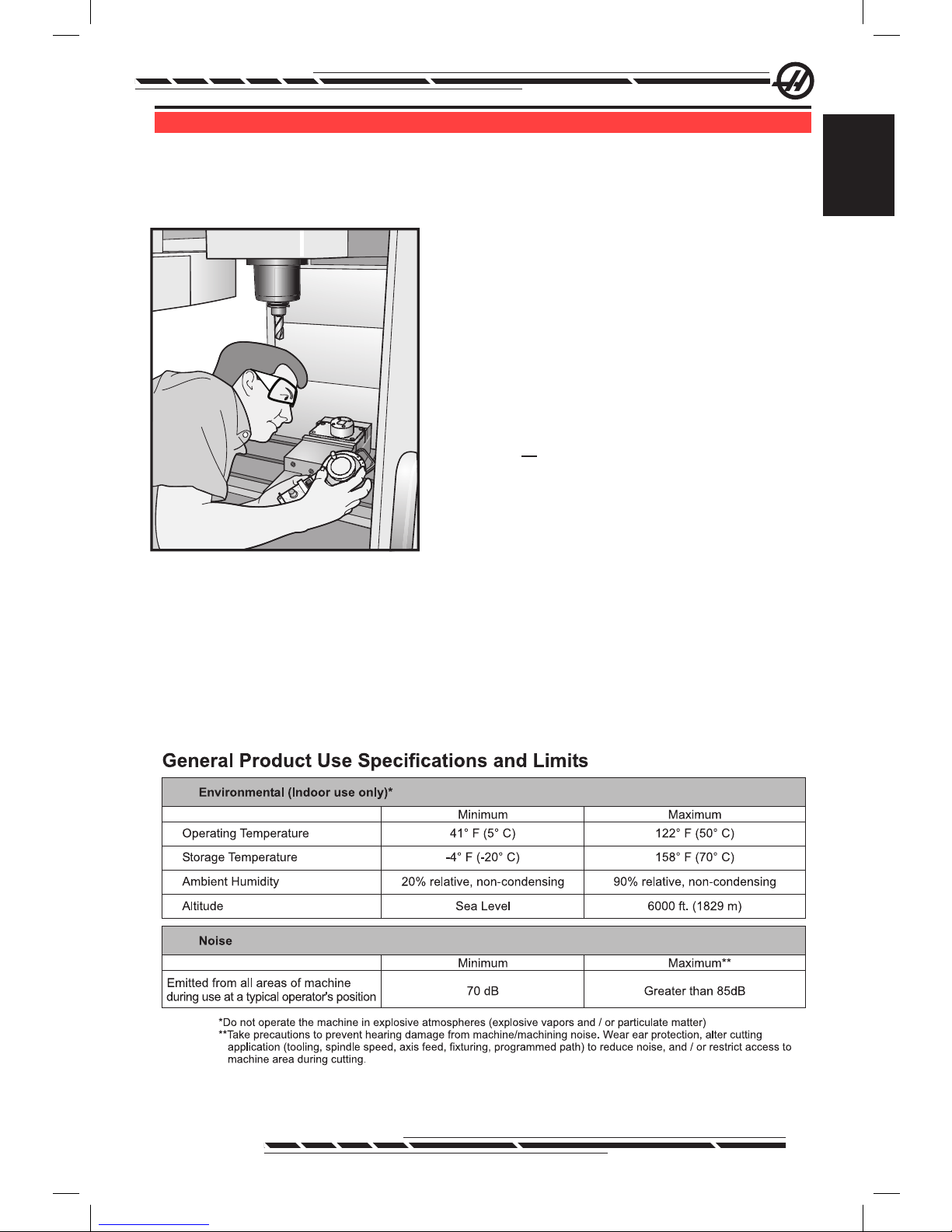
All milling machines contain hazards from rotating cutting tools, belts and pulleys, high voltage electricity, noise, and compressed air. When using milling
machines and their components, basic safety precautions should always be
followed to reduce the risk of personal injury and mechanical damage. READ
ALL APPROPRIATE WARNINGS, CAUTIONS, AND INSTRUCTIONS BEFORE OPERATING THIS MACHINE.
Mo d i f i c a t i o n S t o t h e Ma c h i n e
DO NOT modify or alter this equipment in any way. If modications are necessary, all such requests must be handled by Haas Automation, Inc. Any modi-
cation or alteration of any Haas machining center could lead to personal injury
and/or mechanical damage and will void your warranty.
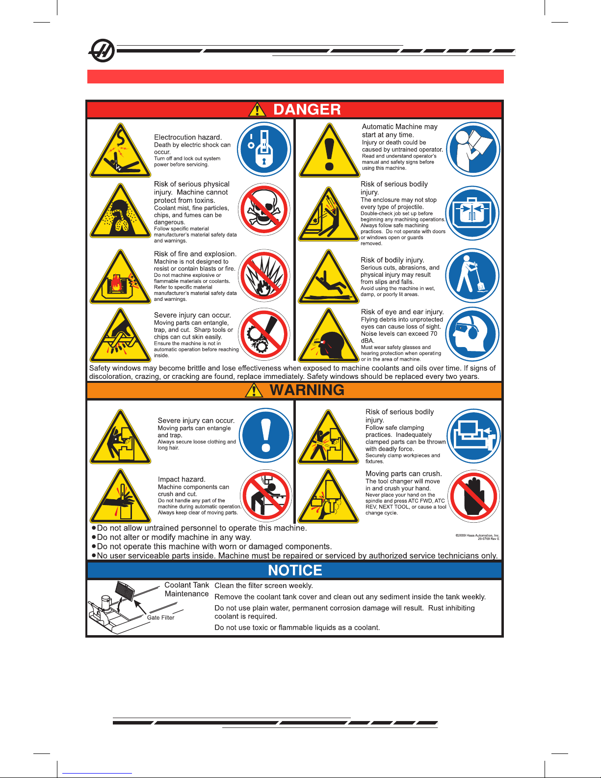
Sa f e t y de c a l S
To help ensure that CNC tool dangers are quickly communicated and understood, hazard symbol decals are placed on Haas Machines in locations where
hazards exist. If decals become damaged or worn, or if additional decals are
needed to emphasize a particular safety point, contact your dealer or the Haas
factory. Never alter or remove any safety decal or symbol.
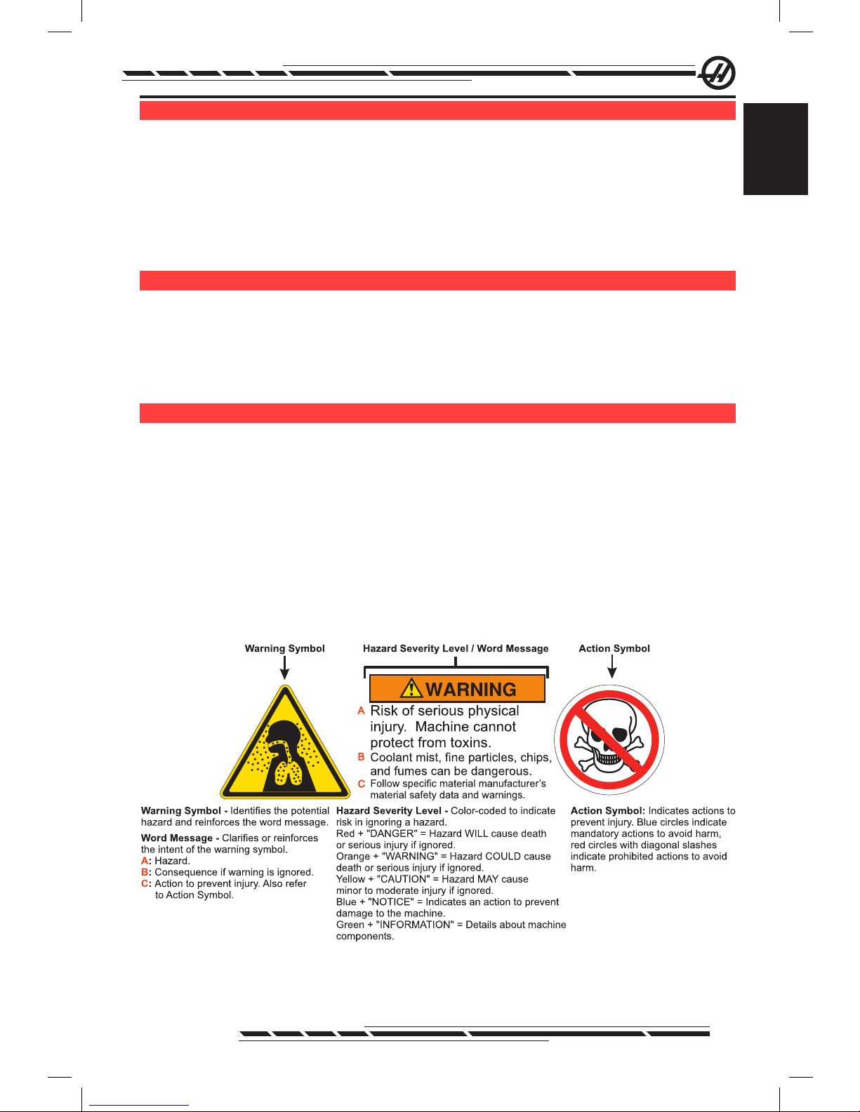
Each hazard is dened and explained on the general safety decal, located at
the front of the machine. Particular locations of hazards are marked with warning symbols. Review and understand the four parts of each safety warning, explained below, and familiarize yourself with the symbols on the following pages.
.
Page 15
6
96-8000 Rev AC
May 2010
Mi l l Wa r n i n G de c a l S
.
Page 16
7
96-8000 Rev AC
May 2010
Safety
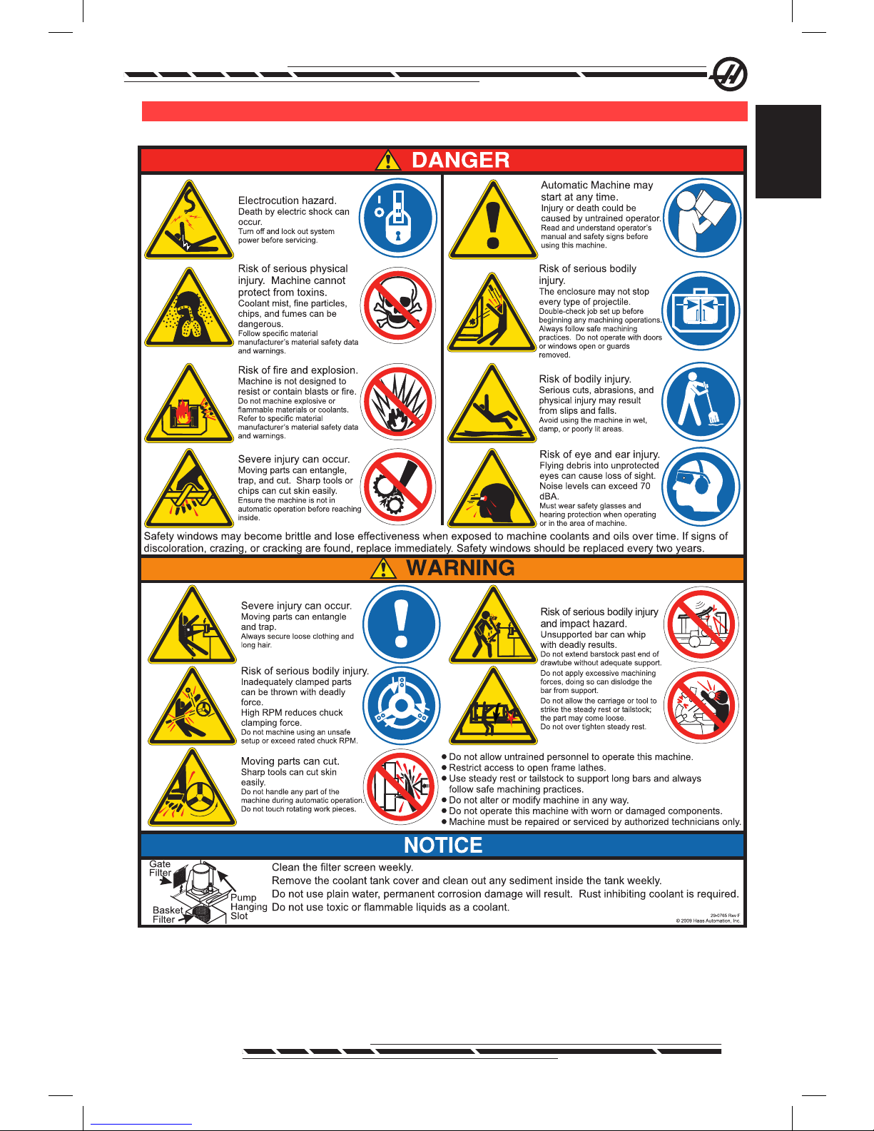
la t h e Wa r n i n G de c a l S
.
Page 17

8
96-8000 Rev AC
May 2010
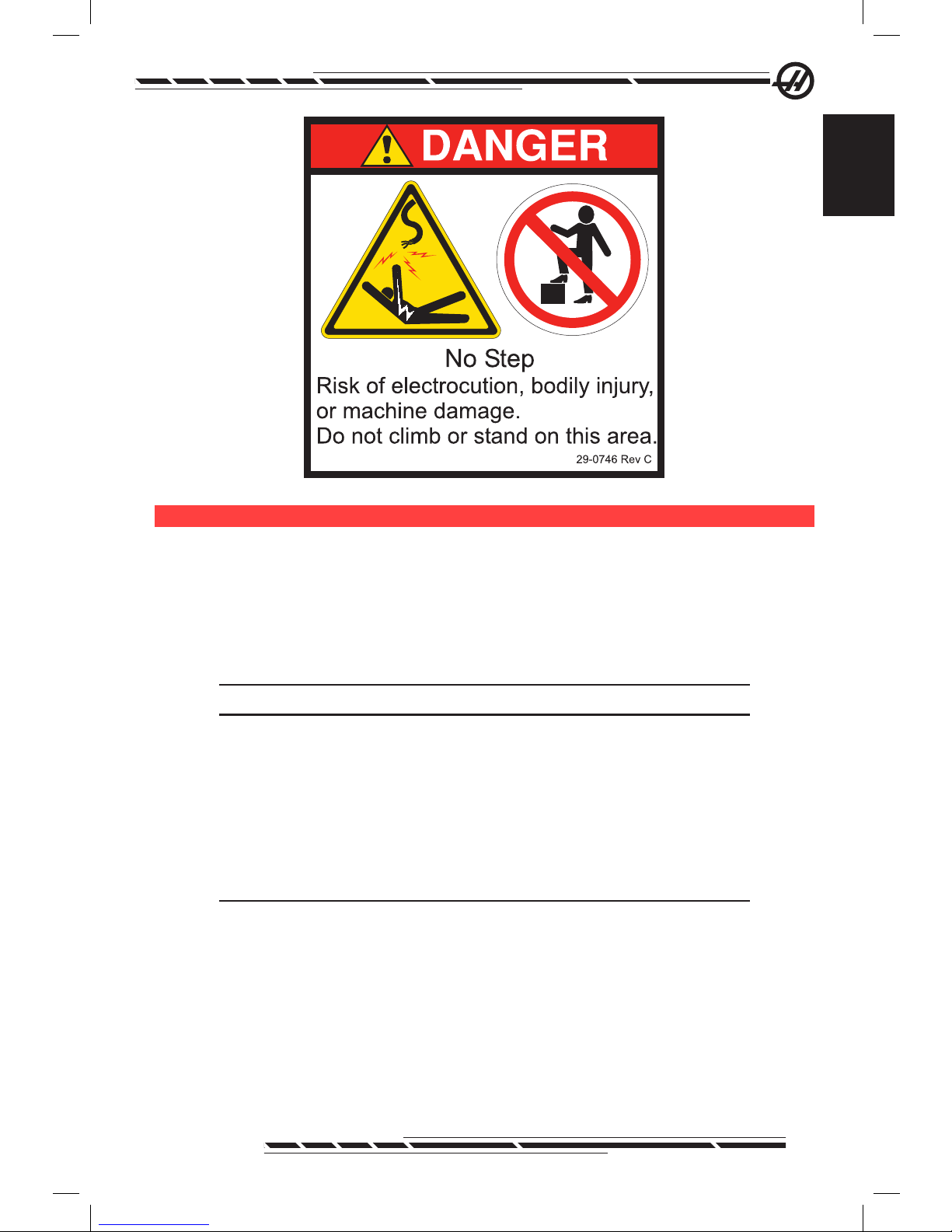
ot h e r Sa f e t y de c a l S
Other decals may be found on your machine, depending on the model and options installed:
.
Refer to the APC Sectionfor further explanation.
Page 18
9
96-8000 Rev AC
May 2010
Safety
.
de c l a r a t i o n o f Wa r n i n G S , ca U t i o n S , a n d no t e S
Throughout this manual, important and critical information is prefaced with the
word “Warning”, “Caution” and “Note”
Warnings are used when there is an extreme danger to the operator and/or to
the machine. Take all steps necessary to heed the warning given. Do not continue if you cannot follow the warning instructions. An example warning is:
WARNING! Never put hands between tool changer and spindle head.
Cautions are used when there is the potential for minor personal injury or mechanical damage, for example:
CAUTION! Power down the machine before performing any maintenance tasks.
Notes give additional information to the operator about a particular step or
procedure. This information should be taken into consideration by the operator
as the step is performed to ensure there is no confusion, for example:
NOTE: If machine is equipped with the optional extended Z-clearance
table, follow these guidelines:
Page 19

10
96-8000 Rev AC
May 2010
fcc co M P l i a n c e
This equipment has been tested and found to comply with the limits for a Class
A digital device, pursuant to Part 15 of the FCC Rules. These limits are de-
signed to provide reasonable protection against harmful interference when the
equipment is operated in a commercial environment. This equipment generates, uses, and can radiate radio frequency energy and, if not installed and
used in accordance with the instruction manual, may cause harmful interference to radio communications. Operation of this equipment in a residential
area is likely to cause harmful interference in which case the user will be
required to correct the interference at his own expense.
Page 20
11
96-8000 Rev AC
May 2010
Introduction
introdUction
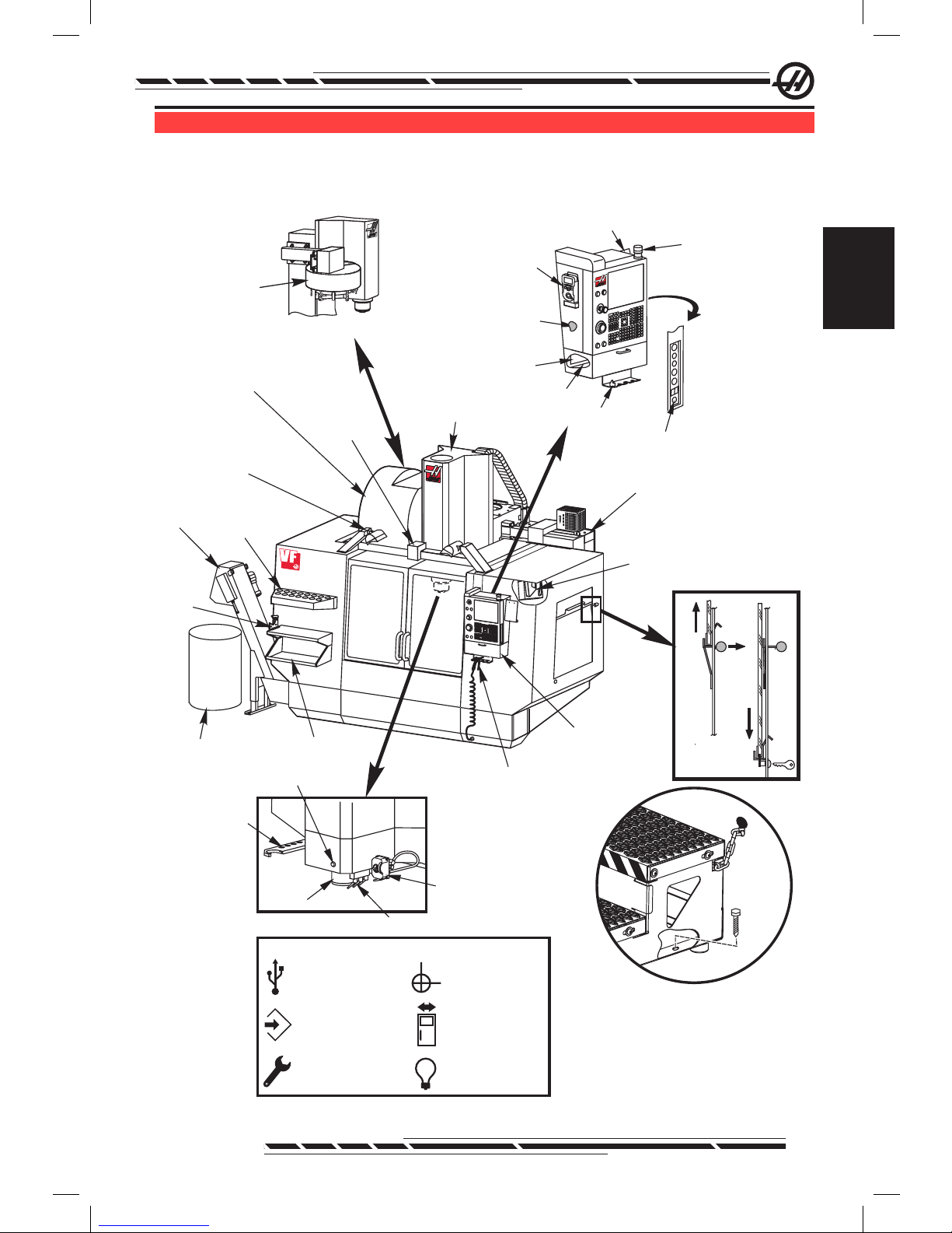
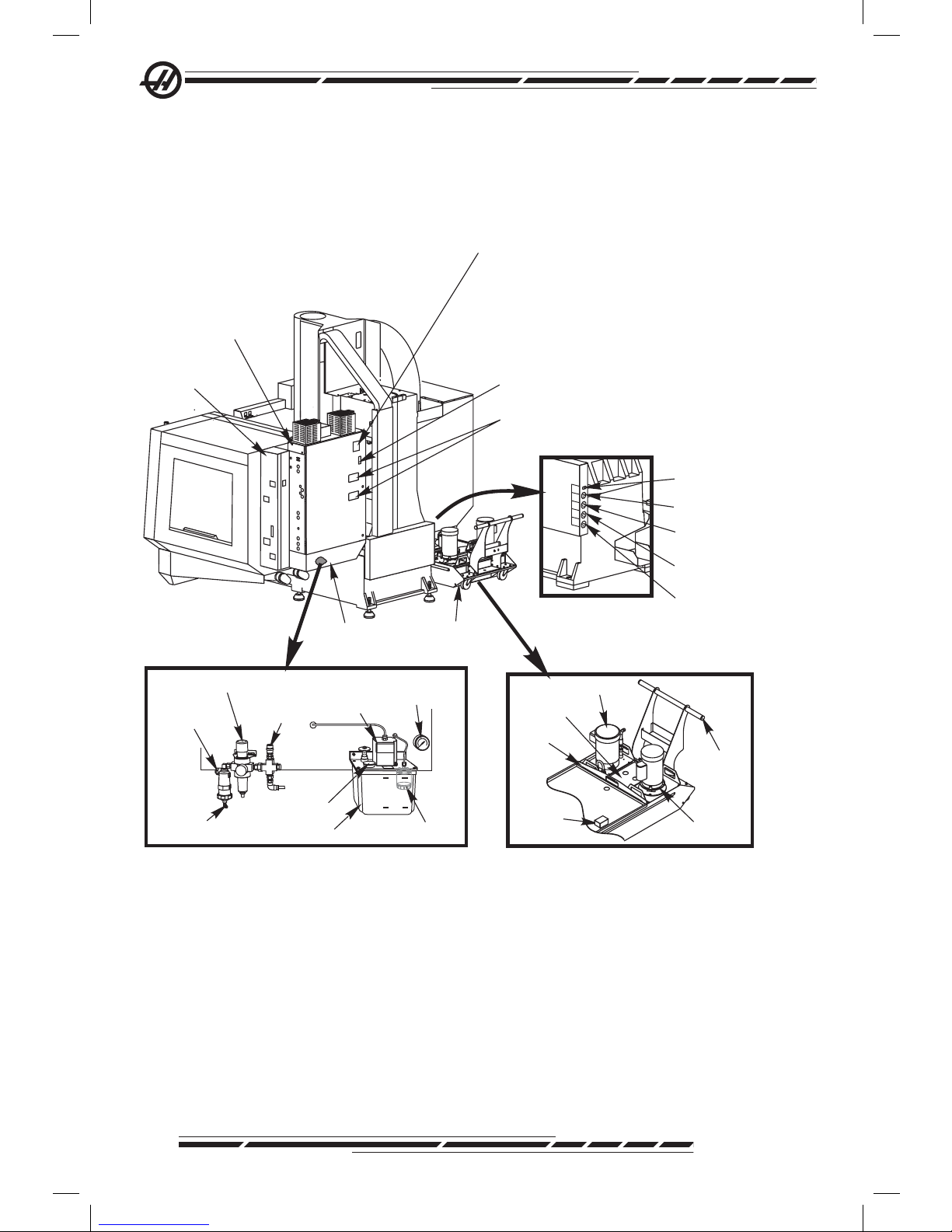
The following is a visual introduction to a HAAS mill. Some of the features
shown will be highlighted in their appropriate sections.
.
Tool Changer
(Umbrella Type)
Spindle
Optional
P-Cool
Assembly
Coolant Nozzles
SMTC
Double Arm
Tool Release Button
V
F
Work Beacon
Clip Board
Operator Manual
& Assembly Data
(Stored inside)
Vise Handle
Holder
Hold to Run
G&MCode
Reference List
Remote Jog
Control
Tool Tray
1
2
3
4
View Rotated 90° CCW
View Rotated 90° CCW
Control
Pendant
Servo
Autodoor
Opener
(Optional)
Chip
Conveyor
(Optional)
Side Mount Tool
Changer (SMTC)
Spindle Head
Assembly
Tool
Holding
Vise
Tool Tray
2X High Intensity Lights
2 Switches:1on Lights
1on Header Bar
(Optional)
Front Work Table
Chip
Container
Air Gun
2X Work Light
Electrical
Control Box
Secure Work Platform to Machine
Using Chains to Enclosure and/or Bolts
to the Floor
See
Below
Pendant Side Panel Symbols
2
USB
Write to Memory
(Lock/Unlock)
Setup Mode
(Lock/Unlock)
Second
Home
Autodoor
Override
Light Toggle
(x2)
Page 21
12
96-8000 Rev AC
May 2010
.
OilReservoir
OilPump
Oil Filter
Air Filter/Regulator
Air/Lube Panel Cover Removed
MIN
MAX
Oil Fill
(ToMax Mark)
OilPressure
Gauge
Hose Barb
(Shop Air)
AirNozzle
Air Line
Auxiliary Air
Port
Model
Serial Number
Date of Manufacture
Voltage
Phase
Hertz
Full Load
Largest Load
Short Circuit Interrupting Capacity
Wiring Diagram
Short Circuit Current
Arc Flash Rating
NEMA Type1Enclosure for Indoor
Use Only.
Over current protection provided
at machine supply terminals)
Made in USA
Coolant Tank
Assembly
Control Box Fan
(runs intermittenly)
MainCircuit
Breaker Switch
Air Lube Panel
Assembly
Electrical
Control Box
Coolant Level
Sensor
Coolant (Optional)
Auxiliary Coolant
(Optional)
Washdown (Optional
Conveyor (Optional)
View Rotated 90°CW
Smart Lube
Panel Assembly
Handle
Standard
Pump
Strainer
SingleLid
Level
Sensor
TSC Pump
DATA PLATE
Page 22
13
96-8000 Rev AC
May 2010
Introduction
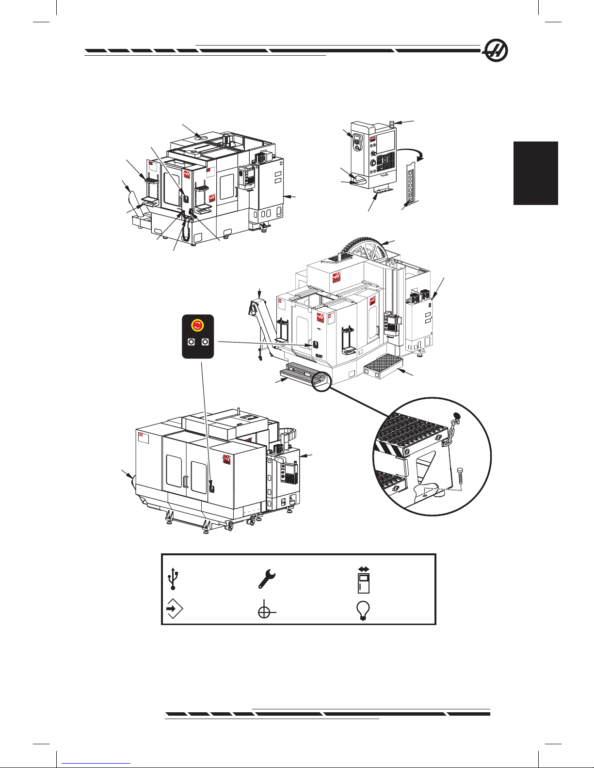
Horizontal Mills
.
MainElectrical
Control Box
MainElectrical
Control Box
Chip
Chute
Front
Table
Emergency
Stop Switch
Tool Holding Vise
Air Gun
EC-300 -400 -500
EC-550 -630
Work Beacon
Remote Jog
Handle
Vise Handle Holder
Holdto Run
G&MCode
Reference List
Tool Crib
Nozzle Holding
Bracket
Tool Tray
Chip Conveyor
Side Mount Tool
Changer (SMTC)
EC
EC
Side Mount Tool
Changer (SMTC)
Platform Assy
(Operator Side)
Platform Assy
(Front Side)
MainElectrical
Control Box
Chip
Chute
1600
EC
30HP
GEAR
D
RIVE
2-SPEED
INDEXING
FACE-GEAR
COUPLING
EC-1600 -2000 -3000
ROTARYINDEXPARTREADY
EMERGENCYSTOP
Sub-Panel
Buttons:
Emergency Stop
RotaryIndex
Pallet Ready
See Pallet
Changer Section
Secure Work Platform to Machine
Using Chains to Enclosure and/or Bolts
to the Floor
Pendant Side Panel Symbols
2
USB
Write to Memory
(Lock/Unlock)
Setup Mode
(Lock/Unlock)
Second
Home
Autodoor
Override
Light Toggle
(x2)
See Below
Page 23
14
96-8000 Rev AC
May 2010
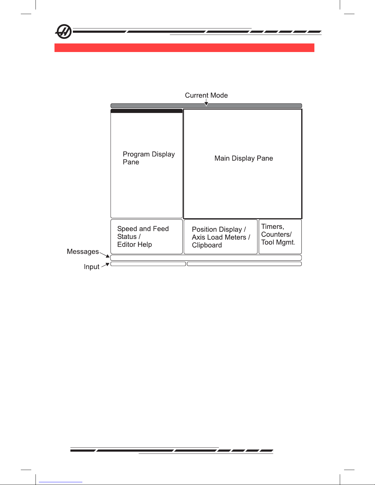
co n t r o l di S P l a y a n d Mo d e S
The control display is organized into panes that vary depending on the current
control mode, and on what display keys are used. The following illustration
shows the basic display layout:
.
Interaction with data can be carried out only within the currently active pane.
Only one pane is active at any given time, and it is indicated with a white back-
ground. For example, to work with the Tool Offsets table, rst make the table
active by pressing the Offset key until it displays with a white background. Then
make changes to the data. Changing the active pane within a control mode is
typically done with the display keys.
Control functions are organized into three modes: Setup, Edit, and Operation.
Each mode provides all of the necessary information to perform tasks that fall
under the mode, organized to t in one screen. For example, Setup mode displays both the work and tool offset tables, and position information. Edit mode
provides two program editing panes and access to the VQCP and IPS/WIPS
systems (if installed).
Access modes using the mode keys as follows:
Setup: ZERO RET, HAND JOG keys. Provides all control features for machine
setup.
Edit: EDIT, MDI/DNC, LIST PROG keys. Provides all program editing, man-
agement, and transfer functions.
Page 24
15
96-8000 Rev AC
May 2010
Introduction
Operation: MEM key. Provides all control features necessary to make a part.
The current mode is shown in the title bar at the top of the display.
Note that functions from other modes can still be accessed from within the
active mode by using the display keys. For example, while in Operation mode,
pressing OFFSET will display the offsets tables as the active pane; toggle the
offset display using the OFFSET key. pressing PROGRM CONVRS in most
modes will shift to the edit pane for the current active program.
na v i G a t i n G ta b b e d Me n U S
Tabbed menus are used in several control functions, such as Parameters, Settings, Help, List Prog, and IPS. To navigate these menus, use the arrow keys
to select a tab, then press Enter to open the tab. If the selected tab contains
sub-tabs, use the arrow keys and Enter to select the appropriate one.
To go up one tab level, press Cancel.
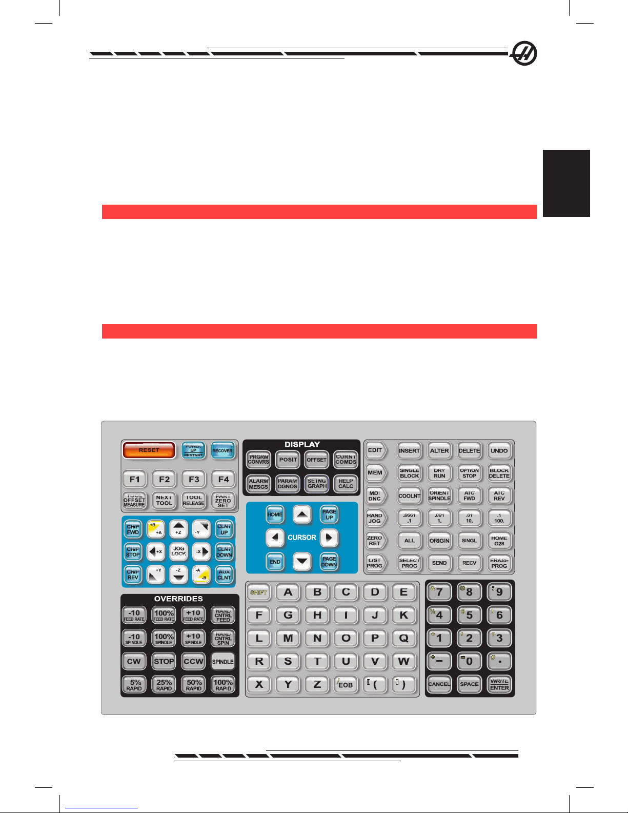
Pe n d a n t Ke y b o a r d in t r o d U c t i o n
The keyboard is broken up into eight sections: Function Keys, Jog Keys, Override Keys, Display Keys, Cursor Keys, Alpha Keys, Mode Keys and Number
Keys. In addition there are miscellaneous keys and features located on the
pendant and keyboard which are described briey.
.
Power On - Turns the machine on.
Page 25

16
96-8000 Rev AC
May 2010
Power Off - Turns the machine off.
Emergency Stop - This stops all axes motion, stops the spindle and tool
changer, and turns off the coolant pump.
Jog Handle - This is used to jog all axes. Can also be used to scroll through
program code or menu items while editing.
Cycle Start - Starts a program. This button is also used to start a program
simulation in Graphics mode.
Feed Hold - Will stop all axis motion. Note: Spindle will continue to turn during
cutting.
Reset - Will stop the machine (axes, spindle, coolant pump, and tool changer
are stopped). This is not a recommended method to stop the machine, as it
may be difcult to continue from that point.
Power Up / Restart - On most machines, when this key is pressed, the axes
will return to the machine zero position and a tool change may occur. See Setting 81 in the Settings chapter for more information.
Recover - This button aids the operator in recovering the tool changer from an
abnormal stop. See the tool changer section for more information.
Memory Lock Key Switch - This switch prevents the operator from editing
programs and from altering settings when turned to the locked position, and
the below-listed settings are turned on. The following describes the hierarchy of
locks:
Key switch locks Settings and all programs.
Setting 7 locks parameters.
Setting 8 locks all programs.
Setting 23 locks 9xxx programs.
Setting 119 locks offsets.
Setting 120 locks macro variables.
Second Home Button - This button will rapid all axes to the coordinates specied in work Offset G154 P20. The sequence is as follows: First, the Z axis is
returned to machine zero, then the X and Y axes are moved, then the Z axis is
moved to its second home position. This feature will work in any mode except
DNC.
Work Light Switch - This switch will turn on the work light inside of the ma-
chine.
Keyboard Beeper - Located at the top of the parts tray. Adjust the volume by
turning the cover.
Page 26

17
96-8000 Rev AC
May 2010
Introduction
fU n c t i o n Ke y S
F1- F4 Keys - These buttons have different functions depending on mode of
operation. See the specic mode section for further descriptions and examples.
Tool Offset Meas (Tool Offset Measure) - Used to record tool length offsets
during part setup.
Next Tool - Used to select the next tool from the tool changer. Used after
pressing Tool Offset Measure in Setup.
Tool Release - Releases the tool from the spindle when in MDI mode, zero
return mode, or handle jog mode.
Part Zero Set - Used to record work coordinate offsets during part setup (see
Setting Offsets in the Operation section).
Jo G Ke y S
Chip FWD (Chip Auger Forward) - Starts optional chip auger in the “Forward”
direction, moving chips out of the machine.
Chip Stop (Chip Auger Stop) - Stops auger movement.
Chip REV (Chip Auger Reverse) - Starts the optional chip auger in the “Re-
verse” direction, which is useful in clearing jams and debris from the auger.
X/-X, Y/-Y, Z/-Z, A/-A and B/-B (axis keys)- Allows manually jogging of axis by
holding down the individual button or by pressing the desired axis button and
using the jog handle.
Jog Lock - Works with the axes buttons. Press jog lock and then an axis button and the axis will move to maximum travel or until jog lock is pressed again.
CLNT Up (Coolant Up) - Moves the optional Programmable Coolant (P-Cool)
nozzle up.
CLNT Down (Coolant Down) - Moves the optional P-Cool nozzle down.
AUX CLNT (Auxiliary Coolant) - Pressing this key while in MDI mode only will
turn on the optional Through the Spindle Coolant (TSC) system; pressing it a
second time will turn off TSC.
ov e r r i d e Ke y S
These keys give the user the ability to override the speed of non-cutting (rapid)
axes motion, programmed feeds and spindle speeds.
-10 - Decreases current feedrate by 10%.
100% - Sets overridden feedrate to programmed feedrate.
+10 - Increases current feedrate by 10%.
Page 27

18
96-8000 Rev AC
May 2010
-10 - Decreases current spindle speed by 10%.
100% - Sets overridden spindle speed to programmed speed.
+10 - Increases current spindle speed by 10%.
Hand Cntrl Feed (Handle Control Feedrate) - Pressing this button allows the
jog handle to be used to control the feedrate in ±1% increments.
Hand Cntrl Spin (Handle Control Spindle) - Pressing this button allows the jog
handle to be used to control spindle speed in ±1% increments.
CW - Starts the spindle in the clockwise direction. This button is disabled on
CE (export) machines.
CCW - Starts the spindle in the counterclockwise direction. This button is dis-
abled on CE (export) machines.
The spindle can be started or stopped with the CW or CCW buttons any
time the machine is at a Single Block stop or the Feed Hold button has been
pressed. When the program is restarted with Cycle Start, the spindle will be
turned back on to the previously dened speed.
STOP - Stops the spindle.
5% / 25% / 50% / 100% Rapid - Limits machine rapids to the value on the key.
The 100% Rapid button allows maximum rapid.
Override Usage
The feedrate can be varied from 0% to 999% of the programmed value while in
operation. This is done with the feedrate +10%, -10% and 100% buttons. The
feedrate override is ineffective during G74 and G84 tapping cycles. Feedrate
override does not change the speed of any auxiliary axes. During manual jogging, the feedrate override will adjust the rates selected from the keypad. This
allows for ne control of the jog speed.
The spindle speed can also be varied, from 0% to 999%, using the spindle
overrides. It is also ineffective for G74 and G84. In the Single Block mode, the
spindle may be stopped. It will automatically start up upon continuing the pro-
gram (pressing Cycle Start).
By pressing the Handle Control Feedrate key, the jog handle can be used to
control feedrate from 0% to 999% in ±1% increments. By pressing the Handle
Control Spindle key, the jog handle can be used to control spindle speed in
±1% increments (from 0% to 999%).
Rapid moves (G00) may be limited to 5%, 25%, or 50% of maximum using the
keypad. If the 100% rapid is too fast, it may be set to 50% of maximum by Set-
ting 10.
In the Settings page, it is possible to disable the override keys so that the operator cannot use them. These are Settings 19, 20 and 21.
Page 28

19
96-8000 Rev AC
May 2010
Introduction
The Feed Hold button acts as an override, stopping rapid and feed moves
when it is pressed. The Cycle Start button must be pressed to proceed after a
Feed Hold. The door switch on the enclosure also has a similar result but will
display “Door Hold” when the door is opened. When the door is closed, the
control will be in Feed Hold and Cycle Start must be pressed to continue. Door
Hold and Feed Hold do not stop any auxiliary axes.
The operator can override the coolant setting by pressing the COOLNT button.
The pump will remain either on or off until the next M-code or operator action
(see Setting 32).
Overrides can be reset to defaults with an M06, M30 and/or pressing RESET
(See Settings 83, 87, 88).
di S P l a y Ke y S
Display keys provide access to the machine displays, operational information
and help pages. They are often used to switch active panes within a function
mode. Some of these keys will display additional screens when pressed more
than once.
Prgrm/Convrs - Selects the active program pane in most modes. In MDI/DNC
mode, press to access VQC and IPS/WIPS (if installed).
Posit (Position) - Selects the positions pane, located in the lower center of
most screens. Displays the current axis positions. Toggle between relative positions by pressing the POSIT key. To lter the axes displayed in the pane, type
the letter for each axis to display and press WRITE/ENTER. Each axis position
is displayed in the order indicated.
Offset - Press to toggle between two offsets tables. Select the Tool Offsets
table to display and edit tool length geometry, radius offsets, wear offsets, and
coolant position. Select the Work Offsets table to edit the G-code specied
work offset locations used in programs.
Curnt Comds (Current Commands) - Press PAGE UP / PAGE DOWN to cycle
through menus for Maintenance, Tool Life, Tool Load, Advanced Tool Management (ATM), System Variables, Clock settings and timer / counter settings.
Alarm / Mesgs (Alarms / Messages) - Displays the alarm viewer and message
screens. There are three alarm screens, the rst shows the currently active
alarms (rst press of the Alarm/Mesgs button). Press the Right Arrow key to
view Alarm History. Use the Up and Down Arrow keys to scroll through alarm
history entries, and press F2 to write to a memory device.
Param / Dgnos (Parameters / Diagnostics) - Displays parameters that dene
the machine’s operation. Parameters are organized by category in a tabbed
menu, or to nd a known parameter, type in the number and press the up or
down arrow. Parameters are set at the factory and should not be modied ex-
cept by authorized Haas personnel.
Page 29

20
96-8000 Rev AC
May 2010
A second press of the Param / Dgnos key will display the rst page of diagnostic data. This information is mainly used for troubleshooting by a certied
Haas service technician. The rst page of diagnostic data is discrete inputs and
outputs. Pressing Page Down will display additional pages of diagnostic data.
Setng / Graph (Settings / Graphics) - Displays and allows changing of user
settings. Like Parameters, Settings are organized by category in a tabbed
menu. To nd a known setting, type in the number and press the up or down
arrow.
Pressing the Setng / Graph key a second time enables Graphics mode. In
Graphics mode, the generated tool path of the program is seen and, if necessary, the program can be debugged before running it (See Graphics Mode in
the Operation section)
Help / Calc (Help / Calculator) - Displays help topics in a tabbed menu. Available help includes brief descriptions of G and M codes, denitions of control
features, troubleshooting and maintenance issues. The help menu also in-
cludes several calculators.
Pressing the HELP/CALC key within some modes will call a pop-up help
window. Use this window to access help topics relevant to the current mode,
and also to execute certain functions as noted in the menu. To access the
tabbed menu described above from a pop-up help window, press HELP/CALC
a second time. Press HELP/CALC a third time to return to the display that was
active when Help/CALC was pressed the rst time.
cU r S o r Ke y S
Use Cursor Keys to move to various screens and elds in the control, and for
editing CNC programs.
Home - This button will move the cursor to the top-most item on the screen; in
editing, this is the top left block of the program.
Up / Down Arrows - moves up/down one item, block or eld.
Page Up / Down - Used to change displays or move up/down one page when
viewing a program.
Left Arrow - Used to select individually editable items when viewing a program; moves cursor to the left. It is used to scroll through setting selections.
Right Arrow - Used to select individually editable items when viewing a program; moves cursor to the right. It is used to scroll through setting selections
and moves the zoom window right when in graphics mode.
End - This button generally moves the cursor to the bottom-most item on the
screen. In editing, this is the last block of the program.
Page 30

21
96-8000 Rev AC
May 2010
Introduction
al P h a Ke y S
The alpha keys allow the user to enter the letters of the alphabet along with
some special characters. Some of the special characters are entered by rst
pressing the “Shift” key.
Shift - The shift key provides access to additional characters on the keyboard.
The additional characters are seen in the upper left of some of the alpha and
number keys. Pressing Shift and then the character will enter that character on
the data entry line. When entering text, UPPER CASE is the default, to enter
lower case characters, press and hold the Shift key.
When a control has a fth axis installed, the B axis is selected for jogging by
pressing the Shift button and then the +/-A jog keys.
EOB - This is the End-Of-Block character. It is displayed as a semicolon (;) on
the screen and it signies the end of a program line.
( ) - Parentheses are used to separate CNC program commands from user
comments. They must always be entered as a pair. Note: Any time an invalid
line of code is received through the RS-232 port while receiving a program, it is
added to the program between parenthesis.
/ - The right slash is used in the Block Delete feature and in Macro expressions.
If this symbol is the rst symbol in a block and a Block Delete is enabled, then
that block is ignored at run time. The symbol is also used for division (divide by)
in macro expressions (see the Macro section).
[ ] - Square brackets are used in macro functions. Macros are an optional software feature.
Mo d e Ke y S
Mode keys change the operational state of the CNC machine tool. Once a
mode button is pressed, the buttons in the same row are made available to the
user. The current mode is always displayed at the top center of the display.
EDIT- Selects edit mode. This mode is used to edit programs in control’s mem-
ory. Edit mode provides two editing panes: one for the currently active program,
and another for background editing. Switch between the two panes by pressing
the EDIT key. Press F1 to access help pop-up menus.
Insert - Pressing this button will enter commands into the program in front of
the cursor. This button will also insert the text from the clipboard to the current
cursor location, and is also used to copy blocks of code in a program.
Alter - Pressing this button will change the highlighted command or text to the
newly entered commands or text. This button will also change the highlighted
variables to the text stored in the clipboard, or move a selected block to another location.
Page 31

22
96-8000 Rev AC
May 2010
Delete - Deletes the item that the cursor is on, or deletes a selected program
block.
Undo - Undoes up to the last 9 edit changes, and deselects a highlighted
block.
MEM (Memory) - Selects the memory mode. The screen displays the active
program and other information necessary when making a part.
Single Block - Turns single block on or off. When single block is on, only one
block of the program is executed, for every press of Cycle Start.
Dry Run - This is used to check actual machine movement without cutting a
part. (See the Dry Run section in the Operation Chapter)
Opt Stop (Optional Stop) - Turns on and off optional stops. Also see G103 in
the G-Code chapter.
When this feature is ON and an M01 (optional stop) code is programmed, the
machine will stop when it reaches the M01. The machine will continue once Cycle Start is pressed. However, depending on the look-ahead function (G103), it
may not stop immediately (See block look ahead section). In other words, the
block look-ahead feature may cause the Optional Stop command to ignore the
nearest M01.
If the Optional Stop button is pressed during a program it will take effect on the
line after the highlighted line when the Opt Stop button is pressed.
Block Delete - Turns On/Off block delete function. Blocks with a slash (“/”) as
the rst item are ignored (not executed) when this option is enabled. If a slash
is within a line of code, the commands after the slash will be ignored if this
feature is enabled. Block Delete will take effect two lines after Block Delete is
pressed, except when cutter compensation is used, in this case, block delete
will not take effect until at least four lines after the highlighted line. Processing
will slow down for paths containing block deletes during high-speed machining.
Block Delete will stay active when power is cycled.
MDI/DNC - MDI mode is the “Manual Data Input” mode where a program
can be written but it is not entered into memory. DNC mode “Direct Numeric
Control”, allows large programs to be “drip fed” into the control so it can be
executed (See DNC mode section).
Coolnt (Coolant) - Turns the optional coolant on and off.
Orient Spindle - Rotates the spindle to a given position and then locks the
spindle. Can be used during setup to indicate parts.
ATC FWD / REV - Rotates the tool turret to the next / previous tool. To load a
specic tool into the spindle, enter MDI or hand jog mode, type a tool number
(T8) and press ATC FWD or ATC REV.
Hand Jog - Selects axis jogging mode .0001, .1 - 0.0001 inches (metric
Page 32

23
96-8000 Rev AC
May 2010
Introduction
0.001mm) for each division on the jog handle. For dry run, .1 inches/min.
.0001/.1, .001/1., .01/10., .1/100. - The rst number (top number), when in inch
mode, selects that amount to be jogged for each click of the jog handle. When
the mill is in MM mode the rst number is multiplied by ten when jogging the
axis (e.g. .0001 becomes 0.001mm). The second number (bottom number) is
used for dry run mode and is used to select the speed feedrate and axis motions.
Zero Ret (Zero Return) - Selects Zero Return mode, which displays axis loca-
tion in four different categories, they are; Operator, Work G54, Machine and
Dist (distance) to go. Press POSIT to switch between the categories.
All - Returns all axes to machine zero. This is similar to Power Up/Restart except a tool change will not occur. This can be used to establish the initial axes
zero position.
Origin - Sets selected displays and timers to zero.
Singl (Single) - Returns one axis to machine zero. Press the desired axis letter
and then press the Singl Axis button. This can be used to move a single axis to
the initial axis zero position.
HOME G28 - Returns all axes to zero in rapid motion. Home G28 will also
home a single axis in the same manner as if an axis letter is entered and the
home G28 button is pressed. CAUTION! There is no warning message to alert
the operator of any possible collision. For example, if the Z-axis is in amongst
parts, when X or Y is zeroed, a crash can result.
List Prog (List Programs) - Controls all loading and saving of data in the control.
Select Prog - Makes the highlighted program the active program. Note: The
active program will have an “A” preceding it in the program list. Manage mul-
tiple programs by pressing WRITE/ENTER to place a check mark next to the
desired programs, then press F1 to choose a function.
Send - Transmits programs out the RS-232 serial port.
Recv - Receives programs from the RS-232 serial port.
Erase Prog - Erases the cursor selected program in List Prog mode or the
entire program when in MDI mode.
nU M e r i c Ke y S
The numeric keys give the user the ability to enter numbers and a few special
characters into the control.
Cancel - The Cancel key is used to delete the last character entered.
Space - Used to format comments placed into programs or in the message
Page 33

24
96-8000 Rev AC
May 2010
area.
Write / Enter - General purpose enter key.
- (Minus sign)- Used to enter negative numbers.
. (Decimal Point)- Used for decimal precision.
da t e a n d ti M e
The control contains a clock and date function. To view the time and date,
press the CRNT COMDS key, then Page Up or Page Down until the date and
time appears.
To make adjustments, press Emergency Stop, type the current date (in MMDD-YYYY format) or current time (in HH:MM format), and press WRITE/ENTER. Reset Emergency Stop when nished.
SP i n d l e Wa r M -UP Pr o G r a M
If any spindle has been idle for more than 4 days, it must be thermally cycled
prior to operation. This warm-up will prevent possible overheating of the spindle
due to the settling of lubrication. A 20-minute warm-up program (number
O02020) is supplied with the machine which will bring the spindle up to speed
slowly, allowing the spindle to thermally stabilize. This program can be used
daily for spindle warm-up prior to high-speed use.
co o l a n t le v e l Ga U G e
The coolant level is displayed in the upper right of the screen in MEM mode, or
on the CURNT COMDS screen. A vertical bar shows the status of the coolant.
The display will ash when the coolant reaches a point that could cause intermittent coolant ow.
Wo r K be a c o n
The beacon light provides quick visual conrmation of the machine’s current
status. There are four different beacon states:
Off - The machine is idle.
Solid Green - The machine is running.
Flashing Green - The machine is stopped, but is in a ready state. Operator
input is required to continue.
Flashing Red - A fault has occurred, or the machine is in Emergency Stop.
Page 34

25
96-8000 Rev AC
May 2010
Introduction
oP t i o n S
200 Hour Control Option Try-Out
Options that normally require a unlock code to activate (Rigid Tap, Macros,
etc.) are activated and deactivated as desired by entering the number “1”
instead of the unlock code to turn it on. Enter a “0” to turn off the option. An
option activated in this manner is automatically deactivated after a total of 200
power-on hours. Note that the deactivation only occurs when power to the
machine is turned off, not while it is running. An option can be activated per-
manently by entering the unlock code. Note that the letter “T” will be displayed
to the right of the option on the parameter screen during the 200 hour period.
Note that the safety circuit option is an exception; it can be turned on and off
only by unlock codes.
To enter a 1 or 0 into the option, press the Emergency Stop button in and
turn setting 7 (Parameter Lock) off. When the option reaches 100 hours the
machine will give an alarm warning that the try out period is almost over. To
permanently activate an option contact your dealer.
Rigid Tapping
Synchronized tapping eliminates the need for expensive, oating tap holders,
and prevents lead-thread distortion and start-thread pullout.
Macros
Create subroutines for custom canned cycles, probing routines, operator
prompting, math equations or functions, and family-of-parts machining with
variables.
Rotation and Scaling
Use rotation in conjunction with work offset probing to speed workpiece setup,
or to rotate a pattern to another location or around a circumference, etc. Use
scaling to reduce or enlarge a toolpath or pattern.
Spindle Orientation
The Spindle Orientation option allows spindle positioning to a specic, programmed angle, using the standard spindle motor and the standard spindle
encoder for feedback. This option provides inexpensive, accurate (0.1 degree)
positioning.
High Speed Machining
High speed machining makes it possible for an increase in the removal rate of
material, improve surface nish, and reduce cutting forces which will reduce
machining costs and extend the life of the tools.
High Speed Machining is most often required for the machining of smoothly
sculpted shapes as is typical of mold making. The Haas High Speed Machining
option increases the amount of lookahead to 80 blocks and allows full speed
(500 inches per minute) blending of feed strokes.
It is important to understand that high speed machining works best with
Page 35

26
96-8000 Rev AC
May 2010
smoothly blended shapes where the feed rate can remain high through the
blend of one stroke to the next. If there are sharp corners, the control will always need to slow down or corner rounding will occur.
The affect that blending of strokes can have on feed rate is always to slow
down motion. The programmed feed rate (F) is thus a maximum and the con-
trol will sometimes go slower than that in order to achieve the required accuracy.
Too short of a stroke length can result in too many data points. Check how the
CAD/CAM system generates data points to insure that it does not exceed 1000
blocks per second.
Too few data points can result in either “facetting” or blending angles which
are so great that the control must slow down the feed rate. Facetting is where
the desired smooth path is actually made up of short, at, strokes that are not
close enough to the desired smoothness of the path.
High Speed Tooling – The tool holders should be an AT-3 or better with a
nylon back-up screw. The tolerances maintained in the AT-3 design are the
minimum that would be recommended for a high speed process. The nylon
back-up screw increases collet grip on the tool and creates a better seal to aid
in coolant transfer.
Use single angle collet chucks and collets for best grip and concentricity. These
collet systems are made up of a long single angle located in the holder. The
angle per side should be eight degrees or less for best results. Avoid double
angle collet systems when maximum rigidity and close tolerance are dictated.
It is recommended that minimum engagement of 2/3 of the full length of the
bore in the double split single angle collet. However for better results 3/4 to full
engagement is preferred if possible.
High Intensity Lighting - Auxiliary lights provide bright illumination of the work
area. The lights operate automatically when doors open and close, or can be
activated manually using the switch on the side of the control pendant. Turn the
switch on and the lights will turn on when he door is opened and off when the
door is clsed. Set the switch to off and the lights will not turn on when the door
is opened. See setting 238.
re M o t e Jo G ha n d l e
The Enhanced Color Remote Jog Handle (RJH) features a color liquid crystal
display (LCD) and controls for increased functionality. It also features a highintensity LED ashlight.
Page 36

27
96-8000 Rev AC
May 2010
Introduction
.
Holster
Color LCD
Axis Selection
Thumb Knob
Function Keys
Arrow Keys
Cycle
Start
Pulse Wheel
Feed
Hold
Shuttle Jog
Knob
Refer to the section on offsets and machine operation for more information on
those topics.
LCD – Displays machine data and the RJH-E/C interface.
Function Keys (F1-F5) - Variable-function keys. Each key corresponds to a
label at the bottom of the LCD screen. Pressing a function key will perform or
toggle the corresponding menu. Toggled functions are highlighted when on.
Cycle Start - Starts programmed axis motion.
Feed Hold - Stops programmed axis motion.
Arrow Keys - Used to navigate between menu elds (up/down) and to select
pulse jog rates (left/right).
Pulse Wheel - Jogs a selected axis by the selected increment. Works like the
jog handle on the control.
Shuttle Jog - Rotates up to 45 degrees CW or CCW from center, and returns
to center when released. Used to jog axes at variable speeds. The farther the
shuttle jog is rotated from the center position, the faster the axis moves. Allow
the knob to return to the center position to stop motion.
Axis Select - Used to select any of the available axes for jogging. The selected
axis is displayed at the bottom of the screen. The far right position of this selec-
tor accesses the auxiliary menu.
Removing the unit from the cradle/holster powers it on and turns over jogging
control from the pendant to the Remote Jog Handle (The hand wheel on the
pendant is disabled).
NOTE: The pendant must be in Hand Jog mode (Setup).
Place the Remote Jog Handle back in its cradle/holster to power it off and
return jogging control to the pendant.
The pulse knob and shuttle knob function as scrollers to change the value of a
Page 37

28
96-8000 Rev AC
May 2010
user-denable eld such as tool offset, length, wear, etc.
Built-in “Panic” Function — Press any key during axis motion to instantly
stop the spindle and all axis motion. Pressing Feed Hold while the spindle is in
motion and the control is in Handle Jog mode will stop the spindle. The mes-
sage “Button pressed while axis was moving—Reselect Axis” appears on
the display. Move the axis selection knob to a different axis to clear.
If the axis selection knob is moved while the shuttle jog is turned, the message
“Axis selection changed while axis was moving—Reselect Axis” appears
on the display, and all axis motion stops. Move the axis selection knob to a different axis to clear the error.
If the shuttle jog knob is turned from its centered position when the Remote Jog
Handle is removed from its cradle/holster, or when the control mode is changed
to a mode with motion (for instance, from MDI to Handle Jog mode), the message “Shuttle off center—No Axis selected” appears on the display and no
axis motion will occur. Move the axis selection knob to clear the error.
If the pulse jog knob is rotated while the shuttle jog knob is in use, the message
“Conicting jog commands— Reselect Axis” appears on the Remote Jog
Handle display, and all axis motion stops. Move the axis selection knob to a different axis to clear the error, then back to reselect the previously selected axis.
NOTE: If any of the above errors fail to clear when the axis selection knob
is moved, there may be a problem with the shuttle jog knob. Contact Haas
service for repair/replacement.
If contact between the Remote Jog Handle and the control is broken for any
reason (cable cut or disconnected, etc.), all axis motion stops. When reconnected, the message “RJH / Control Communication Fault —Reselect Axis”
appears on the Remote Jog Handle display. Move the axis selection knob to
clear the error. If the error does not clear, place the unit in its cradle/holster,
wait for it to power off, and then remove from the cradle/holster.
Page 38

29
96-8000 Rev AC
May 2010
Introduction
RJH Menus
.
ADJST
Set Tool Offsets
Tool in spindle 1
Tool offset: 1
Length: 4.0470
Coolant pos: 15
Z 0.0000
.0001-.001 --.1.01
TOOL COOL WORK>
Left/Right cursor to change pulse
jog rate (current highlighted)
Current Mode
and ContextSensitive Help
Messages
Currently Selected
Axis and Position
Function Keys (Vary with mode)
Working Data Area
(Display Varies)
Next Screen
Up/down arrows
to select fields
Change value with
Pulse/Shuttle
Knob
SET Z
RJH Manual Jogging
This menu contains a large display of the current machine position. Turning the
shuttle jog or pulse knob will move the currently selected axis by the curently
selected jog increment. Change the jog increment with the left/right arrow keys.
Press OPER, WORK, MACH, or TO GO to change the coordinate system (current highlighted). To zero the operator position, press the function key under
OPER to select the position, then press the function key again (it now reads
ZERO).
.
WORK
Manual Jogging
X: 0.0000 in
Y: 0.0000 in
Z: 0.0000 in
.0001-.001 --.1.01
MACH TOOL>
OPER
TO GO
Manual Jogging Display
Page 39

30
96-8000 Rev AC
May 2010
RJH Tool Offsets
Use this menu to set and check tool offsets. Select elds using the function
keys and change values using the pulse or shuttle knob. Select axes using the
thumb knob. The axis line (at the bottom of the display) must be highlighted
to jog that axis. Press ENTER to set the current Z-axis position into the offset
table. To make adjustments to table values, press ADJST, use the pulse or
shuttle knob to select the amount to increase or decrease the value (use the
left and right arrows to change the increment), then press ENTER to apply the
adjustment. Press TOOL to change the tools, and press COOL to change the
coolant position for the selected tool.
CAUTION: Stay clear of the spindle when changing tools.
.
ADJST
Set Tool Offsets
Tool in spindle 1
Tool offset: 1
Length: 4.0470
Coolant pos: 15
Z 0.0000
.0001-.001 --.1.01
TOOL COOL WORK>
SET Z
Setting Tool Offsets Display
rJh Wo r K of f S e t S
Press WK CS to change the work offset G code. Manually jog the selected axis
with the shuttle or pulse knob when the axis eld at the bottom of the screen
is highlighted. Press SET to set the current position of the current axis into
the work offset table. Move the axis selector to the next axis and repeat the
process to set that axis. To make adjustments to a set value, move the axis
selector to the desired axis. Press ADJST and use the pulse or shuttle knob
to increase or decrease the adjustment value, then press ENTER to apply the
adjustment.
Page 40

31
96-8000 Rev AC
May 2010
Introduction
.
ADJST
Set Work Offsets
Work CS G52
X: 0.0000
Y: 0.0000
Z: 0.0000
X 0.0000
.0001-.001 --.1.01
WK CS JOG>
SETX
Setting Work Offsets Display
Auxiliary Menu
The RJH auxiliary menu features controls for machine coolant and the RJH
ashlight. Access the menu by moving the axis selector to the far right position (indicated by a page icon molded into the RJH case). Toggle the available
features by pressing the corresponding function key.
.
LIGHT
CLNT
Auxiliary Menu
Flash Light: OFF
Coolant: OFF
UTIL>
Utility Menu
RJH-C Firmware Version:
0.01g
RJH-C Font Version:
RJH-C
RJH-C Font ID 5
Main Build Version:
VER M16.02x
AUX>
Auxiliary Menu Utility Menu
UTIL Menu
Accesses information about the current conguration of the RJH. This information is used for diagnostic purposes by service technicians. Press AUX to
return to the Auxiliary Menu.
Program Display (Run Mode)
This mode displays the currently running program. Enter run mode by pressing MEM or MDI on the control pendant. The tab options at the bottom of the
screen provide controls for coolant on/off, single block, optional stop, and block
delete. Toggled commands such as COOL will appear highlighted when turned
on. The CYCLE START and FEED HOLD buttons function just as the buttons on the pendant. Return to jogging by pressing HAND JOG on the control
pendant, or place the Remote Jog Handle back in the cradle/holster to continue
running the program from the pendant.
Page 41

32
96-8000 Rev AC
May 2010
Page 42
33
96-8000 Rev AC
May 2010
Operation
o P e r a t i o n
Ma c h i n e Po W e r -UP
Turn the machine on by pressing the Power-On button on the pendant.
The machine will go through a self test and then display either the Messages
screen, if a message was left, or the Alarms screen. In either case the mill will
have one alarm present (102 SERVOS OFF). Pressing the Reset button a
couple times will clear the alarms. If an alarm cannot be cleared the machine
may need servicing, if this is the case call your dealer.
Once the alarms are cleared the machine needs a reference point to start all
operations from; this point is called “Home”. To home the machine, press the
Power-Up Restart button. Caution: Automatic motion will begin once this button
is pressed Keep away from the inside of the machine and the tool changer.
Note that pressing the Power-Up/Reset button will automatically clear alarm
102 if it was present.
After home is found the Current Commands page is displayed, and the machine is now ready to run.
Pr o G r a M M i n G in t r o d U c t i o n
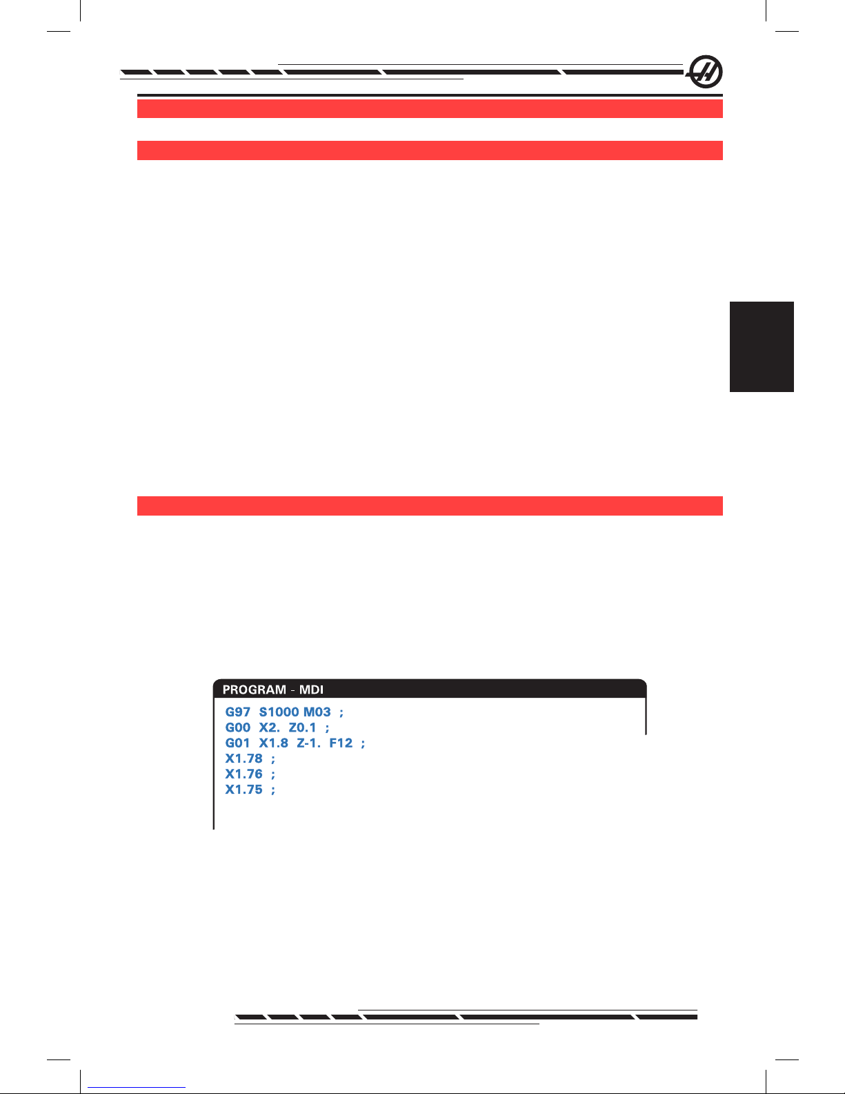
Manual Data Input (MDI)
Manual Data Input (MDI) is a means to command automatic CNC moves without using a formal program.
Press the MDI/DNC key to enter this mode. Programming code is entered by
typing in the commands and pressing Enter at the end of each line. Note that
an End of Block (EOB) will be automatically inserted at the end of each line.
.
To edit the MDI program use the keys to the right of the Edit button. Cursor to
the point that is changing, then the different edit functions can be used.
To enter an additional command to the line, enter the command and press
Enter.
To change a value use the arrow buttons or the jog handle to highlight the com-
Page 43

34
96-8000 Rev AC
May 2010
mand, enter the new command and press Alter.
To delete a command, highlight the command and press Delete.
The Undo key will reverse changes (up to 9 times) that have been made to the
MDI program.
An MDI program can be saved to the memory of the control. To do so cur-
sor to the beginning of the program (or press Home), enter a program name
(programs need to be named using the format Onnnnn; the letter “O” followed
by up to 5 numbers) and press Alter. This will add the program to the list of
programs and clear the MDI page. To re-access the program, press List Prog
and select it.
The data in MDI is retained after exiting MDI mode and when the machine is
turned off.
To clear the current MDI commands press the Erase Prog button.
nU M b e r e d Pr o G r a M S
To create a new program, press LIST PROG to enter the program display and
the list of programs mode. Enter a program number (Onnnnn) and press Select
Prog key or Enter. If the program exists, it will be selected. If it does not yet exist, it will be created. Press Edit to show the new program. A new program will
consist of only the program name and an End of Block (;).
NOTE: Using O09XXX numbers when creating new programs is not
recommended. Macro programs often use numbers in this block, and
overwriting them may cause machine functions to stop working. (Example:
overwriting O09876 will cause G47 operations (engraving) to malfunction).
Numbered programs are retained when the machine is turned off.
Basic Editing of MDI and Numbered Programs
The only difference between an MDI program and a numbered program is the
O code. To edit an MDI program, simply press MDI. To edit a numbered pro-
gram, select it, then press Edit.
The program edit mode includes a type in the program data and press enter.
Program data falls into three categories: addresses, comments or EOBs.
.
To add program code to the existing program, highlight the code that the ad-
Page 44

35
96-8000 Rev AC
May 2010
Operation
ditional code will go in front of, type in the data and press the Insert key. More
than one code, such as X, Y, and Z, can be entered before pressing Insert.
Address data is a letter followed by a numeric value. For example: G04 P1.0.
The G04 commands a dwell (pause) and the P1.0 is the length (1 second) of
the dwell.
Comments can be either alpha or numeric characters, but must be prefaced
with parentheses. For example: (1 second dwell). Comments can be a maximum of 80 characters.
End of Blocks are entered by pressing the EOB button and are displayed as a
semicolon (;). These are used like a carriage return at the end of a paragraph.
In CNC programming an EOB is entered at the end of a string of program code.
An example of a line of code using the three types of commands would be:
G04 P1. (1 second dwell);
There is no need to put any symbols or spaces between the commands. A
space is automatically placed between elements for ease of reading and editing.
To alter characters, highlight the desired portion of the program using the arrow
keys or the jog handle, enter the replacement code, and press Alter.
To remove characters or commands, highlight the text and press Delete.
There is no save command, as the program is saved as each line is entered.
Converting an MDI program to a numbered program
An MDI program can be converted to a numbered program and added to the
list of programs. To do so, cursor to the beginning of the program (or press
Home), enter a program name (programs need to be named using the format
Onnnnn; the letter “O” followed by up to 5 numbers) and press Alter. This will
add the program to the list of programs and clear MDI. To re-access the pro-
gram, press List Prog and select it.
Searching the program
While in MDI, EDIT or MEM mode, the cursor up and down keys can be
used to search the program for specic codes or text. To search for particular
character(s), enter the character(s) on the data entry line (i.e. G40) and press
the cursor up or down keys. The cursor up key will search for the entered item
backwards (towards the start of the program) and the cursor down key will
search forward (towards the end of the program).
Deleting Programs
To delete a program, press LIST PROG. Use the cursor up or down keys to
highlight the program number, then press the ERASE PROG key. Press Y at
the prompt to conrm the deletion or N to back out. Or type in the program
number and press the ERASE PROG key; however, use this option carefully as
Page 45

36
96-8000 Rev AC
May 2010
there is no Y/N prompt and the program will be immediately deleted.
Select ALL at the end of the list and press the ERASE PROG key to delete all
the programs in the list. There are some important programs that are included
with the machine; they are O02020 (spindle warm up), O09997 (Visual Quick
Code), and O09876 (engraving font le). Save these programs to a memory
device or PC before erasing all programs. Turn on Setting 23 to protect
O09XXX programs from deletion.
NOTE: The UNDO key will not recover programs that are deleted.
Renaming Programs
A program number can be changed by entering a new number in Edit mode
and pressing the Alter button. Take care not to accidentally overwrite important
programs such as those listed in the previous section.
Maximum Number of Programs
If the maximum number of programs (500) is in the control’s memory, the message “DIR FULL” will display and new programs cannot be created.
Program Selection
Enter the program directory by pressing “List Prog”; this will display the stored
programs. Scroll to the desired program and press “Select Prog” to select
the program. Entering the program name and pressing “Select Prog” will also
select a program.
Once “Select Prog” is pressed, the letter “A” appears next to the program
name. This is the program that will be run when the mode is changed to MEM
and CYCLE START is pressed. It is also the one displayed on the EDIT display.
When in MEM mode, another program can selected and displayed quickly by
entering the program number (Onnnnn) and pressing the Up/Down arrow, or
F4.
The selected program will remain selected after the machine is turned off.
Loading Programs to the CNC Control
Numbered programs can be copied from the CNC control to a personal com-
puter (PC) and back again. It is best if the programs are saved to a le that
ends in “.txt”. That way, they will be recognized by any PC as a simple text le.
Programs can be transferred by many different methods such as USB, RS232 and oppy disk. Settings, offsets and macro variables can be transferred
between the CNC and a PC in a similar manner.
Corrupted program data, if received by the CNC, is converted into a comment,
stored in the program, and an alarm is generated. However, the data will still be
loaded in to the control.
Page 46

37
96-8000 Rev AC
May 2010
Operation
USB / Hard Drive / Ethernet Device Manager
The Haas control incorporates a device manager which shows the available
memory devices on the machine in a tabbed menu.
Enter the Device Manager by pressing “List Prog”. Navigate the tabbed menu
using the arrow keys to select the appropriate device tab and press Enter.
When browsing a list of programs within a device tab, use the up/down arrow
keys to highlight programs and press Enter to add the highlighted program to
the selection.
Note: External USB hard drives only work when they are formatted as
FAT or FAT32. NTFS formatted devices will not work. To nd out what your
devices is formatted as; connect it to your PC, right click on the drive in
Windows Explorer and select Properties.
The following example shows the directory for the USB device. The selected
program in memory is shown with an “A”. The selected le will also show in the
active program display.
.
MEMORY FLOPPY HARD DRIVE USB DEVICE NET SHARE
CURRENT DIRECTORY: USB DEVICE\
(USB DEVICE)
A
: FILES IN SELECTION
: ACTIVE PROGRAM (O01254)
Use CURSOR keys to navigate listing
and CANCEL to go back to devices.
Press HELP for Help listing.
O11133 (WORK ORDER 7)
O12234
(WORK ORDER 11)
FITTING
PROJECT 2 <DIR>
3 PROGRAMS 88% FREE (889260 KB)
A
1153
784
10-29-07
11-12-07
11:13:25
08:20:00
Active Program
Highlighted Program
Subdirectory
File Size
Date and Time
ALL
Tabbed Menu Navigation
Cursor Arrows:
WRITE/ENTER:
CANCEL:
Navigate Tabs
Select aTab
Move Back OneTab Level
Active Ta b
Program Selection
Cursor Arrows:
WRITE/ENTER:
SELECT PROG:
A
INSERT:
ALTER:
Move Selection cursor
AddProgram to Selection
(A CheckMark is Placed)
Makes theSelected
Program the Active Program (“ ”) or
SelectsProgram for FNC
Create NewFolderinCurrent
Directory (Type Folder Name, then Insert)
RenameFolder or Program
Help Mode
Press to Access the Pop-Up
Help Menu. Navigate UsingCursorArrow
Keys. Choose Options for Selected
Programs(Copy, Delete, Etc.)
HELP/CALC
Selected Program
Navigating Directories
To enter a sub-directory, scroll to the sub-directory and press Enter.
To leave a sub-directory, go to the top of the sub-directory or press Cancel.
Create Directories
Create a new folder by entering a name and pressing “Insert”.
To create a new Sub-directory, go to the directory where the new sub-directory
will be located, enter a name and press “Insert”. Sub-directories are displayed
with their name followed by <DIR>”.
Page 47

38
96-8000 Rev AC
May 2010
Copying Files
Highlight a le and press “Enter” to select it. A check mark appears next to the
le name.
Navigate to the destination directory with the arrow keys, press “Enter”, and
press F2 to copy the le.
Note that les copied from the control’s memory to a device will have the exten-
sion “.NC” appended to the le name. However the name can be changed by
navigating to the destination directory, entering a new name, and then pressing
F2.
Duplicating a File
Press List Prog to access the Device Manager. Select the memory tab. Cur-
sor to the program to duplicate, type a new program number (Onnnnn) and
press F2. The highlighted program is duplicated with the new name, and it is
made the active program. To duplicate a le to a different device, cursor to the
program name and press F2 without entering a new le name. A popup menu
lists destination devices. Select a device and press Enter to duplicate the le.
To copy multiple les, press Enter to place a check mark at each le name.
File Naming Convention
File names should be kept to a typical eight-dot-three format. For example:
program1.txt. However, some CAD/CAM programs use “.NC” as a le type rec-
ognition, which is acceptable. File names can also be the same as the program
number with no extension, but some PC applications may not recognize the
le.
Files developed in the control will be named with the letter “O” followed by 5
digits. For example, O12345.
Renaming
To change the name of a le in USB or the Hard Drive, highlight the le, type a
new name and press “Alter”.
Deleting
To delete a program le from a device, highlight the le and press Erase Prog.
Delete multiple les by selecting them (press Enter to add a le to the selec-
tion and place a check mark next to it; deselect by pressing Enter again), then
press Erase Prog to delete all selected les.
On-Screen Help
On-Screen help is available by pressing “HELP/CALC”. Select functions from
the popup menu and press “Enter” to execute, or use the hot key listed. To exit
the Help screen, press the “Cancel” button to return to the device manager.
RS-232
RS-232 is one way of connecting the Haas CNC control to another computer.
This feature enables the programmer to upload and download programs, set-
tings and tool offsets from a PC.
Page 48

39
96-8000 Rev AC
May 2010
Operation
Programs are sent or received through the RS-232 port (Serial Port 1) located
on side of the control box (Not the operator’s pendant).
A cable (not included) is necessary to link the CNC control with the PC. There
are two styles of RS-232 connections: the 25-pin connector and the 9-pin connector. The 9-pin connector is more commonly used on PCs.
.
Pin#1Shield Ground
Pin#2 TXD-Transmit Data
Pin#3 RXD-Receive Data
Pin#4RTS (optional)
Pin#5 CTS (optional)
Pin#7Signal Ground
Pin5
Green
Pin3Black
Pin2Red
Pin1Ground
Pin 9
Pin 1
Pin7
Green
Pin 13
Pin 25
Pin 1
Pin 14
Pin 13
Pin 25
Pin 1
Pin 14
Pin13
Pin25
Pin1
Pin14
Pin3Black
Pin2Red
Pin1Ground
Pin7Green
Pin7Green
Pin2Black
Pin3Red
Pin1Ground
WARNING! One of the biggest causes of electronic damage is a lack
of a good ground on both the CNC mill and the computer. The lack of
grounding will damage the CNC, or the computer, or both.
Cable length
The following lists baud rate and the respective maximum cable length.
9,600 baud rate: 100 feet (30 m) RS-232
38,400 baud rate: 25 feet (8 m) RS-232
115,200 baud rate: 6 feet (2 m) RS-232
The settings between the Haas control and the other computer must match. To
change the settings in the CNC control, go to the Settings page (press Setng/
Graph) and scroll to the RS-232 settings (or enter “11” and press the up or
down arrow). Use the up/down arrow keys to highlight the settings and the left
and right arrow keys to change the values. Press Enter when the proper selection is highlighted.
The settings (and defaults) that control the RS-232 port are:
11 Baud Rate (9600) 24 Leader to Punch (None)
12 Parity (Even) 25 EOB Pattern (CR LF)
13 Stop Bits (1) 37 Number Data Bits (7)
14 Synchronization Xon/Xoff
There are a number of different programs that can link with the Haas control.
An example is the Hyper Terminal program that is installed with most Microsoft
Windows applications. To change the settings on this program go to the “File”
drop down menu at the top left. Choose the “Properties” selection from the
menu and then press the “Congure” button. This will open up the port settings;
change these to match what is in the CNC control.
To receive a program from the PC, push the LIST PROG key. Move the cursor
Page 49

40
96-8000 Rev AC
May 2010
to the word ALL and push the RECV RS-232 key and the control will receive all
main and sub programs until it receives a “%” indicating end of input. All pro-
grams sent to the control from the PC must begin with a line containing a single
“%” and must end with a line containing a single “%”. Note that when using
“ALL”, the programs must have a Haas formatted program number (Onnnnn).
If there is not a program number, type in a program number before pushing
RECV RS-232 and the program will be stored under that number. Or select an
existing program for input and it will be replaced.
To send a program to the PC, use the cursor to select the program and push
the SEND RS-232 key. Select “ALL” to send all of the programs in the memory
of the control. A setting (Setting 41) can be turned on to add spaces to the RS-
232 output and improve the readability of the programs.
Parameters, settings, offsets, and macro variables pages may also be sent
individually via RS-232 by selecting the “LIST PROG” mode, selecting the
desired display screen, and pushing the SEND key. They can be received by
pushing the RECV key and selecting the le on the PC that is to be received.
The le can be viewed on a PC by adding “.txt” to the le name from CNC con-
trol. Then open the le on a PC using a program such as Windows Notepad.
If an abort message is received, check the set-up between the mill and the PC
and the cable.
File Delete
On the List Prog page, type “DEL <lename>” where <lename> is the name
of a le on the oppy disk. Press WRITE. The message “DISK DELETE” will
appear, and the le will be deleted from the oppy disk.
fi l e nU M e r i c co n t r o l (fnc)
A program can be run from its place on the network or from a storage device
(USB memory device, oppy disk, hard drive). To run a program from such a lo-
cation, go to the Device Manager screen (Press List Prog), highlight a program
on the selected device and press “Select Prog”.The program will be displayed
in the active program pane, and an “FNC” next to the program name in List
Prog indicates that it is the currently active FNC program. Sub-programs can
be called using an M98, provided that the subprogram is in the same directory
as the main program. Additionally, the subprogram must be named using the
Haas naming convention with case sensitivity, e.g. O12345.nc.
CAUTION! The program can be modied remotely, and the change will take
affect the next time the program is run. Subprograms may be changed while the
CNC program is running.
Program editing is not allowed in FNC. The program is displayed and can be
browsed through, but not edited. Editing can be done from a networked com-
puter or by loading the program into memory.
Page 50

41
96-8000 Rev AC
May 2010
Operation
To run a program in FNC:
1. Press List Prog, then navigate to the tabbed menu for the appropriate device
(USB, hard drive, Net Share).
2. Cursor down to the desired program and press Select Prog. The program
will appear in the Active Program pane and can be run directly from the memory device.
To Exit FNC, highlight the program again and press Select Prog, or select a
program in CNC memory.
di r e c t nU M e r i c co n t r o l (dnc)
Direct Numeric Control (DNC) is another method of loading a program into the
control. It is the ability to run a program as it is received through the RS-232
port. This feature differs from a program loaded through the RS-232 port in
that there is no limit to the size of the CNC program. The program is run by the
control as it is sent to the control; it is not stored in the control.
.
;
O01000 ;
(G-CODE FINAL QC TEST CUT) ;
(MATERIAL IS 2x8x8 6061 ALUMINUM) ;
;
(MAIN) ;
;
M00 ;
(READ DIRECTIONS FOR PARAMETERS AND SETTINGS) ;
(FOR VF-SERIES MACHINES W/4TH AXIS CARDS) ;
(USE/FOR HS, VR, VB, AND NON-FORTH MACHINES) ;
(CONNECT CABLE FOR HA5C BEFORE STARTING
THE PROGRAM) ;
(SETTINGS TO CHANGE) ;
(SETTING 31 SET TO OFF) ;
;
;
DNC RS232
DNC END FOUND
PROGRAM (DNC) N00000000
WAITING FOR DNC ...
DNC RS232
PROGRAM (DNC) N00000000
DNC Waiting for Program Program received from DNC
DNC is enabled using Parameter 57 bit 18 and Setting 55. Turn the parameter bit on (1) and change Setting 55 to On. It is recommended that DNC be
run with Xmodem or parity selected because an error in transmission will then
be detected and will stop the DNC program without crashing. The settings
between the CNC control and the other computer must match. To change the
setting in the CNC control, enter the Settings page (press Setng/Graph) and
scroll to the RS-232 settings (or enter 11 and press the up or down arrow). Use
the up/down arrows to highlight the variables and the left and right arrows to
change the values. Press Enter when the proper selection is highlighted.
The recommended RS-232 settings for DNC are:
Settings: 11 Baud Rate Select: 19200
12 Parity Select: NONE
Page 51

42
96-8000 Rev AC
May 2010
13 Stop Bits:1
14 Synchronization: XMODEM
37 RS-232 Date Bits: 8
DNC is selected by pressing MDI twice (The DNC page “Program DNC)” at
the top of the page. Note: DNC needs a minimum of 8k bytes of user memory
available. This can be done by going to the List Programs page and checking
the amount of free memory on the bottom of the page.
The program sent to the control must begin and end with a %. The data rate
selected (Setting 11) for the RS-232 port must be fast enough to keep up with
the rate of block execution of the program. If the data rate is too slow, the tool
may stop in a cut.
Start sending the program to the control before the Cycle Start button is
pushed. Once the message “DNC Prog Found” is displayed, press Cycle Start.
DNC Notes
While a program is running in DNC, modes cannot be changed. Therefore,
editing features such as Background Edit is not available.
DNC supports Drip Mode. The control will perform one block (command) at a
time. Each block will be performed immediately with no block look-ahead. The
exception is when Cutter Compensation is commanded. Cutter Compensation
requires three blocks of motion commands to be read prior to a compensated
block being performed.
Full duplex communication during DNC is possible by using the G102 command or DPRNT to output axes coordinates back to the controlling computer.
ad v a n c e d tcP/iP
To set up network communications, enter the specic values for your network
into the the CNC control’s network settings (refer to settings 900-916 in the
Settings chapter of this manual). Press F1 once all the settings have been updated for your control and network system, this will initiate the network.
Use only letters (A-Z case insensitive), digits (0-9), dashes (-) and periods for
the network names settings 900 and 907).
ne t W o r K i n G tr o U b l e S h o o t i n G
The most common errors are cause by an incorrect username or password,
incorrect permissions or an expired password.
If accessing the NET SHARE tab and the message “COULD NOT CONNECT
TO NETWORK” appears, additional troubleshooting information is available in
the le “error.log”, located in the ADMIN folder on the hard drive (this le can be
viewed in FNC). If no ADMIN folder exists on the hard drive; create it then retry
accessing remote share to generate the log le.
Page 52

43
96-8000 Rev AC
May 2010
Operation
Hardware Check
If the software has been updated and you would like to check the Ethernet
hardware version; power up the machine and wait for the NOT READY message to disappear from the List/Prog menu. Press PARAM/DGNOS twice , then
PAGE DOWN. At the bottom of the page is the FV version; it should be 12.001
or higher.
Microsoft Network Administration
Verify in Network Neighborhood that the le serving computer can be seen on
the network from another computer. Double Click on the server name icon in
Network Neighborhood. Verify that the folder is seen for that computer name
(The folder name should be the name entered in Setting 139) on the CNC.
Verify the le serving computer privileges to this folder are shared. (Not READ
ONLY; which is a typical default).
Verifying the networking is functioning (available only on TCP/IP networks)
Turn DHCP to OFF.
Enter the Static IP address-Setting 902 and Subnet Mask-Setting 903 press
F1. Go to a computer on the network. Go to DOS (E.g. MS DOS Command
Prompt) and at the DOS prompt type in “Ping” and the same information which
was typed into Setting 902.
Example: C:>PING 192.168.1.2
Various data times will be displayed. If network time-out error occurs, verify the
settings and check the data cable(s).
Ma c h i n e da t a co l l e c t i o n
Machine Data Collection is enabled by Setting 143, which allows the user to
extract data from the control using a Q command sent through the RS-232 port
(or by using an optional hardware package). This feature is software-based and
requires an additional computer to request, interpret and store data from the
control. Certain Macro variables can also be set by the remote computer.
Data Collection Using the RS-232 Port
The control only responds to a Q command when Setting 143 is ON. The following output format is used:
<STX> <CSV response> <ETB> <CR/LF> <0x3E>
STX (0x02) marks the start of data. This control character is for the remote
computer.
CSV is the Comma Separated Variables, one or more data variables separated
by commas.
ETB (0x17) is the end of the data. This control character is for the remote computer.
Page 53

44
96-8000 Rev AC
May 2010
CR/LF tells the remote computer data segment is complete and to move to the
next line.
0x3E Displays the “ > “ prompt.
If the control is busy, it outputs “Status, Busy”. If a request is not recognized,
the control outputs “Unknown” and a new prompt “ > “. The following com-
mands can be used:
Q100 - Machine Serial Number
>Q100
SOFTWARE, VER M16.01
Q301 - Motion Time (total)
>Q301
C.S. TIME, 00003:02:57
Q101 - Control Software Version
>Q101 SOFT-
WARE, VER M16.01
Q303 - Last Cycle Time
>Q303
LAST CYCLE, 000:00:00
Q102 - Machine Model Number
>Q102
MODEL, VF2D
Q304 - Previous Cycle Time
>Q304
PREV CYCLE, 000:00:00
Q104 - Mode (LIST PROG, MDI, etc.)
>Q104
MODE, (MEM)
Q402 - M30 Parts Counter #1 (resettable at
control)
>Q402
M30 #1, 553
Q200 - Tool Changes (total)
>Q200 TOOL
CHANGES, 23
Q403 - M30 Parts Counter #2 (resettable at
control)
>Q403
M30 #2, 553
Q201 - Tool Number in use
>Q201 USING
TOOL, 1
Q500 - Three-in-one (PROGRAM, Oxxxxx,
STATUS, PARTS, xxxxx)
>Q500
STATUS, BUSY
Q300 - Power-on Time (total)
>Q300 P.O. TIME,
00027:50:59
Q600 Macro or system variable
>Q600 801
ACRO, 801, 333.339996
The user has the ability to request the contents of any macro or system variable by using the Q600 command, for example, “Q600 xxxx”. This will display
the contents of macro variable xxxx on the remote computer. In addition, macro
variables #1-33, 100-199, 500-699, 800-999 and #2001 thru #2800 can be
“written to” using an “E” command, for example, “Exxxx yyyyyy.yyyyyy” where
xxxx is the macro variable and yyyyyy.yyyyyy is the new value. Note that this
command should only be used when there are no alarms present.
Page 54

45
96-8000 Rev AC
May 2010
Operation
Data Collection Using Optional Hardware
This method is used to provide machine status to a remote computer, and is
enabled with the installation of an 8 Spare M-code relay board (all 8 become
dedicated to below functions and cannot be used for normal M-code opera-
tion), a power-on relay, an extra set of Emergency Stop contacts, and a set of
special cables. Contact your dealer for pricing information on these parts.
Once installed, output relays 40 thru 47, a power-on relay and the Emergency
Stop switch are used to communicate the status of the control. Parameter 315
bit 26, Status Relays, must be enabled. Standard spare M-codes are still avail-
able for use.
The following machine statuses will be available:
* E-STOP contacts. This will be closed when the E-STOP button is pushed.
* Power ON - 115 VAC. Indicates the control is turned ON. It should be wired to
a 115 VAC coil relay for interface.
* Spare Output Relay 40. Indicates that the control is In-Cycle (running.)
* Spare Output Relay 41 and 42:
11 = MEM mode & no alarms (AUTO mode.)
10 = MDI mode & no alarms (Manual mode.)
01 = Single Block mode (Single mode)
00 = other modes (zero, DNC, jog, list prog, etc.)
* Spare Output Relay 43 and 44:
11 = Feed Hold stop (Feed Hold.)
10 = M00 or M01 stop
01 = M02 or M30 stop (Program Stop)
00 = none of the above (could be single block stop or RESET.)
* Spare Output Relay 45 Feed Rate Override is active (Feed Rate is NOT
100%)
* Spare Output Relay 46 Spindle Speed Override active (Spindle Speed is NOT
100%)
* Spare Output Relay 47 Control is in EDIT mode
Pa r t Se t U P
It is necessary to properly secure the part to the table. This can be done a
number of ways, using vises, chucks or using T-bolts and toe clamps.
Page 55

46
96-8000 Rev AC
May 2010
.
Toe Clamp
Chuck
Vise
to o l i n G
Tool Functions (Tnn)
The Tnn code is used to select the next tool to be placed in the spindle from
the tool changer. The T address does not start the tool change operation; it
only selects which tool will be used next. M06 and will start a tool change op-
eration, for example T1M06 will put tool 1 in the spindle.
Note: There is no X or Y motion required prior to performing a tool change
and, however, if the work piece or xture is large, position X or Y prior to a
tool change in order to prevent a crash between the tools and the part or
xture.
A tool change can be commanded with the X, Y, and Z axes in any position.
The control will bring the Z axis up to the machine zero position. The control
will move the Z axis to a position above machine zero during a tool change but
will never move below machine zero. At the end of a tool change, the Z axis will
be at machine zero.
Tool Holders
There are number of different spindle options for the Haas mills. Each of these
types requires a specic tool holder. The most common spindles are the #40
and #50 taper. 40 taper spindles are divided into two types, BT and CT; these
are referred to as BT40 and CT40. The spindle and tool changer are only ca-
pable of holding one type.
Pull Studs
A pull stud or retention knob is required to secure the tool holder into the
spindle. Pull studs are threaded into the top of the tool holder and are specic
to the type of spindle. The following chart describes the pull studs used on the
Hass mill. Do not use the short shaft or pull studs with a sharp right angle (90-
degree) head; they will not work and will cause serious damage to the spindle.
Page 56
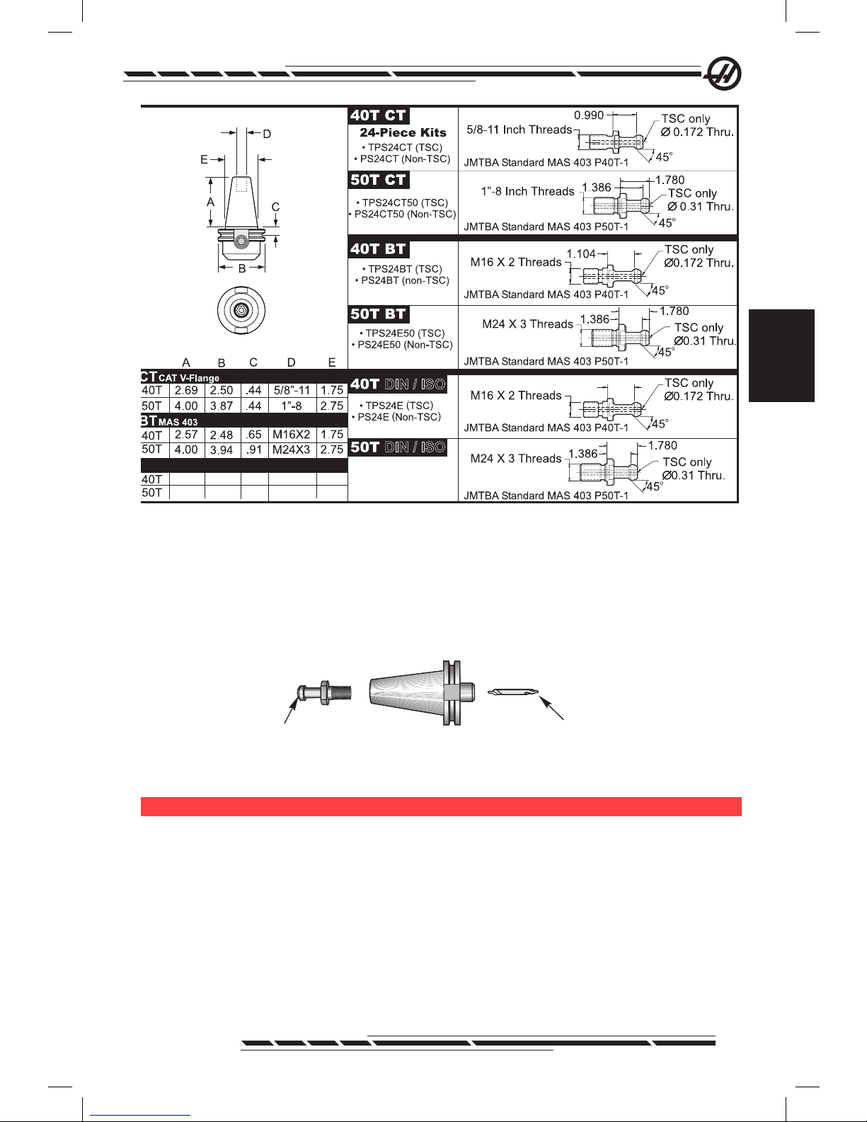
47
96-8000 Rev AC
May 2010
Operation
.
2.69 2.50
.44
M16X2
M24X3
1.75
4.00
3.84
.44
2.75
.990
DIN/ISO
DIN/ISO
Tool Holder Assembly
Tool holders and pull studs must be in good condition and tightened together
with wrenches or they may stick in the spindle. Clean the tool holder body (the
part that goes into the spindle) with a lightly oiled rag to leave a lm, which will
prevent rusting.
.
Tool (Center Drill)
40 Taper CT Tool Holder
Pull Stud
Install a tool into the tool holder as instructed by the tool manufacturer.
to o l ch a n G e r
There are two types of tool changers available for the Haas mills; these are the
side mount tool changer and the umbrella style. Both types are commanded in
the same manner, but each one is set up differently.
Before loading tools the mill must be zero returned (power up restart button),
which should have been done at machine power up.
The tool changer is manually operated using the tool release button and the
ATC FWD and ATC REV buttons. There are two tool release buttons; one on
the side of the spindle head cover and the second on the keypad.
Page 57

48
96-8000 Rev AC
May 2010
Loading the Tool Changer
CAUTION! Do not exceed the maximum tool changer specications. Extremely
heavy tool weights should be distributed evenly. This means heavy tools should
be located across from one another, not next to each other. Ensure there is
adequate clearance between tools in the tool changer; this distance is 3.6” for a
20-pocket.
NOTE: Low air pressure or insufcient volume will reduce the pressure
applied to the tool unclamp piston and will slow down tool change time or
will not release the tool.
CAUTION! Keep clear of the tool changer during power up, power down, and
any tool changer operations.
Tools are always loaded into the tool changer by rst installing the tool into the
spindle. Never load a tool directly into the tool changer.
CAUTION! Tools that make a loud bang when being released indicate a problem
and should be checked before serious damage to the tool changer occurs.
Tool Loading for a Side Mount Tool Changer
NOTE: A normal size tool has a diameter of less than 3” for 40-taper
machines, or less than 4” for 50-taper machines. Tools larger than these
measurements are considered large size.
1. Ensure the tools loaded have the correct pull stud type for the mill.
2. Press the CURNT COMDS button. From a fresh Power Up/Restart, press
the Page Up key once to reach the Tool Pocket Table display. From a normal
operating state, press Page Up/Down to reach the Tool Pocket Table.
3. Clear any current “Large” or “Heavy” tool designations. Use the cursor keys
to scroll to any tool pocket that has an “L” or “H” next to it. Press Space, then
Write/Enter to clear the “Large” or “Heavy” tool designations. Or press 3, then
Origin to clear all designation.
Page 58

49
96-8000 Rev AC
May 2010
Operation
.
1
2
Large (and heavy) tool with
surrounding pockets empty
Heavy Tool (not large)
4. Press Origin to reset the Tool Pocket Table to default values. This will place
tool 1 in the spindle, tool 2 in pocket 1, tool 3 in pocket 2, etc. This is done to
clear the previous Tool Pocket Table settings as well as renumber the Tool
Pocket Table for the next program. Another way to reset the Tool Pocket Table
is to enter 0 (zero) and press Origin, this will reset all the values to zero.
NOTE: There cannot be two different tool pockets holding the same tool
number. Entering a tool number already displayed in the Tool Pocket Table
will result in an “Invalid Number” error.
5. Determine if the next program will need any large tools. A large tool has a
diameter of greater than 3” for 40-taper machines and greater than 4” for 50taper machines. If large tools are not used, proceed to Step 10. If large tools
are used, proceed to the next step.
6. Organize the tools to match to the CNC program. Determine the numerical positions of large tools and designate those pockets as Large in the Tool
Pocket Table. To designate a tool pocket as “Large”, scroll to that pocket, press
L, then Write/Enter.
CAUTION! A large tool cannot be placed in the tool changer if one or both of the
surrounding pockets already contain tools. Doing so will cause the tool changer
to crash. Large tools must have the surrounding pockets empty. However, large
tools can share adjoining empty pockets.
7. When all necessary Large and Heavy tool pockets are designated, press
the Origin key to renumber the Tool Pocket Table. At this point, the machine is
ready to accept tool 1 into the spindle.
8. Take tool 1 in hand and insert the tool (pull stud rst) into the spindle. Turn
the tool so that the two cutouts in the tool holder line up with the tabs of the
spindle. Push the tool upward while pressing the Tool Release button. When
the tool is tted into the spindle, release the Tool Release button.
Page 59

50
96-8000 Rev AC
May 2010
.
Tool Release Button
9. Press the “Next tool” button.
10. Repeat Steps 9 and 10 until all the tools are loaded.
High-Speed Side Mount Tool Changer
The high-speed tool changer has an additional tool assignment, which is
“Heavy”. Heavy tools are dened as tools weighing more than 4 pounds. If a
tool, heavier than 4 pounds is used, the tool must be entered in the table with
an “H” (Note: All large tools are considered heavy). During operation an “h” in
the tool table denotes a heavy tool in a large pocket.
As a safety precaution, the tool changer will run at a maximum of 25% of
the normal speed if changing a heavy tool. The pocket up/down speed is not
slowed down. The control restores the speed to the current rapid, once the tool
change is complete. If problems are encountered changing unusual or extreme
tooling, contact your dealer for assistance.
H - Heavy, but not necessarily large (large tools require empty pockets on
either side).
L - Empty pockets are required on both sides (large tools are assumed heavy).
h - Heavy small diameter tool in a pocket designated for a large tool (must
have empty pocket on both sides). The lower case “h” and “l” is placed by the
control; never enter a lower case “h” or “l” into the tool table.
l - Small diameter tool in a pocket reserved for a large tool in the spindle.
Large tools are assumed to be heavy.
Heavy tools are not assumed to be large.
On non-high speed tool changers, “H” and “h” have no effect.
Page 60

51
96-8000 Rev AC
May 2010
Operation
Tool Loading Flowchart
.
Press POWER UP/RESTART
Wait for Zero Return
Any Large or Heavy
tool designations
displayed?
Remove Large and/or
Heavy tool
designations by
scrolling to each “L”
and/or “H” and
pressing SPACE,
WRITE. Remove all
by pressing 3,
ORIGIN.
Press ORIGIN.
Will you need any
Large or Heavy
tools?
Organize your tools
according to your CNC
program. Determine
numerical positions of
Large tools.
Do you have
additional largetools
to designate?
InsertTool into the
spindle.
Jog Z-Axisto set tool offset.
Press .TOOL OFFSET MESUR
Press .NEXT TOOL
Do you have additonal
toolstoload?
Loading the
Side Mount Tool
Changer
Press CURNT COMDS,
PAGE UP to view
theTool Pocket Table.
Y
N
Y
N
Scroll to the tool
pocket that will hold
a large tool and press
L, WRITE. (Or press H
foraheavy tool )
Y
N
Y
N
END
Press ORIGIN
(from PowerOn)
A “Large Tool” hasadiameter
greater than 3"
for 40-taper mills, or greater
than 4" for
50-taper mills.
High-speed Toolchangers: A
“Heavy Tool” isatool weighing
4ormore pounds.
Do not enter a lower case
“h” or lower case “l”(L) in
the tool table.
Press HAND JOG,
OFSET to display
Tool OffsetTable.
Page 61

52
96-8000 Rev AC
May 2010
Using 0 for a Tool Designation
A 0 (number zero) can be inserted in the tool table in place of a tool number.
If this is done the tool changer does not “see” this pocket and will never try to
install or retrieve a tool from pockets with a “0” designation.
Enter 0 then Origin to zero all pockets, enter 1 then Origin to sequence the
pockets, and enter a 3 then Origin to clear all H,h,L,l enteries. A 0 cannot be
used to designate the tool inserted into the spindle. The spindle must always
have a tool number designation.
To designate a pocket as an “always empty” pocket: Use the arrow keys to
move to and highlight the pocket to be empty, press the 0 button on the numeric keypad and then press Enter.
Moving Tools in the Carousel
Should tools need moving in the carousel, follow the steps below.
CAUTION! Plan the reorganization of the tools in the carousel ahead of time. To
reduce the potential for tool changer crashes, keep tool movement to a minimum.
If there are large or heavy tools currently in the tool changer, ensure that they are
only moved between tool pockets designated as such.
Creating Room for a Large Size Tool
The tool changer pictured has an assortment of normal size tools. For the purposes of this example, tool 12 will be moved to pocket 18 to create room for a
large size tool to be placed in pocket 12.
1. Select MDI mode. Press the CURNT COMDS button. Press Page Up/Down
(if necessary) to reach the Tool Pocket Table display. Verify which tool number
is in pocket 12.
2. Enter Tnn into the control (where Tnn is the tool number from step 1). Press
ATC FWD. This will place the tool from pocket 12 into the spindle.
3. Enter P18 into the control, then press ATC FWD to place the tool currently in
the spindle into pocket 18.
.
To ol 12 to Pocket 18
Large Tool
in Pocket 12
4. Scroll to pocket 12 in the Tool Pocket Table and press L, Write/Enter to designate that pocket as Large.
Page 62

53
96-8000 Rev AC
May 2010
Operation
5. Enter the tool number into SPNDL (spindle) on the Tool Pocket Table. Insert
the tool into the spindle.
NOTE: There cannot be two different tool pockets holding the same tool number. Entering a tool number already displayed in the Tool Pocket table will result
in an “Invalid Number” error.
6. Enter P12 into the control and press ATC FWD. The tool will be placed into
pocket 12.
NOTE: Extra large tools can be programmed as well. An “Extra large” tool is
one that takes up three pockets; the diameter of the tool will cover the tool
pocket on either side of the pocket it is installed in. Change bit 3 of parameter
315 to 1, if a tool this size is needed. The tool table must be updated as now
two empty pockets are needed between extra large tools.
Umbrella Tool Changer
Tool Loading Tools are loaded into the umbrella tool changer by rst loading the
tool into the spindle. To load a tool into the spindle, prepare the tool and then
follow these steps:
1. Ensure the tools loaded have the correct pull stud type for the mill.
2. Enter MDI mode.
3. Organize the tools to match to the CNC program.
4. Take tool 1 in hand and insert the tool (pull stud rst) into the spindle. Turn
the tool so that the two cutouts in the tool holder line up with the tabs of the
spindle. Push the tool upward while pressing the Tool Release button. When
the tool is tted into the spindle, release the Tool Release button.
5. Press the “ATC FWD” key.
6. Repeat Steps 4 and 5 with the remaining tools until all the tools are loaded.
Umbrella Tool Changer Recovery
If the tool changer jams, the control will automatically come to an alarm state.
To correct this, push the Emergency Stop button and remove the cause of the
jam. Push the RESET button to clear the alarms. Push the Recover button and
follow the directions to reset the tool changer.
CAUTION! Never put your hands near the tool changer unless the EMERGENCY
STOP button is pressed rst.
Side Mount Tool Changer Recovery
If a problem occurred during a tool change, a tool changer recovery needs to
be performed. Enter the tool changer recovery mode by pressing the Recover
button. Once in tool changer recovery mode, instructions are given and ques-
tions are asked to perform a proper tool changer recovery. The entire tool
changer recovery process must be completed before exiting. If the routine is
exited early the tool changer recovery must be started from the beginning.
Page 63

54
96-8000 Rev AC
May 2010
Side Mount Tool Changer Door and Switch Panel (if equipped)
Mills such as the MDC, EC-300 and EC-400 have a sub-panel to aid tool loading. The Manual/Auto switch must be set to “Auto” for automatic tool changer
operation. If the switch is set to “Manual”, the other two buttons, labeled CW
and CCW, are enabled and automatic tool changes are disabled. The CW and
CCW buttons rotate the tool changer in the clockwise and counterclockwise
directions. The door has a switch which detects when the door is open.
.
Rotate Tool Changer
Carousel CCW
Rotate Tool Changer
Carousel CW
Manual
Operation
Automatic
Operation
Tool Changer Door and Switch Panel Symbols
Operation
If the cage door is opened while a tool change is in progress, the tool change
will stop and not resume until the cage door is closed. However, any machining
operations that are in progress will continue.
If the switch is turned to “Manual” while a tool change is in progress, current
tool changer motion will be completed. The next tool change will not execute
until the switch is turned back to “Auto”. Any machining operations that are in
progress will continue.
The carousel will rotate one position whenever the CW or CCW button is
pressed once, while the switch is set to “Manual”
During tool changer recovery, if the cage door is open or the switch is in the
“Manual” position and the Recover button is pressed, a message is displayed
telling the operator the door is open or is in manual mode. The operator must
close the door and set the switch to the automatic position in order to continue.
Page 64

55
96-8000 Rev AC
May 2010
Operation
Side Mount Tool Changer Recovery Flow Chart
.
Press Recover
Button
Alarms
exist?
Y
Tool in
armor spindle
(Y/N)?
Will arm
prevent tool in
spindle or pocket
from being
removed
(Y/N)?
Y
Y
N
Use following commands to remove all tools from
spindle and arm. Move carousel with arrows.
ATC Rev-Rotate arm
Tool Release -Toggle tool un/clamp
Up/Down arrow-Moves Pkt up or down
Orient Spindle-Spindle orientation
To move spindle up/down, arm must be at origin,
and you must exit tool changer recovery.
Are you finished using commands (Y)?
CNC waits for ‘Y’ before continuing.
Orient
spindle
pressed?
N
Use Tool Release button while holding tool
and remove alltoolsfrom arm and spindle.
Depress tool-clamp-release stud on arm while
holding tool and slidetool out. Notea
tool-clamp-release stud for each end of arm
Are allthe toolsremoved (Y)?
Cnc waits for‘Y’ before continuing
Y
About to orient spindle.
Caution! This may
damage tool arm if
spindle interferes with
itsmotion. Press ‘O’ to
orient, ‘N’to cancel.
N
Alarms exist, they must be cleared.
Press ‘Y’to continue, then ‘Reset’
to clear alarms, then retry.
N
Armat
origin?
Y
N
‘N’or‘O’
Orient spindle
N
O
Y
At origin,
continue to Pkt
Restore (Y)?
Cnc waits for‘Y’
before
continuing
Carousel
between
pockets?
Y
N
Restoring pockets,
please wait
Check current
carousel
pocket, enter
current pocket
number, and
press 'Enter'.
Use AT C Fwd/Rev to rotate arm to origin
Press arrow key
to move carousel
or ‘Write’to
continue
automatic
recovery
Cnc waits for
’Write’ before
continuing
Move to next
pocket
N
Tool change
recovery complete!
Press ‘Y’to
continue. Please
update pocket and
tool page.
Offset page with
pockets displayed.
Tool may fall during tool recovery. Place
something soft under tool to catch it. Don't
use hands to catch tool, and press ‘Y’to
continue. CNC waits for ‘Y’ before continuing.
END
Arm at
origin?
Carousel
between
pockets?
Y
N
Sensorsand Diagnostic Logic
Cam Box
Carousel Chart
Signal Origin Rotation Tool
Stow Pick-up
Drop-off
Clamp/Unclamp Amber/0 Amber/0 Off/1
Origin Off/1 Red/0 Red/0
Motor Stop Off/1 Red/0 Off/1
Signal Pocket Pocket Pocket Pocket Pocket
Tool one Tool in Up Down Between
In Position Position Up&Down
(Pocket) Tool one in pos. 0 1111
(Pocket) Tool in Position 0 000
Discrete Input
Discrete Input
0
Pocket Up 0 0011
Pocket Down 1 1101
Hydraulic Tool Changer
Tool Pocket Setup
The Tool pocket table is accessed by pressing the Offset key and then press
the right cursor arrow key to reach the tool pocket column. Enter the pocket
values for each tool used. This table must be properly setup by the operator to
avoid the possibility of damaging tools, the spindle or the tool changer.
Creating a New Tool Table
During the course of operating the machining center it will be necessary to
completely reprogram the tool table. There are two useful functions that can be
used as an aid in creating a new tool table:
Pressing the ‘ORIGIN’ button on the keypad at any time while on the tool table
screen will set all the tool pockets to their default values. For example, tool 1 in
the spindle, tool 2 in pocket 1, tool 3 in pocket 2, etc.
Page 65

56
96-8000 Rev AC
May 2010
Pressing ‘0’ and then the ‘ORIGIN’ button on the keypad at any time while on
the tool table screen will set all the tool pockets to ‘0’.
Tool Numbering System
Powering up the machine for the rst time sets the default tool-pocket table.
The table is setup such that each pocket contains a tool with the same number as the pocket number. The spindle is initialized to contain Tool 1 (T1). For
example, Pocket 1 is dedicated to contain Tool 1 (T1), Pocket 2 is dedicated to
Tool 2 (T2), etc. Therefore, the ATC 38 side-mount tool changer has a default
of 38 tools, T1 through T38 (T1 in the spindle).
The tool numbers in the tool table assigns a dedicated tool number to each
pocket of the tool changer. This number remains in the tool table regardless of
where the tool actually is. For example, if tool 5 (T5) is removed from the tool
pocket 5 and placed in the spindle, the tool table will indicate that T5 is in the
spindle and that pocket 5 is dedicated to tool T5.
A tool called for from the machine’s program commands the control to search
the tool table for the tool number and indexes the tool changer to the pocket
containing the tool number.
CAUTION! Damage to the machine and/or tooling can occur if the tool called for in
the program does not match the tool listed in the tool table and/or installed in the
corresponding pocket.
Acceptable Tool Numbers
In general the tool numbers are from T1 to the number of pockets in the tool
changer chain (T38 on a 30-pocket tool changer, however, it is possible to use
all the numbers in the tool table. This is done to allow for a situation where the
operator requires more than available tool pockets to complete the machining
job. An example is 55 different tools are required to perform a complete machining job. The rst 38 tools would be used and then the machine would be
paused while the operator removes 17 of the original tools and replaces them
with the 17 tools required to complete the job. After updating the tool table to
reect the new tools in their respective pockets using tool numbers T39 through
T55 the machining job is ready to continue.
Using ‘0’ for a Tool Designation
A tool pocket can be labeled as an “always empty” pocket, by entering “0”
(zero) for the tool number in the tool table. If this is done the tool changer does
not “see” this pocket and will never try to install or retrieve a tool from pockets
with a ‘0’ designation.
A zero cannot be used to designate the tool inserted into the spindle. The
spindle must always have a tool number designation.
Use of “Large ” Tool Designations
The tool changer can accept oversized tools as long as the adjacent pockets
Page 66

57
96-8000 Rev AC
May 2010
Operation
are left empty and a designator is added to the tool table. Oversize (large)
tools are tools with a diameter of more than 4.9” (125mm).
To designate a large tool, scroll to highlight the specic pocket (the one that
holds the large tool) and press “L” and then the ‘WRITE/ENTER’ button. The
letter “L” will appear on the screen next to this pocket and the tool numbers on
either side will be changed to “-“ indicating that tools cannot be inserted into
these pockets.
To remove an ‘L’ designation, highlight the ‘L’ pocket and press the ‘SPACE’
button and then the ‘WRITE/ENTER’ button.
NOTE: Large tools cannot be bigger than 9.8” (250mm).
Heavy tools
Designating a tool as “Heavy” will have no affect on tool changer speed or actions.
Installing/Removing Tools (hydraulic tool changer)
Tools can be installed into the tool changer by inserting them directly into the
pockets or by installing them into the spindle and using the ATC FWD/REV
buttons on the keypad to stow the tools in the tool changer. During initial setup,
using the ATC FWD/REV buttons, the rst tool inserted into the spindle will be
tool T1 and will be placed into pocket 1.
To install them directly in the tool changer chain, turn switch on the operator’s
sub-panel to “Manual”, open the operator door (it is at the back of the tool
changer cage), and install the tool in the chain. Use the CW/CCW buttons to
move the chain to the next empty pocket. Remember to leave an empty pocket
on either side of a large tool.
Update the tool changer tool table once all the tools are installed.
Tools can be removed, by calling each tool to the spindle and removing them
from it, or by taking them directly from the chain at the operator station in the
tool cage. To remove tools from the chain, turn the switch to “Manual”, open the
tool-cage operator door, grasp the tool and press the foot pedal.
ATC FWD, ATC REV Operation (hydraulic tool changer)
Using ATC FWD/REV will cause the tool changer to move to the next tool
pocket with respect to the tool in the spindle. For example, if tool T15 is in the
spindle and it is dedicated to pocket 20, the tool changer will put tool T15 into
pocket 20 and then ATC FORWARD to pocket 21. It will not retrieve tool 16
(T16).
The ATC FWD/REV buttons will change the tool, in the spindle, to the next or
previous tool. However, if the next, or previous, tool is a pocket designated with
a zero (an empty pocket) the tool changer will skip that pocket and get a tool
from a non-zero pocket.
Page 67

58
96-8000 Rev AC
May 2010
Tool Changer Recovery (hydraulic tool changer)
The tool changer recovery mode is used to manually move the tool changer’s
arm and carriage into its HOME position.
Press the “Recover” button and follow the on-screen prompts to return the tool
changer to the home position.
St i c K i n G t o o l S
Tools may stick in the spindle when a cold tool is put in a hot spindle. To remove a stuck tool:
Let the spindle cool, and try removing the tool with the Tool Release button.
If the tool is still stuck see below.
Note: Two people are necessary to remove a stuck tool from the spindle
Warning: Wear gloves and eye protection as tools are sharp and can
shatter
Hold the tool with one hand and tap the tool holder (not the spindle) with a
piece of aluminum or brass. A small plastic mallet can be used if the other
pieces are not available. The other person will press and hold the Tool Release
button.
Jo G Mo d e
Jog Mode allows each axes to be jogged to a desired location. Before jogging
the axes it is necessary to home (beginning axes reference point) the axes
(See the Machine Power-up Section).
To enter jog mode press the hand jog button, then press one of the desired
axes (e.g. X, Y, Z, A or B etc.) and either use the handle jog buttons or the jog
handle to move the axes. There are different increment speeds that can be
used while in jog mode; they are .0001, .001, .01 and .1. The optional Remote
Jog Handle (RJH) can also be used to jog the axes.
Se t t i n G of f S e t S
In order to accurately machine a work piece, the mill needs to know where the
part is located on the table. Jog the mill with a pointer tool in the spindle, until it
reaches the top left corner of the part (see the following illustration); this posi-
tion is part zero. The values will be entered into G54 on the Work Offset page.
Offsets can also be entered manually by choosing one of the offsets pages,
moving the cursor to the desired column, typing a number and pressing Write
or F1. Pressing F1 will enter the number in the selected column. Entering a
value and pressing Write will add the amount entered to the number in the
Page 68

59
96-8000 Rev AC
May 2010
Operation
selected column.
ty P i c a l Wo r K of f S e t Se t -U P
1. Place the material in the vise and tighten.
2. Load a pointer tool in the spindle .
3. Press Handle Jog (A).
4. Press .1/100. (B) (The mill will move at a fast speed when the handle is
turned).
5. Press +Z (C).
6. Handle jog (D) the Z-axis approximately. 1” above the part.
7. Press .001/1. (E) (The mill will move at a slow speed when the handle is
turned).
8. Handle jog (D) the Z-axis approximately. 0.2” above the part.
9. Select between the X and Y axes (F) and handle jog (D) the tool to the upper
left corner of the part (See the following illustration).
10. Press Offset (G) until the Work Zero Offset Pane is active.
11. Cursor (I) to G54 Column X.
12. Press Part Zero Set (J) to load the value into the X-axis column. The second press of Part Zero Set (J) will load the value into the Y-axis column.
CAUTION! aDo Not Press Part Zero Set a third time; doing so will load a value into
the Z-axis. This will cause a crash or Z-axis alarm when the program is run.
.
Spindle at top leftof the front
A
D
F
H
B
EI
C G
J
Setting the Tool Offset
The next step is to touch off the tools. This denes the distance from the tip of
the tool to the top of the part. Another name for this is Tool Length Offset, which
is designated as H in a line of machine code; the distance for each tool is en-
tered into the Tool Offset Table.
Page 69

60
96-8000 Rev AC
May 2010
1. Load the tool in the spindle.
2. Press Handle Jog (A).
3. Press .1/100. (B) (The mill will move at a fast rate when the handle is
turned).
4. Select between the X and Y axes (C) and handle jog (D) the tool near the
center of the part.
5. Press +Z (E).
6. Handle jog (D) the Z axis approximately 1” above the part.
7. Press .0001/.1 (F) (The mill will move at a slow rate when the handle is
turned).
8. Place a sheet of paper between the tool and the work piece. Carefully move
the tool down to the top of the part, as close as possible, and still be able to
move the paper.
9. Press Ofset (G).
10. Press Page Up (H) until the page with “Coolant - Length - Radius at the top
and scroll to tool #1.
11. Cursor (I) to Geometry for position #1.
12. Press Tool Ofset Mesur (J).
This will take the Z position located in the bottom left of the screen and put it at
the tool number position.
CAUTION! The next step will cause the spindle to move rapidly in the Z axis.
.
B
FD
I
K
C
HEJ G
A
Tool Length
is measured
from the tip
of thetool
to thetop of
thepartwith
theZaxis at
its home
position.
TipofTool
Topof Part
13. Press Next Tool (K).
Additional Tooling Set-up
There are other tool set-up pages within the Current Commands. Press Curnt
Comds and then use the Page Up/Down buttons to scroll to these pages.
The rst is the page with “Spindle Load” and “Vibration” at the top of the page.
The programmer can add a tool load limit for spindle load and vibration. The
control will reference these values and can be set to do a specic action should
Page 70

61
96-8000 Rev AC
May 2010
Operation
the limitations be reached (See setting 84).
The second page is the Tool Life page. On this page there is a column called
“Alarm”. The programmer can put a value in this column, causing the machine
to stop once the tool has been used that amount of times.
Tool Management Introduction
Advanced Tool Management (ATM) allows the programmer to setup and access duplicate tools for the same or a series of jobs. The ATM page is located
in the Current Commands mode (Press Current Commands button and page
up once). A sample of the ATM screen follows; the screen has “TOOL GROUP”
in the title.
Duplicate or backup tools are classied into specic groups. The programmer
species a group of tools instead of a single tool in the G-code program. ATM
will track the usage of individual tools in each tool group and compare it to user
dened limits. Once a limit (e.g. number of times used, or tool load) has been
reached the mill will automatically choose one of the other tools in the group
the next time that tool is needed.
To activate ATM, make sure that Setting 7 (Parameter lock) is off and press Estop. Under Parameter 315, bit 28, change the value from “0” to “1” and press
F4 to switch between windows. Use the cursor keys (left, right, up, down) to
move to different items inside the active window. Pressing the Enter key will
select, modify or clear values in each item depending on the selection.
The bottom left corner displays simple help information for selected items.
ad v a n c e d to o l Ma n a G e M e n t oP e r a t i o n
.
<NEXT> <ADD> <DELETE>
DESCRIPTION:
IN ORDER
FEED TIME:
HOLES:
TL IN SPINDLE1
TOOLSEXP LIFE
0
0
0
0
0
0
CRNT PKT
ADVANCED TOOL MANAGEMENT
PRESSF4TOCHANGEACTIVE WINDOW
Allowed LimitsWindow
Tool Data Window
Help Text
Tool Group Window
ActiveWindowLabel
Press WRITE/ENTERtodisplay
the previoustool groups data
<PREVIOUS>
GROUP ID:
GROUPUSAGE:
<RENAME>
1000
<SEARCH>
TL ACTION:ALARM
TOTALT IME:
TOOL LOAD:
USAGE:
0
0
0
0
0
HOLES
0
FEED TIME
TOTALTIME
H-CODE D-CODE FLUTES
USAGE LOAD
(TOOL DATA)
Tool Group - In the Tool Group Window the operator denes the tool groups
used in the programs.
Previous – Highlighting <PREVIOUS> and pressing Enter changes the display
Page 71

62
96-8000 Rev AC
May 2010
to the previous group.
Next – Highlighting <NEXT> and pressing Enter changes the display to next
group.
Add – Highlight <ADD>, enter a number between 1000 and 2999, and press
Enter to add a tool group.
Delete – Use <PREVIOUS> or <NEXT> to scroll to the group to delete.
Highlight <DELETE> and press Enter. Conrm the deletion; answering ‘Y’ will
complete the deletion; answering ‘N’ will cancel the deletion.
Rename - Highlight <RENAME>, enter a number 1000 and 2999 and press
enter to renumber the group ID.
Search - To search for a group, highlight <SEARCH>, enter a group number
and press enter.
Group Id – Displays the group ID number.
Group Usage – Enter the order in which the tools in the group are called. Use
the left and right cursor keys to select how the tools are used.
Description – Enter a descriptive name of the tool group.
Allowed Limits - The Allowed Limits window contains the user dened limits
to determine when a tool is worn out. These variables affect every tool in the
group. Leaving any variable set to zero causes them to be ignored.
Feed Time – Enter the total amount of time, in minutes, a tool is used in a feed.
Total Time – Enter the total time, in minutes, a tool is used.
Tool Usage – Enter the total times a tool is used (number of tool changes).
Holes – Enter the total number of holes a tool is allowed to drill.
Tool Load – Enter the maximum tool load (in percent ) for the tools in the
group.
TL Action* – Enter the automatic action to be taken when the maximum tool
load percentage is reached. Use the left and right cursor keys to select the
automatic action.
Tool Data
TL in Spindle – Tool in the spindle.
Tool – Used to add or remove a tool from a group. To add a tool press F4 until
the Tool Data window is outlined. Use the cursor keys to highlight any of the
areas under the “Tool” heading and enter a tool number. Entering zero will clear
the tool or highlighting the tool number and pressing ORIGIN will reset the HCode, D-Code and Flutes data to the default values.
Page 72

63
96-8000 Rev AC
May 2010
Operation
EXP (Expire) – Used to manually obsolete a tool in the group. To obsolete a
tool, enter a ‘*’, or to clear an obsolete tool, ( * ), press enter.
Life – The percentage of life left in a tool. This is calculated by the CNC con-
trol, using actual tool data and the limits the operator entered for the group.
CRNT PKT – The tool changer pocket the highlighted tool is in.
H-Code – The H-code (tool length) that will be used for the tool. H-code cannot
be edited unless Setting 15 H & T Code Agreement is set to Off. The operator
can change the H-code by entering a number and pressing Enter. The number
entered will correspond to the tool number in the tool offsets display.
D-Code – The D-code that will be used for that tool. D-code can be changed by
entering a number and pressing Enter.
NOTE: By default the H and D-codes in Advanced Tool Management are
set to equal the tool number that is added to the group.
Flutes – The number of utes on the tool. This can be edited by selecting it,
entering a new number, and pressing Enter. This is the same as the “Flutes”
column listed on the tool offsets page.
Highlighting any of the following sections (Holes through Load) and pressing
ORIGIN will clear their values. To change the values, highlight the value in the
specic category, enter a new number and press enter.
Load – The maximum load, in percent, exerted on the tool.
Holes – The number of holes the tool has drilled/ tapped/ bored using Group 9
canned cycles .
Feed Time – The amount of time, in minutes , the tool has been in a feed.
Total Time – The total amount of time, in minutes, the tool has been used.
Usage – The number of times the tool has been used.
Tool Group Setup
To add a tool group press F4 until the Tool Group window is outlined. Use the
cursor keys until <ADD> is highlighted. Enter a number between 1000 and
2999 (this will be the group ID number). To change a group ID number, highlight the <RENAME> feature, enter a new number and press enter.
Tool Group Usage
A tool group must be setup prior to using a program. To use a tool group in a
program rst set up a tool group. Next, substitute the tool group ID number for
the tool number and for the H-codes and D-codes in the program. See the fol-
lowing program for an example of the new programming format.
Example:
Page 73

64
96-8000 Rev AC
May 2010
T1000 M06 (tool group 1000)
G00 G90 G55 X0.565 Y-1.875 S2500 M03
G43 H1000 Z0.1 (H-code 1000 same as group ID number)
G83 Z-0.62 F15. R0.1 Q0.175
X1.115 Y-2.75
X3.365 Y-2.875
G00 G80 Z1.0
T2000 M06 (use tool group 2000)
G00 G90 G56 X0.565 Y-1.875 S2500 M03
G43 H2000 Z0.1 (H-code 2000 same as group ID number)
G83 Z-0.62 F15. R0.1 Q0.175
X1.115 Y-2.75
X3.365 Y-2.875
G00 G80 Z1.0
M30
Macros
Tool Management can use macros to obsolete a tool within a tool group.
Macros 8001 to 8200 represents tool 1 through 200. By setting one of these
macros to 1, the operator can expire a tool.
Example:
#8001 = 1 (this will expire tool 1 and it will no longer be used )
#8001 = 0 (if tool 1 was expired manually or with a macro, then
setting macro 8001 to 0 will make tool 1 available again for use)
Macro variables 8500-8515 enable a G code program to obtain tool group
information. When a tool group ID number is specied using macro 8500, the
control will return the tool group information in macro variables 8501 through
8515.
See the variables 8500-8515 in the Macros chapter for the macro variable data
label information.
Save and Restore Advanced Tool Management tables
The control can save and restore the variables associated with the Advanced
Tool Management (ATM) feature to oppy disk and RS-232. These variables
hold the data that is entered on the ATM screen. The information can be saved,
either as part of an overall backup by using the LIST PROG/POSIT page, or
save only the ATM information by bringing up the ATM display screen and
pressing F2. When the Advanced Tool Management data is saved as part of an
overall backup, the system creates a separate le with a .ATM extension. The
ATM data can be saved and restored via the RS232 port by pressing the SENDRS232 and RECV232 buttons while the Advanced Tool Management screen
is displayed.
Page 74
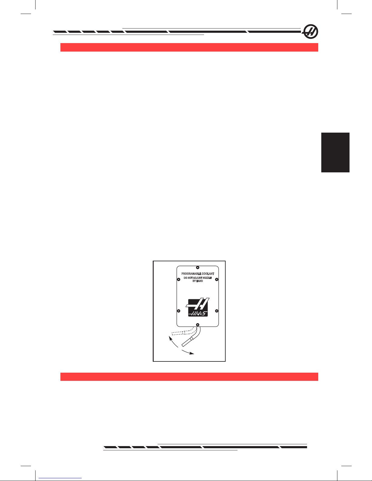
65
96-8000 Rev AC
May 2010
Operation
oP t i o n a l Pr o G r a M M a b l e co o l a n t SP i G o t
The optional programmable coolant (P-cool) directs coolant at the work piece
at various angles. The angle of the coolant can be changed within the CNC
program.
An additional column on the tool offset page titled “Coolant Position” is dis-
played, with htis option. The spigot will be moved to the position entered for
the specic tool when the associated H code and M08 is called.
Programmable Coolant (P-Cool) Set-up
1. Press the OFFSET button to enter the offsets table, press the CLNT UP or
CLNT DOWN button to move the P-cool nozzle into the desired position. Press
the COOLNT button to turn on the coolant in order to check the P-cool position.
Note: The P-cool position is displayed at the bottom left corner of the screen.
2. Enter the coolant position number for the tool in the Coolant Position column
and press F1. Repeat steps 1 and 2 for each tool.
3. Enter the coolant position as an H code in the program. For example H2
will command the nozzle to the position entered in the Tool 2 Coolant Position
column.
If setting 15 (H & T Agreement) is on the H code and T code commanded in the
program must be the same (e.g. T1 H1 must be used together). If setting 15 is
turned off the H code and T code commanded do not need to be the same (e.g.
T1 H2 can be commanded).
.
PROGRAMABLE COOLANT
DO NOT ADJUST NOZZLE
BY HAND
Home
H01
H20
Gr a P h i c S Mo d e
A safe way to troubleshoot a program is to run it in Graphics mode. No movement will occur on the machine, instead the movement will be illustrated on the
screen.
Graphics mode can be run from Memory, MDI, DNC or Edit modes. To run
a program press the SETNG/GRAPH button until the Graphics page is dis-
Page 75

66
96-8000 Rev AC
May 2010
played. Or press Cycle Start from the active program pane in Edit mode to
enter Graphics mode. To run DNC in graphics, select DNC, then go to graphics
display and send the program to the machine’s control (See the DNC section). There are three helpful display features in Graphics mode that can be
accessed by pressing one of the function keys (F1 - F4). F1 is the help button,
which will give a short description of each of the functions possible in Graphics
mode. F2 is the zoom button, which highlights an area using the arrow buttons,
Page Up and Page Down to control the zoom level, and pressing the Write
button. F3 and F4 are used to control the simulation speed. Note that not all
machine functions or motions are simulated in graphics.
dr y rU n oP e r a t i o n
The Dry Run function is used to check a program quickly without actually cutting parts. Dry Run is selected by pressing the Dry Run button while in MEM or
MDI mode. When in Dry Run, all rapids and feeds are run at the speed select-
ed with the jog speed buttons.
Dry Run can only be turned on or off when a program has completely nished
or the Reset button is pressed. Dry Run will still make all of the commanded
XYZ moves and requested tool changes. The override keys can be used to adjust the Spindle speeds in Dry Run. Note: Graphics mode is just as useful and
may be safer as it does not move the axes of the machine before the program
is checked.
rU n n i n G Pr o G r a M S
Once a program is loaded on the machine and the offsets are set, run the pro-
gram by pressing the Cycle Start button. It is suggested that the program is run
in Graphics mode before doing any cutting.
ba c K G r o U n d ed i t
Background Edit will allows editing of one program while another program is
running. To activate Background Edit while a program is running, press Edit
until the background edit pane (on the right side of the screen) is active. Press
Select Prog to select a program to background edit (the program must be in
Memory) from the list and press Write/Enter to begin background editing. To
select a different program to background edit, press Select Prog from the back-
ground edit pane and choose a new program from the list.
All of the changes made during Background Edit will not affect the running
program, or its subprograms. The changes will go into affect the next time the
program is run. To exit background edit and return to the running program,
press Prgrm Convrs.
The Cycle Start button may not be used while in Background Edit. If the program contains a programmed stop (M00 or M30) exit Background Edit (press
Page 76

67
96-8000 Rev AC
May 2010
Operation
F4) and then press Cycle Start to resume the program.
Note: All keyboard data is diverted to the Background Editor, when a M109
command is active and Background Edit is entered, Once an edit is com-
plete (by pressing Prgrm/Convrs) keyboard input will return to the M109 in
the running program.
rU n -St o P -Jo G -co n t i n U e
This feature allows the operator to stop a running program, jog away from the
part, and then resume program execution. The following is an operation proce-
dure:
1. Press Feed Hold to stop the running program
2. Press X, Y or Z followed by the Handle Jog button. The control will store
the current X, Y, and Z positions. Note: Axes other than X, Y, and Z cannot be
jogged.
3. The control will display the message “Jog Away”. Use the jog handle, remote
jog handle, jog, or jog-lock buttons to move the tool away from part. Control
buttons such as AUX CLNT (TSC), or COOLNT to turn on/off the coolant (AUX
CLNT requires that the spindle is rotating and the door is closed). The spindle
can be controlled by pressing CW, CCW, Stop, Tool Release. If necessary, tool
inserts can be changed. Caution: When the program is continued, the old offsets will be used for the return position. Therefore, it is unsafe and not recommended to change tools and offsets when the program is interrupted.
4. Jog to a position as close as possible to the stored position, or to a position
where there will be an unobstructed rapid path back to the stored position.
5. Return to the previous mode by pressing MEM, MDI, or DNC. The control
will only continue if the mode that was in effect when stopped is re-entered.
6. Press Cycle Start. The control will display the message Jog Return and rapid
X and Y at 5% to the position where Feed Hold was pressed, then return the
Z-axis. Caution: The control will not follow the path used to jog away. If Feed
Hold is pressed during this motion, the mill axes motion will pause and display
the message “Jog Return Hold”. Pressing Cycle Start will cause the control to
resume the Jog Return motion. When the motion is completed, the control will
again go into a feed hold state.
7. Press Cycle Start again and the program resumes normal operation. Also
see Setting 36 Program Restart.
ax i S ov e r l o a d ti M e r
When a spindle or an axes current load is overloaded, a timer will start and
display POSITION pane. The starts at 1.5 minutes and counts down to zero. An
axis overload alarm (SERVO OVERLOAD) displays when the time has expired
Page 77

68
96-8000 Rev AC
May 2010
to zero.
Pa l l e t ch a n G e r (ec-Se r i e S a n d Mdc-500)
Introduction
The pallet changer is commanded through a CNC program. The M50 (execute
pallet change) function consists of unlocking, lifting and rotating the pallets,
then lowering and locking the pallets again. The pallet changer rotates the pallets 180o, then back; it does not continuously rotate in the same direction.
The pallet changer is provided with an audible signaling device to alert nearby
personnel when a pallet change is taking place. However, do not depend on
the signal to avoid mishaps.
Pallet Changer Warnings and Cautions
• Large workpieces may collide into frame during a pallet change.
• Verify tool length clearance during pallet changes. Long tools may collide
with workpiece.
.
Plane3
Items Beyond the Maximum
Radius and Height Limits
Will Damage the Machine
When the Pallet Rotates
EC-300 Shown
Maximum Pallet Loads
EC-300 550lb (249kg) per station, balanced within 20%
MDC 700lb (318kg) per station, balanced within 20%
EC-400 1 and 45 degree indexer – 1000 lb per pallet
Full 4th Axis 660 lb per pallet
Pallet Changer Operation
The Pallet Changer is commanded using M Codes. M50 determines if a pallet
has been scheduled. The pallets will change if a pallet is scheduled or the pro-
gram will pause and prompt the operator the pallet is not scheduled.
G188 uses the pallet schedule table to load and run the program scheduled for
the current pallet. Once the part program completes, the M99 command loops
back to the M50 (pallet change) in order to load the next pallet.
M36 is not used in this method, as M50 monitors the pallet scheduling. M36
is provided for backward compatibility, and to program pallet changes without
Page 78

69
96-8000 Rev AC
May 2010
Operation
using PST.
Messages aid the operator with loading/unloading and pallet changes. For
example, at the beginning of the M50 pallet change, if the load station is not
ready, a message is displayed on the screen. The message will not stop ash-
ing and the pallet change will not continue until the load station is ready and
the Part Ready button is pressed. At the beginning of a pallet change, if the
load station is ready, no messages appears, and no button press is required,
and the pallet change starts directly.
M46 – Qn Pmm
Jump to line mm in the current program if pallet n is loaded, otherwise go to the
next block.
M48 – Validate that current program is appropriate for loaded pallet
Checks in the Pallet Schedule Table that the current program is assigned to the
loaded pallet. If the current program is not in the list or the loaded pallet is incorrect for the program, an alarm is generated. M48 can be in a program listed
in the PST, but never in a subroutine of the PST program. An alarm will occur if
M48 is incorrectly nested.
M49Pnn Qmm – Sets the status of pallet nn to a value of mm.
Without a P-code, this command sets the status of the currently loaded pallet.
The status of each pallet are dened in the pull-down menu of the (PST).
Operator Load Station (EC-300, EC-400, MDC)
To ease loading/unloading parts and to speed production pallet changing mills
have an additional load area. The load station is guarded by a door, and a sub-
panel includes a few buttons to control the pallet changer. As a safety precaution the load station door must be closed before a pallet change can occur.
NOTE: The load station pallet must be at home to do a pallet change.
Page 79

70
96-8000 Rev AC
May 2010
Sub-Panel Controls
Emergency Stop: The button behaves just like the one on the operator’s pendant.
Rotary Index: Rotates the load station pallet (see Setting 164).
Part Ready: Used to indicate the pallet is ready. It also contains a light that 1)
blinks when the control is waiting for the operator or 2) is on when the operator
is ready for a pallet change.
Pallet Rotate Pallet Ready
Pallet Changer Sub-Panel Symbols
Pallet Changer G-Code
G188 Get Program From PST
Calls the parts program for the loaded pallet based on the PST entry for the
pallet
Pallet Changer Programming
The Pallet Changer can be programmed to run the same parts program on
both pallets, or a different program on each pallet. See “Sample Programs” for
some of the options available for pallet change programming.
Method 1 The following is the preferable method to accomplish a pallet
change:
To perform automatic pallet sequencing and part program selection, each pallet
must be “scheduled” and must have a part program assigned to it. Scheduling
is done in two ways, the rst is a pallet can be scheduled with the Part Ready
button on the operator’s panel. Pushing the button schedules the pallet that is
outside of the machining area.
The second is the pallets can be scheduled from the Pallet Schedule Table
(PST). This display can be found by pressing the CURNT COMDS key and
then pressing the Page Up or Page Down keys until the Pallet Schedule Table
page is reached. Use the arrow keys to highlight the “Load Order” box for the
pallet. Enter a pallet number and then the Write/Enter key. If there is already a
priority number for that pallet, the “Load Order” numbers of the other pallets will
be updated as necessary. A pallet that is on the receiver (in the work area) will
have an asterisk in the “Load Order” column; this pallet cannot be scheduled.
Assigning a part program is also done in the PST display. The arrow keys are
used to highlight the “Program Number” box for the pallet. The program num-
Page 80

71
96-8000 Rev AC
May 2010
Operation
ber is entered by keying the number and then pressing the Write/Enter key.
For example, keying “O123”, then Write/Enter will put the program number
O00123 into the table.
If a parts program encounters an M50 (without a P code) and the Part Ready
button has not been pressed, the control will pause operation, the beacon will
blink green, and the message “None Scheduled” is displayed. The mill will wait
until the Part Ready button has been pressed, or the PST has been updated,
before performing the pallet change. This feature prevents a pallet change from
occurring before the operator is ready. The Part Ready button can be pressed
at any time and will be recognized when the next pallet change is required.
Method 2
Although the previous method is recommended, the pallet changer can also be
operated without automatic sequencing or PST inputs. This is done using M50
with a P code. For proper operation M50 must be preceded by M36. M36 P1
before the M50 P1 will check that pallet #1 is ready.
Pallets can be changed without automatic sequencing or PST inputs. This is
done using M50 with a P code. M50 P1 will load pallet #1 without checking
to see if it is scheduled. If the PART READY button has been pressed, then
pallet #1 will be loaded. If the PART READY button for pallet #1 has not been
pressed, the indicator light on the button will ash and the message, “Schedule
Pal#1” is displayed.
Pallet Schedule Table
The pallet schedule table incorporates a number of features to help the user
with their routine.
Load Order and Pallet Status These two features work together to show
which pallet is currently in the machining area.
Pallet Usage This feature gives the number of times the specic pallet has
been loaded into the machining area. The counter will turn over to 0 after
32767 pallet changes.
Program Number This detail shows which program number has been as-
signed to the pallet.
Program Comment This area displays the comments that are written in the
part program.
There are 30 different pallet status values to use. The rst four: Unscheduled,
Scheduled, Loaded, and Completed, are xed and cannot be changed. The
remaining 26 can be modied and used as needed.
Changing or adding status text can be done in the PST. Use the arrow keys to
move the cursor to the “Pallet Status” column, and press the F1 key. A selection menu will appear over the “Pallet Status” column (Pressing F1 again or
Reset will close the menu.) The number to the left of the text is the status number. This number is used with the M49 command to set the status from the part
Page 81

72
96-8000 Rev AC
May 2010
program. The items in the menu can be selected with the Up and Down arrow
keys, or the jog handle. Enter the text, then press F3. Note: All pallets use the
same list of status items. Pressing F1 closes the menu without changing the
status of any of the pallets.
Resetting a status item to “User” is done by selecting an item from the menu
and pressing F4. All status items can be reset at the same time with the Origin
key.
Changing the status of an individual pallet can be done from the PST or with
the M49 command. In the PST, move the table cursor to the “Pallet Status”
column for the pallet desired. Press F1 for the status item menu. Use the arrow keys to select the status, then press F2 or Write/Enter. See the previous
description of M49 and in the following examples for setting the pallet status
from a program.
CAUTION! The following commands can cause either rotary products to move:
Zero Return or Handle Jog
.
Load
Area
Machining
Area
M48 must be placed at the beginning of the program (or section of program)
that is run for the current pallet. This will check each time that a program is run,
that the program matches the pallet. For example:
Oxxxx (Users program)
M48
;
; (Users part program for pallet 1)
;
M30
Oxxxx (Users program)
M48
;
; (Users part program for pallet 2)
;
M30
An alarm will be generated, “A (or B) not in Position”, if the pallet in the machine is not the one associated with the part program. If this alarm is generated, verify the correct program is running for the loaded pallet.
Page 82

73
96-8000 Rev AC
May 2010
Operation
Important: Verify that the rotary table on pallet one is plugged into “Connector
1”, and that the rotary table on pallet two is plugged into “Connector 2”.
Sample Programs
Example #1
A basic pallet change program that loads the next scheduled pallet and runs
the parts program. The following is a sample of the PST, which indicates that
pallet #1 is loaded and pallet #2 is scheduled. Pallet #2 will be loaded next (see
column 2, “Load Order”) and program O06012 will be used to cut parts on that
pallet (see column 5, “Program Number”). The program comment is captured
from the program.
Pallet Schedule Sample Table 1
Pallet
Number
Load
Order
Pallet
Status
Pallet
Usage
Program
Number
Program Comment
1 * Loaded 23 O04990 (Rough and Finish)
2 1 Scheduled 8 O06012 (Cut Slot)
O00001
M50
G188:
M99
O04990
Part Program
M99
O0612
Part Program
M49Q12
M99
(Program Number)
(Change to next pallet after Part Ready Button is pressed)
(Calls the parts program for the loaded pallet)
(Loop to top of main program)
(User’s part program)
(Return from Subroutine)
(User’s Part Program)
Set current pallet status to 12, string dened by operator.
(Return from subroutine)
Description: The rst loop through program O00001 will load pallet #2 (M50)
and run program O06012 (G188 selects program from PST for pallet #2). The
PST will then resemble Sample Table 2. The asterisk for pallet #2 in the “Load
Order” column indicates that this pallet is in the mill.
Pallet Schedule Sample Table 1
Pallet
Number
Load
Order
Pallet Status Pallet
Usage
Program
Number
Program Comment
1 0 Completed 23 O04990 (Rough and Finish Tog)
2 1 Loaded 9 O06012 (Cut Slot)
Description: In the next loop through program O00001, the M50 will detect
that no pallets are scheduled. The beacon light will ash green and program
O00001 will pause until the operator schedules a pallet or presses Reset. A
pallet can be scheduled by pressing the Part Ready button.
Page 83

74
96-8000 Rev AC
May 2010
Example #2
Basic pallet change program that tracks which part is to be machined on each
pallet. Each pallet has a different machining operation. Note that the P code for
M46 is a line number in the current program, not a subroutine number.
Oxxxxx
M50
M46 Q1 Pxx1
M46 Q2 Pxx2
M99 Pxxxx
Nxx1
Part program
M99 Pxxxx
Nxx2
Part program
M99 Pxxxx
Nxxxx
M99
Program number
(Perform pallet change after the Part Ready button is pressed
or PST is updated)
This line will check to see if pallet #1 is on the machine. If it is
then it will jump to line xx1. If the pallet is not on the machine,
then it will continue to the next line. (See description of M46.)
(If pallet #2 is loaded, program will jump to line xx2, otherwise
it will go to the next line.)
(Jump to line Nxxxx: See the “M Code” section for a more
detailed description of M99)
(Line number.)
(User’s part program for Pallet #1)
(Jump to line Nxxxx)
(Line number)
(User’s part program for Pallet #2)
(Jump to line Nxxxx)
(Line number)
(Repeat program)
Example #3
This is an alternate method to Example #2 that uses subroutine calls, but does
not jump if the pallet is unscheduled.
NOTE: For proper operation M50 with a P code must be preceded by M36.
M36 P1
M50 P1
M98 Pxxx1
M36 P2
M50 P2
M98 Pxxx2
M99
(Flash “No Pallet Scheduled” on display, ash green beacon, on
Schedule Pallet button #1 until button is pushed or pallet is scheduled in PST)
(Load Pallet #1)
(Control jumps to program Oxxx1 and runs this program)
(Wait for pallet to be scheduled)
(Load Pallet #2)
(Control jumps to program Oxxx2 and runs this program)
(Repeat Program)
An M99 at the end of a program will cause continuous operation. M30 at the
end of a program will cause the control to wait for the operator to press Cycle
Start.
Pallet Changer Recovery (Not For Vertical Mill APC)
EC-300 or MDC - If the pallet change is interrupted another M50 must be run;
use M50P1 or M50P2. If this puts the wrong pallet into the mill, then an additional M50 must be run.
Page 84

75
96-8000 Rev AC
May 2010
Operation
All Other Horizontal Pallet Changing Mills - The control has a pallet changer
recovery mode to assist the operator if the pallet changer fails to complete a
pallet change. To enter the pallet changer recovery mode press the Recover
button and then press the specic function key (F2) for pallet changer recov-
ery mode. Note that is the pallet is in the proper position, the pallet changer
recover function is not available.
The most convenient way to recover from a failed pallet change attempt is to
press “Y” and follow the on-screen help text. A message will prompt the operator to command an individual step of the pallet change sequence. More than
one step may need to be completed, as each step is done, press “Y” for the
next step. The control will exit the recovery screen once the pallet changer has
recovered.
Pallet Replacement
The pallets can only be loaded into the mill through the load station. Note the
orientation of the pallet; the pallet can only be loaded one way. A cut-out is
machined into the pallet to insure the proper orientation of the pallet.
1. Orient the pallet 90 degrees from home in either direction.
.
Pallet Alignment
Cut-Out
2. Attach a suitable lifting device to the top of the xture(s) or use eye bolts
screwed into the pallet holes.
3. Lift the pallet approximately .25” (6.35mm) to position it above the load station pins, but below the load station lock plate. Pull the pallet towards you until
it has cleared the load station.
Page 85

76
96-8000 Rev AC
May 2010
.
Pallet Storage
When removing the pallet, be sure to set it on a soft surface such as a wooden
pallet. The bottom side of the pallet has machined surfaces that must be protected.
ti P S a n d tr i c K S
General Tips
Cursor Searching for a Program. When in EDIT or MEM mode, another pro-
gram can be selected and displayed quickly by entering the program number
(Onnnnn) and pressing the Up/Down arrow.
Searching for a Program Command. Searching for a specic command in
a program can be done in either MEM or EDIT mode. Enter the address letter
code (A, B, C, etc.) or address letter code and value (A1.23), and press the Up/
Down arrow. If the address code and no value is entered, the search will stop
at the next use of that address code, regardless of the value
Spindle Command. Stop or start the spindle with CW or CCW any time at a
Single Block stop or a Feed Hold. Once the program is restarted with CYCLE
START, the spindle is turned on.
Saving an MDI Program. Save a program from MDI to the list of programs by
positioning the cursor at the beginning of the MDI program, enter a program
number (Onnnnn) and press ALTER.
To Rapid an Axis Home. Rapid all axes to machine zero by pressing the
HOME G28 key. Move one axis to machine zero in rapid motion by entering the
axis letter (e.g. X), then press HOME G28. CAUTION! There is no warning to
alert of any possible collision.
Offset
Entering Offset Values. Pressing OFFSET will toggle between the Tool
Length Offsets and Work Zero Offsets pages. Pressing Write/Enter will add the
number entered to the selected offset value. Pressing F1 will replace the selected offset with the entered number. Pressing F2 will enter the negative value
into the offsets.
Page 86

77
96-8000 Rev AC
May 2010
Operation
Coolant Spigot Position. The coolant nozzle position is displayed as the rst
value after the tool number in the tool offsets table.
Clearing All Offsets and Macro Variables. When in the Tool Length Offset
display, clear all the offsets by pressing the Origin key. This also works on the
Work Zero Offset and Macro Variables page.
Calculator
Transferring Simple Calculations. The number in the simple calculator box
(in the upper left corner) can be transferred to any cursor-selected data line by
moving the cursor to the line and pressing F3.
Transferring to EDIT or MDI. Pressing F3 will transfer the number in the calculator box (when the cursor is on the number in the box) to the data entry line
in EDIT or MDI mode. Enter the letter (X, Y or Z) to use with the number from
the calculator.
Circular Calculator. The Circular Calculator will list four different ways that a
circular move can be programmed using the values entered. One of the solu-
tions can be transferred to either EDIT or MDI modes. To do so, cursor onto
the program line to use and press either EDIT or MDI. Press the F3 key, which
will transfer the circular move to the data entry line at the bottom of the display.
Press Insert to add that circular command line to the program.
One-Line Expressions. The calculator allows a simple, one-line expression
without parentheses, such as 23*45.2+6/2, to be solved. It will be evaluated
when the Write/Enter button. Note: Multiplication and division are performed
before addition and subtraction.
Programming
Quick Reverse Out of a G84 Rigid Tapping Cycle.
This rigid tapping feature has the tap exit faster than it entered. A J code on
the G84 line commands this, for example, J2 retracts twice as fast, J3 retracts
three times as fast, etc. up to J9. The J code must be specied in each block.
Duplicating a Program in LIST PROG.
In the List Prog mode, a program can be duplicated by selecting the program
number, typing in a new program number (Onnnnn), and pressing F1. Select
“duplicate program/le” from the popup list and press Enter.
Communications
Receiving Program Files from a Floppy Disk. Program les can be loaded
from a oppy disc via a USB Floppy Drive. Use the LIST PROG menu to transfer the les.
Sending Multiple Programs Using Program Numbers. In the LIST PROG
menu, highlight each program to send and press WRITE/ENTER at each one
to place a check mark. Press F2 and choose the desired function.
Sending a Program File from LIST PROG Display. Files can be sent to a
Page 87

78
96-8000 Rev AC
May 2010
USB device or through the RS-232 port from the LIST PROG display. Use the
cursor arrows and the Enter key to select the program(s), or “ALL” to send all of
them under one le name. When F2 is pressed, a popup menu lists the available functions. Choose one and press ENTER or the listed hotkey to execute.
Sending Multiple Programs from LIST PROG Using SEND RS232. Sev-
eral programs can be sent to the serial port by typing all the program names
together on the input line without spaces (e.g., O12345O98765) and pressing
SEND RS232.
Send and Receive Offsets, Settings, Parameters and Macro Variables to/
from Disk. Offsets, settings, parameters and macro variables can be saved
to a storage device. Press LIST PROG, then select the tab for the device to
save to or load from. Press F4 and select the appropriate function, then press
WRITE.
Send and Receive Offsets, Settings, Parameters and Macro Variables to/
from RS232. Offsets, settings, parameters and macro variables can be saved
to the RS-232 port. Press List Prog, and select a display page (e.g. OFSET,
SETNG). Enter a le name and press Send RS232 to send that display page to
the RS-232 port. Press RECV RS232 to read the le via RS-232.
Deleting a Program File from a Floppy Disk. A le can be erased from the
oppy drive from the LIST PROG display. Type “DEL <le name>” and press
Write Enter.
in t U i t i v e Pr o G r a M M i n G Sy S t e M (iPS)
Introduction
The optional Intuitive Programming System (IPS) software simplies the development of full CNC programs.
To enter the IPS menu press MDI/DNC, then PROGRM/CONVRS. Navigate
through the menus using the left and right arrow keys. To select the menu
press Write/Enter. Some menus have sub-menus, which again use the left and
right arrow keys and Enter to select a sub-menu. Use the arrow keys to navigate through the variables. Key in a variable using the number pad and press
Write/Enter. To exit the menu press Cancel.
To exit the IPS menus press any of the Display keys. Press PROGRM/CONVRS in MDI/DNC mode to return to the IPS menus.
Note that a program entered through the IPS menus is also accessible in MDI
mode.
Automatic Mode
Tool and Work offsets must be set before an automatic operation can be run.
Enter values for each tool used on the Setup screen. The tool offsets will be
referenced when that tool is called in the automatic operation.
Page 88

79
96-8000 Rev AC
May 2010
Operation
On each of the following interactive screens the user is asked to enter data
needed to complete common machining tasks. When all the data has been
entered, pressing “Cycle Start” will begin the machining process.
.
SYSTEMENGRAVINGPOCKET MILLINGDRILL
MANUAL SETUP
FACE
END MILL TOOL
1
WRK ZERO OFST
54
XDIMENSION
0.0000 in
YDIMENSION
0.0000 in
TOOL CLEARANCE
R PLANE
DEPTH OF FACE
1.5000
0.0000 in
0.0000 in
Sample IPS Screen
Turning the Option On and Off
The IPS option is toggled off and on using parameter 315 bit 31 (Intuitive Prog
Sys). Mills with the option can be returned to the traditional Haas program dis-
plays by turning this parameter bit to 0.
To do this, Press the PARAM/DGNOS button, enter “315” and press the down
arrow. Use the left and right arrow, or jog handle to scroll to the last parameter
bit (Intuitive Prog Sys). Press the Emergency Stop Button, type “0” (zero) and
press enter.
Page 89

80
96-8000 Rev AC
May 2010
To re-activate the IPS option, scroll to the parameter bit as previously described, press the Emergency Stop button, type “1” and press Enter.
IPS Recorder
The IPS recorder provides a simple method to place G-code generated by IPS
into new or existing programs.
Operation
1. To access IPS, press MDI/DNC, then PROGRM/CONVRS.
2. When the recorder is available, a message appears in red in the lower right
corner of the tab:
.
MANUAL
SETUP
FACE
0
DRILL
POCKET MILLING
ENGRAVING
VQC
CENTER DRILL
0.0000 in
CENTER DEPTH
CENTER PECK
54
WRK ZERO OFST
X CENTER PT
0
DRILL TOOL
DRILL DEPTH
DRILL PECK
Y CENTER PT
R PLANE
0
TAPTOOL
TAP DEPTH
DIAMETER
ANGLE
0
NUM OF HOLES
0
CENTER HOLE
BOLT CIRCLE BOLT LINE SINGLE HOLE
0.0000 in
0.0000 in
0.0000 in
0.0000 in
0.0000 in
0.2000 in
0.0000 in
0.0000 in
0.000 deg
Press <CYCLE START>
to run in MDIor <F4>
to record output to a
program.
MULTIPLE HOLES
3. Press F4 to access the IPS recorder menu. Choose menu option 1 or 2 to
continue, or option 3 to cancel and return to IPS. F4 can also be used to return
to IPS from any point within IPS recorder.
.
0.0000 in
PLANE NUM OF HOLES
IAMETER
CENTER HOLE
0.0000 in
0.2000 in
00
0
Press <CYCLE
to run in MDI o
r
to record outpu
program.
IPS RECORDER F4 CANCEL
1. ) Select/Create Program
2. ) Output to current program
3. ) Cancel
IPS Recorder Menu
Page 90

81
96-8000 Rev AC
May 2010
Operation
Menu Option 1: Select / Create Program
Select this menu option to choose an existing program in memory or to create
a new program into which the G-code will be inserted.
1. To create a new program, input the letter ‘O’ followed by the desired program
number and press the WRITE key. The new program is created, selected, and
displayed. Press the WRITE key once more to insert the IPS G-code into the
new program.
2. To select an existing program, enter an existing program number using the
O format (Onnnnn), then press the WRITE key to select and open the program.
To choose from a list of existing programs, press the WRITE key without input.
Use the cursor arrow keys to choose a program and press WRITE to open it.
.
MANUAL
SETUP FACE
DRILL POCKET MILLING ENGRAVING VQC
CENTER DRILL
CENTER DEPTH
CENTER PECK
DRILL TOOL
DRILL DEPTH
DRILL PECK
TAP TOOL
TAP DEPTH
0 00
0.0000 in 0.0000 in 0.0000 in
0.0000 in 0.0000 in
WRK ZERO OFST R PLANE NUM OF HOLES
X CENTER PT
Y CENTER PT
54
DIAMETER
ANGLE
CENTER HOLE
0.0000 in 0.0000 in
0.0000 in
0.000 deg
0.2000 in
00
0
BOLT CIRCLE BOLT LINE SINGLE HOLE
Press <CYCLE START>
to run in MDI or <F4>
to record output to a
program.
Select/Create Program F4 CANCEL
O00000 (PROGRAM A)
O00001 (PROGRAM B)
O00002 (PROGRAM C)
O00003 (PROGRAM D)
O00004 (PROGRAM E)
O00005 (PROGRAM F)
O00006 (PROGRAM G)
*
Chooseaprogram by using the cursor
keys and press WRITE to select.
or
Enter a‘O’ followed byanew program
number and press WRITE to create.
MULTIPLE HOLES
3. Using the arrow keys, move the cursor to the desired insertion point for the
new code. Press WRITE to insert the code.
Page 91

82
96-8000 Rev AC
May 2010
Menu Option 2: Output to Current Program
1. Select this option to open the currently selected program in memory.
2. Use the arrow keys to move the cursor to the desired insertion point for the
new code. Press WRITE to insert the code.
dxf fi l e iM P o r t e r
This feature can quickly build a CNC G code program from a .dxf le. This is
accomplished with three steps:
.
Exit
Activate Zoom
Prev Chain pt
Next Chain pt
Select Point
Cancel Action
Select Group
Chng Line Width
EDIT: EDIT
X
Y
0.0000
0.0000
Type: START
Group: 0
Chain: 0
EXTRA KEY COMMANDS
Enter Origin Point: Use one of the following and press the WRITE key:
X: 0.0000 1) Jog toXandYpositionon part. (Use jog axis keys)
Y: 0.0000 2) Use up and down arrows to select point.
3) EnterXandYcoordinates.
INPUT:
CURRENT GROUPS
(F1)
(F4)
(LEFT)
(RIGHT)
(UP/DOWN)
(CANCEL)
(PG UP/DOWN)
(ALTER)
The DXF importer feature provides an on-screen help throughout the process.
The step outline box shows which steps are completed by turning the text
green at each completed step. The keys needed are dened beside the steps.
Additional keys are identied in the left hand column for advanced use. Once a
tool-path is completed it can be inserted into any program in memory. This fea-
ture will identify repetitive tasks and automatically execute them, for example,
nding all the holes with the same diameter. Long contours are also automatically joined.
NOTE: DXF importer is only available with the IPS option.
Start by setting up the cutting tools in IPS. Selecting a .dxf le and press F2.
The control will recognize a DXF le and import it into the editor
1. Set the origin of the part.
This can be done by using one of three methods.
a. Point Selection
Page 92

83
96-8000 Rev AC
May 2010
Operation
b. Jogging
c. Enter Coordinates
The jog handle or arrow buttons are used to highlight a point; press “Enter” to
accept the highlighted point as the origin. This is used to set the work coordi-
nate information of the raw part.
2. Chain / Group
This step nds the geometry of the shape(s). The auto chaining function will
nd most part geometry. If the geometry is complex and branches off a prompt
will display so the operator can select one of the branches. The automatic
chaining will continue once a branch is selected. Similar holes are grouped
together for drilling and/or tapping operations.
.
CHAIN OPTIONS
CANCEL-Exit
AUTOMATIC CHAINING
MANUAL CHAINING
REMOVE GROUP REFERENCES
REMOVE ALL GROUP REFERENCES
AUTOMATICALLY FINDSAPATH TO
CHAIN. IF MULTIPLE PATHS ARE
ENCOUNTERED, WILL SWITCH TO MANUAL
CHAINING
TOOLPATH OPERATION
CANCEL-Exit
FACE
CONTOUR
POCKET
DRILL
ISLAND
Createasingle pass contour tool path.
Use the jog handle or arrow buttons to choose the starting point of the tool
path. Press F2 to open the dialog box open. Choose the option that best suits
the desired application. The Automatic Chaining function is typically the best
choice as it will automatically plot the tool path for a part feature. Press “Enter”
This will change the color of that part feature and add a group to the register
under “Current group” on the left hand side of the window.
3. Select Tool Path
This step applies a tool-path operation to a particular chained group. Select
group and Press F3 to choose a tool path. Use the jog handle to bisect an
edge of the part feature; this will be used as a entry point for the tool. Once a
tool-path is selected, the IPS (Intuitive Programming System) template for that
path will display.
Most IPS templates are lled with reasonable defaults. They are derived from
tools and materials that have been setup.
Press F4 to save the toolpath once the template is completed; either add the
IPS G code segment to an existing program or create a new program. Press
EDIT to return to the DXF import feature to create the next tool path.
.
IPS RECORDER
CANCEL-Exit
1.) Select/Create Program
2.) Output to current program
This option allows you to select a
program currently in memory fromalist
or
createanew program file.
Page 93

84
96-8000 Rev AC
May 2010
Page 94

85
96-8000 Rev AC
May 2010
Programming
Pr o G r a M M i n G
Edit gives the user the ability to edit programs using popup menus.
Press the EDIT key to enter edit mode. Two editing panes are available; an
active program pane and an inactive program pane. Switch between the two by
pressing the EDIT key.
To edit a program, enter the program name (Onnnnn) from the active program
pane and press SELECT PROG; the program will open in the active window.
Pressing the F4 button will open another copy of that program in the inactive
program pane if there is not a program there already. In addition, a different
program can be selected in the inactive program pane by pressing SELECT
PROG from the inactive program pane and selecting the program from the list.
Press F4 to exchange the programs between the two panes (make the active
program inactive and vice versa). Use the jog handle or the down/up arrows
buttons to scroll through the program code.
.
ACTIVE PROGRAM - Onnnnn (CYCLE START TO SIMULATE) INACTIVE PROGRAM - Onnnnn
EDIT: EDIT
EDITOR HELP (PRESS F1 TO NAVIGATE) CLIPBOARD
Context-Sensitive Help
Messages
Pop-Up
Menus
Active Program Pane Inactive Program Pane
Clipboard
Basic Edit Mode Layout
Press F1 to access the Popup Menu. Use the Left and Right cursor arrow keys
to select from the topic menu (HELP, MODIFY, SEARCH, EDIT, PROGRAM),
and use the Up and Down arrow keys or handle jog to select a function. Press
Enter to execute from the menu. A context-sensitive help pane in the lower left
provides information on the currently selected function. Use Page Up/Down to
scroll through the help message. This message also lists hot keys that can be
used for some functions.
th e Pr o G r a M Me n U
Create New Program
This menu item will create a new program. To do so, enter a program name
(Onnnnn) (that is not already in the program directory) and press Enter to cre-
ate the program. Hot Key - Select Prog
Page 95

86
96-8000 Rev AC
May 2010
Select Program From List
Choose this menu item to edit a program that exists in the memory.
When this menu item is selected, the programs in the control are displayed.
Scroll through the list by using the cursor buttons or the jog handle. Pressing
Enter or Select Prog will select the highlighted program to replace the program
list with the selected program. Hot key - Select Prog
Duplicate Active Program
This selection will copy the current program. The user will be prompted to enter
a program (Onnnnn) number for the duplicate program.
Delete Program From List
This menu item will delete a program from the program memory. Hot Key -
Erase Prog
Swap Editor Programs
Puts the active program in the inactive program pane and the inactive program
in the active program pane.
Hot Key-F4
Switch To Left Or Right Side
This will switch between the active and inactive program for editing. Inactive
and active programs remain in their respective panes. Hot Key - Edit
th e ed i t Me n U
Undo
The last edit operation will be undone, up to the last 9 editing operations. Hot
Key - Undo
Select Text
This menu item will select lines of program code to set the start point of the
text selection. Then use the cursor keys, home, end, page up/down, or the jog
handle to scroll to the last line of code to be selected and Press F2 or Write/Enter. The selected text will be highlighted. To deselect the block, press Undo. Hot
Key - F2 to begin selection, F2 or Write to end selection
Move Selected Text
This feature works with the “Select Text” feature. Scroll the cursor arrow to
desired part of code and press the Write/Enter button to move the selected text
to its new location. The selected text will be moved to the point following the
cursor (>).
Copy Selected Text
To select text, scroll the cursor arrow (>) to a portion of text and press the
Write/Enter button. The text copied will be highlighted. Scroll the cursor arrow
to the part of text to insert the copied text into. Press F2 or Write/Enter to insert
the copied text to the point following the cursor (>). Hot Key - Select Text, Posi-
Page 96

87
96-8000 Rev AC
May 2010
Programming
tion Cursor and Press Write
Delete Selected Text
To select text, scroll the cursor arrow (>) to a portion of text and press the
Write/Enter button. The text copied will be highlighted. Once highlighted, press
the Write/Enter button to delete the text. If no block is selected, the currently
highlighted item is deleted.
Cut Selection To Clipboard
All selected text will be moved from the current program to a new program
called the clipboard. Any previous contents of the clipboard are deleted.
Copy Selection To Clipboard
All selected text will be copied from the current program to a new program
called the clipboard. Any previous contents of the clipboard are deleted.
Paste From Cli pboard
Contents of the clipboard are copied into the current program at the line following the current cursor position.
th e Se a r c h Me n U
Find Text
This menu item will search for text or program code in the current program.
Find Again
This menu item will search again for the same program code or text.
Find And Replace Text
This menu item will search the current program for specic text or program and
optionally replace each (or all) with another G-Code item.
th e Mo d i f y Me n U
Remove All Line Numbers
This menu item will automatically remove all unreferenced N-Codes (line numbers) from the edited program. If a group of lines is selected only these lines
will be affected.
Renumber All Lines
This menu item will either renumber all selected blocks in the program or, if a
group of lines is selected the renumber feature will affect those lines only.
Renumber By Tool
Searches for T (tool) codes, highlights all the program code up to the next T
code and renumbers the N code (line numbers) in the program code.
Page 97

88
96-8000 Rev AC
May 2010
Reverse + & - Signs
This menu item will reverse the signs of the numeric values. Press the enter
key to start the process and then enter the axes (e.g. X, Y, Z etc.) that is to
change. When using this feature be cautious if the program contains a G10 or
G92 (See the G Code section for a description).
Reverse X & Y
This feature will change X address codes in the program to Y address codes
and Ys to Xs.
ot h e r Ke y S
INSERT
INSERT can be used to copy selected text in a program to the line after
where you place the cursor arrow point.
ALTER
ALTER can be used move selected text in a program to the line after the
cursor arrow.
DELETE
DELETE can be used to delete selected text in a program.
UNDO
If a block has been selected, pressing UNDO will simply exit a block
denition.
Page 98

89
96-8000 Rev AC
May 2010
Programming
Ma c r o S
in t r o d U c t i o n
This control feature is optional; call your dealer for information.
Macros add capabilities and exibly to the control that are not possible with
standard G-code. Some possible uses are, families of parts, custom canned
cycles, complex motions, and driving optional devices. The possibilities are
almost endless.
A Macro is any routine/subprogram that may be run multiple times. A macro
statement can assign a value to a variable or read a value from a variable,
evaluate an expression, conditionally or unconditionally branch to another point
within a program, or conditionally repeat some section of program.
Here are a few examples of the applications for Macros.
• Tools For Immediate, On-Table Fixturing Many setup procedures can be
semi-automated to assist the machinist. For instance, suppose a standard
clamp with a standard bolthole pattern is used. If it is discovered, after setup,
that a xture will need an additional clamp and if a macro subroutine has been
programmed for drilling the bolt pattern of the clamp, then the following two-
step procedure is all that is needed for adding the clamp to the xture.
1. Determine X, Y, and Z coordinates and angle where the clamp is to be
placed by jogging the machine to the proposed clamp position and reading the
position coordinates from the machine display.
2. Execute the following command in MDI mode:
G65 P2000 X??? Y??? Z??? A??? ;
Where “???” Are the values determined in Step 1.
Here, macro 2000 (p2000) does the work since it was designed to drill the
clamp bolthole pattern at the specied angle of A. Essentially; the machinist
has created a custom canned cycle.
• Simple Patterns That Are Repeated Patterns that recur over and over again
can be dened using macros and stored. For example:
1. Bolt hole patterns
2. Slotting
3. Angular patterns, any number of holes, at any angle, with any spacing
4. Specialty milling such as soft jaws
5. Matrix Patterns, (e.g. 12 across and 15 down)
6. Fly cutting a surface, (e.g. 12 inches by 5 inches using a 3 inch y cutter)
• Automatic Offset Setting Based On The Program With macros, coordinate
Page 99

90
96-8000 Rev AC
May 2010
offsets can be set in each program so that setup procedures become easier
and less error-prone (macro variables #2001-2800).
• Probing Using a probe enhances the capabilities of the machine, some ex-
amples are:
1. Proling of a part to determine unknown dimensions for machining.
2. Tool calibration for offset and wear values.
3. Inspection prior to machining to determine material allowance on castings.
4. Inspection after machining to determine parallelism and atness values as
well as location.
Useful G and M Codes
M00, M01, M30 - Stop Program
G04 - Dwell
G65 Pxx - Macro subprogram call. Allows passing of variables.
M96 Pxx Qxx - Conditional Local Branch when Discrete Input Signal is 0
M97 Pxx - Local Sub Routine Call
M98 Pxx - Sub Program Call
M99 - Sub Program Return or Loop
G103 - Block Lookahead Limit. No cutter comp allowed
M109 - Interactive User Input (see “M Codes” section)
Settings
There are 3 settings that can affect macro programs (9000 series programs),
these are 9xxxx progs Lock (#23), 9xxx Progs Trace (#74) and 9xxx Progs
Single BLK (#75).
Lookahead
Lookahead is of great importance to the macro programmer. The control will attempt to process as many lines as possible ahead of time in order to speed up
processing. This includes the interpretation of macro variables. For example,
#1101=1
G04 P1.
#1101=0
This is intended to turn an output ON, wait 1 second, and then turn it off. However, lookahead will cause the output to turn on then immediately back off while
the dwell is being processed. G103 P1 can be used to limit lookahead to 1
blocks. To make this example work properly, it must be modied as follows:
G103 P1 (See the G-code section of the manual for a further explanation of G103)
;
#1101=1
G04 P1.
;
Page 100

91
96-8000 Rev AC
May 2010
Programming
;
;
#1101=0
Round Off
The control stores decimal numbers as binary values. As a result, numbers
stored in variables can be off by 1 least signicant digit. For example, the num-
ber 7 stored in macro variable #100 may later be read as 7.000001, 7.000000,
or 6.999999. If the statement was, “IF [#100 EQ 7]…”, it may give a false reading. A safer way of programming this would be, “IF [ROUND [#100] EQ 7]…”.
This issue is usually only a problem when storing integers in macro variables
where it is expected to see a fractional part later.
oP e r a t i o n no t e S
Macro variables can be saved or loaded through the RS-232 or the optional
oppy drive DNC, much like settings, and offsets.
Variable Display Page
The macro variables are displayed and can be modied through the current
commands display. To get to the pages, press CURNT COMDS and use the
page up/down key.
As the control interprets a program, the variable changes are displayed on the
variable display page and results can be viewed.
The macro variable is set by entering a value and then pressing the Write/Enter
button. Macro variables can be cleared by pressing the Origin key, which will
clear all variables.
Entering the macro variable number and pressing the up/down arrow will
search for that variable.
The variables displayed represent values of the variables during running of the
program. At times, this may be up to 15 blocks ahead of actual machine actions. Debugging programs is easier when inserting a G103 at the beginning of
a program to limit block buffering and then removing the G103 after debugging
is completed.
Macro Arguments
The arguments in a G65 statement are a means of sending values to and setting the local variables of a macro subroutine.
In the previous example 2, the arguments (values of) X and Y are passed to
the macro subroutine local variables. Local variable #24 is associated with X
and is set to 0.5. Similarly, Local variable #25 is associated with Y and is set to
 Loading...