

Page 1

Haas Technical Publications
Manual_Archive_Cover_Page Rev A
any other party automatically voids the factory warranty.
June 6, 2013
HAAS SERVICE AND OPERATOR MANUAL ARCHIVE
Electrical Service Manual 96-0284C RevC English June 2007
• This content is for illustrative purposes.
• Historic machine Service Manuals are posted here to provide information for Haas machine owners.
• Publications are intended for use only with machines built at the time of original publication.
• As machine designs change the content of these publications can become obsolete.
• You should not do mechanical or electrical machine repairs or service procedures unless you are qualied
and knowledgeable about the processes.
• Only authorized personnel with the proper training and certication should do many repair procedures.
WARNING: Some mechanical and electrical service procedures can be
extremely dangerous or life-threatening.
Know your skill level and abilities.
All information herein is provided as a courtesy for Haas machine owners
for reference and illustrative purposes only. Haas Automation cannot be held
responsible for repairs you perform. Only those services and repairs that are
provided by authorized Haas Factory Outlet distributors are guaranteed.
Only an authorized Haas Factory Outlet distributor should service or repair a
Haas machine that is protected by the original factory warranty. Servicing by
Page 2
Back
SAFETY
RED
WHT
40
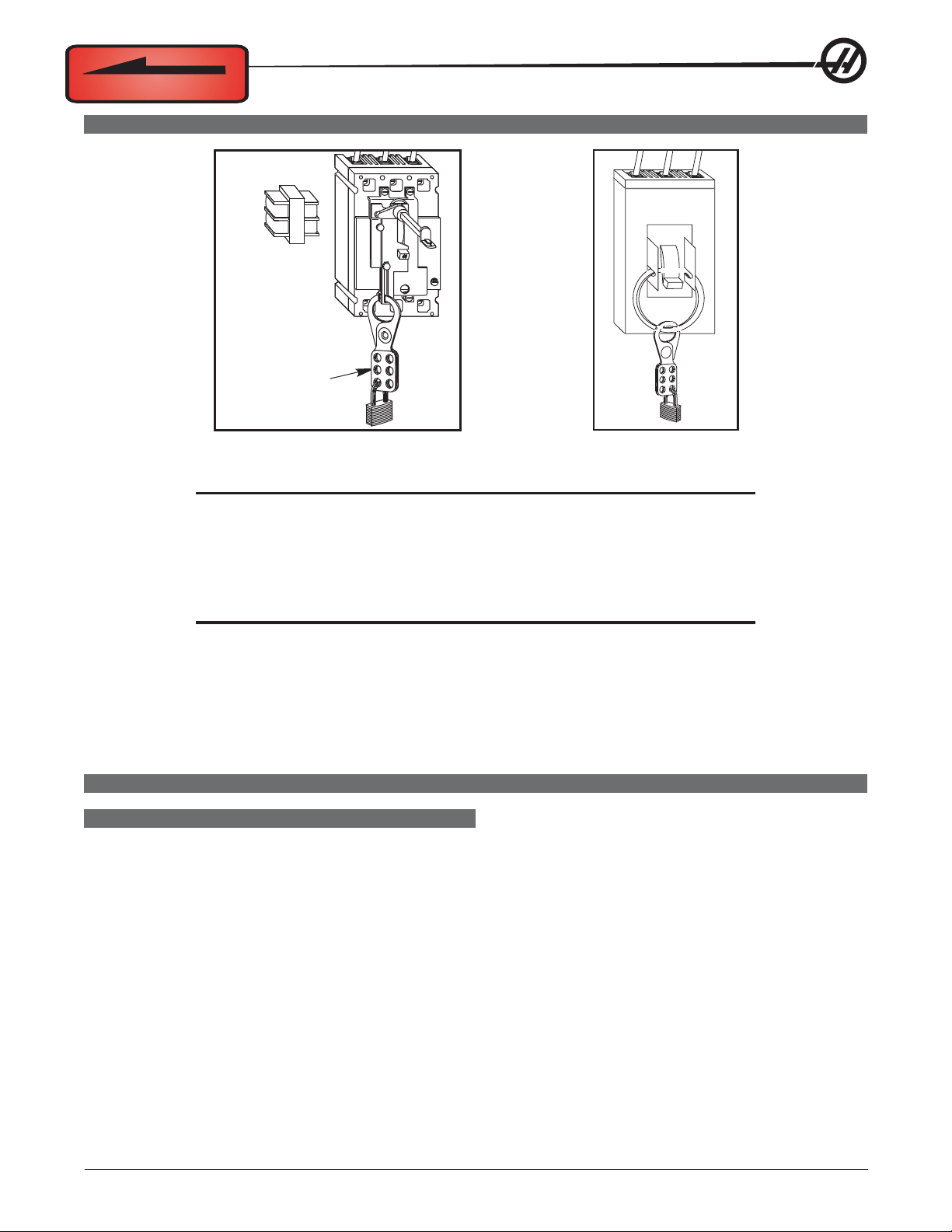
Install lock-out clasp
and lock with padlock
to secure Circuit
Breaker in the
OFF position.
T o avoid possible shock, make sure circuit breakers are appropriately locked of f before attempting any electrical work.
CAUTION! Working with the electrical services required for the machine can be
extremely hazardous. The electrical power must be off and steps must be
taken to ensure that it will not be turned on while you are working with it.
In most cases this means turning off a circuit breaker in a panel and then
locking the panel door. However, if your connection is different or you are
not sure how to do this, check with the appropriate personnel in your
organization or otherwise obtain the necessary help before you continue.
BLK
ON
OFF
WARNING!WARNING!
WARNING!
WARNING!WARNING!
The electrical panel should be closed and the three screws/latches on
the door should be secured at all times except during installation and
service. At those times, only qualified electricians should have access to the panel. When the main circuit breaker is on, there is high
voltage throughout the electrical panel (including the circuit boards
and logic circuits) and some components operate at high temperatures. Therefore extreme caution is required.
GENERAL ELECTRICAL TROUBLESHOOTING
MACHINE NOT RUNNING
Machine cannot be powered on.
• Check input voltage to machine.
• Check main circuit breaker at top right of electrical cabinet; switch must be at the on position.
• Check overvoltage fuses.
• Check wiring to Power Off button on front control panel.
• Check wiring to Auto Off relay to I/O PCB.
• Check connection between 24V transformer and K1 contactor.
• Check I/O PCB.
• Check Power PCB.
96-0284 rev C June 2007
Electrical Service
1
Page 3

Machine can be powered on, but turns off by itself.
• Check Settings #1 and #2 for Auto Off Timer or Off at M30.
• Check alarm history for Overvoltage or Overheat shutdown.
• Check AC power supply lines for intermittent supply.
• Check low voltage power supply for intermittent supply.
• Check wiring to Power Off button on front control panel.
• Check connection between 24V transformer and K1 contactor.
• Check I/O PCB.
• Check Parameter 57 for Power off at E-Stop.
• Check MOTIF or MOCON PCB.
Machine turns on, keyboard beeps, but no LCD/CRT display.
• Check for power connections to LCD/CRT from I/O PCB. Check for green Power LED at front of LCD/CRT.
• Close doors and zero return machine (possible bad monitor).
• Check video cable from Video PCB to LCD/CRT.
• Check for lights on the processor.
• Replace LCD/CRT.
Machine turns on, LCD works, but keyboard keys do not work.
• Check keyboard cable (700) from Video to SKBIF PCB.
• Check keypad.
• Check SKBIF PCB.
Constant E-Stop Condition (will not reset) (Vertical Machines).
• Check hydraulic counterbalance pressure, low pressure switches, and cabling.
Quad APC trouble shooting
The Quad APC uses an additional PC board to control pallets 3 and 4.
The pallet chain motor receives 160VDC from plug 6A on this board (32-3078A). The PC board receives power
(115V) from the power card, which plugs into P4 on the APC board.
The solenoid for the left, air operated, automatic door plugs into P3; this cable is part of 33-6038A. Pallet 3 and
4 signals are sent through cable 33-1516, which plugs into P1. The cable’s other end plugs into the I/O board
P62.
ELECTRICAL ALARM TROUBLESHOOTING
Axis Drive Fault Alarm
• Blown amplifier - indicated by light at bottom of amplifier when power is on. Replace the fuse in the amplifier.
• Amplifier or MOCON is noise sensitive. If this is the case, the alarm can be cleared and the axis will run
normally for a while.
T o check an amplifier, switch the motor leads and control cables between the amplifier and the one next to it. If
the same problem occurs with the other axis, the amplifier must be replaced. If the problem stays on the same
axis, either the MOCON or control cable. The problem could also be the axis motor itself, with leads either
shorted to each other or to ground.
2
Electrical Service
96-0284 rev C June 2007
Page 4

• Amplifier faulting out for valid reason, such as overtemp, overvoltage, or +/-12V undervoltage condition. This
usually results from running a servo intensive program, or unadjusted 12V power supply. Adjust voltage to
correct specifications or replace the power supply .
Overvoltage could occur if regen load is not coming on, but this does not usually happen. The problem could
also be the axis motor itself, with leads either shorted to each other or to ground.
Axis Overload
• The fuse function built into the MOCON has been overloaded. This may be caused by a lot of motor accel/
decels, or hitting a hard stop with the axis. This safety function protects the amplifier and motor . If the current
program is the cause, change the program. If the axis hits a hard stop the travel limits may be set wrong.
Phasing Error
• The MOCON did not receive the proper phasing information from the motors. Do not reset the machine if this
alarm occurs. Power the machine down and back up. If the problem persists, it is probably a broken wire or
faulty MOCON connectors. This problem could also be related to the Low Voltage Power Supply. Check to see
if the LVPS is functioning properly.
Servo Error Too Large
• This alarms occurs when the difference between the commanded axis position and the actual position
becomes larger than the maximum that is set in the parameter.
This condition occurs when the amplifier is blown, is not receiving the commands, or the 320V power source is
dead. If the MOCON is not sending the correct commands to the amplifier, it is probably due to a broken wire,
or a Phasing Error that was generated.
Axis Z Fault or Z Channel Missing
• During a self-test, the number of encoder counts was found to be incorrect. This is usually caused by a noisy
environment, and not a bad encoder. Check all shields and grounds on the encoder cables and the motor leads
that come into the amplifiers. An alarm for one axis can be caused by a bad grounding on the motor leads of
another axis.
Axis Cable Fault
• During a self-test, the encoder cable signals were found to be invalid. This alarm is usually caused by a bad
cable, or a bad connection on the motor encoder connectors. Check the cable for any breaks, and the encoder
connectors at the motor controller board. Machine noise can cause this alarm, although it is less common.
Alarm 101, "MOCON Comm. Failure"
• During a self-test of communications between the MOCON and main processor, the main processor does not
respond, and is suspected to be dead. This alarm is generated and the servos are stopped. Check all ribbon
cable connections, and all grounding. Machine noise can also cause this alarm, although it is less common.
Alarm 157, MOCON Watchdog Fault
• The self-test of the MOCON has failed. Replace the MOCON.
Alarm 212, Program Integrity Error/Alarm 250, Program Data Error
• If a program has been corrupted in the system or a corrupted program has been loaded into the machine, a
Program Data Error (250) or Program Integrity Error (212) might occur. This occurrence can be recognized by
an exclamation point (!) next to a program when turning to the list program page. Following is the common
procedure to perform when this happens.
1. Save all programs to disk except the program with the exclamation point error signal. The exclamation
point (!) indicates the program that is corrupt. This will be your back-up disk to reload the programs into the
machine.
2. Delete all the programs. This should delete all the programs including the one with the “!” error signal.
3. If the program with the exclamation point (!) does not erase then the control needs to be initialized.
96-0284 rev C June 2007
Electrical Service
3
Page 5

4. If the machine still has the program with the exclamation point or the control now refuses to load a good
program, it may be necessary to clear memory and reload software.
5. If problem persists, replace main processor board.
Alarm 261, Rotary CRC Error (Horiz & Vert)
• This alarm is normally the result of an incomplete software installation. To correct this error, Change Setting
30 to any selection but Off (note the original selection), then go to Parameter 43 and change one of the bits
from 1 to 0 or vice versa and press Write (the bit must be changed from its original value to its alternate value).
Simply changing the Setting and Parameter bit from one value to another and then back again corrects the
fault, and will clear any further occurrences of the alarm. Change the bit and Setting 30 back to their original
values. Press Reset to clear the alarms or cycle power to the machine.
Alarm 354, Aux Axis Disconnected (Lathe)
When this alarm is generated, do not press Reset. Turn Setting 7 Off. Enter Debug mode, then view the
Alarms/Messages page. On the Messages page, a code will appear similar to WO1. The list of codes and their
descriptions follows :
WO1 Power was just turned on or failed. Check the ribbon cables from the Aux Axis PCB to the proces-
sor for correct routing. Check for communication problems between the processor and the Aux
Axis PCB.
WO2 Servo following error too large. Check the encoder for contamination or dirt. Check for an intermit-
tent connection at both ends of the motor cable.
WO3 Emergency Stop. The E-STOP button was pressed, or an E-STOP condition occurred.
WO4 High load. Check for binding in the tool changer gearbox and motor. Rotate the carousel by hand
and feel for any binding. Make sure the toolholders are the correct weight.
WO5 Remote RS-232 commanded off. Check the ribbon cable and the voltage to the Aux Axis PCB.
Check for 115V AC (minimum) to the Aux Axis PCB from the main transformer. Check the fuse
holder and the fuse that is protecting this circuit.
WO6 Air or limit switch or motor overheat. Check that the motor is not hot. Check for any binding in the
motor. Check for overweight tooling.
WO7 Z channel fault. Either the encoder or the cable is bad. Change the encoder first, as it is easier to
change than the cable. If the problem persists, change the cable.
WO8 Over-current limit, stalled or PCB fault. Check for binding in the tool changer gearbox. Make sure
the belt is not too tight. Ohm out the motor cable, checking pins G to F (should be open), G to H
(should be open), and F to H (should read between 2.5 and 5 ohms). Check all the connections on
the Aux Axis PCB and motor cable.
WO9 Encode ES. Z channel is missing. Bad encoder or cable. See WO7.
WOA High voltage. Check the incoming voltage to the Aux Axis PCB. Incoming voltage must be 115V
AC. See WO5.
WOB Cable fault. Check the cable from the motor to the Aux Axis PCB. Check for loose connections at
each end.
4
Electrical Service
96-0284 rev C June 2007
Page 6
LINE VOLTAGE ADJUSTMENTS
Please read this section in its entirety before attempting to adjust the line voltage.
T ools Required: Large flat tip screwdriver, Digital voltmeter
NOTE: The machine must have air pressure at the air gauge, or a "Low Air Pressure"
alarm will be present on power up.
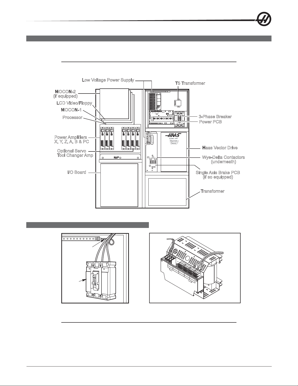
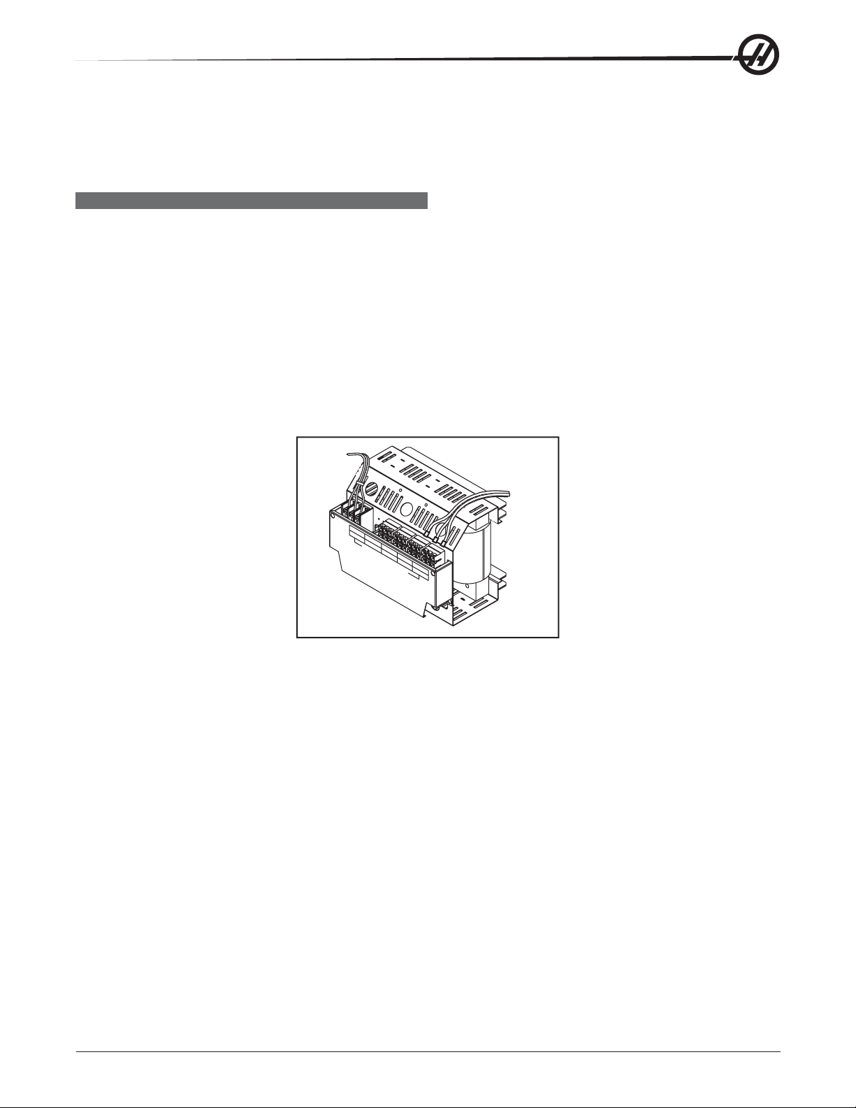
Low Voltage Power Supply
MOCON-2
(if equipped)
LCD Video/Floppy
MOCON-1
Processor
Power Amplifiers
X, Y, Z, A, B & PC
Optional Servo
Tool Changer Amp
I/O Board
SERVODRIVE
ASSEMBLY
Control Cabinet General Overview
T5 Transformer
3-Phase Breaker
Power PCB
Haas Vector Drive
Wye-Delta Contactors
(underneath)
Single Axis Brake PCB
(if so equipped)
Transformer
ELECTRICAL CONNECTIONS
Ouput
Power
Ground Line
Main
Circuit
Breaker
L1 L2
L3
TB2
240VOUT
D
A
488-458V
N
G
E
R
!
120VOUT
457-429V
260-244V
INCOMINGLINE VOLTAGETAPS (74,75, 76)
428-403V
243-227V
!
!
H
I
G
H
V
O
L
TB1
T
A
402-377V
226-211V
376-354V
210-195V
G
E
D
A
N
G
E
R
!
!
!
Input
Power
1. Hook up the three power lines to the terminals on top of the main circuit breaker at the upper right-hand
side of the electrical panel. Connect the separate ground line to the ground bus to the left of the terminals.
NOTE: Ensure service wires go into terminal-block clamps. (Do not miss clamp and
tighten screw. Connection looks fine but machine runs poorly - servo over-
loads.) To check, pull on wires after screws are tightened.
96-0284 rev C June 2007
Electrical Service
5
Page 7
2. After the line voltage is connected to the machine, make sure that main circuit breaker is off. Turn on the
power at the source. Using an accurate digital voltmeter and appropriate safety procedures, measure the
voltage between all three pair phases at the main circuit breaker and write down the readings. The voltage
must be between 195 and 260V (360 and 480V for high voltage option).
NOTE: Wide voltage fluctuations are common in many industrial areas; you need to
know the minimum and maximum voltage which will be supplied to the
machine while it is in operation. U.S. National Electrical Code specifies that
machines should operate with a variation of +5% to -5% around an average
supply voltage. If problems with the line voltage occur, or low line voltage is
suspected, an external transformer may be required. If you suspect voltage
problems, the voltage should be checked every hour or two during a typical day
to make sure that it does not fluctuate more than +5% or -5% from an average.
CAUTION! Make sure the main circuit breaker is set to off and the power is off at the
supply panel before changing the transformer connections. Make sure that
all three black wires are moved to the correct terminal block and are tight.
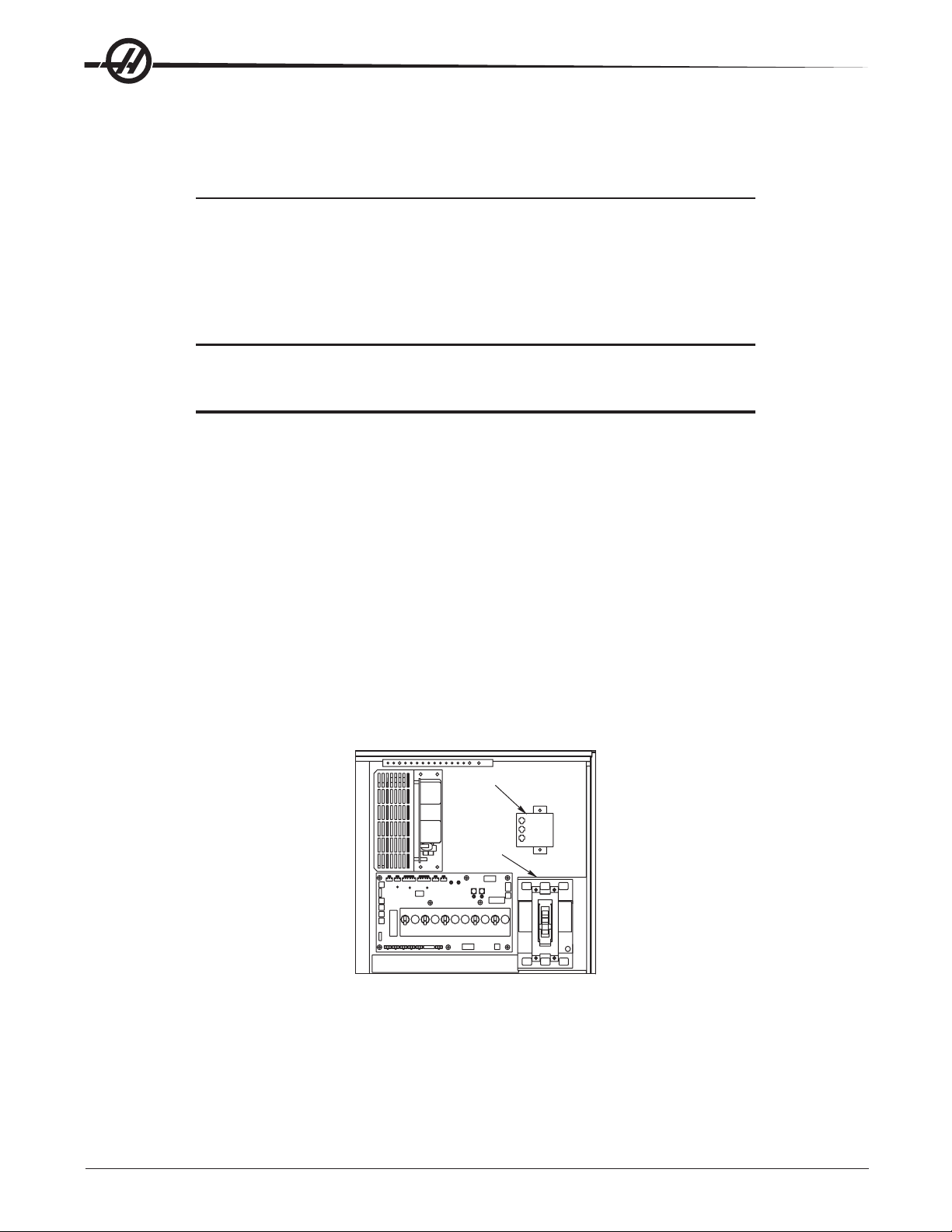
3. Check the connections on the transformer at the bottom-right corner of the rear cabinet. The three black
wires labeled 74, 75, and 76 must be moved to the terminal block triple which corresponds to the average
voltage measured in step 2 above. There are four positions for the input power for the 260V transformer and
five positions for the 480V transformer. The labels showing the input voltage range for each terminal position
are as shown in the previous illustration.
4. Transformer T5 supplies 24V AC used to power the main contactor. There are two versions of this transformer for use on 240 and 400V machines (32-0964B and 32-0965B, respectively). The 240V transformer
has two input connectors located about two inches from the transformer, which allow it to be connected to
either 240V or 200V. Users that have 220V-240V RMS input power should use the connector labeled 200V.
Users with the External High Voltage Option should use the 240V connector if they have 420V-510V 60Hz
power or the 200V connector if they have 50Hz power. Failure to use the correct input connector will result
in either overheating of the main contactor or failure to reliably engage the main contactor .
5. Set the main circuit breaker to ON and check for evidence of problems, such as the smell of overheating
components or smoke. If such problems are indicated, immediately set the main circuit breaker to OFF
and call the factory before proceeding.
T5 Transformer
Main
Circuit
Breaker
WARNING!
Through the Spindle Coolant (TSC) pump is a three phase pump and
must be phased correctly! Improper phasing will cause damage to the
TSC pump and void the warranty. Refer to the TSC start up section if
your machine is equipped with TSC.
6
Electrical Service
96-0284 rev C June 2007
Page 8
6. After the power is on, measure the voltage across the bottom terminals on the main circuit breaker. It
should be the same as the measurements where the input power connects to the main circuit breaker . If
there are any problems, check the wiring.
7. Apply power to the control by pressing the Power On switch on the front panel. Check the high voltage
buss on the Vector Drive (pin 2 with respect to pin 3 on the terminal bus at the bottom of the drive). It must
be between 310 and 360V. If the voltage is outside these limits, turn off the power and recheck steps 2 and
3. If the voltage is still outside these limits, call the factory. Next, check the DC voltage displayed in the
second page of the Diagnostic data on the CRT. It is labeled DC BUS. Verify that the displayed voltage
matches the voltage measured at pins 2 and 3 of the Vector Drive +/- 7V DC.
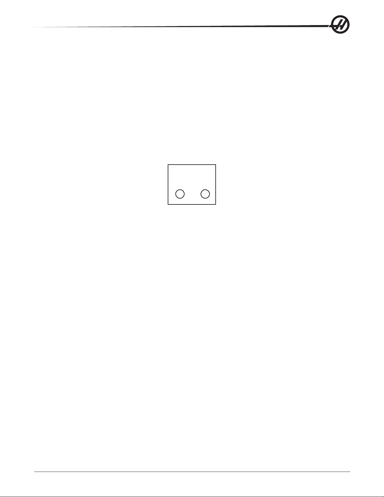
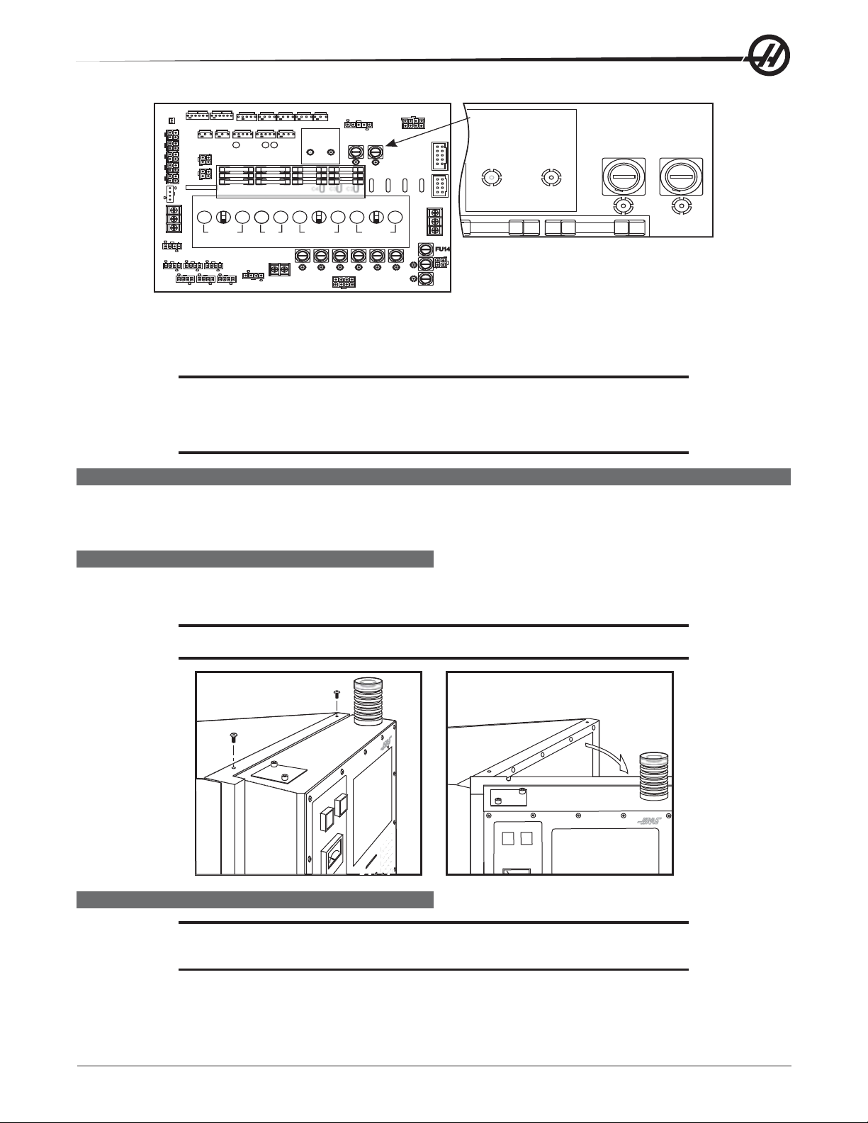
8. Electrical power must be phased properly to avoid damage to your equipment. The Power Supply Assembly PC board incorporates a "Phase Detect" circuit with neon indicators, shown below (disregard for single
phase machines). When the orange neon is lit (NE5), the phasing is incorrect. If the green neon is lit
(NE6), the phasing is correct. If both neon indicators are lit, you have a loose wire. Adjust phasing by
swapping L1 and L2 of the incoming power lines at the main circuit breaker.
PHASE DETECT
(FOR 3 PHASE ONLY)
PASS FAIL
NE5NE6
WARNING!
All power must be turned off at the source prior to adjusting phasing.
9. Turn of f the power at the main circuit breaker, close the door , lock the latches, and turn the power back on.
10. Remove the key from the control cabinet and give it to the shop manager.
96-0284 rev C June 2007
Electrical Service
7
Page 9
FUSE REPLACEMENT
Please read this section in its entirety before attempting to replace any fuses.
Some of the brushless amplifiers have one 15 amp fuse, F1. If this fuse blows, the associated motor will stop;
a light on the amplifier will tell of a blown fuse. Use the Amplifier Fuse Kit (Haas P/N 93-1089) to replace the
fuse. If the fuse blows again, the amplifier may be damaged, and needs to be replaced.
The Power PCB contains three ½-amp fuses located at the top right (FU1, FU2, FU3). If the machine is subject
to a severe overvoltage or a lightning strike, these fuses will blow and turn off all power. Replace these fuses
only with the same type and ratings. FU 4, 5, and 5A protect the chip conveyor (FU6 is only used with 3 phase
motors).
Size Fuse Name Type Rating (amps) Voltage Location
5mm FU1-FU3 Slo-Blo ½ 250V PSUP pcb, upper right
1/4 F1 Ultra fast 15 250V Amplifier (X, Y, Z, A, B)
5mm FU4, 5 Fast blow 5A 250V PSUP, bottom right corner
OVERVOLTAGE FUSES
WARNING!
The electrical panel will have residual voltage, even after power has
been shut off and/or disconnected . Never work inside this cabinet
until the small green Power On light on the servo amplifiers (servo
drive assembly on brush machines) goes out. The servo amplifiers/
servo drive assembly is on the left side of the main control cabinet
and about halfway down. This light(s) is at the top of the circuit card at
the center of the assembly. Until this light goes out, there are dangerous voltages in the assembly even when power is shut off.
1. Turn machine power off.
2. Turn the main switch (upper right of electrical cabinet) to the off position.
POWER
AIN
M
ON
OFF
3. Open the cabinet door and wait until the red charge light on the servo drive assembly goes out before
beginning any work inside the electrical cabinet.
4. The three overvoltage fuses are located in a row at the upper right of the Power Supply board. An orange
light will be on to indicate the blown fuse(s).
8
Electrical Service
96-0284 rev C June 2007
Page 10
P1
P5
P7
32-4076GRev.A
10A 115V
MAIN
P15
P14
SPAREFUSES
10A115V
RTY/
USER POWER
P28P30P33P34P35
PHASE DETECT
(FOR3 PHASE ONLY)
PASS FAIL
NE6
C4 C3 C2 C7 C6 C5 C1
10A230V
COOLANT
FU7
NE4
TB2
P25
FU1
NE5
NE1
10A230V
TSC COOLANT
NE11 NE10 NE9 NE8
P24
HASE DETECT
FU3
NE3
(FOR 3 PHASE ONLY)
PASS FAIL
NE6
NE5
NE1
FU1
FU3
NE3
TB3
FU8FU12 FU11 FU10 FU9
NE13
NE12
FU13
FU12
NE7
Power Supply Board; Fuse Locations
5. Using a flat tip screwdriver, turn the fuse(s) counterclockwise to remove the fuses. Replace the fuse(s) with
one having the same type and rating (½ amp, type AGC, 250V).
CAUTION! When the left fuse is blown, it is still possible to operate the machine,
thereby making an overvoltage situation possible. Verify absolute voltage
to the machine does not exceed 200V (max 260 leg to leg or leg to ground,
or 400V on high voltage machines - max 520V leg to leg or leg to ground).
FRONT PANEL
Please read this section in its entirety before attempting to replace any control panel
component.
SL-10 PENDANT COMPONENTS ACCESS
The SL-10 pendant door hinges on the left side. Remove the two (2) screws on top of the pendant in order to
open the pendant door.
CAUTION! Do not pinch the cable as the door is closed.
LCD ASSEMBLY REPLACEMENT
CAUTION! Use an electrostatic discharge (ESD) strap on wrist when working inside
the pendant.
1. Turn the power off and disconnect power to the machine.
96-0284 rev C June 2007
Electrical Service
9
Page 11
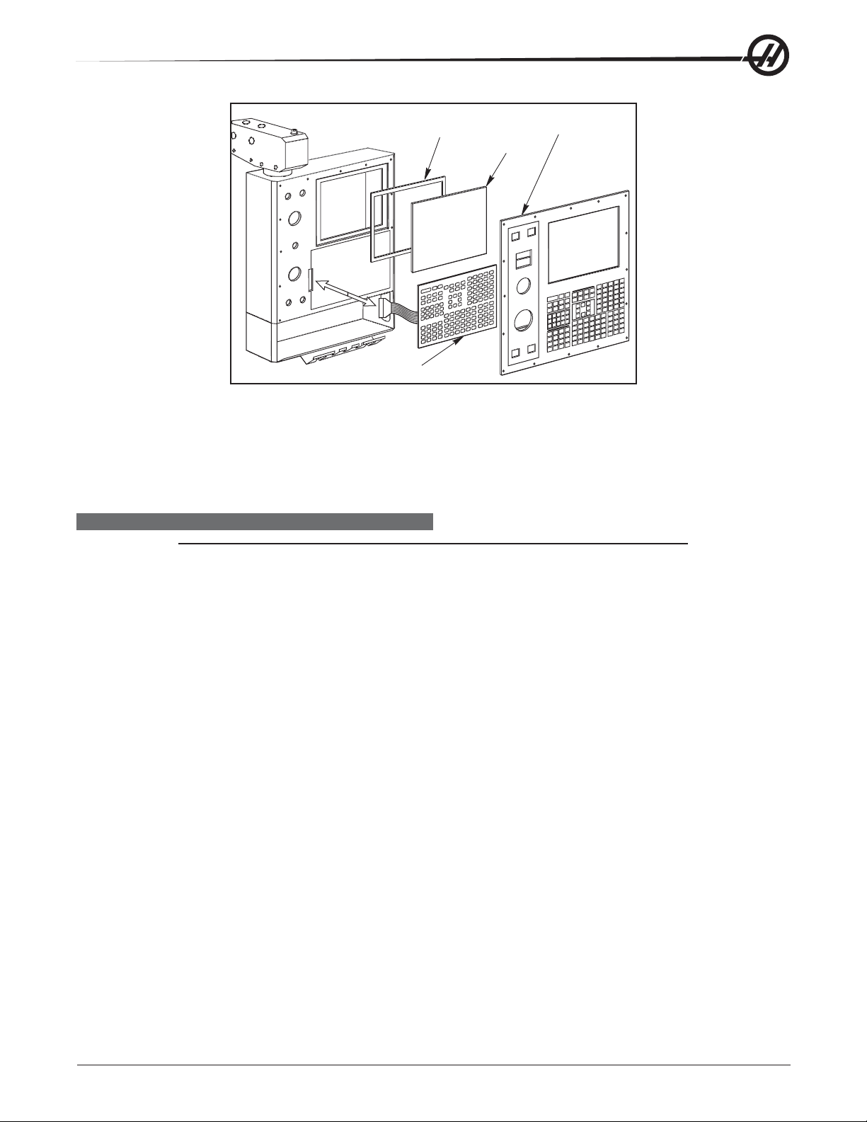
2. Remove the screws holding the cover on the back of the control panel. Take care to hold the cover in place
until all screws have been removed.
3. Disconnect the data cable from the receiver board on the LCD assembly (J3). Disconnect the power cable
and ground wire from the power supply board on the LCD assembly (TB1). Disconnect the cables to the
keyboard from the receiver assembly (P1) and power supply (TB2) on the LCD assembly.
4. Remove the four (4) hex nuts and washers beginning with the bottom, then remove the LCD assembly and
set aside in a safe place.
CAUTION! Do not drop or damage the LCD when removing it from the control panel.
5. Use gloves to avoid getting fingerprints on the new LCD. Position the assembly onto the four bolts (two
each on top and bottom). Place the washers and hex nuts on the bolts to hold in place. Once all washers
have been attached and nuts have been hand-tightened, tighten down completely .
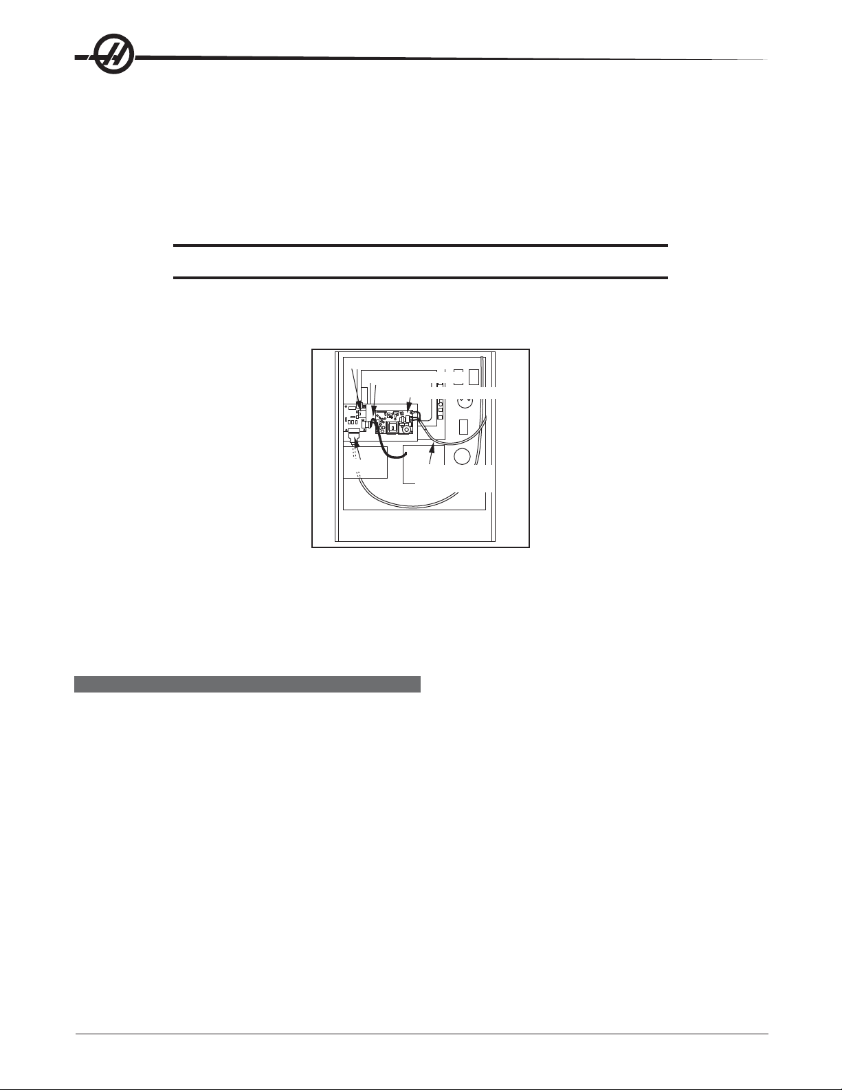
Receiver Assembly
Keyboard Cables
Power Supply Board
Data Cable
Back of Operator’s Pendant
Power Supply
Cable
6. Plug the keyboard cables into the new receiver board (P1) and the power supply (TB2). Plug the power
cable into the power supply board (TB1) and attach the green wire to ground. Plug the data cable into the
receiver board (J3).
7. Replace the back cover panel and attach with the four screws previously removed.
JOG HANDLE
The Jog handle is actually a 100-line-per-revolution encoder, used to move one axis at a time. If no axis is
selected for jogging, turning the handle has no effect. When the axis moved reaches its travel limits, the handle
inputs will be ignored in the direction that would exceed the travel limits. Parameter 57 bit 0 can be used to
reverse the direction of operation of the handle.
Jog Handle Replacement
1. Turn the machine power off.
2. Remove the screws holding the cover on the back of the pendant. Take care to hold the cover in place until
all screws have been removed.
3. Unplug the cable leading to the jog handle encoder.
10
Electrical Service
96-0284 rev C June 2007
Page 12
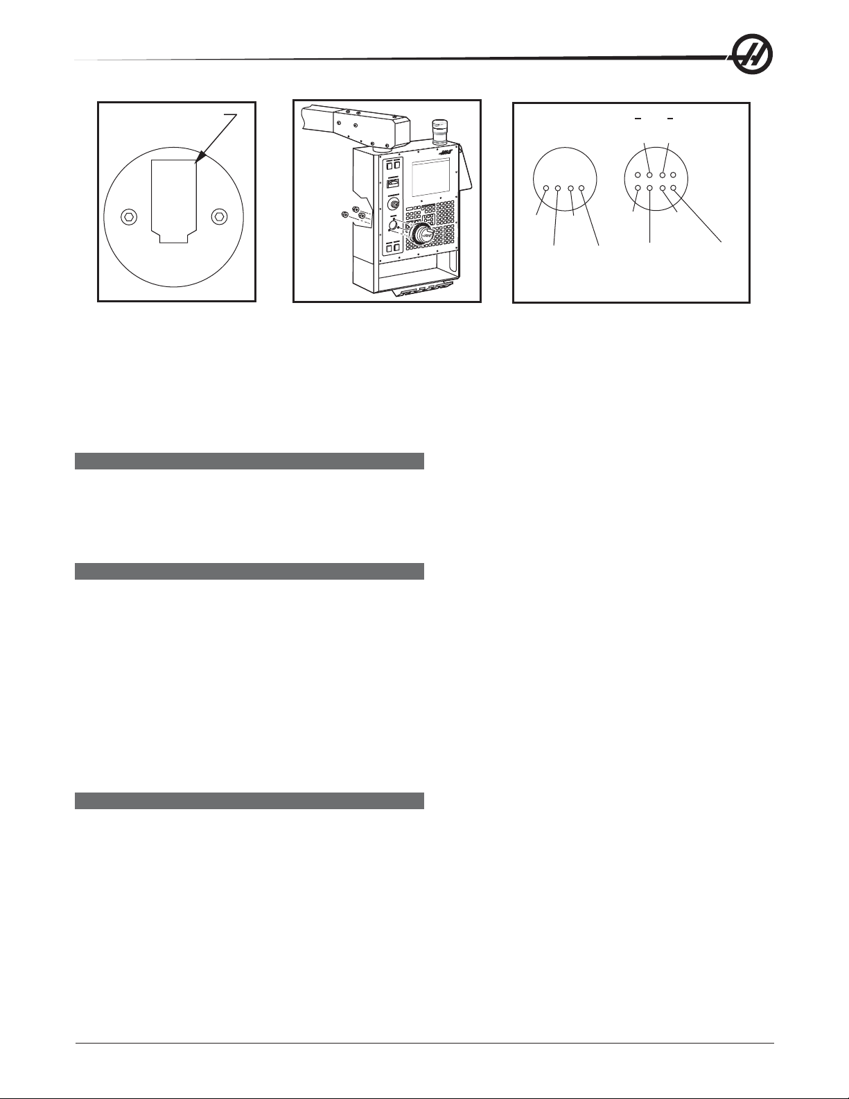
Blank pin goes to this
side of connector
A
YEL
B
BRN
B
GRN
+5V
RED
GND
WHT/
RED
+5V
BLK
Jog Handle Encoder Jog Handle Removal Jog Handle Wiring Diagram
A
RED
GND
WHT
A
WHT/
YEL
B
WHT/
BRN
4. Using the 5/64" allen wrench, loosen the two screws holding the knob to the control panel and remove.
5. Remove the three screws holding the jog handle encoder to the control panel and remove.
6. Replacement is reverse of removal. Important! The blank pin side of the connector must face as shown
below when reconnecting; otherwise, damage may occur to the machine.
POWER ON/OFF SWITCHES
The Power On switch engages the main contactor. The On switch applies power to the contactor coil and the
contactor thereafter maintains power to its coil. The Power Off switch interrupts power to the contactor coil and
turns power off. Power On is a normally open switch and Power Off is normally closed. The maximum voltage
on the Power On and Power Off switches is 24V AC and is present any time the main circuit breaker is on.
EMERGENCY STOP SWITCH
The Emergency Stop switch is normally closed. If the switch opens or is broken, servo power is removed
instantly. This will also shut off the turret, spindle drive, and coolant pump. The Emergency Stop switch will
shut down motion even if the switch opens for as little 0.005 seconds. Note that if Parameter 57 bit 3 is set to
1, it will cause the control to be powered down when Emergency Stop is pressed.
You should not normally stop a tool change with Emergency Stop as this will leave the tool changer in an
abnormal position that takes special action to correct
If the lathe turret or mill tool changer (T/C) becomes jammed, the control will automatically come to an alarm
state. To correct this, push the Emergency Stop button and remove the cause of the jam. Push the Reset key
to clear any alarms. Push Zero Return and the Auto All Axes to reset the Z-axis and turret or T/C. Never put
your hands near the turret or T/C when powered unless E-Stop is pressed.
KEYBOARD BEEPER
There is a beeper under the control panel that is used as an audible response to pressing keyboard buttons
and as a warning beeper. The beeper is a one kHz signal that sounds for about 0.1 seconds when any keypad
key, Cycle Start, or Feed Hold is pressed. The beeper also sounds for longer periods when an auto-shutdown is
about to occur and when the “Beep at M30” setting is selected.
If the beeper is not audible when buttons are pressed, the problem could be in the keypad, keyboard interface
PCB or in the speaker. Check that the problem occurs with more than one button and check that the beeper
volume is not turned down or disconnected. If lamps do not turn on, check the GFCI plug.
96-0284 rev C June 2007
Electrical Service
11
Page 13

LAMP ON/OFF SWITCH
An on/off switch is supplied for the work lamp. It is located on the side of the operator’s pendant. The lamp
uses 115V AC taken from P19 on the main power distribution board.
SWITCH REPLACEMENT
1. Turn the machine power off. Remove the screws holding the cover on the back of the pendant. Take care to
hold the cover in place until all screws have been removed.
2. Disconnect all leads to the switch connectors. Ensure all leads are properly marked for reconnecting later.
3. Unscrew the two small set screws, one on top and one on the bottom, and turn the switchcounterclock-
wise to loosen. Separate from the front portion and pull out.
4. To replace, screw the front and rear portions together (reverse of removal) and tighten down the two small
set screws when the switch is properly positioned.
NOTE: The Power On, Power Off, and Emergency Stop switches must all have the
connectors on the bottom of the switch.
5. Reconnect all leads to the correct switch.
SPINDLE LOAD METER
Load meter measures load on spindle motor as a percentage of rated continuous power of motor, with a slight
delay between a load and actual meter reflection. The eighth A-to-D input also provides a measure of spindle
load for cutter wear detection. Second page of diagnostic data displays % of spindle load. Meter should agree
with display within 5%. Spindle drive display #7 should also agree with load meter within 5%. Note there are
different types of spindle drives used in the control, all are equivalent in performance but are adjusted differently .
Spindle Load Meter Replacement
1. Turn the power off and disconnect power to the machine. Remove the screws holding the cover panel on
the back of the pendant. T ake care to hold the cover panel in place until all screws are removed.
2. Disconnect the two leads at the back of the spindle load meter assembly. Ensure the two leads are
properly marked for reconnecting later .
3. Unscrew the four screws that hold the spindle load meter assembly to the control panel. Take care to hold
the assembly in place until all screws have been removed. Remove the assembly.
4. Installation is reverse of removal. Ensure leads go to the correct location.
KEYPAD REPLACEMENT
1. Turn the power off and disconnect power to the machine. Remove the screws holding the rear cover to the
back of the pendant. Take care to hold the cover in place until all screws are removed.
2. Unplug the keypad's 24-pin ribbon cable from the Keyboard Interface board.
3. Remove the screws from the front of the pendant. Take care to hold the cover in place until all screws have
been removed. Remove the pieces and set aside in a safe place.
4. Using a flat, blunt tool, such as putty knife, pry the keypad away from the control panel. Pull the ribbon
cable through the opening in the control to remove.
5. To replace, first put the bezel spacer in place and fasten temporarily with screws in the top corners.
12
Electrical Service
96-0284 rev C June 2007
Page 14
Gasket
Glass
Keypad
Keypad Installation
Front Bezel
6. Insert the ribbon cable through the opening in the control panel. Expose the adhesive strip on the back of
the keypad and press it into place in the upper right corner of the keypad recess. Press to the control
panel to mount. Plug the ribbon cable into the Keyboard Interface board, taking care to not bend the pins.
7. Replace the front and rear cover panels and fasten with the screws that were previously removed.
SERIAL KEYBOARD INTERFACE REPLACEMENT
NOTE: Refer to "Cable Locations" for a diagram of this board.
1. Follow all precautions noted previously before working in the control cabinet.
2. Turn the main switch (upper right of electrical cabinet) to the off position.
3. Remove the four screws on the back of the control box, then remove the cover panel. Take care to hold the
panel in place until all screws have been removed.
4. Disconnect all leads to the Serial Keyboard Interface (SKBIF) board. Ensure all cables are properly la-
beled.
5. After all cables have been disconnected, unscrew the four screws holding the Serial KBIF board to the
control box. Take care to hold the board in place until all screws have been removed. Place the screws and
standoffs aside for later use.
6. Replace the Serial KBIF board, using the four screws previously removed. Starting at the top right, attach
each screw and standoff loosely , until all are mounted, then tighten down.
7. Reconnect all cables to the Serial KBIF board at their proper locations.
8. Verify whether the machine is equipped with either a speaker or a beeper. Align the toggle switches of
Switch 1 on the Serial KBIF board to their appropriate positions. Beeper operation requires that both S1
switches be set to ‘B’; speaker operation requires that both S1 switches be set to ‘S’.
96-0284 rev C June 2007
Electrical Service
13
Page 15

SOLENOIDS
Please read this section in its entirety before attempting to replace any solenoid assemblies.
TOOL RELEASE PISTON (TRP) AIR SOLENOID ASSEMBLY (HORIZ & VERT)
Removal
1. Turn machine power on and raise spindle head to uppermost position, then turn the power off. Remove air
supply from machine.
2. Remove sheet metal at rear and/or top of machine to access the back of the spindle (Mechanical Service
manual).
3. Disconnect all air lines from the air solenoid assembly (Do not remove fittings). Disconnect the two leads
from the low air pressure sensor.
4. Unscrew the air solenoid assembly from the tool release piston assembly , taking care not disturb the
position of the clamp/unclamp switches. It may be necessary to remove the tool release piston to access
the solenoid assembly .
5. Unplug the wiring leading to the plug marked on the solenoid bracket as “880 from I/O PCB to Solenoid
Valves” and the plug marked “Spare”.
6. Unscrew the air solenoid from the air solenoid assembly. Remove the SHCS holding the assembly to the
bracket and remove the assembly .
Installation
1. Install the new air solenoid. Take care to not disturb the position of the clamp/unclamp switches.
2. Replace air solenoid assembly and attach to bracket with the SHCS previously removed. Tighten securely.
3. Reinstall the tool release piston assembly if removed (see Mechanical Service).
4. Reconnect the two leads to the low air preassure sensor. Reconnect wiring to plugs on solenoid bracket.
5. Ensure all air lines are reconnected to their proper fittings. Reconnect air supply to the machine, and
check for leaks.
6. Replace the sheet metal.
14
Electrical Service
96-0284 rev C June 2007
Page 16
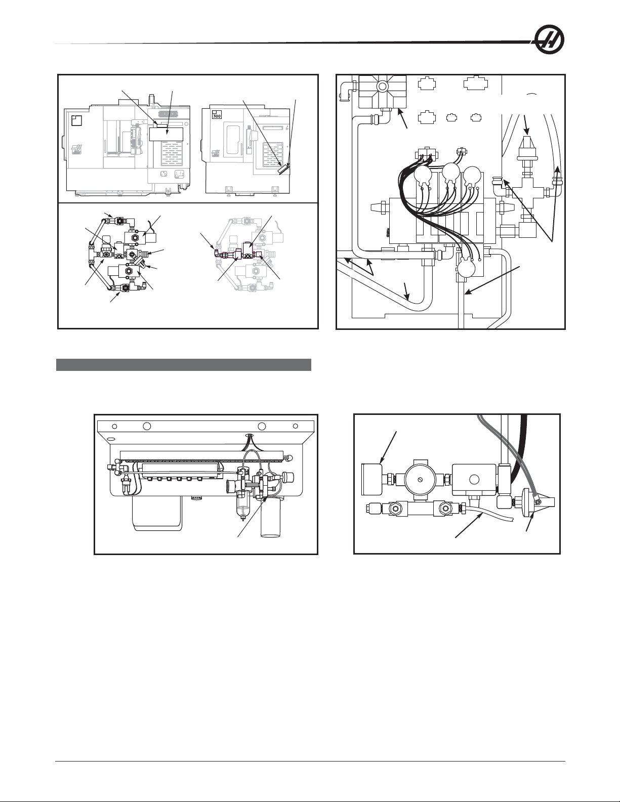
Air Solenoid
Assembly
EC
400
Motor Shroud
Air Solenoid
Assembly
EC
Sheet Metal
Tray
Low air pressure
sensor
Air solenoid
assembly
Check Valve Switch
Pre-
Charge
TRP Solenoid
To TSC
TSC Solenoid
Inlet
Pressure
Switch
Regulator
Check Valve Switch
TRP
Solenoid
Basic Air Solenoid Assembly
Check
Valve
Switch
Junction
Elbow
Air Solenoid Assembly
With TSC Feature Added
Disconnect
all air lines
Locations of EC-300 and EC-400 TRP Solenoids VF-Series Air Solenoid Assembly
SPINDLE LUBE AIR SOLENOID
Removal
1. Turn the machine power off and remove the air supply from the machine.
Pressure Gauge
Disconnect
all air lines
Spindle
Lube
Solenoid
Lube Line
Lube/Air Panel (Rear V iew) Spindle Lube/Air Solenoid Assembly (Top View)
2. a. Lathe: Disconnect the lube line from the spindle lube air solenoid assembly.
b. Mill: Disconnect the air lines from the spindle lube air solenoid assembly.
3. Disconnect the electrical leads from the main air line pressure switch.
4. Lathe: Unscrew the solenoid assembly pressure gauge from the assembly.
5. Unscrew the entire solenoid assembly from the T-fitting.
Installation
1. Reattach the solenoid assembly at the T-fitting.
2. a. Lathe: Replace the pressure gauge on the solenoid assembly and reconnect the lube line.
b. Mill: Reconnect all air lines.
96-0284 rev C June 2007
Electrical Service
Main Air Line
Pressure Switch
15
Page 17
3. Reconnect the electrical leads to the main air line pressure switch.
4. Restore the air supply to the machine.
PNEUMATIC CHUCK/TURRET CLAMP/UNCLAMP SOLENOID (LATHE)
Removal
1. Turn machine power off and remove the air supply from the machine.
2. Pneumatic Chuck: Disconnect the two air hoses from the pneumatic chuck clamp/unclamp solenoid.
Turret: Disconnect the three air hoses from the turret clamp/unclamp solenoid (see the Turret In/Out
Adjustment), and disconnect exhaust lines.
3. Unplug the solenoid electrical lead (located on the rear of the lube air panel).
4. Remove the two SHCS holding the assembly to the bracket and remove the assembly.
Installation
1. Replace the air solenoid assembly and attach it to the bracket with the two SHCS. Tighten securely.
2. Reconnect the electrical connection to the solenoid at the switch bracket.
3 Reconnect the two (three for Turret) air lines and turret exhaust lines, ensuring that all connections are
tight and do not leak.
4. Restore the air supply to the machine.
SMART AMPLIFIER
The Smart Amplifier has a microprocessor incorporated in the design. This allows the amplifier to detect and
report detailed alarms. The software level necessary to display these new alarms is 15.02A or newer.
The Smart Amplifier is backward compatible to any machine that has a Vector Drive. New Smart Amplifiers and
standard amplifiers may be used in any combination in the machine. However , if the machine does not have at
least 15.02A software or newer the specific Smart Amplifier will not be displayed. The Smart Amplifier and the
standard amplifier use the same Parameters. On non-thin pendant machines, at least two of the standard
amplifiers must be used.
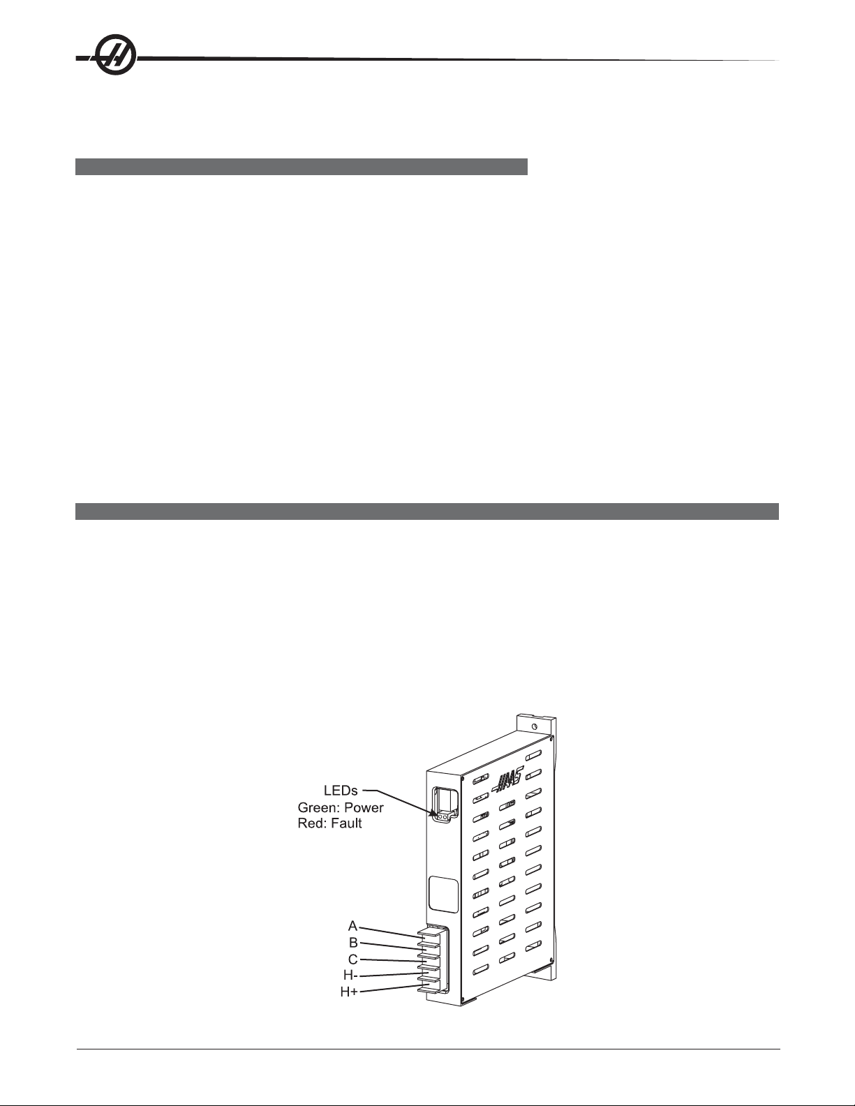
The Smart Amplifier does not have a 12VDC connector, and both the Fault (Red LED) and the Run (Green LED)
are relocated. The 320VDC (H+ and H-) and the X, Y and Z-axis connections are also relocated.
16
Electrical Service
96-0284 rev C June 2007
Page 18
The smart amplifier will calibrate utilizing the microprocessor that is present in each of the Smart Amplifiers at
power up. When power is applied to the Control Cabinet the Fault (Red LED) will illuminate and stay illuminated
for a short time (approximately 5 seconds), this is called the “A” Phase Calibration. Then both LEDs will be out
for a few seconds; this is called the “B” Phase Calibration. Next the Run (Green LED) will illuminate, indicating
the Smart Amplifier is ready with no faults.
SMART VECTOR DRIVE
The smart vector drive features a microprocessor that allows it to detect and display specific alarms (software
version 15.02A or newer only). It is backward compatible to any machine with a vector drive regardless of
software version; however, the drive-specific alarms will not display in older software. Such alarms will display
in the same way as with old-style drives.
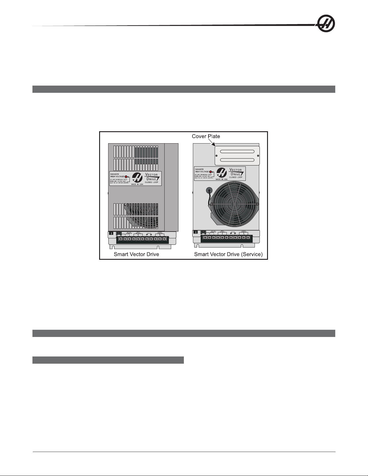
Smart vector drives installed in new machines include a cover, and the machines electrical cabinet door is cut
to accommodate it. Service drives are shipped without the cover for installation in older machines. When
replacing a drive in a machine built to accommodate the cover , use the cover from the old drive.
When installing a smart vector drive without the cover , install the cover plate to the front of the vector drive.
When installing with the cover, inst all the cover plate to the top of the vector drive.
You will also need several cables. Please see 93-32-5558A for the 40 HP drive and 93-32-5559A for the 20 HP
drive.
PCB REPLACEMENT
Please read this section in its entirety before attempting to replace any PCBs
MICROPROCESSOR ASSEMBLY
The microprocessor assembly is in the control cabinet at the top left position. It contains three large boards.
They are: Microprocessor, the Video/Keyboard and the MOCON. All three boards of the processor assembly
receive power from the low voltage power supply. The three PCBs are interconnected by a local buss on dual
50-pin connectors. At power-on, some diagnostic tests are performed on the processor assembly and any
problems found will generate Alarms 157 or 158. In addition, while the control is operating, it continually tests
itself and a self test failure will generate Alarm 152.
96-0284 rev C June 2007
Electrical Service
17
Page 19

MOCON, VIDEO/KEYBOARD, & MICROPROCESSOR
WARNING!WARNING!
WARNING!
WARNING!WARNING!
The electrical panel will have residual voltage, even after power has
been shut off and/or disconnected. Never work inside this cabinet
until the small red Charge light on the servo amplifiers go out. The
servo amplifiers are on the left side of the main control cabinet and
about halfway down. This light is at the top of the circuit card at the
center of the assembly. Until this light goes out, there are dangerous
voltages in the assembly even when power is shut off.
Ground straps must be used when handling boards.
NOTE: Board arrangement may differ from the order of replacement that follows.
Steps for replacement will only differ in which board may need to be removed
before getting to the necessary board.
MOTOR CONTROLLER (MOCON)
Machines are equipped with a microprocessor-based brushless motor controller board (MOCON) that replaces
the motor interface in the brush type controls. It runs in parallel with the main processor, receiving axis commands and closing the loop around the axis motors.
In addition to controlling the axis and detecting axis faults, the motor controller board (MOCON) is also in
charge of processing discrete inputs, driving the I/O board relays, commanding the spindle, and processing the
jog handle input. It also controls 6 axes, so there is no need for an additional board for a 5-axis machine.
Four LEDs are used to diagnose MOCON problems:
The RUN” LED will turn on, indicating that Mocon code was found in ROM and is being executed. This LED will
turn off if a processor exception causes the Mocon code to abort execution.
The “STAT” LED indicates the following (Specific to Mocon 11.00 or later software)
a. Continuously ON - Normal status. board has passed all power-on tests, and no problems have been
encountered
b. Blinks 3 times - Communication with main processor failed
c. Blinks 4 times - Internal ±12V testing failed
d. Blinks 5 times - Internal watchdog circuit failed
e.Blinks rapidly - EPROM CRC failed
The “Halt” LED glows when the board is in use (processing).
The “+5” LED lights when the board has power.
MOCON Board Replacement
1. Turn machine power off.
2. Turn the main switch (upper right of electrical cabinet) to the off position.
3. Open the cabinet door enough to safely work on the electrical panel. Wait until the red charge light on the
servo amplifiers (servo drive assembly on brush machines) goes out before beginning any work.
4. Disconnect all leads to the Motor Controller (MOCON) board, and ensure all cables are properly labeled.
5. After all cables have been disconnected, unscrew the standoffs, taking care to hold the board in place until
all standoffs have been removed.
18
NOTE: If the Video/Keyboard or Processor boards need replacing, skip the next step.
Electrical Service
96-0284 rev C June 2007
Page 20

6. Replace the MOCON board, attaching it to the Video/Keyboard (beneath the MOCON board) with the
standoffs, and reconnect all leads (previously removed) to their proper connections.
7. If a second MOCON board is present, be sure to connect the jumper on the second MOCON board.
VIDEO/KEYBOARD
The Video/Keyboard PCB generates the video data signals for the monitor and the scanning signals for the
keyboard. In addition, the keyboard beeper is generated on this board. There is a single jumper on this board
used to select inverse video. The video PCB connectors are:
P1 Power connector J11 SPARE
J3 Keyboard (700) J12 Floppy
J4 Address bus J13 Video (760)
J5 Data J14 RS422 B
J10 Floppy V+ J15 RS422 A
Video/Keyboard Replacement
1. Remove the MOCON board as previously described.
2. Disconnect all leads to the Video/Keyboard. Ensure all cables are properly labeled for reconnecting later.
3. After all cables have been disconnected, unscrew the standoffs, taking care to hold the board in place until
all standoffs have been removed.
NOTE: If the Processor board needs replacing, skip the next step.
4. Replace the Video/Keyboard, attaching it to the Processor board with the standoffs.
5. Reconnect all leads (previously removed) to their proper connections.
6. Replace the MOCON board.
MICROPROCESSOR PCB (68ECO30)
The Microprocessor PCB contains the 68ECO30 processor running at 40 MHz, one 128K EPROM; between
1MB and 16MB of CMOS RAM and betwen 512K and 1.5MB of Fast Static RAM. It also contains a dual serial
port, a battery to backup RAM, buffering to the system buss, and eight system status LED’s.
Two ports on this board are used to set the point at which an NMI is generated during power down and the point
at which Reset is generated during power down.
The eight LEDs are used to diagnose internal processor problems. As the system completes power up testing,
the lights are turned on sequentially to indicate the completion of a step. The lights and meanings are:
R UN Program Running Without Fault Exception. (Normally On) - If this light does not come on, or goes
out after coming on, there is a problem with the microprocessor or the software running in it. Check all
of the buss connectors to the other two PCBs and ensure all three cards are getting power.
PGM Program Signature Found in Memory. (Normally On) - If this light does not come on, it means that
the main CNC program package was not found in memory, or that the auto-start switch was not set.
Check that Switch S1-1 is on and the EPROM is plugged in.
CRT CRT/LCD Video Initialization Complete. (Normally On) - If the light does not come on, there is a
problem communicating with the Video PCB. Check buss connectors to ensure it is getting power.
MSG Power-on Serial I/O Message Output Complete. (Normally On) - If this light does not come on,
there is a problem with serial I/O or interrupts. Disconnect anything on the external RS-232 and retest.
SIO Serial I/O Initialization Complete. (Normally On) - If this light does not come on, there is a problem
with the serial ports. Disconnect anything on the external RS-232 and test again.
96-0284 rev C June 2007
Electrical Service
19
Page 21

PO R Power-On-Reset Complete. (Normally On) - If this light does not come on, there is a problem with
the Processor PCB. Check that the EPROM is plugged in. Test the card with buss connectors off.
HAL T Processor Halted in Catastrophic Fault. (Normally Dim) - If this light comes on, there is a problem
with the Processor PCB. Check that the EPROM is plugged in. Test the card with buss connectors off.
+5V +5V Logic Power Supply is Present. (Normally On) - If this light does not come on, check the low
voltage power supply and check that all three phases of 230V input power are present.
There is 1 two-position DIP switch on the Processor PCB labled S1. Switch S1-1 must be ON to auto-start the
CNC operational program. If S1-1 is OFF, the PGM light will remain off. Switch S2-1 is used to enable Flash. If
it is disabled it will not be possible to write to Flash.
The processor connectors are:
J1 Address buss J5 Serial port #2 (for auxiliary 5th axis) (850A)
J2 Data buss J3 Power connector
J4 Serial port #1 (for upload/download/DNC) (850) J6 Battery
Memory Retention Battery
The memory retention battery (3.3V Lithium battery) is soldered into the Processor PCB. It maintains the
contents of CMOS RAM during power off periods. A minimum voltage of 2.5V DC is required for proper operation. Prior to this battery being unusable, an alarm is generated indicating low battery. If the battery is replaced
within 30 days, no data is lost. The battery is not needed when the machine is powered on. Connector J6 on
the Processor PCB can be used to connect an external battery.
T o replace the battery , the 4-pin jumper , att ached to a fresh battery , has to be temporarily attached to J-6
before the old battery is removed. With the jumper in place, un-solder the old battery and remove. Install a new
battery and solder in place, then remove the temporary jumper.
NOTE: Do not attach the jumper after the old battery has been removed or remove the
jumper if a fresh battery has not been installed. This will result in complete
machine memory loss, which cannot be reversed.
Processor Board Replacement
1. Remove the MOCON board, and the Video/Keyboard as previously described.
2. Disconnect all leads to the Processor board. Ensure all cables are properly labeled for reconnecting later.
3. After all cables have been disconnected, unscrew the standoffs, taking care to hold the board in place until
all standoffs have been removed.
4. Replace the Processor board, attaching it to the electrical cabinet with the standoffs, reconnect all leads
(previously removed) to their proper connections, and replace Video/Keyboard and MOCON board.
INPUT/OUTPUT ASSEMBLY
The Input/Output Assembly consists of a single printed circuit board called the I/O PCB.
The I/O PCB also contains a circuit for sensing a ground fault condition of the servo power supply. If more than
1.75 amps is detected flowing through the grounding connection of the 160V DC buss, a ground fault alarm is
generated and the control will turn off servos and stop.
Relay K6 is for the coolant pump 230V AC. It is a plug-in type and is double-pole. Relays K9 through K12 are
also plug-in types for controlling the drawbar motors.
I/O Board Replacement
1. Follow all precautions noted previously before working in the electrical cabinet.
2. Disconnect all leads to the Input/Output board and move aside for removal. Ensure all cables are properly
labeled for reconnecting later.
20
Electrical Service
96-0284 rev C June 2007
Page 22
3. Remove the board by first removing the twelve screws that fasten it to the cabinet. Take care to hold the
board in place until all screws have been removed.
4. Replace the I/O board, attaching it to the cabinet with the twelve screws previously removed, and reconnect
all leads to the I/O board. Check for any additional jumper settings per I/O release notes.
POWER TRANSFORMER ASSEMBLY (T1)
The power transformer assembly converts three-phase input power (50/60Hz) to three-phase 230V and 115V
power . Two transformers are used, depending on the input volt age range. The low voltage transformer has four
input connections to allow for a range of voltages from 195V RMS to 260V RMS. The high voltage transformer
has five input connections and will accept a range of voltages from 354V RMS to 488V RMS.
The 230V is used to power the spindle drive. THe 230V also supplies the power to the vector drive, which
supplies 325V DC power for the axis servo amplifiers. The 115V is used by the video monitor, solenoids, fans
and pumps, in addition to supplying power to the main LVPS used by the control electronics.
The transformer assembly is located in the lower right hand corner of the main cabinet. Besides the high/low
voltage variations, two different power levels are available depending on the spindle motor used. The small and
large transformers have power ratings of 14 KVA and 28 KVA, respectively, and are protected by the main
circuit breaker.
Ouput
Power
Input
Power
TB2
240VOUT
488-458V
457-429V
260-244V
D
A
INCOMINGLINE VOLTAGETAPS (74,75, 76)
N
428-403V
G
E
243-227V
R
!
!
402-377V
!
H
226-211V
I
G
TB1
120VOUT
376-354V
H
V
210-195V
O
L
T
A
G
E
D
A
N
G
E
R
!
!
!
Polyphase Bank Transformer
Primary Connection To T1
Input power to T1 is supplied through CB1, the main circuit breaker. Three-phase 230 to T1 is connected to the
first three terminals of TB10.
Circuit breaker CB1 is used to protect the spindle drive and to shut off all power to the control. A trip of this
breaker indicates a serious overload problem and should not be reset without investigating the cause of the trip.
Main Contactor K1
Main contactor K1 is used to turn the control on and off. The Power On switch applies power to the coil of K1
and after it is energized, auxiliary contacts on K1 continue to apply power to the coil. The Power Off switch on
the front panel will always remove power from this contactor .
When the main contactor is off, the only power used by the control is supplied through two ½ amp fuses to the
circuit that activates the contactor. An overvoltage or lightning strike will blow these fuses and shut off the main
contactor.
The power to operate the main contactor is supplied from a 24V AC control transformer that is primary fused at
½ amp. This ensures that the only circuit powered when the machine is turned off is this transformer and only
low voltage is present at the front panel on/off switches.
96-0284 rev C June 2007
Electrical Service
21
Page 23

Voltage Selection Taps
There are four labeled plastic terminal blocks. Each block has three connections for wires labeled 74, 75, and
76. Follow the instructions printed on the transformer.
Secondary Connection To T1
The secondary output from T1 is 115V AC three-phase CB2 that protects the secondary of transformer T1 and
is rated at 25 amps.
Optional 480V Transformer
60Hz 50Hz
Input Voltage Range Tap Input Voltage Range Tap
493-510 1 (504) 423-440 1 (504)
481-492 2 (492) 412-422 2 (492)
469-480 3 (480) 401-411 3 (480)
457-468 4 (468) 391-400 4 (468)
445-456 5 (456) 381-390 5 (456)
433-444 6 (444) 371-380 6 (444)
420-432 7 (432) 355-370 7 (432)
Power-Up Low Voltage Control Transformer (T5)
The low voltage control transformer, T5, supplies power to the coil of the main contactor K1. It guarantees that
the maximum voltage leaving the Power Supply assembly when power is off is 12V AC to earth ground. It is
connected via P5 to the Power PCB.
Operator's Work Light
Main transformer (T1) outputs 115V AC to the work light.
POWER SUPPLY ASSEMBLY
All control power passes through a power supply assembly on the upper right corner of the control cabinet.
Power PCB (PSUP)
Low voltage power distribution and high voltage fuses and circuit breakers are mounted on a circuit board
called the Power PCB.
Secondary Circuit Breakers
The following circuit breakers are located on the Power supply assembly:
CB2 Controls the 115V power from the main transformer to the I/O PCB and, if tripped, will turn off all
inputs and outputs. CB2 could be tripped by a short circuit in the cables.
CB3 Controls the power to coolant pump only . It can be tripped by an overload of the coolant pump
motor or a short in the wiring to the TSC motor, or lathe hydraulic pump.
CB5 Controls power to the TSC coolant pump only. It can be tripped by an overload of the TSC coolant
pump motor or a short in the wiring to the motor .
CB6 Single-phase 115V protected output for the worklight.
GFCI Single-phase 115V 10A protected ground fault interrupt circuit.
Power PCB (PSUP) Replacement
1. Follow all precautions noted previously before working in the electrical cabinet
2. Disconnect all leads to the Power PCB (PSUP) and set aside for removal. Ensure all cables are properly
labeled for reconnecting later.
3. After all cables have been disconnected, remove the seven screws holding the Power board to the cabinet
and remove the board. Take care to hold the Power board in place until all screws have been removed.
22
Electrical Service
96-0284 rev C June 2007
Page 24

NOTE: If you need to replace the Low Voltage Power Supply board, please skip the
next step.
4. Replace the Power board, attaching it with the seven screws previously removed. Do not forget to use the
lower left screw for a ground connection.
5. Reconnect all cables to Power board at proper location. Refer to release notes for additional information.
LOW VOLTAGE POWER SUPPLY
The low voltage power supply provides +5V DC, +12V DC, and -12V DC to all of the logic sections of the
control. It operates from 115V AC nominal input power, and continues to operate correctly over 90 to 133V AC.
Low Voltage Power Supply (LVPS) Replacement
1. Remove the Power Distribution (Power) board as previously described.
2. Disconnect all leads to the Low Voltage Power Supply (LVPS) board. Ensure all cables are properly
labeled for reconnecting later.
3. After all cables have been disconnected, unscrew the two standoffs at the bottom of the board. Unscrew
the remaining two screws at the top of the LVPS board, taking care to hold the board in place until all
screws have been removed.
4. Replace the LVPS board, attaching it to the cabinet with the two screws and standoffs previously removed.
5. Replace the Power board as previously described.
RS-232 SERIAL INTERFACE
There are two connectors used for the RS-232 interface. The RS-232 connector on the back of most PCs is a
male DB-25, so only one type of cable is required for connection to the controller, or between controllers. This
cable must be a DB-25 male on one end and a DB-25 female on the other. Pins 1, 2, 3, 4, 5, 6, 7, 8, and 20
must be wired one-to-one. It cannot be a Null Modem cable, which inverts pins 2 and 3. To check cable type,
Use a cable tester to check that communication lines are correct. The controller is DCE (Data Communication
Equipment). This means that it transmits on the RXD line (pin 3) and receives on the TXD line (pin 2). The RS232 connector on most PCs is wired for DTE (Data Terminal Equipment), requiring no special jumpers. The
Down Line DB-25 connector is only used when more than one controller is to be used. The first controller’s
down line connector goes to the second controller’s up line connector, etc.
The RS-232 interface sends and receives seven data bits, even parity, and two stop bits. The interface must be
set correctly. The data rate can be between 110 and 19200 bits per second. When using RS-232, it is important to make sure that Parameter 26 (RS-232 Speed) and 33 (X-on/X-off Enable) are set to the same value in
the controller and PC. If Parameter 33 is set to on, the controller uses X-on and X-off codes to control reception, so be sure your computer is able to process these. It also drops CTS (pin 5) at the same time it sends Xoff and restores CTS when is sends X-on. The RTS line (pin 4) can be used to start/stop transmission by the
controller or the X-on/Xoff codes can be used. The DSR line (pin 6) is activated at power-on of the controller and
the DTR line (pin 20 from the PC) is not used. If Parameter 33 is 0, the CTS line can still be used to synchro-
nize output.
When more than one Haas controller is daisy-chained, data sent from the PC goes to all of the controllers at
the same time, requiring an axis selection code (Parameter 21). Data sent back to the PC from the controllers
is ORed together so that, if more than one box is transmitting, the data will be garbled. Because of this, the
axis selection code must be unique for each controller.
96-0284 rev C June 2007
Electrical Service
23
Page 25
RS-232 Remote Command Mode
Parameter 21 must be non-zero for the remote command mode to operate as the controller looks for an axis
select code defined by this parameter. The controller must also be in RUN mode to respond to the interface.
Since the controller powers-on in Run mode, remote unattended operation is thus possible.
RS-232 Line Noise
To minimize line noise on the serial port, reroute the cables straight up the left-hand side of the control to the
processor stack. Do not run them above the I/O PCB or up the center wire channel to the processor.
Transmission errors may be best minimized with a good common ground between the PC and CNC control.
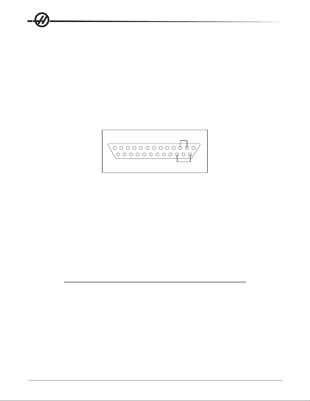
RS-232 Loop Back Test
If you have a communications problem between Port #1 of the machine and your external computer, use the
following procedure to isolate the problem to either internal or external causes.
1. Unplug the cable from Port #1 of the Control Panel, and plug the cable tester in (port #1).
PLUG TESTER
BACK VIEW
The RS-232 Plug Tester is a 25-pin male connector with the following pins shorted.
Pins 2 & 3
Pins 14 & 16
In order to properly perform the test, Setting 14 must be set to CTS/RTS.
2. If the machine is on, cycle the power (power down then turn back on).
3. Press List Prog, followed by press Param Dgnos twice, then press Send RS232.
4. If the internal serial port is working, the lower left-hand part of the screen will display Serial Passed. (This
means that the system, to the output of the control panel, is working. Check the cable to the computer
set-up if you still have a communications problem.)
If the internal serial port is bad, the lower left-hand part of the screen will display Serial Failed. (This means
there is a problem inside the control panel, or that the test connector is unplugged or missing.)
RS-232 PCB Replacement
1. Follow all precautions noted previously before working in the electrical cabinet.
NOTE: It is necessary, when replacing the RS-232 board, to work from the inside and
outside of the cabinet at the same time.
2. On the left side of the cabinet, at the top of the side panel, are two serial port connections labeled "Serial
Port #1" and "Serial Port #2". Serial Port #1 is the upper connection.
24
Electrical Service
96-0284 rev C June 2007
Page 26
P1
SERIAL
KEYBOARD
INTERFACE
PCB
700B
VIDEO &
KEYBOARD
PCB
J13
850
J3
MICRO
PROCESSOR
PCB
* Serial interface replaces cable 700 with cable 700B.
RS-232 Wiring Diagram (with Serial Keyboar d)
P850A
P850
RS 232/ 32-4090 J1
PORT 1
Serial User’s Port
PORT 2
Aux Axis Port
3. To remove the RS-232 board, unscrew the two hex screws (on the exterior of the cabinet) holding the
connector to the cabinet. From the inside of the cabinet, pull the connector through the panel, and discon-
nect the cable.
4. Replace the RS-232 board by first connecting the appropriate cable to the board (850 to Serial Port #1,
850A to Serial Port #2, then inserting the board (cable side up) through the left side panel. Attach with the
two hex screws previously removed. Ensure the board for Serial Port #1 is the upper connector and the
board for Serial Port #2 is the lower connector.
5. Replace the Serial Keyboard Interface (SKBIF) board, using the four screws previously removed, starting at
the top right. Attach the screw and standoff loosely, then all other screws and standoffs, until all are
mounted. Tighten down completely .
6. Reconnect all cables to the Serial KBIF board at their proper locations.
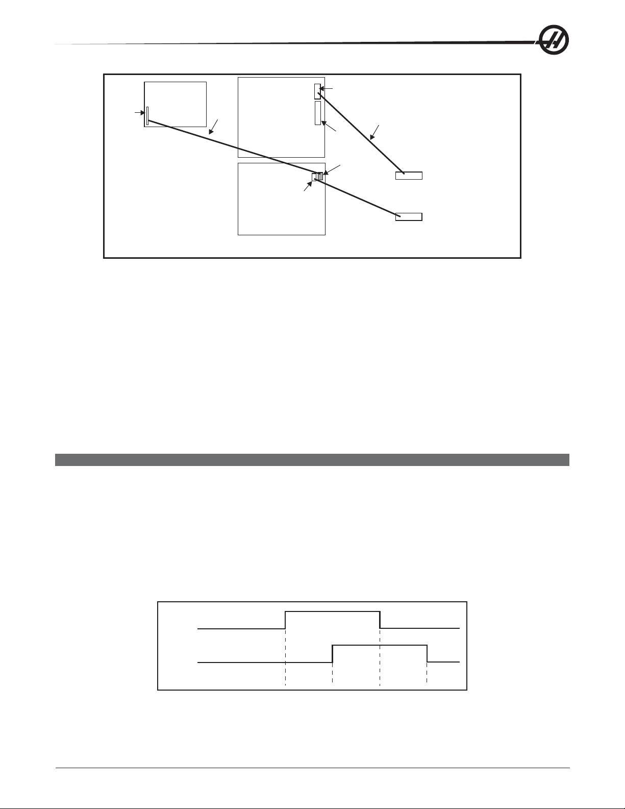
SPARE USER M CODE INTERFACE
The M code interface uses outputs M21-25 and one discrete input circuit. M codes M21 through M25 will
activate relays labeled M21-25. These relay contacts are isolated from all other circuits and may switch up to
120V AC at three amps. The relays are SPDT (Single Pole Double Throw).
WARNING!
Power circuits and inductive loads must have snubber protection.
The M-FIN circuit is a normally open circuit that is made active by bringing it to ground. The one M-FIN applies
to all of the user M codes.
The timing of a user M function must begin with all circuits inactive (open). The timing is as follows:
M21
M-FIN Discrete
Input 1009
CNC is:
Running Waiting
for M-fin
.05 ms
delay
Waiting for
end M-fin
Running
The Diagnostic Data display page may be used to observe the state of these signals.
96-0284 rev C June 2007
Electrical Service
25
Page 27
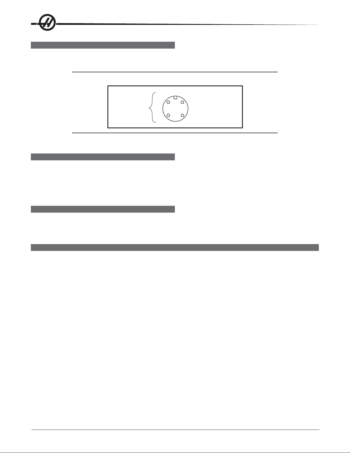
M FUNCTION RELAYS (M-FIN)
The I/O PC board has relays that are available to the user. M21 is already wired out to P12 at the side of the
control cabinet. This is a four-pin DIN connector and includes the M-FIN signal.
NOTE: Refer to Diagnostic Data for specific machine Inputs and Outputs.
3
M-Code
Output Relay
Normally Open
4
NOTE: Some or all of the M21-25 on the I/O PCB may be used for factory installed
options. Inspect the relays for existing wires to determine which are in use.
1 M-FIN, Input Signal
2 Input GND
M-FIN DISCRETE INPUT
The M-FIN discrete input is a low voltage circuit. When the circuit is open, there is +12V DC at this signal.
When the line is brought to ground, there is about 10 milliamps of current. M-FIN is discrete input 1009 and is
wired from input 1009 on the I/O PCB (usually P10). The return line for grounding the circuit should come from
that PCB. For reliability, these two wires should be routed in a shielded cable where the shield is grounded at
one end only. The diagnostic display shows a “1” when the circuit is open and a “0” when it is grounded.
WIRING THE RELAYS
Relays are marked on the I/O PCB, with their respective terminals forward of them. If the optional 8M relay
board is installed, connections on the I/O PCB are unused, since they are replaced by relays on the optional
board. Refer to the figure, and the Probe Option figure in the Electrical Diagrams section for terminal labeling.
SWITCHES
X, Y, Z Travel Limit Switches
Machine zero position is defined by a limit switch for each of the X, Y, and Z axes. After the search for machine
zero is complete, these switches are used to limit travel in the positive direction. Travel in the negative direction
is limited by stored stroke limits. It is not normally possible to command the servo axes past the machine zero
as servo travel lookahead will decelerate and stop each motor prior to exceeding the stroke limits.
Prior to performing a Power Up/Restart or an Auto All Axes operation, there are no travel limits. You can jog into
the hard stops in either direction for X, Y, or Z. After a Zero Return has been performed, the travel limits will
operate unless an axis hits the limit switch. When the limit switch is hit, the zero returned condition is reset
and an Auto All Axes must be done again to ensure you can still move the servo back away from it.
The limit switches are normally closed. When a search for zero operation is being performed, the X, Y, and Z
axes will move towards the limit switch unless it is already active (open); then move away from the switch until
it closes again; then continue to move until the encoder Z channel is found. This position is machine zero.
On some mills, the auto search for zero in the Z-axis is followed by a rapid move from the limit switch position
down to the tool change position, making the Z-axis a little different from the other axes. The position found
with the limit switch is not machine zero but is the position used to pull tools out of the spindle. Machine zero
for Z is below this by Parameter 64. Be careful during the Z zero search and stay clear of that rapid move.
What Can Go Wrong With Switches?
Proximity switches are distance sensitive, and must be set no farther than .012” (3mm) away from an assembly or limit flag. An improperly set proximity switch will give inconsistence results, which may be interrupted as
another problem. Any time a switch is replaced ensure the proper distance is set.
26
Electrical Service
96-0284 rev C June 2007
Page 28

If the machine is operated with Limit Switch inputs disabled, a Low Lube and Door Open alarm is generated. In
addition, Home search will not stop at the limit switch and instead runs into the physical stops on each axis.
If the switch is damaged and permanently open, the zero search for that axis will move in the negative direction
at about 0.5 in/min until it reaches the physical travel stops at the opposite end of travel.
If the switch is damaged and permanently closed, the zero search for that axis will move at about 10 in/min in
the positive direction until it reaches the physical stops.
If the switch opens or a wire breaks after the zero search completes, an alarm is generated, the servos are
turned off, and all motion stops. The control will operate as though the zero search was never performed. Reset
can be used to turn servos on, but you can jog that axis slowly .
Clamp/Unclamp Switches
There are two switches used to sense the position of the turret or tool clamping mechanism. They are both
normally closed and one will activate at the end of travel during unclamping and the other during clamping.
When both switches are closed, it indicates that the turret or drawbar is between positions.
The diagnostic display can be used to display the status of the relay outputs and the switch inputs.
Door Hold Switch
The switch is normally closed. When the door opens, the switch opens and the machine stops with a “Door
Hold” function. When the door is closed again, operation continues normally.
If the door is open, it is not possible to start a program. Door hold will not stop a tool change operation, will not
turn off the spindle, and will not turn off the coolant pump. The door hold function can be temporarily disabled
with Setting 51, but this setting will return to Off when the control is turned off.
Tool #1 Sense Switch
The tool rotation turret has a switch that is activated when tool one is in position or facing toward the spindle.
At Power On this switch can indicate that tool #1 is in the spindle. If this switch is not active at power-on, the
first tool change will rotate the turret until the switch engages and then move to the selected tool. The diagnos-
tic display will show the status of this input switch as “Tool #1”. A “1” indicates that tool #1 is in position.
Umbrella Tool Changer Geneva Wheel Position Mark (Vert)
The turret rotation mechanism has a switch mounted so that it is activated for about 30o of travel of the Geneva
mechanism. When activated, this switch indicates that the turret is centered on a tool position. This switch is
normally closed. The diagnostic display will show this status of this input switch as “TC MRK”. A “1” indicates
the Geneva wheel is in position.
Umbrella Tool Changer Shuttle In/Out Switches (Vert)
Two switches are used to sense the position of the tool changer shuttle and the arm that moves it. One switch
is activated when the shuttle is moved to full travel inward and one is activated when it is in full travel outward.
These switches are normally closed, so that both are closed between in and out. The diagnostic display will
show the status of the input switch. A “1” indicates the associated switch is activated or open.
Transmission High/Low Gear Position Switches
On machines with a two-speed transmission, there are two switches in the gearbox used to sense the position
of the gears. One switch indicates “High” by opening and the other indicates “Low” by opening. Between gears,
both switches are closed, indicating a between-gear condition. The diagnostic display shows the status of
these switches and the Curnt Comds display shows which gear is selected. If the switches indicate that the
gearbox is between gears, the display will indicate “No Gear”.
NOTE: The Transmission High/Low Gear Position Switches are located at the bottom
of the Gearbox Assembly and are difficult to reach. Removal of this assembly
is necessary to replace these switches. See the Mechanical Components
Service Manual, for Spindle Motor and Transmission removal.
96-0284 rev C June 2007
Electrical Service
27
Page 29

CONTROL MEMORY
The Haas processor board contains three types of memory:
• Flash Memory - stores the binary and language files (software). Information stored only changes when the
serviceperson loads a new binary file. Flash memory retains its contents even when the power is turned off.
• Random Access Memory (RAM) - When the machine is powered up the processor board copies the binary
file and the selected language text from the flash memory into RAM, which is run from there. RAM also holds
internal information that the control needs while it is running, such as current position, displays screens, etc.
When the user selects a different language, it is copied over the last language. Information stored in RAM is
not retained when the machine is turned off.
• Battery Backed-up Random Access Memory (BBU-RAM) - This type of memory uses an on-board battery
to retain its information after the machine is turned off. If battery power is low the memory gets corrupted, and if
the battery voltage goes to zero, the memory goes blank. Battery Backed up memory holds information such
as user programs, Settings, Parameters, Offsets.
Clearing Processor Memory (Coldfire):
At the prompt, >, type in the following and press, “enter” to test and clear BBU Ram:
M 6000000 60FFFFF
The following message is repeatedly displayed until Reset is pressed to stop the BBU RAM memory test:
Memory test passed, press and hold reset to stop
To clear Flash Memory (Coldfire Processor):
Type “FC” and press enter
The following message will be displayed:
ERASING FLASH – PLEASE WAIT…
FIRST FLASH CHIP ERASED
FLASH CLEAR COMPLETE
NOTE: This flash memory clear will not erase the ColdFire monitor program
Clearing the memory in a control
At times it is necessary to clear the memory of the machine. This may have to be done to update software, or
do remove corrupted software. T o do this follow the step s for the specific type of memory. The next two steps
must be followed to prepare the machine.
1. The programs, settings and other control information must be saved before clearing the memory . It may be
necessary to turn off Setting 23 to save the macro variables. The following are the files to save:
PROGRAMS (PGM) SETTINGS (SET) OFFSETS (OFS)
PARAMETERS (PAR) MACRO VARIABLES (VAR)
Disconnect the RS-232 cables, if used.
2. Turn off the machine and then turn it back on while holding the PRGRM CONVRS button. The display will be
similar to the following:
HAAS 68030 MONITOR ddd-mmm-yy
FLASH MEMORY FOUND: 1024K @ 00080000
BBU RAM FOUND: 1024 K (1024K of BBU-RAM)
68882 COPROCESSOR NOT FOUND
This example shows 1024K of flash memory at address 80000 and 1024K of BBU-RAM. Write down what the
machine has before continuing.
28
Electrical Service
96-0284 rev C June 2007
Page 30

Clearing the BBU-RAM (68K Processor)
1. Type in “M 3000D6C 300FFFF” and press Enter. The control responds with “Memory Test Passed” written
several times. The command “M3000D6C” checks and clears just a portion of the BBU-RAM. It avoids the
section that contains the serial number of the machine (Setting 26). Most problems can be solved without
removing the serial number .
2. Press and Hold Reset until you see “>” displayed. If the “>” does not display, continue to step 3.
3. This step will clear the BBU-RAM completely including the machine serial number. Use the following to
determine the command to clear BBU-RAM.
BBU RAM Found Board Size Command to Clear BBU-RAM
256K 256K M 3000000 303FFFF
1024K 1 megabyte M 3000000 30FFFFF
4096K 4 megabyte M 3000000 33FFFFF
8192K 8 megabyte M 3000000 37FFFFF
16384K 16 megabyte M 3000000 3FFFFFF
To Clear BBU- RAM as per the example, Type the following and press Enter:
M 3000000 30FFFFF (for 1024K)
Clearing Flash Memory:
Clearing Flash Memory will solve problems caused by fragments of code left behind from previous binary or
language files. The most common problem is BAD LANGUAGE VERSION alarm. To clear the flash memory, a
value is entered to tell the system where it is located. Following these steps will clear the memory or give you
the message, “Undefined Command”, or a similar message.
If the control displayed the amount of flash memory in step 2 of “Clearing the memory in the control”, then do
one of the following depending upon how much flash Memory is found:
Enter FC 80000 200000 and press enter (for 1536K of FLASH)
Enter FC 80000 280000 and press enter (for 2048K of FLASH)
Enter FC 80000 380000 and press enter (for 3072K of FLASH)
Enter FC 8000 and press enter (for 0.5MB of FLASH)
Enter FC 100000 and press enter (for 1.0MB of FLASH)
Enter FC 180000 and press enter (for 1.5MB of FLASH)
If you get the message “Undefined Command” (or similar) perform the following steps.
Enter FC 8000 FFFFF and press enter (to clear 80000 thru FFFFF)
Enter FC 100000 17FFFF and press enter (to clear 100000 thru 17FFFF)
Enter FC 180000 1FFFFF and press enter (to clear 180000 thru 1FFFFF)
The flash memory is now cleared and software must be loaded to continue.
If the control is prior to 1997, 512K x 8 bit RAM chips are used on the processor PCB. These can be cleared
as follows:
Enter the following for 4 chips: FC 20000 9FFFF and press enter
Enter the following for 5 chips: FC 20000 BFFFF and press enter
Enter the following for 6 chips: FC 20000 DFFFF and press enter
Enter the following for 7 chips: FC 20000 FFFFF and press enter
The flash memory is now cleared and software must be loaded to continue.
96-0284 rev C June 2007
Electrical Service
29
Page 31

DIAGNOSTIC DATA
The Alarm Msgs display is the most important source of diagnostic data. At any time after the machine
completes its power-up sequence, it will either perform a requested function or stop with an alarm. Refer to the
Alarms chapter for their possible causes and some corrective action.
If there is an electronics problem, the controller may not complete the power-up sequence and the monitor will
remain blank. In this case, there are two sources of diagnostic data; these are the audible beeper and the
LEDs on the processor PCB. If the audible beeper is alternating a ½ second beep, there is a problem with the
main control program stored in EPROMs on the processor PCB. If any of the processor electronics cannot be
accessed correctly, the LEDs on the processor PCB will or will not be lit.
If the machine powers up but has a fault in one of its power supplies, it may not be possible to flag an alarm
condition. If this happens, all motors will be kept off and the top left corner of the monitor will display a Power
Failure Alarm message, and all other functions of the control will be locked out.
When the machine is operating normally, a second push of the Param/Dgnos key will select the diagnostics
display page. The Page Up and Page Down keys are then used to select one of two different displays. These
are for diagnostic purposes only and the user will not normally need them. The diagnostic data consists of 32
discrete input signals, 32 discrete output relays and several internal control signals. Each can have the value of
0 or 1. In addition, there are up to three analog data displays and an optional spindle rpm display . Their number
and functions follow.
DISCRETE INPUTS/OUTPUTS (LATHE)
Discrete Inputs
# Name # Name
1000 Tool Turret Unlock 1016 Spare
1001 Tool Turret Lock 1017 Spare
1002 Spare 1018 Spare
1003 Low Coolant 1019 Spare
1004 Automatic Door 1020 Low hyd pressure
1005 Spindle In Hi Gear 1021 T.S. Foot Switch
1006 Spindle In Low Gear 1022 Probe Not Home
1007 Emergency Stop 1023 Spare 2b
1008 Door Switch 1024 Tool Unclamp Rmt*
1009 M Code Finish 1025 Low Phasing 115V
1010 Over Voltage 1026 B F End of Bar
1011 Low Air Pressure 1027 Bar Feeder Fault
1012 Low Lube Press. 1028 Ground Fault
1013 Regen Overheat 1029 G31 Block Skip
1014 Spare 1030 B F Spindle Intlk
1015 Spare 1031 Conveyr Overcrnts
30
Electrical Service
96-0284 rev C June 2007
Page 32

Discrete Outputs
# Name # Name
1100 Hyd Pump Enable 1116 Move Spigot CW
1101 Spare 1117 Move Spigot CCW
1102 Spare 1118 Pal Ready Light
1103 Spare 1119 T.S. High Pressure
1104 Spindle Brake 1120 Tool Turret Out
1105 Coolant Pump on 1121 T.S. Reverse
1106 Power Off 1122 T.S. Forward
1107 Way Lube Pump 1123 (CE) Door Locked
1108 SB Motor Load PR 1124 M21 (Auto Door Clutch)
1109 SB Motor Load Bar 1125 M22 (Parts Catcher)
1110 Auto Door Open 1126 M23 (C Axis Engage)
1111 Auto Door Close 1127 HPC Coolant
1112 Spindle Hi Gear 1128 Green Beacon On
1113 Spindle Low Gear 1129 Red Beacon On
1114 Unclamp Chuck 1130 Enable Conveyor
1115 Lock Spindle 1131 Reverse Conveyor
The second page of diagnostic data is displayed using the Page Up and Page Down keys. It contains:
Inputs 2
X-axis Z Channel X Motor Over Heat
Y-Axis Z Channel Y Motor Over Heat
Z-axis Z Channel Z Motor Over Heat
A-axis Z Channel A Motor Over Heat
B-axis Z Channel B Motor Over Heat
C-axis Z Channel C Motor Over Heat
X Home Switch X drive fault
Y Home Switch Y drive fault
Z Home Switch Z drive fault
A Home Switch A drive fault
B Home Switch B drive fault
C Home Switch C drive fault
X Cable Input S Z CH Spindle Z Channel
Y Cable Input
Z Cable Input
A Cable Input
B Cable Input
C Cable Input
The Temp-Track option displays the X and Z ballscrew temperatures on the Inputs2 diagnostics screen just
above “SP Load” when Parameter 266 or 268 bit 9 “Temp Sensor” is set to 1. The following inputs and outputs
pertain to the Haas Vector Drive. If it is not enabled, a value of * is displayed. Otherwise, it displays a 1 or 0.
Haas Vector Drive
Name Name
Spindle Forward Spindle Fault
Spindle Reverse Spindle Locked
Spindle Lock Spindle Cable Fault
Spindle At Speed Spindle Overheat
Spindle Stopped
96-0284 rev C June 2007
Electrical Service
31
Page 33

Analog Data
Name Description
SP LOAD Spindle load in %
SP SPEED Spindle rpm CW or CCW
RUN TIME Total machine run time
TOOL CHANGES Number of tool changes
VER X.XXX Software version number
YY/MM/DD Today's date
MDL SL-__ Model number
DC BUSS Mocon II
DISCRETE INPUTS/OUTPUTS (MILLS)
# Name # Discrete Input Name
1000 TC Changer In/SMTC Pocket Down 1023 Spare 3/APC Pin Clr #2
1001 TC Changer Out/SMTC Pocket Up 1024 Tool Unclmp Rmt*
1002 Tool One In Pos. 1025 Spare
1003 Low TSC Pressure 1026 Spare 3A/APC Pal #2 Home
1004 Tool In Position 1027 Spare 3B/APC Pal #1 Home
1005 Spindle High Gear 1028 Ground Fault
1006 Spindle Low Gear 1029 G31 Block Skip
1007 Emergency Stop 1030 Spigot Position
1008 Door Safety Switch 1031 Conveyr Overcrnt
1009 M Code Finish*/APC: APC Pal Clamp 1032 Spare 4A
1010 Over Voltage (Mini-Mill - P.S. Fault) 1033 Spare 4B
1011 Low Air Pressure 1034 Spare 5A
1012 Low Lube Press. 1035 Spare 5B
1013 Regen Over Heat 1036 Spare 6A
1014 Drawbar Open 1037 Spare 6B
1015 Drawbar Closed 1038 Spare 7A
1016 Spare 1039 Spare 7B
1017 Spare 1040 Spare 8A
1018 Spare 1041 Spare 8B
1019 Spare 1042 Spare 9A (SMTC: Motor stop)
1020 Low Trans Oil Prs 1043 Spare 9B (SMTC: Origin)
1021 Spare 1/APC Door 1044 Spare 10A (SMTC: Clamp / Unclamp)
1022 Spare 2/APC Pin Clr #1 1045 Spare 10B
The inputs are numbered the same as the connections on the inputs printed circuit board. (*): active when = 0.
32
Electrical Service
96-0284 rev C June 2007
Page 34

# Discrete Output Name # Discrete Output Name
1100 Powered Servos 1120 Unclamp Pre-Chrg
1101 Spare 1121 HTC Shuttle Out
(Air Drive Shuttle in/ APC Door)
1102 Spare 1122 Brake 5TH Axis
1103 Spare 1123 CE Door Lock
1104 Brake 4th Axis 1124 M21
1105 Coolant Pump On 1125 M22
1106 Auto Power Off 1126 M23 (Air Drive Shuttle: Move Shuttle Out)
1107 Spind. Motor Fan 1127 TSC Coolant
1108 Move T.C. In/APC Chain Dr Fwd 1128 Green Beacon On
1109 Move T.C. Out/APC Chain Dr Rev 1129 Red Beacon On
1110 Rotate T.C. CW 1130 Enable Conveyor
1111 Rotate T.C. CCW 1131 Reverse Conveyor
1112 Spindle Hi Gear 1132 M-fin
1113 Spindle Low Gear 1133 Probe
1114 Unclamp Tool 1134 spare
1115 Spare 1135 spare
1116 Move Spigot CW 1136 spare
1117 Move Spigot CCW 1137 spare
1118 Pal Ready Light 1138 spare
1119 TSC Purge 1139 spare
NOTE: The following inputs and outputs change for machines equipped with an APC.
# Discrete Output Name # Discrete Output Name
1021 APC CE Door 1108 APC Chain Drive Forward
1022 APC Pin CLR #1 1109 APC Chain Drive Reverse
1023 APC Pin CLR #2 1121 PAL Clamp
1026 APC PAL #2 Home 1122 Door
1027 APC PAL #1 Home 1125 APC Motor
1046 APC Door Closed 1126 Beeper
1047 Door Open 1137 APC Chain Drive Power Enable
1048 APC Pallet Clamped 1138 Air Blast
1101 Pallet Clamped 1139 APC Beeper
The second page of diagnostic data is displayed using the Page Up and Page Down keys. It contains:
Inputs 2
Name Name Name
X Axis Z Channel X Overheat X Cable Input
Y Axis Z Channel Y Overheat Y Cable Input
Z Axis Z Channel Z Overheat Z Cable Input
A Axis Z Channel A Overheat A Cable Input
B Axis Z Channel B Overheat B Cable Input
X Home Switch X Drive Fault Spindle Z Channel
Y Home Switch Y Drive Fault
Z Home Switch Z Drive Fault
A Home Switch A Drive Fault
B Home Switch B Drive Fault
96-0284 rev C June 2007
Electrical Service
33
Page 35

The following inputs and outputs pertain to the Haas Vector Drive. If it is not enabled, these will display a value
of *. Otherwise, it will display a 1 or 0.
Spindle Forward
Spindle Reverse
Spindle Lock
Spindle at Speed*
Spindle Stopped
Spindle Fault
Spindle Locked
Spindle Cable Fault
Spindle Over Heat
The following Discrete Inputs/Outputs 2 are available when Parameter 278 SMNT bit 1,2 or 3 (Side-Mount Tool
Changer) is set and Parameter 209 MCD RLY BRD (M-Code relay board) is On.
Discrete Inputs 2
Name Name
Spare Input 4A Spare Input 8A
Spare Input 4B Serp. Shot Pin*
Spare Input 5A Motor Stop
Spare Input 5B Origin
Spare Input 6A Clamp/Unclamp
Spare Input 6B Serp. Cam Count
Spare Input 7A Spare Input 11A
Spare Input 7B Spare Input 11 B
Discrete Outputs 2
Name Name
Spare Output 32 Spare Output 44
Spare Output 33 Spare Output 45
Spare Output 34 Spare Output 46
Spare Output 35 Spare Output 47
Spare Output 36 Spare Output 48 (SMTC: Serp. ATC Enable)
TC MTR SW Spare Output 49 (SMTC: Serp. ATC Rev.)
Spare Output 38 Spare Output 50 (SMTC: Serp. Carsl CW)
Spare Output 39 Spare Output 51 (SMTC: Serp. Carsl CCW)
Spare Output 40 Spare Output 52 (SMTC: Serp. Carsl Ena.)
Spare Output 41 Spare Output 53
Spare Output 42 Spare Output 54
Spare Output 43 Spare Output 55
Analog Data
Name Description
DC BUSS Voltage from Haas Vector Drive (if equipped)
uP TEMP Displayed when Parameter 278 bit "µP Encl Temp" is set to 1)
SP LOAD Spindle load in %
SP SPEED Spindle rpm CW or CCW
RUN TIME Machine total run time
TOOL CHANGES Number of tool changes
VER X.XXX Software version number
MOCON MOCON software version
YY/MM/DD Today's date
MDL HS__ Machine model
FV 2 11.0004 Floppy version (Ethernet Firmware)
34
Electrical Service
96-0284 rev C June 2007
Page 36

CABLE LIST
WIRE/
TERMINAL FUNCTION NAME:
NUMBER
INCOMING POWER 195-260 VAC (353-488 VAC OPTIONAL)
L1 INCOMING 195-260VAC, PHASE 1, TO CB1-1
L2 INCOMING 195-260VAC, PHASE 2, TO CB1-2
L3 INCOMING 195-260VAC, PHASE 3, TO CB1-3
71 PROTECTED 195-260 VAC FROM MAIN CB1-4 TO K1-1
72 PROTECTED 195-260 VAC FROM MAIN CB1-5 TO K1-2
73 PROTECTED 195-260 VAC FROM MAIN CB1-6 TO K1-3
74 195-260 VAC FROM K1-4 TO XFORMER T1
75 195-260 VAC FROM K1-5 TO XFORMER T1
76 195-260 VAC FROM K1-6 TO XFORMER T1
77 230VAC PHASE 1 , FROM XFORMER T1 TO VECTOR/CHIP CONV
78 230VAC PHASE 2 , FROM XFORMER T1 TO VECTOR/CHIP CONV
79 230VAC PHASE 3 , FROM XFORMER T1 TO VECTOR/CHIP CONV
90 115 VAC FROM TB2 (CB2 OUTPUT) TO IOPCB P33
91 STEPPED-DOWN 115 VAC (FROM XFRMR T1)
92 STEPPED-DOWN 115 VAC (FROM XFRMR T1)
93 STEPPED-DOWN 115 VAC (FROM XFRMR T1)
94 SHIELD DRAIN
—- 115 VAC FROM XFORMER T1 TO TB1
94 STEPPED-DOWN 115 VAC (FROM XFRMR T1)
95 STEPPED-DOWN 115 VAC (FROM XFRMR T1)
96 STEPPED-DOWN 115 VAC (FROM XFRMR T1)
90A 115 VAC TO CRT
91A LEG 1
92A LEG 2
93A SHIELD DRAIN
90B 115 VAC TO HEAT EXCHANGER (CABINET DOOR FAN)
91B LEG 1
92B LEG 2
93B SHIELD DRAIN
90C 115 VAC TO CB4
91C LEG 1
92C LEG 2
93C SHIELD DRAIN
10 0 M-FIN
10 1 SIGNAL
102 COMMON
103 SHIELD DRAIN
100A MFIN OUTPUT M21 (MCD RELAY BOARD M21)
101A UNSWITCHED LEG 1
102A SWITCHED LEG 2
103A SHIELD DRAIN
110 SPARE
96-0284 rev C June 2007
Cable List
35
Page 37

120 TSC OVER TEMP THERMAL SENSOR (Vert)
121 THERMAL SENSOR SIGNAL
122 THERMAL SENSOR RETURN
123 SHIELD
140 230VAC 3PH POWER TO CHIP CONVEYOR MOTOR
141 PHASE A 230VAC
142 PHASE B 230VAC
143 PHASE C 230VAC
144 STARTING WINDING 230VAC
145 STARTING WINDING 230VAC
146 SHIELD DRAIN
140A 230VAC 3PH POWER IN CONDUIT TO CHIP CONVEYOR (Lathe)
141A PHASE A 230VAC
142B PHASE B 230VAC
143B PHASE C 230VAC
160 3PH 230VAC TO CHIP CONVEYOR CONTROLLER
161 PHASE A 230VAC
162 PHASE B 230VAC
163 PHASE C 230VAC
164 SHIELD DRAIN
170 AUTO OFF FUNCTION
171 UNSWITCHED LEG 1
172 SWITCHED LEG 2
173 SHIELD DRAIN
180 COOLANT SPIGOT DETENT SWITCH (Mill) SPARE (Lathe & Horiz)
18 1 SIGNAL
182 COMMON
183 SHIELD DRAIN
190 UNCLAMP FROM SPINDLE HEAD TO IOASM
191 INPUT 25
192 DIGITAL RETURN
193 SHIELD DRAIN
200 COOLANT SPIGOT MOTOR (12VDC) (Mill) SPARE (Lathe & Horiz)
201 MOTOR +
202 MOTOR -
210 DATA CABLE TO 3" FLOPPY DISK DRIVE
220 SERVO BRAKE 115VAC (Mill)
221 115VAC COMMON
222 115VAC SWITCHED
223 SHIELD DRAIN
230 5’th AXIS BRAKE (Vert & Horiz) TAILSTOCK FORWARD OPTION (Lathe)
231 115VAC COMMON
232 115VAC SWITCHED
233 SHIELD DRAIN
240 PALLETS UP & DOWN INPUTS (Vert & Horiz) BARFEEDER LOAD BAR-BARFEEDER LOAD Q (Lathe)
241 PALLETS UP (Vert & Horiz) END OF BAR (Lathe)
242 PALLETS DOWN (Vert & Horiz) LOADER OK (Lathe)
243 COMMON
244 SHIELD DRAIN
36
Cable List
96-0284 rev C June 2007
Page 38

250 VR SHUT IN / APC DOOR OPEN/ MD NIAGRA COOLANT ON (Vert option) HTC SHUTTLE/MORI MANUAL
TOOL RELEASE (Horiz) TAILSTOCK REVERSE OPTION (Lathe)
251 LEG 1 (Mill) 115 VAC (Lathe)
252 LEG 2 (Mill) 115 VAC RETURN (Lathe)
253 SHIELD DRAIN
260 K210 CABLING FOR EC (Mill) SPARE (Lathe)
261 SWITCHED LED
262 UNSWITCHED LEG
263 SHIELD DRAIN
270 K111 CABLING FOR EC (Mill) TAILSTOCK RAPID OPTION (Lathe)
271 UNSWITCHED LEG 1 (Mill) 115 VAC (Lathe)
272 SWITCHED LEG 2 (Mill) 115 VAC RETURN (Lathe)
273 SHIELD DRAIN
280 RED/GREEN STATUS LIGHT WIRING
281 RED LAMP 115VAC
282 GREEN LAMP 115VAC
283 COMMON 115VAC
284 SHIELD DRAIN
290 115VAC TO XFORMER T2 10VAC OUTPUT (Horiz) CABLE OP LIGHT + SPINDLE MOTOR FAN (Lathe)
291 LEG 1 PRIMARY (Horiz) 115 VAC (Lathe)
292 LEG 2 PRIMARY (Horiz) 115 VAC RETURN (Lathe)
293 CENTER TAPPED (GROUND) (Horiz) SHIELD DRAIN (Lathe)
294 LEG 1 SECONDARY (Horiz)
295 LEG 2 SECONDARY (Horiz)
300 115VAC TO SPINDLE MOTOR FAN/OIL PUMP/OILER
301 LEG 1 115VAC PROTECTED
302 LEG 2 115VAC PROTECTED
303 SHIELD DRAIN
310 APC #2 DOOR OPEN (Vert) PC PALLET CW/CCW (Horiz)
AUTO DOOR CLUTCH - PARTS CATCHER (Lathe)
330 230V 3PH FROM CB6 TO K2 (LATHE HYDRAULICS)
331 PHASE 1 230VAC
332 PHASE 2 230VAC
333 PHASE 3 230VAC
340 230V 3PH FROM K2 TO HYDRAULIC PUMP (LATHE)
341 PHASE 1 230VAC
342 PHASE 2 230VAC
343 PHASE 3 230VAC
350 SERVO BRAKE RELEASE 115VAC (Mill) 115VAC HYD PUMP ENABLE (Lathe)
351 LEG 1 COMMON (Mill) 115VAC (Lathe)
352 LEG 2 SWITCHED (Mill) 115VAC RETURN (Lathe)
353 SHIELD DRAIN
390 115VAC TO 4’TH AXIS BRAKE (LATHE PART DOOR)
391 LEG 1 COMMON
392 LEG 2 SWITCHED
393 SHIELD DRAIN
410 TOOL CHANGER DOOR/APC CE DOOR OPEN (Mill) TAILSTOCK FOOT SWITCH (Lathe)
411 SIGNAL (Lathe)
412 RETURN (Lathe)
413 SHIELD DRAIN
420 APC #2 PIN CLR #1 / APC #2 PIN CLR #2 / APC #2 PAL #2 HOME / APC #2 PAL #1 HOME (Vert)
MORI ARM IN/OUT - SMTC ARM CW/CCW (Horiz)
96-0284 rev C June 2007
Cable List
37
Page 39

430 APC PALLET CLAMP MD PAL UP (Mill) APL LIGHT/BF EXTENDED PUSH (Lathe)
440 AUTO DOOR OPEN (Vert) SMTC CAGE DOOR OPEN - MORI ARM OUT (Horiz) DOOR OPEN (Lathe)
450 APC #2 CE DOOR OPEN (Vert) MORI ARM CW/CCW (Horiz) STEADY REST FOOT SWITCH (Lathe)
460 APC #2 DOOR CLOSED - APC #2 DOOR OPEN (Vert) MORI SLIDE 1/2 WAY - MORI SLIDE LEFT (Horiz)
APL ROTOR MARK - APL ROTOR HOME (Lathe)
470 SMTC MOTOR STOP (Vert) SMTC SHUTTLE MARK (Horiz)
490 ALL BRUSHLESS AXIS SERVO MOTOR DRIVE POWER CABLE
49 1 A PHASE
492 B PHASE
493 C PHASE
494 GROUND
490A A AXIS MOTOR POWER (Vert) 320VDC FROM SPINDLE DRIVE TO AMPLIFIERS (Horiz & Lathe)
490B B AXIS MOTOR POWER (Vert) 320VDC FROM AMPLIFIER TO SERVO POWER SUPPLY (Horiz & Lathe)
490X X AXIS MOTOR POWER
490Y Y AXIS MOTOR POWER
490Z Z AXIS MOTOR POWER
491A HIGH VOLT P1/+ RED (Horiz & Lathe)
492A HIGH VOLT N/- BLACK (Horiz & Lathe)
493A SHIELD DRAIN
491B HIGH VOLT + RED (Horiz & Lathe)
492B HIGH VOLT - BLACK (Horiz & Lathe)
500 OVERTEMP SENSOR FROM SPINDLE MOTOR
501 OVERTEMP WIRE 1
502 OVERTEMP WIRE 2
503 SHIELD DRAIN
510 RELAY CARD 1 DRIVE CABLE - 16 WIRE RIBBON
520 RELAY CARD 2 DRIVE CABLE - 16 WIRE RIBBON
530 RELAY CARD 3 DRIVE CABLE - 16 WIRE RIBBON
540 RELAY CARD 4 DRIVE CABLE - 16 WIRE RIBBON
550 INPUTS CARD CABLE (MOCON P10) 34 WIRE RIBBON
570 LOW VOLTAGE BRUSHLESS AMPLIFIER POWER CABLE ASSEMBLY (Horiz & Lathe)
571 +12VDC #22
57 2 COMMON
573 - 12VDC #22
610 X AXIS HAAS AMPLIFIER CABLE TO MOTOR CONTROLLER BOARD
610-1 +A CHANNEL
610-2 ANALOG GROUND
610-3 +B CHANNEL
610-4 ANALOG GROUND
610-5 ENABLE
610-6 LOGIC GROUND
610-7 FAULT
610-8 LOGIC GROUND
610-9 NOT USED
610-10 SHIELD/ANALOG GROUND
620 Y AXIS HAAS AMPLIFIER CABLE TO MOTOR CONTROLLER BOARD
(SAME AS 610-1 THRU 610-10) (Mill)
630 Z AXIS HAAS AMPLIFIER CABLE TO MOTOR CONTROLLER BOARD
(SAME AS 610-1 THRU 610-10)
38
Cable List
96-0284 rev C June 2007
Page 40

640 A AXIS HAAS AMPLIFIER CABLE TO MOTOR CONTROLLER BOARD
(SAME AS 610-1 THRU 610-10) (Lathe)
640A A AXIS HAAS AMPLIFIER CABLE TO MOTOR CONTROLLER BOARD
(SAME AS 610-1 THRU 610-10) (Mill)
640B B AXIS HAAS AMPLIFIER CABLE TO MOTOR CONTROLLER BOARD
(SAME AS 610-1 THRU 610-10) (Mill)
640C C AXIS HAAS VECTOR CURRENT COMMAND CABLE TO MOTOR CONTROLLER BD.
(SAME AS 610-1 THRU 610-10) (Vert)
640C HAAS VECTOR DRIVE CURRENT COMMAND CABLE (Horiz & Lathe)
640C-1 A PHASE
640C-2 B PHASE
640C-3 ENABLE
640C-4 FAULT
640C-5 320VDC VOLTAGE MONITOR
640C-6 A PHASE RETURN
640C-7 B PHASE RETURN
640C-8 DIGITAL GROUND
640C-9 FAULT RETURN
640C-10 ANALOG GROUND
650 THREE PHASE POWER TO SPINDLE MOTOR
651 LEG 1 OF 230VAC
652 LEG 2
653 LEG 3
654 SHIELD DRAIN
650A THREE PHASE POWER TO SPINDLE MOTOR
651A LEG 1 OF 230VAC
652A LEG 2
653A LEG 3
654A SHIELD DRAIN
650B THREE PHASE POWER TO SPINDLE MOTOR
651B LEG 1 OF 230VAC
652B LEG 2
653B LEG 3
654B SHIELD DRAIN
660 X-AXIS ENCODER CABLE
660-1 LOGIC RETURN (D GROUND)
660-2 ENCODER A CHANNEL
660-3 ENCODER B CHANNEL
660-4 +5 VDC
660-5 ENCODER Z CHANNEL (OR C)
660-6 HOME/LIMIT SW
660-7 OVERHEAT SWITCH
660-8 ENCODER A*
660-9 ENCODER B*
660-10 ENCODER Z* (OR C*)
660-11 X HALL A (NOT USED)
660-12 X HALL B (NOT USED)
660-13 X HALL C (NOT USED)
660-14 X HALL D (NOT USED)
660-15 SHIELD DRAIN
660-16 (NOT USED)
670 Y-AXIS ENCODER CABLE (SAME AS 660-1 THRU 660-16) (Mill)
680 Z-AXIS ENCODER CABLE (SAME AS 660-1 THRU 660-16)
96-0284 rev C June 2007
Cable List
39
Page 41

690 A-AXIS ENCODER CABLE (SAME AS 660-1 THRU 660-16) (Vert & Lathe)
690A A-AXIS ENCODER CABLE (SAME AS 660-1 THRU 660-16) (Horiz)
690B B-AXIS ENCODER CABLE (SAME AS 660-1 THRU 660-16) (Mill)
690C C-AXIS ENCODER CABLE (SAME AS 660-1 THRU 660-16) (Mill)
700 KEYBOARD CABLE - 34 WIRE RIBBON WITH IDC (FROM VIDEO P4 TO KBIF P1)
710 APC #1 PALLET READY 1 / APC #1 PALLET READY 2 (Vert)
P-COOL/BF COLLET OPEN - BF COLLET CLOSE (Horiz) APL GRIP 1,2 (Lathe
711 FORWARD COMMAND (Vert)
712 REVERSE COMMAND (Vert)
713 RESET COMMAND (Vert)
71 4 COMMON (Vert)
715 SHIELD DRAIN
720 ANALOG SIGNAL FROM MOCON TO SPINDLE DRIVE TO LOAD METER (BRUSH SYSTEMS)
721 0 TO +10 VOLTS SPEED COMMAND (SPINDLE DRIVE CN1-1)
722 SPEED COMMAND REFERENCE (A GROUND) (CN1-17)
723 SHIELD DRAIN
730 POWER METER FROM SPINDLE DRIVE TO KBIF (Vert) (BRUSH SYSTEMS)
731 METER +
732 METER 733 SHIELD DRAIN
730A POWER METER FROM KBIF TO METER (Vert) (BRUSH SYSTEMS)
733 METER + AFTER TRIM POT
734 METER - AFTER TRIM POT
734 METER - AFTER TRIM POT
730B ANALOG SIGNAL FROM SPINDLE DRIVE LOAD MONITOR (Vert) (BRUSH SYSTEMS)
731 SIGNAL 0.5V
732 GROUND
740 POWER ON/OFF CABLE TO FRONT PANEL
741 POWER ON SWITCH LEG 1 (24 VAC)
742 POWER ON SWITCH LEG 2 #24 N.O.
743 POWER OFF SWITCH LEG 1 (24 VAC)
744 POWER OFF SWITCH LEG 2 #24 N.C.
745 SHIELD DRAIN
750 JOG-CRANK DATA CABLE (REM JOG SIDE CONNECTION)
750-1 LOGIC RETURN (D GROUND) 0VDC
750-2 ENCODER A CHANNEL
750-3 ENCODER B CHANNEL
750-4 +5 VDC
750-5 NC (Vert) JUMPER TO 750-1 (0 VDC) (Horiz & Lathe)
750-6 X-AXIS
750-7 Y-AXIS
750-8 N/C (Vert) ENCODER A* CHANNEL (Horiz & Lathe)
750-9 N/C (Vert) ENCODER B* CHANNEL (Horiz & Lathe)
750-10 N/C (Vert) JUMPER TO 750-4 (+5 VDC) (Horiz & Lathe)
750-11 Z-AXIS
750-12 A-AXIS
750-13 X 10
750-14 X 1
750-15 SHIELD DRAIN
750-16 N/C (Vert) NOT USED (Horiz & Lathe)
40
Cable List
96-0284 rev C June 2007
Page 42

750A JOG HANDLE DATA CABLE (Horiz & Lathe)
751A +5 VDC
752A 0 VDC
753A ENCODER A CHANNEL
754A ENCODER B CHANNEL
755A SHIELD DRAIN
750B JOG HANDLE DATA CABLE (Horiz)
750B-1 +5 VDC JOG HANDLE
750B-2 0VDC
750B-3 JOG HANDLE A CHANNEL
750B-4 JOG HANDLE A* CHANNEL
750B-5 JOG HANDLE B CHANNEL
750B-6 JOG HANDLE B* CHANNEL
760 MONITOR VIDEO DATA CABLE (FROM VIDEO P3 TO CRT)
770 EMERGENCY STOP INPUT CABLE
771 SIGNAL (INPUT 8)
772 RETURN (D GROUND) (65)
773 SHIELD DRAIN
770A SECOND E-STOP INPUT / COUNTERBALANCE (Horiz) / BARFEEDER OPTION (Lathe)
771A SIGNAL
772A RETURN (D GROUND)
773A SHIELD DRAIN
770B THIRD E-STOP INPUT FOR APC (REMOTE CONTROL PANEL) (Vert)
790 APC PIN CLR #1 / MD OP DOOR OPEN - APC PIN CLR #2 / MD OP DOOR CLOSED (Vert)
PALLET CHANGER CW/CCW (Horiz) SPARE INPUTS PROBE HOME OPTION (Lathe)
791 SPARE 1 (Vert & Lathe) PALLET CW (Horiz)
792 SPARE 2 (Vert & Lathe) PALLET CCW (Horiz)
793 COMMON
794 SHIELD DRAIN
800 10VAC TO PALLET READY LAMP (Horiz)
801 UNSWITCHED LEG 1
802 SWITCHED LEG 2
803 SHIELD DRAIN
800A LAMP SWITCH JUMPER (Horiz)
801A JUMPER TO 802A
802A JUMPER TO 801A
810 TOOL CHANGER MOTORS
811 TURRET MOTOR + (IO P30-2 TO P6-J)
812 TURRET MOTOR - (IO P30-1 TO P6-I)
813 SHIELD DRAIN
810A TOOL CHANGER MOTORS
811A SHUTTLE MOTOR +
812A SHUTTLE MOTOR 813A SHIELD DRAIN
820 TOOL CHANGER STATUS
821 LOGIC RETURN (Vert) TOOL CHANGER IN (Horiz) TURRET UNCLAMPED (Lathe)
822 GENEVA MARK (INPUT 5 TO P6-G) (Vert) TOOL CHANGER OUT (Horiz) TURRET CLAMPED (Lathe)
823 TOOL #1 (INPUT 3 TO P6-E) (Vert) MAIN DRAWBAR UP (Horiz) UNUSED (Lathe)
824 SHUTTLE IN (INPUT 1 TO P6-C) (Vert) MAIN DRAWBAR DOWN (Horiz) PART LOAD (Lathe)
825 SHUTTLE OUT (INPUT 2 TO P6-D) (Vert) COMMON (Horiz & Lathe)
826 SHIELD DRAIN
96-0284 rev C June 2007
Cable List
41
Page 43

830 OVERHEAT THERMOSTAT
831 OVERHEAT SIGNAL (INPUT 14)
832 OVERHEAT RETURN (D GROUND) (65)
833 SHIELD DRAIN
840 CIRCUIT BREAKER FOR 160 VDC (Vert)
841 LEG 1 (TO 81)
842 LEG 2
843 SHIELD DRAIN
850 SERIAL PORT #1 TO SERIAL KEYBOARD INTERFACE CABLE
850A SERIAL PORT #2 INTERFACE CABLE - AUXILIARY PORT TO ROTARY CONTROLLER
860 +12V/+5V/Gnd POWER CABLES (Vert) +5V/+12V/-12V/Gnd FROM MAIN POWER SUPPLY (Horiz & Lathe)
861 +12 VOLTS (Vert) +5 VOLTS (Horiz & Lathe)
862 -12 VOLTS FROM LOW V SUPPLY TO 68020 PCB (Vert) LOGIC POWER RETURN (Horiz & Lathe)
863 +5 VOLTS (Vert) LOGIC POWER RETURN (Horiz & Lathe)
864 -5 VOLTS (Vert) +12 VOLTS (Horiz & Lathe)
865 LOGIC POWER RETURN (D GROUND) (Vert) -12 VOLTS (Horiz & Lathe)
866 POWER GOOD SIGNAL FROM SUPPLY (Vert)
860A 12 VOLT POWER TO IOPCB (Vert & Lathe) 12 VDC POWER TO M CODE RELAY BOARD (Horiz)
861A +12 VOLTS
862A LOGIC POWER RETURN (D GROUND)
863A SHIELD DRAIN
860B +5 POWER TO 3" FLOPPY DRIVE (Vert & Lathe)
860C +5,+12,-12 POWER TO 68030 (Vert & Lathe) 12 VDC POWER TO MONITOR FAN (Horiz)
861A +12 VOLTS
862A LOGIC POWER RETURN (D GROUND)
863A SHIELD DRAIN
870 115VAC TO OILER (Vert & Lathe)
871 115VAC LEG 1
872 115VAC LEG 2
873 SHIELD DRAIN
880A HIGH/LOW GEAR UNCLAMP/LOCK SOLENOID POWER (Vert)
115 VAC TO SPINDLE HEAD SOLENOIDS (Horiz & Lathe)
881A 115 VAC SOLENOID COMMON (IO P12-5) (Vert) WYE-DELTA SWITCH COMMAND (Horiz)
SPINDLE LOCK (Lathe
882A HIGH GEAR SOLENOID (IO P12-4) (Vert) TOOL UNCLAMP (Horiz & Lathe)
883A LOW GEAR SOLENOID (IO P12-3)
884A TOOL UNCLAMP SOLENOID (IO P12-2) (Vert) HIGH GEAR (Horiz & Lathe)
885A SPINDLE LOCK SOLENOID (IO P12-1) (Vert) 115 VAC COMMON (Horiz & Lathe)
886A PRE-CHARGE SOLENOID #18 (IO P12-7) (Vert) SHIELD DRAIN (Horiz & Lathe)
887A SHIELD DRAIN (Vert) PRECHARGE (Horiz & Lathe)
880B TRANSMISSION HIGH/LOW GEAR SOLENOIDS FOR LATHE (Vert & Lathe)
881B 115 VAC SOLENOID COMMON (IO P12-5)
882B HIGH GEAR SOLENOID (IO P12-4)
883B LOW GEAR SOLENOID (IO P12-3)
884B SHIELD DRAIN
890 SPINDLE STATUS SWITCHES
891 SIGNAL RETURN (D GROUND) (Vert) HIGH GEAR (Horiz & Lathe)
892 HIGH GEAR (Vert) LOW GEAR (Horiz & Lathe)
893 LOW GEAR (Vert) TOOL UNCLAMPED (Horiz & Lathe)
894 TOOL UNCLAMPED (Vert) TOOL CLAMPED (Horiz & Lathe)
895 TOOL CLAMPED (Vert) SPARE (Horiz) SPINDLE LOCKED (Lathe)
896 SPINDLE LOCKED (Vert) COMMON (Horiz & Lathe)
897 SHIELD DRAIN
42
Cable List
96-0284 rev C June 2007
Page 44

900 LOW COOLANT STATUS (Mill) SPARE (Lathe)
901 LOW COOLANT SIGNAL
902 LOW COOLANT RETURN (D GROUND)
903 SHIELD DRAIN
910 115 VAC CIRCUIT BREAKER TO SOLENOIDS
911 LEG 1
912 LEG 2
913 SHIELD DRAIN
910A 115VAC FROM CB4 ON MAIN POWER DIST. (Mill) SPARE 115 VAC (Lathe)
91 0 B 11 5VAC TO SERV O FAN
910C 115VAC TO DELTA/WYE COIL (Vert & Lathe) 115VAC TO PURGE SOLENOID (Horiz)
910D 115VAC TO WORK LIGHT (Vert) 115 VAC TO PALLET ALARM (Horiz) 115 VAC TO PART CATCHER (Lathe)
920 REGENERATIVE LOAD RESISTOR FOR SERVO (Vert)
921 LEG 1
922 LEG 2
923 SHIELD DRAIN
930 FUSED 230 VAC FOR COOLANT PUMP
931 LEG 1
932 LEG 2
933 SHIELD DRAIN
940 230 VAC TO COOLANT PUMP
941 LEG 1 (P7-A)
942 LEG 2 (P7-F)
943 SHIELD DRAIN
940A 230 VAC SINGLE PHASE POWER TO THROUGH SPINDLE COOLANT PUMP (Horiz)
941A LEG 1
942A LEG 2
943A SHIELD DRAIN
950 LOW AIR PRESSURE/OIL LUBE SENSOR
951 LOW AIR SIGNAL (INPUT 12)
952 LOW AIR/OIL RETURN (D GROUND) (65) (Vert) LOW OIL LUBE SIGNAL (Horiz & Lathe)
953 LOW OIL PRESSURE SWITCH FOR VERTICAL TRANSMISSION (Vert) COMMON (Horiz & Lathe)
954 SHIELD DRAIN
950A LOW HYDRAULIC PRESSURE SWITCH FOR LATHE
952 LOW HYDRAULIC RETURN (D GROUND)
953 LOW HYD PRESSURE SWITCH FOR VERTICAL TRANSMISSION
954 SHIELD DRAIN
960 LOW LUB/DOOR OPEN SENSORS (Vert) LOW TRANSMISSION OIL LUBE (Horiz)
LOW HYD PRESSURE (Lathe)
961 LOW LUB SIGNAL (Vert) LOW TRANSMISSION OIL LUBE SIGNAL (Horiz) LOW HYD PRESSURE (Lathe)
962 LOW LUB RETURN (D GROUND) (65)
963 SHIELD DRAIN
970 LOW VOLTAGE SENSOR (Vert) VECTOR DRIVE OVER-VOLT SENSOR (Horiz & Lathe)
971 LOW VOL SIGNAL (Vert) OVERVOLTAGE SIGNAL (Horiz & Lathe)
972 LOW VOL RETURN (D GROUND) (Vert) OVERVOLTAGE RETURN (Horiz & Lathe)
973 SHIELD DRAIN
98 0 VOLTAGE MONITOR
981 VOLTAGE MONITOR 0 TO
982 VOLTAGE MON RET
983 SHIELD DRAIN
96-0284 rev C June 2007
Cable List
43
Page 45

990 HOME SENSORS
991 X HOME SWITCH (Vert) COMMON (DATA GROUND) Horiz & Lathe)
992 Y HOME SWITCH (LATHE TAIL STOCK) (Vert) X-AXIS HOME SWITCH (Horiz & Lathe)
993 Z HOME SWITCH (Vert) Y-AXIS HOME SWITCH (Horiz & Lathe)
994 HOME SWITCH RETURN (Vert) Z-AXIS HOME SWITCH (Horiz & Lathe)
995 SHIELD DRAIN
1000 SPINDLE ENCODER CABLE (LATHE TAIL STOCK)(BRUSH SYSTEMS) (Vert)
1001 LOGIC RETURN (D GROUND)
1002 ENCODER A CHANNEL
1003 ENCODER B CHANNEL
1004 +5 VDC
1005 ENCODER Z CHANNEL
1006 SHIELD DRAIN
1000 SPINDLE ENCODER CABLE (MOCON SIDE CONNECTION) (Horiz & Lathe)
1000-1 LOGIC RETURN (D GROUND)
1000-2 ENCODER A CHANNEL
1000-3 ENCODER B CHANNEL
1000-4 +5 VDC
1000-5 ENCODER Z CHANNEL
1000-6 NOT USED
1000-7 NOT USED
1000-8 ENCODER A* CHANNEL
1000-9 ENCODER B* CHANNEL
1000-10 ENCODER Z* CHANNEL
1000-11 NOT USED
1000-12 NOT USED
1000-13 NOT USED
1000-14 NOT USED
1000-15 SHIELD DRAIN
1000-16 NOT USED
1010 AUX FRONT PANEL CABLE (HS-1R/RP)
1011 COMMON FOR CYCLE START AND FEED HOLD RETURN
1012 CYCLE START
1013 PART READY
1014 COMMON FOR PALLET ROTATE AND PART READY
1015 PALLET ROTATE
1016 FEED HOLD
1017 SHIELD DRAIN
1020 SPINDLE TEMPERATURE SENSOR CABLE
1021 SIGNAL
1022 ANALOG RETURN
1023 +5 VOLTS TO SENSOR
1024 SHIELD GROUND
1030 SPINDLE LOAD RESISTOR
1031 REGEN LOAD RESISTOR FOR SPINDLE DRIVE (B1)
1032 REGEN LOAD RESISTOR FOR SPINDLE DRIVE (B2)
1033 SHIELD DRAIN
1040 115 VAC TO MIKRON DOOR INTERLOCK SWITCH (OR HORIZONTAL PART READY LAMP (Vert))
1041 LEG 1
1042 LEG 2
1043 SHIELD DRAIN
1050 DOOR SWITCH WIRING THRU SUPPORT ARM
1051 DOOR OPEN SIGNAL (INPUT 9)
1052 DOOR OPEN RETURN (D GROUND) (65)
1053 SHIELD DRAIN
44
Cable List
96-0284 rev C June 2007
Page 46

1060 GROUND FAULT DETECTION SENSE INPUT
1061 + INPUT FROM SENSE RESISTOR
1062 - INPUT FROM SENSE RESISTOR
1063 SHIELD DRAIN
1070 SKIP INPUT FROM SENSOR (Vert & Lathe) PROBE INPUT OPTION (Horiz)
1071 LOGIC COMMON (Vert & Lathe) PROBE SIGNAL (Horiz)
1072 SKIP SIGNAL (Vert & Lathe) LOGIC COMMON (Horiz)
1073 SHIELD DRAIN
1070A PROBE OUTPUT (MCD RELAY BOARD M22) (OPTION) (Horiz)
1071A UNSWITCHED LEG 1
1072A SWITCHED LEG 2
1073A SHIELD DRAIN
96-0284 rev C June 2007
Cable List
45
Page 47

PCBS, CABLE LOCATIONS, AND DIAGRAMS
Shown below are three types of commonly used cable connectors. They are shown as seen when plugged
into the pc board. These diagrams are to aid in locating the pins for trouble shooting.
Red Wire
1
2
3
1
2
3
4
5
6
1
2
3
4
1
2
3
4
5
6
6
7
Friction Lock
2
4
6
8
10
12
14
16
1
3
5
7
9
11
13
15
17
19
21
23
25
27
29
31
33
1
2
3
4
5
1
2
3
4
5
6
7
8
Red Wire
1
3
5
7
9
11
13
15
Ribbon Cables
2
4
6
8
10
12
14
16
18
20
22
24
26
28
30
32
34
1
2
3
4
5
6
1
2
3
Mini Fit
1
2
3
3
4
4
5
6
7
8
1
2
1
2
3
4
NOTE: The numbering sequence is the same regardless of the number of pins.
Pin 5
Pin 1
Connection Example
46
Electrical Service
96-0284 rev C June 2007
Page 48

MICROPROCESSOR PCB
U1 U2
U7
C6
1MB 16MB
U3
U11
J6
512K
R52
R53
S2
9.6K
BAUD
38.4K
U8
C5
128K
RUN
BT1
U24
Y1
850A 850
C9
D1
D2
D3
D4
D5
D6
D7
D8
U15
U7
J4J5
C39
C37
C38
C40
FLASHMEMORY
U1 U2 U3
J6
U8
BT1
S2
9.6K
38.4K
RUN
BT2
BAUD
C7
D1
RUN
D2
PGM
D3
CRT
D4
MSG
D5
SIO
D6
POR
D7
HALT
D8
+5V
Y1
J4
850
U22
J5
850A
C46
C43
C45
C47
C82
U38
U41
U37
C76
J1 J2
ADDRESS BUS DATABUS
3.3V DC
BATTERY
U16
DRAM
U17
BATTERY BACKED UP
RAM 1MB OR 16MB
COLDFIRE
PROCESSOR
LINE 1:
LINE 2:
LINE 3:
U39
STATUS
LEDS
FLASH
RAM
J3
SUBASSY
U53
C75
ADDRESSBUS
U59
DATABUS
STATUS
LEDS
FLASH
RAM
C74
U58
C92
J1 J2
D1
D2
D3
D4
D5
D6
D7
D8
3.3V DC
BATTERY
U35
J4
DRAM
850
U34
J5
850A
BATTERY BACKED UP
RAM 1MB OR 16MB
U43
LINE 1:
LINE 2:
LINE 3:
U60
PAL4.9x
C91
C94
J3
D6
RUN
D5
PGM
D1
VIDEO
D2
MSG
D3
SIO
D4
POR
D7
STAT
D9
+5V
J4
850
J5
850A
J10
J3
COLDFIRE
PROCESSOR
J1 J2
Coldfire Coldfire 2 (CF2)
96-0284 rev C June 2007
J14
USB
J13
DATA BUSADDRESS BUS
J3
J1
ADDRESS BUS DATA BUS
J2
Electrical Service
J6
47
Page 49

PLUG # CABLE # SIGNAL NAME
ÖÖ
Ö TO
ÖÖ
ÖÖ
Ö LOCATION PLUG #
ÖÖ
J1 ADDRESS ADDRESS BUSS MOCON-MOTIF ____
J2 DATA DATA BUSS MOCON-MOTIF ____
J3 (CF2) SERIAL DATA
J3, J6 (CF2) 860 LOW VOLTAGE <FROM>PSUP PCB ____
J4 850 KEYBOARD DATA KEYBOARD INT. ____
J5 PORT 2 850A SERIAL PORT #2 AUX PORT AUX SERIAL PORT ____
J6 AUX BATTERY INPUT
J10 VIDEO SIGNAL LCD
J13 USB DATA
J14 NOT USED
SERVO SYSTEM BLOCK DIAGRAM
LOW
VOLTAGE
POWER SUPPLY
LV HV
CURRENT
COMMAND
ENCODER
CURRENT
COMMAND
ENCODER
+/- 12V DC
VECTOR
DRIVE/HIGH
VOLTAGE
POWER SUPPLY
320V DC
BRUSHLESS
SERVOAMP
BRUSHLESS
SERVOAMP
MTR PWR
MTR
PWR
BRUSH
CONVERTER
BOX
AXIS
CABLE
MTR PWR
ENCODER
BRUSHLESS
AXIS
MOTOR/
ENCODER
TYPICAL
BRUSH
AXIS
MOTOR/
ENCODER
(Opt)
TYPICAL
48
MOCON BOARD
C-AXIS COMMAND
C-AXIS ENCODER
SPINDLE ENCODER
VECTOR DRIVE
OR
LARGE AMP
Electrical Service
DELTA-
WYE
(Opt)
SPINDLE
MOTOR
MOTOR/
ENCODER
(Opt)
SPINDLE
ENCODER
96-0284 rev C June 2007
Page 50

BRUSHLESS SERVO AMPLIFIER (P/N 93-5550C)
CURRENT COMMAND
LOW VOLTAGE POWER
NOTE: Newer amplifiers do not have a blown fuse indicator.
SERVO DRIVE
( FROM MOCON)
(INPUT)
POWER TO
SERVO MOTOR
335VDC
(FROM HAAS
VECTOR DRIVE)
BLOWN FUSE
INDICATOR
PLUG # CABLE # SIGNAL NAME Ö TO Ö LOCATION PLUG #
X AXIS AMP
LVPS PLUG 570 LOW VOLTAGE L. V. POWER SUPPLY ——TB A, B, C ——- MOTOR DRIVE X SERVO MOTOR ——SERVO PLUG 610 X DRIVE SIGNAL MOCON PCB P2
TB -HV +HV ——- 335VDC SPINDLE DRIVE ——-
Y AXIS AMP
LVPS PLUG 580 LOW VOLTAGE L. V. POWER SUPPLY ——TB A, B, C ——- MOTOR DRIVE Y SERVO MOTOR ——SERVO PLUG 620 Y DRIVE SIGNAL MOCON PCB P3
TB -HV +HV ——- 335VDC SPINDLE DRIVE ——-
Z AXIS AMP
LVPS PLUG 590 LOW VOLTAGE L. V. POWER SUPPLY ——TB A, B, C ——- MOTOR DRIVE Z SERVO MOTOR ——SERVO PLUG 630 Z DRIVE SIGNAL MOCON PCB P4
TB -HV +HV ——- 335VDC SPINDLE DRIVE ——-
A AXIS AMP
LVPS PLUG 600 LOW VOLTAGE L. V. POWER SUPPLY ——TB A, B, C ——- MOTOR DRIVE A SERVO MOTOR ——SERVO PLUG 640 A DRIVE SIGNAL MOCON PCB P5
TB -HV +HV ——- 335VDC SPINDLE DRIVE ——-
96-0284 rev C June 2007
Electrical Service
49
Page 51

SYSTEM BLOCK DIAGRAM - HIGH/LOW VOLTAGE
INPUT VOLTAGE
195-260V AC
(353-480V AC)
230V AC
MAIN
POWER
DISTRIBUTION
12V DC
115VAC
195-260V AC
(353-480V AC)
INPUT
115VAC
230V AC
MAIN
TRANSFORMER
OPERATOR
PENDANT
115VAC
115VAC
230V AC
TSC
OPTION
(Vert)
M CODE
RELAY
BOARD
(Opt)
MICRO
PROCESSOR
(CNC UNIT)
DISCRETE
INPUTS
AND
OUTPUTS
DC
MTR DRV
BOARD
(Opt)
LOW VOLTAGE
CMDS
STATUS
230V AC
COOLANT PUMP &
CHIP CONVEYOR
CMDS
FAULTS
POSITION DATA
HOME
SWITCH
(Vert &
Lathe)
SENSORS
CMDS
VIDEO, KEYBOARD, AND JOG
(FLOPPY DRIVE & RJH)
BRUSHLESS
SERVO
AMPLIFIERS
(X, Y,Z, A, 5TH
TC (SS) OPTION
(Vert)
PWR
SPINDLE COMMANDS
SPINDLE ENCODER
SERVO MOTORS
335V DC
(325V DC
Horiz)
HAAS
VECTOR DRIVE
EXCESS PWR
CONTACTORSCOIL
REGEN
ASSY
LIMIT SWITCHES
GEAR BOX SWITCHES
TOOL CHANGER/OVERHEAT SENSORS/
LOW LUBE/LOW COOLANT/SOLENOIDS
230V AC
SP
PWR
SPINDLE MOTOR
CHIP CNVYR
BOARD
(Opt)
CHIP CNVYR
MTRS
(Opt)
PWR
PWR
WYE-DELTA
CONTACTORS
(Opt)
50
Electrical Service
96-0284 rev C June 2007
Page 52

POWER PCB
P5
P11
P3
P7
P6
P2
P12
P35 P34 P8 P33 P28
MCD 1
MCD 2
LVINPUT
GND
SW DOOR FAN
MONITOR
PROBE PS
DELTA-WYE
SERVO FAN
LOW VOLTPS
90A
90A
90A
90A
90A
90C
94/N
AC GROUND
90C
P13
GND
+12V
P1
96
95
+12V
LE2
+12V
115VINPUT
115VSPARES
P14
GND
GND
+5V
+5V
-12V
+12V
Z3
TS1
90C90C 90C
Z4
LE3
-12V
MAIN 115V XFRMR
ON ON ON ON ON
10A 115V
MAIN
XFRMR
CB2
90C 90C
P15 P16
P27
PHASE DETECT
(FOR 3 PHASE ONLY)
MOCON 2
-12V
P17
MOTIF
GND
GND
+5V
+12V
Z1
+5V
P18
AMPS
GND
+12V
-12V
GFI
7A 115V
GFI
CB6 CB3 CB5
3PH 115VTO IOPCB
P19
IOPCB
GND
GND
+5V
GND
+12V
92A
GND
+12V
GND
+5V
COOLANT PUMP
10A 230V
COOLANT PUMP
WORKLIGHT
GFI/
+5V
GND
+12V
P30
LE1
-12V
90
P36
FAILPASS
NE6
NE5
TSC COOLANT PUMP
930
P20
P25
71 73
F1
NE1
10A 230V
TSC COOLANT PUMP
POWER SUPPLY ASSY
COOLANT/TSC
1A 250V
NE3
PSUP-K
P24 P4
SEC
PRI
TO T5
F3
230V IN
CHIP CONVEYOR
P9
P10
5A 230V
CHIP CONVEYOR
CB4
160
CHIPC 230V
P21
P23
170
AUTO OFF/CONTACTOR
P22
740
ON/OFF
PLUG # CABLE # SIGNAL NAME Ö TO Ö LOCATION PLUG#
P1 94-96 115 INPUT CNC Unit Fan
P2 90C 115VAC LVPS
P3 90A 115VAC Probe PS
P4
P5 90B 115VAC Switch Door Fan
P6 90A 115VAC Servo Fan
P7 90A 115VAC Delta-Wye
P8 +12/-12/+5 VDC In From LVPS
P9 70 +12/-12/+5 VDC In
P10 90B 115VAC Door Fan
P11 90A 115VAC Monitor
P12 90C 115VAC spare
P13 90C 115VAC spare
P14 90C 115VAC spare
P15 90C 115VAC spare
P16 90C 115VAC spare
P17 90C 115VAC spare
P18 860 115VAC Amps
P19 90 3PH 115VAC I/O PCB P56
P20 930 230V CLNT PUMP/TSC I/O PCB P44
P21 160 Chip Conv. 230V 3PH I/O PCB P39
P23 170 Auto Off/Contactor Contactor K1 I/O PCB P42
P22 740 On/Off Front Panel
P24 T5 Main Cont Frmr To T5
P25 71, 72, 73 230VAC IN From Contactor K1
P27 860 +12/+5 VDC I/O PCB P60
P28 860 +12/+5 VDC Motif PCB P15
P30 860 +12/-12/+5 VDC spare
P33 860 +12/-12/+5 VDC Mocon 2 PCB P15
P34 860A +12 VDC SMTC PCB P2
P35 860 +12 VDC MCD Relay PCB P2
P36 92A Worklight
96-0284 rev C June 2007
Electrical Service
51
Page 53

OFFICE MILL POWER SUPPLY
P8
C10
DZ1
LE1
HIGH
VOLTAGE
PRESENT
BL 320V PS
R21
C8
C13
DZ3
CR3
Q2
U2
CR2
VR1
C7
C9
P7
230VAC
P1
CR7
R23
320VDC
P2
K1
CR12
U3
CR10
TP1
320VRTN
C19
U4
TP2
LE2
FAULT
JP1
C11
CR5
CR4
T1
C14
C12
DZ4
CR6
C31
R5
CR9
U9
C28
U8
U7
VOLTMON
P6
FAULT
P4
U6
U5
970
ISP
Q1
R14
R7
CR1
REGEN
CR18
DZ2
R1
P5
C3
P5
860A+12V
C1
Q3
U1
P3
TP3
12VRTN
PLUG # CABLE # LOCATION PLUG#
P1 32-5827A Ofice machine main transformer LV 1PH Main transformer
P2 N/A
P3 33-0982 Cable 860A +5/+12 GND I/O PCB I/O PCB P60
P4 33-4150 Cable 970 Vector Drive Over Volt I/O PCB P11
P5 32-7044 40 Ohm Regen Resister
P6 33-9861 Cable Volt Monitor MOCON P17
P7 33-0167A Cable 230V in to BL320VP PSUP (34-4075K) P10
P8 33-0492 Cable 320VDC to amp 320VDC AMP TB
52
Electrical Service
96-0284 rev C June 2007
Page 54

I/O PCB REV. U
P1
P2
P3
P4
P5
P6
P7
P8
P10
P11
P12
P13
P14
P15
P16
P17
P18
P19
P20
P21
P22
P23
P24
P25
P26
P27
P28
P71
P29
P30
TB2
NSK
P75
C59
*
M26
AIRBLAST
BEEPER
PALCW
PALCCW
AIRDOOR
OILEXTEND
260
PALRDY
860A
P77
K2
AXISBRAKE
P79
P80
T1
CR10
K18
P35A
200
SPIGOT
P35P34P36
P60
PROBE
P78
+25V
CR34
CR5
AGND
CR11
K17
CHIPCEN/REV
P57
K1
C69
TP4
Z9
R51
CR25
140A
P37
C9
Z6
CHIPC REV
M21
ESTOP-D/E
770C/D
P81
DOOR-B
P63
P74
P66
P67
P69
P76
SQUIRT
LOOIL
230
5'THBRAKE
P31
K33
M21
CR12
540
P68
DOORLOK
HTCSHUT
5'THBRK
Q21
M22
K34
M22
CR13
P61
FROMMOCON
Q33
Q32
550
M26
M27
310
220
1160
TSCPURGE
PRE-CHG
PALRDY
Q20
HTCSHUT
P32
SPIGCCW
250
TB1
P62
DISABLE)
SPARE
AIRDOOR
SPIGCW
GREEN
RED
M23
K35
M23
CR14
J9
(INPUTMUX
C66
AIRBLAST
BEEPER
PALCW/CCW
OILSQUIRT
Q23
TSCPURGE
P33
K36
M24
CR15
540A
TOMCD RLY
P70
530
Q18
270
NC COM
M24
CR33
NO
M25
K37
M25
CR9
Z10
CR1
U73
L1
Q44
Q30
Q31
Q28
Q29
Q27
Q46
Q7
Q17
280
BEACON
140B
CHIPCOC
820B
TCS TATSH IN/OUT
820
P2A
LOTSC
P72
900
E-STOP-A/B/C
770
770A
770B
P9
DOOR-A
1050
1050A
M-FIN
100
970
LOAIR/OIL LOLUBOVERV
950
960
OVERH
830
SPHD STAT SPARE5 SPARE1
890
780
410
790
REMUNCL A/BSPARE2
190
190A
240
SKIPSPARE3
1070
420
SPARE6SPARE4
440
450
SPARE8SPARE7
460
P82
REM
470
SPARE9
UNCL
190
A/B
SPARE10
480
PHLS
Q22
CEDOOR LOCK-A/B
1040/A
R3
CR24 CR23 CR21 CR22 CR20
K9
K10
CR2 CR3 CR4 CR6
C70
CR35
I/OPCB-U 3-AUGUST-05
IOPCB - U CCA
CHIPCOC ADJUST
R122
Z8
R127
140
CHIPCONVEYOR
P38
CR7
K38
P64
P65
CHIPCEN
CR16
P58
APCMTR
K11
K32
CR19 CR17 CR18
R44
520
510
C15
C14
810
Q39
K12
R7
TSC COOL
230VAC3PH
P39
P59
R311
Q3
Q4
160
TCIN
TCOUT
TCCW
TCCCW
HIGHGEAR
LOWGEAR
UNCLAMP
DELTA-WYE
SERVOBRK
PALUP
SPARE1
SPARE2
4THBRK
COOLANT
AUTOOFF
SPINFAN
J1
TCMOTORS
R145
D10
R66
R4
Q40
CR8
R52
R146
R310
REMVTO ISOL 115
J2
R42
R5
D1
D18
D17
D21
D20
C46
Q19
P54
880B
Q13
Q14
P53
Q15
P53A
Q16
Q5
Q41
P47
Q42
Q2
Q10
P50
Q11
MILL
LATHE
P48
Q45
Q36
Q6
Q43
Q8
Q9
Q12
Q1
D19
115V3PH
P56
90
D22
GBI/F
SPHD SOLENOIDS
P55
880C
350
880A
DELTA-WYE
SPARE
P52
710
PALUP
430
P51
SERVOBRK-A/B
350A
P49
4'THBRAKE
P46
390
TSCENABLE
TSCO/T
130
120
P73
COOLO/T
170
P42
AUTOOFF
K7
TSCCOOL
940A
P45
COOL/TSC230 IN
930
P44
COOLANT
940
P43
SPINFAN
300A
P41
LUBOIL PUMP
300
P40
PLUG # CABLE # Ö TO Ö LOCATION PLUG #
P1 140B Chip Conveyor VB1/Gantry
P2 820B TC in/SMTC Pkt down
P2 (Lathe) 820B TT Unlock/Lock
P2A 820B Shuttle In/Out
P3 820 TC out/SMTC pkt up/Tool #1/TC mark
P3 (Lathe) 820 C-axis Engage/Disengage
P4 900 Low TSC press
P4 (Lathe) 900 Spare
P5 770 E-Stop Sw A
P6 770A E-Stop Sw B
P7 770B E-Stop Sw C
P8 1050 Door Open A
P9 1050A Door Open B
96-0284 rev C June 2007
Electrical Service
53
Page 55

PLUG # CABLE # Ö TO Ö LOCATION PLUG #
P10 100 M-Fin
P11 970 VD Over Volt VD J1
P12 950 Low Air/Low Oil/VB low chill pressure
P12 (Lathe) 950 Low Air/Hyd. pressure
P13 960 Low Lube
P14 830 Regen Overheat
P15 890 SPDB Open/Closed
P15 (Lathe) 890 Spare/Gearbox
P16 780 2nd VD OV/contactor On/counterbalance
P16 (Lathe) 780 Spare
P17 410 APC Door Open , VB Clamshell
P17 (Lathe) 410 TS Foot Sw/Sub Spndl Chuck Foot Switch
P18 790 APC Pin Clear - door open/closed
P18 (Lathe) 790 Probe Home
P19 190 Remote Unclamp Sw/Low phase
P19 (Lathe) 190 Chuck Unclamp Foot Sw/Low phase
P20 190A Remote Unclamp B
P20 (Lathe) 190A Not Used
P21 240 Spare 3, APC Pallet Home / Grnd fault/ pal up,dwn
P21 (Lathe) 240 BF Load Bar/Q/RPL: Cvr Opn/Slider Rtrct/Grnd Fit
P22 1070 Skip M22
P23 420 Spare 4, APC #2 pin clr / pal home
P23 (Lathe) 420 Spare (VTC: Pocket up/down/tool one/TC Mark)
P24 440 Spare 6, Auto Door Open / Spare
P24 (Lathe) 440 Auto Door Open
P25 450 Spare 7, APC #2 door open
P25 (Lathe) 450 Steady Rest Foot Switch
P26 460 Spare 8, APC #2 door closed
P26 (Lathe) 460 Apl Rotator Mark, Home (VTC: Low Way/SS Lube)
P27 470 Spare 9, SMTC mtr stop / SMTC origin/ /smtc cl uncl
P27 (Lathe) 470 Spare (VTC: Motor Stop/Origin/Cl/Uncl)
P28 480 Spare 10, APC door closed/Open / APC pal clamped
P28 (Lathe) 480 Spare 10 (VTC: Rem Uncl/SS DB Open/Closed)
P29 1040A CE Door LK
P29 (Lathe) 1040A Not Used
P30 1040 CE Door LK
P31 230 5th Axis Brake
P31 (Lathe) 230 T/S Fwd
P32 250 HTC shut, APC Door open, VR Shut In
P32 (Lathe) 250 T/S Rev
P33 260 TSC Purge
P33 (Lathe) 260 T/S Rapid (VTC: Purge)
P34 270 APC Pal Ready Lt
P34 (Lathe) 270 Spare (12V Output)
P35 (35A) 200 Spigot CW/CCW
P35 (Lathe) 200 Spare (VTC: Spigot CW/CCW)
P36 280 Beacon
P37 140A Chip Conv Enable
54
Electrical Service
96-0284 rev C June 2007
Page 56

PLUG # CABLE # Ö TO Ö LOCATION PLUG #
P37 (Lathe) 140A Not Used
P38 140 Chip Conveyor
P39 160 230V Coolant, Chip Conv Power PSUP P21
P39 (Lathe) 160 250V for Chip Conv.
P40 300 250V Oil Pump/Luber
P40 (Lathe) 300 SP Fan/Oil Pump/Luber
P41 300A SP Fan/Oil Pump
P41 (Lathe) 300A Not Used
P42 170 Auto Off PSUP P23
P43 940 Coolant Output
P44 930 250V TSC/Cool Input Power PSUP P20
P44 (Lathe) 930 230V for Coolant
P45 940A TSC Coolant TSC Cool. Out.
P45 (Lathe) 940A hp Coolant PSUP P20
P46 390 4th Axis Brake
P46 (Lathe) 390 Spin Brake
P47 350 Servo Brake Trans P6
P47 (Lathe) 350 Hyd Pump En
P48 120 Coolant Over Temp
P48 (Lathe) 120 Not Used (Jumper)
P49 350A Servo Brake, Hyd En Trans P4
P49 (Lathe) 350A Brake Release
P50 130 TSC Over Temp
P50 (Lathe) 130 Not Used (Jumper)
P51 430 Pallet up
P51 (Lathe) 430 APL Light/BF Extend Push
P52 710 Spare, APC #1 pal ready #1,2
P52 (Lathe) 710 APL Gripper Grip 1, Grip 2
P53 (P53A) 880C (880D) Wye-Delta Switch
P54 880B Gearbox, High/Low Gear
P55 880A Tool unclamp precharge (spindle head solenoids)
P55 (Lathe) 880A Chuck Unclamp/TT Out/MLB Fast Push
P56 90 115V 3ph power PSUP P19
P57 Haas P/N 33-0815B TC Jumper or SMTC brake resistor
P57 (Lathe) External TC Motor Resistor (Jumper)
P58 810A T.C. in/smtc ATC fwd / APC chn drv en/rev
P58 (Lathe) 810A Spare
P59 810 T.C. CW/ SMTC CRSL CW
P59 (Lathe) 810 Auto Dr, BF Id Bar/Q, APL Rtr (VTC: Car CW/CCW)
P60 860A +5/+12V Logic Pwr (LVPS) (I/O PCB) PSUP P27
P61 540 Outputs Cable 24-55 (I/0PCB) MOCON P14
P62 540A To 2nd M-code PCB MCD Relay P1
P63 550 Inputs Cable MOCON P10
P64 520 Outputs Cable 8-15 MOCON P12
P65 510 Outputs Cable 0-7 MOCON P11
P66 1100 (M27) Air Blast
P67 1110 (M28) Beeper
P67 (Lathe) M28 Sub Spin Chuck Sol
96-0284 rev C June 2007
Electrical Service
55
Page 57

PLUG # CABLE # Ö TO Ö LOCATION PLUG #
P68 310 Pallet CW/CCW, Auto Door open
P68 (Lathe) 310 APC Door open
P69 220 Air Door, Pckt Up/Down,VR Shtle Out, VB Clamshell
P69 (Lathe) 220 C-axis Engage
P70 530 Outputs Cable 16-23 MOCON P13
P71 500 N/A
P72 770C E Stop D/E
P73 Haas P/N 33-1966 TSC Enable
P74 M26 Spare
P75 710A NSK Spindle
P76 1160 Oil Squirt (MOM)
P77 1070 Probe
P78 350A Axis Brake
P79 350A Axis Brake
P80 N/A
P81 770C E-Stop
P82 1130 Oil Squirt (MOM) Low Oil
TB1 TB 12 x 200 (M21-24) M-Code Outputs (Probe, M-Fin, User Spare)
TB2 TB 3 x 200 (M25) M-Code Outputs
TB2 (Lathe) TB 3 x 200 (M25) User Spare
DISCRETE INPUTS
+12V
Typical Discrete Input Circuit
(C) = Switch Normally Closed; (O) = Switch Normally Open
MACRO CABLE HORIZONTAL VERTICAL LATHE
1000 820 P2/3 TC In (C) TC In (C) TT Unlock
SMTC Arm Mark (O) SMTC Pkt Dwn TL TC Home
EC-400 (O) SMTC Pkt Dwn
1001 820 P2/3 TC Out (C) TC Out (C) TT Lock
SMTC Shuttle Out (O) SMTC Pkt Up TL TC Mark
EC-400 (O) SMTC Pkt Up
1002 820 P3 PC DB Down (C) Tool #1 *C-axis Disengage
EC-400 (O) SMTC Tool #1 (O) SMTC Tool #1
1003 900 P4 Lo TSC Press Lo TSC Press Spare
EC-400 Lo TSC Press
1004 820 P3 PC Collet Down (C) TC Mark *C-axis Engage
EC-400 SMTC TC Mark (C) SMTC TC Mark
1005 890 P15 (O) High Gear (O) High Gear High Gear
1006 890 P15 (C) Low Gear (C) Low Gear Low Gear
1007 770 P5/6/7 E-Stop E-Stop E-Stop
56
Electrical Service
96-0284 rev C June 2007
Page 58

1008 1050 P8/9 (O) Door Open (O) Door Open Door Open
1009 100 P10 M-FIN M-FIN M-FIN
GR Plasma Confirm
1010 970 P11 Over Volt Over Volt Over Volt (not used)
1011 950 P12 Low Air Low Air Low Air
1012 960 P13 Low Way Lube Low Way Lube Low Way Lube
1013 830 P14 Overheat Overheat Overheat
1014 890 P15 (C) SP DB Open (C) SP DB Open Gearbox Low Oil
1015 890 P15 (C) SP DB Closed (C) SP DB Closed Spare
1016 890 P15 Spare 3rd DB Pos Sw Spare
EC-400 3rd DB Pos Sw
1017 780 P16 2nd VD OV 2nd VD OV Spare
1018 780 P16 Contactor On Contactor On Spare
1019 780 P16 Cntr Balance Cntr Balance Spare
1020 950 P12 Gearbox Low Oil Gearbox Low Oil Low Hydraulic
1021 410 P17 Air Door Sw (O) *TS Foot Sw
EC-400 TC Door Open (O) *Sub Spin Chck Ftsw
Old EC-300 Tool Door Open
GR Air Curtain APC
CE Door Open
1022 790 P18 PC Pallet CW (C) APC Pin Clr #1 (O) *Probe Home
EC-400 PP Pallet Lift (O) MD Op Door Open
1023 790 P18 PC Pallet CCW (C) APC Pin Clr #2
EC-400 PP Pallet Lower (O) MD Op Door Closed
1024 190 P19/20 PC Op Station Locked/ Rem Uncl (O) Chuck Uncl Foot Sw
Frnt Door
BF End of Bar
1025 500 P71 LO Phase LO Phase LO Phase
EC-400 Spare
1026 240 P21 PC Pallet Up (C) APC Pal #2 Home (C) BF Load Bar
BF Load Bar (C) Old MD Pal Up
(C) New MD Pal Unclamp
1027 240 P21 PC Pallet Down (C) APC Pal #1 Home BF Load Q
BF Load Q (C) Old MD Pal Down
EC-1600 Clamp Press
1028 Grnd Fault Grnd Fault Grnd Fault
1029 1070 P22/77 Skip Skip Skip
1030 200 P35 Possible P-Cool Spigot (C) BF End of Bar
EC-400 Spigot
1031 140B P1 Chip Conveyor Chip Conveyor Chip Conveyor
1032 420 P23 Mori Notch Pin In/ (C) APC #2 Pin Clr #1
SMTC Arm In
EC-400 Pallet Clamped
96-0284 rev C June 2007
Electrical Service
57
Page 59

MACRO CABLE HORIZONTAL VERTICAL LATHE
1033 420 P23 Mori Man Tool Rls In/ (C) APC #2 Pin Clr #2
SMTC Arm Out
EC-400 Pallet Unclamped
1034 420 P23 Mori Tool 1/SMTC Arm CCW (C) APC #2 Pal #2 Home
EC-400 Pallet Clamp Error
1035 420 P23 Mori TC Mark/SMTC Arm CW (C) APC #2 Pal #1 Home
1036 440 P24 Mori Arm In/SMTC Cage (O) Auto Door Open (O) Auto Door Open
Door Open
EC-400 SMTC Cage
Door Open
1037 440 P24 Mori Arm Out
1038 450 P25 Mori Arm CCW APC #2 CE Door Open *Steady Rest Ftsw
1039 450 P25 Mori Arm CW Spare for Foot Sw
1040 460 P26 Mori Slide 1/2 Way APC #2 Door Closed (O) APL Rotator Mark
1041 460 P26 Mori Slide Left APC #2 Door Open (O) APL Rotator Home
1042 470 P27 Mori Swing Spin/SMTC SMTC Motor Stop
Shuttle Mark
EC-400 SMTC Motor Stop
1043 470 P27 Mori Swing Mag/SMTC SMTC Origin
Slide at Chain
EC-400 SMTC Origin
1044 470 P27 Mori Cage Door Open/ SMTC Cl/Uncl
SMTC Slide at Standby
EC-400 SMTC Cl/Uncl
1045 470 P27 Mori Slide Right/SMTC
Slide at Spindle
EC-400 Tool Transer
1046 480 P28 EC-400 8-pos TC Unlock APC Door Closed
1047 480 P28 EC-400 8-pos TC Lock APC Door Open
1048 480 P28 EC-400 8-pos TC Mark APC Pal Clamped 8-pos TC Mark
1049 480 P28 EC-400 8-pos TC Home APC Pal In Position 8-pos TC Home
1050 1130 P82 EC-400 Oil Squirt Low Oil Oil Squirt Low Oil Oil Squirt Low Oil
58
Electrical Service
96-0284 rev C June 2007
Page 60

DISCRETE OUTPUTS
MOCON PCB
0VDC
+12VDC
LE 1
Typical Discrete Output Circuit
115/230V
V
H
N
V
SOLENOID
I/O PCB
MACRO CABLE HORIZONTAL VERTICAL LATHE
1100 350 P47/49 Servo Pwr/Brk Servo Pwr/Brk Hyd Pump En
1101 430 P51/75 TC Door Open APC Pal Clamp/Old MD APL light/BF extd push
pal up/new MD palunclamp/
GR air curtain/NSK spin fwd
1102 710 P52/75 PC Pallet Up APC#1 Pallet Ready 1/ APL Grip 1
NSK spin rev
K
1103 710 P52 PC Pallet Down APC#1 Pallet Ready 2 APL Grip 2
1104 390 P46 4th Axis Platter Up 4th Axis Brake Spin Brk
1105 940 P43 Coolant Coolant Coolant
1106 170 P42 Auto Off Auto Off Auto Off
1107 300 P40/41 Sp Fan/Oil pump/luber Sp Fan/Oil pump/luber Sp Fan/Oil pump/luber
1108 810 P58/59 SMTC ATC FWD/tool TC In/SMTC ATC FWD/ APL Rotator CW/BF load Q/
xfer fwd APC Chn Drv Fwd 8-pos TC rotate
1109 810 P58/59 SMTC ATC REV/tool TC Out/SMTC ATC REV/ APL Rotator CCW/BF load
xfer fwd APC Chn Drv Rev bar/8-pos TC rotate
1110 810 P59 SMTC CRSL CW TC CW/SMTC CRSL CW Auto door mtr open
1111 810 P59 SMTC CRSL CCW TC CCW/SMTC CRSL CCW Auto door mtr close
1112 880A P54/55 High Gear High Gear High Gear
1113 880A P54/55 Low Gear Low Gear Low Gear
1114 880A P55 Tool Unclamp Tool Unclamp Chuck Unclamp
1115 880A P53/53A/ Delta-Wye switch Delta-Wye switch/laser Delta-Wye switch
55 Hi press assist
1116 200 P35 Spigot CW Spigot CW TL TC CW
1117 200 P35 Spigot CCW Spigot CCW TL TC CCW
96-0284 rev C June 2007
Electrical Service
59
Page 61

MACRO CABLE HORIZONTAL VERTICAL LATHE
1118 260 P34 Pallet Ready Light APC pal ready
1119 270 P33 TSC Purge TSC Purge T/S rapid/OM live tool #2
1120 880A P55 Precharge Precharge/laser low TT Out/TL TC up
press assist
1121 250 P32 PP pallet lift VR Shut In/APC door open/ T/S Rev/OM live tool #3
old MD niagra clnt on
1122 230 P31 5th Axis Brake 5th Axis Brake T/S Fwd/OM live tool #1
1123 1040 P29/30 Door Interlock CE Door Lock CE Door Lock
1124 310 P68 PC pallet clamp APC#2 Door open Auto door clutch
1125 310 P68 PC Air Blast/flood DES vac enable/GR Parts Catcher
coolant plasma head down
1126 220 P69 SMTC Pkt U/D Sol VR shut out/VB clamshell/ C-Axis engage
SMTC Pkt U/D Sol/laser
vac enable
1127 940A P45 TSC Clnt TSC Clnt HP coolant
1128 280 P36 Green beacon Green beacon Green beacon
1129 280 P36 Red beacon Red beacon Red beacon
1130 140 P37/38 ChipC En ChipC En ChipC En
1131 140 P37/38 ChipC Rev ChipC Rev ChipC Rev
1132 M21 TB1 M-Fin/shower coolant M-Fin (GR plasma start) M-Fin
1133 M22 TB1/P77 Probe Probe/laser aim beam on Probe
1134 M23 TB1/P77 Probe laser shut open/spin spin probe enable
probe enable
1135 M24 TB1 flood coolant probe arm up
1136 M25 TB2/P76 oil squirter oil squirter probe arm down/oil squirter
1137 810A P58/74 APC Chn Drv Pwr En 8-pos TC rotate
1138 M27 P66 Air Jet Blast Gantry oil/Air Blast Air Blast/ML BF push
1139 M28 P67 PC Beeper APC Beeper, airblast/ Sub spin chuck
old EC300 tool door/
new MD airblast
60
Electrical Service
96-0284 rev C June 2007
Page 62

SERIAL KEYBOARD INTERFACE PCB WITH HANDLE JOG
SPKRBEEP
The Serial Keyboard Interface PCB (SKBIF) provides:
• connection between the operator keypad and the main processor
• differential receiver for video data
• power for the backlight of the LCD
• connection between the jog handle (remote jog handle) and the main processor
• various machine-dependent functions.
The SKBIF is backward-compatible for all previous mill, lathe and simulator hardware and software versions.
NOTE: The video data connectors are only used by machines with a 15” monitor.
Machines with a 10” monitor have a separate differential card in the LCD panel
connected directly to the main processor.
Connector Descriptions
P1 This connector supports an RS-232 ribbon cable that sends and receives data from the Main Processor.
P2 This connector is used for the operator keypad interface. It receives keyboard data, which it sends to the
SKBIF micro-controller (U8), where the data is processed and sent out over the RS-232 line to the Main
Processor.
96-0284 rev C June 2007
Electrical Service
61
Page 63

P3 This connector is wired directly to the Cycle Start and Feed Hold buttons on the operator pendant front
panel. The signals are sent to the SKBIF micro-controller (U8), where the data is processed and sent out
over the RS-232 line to the Main Processor.
P4 This connector is used on machines with an an analog Load Meter and is wired directly to the Load
Meter on the operator pendant front panel. The signals are sent to the SKBIF micro-controller (U8), where
the data is processed and sent out over the RS-232 line to the Main Processor.
P5 This connector is wired directly to the Beeper on the operator pendant front panel. The Main Processor
sends On/Off commands to the Beeper, while the ‘beeps’ associated with each key stroke are controlled
by wiring between P5 and the SKBIF micro-controller (U8).
P6 This connector is wired directly to the Cycle Start and Feed Hold buttons on a Remote Jog Handle or an
auxiliary front panel. It handles Part Ready and Pallet Rotate signals as well as mill Pallet 6 scheduling.
The signals are sent to the SKBIF micro-controller (U8), where the data is processed and sent out over
the RS-232 line to the Main Processor.
P6A This connector is wired directly to an auxiliary front panel (such as a Tool Changer panel). It handles
Cycle Start, Feed Hold, Part Ready and Pallet Rotate signals as well as mill Pallet 6 scheduling. The
signals are sent to the SKBIF micro-controller (U8), where the data is processed and sent out over the
RS-232 line to the Main Processor.
P7 This connector is used by mills utilizing a pallet changer. Pallet 1 and 2 scheduling signals are sent to `
the SKBIF micro-controller (U8), where the data is processed and sent out over the RS-232 line to the
Main Processor.
P8 This connector is used by mills utilizing a pallet changer. Pallet 3 and 4 scheduling and vertical mill MD
Load Table Rotation signals are sent to the SKBIF micro-controller (U8), where the data is processed
and sent out over the RS-232 line to the Main Processor.
P9 This connector is wired to the Enhanced Remote Jog Handle. RJH(E) signals are sent to the SKBIF
micro-controller (U8), where the data is processed and sent out over the RS-232 line to the Main Proces-
sor.
P10 This connector is wired to the beacon on the operator pendant. Thin pendant signals are sent in over the
RS-232 line from the Main Processor to the SKBIF micro-controller (U8), which turns the beacon on and
off. A regular operator pendant has the beacon connected directly to the I/O Board, which turns the
beacon on and off.
P11 This connector is not currently used.
P12 This connector is not currently used.
J1 This connector is wired to the Jog Handle on the operator pendant front panel. Jog Handle signals are
sent to the SKBIF micro-controller (U8), where the data is processed and sent out over the RS-232 line
to the Main Processor. If a cable is present on J3, jog handle signals are sent to the MOCON from J3.
J2 This connector is wired to the Remote Jog Handle. RJH signals may be sent to the SKBIF micro-
controller (U8), where the data is processed and sent out over the RS-232 line to the Main Processor.
Alternatively, the RJH signals may be connected to J3, from where the data is sent directly to the
MOCON.
J3 This connector is wired to the Remote Jog Handle connector J2. RJH data is sent from J3 directly to the
MOCON.
J4 This connector is wired to the Worklight Switch on a vertical mill thin pendant. Worklight Switch signals
are sent to the SKBIF micro-controller (U8), where the data is processed and sent out over the RS-232
line to the Main Processor.
J5 This connector is not currently used.
62
Electrical Service
96-0284 rev C June 2007
Page 64

J6 This connector receives video data from the Main Processor. The video data exits the SKBIF from J16
and is sent directly to the LCD panel.
J7 This connector is not currently used.
J8 This connector is wired to the Enhanced Remote Jog Handle Switch on vertical mills. When the RJH(E)
is placed in its receiver cradle, a HOOK signal is received over J8 and sent to the SKBIF micro-controller
(U8), where the data is processed and sent out over the RS-232 line to the Main Processor.
J9 This connector is used by horizontal mills utilizing a tool changer. Tool Changer Magazine CW/CCW,
Manual, and Tool Release Pedal signals are sent from the Tool Changer box, received over J9 and sent to
the SKBIF micro-controller (U8), where the data is processed and sent out over the RS-232 line to the
Main Processor.
J10 This connector is used by machines utilizing CE Push Button, Edit Lock Key Switch, 2nd Home Push
Button, and Auto Door Push Button signals. Signals are sent from the Push Button or Switch, received
over J9 and sent to the SKBIF micro-controller (U8), where the data is processed and sent out over the
RS-232 line to the Main Processor.
J11 This connector is used by machines utilizing a pallet changer. Part Ready, Pallet Rotate, and Autodoor
signals are sent by all machines. Pallet scheduling signals are sent by mills. The signals are sent to the
SKBIF micro-controller (U8), where the data is processed and sent out over the RS-232 line to the Main
Processor.
J12 This connector provides +12V DC power to the SKBIF from a power supply built into the LCD assem-
blies. This connector is not used for thin pendants, or if cabling is present on J20 and J22.
J13 This connector provides power to a high voltage power supply in the LCD panel to supply backlighting to
the LCD.
J14 This connector is used to program the SKBIF micro-controller.
J15 This connector is used to program PAL chip U12.
J16 This connector receives video data from the Main Processor by way of J6. The video data exits the
SKBIF from J16 and is sent directly to the LCD panel.
J17 This connector is wired to the E-Stop button on the operator pendant front panel and to J20. The E-
STOP signal enters at J17 and exits at J20, where it is sent to the I/O Board and Power Supply card.
J18 This connector supports an RS-232 RJ-11 style phone cable that sends and receives data from the Main
Processor.
J19 This connector is not used at this time. A jumper is in place across the two pins.
J20 This connector receives +12V DC to power the SKBIF, Power On, Power Off and E-Stop signals.
J22 This connector is wired to the Power On and Power Off buttons on the operator pendant front panel and
to J20. The Power On and Off signals are received by J22 and sent to J20.
SW1 This switch determines how the beeper is being driven. The switch is set to ‘BEEP’ for a front panel that
contains a buzzer. The switch is set to ‘SPKR’ for a front panel that contains a speaker.
SW2 The COLOR switch is set based upon what LCD assembly is used. SHARP LCD assemblies require
the switch to be placed to the left (toward COLOR). LG LCD assemblies require the switch to be placed
to the right (away from COLOR). The STROBE switch should always be placed to the left (toward
STROBE).
96-0284 rev C June 2007
Electrical Service
63
Page 65

VIDEO & KEYBOARD PCB W/FLOPPY DRIVE
RS-232
PORT #1
RS-232
PORT #2
ETHERNET
TO
PROC.
J5
USB CABLE
TO PENDANT
J12
J8
J10
J11
LINE 3:
J4
RP1
FLOPPY
SPARE
LINE 1:
LINE 2:
U5
J3
FLOPPY
ICOP PCB
U18
U23
DOC
Z1
U19
U29
J1
ADDRESS
BATTERY
B10
RP4
RP4
U24
USB
CABLE
U21
J5
J2
U25
(1)
(33-0211B)
HARD
DRIVE
DATA
J13
+5V
D3
J14
J7
J2
U30
U31
U32
C34C35
P1
ÖÖ
PLUG # CABLE # SIGNAL NAME
ÖÖ
ÖTO
Ö LOCATION PLUG #
ÖÖ
ÖÖ
P1 860 LOW VOLTAGE POWER SUPPLY PCB ——
J2 ____ VIDEO SIGNAL LCD ____
J4 ____ ADDRESS BUSS MICRO PROC.PCB ____
J5 ____ DATA BUSS MOTIF PCB ____
J10 ____ FLOPPY DR. POWER FLOPPY DRIVE ____
J11 ____ SPARE N/A N/A
J12 ____ FLOPPY DR. SIGNAL FLOPPY DRIVE ____
J13 850 SERIAL DATA N/A J1
64
Electrical Service
96-0284 rev C June 2007
Page 66

MOCON PCB
P24
P10
P34
P26
P27 P28
P11
P13
P18
P20
P6
P7
P8
P9
P21P17 P22
P12
P14
P16
P33
P32
P5
P4
P35
P3
P30
P31
P19
JU2
INSTALLJUMPER
FOR MOCON 2
U43
P2
P15
P1
PLUG # CABLE # SIGNAL NAME Ö TO Ö LOCATION PLUG #
P1 ——- DATA BUSS VIDEO PCB ——-
MICRO PROC. PCB ——P2 610 X DRIVE SIGNAL X SERVO DRIVE AMP. P
P3 620 Y DRIVE SIGNAL Y SERVO DRIVE AMP. P
P4 630 Z DRIVE SIGNAL Z SERVO DRIVE AMP. P
P5 640 A DRIVE SIGNAL A SERVO DRIVE AMP. P
P32 640B B DRIVE SIGNAL B SERVO DRIVE AMP. P
P6 660 X ENCODER INPUT X ENCODER ——-
96-0284 rev C June 2007
Electrical Service
65
Page 67

PLUG # CABLE # SIGNAL NAME Ö TO Ö LOCATION PLUG #
P7 670 Y ENCODER INPUT Y ENCODER ——P8 680 Z ENCODER INPUT Z ENCODER ——P9 690 A ENCODER INPUT A ENCODER ——P30 690B B ENCODER INPUT B ENCODER ——-
(BRUSHLESS TOOL CHANGER)
P10 550 MOTIF INPUTS/I/O OUTPUTS I/O PCB P4
P11 510 I/O RELAYS 1-8 I/O PCB P1
P12 520 I/O RELAYS 9-16 I/O PCB P2
P13 530 I/O RELAYS 17-24 I/O PCB P51
P14 540 I/O RELAYS 25-32 I/O PCB P3
P15 860 LOW VOLTAGE POWER SUPPLY PCB ——P16 720 SP. LOAD METER LOAD METER ——P17 640C VOLTAGE MONITOR VECTOR DRIVE J3
P18 750 JOG ENCODER INPUT JOG HANDLE ——P19 ADDRESS BUSS VIDEO PCB ——-
MICRO PROC. PCB ——P20 1000 SP. ENCODER INPUT SPINDLE ENCODER ——P21 X-AXIS TEMP SENSOR
P22 730B SP. DRIVE LOAD SPINDLE DRIVE ——P24 990 HOME SENSORS X, Y & Z LIMIT ——P26 Y-AXIS TEMP SENSOR
P27 Z-AXIS TEMP SENSOR
P28 SPARE
P31 690C C ENCODER INPUT SPINDLE MOTOR
(lathe- 2nd spindle encoder)
P33 640C VCTR DR CUR. CMD. VECTOR DRIVE J3
P34 SPARE
P35 PWM OUTPUT (LASER)
RS-232 PORT #1 PCB
GND
P3
PIN 1
P1
34-4090
P2
PLUG # CABLE # Ö TO Ö LOCATION PLUG #
P1 850 CABINET CONNECTION
P2 850A VIDEO & KEYBOARD J13
P3 850A PC104 OPTION J9
66
Electrical Service
96-0284 rev C June 2007
Page 68

WYE-DELTA SWITCH ASSEMBLIES
TO K5 AUX
TO
SPINDLE
MOTOR
K4
TO K5 COIL
650A
K5
650B
WYE
TO K5 COIL
TO K4 COIL
TO I/O PCB, P12
COM
TO I/O PCB, P58
DELTA
TO K4 COIL
TO HAAS VECTOR DRIVE
TO
SPINDLE
MOTOR
650A
A1
1
CA7
-37
2
96-0284 rev C June 2007
A2
L3
5
L2
21
NC
32
1
A1
3L1
CA7
A2
L1
3
L2
5
L3
21
NC
32
DELTA WYE
-37
22
NC
31
4
T1
T2
T3
6
2
4
T1
6
T2
Electrical Service
22
NC
31
T3
650B
TO HAAS
VECTOR DRIVE
67
Page 69

M CODE RELAY BOARD
M28
NO COM NC NO COM NC
121110987654321 121110987654321
K8
LED8
P3
OUTPUT
U7
U2 U4 U1
U3
LED9
U6 U5
32-3085B
M CODE RELAY BOARD
U10
JP4 JP8
JP3 JP7
JP2 JP6
JP1 JP5
U11
12 VOLTDC
540/P6
OUTPUT
U9
P2
M21M25 M22M26 M23M27 M24
K1
LED1
540/P1
INPUT
Addressing Jumpers
PLUG # CABLE # SIGNAL NAME Ö TO Ö LOCATION PLUG #
P1 540 MOCON INPUT I/O PCB P62
P2 860A 12V DC TO M-CODE PCBA PSUP P31
P3 540A I/O PCB OUTPUT
P4 M21 M-FUNCTION
M22 PROBE OPTION
M24 spare
P5 M25 spare
M26 spare
M27 spare
P6 540B M CODE OUTPUT 2nd MCD P1
68
Electrical Service
96-0284 rev C June 2007
Page 70

HYDRAULIC PCB
TB3 P4 P3
K5
OFF
T1
K4
C1
K1K2
K6
P5
CB1
K3
TB2
NE1
P9
FU1
P1P2 P6
PLUG # CABLE # Ö TO Ö LOCATION PLUG #
P1 880B I/O PCB P12
P2 90 POWER PCB P8
P3 410 GEARBOX
P4 350 I/O PCB (Hyd pump en) P54
P5 350A AXIS BRAKE Servo Motor
P6 350 115V SERVO BRAKE
P9 350A AXIS BRAKE Servo Motor
TB2 340 HYDRAULIC MTR
TB3 70 MAIN TRANSFORMER (VECTOR DRIVE UNIT)
TSC MOTOR DRIVE/HIGH PRESSURE COOLANT PCB
OVR TMP
C3
R9
R10
C1
P3
C4
LE1
U3
R6
R7
R2
R5
R8
P2
MOTOR EN
R11
R1
U2
U1
TSC MTR DRV CCA
LINE 1:
P4 P1
78
79
77
230V AC IN
OFF
LINE 2:
LINE 3:
R4 Q3
HS2
HS3
230V AC
MTR OUTPUT
R3
Q2
CB1
HS1
Q1
C2
PLUG # CABLE # LOCATION PLUG #
P1 33-0941E 3ph coolant pump socket Pump Socket
P2 33-1944 Coolant Enable I/O PCB P73
P3 33-0941E OVR TMD Pump Socket
P4 33-0987 230V IN Out transformer TB2
96-0284 rev C June 2007
Electrical Service
69
Page 71

HAAS VECTOR DRIVE UNIT
TO I/O PCB P18
Over Voltage
Power to
Servo Amps
DC Bus
+
-
E
78 79
S
R
T
230 VAC
TO MOCON
C 640C
P17
(Horiz)
Haas Vector Drive
J3
J1
1234567891011
+ - ABC ABC
R
+ - RSTGGUVW
PCBA
HOPT-A
Delta-Wye
Contactors
(Horiz & Vert)
U
X
VW ZY
TO I/O PCB
P58 & P12
REGEN
RESISTOR
X
Y
Z
SPINDLE
MOTOR
M
UVW
G
QUAD APC ( 32-3078A) PCB
K1
C21
CR7
10A
5A
TCL
AGND
J1
TP2
TP1
C28
Q7
FU2
R25
K2
R26
K3
K4
R27
T1
P2
P1
Q3 Q4
P3A
FU1
P3
Q6Q5
Q1
Q2
P4
P5
P6A
P6
PLUG # CABLE # LOCATION PLUG #
P1 33-1516 I/O PCB P62
P3 33-6038A Air Door
P4 33-0191 From Power Card
6A 33-6038A Pallet Chain Motor
70
Electrical Service
96-0284 rev C June 2007
Page 72

RENISHAW TOOL PRESETTER (LATHE)
96-0284 rev C June 2007
Electrical Service
71
Page 73

OPERATOR PENDANT
POWER ON
PENDANT SUPPORT ARM
TO POWER SUPPLYPCB
TO VIDEO BOARD
750B
TO MOCON
TO 850 CPU BOARD
16 PIN RIBBON CABLE
700A
B
E
705
E
12V DC
P
E
R
720
TO MOCON P16
770
TO I/O BOARD.. INPUT #8
210A DATAFROM
J12 VIDEO BOARD
TO WORK LIGHT ASSY
FROM GFI
115VAC
LIGHT
SWITCH
(H)
VIDEO
DIFF REC.
750
BEEPER
P5
FLOPPY
DRIVE
J2
12V DC
P1
P6A
J12
KEYBOARD
740
760
750C
J1
REMOTE
JOG HANDLE
BOARD
INTERFACE
BOARD
START/
AUX
FPANEL
P6
+12V DC
PWR
POWER
SUPPLY
LCD
J10
LOAD METER
ADJUST
FEED
HOLD
P3 P4
+5
750
METER
J3
CYCLE START
FEED HOLD
EMERGENCY
STOP
POWER OFF
REMOTE JOG HANDLE
(OPTION)
CYCLE
START
HAAS
P2
24 PIN FLEX CABLE
720
++-
FEED
HOLD
MEMORY KEY LOCK (OPTION)
LOAD METER
USER'S AUX F-PANEL
PALLETROTATE
PARTREADY
EMERGENCY
STOP
JOG HANDLE
+5VDC
0 VDC
A ENC
B ENC
FRONT PANEL
KEYPAD
2ND HOME
(OPTION)
HAAS
(EUROPE)
(H)
-
CE DOOR
CONTROL CABINET
72
TO
Electrical Service
96-0284 rev C June 2007
Page 74

HORIZONTAL MACHINE CONTROL CABINET WIRING DIAGRAM
CABLE
90A
90B
280
720
740
750
770
1050
CABLE
490B
690B
CABLE
490X
660
CABLE
490Z
680
350A
CABLE
490B
690B
230
NAME
115VAC to LCD LVPS
115VAC to Work Light Switch
Red/Green Status Light
Analog Speed Command to Spindle
Power On/Off
Jog-Crank Data 'RJH'
Emergency Stop
Door Switch Wiring
NAME
Super Speed Tool Changer
Motor Power
Super Speed Tool Changer
Encoder
NAME
X-Axis Motor Power
X Encoder, X Home Limit Switch
NAME
Z-Axis Motor Power
Z Encoder, Z Home Limit Switch
24VDC Servo Brake Release
NAME
B-Axis Motor Power
B Encoder, B Home Limit Switch
5'th Axis Brake
CONTROL
CABINET
FRONT
PANEL
SUPER
SPEED
TOOL
CHANGER
X
AXIS
Z
AXIS
A2/
5TH AXIS
SPINDLE
HEAD
PALLET
CHANGER
Y
AXIS
A1/
A-AXIS
TOOL
CHANGER
TSC
CABLE
190
200
300A
880A
890
950
CABLE
490X
660
CABLE
490Y
670
CABLE
490A
690
390
CABLE
810
810A
820
CABLE
940A
130
NAME
Unclamp from Spindle Head to
I/O PCB
Coolant Spigot Motor
115VAC to Spindle Motor Fan/Oil
Pump/Oiler
High/Low Gear Unclamp/Lock
Solenoid Power
Spindle Status Switches
Low Air Pressure Sensor
NAME
X-Axis Motor Power
X Encoder, Home Limit Switch
NAME
Y-Axis Motor Power
Y Encoder,Y-Home Limit Switch
NAME
A-Axis Motor Power
A Encoder, A-Home Limit Switch
4'th Axis Brake
NAME
Tool Changer Turret Motor
Tool Changer Shuttle Motor
Tool Changer Status
NAME
230VAC3PH to TSC Coolant Pump
TSC Over Temp
CABLE
300
960
990
CABLE
140
CABLE
940
CABLE
420
450
770B
810
880B
NAME
115VAC to Oiler
Low Lube
X/Y/Z Home Sensors
NAME
230VAC3PH Power to
Chip Conveyor Motor
NAME
230VACto Coolant Pump
NAME
APC #2 CLR #1 & #2/APC #2
PAL#2 & #1 Home
APC #2 CE Door Open
Emergency Stop Input
APC Motor
Transmission High/Low Gear
Solenoids
LUBE
PANEL
CONVEYOR
SPARE
FRONT PANEL/
PALLET CHANGER
TOOL CHANGER
REMOTE BOX/
FRONT PANEL
CHIP
SIGNAL
MFIN/
CLG
COOLANT
CABLE
100
730B
CABLE
240
410
710
770B
790
810A
M28
CABLE
250
310
430
460
480
NAME
M-FIN
SP Drive Load (Coolant Level
Gauge Sensor)
NAME
APC PALHome/MD PALUpAPC PAL1 Home PALDown
APC CE Door Open
APC #1 Pallet Ready 1/APC #1
Pallet Ready 2
Emergency Stop Input
APC Pin CLR #1/APC Pin CLR #2
Tool Changer Motors
NAME
APC Door Open
APC #2 Door Open
APC Pallet Clamp Left Door
APC #2 Door Closed/Door Open
APC Pallet Clamp Right Door
96-0284 rev C June 2007
Electrical Service
73
Page 75

VERTICAL MACHINE CONTROL CABINET WIRING DIAGRAM
CABLE
90A
90B
280
720
740
750
770
1050
CABLE
490B
690B
CABLE
490X
660
CABLE
490Z
680
350A
CABLE
490B
690B
230
CABLE
300
960
990
CABLE
140
CABLE
940
CABLE
420
450
770B
810
880B
NAME
115VAC to LCD LVPS
115VAC to Work Light Switch
Red/Green Status Light
Analog Speed Command to Spindle
Power On/Off
Jog-Crank Data 'RJH'
Emergency Stop
Door Switch Wiring
NAME
Super Speed Tool Changer
Motor Power
Super Speed Tool Changer
Encoder
NAME
X-Axis Motor Power
X Encoder, X Home Limit Switch
NAME
Z-Axis Motor Power
Z Encoder, Z Home Limit Switch
24VDC Servo Brake Release
NAME
B-Axis Motor Power
B Encoder, B Home Limit Switch
5'th Axis Brake
NAME
115VAC to Oiler
Low Lube
X/Y/Z Home Sensors
NAME
230VAC3PH Power to
Chip Conveyor Motor
NAME
230VACto Coolant Pump
NAME
APC #2 CLR #1 & #2/APC #2
PAL#2 & #1 Home
APC #2 CE Door Open
Emergency Stop Input
APC Motor
Transmission High/Low Gear
Solenoids
CONTROL
CABINET
FRONT
PANEL
SPARE-1/
SUPER
SPEED
TOOL
CHANGER
X
AXIS
CHANGER
Z
AXIS
5TH AXIS
LIMIT
SWITCHES
CHIP
CONVEYOR
COOLANT
SPARE-4/
QAPC-L
FAST
TOOL
CHANGER
Y
AXIS
A
AXIS
TOOL
TSC
MFIN/
CLG
SPARE-3/
QAPC-R
SPARE-5/
APC DR/
RECVR
CABLE
490X
660
CABLE
490Y
670
CABLE
490A
690
390
CABLE
810
810A
820
CABLE
940A
130
CABLE
100
730B
CABLE
240
410
710
770B
790
810A
M28
CABLE
250
310
430
460
480
NAME
X-Axis Motor Power
X Encoder, Home Limit Switch
NAME
Y-Axis Motor Power
Y Encoder,Y-Home Limit Switch
NAME
A-Axis Motor Power
A Encoder, A-Home Limit Switch
4'th Axis Brake
NAME
Tool Changer Turret Motor
Tool Changer Shuttle Motor
Tool Changer Status
NAME
230VAC3PH to TSC Coolant Pump
TSC Over Temp
NAME
M-FIN
SP Drive Load (Coolant Level
Gauge Sensor)
NAME
APC PALHome/MD PALUpAPC PAL1 Home PALDown
APC CE Door Open
APC #1 Pallet Ready 1/APC #1
Pallet Ready 2
Emergency Stop Input
APC Pin CLR #1/APC Pin CLR #2
Tool Changer Motors
NAME
APC Door Open
APC #2 Door Open
APC Pallet Clamp Left Door
APC #2 Door Closed/Door Open
APC Pallet Clamp Right Door
74
Electrical Service
96-0284 rev C June 2007
Page 76

LATHE CONTROL CABINET WIRING DIAGRAM
CABLE
90A
90B
280
720
740
750
770
1050
CABLE
490B
690B
CABLE
490X
660
CABLE
490Z
680
350A
CABLE
490B
690B
230
NAME
115VAC to LCD LVPS
115VAC to Work Light Switch
Red/Green Status Light
Analog Speed Command to Spindle
Power On/Off
Jog-Crank Data 'RJH'
Emergency Stop
Door Switch Wiring
NAME
Super Speed Tool Changer
Motor Power
Super Speed Tool Changer
Encoder
NAME
X-Axis Motor Power
X Encoder, X Home Limit Switch
NAME
Z-Axis Motor Power
Z Encoder, Z Home Limit Switch
24VDC Servo Brake Release
NAME
B-Axis Motor Power
B Encoder, B Home Limit Switch
5'th Axis Brake
CONTROL
CABINET
SPINDLE
FRONT
PANEL
SPINDLE
BARFEEDER
AXIS
X
AXIS
Z
AXIS
TAILSTOCK
C AXIS
BARFEEDER
HEAD
SUB
TURRET
LIVE
TOOLING
CABLE
190
200
300A
880A
890
950
CABLE
490X
660
CABLE
490Y
670
CABLE
490A
690
390
CABLE
810
810A
820
CABLE
940A
130
NAME
Unclamp from Spindle Head to
I/O PCB
Coolant Spigot Motor
115VAC to Spindle Motor Fan/Oil
Pump/Oiler
High/Low Gear Unclamp/Lock
Solenoid Power
Spindle Status Switches
Low Air Pressure Sensor
NAME
X-Axis Motor Power
X Encoder, Home Limit Switch
NAME
Y-Axis Motor Power
Y Encoder,Y-Home Limit Switch
NAME
A-Axis Motor Power
A Encoder, A-Home Limit Switch
4'th Axis Brake
NAME
Tool Changer Turret Motor
Tool Changer Shuttle Motor
Tool Changer Status
NAME
230VAC3PH to TSC Coolant Pump
TSC Over Temp
CABLE
300
960
990
CABLE
140
CABLE
940
CABLE
420
450
770B
810
880B
NAME
115VAC to Oiler
Low Lube
X/Y/Z Home Sensors
NAME
230VAC3PH Power to
Chip Conveyor Motor
NAME
230VACto Coolant Pump
NAME
APC #2 CLR #1 & #2/APC #2
PAL#2 & #1 Home
APC #2 CE Door Open
Emergency Stop Input
APC Motor
Transmission High/Low Gear
Solenoids
LIMIT
SWITCHES
CHIP
CONVEYOR
COOLANT
SPARE-1
MFIN/
CLG
HPC
SPARE-2
CABLE
100
730B
CABLE
240
410
710
770B
790
810A
M28
CABLE
250
310
430
460
480
NAME
M-FIN
SP Drive Load (Coolant Level
Gauge Sensor)
NAME
APC PALHome/MD PALUpAPC PAL1 Home PALDown
APC CE Door Open
APC #1 Pallet Ready 1/APC #1
Pallet Ready 2
Emergency Stop Input
APC Pin CLR #1/APC Pin CLR #2
Tool Changer Motors
NAME
APC Door Open
APC #2 Door Open
APC Pallet Clamp Left Door
APC #2 Door Closed/Door Open
APC Pallet Clamp Right Door
96-0284 rev C June 2007
Electrical Service
75
Page 77

CABLES
CABLE 71/72/73, POWER - K1 TO POWER SUPPLY (33-0952A)
12.0 IN
71-73 33-0952A
OVR VLTPROTC
12345
PSUP P25
CABLE 77/78/79, 230V TRANSFORMER - POWER SUPPLY (33-0078B)
73-L6
K1-3
72-L5
K1-2
71-L4
K1-1
77
XFMR TB2
78
XFMR TB2
79
XFMR TB2
2.0 IN
RED
WHT
BLK
77-79 33-0078A
230V OUT
XFMR TB2
48.0 IN
77-79 33-0078A
230V IN
PSUP P10
RED
WHT
13
BLK
2.0 IN
76
Electrical Service
96-0284 rev C June 2007
Page 78

CABLE 90, 115V 3PH POWER SUPPLY - I/O PCB (33-0095A)
28.0 IN
1.5 IN 1.5 IN
2: RED
90, 33-0095A
115V3PH
I/O PCB P56
90, 33-0095A
115V3PH
PSUP P19
3: WHT
12
1: BLK
CABLE 90, 115V 1PH POWER SUPPLY - I/O PCB (33-0195A)
3: RED
4
2: WHT
3
1: BLK
12
96-0284 rev C June 2007
Electrical Service
77
Page 79

CABLE 90A, 115V LCD LOW VOLTAGE POWER SUPPLY (33-8250)
LENGTH
2.00 IN
<LINE 1>
115VLCD LVPS
LCD LVPSTB1
RED
BLK
1
<LINE 1>
115VLCD LVPS
<LINE 3>
3: GRN
213
2: BLK
1: RED
GRN
2.00 IN
ASSY. #
33-8250
33-8251
33-8252
33-8253
33-8254
33-8255
33-8256
33-8257
33-8258
33-8259
33-8248
MACHINE
VF 0-2, VB-1
MINI MILL
ML
SL-40
VF 6-11
VF 3-5, SL-20/30
HS (ALL)
SL-40LB
TRM
VS-3
OM-1/OL-1
LENGTH
12.00 FT
12.00 FT
9.50 FT
21.00 FT
18.17 FT
14.50 FT
7.85 FT
23.00 FT
10.00 FT
21.50 FT
6.00 FT
<LINE 1>
90A, <ASSY#>
90C, <ASSY#>
90C, <ASSY#>
90A, <ASSY#>
90A, <ASSY#>
90A, <ASSY#>
90A, <ASSY#>
90A, <ASSY#>
90C, <ASSY#>
90A, <ASSY#>
90A, <ASSY#>
CABLE 90B, POWER TO LOW VOLTAGE POWER SUPPLY 5-PIN (33-0219A)
22.0 IN
90B, 33-0219A
LVPS115V
PSUP P2
5: RED
90B, 33-0219A
LVPS115V
LVPSPCB J1
2.00 IN
<LINE 3>
PSUP P11
PSUP P16
PSUP P16
PSUP P11
PSUP P11
PSUP P11
PSUP P11
PSUP P11
PSUP P16
BASE CARRIER
PSUP P11
12
2: BLK
78
1: RED
3: BLK
1
Electrical Service
96-0284 rev C June 2007
Page 80

CABLE 90B FAN CORD - VECTOR DRIVE 2HD (33-1024A)
UPPER
FANFAN
5.75 IN
CABLE 90B WORK LIGHT (33-2330)
90B, <ASSY. #>
3:WHT
WORK LIGHT
LAMP PLUG
1
2
2:GRN
1:BLK
ASSY. # MACHINE
33-2331A
33-2330A
33-1330A
33-1331A
33-1337
33-1338
OL-1
OM-1
SL-20/30/40
SL-40LB
GT-10
SL-30L/LB
LOWER
LENGTH
90B, <ASSY. #>
WORK LIGHT
FR PNL LAMP SW
LENGTH
7.0 FT
8.5 FT
10.4 FT
12.7 FT
20.0 FT
32.0 FT
90B, 33-1024
FAN CORD 2 HD
PSUP P6
29.0 IN
SW P2
115V
WHT
SW P5
115V
BLK
12
5.00 IN
GRN
CABLE 90C, SPINDLE PURGE AIR SOLENOID (33-3550)
2: BLK
1
1: RED
90C, 33-3550
115SP PRG SOL
SP PRG AIR SOL
TP/20AWG
4.0 FT
90C, 33-3550
115SP PRG SOL
PSUP PCB P14
2: BLK
1: RED
23
1
96-0284 rev C June 2007
Electrical Service
79
Page 81

CABLE 90C, 115V TRANSFORMER POWER SUPPLY - 8’ (33-6408)
8.0 FT
1
2
3
1: RED
2: BLK
90C, 33-6408
115VAC
PSUP P17
CABLE 90C, SPINDLE FAN - TL-15/SL-20 (33-8310C)
LENGTH
3
4
3: RED
4: BLK
LABELA
90C, <ASSY #>
<LINE #2>
<LINE #3>
1
2
90C, 33-6408
115VAC
TRANS P2/P4
LABEL B
90C, <ASSY #>
<LINE #2>
<LINE #3>
1
RED
BLK
213
2: BLK
1: RED
ASSY#
33-8310C
33-8311C
33-8312
33-8315
LENGTH
8.00 FT
10.00 FT
8.00 FT
23.00 FT
LABELA TEXT
<LINE #2> <LINE #3> <LINE #2> <LINE #3>
SP FAN PWR
SP FAN PWR
HPU FAN PWR
SP FAN PWR
SP FAN
SP FAN
HPU FAN
SP FAN
SP FAN PWR
SP FAN PWR
HPU FAN PWR
SP FAN PWR
LABEL B TEXT
PSUP P14
PSUP P14
PSUP P16
PSUP P14
80
Electrical Service
96-0284 rev C June 2007
Page 82

CABLE 94/95/96, 115V 3PH TO POWER SUPPLY (33-0905E)
50.0 IN
2.0 IN
RED
94
XFMR
WHT
95
XFMR
BLK
94-96 33-0905E
115V3PH OUT
XFMR TB1
94-96 33-0905E
115V3PH IN
PSUP P1
2.0 IN
RED
BLK
WHT
14
GRN/YEL
96
XFMR
CABLE 100, M-FIN FUNCTION W/MCD (33-0101)
10.0 INCH
BLK <GND>
RED <SIG>
100, <ASSY #>
M-FIN
I/O PCB P10
1
ASSY. #
33-0100A
33-0301
33-0101
1: RED
2: BLK
L-1
17.0 INCH
17.0 INCH
69.0 INCH
LENGTH
2.25 FT
2.25 FT
6.60 FT
22.0 IN
LENGTH
4: RED
3: BLK
<LINE 3>
I/O PCB TB1-M21
MCD PCB M21
MCD PCB M21
L-1
100, <ASSY #>
M-FIN
<LINE 3>
BLK
N/O
P4-3
RED
COM
P4-2
RED
BLK
96-0284 rev C June 2007
Electrical Service
81
Page 83

CABLE 140A, CHIP CONVEYOR ENABLE/REVERSE (33-0149)
140A 33-0149
CHIPC ENA/REV
BLK
WHT
YEL
<REV>
<ENA>
<COM>
CHIPC PCB P4
140A 33-0149
CHIP ENA/REV
<COM>
<REV>
YEL
BLK
HOPT PCB P5
WHT<ENA>
CABLE 140A, LEFT CHIP CONVEYOR ENABLE/REVERSE (33-0164A)
RED
WHT
BLK
SHIELD
1
140A 33-0164A
CHIPC EN/REV
IOPCB P37/37A
CABLE 160, CHIP CONVEYOR 230V (33-0160D)
SHIELD
160, 33-0160D
CHIPC 230V
PSUP P21
4
2 1
BLK
3
RED
WHT
140A 33-0149
CHIP ENA/REV
I/O PCB P37
140A 33-0164A
CHIPC EN/REV
CHIPC P2/3/4
160, 33-0160D
CHIPC 230V
IOPCB P39
SHIELD
RED
WHT
BLK
1
3
4
2
1
YEL
<COM>
WHT
<ENA>
BLK
<REV>
RED <+12V>
WHT <EN.>
BLK <REV.>
SHIELD
CABLE 170, AUX/COIL 30HP CONTACTOR (33-0179A)
WIRE SIDE OF
CONNECTOR
82
RED
BLK
RED
BLK
BLK
RED
170 <ASSY#>
AUTO/OFF
PSUP P23
Electrical Service
RED
BLK
RED
BLK
170 <ASSY#>
AUTO/OFF
I/O PCB P42
3
4
2: RED
21
1: BLK
96-0284 rev C June 2007
Page 84

CABLE 190, TOOL RELEASE (33-0190C)
LENGTH
TOP VIEW
SIDE VIEW
ASSY. #
33-0190C
33-3190C
33-4190
33-5190A
33-6190C
33-7190C
33-8190A
33-8290A
33-8291
33-9190
33-9191
190, <ASSY #>
REM UNCLAMP
REM UNCL SW
RED
BLK
MACHINE
VF 0-2
VB-1
ML
VR-11B
VF 6-11
VF 3-5
VS-3
GR-510/512
GR-712
HS-3/3R
OL-1
CABLE 190, TOOL RELEASE (33-1900)
<LINE 3>
P19
P19
P19
P19
P19
P19
P19
P19
P19
P19
P49
190, <ASSY #>
REM UNCLAMP
I/O PCB <LINE3>
LENGTH (IN)
176.00 IN
444.00 IN
60.00 IN
282.00 IN
264.00 IN
201.00 IN
372.00 IN
564.00 IN
588.00 IN
294.00 IN
126.00 IN
RED
BLK
LENGTH (FT)
14.67 FT
37.00 FT
5.00 FT
23.50 FT
22.00 FT
16.75 FT
31.00 FT
47.00 FT
49.00 FT
24.50 FT
10.50 FT
1
<LOGIC RETURN>
SHIELD DRAIN
TOLERANCE
3.50 IN
±
1.5% OF LENGTH
±
IN
2.00
±
1.5% OF LENGTH
±
1.5% OF LENGTH
±
3.50 IN
±
1.5% OF LENGTH
±
1.5% OF LENGTH
±
1.5% OF LENGTH
±
1.5% OF LENGTH
±
3.00 IN
±
TOP VIEW
SIDE VIEW
190, <ASSY #>
REM UNCLAMP
REM UNCL SW
RED
BLK
ASSY. #
33-1900
33-1901
33-1902
33-1903
MACHINE
VF 5/50T
VF 6-11/50T
VS-1/3
EC-1600
LENGTH
LENGTH
13.00 FT
19.70 FT
31.00 FT
23.00 FT
190, <ASSY #>
REM UNCLAMP
I/O PCB P19
TOLERANCE
3.00 IN±
±
3.50 IN
±
1.5% OF LENGTH
±
1.5% OF LENGTH
RED
BLK
1
<LOGIC RETURN>
SHIELD DRAIN
96-0284 rev C June 2007
Electrical Service
83
Page 85

190/240/260/710/770A FRONT ENCLOSURE SIGNAL RECEPTACLE (32-6660B)
SW P2
115V
95
SW P5
SHIELD
BLK
1
SHIELD
BLK
1
9: SHIELD
5: GRN
1: RED
8: BLK
4: WHT
RED
2 COND TP 22AWG
BLK
FRNT PNL
WORK LITE
FRNT PNL SW
190, 32-6660B
FRONT DOOR
I/O PCB P19
RED
260, 32-6660B
PALREADY LITE
I/O PCB P34
RED
AUX FP
PALRDY SW
SKBIF J11
4 COND 24AWG
1
2
1
BACK SIDE OF CONNECTOR
2
STANDARDRECEPTACLE
SOCKET CONTACTS
(SIDE VIEW)
240, 32-6660B
PALUP/DWN SW
I/O PCB P21
SHIELD
1
WHT
BLK
5
A: RED <PALDOWN>
B: WHT <PALUP>
D: SHIELD
E: RED <PALALARM>
F: BLK <PALALRM RTN>
H: SHIELD
J: GRN <CW ROTATION>
K: WHT <CCW ROTATION>
RED
M: RED <PALRDY LITE>
P: BLK <LS DOOR RTN>
R: RED <LS DOOR CLOSE>
770A, 32-6660B
2ND E-STOP
C
D
E
V
F
GL
I/O PCB P6
BAS
R
T
b
P
U
a
e
c
N
Z
d
M
W
Y
X
HK
J
1: RED
2: BLK
M28, 32-6660B
PALLETALARM
I/O PCB P67
RED
BLK
6
3
T: RED <2ND E-STOP>
U: BLK <RETURN>
V: BLK <GND>
W: WHT <PAL UP>
X: BLK <PALRDY SW RTN>
Y: RED <PAL RDY SW>
Z: BLK <PALRDY LITE RTN>
4
21
SHIELD
710, 32-6660B
PALUP/DWN SOL
I/O PCB P52
GRN/YEL <CHASSIS GND>
BLK
RED
64
3
21
WHT
a: RED <WORKLITE>
b: BLK <WORKLITE>
d: RED <PALDWN>
e: BLK <PALDOWN RTN>
CABLE 200, PROGRAMMABLE COOLANT (33-0202)
MACHINE
GR510/512
VF 0-5
VF 6-11
VB-3
VR-11B
EC-300
EC-1600
VS-3
BLK
ORN
3
4
12
WHT
RED
ASSY. #
33-0201
33-0202
33-0203
33-0204
33-0205
33-0206
33-0208
33-8200
200 ,<ASSY.#>
SPIGOT MTR/SW
PROG COOLASSY
LENGTH
50.00 FT
13.50 FT
20.50 FT
38.00 FT
22.00 FT
15.00 FT
24.00 FT
29.00 FT
TOLERANCE
1.5% OF LENGTH
±
3.50 IN
±
1.5% OF LENGTH
±
1.5% OF LENGTH
±
1.5% OF LENGTH
±
3.50 IN
±
1.5% OF LENGTH
±
1.5% OF LENGTH
±
200, <ASSY.#>
SPIGOT MTR/SW
I/O PCB P35
1
RED
BLK
ORN
WHT
SHIELD
84
Electrical Service
96-0284 rev C June 2007
Page 86

CABLE 210, FLOPPY DRIVE DTA VF0-2/VB-1 (33-0210A)
1
SHLD DRN
6.0 IN 22AWG
3: BLK <DRAIN>
1
FRONT VIEW
OF SOCKET
CENTER
KEY
<VIDEO PCB END>
VIDEO J11
RED
STRIP
210, ASSY #
FL DR DATA
FRNT PNL FLD
210, ASSY #
FL DR DATA
VIDEO PCB J12
2.0 IN 2.0 IN
RED
STRIP
<FLOPPY DRIVE END>
1
BACK VIEW
OF SOCKET
LENGTH
ASSY. #
33-0210A
33-1210B
33-6210A
33-7210A
33-8210A
33-6211
MACHINE
VF0-2, VB-1
CSM (ALL)
VF/R6-11
VF3-5, SL (ALL)
HS (ALL)
TM-1/2 OFFICE MACHINES
CABLE 230, TAILSTOCK CONTROL - FORWARD (33-1988)
15.0 FT.
230 33-1988
FORWARD (TS)
SOLENIOD
Back view
LENGTH
12.00 FT
1.50 FT
19.00 FT
15.00 FT
6.00 FT
9.00 FT
TOLERANCE
3.00 IN
.50 IN
0±±
3.50 IN
±
3.50 IN
±
2.00 IN
±
2.00 IN
±
230 33-1988
FORWARD (TS)
I/O PCB P31
6
4
1 BRN
2 BLU
231
3 GRN
96-0284 rev C June 2007
Electrical Service
85
Page 87

CABLE 240, PALLET UP/DOWN SWITCH (33-0113)
11.50FT
PALUP
3: BLK
43
240, 33-0113
PALUP/DWN SW
PALCHNGR
1: RED
PALDWN
PALUP
PALDWN
GND
SHLD
1
2: RED
3: WHT
4: BLK
240, 33-0113
PALUP/DWN SW
I/O PCB P21
2: WHT
3 IN
CABLE 240/260/430/770A/790 AUX. FRONT PANEL SIGNAL RECEPTACLE (32-6670)
GRN
SW P2
115V
95
SW P5
BLK
[LS DOOR RTN]
RED
BLK
SHLD
4
1
RED [LS DOOR CLOS]
BLK [PAL RDY LITE RTN]
SHLD
1
RED [PAL RDY LITE]
260 32-6670
PALREADY LITE
I/O PCB P34
1
BACK SIDE
OF CONNECTOR
2
9: SHIELD
5: GRN
1: RED
8: BLK
4: WHT
1
2
32-6670
WORK LITE
FRNT PNL SW
790, 32-6670
FRONT DOOR
I/O PCB P18
AUX FRNT PNL
PALRDY SW
SKBIF J11
Standard Receptacle
Socket Contacts
Side View
A
S
B
R
C
T
b
P
D
U
a
e
c
E
N
V
Z
d
F
M
W
Y
X
GL
H
K
J
32-6670
LIFT PROTECT SOL
PSUP P15
430, 32-6670
PALUNCLMP SOL
I/O PCB P51
770A 32-6670
2ND E-STOP
I/O PCB P6
240, 32-6670
PALUNCLMP SW
I/O PCB P21
SHIELD
G: GRN/YEL [GND]
M28 32-6670
AIRBLAST SOL
I/O PCB P67
RED [LIFT PROTECT SOL]
BLK [RTN]
1
BLK [PAL UNCLMP
SOL RTN]
RED [PAL UNCLMP SOL]
RED [2ND E-STOP]
BLK [RTN]
RED [+12V]
SHIELD
RED [AIR
BLAST SOL]
SHIELD
BLK [SOL RTN]
WHT [PAL UNCLMP SW]
BLK [RTN]
1
2
3" BLK
JUMPER
4: BLK
43
1
A: GRN [WORKLITE GND]
B: SHIELD
D: RED [2ND E-STOP]
E: BLK [RTN]
K: GRN [CW ROTATION]
L: WHT [CCW ROTATION]
M: RED [PALRDY LITE]
N: BLK [PALRDY LITE RTN]
P: BLK [LS DOOR RTN]
R: RED [LS DOOR CLOSE]
T: BLK [LIFT PROTECT RTN]
Y: BLK [PALRDY SW RTN]
W: SHIELD
X: SHLD
Z: RED [PAL RDY SW]
a: RED [WORKLITE]
b: BLK [WORKLITE]
d: SHIELD
e: RED [LIFT PROTECT SOL]
2
86
Electrical Service
96-0284 rev C June 2007
Page 88

CABLE 240/260/430/770A/790 AUX. FRONT PANEL SIGNAL RECEPTACLE (32-6667B)
GRN
115V
95
SW P5
BLK
[LS DOOR RTN]
SHLD
4
1
RED [LS DOOR CLOS]
BLK
RED
BLK
32-6667B
WORK LITE
FRNT PNL SW
790, 32-6667B
FRONT DOOR
I/O PCB P18
[PALRDY LITE RTN]
SHLD
1
RED [PAL RDY LITE]
1
BACK SIDE OF CONNECTOR
2
9: SHIELD
5: GRN
1: RED
8: BLK
4: WHT
AUX FRNT PNL
PALRDY SW
SKBIF J11
1
2
STANDARDRECEPTACLE
SOCKET CONTACTS
SIDE VIEW
260 32-6667B
PALREADY LITE
I/O PCB P34
A: GRN [WORKLITE GND]
32-6667B
LIFT PROTECT SOL
PSUP P15
430, 32-6667B
PALUNCLMP SOL
I/O PCB P51
770A 32-6667B
2ND E-STOP
I/O PCB P6
A
B
S
C
R
T
b
P
D
U
a
e
c
E
N
V
Z
d
M
F
W
Y
X
GL
HK
J
240, 32-6667B
PALUNCLMP SW
I/O PCB P21
RED [LIFT PROTECT SOL]
BLK [RTN]
1
BLK [PAL UNCLMP SOL RTN]
SHIELD
RED [PAL UNCLMP SOL]
12
RED [2ND E-STOP]
BLK [RTN]
RED[+12V
1
SHIELD
]
1
WHT[PALUNCLMP SW
5
BLK [RTN]
G: GRN/YEL [GND]
M28 32-6667B
AIRBLAST SOL
I/O PCB P67
RED [AIR BLAST SOL]
SHIELD
6
4
3
2
1
BLK [SOL RTN]
B: SHIELD
C: RED
D: RED [2ND E-STOP]
E: BLK [RTN]
K: GRN [CW ROTATION]
L: WHT [CCW ROTATION]
M: RED [PALRDY LITE]
N: BLK [PALRDY LITE RTN]
P: BLK [LS DOOR RTN]
R: RED [LS DOOR CLOSE]
T: BLK [ LIFT PROTECT RTN]
W: SHIELD
Y: BLK [PALRDY SW RTN]
Z: RED [PAL RDY SW]
]
a: RED [WORKLITE]
b: BLK [WORKLITE]
c: BLK
d: SHIELD
e: RED [LIFT PROTECT SOL]
CABLE 250, TAILSTOCK CONTROL - REVERSE (33-1989)
15.00 FT.
250 33-1989
REVERSE (TS)
SOLENOID
Back view
250 33-1989
REVERSE (TS)
I/O PCB P32
3 GRN
34
12
1 BRN
2 BLU
96-0284 rev C June 2007
Electrical Service
87
Page 89

CABLE 250 MORI T/C RECEPTACLE OUTPUTS (33-8155A)
BLK (PIN 4)
BLK (PIN 6)
BLK (PIN 7)
BLK (PIN 5)
GRN/YEL
BLK (PIN 14)
4
15
REAR
VIEW
1
28
GRN
8
14
20
BLK
BLK (PIN 15)
BLK (PIN 8)
BLK (PIN 16)
BLK (PIN 9)
RED (PIN 13)
BLK (PIN 3)
BLK (PIN 1)
CABLE 260, READY LAMP - EC-300 (33-8105)
33-8155A
115VSOLENOIDS
SMTC PCB P3
54 IN
REAR VIEW
OF CONNECTOR
250 TOOL
RELEASE
I/O PCB P32
CHASSIS
GROUND
15
16 14
7
6
8
REAR
VIEW
GRN
BLK
PIN OUT OF CONNECTOR
1 MAG CW/Y01A
2 M22 (SPARE)
3 MAG NOTCH OUT/Y01C
4 SWING SP/Y017
5 CHANGE MAG/Y016
6 SLIDE RIGHT/Y015
7 CHANGE LEFT/Y014
8 ARM CCW/Y013
9 MAG CCW/Y01B
10 M25 (SPARE)
13 1112910
12
5
3
4
11115V SW LINE (SPARE)
12 CHASSIS GROUND (SPARE)
13 115V COMMON
14 ARM IN/Y010
15 ARM OUT/Y011
16 ARM CW/Y012
4
3
21
RDY
LAMP
RED
RDY
LAMP
BLK
260 33-8105
READY LAMP
AUX F-PNL
CABLE 270, TAILSTOCK CONTROL - RAPID (33-1987)
13.5 FT.
270/880A 33-1987
RAPID (TS)
TT / SOL
260 33-8105
READY LAMP
I/O PCB P34
270/880A 33-1987
RAPID (TS)
I/O P33/HPU SOL
123
1 3
RED
BLK
DRAIN
1 BRN
2 BLU
3 GRN
88
Electrical Service
96-0284 rev C June 2007
Page 90

CABLE 280, HAAS BEACON (33-1035A)
2
RED
3
1
WHT
BLK
280, <ASSY.#>
BEACON 115V
BCON FRNT PNL
ASSY. # MACHINE
33-1035A
33-1036A
33-1037C
33-1039C
33-8160B
VF0-5, SL20/30
VF6-11
SL-40
VB1/3, HS-3
VS-3
CABLE 300, SPINDLE FAN/LUBE PUMP (33-1333)
300, <ASSY #>
LUB OIL PUMP
LUBE RACK
ASSY. # MACHINE
33-1333
33-1343
33-1353
33-1363A
32
1
1:RED
2:BLK
300
LUBE
PUMP
1: RED
2: BLK
280, <ASSY.#>
BEACON 115V
<LINE 3>
<LINE 3>
IOPCB P36
IOPCB P36
IOPCB P36
IOPCB P36
BASE CAPPER
VF0-11
SL-10/30/40
SL-20
SL-40L
LENGTH
17.75 FT
21.75 FT
22.00 FT
13.50 FT
22.00 FT
300, <ASSY #>
LUB OIL PUMP
IOPCB P40
SHLD
BLK
TOLERANCE
3.50 IN±
3.50 IN
±
3.50 IN
±
3.50 IN
±
3.50 IN
±
LENGTH
2.75 FT
10.50 FT
7.50 FT
13.50 FT
432 1
WHT
RED
SHIELD
BLK
RED
3 2
1
CABLE 300A, GEARBOX OIL PUMP - SL-30/40 (33-8168)
300A, <ASSY #>
GBOX OIL PUMP
RED
BLK
OIL PUMP CON
ASSY. # CONTROL
33-8168
33-8169
33-8175A
BOTTOM
TOP
BOTTOM
LENGTH
7.00 FT
13.00 FT
16.00 FT
300A, <ASSY #>
GBOX OIL PUMP
I/O PCB P41
SHLD
312
BLK
RED
96-0284 rev C June 2007
Electrical Service
89
Page 91

CABLE 310, DOOR OPEN (33-2300)
ASSY. # MACHINE
32-2300
32-2301
32-2302
32-2303
32-2304
32-2305
32-2306
32-2307
32-2308
32-2309
32-2310
32-2313
32-2314
32-2316
32-2320
LATHES
MM, SMM
SL-10, ML
SL-40
SL-20, TL-15
SL-30
APC, APCQ
APC, APCQ
APCQ
APCQ
MDC-1
EC-400
TL-1/2/3
EC-400/500/400PP
EC-630
LENGTH
CABLE 350/350A, AXIS BRAKE (33-0904B)
LENGTH
18 IN
12 IN
39 IN
54 IN
75 IN
84 IN
150 IN
150 IN
186 IN
186 IN
21 IN
21 IN
84 IN
150 IN
204 IN
2: BRN <SIG>
1: BLU <GND>
TABLE
<LINE1>
<LINE2>
<LINE3>
RED
BLK
<LINE 1> <LINE 2> <LINE 3> <LINE 4> LENGTH
350 33-0904B
350A 33-0906A
350A 33-0908
AXIS BRAKE
HYD PMP EN
1AXIS BRAKE
CABLE 350, Z-AXIS BRAKE (33-0907)
1
2: RED
3: BLK
350 33-0907
Z-AXIS BRK
TRANS PCB P1
BRAKE PCB P6
TRANS PCB P4
BRAKE PCB P6
18.0 IN
<LINE1>
<LINE2>
<LINE4>
I/O PCB P47
I/O PCB P49
I/O PCB P49
350 33-0907
Z-AXIS BRK
I/O PCB P47
25.00"
23.00"
27.00"
2: BLK
23
1: RED
123
1 RED
2 BLK
1
90
Electrical Service
96-0284 rev C June 2007
Page 92

CABLE 350A, HYDRAULIC PUMP CONTACTOR (33-0352B)
A1 COIL
BLK
A2 COIL
RED
350A33-0352B
115HYD CNTCR
CONTACTRCOIL
CABLE 390, 115V 4TH AXIS BRAKE (33-8511)
LENGTH
23
3: BLK
4
1: SHLD
1
2: RED
390, <ASSY.#>
<LINE 2>
I/O PCB P46
ASSY. #
MACHINE
6
40"
350A33-0352B
115HYD CNTCR
I/O PCB P49
390, <ASSY.#>
<LINE 2>
BRAKE SOLENOID
LENGTH
<LINE 2>
BLK
2: BLK
1: RED
23
RED
1
1
33-8511
33-8512
HS-3R
VTC
CABLE 410, TOOL CHANGER DOOR SWITCH (33-9825A)
410 <ASSY #>
RED
3
1
4
2
BLK
TC DOOR LS
TC DOOR L/SWITCH
ASSY. #
33-9825A
33-9821A
33-9829
33-9830
33-9831
MACHINE
HS-1 (ALL)
HS-2/3
EC-300
GR-408
GR-510/512/
710/712
LENGTH
LENGTH
15.00 FT
5.50 FT
20.75 FT
28.00 FT
48.00 FT
9.50 FT
11.00FT
115V4TH BRAKE
115VSP BRAKE
410 <ASSY #>
TC DOOR LS
I/O PCB P17
TOLERANCE
3.00 IN
.00 IN
2±±
3.50 IN
±
4.00 IN
±
5.00 IN
±
1
RED
BLK
DRAIN
96-0284 rev C June 2007
Electrical Service
91
Page 93

CABLE 420/440/450/460/470/770B MORI T/C RECEPTACLE INPUTS (33-8150C)
MAG CCW
MAG CW
MAN
TL RLS FS
GND
SHIELD
1
ORG
BRN
WHT/BLK
6
CHANGE SLIDE
HALF WAY(X006)
CHANGE SLIDE
LEFT (X004)
RED
YEL
SHIELD
1
YEL
WHT
BLK
33-8150B
INPUTS
SKBIF J9
DRAIN
460
I/O PCB P26
1
RED
BLK
BLK
RED
WHT/BLK
BRN
YEL
ORG
15
YEL
WHT
770B
I/O PCB P7
3RD E-STOP
420
RED
BLK
RED
BLK
1
4
9
21
26
BLK
RED
BLK
RED
3
BLK
8
RED
14
BLK
20
RED
BLK
25
BLK
RED
28
RED
BLK
I/O PCB P23
I/O PCB P24
I/O PCB P25
ASSY#
33-8150C
440
450
470
I/O PCB P27
1
RED MAG NOTCH PIN IN (X00E)
BLK MAN TOOL RELEASE (X00B)
RED 1ST.POT(X00C)
BLK POT COUNT (X00D)
1
RED ARM IN (X000)
BLK ARM OUT (X001)
1
RED ARM ROTATE CCW (X003)
BLK ARM ROTATE CW (X002)
1
RED +12DC
BLK CNG SWG TO SPNDL (X009)
RED CNG SWG TO MAG (X008)
BLK CAGE DOOR SW
RED CNG SLIDE RIGHT (X005)
BLK LOGIC GROUND
CABLE 420/430/470/810 SIDE-MOUNT TOOL CHANGER AMPHENOL CABLE ASSEMBLY (33-0822)
A: RED
B: BLK
C: YEL
D: BRN
E: YEL
F: ORN
G: BRN
H: RED
J: ORG
L: BLK
P: GRN/YEL
M: RED #2
N: BLK #2
R: RED #1
S: BLK #1
T: RED
KEY
3: RED #1 (CAROUSEL MOTOR)
4: BLK #1 (CAROUSEL MOTOR)
6: SHIELD
7: BLK #2 (ATC MOTOR)
8: RED #2 (ATC MOTOR)
810, 33-0822
TC MOTORS
I/O PCB P59
A
B
M
L
N
C
P
T
K
J
H
D
S
E
R
G
F
470, 33-0822
CAM BOX INPUT
I/O PCB P27
420, 33-0822
CAROUSL INPUT
I/O PCB P23
1
BRN (PKT DOWN)
RED (PKT UP)
ORG (TOOL ONE)
YEL (TC MARK)
5
8
324
1
1
234 56
1 RED (+12VDC)
2 BRN (ATC MOTOR STOP)
3 ORN (ATC ORIGIN)
4 YEL (ATC TOOLCLAMP)
5 BLK (+12V RTN)
6 SHIELD
SHIELD
430, 33-0822
PKT U/D SOLEN
I/O PCB P51
21
92
Electrical Service
1: RED (PKT U/D SOL)
2: BLK (PKT U/D SOL COMM.)
96-0284 rev C June 2007
Page 94

CABLE 510, I/O PCB TO MOCON - NO SHIELD (33-0515A)
LABELA LABEL BLENGTH
See Table
PIN 1
ASSY. #
33-0515
33-0525
33-0535
33-0545
RELAYCABLE
RED EDGE
LABELA & B
<LINE 1>
510, 33-0515A
520, 33-0525A
530, 33-0535A
540, 33-0545A
<(LINE 1>
<(LINE 3>
LABEL B
<LINE 2>
RELAYCABLE
RELAYCABLE
RELAYCABLE
PRE I/O-S P3
16COND/28AWG
LABELA
<LINE 3>
MOCON P11
MOCON P12
MOCON P13
MOCON P14
<(LINE 1>
<(LINE 2>
<(LINE 3>
RED EDGE
LABEL B
<LINE 3>
I/O PCB P65
I/O PCB P64
I/O PCB P70
I/O PCB P61
PIN 1
LENGTH
46.0 IN
46
.0 IN
46
.0 IN
38
.0 IN
CABLE 540/540A/850 I/O PCB TO MCD CONTROLS (33-1515G)
FACE UP FACE DOWN
PIN 1
<LINE 1A>
540 33-1515A
540A 33-1516A
850 33-0854A
540 33-1517A
96-0284 rev C June 2007
<LINE 1A>
<LINE 2>
<LINE 3A>
<LINE 1B>
540A 33-1515A
540A 33-1516A
850 33-0854A
540A 33-1517A
RED STRIPE
LENGTH
<LINE 2>
MCD CONTROLS
SMTC DRIVER
CSM SERIAL KBD
MCD CONTROLS
Electrical Service
<LINE 1B>
<LINE 2>
<LINE 3B>
<LINE 3A>
MCD PCB P1
SMTC DRVR P1
SKBIF P1
MCD PCB P1
PIN 1
<LINE 3B>
I/O PCB P62
I/O PCB P62
PROCESSOR J4
I/O PCB P17
LENGTH
2.00 FT
1.75 FT
2.50 FT
3.20 FT
93
Page 95

CABLE 550, INPUT I/O TO MOCON - NO SHIELD (33-0552)
550, ASSY #
PIN 1 PIN 1
INPUTS CABLE
MOCON PCB P10
46.0"
550, ASSY #
INPUTS CABLE
LINE <3> I/O PCB P63
CABLE 610 (620, 630), AXIS CURRENT COMMAND (33-0610E)
AMP END
BLU
BLK
RED
GRN
1
WHT/BLU
WHT/BLK
WHT/RED
WHT/GRN
2
2 1
WHT/BLU <FAULT>
WHT/BLK <ENABLE>
WHT/RED <+B>
WHT/GRN <+A>
SHIELD <ANALOG GND>
BLU <LOGIC GND>
BLK <LOGIC GND>
RED <ANALOG GND>
GRN <ANALOG GND>
MOCON END
1
33-0610E
MOCON-AMP
2
2 1
CABLE 640C, VECTOR DRIVE CURRENT COMMAND (33-4048B)
2
1
WHT/BRN <A>
WHT/ORG <B>
WHT/BLK <ENBL>
WHT/YEL <FLT P>
WHT/RED <320VA>
2
BRN <A>
ORG <B>
BLK <DG GND>
YEL <FLT>
RED <A GND>
1
640C, <ASSY. #>
C-AXIS VD CUR
<LINE 3A>
640C, <ASSY. #>
C-AXIS VD CUR
<LINE 3B>
2
1
1
WHT/BRN <A>
WHT/ORG <B>
WHT/BLK <ENBL>
WHT/YEL <FLT P>
2
BRN <A>
ORG <B>
BLK <DG GND>
YEL <FLT>
DRAIN
MOCON
PCB P17
WHT/RED <320VA>
RED <A GND>
1
94
Electrical Service
96-0284 rev C June 2007
Page 96

CABLE 700A, FEED HOLD/CYCLE START (33-0700A)
15.0 IN
BLK
13.0 IN
FEED HOLD
N/O SW 3
YEL
2.5 IN
FEED HOLD
BLK
CYCL STRT
N/O SW 4
RED
CYCL STRT
N/O SW 3
N/O SW 4
2.5 IN
CABLE 710, FORWARD/REVERSE RELAY - OM-1 (33-8154)
FWD
I/O PCB P51
2
1
WHT
ORG
REV
I/O PCB P52
64
2 13
RED
BLK
SHLD
710 33-8154
FWD/REV
I/O PCB P51/P52
TP/22AWG
TP/22AWG
710 33-8154
FWD/REV
NSK 120V RLY
700A, 33-0700A
C STRT/F HLD
SKBIF P3
NSK RLY
K3-1
RED
NSK RLY
K3-5
BLK
NSK RLY
K2-5
ORG
NSK RLY
K2-1
WHT
BLK
YEL
BLK
RED
1
96-0284 rev C June 2007
Electrical Service
95
Page 97

CABLE 720, SPINDLE LOAD METER (33-0733)
LENGTH-A
720, <ASSY#>
SP LOAD METER
MOCON P16
RED
1
BLK
721 METER "+"
RED
BLK
ASSY. #
33-0733
33-4733
33-2733
33-5733
33-6733
33-6737
33-7733
33-8733A
721 METER "-"
MACHINE
VF 0-2, VB-1
VF 3-5
TM-1/2
ML
VF 6-11, SL-40
SL-40LB
SL-20/30
HS (ALL)
2.0 IN
LENGTH-A
12.00 FT
15.00 FT
8.50 FT
8.00 FT
19.00 FT
22.50 FT
14.00 FT
6.00 FT
CABLE 720/730B, SPINDLE DRIVE LOAD (19-24016)
720, <ASSY#>
SP LOAD METER
SKBIF P4
720, <ASSY#>
SP LOAD METER
LOAD METER +/-
28.0 IN
TOTAL LENGTH
14.33 FT
17.33 FT
10.83 FT
10.33 FT
21.33 FT
24.85 FT
16.33 FT
8.33 FT
RED
BLK
BLK
RED
1
731
"21"
732
"22"
RED
BLK
6.0 IN
730B 19-24016
SPNDL LOAD
YASKWA SP DR
55.0 IN
730B 19-24016
SPNDL LOAD
MOCON PCB P22
721
METER "+"
722
METER "-"
BLK
RED
12.0 FT
.100/4
1
RED
BLK
6.0 IN
720, 19-24016
SP LOAD METER
LOAD METER +/-
28.0 IN
720, 19-24016
SP LOAD METER
SKBIF P4
RED
BLK
BLK
RED
1
.100/4
96
Electrical Service
96-0284 rev C June 2007
Page 98

CABLE 740, ON/OFF F P (33-2741C)
ASSY. # MACHINE
TM-1/2
VF3-5
SL-40
VF6-11
743
P-OFF
744
P-OFF
RED
BLK
6.0 IN
33-2741C
33-4740C
33-5740C
33-6740C
WHT
741
P-ON
BLK
742
P-ON
740, <ASSY#>
ON/OFF SW
FRONT PNL SW
4.0 IN
LENGTH
CABLE 750, REMOTE JOG HANDLE DATA - 11 FT (33-0750C)
2.0"
2
1
WHT/YEL
RED
BLK
YEL
WHT/ORN
WHT/BLU
WHT/RED
WHT/BRN
WHT/BLK
BRN
ORN
BLU
SHIELD
750, <ASSY. #>
JOG DATA
RJOG/SKBIF J3
24AWG/6TP
2
1
750, <ASSY. #>
JOG DATA
MOCON PCB P18
WHT JUMPER
1
LENGTH
10.00 FT
15.50 FT
22.50 FT
19.50 FT
740, <ASSY#>
ON/OFF SW
PSUP P22
2
TOLERANCE
2.00 IN
3±±
.00 IN
±
3.50 IN
±
3.50 IN
2.0"
WHT/YEL
RED
BLK
YEL
WHT/ORN
WHT/BLU
RED
JUMPER
WHT/RED
WHT/BRN
WHT/BLK
BRN
ORN
BLU
SHIELD
GRN
WHT
RED
Shield Drain
2
<JB>
<JC>
<JOVRHT>
<JB*>
<JHA>
<JHC>
1
<JA>
<JS5V>
<HOME>
<JA*>
<JC*>
<JHB>
<JHD>
<LOGIC GND>
BLK
<LOGIC GND>
<LOGIC GND>
LENGTH
ASSY. # MACHINE LENGTH TOLERANCE
33-0750C
33-4750
33-5750C
33-5757
33-6750B
33-7750C
96-0284 rev C June 2007
TM-1/2, EC-300/400/1600, MDC-500, ML
HS-1/2, MDC-1
VF3-5, VF3/4SS, SL10/20/30, TL1/2/3/15/25
VF6-11,VR8/9/11B
SL-40
SL-40LB
VF 0-2, MM, GRs, VF-2SS, HS-3, VB-1/3
11.00FT
8.00 FT
18.00 FT
22.50 FT
24.50 FT
13.50 FT
Electrical Service
3.0 IN
2.0 IN
3.5 IN
1.5% of Length
1.5% of Length
3.0 IN
97
Page 99

CABLE 750C, JOG HANDLE ASSEMBLY (33-0750D)
JOG HANDLE
RJH-5
B ENC
RJH-3
A ENC
RJH-2
BLK
BLK
YEL
BLK
0 VDC
RJH-1
RED
+5 VDC
2.0 IN
CABLE 770, EMERGENCY STOP INPUT (33-0770)
771
E-STOP
772
E-STOP
RED
BLK
2.5 IN
770, <ASSY#>
E-STOP
FRONT PANEL
ASSY. # MACHINE
33-0770
33-2770
33-4770
33-5770
33-6770
33-7770
33-8770
33-8772
VF0-2, VB-1
TM-1/2
VF3-5
SL-40
VF6-11
SL-20/30
HS-1/2, MDC-1, EC-300/400
VS-3
24.0 IN
LENGTH
TP/22AWG
TP/22AWG
LENGTH
13.20 FT
8.50 FT
17.00 FT
22.00 FT
19.00 FT
16.00 FT
8.0 FT
35.50 FT
BLK <B ENC>
YEL <A ENC>
BLK <0 VDC>
RED <+5 VDC>
750C, 33-0750D
JOG INT J1
JOG HNDL
REMOTE JOG PCB
770, <ASSY#>
E-STOP
IOPCB P5
TOLERANCE
3.00 IN
.00 IN
2±±
3.00 IN
±
3.50 IN
±
3.50 IN
±
3.00 IN
±
2.00 IN
±
1.5% of Length
±
SERIAL KB INT/
.100/3
1
1
RED
BLK
SHIELD
CABLE 770, MOCON 2 AUXILIARY E-STOP (33-0773)
BLK
RED
98
1
770, 33-0773
MOCON 2 ESTOP
MOCON P34
Electrical Service
770, 33-0773
MOCON 2 ESTOP
I/O P7/P72/P81
1
RED
BLK
SHIELD
96-0284 rev C June 2007
Page 100

CABLE 780, SPINDLE OVERVOLTAGE (33-4047)
RED
1
BLACK
1
RED
780, 33-4047
SP VD OVRVLT
SP VDR J1
780, 33-4047
SP VD OVRVLT
I/O PCB P16
CABLE 790, TOOL PRESETTER HOME SWITCH “I/O S” SL-20/30 (33-0557A)
LENGTH
790 <ASSY>
4: RED
43
1
2
2: BLK
LTPHOME
HOME SWITCH
ASSY. #
33-0557A
33-0757
MACHINE
SL-20/30
SL-40
790 <ASSY>
LTPHOME
I/O PCB P18
LENGTH
8.00 FT
11.50FT
TOLERANCE
3.00 IN±
±3.50 IN
BLACK
SHIELD
RED
BLK
DRAIN
CABLE 820, TOOL TURRET STATUS - 17 FT (32-0823)
8.00 IN
4.00 IN
TURRET
CLAMPED
TURRET
UNCLAMPED
LENGTH
ASSY. #
32-0821
32-0822
32-0823
820 <ASSY#>
TT STATUS SWS
I/O PCB P2
MACHINE
SL-10
SL-20
SL-30
BLK
BRN
BLU
SHIELD
LENGTH
14.50 FT
15.20 FT
17.00 FT
1
UNCLAMPED
CLAMPED
GND
SHIELD
4
96-0284 rev C June 2007
Electrical Service
99
 Loading...