

Page 1
Haas Technical Publications
Manual_Archive_Cover_Page Rev A
any other party automatically voids the factory warranty.
June 6, 2013
HAAS SERVICE AND OPERATOR MANUAL ARCHIVE
Electrical Service Manual 96-0284A RevA English June 2006
• This content is for illustrative purposes.
• Historic machine Service Manuals are posted here to provide information for Haas machine owners.
• Publications are intended for use only with machines built at the time of original publication.
• As machine designs change the content of these publications can become obsolete.
• You should not do mechanical or electrical machine repairs or service procedures unless you are qualied
and knowledgeable about the processes.
• Only authorized personnel with the proper training and certication should do many repair procedures.
WARNING: Some mechanical and electrical service procedures can be
extremely dangerous or life-threatening.
Know your skill level and abilities.
All information herein is provided as a courtesy for Haas machine owners
for reference and illustrative purposes only. Haas Automation cannot be held
responsible for repairs you perform. Only those services and repairs that are
provided by authorized Haas Factory Outlet distributors are guaranteed.
Only an authorized Haas Factory Outlet distributor should service or repair a
Haas machine that is protected by the original factory warranty. Servicing by
Page 2

SAFETY
MAIN POWER
ON
40
OFF
Install lock-out clasp
and lock with padlock
to secure Circuit
Breaker in the
OFF position.
T o avoid possible shock, make sure circuit breakers are appropriately locked of f before attempting any electrical work.
CAUTION! Working with the electrical services required for the machine can be
extremely hazardous. The electrical power must be off and steps must be
taken to ensure that it will not be turned on while you are working with it.
In most cases this means turning off a circuit breaker in a panel and then
locking the panel door. However, if your connection is different or you are
not sure how to do this, check with the appropriate personnel in your
organization or otherwise obtain the necessary help before you continue.
WARNING!WARNING!
WARNING!
WARNING!WARNING!
The electrical panel should be closed and the three screws/latches on
the door should be secured at all times except during installation and
service. At those times, only qualified electricians should have access to the panel. When the main circuit breaker is on, there is high
voltage throughout the electrical panel (including the circuit boards
and logic circuits) and some components operate at high temperatures. Therefore extreme caution is required.
GENERAL ELECTRICAL TROUBLESHOOTING
MACHINE NOT RUNNING
Machine cannot be powered on.
• Check input voltage to machine.
• Check main circuit breaker at top right of electrical cabinet; switch must be at the on position.
• Check overvoltage fuses.
• Check wiring to Power Off button on front control panel.
• Check wiring to Auto Off relay to I/O PCB.
• Check connection between 24V transformer and K1 contactor.
• Check I/O PCB.
• Check Power PCB.
96-0284 rev A June 2006
Electrical Service
1
Page 3

Machine can be powered on, but turns off by itself.
• Check Settings #1 and #2 for Auto Off Timer or Off at M30.
• Check alarm history for Overvoltage or Overheat shutdown.
• Check AC power supply lines for intermittent supply.
• Check low voltage power supply for intermittent supply.
• Check wiring to Power Off button on front control panel.
• Check connection between 24V transformer and K1 contactor.
• Check I/O PCB.
• Check Parameter 57 for Power off at E-Stop.
• Check MOTIF or MOCON PCB.
Machine turns on, keyboard beeps, but no LCD/CRT display.
• Check for power connections to LCD/CRT from I/O PCB. Check for green Power LED at front of LCD/CRT.
• Close doors and zero return machine (possible bad monitor).
• Check video cable from Video PCB to LCD/CRT.
• Check for lights on the processor.
• Replace LCD/CRT.
Machine turns on, LCD works, but keyboard keys do not work.
• Check keyboard cable (700) from Video to SKBIF PCB.
• Check keypad.
• Check SKBIF PCB.
Constant E-Stop Condition (will not reset) (Vertical Machines).
• Check hydraulic counterbalance pressure, low pressure switches, and cabling.
ELECTRICAL ALARM TROUBLESHOOTING
Axis Drive Fault Alarm
• Blown amplifier - indicated by a light at bottom of amplifier when power is on. Replace the fuse in the
amplifier.
• Amplifier or MOCON is noise sensitive. If this is the case, the alarm can be cleared and the axis will run
normally for a while.
T o check an amplifier, switch the motor leads and control cables between the amplifier and the one next to it. If
the same problem occurs with the other axis, the amplifier must be replaced. If the problem stays on the same
axis, either the MOCON or control cable. The problem could also be the axis motor itself, with leads either
shorted to each other or to ground.
• Amplifier faulting out for valid reason, such as overtemp, overvoltage, or +/-12V undervoltage condition. This
usually results from running a servo intensive program, or unadjusted 12V power supply. Adjust voltage to
correct specifications or replace the power supply .
Overvoltage could occur if regen load is not coming on, but this does not usually happen. The problem could
also be the axis motor itself, with leads either shorted to each other or to ground.
2
Electrical Service
96-0284 rev A June 2006
Page 4

Axis Overload
• The fuse function built into the MOCON has been overloaded, due to a lot of motor accel/decels, or hitting a
hard stop with the axis. This safety function protects the amplifier and motor , so find the cause and correct it. If
the current program is the cause, change the program. If the axis hits a hard stop, the travel limits may be set
wrong.
Phasing Error
• The MOCON did not receive the proper phasing information from the motors. Do not reset the machine if this
alarm occurs. Power the machine down and back up. If the problem persists, it is probably a broken wire or
faulty MOCON connectors. This problem could also be related to the Low Voltage Power Supply. Check to see
if the LVPS is functioning properly.
Servo Error Too Large
• This alarms occurs when the difference between the commanded axis position and the actual position
becomes larger than the maximum that is set in the parameter .
This condition occurs when the amplifier is blown, is not receiving the commands, or the 320V power source is
dead. If the MOCON is not sending the correct commands to the amplifier, it is probably due to a broken wire,
or a Phasing Error that was generated.
Axis Z Fault or Z Channel Missing
• During a self-test, the number of encoder counts was found to be incorrect. This is usually caused by a noisy
environment, and not a bad encoder. Check all shields and grounds on the encoder cables and the motor leads
that come into the amplifiers. An alarm for one axis can be caused by a bad grounding on the motor leads of
another axis.
Axis Cable Fault
• During a self-test, the encoder cable signals were found to be invalid. This alarm is usually caused by a bad
cable, or a bad connection on the motor encoder connectors. Check the cable for any breaks, and the encoder
connectors at the motor controller board. Machine noise can cause this alarm, although it is less common.
Alarm 101, "MOCON Comm. Failure"
• During a self-test of communications between the MOCON and main processor, the main processor does not
respond, and is suspected to be dead. This alarm is generated and the servos are stopped. Check all ribbon
cable connections, and all grounding. Machine noise can also cause this alarm, although it is less common.
Alarm 157, MOCON Watchdog Fault
• The self-test of the MOCON has failed. Replace the MOCON.
Alarm 222, C Phasing Error (Vert)
• If this alarm occurs on a VB-1, it is probably because Parameter 176 bit 3 (SP Axis Disabled) is set to 0. It
should be set to 1.
Alarm 261, Rotary CRC Error (Horiz & Vert)
• This alarm is normally the result of an incomplete software installation. To correct this error, Change Setting
30 to any selection but Off (note the original selection), then go to Parameter 43 and change one of the bits
from 1 to 0 or vice versa and press Write (the bit must be changed from its original value to its alternate value).
Simply changing the Setting and Parameter bit from one value to another and then back again corrects the
fault, and will clear any further occurrences of the alarm. Change the bit and Setting 30 back to their original
values. Press Reset to clear the alarms or cycle power to the machine.
96-0284 rev A June 2006
Electrical Service
3
Page 5

Alarm 354, Aux Axis Disconnected (Lathe)
When this alarm is generated, do not press Reset. Turn Setting 7 Off. Enter Debug mode, then view the
Alarms/Messages page. On the Messages page, a code will appear similar to WO1. The list of codes and their
descriptions appears below:
WO1 Power was just turned on or failed. Check the ribbon cables from the Aux Axis PCB to the proces-
sor for correct routing. Check for communication problems between the processor and the Aux
Axis PCB.
WO2 Servo following error too large. Check the encoder for contamination or dirt. Check for an intermit-
tent connection at both ends of the motor cable.
WO3 Emergency Stop. The E-STOP button was pressed, or an E-STOP condition occurred.
WO4 High load. Check for binding in the tool changer gearbox and motor. Rotate the carousel by hand
and feel for any binding. Make sure the toolholders are the correct weight.
WO5 Remote RS-232 commanded off. Check the ribbon cable and the voltage to the Aux Axis PCB.
Check for 115V AC (minimum) to the Aux Axis PCB from the main transformer. Check the fuse
holder and the fuse that is protecting this circuit.
WO6 Air or limit switch or motor overheat. Check that the motor is not hot. Check for any binding in the
motor. Check for overweight tooling.
WO7 Z channel fault. Either the encoder or the cable is bad. Change the encoder first, as it is easier to
change than the cable. If the problem persists, change the cable.
WO8 Over-current limit, stalled or PCB fault. Check for binding in the tool changer gearbox. Make sure
the belt is not too tight. Ohm out the motor cable, checking pins G to F (should be open), G to H
(should be open), and F to H (should read between 2.5 and 5 ohms). Check all the connections on
the Aux Axis PCB and motor cable.
WO9 Encode ES. Z channel is missing. Bad encoder or cable. See WO7.
WOA High voltage. Check the incoming voltage to the Aux Axis PCB. Incoming voltage must be 115V
AC. See WO5.
WOB Cable fault. Check the cable from the motor to the Aux Axis PCB. Check for loose connections at
each end.
4
Electrical Service
96-0284 rev A June 2006
Page 6

LINE VOLTAGE ADJUSTMENTS
Please read this section in its entirety before attempting to adjust the line voltage.
T ools Required: Large flat tip screwdriver, Digital voltmeter
NOTE: The machine must have air pressure at the air gauge, or a "Low Air Pressure"
alarm will be present on power up.
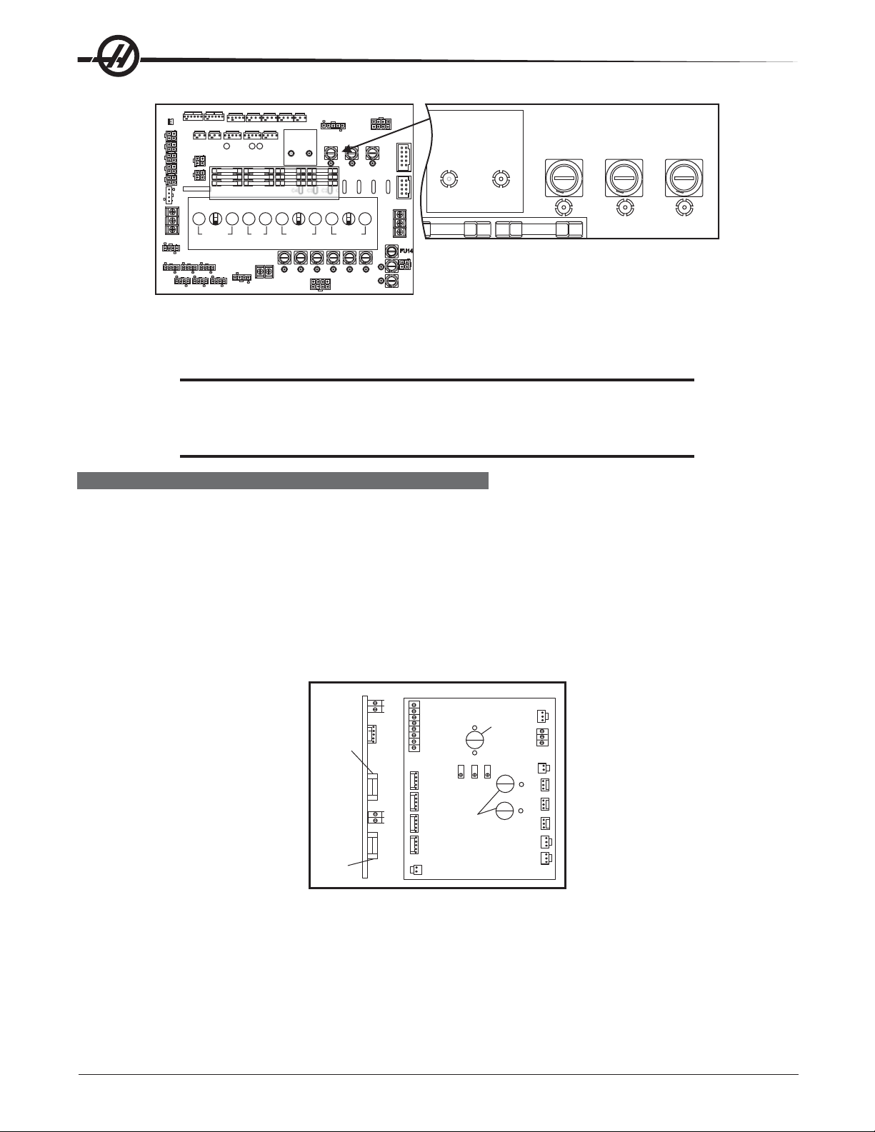
Probe (Option)
Low Voltage Power Supply
T5 Transformer
MOCON-2
(if equipped)
LCD Video/Floppy
3-Phase Breaker
MOCON-1
Processor
K1 Contactor
Power PCB
Power Amplifiers
X, Y, Z, A, B & PC
Optional Servo
Tool Changer Amp
SERVODRIVE
ASSEMBLY
Haas Vector Drive
Wye-Delta Contactors
(underneath)
I/O Board
Single Axis Brake PCB
(if so equipped)
LOWVOLT -------------- 260-244V 243-227V 226-211V 210-195V
Transformer
Terminal block
Control Cabinet General Overview
ELECTRICAL CONNECTIONS
L2
L1
L3
High Volt Low Volt
Ground Line
75 76
488-458V 457-429V 428-403V 402-377V 376-354V
HIGH VOLT
74
LOW VOLT
----------------
260-244V 243-227V 226-211V 210-195V
74
75 76
T5 Transformer
Main Circuit Breaker
1. Hook up the three power lines to the terminals on top of the main switch at upper right of electrical panel
and the separate ground line to the ground bus to the left of the terminals.
NOTE: Make sure that the service wires actually go into the terminal-block clamps. (It
is easy to miss the clamp and tighten the screw. The connection looks fine but
the machine runs intermittently or has other problems, such as servo over-
loads.) To check, simply pull on the wires after the screws are tightened.
96-0284 rev A June 2006
Electrical Service
5
Page 7
2. After the line voltage is connected to the machine, make sure that main circuit breaker (at top-right of rear
cabinet) is off (rotate the shaft that connects to the breaker counterclockwise until it snaps off). Turn on the
power at the source. Using an accurate digital voltmeter and appropriate safety procedures, measure the
voltage between all three pair phases at the main circuit breaker and write down the readings. The voltage
must be between 195 and 260V (360 and 480V for high voltage option).
NOTE: Wide voltage fluctuations are common in many industrial areas; you need to
CAUTION! Make sure the main breaker is set to off and the power is off at your supply
know the minimum and maximum voltage which will be supplied to the
machine while it is in operation. U.S. National Electrical Code specifies that
machines should operate with a variation of +5% to -5% around an average
supply voltage. If problems with the line voltage occur, or low line voltage is
suspected, an external transformer may be required. If you suspect voltage
problems, the voltage should be checked every hour or two during a typical day
to make sure that it does not fluctuate more than +5% or -5% from an average.
panel before you change the transformer connections. Make sure that all
three black wires are moved to the correct terminal block and are tight.
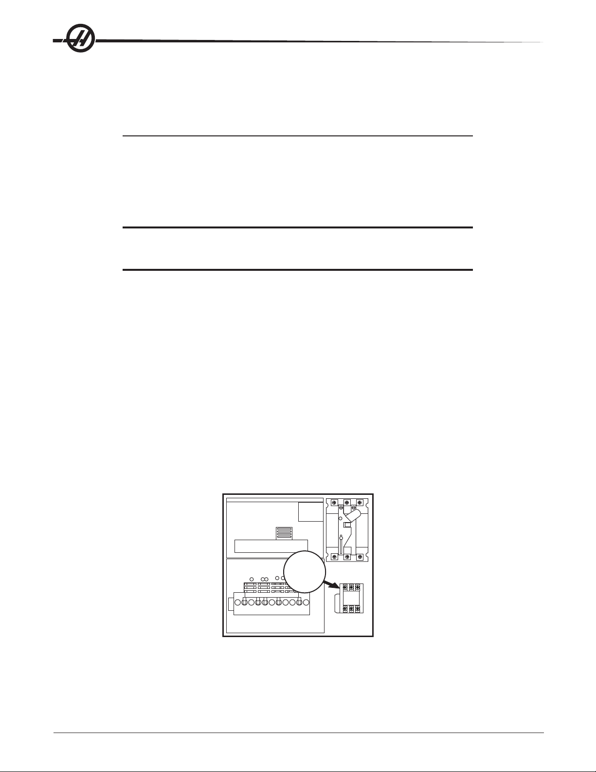
3. Check the connections on the transformer at the bottom-right corner of the rear cabinet. The three black
wires labeled 74, 75, and 76 must be moved to the terminal block triple which corresponds to the average
voltage measured in step 2 above. There are four positions for the input power for the 260V transformer and
five positions for the 480V transformer. The labels showing the input voltage range for each terminal position
are as shown in the previous illustration.
4. Transformer T5 supplies 24V AC used to power the main contactor. There are two versions of this transformer for use on 240 and 400V machines (32-0964B and 32-0965B, respectively). The 240V transformer
has two input connectors located about two inches from the transformer, which allow it to be connected to
either 240V or 200V. Users that have 220V-240V RMS input power should use the connector labeled 200V.
Users with the External High Voltage Option should use the 240V connector if they have 420V-510V 60Hz
power or the 200V connector if they have 50Hz power. Failure to use the correct input connector will result
in either overheating of the main contactor or failure to reliably engage the main contactor .
5. Set the main switch to ON (rotate the shaft that engages the handle on the panel door clockwise until it
snaps into the on position). Check for evidence of problems, such as the smell of overheating components
or smoke. If such problems are indicated, set the main switch to OFF immediately and call the factory
before proceeding.
T5 Transformer
K1
Contactor
WARNING!
Through the Spindle Coolant (TSC) pump is a three phase pump and
must be phased correctly! Improper phasing will cause damage to the
TSC pump and void the warranty. Refer to the TSC start up section if
your machine is equipped with TSC.
6
Electrical Service
96-0284 rev A June 2006
Page 8
6. After the power is on, measure the voltage across the upper terminals on the contactor K1 (located below
the main circuit breaker). It should be the same as the measurements where the input power connects to
the main breaker. If there are any problems, check the wiring.
7. Apply power to the control by pressing the Power On switch on the front panel. Check the high voltage
buss on the Vector Drive (pin 2 with respect to pin 3 on the terminal bus at the bottom of the drive). It must
be between 310 and 360V. If the voltage is outside these limits, turn off the power and recheck steps 2 and
3. If the voltage is still outside these limits, call the factory. Next, check the DC voltage displayed in the
second page of the Diagnostic data on the CRT. It is labeled DC BUS. Verify that the displayed voltage
matches the voltage measured at pins 2 and 3 of the Vector Drive +/- 7V DC.
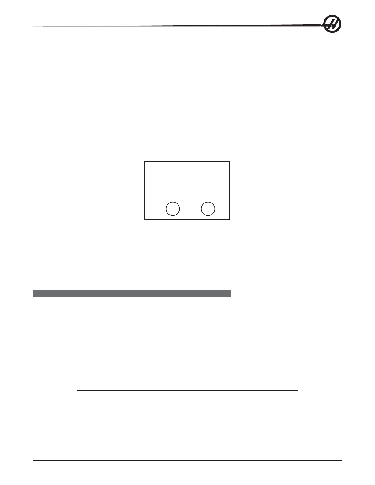
8. Electrical power must be phased properly to avoid damage to your equipment. The Power Supply Assembly PC board incorporates a "Phase Detect" circuit with neon indicators, shown below (disregard for single
phase machines). When the orange neon is lit (NE5), the phasing is incorrect. If the green neon is lit
(NE6), the phasing is correct. If both neon indicators are lit, you have a loose wire. Adjust phasing by
swapping L1 and L2 of the incoming power lines at the main circuit breaker.
PHASE
DETECT
PASS FAIL
6
E
N
5
E
N
WARNING!
All power must be turned off at the source prior to adjusting phasing.
9. Turn off the power (rotate the shaft that engages the handle on the panel door counterclockwise until it
snaps into the off position). Also, set the main switch handle on the panel door to OFF. (Both the handle
and the switch must be set to OFF before the door can be closed). Close the door, lock the latches, and
turn the power back on.
10. Remove the key from the control cabinet and give it to the shop manager.
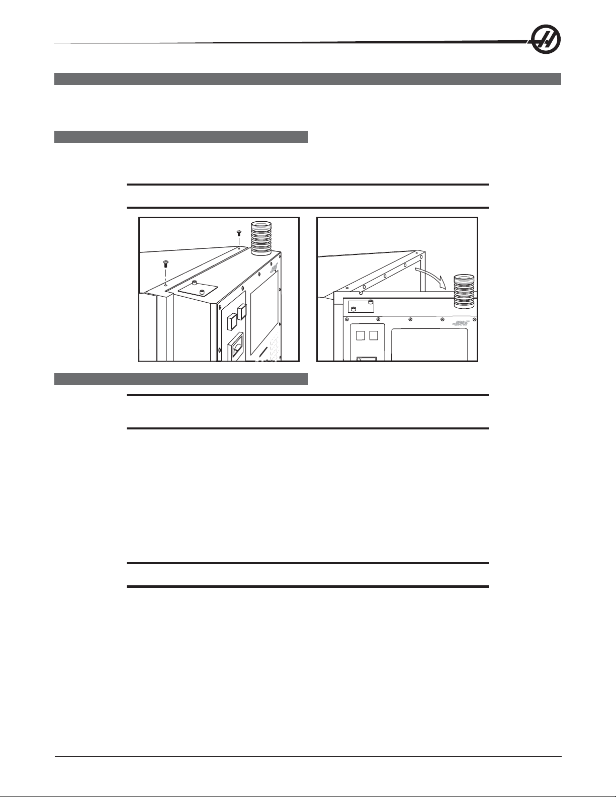
INSTALLATION PROCEDURE FOR EXTERNAL 480V TRANSFORMER
The external transformer adds to overall machine reliability and performance, however it does require extra
wiring and a place to locate it. The external transformer has a 45 KVA rating and provides electrostatically
shielded isolation. This type of transformer acts to isolate all common mode line transients and improve EMI
conducted emissions.
Installation
The transformer should be located as close to the machine as possible. The input and output wiring of the
transformer should conform to the local electrical codes and should be performed by a licensed electrician. The
following is for guidance only , and should not be construed to alter the requirements of local regulations.
The input wire should not be smaller than the 6 AWG for the 45KVA transformer. Cable runs longer than 100"
will require at least one size larger wire. The output wire size should be 4 AWG.
NOTE: Ensure the ground wire has been correctly installed.
The transformer is 480V to 240V isolation transformers with delta wound primary and secondary windings. The
primary windings offer 7 tap positions, 2 above and 4 below the nominal input voltage of 480V.
96-0284 rev A June 2006
Electrical Service
7
Page 9

For domestic installations and all others using 60Hz power, the primary side should be wired as follows:
Input Voltage Range Tap
493-510 1 (504)
481-492 2 (492)
469-480 3 (480)
457-468 4 (468)
445-456 5 (456)
433-444 6 (444)
420-432 7 (432)
This should produce a voltage on the secondary side of 234-243V RMS L-L. Verify this and readjust the taps as
required. At the machine, connect the cables at the input of the internal 230V transformer to the 227-243V
taps. Apply power to the machine and verify that the DC voltage between pins 2 and 3 of the Vector Drive (2nd
and 3rd pins from the left) is 329-345V DC. If not, return to the 480V isolation transformer and readjust the taps
as required. Do not use the taps on the internal 230V transformer to adjust the voltage.
50Hz Installations
The external transformers are 60Hz rated, and cannot be used at 50Hz without derating the input voltage. For
these applications, the internal 230V transformer should be tapped on the lowest setting (195-210V RMS). The
external transformer should be tapped according to the table shown below . If these tap setting do not produce a
DC bus voltage between pins 2 and 3 on the Vector Drive between 320 and 345VDC, readjust the taps on the
external transformer as required. Do not move the taps on the internal transformer from the lowest position.
Input Voltage Range Tap
423-440 1 (504)
412-422 2 (492)
401-411 3 (480)
391-400 4 (468)
381-390 5 (456)
371-380 6 (444)
355-370 7 (432)
8
Electrical Service
96-0284 rev A June 2006
Page 10
FUSE REPLACEMENT
Please read this section in its entirety before attempting to replace any fuses.
Some of the brushless amplifiers have one 15 amp fuse, F1. If this fuse is ever blown, the associated motor will
stop. A light on the amplifier will tell of a blown fuse. If necessary replace the fuse (Haas P/N 93-1089). If the
fuse blows again, the amplifier may be damaged, in which case the amplifier needs to be replaced.
The Power PCB contains three ½-amp fuses located at the top right (FU1, FU2, FU3). If the machine is subject
to a severe overvoltage or a lightning strike, these fuses will blow and turn off all of the power. Replace these
fuses only with the same type and ratings. FU 4, 5, and 5A protect the chip conveyor (FU6 is only used with 3
phase motors).
Size Fuse Name Type Rating (amps) Voltage Location
5mm FU1-FU3 Slo-Blo ½ 250V PSUP pcb, upper right
1/4 F1 Ultra fast 15 250V Amplifier (X, Y, Z, A, B)
5mm FU4, 5 Fast blow 5A 250V PSUP, bottom right corner
OVERVOLTAGE FUSES
WARNING!
The electrical panel will have residual voltage, even after power has
been shut off and/or disconnected . Never work inside this cabinet
until the small green Power On light on the servo amplifiers (servo
drive assembly on brush machines) goes out. The servo amplifiers/
servo drive assembly is on the left side of the main control cabinet
and about halfway down. This light(s) is at the top of the circuit card at
the center of the assembly. Until this light goes out, there are dangerous voltages in the assembly even when power is shut off.
1. Turn machine power off.
2. Turn the main switch (upper right of electrical cabinet) to the off position.
MAINPOWER
ON
OFF
3. Open the cabinet door and wait until the red charge light on the servo drive assembly goes out before
beginning any work inside the electrical cabinet.
4. The three overvoltage fuses are located in a row at the upper right of the Power Supply board. An orange
light will be on to indicate the blown fuse(s).
96-0284 rev A June 2006
Electrical Service
9
Page 11
10A230V
P24
PHASE
DETECT
TB3
FU13
FU12
PASS FAIL
NE6
NE5
NE2
NE3
FU8
NE13
NE7
NE12
FU1
NE1
FU2 FU3
NE2
NE3
P1
P5
P7
32-4076GRev.A
P15
P14
10A115V
MAIN
P30P33P34P35
SPAREFUSES
10A115V
RTY/
USER POWER
P28
PASS FAIL
NE6 NE5
FU7
NE4
TB2
P25
PHASE
DETECT
FU1 FU2 FU3
NE1
C4 C3 C2 C7 C6 C5 C1
10A230V
COOLANT
TSC COOLANT
FU12 FU11 FU10 FU9
NE11 NE10 NE9 NE8
Power Supply Board; Fuse Locations
5. Using a flat tip screwdriver, turn the fuse(s) counterclockwise to remove and replace the blown fuse(s) with
ones having the same type and rating (½ amp, type AGC, 250V).
CAUTION! When the left fuse is blown, it is still possible to operate the machine,
thereby making an overvoltage situation possible. Verify absolute voltage
to the machine does not exceed 200V (max 260 leg to leg or leg to ground,
or 400V on high voltage machines - max 520V leg to leg or leg to ground).
SERVO DRIVER FUSES (VERT - BRUSH MACHINES ONLY)
1. Turn the main switch (upper right of electrical cabinet) to the off position.
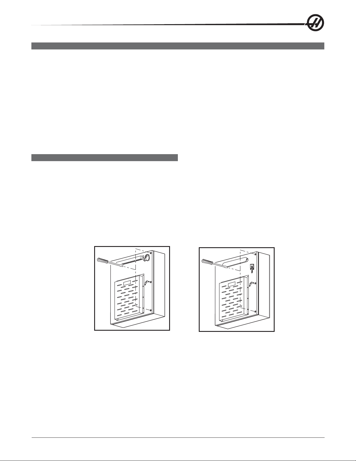
2. Using a large flat tip screwdriver , loosen the three screws on the cabinet door and open the door enough to
safely work on the electrical panel. Wait until at the red charge light on the servo drive assembly goes out
before beginning any work inside the electrical cabinet.
3. On the Servo Drive Assembly, are three individual fuses on each of the Servo Drive boards as shown below.
4. On each of the Servo Driver boards, the fuses (F1, F2, F3) may be replaced by simply pulling them out by
hand and replacing with fuses of the same type and rating (F1, F2: 20 amp, type ABC, 250V; F3: 10 amp,
type ABC, 250V).
P8
F3
P8
LE1
R2 R15 R11
FUSE
FUSE
FU2
FU1
TB1
P11
P9
P12
P13
P10
P5
F1
FUSE
F2
FUSE
P3
F1
F2
P2
TB2 FU3
P1
P2
P3
F1 & F2
P4
P7
10
Servo Drive Assembly; Fuse Locations
Electrical Service
96-0284 rev A June 2006
Page 12
FRONT PANEL
Please read this section in its entirety before attempting to replace any control panel
component.
SL-10 PENDANT COMPONENTS ACCESS
The SL-10 pendant door hinges on the left side. There are two (2) screws on top of the pendant that need
removing so that the pendant door may pivot open.
CAUTION! Do not pinch the cable when the door is closed.
LCD ASSEMBLY REPLACEMENT
CAUTION! Use an electrostatic discharge (ESD) strap on wrist when working inside
the pendant.
1. Turn the power off and disconnect power to the machine.
2. Remove the screws holding the cover panel on the back of the control panel. Take care to hold the cover
panel in place until all screws have been removed.
3. Disconnect the data cable from the receiver board on the LCD assembly (J3). Disconnect the power cable
and ground wire from the power supply board on the LCD assembly (TB1). Disconnect the cables to the
keyboard from the receiver assembly (P1) and power supply (TB2) on the LCD assembly.
4. Remove the four (4) hex nuts and washers beginning with the bottom, then remove the LCD assembly and
set aside in a safe place.
CAUTION! Do not drop or damage the LCD when removing it from the control panel.
5. Use gloves to avoid getting fingerprints on the new LCD. Replace by sliding the new assembly onto the four
bolts (two each on top and bottom): eight bolts (four each on top and bottom) for Vertical machines. Place
the washers and hex nuts on the bolts to hold in place. Once all washers have been attached and nuts
have been hand-tightened, tighten down completely .
96-0284 rev A June 2006
Electrical Service
11
Page 13
Receiver Assembly
Keyboard Cables
Power Supply Board
Data Cable
Back of Operator’ s Pendant
Power Supply
Cable
6. Plug the keyboard cables into the new receiver board (P1) and the power supply (TB2). Plug the power
cable into the power supply board (TB1) and attach the green wire to ground. Plug the data cable into the
receiver board (J3).
7. Replace the back cover panel and attach with the four screws previously removed.
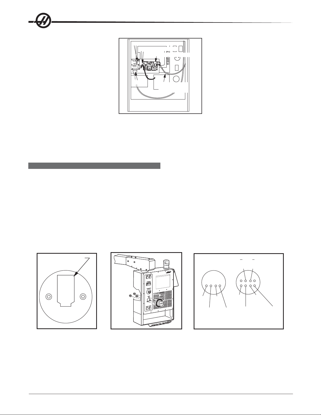
JOG HANDLE
The Jog handle is actually a 100-line-per-revolution encoder, used to move one axis at a time. If no axis is
selected for jogging, turning of the crank has no effect. When the axis being moved reaches its travel limits, the
handle inputs will be ignored in the direction that would exceed the travel limits. Parameter 57 can be used to
reverse the direction of operation of the handle.
Jog Handle Replacement
1. Turn the machine power off.
2. Remove the screws holding the cover panel on the back of the control panel. Take care to hold the cover
panel in place until all screws have been removed.
3. Unplug the cable leading to the jog handle encoder. Important! The blank pin side of the connector must
face as shown below when reconnecting; otherwise, damage may occur to the machine.
Blank pin goes to this
side of connector
+5V
BLK
Jog Handle Encoder Jog Handle Removal Jog Handle Wiring Diagram
A
RED
GND
WHT
+5V
RED
B
GRN
A
YEL
GND
WHT/
RED
B
BRN
WHT/
YEL
A
B
WHT/
BRN
4. Using the 5/64" allen wrench, loosen the two screws holding the knob to the control panel and remove.
5. Remove the three screws holding the jog handle encoder to the control panel and remove.
6. Replacement is reverse of removal. Keep in mind the important notice in Step 3.
12
Electrical Service
96-0284 rev A June 2006
Page 14

POWER ON/OFF SWITCHES
The Power On switch engages the main contactor. The On switch applies power to the contactor coil and the
contactor thereafter maintains power to its coil. The Power Off switch interrupts power to the contactor coil and
turns power off. Power On is a normally open switch and Power Off is normally closed. The maximum voltage
on the Power On and Power Off switches is 24V AC and is present any time the main circuit breaker is on.
EMERGENCY STOP SWITCH
The Emergency Stop switch is normally closed. If the switch opens or is broken, servo power is removed
instantly. This will also shut off the turret, spindle drive, and coolant pump. The Emergency Stop switch will
shut down motion even if the switch opens for as little 0.005 seconds. Note that Parameter 57 contains a
status switch that if set, will cause the control to be powered down when Emergency Stop is pressed.
You should not normally stop a tool change with Emergency Stop as this will leave the tool changer in an
abnormal position that takes special action to correct
If the lathe turret or mill tool changer (T/C) should become jammed, the control will automatically come to an
alarm state. To correct this, push the Emergency Stop button and remove the cause of the jam. Push the
Reset key to clear any alarms. Push Zero Return and the Auto All Axes to reset the Z-axis and turret or T/C.
Never put your hands near the turret or T/C when powered unless E-Stop is pressed.
KEYBOARD BEEPER
There is a beeper under the control panel that is used as an audible response to pressing keyboard buttons
and as a warning beeper. The beeper is a one kHz signal that sounds for about 0.1 seconds when any keypad
key, Cycle Start, or Feed Hold is pressed. The beeper also sounds for longer periods when an auto-shutdown is
about to occur and when the “Beep at M30” setting is selected.
If the beeper is not audible when buttons are pressed, the problem could be in the keypad, keyboard interface
PCB or in the speaker. Check that the problem occurs with more than one button and check that the beeper
volume is not turned down or that it wasn’t disconnected. If lamps don’t turn on, check the GFCI.
LAMP ON/OFF SWITCH
An on/off switch is supplied for the operator's lamp. It is located on the side of the operator’s pendant. The
operator's lamp uses 115V AC taken from P19 on the main power distribution.
SWITCH REPLACEMENT
1. Turn the machine power off. Remove the screws holding the cover panel on the back of the control panel.
T ake care to hold the cover panel in place until all screws have been removed.
2. Disconnect all leads to the switch connectors. Ensure all leads are properly marked for reconnecting later.
3. Unscrew the two small set screws, one on top and one on the bottom, and turn the switchcounterclock-
wise to loosen. Separate from the front portion and pull out.
4. For replacement, screw the front and rear portions together (reverse of removal) and tighten down the two
small set screws when the switch is properly positioned.
NOTE: The Power On, Power Off, and Emergency Stop switches must all have the
connectors on the bottom of the switch.
5. Reconnect all leads to the correct switch.
96-0284 rev A June 2006
Electrical Service
13
Page 15
SPINDLE LOAD METER
The load meter measures the load on the spindle motor as a percentage of the rated continuous power of the
motor. There is a slight delay between a load and the actual reflection of the meter. The eighth A-to-D input also
provides a measure of the spindle load for cutter wear detection. The second page of diagnostic data will
display % of spindle load. The meter should agree with this display within 5%. The spindle drive display #7
should also agree with the load meter within 5%. Note that there are different types of spindle drive that are
used in the control. They are all equivalent in performance but are adjusted differently.
Spindle Load Meter Replacement
1. Turn the power off and disconnect power to the machine. Remove the screws holding the cover panel on
the back of the control panel. Take care to hold the cover panel in place until all screws are removed.
2. Disconnect the two leads at the back of the spindle load meter assembly. Ensure the two leads are
properly marked for reconnecting later.
3. Unscrew the four screws that hold the spindle load meter assembly to the control panel. Take care to hold
the assembly in place until all screws have been removed. Remove the assembly.
4. Installation is reverse of removal. Ensure leads go to the correct location.
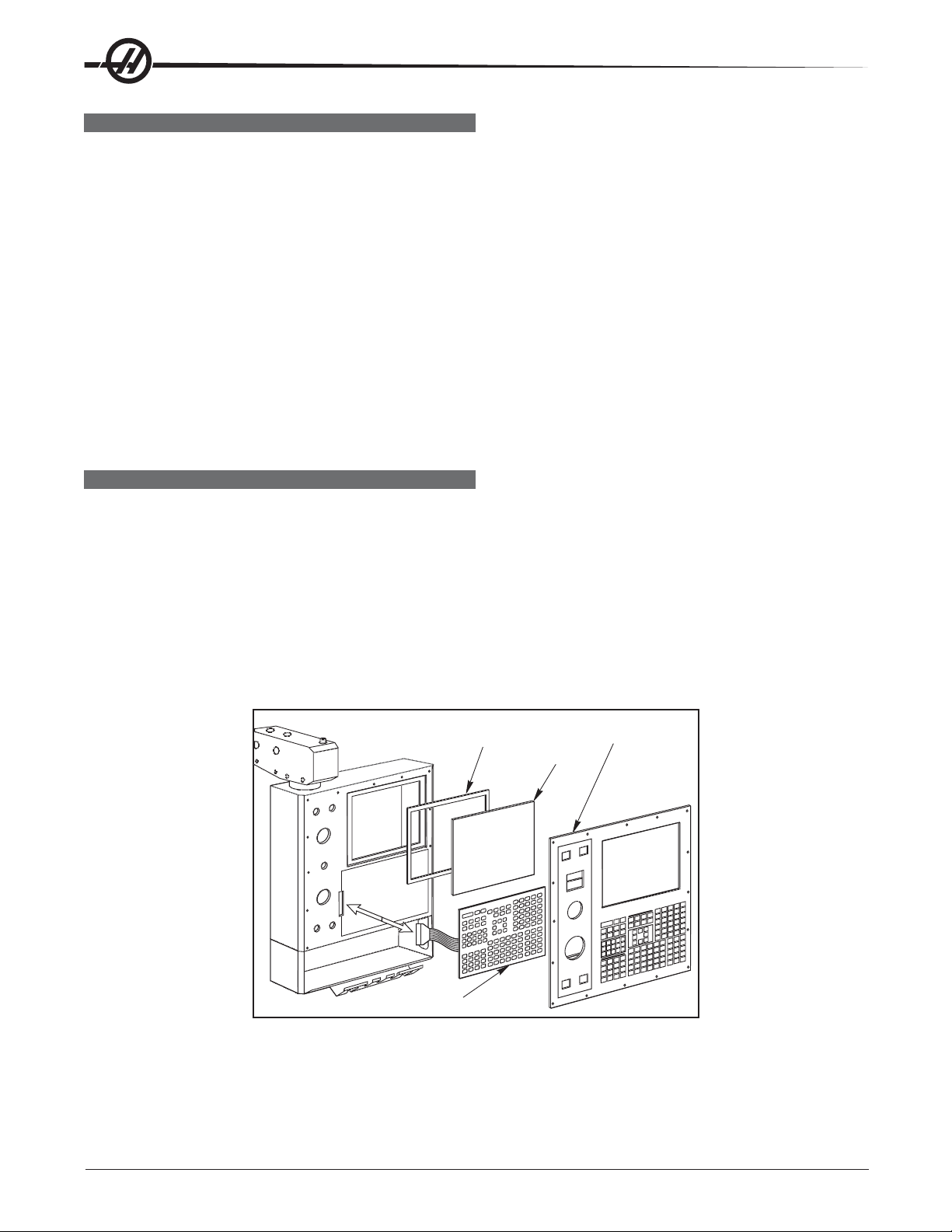
KEYPAD REPLACEMENT
1. Turn the power off and disconnect power to the machine. Remove the screws holding the rear cover panel
to the back of the control panel. Take care to hold the cover panel in place until all screws are removed.
2. Unplug the keypad's 24-pin ribbon cable from the Keyboard Interface board.
3. Remove the screws from the front of the control panel. Take care to hold the front cover panel in place until
all screws have been removed. Remove the pieces and set aside in a safe place.
4. Using a flat, blunt tool, such as putty knife, pry the keypad away from the control panel. Pull the ribbon
cable through the opening in the control to remove.
5. To replace, first put the bezel spacer in place and fasten temporarily with screws in the top corners.
Gasket
Glass
Keypad
Keypad Installation
Front Bezel
6. Insert the ribbon cable through the opening in the control panel. Expose the adhesive strip on the back of
the keypad and press it into place in the upper right corner of the keypad recess. Press to the control
panel to mount. Plug the ribbon cable into the Keyboard Interface board, taking care to not bend the pins.
14
Electrical Service
96-0284 rev A June 2006
Page 16

7. Replace the front and rear cover panels and fasten with the screws that were previously removed.
SERIAL KEYBOARD INTERFACE REPLACEMENT
NOTE: Refer to "Cable Locations" for a diagram of this board.
1. Follow all precautions noted previously before working in the control cabinet.
2. Turn the main switch (upper right of electrical cabinet) to the off position.
3. Remove the four screws on the back of the control box, then remove the cover panel. Take care to hold the
panel in place until all screws have been removed.
4. Disconnect all leads to the Serial Keyboard Interface (SKBIF) board. Ensure all cables are properly la-
beled.
5. After all cables have been disconnected, unscrew the four screws holding the Serial KBIF board to the
control box. Take care to hold the board in place until all screws have been removed. Place the screws and
standoffs aside for later use.
6. Replace the Serial KBIF board, using the four screws previously removed, starting at the top right. Attach
the screw and standoff loosely , then all other screws and st andoffs, until all are mounted. T ighten down.
7. Reconnect all cables to the Serial KBIF board at their proper locations.
8. Verify whether the machine is equipped with either a speaker or a beeper. Align the toggle switches of
Switch 1 on the Serial KBIF board to their appropriate positions. Beeper operation requires that both S1
switches be set to ‘B’; speaker operation requires that both S1 switches be set to ‘S’.
96-0284 rev A June 2006
Electrical Service
15
Page 17

SOLENOIDS
Please read this section in its entirety before attempting to replace any solenoid assemblies.
TOOL RELEASE PISTON (TRP) AIR SOLENOID ASSEMBLY (HORIZ & VERT)
Removal
1. Turn machine power on and raise spindle head to uppermost position. Turn power off.
2. Remove sheet metal at rear and/or top of machine to access the back of the spindle (Mechanical Service).
3. Remove air supply from machine.
4. Disconnect all air lines from the air solenoid assembly. Do not remove fittings, remove lines from fittings.
5. Vert: Disconnect the two leads from the low air pressure sensor.
6. Unscrew the air solenoid assembly from the tool release piston assembly, taking care to not disturb the
position of the clamp/unclamp switches. It may be necessary to remove the tool release piston to access
the solenoid assembly .
7. Vert: Unplug the wiring leading to the plug marked on the solenoid bracket as “880 from I/O PCB to
Solenoid Valves” and the plug marked “Spare”.
8. Unscrew the air solenoid from the air solenoid assembly.
9. Vert: Remove the SHCS holding the assembly to the bracket and remove the assembly.
Installation
1. Install the new air solenoid. Take care to not disturb the position of the clamp/unclamp switches.
2. Vert: Replace air solenoid assembly and attach to bracket with the SHCS previously removed. Tighten
securely.
3. Reinstall the tool release piston assembly (Mechanical Service).
4. Vert: Reconnect the two leads to the low air preassure sensor.
5. Reconnect the wiring to the plugs on the solenoid bracket.
6. Ensure all air lines are reconnected to their proper fittings.
7. Reconnect air supply to the machine, and check for leaks.
8. Replace the sheet metal.
16
Electrical Service
96-0284 rev A June 2006
Page 18
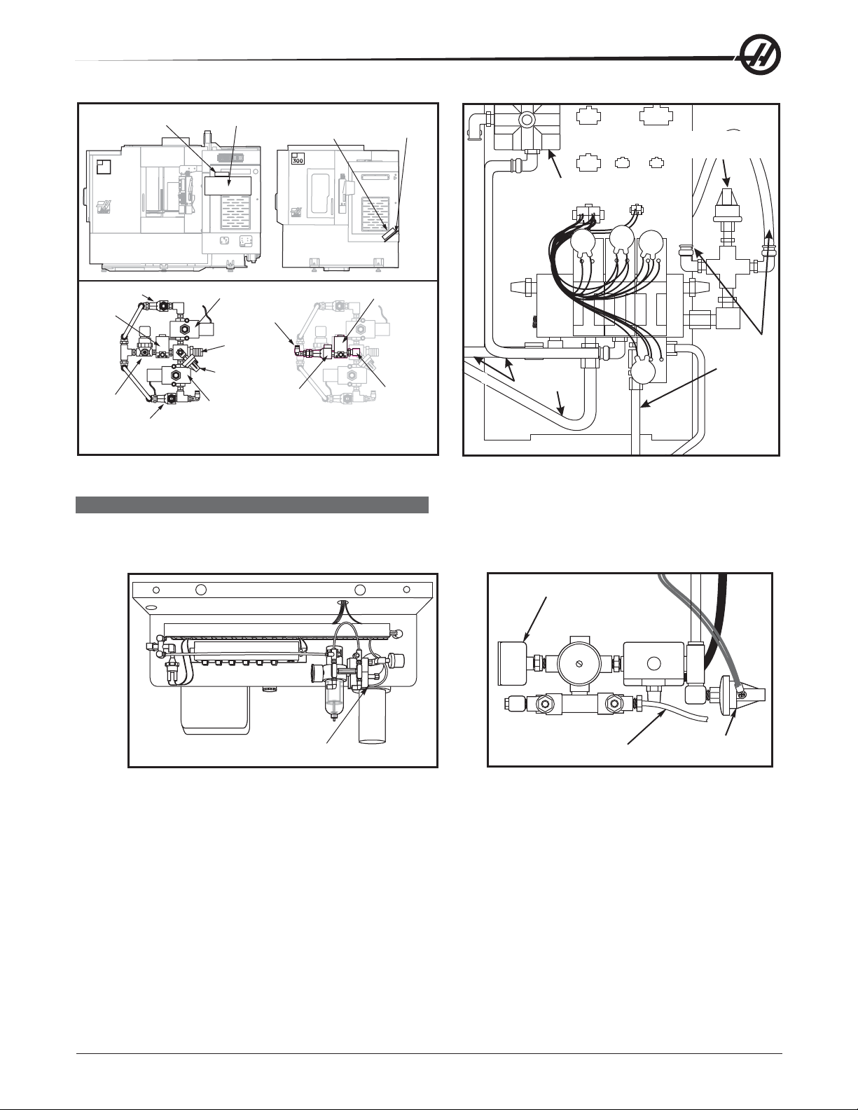
Air Solenoid
Disconnect
all air lines
Disconnect
all air lines
Air solenoid
assembly
Low air pressure
sensor
Assembly
EC
400
Motor Shroud
Air Solenoid
Assembly
EC
Sheet Metal
Tray
Check Valve Switch
Pre-
Charge
TRP Solenoid
To TSC
TSC Solenoid
Inlet
Pressure
Switch
Regulator
Check Valve Switch
TRP
Solenoid
Basic Air SolenoidAssembly
Check
Valve
Switch
Air Solenoid Assembly
With TSC Feature Added
Junction
Elbow
Locations of EC-300 and EC-400 TRP Solenoids VF-Series Air Solenoid Assembly
SPINDLE LUBE AIR SOLENOID
Removal
1. Turn the machine power off and remove the air supply from the machine.
Pressure Gauge
2. a. Lathe: Disconnect the lube line from the spindle lube air solenoid assembly.
b. Mill: Disconnect the air lines from the spindle lube air solenoid assembly.
3. Disconnect the electrical leads from the main air line pressure switch.
4. Lathe: Unscrew the solenoid assembly pressure gauge from the assembly .
5. Unscrew the entire solenoid assembly from the T-fitting.
96-0284 rev A June 2006
Spindle
Lube
Solenoid
Lube/Air Panel (Rear View) Spindle Lube/Air Solenoid Assembly (Top View)
Lube Line
Main Air Line
Pressure Switch
Electrical Service
17
Page 19

Installation
1. Reattach the solenoid assembly at the T-fitting.
2. a. Lathe: Replace the pressure gauge on the solenoid assembly and reconnect the lube line.
b. Mill: Reconnect all air lines.
3. Reconnect the electrical leads to the main air line pressure switch.
4. Restore the air supply to the machine.
PNEUMATIC CHUCK/TURRET CLAMP/UNCLAMP SOLENOID (LATHE)
Removal
1. Turn machine power off and remove the air supply from the machine.
2. Pneumatic Chuck: Disconnect the two air hoses from the pneumatic chuck clamp/unclamp solenoid.
Turret: Disconnect the three air hoses from the turret clamp/unclamp solenoid (see the Turret In/Out
Adjustment), and disconnect exhaust lines.
3. Unplug the solenoid electrical lead (located on the rear of the lube air panel).
4. Remove the two SHCS holding the assembly to the bracket and remove the assembly.
Installation
1. Replace the air solenoid assembly and attach it to the bracket with the two SHCS. Tighten securely.
2. Reconnect the electrical connection to the solenoid at the switch bracket.
3 Reconnect the two (three for Turret) air lines and turret exhaust lines, ensuring that all connections are
tight and do not leak.
4. Restore the air supply to the machine.
18
Electrical Service
96-0284 rev A June 2006
Page 20

PCB REPLACEMENT
Please read this section in its entirety before attempting to replace any PCBs
MICROPROCESSOR ASSEMBLY
The microprocessor assembly is in the control cabinet at the top left position. It contains three large boards.
They are: Microprocessor, the Video/Keyboard and the MOCON. All three boards of the processor assembly
receive power from the low voltage power supply. The three PCBs are interconnected by a local buss on dual
50-pin connectors. At power-on, some diagnostic tests are performed on the processor assembly and any
problems found will generate Alarms 157 or 158. In addition, while the control is operating, it continually tests
itself and a self test failure will generate Alarm 152.
MOCON, VIDEO/KEYBOARD, & MICROPROCESSOR
WARNING!WARNING!
WARNING!
WARNING!WARNING!
The electrical panel will have residual voltage, even after power has
been shut off and/or disconnected . Never work inside this cabinet
until the small red Charge light on the servo amplifiers go out. The
servo amplifiers are on the left side of the main control cabinet and
about halfway down. This light is at the top of the circuit card at the
center of the assembly. Until this light goes out, there are dangerous
voltages in the assembly even when power is shut off.
Ground straps must be used when handling boards.
NOTE: Board arrangement may differ from the order of replacement that follows.
Steps for replacement will only differ in which board may need to be removed
before getting to the necessary board.
MOTOR CONTROLLER (MOCON)
Machines are equipped with a microprocessor-based brushless motor controller board (MOCON) that replaces
the motor interface in the brush type controls. It runs in parallel with the main processor , receiving servo
commands and closing the servo loop around the servo motors.
In addition to controlling the servos and detecting servo faults, the motor controller board (MOCON) is also in
charge of processing discrete inputs, driving the I/O board relays, commanding the spindle, and processing the
jog handle input. It also controls 6 axes, so there is no need for an additional board for a 5-axis machine.
MOCON Board Replacement
NOTE: Refer to "Cable Locations" for a diagram of this board.
1. Turn machine power off.
2. Turn the main switch (upper right of electrical cabinet) to the off position.
3. Open the cabinet door enough to safely work on the electrical panel. Wait until the red charge light on the
servo amplifiers (servo drive assembly on brush machines) goes out before beginning any work.
4. Disconnect all leads to the Motor Controller (MOCON) board, and ensure all cables are properly labeled.
5. After all cables have been disconnected, unscrew the standoffs, taking care to hold the board in place until
all standoffs have been removed.
NOTE: If the Video/Keyboard or Processor boards need replacing, skip the next step.
6. Replace the MOCON board, attaching it to the Video/Keyboard (beneath the MOCON board) with the
standoffs, and reconnect all leads (previously removed) to their proper connections.
7. If a second MOCON board is present, be sure to connect the jumper on the second MOCON board.
96-0284 rev A June 2006
Electrical Service
19
Page 21

VIDEO/KEYBOARD
The Video/Keyboard PCB generates the video data signals for the monitor and the scanning signals for the
keyboard. In addition, the keyboard beeper is generated on this board. There is a single jumper on this board
used to select inverse video. The video PCB connectors are:
P1 Power connector J11 SPARE
J3 Keyboard (700) J12 Floppy
J4 Address bus J13 Video (760)
J5 Data J14 RS422 B
J10 Floppy V+ J15 RS422 A
Video/Keyboard Replacement
NOTE: Refer to "Cable Locations" for a diagram of this board.
1. Remove the MOCON board as previously described.
2. Disconnect all leads to the Video/Keyboard. Ensure all cables are properly labeled for reconnecting later.
3. After all cables have been disconnected, unscrew the standoffs, taking care to hold the board in place until
all standoffs have been removed.
NOTE: If the Processor board needs replacing, please skip the next step.
4. Replace the Video/Keyboard, attaching it to the Processor board with the standoffs.
5. Reconnect all leads (previously removed) to their proper connections.
6. Replace the MOCON board.
MICROPROCESSOR PCB (68ECO30)
The Microprocessor PCB contains the 68ECO30 processor running at 40 MHz, one 128K EPROM; between
1MB and 16MB of CMOS RAM and betwen 512K and 1.5MB of Fast Static RAM. It also contains a dual serial
port, a battery to backup RAM, buffering to the system buss, and eight system status LED’s.
Two ports on this board are used to set the point at which an NMI is generated during power down and the point
at which Reset is generated during power down.
The eight LED’s are used to diagnose internal processor problems. As the system completes power up testing,
the lights are turned on sequentially to indicate the completion of a step. The lights and meanings are:
R UN Program Running Without Fault Exception. (Normally On) - If this light does not come on, or goes
out after coming on, there is a problem with the microprocessor or the software running in it. Check all
of the buss connectors to the other two PCB’s and ensure all three cards are getting power.
PGM Program Signature Found in Memory. (Normally On) - If this light does not come on, it means that
the main CNC program package was not found in memory, or that the auto-start switch was not set.
Check that Switch S1-1 is on and the EPROM is plugged in.
CRT CRT/LCD Video Initialization Complete. (Normally On) - If the light doesn’t come on, there is a
problem communicating with the Video PCB. Check buss connectors to ensure it is getting power.
MSG Power-on Serial I/O Message Output Complete. (Normally On) - If this light does not come on,
there is a problem with serial I/O or interrupts. Disconnect anything on the external RS-232 and retest.
SIO Serial I/O Initialization Complete. (Normally On) - If this light does not come on, there is a problem
with the serial ports. Disconnect anything on the external RS-232 and test again.
PO R Power-On-Reset Complete. (Normally On) - If this light does not come on, there is a problem with
the Processor PCB. Check that the EPROM is plugged in. Test the card with buss connectors off.
20
Electrical Service
96-0284 rev A June 2006
Page 22

HA LT Processor Halted in Catastrophic Fault. (Normally Dim) - If this light comes on, there is a problem
with the Processor PCB. Check that the EPROM is plugged in. Test the card with buss connectors off.
+5V +5V Logic Power Supply is Present. (Normally On) - If this light does not come on, check the low
voltage power supply and check that all three phases of 230V input power are present.
There is 1 two-position DIP switch on the Processor PCB labled S1. Switch S1-1 must be ON to auto-start the
CNC operational program. If S1-1 is OFF, the PGM light will remain off. Switch S2-1 is used to enable Flash. If
it is disabled it will not be possible to write to Flash.
The processor connectors are:
J1 Address buss J5 Serial port #2 (for auxiliary 5th axis) (850A)
J2 Data buss J3 Power connector
J4 Serial port #1 (for upload/download/DNC) (850) J6 Battery
Memory Retention Battery
The memory retention battery (3.3V Lithium battery) is soldered into the Processor PCB. It maintains the
contents of CMOS RAM during power off periods. A minimum voltage of 2.5V DC is required for proper operation. Prior to this battery being unusable, an alarm is generated indicating low battery. If the battery is replaced
within 30 days, no data is lost. The battery is not needed when the machine is powered on. Connector J6 on
the Processor PCB can be used to connect an external battery.
T o replace the battery, the 4-pin jumper, attached to a fresh battery , has to be temporarily att ached to J-6
before the old battery is removed. With the jumper in place, un-solder the old battery and remove. Install a new
battery and solder in place, then remove the temporary jumper.
NOTE: Do not attach the jumper after the old battery has been removed or remove the
jumper if a fresh battery has not been installed. This will result in complete
machine memory loss, which cannot be reversed.
Processor Board Replacement
NOTE: Refer to "Cable Locations" for a diagram of this board.
1. Remove the MOCON board, and the Video/Keyboard as previously described.
2. Disconnect all leads to the Processor board. Ensure all cables are properly labeled for reconnecting later.
3. After all cables have been disconnected, unscrew the standoffs, taking care to hold the board in place until
all standoffs have been removed.
4. Replace the Processor board, attaching it to the electrical cabinet with the standoffs, reconnect all leads
(previously removed) to their proper connections, and replace Video/Keyboard and MOCON board.
Servo Driver Board Replacement (Vertical Machines)
NOTE: Refer to "Cable Locations" for a diagram of this board.
1. Follow all precautions noted previously before working in the electrical cabinet.
2. Disconnect all leads to the Servo Driver (Driver) board that you wish to replace. Ensure all cables are
properly labeled for reconnecting later.
NOTE: When replacing any Driver board, it will be necessary to disconnect all leads
on all Driver boards in order to remove or replace the board.
3. Remove the board by first removing the two screws that fasten it to the cabinet. Take care to hold the board
in place until both screws have been removed.
4. Replace the Driver board, attaching it to the cabinet with the two screws previously removed.
5. Reconnect all leads to all boards. Ensure the red and black leads go to the appropriate connections.
96-0284 rev A June 2006
Electrical Service
21
Page 23
INPUT/OUTPUT ASSEMBLY
The I/O PCB contains a circuit for electronically turning drawbar motor power on and off to prevent any arcing of
the motor relays and increase their life. This includes an adjustable current limit to the tool changer. Potentiometer R45 adjusts the current limit to the drawbar motors, and R45 limits current to between 9 and 11 amps.
The I/O PCB also contains a circuit for sensing a ground fault condition of the servo power supply. If more than
1.75 amps is detected flowing through the grounding connection of the 160V DC buss, a ground fault alarm is
generated and the control will turn off servos and stop.
Relay K6 is for the coolant pump 230V AC. It is a plug-in type and is double-pole. Relays K9 through K12 are
also plug-in types for controlling the drawbar motors.
The Input/Output Assembly consists of a single printed circuit board called the I/O PCB.
I/O Board Replacement
NOTE: Refer to "Cable Locations" for a diagram of this board.
1. Follow all precautions noted previously before working in the electrical cabinet.
2. Disconnect all leads to the Input/Output board and move aside for removal. Ensure all cables are properly
labeled for reconnecting later.
3. Remove the board by first removing the twelve screws that fasten it to the cabinet. Take care to hold the
board in place until all screws have been removed.
4. Replace the I/O board, attaching it to the cabinet with the twelve screws previously removed, and reconnect
all leads to the I/O board. Check for ant additional jumper settings per I/O release notes.
POWER TRANSFORMER ASSEMBLY (T1)
The power transformer assembly converts three-phase input power (50/60Hz) to three-phase 230V and 115V
power. T wo transformers are used, depending on the input voltage range. The low voltage transformer has four
input connections to allow for a range of voltages from 195V RMS to 260V RMS. The high voltage transformer
has five input connections and will accept a range of voltages from 354V RMS to 488V RMS.
The 230V is used to power the spindle drive, which also develops the 325V DC power for the axis servo amplifiers. The 115V is used by the video monitor, solenoids, fans and pumps, in addition to supplying power to the
main LVPS used by the control electronics.
The transformer assembly is located in the lower right hand corner of the main cabinet. Besides the high/low
voltage variations, two different power levels are available depending on the spindle motor used. The small and
large transformers have power ratings of 14 KVA and 28 KVA, respectively, and are protected by the main
circuit breaker.
High Volt Low Volt
75
76
488-458V 457-429V 428-403V 402-377V 376-354V
HIGH VOLT
74
LOW VOLT
----------------
260-244V 243-227V 226-211V 210-195V
74
75
76
22
Polyphase Bank Transformer
Electrical Service
96-0284 rev A June 2006
Page 24

Primary Connection To T1
Input power to T1 is supplied through CB1, the main circuit breaker. Three-phase 230 to T1 is connected to the
first three terminals of TB10.
Circuit breaker CB1 is used to protect the spindle drive and to shut off all power to the control. The locking On/
Off handle on the outside of the control cabinet shuts this breaker off when it is unlocked. A trip of this breaker
indicates a serious overload problem and should not be reset without investigating the cause of the trip.
Main Contactor K1
Main contactor K1 is used to turn the control on and off. The Power On switch applies power to the coil of K1
and after it is energized, auxiliary contacts on K1 continue to apply power to the coil. The Power Off switch on
the front panel will always remove power from this contactor .
When the main contactor is off, the only power used by the control is supplied through two ½ amp fuses to the
circuit that activates the contactor . An overvoltage or lightning strike will blow these fuses and shut of f the main
contactor.
The power to operate the main contactor is supplied from a 24V AC control transformer that is primary fused at
½ amp. This ensures that the only circuit powered when the machine is turned off is this transformer and only
low voltage is present at the front panel on/off switches.
Voltage Selection Taps
There are four labeled plastic terminal blocks. Each block has three connections for wires labeled 74, 75, and
76. Follow the instructions printed on the transformer.
Secondary Connection To T1
The secondary output from T1 is 115V AC three-phase CB2 that protects the secondary of transformer T1 and
is rated at 25 amps.
Optional 480V Transformer
60Hz 50Hz
Input Voltage Range Tap Input Voltage Range Tap
493-510 1 (504) 423-440 1 (504)
481-492 2 (492) 412-422 2 (492)
469-480 3 (480) 401-411 3 (480)
457-468 4 (468) 391-400 4 (468)
445-456 5 (456) 381-390 5 (456)
433-444 6 (444) 371-380 6 (444)
420-432 7 (432) 355-370 7 (432)
Power-Up Low Voltage Control Transformer (T5)
The low voltage control transformer, T5, supplies power to the coil of the main contactor K1. It guarantees that
the maximum voltage leaving the Power Supply assembly when power is off is 12V AC to earth ground. It is
connected via P5 to the Power PCB.
Operator's Work Light
Main transformer (T1) outputs 115V AC to the work light.
POWER SUPPLY ASSEMBLY
All power to the control passes through the power supply assembly . It is located on the upper right corner of
the control cabinet.
Power PCB (PSUP)
The low voltage power distribution and high voltage fuses and circuit breakers are mounted on a circuit board
called the Power PCB.
96-0284 rev A June 2006
Electrical Service
23
Page 25

Secondary Circuit Breakers
The following circuit breakers are located on the Power supply assembly:
CB2 Controls the 115V power from the main transformer to the servo transformers and, if tripped, will
turn off the servo motors and air solenoids. CB2 could be blown by a severe servo overload.
CB3 Controls the power to coolant pump only. It can be blown by an overload of the coolant pump
motor or a short in the wiring to the motor.
CB5 Controls power to the TSC coolant pump only. It can be tripped by an overload of the TSC coolant
pump motor or a short in the wiring to the motor.
CB6 Single-phase 115V protected output for the user.
GFCI Single-phase 115V 10A protected ground fault interrupt circuit.
Power PCB (PSUP) Replacement
NOTE: Refer to "Cable Locations" for a diagram of this board.
1. Follow all precautions noted previously before working in the electrical cabinet
2. Disconnect all leads to the Power PCB (PSUP) and move aside for removal. Ensure all cables are properly
labeled for reconnecting later.
3. After all cables have been disconnected, remove the seven screws holding the Power board to the cabinet
and remove the board. Take care to hold the Power board in place until all screws have been removed.
NOTE: If you need to replace the Low Voltage Power Supply board, please skip the
next step.
4. Replace the Power board, attaching it with the seven screws previously removed. Do not forget to use the
lower left screw for a ground connection.
5. Reconnect all cables to the Power board at their proper location. Always refer to release notes for any
additional information.
LOW VOLTAGE POWER SUPPLY
The low voltage power supply provides +5V DC, +12V DC, and -12V DC to all of the logic sections of the
control. It operates from 115V AC nominal input power, and continues to operate correctly over 90 to 133V AC.
For Lathes, a servo power supply is mounted on top of the Low Voltage Power Supply supply. It furnishes +12V
and -12V power to the servo amplifiers. This supply is powered from the 335V DC bus from the sub-spindle
vector drive.
Low Voltage Power Supply (LVPS) Replacement
NOTE: Refer to "Cable Locations" for a diagram of this board.
1. Remove the Power Distribution (Power) board as previously described.
2. Disconnect all leads to the Low Voltage Power Supply (LVPS) board. Ensure all cables are properly
labeled for reconnecting later.
3. After all cables have been disconnected, unscrew the two standoffs at the bottom of the board. Unscrew
the remaining two screws at the top of the LVPS board, taking care to hold the board in place until all
screws have been removed.
4. Replace the LVPS board, attaching it to the cabinet with the two screws and standoffs previously removed.
5. Replace the Power board as previously described.
24
Electrical Service
96-0284 rev A June 2006
Page 26

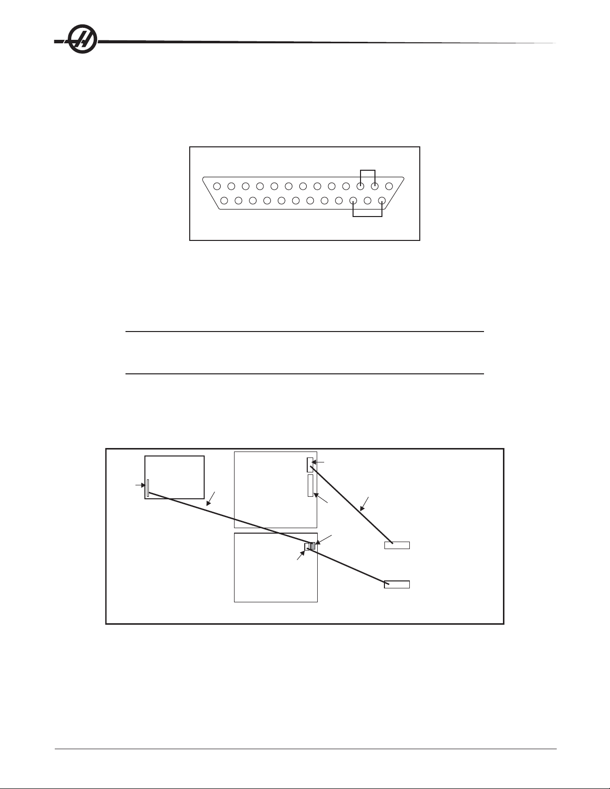
RS-232 SERIAL INTERFACE
There are two connectors used for the RS-232 interface. The RS-232 connector on the back of most PCs is a
male DB-25, so only one type of cable is required for connection to the controller, or between controllers. This
cable must be a DB-25 male on one end and a DB-25 female on the other. Pins 1, 2, 3, 4, 5, 6, 7, 8, and 20
must be wired one-to-one. It cannot be a Null Modem cable, which inverts pins 2 and 3. To check cable type,
use a cable tester to check that communication lines are correct. The controller is DCE (Data Communication
Equipment). This means that it transmits on the RXD line (pin 3) and receives on the TXD line (pin 2). The RS232 connector on most PC's is wired for DTE (Data Terminal Equipment), requiring no special jumpers.
The Down Line DB-25 connector is only used when more than one controller is to be used. The first controller's
down line connector goes to the second controller's up line connector, etc.
The RS-232 interface sends and receives seven dat a bits, even p arity , and two stop bit s. The interface
must be set correctly. The data rate can be between 110 and 19200 bits per second. When using RS-232, it is
important to make sure that Parameter 26 (RS-232 Speed) and 33 (X-on/X-off Enable) are set to the same value
in the controller and PC.
If Parameter 33 is set to on, the controller uses X-on and X-off codes to control reception, so be sure your
computer is able to process these. It also drops CTS (pin 5) at the same time it sends X-off and restores CTS
when is sends X-on. The RTS line (pin 4) can be used to start/stop transmission by the controller or the X-on/Xoff codes can be used. The DSR line (pin 6) is activated at power-on of the controller and the DTR line (pin 20
from the PC) is not used. If Parameter 33 is 0, the CTS line can still be used to synchronize output.
When more than one Haas controller is daisy-chained, data sent from the PC goes to all of the controllers at
the same time, requiring an axis selection code (Parameter 21). Data sent back to the PC from the controllers
is OR’ed together so that, if more than one box is transmitting, the data will be garbled. Because of this, the
axis selection code must be unique for each controller .
RS-232 Remote Command Mode
Parameter 21 must be non-zero for the remote command mode to operate as the controller looks for an axis
select code defined by this parameter. The controller must also be in RUN mode to respond to the interface.
Since the controller powers-on in Run mode, remote unattended operation is thus possible.
RS-232 Line Noise
To minimize line noise on the serial port, reroute the cables straight up the left-hand side of the control to the
processor stack. Do not run them above the I/O PCB or up the center wire channel to the processor.
Transmission errors may be best minimized with a good common ground between the PC and CNC control.
RS-232 Loop Back Test
If you have a communications problem between Port #1 of the machine and your external computer, use the
following procedure to isolate the problem to eithe internal or external causes.
1. Unplug the cable from Port #1 of the Control Panel.
2. Plug the cable tester into Port #1 of the Control Panel.
3. Press Power Off if the machine is turned on.
4. Press Power On.
5. Press List Prog.
6. Press Param Dgnos twice.
7. Press Send RS232.
96-0284 rev A June 2006
Electrical Service
25
Page 27
8. If the internal serial port is OK, the lower left-hand part of the screen will display Serial Passed. (This
means that the system is OK to the output of the control panel. Check the cable to the computer set-up if
you still have a communications problem.)
If the internal serial port is bad, the lower left-hand part of the screen will display Serial Failed. (This means
you have a problem inside the control panel, or that the test connector is unplugged or missing.)
PLUG TESTER
BACK VIEW
The RS-232 Plug Tester is a 25-pin male connector with the following pins shorted.
Pins 2 & 3
Pins 14 & 16
In order to properly perform the test, Setting 14 must be set to CTS/RTS.
RS-232 PCB Replacement
NOTE: Refer to "Cable Locations" for a diagram of this board.
1. Follow all precautions noted previously before working in the electrical cabinet.
NOTE: It is suggested to make use of a step ladder high enough to allow you to work
from the top of the electrical cabinet. It is necessary, when replacing the RS232 board, to work from the inside and outside of the cabinet at the same time.
2. On the left side of the cabinet, at the top of the side panel, are two serial port connections labeled "Serial
Port #1" and "Serial Port #2", Serial Port #1 being the upper connection.
SERIAL
KEYBOARD
INTERFACE
P1
* Serial interface replaces cable 700 with cable 700B.
PCB
700B
VIDEO &
KEYBOARD
PCB
MICRO
PROCESSOR
PCB
RS-232 Wiring Diagram (with Serial Keyboar d )
P850A
J13
J3
P850
850
RS 232/ 32-4090 J1
PORT 1
Serial User’s Port
PORT 2
Aux Axis Port
3. To remove the RS-232 board, unscrew the two hex screws (on the exterior of the cabinet) holding the
connector to the cabinet. From the inside of the cabinet, pull the connector through the panel, and discon-
nect the cable.
26
Electrical Service
96-0284 rev A June 2006
Page 28

4. Replace the RS-232 board by first connecting the appropriate cable to the board (850 to Serial Port #1,
850A to Serial Port #2, then inserting the board (cable side up) through the left side panel. Attach with the
two hex screws previously removed. Ensure the board for Serial Port #1 is the upper connector and the
board for Serial Port #2 is the lower connector.
5. Replace the Serial Keyboard Interface (SKBIF) board, using the four screws previously removed, starting at
the top right. Att ach the screw and standof f loosely, then all other screws and standoffs, until all are
mounted. Tighten down completely .
6. Reconnect all cables to the Serial KBIF board at their proper locations.
96-0284 rev A June 2006
Electrical Service
27
Page 29
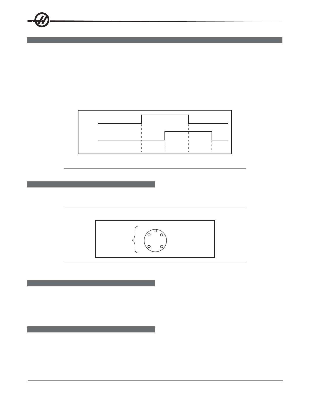
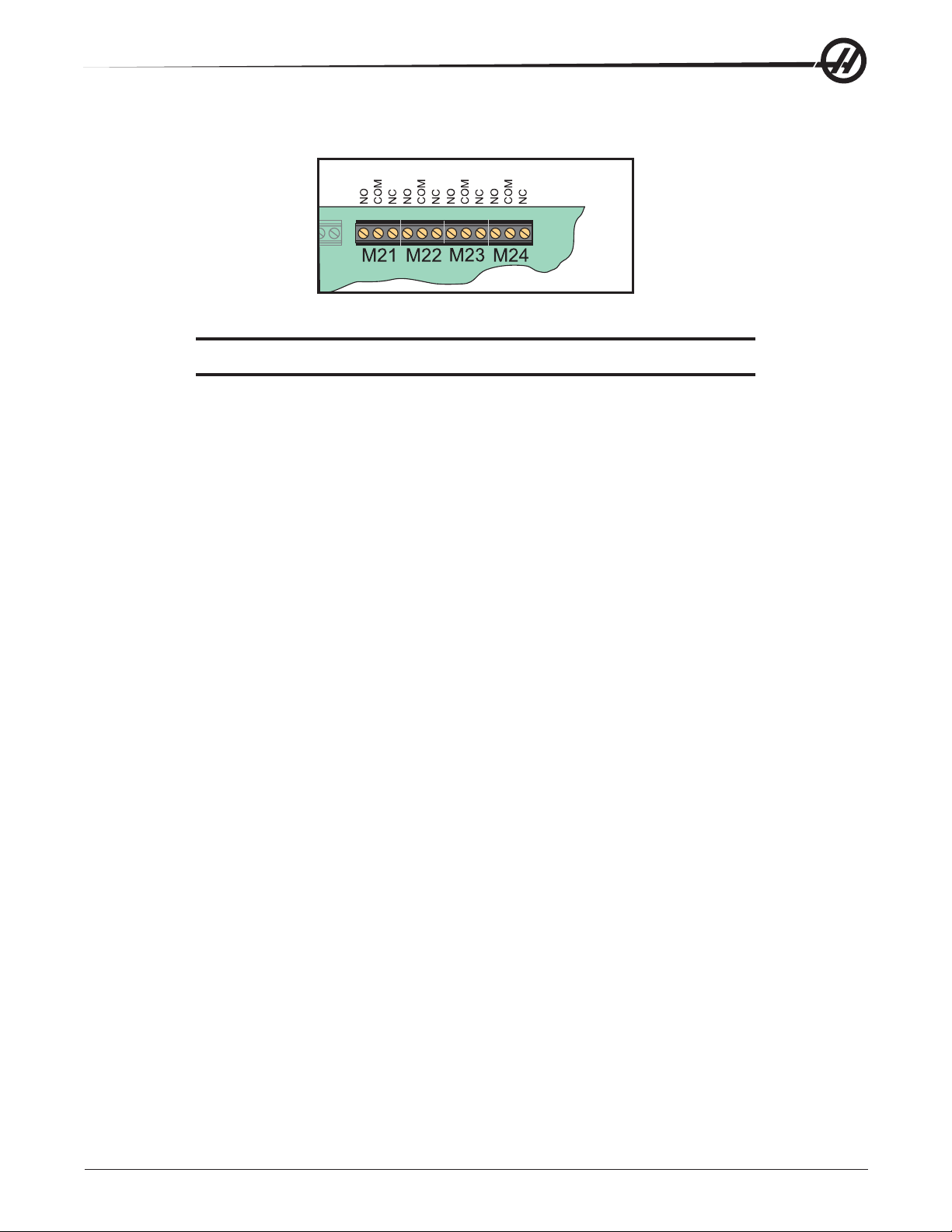
SPARE USER M CODE INTERFACE
The M code interface uses outputs M21-25 and one discrete input circuit. M codes M21 through M25 will
activate relays labeled M21-25. These relay contacts are isolated from all other circuits and may switch up to
120V AC at three amps. The relays are SPDT (Single Pole Double Throw).
WARNING!
Power circuits and inductive loads must have snubber protection.
The M-FIN circuit is a normally open circuit that is made active by bringing it to ground. The one M-FIN applies
to all of the user M codes.
The timing of a user M function must begin with all circuits inactive (open). The timing is as follows:
M21
M-FIN Discrete
Input 1009
CNC is:
Running Waiting
for M-fin
.05 ms
delay
Waiting for
end M-fin
Running
The Diagnostic Data display page may be used to observe the state of these signals.
NOTE: See the 8M option section for more details.
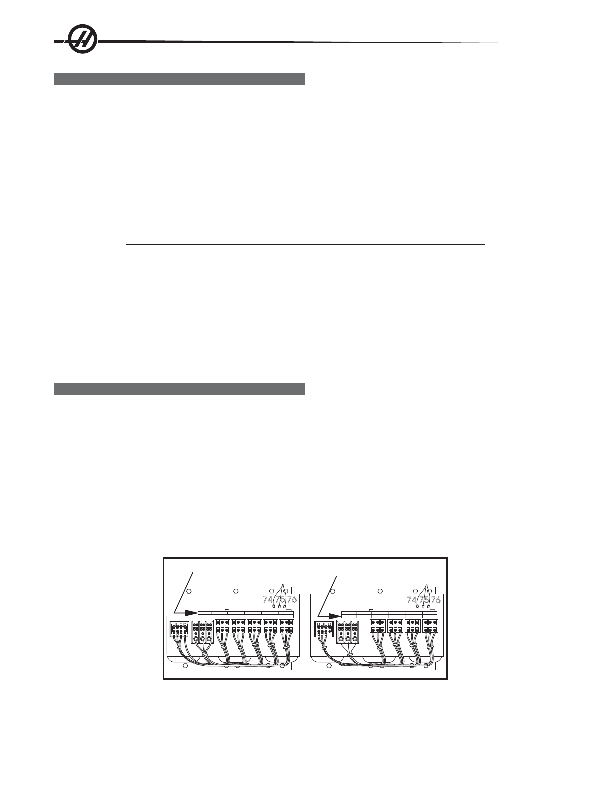
M FUNCTION RELAYS (M-FIN)
The I/O PC board has relays that are available to the user. M21 is already wired out to P12 at the side of the
control cabinet. This is a four-pin DIN connector and includes the M-FIN signal.
NOTE: Refer to Diagnostic Data for specific machine Inputs and Outputs.
3
M-Code
Output Relay
Normally Open
4
NOTE: Some or all of the M21-25 on the I/O PCB may be used for factory installed
options. Inspect the relays for existing wires to determine which are in use.
1 M-FIN, Input Signal
2 Input GND
M-FIN DISCRETE INPUT
The M-FIN discrete input is a low voltage circuit. When the circuit is open, there is +12V DC at this signal.
When the line is brought to ground, there is about 10 milliamps of current. M-FIN is discrete input 1009 and is
wired from input 1009 on the I/O PCB (usually P10). The return line for grounding the circuit should come from
that PCB. For reliability, these two wires should be routed in a shielded cable where the shield is grounded at
one end only. The diagnostic display shows a “1” when the circuit is open and a “0” when it is grounded.
WIRING THE RELAYS
The relays are marked on the I/O PCB, with their respective terminals forward of them. If the optional 8M relay
board is installed, the connections on the I/O PCB are to be left unused, since they are replaced by the relays
on the optional board. Refer to the figure, and the Probe Option figure in the Electrical Diagrams section for the
terminal labeling.
28
Electrical Service
96-0284 rev A June 2006
Page 30
WARNING!WARNING!
WARNING!
WARNING!WARNING!
Power circuits and inductive loads must have snubber protection.
I/O PCB Relays
CAUTION! If a screw terminal is already in use, do not connect anything else to it.
96-0284 rev A June 2006
Electrical Service
29
Page 31

LIMIT SWITCHES
X, Y, Z Travel Limit Switches
The machine zero position is defined by a limit switch for each of the X, Y, and Z axes. After the search for
machine zero has been completed, these switches are used to limit travel in the positive direction. Travel in the
negative direction is limited by stored stroke limits. It is not normally possible to command the servo axes past
the machine zero as servo travel lookahead will decelerate and stop each motor prior to exceeding the stroke
limits. All limit switches are wired through connector P5 on the side of the control cabinet. P5 also contains the
wiring to the lubrication pump and an alternate connection to the door open switches.
Prior to performing a Power Up/Restart or an Auto All Axes operation, there are no travel limits. You can jog into
the hard stops in either direction for X, Y, or Z. After a Zero Return has been performed, the travel limits will
operate unless an axis hits the limit switch. When the limit switch is hit, the zero returned condition is reset
and an Auto All Axes must be done again to ensure you can still move the servo back away from it.
The limit switches are normally closed. When a search for zero operation is being performed, the X, Y, and Z
axes will move towards the limit switch unless it is already active (open); then move away from the switch until
it closes again; then continue to move until the encoder Z channel is found. This position is machine zero.
On some mills, the auto search for zero in the Z-axis is followed by a rapid move from the limit switch position
down to the tool change position, making the Z-axis a little different from the other axes. The position found
with the limit switch is not machine zero but is the position used to pull tools out of the spindle. Machine zero
for Z is below this by Parameter 64. Be careful during the Z zero search and stay clear of that rapid move.
What Can Go Wrong With Limit Switches?
If the machine is operated without connector P5, a Low Lube and Door Open alarm will be generated. In
addition, Home search will not stop at the limit switch and will instead run into the physical stops on each axis.
If the switch is damaged and permanently open, the zero search for that axis will move in the negative direction
at about 0.5 in/min until it reaches the physical travel stops at the opposite end of travel.
If the switch is damaged and permanently closed, the zero search for that axis will move at about 10 in/min in
the positive direction until it reaches the physical stops.
If the switch opens or a wire breaks after the zero search completes, an alarm is generated, the servos are
turned off, and all motion stops. The control will operate as though the zero search was never performed. Reset
can be used to turn servos on, but you can jog that axis only slowly.
Clamp/Unclamp Switches
There are two switches used to sense the position of the turret or tool clamping mechanism. They are both
normally closed and one will activate at the end of travel during unclamping and the other during clamping.
When both switches are closed, it indicates that the turret or drawbar is between positions.
The diagnostic display can be used to display the status of the relay outputs and the switch inputs.
Door Hold Switch
The switch is normally closed. When the door opens, the switch opens and the machine stops with a “Door
Hold” function. When the door is closed again, operation continues normally.
If the door is open, you will not be able to start a program. Door hold will not stop a tool change operation, will
not turn off the spindle, and will not turn off the coolant pump. The door hold function can be temporarily
disabled with Setting 51, but this setting will return to Off when the control is turned off.
Tool #1 Sense Switch
The tool rotation turret has a switch that is activated when tool one is in position or facing toward the spindle.
At Power On this switch can indicate that tool #1 is in the spindle. If this switch is not active at power-on, the
first tool change will rotate the turret until the switch engages and then move to the selected tool. The diagnos-
tic display will show the status of this input switch as “Tool #1”. A “1” indicates that tool #1 is in position.
30
Electrical Service
96-0284 rev A June 2006
Page 32

Tool Changer Geneva Wheel Position Mark
The turret rotation mechanism has a switch mounted so that it is activated for about 30o of travel of the Geneva
mechanism. When activated, this switch indicates that the turret is centered on a tool position. This switch is
normally closed. The diagnostic display will show this status of this input switch as “TC MRK”. A “1” indicates
the Geneva wheel is in position.
Tool Changer Shuttle In/Out Switches
Two switches are used to sense the position of the tool changer shuttle and the arm that moves it. One switch
is activated when the shuttle is moved to full travel inward and one is activated when it is in full travel outward.
These switches are normally closed, so that both are closed between in and out. The diagnostic display will
show the status of the input switch. A “1” indicates the associated switch is activated or open.
Transmission High/Low Gear Position Switches
On machines with a two-speed transmission, there are two switches in the gearbox used to sense the position
of the gears. One switch indicates High by opening and the other indicates Low by opening. Between gears,
both switches are closed, indicating a between-gear condition. The diagnostic display shows the status of
these switches and the Curnt Comds display shows which gear is selected. If the switches indicate that the
gearbox is between gears, the display will indicate “No Gear”.
NOTE: The Transmission High/Low Gear Position Switches are located at the bottom
of the Gearbox Assembly and are extremely difficult to reach. Removal of this
assembly is necessary to replace these switches. See Mechanical Service,
for Spindle Motor and Transmission removal.
96-0284 rev A June 2006
Electrical Service
31
Page 33

DIAGNOSTIC DATA
The Alarm Msgs display is the most important source of diagnostic data. At any time after the machine
completes its power-up sequence, it will either perform a requested function or stop with an alarm. Refer to the
alarms list for, their possible causes, and some corrective action.
If there is an electronics problem, the controller may not complete the power-up sequence and the monitor will
remain blank. In this case, there are two sources of diagnostic data; these are the audible beeper and the
LEDs on the processor PCB. If the audible beeper is alternating a ½ second beep, there is a problem with the
main control program stored in EPROMs on the processor PCB. If any of the processor electronics cannot be
accessed correctly, the LEDs on the processor PCB will or will not be lit.
If the machine powers up but has a fault in one of its power supplies, it may not be possible to flag an alarm
condition. If this happens, all motors will be kept off and the top left corner of the monitor will display a Power
Failure Alarm message, and all other functions of the control will be locked out.
When the machine is operating normally, a second push of the Param/Dgnos key will select the diagnostics
display page. The Page Up and Page Down keys are then used to select one of two different displays. These
are for diagnostic purposes only and the user will not normally need them. The diagnostic data consists of 32
discrete input signals, 32 discrete output relays and several internal control signals. Each can have the value of
0 or 1. In addition, there are up to three analog data displays and an optional spindle rpm display . Their number
and functions are:
DISCRETE INPUTS/OUTPUTS (LATHE)
Discrete Inputs
# Name # Name
1000 Tool Turret Unlock 1016 Spare
1001 Tool Turret Lock 1017 Spare
1002 Spare 1018 Spare
1003 Low Coolant 1019 Spare
1004 Automatic Door 1020 Low hyd pressure
1005 Spindle In Hi Gear 1021 T.S. Foot Switch
1006 Spindle In Low Gear 1022 Probe Not Home
1007 Emergency Stop 1023 Spare 2b
1008 Door Switch 1024 Tool Unclamp Rmt*
1009 M Code Finish 1025 Low Phasing 115V
1010 Over Voltage 1026 B F End of Bar
1011 Low Air Pressure 1027 Bar Feeder Fault
1012 Low Lube Press. 1028 Ground Fault
1013 Regen Overheat 1029 G31 Block Skip
1014 Spare 1030 B F Spindle Intlk
1015 Spare 1031 Conveyr Overcrnts
32
Electrical Service
96-0284 rev A June 2006
Page 34

Discrete Outputs
# Name # Name
1100 Hyd Pump Enable 1116 Move Spigot CW
1101 Spare 1117 Move Spigot CCW
1102 Spare 1118 Pal Ready Light
1103 Spare 1119 T.S. High Pressure
1104 Spindle Brake 1120 Tool Turret Out
1105 Coolant Pump on 1121 T.S. Reverse
1106 Power Off 1122 T.S. Forward
1107 Way Lube Pump 1123 (CE) Door Locked
1108 SB Motor Load PR 1124 M21 (Auto Door Clutch)
1109 SB Motor Load Bar 1125 M22 (Parts Catcher)
1110 Auto Door Open 1126 M23 (C Axis Engage)
1111 Auto Door Close 1127 HPC Coolant
1112 Spindle Hi Gear 1128 Green Beacon On
1113 Spindle Low Gear 1129 Red Beacon On
1114 Unclamp Chuck 1130 Enable Conveyor
1115 Lock Spindle 1131 Reverse Conveyor
The second page of diagnostic data is displayed using the Page Up and Page Down keys. It contains:
Inputs 2
X-axis Z Channel X Motor Over Heat
Y-Axis Z Channel Y Motor Over Heat
Z-axis Z Channel Z Motor Over Heat
A-axis Z Channel A Motor Over Heat
B-axis Z Channel B Motor Over Heat
C-axis Z Channel C Motor Over Heat
X Home Switch X drive fault
Y Home Switch Y drive fault
Z Home Switch Z drive fault
A Home Switch A drive fault
B Home Switch B drive fault
C Home Switch C drive fault
X Cable Input S Z CH Spindle Z Channel
Y Cable Input
Z Cable Input
A Cable Input
B Cable Input
C Cable Input
The Temp-Track option displays the X and Z ballscrew temperatures on the Inputs2 diagnostics screen just
above “SP Load” when Parameter 266 or 268 bit 9 “Temp Sensor” is set to 1. The following inputs and outputs
pertain to the Haas Vector Drive. If it is not enabled, a value of * is displayed. Otherwise, it displays a 1 or 0.
Haas Vector Drive
Name Name
Spindle Forward Spindle Fault
Spindle Reverse Spindle Locked
Spindle Lock Spindle Cable Fault
Spindle At Speed Spindle Overheat
Spindle Stopped
96-0284 rev A June 2006
Electrical Service
33
Page 35

Analog Data
Name Description
SP LOAD Spindle load in %
SP SPEED Spindle rpm CW or CCW
RUN TIME Total machine run time
TOOL CHANGES Number of tool changes
VER X.XXX Software version number
YY/MM/DD Today's date
MDL SL-__ Model number
DC BUSS Mocon II
DISCRETE INPUTS/OUTPUTS (MILLS)
# Name # Discrete Input Name
1000 TC Changer In/SMTC Pocket Down 1023 Spare 3/APC Pin Clr #2
1001 TC Changer Out/SMTC Pocket Up 1024 Tool Unclmp Rmt*
1002 Tool One In Pos. 1025 Spare
1003 Low TSC Pressure 1026 Spare 3A/APC Pal #2 Home
1004 Tool In Position 1027 Spare 3B/APC Pal #1 Home
1005 Spindle High Gear 1028 Ground Fault
1006 Spindle Low Gear 1029 G31 Block Skip
1007 Emergency Stop 1030 Spigot Position
1008 Door Safety Switch 1031 Conveyr Overcrnt
1009 M Code Finish*/APC: APC Pal Clamp 1032 Spare 4A
1010 Over Voltage (Mini-Mill - P.S. Fault) 1033 Spare 4B
1011 Low Air Pressure 1034 Spare 5A
1012 Low Lube Press. 1035 Spare 5B
1013 Regen Over Heat 1036 Spare 6A
1014 Drawbar Open 1037 Spare 6B
1015 Drawbar Closed 1038 Spare 7A
1016 Spare 1039 Spare 7B
1017 Spare 1040 Spare 8A
1018 Spare 1041 Spare 8B
1019 Spare 1042 Spare 9A (SMTC: Motor stop)
1020 Low Trans Oil Prs 1043 Spare 9B (SMTC: Origin)
1021 Spare 1/APC Door 1044 Spare 10A (SMTC: Clamp / Unclamp)
1022 Spare 2/APC Pin Clr #1 1045 Spare 10B
The inputs are numbered the same as the connections on the inputs printed circuit board. (*): active when = 0.
34
Electrical Service
96-0284 rev A June 2006
Page 36

# Discrete Output Name # Discrete Output Name
1100 Powered Servos 1120 Unclamp Pre-Chrg
1101 Spare 1121 HTC Shuttle Out (Air Drive Shuttle in/ APC Door)
1102 Spare 1122 Brake 5TH Axis
1103 Spare 1123 CE Door Lock
1104 Brake 4th Axis 1124 M21
1105 Coolant Pump On 1125 M22
1106 Auto Power Off 1126 M23 (Air Drive Shuttle: Move Shuttle Out)
1107 Spind. Motor Fan 1127 TSC Coolant
1108 Move T.C. In/APC Chain Dr Fwd 1128 Green Beacon On
1109 Move T.C. Out/APC Chain Dr Rev 1129 Red Beacon On
1110 Rotate T.C. CW 1130 Enable Conveyor
1111 Rotate T.C. CCW 1131 Reverse Conveyor
1112 Spindle Hi Gear 1132 M-fin
1113 Spindle Low Gear 1133 Probe
1114 Unclamp Tool 1134 spare
1115 Spare 1135 spare
1116 Move Spigot CW 1136 spare
1117 Move Spigot CCW 1137 spare
1118 Pal Ready Light 1138 spare
1119 TSC Purge 1139 spare
NOTE: The following inputs and outputs change for machines equipped with an APC.
# Discrete Output Name # Discrete Output Name
1021 APC CE Door 1108 APC Chain Drive Forward
1022 APC Pin CLR #1 1109 APC Chain Drive Reverse
1023 APC Pin CLR #2 1121 PAL Clamp
1026 APC PAL #2 Home 1122 Door
1027 APC PAL #1 Home 1125 APC Motor
1046 APC Door Closed 1126 Beeper
1047 Door Open 1137 APC Chain Drive Power Enable
1048 APC Pallet Clamped 1138 Air Blast
1101 Pallet Clamped 1139 APC Beeper
The second page of diagnostic data is displayed using the Page Up and Page Down keys. It contains:
Inputs 2
Name Name Name
X Axis Z Channel X Overheat X Cable Input
Y Axis Z Channel Y Overheat Y Cable Input
Z Axis Z Channel Z Overheat Z Cable Input
A Axis Z Channel A Overheat A Cable Input
B Axis Z Channel B Overheat B Cable Input
X Home Switch X Drive Fault Spindle Z Channel
Y Home Switch Y Drive Fault
Z Home Switch Z Drive Fault
A Home Switch A Drive Fault
B Home Switch B Drive Fault
96-0284 rev A June 2006
Electrical Service
35
Page 37

The following inputs and outputs pertain to the Haas Vector Drive. If it is not enabled, these will display a value
of *. Otherwise, it will display a 1 or 0.
Spindle Forward
Spindle Reverse
Spindle Lock
Spindle at Speed*
Spindle Stopped
Spindle Fault
Spindle Locked
Spindle Cable Fault
Spindle Over Heat
The following Discrete Inputs/Outputs 2 are available when Parameter 278 SMNT bit 1,2 or 3 (Side-Mount Tool
Changer) is set and Parameter 209 MCD RLY BRD (M-Code relay board) is On.
Discrete Inputs 2
Name Name
Spare Input 4A Spare Input 8A
Spare Input 4B Serp. Shot Pin*
Spare Input 5A Motor Stop
Spare Input 5B Origin
Spare Input 6A Clamp/Unclamp
Spare Input 6B Serp. Cam Count
Spare Input 7A Spare Input 11A
Spare Input 7B Spare Input 11 B
Discrete Outputs 2
Name Name
Spare Output 32 Spare Output 44
Spare Output 33 Spare Output 45
Spare Output 34 Spare Output 46
Spare Output 35 Spare Output 47
Spare Output 36 Spare Output 48 (SMTC: Serp. ATC Enable)
TC MTR SW Spare Output 49 (SMTC: Serp. ATC Rev.)
Spare Output 38 Spare Output 50 (SMTC: Serp. Carsl CW)
Spare Output 39 Spare Output 51 (SMTC: Serp. Carsl CCW)
Spare Output 40 Spare Output 52 (SMTC: Serp. Carsl Ena.)
Spare Output 41 Spare Output 53
Spare Output 42 Spare Output 54
Spare Output 43 Spare Output 55
Analog Data
Name Description
DC BUSS Voltage from Haas Vector Drive (if equipped)
uP TEMP Displayed when Parameter 278 bit "µP Encl Temp" is set to 1)
SP LOAD Spindle load in %
SP SPEED Spindle rpm CW or CCW
RUN TIME Machine total run time
TOOL CHANGES Number of tool changes
VER X.XXX Software version number
MOCON MOCON software version
YY/MM/DD Today's date
MDL HS__ Machine model
FV 2 11.0004 Floppy version (Ethernet Firmware)
36
Electrical Service
96-0284 rev A June 2006
Page 38

PCBS, CABLE LOCATIONS, AND DIAGRAMS
Shown below are three types of commonly used cable connectors. They are shown as seen when plugged
into the pc board. These diagrams are to aid in locating the pins for trouble shooting.
Red Wire
1
2
3
1
2
3
4
5
6
1
2
3
4
1
2
3
4
5
6
6
7
Friction Lock
2
4
6
8
10
12
14
16
1
3
5
7
9
11
13
15
17
19
21
23
25
27
29
31
33
1
2
3
4
5
1
2
3
4
5
6
7
8
Red Wire
1
3
5
7
9
11
13
15
Ribbon Cables
2
4
6
8
10
12
14
16
18
20
22
24
26
28
30
32
34
1
2
3
4
5
6
1
2
3
Mini Fit
1
2
3
3
4
4
5
6
7
8
1
2
1
2
3
4
NOTE: The numbering sequence is the same regardless of the number of pins.
Pin 5
Pin 1
Connection Example
96-0284 rev A June 2006
Electrical Service
37
Page 39

MICROPROCESSOR PCB
U1 U2
U7
C6
1MB 16MB
U3
U11
J6
512K
R52
R53
S2
9.6K
BAUD
38.4K
U8
C5
128K
RUN
BT1
U24
Y1
850A 850
C9
D1
D2
D3
D4
D5
D6
D7
D8
U15
U7
J4J5
C39
C37
C38
C40
FLASHMEMORY
U1 U2 U3
J6
U8
BT1
S2
9.6K
38.4K
RUN
BT2
BAUD
C7
D1
RUN
D2
PGM
D3
CRT
D4
MSG
D5
SIO
D6
POR
D7
HALT
D8
+5V
Y1
J4
850
U22
J5
850A
C46
C43
C45
C47
C82
U38
U41
U37
C76
J1 J2
ADDRESS BUS DATABUS
64MB
DRAM
COLDFIRE 266 MHZ
PROCESSOR CHIP
(Co-processor built-in)
U39
3.3V DC
BATTERY
J7
U16
U17
LINE 1:
LINE 2:
LINE 3:
SUBASSY
U53
C75
C74
J3
U58
C92
J1 J2
BATTERY BACKED UP
RAM 1MB OR 16MB
ADDRESSBUS
U59
FLASH
RAM
J4
J5
D1
D2
D3
D4
STATUS
D5
D6
D7
D8
INTERFACE DATA
850
850A
DATABUS
LEDS
KEYBOARD
AUX PORT
U43
LINE 1:
LINE 2:
LINE 3:
U60
PAL4.9x
C91
C94
J3
38
J1 J2
Electrical Service
DATA BUSADDRESS BUS
J3
J3
LOW VOLTAGE
#860 CABLE
96-0284 rev A June 2006
Page 40

ÖÖ
PLUG # CABLE # SIGNAL NAME
Ö TO
ÖÖ
Ö LOCATION PLUG #
ÖÖ
ÖÖ
J1 ADDRESS ADDRESS BUSS VIDEO-MOCON-MOTIF ____
J2 DATA DATA BUSS VIDEO-MOCON-MOTIF ____
J3 860 LOW VOLTAGE <FROM>PSUP PCB ____
J4 PORT 1 850 SERIAL PORT #1 KEYBOARD INT. ____
J5 PORT 2 850A SERIAL PORT #2 AUX PORT AUX SERIAL PORT ____
J6 AUX BATTERY INPUT
SERVO SYSTEM BLOCK DIAGRAM
LOW
VOLTAGE
POWER SUPPLY
LV HV
CURRENT
COMMAND
ENCODER
CURRENT
COMMAND
ENCODER
+/- 12V DC
VECTOR
DRIVE/HIGH
VOLTAGE
POWER SUPPLY
320V DC
BRUSHLESS
SERVOAMP
BRUSHLESS
SERVOAMP
MTR PWR
MTR
PWR
BRUSH
CONVERTER
BOX
AXIS
CABLE
MTR PWR
ENCODER
BRUSHLESS
AXIS
MOTOR/
ENCODER
TYPICAL
BRUSH
AXIS
MOTOR/
ENCODER
(Opt)
MOCON BOARD
96-0284 rev A June 2006
C-AXIS COMMAND
C-AXIS ENCODER
SPINDLE ENCODER
VECTOR DRIVE
OR
LARGE AMP
Electrical Service
DELTA-
WYE
(Opt)
TYPICAL
SPINDLE
MOTOR
MOTOR/
ENCODER
(Opt)
SPINDLE
ENCODER
39
Page 41

BRUSHLESS SERVO AMPLIFIER (P/N 93-5550C)
CURRENT COMMAND
LOW VOLTAGE POWER
NOTE: Newer amplifiers do not have a blown fuse indicator.
SERVO DRIVE
( FROM MOCON)
(INPUT)
POWER TO
SERVO MOTOR
335VDC
(FROM HAAS
VECTOR DRIVE)
BLOWN FUSE
INDICATOR
PLUG # CABLE # SIGNAL NAME Ö TO Ö LOCATION PLUG #
X AXIS AMP
LVPS PLUG 570 LOW VOLTAGE L. V. POWER SUPPLY ——TB A, B, C ——- MOTOR DRIVE X SERVO MOTOR ——SERVO PLUG 610 X DRIVE SIGNAL MOCON PCB P2
TB -HV +HV ——- 335VDC SPINDLE DRIVE ——-
Y AXIS AMP
LVPS PLUG 580 LOW VOLTAGE L. V. POWER SUPPLY ——TB A, B, C ——- MOTOR DRIVE Y SERVO MOTOR ——SERVO PLUG 620 Y DRIVE SIGNAL MOCON PCB P3
TB -HV +HV ——- 335VDC SPINDLE DRIVE ——-
Z AXIS AMP
LVPS PLUG 590 LOW VOLTAGE L. V. POWER SUPPLY ——TB A, B, C ——- MOTOR DRIVE Z SERVO MOTOR ——SERVO PLUG 630 Z DRIVE SIGNAL MOCON PCB P4
TB -HV +HV ——- 335VDC SPINDLE DRIVE ——-
A AXIS AMP
LVPS PLUG 600 LOW VOLTAGE L. V. POWER SUPPLY ——TB A, B, C ——- MOTOR DRIVE A SERVO MOTOR ——SERVO PLUG 640 A DRIVE SIGNAL MOCON PCB P5
TB -HV +HV ——- 335VDC SPINDLE DRIVE ——-
40
Electrical Service
96-0284 rev A June 2006
Page 42

SYSTEM BLOCK DIAGRAM - HIGH/LOW VOLTAGE
INPUT VOLTAGE
195-260V AC
(353-480V AC)
230V AC
MAIN
POWER
DISTRIBUTION
12V DC
115VAC
195-260V AC
(353-480V AC)
INPUT
115VAC
230V AC
MAIN
TRANSFORMER
OPERATOR
PENDANT
115VAC
115VAC
230V AC
TSC
OPTION
(Vert)
M CODE
RELAY
BOARD
(Opt)
MICRO
PROCESSOR
(CNC UNIT)
DISCRETE
INPUTS
AND
OUTPUTS
DC
MTR DRV
BOARD
(Opt)
LOW VOLTAGE
CMDS
STATUS
230V AC
COOLANT PUMP &
CHIP CONVEYOR
CMDS
FAULTS
POSITION DATA
HOME
SWITCH
(Vert &
Lathe)
SENSORS
CMDS
VIDEO, KEYBOARD, AND JOG
(FLOPPY DRIVE & RJH)
BRUSHLESS
SERVO
AMPLIFIERS
(X, Y,Z, A, 5TH
TC (SS) OPTION
(Vert)
PWR
SPINDLE COMMANDS
SPINDLE ENCODER
SERVO MOTORS
335V DC
(325V DC
Horiz)
HAAS
VECTOR DRIVE
EXCESS PWR
CONTACTORSCOIL
REGEN
ASSY
LIMIT SWITCHES
GEAR BOX SWITCHES
TOOL CHANGER/OVERHEAT SENSORS/
LOW LUBE/LOW COOLANT/SOLENOIDS
230V AC
SP
PWR
SPINDLE MOTOR
CHIP CNVYR
BOARD
(Opt)
CHIP CNVYR
MTRS
(Opt)
PWR
PWR
WYE-DELTA
CONTACTORS
(Opt)
96-0284 rev A June 2006
Electrical Service
41
Page 43

POWER PCB
P5
P11
P3
P7
P6
P2
P12
P35 P34 P8 P33 P28
MCD 1
MCD 2
LVINPUT
GND
SW DOOR FAN
MONITOR
PROBE PS
DELTA-WYE
SERVO FAN
LOW VOLTPS
90A
90A
90A
90A
90A
90C
94/N
AC GROUND
90C
P13
GND
+12V
P1
96
95
+12V
LE2
+12V
115VINPUT
115VSPARES
P14
GND
GND
+5V
+5V
-12V
+12V
Z3
TS1
90C90C 90C
Z4
LE3
-12V
MAIN 115V XFRMR
ON ON ON ON ON
10A 115V
MAIN
XFRMR
CB2
90C 90C
P15 P16
P27
PHASE DETECT
(FOR 3 PHASE ONLY)
MOCON 2
-12V
P17
MOTIF
GND
GND
+5V
+12V
Z1
+5V
P18
AMPS
GND
+12V
-12V
GFI
7A 115V
GFI
CB6 CB3 CB5
3PH 115VTO IOPCB
P19
IOPCB
GND
GND
+5V
GND
+12V
92A
GND
+12V
GND
+5V
COOLANT PUMP
10A 230V
COOLANT PUMP
WORKLIGHT
GFI/
+5V
GND
+12V
P30
LE1
-12V
90
P36
FAILPASS
NE6
NE5
TSC COOLANT PUMP
930
P20
P25
71 73
F1
NE1
10A 230V
TSC COOLANT PUMP
POWER SUPPLY ASSY
COOLANT/TSC
1/2A 250V
NE3
PSUP-K
P24 P4
SEC
PRI
TO T5
F3
230V IN
P9
CHIP CONVEYOR
5A 230V
CHIP CONVEYOR
CB4
160
CHIPC 230V
P21
170
740
P10
P23
AUTO OFF/CONTACTOR
ON/OFF
P22
PLUG # CABLE # SIGNAL NAME Ö TO Ö LOCATION PLUG#
P1 94-96 115 INPUT CNC Unit Fan
P2 90C 115VAC LVPS
P3 90A 115VAC Probe PS
P4
P5 90B 115VAC Switch Door Fan
P6 90A 115VAC Servo Fan
P7 90A 115VAC Delta-Wye
P8 +12/-12/+5 VDC In From LVPS
P9 70 +12/-12/+5 VDC In
P10 90B 115VAC Door Fan
P11 90A 115VAC Monitor
P12 90C 115VAC spare
P13 90C 115VAC spare
P14 90C 115VAC spare
P15 90C 115VAC spare
P16 90C 115VAC spare
P17 90C 115VAC spare
P18 860 115VAC Amps
P19 90 3PH 115VAC I/O PCB P56
P20 930 230V CLNT PUMP/TSC I/O PCB P44
P21 160 Chip Conv. 230V 3PH I/O PCB P39
P23 170 Auto Off/Contactor Contactor K1 I/O PCB P42
P22 740 On/Off Front Panel
P24 T5 Main Cont Frmr To T5
P25 71, 72, 73 230VAC IN From Contactor K1
P27 860 +12/+5 VDC I/O PCB P60
P28 860 +12/+5 VDC Motif PCB P15
P30 860 +12/-12/+5 VDC spare
P33 860 +12/-12/+5 VDC Mocon 2 PCB P15
P34 860A +12 VDC SMTC PCB P2
P35 860 +12 VDC MCD Relay PCB P2
P36 92A Worklight
42
Electrical Service
96-0284 rev A June 2006
Page 44

OFFICE MILL POWER SUPPLY
P8
C10
DZ1
LE1
HIGH
VOLTAGE
PRESENT
BL 320V PS
R21
C8
C13
DZ3
CR3
Q2
U2
CR2
VR1
C7
C9
P7
230VAC
P1
CR7
R23
320VDC
P2
K1
CR12
U3
CR10
TP1
320VRTN
C19
TP2
LE2
FAULT
JP1
C11
CR5
CR4
T1
U4
C14
C12
DZ4
CR6
C31
R5
CR9
U9
C28
U8
U7
VOLTMON
P6
FAULT
P4
U6
U5
970
ISP
Q1
R14
R7
CR1
REGEN
CR18
DZ2
R1
P5
C3
P5
860A+12V
C1
Q3
U1
P3
TP3
12VRTN
PLUG # CABLE # LOCATION PLUG#
P1 32-5827A Ofice machine main transformer LV 1PH Main transformer
P2 N/A
P3 33-0982 Cable 860A +5/+12 GND I/O PCB I/O PCB P60
P4 33-4150 Cable 970 Vector Drive Over Volt I/O PCB P11
P5 32-7044 40 Ohm Regen Resister
P6 33-9861 Cable Volt Monitor MOCON P17
P7 33-0167A Cable 230V in to BL320VP PSUP (34-4075K) P10
P8 33-0492 Cable 320VDC to amp 320VDC AMP TB
96-0284 rev A June 2006
Electrical Service
43
Page 45

I/O PCB REV. U
P1
P2
P3
P4
P5
P6
P7
P8
P10
P11
P12
P13
P14
P15
P16
P17
P18
P19
P20
P21
P22
P23
P24
P25
P26
P27
P28
P71
P29
P30
TB2
NSK
P75
C59
*
M26
AIRBLAST
BEEPER
PALCW
PALCCW
AIRDOOR
OILEXTEND
260
PALRDY
860A
P77
K2
P79
P80
T1
CR10
K18
P35A
200
SPIGOT
P35P34P36
AXISBRAKE
P60
PROBE
P78
+25V
CR34
CR5
AGND
CR11
K17
CHIPCEN/REV
P57
K1
C69
TP4
Z9
R51
CR25
140A
P37
C9
Z6
CHIPC REV
M21
CR12
P63
P74
P66
P67
P69
P76
DOORLOK
Q21
230
5'THBRAKE
P31
M22
K33
M21
P61
540
FROMMOCON
Q33
Q32
550
M26
M27
P68
220
1160
HTCSHUT
PRE-CHG
5'THBRK
K34
M22
CR13
310
TSCPURGE
SPIGCCW
PALRDY
SPIGCW
Q20
250
HTCSHUT
P32
TB1
M23
K35
M23
CR14
P62
J9
(INPUTMUX
DISABLE)
SPARE
AIRBLAST
BEEPER
PALCW/CCW
AIRDOOR
OILSQUIRT
GREEN
RED
P33
Q23
C66
TSCPURGE
K36
M24
CR15
540A
TOMCD RLY
P70
530
Q18
270
NC COM
M24
CR33
NO
M25
K37
M25
CR9
Z10
CR1
U73
L1
Q44
Q30
Q31
Q28
Q29
Q27
Q46
Q7
Q17
280
BEACON
140B
CHIPCOC
820B
TCS TATSH IN/OUT
820
P2A
LOTSC
P72
900
ESTOP-D/E
770C/D
E-STOP-A/B/C
770
P81
770A
770B
P9
DOOR-A
1050
1050A
DOOR-B
M-FIN
100
970
LOAIR/OIL LO LUBOVERV
950
960
OVERH
830
SPHD STAT SPARE5 SPARE1
890
780
410
790
REMUNCL A/BSPARE2
190
190A
240
SKIPSPARE3
1070
420
SPARE6SPARE4
440
450
SPARE8SPARE7
460
P82
REM
470
SPARE9
SQUIRT
UNCL
LOOIL
190
A/B
SPARE10
480
PHLS
Q22
CEDOOR LOCK-A/B
1040/A
R3
CR24 CR23 CR21 CR22 CR20
K9
K10
CR2 CR3 CR4 CR6
C70
CR35
I/OPCB-U 3-AUGUST-05
IOPCB - U CCA
CHIPCOC ADJUST
R122
Z8
R127
140
CHIPCONVEYOR
P38
P58
CR7
K38
P64
P65
CHIPCEN
CR16
P59
APCMTR
TCMOTORS
810
Q39
R4
Q40
R145
D10
R66
CR8
R52
R146
R310
REMVTO ISOL 115
J2
CR19 CR17 CR18
K11
K12
R311
R7
R44
520
TCIN
TCOUT
TCCW
TCCCW
HIGHGEAR
LOWGEAR
UNCLAMP
DELTA-WYE
SERVOBRK
PALUP
SPARE1
SPARE2
510
4THBRK
COOLANT
AUTOOFF
SPINFAN
TSC COOL
MILL
LATHE
J1
C15
Q3
K32
C14
Q4
160
230VAC3PH
R42
R5
D1
D18
D17
D21
D20
C46
Q19
P54
880B
Q13
Q14
P53
Q15
P53A
Q16
Q5
Q41
P47
Q42
Q2
Q10
P50
Q11
P48
Q45
Q36
Q6
Q43
Q8
Q9
Q12
Q1
D19
115V3PH
P56
90
D22
GBI/F
SPHD SOLENOIDS
P55
880C
350
880A
DELTA-WYE
SPARE
P52
710
PALUP
430
P51
SERVOBRK-A/B
350A
P49
4'THBRAKE
P46
390
TSCENABLE
TSCO/T
130
120
P73
COOLO/T
170
P42
AUTOOFF
K7
TSCCOOL
940A
P45
COOL/TSC230 IN
930
P44
COOLANT
940
P43
SPINFAN
300A
P41
LUBOIL PUMP
300
P40
P39
PLUG # CABLE # Ö TO Ö LOCATION PLUG #
P1 140B Chip Conveyor VB1/Gantry
P2 820B TC in/SMTC Pkt down
P2 (Lathe) 820B TT Unlock/Lock
P2A 820B Shuttle In/Out
P3 820 TC out/SMTC pkt up/Tool #1/TC mark
P3 (Lathe) 820 C-axis Engage/Disengage
P4 900 Low TSC press
P4 (Lathe) 900 Spare
P5 770 E-Stop Sw A
P6 770A E-Stop Sw B
P7 770B E-Stop Sw C
P8 1050 Door Open A
P9 1050A Door Open B
44
Electrical Service
96-0284 rev A June 2006
Page 46

PLUG # CABLE # Ö TO Ö LOCATION PLUG #
P10 100 M-Fin
P11 970 VD Over Volt VD J1
P12 950 Low Air/Low Oil/VB low chill pressure
P12 (Lathe) 950 Low Air/Hyd. pressure
P13 960 Low Lube
P14 830 Regen Overheat
P15 890 SPDB Open/Closed
P15 (Lathe) 890 Spare/Gearbox
P16 780 2nd VD OV/contactor On/counterbalance
P16 (Lathe) 780 Spare
P17 410 APC Door Open , VB Clamshell
P17 (Lathe) 410 TS Foot Sw/Sub Spndl Chuck Foot Switch
P18 790 APC Pin Clear - door open/closed
P18 (Lathe) 790 Probe Home
P19 190 Remote Unclamp Sw/Low phase
P19 (Lathe) 190 Chuck Unclamp Foot Sw/Low phase
P20 190A Remote Unclamp B
P20 (Lathe) 190A Not Used
P21 240 Spare 3, APC Pallet Home / Grnd fault/ pal up,dwn
P21 (Lathe) 240 BF Load Bar/Q/RPL: Cvr Opn/Slider Rtrct/Grnd Fit
P22 1070 Skip M22
P23 420 Spare 4, APC #2 pin clr / pal home
P23 (Lathe) 420 Spare (VTC: Pocket up/down/tool one/TC Mark)
P24 440 Spare 6, Auto Door Open / Spare
P24 (Lathe) 440 Auto Door Open
P25 450 Spare 7, APC #2 door open
P25 (Lathe) 450 Steady Rest Foot Switch
P26 460 Spare 8, APC #2 door closed
P26 (Lathe) 460 Apl Rotator Mark, Home (VTC: Low Way/SS Lube)
P27 470 Spare 9, SMTC mtr stop / SMTC origin/ /smtc cl uncl
P27 (Lathe) 470 Spare (VTC: Motor Stop/Origin/Cl/Uncl)
P28 480 Spare 10, APC door closed/Open / APC pal clamped
P28 (Lathe) 480 Spare 10 (VTC: Rem Uncl/SS DB Open/Closed)
P29 1040A CE Door LK
P29 (Lathe) 1040A Not Used
P30 1040 CE Door LK
P31 230 5th Axis Brake
P31 (Lathe) 230 T/S Fwd
P32 250 HTC shut, APC Door open, VR Shut In
P32 (Lathe) 250 T/S Rev
P33 260 TSC Purge
P33 (Lathe) 260 T/S Rapid (VTC: Purge)
P34 270 APC Pal Ready Lt
P34 (Lathe) 270 Spare (12V Output)
P35 (35A) 200 Spigot CW/CCW
P35 (Lathe) 200 Spare (VTC: Spigot CW/CCW)
P36 280 Beacon
P37 140A Chip Conv Enable
96-0284 rev A June 2006
Electrical Service
45
Page 47

PLUG # CABLE # Ö TO Ö LOCATION PLUG #
P37 (Lathe) 140A Not Used
P38 140 Chip Conveyor
P39 160 230V Coolant, Chip Conv Power PSUP P21
P39 (Lathe) 160 250V for Chip Conv.
P40 300 250V Oil Pump/Luber
P40 (Lathe) 300 SP Fan/Oil Pump/Luber
P41 300A SP Fan/Oil Pump
P41 (Lathe) 300A Not Used
P42 170 Auto Off PSUP P23
P43 940 Coolant Output
P44 930 250V TSC/Cool Input Power PSUP P20
P44 (Lathe) 930 230V for Coolant
P45 940A TSC Coolant TSC Cool. Out.
P45 (Lathe) 940A hp Coolant PSUP P20
P46 390 4th Axis Brake
P46 (Lathe) 390 Spin Brake
P47 350 Servo Brake Trans P6
P47 (Lathe) 350 Hyd Pump En
P48 120 Coolant Over Temp
P48 (Lathe) 120 Not Used (Jumper)
P49 350A Servo Brake, Hyd En Trans P4
P49 (Lathe) 350A Brake Release
P50 130 TSC Over Temp
P50 (Lathe) 130 Not Used (Jumper)
P51 430 Pallet up
P51 (Lathe) 430 APL Light/BF Extend Push
P52 710 Spare, APC #1 pal ready #1,2
P52 (Lathe) 710 APL Gripper Grip 1, Grip 2
P53 (P53A) 880C (880D) Wye-Delta Switch
P54 880B Gearbox, High/Low Gear
P55 880A Tool unclamp precharge (spindle head solenoids)
P55 (Lathe) 880A Chuck Unclamp/TT Out/MLB Fast Push
P56 90 115V 3ph power PSUP P19
P57 Haas P/N 33-0815B TC Jumper or SMTC brake resistor
P57 (Lathe) External TC Motor Resistor (Jumper)
P58 810A T.C. in/smtc ATC fwd / APC chn drv en/rev
P58 (Lathe) 810A Spare
P59 810 T.C. CW/ SMTC CRSL CW
P59 (Lathe) 810 Auto Dr, BF Id Bar/Q, APL Rtr (VTC: Car CW/CCW)
P60 860A +5/+12V Logic Pwr (LVPS) (I/O PCB) PSUP P27
P61 540 Outputs Cable 24-55 (I/0PCB) MOCON P14
P62 540A To 2nd M-code PCB MCD Relay P1
P63 550 Inputs Cable MOCON P10
P64 520 Outputs Cable 8-15 MOCON P12
P65 510 Outputs Cable 0-7 MOCON P11
P66 1100 (M27) Air Blast
P67 1110 (M28) Beeper
P67 (Lathe) M28 Sub Spin Chuck Sol
46
Electrical Service
96-0284 rev A June 2006
Page 48

PLUG # CABLE # Ö TO Ö LOCATION PLUG #
P68 310 Pallet CW/CCW, Auto Door open
P68 (Lathe) 310 APC Door open
P69 220 Air Door, Pckt Up/Down,VR Shtle Out, VB Clamshell
P69 (Lathe) 220 C-axis Engage
P70 530 Outputs Cable 16-23 MOCON P13
P71 500 N/A
P72 770C E Stop D/E
P73 Haas P/N 33-1966 TSC Enable
P74 M26 Spare
P75 710A NSK Spindle
P76 1160 Oil Squirt (MOM)
P77 1070 Probe
P78 350A Axis Brake
P79 350A Axis Brake
P80 N/A
P81 770C E-Stop
P82 1130 Oil Squirt (MOM) Low Oil
TB1 TB 12 x 200 (M21-24) M-Code Outputs (Probe, M-Fin, User Spare)
TB2 TB 3 x 200 (M25) M-Code Outputs
TB2 (Lathe) TB 3 x 200 (M25) User Spare
DISCRETE INPUTS
+12V
Typical Discrete Input Circuit
(C) = Switch Normally Closed; (O) = Switch Normally Open
MACRO CABLE HORIZONTAL VERTICAL LATHE
1000 820 P2/3 TC In (C) TC In (C) TT Unlock
SMTC Arm Mark (O) SMTC Pkt Dwn TL TC Home
EC-400 (O) SMTC Pkt Dwn
1001 820 P2/3 TC Out (C) TC Out (C) TT Lock
SMTC Shuttle Out (O) SMTC Pkt Up TL TC Mark
EC-400 (O) SMTC Pkt Up
1002 820 P3 PC DB Down (C) Tool #1 *C-axis Disengage
EC-400 (O) SMTC Tool #1 (O) SMTC Tool #1
1003 900 P4 Lo TSC Press Lo TSC Press Spare
EC-400 Lo TSC Press
1004 820 P3 PC Collet Down (C) TC Mark *C-axis Engage
EC-400 SMTC TC Mark (C) SMTC TC Mark
1005 890 P15 (O) High Gear (O) High Gear High Gear
1006 890 P15 (C) Low Gear (C) Low Gear Low Gear
1007 770 P5/6/7 E-Stop E-Stop E-Stop
96-0284 rev A June 2006
Electrical Service
47
Page 49

1008 1050 P8/9 (O) Door Open (O) Door Open Door Open
1009 100 P10 M-FIN M-FIN M-FIN
GR Plasma Confirm
1010 970 P11 Over Volt Over Volt Over Volt (not used)
1011 950 P12 Low Air Low Air Low Air
1012 960 P13 Low Way Lube Low Way Lube Low Way Lube
1013 830 P14 Overheat Overheat Overheat
1014 890 P15 (C) SP DB Open (C) SP DB Open Gearbox Low Oil
1015 890 P15 (C) SP DB Closed (C) SP DB Closed Spare
1016 890 P15 Spare 3rd DB Pos Sw Spare
EC-400 3rd DB Pos Sw
1017 780 P16 2nd VD OV 2nd VD OV Spare
1018 780 P16 Contactor On Contactor On Spare
1019 780 P16 Cntr Balance Cntr Balance Spare
1020 950 P12 Gearbox Low Oil Gearbox Low Oil Low Hydraulic
1021 410 P17 Air Door Sw (O) *TS Foot Sw
EC-400 TC Door Open (O) *Sub Spin Chck Ftsw
Old EC-300 Tool Door Open
GR Air Curtain APC
CE Door Open
1022 790 P18 PC Pallet CW (C) APC Pin Clr #1 (O) *Probe Home
EC-400 PP Pallet Lift (O) MD Op Door Open
1023 790 P18 PC Pallet CCW (C) APC Pin Clr #2
EC-400 PP Pallet Lower (O) MD Op Door Closed
1024 190 P19/20 PC Op Station Locked/ Rem Uncl (O) Chuck Uncl Foot Sw
Frnt Door
BF End of Bar
1025 500 P71 LO Phase LO Phase LO Phase
EC-400 Spare
1026 240 P21 PC Pallet Up (C) APC Pal #2 Home (C) BF Load Bar
BF Load Bar (C) Old MD Pal Up
(C) New MD Pal Unclamp
1027 240 P21 PC Pallet Down (C) APC Pal #1 Home BF Load Q
BF Load Q (C) Old MD Pal Down
EC-1600 Clamp Press
1028 Grnd Fault Grnd Fault Grnd Fault
1029 1070 P22/77 Skip Skip Skip
1030 200 P35 Possible P-Cool Spigot (C) BF End of Bar
EC-400 Spigot
1031 140B P1 Chip Conveyor Chip Conveyor Chip Conveyor
1032 420 P23 Mori Notch Pin In/ (C) APC #2 Pin Clr #1
SMTC Arm In
EC-400 Pallet Clamped
48
Electrical Service
96-0284 rev A June 2006
Page 50

MACRO CABLE HORIZONTAL VERTICAL LATHE
1033 420 P23 Mori Man Tool Rls In/ (C) APC #2 Pin Clr #2
SMTC Arm Out
EC-400 Pallet Unclamped
1034 420 P23 Mori Tool 1/SMTC Arm CCW (C) APC #2 Pal #2 Home
EC-400 Pallet Clamp Error
1035 420 P23 Mori TC Mark/SMTC Arm CW (C) APC #2 Pal #1 Home
1036 440 P24 Mori Arm In/SMTC Cage (O) Auto Door Open (O) Auto Door Open
Door Open
EC-400 SMTC Cage
Door Open
1037 440 P24 Mori Arm Out
1038 450 P25 Mori Arm CCW APC #2 CE Door Open *Steady Rest Ftsw
1039 450 P25 Mori Arm CW Spare for Foot Sw
1040 460 P26 Mori Slide 1/2 Way APC #2 Door Closed (O) APL Rotator Mark
1041 460 P26 Mori Slide Left APC #2 Door Open (O) APL Rotator Home
1042 470 P27 Mori Swing Spin/SMTC SMTC Motor Stop
Shuttle Mark
EC-400 SMTC Motor Stop
1043 470 P27 Mori Swing Mag/SMTC SMTC Origin
Slide at Chain
EC-400 SMTC Origin
1044 470 P27 Mori Cage Door Open/ SMTC Cl/Uncl
SMTC Slide at Standby
EC-400 SMTC Cl/Uncl
1045 470 P27 Mori Slide Right/SMTC
Slide at Spindle
EC-400 Tool Transer
1046 480 P28 EC-400 8-pos TC Unlock APC Door Closed
1047 480 P28 EC-400 8-pos TC Lock APC Door Open
1048 480 P28 EC-400 8-pos TC Mark APC Pal Clamped 8-pos TC Mark
1049 480 P28 EC-400 8-pos TC Home APC Pal In Position 8-pos TC Home
1050 1130 P82 EC-400 Oil Squirt Low Oil Oil Squirt Low Oil Oil Squirt Low Oil
96-0284 rev A June 2006
Electrical Service
49
Page 51

DISCRETE OUTPUTS
MOCON PCB
0VDC
+12VDC
LE 1
Typical Discrete Output Circuit
115/230V
V
H
N
V
SOLENOID
I/O PCB
MACRO CABLE HORIZONTAL VERTICAL LATHE
1100 350 P47/49 Servo Pwr/Brk Servo Pwr/Brk Hyd Pump En
1101 430 P51/75 TC Door Open APC Pal Clamp/Old MD APL light/BF extd push
pal up/new MD palunclamp/
GR air curtain/NSK spin fwd
1102 710 P52/75 PC Pallet Up APC#1 Pallet Ready 1/ APL Grip 1
NSK spin rev
K
1103 710 P52 PC Pallet Down APC#1 Pallet Ready 2 APL Grip 2
1104 390 P46 4th Axis Platter Up 4th Axis Brake Spin Brk
1105 940 P43 Coolant Coolant Coolant
1106 170 P42 Auto Off Auto Off Auto Off
1107 300 P40/41 Sp Fan/Oil pump/luber Sp Fan/Oil pump/luber Sp Fan/Oil pump/luber
1108 810 P58/59 SMTC ATC FWD/tool TC In/SMTC ATC FWD/ APL Rotator CW/BF load Q/
xfer fwd APC Chn Drv Fwd 8-pos TC rotate
1109 810 P58/59 SMTC ATC REV/tool TC Out/SMTC ATC REV/ APL Rotator CCW/BF load
xfer fwd APC Chn Drv Rev bar/8-pos TC rotate
1110 810 P59 SMTC CRSL CW TC CW/SMTC CRSL CW Auto door mtr open
1111 810 P59 SMTC CRSL CCW TC CCW/SMTC CRSL CCW Auto door mtr close
1112 880A P54/55 High Gear High Gear High Gear
1113 880A P54/55 Low Gear Low Gear Low Gear
1114 880A P55 Tool Unclamp Tool Unclamp Chuck Unclamp
1115 880A P53/53A/ Delta-Wye switch Delta-Wye switch/laser Delta-Wye switch
55 Hi press assist
1116 200 P35 Spigot CW Spigot CW TL TC CW
1117 200 P35 Spigot CCW Spigot CCW TL TC CCW
50
Electrical Service
96-0284 rev A June 2006
Page 52

MACRO CABLE HORIZONTAL VERTICAL LATHE
1118 260 P34 Pallet Ready Light APC pal ready
1119 270 P33 TSC Purge TSC Purge T/S rapid/OM live tool #2
1120 880A P55 Precharge Precharge/laser low TT Out/TL TC up
press assist
1121 250 P32 PP pallet lift VR Shut In/APC door open/ T/S Rev/OM live tool #3
old MD niagra clnt on
1122 230 P31 5th Axis Brake 5th Axis Brake T/S Fwd/OM live tool #1
1123 1040 P29/30 Door Interlock CE Door Lock CE Door Lock
1124 310 P68 PC pallet clamp APC#2 Door open Auto door clutch
1125 310 P68 PC Air Blast/flood DES vac enable/GR Parts Catcher
coolant plasma head down
1126 220 P69 SMTC Pkt U/D Sol VR shut out/VB clamshell/ C-Axis engage
SMTC Pkt U/D Sol/laser
vac enable
1127 940A P45 TSC Clnt TSC Clnt HP coolant
1128 280 P36 Green beacon Green beacon Green beacon
1129 280 P36 Red beacon Red beacon Red beacon
1130 140 P37/38 ChipC En ChipC En ChipC En
1131 140 P37/38 ChipC Rev ChipC Rev ChipC Rev
1132 M21 TB1 M-Fin/shower coolant M-Fin (GR plasma start) M-Fin
1133 M22 TB1/P77 Probe Probe/laser aim beam on Probe
1134 M23 TB1/P77 Probe laser shut open/spin spin probe enable
probe enable
1135 M24 TB1 flood coolant probe arm up
1136 M25 TB2/P76 oil squirter oil squirter probe arm down/oil squirter
1137 810A P58/74 APC Chn Drv Pwr En 8-pos TC rotate
1138 M27 P66 Air Jet Blast Gantry oil/Air Blast Air Blast/ML BF push
1139 M28 P67 PC Beeper APC Beeper, airblast/ Sub spin chuck
old EC300 tool door/
new MD airblast
96-0284 rev A June 2006
Electrical Service
51
Page 53

SERIAL KEYBOARD INTERFACE PCB WITH HANDLE JOG
J2
C50
U9
C49
P5
SPEAKER
C48
J12
GND
SUPPLY
SPARE 1
J4
SPARE 2
J6
P1
850 RS-232
RJH
PAL
READY
D1
JH
B
B
U4
U1
RP9
RP5
U10
S1
U2 U3
RP2
C25
S
S
RP8RP7
U11
Y1
U5U15 U14
P6A
J11
J9
J10
RP6
OP SWTC
U12
D2
D3
D4
D5
D6
KEYBOARD
U7
U6
AUX FRONT
PANEL
P6
U8
P8
RP4
PAL 1
PAL 2
RP3
RP1
J7
C54
P7
U13
SPARE
J14
METER
JOG ENCODER
P2
KEYPAD
R2
P4
J3
LINE 3:
LINE 2:
LINE 1:
P3
START/HOLD
PLUG# CABLE# Ö TO Ö LOCATION PLUG#
P1 850 RS-232 P1
P2 —- KEYPAD —P3 700A CYCLE START/HOLD SWITCHES —P4 720 LOAD METER P16
P5 33-0705A BEEPER —P6 33-5751E AUX FRONT PANEL/RMT JOG P1
P6A —- CYCLE START/FEED HOLD —P7 —- PAL 1 —P8 —- PAL 2 —J1 —- JOG HANDLE —J2 750C REMOTE JOG HANDLE P1
J3 750 REMOTE JOG HANDLE P18
J4 850 RS-232 —J6 —- SPARE —J7 —- EXTERNAL KEYBOARD —J9 33-8150C TOOL CHANGER —J10 33-6039A OP. SW. —J11 32-6660B/6667B PALLET READY/AUX FRNT PNL —J12 33-8260C +12V SUPPLY P1
J14 —- SPARE —-
52
Electrical Service
96-0284 rev A June 2006
Page 54

VIDEO & KEYBOARD PCB W/FLOPPY DRIVE
RS-232
PORT #1
RS-232
PORT #2
ETHERNET
TO
PROC.
J5
USB CABLE
TO PENDANT
J12
J8
J10
J11
LINE 3:
J4
RP1
FLOPPY
SPARE
LINE 1:
LINE 2:
U5
J3
FLOPPY
ICOP PCB
U18
U23
DOC
Z1
U19
U29
J1
ADDRESS
BATTERY
B10
RP4
RP4
U24
USB
CABLE
U21
J5
J2
U25
(1)
(33-0211B)
HARD
DRIVE
DATA
J13
+5V
D3
J14
J7
J2
U30
U31
U32
C34C35
P1
ÖÖ
PLUG # CABLE # SIGNAL NAME
ÖÖ
ÖTO
Ö LOCATION PLUG #
ÖÖ
ÖÖ
P1 860 LOW VOLTAGE POWER SUPPLY PCB ——
J2 ____ VIDEO SIGNAL LCD ____
J4 ____ ADDRESS BUSS MICRO PROC.PCB ____
J5 ____ DATA BUSS MOTIF PCB ____
J10 ____ FLOPPY DR. POWER FLOPPY DRIVE ____
J11 ____ SPARE N/A N/A
J12 ____ FLOPPY DR. SIGNAL FLOPPY DRIVE ____
J13 850 SERIAL DATA N/A J1
96-0284 rev A June 2006
Electrical Service
53
Page 55

MOCON PCB
P24
P10
P34
P26
P27 P28
P11
P13
P18
P20
P6
P7
P8
P9
P21P17 P22
P12
P14
P16
P33
P32
P5
P4
P35
P3
P30
P31
P19
JU2
INSTALLJUMPER
FOR MOCON 2
U43
P2
P15
P1
PLUG # CABLE # SIGNAL NAME Ö TO Ö LOCATION PLUG #
P1 ——- DATA BUSS VIDEO PCB ——-
MICRO PROC. PCB ——P2 610 X DRIVE SIGNAL X SERVO DRIVE AMP. P
P3 620 Y DRIVE SIGNAL Y SERVO DRIVE AMP. P
P4 630 Z DRIVE SIGNAL Z SERVO DRIVE AMP. P
P5 640 A DRIVE SIGNAL A SERVO DRIVE AMP. P
P32 640B B DRIVE SIGNAL B SERVO DRIVE AMP. P
P6 660 X ENCODER INPUT X ENCODER ——-
54
Electrical Service
96-0284 rev A June 2006
Page 56

PLUG # CABLE # SIGNAL NAME Ö TO Ö LOCATION PLUG #
P7 670 Y ENCODER INPUT Y ENCODER ——P8 680 Z ENCODER INPUT Z ENCODER ——P9 690 A ENCODER INPUT A ENCODER ——P30 690B B ENCODER INPUT B ENCODER ——-
(BRUSHLESS TOOL CHANGER)
P10 550 MOTIF INPUTS/I/O OUTPUTS I/O PCB P4
P11 510 I/O RELAYS 1-8I/O PCB P1
P12 520 I/O RELAYS 9-16 I/O PCB P2
P13 530 I/O RELAYS 17-24 I/O PCB P51
P14 540 I/O RELAYS 25-32 I/O PCB P3
P15 860 LOW VOLTAGE POWER SUPPLY PCB ——P16 720 SP. LOAD METER LOAD METER ——P17 980 VOLTAGE MONITOR N/A N/A
P18 750 JOG ENCODER INPUT JOG HANDLE ——P19 ADDRESS BUSS VIDEO PCB ——-
MICRO PROC. PCB ——P20 1000 SP. ENCODER INPUT SPINDLE ENCODER ——P21 X-AXIS TEMP SENSOR
P22 730B SP. DRIVE LOAD SPINDLE DRIVE ——P24 990 HOME SENSORS X, Y & Z LIMIT ——P26 Y-AXIS TEMP SENSOR
P27 Z-AXIS TEMP SENSOR
P28 SPARE
P31 690C C-AXIS ENCODER INPUT SPINDLE MOTOR (lathe)
P33 640C VCTR DR CUR. CMD. VECTOR DRIVE J3
P34 SPARE
P35 PWM OUTPUT (LASER)
RS-232 PORT #1 PCB
GND
P3
PIN 1
P1
34-4090
P2
PLUG # CABLE # Ö TO Ö LOCATION PLUG #
P1 850 CABINET CONNECTION
P2 850A VIDEO & KEYBOARD J13
P3 850A PC104 OPTION J9
96-0284 rev A June 2006
Electrical Service
55
Page 57

WYE-DELTA SWITCH ASSEMBLIES
TO K5 AUX
TO
SPINDLE
MOTOR
K4
TO K5 COIL
650A
K5
650B
WYE
TO K5 COIL
TO K4 COIL
TO I/O PCB, P12
COM
TO I/O PCB, P58
DELTA
TO K4 COIL
TO HAAS VECTOR DRIVE
56
TO
SPINDLE
MOTOR
650A
1
2
CA7
-37
A2
L3
5
L2
21
NC
32
1
A1
3L1
CA7
A1
L1
3
A2
L2
5
L3
21
NC
32
DELTA WYE
-37
22
NC
31
4
T1
T2
T3
6
2
4
T1
6
T2
Electrical Service
22
NC
31
T3
650B
TO HAAS
VECTOR DRIVE
96-0284 rev A June 2006
Page 58

M CODE RELAY BOARD
M28
NO COM NC NO COM NC
121110987654321 121110987654321
K8
LED8
P3
OUTPUT
U7
U2 U4 U1
U3
LED9
U6 U5
32-3085B
M CODE RELAY BOARD
U10
JP4 JP8
JP3 JP7
JP2 JP6
JP1 JP5
U11
12 VOLTDC
540/P6
OUTPUT
U9
P2
M21M25 M22M26 M23M27 M24
K1
LED1
540/P1
INPUT
Addressing Jumpers
PLUG # CABLE # SIGNAL NAME Ö TO Ö LOCATION PLUG #
P1 540 MOCON INPUT I/O PCB P62
P2 860A 12V DC TO M-CODE PCBA PSUP P31
P3 540A I/O PCB OUTPUT
P4 M21 M-FUNCTION
M22 PROBE OPTION
M24 spare
P5 M25 spare
M26 spare
M27 spare
P6 540B M CODE OUTPUT 2nd MCD P1
96-0284 rev A June 2006
Electrical Service
57
Page 59

HYDRAULIC PCB
TB3 P4 P3
K5
OFF
T1
K4
C1
K1K2
K6
P5
CB1
K3
TB2
NE1
P9
FU1
P1P2 P6
PLUG # CABLE # Ö TO Ö LOCATION PLUG #
P1 880B I/O PCB P12
P2 90 POWER PCB P8
P3 410 GEARBOX
P4 350 I/O PCB (Hyd pump en) P54
P5 350A AXIS BRAKE Servo Motor
P6 350 115V SERVO BRAKE
P9 350A AXIS BRAKE Servo Motor
TB2 340 HYDRAULIC MTR
TB3 70 MAIN TRANSFORMER (VECTOR DRIVE UNIT)
TSC MOTOR DRIVE/HIGH PRESSURE COOLANT PCB
OVR TMP
C3
R9
C1
R10
P3
C4
LE1
U3
R6
R7
R2
R5
R8
P2
MOTOR EN
R11
R1
U2
U1
TSC MTR DRV CCA
LINE 1:
P4 P1
78
79
77
230V AC IN
OFF
LINE 2:
LINE 3:
R4 Q3
HS2
HS3
230V AC
MTR OUTPUT
R3
Q2
CB1
HS1
Q1
C2
PLUG # CABLE # LOCATION PLUG #
P1 33-0941E 3ph coolant pump socket Pump Socket
P2 33-1944 Coolant Enable I/O PCB P73
P3 33-0941E OVR TMD Pump Socket
P4 33-0987 230V IN Out transformer TB2
58
Electrical Service
96-0284 rev A June 2006
Page 60

HAAS VECTOR DRIVE UNIT
TO I/O PCB P18
Over Voltage
Power to
Servo Amps
DC Bus
+
-
E
S
R
T
230 VAC
TO MOCON
P17
78 79
(Horiz)
C 640C
Haas Vector Drive
J3
J1
1234567891011
+ - ABC ABC
R
+ - RSTGGUVW
PCBA
HOPT-A
Delta-Wye
Contactors
(Horiz & Vert)
U
X
VW ZY
TO I/O PCB
P58 & P12
REGEN
RESISTOR
X
Y
Z
SPINDLE
MOTOR
M
UVW
G
RENISHAW TOOL PRESETTER (LATHE)
N/C C N/ON/C C N/O
P22
WORK
PROBE
RY BRY B
Y
W
B
DG
LG
WH
M22M22
I/O
BR
YEL
GREY
B
LTP
R
OMM 1
OMM 2
CONTROL O/P
POWER IN
N/C C N/O
1 SIGNAL Y
2 SIGNAL GY
3 START W
4 0V GN
5 10V BN
6 0V GN
7 SIGNAL Y
8 SIGNAL GY
9 START W
10
ERROR
11
12
LOW
BATT
13
14
SEE
NOTE 2
15
16 +24V
17 0V
18 GND/SCN
M23
RENISHAW
BOX
O/P
CONTROL
JUMPER
MC STARTIN 21 & 22
19 SIG.STRENGTH
20 AUDIO EXT.
21 +
M/C START
1ms - 150 ms
22 23 +
SEE
NOTE 2
24 -
M52 LTPON
M62 LTPOFF
M53 PROBE ON
M63 PROBEOFF
NOTES:
1. SW2 SHOULD BE SET BALOW
AUTO START
1
ERROR
4
D
ERROR
2. SW3 SHOULD BE SET BELOW
BUZZER OFF
22334
1
AABBCCD
BUZZER ON
3. OTHER SWITCH CONFIGURATIONS
AS DEFINED IN USER HANDBOOK
O/P O/P
14 & 15 23 & 24
STATUS STATUS
N/O N/O
96-0284 rev A June 2006
Electrical Service
59
Page 61

OPERATOR PENDANT
POWER ON
PENDANT SUPPORT ARM
TO POWER SUPPLYPCB
TO VIDEO BOARD
750B
TO MOCON
TO 850 CPU BOARD
16 PIN RIBBON CABLE
700A
B
E
705
E
12V DC
P
E
R
720
TO MOCON P16
770
TO I/O BOARD.. INPUT #8
210A DATAFROM
J12 VIDEO BOARD
TO WORK LIGHT ASSY
FROM GFI
115VAC
LIGHT
SWITCH
(H)
VIDEO
DIFF REC.
750
BEEPER
P5
FLOPPY
DRIVE
J2
12V DC
P1
P6A
J12
KEYBOARD
INTERFACE
740
760
750C
J1
REMOTE
JOG HANDLE
BOARD
BOARD
START/
AUX
PWR
P6
+12V DC
POWER
SUPPLY
FEED
HOLD
FPANEL
LCD
750
J10
LOAD METER
ADJUST
METER
P3 P4
+5
J3
CYCLE START
FEED HOLD
EMERGENCY
STOP
POWER OFF
REMOTE JOG HANDLE
(OPTION)
CYCLE
START
HAAS
P2
24 PIN FLEX CABLE
720
++-
FEED
HOLD
MEMORY KEY LOCK (OPTION)
LOAD METER
USER'S AUX F-PANEL
PALLETROTATE
PARTREADY
EMERGENCY
STOP
2ND HOME
(OPTION)
KEYPAD
JOG HANDLE
HAAS
+5VDC
0 VDC
A ENC
B ENC
FRONT PANEL
(H)
-
CE DOOR
(EUROPE)
CONTROL CABINET
60
TO
Electrical Service
96-0284 rev A June 2006
Page 62

EC-300/EC-400 CONTROL CABINET WIRING DIAGRAM
S
E
R
I
A
L
P
O
R
T
1
S
E
R
I
A
L
P
O
R
T
2
E
T
H
E
R
N
E
T
S
P
A
R
E
-
1
S
P
A
R
E
-
2
-
A
-
A
X
I
S
-
Z
-
A
X
I
S
-
Y
-
A
X
I
S
-
X
-
A
X
I
S
L
I
M
I
T
S
W
I
T
C
H
E
S
T
S
C
T
O
O
L
C
H
A
N
G
E
R
5
T
H
A
X
I
S
S
P
A
R
E
-
4
S
P
A
R
E
-
3
C
O
O
L
A
N
T
M
F
I
N
/
C
L
G
C
H
I
P
C
O
N
V
E
Y
O
R
S
P
A
R
E
-
5
A
P
C
D
R
/
R
E
C
V
R
Q
A
P
C
-
R
Q
A
P
C
-
L
I
N
D
L
E
H
E
A
D
T
O
I
/
O
P
C
B
O
T
O
R
M
O
T
O
R
F
A
N
/
O
I
L
P
U
M
P
/
O
I
L
E
R
C
L
A
M
P
/
L
O
C
K
S
O
L
E
N
O
I
D
P
O
W
E
R
I
T
C
H
E
S
S
E
N
S
O
R
E
L
E
H
E
A
D
F
R
O
N
T
P
A
N
E
L
S
U
P
P
O
R
T
A
R
M
F
L
E
X
I
B
L
E
C
A
B
L
E
C
O
N
D
U
I
T
W
I
T
C
H
A
B
L
E
R
P
O
W
E
R
C
A
B
L
E
I
O
N
N
A
M
E
T
I
O
N
N
A
M
E
I
O
N
N
A
M
E
I
O
N
N
A
M
E
E
R
S
T
A
T
U
S
E
R
S
H
U
T
T
L
E
M
O
T
O
R
E
R
T
U
R
R
E
T
M
O
T
O
R
I
O
N
N
A
M
E
M
P
O
T
S
C
C
O
O
L
A
N
T
P
U
M
P
I
O
N
N
A
M
E
A
D
(
C
O
O
L
A
N
T
L
E
V
E
L
O
R
)
T
I
O
N
N
A
M
E
S
T
O
P
I
N
P
U
T
C
A
B
L
E
T
R
E
A
D
Y
1
/
A
P
C
#
1
Y
2
O
P
E
N
E
/
M
D
P
A
L
U
P
-
A
P
C
P
A
L
1
W
N
I
O
N
N
A
M
E
C
L
O
S
E
D
-
A
P
C
#
2
L
A
M
P
L
E
F
T
D
D
O
R
O
P
E
N
E
N
R
P
O
W
E
R
C
A
B
L
E
S
W
I
T
C
H
A
B
L
E
T
S
W
I
T
C
H
R
P
O
W
E
R
C
A
B
L
E
C
A
B
L
E
K
E
#
1
/
A
P
C
P
I
N
C
L
R
#
2
E
R
M
O
T
O
R
S
L
A
M
P
R
I
G
H
T
D
O
O
R
FONT PANE L/
PALLET CHANGER
SIGNA L
SPA RE
CHIP CO NVEYOR
LUBE PANEL
SPEEDTOOL
A2/
5THAXIS
-Z- AXIS
-X- AXI S
CHANG ER
SUPER
WIRE NUMBER
990
960
300
X/Y/Z HOME SENSORS
LOW LUB
115VACTO OILER
FUNCTION NAME
CHANGER
TSC
WIRE NUMBER
820
130
940A
TSC OVE R TE
230 VAC 3PH T
810A
TOOL CHAN G
TOOL CHAN G
FUNCT
WIRE NUMBER F UNCTION NAME
230-690B
490B
B-HOME LIMIT SWITCH
B-AXIS MOTOR POWER CABL E
5'thAXIS BRAKE
B-ENC ODER CAB LE
A1/
TOOL
810
TOOL CHAN G
-A- AXIS
WIRE N UMBER
-
690
390
A-HOME LIMI
A-ENCODER
4'th AXIS BRA
FUNCT
WIRE NUMBER FU NCTION NA ME
680-490Z
350A
Z-HOME LIMIT SWITCH
Z-AXIS MOTOR POWER CABLE
Z-EN CODER CAB LE
24VDC SRVO BRAKE RELEASE
WIRE NUMBER FUNCT
490A
A-AXIS MOTO
670
-
Y-HOME LIMIT
Y-ENCODER C
WIRE NUMBER FUNCTION NAME
-
660
490X
X-HOME LIMIT SWITCH
X-AXIS MOTOR POWER CABL E
X-ENC ODER CAB LE
-Y- AX IS
490Y
Y-AXIS MOTO
CHANG ER
WIRE NUMBER FUNC
X-ENCODER C
HOME LIMITS
WIRE NUMBER
690B
490B
SUPER SPEED TOOL CHANGER
MOTOR PO WER CABLE
SUPER SPEED TOOL CHANGER
ENCO DER CABLE
FUNCTION NAME
PALLET
WIRE NUMBER
490X-660
X-AXIS MOTO
FUNCT
WIRE NUMBER
90A
740
750
720
280
90B
770 EMERGENCY STOP INPUT CABLE
1050 DOOR S WITCH WIR ING THRU SU PPORT ARM
JOG-CRANK DATA CABLE "RJH"
POWER ON /OFF CAB LE TO FRON T PANE L
ANALOG SPEED COMMAND TO SPINDLE " SPINDLE LOAD METER"
RED/GREEN STATUS LIGHT WIRING "BEACON"
115 VAC TO LCD LVPS
115 VAC TO WORK LIGHT SWITCH
FUNCTION NAME
730B
SP. DRIVE LO
WIRE N UMBER
140
230VAC 3PH POWER TO CHIP
CONVEYOR MOTOR
FUNC TION NAME
MFIN/ CLG
WIRE NUMBER
100
M-FIN
FUNCT
WIRE NUMBER
880B
450
770B
420 APC #2 CLR #1 & #2/APC #2 PAL#2
810
EMERGANCY STOP INPUT CABLE
APC MOTOR
& #1 HOME
TRANSMISSIO N HIGH/LOW GEAR
SOL ENOIDS
APC #2 CE DOOR OPEN
FUNCTION NAME
TOOLCHANGER
REMOTE BOX/
FRON T PANEL
WIRE NUMBER
480 APC PALLET C
460
430
310
250
APC #2 DOO R
APC DO OR OP
APC #2 D OOR
DOOR OPEN
APC PALLET C
FUNC T
COOL ANT
770B
410
710
M28
790
810A
EMERG ANCY
APC PIN CLR
APC #1 PALLE
PALLET READ
APC CE DOOR
TOOL CH ANG
WIRE NUMBER
940
230 VAC TO COOLANT PUMP
FUNCTION NAME
WIRE NUMBER
240
APC PAL HOM
HOM E PAL DO
GAUG E SENS
FUNC
FRONT PANEL
96-0284 rev A June 2006
CONTROL CABI NET
Electrical Service
WIRE N UMBER
190
200
300A
880A
890
950
UNCLAMP FROM SP
COOLANTSPIGOT M
115VAC TO SPINDLE
HIGH/LOW GEAR UN
SPINDLE STATUS SW
LOW AIR PR ESSURE
FUNCTION NAM
SPIND
61
Page 63

VERTICAL MACHINE CONTROL CABINET WIRING DIAGRAM
480 APC PALLETCLAMP RIGHT DOOR
DOOR OPEN
SOLENOIDS
SPARE-5/ APC
DR/RECVR
460
430
310
250
APC #2 DOOR OPEN
APC DOOR OPEN
APC #2 DOOR CLOSED - APC #2
APC PALLET CLAMP LEFT DDOR
880B
810
APC MOTOR
TRANSMISSION HIGH/LOW GEAR
WIRE NUMBER
FUNCTION NAME
450
770B
EMERGANCY STOP INPUT CABLE
APC #2 CE DOOR OPEN
SPARE-4/ QAPC-L
& #1 HOME
M28
420 APC #2 CLR #1 & #2/APC #2 PAL#2
810A
TOOL CHANGER MOTORS
WIRE NUMBER
FUNCTION NAME
770B
790
EMERGANCY STOP INPUT CABLE
APC PIN CLR #1/APC PIN CLR #2
SPARE-3/
QAPC-R
710
PALLETREADY 2
APC #1 PALLET READY 1/APC #1
410
APC CE DOOR OPEN
240
HOME PAL DOWN
APC PAL HOME/MD PALUP-APC PAL1
940
230 VAC TO COOLANT PUMP
WIRE NUMBER
FUNCTION NAME
COOLANT
WIRE NUMBER
FUNCTION NAME
MFIN/CLG
730B
100
M-FIN
GAUGE SENSOR)
SP.DRIVE LOAD (COOLANT LEVEL
CONVEYOR MOTOR
WIRE NUMBER
FUNCTION NAME
CHIP CONVEYOR
WIRE NUMBER
140
230VAC3PH POWER TO CHIP
FUNCTION NAME
130
TSC OVER TEMP
TSC
940A
230 VAC 3PH TO TSC COOLANT PUMP
990
960
X/Y/Z HOME SENSOR
LOW LUB
S
WIRE NUMBER
FUNCTION NAME
LIMIT SWITCHES
WIRE NUMBER
300
115VACTO OILER
FUNCTION
NAME
CHANGER
820
810A
TOOL CHANGER
TOOL CHANGER
ST
SHUTTLE
ATUS
MOT
O
R
TOOL
WIRE NUMBER
810
TOOL CHANGER TURRET MOTOR
FUNCTIO
N NAME
230
5'th AXIS BRAKE
5TH AXIS
-
690B
490B
B-HOME LIMIT
B-ENCODER
B-AXIS
MOT
OR POWER CABLE
CABLE
SWITCH
WIRE NUMBER
FUNCTION
NAME
-A- AXIS
390
-
690
4'th AXIS BRAKE
A-HOME LIMIT
A-ENCO
DER CABLE
SWITCH
490A
A-AXIS
MOT
OR POWER CABLE
350A
-
24VDC SR
Z-HOME LIMIT
VO BRAKE
SWITCH
RELEASE
WIRE NUMBER FUNCTION NAME
-Z- AXIS
680
490Z
Z-ENCO
Z-AXIS MOT
DER CABLE
OR POWER CABLE
WIRE NUMBER
FUNCTIO
N NAME
-Y-AXIS
-
670
Y-HOMELIMIT
Y-ENCODERCABLE
OR POWER CABLE
SWITCH
WIRE NUMBER
490Y
Y-AXISMOT
FUNCTION NAME
-X- AXIS
-
660
490X
X-HOME LIMIT
X-ENCODER
X-AXIS
MOT
OR POWER CABLE
CABLE
SWITCH
WIRE NUMBER
FUNCTION
NAME
FASTTOOL
CHANG
ER
-
660
490X
HOME LIMIT
X-ENCODER
X-AXIS
MOT
OR POWER CABLE
SWITCH
CABLE
CHANG
ER
690B
ENCODER CABLE
SUPER
SPEED
TOOL CHANGER
WIRE NUMBER
FUNCTION NAME
SPARE-1/SUPER
SPEED TOOL
490B
MOTOR POWER CABLE
SUPER
SPEED
TOOL CHANGER
WIRE NUMBER
FUNCTION
NAME
CONTROL CABINET
SPARE-5
SPARE-4
QAPC-L
APC DR/RECVR
SPARE-3
QAPC-R
MFIN/CLG
COOLANT
TSC
CHIP CONVEYO
R
LIMIT SWITCHES
TOOL CHANG
ER
5TH AXIS
-A- AXIS
-Z- AXIS
-Y-AXIS
-X- AXIS
SPARE-2
ETHERNET
SPARE-1
750
740
720
POWER ON/OFF CABLE
ANALOG SPEED
COMMAND
TO FRONT PANEL
TO SPINDLE
"SPINDLE
LOAD METER
"
890
880A
SPINDLE
HIGH/LO
W GEAR UNCLAM
ST
ATUSSWITCHES
P/LOCK
SOLENOID POWER
WIRE NUMBER
280
90B
90A
RED/GREEN ST
115VAC TO WORK LIGHT
115VAC TO LCD LVPS
FUNCTIO
N NAME
ATUSLIGHT WIRING "BEACO
SWITCH
N"
WIRE NUMBER
300A
200
190
115VACTO SPINDLE
COOLANT SPIGOT MOTOR
UNCLAMP
FUNCTION
FROM SPINDLE
NAME
MOT
OR FAN/OIL PUMP/OILER
HEAD
TO I/O PCB
FRONT PANEL
SPINDLE
HEAD
1050 DOOR SWITCH WIRING
770 EMERGENCY
JOG-CRANK DA
STOP INPUT CABLE
TACABLE
THRU SUPPOR
"RJH"
FRONT PANEL SUPPO
R
TARM
FLEXIBLE
CABLE
CONDUIT
SERIAL PORT 1
SERIAL PORT 2
TARM
950
LOW AIR PRESSURE
SENSOR
62
Electrical Service
96-0284 rev A June 2006
Page 64

CABLES
CABLE 71/72/73, POWER - K1 TO POWER SUPPLY (33-0952A)
12.0 IN
71-73 33-0952A
OVR VLTPROTC
12345
PSUP P25
CABLE 77/78/79, 230V TRANSFORMER - POWER SUPPLY (33-0078A)
73-L6
K1-3
72-L5
K1-2
71-L4
K1-1
77
XFMR TB2
78
XFMR TB2
79
XFMR TB2
2.0 IN
RED
WHT
BLK
77-79 33-0078A
230V OUT
XFMR TB2
48.0 IN
77-79 33-0078A
230V IN
PSUP P10
RED
WHT
13
BLK
2.0 IN
96-0284 rev A June 2006
Electrical Service
63
Page 65

CABLE 90, 115V 3PH POWER SUPPLY - I/O PCB (33-0095A)
28.0 IN
1.5 IN 1.5 IN
2: RED
90, 33-0095A
115V3PH
I/O PCB P56
90, 33-0095A
115V3PH
PSUP P19
3: WHT
12
1: BLK
CABLE 90, 115V 1PH POWER SUPPLY - I/O MINIMILL (33-0195A)
27.0 IN
2: BLK
12
1: WHT
90, 33-0195
115V1PH
I/O PCB P56
3: RED
90, 33-0195
115V1PH
PSUP P19
3: RED
1.5 IN1.5 IN
3: RED
4
2: WHT
2: WHT
1: BLK
3
1: BLK
34
12
12
64
Electrical Service
96-0284 rev A June 2006
Page 66

CABLE 90A, 115V LCD LOW VOLTAGE POWER SUPPLY - VF0-2 (33-8250M)
LENGTH
2.00 IN
<LINE 1>
115VLCD LVPS
LCD LVPSTB1
RED
BLK
1
<LINE 1>
115VLCD LVPS
<LINE 3>
3: GRN
213
2: BLK
1: RED
GRN
2.00 IN
ASSY. #
33-8250
33-8251
33-8252
33-8253
33-8254
33-8255
33-8256
33-8257
33-8258
33-8259
33-8248
MACHINE
VF 0-2, VB-1
MINI MILL
ML
SL-40
VF 6-11
VF 3-5, SL-20/30
HS (ALL)
SL-40LB
TRM
VS-3
OM-1/OL-1
LENGTH
12.00 FT
12.00 FT
9.50 FT
21.00 FT
18.17 FT
14.50 FT
7.85 FT
23.00 FT
10.00 FT
21.50 FT
6.00 FT
<LINE 1>
90A, <ASSY#>
90C, <ASSY#>
90C, <ASSY#>
90A, <ASSY#>
90A, <ASSY#>
90A, <ASSY#>
90A, <ASSY#>
90A, <ASSY#>
90C, <ASSY#>
90A, <ASSY#>
90A, <ASSY#>
CABLE 90B, POWER TO LOW VOLTAGE POWER SUPPLY 5-PIN (33-0219A)
22.0 IN
90B, 33-0219A
LVPS115V
PSUP P2
5: RED
90B, 33-0219A
LVPS115V
LVPSPCB J1
2.00 IN
<LINE 3>
PSUP P11
PSUP P16
PSUP P16
PSUP P11
PSUP P11
PSUP P11
PSUP P11
PSUP P11
PSUP P16
BASE CARRIER
PSUP P11
12
2: BLK
3: BLK
1
96-0284 rev A June 2006
Electrical Service
1: RED
65
Page 67

CABLE 90B, SWITCHED DOOR FAN (33-0305C)
<LINE 1>
<LINE 2>
<LINE 3>
2
1
LENGTH
LABEL
ASSY. #
33-0305C
33-1021E
33-0307A
33-1028
LENGTH
80.00 IN
38.00 IN
80.00 IN
24.00 IN
<LINE 1>
90B, 33-0305C
90B, 33-1021E
90B, 33-0307A
90A, 33-1028
<LINE 2>
SW DOOR FAN
SERVO DR FAN
DOOR FAN
SERVO FAN
CABLE 90C, SPINDLE PURGE AIR SOLENOID - GR (33-3550A)
2: BLK
1
1: RED
90C, 33-3550
115SP PRG SOL
SP PRGAIR SOL
TP/20AWG
4.0 FT
90C, 33-3550
115SP PRG SOL
PSUP PCB P14
<LINE 3>
PSUP P5
PSUP P6
PSUP P10
PSUP P6
TOLERANCE
3.00"
±
2.00"
±
3.00"
±
0.50"
±
2: BLK
1: RED
23
1
CABLE 90C, 115V TRANSFORMER POWER SUPPLY - 26” (33-6405A)
LENGTH
90C, <ASSY #>
115VAC
<LABELA>
ASSY. #
33-6405A
33-6406
33-6407
LENGTH
26.0 IN
30.0 IN
46.0 IN
<LABELA>
PSUP P17
PSUP P18
PSUP P17
Electrical Service
66
1
2
3
1: RED
2: BLK
90C, <ASSY #>
115VAC
<LABEL B>
<LABELA>
TRANS P2
TRANS P4
TRANS P2
1
RED
BLK
96-0284 rev A June 2006
Page 68

CABLE 90C, SPINDLE FAN - TL-15/SL-20 (33-8310C)
LENGTH
3
4
3: RED
4: BLK
LABELA
90C, <ASSY #>
<LINE #2>
<LINE #3>
1
2
213
2: BLK
1: RED
LABEL B
90C, <ASSY #>
<LINE #2>
<LINE #3>
LABELA TEXT
ASSY#
33-8310C
33-8311C
33-8312
LENGTH
8.00 FT
10.00 FT
8.00 FT
<LINE #2> <LINE #3> <LINE #2> <LINE#3>
SP FAN PWR
SP FAN PWR
HPU FAN PWR
SP FAN
SP FAN
HPU FAN
CABLE 94/95/96, 115V 3PH TO POWER SUPPLY (33-0905D)
38.0 IN
2.0 IN
WHT
95
XFMR
RED
94
XFMR
BLK
94-96 33-0905D
115V3PH OUT
XFMR TB1
94-96 33-0905D
115V3PH IN
PSUP P1
LABEL B TEXT
SP FAN PWR
SP FAN PWR
HPU FAN PWR
2.0 IN
BLK
WHT
RED
PSUP P14
PSUP P14
PSUP P16
14
96
XFMR
96-0284 rev A June 2006
25.0 IN
Electrical Service
GRN/YEL
67
Page 69

CABLE 100, M-FIN FUNCTION W/MCD (33-0101B)
LENGTH
10.0 INCH
BLK <GND>
RED <SIG>
100, <ASSY #>
M-FIN
I/O PCB P10
1
ASSY. #
33-0100A
33-0301
33-0101
1: RED
2: BLK
L-1
17.0 INCH
17.0 INCH
69.0 INCH
LENGTH
2.25 FT
2.25 FT
6.60 FT
4: RED
3: BLK
<LINE 3>
I/O PCB TB1-M21
MCD PCB M21
MCD PCB M21
CABLE 140A, CHIP CONVEYOR ENABLE/REVERSE (33-0149A)
140A 33-0149
CHIPC ENA/REV
BLK
WHT
YEL
<REV>
<ENA>
<COM>
CHIPC PCB P4
L-1
100, <ASSY #>
M-FIN
<LINE 3>
BLK
RED
N/O
P4-3
COM
P4-2
RED
BLK
140A 33-0149
<COM>
<REV>
YEL
BLK
WHT<ENA>
CHIP ENA/REV
HOPT PCB P5
CABLE 140A, LEFT CHIP CONVEYOR ENABLE/REVERSE (33-0164B)
RED
WHT
BLK
SHIELD
1
140A, <ASSY. #>
CHIPC EN/REV
IOPCB P37
CABLE 160, CHIP CONVEYOR 230V (33-0160D)
SHIELD
160, 33-0160D
CHIPC 230V
PSUP P21
4
2 1
BLK
3
RED
WHT
140A 33-0149
CHIP ENA/REV
I/O PCB P37
140A, <ASSY. #>
CHIPC EN/REV
CHIPC PCB P4
160, 33-0160D
CHIPC 230V
IOPCB P39
SHIELD
RED
WHT
BLK
1
3
4
2
1
YEL
<COM>
WHT
<ENA>
BLK
<REV>
RED <+12V>
WHT <EN.>
BLK <REV.>
SHIELD
68
Electrical Service
96-0284 rev A June 2006
Page 70

CABLE 170, AUX/COIL 30HP CONTACTOR (33-0179A)
WIRE SIDE OF
CONNECTOR
RED
BLK
RED
BLK
BLK
RED
170 <ASSY#>
AUTO/OFF
PSUP P23
CABLE 190, TOOL RELEASE VF0-2 (33-0190C)
TOP VIEW
190, <ASSY #>
REM UNCLAMP
I/O PCB <LINE3>
RED
BLK
RED
BLK
RED
BLK
LENGTH
190, <ASSY #>
REM UNCLAMP
REM UNCL SW
170 <ASSY#>
AUTO/OFF
I/O PCB P42
RED
BLK
3
4
2: RED
21
1: BLK
1
<LOGIC RETURN>
SHIELD DRAIN
LENGTH (IN)
176.00 IN
444.00 IN
60.00 IN
282.00 IN
264.00 IN
201.00 IN
372.00 IN
564.00 IN
588.00 IN
294.00 IN
126.00 IN
SIDE VIEW
ASSY. #
33-0190C
33-3190C
33-4190
33-5190A
33-6190C
33-7190C
33-8190A
33-8290A
33-8291
33-9190
33-9191
MACHINE
VF 0-2
VB-1
ML
VR-11B
VF 6-11
VF 3-5
VS-3
GR-510/512
GR-712
HS-3/3R
OL-1
<LINE 3>
P19
P19
P19
P19
P19
P19
P19
P19
P19
P19
P49
CABLE 200, PROGRAMMABLE COOLANT VF0-5 (33-0202H)
BLK
ORN
3
4
12
WHT
RED
200 ,<ASSY.#>
SPIGOT MTR/SW
PROG COOLASSY
LENGTH (FT)
14.67 FT
37.00 FT
5.00 FT
23.50 FT
22.00 FT
16.75 FT
31.00 FT
47.00 FT
49.00 FT
24.50 FT
10.50 FT
200, <ASSY.#>
SPIGOT MTR/SW
I/O PCB P35
TOLERANCE
3.50 IN
±
1.5% OF LENGTH
±
IN
2.00
±
1.5% OF LENGTH
±
1.5% OF LENGTH
±
3.50 IN
±
1.5% OF LENGTH
±
1.5% OF LENGTH
±
1.5% OF LENGTH
±
1.5% OF LENGTH
±
3.00 IN
±
1
RED
BLK
ORN
WHT
SHIELD
96-0284 rev A June 2006
Electrical Service
69
Page 71

CABLE 210, FLOPPY DRIVE DTA VF0-2/VB-1 (33-0210A)
1
SHLD DRN
6.0 IN 22AWG
3: BLK <DRAIN>
1
FRONT VIEW
OF SOCKET
CENTER
KEY
<VIDEO PCB END>
VIDEO J11
RED
STRIP
210, ASSY #
FL DR DATA
FRNT PNL FLD
210, ASSY #
FL DR DATA
VIDEO PCB J12
2.0 IN 2.0 IN
RED
STRIP
<FLOPPY DRIVE END>
1
BACK VIEW
OF SOCKET
ASSY. #
33-0210A
33-1210B
33-6210A
33-7210A
33-8210A
33-6211
LENGTH
MACHINE
VF0-2, VB-1
CSM (ALL)
VF/R6-11
VF3-5, SL (ALL)
HS (ALL)
TM-1/2 OFFICE MACHINES
LENGTH
12.00 FT
1.50 FT
19.00 FT
15.00 FT
6.00 FT
9.00 FT
TOLERANCE
3.00 IN
.50 IN
0±±
3.50 IN
±
3.50 IN
±
2.00 IN
±
2.00 IN
±
70
Electrical Service
96-0284 rev A June 2006
Page 72

CABLE 230, TAILSTOCK CONTROL - FORWARD (33-0041B)
LENGTH
1.0 IN
PDL-2 PDL-2
230 ASSY #
FORWARD (TS)
SOLENOID
CONN. 1
BLK
2
CONN. 2
1
RED
ASSY. #
33-0041B
33-0064
33-0131
CABLE 240, PALLET UP/DOWN SWITCH (33-0113A)
11.50FT
230 ASSY #
FORWARD (TS)
I/O PCB P31
MACHINE
SL-20/30/40
SL-10
SL-40LB
LENGTH
6.00 FT
15.00 FT
18.00 FT
PALUP
3: BLK
6
4
1 BLK
2 RED
3 SHLD
3
2
1
43
1
PALUP
PALDWN
GND
2: RED
3: WHT
4: BLK
SHLD
96-0284 rev A June 2006
240, 33-0113
PALUP/DWN SW
I/O PCB P21
240, 33-0113
PALUP/DWN SW
PALCHNGR
Electrical Service
1: RED
PALDWN
2: WHT
3 IN
1
2
3" BLK
JUMPER
4: BLK
43
1
2
71
Page 73

CABLE 250, TAILSTOCK CONTROL - REVERSE (33-0042B)
LENGTH
1.0 IN
PDL-2 PDL-2
250 ASSY #
REVERSE (TS)
SOLENOID
CONN. 1
BLK
1
2
CONN. 2
RED
ASSY. #
33-0042B
33-0065
33-0132
CABLE 260, READY LAMP - EC-300 (33-8105B)
RDY
LAMP
RED
RDY
LAMP
BLK
260 33-8105
READY LAMP
AUX F-PNL
250 ASSY #
REVERSE (TS)
I/O PCB P32
MACHINE
SL-20/30/40
SL-10
SL-40LB
LENGTH
6.00 FT
15.00 FT
9.00 FT
260 33-8105
READY LAMP
I/O PCB P34
4
3
2
11
TOLERANCE
3.00 IN±
±±3.50 IN
3.00 IN
3 SHLD
1 BLK
2 RED
1 3
RED
BLK
DRAIN
CABLE 270, TAILSTOCK CONTROL - RAPID (33-0043C)
LENGTH
ASSY. #
33-0043C
33-0063
Electrical Service
72
1
2
CONN. 1
BLK
CONN. 2
RED
1.0 IN
PDL-2 PDL-2
270 ASSY #
RAPID (TS)
SOLENOID
270 ASSY #
RAPID (TS)
I/O PCB P33
MACHINE
SL-20/30
SL-40/LB
LENGTH
6.00 FT
13.50 FT
213
1 BLK
2 RED
3 SHLD
TOLERANCE
3.00 IN±
±3.50 IN
96-0284 rev A June 2006
Page 74

CABLE 280, HAAS BEACON VF0-5, SL-20/30 (33-1035A)
2
RED
3
1
WHT
BLK
280, <ASSY.#>
BEACON 115V
BCON FRNT PNL
CABLE 300, SPINDLE FAN/LUBE PUMP (33-1333C)
300, <ASSY #>
LUB OIL PUMP
LUBE RACK
32
1
1:RED
2:BLK
300
LUBE
PUMP
1: RED
2: BLK
CABLE 300A, GEARBOX OIL PUMP - SL-30/40 (33-8168B)
300A, <ASSY #>
GBOX OIL PUMP
RED
BLK
OIL PUMP CON
280, <ASSY.#>
BEACON 115V
<LINE 3>
300, <ASSY #>
LUB OIL PUMP
I/O PCB P40
300A, <ASSY #>
GBOX OIL PUMP
I/O PCB P41
SHLD
SHLD
432 1
BLK
WHT
BLK
RED
RED
SHIELD
312
BLK
RED
3 2
1
CABLE 350, AXIS BRAKE (33-0904B)
<LINE1>
<LINE2>
<LINE3>
RED
BLK
<LINE 1> <LINE 2> <LINE 3> <LINE 4> LENGTH
350 33-0904B
350A 33-0906B
350A 33-0908
AXIS BRAKE
HYD PMP EN
1AXIS BRAKE
TABLE
BRAKE PCB P6
TRANS PCB P4
BRAKE PCB P6
<LINE1>
<LINE2>
<LINE4>
I/O PCB P47
I/O PCB P49
I/O PCB P49
123
1 RED
2 BLK
25.00"
23.00"
27.00"
96-0284 rev A June 2006
Electrical Service
73
Page 75

CABLE 350, Z-AXIS BRAKE (33-0907B)
18.0 IN
1
2: RED
3: BLK
350 33-0907
Z-AXIS BRK
TRANS PCB P1
CABLE 350A, HYDRAULIC PUMP CONTACTOR (33-0352B)
A1 COIL
BLK
A2 COIL
RED
350A33-0352B
115HYD CNTCR
CONTACTRCOIL
40"
350 33-0907
Z-AXIS BRK
I/O PCB P47
350A33-0352B
115HYD CNTCR
I/O PCB P49
2: BLK
BLK
1: RED
23
RED
23
1
1
CABLE 390, 115V 4TH AXIS BRAKE (33-8511B)
LENGTH
23
3: BLK
4
1: SHLD
1
2: RED
390, <ASSY.#>
<LINE 2>
I/O PCB P46
ASSY. #
33-8511
33-8512
MACHINE
HS-3R
VTC
6
LENGTH
9.50 FT
11.00FT
390, <ASSY.#>
<LINE 2>
BRAKE SOLENOID
<LINE 2>
115V4TH BRAKE
115VSP BRAKE
2: BLK
1: RED
1
74
Electrical Service
96-0284 rev A June 2006
Page 76

CABLE 410, TOOL CHANGER DOOR SWITCH (33-9825A)
410 <ASSY #>
RED
3
1
4
2
TC DOOR LS
TC DOOR L/SWITCH
BLK
LENGTH
ASSY. #
33-9825A
33-9821A
33-9829
33-9830
33-9831
MACHINE
HS-1 (ALL)
HS-2/3
EC-300
GR-408
GR-510/512/
LENGTH
15.00 FT
5.50 FT
20.75 FT
28.00 FT
48.00 FT
710/712
CABLE 510, I/O PCB TO MOCON - NO SHIELD (33-0515A)
LABELA LABEL BLENGTH
See Table
<(LINE 1>
RELAYCABLE
<(LINE 3>
410 <ASSY #>
TC DOOR LS
I/O PCB P17
TOLERANCE
3.00 IN
.00 IN
2±±
3.50 IN
±
4.00 IN
±
5.00 IN
±
<(LINE 1>
<(LINE 2>
<(LINE 3>
1
RED
BLK
DRAIN
PIN 1
ASSY. #
33-0515
33-0525
33-0535
33-0545
RED EDGE
LABELA & B
<LINE 1>
510, 33-0515
520, 33-0525
530, 33-0535
540, 33-0545
16COND/28AWG
LABEL B
<LINE 2>
RELAYCABLE
RELAYCABLE
RELAYCABLE
PRE I/O-S P3
LABELA
<LINE 3>
MOCON P11
MOCON P12
MOCON P13
MOCON P14
RED EDGE
LABEL B
<LINE 3>
I/O PCB P65
I/O PCB P64
I/O PCB P70
I/O PCB P61
PIN 1
LENGTH
70.0 IN
70.0 IN
70.0 IN
62
.0 IN
96-0284 rev A June 2006
Electrical Service
75
Page 77

CABLE 550, INPUT I/O TO MOCON - NO SHIELD (33-0552A)
550, ASSY #
PIN 1 PIN 1
INPUTS CABLE
MOCON PCB P10
550, ASSY #
INPUTS CABLE
LINE <3> I/O PCB P63
46.0"
CABLE 610, AXIS CURRENT COMMAND (33-0610E)
AMP END
YEL
BLK
ORN
BRN
1
WHT/YEL
WHT/BLK
WHT/ORN
WHT/BRN
2
2 1
WHT/YEL <FAULT>
WHT/BLK <ENABLE>
WHT/ORN <+B>
WHT/BRN <+A>
SHIELD <ANALOG GND>
YEL <LOGIC GND>
BLK <LOGIC GND>
ORN <ANALOG GND>
BRN <ANALOG GND>
MOCON END
1
33-0610E
AMP-MOCON
2
2 1
CABLE 640C, VECTOR DRIVE CURRENT COMMAND (33-4048B)
2
1
WHT/BRN <A>
WHT/ORG <B>
WHT/BLK <ENBL>
WHT/YEL <FLT P>
WHT/RED <320VA>
2
BRN <A>
ORG <B>
BLK <DG GND>
YEL <FLT>
RED <A GND>
1
640C, <ASSY. #>
C-AXIS VD CUR
<LINE 3A>
640C, <ASSY. #>
C-AXIS VD CUR
<LINE 3B>
2
1
1
WHT/BRN <A>
WHT/ORG <B>
WHT/BLK <ENBL>
WHT/YEL <FLT P>
2
BRN <A>
ORG <B>
BLK <DG GND>
YEL <FLT>
DRAIN
MOCON
PCB P17
WHT/RED <320VA>
RED <A GND>
1
76
Electrical Service
96-0284 rev A June 2006
Page 78

CABLE 700A, FEED HOLD/CYCLE START (33-0700A)
15.0 IN
BLK
13.0 IN
FEED HOLD
N/O SW 3
YEL
2.5 IN
FEED HOLD
N/O SW 4
BLK
CYCL STRT
N/O SW 4
RED
CYCL STRT
N/O SW 3
2.5 IN
TP/22AWG
TP/22AWG
CABLE 710, FORWARD/REVERSE RELAY - OM-1 (33-8154C)
FWD
I/O PCB P51
2
1
WHT
ORG
REV
I/O PCB P52
64
2 13
RED
BLK
SHLD
710 33-8154
FWD/REV
I/O PCB P51/P52
710 33-8154
FWD/REV
NSK 120V RLY
700A, 33-0700A
C STRT/F HLD
SKBIF P3
NSK RLY
K3-1
RED
NSK RLY
K3-5
BLK
NSK RLY
K2-5
ORG
NSK RLY
K2-1
WHT
BLK
YEL
BLK
RED
1
96-0284 rev A June 2006
Electrical Service
77
Page 79

CABLE 720, SPINDLE LOAD METER VF0-2/VB (33-0733M)
LENGTH-A
720, <ASSY#>
SP LOAD METER
MOCON P16
RED
1
BLK
721 METER "+"
721 METER "-"
ASSY. #
33-0733
33-4733
33-2733
33-5733
33-6733
33-6737
33-7733
33-8733A
MACHINE
VF 0-2, VB-1
VF 3-5
TM-1/2
ML
VF 6-11, SL-40
SL-40LB
SL-20/30
HS (ALL)
CABLE 740, ON/OFF F P - VF3-5 (33-4740C)
RED
BLK
2.0 IN
LENGTH-A
12.00 FT
15.00 FT
8.50 FT
8.00 FT
19.00 FT
22.50 FT
14.00 FT
6.00 FT
720, <ASSY#>
SP LOAD METER
SKBIF P4
720, <ASSY#>
SP LOAD METER
LOAD METER +/-
28.0 IN
TOTAL LENGTH
14.33 FT
17.33 FT
10.83 FT
10.33 FT
21.33 FT
24.85 FT
16.33 FT
8.33 FT
RED
BLK
BLK
RED
1
SEE DRAWING 33-0740C,
REVISION 'A' OR LATER
78
Electrical Service
96-0284 rev A June 2006
Page 80

CABLE 750, REMOTE JOG HANDLE DATA - 11 FT (33-0750C)
2
1
WHT/YEL
RED
BLK
YEL
WHT/ORN
WHT/BLU
WHT/RED
WHT/BRN
WHT/BLK
BRN
ORN
BLU
SHIELD
ASSY. #
33-0750C
33-4750
33-5750C
33-5757
33-6750B
33-7750C
33-8750B
2.0"
750, <ASSY. #>
JOG DATA
RJOG/SKBIF J3
24AWG/6TP
2
1
LENGTH
MACHINE
VF 0-2, MM, GRs, VF-2SS, HS-3, VB-1/3
TM-1/2, EC-300/400/1600, MDC-500, ML
SL-40
SL-40LB
VF 6-11, VR-8/9/11B
VF3-5, VF3/4SS, SL-10/20/30, TL-1/2/3/15/25
HS-1/2, MDC-1
750, <ASSY. #>
JOG DATA
MOCON PCB P18
WHT JUMPER
1
LENGTH
11.00FT
8.00 FT
18.00 FT
22.50 FT
15.00 FT
13.50 FT
6.00 FT
2.0"
WHT/YEL
RED
BLK
YEL
WHT/ORN
WHT/BLU
RED
JUMPER
WHT/RED
WHT/BRN
WHT/BLK
BRN
2
ORN
BLU
SHIELD
2
<LOGIC GND>
<JB>
<JC>
<JOVRHT>
<JB*>
<JHA>
<JHC>
<LOGIC GND>
1
<JA>
<JS5V>
<HOME>
<JA*>
<JC*>
<JHB>
<JHD>
<LOGIC GND>
TOLERANCE
3.0 IN
2.0 IN
3.5 IN
1.5% OF L
3.0 IN
3.0 IN
1.0 IN
CABLE 750C, JOG HANDLE ASSEMBLY (33-0750D)
JOG HANDLE
RJH-5
B ENC
RJH-3
A ENC
RJH-2
0 VDC
RJH-1
+5 VDC
96-0284 rev A June 2006
BLK
BLK
YEL
BLK
RED
2.0 IN
Electrical Service
24.0 IN
TP/22AWG
1
BLK <B ENC>
YEL <A ENC>
BLK <0 VDC>
RED <+5 VDC>
TP/22AWG
750C, 33-0750D
JOG INT J1
JOG HNDL
SERIAL KB INT/
REMOTE JOG PCB
79
Page 81

CABLE 770, MOCON 2 AUXILIARY E-STOP (33-0773C)
BLK
RED
1
770, 33-0773
MOCON 2 ESTOP
MOCON P34
770, 33-0773
MOCON 2 ESTOP
I/O P7/P72/P81
CABLE 780, SPINDLE OVERVOLTAGE (33-4047A)
BLACK
1
RED
780, 33-4047
SP VD OVRVLT
SP VDR J1
780, 33-4047
SP VD OVRVLT
I/O PCB P16
CABLE 790, TOOL PRESETTER HOME SWITCH “I/O S” SL-20/30 (33-0557A)
LENGTH
790 <ASSY>
LTPHOME
I/O PCB P18
4: RED
43
790 <ASSY>
LTPHOME
HOME SWITCH
1
RED
SHIELD
RED
BLACK
SHIELD
RED
BLK
1
1
2
2: BLK
ASSY. #
33-0557A
33-0757
MACHINE
SL-20/30
SL-40
LENGTH
8.00 FT
11.50FT
CABLE 820, TOOL TURRET STATUS - 14.5 FT (32-0821C)
8.00 IN
4.00 IN
TURRET
CLAMPED
TURRET
UNCLAMPED
LENGTH
820 <ASSY#>
TT STATUS SWS
I/O PCB P2
ASSY. #
32-0821
32-0822
32-0823
TOLERANCE
3.00 IN±
±3.50 IN
MACHINE
SL-10
SL-20
SL-30
BLK
BRN
BLU
SHIELD
LENGTH
14.50 FT
15.20 FT
17.00 FT
BLK
DRAIN
1
UNCLAMPED
CLAMPED
GND
SHIELD
4
80
Electrical Service
96-0284 rev A June 2006
Page 82

CABLE 820, 8-STATION TOOL TURRET STATUS (33-4820A)
9.0 FT
1
820 33-4820A
LUBE RACK
T/S ENCODER
10: WHT TOOL 1
8: RED TOOL MK
7: BLK TOOL MK
TC MARK
TC HOME
GND
SHIELD
8
RED
WHT
BLK
I/O PCB
P28
2: SHIELD
UNLOCKED
GND
SHIELD
1
4
WHT
BLK
I/O PCB
P2
2: SHIELD
3: BLK GND
5: WHT UNLOCKED
7.8 FT
CABLE 820, C-AXIS ENABLE/DISABLE SL-20/30 (33-6820A)
LENGTH
3: RED
6
1
10
5
DIS.
ENG.
JUMPER
BLK
ENG.
1:
BLK
4" BLK
1:
34
12
1: BLK
3: WHT
4
3
1 2
ASSY. #
33-6820A
33-6821A
33-6822
33-6823
820, <ASSY.#>
C AXIS
EN/DISEN
MACHINE
SL-20/30
SL-40
VTC
SL-30
LENGTH
10.50 FT
14.50 FT
25.00 FT
12.50 FT
820, <ASSY.#>
EN/DISEN
I/O PCB P3
TOLERANCE
±
3.5 IN
±
3.5 IN
±
4.0 IN
±
3.5 IN
RED
WHT
BLK
SHLD
1
<DISEN>
<ENGAGE>
<COMM>
<DRAIN>
96-0284 rev A June 2006
Electrical Service
81
Page 83

CABLE 850, SKBIF VF0-2, SL-20/30 (33-0700B)
FACE UP
ASSY. #
33-0700B
33-6700A
33-6702
33-7700A
33-8700B
850, <ASSY. #>
SKBIF RS232
<LINE 3>
RED STRIPE
MACHINE
VF0-2, SL-20/30, VB-1
VF6-11,VF5-11/50T
VS-3
VF3-5, SL-40
EC-300/MDC-500/EC-400/EC-1600
850, <ASSY. #>
SKBIF RS232
PROCESSOR J4
LENGTHPIN 1
LENGTH
12.00 FT
19.00 FT
13.50 FT
15.00 FT
8.50 FT
CABLE 860, +5V/+12V/-12V/GND TO MOCON 1 (33-0865B)
17.0 IN
1
<LINE 1>
<LINE 2>
MOCON PCB P15
ASSY #
33-0865
33-0866
LINE 1
860, 33-0865
860, 33-0866
LINE 2
MOCON-1 PWR
MOCON-2 PWR
LINE 3
PSUP P32
PSUP P33
RED STRIPE
<LINE 3>
SKBIF P1
SKBIF P1
BASE CARRIER
SKBIF P1
SKBIF P1
1
<LINE 1>
<LINE 2>
<LINE 3>
FACE DOWN
PIN 1
RED <+5V>
BLK <GND>
BLK <GND>
YEL <+12V>
WHT <-12V>
CABLE 860, 12V DC - MCD RELAY PCB (33-8040B)
860 <ASSY #>
+12V DC
<LINE 3A>
RED
BLK
1
LENGTH
ASSY. #
33-8040B
33-8142A
33-8240
33-8241
82
LENGTH
38.0 IN
54.0 IN
60.0 IN
26.0 IN
<LINE 3A>
MCD PCB P2
SMTC PCB P2
MCD PCB P2
MCD PCB P2
Electrical Service
860 <ASSY #>
+12V DC
<LINE 3B>
<LINE 3B>
PSUP P35
PSUP P34
PSUP P35
I/O PCB P15
BLK
RED
<12V RTN>
<+12V DC>
96-0284 rev A June 2006
Page 84

CABLE 860A, +5V/+12V/GND TO I/O PCB (33-0861B)
4: BLK
4
3
12
1: RED
2: WHT
860A, 33-0861B
+5/+12/GND
I/O PCB P60
41.0"
860A, 33-0861B
+5/+12/GND
PSUP P27
CABLE 860A, +5V/+12V/GND TO I/O PCB (33-0982A)
35.0 IN
860A, 33-0982
+12/GND
860A, 33-0982
+5/+12/GND
I/O PCB P60
#20 TP YEL/BLK
3: BLK
3: BLK
4
3
12
2: YEL
2: YEL
4: BLK
1: RED
BL320VPS P3
YEL
BLK
#20 TP YEL/BLK
#18 TP RED/BLK
1
1
860A, 33-0982
+5/+12/GND
PSUP P27
YEL
BLK
BLK
RED
RED <+5V>
BLK <GND>
WHT <+12V>
<+12V>
<GND>
<GND>
<+5V>
1
44.0 IN
CABLE 880A, SPINDLE HEAD SOLENOID (33-0881L)
BLU
ORN
BLK
4
3 261
RED
BRN
WHT
96-0284 rev A June 2006
880A, <ASSY.#>
SP HD SOLEN
SPIN HEAD
880A, <ASSY.#>
SP HD SOLEN
I/O PCB P55
Electrical Service
8 5
34 12
1:BLK <TOOL UNCLAMP>
2:WHT <LOW GEAR>
3:BRN <HIGH GEAR>
4:RED <COMMON>
5:BLUE <SPIN LOCK>
7:SHIELD <DRAIN>
8:ORN <PRE CHARGE>
83
Page 85

CABLE 880B, 120V AC TO GEAR RELAY (33-0370D)
880B, 33-0370D
RED <LOW GEAR>
1
115H/L GEAR
TRANS P1
WHT <HIGH GEAR>
BLACK <COMMON>
SHIELD
CABLE 880C, DELTA/WYE RELAY - 115V (33-0882A)
RELAY
COIL
RELAY
COIL
RED
BLK
CABLE 890, SPINDLE STATUS VF0-2 (33-0890M)
SIDE VIEW
REAR VIEW
ORN
BLU
GRN
456
123
RED
WHT
BRN
890
<ASSY#>
SPNDL STATUS
880B, 33-0370D
115H/L GEAR
I/O PCB P54
880C, <ASSY. #>
I/O PCB P53
890
SPNDL STATUS
I/O PCB P15
RED <LOW GEAR>
BLACK <COM.>
WHT <HI GEAR>
6
4
231
SHIELD
SHLD
3 2 1
BLK
RED
REAR VIEW
WHT
RED
BLU
BRN
ORN
GRN
HI GEAR
LO GEAR
UNCLAMPED
CLAMPED
SP LOCKED
GROUND
DRAIN
CABLE 890, SPINDLE STATUS SWITCH VF0-2 (33-0891H)
6: ORANGE
6
5: GREEN
4
4: RED
890, <ASSY.#>
SPNDL STATUS
SPIN. HEAD
890, <ASSY.#>
SPNDL STATUS
I/O PCB P15
1: YEL
231
2: BROWN
3: BLK
CABLE 900, THROUGH THE SPINDLE COOLANT PRESSURE SENSOR - 11.5 FT (33-0900C)
SHIELD DRAIN
BLK
RED
1
900, <ASSY. #>
TSC PRES SENS
I/O PCB P4
900, <ASSY.#>
TSC PRES SENS
TSC PRES CON.
1
<+12V>
YEL <HI GEAR>
RED <LO GEAR>
BLK <UNCLAMPED>
BRN <CLAMPED>
ORN <SP LOCKED>
GRN <GROUND>
SHIELD <DRAIN>
RED
BLK
12
84
Electrical Service
96-0284 rev A June 2006
Page 86

CABLE 900, TSC LOW PRESSURE SWITCH - GR (33-6908B)
SHIELD DRAIN
BLK
RED
1
900, 33-6908B
TSC PRES SW
I/O PCB P4
CABLE 930, 230V I/O COOLANT - TSC (33-0930F)
900, 33-6908B
TSC PRES SW
TSC PRES CON.
BLK
RED
4
3
21
BRN <TSC>
ORN <TSC>
GRA <TSC>
RED <COOL>
5
8
324
1
BLK <COOL>
WHT <COOL>
930, 33-0930F
COOL/TSC 230
PSUP P20
CABLE 940, COOLANT PUMP RECEPTACLE (32-0942B)
FRONT VIEW REAR VIEW
RED
BLK
GRN/YEL
930, 33-0930F
COOL/TSC 230
IOPCB P44
940 32-0942B
CLNT PUMP 230V
I/O PCB P43
BRN <TSC>
ORN <TSC>
RED <COOL>
GRA <TSC>
BLK <COOL>
WHT <COOL>
REAR VIEW
1234
RED
BLK
483
5
2
1
96-0284 rev A June 2006
Electrical Service
85
Page 87

CABLE 940, COOLANT PUMP RECEPTACLE - OM (32-0949B)
FRONT VIEW
GFCI
GND
REAR VIEW
BLK
GRN/YEL
Green Screw
RED
GRN/YEL
CABLE 940A, HYDRAULIC PUMP POWER (33-0340D)
940A, ASSY #
1-BLK
2-WHT
3-RED
4-GRN
4 3 21
TSC COOLANT
I/O PCB P45
940 32-0949
CLNT PUMP 230V
I/O PCB P43
940A, ASSY #
HYD PUMP
REAR VIEW
RED
BLK
TO HYD PUMP
1234
GND
STRIP
BLK
RED
WHT
CABLE 940A, TSC 1000 EXT. (32-5126B)
WHT
BLK
GRN
F
A
G
E
D
B
C
940A, <ASSY. #>
TSC CNTCR EXT
I/O PCB P45
DRAIN
GRN
BLK
RED
GRN
43
21
86
Electrical Service
96-0284 rev A June 2006
Page 88

CABLE 950, LOW AIR/OIL - 13 FT (33-9506H)
WHT
BLK
34
2
1
3
4
RED
LOW OIL
BLK
12
BLK
LOW AIR
3.0 IN
ASSY. #
33-9506
33-9509
33-9512
33-9514
33-9515
MACHINE
VF3-5
VS-1/3
VF-1/2
VR-11,HS3-7
EC-1600, VF6-11
CABLE 960, LOW LUBE (33-1334D)
950, <ASSY #>
LOW AIR/OIL
PRESS SW
TRIO/22AWG
LENGTH
LENGTH
13.00 FT
32.00 FT
10.50 FT
22.75 FT
20.50 FT
TOLERANCE
3.00 IN±
1.5% of L
3.00 IN
±
3.50 IN
±
3.50 IN
±
RED
WHT
BLK
SHIELD
950, <ASSY #>
LOW AIR/OIL
I/O PCB P12
1
LOW AIR
LOW OIL PRS.
COMM. RTN
DRAIN
960,<ASSY #>
LOW LUBE
2: RED
LOW PRES SW
1: BLK
CABLE 960, LOW LUBE SPINDLE PUMP (33-1960B)
960, 33-1960
2: RED
LOW LUBE
SP LUBE PUMP
1: BLK
CABLE 960, LOW LUBE SPINDLE PUMP - GR-510 (33-1961A)
2: RED
1: BLK
960, 33-1961
LOW LUBE
SP LUBE PUMP
960,<ASSY #>
LOW LUBE
I/O PCB P13
960, 33-1960
LOW LUBE
I/O PCB P13
960, 33-1961
LOW LUBE
I/O PCB P13
RED
BLK
1
1
RED
BLK
SHIELD
RED
BLK
SHIELD
96-0284 rev A June 2006
Electrical Service
87
Page 89

CABLE 970, VECTOR DRIVE OVERVOLTAGE (33-4049A)
BLACK
1
RED
970, <ASSY. #>
<LINE 2>
<LINE 3>
CABLE 970, POWER SUPPLY FAULT - MINIMILL (33-4149A)
PIN 1
2
3
BACK VIEW
RED
BLK
33-4149A
PS FAULT
PS J6
CABLE 1040, TRIPLE INTERLOCK SOLENOID POWER (33-1065A)
4: RED
4
132
2: BLK
4
3
12
3
21
1: SHLD
4: RED
2: BLK
4: GRN
4
2: WHT
1040, 33-1065
INTLK SOL PWR
INTLK SOL EXT
970, <ASSY. #>
<LINE 2>
I/O PCB P11
33-4149A
PS FAULT
I/O PCB P11
1040/A,33-1065
INTLK SOL PWR
IOPCB P30/29
1040A
IOPCB P29
RED
SHIELD
SHIELD
SHIELD
BLK
RED
GRN
WHT
RED
1040
IOPCB P30
3
2
1
2 1
1
BLACK
1
BLACK
CABLE 1050, CE INTERLOCK SWITCH (33-1151A)
1: RED
2: BLK
1050, <ASSY #>
SAFTY SW CE
FRONT PNL
88
Electrical Service
1: RED
2: BLK
3
1050, <ASSY #>
SAFTY SW CE
12
I/O PCB P8
3: RED
4: BLK
5: BLK
96-0284 rev A June 2006
1
Page 90

CABLE 1070, SKIP DUAL PROBE (33-9103B)
15.0 IN
1070, 33-9103B
SKIP
I/O PCB P22
BLK <GND>
WHT <GND>
YEL <SIG>
RED
YEL
BLK
1
M22 N/C
M22 COMN
78.0 IN
SKIP RTN
WHITE
BLACK
SKIP RTN
YELLOW
TOTAL L = 18 IN
M22 N/C
RED
BLK
M22 N/O
CABLE 1070, SKIP DUAL PROBE W/8M (33-9108A)
15.0 IN
1070, 33-9108
SKIP
I/O PCB P22
BLK <GND>
WHT <GND>
YEL <SIG>
1
M22 N/C
RED
YEL
M22 COMN
BLK
M22 N/O
78.0 IN
SKIP RTN
WHITE
BLACK
SKIP RTN
YELLOW
TOTAL L = 78 IN
M22 N/C
RED
BLK
96-0284 rev A June 2006
M22 N/O
Electrical Service
M22 N/O
89
Page 91

CABLE, 115V POWER SUPPLY - SWITCH (33-0098C)
18.0 FT
115V/LINE
GOLD SCREW
BLK
RED
115V/LINE
SLVRSCREW
33-0098C
115VSW
GFCI LOAD
CABLE, ETHERNET DATA OPTION ICOP 18” (33-0215B)
(WIRE SIDE)
1
2
1
3
4
5
6
8
7
1
ORG/WHT (Tx+)
GRN/WHT (Rx+)
BLU/WHT (CMT)
BRN/WHT (CMT)
<ASS#> ENET
DATA ICOP J1
ORG (Tx-)
BLU (CMT)
GRN (Rx-)
BRN (CMT)
<ASSY#>
ENET
DATA
PANELCOUPLER
33-0098C
115VSW
HIL J-BOX
115VAC
SW-1
BLK
RED
115VAC
SW-4
1
TIA/EIA 568B STANDARD
ORG/WHT (Tx+)
GRN/WHT (Rx+)
BLU/WHT (CMT)
BRN/WHT (CMT)
ORG (Tx-)
BLU (CMT)
GRN (Rx-)
BRN (CMT)
90
Electrical Service
96-0284 rev A June 2006
Page 92

CABLE, LOW VOLTAGE POWER SUPPLY - SINPRO 9 AMP (33-0577A)
33-0577A
LOW VOLTPS
DETAILDWG
13. YEL<+12V DC>
12. BLK <GND>
11.BLK <GND>
10. WHT <-12V DC>
9. BLK <GND>
8. BLK <GND>
7. BLK <GND>
6. RED <+5V DC>
5. RED <+5V DC>
4. RED <+5V DC>
3. RED <+5V DC>
2. YEL<+12V DC>
1. YEL<+12V DC>
YEL
BLK
WHT
13
1
16
BLK
PSUP P8
RED
YEL
WHT
13
1
33-0577A VIDEO PWR
VIDEO PCB P1
RED
BLK
1
RED
BLK
33-0577A PROC PWR
PROCESSOR J3
WHT
33-0577A
MOCON-1 PWR
MOCON PCB P15
1
RED
YEL
1
BLK
YEL
BLK
WHT
33-0577A
LVPSPWR OUT (LVPS J2)
DELTA CONTACT - VECTOR DRIVE CABLE 10HP (33-0696A)
DELTA
T1
BLK
DELTA
T2
RED
DELTA
T3
BLU
12V BEEPER CABLE (33-0705A)
12.0 IN
BEEP
POS
BEEP
NEG
RED
BLK
VD
A/T9
VD
B/T10
VD
C/T11
1
RED (POS)
BLK (NEG)
33-0705A
SKBIF P5
96-0284 rev A June 2006
Electrical Service
91
Page 93

SIDE-MOUNT TOOL CHANGER BRAKE RESISTOR CABLE (33-0815B)
25.0 IN
33-0815B
BRAK RESISTOR
4
3
1
2
I/O PCB P57
1: BLK
4: RED
SIDE-MOUNT TOOL CHANGER AMPHENOL CABLE ASSEMBLY (33-0822B)
KEY
810, 33-0822
TC MOTORS
I/O PCB P59
A: RED
B: BLK
C: YEL
D: BRN
E: YEL
F: ORN
G: BRN
H: RED
J: ORG
L: BLK
P: GRN/YEL
M: RED #2
N: BLK #2
R: RED #1
S: BLK #1
T: RED
A
B
M
L
N
C
P
T
K
J
H
D
S
E
R
G
F
420, 33-0822
CAROUSL INPUT
I/O PCB P23
470, 33-0822
CAM BOX INPUT
I/O PCB P27
1
BRN (PKT DOWN)
RED (PKT UP)
ORG (TOOL ONE)
YEL (TC MARK)
SHIELD
33-0815B
BRAK RESISTOR
SMTC BRAK RES
RED
BLK
3: RED #1 (CAROUSEL MOTOR)
4: BLK #1 (CAROUSEL MOTOR)
6: SHIELD
7: BLK #2 (ATC MOTOR)
8: RED #2 (ATC MOTOR)
5
8
324
1
1
234 56
1 RED (+12VDC)
2 BRN (ATC MOTOR STOP)
3 ORN (ATC ORIGIN)
4 YEL (ATC TOOLCLAMP)
5 BLK (+12V RTN)
6 SHIELD
430, 33-0822
PKT U/D SOLEN
I/O PCB P51
21
92
Electrical Service
1: RED (PKT U/D SOL)
2: BLK (PKT U/D SOL COMM.)
96-0284 rev A June 2006
Page 94

RS-232 16-PIN RIBBON CABLE (33-0850A)
<LINE 1>
<LINE 2>
FACE UP
<LINE 3>
1
<LINE 1>
850, 33-0850
850A, 33-0855
CABLE, USB ASSEMBLY - ICOP (32-0859A)
26.5 IN
<LINE 2>
RS232 P10
RS232 P11
(WIRE SIDE)
1
1
3
5
77
9
RED STRIPE
<LINE 3>
VIDEO J13
PROC. J5
RED
2
WHT
4
GRN
6
BLK
8
CLR
10
<LINE 1>
<LINE 2>
<LINE 3>
FACE DOWN
1
(VCC)
(-DATA 0)
(+DATA 0)
(GND)
(SHIELD)
1
1.5 IN
96-0284 rev A June 2006
32-0859
ICOP USB
PC104 J13
9.0 IN
Electrical Service
1 VCC
2 -DATA
3 +DATA
4 GND
RECEPTACLE
FRONT VIEW
93
Page 95

CABLE, EXTERNAL DELTA/WYE RELAY - 115V (33-0884A)
880C 33-0884
D/WYE SW
D/Y SW ASSY
90B,33-0884
115VD/Y SW
D/Y SW ASSY
4
2
WHT
BLK
3
1
BLK
RED
CABLE, FAN CORD - VECTOR DRIVE 2HD (33-1024A)
UPPER
FANFAN
5.75 IN
880C, 33-0884
D/WYE SW
I/O PCB P53
90B, 33-0884
115VD/Y SW
PSUP P7
90B, 33-1024
FAN CORD 2 HD
PSUP P6
LOWER
29.0 IN
DRAIN
BLK
WHT
DRAIN
RED
BLK
3 2 1
2
3
1
12
94
Electrical Service
96-0284 rev A June 2006
Page 96

CABLE, AXIS MOTOR/ENCODER - 41.25 FT (32-1422B)
MOTOR ENCODER
HOME SWITCH CONNECTOR
CABLE
GRN/YEL
RED
A: WHT/YEL <A>
B: YEL </A>
C: WHT/BRN <B>
D: BRN </B>
E: ORN <C>
F: WHT/ORN </C>
G: WHT/RED 18AWG <GND>
H: RED 18AWG <+5 VDC>
M: BLK <GND>
N: WHT/BLK: <HOME SW>
G: SHIELD <DRAIN>
WIRE SIDE OF SOCKET CONNECTOR
D: GRN/YEL
D
C
A
A: RED
B
B: WHT
C: BLK
MOTOR END OF CABLE
MOTOR POWER
CABLE
WIRE SIDE OF
CONNECTOR
A
M
B
C
N
L
K
P
T
S
R
J
H
F
G
H: RED <+5VDC>
N: WHT <HOME SW>
M: BLK <GND>
WHT
BLK
WHT/YEL <A>
RED <+5V>
2
WHT/BLK <HOME SW>
YEL </A>
WHT/ORG </C>
D
E
WHT/RED <GND>
WHT/BRN <B>
BLK <GND>
1
ORN <C>
BRN </B>
SHIELD <DRAIN>
WIRE SIDE VIEW
1
WHT <HOME>
2
BLK <GND>
RED <+5V>
GRN/YEL
SRVOAMP
PH A
RED
SRVOAMP
PH B
WHT
SRVOAMP
PH C
BLK
96-0284 rev A June 2006
Electrical Service
95
Page 97

CABLE, AXIS MOTOR/ENCODER - 41.25 FT (32-1425F)
HOME SWITCH CONNECTOR
MOTOR POWER
CABLE
WIRE SIDE OF
SOCKET CONNECTOR
A: WHT/YEL <A>
B: YELLOW </A>
C:WHT/BRN <B>
D:BROWN </B>
E:ORANGE <C>
F:WHT/ORN</C>
G:WHT/RED <GND>
H:RED <+5 VDC>
M: WHT/BLU <GND>
N: BLU <HOME>
DRAIN SHIELD
WIRE SIDE OF SOCKET CONNECTOR
MOTOR END OF CABLE
D: GRN/YEL
A: RED
DA
B
C: BLK
B: WHT
C
K
A
M
B
N
L
P
T
S
R
G
J
F
H
H: RED <+5 VDC>
N: WHT <HOME>
M: BLK <GND>
C
D
E
14AWG / 4 COND.
MOTOR ENCODER
CABLE
24AWG/ 5TP
WIRE SIDE VIEW
24AWG /TRIO
GRN/YEL
WHT
BLK
WHT/YEL
RED
BLU
YEL
WHT/ORN
WHT/BLU
WHT/RED
WHT/BRN
ORN
BRN
SHIELD
WHT <HOME>
BLK <GND>
RED <+5V>
2
<A>
<+5VDC>
<HOME>
</A>
</C>
<GND>
1
<GND>
<B>
<C>
</B>
<DRAIN>
WIRE SIDE OF CONNECTOR
MOCON END OF CABLE
GRN/YEL
RED
WHT
BLK
SRVOAMP
PH C
SRVOAMP
PH A
SRVOAMP
PH B
RED
1
2
96
Electrical Service
96-0284 rev A June 2006
Page 98

CABLE, AXIS MOTOR/ENCODER - 28.9 FT (32-1434D)
HOME SWITCH CONNECTOR
WIRE SIDE
OF SOCKET
CONNECTOR
A: WHT/YEL <A>
B: YELLOW </A>
C:WHT/BRN <B>
D:BROWN </B>
E:ORANGE <C>
F:WHT/ORN</C>
G:WHT/RED <GND>
H:RED <+5 VDC>
M: WHT/BLU <GND>
N: BLU <HOME>
DRAIN SHIELD
A
B
M
N
L
T
K
J
C
P
RS
D
E
G
F
H
H: RED <+5 VDC>
N: WHT <HOME>
M: BLK <GND>
MOTOR ENCODER CABLE
MOTOR POWER CABLE
MOTOR BRAKE CABLE
WHT/BLU
WHT/RED
WHT/BRN
WIRE SIDE VIEW
WHT <HOME>
BLK <GND>
RED <+5V>
WHT/YEL
RED
BLU
YEL
WHT/ORN
ORN
BRN
SHIELD
DRAIN WIRE
GRN/YEL
BLK
2
<A>
<+5VDC>
<HOME>
</A>
</C>
<GND>
1
<GND>
<B>
<C>
</B>
<DRAIN>
RED
WHT
RED
DRAIN
12
WIRE SIDE
OF
CONNECTOR
BLK
A: RED <PH-A>
B: WHT <PH-B>
C: BLK <PH-C>
D: GRN/YEL <GND>
D: SHLD <DRAIN>
E: RED <20AWG> <BRK>
F: BLK <20AWG> <BRK>
96-0284 rev A June 2006
F
E
A
G
C
D
WIRE SIDE OF
CONNECTOR
SRVOAMP
PH C
BLK
SRVOAMP
PH B
WHT
B
GRN/YEL
I/O P79
TRANS P9
Electrical Service
SRVOAMP
PH A
RED
DRAIN
RED
BLK
97
Page 99

CABLE, AXIS MOTOR/ENCODER - 8.25 FT (32-1491B)
A: WHT/YEL <A>
Motor End
B: YELLOW </A>
C:WHT/BRN <B>
D:BROWN </B>
E:ORANGE <C>
F:WHT/ORN</C>
G:WHT/RED <GND>
H:RED <+5 VDC>
M: WHT/BLU <GND>
K
A
M
L
T
J
B
N
P
S
R
G
F
H
DRAIN SHIELD
C
D
E
N: BLU <HOME>
D: GRN/YEL
A
D
C
A: RED
B
B: WHT
C: BLK
WIRE SIDE OF SOCKET CONNECTOR
MOTOR END OF CABLE
14AWG / 4 COND.
24AWG/ 5TP
WHT/YEL
RED
BLU
YEL
WHT/ORN
WHT/BLU
WHT/RED
WHT/BRN
ORN
BRN
SHIELD
2
<A>
<+5VDC>
<HOME>
</A>
</C>
<GND>
1
<GND>
<B>
<C>
</B>
<DRAIN>
MOCON END OF CABLE
GRN/YEL
RED
WHT
BLK
SRVOAMP
PH C
SRVOAMP
PH A
SRVOAMP
PH B
1
2
CABLE, I/O PCB TO MCD CONTROLS (33-1515G)
FACE UP FACE DOWN
PIN 1
<LINE 1A>
540 33-1515
540A 33-1516
850 33-0854
540 33-1517
<LINE 1A>
<LINE 2>
<LINE 3A>
<LINE 1B>
540A 33-1515
540A 33-1516
850 33-0854
540A 33-1517
LENGTH
<LINE 2>
MCD CONTROLS
SMTC DRIVER
CSM SERIAL KBD
MCD CONTROLS
RED STRIPE
<LINE 3A>
MCD PCB P1
SMTC DRVR P1
SKBIF P1
MCD PCB P1
<LINE 1B>
<LINE 2>
<LINE 3B>
<LINE 3B>
I/O PCB P62
I/O PCB P62
PROCESSOR J4
I/O PCB P17
PIN 1
LENGTH
1.00 FT
0.75 FT
1.50 FT
2.20 FT
98
Electrical Service
96-0284 rev A June 2006
Page 100

CONTACTOR INTERCONNECTION CABLE - 10HP (33-1963A)
BLK
RED
BLU
CABLE, REMOTE JOG HANDLE ASSEMBLY - MOLDED (33-5751F)
1
2
.28
4.5 IN
WHT/BRN <GND>
WHT/YEL <X10>
WHT/ORG <Z>
WHT/BLK <Y>
VIO <B>
BRN <0VDC>
WHT/GRY <FH>
GRN <X1>
YEL <4>
BLK/WHT <C/S>
BLU <X>
BLK <+5VDC>
RED <A>
1.32
.59
FRONT
PANEL
END
33-5751F
JOG HNDL
RJOG P1
16
2
1.13
.56
.56
15
1
1.13
3.06
MADEIN U.S.A.
ASSY#
REM JOG IF SIDE
33-5751F
JOG HNDL
SKBIF J2
2
1
15
16
WIRE SIDE OF
CONNECTOR
RED <A>
BLK <+5>
BLU <X>
YEL <4>
GRN <X1>
BRN <0VDC>
VIO <B>
WHT/BLK <Y>
WHT/ORG <Z>
WHT/YEL <X10>
CLEAR <SHLD>
BLK/WHT
WHT/BRN
WHT/GRY
33-5751E
JOG HNDL
SKBIF P6
6 IN
20 IN
2
1
1
CYC.
STRT
GND
FEED
HOLD
WIRE SIDE OF
CONNECTOR
(0.145)
96-0284 rev A June 2006
(0.750)
(0.980)
(0.500)
(0.855)
(0.160)
(0.570)
(0.60)R., THREE SIDES
(0.050)
(2.300)
(0.586)
(0.050) TYP. 'RIBS'
(0.210)
Electrical Service
R(0.06)
°
(3.78 )
REMOTE JOG HANDLE END
(0.075)
(0.100) TYP. 'SLOTS'
99
 Loading...