

Page 1

Haas Technical Publications
Manual_Archive_Cover_Page Rev A
any other party automatically voids the factory warranty.
June 6, 2013
HAAS SERVICE AND OPERATOR MANUAL ARCHIVE
Mechanical Service Manual 96-0283A RevA English June 2006
• This content is for illustrative purposes.
• Historic machine Service Manuals are posted here to provide information for Haas machine owners.
• Publications are intended for use only with machines built at the time of original publication.
• As machine designs change the content of these publications can become obsolete.
• You should not do mechanical or electrical machine repairs or service procedures unless you are qualied
and knowledgeable about the processes.
• Only authorized personnel with the proper training and certication should do many repair procedures.
WARNING: Some mechanical and electrical service procedures can be
extremely dangerous or life-threatening.
Know your skill level and abilities.
All information herein is provided as a courtesy for Haas machine owners
for reference and illustrative purposes only. Haas Automation cannot be held
responsible for repairs you perform. Only those services and repairs that are
provided by authorized Haas Factory Outlet distributors are guaranteed.
Only an authorized Haas Factory Outlet distributor should service or repair a
Haas machine that is protected by the original factory warranty. Servicing by
Page 2

GENERAL MACHINE TROUBLESHOOTING
Before You Begin:
Use Common Sense
Many problems are easily overcome by correctly evaluating the situation. All machine operations are composed
of a program, tools, and tooling. Y ou must look at all three before blaming one as the fault area. If a bored hole
is chattering because of an overextended boring bar, don’t expect the machine to correct the fault. Don’t
suspect machine accuracy if the vise bends the part. Don’t claim hole mis-positioning if you don’t first centerdrill the hole.
Find the Problem First
Many mechanics tear into things before they understand the problem, hoping that it will appear as they go. We
know this from the fact that more than half of all warranty returned parts are in good working order . If the spindle
doesn’t turn, remember that the spindle is connected to the gear box, which is connected to the spindle motor,
which is driven by the spindle drive, which is connected to the I/O Board, which is driven by the MOCON, which
is driven by the processor. The moral here is don’t replace the spindle drive if the belt is broken. Find the
problem first; don’t just replace the easiest part to get to.
Don’t Tinker with the Machine
There are hundreds of parameters, wires, switches, etc., that you can change in this machine. Don’t start
randomly changing parts and parameters. Remember , there is a good chance that if you change something,
you will incorrectly install it or break something else in the process. Consider for a moment changing the
processor’s board. First, you have to download all parameters, remove a dozen connectors, replace the board,
reconnect and reload, and if you make one mistake or bend one tiny pin, it won’t work. You always need to
consider the risk of accidentally damaging the machine anytime you work on it. It is cheap insurance to
double-check a suspect part before physically changing it. The less work you do on the machine the better .
This manual presents information for Horizontal machines, Lathes, and V ertical machines:
Horiz is used to indicate Horizontal machines.
Lathe is used to indicate Lathes.
Vert is used to indicate Vertical machines.
VIBRATION
Vibration is a subjective evaluation, which makes it difficult to determine, in mild cases, if there is an actual
problem. In obvious cases, it is a matter of determining the source. Vibrations need to be distinguished from
noise such as a bad bearing. Assuming that vibrations would be something that could be felt by putting your
hand on the spindle covers or spindle ring, a dial indicator may help prove this. This crude method is to take a
dial indicator on a magnetic base extended 10 inches between the table and spindle housing and observe the
reading of the indicator. A reading of more than .001” would indicate excessive vibration. The two common
sources of noise are the spindle and axis drives. Most complaints about vibration, accuracy , and finish can be
attributed to incorrect machining practices such as poor quality or damaged tooling, incorrect speeds or feeds,
or poor fixturing. Before concluding that the machine is not working properly , ensure that good machining
practices are used. These symptoms will not occur individually (Ex. A machine with backlash may vibrate
heavily , yielding a bad finish.) Put all of the symptoms together to arrive at an accurate picture of the problem.
Machine vibrates while spindle is on and is not cutting. Sometimes only at specific RPM.
• If the spindle alone causes vibration of the machine, it is usually caused by the belt/pulley drive system or the
chuck jaws not centered correctly.
Machine vibrates while jogging the axis with the hand wheel/jog handle.
• The Haas control uses very high gain acceleration curves. This vibration as you jog is simply the servos
quickly trying to follow the handle divisions. If this is a problem, try using a smaller division on the handle. You
will notice the vibration more at individual clicks than when you are turning the handle faster. This is normal.
96-0283 rev A June 2006
Mechanical Service
1
Page 3

Machine vibrates excessively in a cut
• This can be caused by a number of factors as machining practices come into play. Generally speaking, the
least rigid element of a cut is the tool because it is the smallest part. Any cutter will vibrate if pushed beyond
its tensile strength. In order to eliminate the machine as the source of the problem, you need to check the
spindle and the backlash of the axes as described in the following sections. Once machining practices have
been eliminated as the source of vibration, observe the machine in both operation and “cutting air.” Move the
axes (individually) without the spindle turning and then turn the spindle without moving the axes. Isolate
whether the vibration comes from the spindle head or from an axis.
ACCURACY
Before you complain of an accuracy problem, please make sure you follow these simple do’s and don’ts:
• Ensure that the machine has been sufficiently warmed up before cutting parts. This will eliminate
mispositioning errors caused by thermal growth of the ballscrews (see "Thermal Growth" section).
• Don’t ever use a wiggler test indicator for linear dimensions. They measure in an arc and have sine/cosine
errors over larger distances.
• Don’t use magnetic bases as accurate test stops. High accel/decel of the axis can cause movement.
• Don’t attach magnetic base/test points to the sheet metal of the machine.
• Don't mount the magnetic base on the spindle dogs (mills).
• Don’t check for accuracy/repeatability using an indicator with a long extension.
• Ensure that test indicators and stops are absolutely rigid and mounted to machined casting surfaces (e.g.
spindle head casting, spindle nose, or the table).
• Don't rapid to position when checking accuracy. The indicator may get bumped and give an inaccurate
reading. For best results, feed to position at 5-10 inches per minute (mills).
• Check a suspected error with another indicator or method for verification.
• Ensure that the indicator is parallel to the axis being checked to avoid tangential reading errors.
• Center drill holes before using jobber length drills if accuracy is questioned.
• Once machining practices have been eliminated as the source of the problem, determine specifically what the
machine is doing wrong.
Mills
Machine will not interpolate a round hole.
• Check that the machine is level (see "Installation" section of the Reference manual).
• Check for backlash ("Ball Screw Removal and Installation" section).
Bored holes do not go straight through the workpiece.
• Check that the machine is level (see "Installation" section of the Reference manual).
• Check for squareness in the Z axis.
Machine bores holes out-of-round.
• Check that the machine is level (see "Installation" section of the Reference manual).
• Check the sweep of the machine (see "Draw Bar Replacement" section).
Bored holes are out of round or out of position.
• Check for thermal growth of the ball screw (see "Thermal Growth" section).
• The spindle is not parallel to the Z-axis. Check sweep of the machine ("Draw Bar Replacement").
2
Mechanical Service
96-0283 rev A June 2006
Page 4

Machine mis-positions holes.
• Check for thermal growth of the ball screw (see "Thermal Growth" section).
• Check that the machine is level (see "Installation" section of the Reference manual).
• Check for backlash (see "Ball Screw Removal and Installation" section).
• Check the squareness of the X-axis to the Y-axis.
Machine leaves large steps when using a shell mill.
• Check that the machine is level (see "Installation" section of the Reference manual).
• Check the sweep of the machine (see "Draw Bar Replacement" section).
• Cutter diameter too large for depth of cut.
Boring depth inaccurate.
• Check for thermal growth of the ballscrew (see "Thermal Growth" section).
• Check the hydraulic counterbalance system. Check for:
Abnormal noises from counterbalance system.
Oil leaks (esp. at fittings and at filter at top of cylinder).
Bound cylinder.
Lathes
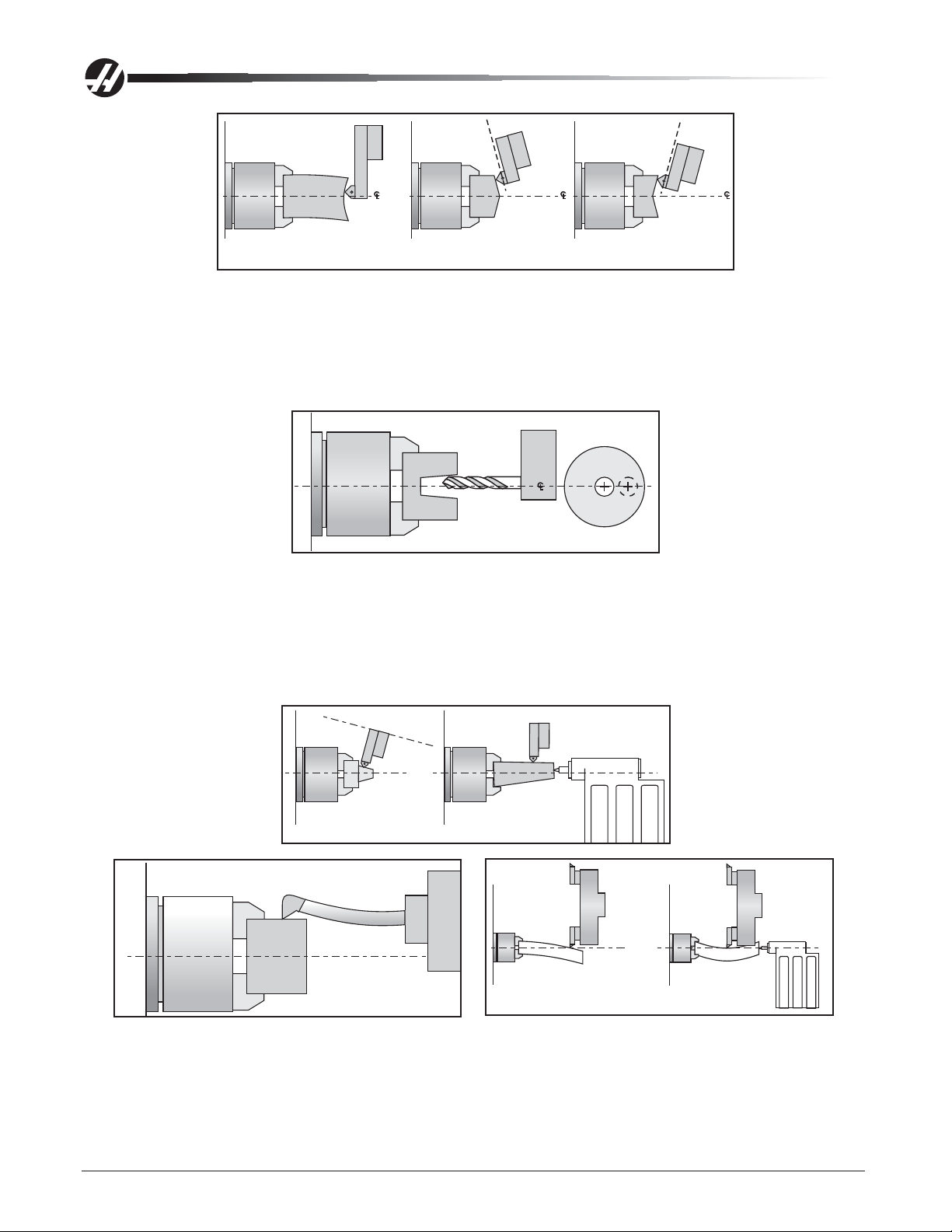
Diameters are out of round
• Check that tooling and machining practices are correct. Bores will be out of round due to tool deflection much
more frequently than due to spindle bearing problems.
Drill
Diameters are incorrect in X-axis
• Ensure the tool probe is set up correctly (settings, etc.).
• Ensure tool offsets are correct. Note that the coordinate system (FANUC, YASNAC, HAAS) must be
selected before setting tools.
• Ensure Parameter 254, Spindle Center, is set correctly.
• Check for thermal growth of the X-axis ballscrew (see “Thermal Growth” section).
Center holes are malformed
• Ensure tooling is tight.
• Ensure Parameter 254, Spindle Center, is set correctly.
• Check spindle to turret pocket alignment. It may be out of alignment due to a crash or misadjustment.
• Check for thermal growth of the X-axis ballscrew (see “Thermal Growth” section).
Part faces are conical
• Wedge may be out of alignment due to a crash.
• Check tooling setup. Turning long, unsupported parts may cause conical part faces.
• Check for thermal growth of the ballscrews (see Thermal Growth” section).
96-0283 rev A June 2006
Mechanical Service
3
Page 5
C
L
C
L
C
L
Part/Tooling Problem Geometry Problem
Bores are tapered
• Check that tooling and machining practices are correct. Bores will be tapered if the tooling is inappropriate,
the speeds and feeds are incorrect, or coolant is not getting to the cutting tool.
• Although it is rare, the spindle may be out of alignment due to a crash.
• Check that the turret face is parallel with X-axis.
C
L
Outside diameter (O.D.) is tapered
• Check tooling setup. Turning long, unsupported parts can cause a tapered O.D.
• Check tailstock setup. Excessive hold pressure on the tailstock can distort parts.
• Spindle to Z-axis may be out of alignment (not parallel).
• Program around it. Reduce depth of final rough cut and finish pass to reduce part deflection.
C
L
Poor Geometry
C
L
C
L
C
L
Poor Technique
Material left after facing a part
• Ensure tooling is correct.
• Ensure turret is aligned to X-axis travel.
C
L
4
Mechanical Service
96-0283 rev A June 2006
Page 6
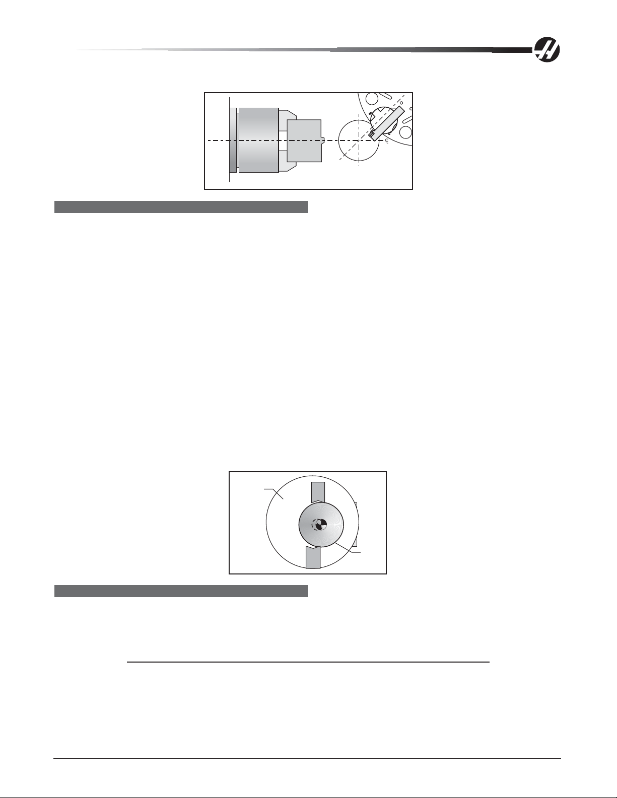
• Ensure Parameter 254, Spindle Center, is set correctly.
Material LeftAfter Facing Part
FINISH
Machining yields a poor finish
• Check for backlash ("Ball Screw Removal and Installation" section).
• Check the condition of the tooling and the spindle.
Vertical & Horizontal Machines
• Check for gearbox vibration.
• Check for spindle failure.
• Check the condition of the axis/servo motors.
• Check that the machine is level (see the Installation section of the Reference manual).
Lathes
• Check turret alignment.
• Ensure turret is clamped.
• Ensure tooling is tight.
• Check tooling for chatter or lack of rigidity.
• Check the balance of the chuck, part, and fixture.
Chuck
Part
THERMAL GROWTH
A possible source of accuracy and positioning errors is thermal growth of ballscrews. As the machine warms
up, ballscrews expand in all linear axes, causing accuracy and positioning errors (or inaccurate boring depths
for vertical and horizontal machines). This is especially critical in jobs that require high accuracy , machining
multiple parts in one setup, or machining one part with multiple setups.
NOTE: On machines with linear scales, thermal growth will not affect machine
positioning or accuracy. However, it is recommended that the machine be
warmed up before cutting parts. The ballscrew always expands away from the
motor end. Thermal growth in a lathe ballscrew will be more noticeable in the
X-axis, since errors will be doubled when cutting a diameter.
96-0283 rev A June 2006
Mechanical Service
5
Page 7

Verify Thermal Growth
There are a number of ways to verify the problem. The following procedure will verify thermal growth of the X-
axis (reverse-anchored for lathes) ballscrew in a machine that has not been warmed up:
1. Home the machine. In MDI mode, press Posit and Page Down to the Oper page.
2. Jog to an offset location on the table (example: X-15.0" Y-8.0" for vert & horiz). Select the X-axis and press
the Origin key to zero it. Select the Y-axis for mills and zero it.
3. Press the Ofset key, then scroll down to G110 (or any unused offset). Cursor to X and press Part Zero Set
once to set X0, then press again to set Y0. Press Z Face Meas once for a lathe.
4. Enter the following program. It will start at the new zero position, rapid 10 inches in the X direction, feed the
final .25 inches at 10 inches/min., and then repeat the X movement.
G00 G110 X0 Y0;
X10.0;
G01 X10.25 F10. ;
M99;
5. In order to set up the indicator, run the program in Single Block mode, and stop it when X is at 10.25" (or
end of its set travel for Lathes). Set the magnetic base on the table, with the indicator tip touching the
spindle housing in the X-axis for vert & horiz, or for lathes, set it on the spindle retainer ring or other rigid
surface, with the indicator tip touching the turret in the X-axis, and zero it.
6. Exit Single Block mode, and run the program for a few minutes. Enter Single Block mode again, stop the
program when X is at 10.25" for vert & horiz or at the beginning of its travel for lathes, and take a final
reading on the indicator. A difference in the X position indicates a thermal growth problem.
NOTE: Ensure indicator setup is correct as described in "Accuracy" section. Setup
errors are commonly mistaken for thermal growth.
7. A similar program can be written to test for thermal growth in the Y- and Z-axes, if necessary.
Solutions
Since there are many variables that affect thermal growth, such as the ambient temperature of the shop and
program feed rates, it is difficult to give one solution for all problems.
Thermal growth problems can generally be eliminated by running a warm-up program for approximately 20
minutes before machining parts. The most effective warm-up is to run the current program, at an offset Z
position before the part for lathes, or above the part or table, with the spindle "cutting air" for vert & horiz. This
allows ball screws to warm up to the correct temperature and stabilize. Once at temperature, ball screws won't
expand any further , unless allowed to cool down. A warm-up program should be run after each time the machine is left idle.
Compensation for Thermal Growth
During normal operation, small inaccuracies in the work pieces may develop due to thermal expansion of the
ball screws. Ball screws are made of steel which expands at the rate of 1 1 millionths of an inch per degree C.
The Haas control contains built-in features to electronically correct for ball screw growth. This compensation
works by estimating the heating of the screw based on the amount of travel over the length of the screw and is
measured from the motor. Adjustment s can be made to the settings as needed. The user can fine-tune this
compensation up to plus or minus 30% with the use of settings 158, 159 and 160. If the part size is too big,
decrease the amount of compensation for the appropriate axis. For example, increasing the value in Setting
158, “X Screw Thermal Comp%”, can increase the amount of thermal compensation.
6
Mechanical Service
96-0283 rev A June 2006
Page 8

WAY COVERS/HEAD COVERS
Recommended T orque V alues for Machine Fasteners - The following chart should be used as a reference
guide when replacing way covers/head covers for torquing machine fasteners where specified.
DIAMETER TORQUE
8-32 30 in-lb
1/4 - 20 15 ft-lb
5/16 - 18 30 ft-lb
3/8 - 16 50 ft-lb
M10 - 100 50 ft-lb
M12 - 65 100 ft-lb
1/2 - 13 80 ft-lb
3/4 - 10 275 ft-lb
1 - 8 450 ft-lb
X-AXIS WAY COVER REMOVAL (HORIZ)
Left/Right Way Cover Removal
1. Jog the X-axis to the center of travel and Power Off the machine.
2. Remove the SHCS that fasten the way covers to the table and remove the SHCS that fasten the way
covers to the outside casting.
Y-AXIS WAY COVER REMOVAL (HORIZ)
Removal - Upper
1. Jog the X-axis to the center of travel and the Y-axis all the way down.
2. Power Off the machine.
3. Remove the BHCS that fasten the way cover to the spindle head and the vertical guides to the column.
4. Remove the top way cover.
Install the way cover in the reverse order above; however, make sure that all necessary gaskets and sealants
are replaced and repaired as necessary .
Removal - Lower
1. Jog the X-axis to the center of travel and the Y-axis all the way up.
2. Power Off the machine.
3. Remove the three (3) BHCS that fasten the way cover to the spindle head.
4. Remove the seven (7) BHCS on each side that fasten the vertical guides to the column.
5. Remove the lower way cover .
Install way covers in the reverse order above; however , make sure that all necessary gaskets and sealants are
replaced and repaired as necessary .
Z-AXIS WAY COVER (HORIZ)
Right Way Cover - Removal
1. Jog the Z-axis (receiver) all the way in the +Z direction (away from the spindle).
2. Power Off the machine.
3. Remove the 14 BHCS that fasten the front of the way cover to the receiver.
96-0283 rev A June 2006
Mechanical Service
7
Page 9
4. Remove the 14 BHCS that fasten the rear of the way cover to the column.
5. Remove the way cover .
Right Way Cover - Installation
1. Power On the machine.
2. Replace the way cover . The end with the smallest section goes toward the receiver .
3. Fasten the column end using fourteen (14) BHCS.
4. Fasten the receiver end using fourteen (14) BHCS.
Left Way Cover - Removal
1. Jog the Z-axis (receiver) all the way in the -Z direction (toward the spindle).
2. Rotate the H-frame 45° counterclockwise.
3. Remove the thirteen (13) BHCS that fasten the rear way cover to the receiver assembly.
4. Remove the rear way cover through the door.
Install way covers in the reverse order above; however , make sure that all necessary gaskets and sealants are
replaced and repaired as necessary .
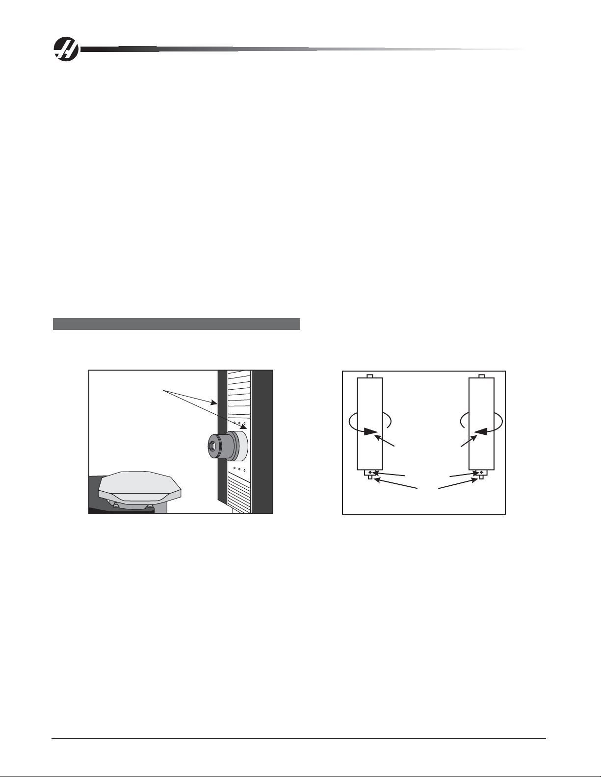
EC-300 X-AXIS WAY COVER ADJUSTMENT
The front of the column on either side of the spindle is covered by heavy shades kept taut by spring loaded
canisters. If the shades should need adjusting, refer to the following procedure.
Shades
Shade Rotation
Set Screw
Flat
Left When
Facing Machine
Right When
Facing Machine
1. Clamp the shaft at the flat with clamping pliers or other such clamping device to hold the shaft when
adjusting of the spring tension.
2. Loosen the set screw so that the spring tension may be adjusted.
3. Rotate the shaft one complete revolution against the force of the spring (counterclockwise for the left
canister and clockwise for the right canister). Retighten the set screw.
4. Check the tension of the shade. Repeat this process as needed for proper tension one revolution at a time.
Do not overtighten the spring.
8
Mechanical Service
96-0283 rev A June 2006
Page 10
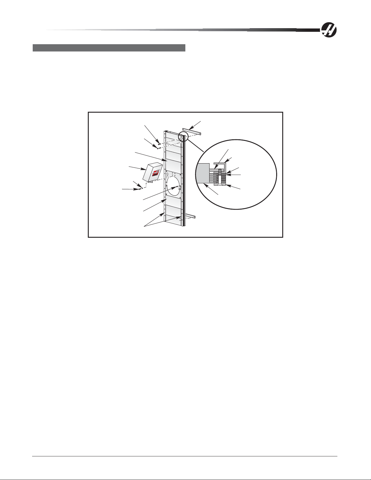
EC-300 Y-AXIS WAY COVER ADJUSTMENT
Upper Way Cover - Removal
1. Handle jog the X-axis to center of travel. Handle jog the Y-axis down fully.
2. Power Off the machine.
3. Remove the twenty six (26) FHCS that attach the vertical guides to the way cover.
4. Remove the six BHCS that the attach the upper way cover to the spindle head and the lower way cover.
20X 1/4-20 UNC
x 1-1/4 SS FHCS
6X 1/4-20 UNC
x 2-1/2 SS FHCS
Upper Y-Axis
Waycovers
P-Cool
(Optional)
4X Lockwasher
4X BHCS
6X BHCS
Lower Y-Axis
Waycovers
Waycover Guide
Rails
2X Holding Bar
Holding Bar
2X Guide Rail
6X Spacer
5X Guide
Bar
Front Bar
Y-Axis
Waycovers
Upper Way Cover - Installation
1. Install the four SHCS at the top of the way cover. Slide it up and down to ensure it moves freely.
2. Slide the way cover down until the bottom flange goes under the spindle head cover and fasten it with four
BHCS.
3. Fasten the left and right vertical guides using FHCS.
Lower Y-Axis Way Cover - Removal
1. Handle jog the X-axis to center of travel. Handle jog the Y-axis up fully.
2. Power Off the machine.
3. Remove the SHCS that attach the left and right vertical guides and remove.
4. Remove the four FHCS that attach the top of the lower Y-axis way cover to the spindle head casting.
Collapse the way cover down fully .
5. Remove the way cover from the bottom.
Lower Y -Axis W ay Cover - Inst allation
1. Install the four SHCS at the bottom of the way cover, and tighten evenly.
2. Slide the bottom of the way cover up and down to ensure it moves freely.
3. Slide the top flange of the waycover under the spindle head cover plate and fasten it to the spindle head
cover and upper waycover using four BHCS.
4. Replace the left and right vertical guides using BHCS.
96-0283 rev A June 2006
Mechanical Service
9
Page 11
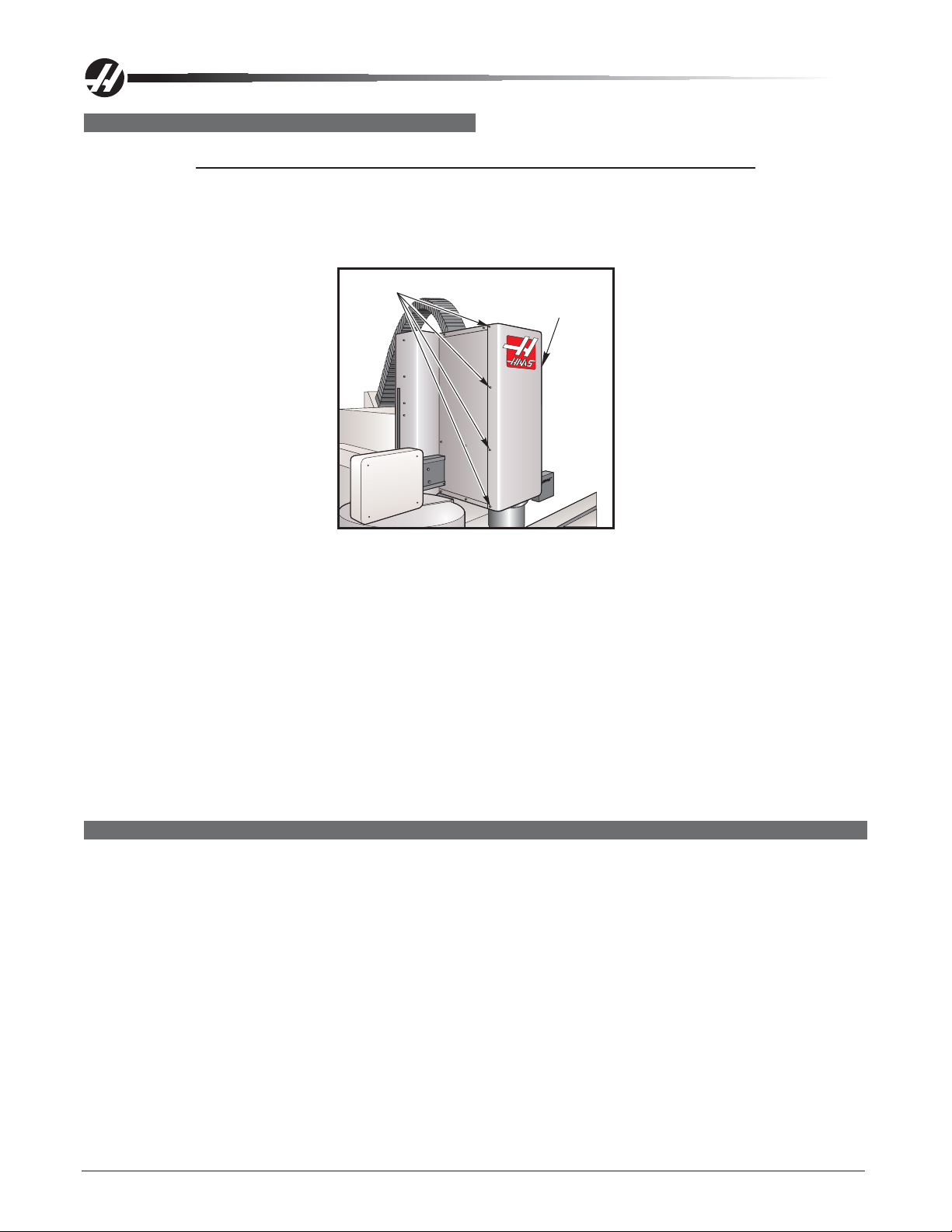
HEAD COVERS REMOVAL/INSTALLATION (VERT)
Removal
NOTE: This procedure is for the VF-3/4. However, the procedure varies only slightly
for other models.
50 T aper machines: Before removing the head cover , remove the fan assembly and disconnect the tool
release and fan electrical connectors.
10-32 x 3/8" SHCS
VF-3/4 Head Covers
Remove side
covers from
top side
1. Zero return (Zero Ret) all axes, then Handle Jog to center X- and Y-axes under spindle. Protect table
surface with a piece of cardboard.
2. Remove the top and rear covers.
3. Pull front cover from the bottom until you can disconnect the tool release cable (quick disconnect), then
remove cover. Remove the side covers. Jog Z-axis as necessary to make screw removal easier.
Installation
1. Protect table surface with a piece of cardboard. Replace each side cover from the top. Jog Z-axis as
necessary to make access to screws easier.
2. Reconnect tool release cable, if equipped, then replace front cover from the bottom. Replace rear cover and
top cover.
TOOL RELEASE PISTON (TRP) ASSEMBLY
Please read this section in its entirety before attempting to replace the tool release piston
assembly.
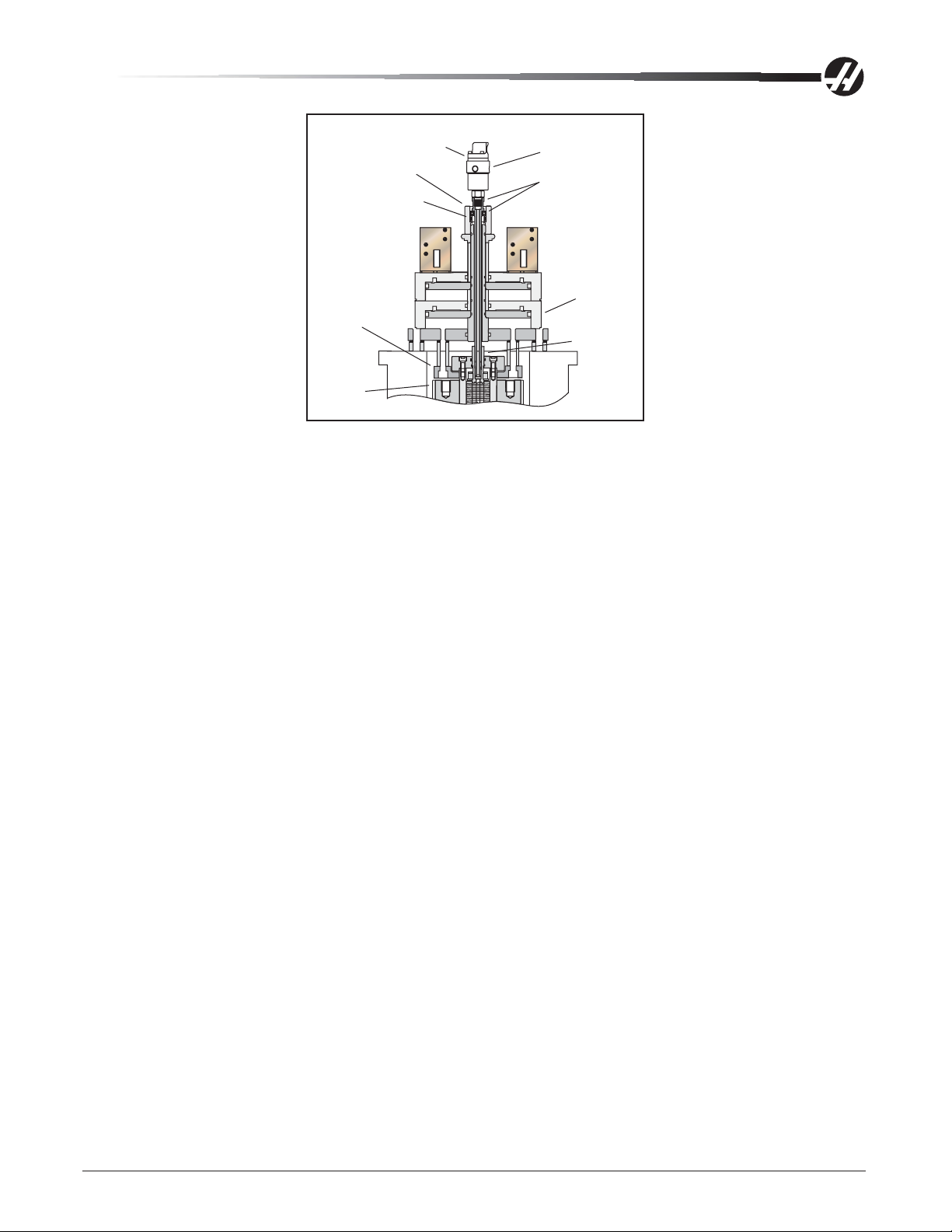
Overview
The tool release piston is actuated by air. It forces the tool draw bar down against the spring st ack, releasing
the old tool and permitting the new tool to be inserted. Normally the piston is in the upper, retracted position.
During a tool change cycle the piston is forced down by air pressure, pushing the draw bar down until the pull
stud on the top of the tool is released.
As the piston finishes its downward stroke a hole in the side of the tool release shaft comes clear of the
cylinder housing and is exposed to the compressed air within the cylinder. The air flows down through the shaft
to the tool release nut at the lower end of the shaft. This nut presses on the end of the tool draw bar and the air
flows through a central hole drilled through both the tool release nut and the tool draw bar to blow any chips out
of the tapered area of the spindle shaft.
10
Mechanical Service
96-0283 rev A June 2006
Page 12

The spring retainer captures the compression spring that returns the tool change piston and shaft to the normal
position when the air is released from the cylinder. The upper and lower limit switches are actuated by the
spring retainer . The position of these switches is monitored by the computer control system during a tool
change cycle.
There are different tool release pistons for 40 and 50 taper spindles. In addition The tool change pistons have
different subassemblies that will need to be adjusted, or may need replacing. The section(s) that follow the
installation instructions must be completed as well or serious damage to the machine could result.
T ool Clamp/Unclamp
The tool holder drawbar is held clamped by spring pressure. Air pressure is used to release the tool clamp.
When the tool is unclamped, air is directed down the center of the spindle to clear the taper of water , oil, or
chips. Tool unclamp can be commanded from a program (but this is quite dangerous), from the keyboard, and
from the button on the side of the spindle head. The two manual buttons only operate in MDI or Jog modes.
T ool Clamp/Unclamp Air Solenoids
A single solenoid controls the air pressure to release the tool clamp. This corresponds to relay K15. When the
relay is activated, 1 15V AC is applied to the solenoid. This applies air pressure to release the tool. Relay K15
is on the I/O PCB. Circuit breaker CB4 will interrupt power to this solenoid.
Tool Clamp/Unclamp Sense Switches
There are two switches located on the tool release piston assembly that are used to sense the position of the
tool clamping mechanism. They are both normally closed, but one open once clamped and the other when
unclamped. When both switches are closed, it indicates that the draw bar is between positions.
A tool change operation will wait until the unclamped switch is sensed before the Z-axis pulls up from the tool.
This prevents any possibility of breaking the tool changer or its support mounts. The diagnostic display can be
used to display the status of the relay outputs and the switch inputs. The Precharge and TSC system applies
low air pressure and releases the clamped switch.
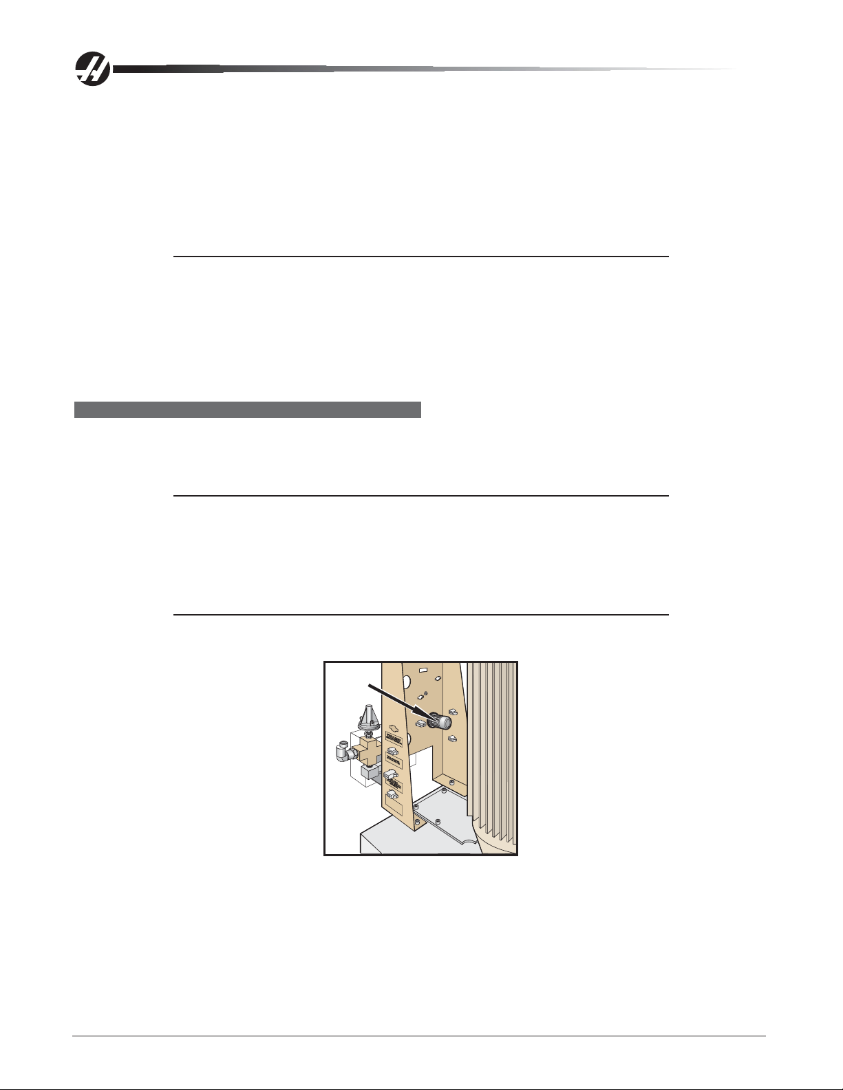
Remote Tool Unclamp Switch
The Remote Tool Unclamp switch is mounted on the side of the cover to the spindle head. It operates the same
as the button on the keyboard. It must be held for ½ second before the tool will be released and the tool will
remain released for ½ second after the button is released. While the tool is unclamped, air is forced down the
spindle to clear chips, oil, or coolant from the tool holder .
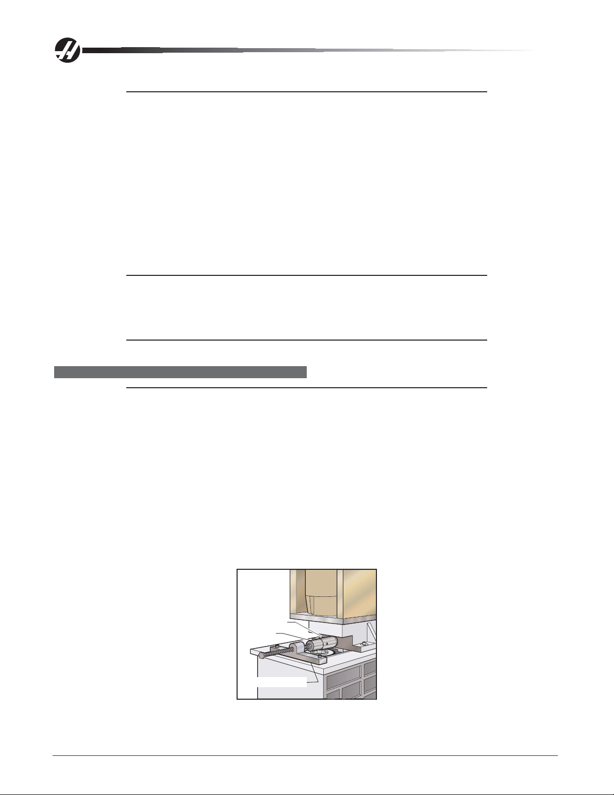
SPINDLE TRP REMOVAL
1. For TSC equipped machines, place a tool holder in the spindle.
2. Remove cover panels from headstock area in accordance with "Head Covers Removal and Installation".
3. For 50 Taper TSC equipped machines the coolant union and extension tube must be removed before
proceeding. They both have left handed threads.
CAUTION: Do not remove pipe connectors from the coolant union! Remov-
ing any pipe connector from the union will void your warranty on
the union. Use wrenches only on the SAE hose connector and
the bottom nut of the Coolant Union. See arrows below:
96-0283 rev A June 2006
Mechanical Service
11
Page 13
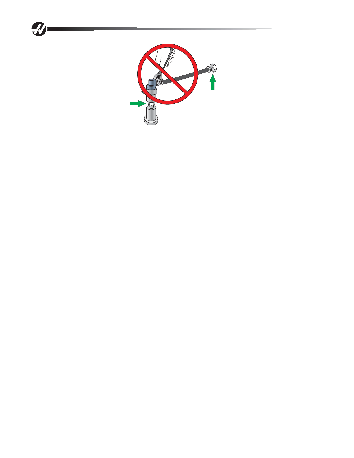
SAE Hose Connector
Left Hand Threads
a. Loosen the SAE hose connector at the check valve assembly with a wrench (right arrow in
diagram). Do not use a wrench on the pipe connector attached to the coolant union; the union will
be damaged and the warranty voided.
b. Carefully cut off the clear plastic drain hose at the side of the coolant union. It is safest to use
scissors or snips. Cut it close to the connector , since the hose will be re-used on the replacement
union. Do not cut the black coolant hose. (Note that if you are not replacing the union, leave the
drain hose attached to the union.)
c. Remove the coolant union from the extension tube (bottom arrow in diagram) using two
wrenches (7/8 and 15/16). This is a left-hand thread.
d. Return the coolant union with all pipe thread connectors and black coolant hose intact to Haas
Automation for warranty. Removal of any of the pipe connectors from the union will void any
claims for warranty.
4. Disconnect the air line at the lube/air panel.
5. Disconnect the clamp/unclamp cables (quick disconnect) and the assembly's solenoid wiring located on
the solenoid bracket.
6. a. 40 Taper - Remove the tool release air hose and precharge hose at the fitting shown in the following
figure. If machine is equipped with TSC, also remove the coolant hose.
b. 50 T aper - Remove the three tool release air hoses.
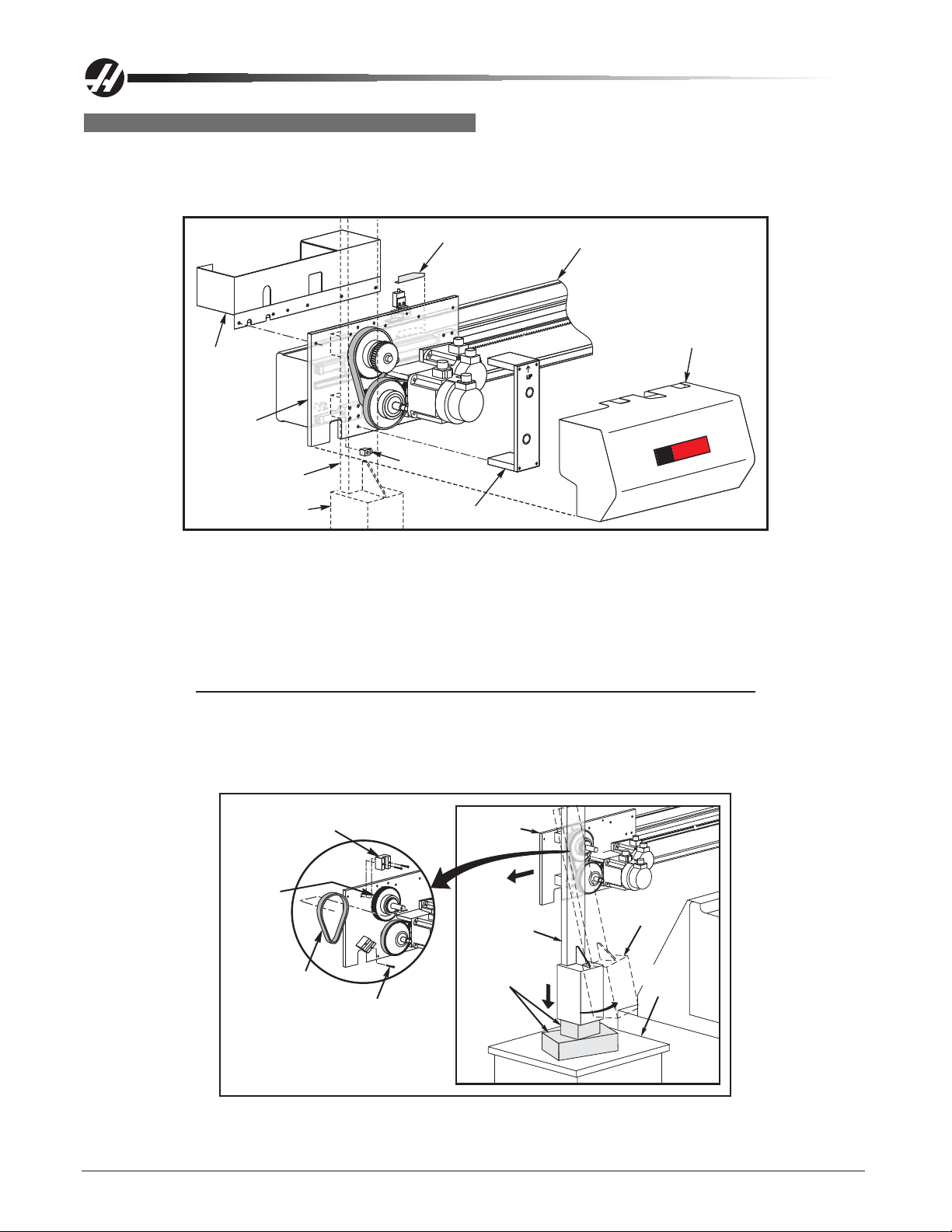
7. Use a strap and overhead lifting device to hold the TRP in position. Remove the four shoulder screws
holding the tool release piston assembly to the head casting. Keep all washers and shims.
12
Mechanical Service
96-0283 rev A June 2006
Page 14
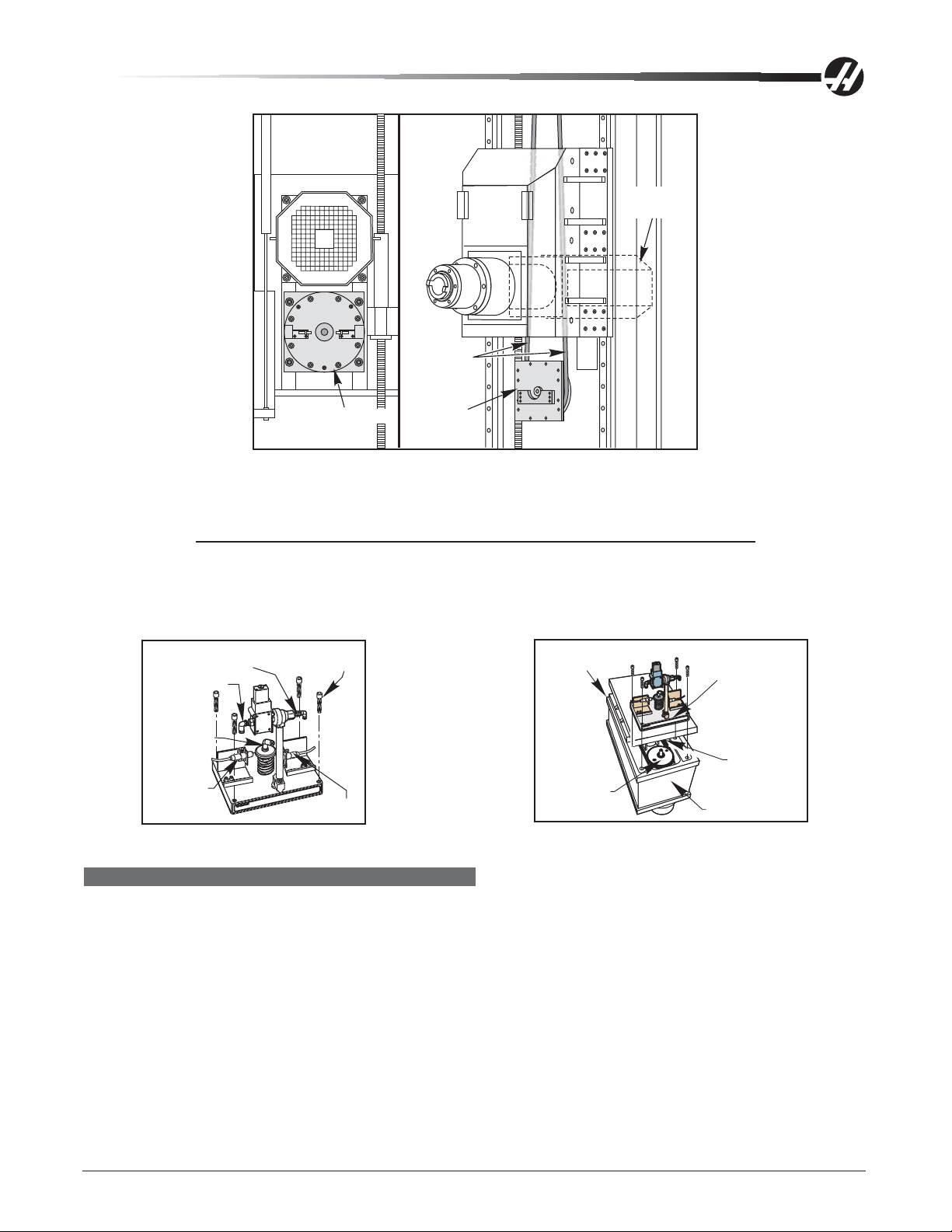
Lifting
Strap
Motor and
Transmission
TRP in Position
TRP
Rear View
TRP Shown in Position and as it is Lowered
8. Remove entire tool release piston assembly, by sliding it forward then lifting it upward. The assembly is
heavy so use great care when removing it.
NOTE: Steps 9 and 10 apply only to machines with TSC.
9. Remove the drain and purge lines from the seal housing.
10. Remove the seal housing from the TRP.
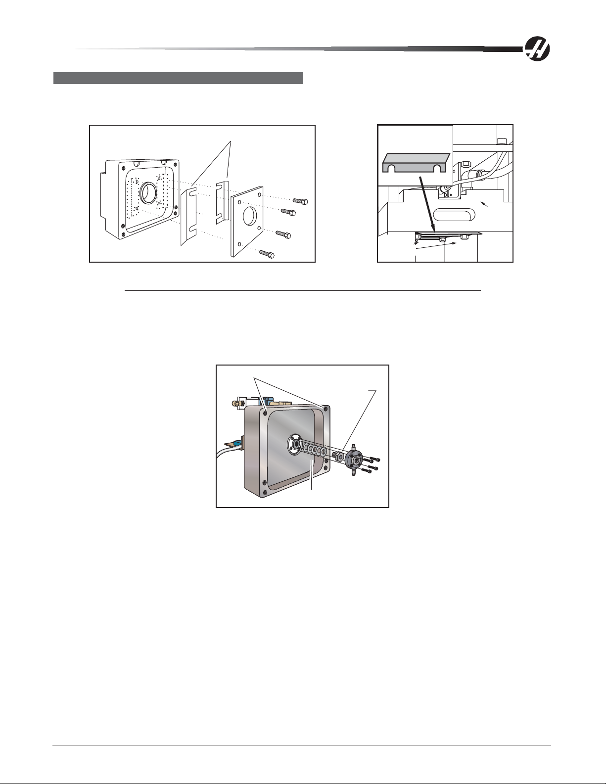
1/4" Air Hose
Fitting
3/8" Air Hose
Fitting
TSC Fitting
(Optional)
Clamp
switch
Tool Release Piston with Optional TSC Fitting Mounting Location for Tool Release Piston Assembly
3/8" - 16 X
1 3/4" SHCS
Unclamp
switch
Transmission
(Optional)
Spindle
Pulley
Tool Release
Piston Assembly
CAUTION
Drive Belt
Head Casting
SPINDLE TRP INSTALLATION
The following sections must be completed after installation:
40 T aper
• Set pre-charge
• Adjust the tool clamp/unclamp switches
• Set the draw bar height
50 T aper
• Tool push out adjustment
• Setting TRP switches
• Extension tube Installation (TSC)
1. 40 T aper - Ensure drive belt has been properly replaced as described in "Belt Replacement and
T ensioning" section.
96-0283 rev A June 2006
Mechanical Service
13
Page 15
2. 40 Taper - Verify spindle sweep adjustment is correct (as shown in "Draw Bar Replacement" section)
before proceeding. If not correct, re-shim as necessary .
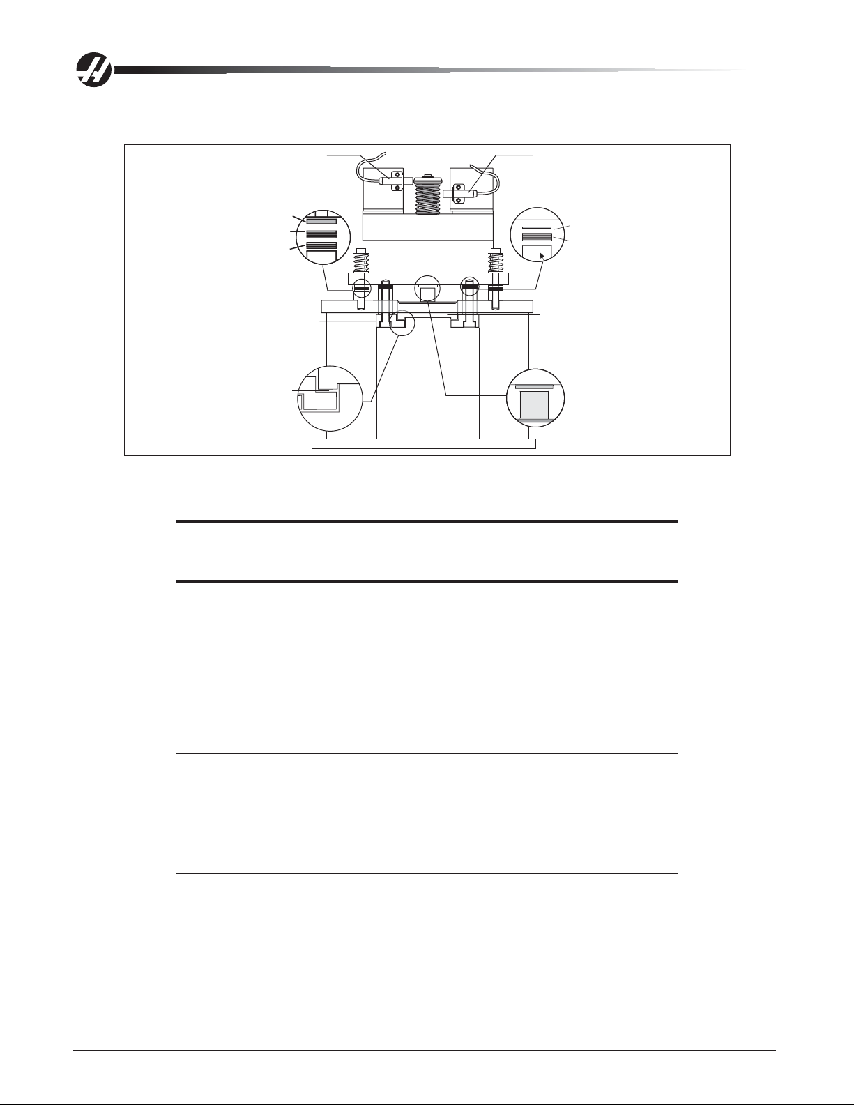
Tool Clamped Switch
TRP Shims
(1 ea.) 0.093 Nylon Washer
(2 ea.) 0.010 Shim Washer
(3 ea.) 0.015 Shim Washer
TRP Fork
Fork Gap
Tool Unclamped Switch
Fork Shims
Spindle Endcap
Shim and Spacer Location Diagram
1. Place the TRP on the machine. The TRP will rest on the spindle lift fork.
CAUTION! Be careful of the spindle lift fork. Place the assembly toward the
front of the machine before lowering it. The assembly is heavy so
use great care when replacing it.
(1ea.) 0.010 Shim Washer
(7ea.) 0.018 Shim Washer
Drawbar Gap
2. Install the 4 bolts, with the shim stock and spacers under the TRP.
Part No. Description 30-0013A (New) 30-0013 (Old Style)
Fork: (45-0014) 0.010 Shim Washer 1 ea. None
(45-0015) 0.018 Shim Washer 7 ea. 5 ea.
TRP: (45-0019) 0.093 Nylon Washer 1 ea. 1 ea.
Spacers: (45-0017) 0.010 Shim Washer 2 ea. 2 ea.
(45-0018) 0.015 Shim Washer 3 ea. 2 ea.
NOTE: TRP Spacers: the nylon washer goes on top of the shims.
3. Reinstall tool release piston assembly loosely if the machine is equipped with TSC. Otherwise tighten the
four mounting bolts securely .
4. 50 Taper - If the machine is equipped with TSC, re-install the extension tube and rotating union in the
following manner. Otherwise, skip this step.
NOTE: If the spindle, draw bar or extension tube has been replaced, the extension
tube runout must be adjusted.
14
Mechanical Service
96-0283 rev A June 2006
Page 16
Measure Runout Of
Rotating Union Here
Bearing Holder
Wave Spring
TRP Fork
Spindle
Pulley
Rotating Union
Extension Tube
Assembly
50 Taper
TRP
Draw Bar
a) Place a tool holder in the spindle.
b) Insert a 5/8 Allen wrench into the lower end of the piston shaft. Loosen the 1/4-20 screw in the
clamp collar on top of the piston shaft. Insert a large flat blade screwdriver into the slot in the
clamp collar, and twist the collar of f.
c) Screw the bearing holder (20-7655) onto the piston shaft. Tighten using a large wrench or pliers.
d) Wipe clean the hole in the end of the draw bar.
e) Replace the tool release piston.
f) Apply a light layer of molybdenum grease to the inside of the bearing holder . Insert the wave
spring (59-0176) into the bearing holder.
g) Lightly grease the o-ring on the end of the extension tube assy (30-1242). Apply blue Loctite to
the thread on the end. Insert the extension tube down into the draw bar. Tighten by hand as far as
possible (it has left hand threads).
h) Block spindle rotation with a bolt, bar or socket inserted into one of the pulley holes. It will stop
against the TRP fork.
i) Tighten the extension tube to 15-20 f t-lb. Remove the bolt from the spindle pulley .
j) Install the rotating union. Lightly grease the o-ring. Do not put Loctite on the threads.
1) Thread the coolant union onto the end of the extension tube (it has left hand threads).
Do not use Loctite. Tighten the threads snugly using two wrenches.
2) Attach the clear plastic drain hose to the barb connector on the side of the union. Use a
hose clamp if one is available. The hose must travel downward (below the union) to drain
off collected coolant. The union will be damaged if coolant collects inside the union.
3) Thread the black coolant hose onto the connector on the check valve assembly . T ighten
with a wrench. Do not over-tighten!
k) Measure the runout at the top of the rotating union with a dial indicator . Runout should not
exceed .006"
l) Check the tool clamp and unclamp switches. They should not have moved.
m) Test run the TSC system to check for leaks before putting the head covers back on.
96-0283 rev A June 2006
Mechanical Service
15
Page 17
5. Reconnect the air hoses at the applicable fittings on the tool release piston assembly.
6. Reconnect the clamp/unclamp cables and solenoid wire to the sides of the solenoid bracket.
7. 50 Taper - Set the main air regulator to 85 psi. Tool push out and TRP switch adjustments must be
completed.
Steps 8-10 only apply to 40 Taper machines with TSC
8. Connect the 5/32" drain line and 5/32" purge line to the seal housing and install the seal housing on the
TRP (use Loctite on the screws). The drain line connector should point toward the rear of the machine.
NOTE: The drain line must run straight through the cable clamp guide on the
transmission, and must not interfere with the pulley or belts.
9. Apply precharge pressure several times to allow the seal to center it self with the draw bar . While holding
down precharge, tighten the bolts.
10. Install the coolant hose. A wrench must be used, tighten snug. Do not overtig hten!!
1 1 . Adjust the clamp/unclamp switches in accordance with the appropriate section.
SETTING PRE-CHARGE
Do not perform on machines equipped with Through the Spindle Coolant (TSC). It will
damage the machine. Refer to the "Precharge Regulator Adjustment" section and perform
those adjustments.
NOTE: Set the air pressure regulator to 30 psi on Super Speed machines with an in-
1. Turn the air pressure regulator to zero (0). The knob must be pulled out to unlock before adjusting. In-Line
drive machines - Disconnect the air hose from the precharge regulator. Inst all a test gauge between the
regulator and the solenoid. Command the precharge (Macro #1 120-1), the pressure should be 30 psi.
NOTE: At "0" pressure on the precharge regulator, the adjustment knob is out as far
line drive, to 4 psi on standard 40 Taper machines, and do not set a precharge
on 50 Taper machines.
as it will turn.
Air Pressure Regulator Adjustment Knob
2. Verify Parameter 149, Precharge Delay, is set to 300.
16
Mechanical Service
SPINDLELOCKED
STATUSSWITCH
WITHOUTGEARBOX
TOOLCLAMPED
STATUSSWITCH
LOW
STATUSSWITCH
JUMPER
GEARBOX
HIGHGEAR
STATUSSWITCH
GEAR
WITHOUT
96-0283 rev A June 2006
Page 18
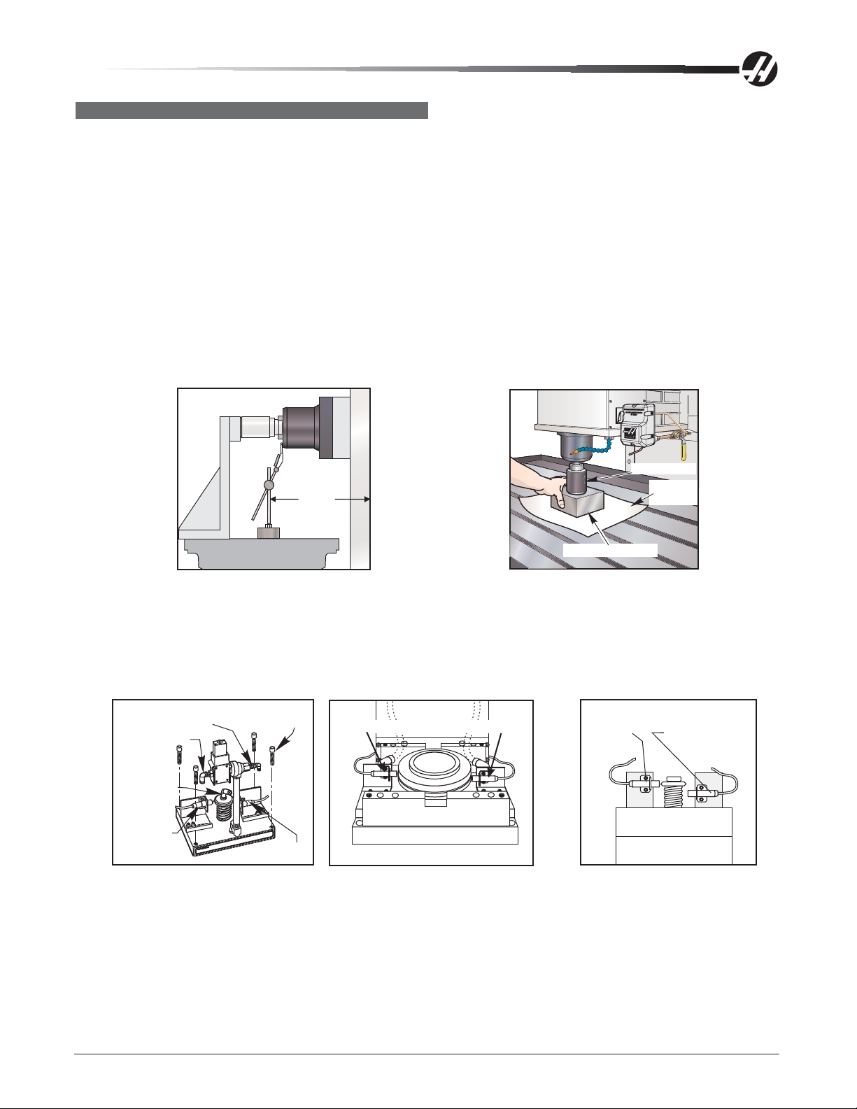
TRP SWITCH ADJUSTMENT
This tool release piston (TRP) switch adjustment procedure applies to 40 Taper, 40 Taper In-Line, and 50 Taper
machines. The switches should indicate that the tool is released from the spindle with the tool 0.060” out of the
taper and that the tool is not released with the tool 0.050” out of the taper .
Lower (Unclamp) Switch
1. Draw bar height must be set properly before adjusting switches. Add or subtract shim washers to the TRP
until proper height is achieved. In-line drive machines must also have the precharge pressure verified.
In-Line drive machines - Disconnect the air hose from the precharge regulator. Install a test gauge
between the regulator and the solenoid. Command the precharge (Macro #1120-1), the precharge pressure
should be 30 psi.
2. Push Param/Dgnos twice to enter the diagnostic mode and confirm DB OPN = 0 and DB CLS = 1.
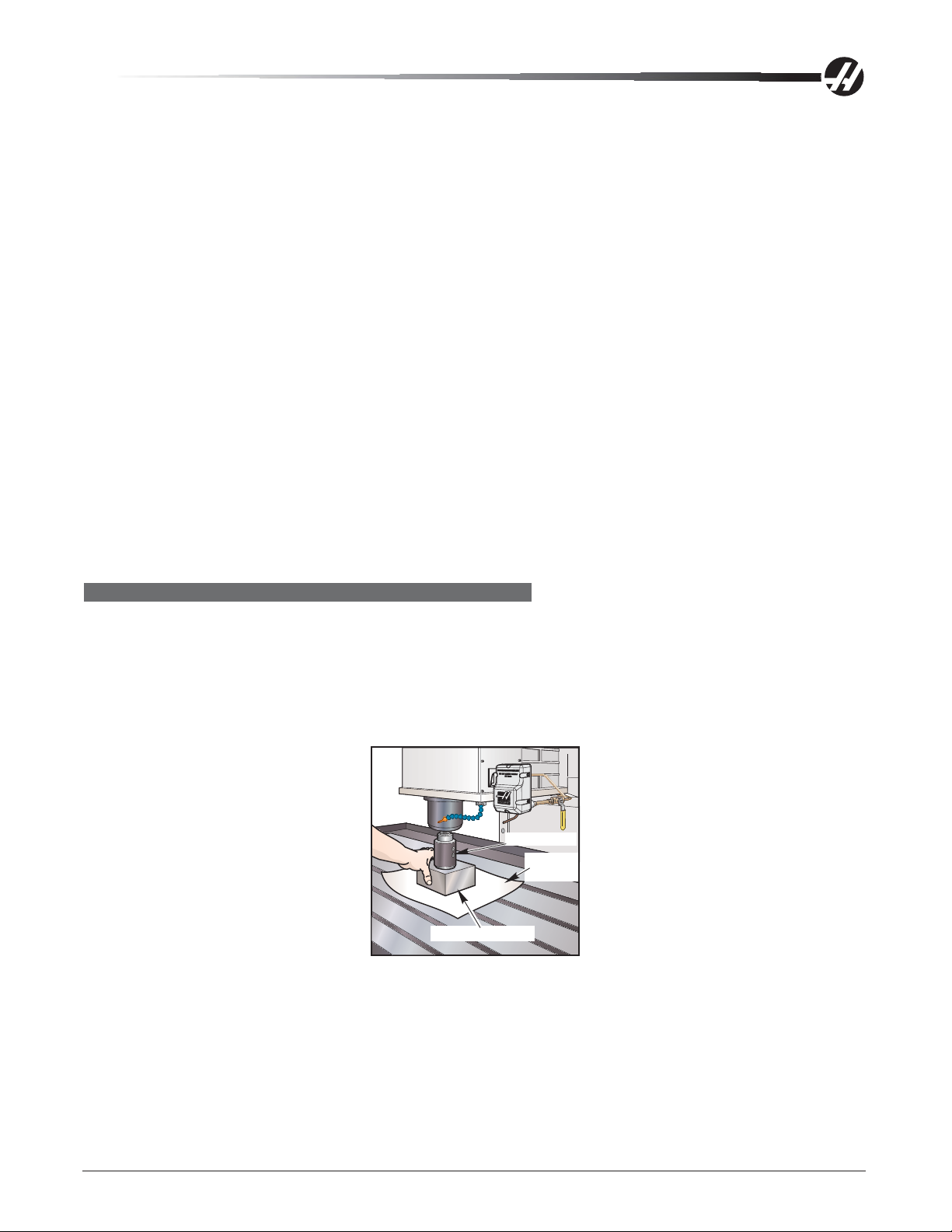
3. Place a tool into the spindle and place a machined aluminum block on the table under the tool holder. Be
sure to place a clean piece of paper under the block to protect the table surface.
Tool Holder
Sheet of
Z-Axis
paper
Aluminum Block
Z-Axis with Angle Block 50 Taper Pushout Adjustment
50 T aper machines - Plug the air blast output at the TRP solenoid so no air is sent to the TRP shaf t.
4. Jog the Z-axis down until the tool holder is about 0.030” above the aluminum block. Switch to .001” incre-
ments. Jog down one increment at a time until the tool holder just presses the block firmly against the
table surface. This is the Zero point. Do not press the Tool Release button, it will cause a Z-axis overload.
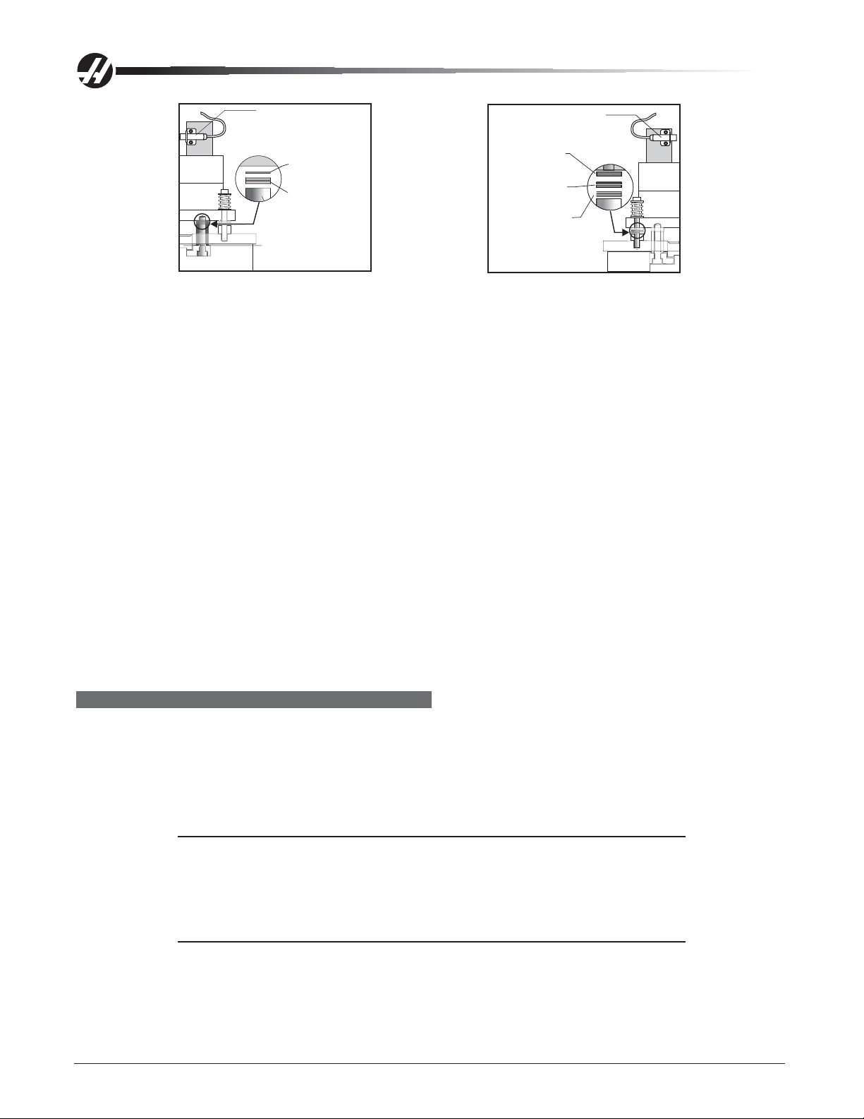
1/4" Air Hose
Fitting
3/8" Air Hose
Fitting
TSC Fitting
(Optional)
Clamp
switch
40 Taper TRP Assembly 40 Taper In-Line Drive TRP Assembly 50 Taper Tool Clamp/Unclamp Switches
3/8" - 16 X
1 3/4" SHCS
Unclamp
switch
Clamp Switch
Unclamp Switch
Tool Clamped
Switch
Tool Unclamped
Switch
5. Change Parameter 76, Low Air Delay, to 45,000 to eliminate a low air pressure alarm.
96-0283 rev A June 2006
Mechanical Service
17
Page 19
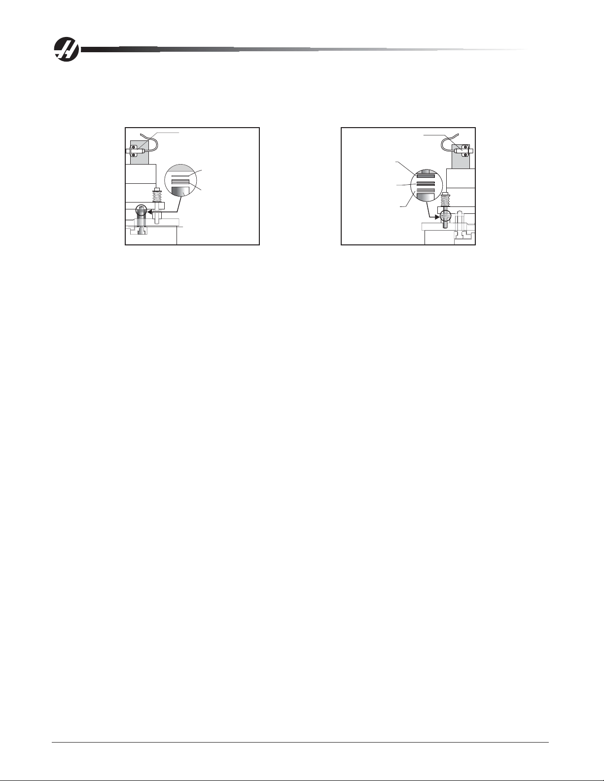
The following notes in Step 6 are for 50 Taper machines only.
6. Jog the Z-axis to 0.060” above where the tool holder was touching the aluminum block and press the Tool
Release button. Add or remove shims from the tool release fork to make adjustments. The shims come in
0.010 and 0.018 thicknesses.
Tool Unclamped
Switch
Fork Shims
(1ea.) 0.010
Shim Washer
(7ea.) 0.018
Shim Washer
Spindle Endcap
50 Taper Fork Shim Location 50 Taper TRP Shim Location
Tool Clamped
Switch
(1 ea.) 0.093
Nylon Washer
(2 ea.) 0.010
Shim Washer
(3 ea.) 0.015
Shim Washer
TRP Shims
• If the block is tight when the button is pressed, shims may have to be added to the tool release
fork. If the block is loose, shims may have to be removed from the tool release fork.
• If the aluminum block is tight at 0.060, release the Tool Release button and jog the Z-axis up
0.001” and press the Tool Release button again. Feel for movement in the aluminum block. Repeat
this until movement is felt. Note the last position where the block was tight. If the position is 0.070”
or more from the Zero point, add shims to the tool release fork.
• If the aluminum block is loose at 0.060, jog the Z-axis downward 0.001” at a time and check for
movement in the aluminum block. If the position where the block becomes tight is 0.050” or less,
remove shims from the tool release fork.
If shims were added to the TRP fork, add half that amount to the TRP spacers supporting the TRP. This will
keep the two clearance gaps between the TRP and the rotating Spindle equal (approximately 0.095” each).
If shims were removed from the TRP fork, remove half that number of shims from the spacers.
Apply red grease to the shoulder bolts used to mount the TRP when shim adjustments are complete.
7. In order to limit the spindle head deflection during this next part of the procedure, the air pressure needs to
be reduced to lower the output force of the TRP. For the Mini-Mill and Toolroom Mill, lower the air pressure
to 75 psi (be sure to back the regulator down past 75 psi, then adjust back up to 75 psi) and proceed to
the next step. For all other 40 Taper mills (including in-line), reduce the air regulator to about 60 psi.
For 50 T aper machines, reduce the air regulator to about 70 psi.
8. Place a 0.0005” test indicator between the table and the bottom of the front face of the spindle head to
measure axial deflection when the tool release piston is energized. Press and hold the Tool Release button
and check that the block is tight and the head deflection is between 0.002” and 0.004” (0.001” and 0.002”
for 50 Taper machines). If the head deflection is too high, reduce the air pressure. If the head deflection is
too low, or there is no deflection, increase the air pressure.
18
Mechanical Service
96-0283 rev A June 2006
Page 20

Z-Axis
T est Indicators
9. Press the Tool Release button and hold it in. Adjust the switch in or out toward the spring retainer until the
switch changes status (DB OPN = 1). The switch should now be indicating that the tool is unclamped and
out of the spindle.
10. Cycle the tool release several times and confirm the switch is tripping. Confirm on the Diagnostics Page
that (DB OPN = 1) and (DB CLS = 0). For a 50 Taper machine, tighten down the screws that secure the
switch bracket to the TRP.
11. Check the adjustment. Jog the Z-axis down until the tool is .050 above the block (0.020” for 50 T aper
machines) and confirm that DB OPN = 0 when the Tool Release button is pressed. The switch must trip
(DB OPN = 1) at 0.060" above the block and not trip (DB OPN = 0) at 0.050" above the block.
12. Re-adjust and repeat steps 4-11 if necessary.
13. Set the pressure regulator back to 85 psi.
14. Set Parameter 76 back to its original setting.
Upper (Clamp) Switch
1. If the machine is equipped with TSC, remove the seal housing before continuing. This step does not apply
to In-line drives with TSC.
2. Remove the tool holder from the spindle.
3. Delete everything in MDI mode and write “#1 120 = 1”.
4. Start with the upper switch all the way in. Place a 0.020” shim between the TRP adjustment bolt and the
draw bar.
Tool Release
Tool Release
Drawbar
Spindle Cartridge
Placement of Shim before Checking Switch Adjustment Placement of Shim (In-Line Drive Motor)
96-0283 rev A June 2006
Piston
Shim
Assembly
Drawbar
Spindle Cartridge
Mechanical Service
Assembly
Piston
Shim
Shim
19
Page 21

In-Line drive machines only - Apply pre-charge.
5. Push the Param/Dgnos button twice to enter the diagnostics mode.
6. Press Cycle Start.
7. If DB CLS = 0 (Tool Unclamp) you are done (do not check with 0.040” shim). If not, adjust the upper switch
out until the switch is just un-tripped (DB CLS = 0) and continue with the next step.
8. This step is not necessary for In-Line Drive machines. Press Reset. Replace the 0.02” shim with a
0.04” shim (checking with the 0.04” shim assures that the switch is not backed off too far. If switch is all
the way in, this check is not needed). Press Cycle Start. See that DB CLS = 1. Readjust and repeat steps
2-8 if necessary.
9. In-Line drive machines only - T ighten the switch mounting bracket and test the adjustment. Apply pre-
charge with a 0.020” shim. Ensure that DB CLS = 0.
CAUTION! Remove the tool holder from the spindle before performing the Clamp
switch adjustment. Failure to remove it could result in damage to the tool
holder, the mill table, or cause severe personal injury.
50 Taper Only
Push the upper switch in slowly toward the spring retainer at the top of the TRP. When the switch LED
changes state, it is indicating that the draw bar is closed. Confirm this on the Diagnostics Page that (DB CLS
= 1). Tighten down the screws that secure the switch bracket to the TRP. Double-Check the switch by turning
on the TRP a few times. DB CLS in the Diagnostics Page should always turn on (1) when the TRP is com-
pletely retracted.
TRP INSTALLATION AND ADJUSTMENT - OM-1A/OM-2A
Upon installation of the TRP, the top of the spindle gear must sit flush with the bottom of the subplate of the
TRP casting. If the TRP subplate casting sit s above the spindle, add .01” shims as necessary. Connect an air
pressure gauge to the TRP Pre-Charge, and adjust the pressure until it reads 6 psi upon tool release. Insert
shoulder bolts and torque to 18 ft-lb.
NOTE: Upon tightening of the fasteners, the TRP must fully return to its original
position.
Draw Bar Height Adjustment
1. Place a machined aluminum block on the table under the tool holder (with no tool in the spindle). Be sure
to place a clean piece of paper under the block to protect the table surface.
2. Jog the Z-axis down until the tool holder is about 0.030” above the aluminum block. Set the clearance from
the tool holder to the block to zero by pressing Tool Release, switching to .001” increments, and jogging
down one increment at a time. Move the Z-axis, then press Tool Release while feeling for movement of the
tool holder (place finger between tool holder and spindle). Repeat process until no movement is felt. This is
the zero point.
3. In .01” increments, handle jog the Z-axis to .100” above the block.
4. Press and hold the Tool Release button. Try to move the block. The block should be tight at .100”, and
loose at .110”. If the block moves at .100”, repeat the process, jogging the Z-axis down one increment at a
time until the block is tight. If the block is tight at .110”, repeat the process, jogging the Z-axis up one
increment at a time until the block is loose.
NOTE: The number of increments jogged up or down is equal to the number of shims
20
to add or remove. If the block was tight at .110”, remove shim washers. If the
block was loose at .100”, add shim washers.
Mechanical Service
96-0283 rev A June 2006
Page 22
Shim Washer Addition/Removal
T o add or subtract shim washers, remove the TRP assembly .
1. Check the condition of the tool release tip and draw bar and replace damaged parts before setting draw bar
height.
2. Remove the tool release bolt.
3. Add or remove the required number of shim washers.
4. Reinstall the tool release bolt.
5. Inst all the TRP assembly and recheck settings. Adjust as required.
Upper (Clamp) Switch
1. Delete everything in MDI mode and write #1 120 = 1.
2. Start with the upper switch all the way in.
3. Place a 0.020” shim between the tool release piston adjustment bolt and draw bar and press Cycle Start.
4. If DB CLS = 0 (tool unclamp), the process is complete. If not, adjust the upper switch out until the switch
untrips (DB CLS = 0), and test the adjustment.
5. Press Reset.
6. Replace the 0.020” shim with a 0.040” shim and press Cycle Start.
7. Verify that DB CLS = 1. Readjust if necessary.
TOOL PUSH OUT ADJUSTMENT
1. Put tool holder in spindle.
2. Plug the spindle taper air blast.
3. Place an angle plate (machined aluminum block - V ert) on machine t able. Place a clean aluminum block
between the angle plate and the tool holder (Horiz), or protect the table by using a clean sheet of paper
under the block (Vert).
Tool Holder
Sheet of
paper
Aluminum Block
Pushout Adjustment (V ert)
4. Jog the Z-axis until the tool holder is about .030” from the aluminum block. Switch the jog increments to
.001” and jog the Z-axis one increment at a time until the tool holder just presses the block firmly against
the angle plate (table surface for V ert). This is the zero point.
96-0283 rev A June 2006
Mechanical Service
21
Page 23
Tool Unclamped
Switch
Fork Shims
(1ea.) 0.010
Shim Washer
(7ea.) 0.018
Shim Washer
Spindle Endcap
Fork Shim Location TRP Shim Location
Tool Clamped
Switch
(1 ea.) 0.093
Nylon Washer
(2 ea.) 0.010
Shim Washer
(3 ea.) 0.015
Shim Washer
TRP Shims
5. The tool push out adjustment is 0.060” +/-0.010”. Add or remove shims from the tool release fork to make
adjustments. The shims come in 0.010” and 0.018” thicknesses. Jog away from the plate (upward for V ert)
0.060. Press and hold the T ool Release button, and feel for movement in the aluminum block.
• If the block is tight when the button is pressed, shims may have to be added to the TRP fork.
• If the block is loose when the button is pressed, shims may have to be removed from the TRP
fork. (This is the opposite of 40 taper adjustment.)
• If the aluminum block is tight at 0.060”, release the button and jog the Z-Axis away from the
block 0.001” and press the T ool Release button again. Feel for movement in the aluminum block.
Repeat this until movement is felt. Note the last position where the block was tight. If the position `
is 0.070” or more, add shims to the TRP fork.
• If the aluminum block is loose at 0.060”, jog the Z-Axis toward the block 0.001 at a time and
check for movement in the aluminum block. If the position where the block becomes tight is 0.050”
or less, remove shims from the TRP fork.
7. If shims were added to the TRP fork, add half that amount to the spacers supporting the TRP. This will
keep the two clearance gaps between the TRP and the rotating spindle equal (approximately 0.095 each).
If shims were removed from the TRP fork, remove half that number of shims from the spacers.
8. Apply red grease to the shoulder bolts used to mount the TRP when shim adjustments are complete. Use
blue Loctite on the threads.
SETTING TRP HEIGHT
1. Press MDI and turn hand wheel to zero (0).
2. Press Handle Jog button and set increments to .01. Jog the Z-axis in the positive (+) direction 0.100".
3. Press and hold the Tool Release button, grasp the block and try to move it. The block should be tight at
.100 and loose at .110. If block moves at .100, jog Z-axis in the negative (-) direction one increment at a
time. Press the Tool Release button and check for movement between increments until block is tight.
NOTE: The increments jogged in the Z negative (-) direction are the amount of shim
washers that must be added to the tool release bolt (or coolant tip for TSC).
Refer to the "TRP Shims" section.
4. If the block is tight at .110, move the Z-axis in the positive (+) direction one increment at a time. Press the
T ool Release button and check movement between increments until block is loose.
22
NOTE: The increments jogged in the Z positive (+) direction are the amount of shim
washers that must be removed ("TRP Shims" section).
Mechanical Service
96-0283 rev A June 2006
Page 24
TRP SHIMS
The draw bar uses a 1-piece shim which can be added or removed without having to remove the TRP assembly .
Once the shims have been adjusted, the TRP is reinstalled and the final torque on the bolts is 35 ft-lb.
Shims
T ool Release Piston Shims
NOTE: Shims may need to be added or removed when spindle cartridge, tool release
piston assembly, or draw bar is replaced. If none have been replaced, skip this
section.
2 Bolts
On Each
Side
Shim
TRP
1. Check the condition of the tool release bolt and the draw bar . Rep air or replace these items before setting
the draw bar height.
Mounting Bolt Locations
Tool Release
Bolt
Shim Washers
TRP Assembly (TSC Shown)
2. Remove tool release bolt. Note that it has a left hand thread. If the machine is equipped with TSC, loosen
the three set screws and remove the TSC coolant tip.
3. Add or subtract required shim washers (see previous section for correct amount to add or remove).
4. Before installing tool release bolt, put a drop of serviceable (blue) Loctite on the threads and install. If
replacing TSC coolant tip, put a drop of Loctite on the threads of the three set screws before installing.
5. Install tool release piston assembly in accordance with the "Spindle TRP Installation" section and recheck
settings. If within specifications, continue; if not, readjust.
In-Line Drive Spindle Draw Bar Height
The draw bar height is set as for the belt driven spindle; however, the shim washers are set up dif ferently . The
draw bar uses a one-piece shim which can be added or removed without having to remove the TRP assembly .
Once the shims have been adjusted, the TRP is re-installed, and the final torque on the bolts is 35 ft-lb.
96-0283 rev A June 2006
Mechanical Service
23
Page 25

TRP DISASSEMBLY
1. Loosen and remove the shaf t clamp. A punch and mallet may be required to break the clamp loose.
2. Remove the switch trip and compression spring.
3. Remove the 50T upper spacer.
4. Push the TRP shaft down.
5. Remove the 8 bolt s holding the TRP assembly together , separate and remove upper half of the housing.
6. Remove the upper TRP piston and remove the lower half of the TRP housing.
7. Remove the TRP lower spacer , the lower TRP 50T piston and the TRP sub plate.
O-ring Replacement
1. Remove and replace the 4 o-rings (57-0027) on the TRP 50T shaft
2. Remove and replace the 2 o-rings (57-0092) on the TRP 50T piston, 1 o-ring per piston.
3. Remove and replace the 3 o-rings (57-0095); 2 in the center of the TRP 50T housing and 1 in the center of
the TRP 50T sub plate.
TRP ASSEMBLY
1. Place the TRP sub plate over the TRP shaft, the lower TRP piston, grooved side up, and the TRP lower
spacer over the TRP shaft.
2. Install the lower TRP housing, the upper TRP piston, grooved side up, and the upper TRP housing over the
TRP shaft.
3. Replace the 8 bolt s holding the TRP assembly together . Pattern torque to 50 f t-lb.
4. Place the TRP upper spacer over the TRP shaft.
5. Push the TRP shaft up from the bottom, using the mallet handle. The shaft will bottom out with approxi-
mately 1/4" of the shaft still showing.
6. Place the switch trip and compression spring over the TRP shaft.
7. Tighten the shaft clamp on the TRP shaft, then the shaft clamp locking bolt.
24
Mechanical Service
96-0283 rev A June 2006
Page 26
BELT REPLACEMENT & TENSIONING
Please read this section in its entirety before attempting to replace the Vertical or ECSeries drive belt.
DRIVE BELT RPLACEMENT (VERT & EC-SERIES)
Removal
NOTE: For easier removal, place transmission in high gear before beginning.
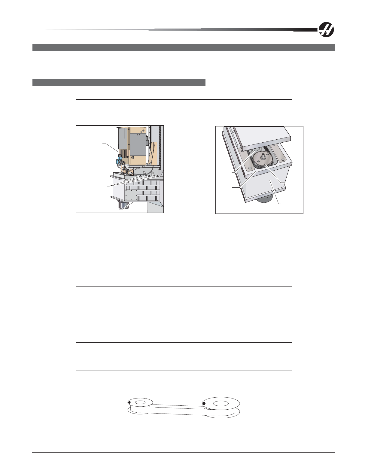
1. Remove cover panels from headstock area in accordance with "Head Covers Removal/Installation".
Transmission
(Optional)
Motor
Shifter
Drive
Belt
Spindle
Pulley
3/8 - 16 x 1"
SHCS
C
A
U
TIO
N
-TOOLCLAMP/UNCLAMP SWITCHESMUSTBEPROPERLY
ADJUSTEDBYTRAINED PERSONNELORSEVEREDAMAGE TOTOOLCHANGER
WILLRESULT.PLEASE CONSULTSERVICEMANUALBEFORE ADJUSTMENT.
Head
Inspection Cover
Casting
Spindle Head Casting Disconnect Points Head Casting Area Showing Belt Location
2. Remove tool release piston assembly in accordance with "Spindle TRP Removal".
3. a. Vert: Remove the six SHCS holding the transmission to the head casting and pull the transmission
forward enough (½" to ¾" max.) to allow the drive belt to be pulled upward over the spindle pulley .
b. Horiz: Remove the four large SHCS that attach the transmission mount plate to the spindle head and
pull the transmission/motor assembly toward the front of the machine slightly to remove the tension on the
drive belts, and remove the drive belts.
NOTE: On direct drive machines, remove the four SHCS holding the mounting plate
to the spindle head casting. Slide the assembly forward enough to allow the
drive belt to be pulled up over the spindle pulley.
4. Remove the inspection cover from the bottom of the spindle head casting and carefully slide the drive belt
between the sump tank and the web in the casting.
5. Pull the belt up over the spindle pulley, push the other end down to clear the shifter, and pull out.
NOTE: Do not bend or kink the belt in any way; damage to the fibers in the belt may
Installation
NOTE: Belt clocking must be correct before placing replacement belt(s) onto the
96-0283 rev A June 2006
result, and the belt will fail soon after installation.
pulley(s). Rotate the pulleys until the alignment dots are in line, but not facing
each other, as shown in the following illustration.
Belt Clocking
Mechanical Service
25
Page 27
1. a. Vert: Slide the replacement belt(s) under the sump tank and onto the pulley.
NOTE: Do not wrap the belts over the pulley. The pulley can be rather sharp, and may
cut the belts. Do not bend or kink the belt in any way; damage to the fibers in
the belt may result, causing belt failure.
b. Horiz: Slide on the drive belts.
2. a. Vert: Ensuring the belt is properly seated, push the transmission back, tightening the belt. Pull belt
forward from rear of head casting. Pull belt over spindle pulley .
b.Horiz: Replace the TRP solenoid assembly and TSC valve bracket. Orient the transmission/motor
assembly and replace the transmission mount plate to the spindle head.
3. a. Vert: Tighten the drive belt in accordance with the following section.
b. Horiz: Use a belt tensioning tool to tighten the drive belts. Do not over tighten.
4. Set the spindle orientation (“Spindle Orientation” section).
NOTE: The following step is necessary only if the spindle or transmission was
exchanged prior to belt replacement.
5. Double-check the spindle sweep to assure that nothing has moved during the previous steps. If sweep is
within tolerance, continue; if not, sweep must be readjusted.
NOTE: Drive belt tension must be adjusted after every installation.
DRIVE BELT TENSIONING (VERT & EC-SERIES)
NOTE: The drive belt tension should be adjusted after every service on the transmis-
sion or spindle of the machine. Information placed in parentheses applies to
Direct Drive machines.
1. Turn the machine On. Jog the spindle head down to a level that will allow easy access to the drive belt.
2. Remove the cover panels from the head stock area as shown in "Head Covers Removal/Installation".
3. Remove the tool release piston assembly in accordance with “Spindle TRP Removal”.
4. Loosen the six (four) SHCS holding the transmission (motor mounting plate) to the spindle head casting.
Ensure the transmission (motor) is broken free by moving it slightly by hand.
5. Set the belt tension tool in place. Mount it to the head casting by inserting the two SHCS into the two front
TRP mounting holes. Tighten the SHCS finger tight. Turn the handle until the tool is flat against the trans-
mission casting (motor mounting plate). Ensure the transmission (motor) is straight, and not cocked,
before tensioning belt.
Outer Tube
Plunger
Belt Tension Tool
26
Belt T ension Tool
Mechanical Service
96-0283 rev A June 2006
Page 28

6. Turn the handle until the edge of the tool's plunger and the outer tube are flush, and then 1/2 turn more.
This will set the belt at the proper tension.
NOTE: A belt that is correctly tensioned will whine slightly, and requires approximately
12 hours of break-in time.
7. Check if the belt is too loose or too tight. If the belt is set too tight, the belt will whine excessively when the
assembly is at speed; and if it is set too loose, it will vibrate during accelerations and decelerations.
8. With the tool still in place, tighten the six (four) SHCS holding the transmission (motor mounting plate) to
the spindle head casting.
9. Loosen the two SHCS and remove the belt tension tool.
30K Spindle
There are two types of belts (3 rib and 4 rib) used on the 30K Spindle Drive. To ensure maximum performance,
the spindle drive belt should be checked for proper tension every 6 months or 1000 hours of operation. The
tension is measured using a Gates Sonic Tension Meter, model number 505C or 507C (used for all belt tension
measurements).
The following table displays the proper lbf(pounds force)/Hz tension readings.
Belt New Belt Used Belt
Number of Ribs Minimum Maximum Minimum Maximum
3 Rib 53.7 lb
f
174 Hz 180 Hz 161 Hz 167 Hz
4 Rib 60.8 lb
f
159 Hz 165 Hz 148 Hz 154 Hz
NOTE: Specific settings must be entered into the tension meter to obtain a correct
tension reading, and are listed below. The Gates Sonic Tension Meter is
capable of retaining 10 to 20 separate combinations of settings depending
upon model. Be sure that you are on the correct belt drive storage register
before taking a reading.
57.6 lb
64.8 lb
f
f
46.2 lb
52.0 lb
f
f
50.1 lb
56.4 lb
f
f
Setting for 3 rib belt: Weight 13.1, Width 3, Span 225
Setting for 4 rib belt: Weight 13.1, Width 4, Span 225
SPINDLE BELT TENSIONING (OM-1A/OM-2A)
The spindle belt tension is measured using a Gates Sonic Tension Meter, model number 505C or 507C.
1. Place the Gates Sonic Tension Meter in Setting #1.
2. Place the meter’s sensor within 3/8” of the belt, and pluck the belt like a guitar string, taking care that the
sensor does not touch the belt.
3. Set belt tension for the Office Mill 30,000 RPM spindle at 43# to 47#.
4. Torque spindle motor fasteners to 30 ft-lb.
96-0283 rev A June 2006
Mechanical Service
27
Page 29
APL MOTOR BELT REPLACEMENT
W-Axis Motor Belt Replacement
A lathe’ s W-axis motor belt s control the raising and lowering of the APL arm. The following instructions are to
service the belts in case a belt is in need of replacement. It is recommended to replace both belts at a time.
Cable
Junction
Carriage
Assembly
W-Axis Ram
RotatorAssembly
Home Switch
Trip Bracket
Hard Stop
Bearing Support
Beam
Carriage Cover
AUTOMATIC
PARTSLOADER
APL
Replacing the Belt(s)
1. Jog the APL U-axis as far to the left of the machine as possible and disable the axis by selecting Parameter 354 and changing the bit value from 0 to 1.
2. Remove the hard stop and home switch trip bracket, remove the APL carriage cover, and press E-Stop.
3. Manually push the carriage away from the machine until the two metal linear rail guide pads (held by 2
bolts each) are exposed. The entire arm assembly has to clear the table.
NOTE: Only push as far as needed to be able to access the four bolts on the two guide
rail blocks.
4. Using a sufficient block (which will have to be taller than the parts table) jog the APL down and support the
bottom of the rotating head.
Remove Upper
Guide Rail Block
with two SHCS
Pinion
Gear
Remove
Upper Belt
Remove One SHCS
(Right Side Only
Carriage
Assembly
B-Axis
Ram
Support
Blocks
Rotator
Assembly
Support
Table
28
Mechanical Service
96-0283 rev A June 2006
Page 30
5. Remove the top linear rail guide block (2 bolts) which will drop down to the bottom block. Only remove
the inside bolt on the bottom linear guide block. The remaining bolt (outside) on the bottom guide
block should only be loose.
6. Remove the bearing support bracket and position the ram outwards so that there is sufficient clearance to
remove the pinon gear which will yield access to the rear motor belt.
7. Loosen the W -axis motor support housing so that there is enough slack to position the belt. After the belts
have been installed, replace the pinion gear and bearing support. Torque the W-axis motor bolts to 30 ft-lb,
swing the arm back into place, and re-install the linear guide pads. Leave the bolts loose to jog the ram up,
use a level to make sure the arm is straight, then torque the bolts.
8 Manually push the APL back past the home switch plate to the center of the parts table, Zero Return the
W-axis, re-fasten the rubber stop and home plate on the beam.
9. Re-enable the U-axis by changing the bit in Parameter 354 and Zero Return the axis.
10. Finally, re-check the offsets for the U- and W-axis.
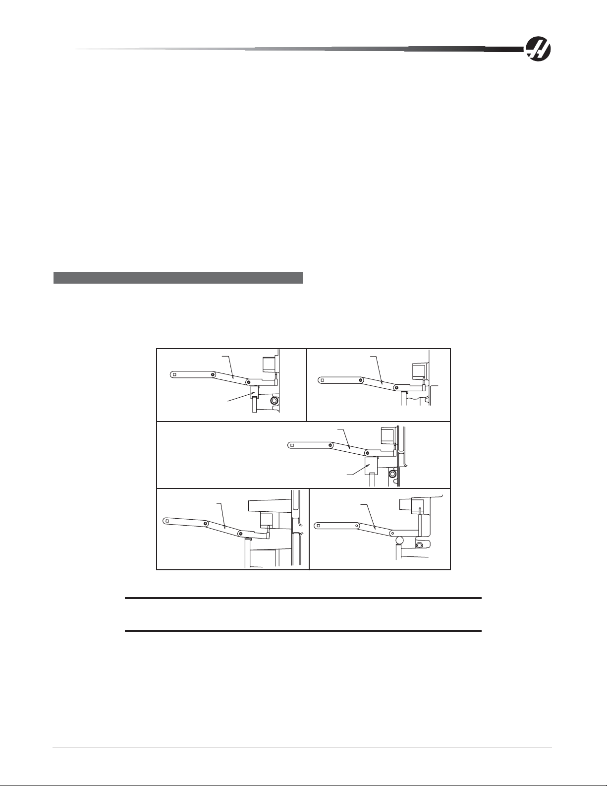
VERIFYING BELT TENSION (LATHE)
1. Apply proper tension to belt s by wedging the T -shaped belt tensioner tool underneath the spindle head
casting web, between the spindle head pulleys and motor/gearbox pulleys and the motor/gearbox mounting
plate. Att ach the 1/2" drive torque wrench to tensioner tool and apply required torque value. The path of the
applied torque should be inline with the motor assembly . A belt tensioning chart follows.
T-1537
T-1961
SL 20/20B
95 ft-lb
T-1537
SL 30/30GB
(New Spindle Center Line)
From 11/98
95 ft-lb
T-1537
SL 30B
230 ft-lb
(Encoder Pulley
Must be Removed)
T-1537
HL-3/-4 & HL-3/-4GB
Through 10/98
95 ft-lb
T-1961
T-1650
SL 40/40B
230 ft-lb
2. While applying correct torque amount, tighten the four mounting motor/gearbox plate bolts.
CAUTION! This procedure should be performed with two service persons;
one to apply torque, the other to tighten bolts.
3. Use a Gates Sonic Tension Meter to measure the belt tension.
4. Mount the encoder onto the spindle housing below the spindle shaft with four mounting bolts.
96-0283 rev A June 2006
Mechanical Service
29
Page 31

5. Place the 3/8" timing belt on the spindle pulley, with the other end on the encoder pulley.
6. Align and att ach the hydraulic cylinder adapter onto the spindle shaft with the mounting bolts. Tolerance on
the face of the adapter plate perpendicular to centerline should be within .001". Check tolerance of large
I.D. bore circular to within .002".
7. Slide the hydraulic cylinder into spindle shaft. Insert and snug the mounting bolts.
8. Att ach and clamp the oil drain hose and coolant drain hose onto hydraulic cylinder . Att ach and screw in
clamp and unclamp hoses.
9. Set magnetic base on top of the spindle housing with indicator touching the top of the hydraulic cylinder.
10. Spin the hydraulic cylinder and verify that the runout is under 0.001". If runout is over 0.001", rotate the
hydraulic cylinder to its high point and tap cylinder with a rubber mallet. Tighten and torque the bolts.
1 1. Replace all previously removed sheet metal.
SUB SPINDLE MOTOR BELT REPLACEMENT
1. Remove all sheet met al covering the sub spindle motor.
2. Remove the chuck and unhook the hoses to the union.
3. Disconnect the electrical wiring to the encoder .
4. Loosen the set screw that holds the encoder to the motor shaft.
5. Remove the screw that holds the encoder bracket to the motor .
6. Loosen but do not remove the four sub spindle motor mounting bolts.
7. Remove and replace the motor belt.
8. Reassemble in reverse steps to remove. Make sure the motor wiring is connected and secured properly .
30
Mechanical Service
96-0283 rev A June 2006
Page 32

SPINDLES
Operation
Spindle speed functions are controlled primarily by the S address code. The S address specifies RPM in
integer values from 1 to maximum spindle speed (Parameter 131).
Speeds from S1 to the Parameter 142 value will automatically select low gear, and speeds above Parameter
142 will select high gear. Two M codes, M41 and M42 can be used to override the gear selection; M41 for low
gear and M42 for high gear. Low gear operation above S1250 is not recommended. High gear operation below
S100 may lack torque or speed accuracy. Spindle speed accuracy is best at higher speeds and in low gear.
If there is no gear box in your machine, the gear box is disabled by parameters and is always in high gear. M41
and M42 commands are ignored.
The spindle is hardened and ground to precise tool holder dimensions providing an excellent fit to the holder.
Live Tooling
Live tooling provides the ability to utilize standard 40mm VDI-driven tools, operated by a 5HP motor. This
auxiliary motor is capable of 0-3000 RPM, controllable in 1 RPM increments. Live tool motor speed is controlled primarily by the P address codes. The P address specifies RPM in integer values from 1 to the maximum spindle speed of 3000 RPM.
15K & 50 TAPER HIGH SPEED SPINDLE
Non-Serviceable, Anti-Rotation Draw Bar
The draw bar and the spindle are not serviceable as separate items on the 15K spindle. The 15K spindle uses
an extra high clamp draw bar and may be used in both TSC and non-TSC applications. If there is a need to
replace the spindle or the draw bar, the entire spindle must be replaced.
NOTE: The spindle and the draw bar are balanced at the factory as a matched
assembly.
The anti-rotation draw bar does not allow the draw bar to turn in the spindle shaft. By not changing the position
of the draw bar, changes in vibration output of the spindle are minimized. The balance is also retained when the
draw bar does not turn.
Oil Flow
The specification for oil flow is 0.15 - 0.18 cc per 0.5 hour when measured from the spindle restrictor with no
airflow. This oil flow is measured on each machine. The flow rate is adjusted by changing the restrictor used
and by changing the total output of the pump. The pump nominally puts out 3 cc per 0.5 hour. The pump has a
0.5 hour cycle time. The pump runs only when the spindle is running or one of the axes is moving. Different
sized restrictors are used to control flow. A 3/0 restrictor has twice the flow of a 4/0, which has twice the flow of
a 5/0 restrictor.
STALLING/LOW TORQUE
Generally, complaints of stalling or low torque relate to incorrect tooling or machining practices. A spindle that
is tending to seize will yield a poor finish machining, run very hot and very loud. Investigate machining problems
before concluding the problem exists with the spindle or spindle drive.
SPINDLE DRIVE
Low line voltage may prevent the spindle from accelerating properly. If the spindle takes a long time to accelerate, slows down, or stays at a speed below the commanded speed with the load meter at full load, the spindle
drive and motor are overloaded. High load, low voltage, or too fast accel/decel can cause this problem.
96-0283 rev A June 2006
Mechanical Service
31
Page 33

A resistor bank (regen resistors) located on the top of the control cabinet is used by the spindle drive to
dissipate excess power caused by the regenerative effects of decelerating the spindle motor . If the spindle
motor is repeatedly accelerated and decelerated in rapid succession, this resistor will get hot. In addition, if the
line voltage into the control is above 255V , this resistor will begin to heat.
There is an overtemperature sense switch mounted near the regen resistors. This sensor is a normally-closed
switch that opens at about 100
0
C. It will generate an alarm and all motion will stop. Af ter the overheat time
period specified by Parameter 297, an automatic shutdown will occur in the control.
If the regen load resistors are not connected or open, it may result in an overvoltage alarm. A functional resistor
will have a reading of 8 ohms.The overvoltage occurs because the regenerative energy being absorbed from the
motor while decelerating is turned into voltage by the spindle drive. If this problem occurs, the possible fixes are
to slow the decel rate or reduce the frequency of spindle speed changes.
32
Mechanical Service
96-0283 rev A June 2006
Page 34

SPINDLE TROUBLESHOOTING
NOT TURNING
Spindle not turning
• If there are any alarms, refer to "Alarms" section.
• Check that the spindle turns freely when machine is off.
• If motor turns but spindle does not, see the "Belt Replacement and Tensioning" and "Spindle Motor and
Transmission".
• Command spindle to turn at 1800 RPM (vert & horiz) and check spindle drive display. If display blinks “bb”,
check spindle orientation switch.
• If spindle drive does not light the Run LED, check forward/reverse commands from I/O PCB.
• Check the wiring of analog speed command from MOTIF PCB to spindle drive (cable 720).
• If spindle is still not turning, replace MOCON PCB.
• If spindle is still not turning, replace spindle drive.
• Check for gearbox or motor rotation (if applicable). If the motor or gearbox operates, check the drive belt.
• Disconnect the drive belt (vert). If the spindle will not turn, it is seized and must be replaced.
NOTE: Before installing a replacement spindle, the cause of the previous failure must
be determined.
NOISE
Check the tooling (mills); balanced tooling will run smoother; possibly reducing the noise.
Check for misalignment between the motor and the spindle. If misalignment is noted, loosen the motor mount-
ing bolts, run the spindle at 1000 RPM, and then tighten the mounting bolts.
Remove the coolant union and run the spindle, if the spindle is quieter, the coolant union may need replacing.
Excessive noise coming from the spindle head area
Most noises attributed to the spindle actually lie in the motor/gearbox or drive belt of a machine. Isolate the
sources of noise as follows:
On Vertical VF-1 thru 6 models, first determine if the noise is related to the RPM of the motor or the RPM of
the spindle. For example: if the noise appears at 2000 RPM in high gear (40T and 50T), listen for similar noise
at 500 RPM (40T) or 620 RPM (50T) in low gear. If the same noise persists, the problem lies with the gearbox.
If the noise disappears, the problem could be either the gearbox or spindle, and further testing is necessary .
NOTE: 40 Taper gear ratio is 1:1.25 in high gear, and 3.2:1 in low gear.
• Remove the vertical head covers or lathe left end covers and check the machine’s drive belt tension.
• If the noise persists, turn the drive belt over on the pulleys. If the noise is significantly different,
the belt is at fault. Replace the belt ("Belt Replacement and Tensioning" section).
50 Taper gear ratio is 1:1.02 in high gear, and 3.16:1 in low gear.
• If the noise does not change, remove the belt and go on to the next step.
• Check the vertical machine pulleys for excessive runout (more than 0.003" axial or radial).
• Run the motor or the gearbox with the drive belt disconnected. If the noise persists, the problem lies with
the gearbox/motor. If it disappears, go on to the next step.
96-0283 rev A June 2006
Mechanical Service
33
Page 35

• Check for the correct amount of lubrication to the spindle bearings in an air mist-lubricated spindle. There
0.5-1.0 cc every two hours for the mills and 1.0 cc every two hours for the lathe.
• If the spindle is not getting lubrication, correct the problem per the lube and air diagram at the back of
this manual and replace the spindle ("Spindle Assembly" section).
• If the spindle is getting lubrication, replace the spindle ("Spindle Assembly" section).
Note: Haas Automation does not honor warranty requests for gearbox or spindles
without vibration analyzer signatures.
OVERHEATING (MILLS)
When investigating complaints of overheating, a temperature probe must be used to accurately check the
temperature at the top of the spindle taper . The temperature displayed on the Diagnostics page is not relevant.
A machine that runs at high continuous RPM will have a much warmer spindle than a machine that runs at a
lower RPM. New spindles tend to run much warmer than spindles that have already been run-in. In order to run
a valid test on a new spindle, ensure that it is properly run-in. To run-in a new spindle, run program #O02020 (it
will take approximately 6 hours):
NOTE: This program steps the spindle speed from 300 RPM up to 7500 RPM (or max
RPM) at regular intervals of time, stop the spindle and allow it to cool to room
temperature, then restart it so the temperature can be monitored.
Y ou may also use an alternate 2-hour spindle run-in program (#O02021) with the air pressure to the spindle at
30 psi. If possible run the program overnight by changing M30 to M99 so it can repeat. Adjust spindle speed
override depending on maximum spindle speed of machine: set at 50% for 5K RPM machines, 100% for 7.5K,
8K, and 10K, RPM machines; set at 120% for 12K RPM machines; set at 150% for 15K RPM machines.
• If spindle temperature rises above 150°, start the procedure over from the beginning and follow the steps
below. If the temperature rises above 150° a second time, contact your dealer.
NOTE: Once the run-in program is complete, reset the air pressure back to 25 psi.
(15K set to 20 psi) prior to checking spindle temperature.
If the spindle fails this test for any reason, check the following:
• Check for correct amount of lubrication. Over lubrication is a common source of overheating. Check the
oil flow carefully .
• Ensure that the correct oil is being used, see the "Maintenance” section of the Operator manual.
TOOLS STICKING IN SPINDLE TAPER (MILLS)
This problem may occur after loading a cold tool into a hot spindle (a result of thermal expansion of the tool
holder inside the spindle taper). It may also occur due to heavy milling, milling with long tooling, or cuts with
heavy vibration. This also is the result of thermal expansion.
If sticking only occurs during these situations, check your application to ensure proper machining techniques
are being used; check the feeds and speeds for the tools and material being used. If a tool is pulled out of the
extractors due to a tool stuck in the taper , the unclamp switch is not adjusted correctly or is bad.
NOTE: In a proper working system the spindle will pop slightly during a tool change.
This popping is normal provided it does not create flex in the double arm or
the need to remove the tool with a mallet.
• Check the condition of the tooling, verifying the taper on the tooling is ground and not turned. Look for damage
to the taper caused by chips in the taper or rough handling. If the tooling is suspected, try to duplicate the
symptoms with known-to-be-good tooling.
34
Mechanical Service
96-0283 rev A June 2006
Page 36

• Check the condition of the spindle taper. Look for damage caused by chips or damaged tooling. Also look for
damage, such as deep gouges in the spindle taper caused by tool crashing.
• Duplicate the cutting conditions under which the deflection occurs, but do not execute an automatic tool
change. Try to release the tool using the tool release button. If sticking is observed, the deflection is not
caused by improper ATC adjustment, but is a problem in the spindle head on the machine.
• Ensure the spindle is not running too hot (140°F [60°C] or above).
• Check air supply. Max air pressure drop of 10 psi [69 kilopascals] during a tool change is allowed.
• Check draw bar height adjustment (mills).
• Does the tool tip to the spindle gauge line exceed 3.5”? If so, check machining practices.
• Are the correct pull studs being used?
Tool Holder/Spindle Fretting
Fretting is the result of sideways movement of a tool holder in the spindle. Fretting can leave a wave pattern on
the mating surfaces and will affect the fit and finish of both the tool holder and the spindle.
• If light fretting is present, check the application to ensure proper machining techniques are being used;
check the feeds and speeds for the tools and material being used.
• Check pullstuds for dimpling.
• Light fretting and rust may be cleaned from the tool holder with a fine scotchbrite hand pad and solvent. If
scotchbrite is used, clean the tool holder and spindle taper thoroughly after use with an alcohol pad. Apply
a thin coat of light oil to the taper of the tool holder. Grease the pull stud.
CHECKING SPINDLE OIL FLOW (VERT)
Disconnect the air/oil line to the spindle at the lube-air panel (30K 30 Taper and 15K GR-Series are discon-
nected at the check valve). Install a short piece of hose into the port on the regulator and place the other end
into a graduated cylinder. Lower spindle air pressure regulator to 0 p si. Program a repetitive machine axis
movement (do not run the spindle) and note the amount of oil collected. The program should be allowed to run
for four hours. Reset the spindle air pressure regulator to proper pressure, once completed.
NOTE: Use 5% or 25% rapid for axis movement. Moving the axes faster will not change
the results.
The following gives the range for each type of spindle:
40 Taper (7.5K and 10K) 1.5 to 2.5 cc every four hours
15K 40 Taper 1.1 to 1.4 cc every four hours* For GR-Series machines see below.
50 T aper 1.7 to 2.1 cc every 4 hours
30K 30 Taper* *Airmatic Pumps (These pumps are identified by the addition of a solenoid on
top of the pump) The 30K 30 taper and the GR series 15K or higher spindle
use this type of pump.
Airmatic Pumps
Disconnect the air/oil line at the check valve. Manually energize the solenoid 30 times, holding it for 2 seconds
each time.
Each pulse from the pump will deliver .01 cc for the 30K 30-taper, or .2cc for the GR 15K. After 30 pulses, .3 cc
30K or 6cc 15K, should have been collected per injector (the 30K spindle has two injectors).
96-0283 rev A June 2006
Mechanical Service
35
Page 37

SPINDLE ASSEMBLY
Please read this section in its entirety before attempting to replace spindle.
WARNING!
The pulley is shrink-fitted onto the spindle and is not fieldserviceable. It is identified by many holes on top of the spindle
pulley. Should any attempt to remove the pulley damage the
spindle or its components, the service warranty will be voided.
NOTE: Adjust drive belt tension after transmission or spindle service.
SPINDLE REPLACEMENT (HORIZ & VERT)
NOTE: VMCs equipped with a 15K Spindle must remove the spindle and draw bar as
a unit. Do not remove the draw bar separately.
Removal
1. Ensure the machine is On, and remove the spindle head cover/panels.
On belt drive spindles (not 15 or 30K or inline drive)
HORIZ only: Remove the six SHCS that mount the spindle to head casting and slide the spindle out from
the front side of machine.
2. Put the tool into the spindle and remove any covers necessary to access the spindle.
3. Remove the tool release piston assembly in accordance with appropriate section and remove the spindle
drive belt from the spindle pulley . It is not possible to completely remove the belt at this time.
4. Draw bars are held in the spindle shaft by a spiral ring (newer assemblies). 30K spindles: The draw bar is
not serviceable. Remove the spiral ring with a small screwdriver. W edge the tip of the screwdriver to take
out one end of the ring from the shaft groove. Force the ring end to stay open and simultaneously rotate the
screwdriver all the way around so the entire ring comes out of the groove.
5. Put the tool release piston on and remove the tool. First disconnect the oil line from the fitting at the oil
injection cover, then remove the brass fitting.
NOTE: When replacing a new design spindle in any vertical machine, it is important
to note that the cavity between the housing and the spindle cartridge will be
filled with either oil or grease. An oil filled spindle is identified by the oil fill hole
to the left side of the spindle head near the spindle bore as viewed from above.
6. Ensure oil plug is inserted into oil injection port of spindle before removing spindle, or oil may spill into the
spindle cartridge.
7. In-line drive and 30K spindle s: Remove the hose & oil fitting on the spindle and plug the oil-fitting hole(s)
with the set screws from the new spindle.
8. Remove the spindle drive belt from the spindle pulley .
9. With 5/16" hex wrench, loosen the six SHCS that hold the spindle to the underside of the head casting
approximately 2 turns.
36
Mechanical Service
96-0283 rev A June 2006
Page 38

Z-Axis
Wood Block
6" min.
Position W ood Block Under Spindle
Covered
Table
10. Put a wood block (minimum 6" thick) on the table directly under the spindle to help support the spindle.
11. Slowly jog the spindle head down until the spindle rests on the block.
12. Remove the 6 bolts from the spindle.
13. Jog the Z-axis up slowly.
In-line drive: Remove spider coupling and transfer tube from the spindle or motor. Check these two
components for any irregularities, and replace if needed.
14. Grasp spindle with one hand and continue to jog in Z in the positive (+) direction until it is completely free
of the casting.
Installation
Tool Drawbar
Front
Spindle
Housing
Spindle
Pulley
Tool Drawbar
Spindle
Housing
Spindle
Pulley
10 - 32
Holes
30K Spindle Cartridge Vertical Spindle Cartridge Underside View of Vertical Spindle Cartridge
In-line drive: Loosen the motor mounting plate bolts (4 bolts), and loosen the motor mounting bolts under
the plate (4 bolts).
1. Thoroughly clean all mating surfaces of both the cartridge and the head casting, and lightly stone (if
necessary) to remove burrs or high spots.
2. Mount the new spindle to the block. HORIZ only: Carefully install the new spindle into the bored sleeve of
the head casting. Apply grease to the inside of the through bore in the spindle head. The oil drain hole
must point down. Failure to do so causes the spindle to overheat, fail, and voids the warranty .
96-0283 rev A June 2006
Mechanical Service
37
Page 39

Spindle
Assembly
6X SHCS
6X Lockwasher
EC-300
Spindle Head
Assembly
EC-400
Spindle Head
Assembly
1/4” Tube X 1/8” NPT
1/4” Tube X
1/8” NPT
Spindle must be installed
with oil drain notch in
spindle lock at the bottom
HORIZ only: Evenly tighten the six mounting SHCS on the front side of the spindle in a cross pattern
until all bolts are completely tight.
HORIZ only: Reset spindle orientation and check the tool changer adjustment.
HORIZ only: Refer to "Spindle Troubleshooting - Overheating" and use the spindle run-in program. Verify
that the spindle temperatures are acceptable.
3. Align the two 10-32 holes located on the spindle lock so they are approximately 90° from the front of the
spindle on the right side.
In-line drive: Install set screw plug into the oil fitting. This will prevent contamination to the bearings. Put
grease on the o-ring of the transfer tube and install the transfer tube on the new spindle. Install spider
coupling on spindle. Orient the motor and spindle couplers.
4. Slowly jog the Z-axis down until the top portion of the spindle is inside the head casting. At this point, align
spindle to the spindle bore. While performing this operation, you must make sure the spindle cartridge is
straight to the spindle bore. If the spindle moves to one side, use a rubber mallet and/or the axes to align
it. The spindle should slide into the casting easily. If not, check your alignment. Do not force it!
5. Install the spindle bolts and torque to 50 ft-lb.
6. Vert: Re-attach the brass fitting to the oil injection cover and connect the oil line to the fitting. Fill the cavity
between the housing and the spindle cartridge with Mobil V actra 2 oil. The oil fill hole is to the left side of
the spindle head near the spindle bore, as viewed from the top.
30K Spindle Quick Disconnect Fittings to Oil Injection Cover
CAUTION! Do not overtighten the fittings when replacing on the oil injection
cover. Overtightening may damage the spindle cartridge.
NOTE: If replacing copper tubing to spindle, clean out with filtered air.
7. In-line drive: Take the spindle sweep on the table and shim if needed. Loosen the spindle bolts again just
for spindle and motor alignment. Remove set screw plug, install oil fitting, and connect the hose. Do not
overtighten fittings.
38
Mechanical Service
96-0283 rev A June 2006
Page 40

8. In-line drive: Command the spindle to 300 RPM. Carefully tighten the motor bolts, and the motor mount-
ing bolt under the motor plate (80 ft-lb). Tighten the spindle bolts evenly to 50 ft-lb. Stop spindle and check
by hand for binding. If there is no binding, refill spindle orifice with V actra Oil #2.
WARNING:
Never pour oil into the spindle housing. If binding is felt, loosen
the motor mount bolts and go back to step 7.
9. Vert: Reinstall the drive belt and adjust the tension. Reinst all the tool release piston assembly .
10. Vert: Remove the tool release piston. Carefully inst all the spiral ring on the spindle shaft. Feed one end of
the spiral ring into the shaft groove. Rotate the ring until the entire ring is in the groove. Check the spindle
sweep and clamp/unclamp switch adjustment.
11. In-line drive: Verify the spindle air/oil regulator is set to 20 psi.
12. In-line drive: In MDI, write a program to move the machine axis at 5 inches per minute.
13. a. In-line drive: Disconnect the oil fitting from the air/oil mixer that feeds directly to the spindle. Use a
graduated cylinder to verify the correct amount of oil is getting to the spindle (1.1 cc to 1.4 cc per 4 hours). If
necessary , change restrictors to change oil flow . Do not adjust oil pump volume. If any changes are made,
run the test again.
b. Vert: Check for correct amount of lubrication to the spindle bearings (0.5-1.0 cc every two hours) in an air
mist-lubricated spindle.
• If the spindle is not getting lubrication, correct the problem and replace the spindle.
• If the spindle is getting lubrication, replace the spindle.
NOTE: Refer to the appropriate sections and check the spindle orientation and ATC
14. In-line drive: Check draw bar and adjust the tool clamp/unclamp limit switches.
alignment.
SETTING THE DRAW BAR HEIGHT
Horizontal Machines
Draw bar height must be set properly before adjusting switches. Add or subtract shim washers to the tool
release piston until proper height is achieved (see “Setting TRP Height”).
Vertical Machines
1. Power on the mill.
2. Set the TRP air pressure regulator to 40 psi.
3. Place a sheet of paper on the mill table under the spindle for protection, then place an aluminum block
(approx. 4” x 4” x 4”) on the paper.
4. Insert an empty tool holder in to the spindle.
5. Jog the spindle down so that the tool holder is approximately .03” above the block.
6. Set the clearance from the block to the tool holder to zero. Do this by pressing “Tool Release” and jogging
the Z-axis with the jog speed set to .001".
7. Move the axis, then press the T ool Release button while feeling for movement on the tool holder . Feel
between the tool holder and the spindle. Repeat this process until no movement is felt.
8. Change the jog speed to .01 and jog the Z-axis to .060" above the block.
9. Press and hold the Tool Release button. Try to move the block. The block should be tight at .050" and
loose at .060". If it can be moved at .050", jog the Z-axis towards the block one increment at a time until it
is tight. If it is tight at .060", jog the Z-axis away one increment at a time until it is loose.
96-0283 rev A June 2006
Mechanical Service
39
Page 41

10. The number of increments jogged up or down are the number of shims to add or remove. If the block was
tight at .060", remove shim washers. If the block was loose at .050", add shim washers.
Lower TRP Unclamp Switch
1. With an empty tool holder in the spindle, and the jog speed set to .001”, jog the Z-axis down until the
aluminum block is pinched against the table. Jog back up .030”.
2. Bolts holding the lower switch must be loose so the switch can slide in and out for proper adjustment.
3. Go to the Discrete Inputs page on the control and find Draw Bar Open.
4. Press and hold the Tool Release button. Slide the switch towards the piston until the switch trips. This is
verified on the control and Draw Bar Open should read 1. Tighten the screws that secure the switch.
5. Release the Tool Release button and verify that the switch trips (Draw Bar Open = 1) at .030" above the
block and not tripped (Draw Bar Open = 0) at .020" above the block.
Upper Clamp Switch
Push the switch in slowly until it trips (Draw Bar Closed = 1). Tighten the bolts to secure the switch.
Final Checks
TRP Air Pressure - Set TRP air pressure regulator to 50 psi.
Perform the Spindle Run-in Program
Run program O02023. As the spindle is running, check for proper oil flow. Periodically check the temperature of
the spindle. Stop the program if the spindle begins to overheat.
CAUTION! Never run the spindle without a tool holder in the spindle. Running the
spindle without a tool holder will damage the spindle.
Belt Tension
The belt may whip during acceleration and deceleration but should not when a constant speed has been
reached. Check the behavior of the belt at different speeds, throughout the RPM range. If the belt whips while at
a constant RPM, adjust the belt tension.
DRAW BAR REPLACEMENT
Removal
NOTE: Should a spindle fail, both the spindle and draw bar are to be replaced as a
unit. If the draw bar fails, it is not necessary to replace the spindle.
In-line: The draw bar is replaceable on the 8K spindle, not on the 12K spindle.
NOTE: VMCs equipped with a 15K Spindle must remove the spindle and draw bar as
a unit. Do not remove the draw bar separately.
1. Place a tool holder with no cutter in the spindle.
In-line: Remove motor.
2. Remove the necessary covers to access the spindle.
3. Remove the TRP. In-line: Remove the key from the draw bar and remove from spindle.
4. Remove the snap ring from the top of the spindle shaft.
50 taper: Remove the TSC extension tube if the machine is equipped with the TSC option. Refer to the
“Spindle TRP Removal” section.
5. Reinst all the TRP. Remove the tool holder from the spindle, then remove the TRP again.
40
Mechanical Service
96-0283 rev A June 2006
Page 42

50 taper: Remove six bolts holding the spindle cap to the machine and remove the draw bar .
40 taper: Remove bolts from the transmission and use 2” x 4” blocks of wood, placed underneath the front
of the transmission housing, to keep it from falling forward. Angle the transmission back and remove the
draw bar from the spindle.
NOTE: Direct drive machines do not require movement of the drive assembly to
access/remove the draw bar.
Installation
6. Thoroughly coat the replacement draw bar with grease, including the end of the shaft where the four holding
balls are located.
CAUTION! Excess grease may cause the draw bar to hydraulic lock preventing the full
stroke of the draw bar.
7. Install the two keys, flat side up. Use a “C” clamp to press the keys together to seat them against the draw
bar. T orque the 5/16-18 retaining bolts to 30 f t-lb.
Transfer Tube
Coupler Spider
Coupler Hub
Draw
Bar
Shaft
ShaftAdapter
Horizontal Draw Bar
8. If machine is equipped with Through the Spindle Coolant option, grease the o-rings.
9. Insert four new balls (six new balls for 50 taper) in the replacement draw bar and insert into the spindle
shaft. Be sure that as the shaft is installed, the balls do not fall out of the bores in the draw bar.
CAUTION! Insert draw bar so the o-rings are not damaged. Do not force it.
NOTE: Carefully inspect the spindle shaft for galling or burrs inside the spindle shaft
where the end of the draw bar rides. If it is damaged, replace the spindle.
10. 40 Taper: The tool release piston will have to be reinstalled at this time; therefore, inst all a tool holder with
no cutter into the spindle taper . Remove the tool release piston and install the spiral ring on the spindle
shaft. Reinstall the tool release piston.
11. Set the draw bar height, and clamp/unclamp switches as described in the following section. Install the
draw bar and re-install the tool release piston.
12. Reinstall the sheetmetal.
13. T est-run the machine and perform necessary A TC adjustment s. Verify the operation of the spindle by
running it. If there is excessive vibration, loosen the bolts to the spindle cartridge and spindle head. Run the
spindle at 1000 RPM and snug the bolts. Stop spindle and tighten bolts.
96-0283 rev A June 2006
Mechanical Service
41
Page 43

Mill Spindle Sweep Adjustment
NOTE: The machine must be properly leveled for the spindle sweep adjustment to be
accurate.
1. To check spindle sweep, place a .0005 indicator on a suitable holder, place on spindle nose and jog the Z-
axis in the negative (-) direction enough so that you can adjust the indicator to sweep a 5" radius from the
center of X- and Y-axis travel. Slowly jog Z-axis in the negative (-) direction to zero out indicator.
2. Establish a reference point (indicator zero), sweep the three remaining points and record the reading.
10" dia.
circle
Spindle Sweep Area
3. Shim the spindle, if necessary, to correct the spindle sweep to specifications.
4. Recheck sweep. It must be within .0005 in both X/Z and Y/Z planes, as stated in the inspection report
supplied with the mill.
Horizontal Spindle Sweep Adjustment
NOTE: The machine must be properly leveled for the spindle sweep adjustment to be
accurate.
1. Place an indicator on the table and insert a 6" precision test bar into the spindle.
2. Jog the Z-axis while indicating the bottom, then the side, of the test bar. The readings must be within
0.0005/10" in both the Y/Z and X/Z planes, as stated in the inspection report supplied with the machine.
3. Shim the spindle, if necessary, to correct the spindle sweep to specifications. Recheck spindle sweep.
Z
Y
z
x
42
Mechanical Service
96-0283 rev A June 2006
Page 44

SPINDLE ORIENTATION
Please read this section in its entirety before attempting to orient the spindle.
Orientation of the spindle is automatically performed for tool changes and can be programmed with M19.
1. Place the machine in low gear .
2. Adjust Parameter 257, "Spindl Orient Ofset", until the spindle dogs are parallel to the X-axis. Ensure that the
dogs are within 0.030" using a dial indicator .
For 50 taper mills with an offset tool changer: Add a 5° offset (111 encoder steps) to Parameter 257 to
match the tool changer arm offset.
A, B AXIS RE-ALIGNMENT (VERT)
Gimbaled head mills only - If tramming the A/B axes is necessary, sweep a 10” diameter circle on the table
with a dial indicator mounted to the spindle. To select A or B axis when in the jog mode, use the shif t key on
the keyboard, then select A or B axis. The display will indicate which axis is enabled. It is recommended that
when jogging the A and B axes, the operator use only the .0001, .0010, or .0100 increments.
The rule of thumb is that for every .001” out of position, you add or subtract 100 from the appropriate parameter .
This will re-calibrate the distance from the A/B axes home switch. Parameters 212 and 213 are the tool change
offset parameters for the A- and B-axis. These parameters also control the tram of the A-axis and B-axis. It is
advised that you record the factory set values before changing parameters 212 and 213 in the event that you
enter an invalid number and have to start over .
When adjusting the tram, it is recommended that you use same feedrate to home the A/B axes between
checking the sweep. This will allow the machine to repeat more accurately . The A-axis and B-axis should be
trammed individually to reduce the possibility of error.
96-0283 rev A June 2006
Mechanical Service
43
Page 45

LATHE SPINDLE ASSEMBLY
LATHE SPINDLE REMOVAL
NOTE: Power off the machine before performing the following procedure.
Mini Lathe (ML): Remove the door, the coolant collector from the spindle, and the left front and left side
enclosure panels. Disconnect the air/oil lube lines that supply the spindle and the air closer .
1. Remove the chuck or collet nose from the Lathe and the necessary covers to gain access to the spindle
assembly. ML: Remove the work holding device, air closer , adapter , and drawtube (by screwing it out).
TL: Remove sheetmetal panel from the left side of the machine casting. This will gain access to the
spindle motor and belt.
TL: Remove the belt from the spindle pulley . To do this loosen the three bolts on the motormounting
plate (see the spindle motor removal section). Use a bottle jack to lift the motor mounting plate. This will
gain slack in the belt so it can be removed from the pulley.
ML: Remove the belt from the drive pulley . Attach a hydraulic puller to the drive sprocket.
TL and ML: Remove the SHCS that secure the spindle front cap to the spindle housing and remove the
spindle cartridge from the motor end of the spindle housing.
2. Disconnect oil return hose and coolant drain hose from the hydraulic cylinder.
3. Loosen the clamp and unclamp hoses, then remove.
4. Loosen the SHCS from the adapter, and detach the hydraulic cylinder.
5. Loosen the SHCS on the inside of adapter, and detach from spindle shaft.
Adapter
Oil return hose
Hydraulic cylinder
Clamp/Unclamp
hoses
Coolant
collector
Coolant
drain hose
Hydraulic Cylinder
6. Unplug the encoder. Unscrew the encoder bracket, remove the encoder, then remove the belt.
7. Loosen the four SHCS holding the spindle motor. Slide the motor up by squeezing the belts. Tighten
the SHCS and remove the drive belts from the spindle assembly.
8. Loosen the six SHCS and remove the spindle drive pulley.
9. Disconnect the two lubrication hoses and unscrew the fittings from the spindle housing. Note the direction
of the flat sides of the fittings for lubricating the spindle bearings.
44
Mechanical Service
96-0283 rev A June 2006
Page 46

10. Unscrew the SHCS holding the spindle retaining ring (located at the spindle nose) and remove. Also
remove the o-ring.
1 1. Remove the spindle carefully through the machine front.
Adapter
Clamp/Unclamp
Hoses
SL-10 Hydraulic Cylinder (Coolant Collector not Shown)
SPINDLE INSTALLATION
T ools Required: Blue Loctite, 1/2" Torque Wrench (Up to 250 ft-lb), Haas Belt Tensioning Tool P/N 93-8143
(SL 20), P/N T1537 (SL 30 and 40)
1. Inspect the new spindle once it is removed from the packaging. Check the alignment of the spacer between
the two bearings. Use a dial indicator on the spacer and bearings to check the run-out. Also verify the axial
run-out on the face of the bearing, which should not exceed .0004".
2. Install spindle into housing. Check location of oil holes for proper alignment.
96-0283 rev A June 2006
Mechanical Service
45
Page 47

3. Place the retainer ring on the spindle with the o-ring toward the spindle. Ensure that the drain holes are at
the bottom of the retainer ring and that the o-ring remains in place.
4. Apply blue Loctite to the six retainer ring mounting bolts and install them.
NOTE: The bolts should be torqued in a star pattern and in increments of 10, 20, 30,40
and finally 50 ft-lb. Check alignment of the spindle and retaining ring with a
.001" shim at each torque value.
Spindle retainer
Housing
bolts (6)
Drawtube
Align Oil Holes (2)
Spindle
Oil Nozzles (2) to 10 psi
Spindle Retaining Bolts Alignment of Oil Mist Holes
5. Ensure that the spindle can spin freely and the spindle and housing oil mist holes are aligned. If not,
remove the retainer ring and spindle and reinstall.
6. Screw the oil mist nozzles in by hand until they stop. Then un-screw the nozzles 1.5 - 2 turns, ensuring
that the holes on the nozzles and spindle housing are aligned correctly and pointed toward the bearings.
Make sure the nozzles do not come into contact with the spindle shaft.
7. Tighten the hex nut on the nozzles, ensuring the nozzles do not spin. After tightening the nuts, verify the
nozzle oil mist holes are still positioned correctly, and set the oil pressure to 10 psi..
8. Attach the two 1/4" nylon tubes onto the swivel fittings.
9. Install the spindle drive pulley , and drive belts onto the spindle and motor pulleys.
OFFICE MILL SPINDLE BREAK-IN
NSK Spindle
The spindle run-in program must be run prior to machine use and especially at the time of installation. Failure
to run this program can result in spindle over heating and spindle failure. The run-in will distribute grease which
may have settled in the bearings during shipping. The program is #O02027 (SPINDLE RUN-IN) and will take
approximately fifty (50) minutes to run. During this time, verify spindle rotation. The spindle should be checked
periodically for spindle temperature rise. If the temperature rises above 140°F, restart the program from the
beginning. If the temperature again rises above 140°F, contact your dealer.
NOTE: Do not tighten the collet without mounting a tool or “dummy bar” as this will
damage the collet, spindle, and collet nut.
40K, ISO20 Spindle
The spindle run-in program must be run prior to any machining use (especially upon installation or after any
transportation). Failure to run this program can result in spindle over heating and spindle failure. The run-in will
distribute grease which may have settled in the bearings during shipping. The program is #O02025 (SPINDLE
RUN-IN) and will take approximately six (6) hours to run. During this time, verify spindle rotation.
46
Mechanical Service
96-0283 rev A June 2006
Page 48

IMPORTANT: A balanced ISO20 toolholder must be in the spindle during run-in and/
or warm-up.
TOOL ROOM LATHE SPINDLE MOTOR
Removal
NOTE: It will take two people to lower the motor mount plate, motor, and fan from the
machine.
1. Remove the sheet metal panel from the left side of the machine casting.
2. Before removing the spindle motor make sure to stabilize the motor and fan assemblies.
3. Disconnect all electrical connections from the under side of the motor.
4. Remove the three SHCS from the mounting plate and remove the pulley belt.
5. Leave the mounting plate connected to the spindle motor and carefully remove the spindle motor, and fan.
6. Remove the four SHCS that are connecting the mounting plate to the motor, then remove the four SHCS
that are connecting the fan to the spindle motor.
Installation
NOTE: It will take two people to lift and attach the motor mount plate, motor, and fan
to the machine.
1. Attach the motor mount plate to the motor using the four SHCS, and torque the SHCS to 70 ft-lb. Attach
the fan to the motor using the four SHCS.
2. Lift the mounting plate, motor, and fan into place and fasten the plate to the casting using the three SHCS.
Do not tighten the bolts, they should be snug enough to hold the motor in place. Install the drive belt, and
check for correct tension. Tighten the three SHCS on the motor mount plate.
3. Reconnect the electrical connections on the motor, and install the sheet metal motor cover .
96-0283 rev A June 2006
Mechanical Service
47
Page 49

TL-SERIES SUB SPINDLE
SPINDLE MOTOR REPLACEMENT
1. Remove the sheet metal covering the sub spindle motor and the union.
2. Cut all plastic ties to the motor wiring. Disconnect the wiring from the motor.
3. Remove the encoder: Loosen the set screw that holds the encoder to the motor shaft. Remove the screw
that holds the encoder bracket to the motor.
4. Remove the four (4) bolts that mount the motor to the spindle head.
CAUTION! You may need to use a hoist to lift the sub spindle motor as it weights
approx. 90 lbs.
5. Install the replacement motor in reverse steps for removal. Make sure the wiring is fed beneath the belt.
SUB SPINDLE HEAD ALIGNMENT
1. Insure that the main spindle is aligned. Follow alignment procedures for Lathe Spindle Assembly.
2. Mount the spindle alignment bar (T-21 13) to sub spindle face. Before inst alling the test bar, insure that both
mating surfaces are cleaned thoroughly .
3. Mount a magnetic base and a .0001” indicator on the turret face. Rest the indicator tip on the top surface
nearest the sub-spindle face and manually rotate the sub-spindle. Tap on the alignment bar flange and
indicate it to zero runout. Jog the indicator in the Z-axis direction to the end of the alignment bar and set
the indicator to read zero. Rotate the sub spindle to check runout. runout should not exceed .0002. If the
runout exceeds .0002, then use different tension on the test bar mount bolts to adjust.
NOTE: Test bar should be indicated to .0 runout before checking alignment of
sub-spindle
4. Rest indicator tip on the top surface. Using the “Z” axis jog the indicator tip over eight inches of the test bar
to check spindle flatness, max tolerance is .0003”.
Top of Spindle Nose
Alignment Bar
Bottom of
Spindle Nose
X-axis
Z-axis
Sub-Spindle
Adjust for Flatness
(Back Shim)
Adjust for Parallelism
(Side to Side)
Adjust for Flatness
(Front Shim)
Shim Stock Location
5. If the sub-spindle is out of tolerance then shimming is necessary. See the following figure for shim stock
information and the previous figure for the location of where the shim stock will be inserted.
48
Mechanical Service
96-0283 rev A June 2006
Page 50

Shim Thickness Tables
PARTNO.
20-6460
20-6461
20-6462
20-6463
20-6464
20-6465
20-6466
20-6467
1 REF DIM
TOL: ±0.0010
0.1040
0.0840
0.0890
0.0940
0.0990
0.1090
0.1140
0.1190
0.124020-6468
'SIZE'
NOMINAL
-0.0200
-0.0150
-0.0100
-0.0050
+0.0050
+0.0100
+0.0150
+0.0200
PARTNO.
20-8812
20-8813
20-8814
20-8815
20-8816
20-8817
20-8818
20-8819
20-8820
1 REF DIM
TOL: ±0.00015
0.2300
0.2275
0.2280
0.2290
0.2295
0.2305
0.2310
0.2320
0.2325
2X.75
8.25
5.75
2.75
1
See
Reference
Table
Shim Stock Information
Repeat steps 4 and 5 until the flatness is within specifications.
6. With the indicator on the nose of the test bar, place the indicator tip on the top of the beveled lip of the
main spindle and set it to zero.
7. Rotate the bar 360° and check the concentricity of the sub spindle to the main spindle. The tolerance is
.002” TIR. Adjust side to side using set screws.
8. If the height is out of tolerance you need to change the front and back sub-spindles shims by the amount of
correction necessary , and still maintain flatness.
9. Repeat steps 5 - 9 until the Flatness and Top to Bottom Centerline tolerance are within specifications.
10. Rest the indicator tip that is riding on the top of the test bar to run along the side of the test bar. Use the Z-
axis to jog the indicator tip over eight inches of the test bar to check the sub-spindle parallelism, max
tolerance is .0003”.
1 1. If the sub-spindle is out of tolerance adjust the parallelism adjusting screws to bring it in.
Repeat steps 10 and 11 until parallelism is within specifications.
12. With the indicator on the nose of the test bar place the indicator tip on the side (90° position) of the beveled
lip of the main spindle and zero.
13. Rotate the bar 360° and check the concentricity of the sub to main spindle. The tolerance is .002” TIR.
SPINDLE HEAD ALIGNMENT
TOOLS REQUIRED: Dual Indicator Stand
Depending on lathe model, the following sheet metal pieces may need to be removed: Front left panel, front
bottom panel, drain rail, front door
1. Loosen all spindle head mounting bolts. Loosen the locknuts on the two jack screws (adjustment bolts)
underneath the spindle head casting, then screw them in to lower the spindle casting.
2. Bolt spindle alignment bar tool to spindle and attach a 0.0001" indicator onto the face of the turret. Jog
indicator such that the indicator runs tangent to alignment bar along the Z-axis.
3. Level the spindle head assembly by adjusting the jack screws up or down and jogging the indicator along
the alignment bar in the Z-axis. The tolerance reading should be .0001" within 10".
96-0283 rev A June 2006
Mechanical Service
49
Page 51

Spindle housing
Adjustment
bolts (2)
Adjustment Bolts Indicator Setup
4. Once the spindle head assembly is level, setup dual indicators on the large magnetic base and place on
the base casting to the rear. Indicate them at the machined face to maint ain the spindle head level (see
figure). This setup is to ensure the spindle remains parallel in the Z-axis plane while raising the spindle
head. It is recommended to only turn the jackscrews a quarter turn each time so that the spindle head
does not become positioned too high above the turret pocket.
NOTE: If the face of the spindle head casting is not machined, an alternate method
to set up the indicators is to retract the B-axis waycover from the left side and
mount the mag base to the base casting. Two indicators are then positioned
on the machined surface beneath the spindle head casting.
5. Place the tenths indicator at the end of the spindle alignment bar and jog the tool turret in the Z- axis
towards the spindle until the indicator rest on the inside of the tool pocket.
6. Align the tool pocket holder along the X-axis with the spindle alignment bar by rotating the spindle and
sweeping the indicator 180o along the axis (Refer to the “Turrets - Turret Alignment V erification” section).
Note that the tool holder alignment pins create a bump in the pocket that should be ignored.
7. Jog the turret along the X-axis until a measurement reading within .001" is indicated.
NOTE: Use the jog handle in tenths mode to zero pocket
8. Next, zero the spindle alignment at the top and bottom of the turret pocket by sweeping the indicator at
those positions and adjusting the jack screws equally .
9. Rotate the spindle 180oand adjust the jackscrews until the indicator reads within a .001" at the top and
bottom of pocket. Repeat Steps 6 and 7, to ensure the X-axis is zeroed for each adjustment in the vertical
direction.
10. Torque the spindle head mounting bolts to 500 f t-lb so as not to change the spindle’s position.
11. Once the pocket is zero, X-axis value on the screen becomes the new machine spindle centerline. Tighten
the jam nuts on the jack screws under the spindle head.
NOTE: The X-axis value in the Positions page is the new machine centerline. This
value should be stored in Parameter 254.
12. Repeat Step 2 to ensure that the shaft has remained horizontal. If the shaft has moved, return to Step 9
and recheck the pocket position.
13. Test the other pockets in the same way as pocket #1 (Step 9) without moving the X-axis position. The
tolerances for the other pockets are 0.003 inch from the centerline.
14. Reinstall the sheet metal pieces that were removed for this process.
50
Mechanical Service
96-0283 rev A June 2006
Page 52

SL-10 SPINDLE HEAD ALIGNMENT
1. Attach the spindle alignment bar to the spindle. Adjust the position of the alignment bar until the measured
runout at both the base and end of the bar is less than 0.0001”. To adjust the position of the alignment bar,
slightly loosen the mounting bolts and tap on the mounting end of the alignment bar .
2. Loosen the eight SHCS mounting bolts for the spindle head. Back out the two set-screws on the front side,
lower edge of the spindle head.
3. Attach a 0.0001” dial indicator to the turret. Jog the X- and Z-axes to position the dial indicator on the side
of the alignment bar.
4. Sweep down the length of the alignment bar to measure the spindle head parallelism with the Z-axis.
5. Push the spindle head towards the back of the machine. Run in the set-screws on the front, lower edge of
the spindle head until they contact the locating dowels underneath the spindle head. Adjust the spindle
head parallelism with the Z-axis using these two set-screw. The spindle head should be parallel with the Zaxis with in 0.0004”/10”.
6. Mount two travel dial indicators onto the side of the base. Place the tips at the extreme ends of the spindle
head casting. Zero the indicators.
9. Attach a 0.0001” dial indicator into the end of the alignment bar.
10. Install a boring bar tool holder into tool position #1. Ensure the bore of the tool holder is clean and free of
any burrs, chips, or other contaminants. The tool holder must be seated completely against the turret.
11. Jog the X-axis down to the original spindle centerline.
12. Jog the Z-axis until the tip of the dial indicator can be placed on the inside of the bore in the tool holder.
Sweep the bore to measure the concentricity of the spindle head to the tool position. The tool holder bore
must be concentric with the spindle within 0.001” TIR.
13. Adjust the position of the spindle head by carefully screwing in the set-screws. Ensure that the spindle
head parallelism to the Z-axis remains constant by moving the spindle equal amounts as indicated on the
two travel dial indicators.
14. Once the runout is less than 0.002” TIR, verify that the spindle head parallelism to the Z-axis is within
0.0004”/10”. Evenly torque the spindle head bolts to 300 ft-lb and ensure that all SSS in the spindle head
casting are bottomed out on the dowel pins.
96-0283 rev A June 2006
Mechanical Service
51
Page 53

GEARBOX, TRANSMISSION, AND SPINDLE MOTOR
Gearbox (Mill)
There is a double solenoid valve controlling air to the gear box. This solenoid sends air to select either the high
gear or the low gear. When power is removed from the solenoids, the valve remains in it s last state. Air is
always required to ensure the gears are held in either high or low gear. Circuit breaker CB4 will interrupt power
to these solenoids. Power is left on the solenoid which is commanded last.
Two gear box switches are used to sense the position of the gears. One switch indicates High by opening and
the other indicates Low by opening. Between gears, both switches are closed indicating a between-gear
condition. The diagnostic display shows switch status and the Curnt Comds display shows which gear is
selected. If the switches indicate the gear box is between gears, the display will indicate “No Gear”.
NOTE: The transmission high/low gear position switches are located at the bottom
of the gearbox assembly and are difficult to reach. Removal of this assembly
is necessary to replace these switches.
High gear and low gear are selected by programming an M41 (Low Gear) or M42 (High Gear). Gears will not
change automatically . The spindle will come to a complete stop when changing gears.
The machine remains in its current gear (until changed with an M41 or M42) even after the machine is powered
off. When the machine is powered up, it is in the same gear (or between gears) as when it was powered off.
The current gear status is monitored by discrete outputs SP Hig (Spindle High) and SP Low (Spindle Low). A
"0" (zero) in either of these outputs indicates it is the current gear. If the outputs are the same, neither gear is
selected. If the gearbox remains in this condition (between gears) for a certain amount of time, Alarm 126,
"Gear Fault", is generated. The only way to reset this alarm is to press the Power Up/Restart key. The current
gear can also be monitored by pressing the Curnt Comds key . This display will show whether the machine is
currently in "High Gear", "Low Gear", or "No Gear".
There are a number of parameters related to the gearbox. Their values should not be changed by the operator .
The gearbox cannot be serviced in the field and must be replaced as a unit.
Transmission (Lathe)
The Lathe spindle motor is directly coupled to the transmission, which is between the motor and the spindle
casting, The transmission is V belt-coupled to the spindle pulley . An electric motor drives the gearbox shifter
into high or low gear. The transmission cannot be serviced in the field and must be replaced as a unit. Never
remove the motor from the transmission, as this will damage the transmission and void the warranty .
TROUBLESHOOTING
Noise
Gearboxes can be damaged by gearshift cylinders, or bearings, resulting in noisy operation. While gearbox
vibration can cause a poor finish on a workpiece, noisy gearbox operation may not.
Excessive or unusual noise coming from the gearbox, transmission, and/or spindle motor.
Operate the machine in both high and low gears. Monitor for noise in both gear positions, and if the pitch of the
noise varies with the motor or the output shaft speed.
• If the noise only occurs in one gear throughout the entire RPM range of that gear position, the problem lies
with the gearbox or transmission, and it must be replaced.
• If the noise occurs in both gear positions, disconnect the drive belt(s) and repeat the previous step. If the
noise persists, the gearbox or transmission is damaged and must be replaced.
• With the drive belt(s) disconnected, run the machine in high gear. Command a change of direction and listen
for a banging noise in the gearbox or transmission as the machine slows to zero RPM and speeds back up in
reverse. If noise occurs, the motor has failed and the gearbox or transmission must be replaced.
52
Mechanical Service
96-0283 rev A June 2006
Page 54

Gears Will Not Change
Machine will not execute a gear change.
NOTE: Whenever a gear change problem occurs, an alarm will also occur. Refer to
ALARMS section to diagnose each problem before working on the machine.
When a gear change is performed, the following sequence of events occurs:
If the spindle is turning, it is commanded to stop, pauses until spindle is stopped, gear change spindle speed
is commanded forward, pauses until spindle is at speed, commanded high or low gear solenoid active, pauses
until in new gear or reversal time, alarms and stops if max. gear change time elapsed, if not in new gear ,
reverses spindle direction, and turns off high and low gear solenoids
• If pressure is too low, the gears will not change - Check air supply pressure.
• Check the air solenoid assembly on the solenoid bracket (rear of gearbox). If the solenoid and limit switches
operate properly, the problem lies with the gear change piston; replace the gearbox.
• Check contactor CB4.
• Lathe/50T V ert: Check the voltage to the gear shifter motor . The voltage between pins 2 and 3 should be
approximately +28V when high gear is commanded and -28V when low gear is commanded. If these voltages
are correct, the gear shifter motor has failed and the transmission must be replaced. If these voltages are
incorrect, the cabling or transmission power supply is at fault.
Low Pressure Alarm (Mill)
Alarm 179 (Low Pressure Transmission Oil) has been triggered.
• Check for low oil supply in reservoir. The gearbox is lubricated and cooled with oil. It uses an oil sump and is
cooled by gear oil.
• Check to see that pump motor is running.
• Check for an air leak in the suction side of the pump.
• Check for a bad pressure sensor.
• Check for a broken or damaged cable.
• Check for a worn pump head.
Incorrect Gear Selected or Sensed (Lathe)
Spindle speed is not consistent with selected gear
Monitor discrete inputs and outputs SP Hig and SP Low on the diagnostics display while commanding high
and low gear. The output SP Hig should be 1 when high gear is selected, and SP Low should be 1 when low
gear is selected. The inputs SP Hig and SP Low should be 0 when that gear is engaged, and should both be 1
when the transmission is between gears. These inputs should never read 0 at the same time. If any of these
inputs/outputs are incorrect, either the gear change limit switches or the wiring to the I/O PCB is at fault. The
limit switches are located inside the transmission, and cannot be replaced.
SPINDLE MOTOR & TRANSMISSION (MILLS)
Please read this section in its entirety before attempting to remove/replace a transmission.
NOTE: The drive belt tension should be adjusted after every service on the tran smis-
sion or spindle.
Motor Removal
1. Vert: Ensure the mill is on. You will need move the head stock to remove the transmission. Raise the Z-
axis to the full up position.
96-0283 rev A June 2006
Mechanical Service
53
Page 55

2. a. Vert: Remove the cover panels from head stock area ("Head Covers Removal and Installation" section).
b.Horiz: Remove the rear enclosure panel.
3. a. Vert: Remove the tool release piston assembly ("T ool Release Piston Assembly" section).
b. Horiz: Disconnect the electrical cable to the fan.
4. Vert: Press the Power Off button on the control panel and turn the main breaker off. If there is an external
breaker box, turn it off and lock it out.
5. a. Vert: Disconnect the air supply and remove the electrical and pneumatic lines from the solenoid bracket
on top of the spindle motor assembly . Mark any connections that have not been previously labeled for
reassembly.
b.Horiz: At the rear of the spindle and motor shroud, remove the four (4) SHCS that hold the fan mounting
bracket in place. Disconnect the air supply and remove the electrical and pneumatic connections from the
solenoid valve assembly .
4X SHCS
Spindle Motor
Assembly
4X SHCS
4X SHCS
Encoder
Mounting
Bracket
Spindle
Encoder
EC-400: Remove the motor shroud, which is held on with four (4) BHCS. Disconnect the encoder cable,
spindle air blast, and TSC coolant union, if equipped.
EC-400 Motor
Shroud
4X BHCS
8X BHCS
EC-300
Motor Shroud
Fan
2X Two Washers
as Spacer
Cable Carrier Assembly
6X Hex Nut
Fan Guard
4X Lockwashers
6X Lockwasher
Fan Mounting
Bracket
4X
SHCS
EC-300: Remove the Y-axis cable carrier and bracket. Loosen the X-axis cable carrier and position it away
from the back of the spindle casting.
7. Vert: Remove the two SHCS holding the cable carrier to the solenoid bracket and position the cable carrier
so as to not interfere with removal of the motor. It may be necessary to tie the cable carrier back to the Z-
axis motor to keep it in place.
8. Vert: If machine is equipped with Through the Spindle Coolant option, remove the pressure regulator and
bracket from the old transmission and install them on the new transmission.
54
Mechanical Service
96-0283 rev A June 2006
Page 56

Lifting Points
SPINDLELOCKED
STATUSSWITCH
WITHOUT
GEARBOX
TOOL
STATUS
CLAM
PED
SW
ITCH
LOW
STATUSSW
JUMPERWITHOUT
GEAR
GEARBOX
ITCH
HIGHGEAR
STATUSSW
ITCH
Direct Drive with Lifting Eyeholes
9. a. Vert: Remove the four SHCS and carefully lift the spindle motor assembly off the spindle head. Take
care to not damage the drive pulley during removal.
NOTE: For this operation, the Haas Transmission Hoist is recommended.
b. Horiz: Remove the four (4) bolts that mount the spindle motor assembly to the column and remove the
spindle motor assembly .
Direct Drive Installation
1. Carefully lower the motor assembly down to just above the spindle head casting, taking care not to damage the drive pulley or pinch the drive belt.
2. Place the drive belt on the motor's drive pulley and lower the motor down onto the spindle head casting.
3. Insert and tighten down the four SHCS attaching the motor to the spindle head casting. Adjust the drive
belt as noted in "Belt Replacement and T ensioning" before tightening down completely.
4. Refer to the appropriate section and set the spindle orientation. Check for proper orientation of the machine
and be aware of any unusual noises or vibration that may occur because of incorrect belt tension.
5. Reattach the cable carrier to the solenoid bracket and reconnect all electrical and fluid lines. Replace any
leaking or damaged lines at this time, if necessary .
NOTE: Ensure the orient ring has an adequate layer of grease around the circumfer-
ence before starting operation.
In-Line Drive Installation (Horiz & Vert)
1. Sweep the spindle before the motor installation is started.
2. Check the condition of the coupler hub on top of the spindle, and the condition of the coupler spider. Lif t the
motor up and position it just above the TRP using a forklift or hoist. Check the condition of the coupler hub
on the motor, and align it with the coupler on the spindle. Inspect the transfer tube for damage and the Orings for deterioration. Replace, if necessary .
NOTE: Ensure that the transfer tube has been installed prior to motor installa tion.
3. Lower/bring the motor toward the TRP . The couplers should engage with very little interference. It may be
necessary to rotate/move the spindle back and forth slightly to line up the coupler hubs or rock the motor
housing to square the assemblies. Do this by hand on the spindle dogs, at the spindle nose.
96-0283 rev A June 2006
Mechanical Service
55
Page 57

4. Once the coupler hubs are mated, put the bolts in that hold the motor to the spacer blocks; leave them
loose. Join all the motor cables to the harness of the machine. Command a spindle speed of 1000 RPM,
the motor mounting bolts are to be left loose. Let the spindle run for about 5 minutes, to allow the spindle
assembly to seat and help the final alignment. Snug bolts while spindle is rotating, then stop the spindle
and torque the bolts.
5. Install the airblast (purge) bracket (or TSC, if applicable) and solenoid on top of the motor. Ensure the
cylinder is centered over the motor shaft, and adjust as necessary . Connect the air line to the solenoid.
Coupler Spider
Coupler Hub
O-Ring
Transfer
Tube
Shaft
ShaftAdapter
Transfer T ube and Motor Shaft Motor and Air Blast Purge Bracket
Air Blast
Cylinder
Assy.
Motor
Shaft
End
Align
EC1600-3000 Transmission and Motor Replacement
NOTE: The motor and transmission are removed as a unit.
Removal
1. Power Off the machine. Remove all air and power service from the machine.
2. Remove the rear enclosure panel and the upper Y -axis way cover (refer to “Y-axis Way Cover Removal”).
3. Remove the TRP Blast air line.
4. Remove the TRP assembly. Refer to “Tool Release Piston Replacement”.
NOTE: An Extension Tube is threaded through the center of the TRP and into the
spindle. You must pull the Extension Tube out before you can remove the TRP
on machines that have Through the Spindle Coolant (TSC) (see Coolant Union
procedure).
CAUTION! T he TRP assembly is very he avy. When moving, ensure you have a place
to set the assembly when removed.
NOTE: Make sure you collect all washers and spacers from beneath the TRP
assembly. Keep these separated in sets.
5. If your machine is equipped with TSC, remove the TSC Assembly.
6. Remove the Low Air/Low Oil, Fan, Spindle Head Solenoid, Spindle Status, and P-Cool cables from the
manifold attached to the transmission.
NOTE: It will probably be necessary to position the head before removing cables, or
alarms may occur.
56
Mechanical Service
96-0283 rev A June 2006
Page 58

7. Remove the three cables from the Encoder Assembly .
8. Remove the Encoder Assembly (take the belt off first by loosening the encoder screws).
CAUTION! Before proceeding, make sure you have appropriate lifting equipment to
safely lift 250 lbs., room to maneuver it, and a stable place to set the
transmission/motor assembly once it is removed. A transmission hoist,
T-2155, is available.
T-2155
Transmission Hoist
9. Lift the transmission by using handle jog to lift the spindle. The spindle and transmission assembly will
slide up the Y -axis linear guides. Place a block of wood under the front of the spindle (inside the enclosure)
and use handle jog to lower the spindle/transmission onto the block.
10. The power terminal block is under the rear of the transmission. Remove it (2 screws). Note wiring configuration, then remove the six power cables (1-6).
1 1 . Attach a heavy chain or strap to the lifting eyes of the top motor plate using hooks or C-clips of appropriate
weight rating (approximately 250 lbs.).
NOTE: A lifting eye must be screwed into a receptacle in the front end of the
transmission assembly. A rear lifting eye is there as part of the assembly, but
the fan must be removed and set it on top of the transmission to access it.
12. Remove the four large SHCS that attach the transmission mount plate to the spindle head and lift the
transmission/motor assembly slightly . This will remove the tension on the drive belt. Remove the drive belt.
13. Lift the transmission/motor assembly and slide it out of the enclosure.
Installation
CAUTION! Before proceeding, make sure you have appropriate lifting equipment to
safely lift 250 lbs. A transmission hoist, T-2155, is available.
1. Hang the transmission belt on the rear of the spindle.
2. Attach a heavy chain or strap to the lifting eyes of the top motor plate of the transmission using hooks or
C-clips of appropriate weight rating (approximately 250 lbs.).
NOTE: A lifting eye must be screwed into a receptacle in the front end of the
96-0283 rev A June 2006
transmission assembly. A rear lifting eye is there as part of the assembly, but
the fan must be removed and set it on top of the transmission to access it.
Mechanical Service
57
Page 59

3. Check all the wiring on the transmission before lifting it into the enclosure, to ensure that nothing has come
loose during removal.
4. Lift the transmission/motor assembly into place, lining the face up with the bolt holes on the casting.
5. Slide the transmission belt onto the transmission pulley.
6. Insert the four bolts required to attach the transmission to the casting.
7. Rotate the spindle to seat the belt into the notches on the transmission gear, and ensure the spindle
rotates freely .
8. Place a block of wood under the transmission and lift and lower it until the proper belt tension is achieved.
9. Tighten the top two bolts to 80 ft/lbs.
10. Loosen and remove the straps from the transmission, and remove the lifting eye.
1 1 . Tighten the lower two bolts to 80 ft/lbs.
12. Lift the transmission by using handle jog to lift the spindle. The spindle and transmission assembly will
slide up the Y -axis linear guides. Place a block of wood under the front of the spindle (inside the enclosure)
and use handle jog to lower the spindle/transmission onto the block.
13. The power terminal block is under the rear of the transmission. Remove it (2 screws). A plate covering the
terminal block contains the numbers 1 thru 6 to indicate where wires should be attached. Check that the
wires not previously removed are still properly connected.
14. The two large power cables contain wires numbered from 1 to 6. Make sure they are attached in the proper
place per the terminal block plate. They should be attached opposite wires 1 thru 6 on the other side of the
terminal block (wires are labeled). Reattach the terminal block to the bottom of the transmission.
15. Attach the encoder assembly to the face of the transmission, and pull the encoder belt onto the pulley on
the end of the transmission.
16. Attach the three cables to the encoder assembly and the Low Air/Low Oil, Fan, Spindle Head Solenoid,
Spindle Status, and P-Cool cables to the manifold attached to the transmission.
17. If your machine is equipped with TSC, replace the TSC assembly.
18. Replace the TRP assembly (“T ool Release Piston Replacement” section) and the TRP Blast air line.
19. Replace sheet metal and reconnect air and power services.
20. Set spindle orientation (“Spindle Orientation” section), and check tool changer function.
Vertical Machine Transmission Replacement
NOTE: This procedure is not for direct drive machines.
Removal
1. Ensure the mill is on. Y ou will need to raise and lower the head stock to remove the transmission. At this
time, raise the Z-axis to the full up position. 50 taper: Lower the Z-axis to its full negative value (full down).
Position the mill table so that it is centered on the X-axis and as close to the doors as possible (full Y-
axis). This will allow the best working surface.
2. Clean the mill table of any grease, coolant, or chips. You will be standing on the mill table during this
procedure and need firm footing.
3. Press the Power Off button on the control panel and turn the main breaker off. If there is an external
breaker box, turn it off and lock it up.
58
Remove the cover panels from head stock area ("Head Covers Removal and Installation" section).
Mechanical Service
96-0283 rev A June 2006
Page 60

50 taper: Remove the TRP assembly. Refer to the “T ool Release Piston Assembly” section.
CAUTION! T he TRP assembly is very he avy. When moving, ensure you have a place
to set the assembly when removed.
NOTE: Make sure you collect all washers and spacers from beneath the TRP
assembly. Keep these separated in sets.
4. Remove the TSC extension tube if the machine is equipped with Through the Spindle Coolant option. Refer
to the “Through The Spindle Coolant System” section.
NOTE: The TSC union and extension shaft are reverse thread.
5. If your machine is equipped with TSC, remove the 3/16” SHCS that attach the TSC valve bracket to the
right side of the motor. Let the TSC valve bracket hang off the right side of the spindle head, ensuring that
the hoses do not get kinked.
6. If machine is equipped with the Through the Spindle Coolant option, remove the pressure regulator, check
valve assembly , and bracket from the old transmission, so they can be installed later on new transmission.
7. Remove the tool release piston assembly ("T ool Release Piston Assembly" section).
8. Loosen the six SHCS holding the transmission to the head casting. Slide the transmission forward enough
to release the drive belt from the transmission and spindle pulleys. The transmission can also be removed
by lowering it onto blocks of wood (4”x4”) inside the column casting. The transmission is then pulled
toward the rear of the machine to separate from the spindle head.
9. Completely remove the transmission mounting bolts and pull the transmission towards the rear of the
machine until it is clear of the column casting.
10. Remove the SHCS that attach the TRP solenoid assembly to the top of the motor lift plate. Cable tie the
assembly to the rear sheetmetal or column to prevent damage while removing the transmission/motor
assembly.
1 1 . Disconnect all electrical lines and air lines from the transmission solenoid bracket. Disconnect the electri-
cal and oil lines from the oil pump. Plug the oil lines to prevent contamination. Most of the lines should be
marked and identified. If not marked, do so as it is removed.
Solenoid
Cable
Carrier
Tool Release
Piston
Solenoid Bracket with All Lines Connected.
Assembly
Transmission
12. Remove the two SHCS holding the cable carrier to the solenoid bracket and position the cable carrier so as
to not interfere with the transmission removal. It may be necessary to tie the cable carrier back to the Z-
axis motor to keep it in place.
96-0283 rev A June 2006
Mechanical Service
59
Page 61

13. 50 taper: Remove the plug for the gear change solenoid and remove the Encoder-to-Transmission Shaft
belt. This can most easily be accomplished by removing the four SHCS that attach the Encoder bracket to
the spindle head (located inside the spindle head cavity between the drive belts). Use a universal swivel
joint and hex-head socket for these SHCS.
14. Break loose the four large SHCS that attach the transmission mount plate to the spindle head. Remove the
SHCS and set aside. Pull the transmission/motor assembly towards the front of the machine slightly. This
will remove the tension on the drive belts.
15. Remove the Encoder belt and the drive belts.
CAUTION! Measure distance between the bottom of the Z-axis motor and the ballscrew
anchor mount. Cut a wood block to the proper length and put in place. This
is necessary to counteract the hydraulic counterbalance mechanism when
the transmission/motor assembly is lifted off the machine.
16. Mark and remove the power cables from the motor. Attach a heavy chain to the lifting eyeholes of the top
motor plate using hooks or C-clips of appropriate weight rating (approximately 250 lbs.).
CAUTION! Before proceeding, make sure you have appropriate lifting equipment to
safely lift 250 lbs., room to maneuver it, and a stable place to set the
transmission/motor assembly once it is removed.
17. Lift off the transmission/motor assembly.
Installation
1. 50 taper: Lower the Z-axis travel to its full negative value (full down). Position the mill table so that it is
centered on the X-axis and as close to the doors as possible (full Y) to allow the best working surface.
40 taper: If machine is equipped with Through the Spindle Coolant option, reinstall the pressure regulator,
check valve assembly , and bracket. Install two cable ties on the replacement transmission as follows:
• Place one cable tie around the limit switch cable.
• Place the second cable tie through the first one, forming a loop.
• Tighten the first cable tie.
NOTE: The loop of the second cable tie must allow the drain line to slip through .
2. 40 taper: Place cradle under new transmission and lift just enough to put tension on the cables.
3. 40 taper: Ensure new transmission is seated securely and lift. Only lift high enough to clear the enclosure
and to swing into place.
4. 40 taper: Slowly swing boom around to center the cradle and transmission over the spindle head.
NOTE: Inspect the gearbox isolators to ensure the spacer is flush with the bushing
on the underside of the housing.
50 taper: Connect the power wires and attach the electrical plug panel to the rear of the motor . Reatt ach
any Molex plugs to the panel, if removed during the previous procedure.
5. 50 taper: Slide on the drive belts and place and secure the TRP solenoid assembly to the top of the motor
lift plate using the removed SHCS.
6. 50 taper: Place and secure the TSC valve bracket to the right side of the motor lift plate using the removed
SHCS (if so equipped).
7. Lower the transmission carefully to just above the spindle head. Place the drive belt onto the transmission
pulley and lower. Do not crush or bind the time belt.
60
Mechanical Service
96-0283 rev A June 2006
Page 62

8. Insert and tighten down the SHCS attaching the transmission to the spindle head. If these screws include
gearbox isolators, ensure the 3/8" fender washer is not touching the gearbox housing.
3/8-16x1
SHCS (6)
Gearbox
Isolators
Gearbox Isolators
9. Adjust drive belt tension as noted in "Belt Replacement and T ensioning" section before tightening screws
down completely .
50 taper: Slip on the Encoder belt. Reattach the Encoder bracket.
10. Replace the TRP assembly. See further description in specific section”.
11. Replace the TSC union and extension shaft. Refer to the “Through The Spindle Coolant System” section.
12. Reattach the cable carrier to the solenoid bracket and reconnect and secure all electrical, fluid, and air
lines. Replace any leaking lines at this time, if necessary . 50 t aper: If equipped with TSC, check drawbar
for runout (see appropriate section).
13. Fill the transmission with Mobil DTE 25 oil (40 taper: 34 oz, 50 taper: 51 oz).
NOTE: The hoist must be disassembled before removing from the mill table. Break
NOTE: Ensure the positioning ring has an adequate layer of grease around the
down the hoist by removing the boom assembly, then the mast. It will not be
necessary to completely break down the hoist after the first assembly.
circumference before starting operation.
Transmission (Lathe)
Removal
T ools Required: Hoist and lifting straps or floor jack and (4) wood blocks
1. Power off the machine.
2. Remove the left side panel to access the spindle motor and transmission assembly.
NOTE: If you are using a floor jack, the bottom left front panel needs to be removed.
3. Disconnect all electrical lines from the motor and transmission assembly.
4. Position the hoist directly to the rear of the motor and place the lifting straps around the motor and transmission. Make sure there is enough tension on the straps so that when you loosen the mounting bolts, the
motor assembly does not shift.
NOTE: If you are using a floor jack, slide the jack under the transmission assembly
96-0283 rev A June 2006
from the front side of the machine. Being careful not to damage any components, place the wood block supports under the transmission and motor .
Mechanical Service
61
Page 63

5. Remove the four transmission mounting plate bolts. Raise the transmission enough to remove the drive
belts, then slide the entire assembly out.
Fluid sight glass
Lathe Transmission Mounti ng Plate
Mounting Bolts (4)
Mounting plate
Installation
Overview
All Haas gearbox replacements for lathes are supported using only 16DP gearsets. They have oil pumps, with
oil pressure switches, and use motor encoders with an M23 connector. The 16DP Haas gearbox is identified
with a “16DP” engraved on the top surface of the gearbox housing.
If the gearbox that is being replaced already has an oil pump and pressure switch, the necessary software,
Parameter 57 bit 26 set to 1, power cable, and signal cables are already in place.
The 16DP gearbox may require changes for Parameter 150 when changing the gearbox, and must be verified.
The gearbox motor encoder connector has an attached adapter cable that converts to the previous style molex
connector in case it is needed. If the adapter cable is not needed, remove it and attach the existing M23
connector to the motor encoder.
In order for the transmission to function correctly the follwing items need to be verified and/or installed:
• The control must have software version 5.08 or later.
• Parameter 150 set correctly (see the following list).
• Parameter 57 bit 26 “trans lo oil” set to 1.
• The encoder cable for the motor encoder is correct.
• Replace CBL890 (Hi Gear, Lo Gear, Trans Lo Oil) and install CBL300A (oil pump power), if necessary.
1. Place lifting straps under new transmission assembly and lift just enough to put tension on the cables.
NOTE: If you are using a floor jack, slide the jack under the front side of the machine.
Being careful not to damage any components, place the wood block supports
on the jack and slide the transmission and motor onto the jack.
2. Ensure the new transmission is seated securely on the straps and lift up slowly . Lift only high enough
to install the drive belts, then gently swing the assembly into place.
3. Insert the four bolts that secure the transmission mounting plate to the spindle head.
4. Adjust the drive belt tension, then tighten down screws completely. Refer to the Spindle Installation sec-
tion, for proper belt tension procedures and tension chart.
62
Mechanical Service
96-0283 rev A June 2006
Page 64

5. Remove the existing CBL890 and replace it with the CBL890 included in the service kit (33-1894). CBL890
connects to I/O PCB P15 inside the control cabinet, exits the control cabinet through the top or bottom
opening, and connects to the gearbox Hi Gear, Lo Gear, and Trans Lo oil connectors.
If the control cabinet cables exit through the cabinet bottom, thread the end of CBL890 up through the gray
rubber grommets in the opening in the bottom of the control cabinet as shown. If the control cabinet cables
exit through the junction box at the top of the control, thread CBL890 through the top junction box.
Bottom-Exit Control Cabinet
Remove cable guide covers necessary to route CBL890 to I/O PCB P15 and place CBL890 in cable guide.
Route the other end of cable 890 in the most direct, yet safe path to the bracket on the side of the Haas
gearbox. Plug the connectors into their appropriate slots in the bracket, and plug the matching Hi Gear, Lo
Gear, and Trans Lo Oil (from the pressure switch) connectors together. If there are no available slots in the
bracket, or no bracket, the connectors may be tied out of the way .
6. Install CBL300A (33-8169). CBL300A connects to I/O PCB P41 inside the control cabinet, exits the control
cabinet through the top or bottom opening, and connects to the gearbox oil pump power leads connector .
Thread CBL300A through same opening into control cabinet as CBL890, and connect it to I/O PCB P41.
Outside the control cabinet, route CBL300A in the most direct, yet safe path to the bracket mounted on the
side of the Haas gearbox. Plug the connector into the appropriate slot on the bracket and plug the matching connector from the gearbox oil pump motor into the opposite side of the bracket as shown in the
following figure. If there is no bracket, the connectors may be tied out of the way .
Terminal
Connections
on Motor
Buss
Push-in
Connectors
7. Inside the control cabinet, replace the cable guide covers. Close the control cabinet door and turn the main
power to machine on.
Check that the oil pump works properly - Power the machine on. Verify that Parameter 150 is correct
and that Parameter 57 bit 26 Trans Lo Oil is set to 1. Push power up restart and check that the transmission oil pump is running. Y ou will be able to see the oil flowing through the clear line and feel the oil pump
humming as it runs. The oil pump will run whenever the spindle is turning.
96-0283 rev A June 2006
Mechanical Service
63
Page 65

Parameter 150 values for Haas 16DP gearboxes:
SL-30/TL-25 with gearbox option 1054
SL-30B/TL-25B 744
SL-30 with OPC12 and gearbox option 943
SL-40/40L (incl XP option) 744
SL-40B/40LB (incl XP option) 434
Check that the low transmission oil pressure alarm works by commanding a spindle speed and then
disconnecting the pressure switch. There will be a 60-second pause and then Alarm 179 should be generated. Reconnect the switch after the test.
8. Replace the left side panel.
NOTE: If you are using a floor jack, replace the bottom left front panel.
55 HP Lathe Transmission and Motor Replacement
Removal
1. Remove the sheet metal on the left side of the lathe in order to gain access to the motor and transmission
2. Remove the motor cables from the buss, under the motor .
3. Disconnect all the motor feedback cables at the subplate on the motor/transmission.
NOTE: Additional lifting means are needed, such as a forklift, to pick up the assembly.
4. Use lifting eyes to support the motor/transmission assembly. There is a provision for a lifting eye close to
the center of the motor cover and another at the pulley end. Use a lifting strap between the two lifting eyes
and secure the strap to the lifting equipment.
5. Support the motor/transmission assembly.
6. Remove the bolts that secure the transmission to the spindle casting.
7. Lift the motor/assembly up to clear the belts and then pull the assembly away from the spindle casting.
Installation
1. Install new belts on the spindle pulley. These need to be a matched set.
NOTE: The next step requires the use of additional lifting means, for example use a
2. Lift the assembly and position it over the belts. Lower the assembly into position and loosely install the
four mounting bolts.
forklift to pick up the assembly. Use lifting eyes to lift and position the motor/
transmission assembly. There is a provision for a lifting eye close to the center
of the motor cover and another at the pulley end. Use a lifting strap between
the two lifting eyes and secure the strap to the lifting equipment.
Buss
Ratchet Wrench
w/Hex Key
Setscrew (2)
64
Mechanical Service
96-0283 rev A June 2006
Page 66

3. T ension the belt s using the tension adjusting screws. These 2 screws are located under the transmission.
A long 1/4" Allen wrench and a torque wrench are needed to adjust these screws. Adjust them to 44 in/lb.
Once both are adjusted recheck the first one, then the second. It may be necessary to recheck the screws
a few times in order to attain the proper torque.
4. Torque the mounting bolts to 80 ft/lb.
5. Replace the wires on the motor. Match cable numbers from the machine, to the numbers on the buss.
6. Replace the motor feedback cables. These are located on the sub-panel on the left of the motor assembly.
7. Ensure all cables are away from moving parts.
8. Reinstall any other spindle related pieces that were removed (e.g. Coolant collector and hose)
9. Command the spindle forward at low RPM (Do not exceed 500 rpm); look for leaks. Start the run-in pro-
gram. This program will run for about 2 hours.
10. Verify that the transmission oil is at the proper level. The machine is full (2 1/4 liters) when oil is visible 3/4
of the way up on the sight glass.
Spindle Encoder Replacement
Please read this section in its entirety before attempting to remove or replace encoder.
Removal
1. Turn machine power on. Move the spindle head to a position that will allow you to easily work on the back
of the spindle motor. Turn the machine of f.
2. a. Remove the necessary sheetmetal to gain access to the spindle encoder.
b. Horiz: Remove the fan and fan shroud, then the tool release piston to access the encoder.
Motor Encoder
Motor
Housing
EC-300 Spindle Encoder Installation (Fan and Fan Shroud Removed)
4X SHCS
Spindle Motor
Assembly
4X SHCS
4X SHCS
Encoder
Mounting
Bracket
Spindle
Encoder
3. a. Remove the four screws holding the encoder to the bracket.
b.Vert: Remove screws holding the encoder to the four standoffs (VF-1 thru VF-4) or mounting bracket
(Direct Drive). Remove the encoder, leaving the belt on the pulley at the orient ring.
96-0283 rev A June 2006
Mechanical Service
65
Page 67

Solenoid
Cable
Carrier
VF-1
Encoder
Tool Release
Piston
Spindle encoder installation (VF-1/VF-2) Encoder Installation for Direct Drive Machines
Assembly
Transmission
4. Inspect the belt and replace if necessary.
Installation
1. Lathe: Install the pulley onto the new encoder , aligning the setscrew hole with the flat on the encoder
shaft. Use only one setscrew and a small drop of removable grade loctite, to hold the pulley on the shaft.
Note that some pulleys may have two setscrew holes and screws; remove the unused setscrew .
Mounting bolts (2)
Lathe Encoder Belt Locations
2. Mount the new encoder and tighten the bolts
3. Apply tension to the belts. Belt tension is very critical, do not create an excessive amount of tension. The
maximum radial load (side load) for the encoder shaft is 13 1/2 lbs (60 N). Exceeding this amount may
damage the encoder. Some machines have an automatic belt-tensioning bracket. Allow the bracket springs
to properly tension the belt and then tighten the screws.
4. a. Horiz: Replace the fan and fan shroud, then the tool release piston.
b.Replace the sheet metal previously removed.
66
Mechanical Service
96-0283 rev A June 2006
Page 68

THROUGH THE SPINDLE COOLANT (TSC) SYSTEM
In-Line Drive (TSC)
CVA
F1
F2
FA1
FA2
G1
G2
OR
PVA
TRSA
S1
S2
SV1
SV2
SV3
V1
V2
V3
V4
VF LOCATION:
EC-300/EC-400
LOCATION:
CHECK VALVEASSEMBLY
INTAKEFILTERASSEMBLY
100 MESH
TSC FILTER, 20 MICRON
USE 20 MICRON FILTER ELEMENT
INTAKEFILTERASSEMBLY
TSCHP FILTER ASSEMBLY
SUCTION GAGE, INTAKE FILTER
FILTERGAGE, TSC FILTER
METERING ORIFICE .040
TSCHP PUMPP1
PRECHARGE REGULATOR ASSYPRA
PURGE SOLENOID VALVEASSEMBLY
TOOL RELEASE SOLENOID ASSEMBLY
COOLANT PRESSURE SWITCH, 40 PSI
AIR PRESSURE SWITCH, 70 PSI
SOLENOID VALVE (PURGE)
2 POSITION, 3 WAY, SP. RET.
SOLENOID VALVE (TOOL RELEASE)
2 POSITION, 3 WAY, SP. RET.
SOLENOID VALVE (PRE-CHARGE)
2 POSITION, 3 WAY, SP. RET.
COOLANT CHECK VALVE
PURGE CHECK VALVE
SHUTTLE VALVE (PURGE)
SHUTTLE VALVE (TOOL RELEASE)
300 PSI MAX.
(1) REAR OF MACHINE &
COOLANTTANK
(2) IN SPINDLE HEAD
(1) SIDE OF MACHINEAND
COOLANTTANK
(2) TOPOF SPINDLE MOTOR
40 Taper (TSC)
LOCATION:
VMC
CV CHECK VALVE
CVA
CHECK VALVEASSY - TSC
F1
INTAKEFILTER, 100 MESH
F2
TSC FILTER, 100 MICRON
FA1
INTAKEFILTERASSEMBLY
FA2
TSC FILTER ASSEMBLY
G1
DIRT INDICATOR, INTAKE FILTER
G2
DIRT INDICATOR, 100 MICRON FILTER
P1
TSC PUMP
R1
PRECHARGE REGULATOR
SETAT 3.6 - 4.4 PSI
PRA
PRECHARGE REGULATOR ASSY
PS
PRESSURE SWITCH
SETAT 40 PSI
PURGE VALVEASSEMBLY
PVA
SV1
SOLENOID VALVE (PRECHARGE)
2 POSITION, 3 WAY, SP. RET.
SV2
SOLENOID VALVE (TOOL RELEASE)
2 POSITION, 3 WAY, SP. RET.
SV3
SOLENOID VALVE (PURGE)
2 POSITION, 3 WAY, SP. RET.
V1
SHUTTLE VALVE
REAR OF MACHINE & COOLANT TANK ASSEMBLY
(1)
SIDE OF GEAR BOX/SPINDLE MOTOR ASSEMBLY
(2)
ON TOOL RELEASE PISTON ASSEMBLY
(3)
REAR OF GEAR BOX/SPINDLE MOTOR ASSEMBLY
(4)
ATBOTTOM REAR OF SPINDLE HEAD
(5)
96-0283 rev A June 2006
Mechanical Service
67
Page 69

50 Taper (TSC)
TSC TROUBLESHOOTING
EC-1600/EC-2000
LOCATION:
CVA
CHECK VALVEASSEMBLY
F1
INTAKEFILTERASSEMBLY
100 MESH
F2
TSC FILTER, 20 MICRON
USE 20 MICRON FILTER ELEMENT
FA1
INTAKEFILTERASSEMBLY
FA2
TSCHP FILTER ASSEMBLY
G1
SUCTION GAGE, INTAKE FILTER
G2
FILTERGAGE, TSC FILTER
P1
TSCHP PUMP
300 PSI MAX.
TOOL RELEASE SOLENOID ASSEMBLY
TRSA
PRESSURE SWITCH
S1
40 PSI
SV1
SOLENOID VALVE (TOOL RELEASE)
2 POSITION, 4 WAY, SP. RET.
SV2
SOLENOID VALVE (PURGE)
2 POSITION, 3 WAY, SP. RET.
COOLANT CHECK VALVE
V1
PURGE CHECK VALVE
V2
SHUTTLE VALVE
V3
(1) REAR OF MACHINE & COOLANT TANKVF LOCATION:
(2) SIDE OF SPINDLE MOTOR
(3) TOP OF SPINDLE MOTOR
(1) SIDE OF MACHINE AND COOLANTTANK
(2) (3) TOP OF SPINDLE MOTOR
NOTE: Abrasive swarf from grinding or ceramic machining operations will cause
heavy wear of TSC coolant pump, mill coolant tip and mill drawbar. This is not
covered by warranty on new machines. Notify Haas Service Department if
machine is being used for this application.
Coolant Overflow
Check the alarm history to determine the cause of the problem before any action is taken.
• Check the customer's tooling for through holes in the tool holder, tool, and pull stud (mill).
• Check the TSC coolant union. If failure is found, replace the coolant union.
• Check that the coolant drain and purge lines connected to the seal housing are intact. Replace the tubing if
necessary.
• Check for coolant flowing from a failed fitting or check valve.
• Check precharge pressure in accordance with "Pressure Regulator Adjustment' section and reset if neces-
sary. Mills: Low precharge pressure can cause coolant to dump into the spindle head.
• Ensure coolant pump relief valve has not been tampered with (paint band is intact). Check the coolant pump
pressure (should be 300 psi, or 1000 psi for TSC 1000 option), with a standard (no coolant through hole) tool
holder in spindle. If pump pressure is above 300 psi (or 1000 psi for TSC 1000 option), reset the pump relief
valve in accordance with the "Setting TSC Pump Relief Valve" section.
Excessive coolant flow out of drain line or pulsating flow through tool and drain line.
• Check pre-charge pressure in accordance with "Precharge Regulator Adjustment" section. Reset precharge
pressure if necessary . Low pre-charge pressure will cause heavy or pulsating flow from the drain line. Check
main air pressure regulator for 85 psi. A higher supply pressure will reduce precharge pressure. Lower supply
pressure will increase precharge pressure.
68
Mechanical Service
96-0283 rev A June 2006
Page 70

• Ensure the coolant pump relief valve has not been tampered with (paint band is intact). Check the coolant
pump pressure (should be 300 psi), using a standard tool holder . If pump pressure is above 310 psi., reset the
pump relief valve.
Low Coolant, Alarm 151
• Check coolant tank level. Check for slow coolant drainage from the machine enclosure.
• Check the filter and intake strainer for any clogging. Read filter gauges with TSC/HPC running without a tool.
Check coolant lines for any clogging or kinking. Clean or replace as needed.
• Check for overheating TSC/HPC pump motor. These three-phase motors have a thermal circuit that will
interrupt power to the relay coil.
• If received at start-up, check that the breaker has not tripped and that the pump is turning. Check the electri-
cal continuity of cables.
• Check for pressure switch failure, and replace if necessary. Check the electrical continuity of the switch cable
and the control function by monitoring the "LO CLNT" bit on the Diagnostics page (0 = pressure on, 1= pres-
sure off). Shorting the leads should cause the bit to switch from 1 to 0. Check this before replacing the pres-
sure switch. Leaking switches can give intermittent alarms.
• Check pump pressure with TSC/HPC running and without a tool; normal pressure is 75 - 95 psi. If the pres-
sure is less than 60 psi, replace the pump.
• May be generated if another machine alarm occurs during TSC/HPC operation.
Pre-Charge Failure, Mill Alarm 198
NOTE: This alarm only applies to the TSC system. This alarm does not apply to 50
taper spindle machines. If this alarm is received on a 50 taper TSC machine,
check that Parameter 235 is set to zero. A non-zero value will cause the control
to act as a 40 taper TSC.
• Check for broken or disconnected pre-charge air line, and replace if necessary.
• Check if the "Tool Clamped" limit switch is sticking; replace if necessary.
• Check the "Tool Clamped" limit switch adjustment.
• Check for low pre-charge pressure.
• Check pre-charge solenoid for proper operation.
• May be generated if another machine alarm occurs during TSC operation.
Pre-Charge Regulator Adjustment
CAUTION! Extreme care must be taken in making this delicate adjustment.
T ools Required: Tool holder with small TSC drill or restrictor (with small orifice #T-1461). TSC Gauge Kit (P/N
93-9011), including 0-15 psi Precharge pressure gauge, 0-160 psi Purge pressure gauge, 0-600 Coolant
pressure gauge, and ball valve.
1. Insert a short piece of 1/4" plastic tubing into the 0-15 psi pressure gauge. Insert the short tube into the
precharge pressure regulator (located on top of the transmission) and connect the plastic precharge tube
(leading to the TRP) to the pressure gauge.
2. Manually turn on the precharge air by pushing the plunger on the precharge solenoid valve.
96-0283 rev A June 2006
Mechanical Service
69
Page 71

3. Hold down the precharge solenoid valve for at least 20 seconds to allow the pressure reading to stabilize,
then set the precharge pressure to 4.0 psi (±0.4 psi). Release the solenoid and hold it down again for 20
seconds and re-check the precharge pressure. Repeat this a few times to ensure the pressure setting
remains stable. Be sure the regulator adjustment knob is securely locked in place.
4. Remove the pressure gauge and short 1/4" hose. Reattach the precharge tube to the regulator.
Checking Pump Pressure
NOTE: If the coolant pressure with no tool in the spindle is 60 psi or less, replace the
pump assembly (30-3281A). Old TSC system uses pump head (93-3280B).
1. Insert the 0-600 psi coolant pressure gauge into the coolant line between the machine enclosure and the
TSC pump hose. Use wrenches to tighten the fittings snug. Do not overtighten!
2. Use a standard tool holder (no collant through hole and turn on TSC.
3. Check for leaks while the system is running.
4. Turn off TSC, remove pressure gauge, and reconnect the pump to the machine.
If the pump relief valve has been changed, adjust the relief valve in the following manner:
1. Remove the sealing cap from the pump relief valve. Loosen the lock nut.
2. Start with the pressure below 300 psi. Adjust the pressure relief valve until the pressure on the gauge rises
to 300 psi. Tighten the lock nut, and replace the sealing cap. Setting range is 280-300 psi.
3. Mark across the pump and sealing cap with a paint marker. This will indicate any future tampering.
Testing the Coolant Pressure Switch
1. Insert the ball valve and pressure gauge into the coolant line between the machine enclosure and the TSC
pump hose. The ball valve must be between the pump and pressure gauge. Connect the other end to the
machine. Tighten the fittings snugly with wrenches. Do not overtighten!
2. Run the system for one minute to purge air.
3. Install a through-hole tool holder (with a small drill or restrictor) and set Parameter 236 to 100.
CAUTION! Changing tools after running TSC can cause coolant to spray out. Wear
4. Turn on the coolant system. Test low coolant pressure switch by slowly shutting off the ball valve in the
coolant line (pump should shut off at 40 psi ± 5 psi). If the switch is outside this range, replace the switch.
NOTE: Test electrical continuity of switch cable and control function by monitoring the
6. Reset Parameter 236 to the default value (1000).
safety glasses.
"Lo Clnt" bit on the Diagnostics page. Shorting the leads should cause the bit
to switch from 1 to 0. Check this before replacing the pressure switch.
70
Mechanical Service
96-0283 rev A June 2006
Page 72

TSC-1000 TROUBLESHOOTING
1) TSC 1000 pump and motor do not turn on when programmed to (M88/89 or AUX CLNT Button).
a) Check that the TSC 1000 pump has been connected to an external power supply. Power required by
default is 208-230 Volt 3-phase 50/60 Hz with a 20-Amp circuit breaker. Alternate power (240-230V 50/60
Hz @ 20 or 480V 50/60 Hz @ 10) can be connected but requires that the pump motor be rewired and the
plug replaced. See rewiring directions on the side of the pump motor housing.
b) Check inside the control that a jumper pin is in place over Pin #50 set on the I/O board. The jumper
should span pins 1 and 2 (the bottom two pins).
c) Check cable connections. The power supply cable should connect pin set 44 on the I/O board to pin
sets 20 and 16 on the power card. The signal cable should connect the TSC out port on the side panel to
pin set 45 on the I/O board.
d) Check for blown TSC fuses on the power card.
2) TSC 1000 pump motor turns on but does not pump (no coolant reaches the spindle).
a) Verify that the auxiliary filter (AF) tank on the TSC 1000 pump stand is full of coolant and sealed tightly.
Clean the upper tank ring seal each time the lid is removed.
b) Verify that the spindle is free of debris and that the tool and tool holder being used are TSC-compatible.
Some tools have a plug in place that must be removed to use TSC. Before the initial startup of the TSC
1000 system, it is recommended that tools be removed from the spindle.
c) Turn on the TSC 1000 system via a control command (M88 or AUX CLNT button), follow the pressure
regulator output hose to the high-pressure fitting, and slightly loosen the fitting.
Note: This will cause coolant leakage under pressure. Wrap a rag around the fitting before loosening.
As soon as coolant flow to the spindle is achieved, retighten the fitting to stop the leakage, then turn off the
system. Clean any leaked coolant from the hoses and fittings and turn the system back on to verify that
there are no more leaks.
3) TSC 1000 pump turns on and pumps for a time but soon fails or stops pumping.
a) Check the AF tank filter bag for clogging or excess debris.
b) V erify that the upper ring seal on the AF tank is undamaged and free of debris.
c) Verify that all fittings are tight on the inlet side of the system and that the st andard coolant tank is full.
d) Verify that the drain back circuit valve T-handle is in the off position. See the following illustration.
e) Verify that the st andard coolant pump has not been branched off before the check valve.
96-0283 rev A June 2006
Mechanical Service
71
Page 73

POWER PC
Drain Back Circuit
Ball Valve (Off position
for normal operation)
I/O BOARD
TSC
Pin #2
Pin #1
Pressure Regulator
Output Hose
TSC 1000 Control / Electrical Connections
TSC Pressure Effects
On machines using TSC during cutting operations, tooling size will have to be taken into consideration. As
shown below, proper TSC system operation will deliver different pressures at the orifice of the tool; this depends
on the diameter and number of coolant passages in the tool.
Larger tooling has larger diameter coolant passages. Smaller tooling has smaller diameter coolant passages.
Coolant flow is higher at lower pressures This produces higher pressures at lower flow.
72
Volume
(GPM)
TSC, HPC Pump Output
5.0
4.0
3.0
2.0
1.0
50 100 150 200 250 300
Pressure
(PSI)
Mechanical Service
TSC, HPC 1000 psi Pump Output*
8.0
6.0
Volume
(GPM)
4.0
2.0
1.0
200 400 600 800 1000
Pressure
(PSI)
*60 Hz test
96-0283 rev A June 2006
Page 74

AUTOMATIC TOOL CHANGER (VERT)
1. Toolchanger Trap Door
2. Loc Nut Elastic
3. Washer
4. Nylon Washer
5. VerticalAxle
6. 2 Pin Geneva Star
7. Bearing Housing
8. Extractor Key
9. Extractor Spring
10. Extractor Finger
11.20 Pocket Carousel
12. Toolchanger Door Spring
13. Sliding Panel
14. Sliding Panel Cover
15. Number Ring
16. Cap, Toolchanger
2
3
1
4
5
6
7
8
9
11
1
2
3
4
5
16
10
12
13
14
9
8
7
6
15
T ools are always loaded through the spindle and should never be installed directly in the carousel in order to
avoid crashes. The pocket open to the spindle must always be empty in the retracted position. All wiring to the
tool changer goes through connector P8 on the side of the control cabinet.
Low air pressure or insufficient volume reduces the pressure applied to the tool unclamp piston and slows down
tool change time or will not release the tool. The air pressure is checked prior to moving the carousel on a mill
with a side mount tool changer and Alarm 120, Low Air Pressure, is generated if such a problem exists.
If the shuttle should become jammed, the control will automatically come to an alarm state. To correct this,
push the Emergency Stop button and remove the cause of the jam. Push the Reset key to clear any alarms.
Press "T ool Changer Restore" button, to automatically reset the tool changer after a crash.
There is a fuse for tool changer motors. It might be blown by an overload or jam of the tool changer. Operation
of the tool changer can also be interrupted by problems with the tool clamp/unclamp and the spindle orientation
mechanism. Problems with them can be caused by low air pressure or a blown solenoid circuit breaker (CB2).
96-0283 rev A June 2006
Mechanical Service
73
Page 75

TROUBLESHOOTING
Refer to the alarm description when problems arise with the ATC, and see the Spindle
section for additional trouble shooting information.
Deflection
Deflection is usually caused by A TC misalignment, and sometimes caused by damaged or poor quality tooling,
a damaged spindle taper, or a damaged drawbar or poor air supply. Before beginning any troubleshooting,
observe the direction of the A TC deflection.
During a tool change, ATC appears to be pushed down.
• Check to see if pull studs on the tool holder are correct and tight.
• Check the adjustment of the “Z” offset (Parameter 64).
NOTE: If the offset is incorrect, a tool changer crash can occur and a thorough
inspection of the ATC will be necessary.
• Check the adjustment of the “Z” offset. Check Parameters 71, 72, and 143 against the values that are in the
documentation sent with the machine.
• Ensure the tool holders are held firmly in place by the extractor forks.
• Ensure the balls on the drawbar move freely in the holes in the drawbar when the tool release button is
pressed. If they do not move freely, the ATC will be pushed down about 1/4" before the tool holder is seated in
the taper , resulting in damage to the roller bolts on the ATC shuttle. Replace the drawbar.
• Check draw bar height adjustment.
• If TSC, check for excessive coolant tip wear.
Tool holder sticking in spindle taper causes ATC to pull up, accompanied by popping noise,
as spindle head is travelling distance specified in Parameter 71.
NOTE: Loading a cold tool into a hot spindle (a result of thermal expansion of the tool
holder inside the spindle taper) may cause this. It may also occur in cuts with
heavy vibration (also the result of thermal expansion). If sticking only occurs
during these situations, check your application to ensure use of proper
machining techniques. If tool is pulled out of extractors due to a tool being stuck
in the taper, the unclamp switch is not adjusted correctly or is bad.
• Check the condition of the customer’s tooling, verifying the taper on the tool holder is ground and not turned.
Look for damage to the taper caused by chips in the taper or rough handling. If the tooling is suspected, try to
duplicate the symptoms with different tooling.
• Check the condition of the spindle taper. Look for damage caused by chips or damaged tooling. Also, look for
damage such as deep gouges in the spindle taper caused by tool crashing.
• Duplicate the cutting conditions under which the deflection occurs, but do not execute an automatic tool
change. Try instead to release the tool using the tool release button on the front of the spindle head. If sticking
is observed, the deflection is not caused by improper ATC adjustment, but is a problem in the spindle or tool
release piston. See the "Spindle Assembly" section for spindle cartridge replacement.
• Check for air supply pressure of 85 psi (min). An air pressure drop of 10 psi during tool release is acceptable.
A drop greater than 10 psi is caused by a supply line restriction or an undersize supply line. Use of quick
couplers (1/4") can cause restriction. Directly connecting the air hose to a barb fitting can help.
During a tool change, ATC appears to be pulled up; no popping noises.
• Check the adjustment of the “Z” offset ("Setting Parameter 64" section).
NOTE: If the offset is incorrect, a tool changer crash can occurred, and a thorough
inspection of the ATC will be necessary.
74
Mechanical Service
96-0283 rev A June 2006
Page 76

• Ensure the roller bolts on the shuttle of the ATC are tight against the V-guides on the ATC holding arm. If the
lower right roller bolt is loose against the V -guide, the upper right bolt is probably bent. Bent roller bolts are a
symptom of another problem with the A TC. Rep air the bent roller bolt and isolate the A TC problem.
• Check Parameter 71 against the values that are in the documentation sent with the machine.
• Ensure the balls on the drawbar move freely in the holes in the drawbar when the tool release button is
pressed. If they do not move freely , the A TC will be pushed down about ¼” before the tool holder is seated in
the taper, resulting in damage to the roller bolts on the ATC shuttle. Replace drawbar .
Tool holders twist against extractor fork during a tool change.
• Check the alignment of the ATC in the X and Y axes ("Automatic Tool Changer Alignment" section).
Tool holders spin at all pockets of the ATC when the ATC shuttle retracts.
• ATC is misaligned in the “Y” axis; realign ATC. Observe the direction the tool holder rotates, as this will be the
direction in which the “Y” axis of the A TC needs to be moved.
Tool holders spin only at certain pockets of the ATC when the ATC shuttle retracts.
• Check all the extractor forks to ensure they are centered in the pocket of the ATC. If the ATC shows this
problem, each extractor fork must be checked and centered to eliminate the possibility of the A TC being
aligned against an incorrectly-centered fork.
Noisy Operation
T o isolate noise(s) in the A TC, carefully observe the A TC in operation and look for the following:
ATC makes noise as the shuttle moves.
• Check the adjustment of the roller bolts on the ATC. Loose roller bolts can cause the ATC to make a clunking
noise when the shuttle is commanded to move. Tight roller bolts can cause the shuttle motor to stall, possibly
damaging the motor or the I/O board. In this case, the shuttle may also move too slowly .
• Check for damage to the trap door on the ATC cover. See appropriate section for trap door replacement.
• Check for missing plastic riders on ATC shutter. See appropriate section for shutter replacement.
• Ensure guide pin mounted to holding plate is not bent and does not scrape ATC cover during movement.
• Listen for damage to the gear train in the shuttle motor. If the motor is the source of the noise, replace the
motor. Do not try to repair the motor or to further isolate motor noise.
• Ensure the Geneva driver on the turret motor is tight and properly adjusted. If the Geneva driver is found to be
loose, check for damage to the Geneva star. Any roughness in the slots will require that it be replaced.
• Check the adjustment of the Geneva driver in relation to the Geneva star. If the adjustment is too loose, the
carousel will vibrate heavily and make a loud clanking noise during carousel rotation. If the adjustment is too
tight, the turret motor will labor excessively and the carousel may appear to move erratically .
NOTE: If turret motor adjustment is tight for extended periods, the turret motor, Geneva
star, and I/O board may be damaged. If Geneva star adjustment appears tight
at some pockets and loose at others, the problem lies with the Geneva star.
Check concentricity of the star relative to the bearing housing on the carousel.
If it is within specification and the problem remains, replace the Geneva star.
• Ensure screws holding the turret motor to the mounting plate are tight.
• Ensure the screws attaching the motor mounting plate to the shuttle casting are tight.
• Check for excessive noise in the turret motor gear train. See appropriate section for replacement.
NOTE: If the motor is found to be the source of noise, replace the motor assembly
(motor, mounting plate, and Geneva driver). Do not attempt to repair the motor
or to further isolate the problem in the motor.
96-0283 rev A June 2006
Mechanical Service
75
Page 77

Orientation
When commanded to orient the spindle, the spindle will rotate to the position determined by Parameter 257
(spindle orient offset).
ATC out of orientation with the spindle. Incorrect spindle orientation will cause the ATC to
crash as the shuttle moves. Alarm 113 will be generated.
• Check the orientation of the spindle.
ATC will not run.
• In all cases where the tool changer will not run, an alarm is generated to indicate either a shuttle in/out or
turret rotation problem. The alarms occur either on an attempt to change tools (ATC Fwd) or to Zero Return the
machine (Auto All Axes). Use appropriate alarm to select one of the following problems:
ATC shuttle will not move; shuttle is getting power (Command a tool change and check for
power being applied to the shuttle motor).
• Disconnect the slip clutch arm from the ATC shuttle and ensure the shuttle can move freely. If not, see
appropriate section for shuttle adjustment.
• Command a tool change with the shuttle disconnected.
• If shuttle cycles, check slip clutch on the ATC. See appropriate section for slip clutch replacement.
NOTE: The slip clutch should move the shuttle with a fair amount of force, but not so
much that the shuttle cannot be made to slip when holding it back by hand. If
the slip clutch is frozen, replace it. It cannot be rebuilt in the field.
• If ATC shuttle does not cycle, motor has failed and must be replaced. Turn motor by hand and feel for
binding in the gear train, which uses a large amount of gear reduction and is hard to turn by hand.
ATC shuttle will not move; shuttle is not getting power.
• Command a tool change check for power being applied to the shuttle motor.
• Check that the TC In/TC Out LED on the I/O PCB is illuminated when a tool change takes place.
• If LED lights, check fuse FU5 on the Power PCB or FU1 on the I/O PCB. Otherwise, check I/O PCB.
• If the LED does not light, check cables I/O-P65-510 and I/O-P64-520.
• Check ATC shuttle relay
ATC turret will not rotate; turret motor is getting power.
• Command a tool change check for power being applied to the turret motor.
• If power is applied, but output shaft on motor does not turn, check for binding between turret motor assembly
and Geneva star. Check for damage to Geneva star or Geneva driver. Check for a broken turret motor.
NOTE: Do not attempt to repair the motor or to further isolate the problem in the motor.
ATC turret will not rotate; turret motor is not getting power.
• Command a tool change check for power being applied to the turret motor.
• Check that the TC CW/TC CCW LED on the I/O PCB is illuminated when a tool change takes place.
• If LED lights, check fuse FU5 on the Power PCB or FU1 on the I/O PCB. Otherwise, replace I/O PCB.
• If LED does not light, check cables I/O-P65-510 and I/O-P64-520.
• Check ATC turret relay.
76
Mechanical Service
96-0283 rev A June 2006
Page 78

Crashing
Crashing of the ATC is usually a result of operator error. The most common ATC crashes occur as the part or
fixture on the mill table crashes into long tooling or into the A TC double arm during a tool change
• Inspect the pocket involved in the crash for damage and replace parts as necessary.
• The machine will normally home the Z-axis as part of the tool change sequence. Check Parameter 209 bit
"TC Z No Home", and ensure it is set to zero.
The most common ATC crashes are outlined as follows:
Shuttle crashes into spindle when a tool change is commanded (tool holder is in the pocket
facing the spindle head).
This crash is fairly common and is due to operator error. If the ATC is stopped in the middle of tool change
cycle, the operator must command the ATC to an empty pocket before the machine will operate correctly.
Repeated crashes of this type can damage the I/O board, slip clutch, and shuttle motor in the ATC.
• Rotate the carousel to an empty pocket.
During a tool change spindle crashes into top of the tool holder after a turret rotation.
When the spindle head moves down over the top of the tool holder during a tool change, the pull stud will bind
inside the drawbar bore of the spindle, forcing the A TC down, breaking the carousel. Bending the upper right
roller bolt on the ATC shuttle or completely breaking it off is also possible. Tool holder is not held correctly in
the extractor fork, possibly held only in one side of the extractor and at an odd angle.
• Check all of the extractor forks on the ATC.
During a tool change spindle crashes into top of the tool holder after a turret rotation.
The balls in the drawbar do not move freely, causing the ATC to be forced down far enough to break the carousel. Bending the upper right roller bolt on the ATC shuttle or completely breaking it off is also possible.
• Ensure balls on the drawbar move freely in the drawbar holes when the tool release button is pressed. If this
failure occurs, check all of the extractor forks on the A TC for damage and repair the spindle drawbar .
• Check drawbar height and set according to the appropriate section, if necessary.
ATC deposits tool holder in spindle, but tools are dropped onto machine table when shuttle
retracts.
• Inspect the balls and the Belleville springs in the drawbar. Replace drawbar.
The part or fixture on the mill table crashes into long tooling or into the ATC itself when
machining.
• Reposition the tools to remove interference, or program carousel to rotate long tooling out of the way.
CAUTION! If carousel has to be programmed to rotate long tools clear of the part,
correct carousel position must be programmed back in.
NOTE: If these crashes occur, thoroughly inspect the ATC for damage. Pay close
attention to extractor forks, sliding covers on ATC carousel, and roller bolts
on the ATC shuttle. See appropriate section for extractor fork replacement.
96-0283 rev A June 2006
Mechanical Service
77
Page 79

CARRIAGE CASTING REPLACEMENT
T ools Required: Two-jaw puller Hydraulic jack 1-2-3 Block Cardboard
NOTE: If the carriage casting is damaged in a crash, it must be replaced. Look
specifically for broken bosses where the roller bolts mount to the casting. If
the carriage casting is broken off of the holding plate but not damaged, only
the roller bolts need be replaced.
1. Turn the machine power off.
2. Remove the left side enclosure panel of the machine.
3. Disconnect all cables from the carriage casting and remove any bolts holding the ATC to the holding plate.
NOTE: If the carriage casting has been damaged, replacement is necessary; move
the ATC to a bench and remove all components from the damaged carriage
casting and place in the new casting. Skip to Step 6 for replacement.
4. Place a piece of cardboard over the machine's table, and carefully lower the carriage casting (with carou-
sel) onto the machine table.
5. If the carriage casting has crashed and/or has been broken off of the holding plate, it should be inspected
for damage before going any further.
6. Remove any damaged roller bolts from the carriage casting. Replace with new bolts.
7. With a lifting device, carefully lift the A TC assembly up and onto the holding plate.
NOTE: Ensure cam follower on the slip clutch engages slot on the carriage casting.
8. With the ATC assembly securely supported, install the lower roller bolts and adjust in accordance with
"Roller Bolt Replacement".
9. Repair or replace any cables damaged and adjust the ATC. Align the ATC assembly in accordance with the
following sections, and set Parameter 64 in accordance with "Spindle Motor and Transmission" section.
ROLLER BOLT REPLACEMENT
1. Remove the shuttle motor cover from the back of the machine (VF-1, VF-2).
2. Place a support under the center of the carousel.
3. Loosen the eccentric locks on the bottom roller bolts.
CAUTION! Ensure the ATC is securely supported, otherwise it may fall when an upper
roller bolt is removed.
4. Carefully remove the damaged roller bolt from the ATC shuttle and replace with a new bolt.
NOTE: Replace only one roller bolt at a time. Carefully inspect the V-groove rollers for
roughness or damage, and replace if necessary.
5. Tighten the eccentric locks on the bottom rollers until there is no play between the rollers and the V -guide
on the A TC holding plate.
6. Set the tool change offset (Parameter 64) in accordance with "Setting Parameter 64" section.
7. Verify the A TC alignment in accordance with the following section.
8. Reinstall the shuttle motor cover (VF-1, VF-2).
78
Mechanical Service
96-0283 rev A June 2006
Page 80

ATC ALIGNMENT
1. Verify that the spindle orientation is correct (Refer to appropriate section).
2. Command an automatic tool change, and press Emergency Stop when the shuttle is fully in.
3. Verify that the spindle dog lines up to the alignment key in the ATC, in the Y plane.
NOTE: If the spindle dog and alignment key do not line up, loosen the four HHB that
hold the ATC holding arm to the column.
Spindle Dog
A
B
Spindle
Underside Showing Centering Measurements
4. Move entire tool changer until the tool alignment key lines up with the spindle dog. Tighten the four HHB.
NOTE: Parameter 64 must be checked, and adjusted if necessary, when the ATC is
aligned.
5. Make at least 50 tool changes after alignment is complete. Verify tools are being picked up squarely.
SHUTTLE STROKE ADJUSTMENT
1. Move the ATC away from the spindle and loosen the four HHBs in the ATC holding arm in the X-axis plane.
2. Push the cam follower to its full upward stroke, then push the entire ATC assembly in by pushing on the
tool changer holding plate until A TC is fully engaged on the tool holder .
3. Ensure the extractor is making full contact on the tool flange.
Cam Follower
Geneva Driver
Automatic T ool Changer - Mechanical Assembly (Side V iew)
Tool Carriage
Tool Changer
Holding Plate
Tool #1 Standoff
Geneva Star
96-0283 rev A June 2006
Mechanical Service
79
Page 81

EXTRACTOR FORK REPLACEMENT
NOTE: Extractor forks that do not hold the tool holders firmly, or forks that are bent,
must be replaced. Damage to the ATC will result if not replaced.
1. With no tool holders in the spindle or in the ATC, command "ATC Fwd" until the extractor fork needing
replacement is facing the spindle.
2. Command "ATC Fwd", but press Emergency Stop after the spindle head lifts up off the carousel.
NOTE: At this point, the shuttle should be in and the spindle should be about 4½"
above the carousel.
3. Loosen the SHCS that attach the damaged extractor fork to the ATC carousel.
Tool Holding Arm
Shuttle Motor
Slip Clutch
Assembly
Automatic T ool Changer - Mechanical Assembly (Top View)
Extractor Key
4. With the extractor fork removed, inspect the alignment key mounted under the extractor. If it is damaged
due to improper spindle orientation, replace it and correct the orientation (refer to appropriate section) after
the extractor fork has been replaced.
5. Put a drop of blue Loctite on each of the SHCS and attach the new extractor fork to the ATC with the
SHCS. Do not over-torque! Ensure the distance from the edge of the extractor fork to the edge of the
pocket in the carousel is the same on both sides in accordance with the following section.
6. T est run the A TC to ensure proper operation.
SLIDING COVER REPLACEMENT
NOTE: If any of the sliding covers on the ATC do not slide freely or are bent in a crash,
they must be replaced.
1. Loosen the four screws that attach the sliding panel cover to the carousel. Be careful to not lose the spring
that holds the sliding cover closed or the number plate on the ATC carousel.
2. Inspect the cover for any galling or damage. Inspect the spring for damage.
3. Loosely install the two innermost screws that attach the number plate and the cover to the carousel and
slide the spring into position in the slot in the ATC carousel.
4. Put the replacement sliding panel in place, making certain that the tongue on the panel pushes on the end
of the spring.
5. Tighten the two rear screws completely and install the two front screws.
6. Ensure the sliding panel moves freely .
NOTE: If the sliding door is bent, determine why before resuming normal operation.
80
Mechanical Service
96-0283 rev A June 2006
Page 82

SHUTTLE IN/OUT MOTOR
A DC brush motor is used to move the tool changer assembly towards and away from the spindle. This is
called the shuttle. The motor is geared down to a low RPM and then connected to an arm that rotates through
180o and pushes the shuttle in and out.
NOTE: This motor should never be disassembled.
Removal
1. Turn the VMC off.
2. Remove the cover from the tool carriage casting.
3. Remove the hex bolt that attaches the cam follower to the slip clutch.
4. Push the tool changer in as far as it will go.
5. Loosen the set screw that secures the slip clutch assembly to the shuttle motor .
6. Using a small two-jaw puller, pull the slip clutch assembly off the shuttle motor shaft.
7. Remove the SHCS attaching the cover to the holding arm casting on the tool changer.
8. Remove the cover from the wire channel inside the holding arm casting and unplug the shuttle motor from
the wiring harness.
Wiring Harness
Unplug Shuttle
Motor
Shuttle Motor
Wiring Harness for Shuttle Motor
9. Remove the four FHCS attaching the shuttle motor to the holding plate on the tool changer. The FHCS are
visible from the front of the VMC. Do not remove the HHBs holding the shuttle motor gear box together.
Installation
1. Install the new motor on the tool changer holding plate using the four 10-32 x ¾" FHCS. Before inserting
the FHCS, place a drop of blue Loctite® on each screw.
2. Reattach the shuttle motor connection to the wiring harness in the holding arm casting.
3. Replace the cover on the holding arm casting.
96-0283 rev A June 2006
Mechanical Service
81
Page 83

10 - 32 x 3/4" FHCS (4)
Front V iew of Holding Plate Showing FHCS Location
4. Reattach the slip clutch assembly to the shuttle motor shaft. Before placing on the shaft, put two or three
drops of red Loctite® on the slip clutch hub.
5. Insert and tighten down the set screw holding the slip clutch assembly to the shuttle motor shaft. Before
inserting the set screw, put a drop of blue Loctite® on the set screw.
6. Ensure the actuating arm on the slip clutch assembly contacts the shuttle In and Out limit switches.
7. Ensure the hub of the slip clutch assembly does not interfere with the face plate on the shuttle motor.
8. Start the VMC and perform at least 30 tool changes, assuring correct operation.
TURRET ROTATION MOTOR
A DC brush motor is used to rotate the tool turret between tool changes. This motor is geared down to a low
RPM and connected to a Geneva mechanism. Each 1/2 revolution of the Geneva mechanism moves the tool
turret one tool position forward or backward.
NOTE: This motor should never be disassembled.
Removal
1. Power on the mill and put it in MDI mode.
2. Zero Return all axes (Zero Ret - Auto All Axes).
3. Press ATC Fwd then the Emergency Stop after the spindle head has moved during the tool change cycle.
The tool changer should be at the full In position and the spindle head should be above the tool changer.
4. Turn the mill power off.
5. Remove the 10-32 SHCS from the carriage casting cover and remove the cover.
6. T ag both limit switch connections for reassembly, then unplug the limit switches and the power connections at the carriage casting.
7. Remove the four SHCS attaching the turret motor and mounting plate to the tool carriage casting.
82
Mechanical Service
96-0283 rev A June 2006
Page 84

Carriage
Casting
Carriage Casting with Cover Removed
Unplug Lines
Here
8. Carefully lift the turret motor assembly off of the tool carriage casting.
NOTE: The gear motor should never be disassembled and is not field-serviceable.
All gear motors should be returned to Haas for evaluation and rebuilding.
Installation
Turret Motor
0.750
Geneva
Driver
Required Spacing for Geneva Driver
Mounting
Plate
Geneva
Cam
1. Grease the locking element and drive pin on the Geneva driver. Also, grease the teeth on the Geneva star.
2. Rotate the Geneva driver until the cam depresses the limit switch on the turret motor assembly.
3. Place a narrow strip of paper around the locking element of the Geneva driver and install the turret motor
assembly onto the casting. Be certain that the locking element of the Geneva driver is seated against the
star with the paper strip acting as a shim.
4. Attach the turret motor assembly to the carriage casting with the four SHCS.
5. Reconnect the power and limit switch lines to the turret motor.
6. Power on the mill and Zero Return all axes (Zero Ret - Auto AllL Axes).
7. Go to MDI mode and press "T - 1 - ATC Fwd".
NOTE: The machine may alarm at this time (Alarm 115 or 127). If this occurs, Zero
Return the Z-axis (Zero Ret - Singl Axis) and repeat step 7. This step may need
to be repeated two times to clear all possible alarms.
8. Press "T - 9 - ATC Fwd". The tool changer should go to tool nine. If the tool changer travels to tool seven,
the turret motor is wired backwards. Reverse motor leads and repeat steps 7-10. Also, the turret should run
quietly with no strain in the motor , banging, or vibration.
96-0283 rev A June 2006
Mechanical Service
83
Page 85

9. Reinstall the tool carriage casting cover.
10. T est the tool changer for proper operation.
GENEVA STAR REPLACEMENT
NOTE: If ATC Geneva star is damaged or worn in its driven slots, it must be replaced.
1. Turn the machine power off.
2. Remove the cover from the front of the A TC shuttle.
3. Remove the turret motor assembly (Refer to previous section).
4. Place a support for the ATC under the center of the carousel.
5. Loosen the nut inside the carriage casting that attaches the ATC carousel assembly to the casting. There
is a socket head in the top of the shaft to hold it stationary while loosening the nut.
6. Place the cardboard over the mill table and carefully lower the carousel until it rests on the table.
7. Remove the six SHCS that attach the Geneva star to the bearing housing on the ATC carousel.
8. Install the Tool #1 standoff on the replacement Geneva star.
9. Install the replacement Geneva star. Check the concentricity of the star to the shaft on the carousel
assembly; it must be within 0.005". If the star is not within tolerance, loosen the SHCS and adjust the
alignment until it is acceptable.
10. Installation is reverse of removal. Grease the perimeter of the star before installation and readjust the ATC
in accordance with "ATC Alignment" and "Shuttle Stroke Adjustment", if necessary.
ATC TRAP DOOR REPLACEMENT
NOTE: If the ATC trap door is damaged in a crash, it must be replaced.
1. Turn the machine power off.
2. Remove the turret motor assembly in accordance with the previous section.
3. Place a support for the A TC under the center of the carousel.
4. Loosen the nut inside the carriage casting that attaches the ATC carousel assembly to the casting. There
is a socket head in the top of the shaft to hold it stationary while loosening the nut.
5. Place the cardboard over the mill table and carefully lower the carousel until it rests on the table.
6. Remove the two SHCS that attach the guide pin for the ATC trap door to the ATC holding plate and remove
the guide pin.
7. Slide the trap door from between the carousel cover and the shuttle casting. Be careful to not lose the two
nylon washers that sandwich the trap door between the carousel cover and the shuttle casting.
8. Installation is reverse of removal. When installing the guide pin, ensure the mounting slot is approximately
central to the mounting screws and that the pin does not interfere with the top of the A TC carousel cover .
Grease the carousel cover where the plastic standoffs ride, the slot in the ATC shutter, the guide pin, and
the nylon washers where the shutter pivots. A TC positioning may need to be readjusted after installation.
84
Mechanical Service
96-0283 rev A June 2006
Page 86

SIDE MOUNT TOOL CHANGER (SMTC)
The tool changer is controlled with a single axis control mounted inside the control.
Carousel Rotation Motor
A DC brush motor is used to rotate the carousel between tool changes. The motor has an encoder and is
driven by the single axis control mounted inside the control.
NOTE: This motor should never be disassembled.
Tool Changer Position Switches
Two switches are used to sense the position of the tool changer carousel. One switch is activated when the
carousel is moved full travel inward and one is activated when it is full travel outward. These switches are
normally closed so that both will be closed between in and out. The diagnostic display will show this status of
this input switch. A “1” indicates the associated switch is activated or open.
Breakage
Breakage of the ATC is caused by either very hard and repeated crashes or excessive TSC coolant tip wear.
ATC shuttle is broken off of the holding plate.
• Carefully inspect bosses on the shuttle casting (where roller bolts mount) for damage to the threads or
cracks. If any bosses are cracked, replace the casting. Realign the tool changer after repairing machine.
ATC extractor forks are damaged after breakage.
• Check the condition of the mounting holes in the carousel. If the threads are damaged, they must be repaired
or the carousel replaced. See appropriate section for extractor fork replacement.
96-0283 rev A June 2006
Mechanical Service
85
Page 87

TROUBLE SHOOTING
Side Mount Tool Changer Recovery Flow Chart
Tool Change Restore
Sidemount
Pressing “TCR” button
Alarms
exist?
Y
N
Tool in
arm or spindle
(Y/N)?
Will arm
N
Tool may fall during tool recovery. Place something
soft under tool to catch it. Don't use hands
to catch tool, and press ‘Y’ to continue.
Use following commands to remove all tools from
spindle and arm. Move carousel with arrows.
To move spindle up/down, arm must be at origin,
Use Tool Release button while holding tool and
remove all tools from arm and spindle.
Depress tool-clamp-release stud on arm while
holding tool and slide tool out. Note a
tool-clamp-release stud for each end of arm
Are all the tools removed (Y)?
Cnc waits for ‘Y’ before continuing
prevent tool in
spindle or pocket
from being
removed
(Y/N)?
CNC waits for ‘Y’ before continuing.
ATC Fwd/Rev - Rotate arm Fwd or Rev
Tool Release - Toggle tool un/clamp
Up/Down arrow - Moves Pkt up or down
Orient Spindle - Spindle orientation
and you must exit tool changer recovery.
Are you finished using commands (Y)?
CNC waits for ‘Y’ before continuing.
Orient
spindle
pressed?
a
a
N
Y
Y
a
a
a
Y
N
Alarms exist, they must be cleared.
Press ‘Y’ to continue, then ‘Reset’
to clear alarms, then retry.
Arm at
origin?
N
About to orient spindle.
Caution! This may
damage tool arm if
N
‘N’ or ‘O’
O
Orient spindle
Y
At origin,
continue to Pkt
Restore (Y)?
“ATC Fwd/Rev”
Carousel
between
pockets?
N
Restoring
Check current
carousel
pocket, enter
current
Press arrow key
to move carousel
Y
or ‘Write’ to
continue
automatic
Tool change
recovery
complete! Press
Carousel
between
Y
pockets?
N
Offset page with
pockets displayed.
Y
Move to next
pocket
N
END
86
Arm at
origin?
Y
Use ATC Fwd/Rev to rotate arm to origin
Mechanical Service
96-0283 rev A June 2006
Page 88

40 TAPER CAROUSEL REMOVAL AND INSTALLATION
Carousel
Number Disc
Tool
Pockets
10
9
11
8
12
7
13
6
14
5
15
4
16
3
17
2
18
1
19
24
20
23
21
22
Carousel
Cover
Carousel
Housing
Assembly
ATC
Assembly
12
11
13
10
14
9
15
8
16
7
17
6
5
18
4
19
3
20
2
21
1
22
23
24
Carousel
Base
SMTC (Horiz) SMTC (Vert)
Special Tools Required: Lifting Device (1000lb capacity for 40-pocket ATC removal, 3000lb capacity for 60-
and 70-pocket ATC removal), Spanner Wrench, Split Tools
Removal
1. Power Off machine.
2. Unscrew the BHCS from the carousel number disc and remove.
Carousel
Number Disc
Disc Mounting
BHCS
ATCMounting
Bracket
Column
14
1
5
1
6
1
7
1
8
1
9
2
0
2
1
22
4
2
3
2
1
2
1
1
1
10
3
4
3
2
1
ATCCovers
9
8
7
6
5
Carousel
Assembly
Spindle
Assembly
Double-Arm
Assembly
3. Using a spanner wrench, remove nut on the center shaft of the carousel.
4. Carefully pull carousel assembly from the ATC center shaft. Lift carousel away from the machine and
carefully avoid hitting the sheet metal covers. Place assembly in service area.
CAUTION! Be careful not to bend the tool pocket orientation tabs when storing the
carousel assembly.
5. Unscrew the FHCS for each tool pocket. Remove the tool pocket holders from carousel as shown below.
Installation
1. Carefully lift and place carousel onto the center shaft.
2. Install new carousel retaining nut onto the A TC center shaft and torque to 85 ft-lbs (place the locking
portion of the nut toward the end of the shaft). Remove the pocket stop and slider .
96-0283 rev A June 2006
Mechanical Service
87
Page 89

Carousel
Number
Disc
Carousel
Shaft Nut
Carousel
Mounting
BHCS (8)
Tool Pockets
Carousel Assembly Carousel and Tool Pocket Installation Pulley Locations and ATC Movement
Carousel
Housing
Top View
Carousel
Tool Pocket
Mounting
FHCS
Pocket
Orientation
Tabs
Tool Pocket
(Load Position)
Slider
Position
Pocket
Stop
Cam Box
Cam Box
Pulley
ATC
Assembly
Backside
Carousel
Carousel
Pulley
Double-Arm
3. Install each tool holder through the spindle. Attach the tool pocket to the carousel. Apply blue loctite to the
Torx and torque to 15 ft-lbs (1/4-20) / 23 ft-lbs (5/16-18). Manually rotate the carousel for each tool pocket
installation. Re-install the pocket stop and slider as shown above. The carousel can be rotated by manually
rotating the carousel pulley by hand as shown above.
50 TAPER CAROUSEL REMOVAL AND INSTALLATION
Special T ools Required: Lifting Device (3000 lbs. cap acity for Tool Changer Removal), Haas tool P/N 1357
CAUTION! Do not attempt to remove the carousel with the pockets installed.
1. Remove sheetmetal disc covering the carousel. Press T ool Changer Restore. Press Y three times to enter
T ool Changer Recover Mode.
2. Remove all tool changer pockets. See "SMTC Pocket Removal and Installation" in this section.
NOTE: The carousel can be manually rotated by turning the carousel drive motor by
hand while in E-Stop.
3. Remove the center bearing nut using Haas tool P/N 1357.
4. Remove the carousel using a suitable lifting device.
CAUTION! The carousel is extremely heavy. Ensure you have an appropriate lifting
device and straps capable of lifting the carousel weight.
Installation
1. Using a suitable lifting device, place the carousel onto the tool changer body.
2. Use a new bearing nut and thread onto the carousel shaft. Torque to 80 ft./lbs.
3. Install pockets into the carousel following the "SMTC Pocket Removal and Installation" section.
4. Rotate the carousel by hand to the next pocket. Line up the pocket mounting finger with the actuator shaft
(or micro switch) on the flat spot on the carousel cam.
88
Mechanical Service
96-0283 rev A June 2006
Page 90

ATC ASSEMBLY REMOVAL/INSTALLATION
Special T ools Required: Lifting Device (3000lb Capacity), Lif ting Bracket/Bar
Removal
1. Power off machine.
2. Remove all A TC assembly sheet met al covers and fasteners.
3. Remove the tool changer amphenol connection at the control box and tool pocket air line at the top of the
carousel. Wrap and tie the amphenol connector to the top of the carousel cam box.
4. Insert an eyebolt into the threaded 1/2-13 hole at the top of the carousel housing. Note that 60-, 70-pocket
and 50/50 T ool changers require that a lif ting bar be att ached to the back of the carousel housing assembly
(see illustration). Attach the lif ting device to the eyebolt and support the ATC assembly as shown below.
Remove the five carousel mounting SHCS from the Vertical ATC mounting bracket and move ATC assembly
away from the column as shown below.
TC Lift Bracket
Horizontal ATC Assembly Lifting Position Vertical ATC Assembly Lifting Position Vertical ATC Mounting Bracket
EC-1600 TC
Lift Bracket
Lifting Bar
Lifting
Eye Bolt
Cam Box
ATC
Assembly
Backside
Hook here
Column
1/2” Hardwasher
1/2-13 x 2”
SHCS (10)
ATCAssembly
ATCMounting
Bracket
SMTC 60/40, 70/40, 50/50Carousel Housing Assembly (Rear View)
Lifting Bar Mount Location
5. Carefully raise the A TC assembly until it is out of the machine. A void catching the double-arm on other
machine parts.
6. Lower the A TC assembly with the back side of the cam box towards the ground.
Installation
1. Power Off machine.
2. Clean mounting surfaces of the A TC mounting bracket and the A TC.
96-0283 rev A June 2006
Mechanical Service
89
Page 91

3. Align the ATC with the mounting bracket and attach with SHCS. Only snug the SHCS.
8X
SHCS
5X
SHCS
Horizontal T ool Changer Installation
4. Reconnect the tool changer amphenol connector to the control and reattach the air line to the carousel
assembly.
5. Align the ATC assembly according to section on A TC alignment.
6. Torque the SHCS to 100 ft-lbs.
7. Replace all carousel sheet metal covers and fasteners. Apply blue loctite to all fasteners and tighten.
ATC ALIGNMENT (HORIZ)
This procedure is to assist in the alignment of the automatic tool changer and the double arm for the EC-300,
EC-400, EC-500, and EC-1600-3000 Horizontal Mills.
Use Split Tool P/N T-2086 for 40 taper, CT type T-2088 for 50 taper, BT type
T-2087 for 40 taper, BT type T-2089 for 50 taper, CT type
Horizontal machines require three directions of alignment, as well as spindle orientation. Note that:
EC-300: The X-, Y- and Z-axis, and the spindle orientation are set by parameters
EC-400 and EC-500: The X- and Y-axis, and the spindle orientation, are set by parameters. The Z-axis is
adjusted by physically moving the SMTC.
EC-1600 - EC-3000: The Y- and Z-axis, and the spindle orientation, are set by parameters. The X-axis is
adjusted by physically moving the SMTC.
Horizontal Machine Double Arm to Tool Pocket Alignment
1. EC-300, and EC-1600-EC-3000: Go to Parameter 64, write down its value, and set it to zero. This will alow
maximum clearance to spindle. EC-400: As the alignment is checked or adjusted, ensure the tool changer
arm does not hit the spindle. Note that spindle cannot be moved in Z-axis by parameters, as other mills.
2. With no tool in the machine, command a tool change. Press E-Stop before the double arm reaches the
pocket. This causes the mill to move the axes to the ATC position. Do not run double arm into the spindle
3. Clear the E-Stop alarm.
4. Using T/C Recovery, rotate the double arm in the forward direction. Continue rotating the double arm until it
reaches the pocket, then extends approximately 4" (100mm) for the 40-taper spindle, or 6" (150 mm) for a
50-taper spindle in front of the pocket.
90
Mechanical Service
96-0283 rev A June 2006
Page 92

5. Using the dowel pin as a handle, install the tapered half of the split tool into the pocket. Be careful to not
place your hands in the pinch point between the tool and the pocket.
6. Install the second half of the split tool into the end of the double arm in front of the pocket. It will be necessary to manually press the tool lock plunger (near the center of the shaft as shown in the following section)
to allow the spilt tool to be inserted.
7. Using T/C Recovery in the reverse direction, move the double arm back until the halves of the split tool are
approximately 1" (25 mm) apart.
8. EC-300/EC-400/EC-500: Slightly push the double arm in the counterclockwise direction to remove back-
lash in the drive assembly .
EC-1600: Hang a 40 lb (18.2 kg) weight from the pocket side of the arm. Hang the weight from the hole
closest to the pocket. This will preload the arm.
Weight
9. Continue to move the arm toward the pocket. Watch the double arm as it approaches the pocket. Continue
moving closer until there is a maximum of 1/8" (3 mm) gap between the split tool halves, ensuring that the
halves do not touch each other.
10. Check the X and Y alignment of the double arm to the pocket by inserting the alignment dowel through
both halves of the split tool. The dowel should slide freely . If the pin does not slide freely , the direction of
the misalignment may be determined by feeling the “step” between the split tool halves, by using a steel
rule, straight edge, or similar tool.
1 1 . If the dowel pin does not slide in freely , adjust radial alignment of the split tool to the double arm, loosen
the lock ring SHCS and adjust the double-arm, as described in “Double Arm Removal and Installation” .
12. If the double arm is not aligned in the Y-axis with the centerline of the split tool, loosen the four cam box
SHCS and insert a pry-bar between the slots. Adjust the cam box until the centerline of the split tool is
aligned with the centerline of the tool pocket.
13. Torque the cam box SHCS to 80 ft-lbs.
14. Recheck alignment.
96-0283 rev A June 2006
Mechanical Service
91
Page 93

Double-Arm
Radial
Alignment
Tool Release
Button (2)
Cam Box
Movement
Carousel
Double-Arm
Tool Pocket
Center
Cam Box/Double Arm Alignment, Front View
15. EC-300 and EC-1600-3000: Fully retract the Z-axis (Z+ direction).
16. Using Tool Change Recovery, press the down arrow to rotate the tool pocket to the tool change position.
17. Move the double arm in the forward direction until the arm rotates to the tool pocket. Then move away from
the pocket in the Z direction, do not crash the arm into the spindle. This distance is approximately 4" (100
mm) for a 40 taper spindle or 6" (150 mm) for a 50 taper spindle.
18. Install a toolholder into the double arm. It will be necessary to manually depress the plunger to do this.
Spindle
Tool
Double Arm
5
6
123456788991
Madein America
A
Measure This
Distance
Plunger
Tool Changer
4
Double-Arm
Tool Holder
0
30
50
20
60
10
7
0
0
80
0
9
Top View
T ool to Spindle Alignment Shown. Tool to Pocket Alignment is Done the Same W a y
19. Measure the distance from the front of the double arm to the front face of the toolholder and record it.
20. Press the plunger to unlock the tool and remove the tool from the double arm.
21. Using Tool Change Recovery, return the double arm to the origin (Home) position.
22. Install the same toolholder, as used in the previous step, into the tool pocket.
23. Using Tool Change Recovery, rotate the double arm in the forward direction until the arm is very close to
the toolholder, but not touching it. (The spring-loaded slide will be touching the toolholder.)
24. Using a caliper, measure the same two surface positions described in Step 5. The measurement should be
the same, +/- .01" (.254 mm), as step 5.
25. If adjustment is required, move the double arm on the output shaft as described in “Double Arm Removal
and Installation”.
26. Recheck both radial and axial positions until correct alignment is achieved.
27. Using T/C Recovery, move the double arm in the forward direction, away from the pocket and remove both
halves of the split tool.
92
Mechanical Service
96-0283 rev A June 2006
Page 94

28. Verify the spindle is clear of the double arm. Reverse the double arm away from the spindle if necessary.
29. Return the double arm to the “Home” position and exit Tool Change Recovery.
30. Reset Parameter 64 to its original value if changed.
Double-Arm to Spindle Alignment
1. Double arm to carousel pocket alignment must be correct before setting double arm to spindle alignment.
2. With no tools in the machine, command a tool change. Press E-Stop before the double arm reaches the
spindle. This causes the machine to move the axes into tool change position. Reset the E-Stop alarm.
3. Orient the spindle; use the command in T ool Changer Recovery .
4. Advance the double arm to the spindle, watching carefully for any interference. Be sure to check orientation
of the spindle drive dogs to the double arm key .
5. If orientation is incorrect, press Reset to allow the spindle to be manually rotated to the correct position.
Correct Parameter 257 (Spindle Orientation) as described in the “Setting Spindle Orientation”.
6. Continue moving the double arm in the forward direction until the arm extends approximately 4" (100mm)
for the 40-taper spindle, or 6" (150mm) for the 50-taper spindle, in front of the spindle.
7. Using the dowel pin as a handle, install the tapered half of the split tool into the spindle. Be careful to not
place your hands in the pinch point between the tool and the spindle. The Tool Release button operates in
a Toggle On/Off mode during T ool Recovery . Press once to activate the Tool Release; press again to clamp.
8. Install the second half of the split tool into the end of the double arm in front of the spindle. It will be
necessary to manually press the tool lock plunger (near the center of the shaft, see the previous figure) to
allow the split tool to be inserted.
9. Using T/C Recovery in the reverse direction, move the double arm back toward the spindle until the halves
of the split tool are approximately 1" (25.4 mm) apart.
10. EC-300, EC 400 and EC-500: Push the double arm in a counterclockwise direction to remove backlash.
EC-1600-3000: Hang a 40 lb (18.2 kg) weight on the pocket side of the double arm as shown in “Cam Box
to Tool Pocket Alignment”.
1 1 . Continue to move the arm toward the spindle. Watch the double arm as it approaches the spindle. The
spindle dogs and the slots in the double arm should line up. Continue moving closer until there is a maximum 1/8" (3.2 mm) gap between the split tool halves, ensuring that the halves do not touch each other.
12. Check the X and Y alignment of the double arm to the spindle by inserting the alignment dowel through
both halves of the split tool. The dowel should slide freely . If the pin does not slide freely, the direction of
the misalignment may be determined by feeling the “step” between the split tool halves. Do this by using a
steel rule, straight edge, or similar tool.
13. If misalignment is present, the method of alignment varies, depending upon the machine.
a.EC-300/EC-400/EC-500
1) Adjust Parameters 210 (X) and 211 (Y) to correctly center the spindle to the double arm.
2) Using T/C Recovery, move the double arm forward to clear the spindle dogs.
3) Put the mill in Debug mode.
4) Handle jog the X- and Y-axis to center the two halves of the split tool.
5) Record the actual values for the X- and Y-axis on the “Pos-Raw Dat” screen. Omit the decimals,
but include the “-” sign.
96-0283 rev A June 2006
Mechanical Service
93
Page 95

6) Enter the X value into Parameter 210, and the Y value into Parameter 211.
7) Remove the split tool.
8) Using T/C Recovery, return the double arm to the origin (Home) position.
9) Return the tool pocket to the tool stored position (arrow up).
10) Cycle power to the machine and recheck alignment.
11) EC-300: Parameter 64 is used to adjust the Z direction (see Setting Parameter 64). EC-400
and EC-500: If Z-axis adjustment is necessary, loosen the ATC mounting SHCS, slide the ATC as
required, retorque the SHCS to 80 ft-lbs, and recheck alignment. The screws to loosen hold the
tool changer spacer to the main base casting.
8X
SHCS
Horiz. ATC
Mounting
Bracket
5X
SHCS
5X
SHCS
6X Hex
Head Bolt
EC-400 24-Pocket Mount EC-400 40-Pocket Mount
b.EC-1600-3000
1) Adjust the Y direction and spindle orientation in the same manner as for the EC-400.
2) Adjust Parameter 64 to move the spindle in the Z-axis direction.
3) If X-axis adjustment is necessary, loosen the SHCS, slide the SMTC as required, retorque the
SHCS to 80 ft-lb, and recheck alignment.
10X
SHCS
EC-400 60 and 70-Pocket Mount
94
Mechanical Service
96-0283 rev A June 2006
Page 96

Horiz. ATC
Mounting
7X
SHCS
EC-1600 Standard Mount EC-1600 50-Pocket Mount
Bracket
View Rotated
1808
8X
SHCS
ATC ALIGNMENT (VERT)
For Vertical machines, the servo tool changer , like those used on super speed machines, must have the grid
offset and tool change offset set before starting the alignment procedure.
Cam Box to T ool Pocket Alignment
1. Remove all cam box sheet metal fasteners and covers. Place protective covers on the machine table.
2. Power up machine. Raise Z-axis to top of travel. Set machine control to Tool Change Recovery (TCR).
3. Push the down arrow button to activate the tool pocket down (ensure proper tool pocket operation).
Check
Valve
Air
Cylinder
Tee Fitting
Double Arm Alignment Airline Connection Location
4. Power off the machine. Disconnect the air supply line at the rear of the machine. The tool pocket will raise
once the air is disconnected.
5. At the top of the A TC assembly, reverse the two air lines going from the solenoid valve to the air cylinder as
shown above. Reconnect the air supply line at the rear of the machine. (The tool pocket holder in the tool
change position should move down.)
6. At the top of the ATC assembly, manually rotate the cam box pulley clockwise until the output shaft is
lowered and just before it begins to rotate 1800.
7. Align the double-arm underneath the tool pocket and spindle with unlocking finger buttons facing upward.
Place the double-arm onto the shaft and snug the lock ring on the double-arm bottom with the SHCS.
96-0283 rev A June 2006
Mechanical Service
95
Page 97

8. Place the split tool (P/N’s previously shown) into the double arm end beneath the tool pocket. Depress the
tool release button on top of the double-arm and insert the split tool. Slightly push the double-arm in the
clockwise direction to remove backlash in the drive assembly , as shown in the following figure.
Double-Arm
Tool Pocket
Center
Double-Arm
Finger Center
Double-Arm
Radial
Alignment
Carousel
Cam Box to Tool Pocket Akignment (Top View)
Tool Release
Button (2)
Cam Box
Movement
Radial alignment of Double Arm to Carousel
9. Rotate the cam box pulley counter-clockwise to raise the double-arm into the split tool. Visually check the
centerline alignment of the split tool to the centerline of the tool pocket.
10. In order to adjust the radial alignment of the split tool to the double arm, loosen the lock ring SHCS and
adjust the double-arm as shown above.
11. If the double arm is not aligned in the Y-axis with the centerline of the split tool, loosen the four cam box
SHCS and insert a pry-bar between the slots. Adjust the cam box until the centerline of the split tool is
aligned with the centerline of the tool pocket.
12. Torque the cam box SHCS to 100 ft-lbs.
Checking Parallelism of Double-arm to Table
13. Rotate the cam box pulley clockwise to lower the double arm. Remove the split tool from the double arm.
14. Rotate the cam box pulley counter-clockwise to raise the double arm back to its home position.
15. Remove the air supply line from the rear of the machine. Switch the inlet and outlet airlines back to
their original positions at the top of the ATC assembly. Re-attach the air supply line (the tool pocket
holder should retract to its home position).
16. Power On the machine and enter TCR mode. For more information on TCR mode refer to the TCR flow
chart located in the T echnical Reference section.
17. Press the ATC Forward button until the arm lowers and is parallel to the X-axis. Insert a split tool into the
double arm by pressing the tool release button located near the shaft as shown above.
18. Place a magnetic base and indicator on to the machine table. Measure the bottom of the split tool to the
nearest .001".
19. Move the split tool and indicator setup to the other end of the double-arm. Measure the bottom of the split
tool to the nearest .001". The maximum allowable height tolerance between the two ends is .030". Adjust
the alignment as necessary . Repeat this test with the arm rot ated 1800.
20. Remove the split tool from the double-arm. Return the double-arm to the home position.
Setting the Double-arm Height
21. Press the Down Arrow to command the tool pocket down. Place the split tool with the pull stud into the
tool pocket. In TCR mode, rotate the double arm near the tool pocket.
96
Mechanical Service
96-0283 rev A June 2006
Page 98

22. Visually check the height alignment of the double arm to the V-groove on the split tool. If necessary, loosen
the lock ring SHCS and adjust the height of the double arm. Torque the lock ring SHCS to 15-17 ft-lbs.
23. Repeat steps 9 & 10 to re-check radial alignment.
24. Return the double-arm to the home position.
Double-Arm to Spindle Alignment
1. Zero Return the Z-axis.
2. In TCR mode, lower the double arm and re-insert the split tool into the double arm. Orient the spindle dogs
for a tool change. (If the orientation has changed reset Parameter 257. Refer to section on setting spindle
orientation). If spindle dogs are not aligned with the tool holder slot, manually rotate the spindle dogs.
3. Raise and lower the double-arm to move the tool in and out of the spindle and check for alignment.
4. Check the X-axis alignment of the split tool to the spindle center.
5. If necessary, loosen the five ATC mounting SHCS.
ATCMounting
Bracket
Spindle
Tool
Equalize
Gap All
Double-Arm
Tool Centerline
Double Arm to Spindle Center ATC Assembly X-Axis Alignment ATC Assembly Y-Axis Alignment
Alignment, Along the Y-Axis
Around
Spindle
Centerline
Prybar
Loosen
Mounting
SHCS (5)
X-Axis
ATCAssembly
Loosen Mounting
SHCS (5)
Y-Axis
Prybar
ATCMounting
ATCAssembly
Bracket
6. Insert a pry-bar between the locating pins and the A TC mounting bracket. Adjust the bracket to align the
split tool in the double arm to the center of the spindle in the X-axis.
7. Torque the SHCS to 80 ft-lbs.
8. Check the Y -axis alignment of the split tool to the spindle.
9. If necessary, loosen the five ATC SHCS (shown above). Insert a small pry bar between the locating pins
and the mounting bracket. Adjust the ATC along the mounting slots and align the tool and spindle’s center.
10. Check the spindle tool change height. If the spindle tool change height has changed, reset Parameter 64.
1 1. Return to normal operation. Insert tool holders through the spindle and perform several tool changes.
Observe the tool changer during operation and make any adjustments if necessary .
12. Torque the ATC mounting SHCS to 100 ft-lbs. Replace all cam box sheet metal covers and fasteners. Apply
blue loctite to the fasteners and tighten.
96-0283 rev A June 2006
Mechanical Service
97
Page 99

DOUBLE ARM REPLACEMENT
Removal
1. In TCR mode, lower the double-arm. Power Off machine.
2. Underneath the double-arm, loosen the six SHCS from the lock ring. Insert four new jackscrews into the
lock ring (Coat the jack screw threads and tips with moly grease).
3. Slowly tighten the jackscrews in order to push the double-arm away from the lock ring. If necessary, tap
the center of the double arm from underneath with a soft mallet until the double-arm breaks free. Note that
there is a second set of jackscrews available. These use 5/16 bolts. Place a piece of steel between the
collar and the double arm and then tighten the 5/16 screws to remove the double arm.
4. Once the double-arm is loose, pull the double arm assembly off the shaft.
Drain Plug
Lock Ring
4X Double-Arm
Jack SHCS
8X Lock Ring
SHCS
Double-Arm
Double-Arm Removal (Horiz) Double-Arm Removal (Vert)
Lock Ring 8 SHCS
Lock Ring
Double-Arm
Jack SHCS (4)
Double-Arm
Installation
1. Place the double-arm onto output shaft. Align the double-arm, as described in the previous sections.
2. Reattach the lock ring to the double-arm with eight (8) SHCS. Tighten in a star pattern to 15 ft-lbs; repeat 3
times to seat the arm lock bushing. Verify the slides are correctly adjusted on the double arm
a. With the double arm lowered, and the split tool inserted into the double arm, a feeler gauge, between
.015" and .020" should fit between the slide and the tool flange O.D. The plunger should be able to rise
fully to the locked position with the gauge between the split tool and the plunger.
Plunger
Adjuster Hex
Spring
Shim
Washers*
Insert Feeler
Gauge Here
98
Tool
Holder
Slide
Adjuster
Double Arm with Cover
Plate Removed
* Not used on
EC1600-3000
b. The plunger will not return reliably to the fully raised locked position when the tool is inserted if there is
insufficient clearance. The split tool will be excessively loose in the doublearm if there is too much
clearance. Either condition can cause dropped tools.
Mechanical Service
96-0283 rev A June 2006
Page 100

c. To adjust the clearance, remove the slide and the cover by removing the cover plate and lifting the slide
out at an angle. Be careful not to lose the spring. Loosen the adjuster and correct the clearance by adding
or removing shim washer. Apply blue Locctite and retighten. Grease the spring and the slide assembly and
reinstall them both. Reattach the cover plate and recheck the clearance. Both ends of the double arm are
separately adjusted.
3. Re-align the double-arm to the spindle and tool pocket. Refer to double arm alignment instructions in the
previous “A TC alignment” section.
SETTING SPINDLE ORIENTATION
1. Power up machine. Go to Parameters. Unlock Parameters and change the Parameter 257 value to “0.”
2. Place a tool into the spindle. Enter TCR mode. Align the spindle dogs to the double-arm key (see the
following figure). Press the A TC Forward button until the double arm engages the tool (manually rot ate the
spindle dogs if necessary).
3. Enter Debug mode. Record the encoder value under “spindle orientation position”.
4. Return to Parameter 257. Enter the spindle orientation value from Debug and lock parameters.
5. In TCR mode, press the A TC Reverse button until the double arm is in the home position. Return to normal
operation mode.
6. Manually insert tools into spindle and perform several tool changes. Observe for any misalignment.
7. Adjust the Parameter 257 setting value if necessary .
Double-Arm Key
Toolholder Slot
Align Spindle Dogs
to Double-Arm Key
and Toolholder Slot
Spindle Orientation Setting
EC-300 TOOL CHANGER DOOR OPEN SWITCH ADJUSTMENT
The tool changer door must be completely open before the sensor switch on the air cylinder changes its state.
1. With the machine on E-stop, disconnect the main air supply.
2. Clamped to the air cylinder with a hose clamp, is the tool changer door open switch. Move the sensor
switch toward the rod end of the air cylinder until it reaches the end cap of the air cylinder.
3. Open the tool changer door all the way. Watch the diagnostic screen. Slowly slide the sensor switch back
along the air cylinder until the tool changer door bit changes from 0 to 1.
96-0283 rev A June 2006
Mechanical Service
99
 Loading...