

Page 1

Haas Technical Publications
Manual_Archive_Cover_Page Rev A
any other party automatically voids the factory warranty.
June 6, 2013
HAAS SERVICE AND OPERATOR MANUAL ARCHIVE
Horizontal Centers Service Manual 96-0189J RevJ English June 2004
• This content is for illustrative purposes.
• Historic machine Service Manuals are posted here to provide information for Haas machine owners.
• Publications are intended for use only with machines built at the time of original publication.
• As machine designs change the content of these publications can become obsolete.
• You should not do mechanical or electrical machine repairs or service procedures unless you are qualied
and knowledgeable about the processes.
• Only authorized personnel with the proper training and certication should do many repair procedures.
WARNING: Some mechanical and electrical service procedures can be
extremely dangerous or life-threatening.
Know your skill level and abilities.
All information herein is provided as a courtesy for Haas machine owners
for reference and illustrative purposes only. Haas Automation cannot be held
responsible for repairs you perform. Only those services and repairs that are
provided by authorized Haas Factory Outlet distributors are guaranteed.
Only an authorized Haas Factory Outlet distributor should service or repair a
Haas machine that is protected by the original factory warranty. Servicing by
Page 2

Back
COMMON ABBREVIATIONS USED IN HAAS MACHINES
AC Alternating Current
AMP Ampere
APC Automatic Pallet Changer
APL Automatic Parts Loader
ASCII American St andard Code for Information Interchange
A T C Automatic T ool Changer
A TC FWD Automatic T ool Changer Forward
A TC REV Automatic T ool Changer Reverse
AWG American Wire Gauge
BHCS Button Head Cap Screw
B T British T ooling (Common usage)
CA D Computer Assisted Design
CAM Computer Assisted Manufacturing (Assisted Machining)
CAT - 5 Category 5 Cable
CB Circuit Breaker
C C Cubic Centimeter
CC W Counter Clock Wise
CF M Cubic Feet per Minute
CN C Computerized Numeric Control
CNCR SPINDLE Concurrent Spindle with axis motion
C R C Cyclic Redundancy Check digit
C R T Cathode Ray Tube
C T Caterpillar T ooling
CT S Clear T o Send
CW Clock Wise
DB Draw Bar
D C Direct Current
DGNOS Diagnostic
DHCP Dynamic Host Configuration Protocol
DIR Directory
DN C Direct Numerical Control
DO S Disk Operating System
DT E Data T erminal Equipment
ENA CNVR Enable Conveyor
EOB End Of Block
EOF End Of File
EPROM Erasable Programmable Read Only Memory
E-STOP Emergency Stop
FHCS Flat Head Cap Screw
F T Foot
FU Fuse
FWD Forward
GA Gauge
HH B Hex Head Bolts
HP Horse Power
HS Horizontal Series of Machining Centers
I D Inside Diameter
IGBT Isolated Gate Bipolar Transistor
I N Inch
IOPCB Input Output Printed Circuit Board
LAN Local Area Network
LB Pound
LE D Light Emitting Diode
LO CLNT Low Coolant
Horizontal Centers
96-0189 rev J
June 2004
TROUBLESHOOTING
1
Page 3

Horizontal Centers
LOW AIR PR Low Air Pressure
L VPS Low V oltage Power Supply
MB Megabyte (1 million)
MCD RL Y BRD M -Code Relay Board
MD I Manual Data Input
MEM Memory
M-FIN M -code Finished
MM MilliMeter
MOCON Motor Control
MOTIF Motor Interface
MSG Message
MSHCP Metric Socket Head Cap Screw
N C Numerical Control
N C Normally Closed
NO Normally Open
O D Outside Diameter
OPER Operator
P Pocket
P ARAM Parameter
PCB Printed Circuit Board
PGM Program
PO R Power On Reset
POSIT Positions
PROG Program
PSI Pounds per Square Inch
PS T Pallet Schedule T able
PWM Pulse Width Modulation
RAM Random Access Memory
RET Return
REV CNVR Reverse Conveyor
RJ H Remote Jog Handle
RPDBDN Rotary Pallet Draw Bar Down
RPDBUP Rotary Pallet Draw Bar Up
RPM Revolutions Per Minute
RT S Request To Send
R X D Receive Data
S Spindle S peed
SDIST Servo Distribution PCB
SFM Surface Feet per Minute
SHCS Socket Head Cap Screw
SI O Serial Input/Output
SKBIF Serial Key Board Inter Face PCB
SMTC Side Mount T ool Changer
SP Spindle
T T ool Number
T C T ool Changer
T I R Total Indicated Runout
T N C T ool Nose Compensation
TR P Tool Release Piston
TS Tail Stock
TS C Thru the Spindle Coolant
T XD Transmit Data
VD I Verein Deutscher Ingenieure
VMC Vertical Machining Center
WAN Wide Area Network
2
TROUBLESHOOTING
96-0189 rev J
June 2004
Page 4

Horizontal Centers
1. TROUBLESHOOTING
This section is intended for use in determining the solution to a known problem. Solutions given are intended to
give the individual servicing the CNC a pattern to follow in, first, determining the problem’s source and, second,
solving the problem.
The troubleshooting tips are organized in this section according to the area of the CNC that may be giving sign
of a problem. (Ex.: Out-of round circles in drilling will be found under the heading General Machine Operation Accuracy).
If the problem you are experiencing cannot be found under the heading you expect, please try several other
possible headings. If the problem is still not found, contact Haas Automation for further details.
BEFORE YOU BEGIN:
USE COMMON SENSE
Many problems are easily overcome by correctly evaluating the situation. All machine operations are composed
of a program, tools, and tooling. Y ou must look at all three before blaming one as the fault area. If a bored hole
is chattering because of an overextended boring bar, don’t expect the machine to correct the fault. Don’t
suspect machine accuracy if the vise bends the part. Don’t claim hole mis-positioning if you don’t first centerdrill the hole.
FIND THE PROBLEM FIRST
Many mechanics tear into things before they understand the problem, hoping that it will appear as they go. We
know this from the fact that more than half of all warranty returned parts are in good working order . If the spindle
doesn’t turn, remember that the spindle is connected to the gear box, which is connected to the spindle motor,
which is driven by the spindle drive, which is connected to the I/O BOARD, which is driven by the MOCON,
which is driven by the processor. The moral here is don’t replace the spindle drive if the belt is broken. Find the
problem first; don’t just replace the easiest part to get to.
DON’T TINKER WITH THE MACHINE
There are hundreds of parameters, wires, switches, etc., that you can change in this machine. Don’t start
randomly changing parts and parameters. Remember , there is a good chance that if you change something,
you will incorrectly install it or break something else in the process. Consider for a moment changing the
processor’s board. First, you have to download all parameters, remove a dozen connectors, replace the board,
reconnect and reload, and if you make one mistake or bend one tiny pin it WON’T WORK. You always need to
consider the risk of accidentally damaging the machine anytime you work on it. It is cheap insurance to
double-check a suspect part before physically changing it. The less work you do on the machine the better .
96-0189 rev J
June 2004
TROUBLESHOOTING
3
Page 5

Horizontal Centers
1.1 GENERAL MACHINE OPERATION
MACHINE NOT RUNNING
Machine cannot be powered on
• Check input voltage to machine (see "Electrical Service").
• Check main circuit breaker at top right of electrical cabinet; switch must be at the on position.
• Check overvoltage fuses (see "Electrical Service").
• Check wiring to POWER OFF button on front control panel.
• Check wiring to AUT O OFF relay to IOPCB.
• Check connection between 24V transformer and K1 contactor .
Machine can be powered on, but turns off by itself
• Check Settings #1 and #2 for Auto Of f T imer or Of f at M30.
• Check AC power supply lines for intermittent supply.
• Check low voltage power supply for intermittent supply .
• Check wiring to POWER OFF button on front control panel.
• Check connection between 24V transformer and K1 contactor .
• Check Parameter 57 for Power Off at E-STOP.
Machine turns on, keyboard beeps, but no LCD display
• Check for power connections to LCD from IOPCB.
• Close doors and Zero Return machine (possible bad monitor).
• Check video cable from VIDEO PCB to LCD.
• Check for lights on the processor .
• Replace LCD (see "Electrical Service").
Machine turns on, LCD works, but keyboard keys do not work
• Check keyboard cable (700) from VIDEO to KBIF PCB.
4
TROUBLESHOOTING
96-0189 rev J
June 2004
Page 6

Horizontal Centers
VIBRATION
Vibration is a subjective evaluation with perceptions varying among individuals, making it difficult to determine in
mild cases if there is an actual problem. In obvious cases, it is a matter of determining the source - which is
not easy , since all parts rotate together and sound can be transferred readily. Vibrations also need to be
distinguished from noise such as a bad bearing. One crude method of measurement would be to take an
indicator on a magnetic base extended 10 inches between the table and spindle housing and observe the
reading of the indicator. A reading of more than .001 would indicate excessive vibration. The two common
sources of noise are the spindle and axis drives. Most complaints about vibration, accuracy , and finish can be
attributed to incorrect machining practices such as poor quality or damaged tooling, incorrect speeds or feeds,
or poor fixturing. Before concluding that the machine is not working properly , ensure that good machining
practices are being observed. These symptoms will not occur individually (Ex. A machine with backlash may
vibrate heavily, yielding a bad finish.) Put all of the symptoms together to arrive at an accurate picture of the
problem.
Machine vibrates while jogging the axis with the hand wheel
The HAAS control uses very high gain accelerations curves. This vibration as you jog is simply the servos
quickly trying to follow the handle divisions. If this is a problem, try using a smaller division on the handle. You
will notice the vibration more at individual clicks than when you are turning the handle faster. This is normal.
The machine vibrates excessively in a cut
This can be caused by a number of factors as machining practices come into play . Generally speaking, the
least rigid element of a cut is the tool because it is the smallest part. Any cutter will vibrate if pushed beyond
its tensile strength. In order to eliminate the machine as the source of the problem, you need to check the
spindle and the backlash of the axes as described in the following sections. Once machining practices have
been eliminated as the source of vibration, observe the machine in both operation and “cutting air.” Move the
axes (individually) without the spindle turning and then turn the spindle without moving the axes. Isolate
whether the vibration comes from the spindle head or from an axis. Isolate the source of vibration per "Spindle",
"Servo Motors/Ball Screws", and "Gearbox and Spindle Motor" sections.
ACCURACY
Before you complain of an accuracy problem, please make sure you follow these simple do’s and don’ts:
• Ensure that the machine has been sufficiently warmed up before cutting parts. This will eliminate
mispositioning errors caused by thermal growth of the ballscrews (see "Thermal Growth" section).
• Don’t ever use a wiggler test indicator for linear dimensions. They measure in an arc and have sine/
cosine errors over larger distances.
• Don’t use magnetic bases as accurate test stops. The high accel/decel of the axis can cause them
to move.
• Don’t attach magnetic base to the sheet metal of the machine.
• Don't mount the magnetic base on the spindle dogs.
• Don’t check for accuracy/repeatability using an indicator with a long extension.
• Ensure that test indicators and stops are absolutely rigid and mounted to machined casting surfaces
(e.g. spindle head casting, spindle nose, or the table).
• Don't rapid to position when checking accuracy. The indicator may get bumped and give an
inaccurate reading. For best results, feed to position at 5-10 inches per minute.
96-0189 rev J
June 2004
TROUBLESHOOTING
5
Page 7

Horizontal Centers
• Check a suspected error with another indicator or method for verification.
• Ensure that the indicator is parallel to the axis being checked to avoid tangential reading errors.
• Center drill holes before using jobber length drills if accuracy is questioned.
• Once machining practices have been eliminated as the source of the problem, determine specifically
what the machine is doing wrong.
Machine will not interpolate a round hole.
• Check that the machine is level (see "Installation" section of the Reference manual).
• Check for backlash ("Servo Motors/Ballscrews" section).
Bored holes do not go straight through the workpiece.
• Check that the machine is level (see "Installation" section of the Reference manual).
• Check for squareness in the Z axis.
Machine bores holes out-of-round.
• Check that the machine is level (see "Installation" section of the Reference manual).
• Check the sweep of the machine (see "Spindle Sweep Adjustment" section).
Bored holes are out of round or out of position.
• Check for thermal growth of the ballscrew (see "Thermal Growth" section).
• The spindle is not parallel to the Z axis. Check the sweep of the machine (see "S pindle Sweep Adjustment")
Machine mis-positions holes.
• Check for thermal growth of the ballscrew (see "Thermal Growth" section).
• Check that the machine is level (see "Installation" section of the Reference manual).
• Check for backlash (see "Servo Motors/Ballscrews" section).
• Check the squareness of the X axis to the Y axis.
Machine leaves large steps when using a shell mill.
• Check that the machine is level (see "Installation" section of the Reference manual).
• Check the sweep of the machine (see "Spindle Sweep Adjustment" section).
• Cutter diameter too large for depth of cut.
FINISH
Machining yields a poor finish
• Check for gearbox vibration.
• Check for backlash ("Accuracy/Backlash")
• Check the condition of the tooling and the spindle.
• Check for spindle failure.
• Check the condition of the axis motors.
• Check that the machine is level (See the Installation section of the Reference manual).
6
TROUBLESHOOTING
96-0189 rev J
June 2004
Page 8

Horizontal Centers
THERMAL GROWTH
A possible source of accuracy and positioning errors is thermal growth of the ballscrew . As the machine warms
up, the ballscrews expand in all three linear axes, causing accuracy and positioning errors, or inaccurate
boring depths. This is especially critical in jobs that require high accuracy , machining multiple p arts in one
setup, or machining one part with multiple setups.
NOTE: The ballscrew will always expand away from the motor end.
VERIFY THERMAL GROWTH
There are a number of ways to verify the problem. The following procedure will verify thermal growth of the Xaxis ballscrew in a machine that has not been warmed up:
1. Home the machine. In MDI mode, press POSIT and PAGE DOWN to the OPER page.
2. Jog to an offset location on the t able (example: X-15.0" Y-8.0" ). Select the X axis and press the
ORIGIN key to zero it. Select the Y axis and zero it.
3. Press the OFSET key, then scroll down to G110 (or any unused of fset). Cursor to X and press
P AR T ZERO SET twice. This will set X0, Y0 at this position.
4. Enter the following program. It will start at the new zero position, rapid 10 inches in the X direction,
feed the final .25 inches at 10 inches/min., and then repeat the X movement.
G00 G1 10 X0 Y0;
X10.0;
G01 X10.25 F10. ;
M99;
5. In order to set up the indicator , run the program in SINGLE BLOCK mode, and stop it when X is at
10.25". Set the magnetic base on the table, with the indicator tip touching the spindle housing in
the X-axis, and zero it.
6. Exit SINGLE BLOCK mode, and run the program for a few minutes. Enter SINGLE BLOCK mode
again, stop the program when X is at 10.25", and take a final reading on the indicator . If the
problem is thermal growth, the indicator will show a difference in the X position.
NOTE: Ensure the indicator setup is correct as described in "Accuracy" section. Errors
in setup are common, and often incorrectly appear to be thermal growth.
7. A similar program can be written to test for thermal growth in the Y and Z axes, if necessary.
SOLUTIONS
Since there are many variables that affect thermal growth, such as the ambient temperature of the shop and
program feed rates, it is difficult to give one solution for all problems.
Thermal growth problems can generally be eliminated by running a warm-up program for approximately 20
minutes before machining parts. The most effective warm-up is to run the current program, at an offset Z
position above the part or table, with the spindle "cutting air". This will allow the ballscrews to warm up to the
correct temperature and stabilize. Once the machine is at temperature, the ballscrews won't expand any
further, unless they're allowed to cool down. A warm-up program should be run after each time the machine is
left idle.
96-0189 rev J
June 2004
TROUBLESHOOTING
7
Page 9

Horizontal Centers
1.2 SPINDLE
NOT TURNING
Spindle not turning
• If there are any alarms, refer to "Alarms" section.
• Check that the spindle turns freely when machine is off.
• Command spindle to turn at 1800 RPM and check spindle drive display . If display blinks “bb”, check
spindle orientation switch ("Spindle Orient ation"). If spindle drive does not light the RUN LED,
check forward/reverse commands from IOPCB ("Electrical Service").
• Check the wiring of analog speed command from MOTIF PCB to spindle drive (cable 720).
• If spindle is still not turning, replace MOCON PCB ("Electrical Service").
• If spindle is still not turning, replace spindle drive ("Electrical Service").
NOISE
Check the tooling; balanced tooling will run smoother; possible reducing the noise.
NOTE: Before installing a replacement spindle, the cause of the previous failure must
be determined.
Check for misalignment between the motor and the spindle. If misalignment is noted, loosen the motor mounting bolts, run the spindle at 1000 rpm and then tighten the mounting bolts.
Remove the coolant union and run the spindle, if the spindle runs quiter the coolant union may need replacing.
OVERHEATING
Run program #O02021 with the air pressure to the spindle at 30 psi. Program time is approximately 2 hours. If
possible run the program overnight by changing M30 to M99 so it can repeat. Adjust spindle speed override
depending on maximum spindle speed of machine: Set at 100% for 8,000 RPM machines; Set at 120% for
12,000 RPM machines.
N100 N200 N1000 N2000
S750M3 M97 P1000 L15 S7500M3; S10000M3;
G04 P600.; M97 P2000 L15 G04 P30.; G04 P30.;
S2500M3; M30; S500 M3; S500M3;
G04 P600.; G04 P150.; G04 P150.;
S5000M3; M99; M99;
G04 P900.; %
• If at any time during this procedure the spindle temperature rises above 150 degrees, start the
procedure over from the beginning and follow the steps below . If the temperature rises above 150° a
second time, contact your dealer .
NOTE: Once run-in program is complete reset the air pressure back to 25psi. prior
to checking spindle temperature.
If the spindle fails this test for any reason, check the following:
8
TROUBLESHOOTING
96-0189 rev J
June 2004
Page 10

• Check for correct amount of lubrication.
Horizontal Centers
NOTE: Over lubrication is a common source of overheating. Check the oil flow
carefully.
• Ensure that the correct oil is being used (refer to "Maintenance Schedule").
STALLING / LOW T ORQUE
Generally , complaints of stalling or low torque relate to incorrect tooling or machining practices. A spindle that
is tending to seize will yield a poor finish, and run very hot and very loud. Investigate machining problems before
concluding that the problem exists with the spindle or spindle drive.
SPINDLE DRIVE
Vector Drive
T o properly troubleshoot the V ector Drive, use the following questions as a guide:
• What alarms are generated?
• When does the alarm occur?
• Is the Vector Drive top fault light on?
• Is there a fault light on any of the servo amplifiers?
• Does the alarm reset?
• Does the spindle motor turn at all?
• Does the spindle turn freely by hand?
• Have the C-axis parameters been confirmed?
• What is the input voltage to the vector drive unit?
• What does the DC Bus voltage measure? (320 VDC to 345 VDC)
• Does the DC Bus voltage displayed on the diagnostic page match the measured DC Bus voltage?
All of the questions above must be answered. The DC Bus voltage should be between 320 VDC to 345 VDC
with the machine powered up but not running. If the voltage is not in this range, adjust the taps on the main line
transformer until this voltage range is achieved. There is a possibility the drive is faulty , but low Bus volt age can
also be caused by a shorted REGEN load or a shorted amplifier.
If the DC Bus voltage is below 50 VDC and never goes any higher, perform Steps 1-6.
1. With the machine powered up, is the green “POWER-ON” L.E.D. lit? If not, replace the Vector
Drive unit.
2. Power down the machine. Disconnect the REGEN load (terminals 1 and 2 on the Vector Drive unit)
and measure the resistance from each wire-to-chassis ground (open) and between the wire leads.
The resistance should measure 6 ohms. If not, replace the REGEN load or cabling.
3. Disconnect cable 490 at terminals 2 and 3 of the V ector Drive and from the servo amplifiers. With a
multimeter in the diode mode, place the red meter lead to the +HV terminal and the black meter
lead to the -HV terminal of each amplifier. The meter should read open.
4. Reverse the leads: Place the red meter lead on the -HV terminal and the black lead on the +HV
terminal. The meter should read .7 ohms in both instances. If not, replace the faulty amplifier .
5. Measure the resistance between terminals 1 and 3 of the V ector Drive. The meter should read
greater than 100K ohms. If not, the Vector Drive is faulty.
96-0189 rev J
June 2004
TROUBLESHOOTING
9
Page 11

Horizontal Centers
6. If the green “POWER-ON” L.E.D. was lit (from Step 2), leave both 490 cables (2 and 3) discon-
If the fault occurs upon acceleration -or- the spindle accelerates slowly -or- the spindle
makes noise, do the following:
7. Disconnect the output cables to the spindle motor. Turn on the machine and press <RESET>. Do
8. Measure the resistance across the motor wires from phase to phase and from each phase to
If the fault occurs upon deceleration or acceleration just as the spindle reaches its specified speed, or if an overvoltage alarm (119) occurred, do the following:
9. Disconnect the REGEN load resistors (terminals 1 and 2) and measure the resistance from each
nected from the drive and power up the machine.
a. Does the DC Bus voltage come up? If not, the Vector Drive is faulty .
b. Measure the voltage between terminals 1 and 3. The voltage should be 300
VDC or more. If not, the Vector Drive is faulty.
If both ‘a’ and ‘b’ check out okay, there is a problem with either the amplifiers or the REGEN load.
not command the spindle to turn. With a volt meter, measure the DC volt age between each output
phase (terminals 9, 10, and 1 1) to the 320V RTN (terminal 3). The meter should read 165 VDC in
each case, else one phase is faulty .
chassis. The meter should read .1 ohms phase-to-phase and open phase-to-chassis.
wire lead-to-chassis ground and between the wire leads. The meter should read open lead-toground, and 8.6 ohms between the leads.
10. Measure the resistance from terminal 1 to terminal 3. If the resistance is less than 100K, the drive
is faulty.
1 1. With the REGEN load left disconnected, power-up the machine and command a spindle speed of
700 RPM (300 RPM for lathes in high gear). Press <RESET> while monitoring the DC voltage
between terminal 1 and terminal 3. The voltage should read 330 VDC and then drop to less than 50
VDC momentarily . If not, that drive is faulty . If the volt age at RESET was okay and the alarm was
resettable, the REGEN load should be replaced even if the resistance appears to be
ORIENTATION
Spindle loses correct orientation
• Check alarm history . Look for S pindle Z Fault, or Spindle Reference Missing alarms. If these alarms exist,
there may be a defective spindle encoder, or a broken ground or shield connection.
• Check parameters.
• Check for a mechanical slip at the contact points of all components between the spindle encoder.
10
TROUBLESHOOTING
96-0189 rev J
June 2004
Page 12

Horizontal Centers
TOOLS STICKING IN TAPER
This problem may occur after loading a cold tool into a hot spindle (a result of thermal expansion of the tool
holder inside the spindle taper). It may also occur due to heavy milling, milling with long tooling, or cuts with
heavy vibration. This also is the result of thermal expansion.
If sticking only occurs during these situations, check your application to ensure proper machining techniques
are being used; check the feeds and speeds for the tools and material being used. If a tool is pulled out of the
extractors due to a tool stuck in the taper then the unclamp switch is not adjusted correctly or the switch could
be bad.
NOTE: In a proper working system the spindle will pop slightly during a tool change.
This popping is normal provided it does not create flex in the double arm or
the need to remove the tool with a mallet.
• Check the condition of the tooling, verifying the taper on the tooling is ground and not turned. Look
for damage to the taper caused by chips in the taper or rough handling. If the tooling is suspected,
try to duplicate the symptoms with known-to-be-good tooling.
• Check the condition of the spindle taper . Look for damage caused by chips or damaged tooling.
Also, look for damage such as deep gouges in the spindle taper caused by tool crashing.
• Duplicate the cutting conditions under which the deflection occurs, but do not execute an
automatic tool change. Try to release the tool using the tool release button. If sticking is observed,
the deflection is not caused by improper ATC adjustment, but is a problem in the spindle head on
the machine.
• Ensure the spindle is not running too hot (140°F [60°C] or above).
• Check air supply. Max air pressure drop of 10 psi [69 kilopascals] during a tool change is allowed.
• Are the correct pull studs being used?
Tool Holder / Spindle Fretting
Is fretting present on the tool holder or spindle?
Fretting is the result of sideways movement of a tool holder in the spindle. Fretting can leave a wave pattern on
the mating surfaces and will affect the fit and finish of both the tool holder and the spindle.
• If light fretting is present, check the application to ensure proper machining techniques are being
used; check the feeds and speeds for the tools and material being used.
• Light fretting and rust may be cleaned from the tool holder with a fine scotchbrite hand pad and
solvent. If scotchbrite is used, clean the tool holder and spindle taper thoroughly after use with an
alcohol pad. Apply a thin coat of light oil to the taper of the tool holder . Grease the pull stud.
96-0189 rev J
June 2004
TROUBLESHOOTING
11
Page 13

Horizontal Centers
1.3 SERVO MOTORS / BALL SCREWS
NOT OPERATING
All problems that are caused by servo motor failures should register an alarm. Check the alarm history to
determine thecause of the problem before any action is taken.
Servo motor is not functioning
• Check the power cable from electrical cabinet to ensure connection is tight.
• Encoder is faulty or contaminated (Alarms 139-142, 153-156). Replace motor assembly on brushless
machines.
• Open circuit in motor (Alarms103-106). Replace motor assembly ("Axis Motor").
• Motor has overheated, resulting in damage to the interior components (Alarms 135-138, 176). Replace
motor assembly ("Axis Motor").
• Wiring is broken, shorted, or missing shield (Alarms 153-156, 175, 182-185).
• Check for broken or loose coupling between the servo motor and the ball screw. Replace or repair the
coupling ("Axis Motor")
• Check for a damaged ball screw, and replace if necessary ("Ball Screw" section).
NOISE
Ball screw noise is usually caused by a lack of lubrication and is usually accompanied by heating. Other
causes are misalignment, bearing sleeve damage, or ball nut damage. Check the alarm history of the machine
and look for axis overcurrent and following error alarms.
NOTE: Do not replace ball screws or bearing sleeves without due consideration; they
are extremely durable and reliable. Verify that problems are not due to tooling,
programming, or fixturing problems.
Servo motor noise
• Disconnect the servo motor from the ball screw and rotate by hand. If the noise persists, replace the
motor assembly("Axis Motor" section).
• Noise is caused by bearings. Rolling, grinding sound is heard coming from the motor. If bearings
are making a consistently loud sound, replace the motor.
Ball screw noise
• Ensure oil is getting to the ball screw through the lubrication system. Check for a plugged metering valve.
• Check for damage to the bearing sleeve.
NOTE: The current angular contact design sleeve has a fixed pre-load; it cannot be
adjusted.
• Run the axis back and forth. The motor will get very hot if the bearing sleeve is damaged. If so, turn
the axis by hand and feel for roughness in the ball screw. Loosen the clamp nuts at both ends of the
ball screw. If the symptom disappears, replace the bearing sleeve. Be certain to check for damage to
the ball screw shaft where the bearing sleeve is mounted.
If the noise persists, the ball screw is damaged and must be replaced. When replacing the ball
screw in an older machine, always replace the bearing sleeve with the an angular contact design bearing
sleeve.
12
TROUBLESHOOTING
96-0189 rev J
June 2004
Page 14

Horizontal Centers
• Check the ball screw for misalignment. If incorrect, perform alignment procedure in "Ball Screw"
section.
• Misalignment in the ball screw itself will tend to cause the ball screw to tighten up and make excessive
noise at both ends of the travel. The ballnut may get hot. Misalignment radially at the yoke where the
ball screw ball nut mounts is indicated by heating up of the ball nut on the ball screw , and noise and
tightness throughout the travel of the ball screw. Misalignment at the yoke where the ball nut mount s
is indicated by noise and tightness at both ends of the travel of the ball screw. The ball nut may get
hot.
NOTE: Customer complaints of Ball Screw noise may not indicate a bad ball screw.
Ball screws from different manufacturers produce varying levels of noise.
Often machines are built with two or more different brands of ball screws in
the same machine. If complaints are generated about one axis screw in
comparison to another, it is possible that the screws are simply sourced from
different manufacturers.
ACCURACY / BACKLASH
Accuracy complaints are usually related to tooling, programming, or fixturing problems. Eliminate these
possibilities before working on the machine.
Poor positioning accuracy
• Check parameters for that axis.
• Check for backlash in the ball screw; see the following steps.
INITIAL PREPARATION -
Turn the machine ON. Zero return the machine and jog the column to the approximate center of its travel in the
X and Y directions. Move the Z-axis to its full travel forward.
CHECKING X-AXIS:
1. Set up a dial indicator and base on the mill table as shown in Fig. 1.3-1.
96-0189 rev J
June 2004
Figure 1.3-1. Dial indicator in position to check X-axis.
TROUBLESHOOTING
13
Page 15

Horizontal Centers
2. Set dial indicator and the “Distance to go” display in the HANDLE JOG mode to zero as follows:
The “Distance to go” display in the lower right hand corner of the screen should read: X=0 Y=0 Z=0
3. Set the rate of travel to .001 on the control panel and jog the machine .010 in the positive (+) X
4. Repeat Step 3 in the negative (-) direction.
TOTAL DEVIATION BETWEEN THE DIAL INDICATOR AND THE CONTROL PANEL DISPLAY
SHOULD NOT EXCEED .0002.
An alternate method for checking backlash is to place the dial indicator as shown in Fig. 1.3-1 and manually
push the mill column to the left and right while listening for a 'clunk'. The dial indicator should return to zero
after releasing the column.
5. If backlash is found, refer to "Backlash - Possible Causes" in this section.
• Zero the dial indicator.
• Press the MDI key on the control panel.
• Press the HANDLE JOG key on the control panel.
direction. Jog back to zero (0) on the display. The dial indicator should read zero (0) ± .0001.
NOTE: The servo motors must be on to check backlash by this method.
CHECKING Y-AXIS:
1. Set up a dial indicator and base on the mill table as shown in Fig. 1.3-2.
2. Set dial indicator and the “Distance to go” display in the HANDLE JOG mode to zero as follows:
• Zero the dial indicator.
• Press the MDI key on the control panel.
• Press the HANDLE JOG key on the control panel.
Figure 1.3-2. Dial indicator in position to check Y -axis.
The “Distance to go” display in the lower right hand corner of the screen should read: X=0 Y=0 Z=0
14
TROUBLESHOOTING
96-0189 rev J
June 2004
Page 16
Horizontal Centers
3. Set the rate of travel to .001 on the control panel and jog the machine .010 in the positive (+) Y
direction. Jog back to zero (0) on the display. The dial indicator should read zero (0) ± .0001.
4. Repeat Step 3 in the negative (-) direction.
TOTAL DEVIATION BETWEEN THE DIAL INDICATOR AND THE CONTROL PANEL DISPLAY
SHOULD NOT EXCEED .0002.
An alternate method for checking backlash is to place the dial indicator as shown in Fig. 1.3-2 and manually
push up and down on the spindle head while listening for a 'clunk'. The dial indicator should return to zero after
releasing the spindle head.
NOTE: The servo motors must be on to check backlash by this method.
5. If backlash is found, refer to "Backlash - Possible Causes" in this section.
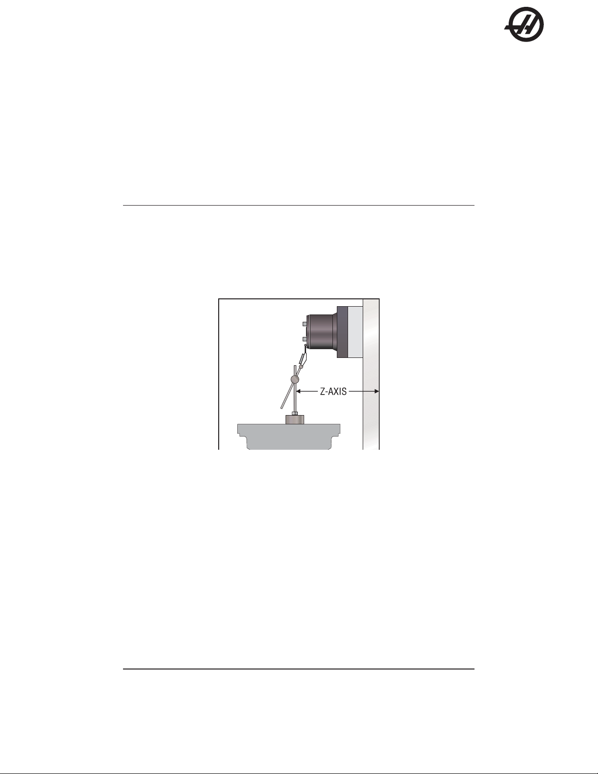
CHECKING Z-AXIS:
1. Set up a dial indicator and base on the mill table as shown in Fig. 1.3-3.
Figure 1.3-3. Dial indicator in position to check Z-axis.
2. Set dial indicator and the “Distance to go” display in the HANDLE JOG mode to zero as follows:
• Zero the dial indicator.
• Press the MDI key on the control panel.
• Press the HANDLE JOG key on the control panel.
The “Distance to go” display in the lower right hand corner of the screen should read: X=0 Y=0 Z=0
3. Set the rate of travel to .001 on the control panel and jog the machine .010 in the positive (+) Z
direction. Jog back to zero (0) on the display. The dial indicator should read zero (0) ± .0001.
4. Repeat Step 3 in the negative (-) direction.
An alternate method for checking backlash is to place the dial indicator as shown in Fig. 1.3-3 and manually
push the Z-Axis forward and back while listening for a ‘clunk’. The dial indicator should return to zero after
releasing the axis.
NOTE: The servo motors must be on to check backlash by this method.
5. If backlash is found, refer to "Backlash - Possible Causes" in this section.
96-0189 rev J
June 2004
TROUBLESHOOTING
15
Page 17

Horizontal Centers
BACKLASH - POSSIBLE CAUSES:
If backlash is found in the system, check for the following possible causes:
• Loose SHCS attaching the ball nut to the nut housing. Tighten the SHCS as described in "Mechanical
Service" section.
• Loose SHCS attaching the nut housing to the column, head, or saddle, depending on the axis. Tighten
the SHCS as described in "Mechanical Service".
• Loose clamp nut on the bearing sleeve. Tighten the SHCS on the clamp nut.
• Loose motor coupling. Tighten as described in "Mechanical Service".
• Broken or loose flex plates on the motor coupling.
• Loose SHCS attaching the bearing sleeve to the motor housing or top of column. Tighten as described
in "Ball Screw" section.
• Defective thrust bearings in the bearing sleeve. Replace the bearing sleeve as outlined in "Bearing
Sleeve" section.
• Loose SHCS attaching the axis motor to the motor housing. If the SHCS are found to be loose, inspect
the motor for damage. If none is found, tighten as described in "Axis Motor" section. If damage is found,
replace the motor.
• Incorrect backlash compensation number in Parameter 13, 27, or 41.
• Worn ball screw .
NOTE: The coupling cannot be serviced in the field and must be replaced as a unit
if it is found to be defective.
EC-400 A-Axis Backlash Adjustment (Full Forth)
1° indexer instructions are different, see the instructions at the end of this section.
1. Remove all parts and fixtures from the platter .
2. Check and record backlash near the outer edge of the platter face, using approximately
15-20 ft./lbs. The factory specification is 0.0003” to 0.0007”.
NOTE: Check backlash in each of the four quadrants (every 90°).
3. Remove the (4) 10-32 BHCS that retain the worm housing cover. Place a drip p an beneath the
black bearing housing cover to catch any gear oil (keep this pan in place for Step 4). Remove the
bearing housing cover. It may be necessary to apply channel lock pliers to the bearing housing in
order to remove it; if this is necessary , use a rag to prevent marring.
4. Note the position of the dimple located on the flange of the bearing housing. Mark this position on
an adjacent part of the casting for reference. Remove the four 5/16-18 cap screws. Do not pull the
housing out or gear oil will pour out of the housing. Put two (2) screws part way in housing holes
and turn housing with lever.
5. Index the bearing housing one set of holes. Move to the next set of holes by rotating the hole set
upwards (towards the platter) - This may be CC or CCW . Bolt the bearing housing flange down.
Torque the bolts to 25 ft./lbs. Check the backlash in each of the four quadrants. The factory
specification is 0.0003” to 0.0007”.
16
If necessary , repeat S teps 4 and 5.
6. Replace the bearing housing cover. Replace the side cover sheetmetal and reatt ach with the (4)
BHCS removed in Step 3.
TROUBLESHOOTING
96-0189 rev J
June 2004
Page 18

Horizontal Centers
7. Remove the oil filler pipe plug. If the oil level covers less than half of the sight glass, then add as
follows in step 8.
8. Refill the gear case with Mobil SHC-630 gear oil to the midpoint of the oil level eye.
9. Reinstall the oil fill pipe plug form step 7.
A-axis backlash adjustment for optional 1° indexer:
The facegear must be disengaged before checking backlash. First raise the platter by applying air to the lift
piston with Haas tool number T -2150. Disconnect the A-axis and connect tool T -2150 as shown on drawing T -
2150. Toggle air to the lift piston with the regulator set between 20 to 40 PSI [138-276 kilopascals]. Check
backlash at each quadrant (every 90°). Backlash on the 1° indexer option is .0007”-.0015” (nonstandard).
Adjust as necessary . See the previous adjustment description.
96-0189 rev J
June 2004
TROUBLESHOOTING
17
Page 19

Horizontal Centers
VIBRATION
Excessive Servo Motor Vibration
• If no “A” axis is present, swap the suspected bad servo motor with the “A” driver and check to see if
there is a driver problem. If needed, replace the DRIVER PCB ("Electrical Service").
• Check all parameters of the suspected axis against the parameters as shipped with the machine. If there
are any differences, correct them and determine how the parameters were changed. P ARAMETER LOCK
should normally be ON.
• A bad motor can cause vibration if there is an open or short in the motor . A short would normally cause
a GROUND FAUL T or OVERCURRENT alarm; check the ALARMS. An ohmmeter applied to the motor
leads should show between 1 and 3 ohms between leads, and over 1 megohm from leads to ground. If
the motor is open or shorted, replace.
OVERHEATING
Servo motor overheating
• If a motor OVERHEA T alarm occurs (ALARMS 135-138), check the parameters for an incorrect setting.
Axis flags in Parameters 1, 15, or 29 can invert the overheat switch (OVER TEMP NC).
• If the motor is actually getting hot to the touch, there is excessive load on the motor. Check the user’s
application for excessive load or high duty cycle. Check the ball screw for binding ("Accuracy/Backlash"
section). If the motor is binding by itself, replace in accordance with "Axis Motor" section.
FOLLOWING ERROR
Following Error alarms occur on one or more axes sporadically
• Check DC bus voltage on "Diagnostics" page 2. V erify this voltage on the drive cards in the control panel.
If it is at the low side of the recommended voltages, change the transformer tap to the next lower voltage
group as explained in the Installation section of the Reference manual.
• Check motor wiring for shorts.
• Replace driver card ("Electrical Service").
• Replace servo motor ("Axis Motor").
BALL S CREWS - VISUAL INSPECTION
The three main causes of Ball Screw failure are:
Loss of Lubrication
Contamination
Machine Crash
Wear of the nut balls and the screw threads is generally a non-issue under proper operating conditions.
Each type of suspect cause will leave telltale signs on the Ball Screw itself.
Loss of Lubrication:
The lubrication system of the machine provides a layer of oil for the Ball Screw components to operate on,
eliminating metal-to-metal contact. Should a problem with the lubrication system develop, that failure will
accelerate all wear issues.
18
TROUBLESHOOTING
96-0189 rev J
June 2004
Page 20

Horizontal Centers
1. Dry metal-to-metal contact following lube breakdown will create intense heat at the contact points.
The Nut balls will weld to the nut races due to the heat and pressure of the preload. When movement of the Ball Screw continues, the welds will be broken, ripping off particles of both the balls
and the races. This loss of diameter will reduce the preload, reducing machine accuracy .
Ball Screws with this type of wear, but no screw surface marring, can be rep aired by the factory .
2. A second cause of wear of the Ball Screws is material fatigue. Material fatigue typically occurs at
the end of the Ball Screw service life. Signs of material fatigue include black, contaminated
coolant, pitting of the screw surface, loss of preload, and metal flakes on the Ball Screw .
Ball Screws suffering from material fatigue are not repairable.
Contamination:
Contamination of the lubrication and/or coolant systems of the machine will produce problems with the Ball
Screws.
Check the condition of the lube on the Ball Screw threads.
1. If the lube is wet and clean, this indicates a properly functioning lube system.
2. If the lube is thick and dark, but free of metal chips, the lube itself is old and must be changed out.
The entire system should be cleaned of the old lube.
3. If the lube is wet and black, the lube system has been contaminated by metal particles. Inspect
the Ball Screws for wear.
Contamination of the lube and/or coolant systems can be caused by a wearing Ball Screw , or by metal chips
entering the systems through open or loose way covers. Check all way covers and seals for excessive clearances.
Machine Crash:
A hard machine crash can cause a Ball Screw to lock up. The static overload created during a machine crash
can break apart the ball-nut balls, denting the thread surfaces. Turning the nut by hand will result in an obvious
grinding feeling and/or sound.
1. Check the screw for straightness.
2. Look for ball dents at the ends of the screw length. These indents will be a sure sign of a hard
machine crash. The inertia of the table is transferred, due to the sudden stop, directly to the balls
inside the ball nut, creating impressions on the screw surface.
BALL SCREW CLEANING
In most cases, a thorough cleaning of the suspect Ball Screw will resolve “bad screw” issues, including noise
complaints.
1. Manually jog the ball nut to one end of the screw.
2. Visually inspect the screw threads. Look for metal flakes, dark or thick lube, or contaminated
coolant: See the “Ball Screws - Visual Inspection - Contamination” section.
96-0189 rev J
June 2004
3. Use alcohol, or other approved cleaning agents, to wash the screw.
CAUTION! Do not use detergents, degreasers, or solvents to clean Ball Screws or their
components. Do not use water-based cleaners, as they may cause rust.
TROUBLESHOOTING
19
Page 21

Horizontal Centers
4. Jog the ball nut to the other end of its travel. If metal flakes are now present on the screw threads,
5. Re-lubricate screw threads before returning the machine to service.
DRIVE FAULT / OVERCURRENT
Y-axis motor overcurrent.
• Alarm not cleared
• Check Y axis parameters
• Check the ball screw for binding
• Check motor and cable for shorts
• Check amplifier
you may have wear issues.
20
TROUBLESHOOTING
96-0189 rev J
June 2004
Page 22

Horizontal Centers
1.4 EC-400 PALLET CHANGER OVERVIEW
When the automatic pallet changer (APC) is at rest, the pallet is clamped, the pallet at the load station is at
home position, and the APC door is closed. The H-frame “Down” solenoid is on, the safety solenoid is on, and
the H-frame is down with the H-frame lock pin engaged in the bumper mount. The APC servo has been zero
returned, using the APC home sensor .
When a pallet change is commanded the following events occur in this order:
1. H-frame down switch is checked to verify down status.
2. Z-axis rapids, if necessary , to a position specified by the grid offset & p arameter 64.
3. A-axis rapids, if necessary, to position specified by grid offset & parameter 224 (this may involve a raise &
lower of the pallet).
4. The lifting and lowering of the A-axis platter is monitored by a sensor assembly located on the bottom of the
A-axis, on indexer style machines. There are no sensors monitoring the A-axis platter position on machines
with the full 4th axis option.
5. The A-axis is allowed to rotate, once the platter lif t sensor is triggered.
6. When the A-axis moves to the home position and lowered, the platter down sensor is triggered and the
platter lift sensor is turned off.
7. Power is turned on to the pallet clamp/unclamp solenoid located at the rear of the machine.
8. The clamp air pressure is released from the clamp side of the receiver piston and 100 PSI of air is applied to
the unclamp side of the receiver piston.
9. The clamp plate rises.
10. When the clamp plate moves approximately .400" it will trigger the pallet unclamp sensor . The sensor
sends a signal to the CNC control, that the clamp plate is in the unclamp position. A sensor assembly located
on the bottom of the A-axis monitors the clamp plate position.
11. APC door switch & load station lock switch are checked.
12. The H-frame down solenoid & safety solenoid turn off.
13. The H-frame up solenoid turns on.
14. Air pressure in the air cylinder rotates the top cam, by rot ating the seal housing. The bottom cam does not
rotate.
16. The cage & 3 balls rotate at half speed of the cam, forcing the cams to separate.
17. The top cam raises the H-frame by lifting upward on the hub, using the tapered bearing as a thrust bearing.
18. The H-frame engages and raises both pallets as it is raised.
19. The APC shaft does not rise. The hub slides up the shaf t on the 4 ball bearings. The flat t ang of the apc
shaft slides inside a slot in the cycloid hub.
20. The H-frame Up-switch checks H-frame up status. As the H-frame rises, the lock pin comes out of the hole
in the bumper mount, so the H-frame can rotate.
96-0189 rev J
June 2004
TROUBLESHOOTING
21
Page 23

Horizontal Centers
21. Once the H-frame up switch indicates up, the air blast solenoid is turned on, and sends air blowing thru the
air blast assembly at the top of the receiver.
22. The servomotor rotates the H-frame and pallets 180 deg., by driving through the gearbox, torque tube, &
hub, while the apc shaft, cycloid hub, and part of the gearbox remain stationary .
The servomotor rotates with the assembly .
23. The H-frame down switch gets a momentary false signal as it rot ates past the t ang on the APC shaf t
approximately mid stroke, which the software ignores.
24. The safety solenoid, which is off, prevents the H-frame from suddenly lowering in the event of a power failure
by blocking the vent port of the h frame up solenoid.
25. When it has rotated 180 degrees, the servomotor stops, and holds position. The encoder on the servomotor
determines the rotational position.
26. The H-frame up solenoid is turned off.
27. The H-frame down solenoid and safety solenoids are turned on, pressurizing the other side of the air
cylinder while venting the side previously pressurized.
28. The top cam is rotated back to its original position, allowing the H-frame and p allets to lower .
As the H-frame lowers, a lock pin under the H-frame drops into a hole in the bumper mount. It keeps the H-
frame from being moved while the servo power is off.
29. The pallet in the machine is lowered onto the receiver and the pallet on the load station is lowered onto the
index-disc pallet-pins.
30. Power is turned off to the clamp/unclamp solenoid and air blast solenoids located at the rear of the machine.
31. The unclamp air pressure is exhausted from the unclamp side of the receiver piston and air blast is turned
off while simultaneously applying 100 PSI of air pressure to the clamp side of the receiver piston.
32. The clamp plate moves down to clamp the pallet. The clamp plate will move approximately .400" and clamp
the pallet. It will trigger the pallet clamp sensor , indicating that the p allet is clamped. The clamp plate position
is monitored by a sensor assembly located on the bottom of the A axis.
33. The load station lock plate prevents the load station pallet from falling off if it is rocked severely while
loading parts.
22
TROUBLESHOOTING
96-0189 rev J
June 2004
Page 24

Horizontal Centers
1.5 AUTOMATIC TOOL CHANGER (ATC)
Refer to the alarm description when problems arise with the ATC
See “Spindle” section for additional trouble shooting information.
CRASHING
Crashing of the ATC is usually a result of operator error. The most common A TC crashes is the p art or fixture on
the mill table crashes into long tooling or into the ATC double arm during a tool change
• Inspect the pocket involved in the crash for damage and replace parts as necessary .
• The machine will normally home the Z-axis as part of the tool change sequence. Check Parameter 209
bit "TC Z NO HOME", and ensure it is set to zero.
96-0189 rev J
June 2004
TROUBLESHOOTING
23
Page 25
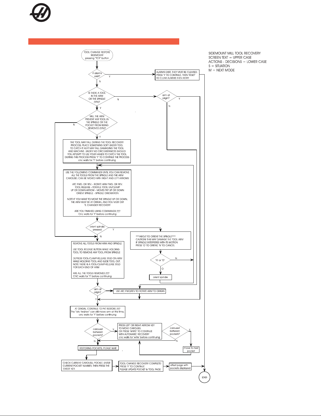
Horizontal Centers
SIDE M OUNT TOOL CHANGER RECOVERY FLOW CHART
24
TROUBLESHOOTING
96-0189 rev J
June 2004
Page 26

1.6 THROUGH THE S PINDLE COOLANT
Horizontal Centers
NOTE: Abrasive swarf from grinding or ceramic machining operations will cause
heavy wear of TSC coolant pump, coolant tip and drawbar. This is not covered
by warranty on new machines. Notify HAAS Service Department if machine is
being used for this application.
COOLANT OVERFLOW
Check the alarm history to determine the cause of the problem before any action is taken.
Coolant pouring out of spindle head
• Check the customer's tooling for through holes in the pull stud, holder and tool.
• Check the purge and drain lines connected to the seal housing are intact; if not replace.
• Check the TSC coolant union. If failure is found, replace the coolant union.
• Check pre-charge pressure in accordance with TSC "Precharge Regulator Adjustment' section and reset
if necessary . Low pre-charge pressure can cause coolant to dump into the spindle head.
• Ensure the coolant pump relief valve has not been tampered with (yellow paint band is intact). Check the
coolant pump pressure (should be 300 psi [2068 kilosascals]), with a standard (non-TSC) tool holder in
spindle. If pump pressure is above 310 psi, reset the pump relief valve.
Excessive coolant flow out of drain line or pulsating flow through tool and drain line
• Check pre-charge pressure in accordance with TSC "Precharge Regulator Adjustment" section. Reset
precharge pressure if necessary . Low pre-charge pressure will cause heavy or pulsating flow from the
drain line. Check main air pressure regulator for 85 psi [241 kilopascals]. A higher supply pressure will
reduce precharge pressure. Lower supply pressure will increase precharge pressure.
• Ensure the coolant pump relief valve has not been tampered with (yellow paint band is intact). Check
the coolant pump pressure (should be 300 psi [2068 kilosascals]), with a standard tool holder in spindle. If
pump pressure is above 310 psi [2137 kilopascals], reset the pump relief valve.
LOW COOLANT
Alarm 151, "Low Thru Spindle Coolant"
• Check coolant tank level. Check for slow coolant drainage from the machine enclosure.
• Check the filter and intake strainer for any clogging. Read filter gauges with TSC running with no tool in
spindle. Check coolant lines for any clogging or kinking. Clean or replace as needed.
• Check for overheating TSC pump motor . Three phase motors have a thermal circuit that will interrupt power
to the relay coil.
• If received at start-up, check that the breaker has not tripped and that the pump is turning. Check the
electrical continuity of cables.
• Check for pressure switch failure (refer to "T esting the Coolant Pressure Switch" section), and replace
if necessary . Check the electrical continuity of the switch cable and the control function by monitoring
the "LO CLNT" bit on the Diagnostics page (0 = pressure on, 1= pressure off). Shorting the leads should
cause the bit to switch from 1 to 0. Check this before replacing the pressure switch. Leaking switches
can give intermittent alarms.
• Check pump pressure with no tool in the spindle. If the pressure is less than 60 psi, replace the pump.
• May be generated if another machine alarm occurs during TSC operation.
96-0189 rev J
June 2004
TROUBLESHOOTING
25
Page 27

Horizontal Centers
PRE-CHARGE FAILURE
Alarm 198, "Precharge Failure"
• Check for broken or disconnected pre-charge air line, and replace if necessary .
• Check if the "Tool Clamped" limit switch is sticking; replace if necessary .
• Check the "T ool Clamped" limit switch adjustment (refer to "Tool Clamp/Unclamp Switch Adjustment").
• Check for low pre-charge pressure (refer to "Precharge Regulator Adjustment" section).
• Check pre-charge solenoid for proper operation.
• May be generated if another machine alarm occurs during TSC operation.
NOTE: This alarm only applies to the TSC system.
26
TROUBLESHOOTING
96-0189 rev J
June 2004
Page 28

1.7 ELECTRICAL TROUBLESHOOTING
Horizontal Centers
CAUTION! Before working on any electrical components, power off the machine and
wait approximately 10 minutes. This will allow the high voltage power on
the brushless amplifiers to be discharged.
ELECTRICAL ALARMS
Axis Drive Fault Alarm
• Blown amplifier - indicated by a light at bottom of amplifier when power is on. Replace amplifier .
• Amplifier or MOCON is noise sensitive. If this is the case, the alarm can be cleared and the axis
will run normally for a while.
T o check an amplifier, switch the motor leads and control cables between the amplifier and the one next to it. If
the same problem occurs with the other axis, the amplifier must be replaced. If the problem stays on the same
axis, either the MOCON or control cable. The problem could also be the axis motor itself, with leads either
shorted to each other or to ground.
• Amplifier faulting out for valid reason, such as overtemp, overvoltage, or +/-12 volt undervoltage
condition. This usually results from running a servo intensive program, or unadjusted 12 volt power
supply .
Overvoltage could occur if regen load is not coming on, but this does not usually happen. The problem could
also be the axis motor itself, with leads either shorted to each other or to ground.
Axis Overload
• The fuse function built into the MOCON has been overloaded, due to a lot of motor accel/decels, or
hitting a hard stop with the axis. This safety function protects the amplifier and motor , so find the
cause and correct it. If the current program is the cause, change the program. If the axis hits a
hard stop, the travel limits may be set wrong.
Phasing Error
• The MOCON did not receive the proper phasing information from the motors. DO NOT RESET the
machine if this alarm occurs. Power the machine down and back up. If the problem persists, it is
probably a broken wire or faulty MOCON connectors. This problem could also be related to the
Low Volt age Power Supply . Check to see if the LVPS is functioning properly.
Servo Error Too Large
• This alarms occurs when the difference between the commanded axis position and the actual
position becomes larger than the maximum that is set in the parameter .
This condition occurs when the amplifier is blown, is not receiving the commands, or the 320 volt power source
is dead. If the MOCON is not sending the correct commands to the amplifier, it is probably due to a broken
wire, or a PHASING ERROR that was generated.
Axis Z Fault or Z Channel Missing
• During a self-test, the number of encoder counts was found to be incorrect. This is usually caused
by a noisy environment, and not a bad encoder. Check all shields and grounds on the encoder
cables and the motor leads that come into the amplifiers. An alarm for one axis can be caused by
a bad grounding on the motor leads of another axis.
96-0189 rev J
June 2004
TROUBLESHOOTING
27
Page 29

Horizontal Centers
Axis Cable Fault
• During a self-test, the encoder cable signals were found to be invalid. This alarm is usually caused
Alarm 101, "MOCON Comm. Failure"
• During a self-test of communications between the MOCON and main processor , the main proces-
Alarm 157, "MOCON Watchdog Fault"
• The self-test of the MOCON has failed. Replace the MOCON.
Rotary CRC Error Alarm 261
• This alarm is normally the result of an incomplete software installation. To correct this error,
by a bad cable, or a bad connection on the motor encoder connectors. Check the cable for any
breaks, and the encoder connectors at the motor controller board. Machine noise can also cause
this alarm, although it is less common.
sor does not respond, and is suspected to be dead. This alarm is generated and the servos are
stopped. Check all ribbon cable connections, and all grounding. Machine noise can also cause
this alarm, although it is less common.
Change Setting 30 to any selection but OFF (note the original selection). Then go to parameter 43
and change one of the bits from 1 to 0 or vice versa and press WRITE (The bit must be changed
from its original value to its alternate value). Simply changing the Setting and Parameter bit from
one value to another and then back again corrects the fault, and will clear any further occurrences
of the alarm. Change the bit and Setting 30 back to their original values. Press Reset to clear the
alarms or cycle power to the machine.
SAVING THE MACHINE INFORMATION
T o review a machine’ s set-up save the parameters, settings, offsets, variables and G-code programs and alarm
history to a floppy disk. To do this, insert a blank diskette, press LISTPROG, POSIT, enter the machine's serial
number and press F2. The new file suffix will be “.HIS”.
28
TROUBLESHOOTING
96-0189 rev J
June 2004
Page 30

Horizontal Centers
2. ALARMS
Any time an alarm is present, the lower right hand corner of the screen will have a blinking "ALARM". Push
the ALARM display key to view the current alarm. All alarms are displayed with a reference number and a
complete description. If the RESET key is pressed, one alarm will be removed from the list of alarms. If
there are more than 18 alarms, only the last 18 are displayed and the RESET must be used to see the
rest. The presence of any alarm will prevent the operator from starting a program.
The ALARMS DISPLAY can be selected at any time by pressing the ALARM MESGS button. When there
are no alarms, the display will show NO ALARM. If there are any alarms, they will be listed with the most
recent alarm at the bottom of the list. The CURSOR and P AGE UP and PAGE DOWN buttons can be used
to move through a large number of alarms. The CURSOR right and left buttons can be used to turn on and
off the ALARM history display .
Note that tool changer alarms can be easily corrected by first correcting any mechanical problem, pressing
RESET until the alarms are clear , selecting ZERO RET mode, and selecting AUTO ALL AXES. Some
messages are displayed while editing to tell the operator what is wrong but these are not alarms. See the
editing topic for those errors.
The following alarm list shows the alarm numbers, the text displayed along with the alarm, and a detailed
description of the alarm, what can cause it, when it can happen, and how to correct it.
Alarm number and text: Possible causes:
101 Comm. Failure with MOCON During a self-test of communications between the MOCON PCB
and main processor, the main processor does not respond, one
of them is possibly bad. Check cable connections and boards.
102 Servos Off Indicates that the servo motors are off, the tool changer is
disabled, the coolant pump is off, and the spindle motor is
stopped. Caused by EMERGENCY STOP, motor faults, tool
changer problems, or power fail.
103 X Servo Error Too Large Too much load or speed on X-axis motor. The difference between
the motor position and the commanded position has exceeded a
parameter. The servos will be turned off and a RESET must be
done to restart. This alarm can be caused by problems with the
driver, motor, or the slide being run into the mechanical stops.
The motor may also be stalled, disconnected, or the driver failed.
104 Y Servo Error Too Large Same as alarm 103.
105 Z Servo Error Too Large Same as alarm 103.
106 A Servo Error Too Large Same as alarm 103.
107 Emergency Off EMERGENCY STOP button was pressed. After the E-STOP is
released, the RESET button must be pressed once to correct
this and clear the E-STOP alarm.
This alarm will also be generated if there is a low pressure
condition in the hydraulic counterbalance system. In this case,
the alarm will not reset until the condition has been corrected.
108 X Servo Overload Excessive load on X-axis motor. This can occur if the load on the
motor is large enough to exceed the continuous rating of the
motor. This could be period of several seconds or even minutes.
The servos will be turned off when this occurs. This can be
caused by running into the mechanical stops. It can also be
caused by anything that causes a very high load on the motors.
96-0189 rev J
June 2004
ALARMS
29
Page 31

Horizontal Centers
109 Y Servo Overload Same as alarm 108.
110 Z Servo Overload Same as alarm 108.
11 1 A Servo Overload Same as alarm 108.
112 No Interrupt Electronics fault. Call your dealer.
113 Shuttle In Fault Tool changer is not completely to right. During a tool changer
114 Shuttle Out Fault Tool changer not completely to left. During a tool change
115 Turret Rotate Fault During a tool changer operation the tool turret failed to start
operation the tool in/out shuttle failed to get to the IN position.
Parameters 62 and 63 can adjust the delays. This alarm can be
caused by anything that jams the motion of the slide or by the
presence of a tool in the pocket facing the spindle. A loss of
power to the tool changer can also cause this. Check relays K9K12, and fuse F1 on IOPCB.
operation the tool in/out shuttle failed to get to the OUT position.
Parameters 62 and 63 can adjust the time-out times. This alarm
can be caused by anything that jams the motion of the slide or by
the presence of a tool in the pocket facing the spindle. A loss of
power to the tool changer can also cause this. Check relays K9K12, and fuse F1 on IOPCB.
moving, failed to stop moving or failed to stop at the right
position. Parameters 60 and 61 can adjust the delays. This
alarm can be caused by anything that jams the rotation of the
turret. A loss of power to the tool changer can also cause this.
Check relays K9-K12, and fuse F1 on IOPCB.
116 Spindle Orientation Fault Spindle did not orient correctly. This is either a vector drive
problem or a mechanical problem on machines without a vector
drive. During a spindle orientation function, the spindle is
rotated until the lock pin drops in; but the lock pin never dropped.
Parameters 66, 70, 73, and 74 can adjust delays and spindle
orient speeds. This can be caused by a trip of circuit breaker
CB4, a lack of air pressure, or too much friction with the
orientation pin.
117 Spindle High Gear Fault Gearbox did not shift into high gear. During a change to high
gear, the spindle is rotated slowly while air pressure is used to
change gears but the high gear sensor was not detected in time.
Parameters 67, 70 and 75 can adjust the delays. Check the air
pressure, circuit breaker CB4,the circuit breaker for the air
pressure solenoids, and the spindle drive.
118 Spindle Low Gear Fault Gearbox did not shift into low gear. During a change to low gear,
the spindle is rotated slowly while air pressure is used to
change gears but the low gear sensor was not detected in time.
Parameters 67, 70 and 75 can adjust the delays. Check the air
pressure, the solenoid’s circuit breaker CB4, and the spindle
drive.
119 Over Voltage Incoming line voltage is above maximum. The spindle, tool
changer, and coolant pump will stop. If this condition persists, an
automatic shutdown will begin after the time specified by
parameter 296.
30
120 Low Air Pressure Air pressure dropped below 80 PSI for a period defined by
Parameter 76. The LOW AIR PR alarm will appear on the screen
as soon as the pressure gets low, and this alarm appears after
some time has elapsed. Check your incoming air pressure for at
least 100 PSI and ensure that the regulator is set at 85 PSI.
ALARMS
96-0189 rev J
June 2004
Page 32

Horizontal Centers
121 Low Lube or Low Pressure Way lube is low or empty or the lube pressure is too high or low.
Check tank at rear of mill and below control cabinet. Also check
connector on the side of the control cabinet. Check that the lube
lines are not blocked.
122 Regen Overheat The control is overheating. This alarm will turn off the spindle
drive, coolant pump, and tool changer. One common cause of
this overheat condition is an input line voltage too high. If this
condition persists, an automatic shutdown will begin after the
interval specified by parameter 297. It can also be caused by a
high start/stop duty cycle of spindle.
123 Spindle Drive Fault Failure of spindle drive, motor or regenerative load. This can be
caused by a shorted motor, overvoltage, overcurrent,
undervoltage, failure of drive, or shorted or open regen load.
Undervoltage and overvoltage of DC bus are also reported as
alarms 160 and 119, respectively.
124 Low Battery Memory batteries need replacing within 30 days. This alarm is
only generated at power on and indicates that the 3.3 volt Lithium
battery is below 2.5 volts. If this is not corrected within 30 days,
you may lose your stored programs, parameters, offsets, and
settings.
125 Shuttle fault Tool shuttle not initialized at power on, CYCLE START or spindle
motion command. This means that the tool shuttle was not fully
retracted to the Out position.
126 Gear Fault Transmission is out of position when a command is given to
start a program or rotate the spindle. This means that the two
speed transmission is not in either high or low gear but is
somewhere in between. Check the air pressure, the solenoid’s
circuit breaker CB4, and the spindle drive. Use the POWER UP/
RESTART button to correct the problem.
127 No Turret Mark Tool carousel motor not in position. This alarm is only generated
at power-on. The AUTO ALL AXES button will correct this but be
sure that the pocket facing the spindle afterwards does not
contain a tool.
129 M Fin Fault M-code relays were active at power on. Check the wiring to your M
code interfaces. This test is only performed at power-on.
130 Tool Unclamped The tool appeared to be unclamped during spindle orientation, a
gear change, a speed change, or TSC start-up. The alarm will
also be generated if the tool release piston is energized during
Power Up. This can be caused by a fault in the air solenoids,
relays on the I/O assembly, the drawbar assembly, or in the
wiring.
131 Tool Not Clamped When clamping or powering up the machine, the Tool Release
Piston is not HOME. This is a possible fault in the air solenoids,
relays on the IO Assembly, the drawbar assembly, or wiring.
132 Power Down Failure Machine did not turn off when an automatic power-down was
commanded. Check wiring to Power Interface card on power
supply assembly, relays on the IO assembly, and the main
contactor K1.
133 Spindle Locked Shot pin did not release. This is detected when spindle motion is
commanded. Check the solenoid that controls the air to the lock,
relay K16, the wiring to the sense switch, and the switch.
96-0189 rev J
June 2004
ALARMS
31
Page 33

Horizontal Centers
134 Tool Clamp Fault When UNCLAMPING, the tool did not release from spindle when
135 X Motor Over Heat Servo motor overheat. The temperature sensor in the motor
136 Y Motor Over Heat Same as alarm 135.
137 Z Motor Over Heat Same as alarm 135.
138 A Motor Over Heat Same as alarm 135.
139 X Motor Z Fault Encoder pulse count failure. This alarm usually indicates that the
140 Y Motor Z Fault Same as alarm 139.
141 Z Motor Z Fault Same as alarm 139.
142 A Motor Z Fault Same as alarm 139.
commanded. Check air pressure and solenoid circuit breaker
CB4. Can also be caused by misadjustment of drawbar
assembly.
indicates over 150 degrees F. This can be caused by an
extended overload of the motor such as leaving the axis at the
stops for several minutes.
encoder has been damaged and encoder position data is
unreliable. This can also be caused by loose encoder
connectors.
143 Spindle Not Locked Vector drive orientation lost or spindle shot pin not fully engaged
when a tool change operation is being performed. Check air
pressure and solenoid circuit breaker CB4. This can also be
caused by a fault in the sense switch that detects the position of
the lock pin.
144 Time-out- Call Your Dealer Time allocated for use prior to payment exceeded. Call your
dealer.
145 X Limit Switch Axis hit limit switch or switch disconnected. The stored stroke
limits should stop the slides before they hit the limit switches.
Verify the value of parameter Grid Offset and check the wiring to
the limit switch and connector P5 at the side of the main cabinet.
Can also be caused by a loose encoder shaft at the back of the
motor or coupling of motor to the screw.
146 Y Limit Switch Same as alarm 145
147 Z Limit Switch Same as alarm 145
148 A Limit Switch Normally disabled for rotary axis.
149 Spindle Turning Spindle not at zero speed for tool change. A signal from spindle
drive indicating that the spindle drive is stopped is not present
while a tool change operation is going on.
150 Z and Tool Interlocked Changer not at home and either the Z or A or B axis (or any
combination) is not at zero. If RESET, E-STOP, or POWER OFF
occurs during tool change, Z-axis motion and tool changer
motion may not be safe. Check the position of the tool changer
and remove the tool if possible. Re-initialize with the AUTO ALL
AXES button but be sure that the pocket facing the spindle
afterwards does not contain a tool.
32
ALARMS
96-0189 rev J
June 2004
Page 34

Horizontal Centers
151 Low Thru Spindle Coolant For machines with Through the Spindle Coolant only. This alarm
will shut off the coolant spigot, spindle and pump, and purge the
system. Check for low coolant tank level, any filter or intake
strainer clogging, or for any kinked or clogged coolant lines. If no
problems are found with any of these, and none of the coolant
lines are clogged or kinked, call your dealer. Verify proper pump
and machine phasing.
152 Self Test Fail Control has detected an electronics fault. All motors and
solenoids are shut down. This is most likely caused by a fault of
the processors. Call your dealer.
153 X-axis Z Ch Missing Z reference signal from encoder was not received as expected.
Likely encoder contamination or parameter error.
154 Y-axis Z Ch Missing Same as alarm 153.
155 Z-axis Z Ch Missing Same as alarm 153.
156 A-axis Z Ch Missing Same as alarm 153.
157 MOCON Watchdog Fault The self-test of the MOCON has failed. Call you dealer.
158 Video/Keyboard PCB Failure Internal circuit board problem. This could also be caused by a
short in the front panel membrane keypad. Call your dealer.
159 Keyboard Failure Keyboard shorted or button pressed at power on. A power-on test
of the membrane keypad has found a shorted button. It can also
be caused by a short in the cable from the main cabinet or by
holding a switch down during power-on.
160 Low Voltage The line voltage to control is too low. This alarm occurs when the
AC line voltage drops more than 10% below nominal.
161 X-Axis Drive Fault Current in X servo motor beyond limit. Possibly caused by a
stalled or overloaded motor. The servos are turned off. This can
be caused by running into a mechanical stop. It can also be
caused by a short in the motor or a short of one motor leads to
ground.
162 Y-Axis Drive Fault Same as alarm 161.
163 Z-Axis Drive Fault Same as alarm 161.
164 A-Axis Drive Fault Same as alarm 161.
165 X Zero Ret Margin Too Small This alarm indicates that the zero return position may not be
consistent from one zero return to the next. The encoder Z
channel signal must occur between 1/8 and 7/8 revolution of
where the home switch releases. This will not turn the servos off
but will stop the zero return operation. This alarm can occur if the
home/limit switches are moved or misadjusted.
166 Y Zero Ret Margin Too Small Same as alarm 165.
167 Z Zero Ret Margin Too Small Same as alarm 165.
168 A Zero Ret Margin Too Small Same as alarm 165.
169 Spindle Direction Fault Problem with rigid tapping hardware. The spindle started turning
in the wrong direction.
170 Phase Loss Problem with incoming line voltage. This usually indicates that
there was a transient loss of input power to the machine.
96-0189 rev J
June 2004
ALARMS
33
Page 35

Horizontal Centers
173 Spindle Ref Signal Missing The Z channel pulse from the spindle encoder is missing for
174 Tool Load Exceeded The tool load monitor option is selected and the maximum load
175 Ground Fault Detected A ground fault condition was detected in the 115V AC supply. This
176 Over Heat Shutdown An overheat condition persisted longer than the interval specified
177 Over Voltage Shutdown An overvoltage condition persisted longer than the interval
178 Divide by Zero! There are some parameters that are used as a divisor and
179 Low Pressure Transmission Oil Spindle coolant oil is low or low pressure condition in lines.
180 Pallet/Fixture Not Clamped The Pallet/Fixture clamped input indicates that the pallet or fixture
hard tapping synchronization.
for a tool was exceeded in a feed. This alarm can only occur if the
tool load monitor function is installed in your machine.
can be caused by a short to ground in any of the servo motors,
the tool change motors, the fans, or the oil pump.
by parameter 296 and caused an automatic shutdown.
specified by parameter 296 and caused an automatic shutdown.
therefore must never be set to zero. If the problem cannot be
corrected by parameters, cycle power on the machine. If the
alarm reoccurs, call your dealer and report the sequence of
events that lead to the alarm.
is not clamped and it is unsafe to run the spindle. This could
also indicate that a previous pallet change was not completed
and the pallet changer needs to be recovered.
182 X Cable Fault Cable from X-axis encoder does not have valid differential
signals.
183 Y Cable Fault Same as alarm 182.
184 Z Cable Fault Same as alarm 182.
185 A Cable Fault Same as alarm 182.
186 Spindle Not Turning Status from spindle drive indicates it is not at speed when
expected.
187 B or TT Servo Error Too Large Too much load or speed on B or TT axis motor. The difference
between the motor position and the commanded position has
exceeded a parameter. The motor may also be stalled,
disconnected, or the driver failed. The servos will be turned off
and a RESET must be done to restart. This alarm can be caused
by problems with the driver, motor, or the slide being run into the
mechanical stops. On machines with servo based tool changer
chains the chain was unable to move. On machines with servo
based tool changer arms the arm was unable to move possibly
due to a stuck tool.
188 B Servo Overload Same as alarm 108.
189 B Motor Overheat Same as alarm 135.
190 B Motor Z Fault Same as alarm 139
34
191 B Limit Switch Same as alarm 148.
192 B Axis Z Ch Missing Z reference signal from encoder was not received as expected.
Likely encoder contamination or parameter error.
ALARMS
96-0189 rev J
June 2004
Page 36

Horizontal Centers
193 B Axis Drive Fault Same as alarm 161.
194 B Zero Ret Margin Too Small Same as alarm 165
195 B Cable Fault Same as alarm 182.
196 Coolant Spigot Failure Vertical mills only. Spigot failed to achieve commanded location
after two (2) attempts.
197 100 Hours Unpaid Bill Call your dealer.
198 Precharge Failure During TSC operation, the precharge failed for greater than 0.1
seconds. It will shut off the feed, spindle and pump all at once. If
received, check all air lines and the air supply pressure.
199 Negative RPM A negative spindle RPM was sensed.
201 Parameter CRC Error Parameters lost. Check for a low battery and low battery alarm.
202 Setting CRC Error Settings lost. Check for a low battery and low battery alarm.
203 Ball Screw CRC Error Ball screw compensation tables lost. Check for low battery and
low battery alarm.
204 Offset CRC Error Offsets lost. Check for a low battery and low battery alarm.
205 Programs CRC Error Users program lost. Check for a low battery and low battery
alarm.
206 Internal Program Error Possible corrupted program. Save all programs to floppy disk,
delete all, then reload. Check for a low battery and low battery
alarm.
207 Queue Advance Error Cycle power on the machine. If the alarm reoccurs, call your
dealer and report the sequence of events that lead to the alarm.
208 Queue Allocation Error Same as alarm 207
209 Queue Cutter Comp Error Same as alarm 207
210 Insufficient Memory Not enough memory to store users program. Check the space
available in the LIST PROG mode and possibly create space by
moving programs from the control and saving them to a disk.
211 Odd Prog Block Possible corrupted program. Save all programs to floppy disk,
delete all, then reload.
212 Program Integrity Error Possible corrupted program. Save all programs to floppy disk,
delete all, then reload. Check for a low battery and low battery
alarm.
213 Program RAM CRC Error Electronics fault; possibly with main processor.
214 No. of Programs Changed Indicates that the number of programs disagrees with the
internal variable that keeps count of the loaded programs.
Possible processor board problem.
215 Free Memory PTR Changed Indicates the amount of memory used by the programs counted
in the changed system disagrees with the variable that points to
free memory. Possible processor board problem.
216 EPROM Speed Failure Possible processor board problem.
96-0189 rev J
June 2004
ALARMS
35
Page 37

Horizontal Centers
217 X Axis Phasing Error Error occurred in phasing initialization of motor. This can be
218 Y Axis Phasing Error Same as alarm 217.
219 Z Axis Phasing Error Same as alarm 217.
220 A Axis Phasing Error Same as alarm 217.
221 B Axis Phasing Error Same as alarm 217.
222 C Axis Phasing Error Same as alarm 217.
223 Door Lock Failure In machines equipped with safety interlocks, this alarm occurs
224 X Transition Fault Illegal transition of encoder count pulses in X axis. This alarm
225 Y Transition Fault Same as alarm 224.
226 Z Transition Fault Same as alarm 224.
227 A Transition Fault Same as alarm 224.
caused by a bad encoder, or a cabling error.
when the control senses the door is open but it is locked. Check
the door lock circuit.
usually indicates that the encoder has been damaged and
encoder position data is unreliable. This can also be caused by
loose connectors at the MOCON or MOTIF PCB.
228 B Transition Fault Same as alarm 224.
229 C Transition Fault Same as alarm 224.
231 Jog Handle Transition Fault Illegal transition of encoder count pulses in jog handle encoder.
This alarm usually indicates that the encoder has been
damaged and encoder position data is unreliable. This can also
be caused by loose connectors.
232 Spindle Transition Fault Illegal transition of encoder count pulses in spindle encoder.
This alarm usually indicates that the encoder has been
damaged and encoder position data is unreliable. This can also
be caused by loose connectors at the MOCON.
233 Jog Handle Cable Fault Cable from jog handle encoder does not have valid differential
signals.
234 Spindle Enc. Cable Fault Cable from spindle encoder does not have valid differential
signals.
235 Spindle Z Fault Same as alarm 139.
236 Spindle Motor Overload The spindle motor is overloaded.
237 Spindle Following Error The error between the commanded spindle speed and the
actual speed has exceeded the maximum allowable (as set in
Parameter 184).
36
238 Automatic Door Fault The automatic door was commanded to operate, but did not
complete the operation. The door was: 1) Commanded to close
but failed to contact the closed switch in the time allowed, 2)
Commanded to open but failed to contact the opened switch (not
all doors have an opened switch) in the time allowed, or 3)
Commanded to open but did not begin moving in the time
allowed. Check the door switch, the door for mechanical
binding, and that the door motor and clutch are functioning
correctly.
ALARMS
96-0189 rev J
June 2004
Page 38

Horizontal Centers
239 Unknown Mocon Alarm Mocon has reported an alarm to the current software. The current
version of software was unable to identify the alarm. See mocon
software release notes for additional diagnostics.
240 Empty Prog or No EOB DNC program not found, or no end of program found.
241 Invalid Code RS-232 load bad. Data was stored as comment. Check the
program being received.
242 No End Check input file for a number that has too many digits
243 Bad Number Data entered is not a number.
244 Missing ) Comment must end with a " ) ".
245 Unknown Code Check input line or data from RS-232. This alarm can occur
while editing data into a program or loading from RS-232. See
MESSAGE PAGE for input line.
246 String Too Long Input line is too long. The data entry line must be shortened.
247 Cursor Data Base Error Cycle power on the machine. If the alarm reoccurs, call your
dealer and report the sequence of events that lead to the alarm.
248 Number Range Error Number entry is out of range.
249 Prog Data Begins Odd Possible corrupted program. Save all programs to floppy disk,
delete all, then reload.
250 Program Data Error Same as alarm 249.
251 Prog Data Struct Error Same as alarm 249.
252 Memory Overflow Same as alarm 249.
253 Electronics Overheat The control box temperature has exceeded 135 degrees F. This
can be caused by an electronics problem, high ambient
temperature, or clogged air filter.
254 Spindle Overheat The motor driving the spindle is too hot. The spindle motor
temperature sensor sensed a high temperature for greater than
1.5 seconds.
255 No Tool In Spindle There is an invalid tool number in the spindle entry of the
POCKET-TOOL table. The spindle entry cannot be 0 and must
be listed in the body of the table. If there is no tool in the spindle,
enter the number for an empty pocket into the spindle entry. If
there is a tool number in the spindle entry, make sure that it is in
the body of the table and that the pocket is empty.
256 Current Tool Unknown Current tool information has been lost. This is most likely due to
re-initialization. It is likely that the next commanded tool change
will result in a collision between the spindle and a tool in a
pocket. To eliminate the possibility of a crash, perform Tool
Changer Restore. Do not use Power Up/Restart as this will
cause the machine to try to return a tool to the carousel.
257 Program Data Error Possible corrupted program. Save all programs to floppy disk,
delete all, then reload. Possible processor board problem.
258 Invalid DPRNT Format Macro DPRNT statement not structured properly.
259 Language Version Problem with language files. Please reload foreign language
files.
96-0189 rev J
June 2004
ALARMS
37
Page 39

Horizontal Centers
260 Language CRC Indicates FLASH memory has been corrupted or damaged.
261 Rotary CRC Error Rotary table saved parameters (used by Settings 30, 78) had a
262 Parameter CRC Missing RS-232 or disk read of parameter did not have a cyclic
263 Ball Screw CRC Missing Ball screw compensation tables did not have a cyclic redundancy
264 Rotary CRC Missing Rotary table parameters did not have cyclic redundancy check
265 Macro Variable File CRC Error Macro variable file has a cyclic redundancy check (CRC) error.
266 Tool Changer Fault The tool changer did not return to the proper starting position.
267 Tool Door Out of Position Horizontal mills only. Alarm will be generated during a tool
Please reload foreign language files.
cyclic redundancy check (CRC) error. Indicates a loss of memory,
possible processor board problem.
redundancy check (CRC) when loading from disk or RS-232.
check (CRC) when loading from disk or RS-232.
(CRC) when loading from disk or RS-232
Indicates a loss of memory. Possible processor board problem.
Run Toolchanger Recovery.
change when parameter 278 TC DR SWITCH is set to 1, and the
tool carousel air door and the tool carousel air door switch
indicates that the door is open after commanded to be closed, or
closed after it was commanded to be open. This alarm will most
likely be caused by a stuck or broken switch.
268 Door open @ M95 Start Generated whenever an M95 (Sleep Mode) is encountered and
the door is open. The door must be closed in order to start sleep
mode
269 TOOL ARM FAULT The toolchanger arm is not in position. Run Toolchanger
Recovery.
270 C Servo Error Too Large Same as alarm 103.
271 C Servo Overload Same as alarm 108.
272 C Motor Overheat Same as alarm 135.
273 C Motor Z Fault Same as alarm 139.
274 C Limit Switch Axis hit limit switch or switch disconnected. The stored stroke
limits should stop the slides before they hit the limit switches.
Verify the value of parameter Grid Offset and check the wiring to
the limit switch and connector P5 at the side of the main cabinet.
Can also be caused by a loose encoder shaft at the back of the
motor or coupling of motor to the screw.
275 C Axis Z Ch Missing Same as alarm 153.
276 C Axis Drive Fault Same as alarm 161.
277 C Zero Ret Margin Too Small Same as alarm 165.
38
278 C Cable Fault Same as alarm 182.
279 X Axis Linear Scale Z Fault Encoder marker pulse count failure. This alarm usually indicates
that the Z Fault encoder has been damaged and encoder
position data is unreliable. This can also be caused by loose
scale connectors.
280 Y Axis Linear Scale Z Fault Same as alarm 279.
ALARMS
96-0189 rev J
June 2004
Page 40

Horizontal Centers
281 Z Axis Linear Scale Z Fault Same as alarm 279.
282 A Axis Linear Scale Z Fault Same as alarm 279.
283 X Axis Linear Scale Z CH Missing Broken wires or encoder contamination. All servos are turned off.
This Z Channel Missing can also be caused by loose scale
connectors.
284 Y Axis Linear Scale Z CH Missing Same as alarm 279.
285 Z Axis Linear Scale Z CH Missing Same as alarm 279.
286 A Axis Linear Scale Z CH Missing Same as alarm 279.
287 X Axis Linear Scale Cable Fault Cable from X-axis scale does not have valid differential signals.
288 Y Axis Linear Scale Cable Fault Cable from Y-axis scale does not have valid differential signals.
289 Z Axis Linear Scale Cable Fault Cable from Z-axis scale does not have valid differential signals.
290 A Axis Linear Scale Cable Fault Cable from A-axis scale does not have valid differential signals.
291 Low Air Volume/Pressure During ATC An automatic tool change was not completed due to insufficient
volume or pressure of compressed air. Check air supply line.
292 320V Power Supply Fault Incomming line voltage is above maximum. The servo will be
turned off and the spindle, tool changer, and coolant pump will
stop. If this persists, an automatic shutdown will begin after the
interval specified by parameter 296.
293 Invalid Chamfer or Corner Rounding Distance in G01
This alarm supports the corner rounding and chamfering feature.
294 No End Move for G01 Chamfer Corner Rounding
This alarm supports the corner rounding and chamfering feature.
A chamfer or corner rounding move was requested in a G01
command, but no end move was commanded.
29 5 Move Angle Too Small in G01 Corner rounding
This alarm supports the corner rounding and chamfering feature.
Tangent of half angle is zero. Move Angle must be greater than 1
deg.
296 Invalid Plane Selection in G01 Chamfer or Corner Rounding
This alarm supports the corner rounding and chamfering feature.
Chamfer or corner rounding move and end move must be in the
same plane as the begining move.
297 ATC Shuttle Overshoot The ATC shuttle has failed to stop within the standby position
window during a tool change. Check for a loose drive belt,
damaged or over heated motor, sticking or damaged shuttle
standby switch or shuttle mark switch, or burned ATC control
board relay contacts. Use tool changer restore to recover the
ATC, then resume normal operation.
298 ATC Double Arm Out of Position The ATC double arm mark switch, CW position switch or CCW
position switch is in an incorrect state. Check for sticking,
misaligned or damaged switches, mechanism binding,
damaged motor, or debris build up. Use tool changer restore to
recover the ATC, then resume normal operation.
299 ATC Shuttle Out of Position The ATC shuttle mark switch is in an incorrect state. Check for a
sticking, misaligned, or damaged switch, mechanism binding,
damaged motor, or debris build up. Use tool changer restore to
recover the ATC, then resume normal operation.
96-0189 rev J
June 2004
ALARMS
39
Page 41

Horizontal Centers
302 Invalid R In G02 or G03 Check your geometry. R must be greater than or equal to half the
303 Invalid X, Y, or Z In G02 or G03 Check your geometry.
304 Invalid I, J, Or K In G02 Or G03 Check your geometry. Radius at start must match radius at end
305 Invalid Q In Canned Cycle Q in a canned cycle must be greater than zero.
306 Invalid I, J, K, or Q In Canned Cycle I, J, K, and Q in a canned cycle must be greater than zero.
307 Subroutine Nesting Too Deep Subprogram nesting is limited to nine levels. Simplify your
309 Exceeded Max Feed Rate Use a lower feed rate.
310 Invalid G Code G code not defined and is not a macro call.
311 Unknown Code Program contained a line of code that is not understood.
312 Program End End of subroutine reached before M99. Need an M99 to return
313 No P Code In M97, M98, or G65 In M97, M98 or G65 a subprogram number must be put in the P
distance from start to end within an accuracy of 0.0010 inches.
of arc within 0.001 inches (0.01 mm).
program.
from subroutine.
code. G47 must have P0 for text engraving or P1 for sequential
serial numbers.
314 Subprogram or Macro Not In Memory Check that a subroutine is in memory or that a macro is defined.
315 Invalid P Code In M97, M98 or M99 The P code must be the name of a program stored in memory
without a decimal point for M98 and must be a valid N number for
M99. G47 must have P0 for text engraving or P1 for sequential
serial numbers.
316 X Over Travel Range Commanded X-axis move would exceed the allowed machine
range. Machine coordinates are in the negative direction. This
condition indicates either an error in the user’s program or
improper offsets.
317 Y Over Travel Range Same as alarm 316.
318 Z Over Travel Range Same as alarm 316.
319 A Over Travel Range Commanded A-axis move would exceed the allowed machine
range. Machine coordinates are in the negative direction. This
condition indicates either an error in the user’s program or
improper offsets.
320 No Feed Rate Specified Must have a valid F code for interpolation functions.
321 Auto Off Alarm Occurs in debug mode only.
322 Sub Prog Without M99 Add an M99 code to the end of program called as a subroutine.
324 Delay Time Range Error P code in G04 is greater than or equal to 1000 seconds (over
999999 milliseconds).
40
325 Queue Full Cycle power on the machine. If the alarm reoccurs, call your
dealer and report the sequence of events that lead to the alarm.
326 G04 Without P Code Put a Pn.n for seconds or a Pn for milliseconds.
327 No Loop For M Code Except M97, M98 L code not used here. Remove L Code.
ALARMS
96-0189 rev J
June 2004
Page 42

Horizontal Centers
328 Invalid Tool Number Tool number must be between 1 and the value in Parameter 65.
329 Undefined M Code That M code is not defined and is not a macro call.
330 Undefined Macro Call Macro name O90nn not in memory. A macro call definition is in
parameters and was accessed by user program but that macro
was not loaded into memory.
331 Range Error Number too large.
332 H and T Not Matched This alarm is generated when Setting 15 is turned ON and an H
code number in a running program does not match the tool
number in the spindle. Correct the Hn codes, select the right tool,
or turn off Setting 15.
333 X-Axis Disabled Parameter has disabled the axis.
334 Y-Axis Disabled Parameter has disabled the axis.
335 Z-Axis Disabled Parameter has disabled the axis.
336 A-Axis Disabled An attempt was made to program the A-axis while it was
disabled (DISABLED bit in Parameter 43 set to 1) or invisible
(INVIS AXIS bit in Parameter 43 set to 1).
337 GOTO or P line Not Found Subprogram is not in memory, or P code is incorrect, or a P value
is not found
338 Invalid IJK and XYZ in G02 or G03 There is a problem with circle definition; check your geometry.
339 Multiple Codes Only one M, X, Y, Z, A, Q etc. allowed in any block, or only one G
code in the same group.
340 Cutter Comp Begin With G02 or G03 Select cutter compensation earlier. Cutter comp. must begin on
a linear move.
341 Cutter Comp End With G02 or G03 Disable cutter comp later.
342 Cutter Comp Path Too Small Geometry not possible. Check your geometry.
343 Display Queue Record Full Cycle power on the machine. If the alarm reoccurs, call your
dealer and report the sequence of events that lead to the alarm.
344 Cutter Comp With G18 and G19 Cutter comp only allowed in XY plane (G17).
346 Illegal M Code There was an M80 or M81 commanded. These commands are
not allowed while Setting 51 DOOR HOLD OVERRIDE is OFF.
Also check Setting 131 for Auto Door and Parameter 57 for
DOOR STOP SP. B. There was an M17 or M18 commanded in
program restart. These commands are illegal in program restart.
347 Invalid or Missing E Code All 5-axis canned cycles require the depth to be specified using a
positive E code.
348 Motion Not Allowed In G93 Mode This alarm is generated if the mill is in Inverse Time Feed mode,
and a G12, G13, G70, G71, G72, G150, or any Group 9 motion
command is issued.
349 Prog Stop W/O Cancel Cutter Comp An X/Y cutter compensation exit move is required before a
program stop.
350 Cutter Comp Look Ahead Error There are too many non-movement blocks between motions
when cutter comp is being used. Remove some intervening
blocks.
96-0189 rev J
June 2004
ALARMS
41
Page 43

Horizontal Centers
351 Invalid P Code In a block with G103 (Block Lookahead Limit), a value between 0
352 Aux Axis Power Off Aux C, U, V, or W axis indicate servo off. Check auxiliary axes.
353 Aux Axis No Home A ZERO RET has not been done yet on the aux axes. Check
354 Aux Axis Disconnected Aux axes not responding. Check auxiliary axes and RS-232
355 Aux Axis Position Mismatch between machine and aux axes position. Check aux
356 Aux Axis Travel Limit Aux axes are attempting to travel past their limits.
357 Aux Axis Disabled Aux axes are disabled.
358 Multiple Aux Axis Can only move one auxiliary axis at a time.
359 Invalid I, J, or K In G12 or G13 Check your geometry.
360 Tool Changer Disabled Check Parameter 57. Not a normal condition for VF Series Mills.
361 Gear Change Disabled Check Parameter 57. Not a normal condition for VF Series Mills.
and 15 must be used for the P code.
Status from control was OFF.
auxiliary axes. Status from control was LOST.
connections.
axes and Mismatch interfaces. Make sure no manual inputs
occur to aux axes.
362 Tool Usage Alarm RESET. Tool life limit was reached. To continue, reset the usage count in
the Current Commands display and press
363 Coolant Locked Off Override is off and program tried to turn on coolant.
364 No Circ Interp Aux Axis Only rapid or feed is allowed with aux axes.
365 P Definition Error P value not defined, or P value out of range. An M59 or M69 must
have a P value between the range of 1100 and 1155.
366 Missing I, K OR L IN G70, G71 OR G72 Checks for missing values.
367 Cutter Comp Interference G01 cannot be done with tool size.
368 Groove Too Small Tool too big to enter cut.
369 Tool Too Big Use a smaller tool for cut.
370 Pocket Definition Error Check geometry for G150.
371 Invalid I, J, K, OR Q Check G150.
372 Tool Change In Canned Cycle Tool change not allowed while canned cycle is active.
373 Invalid Code in DNC A code found in a DNC program could not be interpreted
because of DNC restrictions.
374 Missing XYZA in G31 or G36 G31 skip function requires an X, Y, Z, or A move.
42
375 Missing Z or H in G37 G37 automatic tool length measurement function requires H
code, Z value, and tool offset enabled. X, Y, and A values not
allowed.
376 No Cutter Comp In Skip Skip G31 and G37 functions cannot be used with cutter
compensation.
377 No Skip in Graph/Sim Graphics mode cannot simulate skip function.
ALARMS
96-0189 rev J
June 2004
Page 44

Horizontal Centers
378 Skip Signal Found Skip signal check code was included but skip was found when it
was not expected.
379 Skip Signal Not Found Skip signal check code was included but skip was not found
when it was expected.
380 X, Y, A, or G49 Not Allowed in G37 G37 may only specify Z-axis and must have tool offset defined.
38 1 G43 or G44 Not Allowed in G36 or G136 Auto work offset probing must be done without tool offset.
382 D Code Required in G35 A Dnnn code is required in G35 in order to store the measured
tool diameter.
383 Inch Is Not Selected G20 was specified but settings have selected metric input.
384 Metric Is Not Selected G21 was specified but settings have selected inches.
385 Invalid L, P, or R G10 was used to change offsets but L, P, or R code is missing or
Code In G10 invalid.
386 Invalid Address Format An address A...Z was used improperly.
387 Cutter Comp Not Allowed With G103 If block buffering has been limited, Cutter comp cannot be used.
388 Cutter Comp Not Allowed With G10 Coordinates cannot be altered while cutter comp is active.
Move G10 outside of cutter comp enablement.
389 G17, G18, G19 Illegal in G68 Planes of rotation cannot be changed while rotation is enabled.
390 No Spindle Speed S code has not been encountered. Add an S code.
391 Feature Disabled An attempt was made to use a control feature not enabled by a
parameter bit. Set the parameter bit to 1.
392 B Axis Disabled An attempt was made to program the B-axis while it was
disabled (DISABLED bit in Parameter 151 set to 1) or invisible
(INVIS AXIS bit in Parameter 151 set to 1).
393 Invalid Motion In G74 or G84 Rigid Tapping can only be in the Z minus G74 or G84 direction.
Make sure that the distance from the initial position to the
commanded Z depth is in the minus direction.
394 B Over Travel Range Same as alarm 316.
395 No G107 Rotary Axis A rotary axis must be specified in order to perform cylindrical
mapping Specified (G107).
396 Invalid G107 Rotary Axis Specified The rotary axis specified is not a valid axis, or has been disabled.
397 Aux Axis In G93 Block This alarm is generated if a G-code block specifies any form of
interpolated motion that involves BOTH one or more of the
regular axes (X, Y, Z, A, B, etc...) AND one or more of the auxiliary
axes (C, U, V , W).
398 Aux Axis Servo Off Aux. axis servo shut off due to a fault.
400 Skip Signal During Restart A skip signal G-code (G31, G35, G36, G37, G136) was found
during program restart.
403 RS-232 Too Many Progs Cannot have more than 200 programs in memory.
404 RS-232 No Program Name Need name in programs when receiving ALL; otherwise has no
way to store them.
96-0189 rev J
June 2004
ALARMS
43
Page 45

Horizontal Centers
405 RS-232 Illegal Prog Name Check files being loaded. Program name must be Onnnnn and
406 RS-232 Missing Code A receive found bad data. Check your program. The program will
407 RS-232 Invalid Code Check your program. The program will be stored but the bad
408 RS-232 Number Range Error Check your program. The program will be stored but the bad
409 RS-232 Invalid N Code Bad Parameter or Setting data. User was loading settings or
410 RS-232 Invalid V Code Bad parameter or setting data. User was loading settings or
411 RS-232 Empty Program Check your program. Between % and % there was no program
412 RS-232 Unexpected End of Input Check Your Program. An ASCII EOF code was found in the input
413 RS-232 Load Insufficient Memory Program received does not fit. Check the space available in the
must be at beginning of a block.
be stored but the bad data is turned into a comment.
data is turned into a comment.
data is turned into a comment.
parameters and something was wrong with the data.
parameters and something was wrong with the data.
found.
data before program receive was complete. This is a decimal
code 26.
LIST PROG mode and possibly delete some programs.
414 RS-232 Buffer Overflow Data sent too fast to CNC. Computer sending data may not
respond to X-OFF
415 RS-232 Overrun Data sent too fast to CNC.
416 RS-232 Parity Error Data received by CNC has bad parity. Check parity settings,
number of data bits and speed. Also check your wiring.
417 RS-232 Framing Error Data received was garbled and proper framing bits were not
found. One or more characters of the data will be lost. Check
parity settings, number of data bits and speed.
418 RS-232 Break Break condition while receiving. The sending device set the line
to a break condition. This might also be caused by a simple
break in the cable.
419 Invalid Function For DNC A code found on input of a DNC program could not be
interpreted.
420 Program Number Mismatch The O code in the program being loaded did not match the O
code entered at the keyboard. Warning only.
421 No Valid Pockets Pocket Table is full of dashes.
422 Pocket Table Error If the machine is equipped with a 50 taper spindle there must be
2 dashes between L’s (large tools). L’s must be surrounded by
dashes.
44
429 Disk Dir Insufficient Memory Disk memory was almost full when an attempt was made to
read the disk directory.
430 Disk Unexpected End of Input Check your program. An ASCII EOF code was found in the input
data before program receive was complete. This is a decimal
code 26.
431 Disk No Prog Name Need name in programs when receiving ALL; otherwise has no
way to store them.
ALARMS
96-0189 rev J
June 2004
Page 46

Horizontal Centers
432 Disk Illegal Prog Name Check files being loaded. Program must be Onnnnn and must
be at the beginning of a block.
433 Disk Empty Prog Name Check your program. Between % and % there was no program
found.
434 Disk Load Insufficient Memory Program received does not fit. Check the space available in the
LIST PROG mode and possibly delete some programs.
435 Disk Abort Could not read disk.
436 Disk File Not Found Could not find disk file.
501 Too Many Assignments In One Block Only one assignment macro assignment is allowed per block.
Divide block into multiple blocks.
502 [ Or = Not First Term In Expressn An expression element was found where it was not preceded by
“[“ or “=”, that start expressions.
503 Illegal Macro Variable Reference A macro variable number was used that is not supported by this
control, use another variable.
504 Unbalanced Brackets In Expression Unbalanced brackets, “[“ or “]”, were found in an expression. Add
or delete a bracket.
505 Value Stack Error The macro expression value stack pointer is in error. Cycle
power on the machine. If the alarm reoccurs, call your dealer and
report the sequence of events that lead to the alarm.
506 Operand Stack Error The macro expression operand stack pointer is in error. Cycle
power on the machine. If the alarm reoccurs, call your dealer and
report the sequence of events that lead to the alarm.
507 Too Few Operands On Stack An expression operand found too few operands on the
expression stack. Cycle power on the machine. If the alarm
reoccurs, call your dealer and report the sequence of events that
lead to the alarm.
508 Division By Zero A division in a macro expression attempted to divide by zero. Re-
configure expression.
509 Illegal Macro Variable Use See "MACROS" section for valid variables.
510 Illegal Operator or Function Use See “MACROS” section for valid operators.
511 Unbalanced Right Brackets Number of right brackets not equal to the number of left brackets.
512 Illegal Assignment Use Attempted to write to a read-only macro variable.
513 Var. Ref. Not Allowed With N Or O Alphabetic addresses N and O cannot be combined with macro
variables. Do not declare N#1, etc.
514 Illegal Macro Address Reference A macro variable was used incorrectly with an alpha address.
Same as 513.
515 Too Many Conditionals In a Block Only one conditional expression is allowed in any WHILE or IF-
THEN block.
516 Illegal Conditional Or No Then A conditional expression was found outside of an IF-THEN,
WHILE, or M99 block.
517 Exprsn. Not Allowed With N Or O A macro expression cannot be linked to N or O. Do not declare
O[#1], etc.
96-0189 rev J
June 2004
ALARMS
45
Page 47

Horizontal Centers
518 Illegal Macro Exprsn Reference An alpha address with expression, such as A[#1+#2], evaluated
519 Term Expected In the evaluation of a macro expression, an operand was
520 Operator Expected In the evaluation of a macro expression an operator was
521 Illegal Functional Parameter An illegal value was passed to a function, such as SQRT[ or
522 Illegal Assignment Var Or Value A variable was referenced for writing. The variable referenced is
523 Conditional Reqd Prior To THEN THEN was encountered and a conditional statement was not
524 END Found With No Matching DO An END was encountered without encountering a previous
525 Var. Ref. Illegal During Movement Variable cannot be read during axis movement.
526 Command Found On DO/END Line A G-code command was found on a WHILE-DO or END macro
527 = Not Expected Or THEN Required Only one Assignment is allowed per block, or a THEN statement
incorrectly. Same as 517.
expected and not found.
expected and not found.
ASIN[.
read only.
processed in the same block.
matching DO. DO-END numbers must agree.
block. Move the G-code to a separate block.
is missing.
528 Parameter Precedes G65 On G65 lines all parameters must follow the G65 G-code. Place
parameters after G65.
529 Illegal G65 Parameter The addresses G, L, N, O, and P cannot be used to pass
parameters.
530 Too Many I, J, or K’s In G65 Only 10 occurrences of I, J, or K can occur in a G65 subroutine
call. Reduce the I, J, or K count.
531 Macro Nesting Too Deep Only four levels of macro nesting can occur. Reduce the amount
of nested G65 calls.
532 Unknown Code In Pocket Pattern Macro syntax is not allowed in a pocket pattern subroutine.
533 Macro Variable Undefined A conditional expression evaluated to an UNDEFINED value, i.e.
#0. Return True or False.
534 DO Or END Already In Use Multiple use of a DO that has not been closed by and END in the
same subroutine. Use another DO number.
535 Illegal DPRNT Statement A DPRNT statement has been formatted improperly, or DPRNT
does not begin block.
536 Command Found On DPRNT Line A G-code was included on a DPRNT block. Make two separate
blocks.
537 RS-232 Abort On DPRNT While a DPRNT statement was executing, the RS-232
communications failed.
46
538 Matching END Not Found A WHILE-DO statement does not contain a matching END
statement. Add the proper END statement.
539 Illegal Goto Expression after GOTO not valid.
540 Macro Syntax Not Allowed A section of code was interpreted by the control where macro
syntax is not permitted.
ALARMS
96-0189 rev J
June 2004
Page 48

Horizontal Centers
541 Macro Alarm This alarm was generated by a macro command in a program.
600 U Over Travel Range Same as alarm 316.
601 V Over Travel Range Same as alarm 316.
602 W Over Travel Range Same as alarm 316.
603 U Limit Switch Same as alarm 145.
604 V Limit Switch Same as alarm 145.
605 W Limit Switch Same as alarm 145.
609 U Servo Error Too Large Same as alarm 103.
610 V Servo Error Too Large Same as alarm 103.
611 W Servo Error Too Large Same as alarm 103.
612 U Servo Overload Same as alarm 108.
613 Command Not Allowed In Cutter Comp. At least one command in the highlighted block cannot be
executed while cutter compensation is active. M codes such as
M06, M46, M50 and M96 are not allowed. Your program must
have a G40 and a cutter comp. exit move before the M code.
614 V Servo Overload Same as alarm 108.
615 W Servo Overload Same as alarm 108.
616 U Motor Over Heat Same as alarm 135.
617 V Motor Over Heat Same as alarm 135.
618 W Motor Over Heat Same as alarm 135.
619 U Motor Z Fault Same as alarm 139.
620 C Axis Disabled Parameters have disabled this axis
621 C Over Travel Range C-axis will exceed stored limits. This is a parameter in negative
direction and is machine zero in the positive direction. This will
only occur during the operation of a user's program.
The following alarms apply only to the Vertical Mills with a sidemount tool changer:
622 Tool Arm Fault This alarm supports the side mount tool changers. It is
generated if the arm is not at the Origin position, or the arm
motor is already on when a tool change process is started.
625 Carousel Positioning Eror This alarm is generated by a side mount tool changer if
conditions are not correct when:
• The carousel or tool arm was started and one or more of the
following incorrect conditions existed:
The carousel or arm motor already on, arm not at Origin, tool
carousel not at TC mark.
• The tool carousel was in motion and Tool One Mark was
detected but the current pocket facing the spindle was not at
pocket one, or the current pocket was at pocket one but Tool One
Mark was not detected.
96-0189 rev J
June 2004
ALARMS
47
Page 49

Horizontal Centers
626 Tool Pocket Slide Error This alarm is generated by a side mount tool changer. It is
627 ATC Arm Position Timeout This alarm supports the side mount tool changers. It is
628 ATC ARM Positioning Error This alarm supports the side mount tool changers. It is
630 Apc-door Sw Fault-switch Not Equal To Solenoid
generated if the tool pocket has not moved to its commanded
position (and settled) within the total time allowed by parameters
306 and 62.
generated if the tool arm has not moved after the allowed time or
has not stopped after the allowed time. Refer to Parameter 309
MOTOR COAST TIME.
generated if:
• The arm was being moved from the ORIGIN position to the
CLAMP position and it coasted past the MOTOR STOP point or
could not get to the CLAMP point.
• The arm was being moved from the CLAMP position to the
UNCLAMP position and it coasted past the MOTOR STOP point
or could not get to the UNCLAMP point (same physical point as
CLAMP).
• The arm was being moved back to the ORIGIN position and it
coasted past the MOTOR STOP point or could not get to the
ORIGIN point.
The APC Door Switch indicates the door is open but the solenoid
shows the door has been commanded to close. Either the door
failed to close and is stuck or the switch itself is broken or stuck.
Also, the door switch wiring may have a fault. Check switch then
cable. After correcting the condition, run an M50 to continue
machining.
631 Pallet Not Clamped Vertical Mills
APC-PALLET NOT CLAMPED OR HOME *DO NOT A TTEMPT TO
MOVE X OR Y AXES OF MILL UNTIL APC IS IN SAFE CONDITION.
CAUTION—The APC is not in a safe operating condition. One
pallet is at home but the other pallet is neither clamped nor at
home. Locate the unclamped pallet and return to home if
possible. If drive pin is engaged or pallet is partially clamped, go
to the lube/air panel at rear of mill and continuously press both
white buttons in center of solenoid air valves while assistant
pulls the pallet off the receiver. After correcting the condition, run
an M50 to continue machining.
Horizontal Mills
RP-PALLET NOT CLAMPED —The RP pallet change was not
completed or the pallet was not clamped properly when a
spindle command was given. After correcting the condition, run
an M50 to continue machining.
632 APC-Unclamp Error The pallet did not unclamp in the amount of time allowed. This
can be caused by a bad air solenoid, a blocked or kinked air line,
or a mechanical problem. After correcting the condition, run an
M50 to continue machining.
48
ALARMS
96-0189 rev J
June 2004
Page 50

Horizontal Centers
633 APC-Clamp Error The pallet did not clamp in the amount of time allowed by
parameter 316. This alarm is most likely caused by the VMC
table not being in the correct position. This can be adjusted
using the setting for the X position (#121, #125) as described in
the ‘Installation’ section. If the pallet is in the correct position but
not clamped, manually push the pallet against the hard stop and
run M18. If the pallet is clamped, but not correctly, run an M17 to
unclamp, manually push the pallet to the correct position, and
run an M18 to clamp the pallet. Less common causes could be
that the clutch is slipping, the motor is at fault, or an air line is
blocked or kinked. After correcting the condition, run an M50 to
continue machining.
634 APC-Mislocated Pallet A pallet is not in the proper place on the APC. The pallet must be
pushed back against the hard stop by hand. After correcting the
condition, run an M50 to continue machining.
635 APC PAL num Conflict Rec and CH The pallet number conflict receiver and Pallet changer:
The pallet number in memory does not agree with the actual
pallet in use. Run an M50 to reset this variable.
636 APC-Switch Missed Pal 1 Pallet #1 did not return from the receiver to the APC in the
allowable amount of time. This can be caused by the chain
switch block missing the limit switch, or from another
mechanical problem, such as clutch slippage. After correcting
the condition, run an M50 to continue machining.
637 APC-Switch Missed Pal 2 Pallet #2 did not return from the receiver to the APC in the
allowable amount of time. This can be caused by the chain
switch block missing the limit switch, or from another
mechanical problem, such as clutch slippage. After correcting
the condition, run an M50 to continue machining.
638 APC-Door Not Open The automatic door did not open (in the allowable time), or may
have fallen during an APC function. This can be caused by a bad
air solenoid, a blocked or kinked air line, or a mechanical
problem. After correcting the condition, run an M50 to continue
machining.
639 APC-Door Not Closed The automatic door did not close (in the allowable time), when
necessary after an APC function has been performed. This can
be caused by a bad air solenoid, a blocked or kinked air line, or a
mechanical problem. After correcting the condition, run an M50
to continue machining.
640 APC-Missing Pallet @ REC Pallet change sequence was halted because receiver switch
was not activated. Pallet is either unclamped or not on the
receiver. Ensure the pallet is correctly located on receiver
(against hard stop) then run M18 to clamp the pallet. After
correcting the condition, run an M50 to continue machining.
641 APC-UNKNOWN CHAIN LOCATION Neither chain location switch is tripped, so the control cannot
locate the chain position. This can occur if a pallet change is
interrupted for any reason, such as an alarm or an E-STOP. To
correct this problem, the pallets and chain must be moved back
into a recognized position, such as both pallets home or one
pallet home and one on the receiver. The chain position
adjustment tool must be used to rotate the chain into position.
The pallets must be pushed into place by hand. After correcting
the condition, run an M50 to continue machining.
96-0189 rev J
June 2004
ALARMS
49
Page 51

Horizontal Centers
642 APC-Incorrect Chain Location Chain not in position to load or unload pallets when necessary.
643 RP-Index Station Unlocked... The index station is not in the correct orientation for a pallet
644 RP-Pallet Changer Will Not Raise... The pallet did not begin to lift within a reasonable time after
645 RP-Pallet Jammed, Check for Obstruction
646 RP-CW/CCW Switch Illegal Condition Both of the switches that sense the rotational position of the
To correct this, the mislocated pallet must be moved back into
the proper position by hand. After correcting the condition, run an
M50 to continue machining.
change or the front doors are open. Check whether the handle is
in the fully up position, close the front doors, check the function of
the front door switches. After correcting the condition, the M50
must be re-run to continue machining.
command, or did not complete lifting within a reasonable time.
Verify air supply to the pallet changer valve assembly, verify
proper adjustment of the lift cylinder regulator (40 PSI), verify the
function of the lift cylinder air valve and solenoid, verify the
operation of the lift cylinder position sense switches. After
correcting the condition, run an M50 to continue machining.
The pallet changer has not rotated away from its original position
(CW/CCW) in a reasonable time, or has not achieved its final
position (CW/CCW) in a reasonable time, or has not been
permitted to lower to the fully down position. After correcting the
condition, run an M50 to continue machining.
pallet changer are indicating the impossible condition that the
pallet changer is rotated CW and CCW at the same time. Only
one switch should be tripped at a time. Check the function of the
rotational sense switches, their connectors, and their wiring. After
correcting the condition, run an M50 to continue machining.
647 RP-UP/DOWN Switch Illegal Condition, Lift Cylinder
The switches that sense the lifted and lowered position of the
pallet changer are indicating the impossible condition that the
pallet changer is both lifted and lowered at the same time. Check
the function of the lift and lower sense switches, check the
adjustment of the top switch, check both switch electrical
connections and their wiring. After correcting the condition, run an
M50 to continue machining.
648 RP-Main Drawbar Locked In Pallet Clamped Position
The drawbar has not tripped the unclamp sense switch in a
reasonable amount of time. Check to see that the motor is
plugged in at the connector panel in the rear of the machine and
at the motor through the access panel; check the function of the
main drawbar motor (does it turn or try to turn); check the
condition of the drive belt, check power supply to the motor;
check the relays that supply power to the motor, check the
condition of the current limiting resistors. After correcting the
condition, run an M50 to continue machining.
649 RP-Main Drawbar Locked In Pallet Unclamped Position
The drawbar has not come off the unclamp sense switch in a
reasonable amount of time. Check to see that the motor is
plugged in at the connector panel in the rear of the machine and
at the motor through the access panel; check the function of the
main drawbar motor (does it turn or try to turn); check the
condition of the drive belt, check power supply to the motor;
check the relays that supply power to the motor, check the
condition of the current limiting resistors. After correcting the
condition, run an M50 to continue machining.
50
ALARMS
96-0189 rev J
June 2004
Page 52

Horizontal Centers
650 RP-Pallet Not Engaging RP Main Drawbar
This alarm occurs when the Pull Stud cannot properly engage
the Ball Pull Collet. If this happens, the Ball Pull Collet has been
pushed down into the Collet Housing and pallet clamping is not
possible. Check alignment of the pallet changer's frame with the
adjustable Hard Stops. Check the Pallet Pull Studs and the RP-
Main Drawbar Ball Collet for damage or obstruction. Remove any
debris that may have entered the Collet. Check that the six balls
in the collet float within the holes. Consult the operations
manual. If lift to the H-frame has been lost following a collet
jammed condition, orientation of the pallet is not guarantied.
Check orientation of the pallet as well. Zeroing of the A Axis is not
safe if lift has been lost. It may be necessary to remove
workpiece from the pallet. After correcting the condition, run an
M50 to continue machining.
651 Z Axis Is Not Zeroed The Z-axis has not been zeroed. In order to continue the
Toolchanger Recovery the Z-axis must be zeroed. Once the Z-
axis has been zeroed, continue with the Toolchanger Recovery.
652 U ZERO RET MARGIN TOO SMALL Same as alarm 168.
653 V ZERO RET MARGIN TOO SMALL Same as alarm 168.
654 W ZERO RET MARGIN TOO SMALL Same as alarm 168.
655 U CABLE FAULT Same as alarm 182.
656 V CABLE FAUL T Same as alarm 182.
657 W CABLE FAUL T Same as alarm 182.
658 U PHASING ERROR Same as alarm 217.
659 V PHASING ERROR Same as alarm 217.
660 W PHASING ERROR Same as alarm 217.
661 U TRANSITION FAUL T Same as alarm 224.
662 V TRANSITION FAUL T Same as alarm 224.
663 W TRANSITION FAUL T Same as alarm 224.
664 U AXIS DISABLED Same as alarm 336.
665 V AXIS DISABLED Same as alarm 336.
666 W AXIS DISABLED Same as alarm 336.
667 U AXIS LINEAR SCALE Z F AULT Same as alarm 279.
668 V AXIS LINEAR SCALE Z F AUL T Same as alarm 279.
669 W AXIS LINEAR SCALE Z F AUL T Same as alarm 279.
670 TT OVER TRA VEL RANGE Same as alarm 316.
671 TT LIMIT SWITCH Same as alarm 145.
673 TT SERVO ERROR TOO LARGE Same as alarm 103.
674 TT SERVO OVERLOAD Same as alarm 108.
96-0189 rev J
June 2004
ALARMS
51
Page 53

Horizontal Centers
675 TT MOTOR OVER HEA T Same as alarm 135.
676 TT MOTOR Z FAULT Same as alarm 273.
677 TT AXIS Z CH MISSING Same as alarm 275.
678 TT AXIS DRIVE F AUL T Same as alarm 161.
679 TT ZERO RET MARGIN TOO SMALL Same as alarm 168.
680 TT CABLE F AUL T Same as alarm 182.
681 TT PHASING ERROR Same as alarm 217.
682 TT TRANSITION FAUL T Same as alarm 224.
683 TT AXIS DISABLED Same as alarm 336.
684 TT AXIS LINEAR SCALE Z FAULT Same as alarm 279.
685 V MOTOR Z FAULT Same as alarm 273.
686 W MOTOR Z FAULT Same as alarm 273.
687 U MOTOR Z FAULT Same as alarm 273.
688 U AXIS Z CH MISSING Same as alarm 275.
689 V AXIS Z CH MISSING Same as alarm 275.
690 W AXIS Z CH MISSING Same as alarm 275.
691 U AXIS DRIVE F AUL T Same as alarm 161.
692 V AXIS DRIVE FAUL T Same as alarm 161.
693 W AXIS DRIVE F AUL T Same as alarm 161.
694 ATC SWITCH F AUL T Conflicting switch states detected, such as shuttle at spindle and
shuttle at chain simultaneously. Check for damaged or sticking
switches, damaged wiring, or debris build up.
695 AT C AIR CYLINDER TIME OUT The ATC double arm did not complete extending or retracting
within the time allowed by Parameter 61. Check for proper
spindle orientation, correct alignment of the double arm with the
chain or spindle, adequate air supply, mechanism binding, air
leakage, excessive tool weight, debris build up, adequate chain
tension, and correct chain guide strip adjustment. Use tool
changer restore to recover the ATC, then resume normal
operation.
696 ATC MOTOR TIME OUT The ATC shuttle motor or double arm motor failed to complete
the commanded movement within the time allowed by
Parameter 60. Check, for mechanism binding, correct motor and
switch operation, damaged ATC control board relays, damaged
electrical wiring, or blown fuses on the ATC control board. Use
tool changer restore to recover the ATC, then resume normal
operation.
52
697 ATC MOTOR FAULT The ATC shuttle motor or double arm motor was on unexpectedly.
Use tool changer restore to recover the ATC, then resume normal
operation.
ALARMS
96-0189 rev J
June 2004
Page 54

Horizontal Centers
698 ATC P ARAMETER ERROR The ATC type cannot be determined. Check Parameter 278, bit
10, HS3 HYD TC, or Parameter 209, bit 2, CHAIN TC, as
appropriate for the installed tool changer.
900 Par No xxx Has Changed. Old Value Was xxx.
When the operator alters the value of a parameter, alarm 900 will
be added to the alarm history. When the alarm history is
displayed, the operator will be able to see the parameter number
and the old value along with the date and time the change was
made. Note that this is not a resetable alarm, it is for information
purposes only.
901 Parameters Have Been Loaded By Disk
When a file has been loaded from floppy disk, alarm 901 will be
added to the alarm history along with the date and time. Note that
this is not a resetable alarm, it is for information purposes only.
902 Parameters Have Been Loaded By RS-232
When a file has been loaded from RS-232, alarm 902 will be
added to the alarm history along with the date and time. Note that
this is not a resetable alarm, it is for information purposes only.
903 CNC Machine Powered Up When the machine is powered up, alarm 903 will be added to
the alarm history along with the date and time. Note that this is
not a resetable alarm, it is for information purposes only.
904 Tool Changer Axis Visible The tool changer axis must be invisible for tool change
operations with the HS tool changers. Set Parameter 462, bit 18,
INVIS AXIS to 1. This will make the tool changer axis invisible and
tool changes will be allowed.
905 No P Code In M14, M15, M36 In M14, M15, M36 must put pallet number in a P code.
906 Invalid P Code In M14, M15, M36 The P code must be the pallet number of a valid pallet without a
decimal point, and must be a valid integer number.
907 APC Unload-Switch Missed PAL 3 Pallet #3 did not return from the receiver to the APC in the
allowable amount of time. This can be caused by the chain
switch block missing the limit switch, or from another
mechanical problem, such as clutch slippage.
908 APC Unload-Switch Missed PAL 4 Pallet #4 did not return from the receiver to the APC in the
allowable amount of time. This can be caused by the chain
switch block missing the limit switch, or from another
mechanical problem, such as clutch slippage.
909 APC-Program Not Listed The main program attempted to run a subprogram that is not
listed in the Pallet Schedule Table for the loaded pallet. To run
the subprogram, enter the program name into the Program
Name column of the Pallet Schedule Table, for the pallet you
want to operate on. Or, remove the M48 from the subprogram.
Verify that the subprogram and the pallet are compatible.
910 APC Program Conflict The subprogram you are trying to run is not assigned to the
loaded pallet. Another program is assigned to this pallet in the
Pallet Schedule Table. Either enter the program name that you
want to run into the Program Name column of the Pallet Status
Table, or remove the M48 from the subprogram you want to use.
Verify that the subprogram and the pallet are compatible.
96-0189 rev J
June 2004
ALARMS
53
Page 55

Horizontal Centers
911 APC PAL Load/Unload At Zero One or more of the pallets on the Automatic Pallet Changer has a
912 APC No P Code Or Q Code For M46 M46 must have a P code and a Q code. The P code must be the
913 APC No P Code or Q Code For M49 M49 must have a Q code. The Q code is the status to give the
914 APC Invalid P Code The P code must be the name of a program stored in memory.
915 APC Illegal Nesting G188 or M48 G188 is only legal in main program. M48 is only legal in a
916 APC Negative PAL Priority Index Software Error; Call your dealer.
917 APC Number Of Pallets Is Zero Parameter 606 must have a value if parameter 605 is not zero.
load or unload position set to zero. This indicates that the APC
set up procedure was incomplete. Establish the correct load and
unload positions for all pallets and enter the positions in the
appropriate settings. See Operator’s manual for your APC model
for correct setting numbers.
name of a program stored in memory. The Q code is the number
of the pallet to run the program on.
pallet.
The program name must not have a decimal point. Remove any
decimal points from the program name.
program listed in the Pallet Schedule Table or a first level
subprogram.
Set parameter 606 to the number of pallets in your FMS system.
918 APC Load Switch Missed PAL 1 Pallet #1 did not complete its move from the APC to the receiver
in the allowable time. Pallet change sequence was halted
because receiver switch was not activated. Pallet is either
unclamped or not on the receiver. Ensure the pallet is correctly
located on receiver (against hard stop) then run M18 to clamp the
pallet. After correcting the condition, run an M50 to continue
machining.
919 APC Load Switch Missed Pal 2 Pallet #2 did not complete its move from the APC to the receiver
in the allowable time. Pallet change sequence was halted
because receiver switch was not activated. Pallet is either
unclamped or not on the receiver. Ensure the pallet is correctly
located on receiver (against hard stop) then run M18 to clamp the
pallet. After correcting the condition, run an M50 to continue
machining.
920 APC Load Switch Missed PAL 3 Pallet #3 did not complete its move from the APC to the receiver
in the allowable time. Pallet change sequence was halted
because receiver switch was not activated. Pallet is either
unclamped or not on the receiver. Ensure the pallet is correctly
located on receiver (against hard stop) then run M18 to clamp the
pallet. After correcting the condition, run an M50 to continue
machining.
921 APC Load Switch Missed PAL 4 Pallet #4 did not complete its move from the APC to the receiver
in the allowable time. Pallet change sequence was halted
because receiver switch was not activated. Pallet is either
unclamped or not on the receiver. Ensure the pallet is correctly
located on receiver (against hard stop) then run M18 to clamp the
pallet. After correcting the condition, run an M50 to continue
machining.
54
922 APC Table Not Declared Software calling invalid tables. Software Error; Call your dealer.
923 A Indexer Is Not At The Proper Incremental Position
The indexer has moved to a position that cannot be seated.
ALARMS
96-0189 rev J
June 2004
Page 56

Horizontal Centers
924 B Indexer Is Not At The Proper Incremental Position
The indexer has moved to a position that cannot be seated.
925 A Indexer Is Not Fully In The Up Position The indexer is still seated. It is not completely in the up position
and cannot be rotated. Reset then rezero the indexer.
926 B Indexer Is Not Fully In The Up Position The indexer is still seated. It is not completely in the up position
and cannot be rotated. Reset then rezero the indexer.
927 Illegal G1 Code For Rotary Indexer The rotary indexer only does rapid G0 motion. Feed G1 motion is
not allowed.
937 ATC Parameter Error There is an error with tool changer parameter values.
Parameters 223 and 254 must both have non-zero values for the
side-mount tool changer with a tool changer air door.
940 Side Mount Carousel Error This alarm supports the side mount tool changers. It is
generated if the carousel motor is still on when the tool pocket is
unlocked and lowered prior to a tool change.
941 Pocket Tool Table Error This alarm is generated by a side mount tool changer if the tool
specified by the G-code program is not found in the POCKET-
TOOL table, or the searching pocket is out of range.
942 Carousel Position Timeout This alarm supports the side mount tool changers. It is
generated if the tool carousel has not moved after the allowed
time or has not stopped after the allowed time specified by
parameter 60 TURRET START DELAY and parameter 61
TURRET STOP DELA Y, respectively .
NOTE: Alarms 1000-1999 are user defined by macro programs.
The following alarms only apply to horizontal mills with a pallet changer:
1001 Index St Unlocked The index station is not in the correct orientation for a pallet
change.
1002 Pallet Locked Down The pallet did not begin to lift within two seconds of command, or
did not complete lifting within six seconds.
1003 Pallets Jammed The lift cylinder has not moved from the clockwise position within
three seconds, or has not reached the counter clockwise
position within twelve seconds.
1004 CW/CCW Switch Illegal Condition One or both of the switches that sense the rotational position of
the pallet changer has failed its self-test.
1007 Up/Down Switch Illegal Condition One or both of the switches that sense the lifted/lowered position
of the pallet changer has failed its self-test.
1008 Main Drawbar Locked In Up Position The main drawbar will not disengage from the pallet nut.
1009 Main Drawbar Locked In Down Position The main drawbar will not move upward to the pallet nut.
1010 Main Drawbar Switch Illegal Condition One or both of the switches that sense the up/down position of
the main drawbar has failed its self-test.
1011 Main Drawbar Unclamp Timeout The main drawbar has disengaged from the pallet nut, but did
not reach the main drawbar down switch.
1012 Main Drawbar Clamp Timeout The main drawbar has begun to travel upward, but did not reach
the fully raised position within 15 seconds.
96-0189 rev J
June 2004
ALARMS
55
Page 57

Horizontal Centers
The following chart should be used as a reference guide for torquing machine fasteners where specified.
3.1 WAY COVERS
X-AXIS WAY COVER ADJUSTMENT
The front of the column on either side of the spindle, is covered by heavy shades kept taut by spring loaded
canisters. If the shades should need adjusting, refer to the following procedure.
3. MECHANICAL SERVICE
RECOMMENDED TORQUE V ALUES FOR MACHINE FASTENERS
DIAMETER TORQUE
1/4 - 20 15 ft. lb.
5/16 - 18 30 ft. lb.
3/8 - 16 50 ft. lb.
M10 - 100 50 ft. lb.
M12 - 65 100 ft. lb.
1/2 - 13 80 ft. lb.
3/4 - 10 275 ft. lb.
1 - 8 450 ft. lb.
Shades
1 Clamp the shaft at the flat with clamping pliers or other such clamping device to hold the shaft
when adjusting of the spring tension.
2. Loosen the set screw so that the spring tension may be adjusted.
3. Rotate the shaft one complete revolution against the force of the spring (counter clockwise for the
left canister and clockwise for the right canister). Retighten the set screw .
4. Check the tension of the shade. Repeat this process as needed for proper tension one revolution at
a time. Do not overtighten the spring.
56
MECHANICAL SERVICE
96-0189 rev J
June 2004
Page 58

EC-300 Y-AXIS WAY COVER
Upper Way Cover
Removal
1. Handle jog the X-axis to center of travel. Handle jog the Y -axis down fully .
2. POWER OFF the machine.
3. Remove the twenty six (26) FHCS that attach the vertical guides to the way cover.
5. Remove the six (6) BHCS that the attach the upper way cover to the spindle head and the lower
way cover.
Horizontal Centers
20X 1/4-20 UNC
x 1-1/4 SS FHCS
x 2-1/2 SS FHCS
Upper Y-Axis
Assembly
4X Lockwasher
4X BHCS
Waycover Guide
Installation
1. Install the four SHCS at the top of the way cover . Slide the way cover up and down to ensure that it
moves freely .
2. Slide the way cover down until the bottom flange goes under the spindle head cover and fasten it
with four (4) BHCS.
3. Fasten the left and right vertical guides using twenty six (26) FHCS.
Lower Y-Axis W ay Cover
6X 1/4-20 UNC
Waycovers
P-Cool
6X BHCS
Lower Y-Axis
Waycovers
Rails
2X Holding Bar
Holding Bar
Y-Axis
Waycovers
2X Guide
Rail
6X Spacer
5X Guide
Bar
Front Bar
Removal
96-0189 rev J
June 2004
1. Handle jog the X-axis to center of travel. Handle jog the Y -axis up fully.
2. POWER OFF the machine.
3. Remove the twenty six (26) SHCS that attach the left and right vertical guides and remove.
4. Remove the four (4) FHCS that attach the top of the lower Y-axis way cover to the spindle head
casting. Collapse the way cover down fully .
5. Remove the way cover from the bottom.
MECHANICAL SERVICE
57
Page 59

Horizontal Centers
Installation
EC-400 Y-AXIS WAY COVER
Removal - Top
1. Install the four SHCS at the bottom of the way cover , and tighten evenly .
2. Slide the bottom of the way cover up and down to ensure it moves freely .
3. Slide the top flange of the waycover under the spindle head cover plate and fasten it to the spindle
head cover and upper waycover using four (4) BHCS.
4. Replace the left and right vertical guides using twenty six (26) BHCS.
1. Jog the X-axis to the center of travel and the Y-axis all the way down.
2. POWER OFF the machine.
3. Remove the three (3) BHCS that fasten the waycover to the spindle head.
4. Remove the seven (7) BHCS on each side that fasten the vertical guides to the column.
5. Remove the top waycover.
Installation - Top
1. Replace the top waycover . The smallest section goes toward the bottom.
2. Replace the seven (7) BHCS on each side that fasten the vertical guides to the column.
3. Replace the three (3) BHCS that fasten the waycover to the spindle head.
Removal - Lower
1. Jog the X-axis to the center of travel and the Y-axis all the way up.
2. POWER OFF the machine.
3. Remove the three (3) BHCS that fasten the waycover to the spindle head.
4. Remove the seven (7) BHCS on each side that fasten the vertical guides to the column.
5. Remove the lower waycover.
Installation - lower
1. Replace the lower waycover. The smallest section goes toward the top.
2. Replace the seven (7) BHCS on each side that fasten the vertical guides to the column.
3. Replace the three (3) BHCS that fasten the waycover to the spindle head.
58
MECHANICAL SERVICE
96-0189 rev J
June 2004
Page 60

EC-400 Z-AXIS WAY COVER
Right Way Cover
Removal
1. Jog the Z-axis (receiver) all the way in the +Z direction (away from the spindle).
2. POWER OFF the machine.
3. Remove the 14 BHCS that fasten the front of the waycover to the receiver.
4. Remove the 14 BHCS that fasten the rear of the waycover to the column.
5. Remove the waycover.
Installation
1. POWER ON the machine.
2. Replace the waycover. The end with the smallest section goes toward the receiver.
3. Fasten the column end using fourteen (14) BHCS.
4. Fasten the receiver end using fourteen (14) BHCS.
Horizontal Centers
Left Way Cover
Removal
1. Jog the Z-axis (receiver) all the way in the -Z direction (toward the spindle).
2. Rotate the H-frame 45° counter clockwise.
3. Remove the thirteen (13) BHCS that fasten the rear way cover to the receiver assembly .
4. Remove the rear waycover through the door.
Installation
1. Replace the rear way cover through the door with the mounting end toward the receiver assembly .
2. Fasten the way cover to the receiver with the thirteen (13) BHCS.
96-0189 rev J
June 2004
MECHANICAL SERVICE
59
Page 61

Horizontal Centers
3.2 SPINDLE MOTOR REPLACEMENT
Removal
1. Remove the rear enclosure panel.
2. Disconnect the electrical cable to the fan.
3. At the rear of the spindle and motor shroud, remove the four (4) SHCS that hold the fan mounting
bracket in place. Remove the electrical and pneumatic connections from the solenoid valve assembly.
EC-400 Motor
Shroud
4X BHCS
4X BHCS
EC-300
Motor Shroud
2X TwoWashers as Spacer
Fan
Cable Carrier
Assembly
Fan Guard
4X SHCS
6X Hex Nut
6X Lockwasher
Spindle Motor
Assembly
4X SHCS
4X SHCS
Fan Mounting
Bracket
4X
SHCS
4X Lockwashers
Encoder
Mounting
Bracket
Spindle
Encoder
60
4. Remove the motor shroud held on with four (4) BHCS.
5. Disconnect the encoder cable.
6. Remove the four (4) bolts that mount the spindle motor assembly to the column and remove the
spindle motor assembly .
MECHANICAL SERVICE
96-0189 rev J
June 2004
Page 62

Installation
1. Sweep the spindle before the motor installation is started.
2. Check the condition of the coupler hub on top of the spindle, and the condition of the coupler
3. Bring the motor towards the TRP. The couplers should engage with very little interference. It may
4. Once the coupler hubs are mated, install the bolts in that hold the motor to the spacer blocks;
Horizontal Centers
spider. Lif t the motor up and position it just above the TRP using a forklif t or hoist. Check the
condition of the coupler hub on the motor, and align it with the coupler on the spindle. Inspect the
transfer tube for damage and the O-rings for deterioration. Replace, if necessary .
Note: Insure that the transfer tube has been installed prior to motor installation.
be necessary to rotate the spindle slightly to line up the coupler hubs or rock the motor housing
back and forth to square the assemblies. Do this using your hand on the spindle dogs, at the nose
of the spindle.
leave them loose. Join all the motor cables to the harness of the machine. Command a spindle
speed of 1000 rpm; the motor mounting bolts are to be left loose. Let the spindle run for about 5
minutes, this allows the spindle assembly to seat and will help the final alignment. Snug bolts
while spindle is rotating then stop the spindle and torque the bolts.
5. Install the air blast (purge) bracket and solenoid on the back of the motor . Ensure the cylinder is
centered over the motor shaft, adjust as necessary . Connect the air line to the solenoid 3.3 Tool
Release Piston (TRP)
Coupler Spider
Coupler Hub
O-Ring
Transfer
Shaft
Tube
ShaftAdaptor
96-0189 rev J
June 2004
Transfer Tube and Motor Shaft Motor and Air Blast Purge Bracket
MECHANICAL SERVICE
61
Page 63

Horizontal Centers
TOOL RELEASE PISTON REPLACEMENT
Removal
1. Remove the rear enclosure panel.
2. Jog the Y-axis all the way to the top. Insert a sturdy piece of wood on the bottom of the column
casting. Jog the Y-axis down until the bottom of the spindle head rests on the wood. This will
prevent the spindle head from falling in the event of an accident. Power off the machine.
3. Disconnect the main air supply at the lube/air panel.
4. Remove the spindle motor as described in the Spindle Motor Removal section.
5. Remove the two (2) SHCS attaching the lower Y -axis way cover to the spindle head casting, and
collapse it downward. It is easiest to reach the TRP from the front side of the machine.
6. Disconnect the TRP air lines and switch cables.
Unclamp
Switch
TRPAssembly
4X
Lockwasher
4X SHCS
4X Lockwasher
3/8 “ Air
Hose Fitting
4X SHCS
Unclamp
Switch
1/4” Air
Hose Fitting
Clamp Switch
Spindle Motor and
Shroud Assembly
4X
Lockwasher
4X
SHCS
1/4” Air Hose
Fitting
Cable
Carrier
Assembly
4X BHCS
Spindle Motor and
Shroud Assembly
4X
Lockwasher
Unclamp Switch
62
1/4” Air
Hose F
TRPAssembly
Hose Fitting
3/8 “ Air
Clamp
Switch
3/8” Air Hose Fitting
EC-Series TRP assembly
MECHANICAL SERVICE
Clamp
Switch
View Rotated for Clarity
96-0189 rev J
June 2004
Page 64

7. Remove the four (4) SHCS holding the tool release piston assembly to the head casting.
8. Remove the entire tool release piston assembly.
Installation
1. Loosely reinstall the tool release piston with the four (4) SHCS.
2. Reconnect clamp/unclamp switch cables and TRP air lines
3. Install the motor as described in the Spindle Motor Replacement section.
4. Finish tightening the four SHCS that mount the TRP to the spindle head.
5. IMPORTANT! Remove the wood brace from the spindle head.
6. Replace the rear enclosure panel.
SETTING PRE-CHARGE
1. Install an air gauge capable of reading 30 psi to the precharge assembly.
2. Press MDI DNC to get to MDI screen.
Horizontal Centers
3. Type in 1 120=1 and press WRITE/ENTER, and then Press CYCLE ST ART.
4. Set the pressure regulator so that 30 psi reads on the gauge. Press the regulator knob in to lock
the knob in place.
5. Press RESET.
6. Remove the gauge and replace the hose.
96-0189 rev J
June 2004
MECHANICAL SERVICE
63
Page 65

Horizontal Centers
3.3 SPINDLE
SPINDLE CARTRIDGE
REMOVAL-
INSTALLATION-
1. Remove the six SHCS that mount the spindle to head casting.
2. Slide the spindle out from the front side of machine.
1. Inspect the mating surface for high spots on the spindle and spindle head casting before installing
spindle.
2. Carefully install the new spindle into the bored sleeve of the head casting. Apply grease to the
inside of the through bore in the spindle head. The oil drain hole must point down. Failure to do
so will cause the spindle to overheat, fail, and will void the warranty .
Spindle
Assembly
6X SHCS
6X Lockwasher
6X SHCS
6X Lockwasher
Spindle
Assembly
1/4” Tube X 1/8” NPT
1/4” Tube X 1/8” NPT
EC-300 EC-400
64
3. Evenly tighten the six mounting SHCS on the front side of the spindle in a cross pattern until all
bolts are completely tight.
4. Reset spindle orientation and check the tool changer adjustment.
5. Refer to the "Spindle - Overheating" section of "T roubleshooting" and use the spindle run-in program. Verify that the spindle temperatures are accept able.
MECHANICAL SERVICE
96-0189 rev J
June 2004
Page 66

SPINDLE SWEEP ADJUSTMENT
Horizontal Centers
NOTE: The machine must be properly leveled for the spindle sweep adjustment to be
accurate.
1. Place an indicator on the table and insert a 6" precision test bar into the spindle.
2. Jog the Z-axis while indicating the bottom, and then the side, of the test bar. The readings must be
within 0.0005/10" in both the Y/Z and X/Z planes, as stated in the inspection report supplied with
the machine.
3. Shim the spindle, if necessary , to correct the spindle sweep to specifications. Recheck spindle
sweep.
96-0189 rev J
June 2004
MECHANICAL SERVICE
65
Page 67

Horizontal Centers
3.4 DRAWBAR REPLACEMENT
DRAWBAR REPLACEMENT - IN-LINE DRIVE
The drawbar is only replaceable on the 8000 RPM spindle. The 12000 RPM spindle has a non-serviceable drawbar.
Note: 12000 spindles only: Should a spindle fail, both the spindle and drawbar are
to be replaced as a unit.
Removal
Remove the spindle as described in the Spindle Removal section.. Remove the keys from the drawbar , and
remove the drawbar from the spindle.
Installation
Clean and grease the shaft and shaft adaptor . Install the drawbar unit. Install the two keys, flat side up. Use a
“C” clamp to press the keys together to seat them against the drawbar. Torque the 5/16-18 retaining bolts to 30
ft-lb.
66
Verify the operation of the spindle by running it. If there is excessive vibration, loosen the bolts to the spindle
cartridge and spindle head. Run the spindle at 1000 rpm and snug the bolts. Stop the spindle and tighten the
bolts.
MECHANICAL SERVICE
96-0189 rev J
June 2004
Page 68

3.5 TOOL CLAMP/UNCLAMP SWITCH ADJUSTMENT
TOOLS REQUIRED
• Right angle plate
• Machined aluminum block (2"x4"x4")
TOOL CLAMP/UNCLAMP SWITCH ADJUSTMENT - INITIAL PREPARATION
1. Remove the rear enclosure panel.
2. Secure the right angle plate in place on the table.
3. Place the machined block of aluminum against the right angle plate.
4. POWER ON the machine.
5. Insert an empty tool holder into the spindle taper .
6. Go to HANDLE JOG mode. Choose Z-axis and set the jog increments to .01.
Horizontal Centers
7. Jog the Z-axis in the negative (-) direction until the tool holder is approximately .03" from the block.
At this point, stop jogging and press the TOOL RELEASE button (top left). The tool holder will
come out of the taper.
NOTE: Do not jog too far in the negative (-) direction! This will cause overcurrent in the
Z-axis.
SETTING DRAWBAR HEIGHT
1. Press the MDI key and turn the jog handle to zero (0).
2. Press HANDLE JOG and set the increments to .01. Jog the Z-axis in the positive (+) direction
.100".
3. Press and hold the TOOL RELEASE button, and try to move the block by hand. The block should
be tight at .100" and loose at .1 10". If it moves at .100", jog the Z-axis in the negative (-) direction
one increment at a time. Press the TOOL RELEASE button and check for movement between
increments until the block is tight.
NOTE: The increments jogged in the Z negative (-) direction are the amount of shim
that must be added to the tool release piston. Refer to the "TRP Shims" section.
If the block is tight at .110", move the Z-axis in the positive (+) direction one increment at a time. Press the
TOOL RELEASE button and check movement between increments until the block is loose.
96-0189 rev J
June 2004
NOTE: The increments jogged in the Z positive (+) direction is the amount of shim that
must be removed from the tool release piston. Refer to the "TRP Shims"
section.
MECHANICAL SERVICE
67
Page 69

Horizontal Centers
TRP SHIMS
The drawbar uses a 1-piece shim which can be added or removed without having to remove the TRP assembly .
Once the shims have been adjusted the TRP is reinstalled and the final torque on the bolts is 35 ft-lb.
Tool release piston assembly
NOTE: Shims may need to be added or removed when spindle cartridge, tool release
piston assembly, or drawbar is replaced. If none have been replaced, skip this
section.
1. Check the condition of the tool release bolt and the draw bar. Rep air or replace these items before
setting the drawbar height.
2. To add or subtract shims, loosen the bolts that secure the retaining plate.
3. Add or subtract required shim washers (See previous section for correct amount to add or remove).
4. Tighten the retaining plate screws.
ADJUSTMENT OF S WITCHES
Unclamp Switch
1. Drawbar height must be set properly before adjusting switches. Add or subtract shim washers to
the tool release piston until proper height is achieved. In-line drive machines must have the
precharge pressure verified. See the previous, “Setting Pre-Charge” section.
2. Push the P ARAM/DGNOS twice to enter the diagnostic mode and confirm that DB OPN =0 and
DB CLS =1.
3. Using the same set-up for setting the drawbar height, jog the Z-axis to 0.06" above from where the
tool holder was resting on the aluminum block.
68
4. Change Parameter 76 “Low air Delay” to 45000 to eliminate a low air pressure alarm.
MECHANICAL SERVICE
96-0189 rev J
June 2004
Page 70

Horizontal Centers
5. In order to limit the spindle head deflection during this next part of the procedure the air pressure
will need to be reduced to lower the output force of the TRP. Reduce the air regulator to about 60
psi. Place a 0.0005” test indicator between the table and front face of spindle head to measure
axial deflection when the tool release piston is energized. Press and hold the tool release button
and check that the block is tight and the head deflection is between 0.002 and 0.004”. If the head
deflection is too high, reduce the air pressure. If the head deflection is too low, or no deflection,
increase the air pressure. Once the head deflection is between .002” and 0.004” proceed to the
next step.
Indicator on T able In-Line Drive T ool Release Piston Assembly
6. Press the tool release button and hold it in. Adjust the switch in or out until the switch just trip s
(DB OPN =1). Cycle the tool release several times and confirm the switch is tripping.
7. Check the adjustment. Jog the Z-axis down until the tool is .050 above the block and confirm that
DB OPN=0 when the tool release button is pressed. The switch must trip (DB OPN =1) at 0.06"
above the block and not trip (DB OPN =0) at 0.05" above the block.
8. Re-adjust and repeat steps 1-6 if necessary .
9. Set the pressure regulator back to 85PSI.
10. Set parameter 76 back to the original setting.
Clamp Switch
1. If the machine is equipped with TSC, remove the seal housing before continuing. This step does
not apply to In-line drives with TSC.
2. Remove the tool holder from the spindle.
3. Delete everything in MDI mode and write “#1120=1”.
96-0189 rev J
June 2004
4. St art with the upper switch all the way in. Place a 0.02” shim between the tool release piston
adjustment bolt and the drawbar.
5. Push the P ARAM/DGNOS button twice to enter the diagnostics mode.
6. Press CYCLE ST ART .
MECHANICAL SERVICE
69
Page 71

Horizontal Centers
Checking with the 0.04” shim assures that the switch is not backed off too far . If switch is all the way in, this
check is not needed.
7. If DB CLS=0 (tool Unclamp) you are done (do not check with 0.04” shim).
If not, adjust the upper switch out until the switch is just un-tripped (DB CLS=0).
8. Press RESET. Replace the 0.02” shim with a 0.04” shim. Press CYCLE ST ART. See that
DB CLS=1. Readjust and repeat steps 2-8 if necessary . This step is not necessary for In-Line Drive
machines
CAUTION! Remove the tool holder from the spindle before performing the CLAMP
switch adjustment. Failure to remove it could result in damage to the tool
holder, the mill table, or cause severe personal injury.
70
MECHANICAL SERVICE
96-0189 rev J
June 2004
Page 72

3.6 40 TAPER CAROUSEL S IDE MOUNT TOOL CHANGER
40 TAPER CAROUSEL R EMOVAL AND INSTALLATION
Horizontal Centers
Carousel
Number Disc
10
9
11
8
12
7
13
14
15
16
17
18
19
20
23
21
22
ATCCover
(3 Pieces)
Tool Pockets
6
5
4
3
2
1
24
Carousel
Number Disc
Carousel Housing
Assembly
Carousel
Carousel
Cover
Base
EC-300 Side Mount T ool Changer Assembly
Carousel
Carousel Housing
ATCAssembly
Assembly
13
12
14
15
11
16
10
17
9
18
8
19
20
21
22
23
7
6
5
4
24
25
26
27
3
2
1
40
39
28
38
29
37
30
36
31
35
32
34
33
Carousel
Shaft Nut
Carousel
Tool Pockets
Pocket
Retaining
Screw
Load Position
EC-400 Side Mount T ool Changer Assembly
Special Tools Required: • Lifting Device (1000lb capacity for ATC removal)
• Spanner Wrench
• Split Tools
96-0189 rev J
June 2004
MECHANICAL SERVICE
ATCAssembly
Mounting
Bracket
71
Page 73

Horizontal Centers
Removal:
1. Power Off machine.
2. Unscrew the BHCS from the carousel number disc and remove.
3. Using a spanner wrench, remove nut on the center shaft of the carousel.
4. Carefully pull carousel assembly from the A TC center shaf t. Lift carousel away from the machine
and carefully avoid hitting the sheet metal covers. Place assembly in service area.
5. Unscrew the FHCS for each tool pocket. Remove the tool pocket holders from carousel.
Installation:
1. Carefully lift and place carousel on to the center shaft.
2. Install new carousel retaining nut on to the A TC center shaf t and torque to 85 ft-lbs (place the
Carousel
Mounting
BHCS (8)
CAUTION! Be careful not to bend the tool pocket orientation tabs when storing the
carousel assembly.
locking portion of the nut towards the end of the shaft). Remove the pocket stop and slider .
Number
Disc
Carousel
Shaft Nut
Carousel
Tool Pockets
Top View
Carousel
Housing
Carousel
Tool Pocket
Mounting
FHCS
Pocket
Orientation
Tabs
Tool Pocket
(Load Position)
Slider
Position
Pocket
Stop
72
Carousel Assembly Carousel and T ool Pocket Installation
3. Install each tool holder through the spindle. Attach the tool pocket to the carousel. Apply blue
loctite to the Torx and torque to 15 ft-lbs (1/4-20) / 23 ft-lbs (5/16-18). Manually rotate the carousel
for each tool pocket installation. Re-install the pocket stop and slider . The carousel can be rot ated
by manually rotating the carousel pulley by hand.
MECHANICAL SERVICE
96-0189 rev J
June 2004
Page 74

Carousel
Motor
Pulley locations and ATC movement
4. Re-attach the carousel number disc with the BHCS. Apply blue loctite to the BHCS and tighten.
TOOL CHANGER ASSEMBLY REMOVAL / INSTALLATION
Removal:
1. Power off machine.
Horizontal Centers
Carousel
Pulley
2. Remove all A TC assembly sheet met al covers and fasteners.
3. Remove the tool changer amphenol connection at the control box and tool pocket air line at the top
of the carousel. Wrap and tie the amphenol connector to the top of the carousel cam box.
4. Insert an eyebolt into the threaded 1/2-13 hole at the top of the carousel housing. Att ach the lifting
device to the eyebolt and support the ATC assembly. Remove the five carousel mounting SHCS
from the A TC mounting bracket and move ATC assembly away from the column.
5. Carefully raise the ATC assembly until it is out of the machine. Avoid catching the double-arm on
other machine parts.
6. Lower the ATC assembly with the back side of the cam box towards the ground.
TC Lift Bracket
ATC
Mounting
Bracket
5X
SHCS
6X Hex
Head Bolt
Tool Changer Assembly Lifting Position Tool Changer Installation
96-0189 rev J
June 2004
MECHANICAL SERVICE
73
Page 75

Horizontal Centers
1. Power Off machine.
2. Clean mounting surfaces of the A TC mounting bracket and the A TC.
3. Align the ATC with the mounting bracket and attach with SHCS. Only snug the SHCS.
4. Reconnect the tool changer amphenol connector to the control and reattach the air line to the
5. Align the ATC assembly according to section on A TC alignment.
6. T orque the SHCS to 100 ft-lbs.
7. Replace all carousel sheet metal covers and fasteners. Apply blue loctite to all fasteners and
AUTOMATIC TOOL CHANGER ALIGNMENT
Use Split Tool P/N T-2086 for 40 taper, CT type
This procedure is for a newly mounted ATC assembly without the double-arm installed.
Perform the grid offsets and change parameter 64 to 0 according to the instructions in this
manual before proceeding.
carousel assembly .
tighten.
T-2087 for 40 t aper, BT type
1. Power Up machine, then zero return the Z-axis.
2. Go to the Debug mode and push the tool changer restore button. Follow the instructions given.
3. Install the appropriate split tool (CT or BT).
4. Move the ATC forward until it stops.
5. In handle jog mode, align the split tool by jogging the X and Y axes until the alignment pin goes
through the split tool with as little resistance as possible.
6. Go to the POS-RAW data page and record the actual encoder steps for the X and Y axes. Put the
X-axis encoder steps reading into parameter 210 and Y-axis encoder steps into parameter 21 1.
7. Measure the distance between the spit tool and multiply it by the Z-axis ratio (par 33 = 83231
steps/unit).
Cam Box to Tool Pocket Alignment:
1. Remove all cam box sheet metal fasteners and covers. Place protective covers on the machine
table.
2. Power Up machine. Move the Z-axis all the way toward the spindle. Set the machine control to
T ool Change Recovery Mode (TCR).
3. Push the ARROW DOWN button, to activate the tool pocket down (insure proper tool pocket
operation).
74
4. POWER OFF the machine. Disconnect the air supply line at the rear of the machine. The tool
pocket will swing out once the air is disconnected.
MECHANICAL SERVICE
96-0189 rev J
June 2004
Page 76

5. At the back of the ATC assembly, reverse the two air lines going from the solenoid valve to the air
cylinder. Reconnect the air supply line at the rear of the machine. (The tool pocket holder in the
tool change position should retract.)
6. At the back of the ATC assembly, manually rotate the cam box pulley clockwise until the output
shaft is extended and just before it begins to rotate 1800.
7. Align the double-arm to the tool pocket and the spindle with the unlocking finger buttons facing in.
Place the double-arm on to the shaft and snug the lock ring on the bottom of the double-arm with
the SHCS.
8. Place the split tool into the double arm end in front of the tool pocket. The split tool P/Ns for 40T
are T -2084 for CT type and T -2087 for BT type; P/Ns for 50T are T -2089 for CT type or T -2088 for BT
type. Depress the tool release button on the keypad and insert the split tool. Slightly push the
double-arm in the clockwise direction to remove backlash in the drive assembly.
Radial alignment of Double Arm to Carousel:
1. Rotate the cam box pulley counter-clockwise to raise the double-arm into the split tool. Visually
check the centerline alignment of the split tool to the centerline of the tool pocket.
2. In order to adjust the radial alignment of the split tool to the double arm, loosen the lock ring SHCS
and adjust the double-arm.
Horizontal Centers
3. If the double arm is not aligned in the Y-axis with the centerline of the split tool, loosen the four
cam box SHCS and insert a pry-bar between the slots. Adjust the cam box until the centerline of
the split tool is aligned with the centerline of the tool pocket.
4. Torque the cam box SHCS to 80 ft-lbs.
Double-Arm
Radial
Alignment
Double-Arm
Finger Center
Carousel
Tool Pocket
Center
Cam Box / Double Arm Alignment, fr ont view.
Tool Release
Button (2)
Checking Parallelism of Double-arm to Table:
Cam Box
Movement
Double-Arm
96-0189 rev J
June 2004
13. Rotate the cam box pulley clockwise to lower the double arm. Remove the split tool from the
double arm.
14. Rotate the cam box pulley counter-clockwise to retract the double arm back to its home position.
15. Remove the air supply line from the rear of the machine. Switch the inlet and outlet airlines
back to their original positions at the back of the ATC assembly . Reattach the air supply line
(the tool pocket holder should retract to its home position).
MECHANICAL SERVICE
75
Page 77

Horizontal Centers
16. POWER ON the machine and enter TCR mode. For more information on TCR mode refer to the
17. Press the ATC FORWARD button until the arm extends and is parallel to the x-axis. Insert a split
Place a magnetic base and indicator on to the machine table. Measure the end of the split tool to the nearest
.001.”
18. Move the split tool and indicator setup to the other end of the double-arm. Measure the end of the
19. Remove the split tool from the double-arm. Return the double-arm to the home position.
Setting the Double-arm Extension:
20. Press the DOWN ARROW to command the tool pocket out. Place the split tool with the pull stud
21. Visually check the alignment of the double arm to the V -groove on the split tool. If necessary
TCR flow chart located in the T echnical Reference section.
tool into the double arm by pressing the tool release button located near the shaft.
split tool to the nearest .001.” The maximum allowable height tolerance between the two ends is
.030.” Adjust the alignment as necessary. Repeat this test with the arm rotated 180
0
.
into the tool pocket. In TCR mode, rotate the double arm near the tool pocket.
loosen the lock ring SHCS and adjust the extension of the double arm. Torque the lock ring SHCS
to 15-17 ft-lbs.
22. Repeat steps 9 & 10 to re-check radial alignment.
23. Return the double-arm to the home position.
Double-Arm to Spindle Alignment:
1. ZERO RETURN the Z-axis.
2. In TCR mode, extend the double arm and re-insert the split tool into the double arm. Orient the
spindle dogs for a tool change. (If the orientation has changed reset Parameter 257. Refer to
section on setting spindle orientation). If spindle dogs are not aligned with the tool holder slot,
manually rotate the spindle dogs.
3. Retract and extend the double-arm to move the tool in and out of the spindle. Check for alignment.
4. Check the X-axis alignment of the split tool to the spindle center.
Double-Arm
Spindle
Tool
Equalize
Gap All
Around
76
Spindle
Tool Centerline
Top View
Double Arm to Spindle Center Alignment, along the Y -axis.
MECHANICAL SERVICE
Centerline
96-0189 rev J
June 2004
Page 78

5. If necessary , loosen the five A TC mounting SHCS.
Horizontal Centers
ATCCovers
ATCAssembly
Spindle
Assembly
Carousel
Number Disc
Pocket
Stop
8X BHCS
13
12
14
15
11
16
17
18
19
20
21
22
23
24
25
26
10
9
8
7
6
5
4
3
2
1
27
28
29
30
31
40
39
38
37
36
35
32
34
33
Carousel
Assembly
Double-Arm
Assembly
ATC
Mounting
Bracket
ATC Assembly Alignment.
6. Use a mallet to align the ATC mounting bracket. Adjust the bracket to align the split tool in the
double arm to the center of the spindle in the X-axis.
7. T orque the SHCS to 80 f t-lbs.
8. Check the Y-axis alignment of the split tool to the spindle.
9. If necessary , loosen the five A TC SHCS and use a mallet to align the mounting bracket. Adjust the
A TC along the mounting slots and align the tool and spindle’s center .
10. Check the spindle tool change position. If the spindle tool change position has changed, reset
Parameter 64 per the instructions in this chapter.
1 1. Return to normal operation. Insert tool holders through the spindle and perform several tool
changes. Observe the tool changer during operation and make any adjustments if necessary .
12. T orque the A TC mounting SHCS to 80 f t-lbs. Replace all cam box sheet metal covers and fasteners. Apply blue loctite to the fasteners and tighten.
EC-300 TOOL CHANGER DOOR OPEN SWITCH ADJUSTMENT
The tool changer door must be completely open before the sensor switch on the air cylinder changes its state.
1. With the machine on E-stop, disconnect the main air supply .
2. Clamped to the air cylinder with a hose clamp, is the tool changer door open switch. Move the
sensor switch toward the rod end of the air cylinder until it reaches the end cap of the air cylinder.
3. Open the tool changer door all the way . W atch the diagnostic screen. Slowly slide the sensor
switch back along the air cylinder until the tool changer door bit changes from 0 to 1.
96-0189 rev J
June 2004
MECHANICAL SERVICE
77
Page 79

Horizontal Centers
4. Mark the spot where the bit changes to 1 and secure the switch with a hose clamp.
5. Reconnect the main air supply , and take the machine of f of E-stop.
TC Door (Open)
Spring Damper
View Rotated 90
CCW
Hose Clamp
TC Door (Closed)
8
ToolChanger
Door Open
Switch
6. Run the tool changer door and check for speed.
7. Adjust the speed at the solenoid valve on the lube panel.
8. Check the action of the spring damper that stops the tool changer door when it opens. The tension
can be adjusted by turning the adjustment screw on the back of the spring.
EC-400 TOOL CHANGER DOOR REPLACEMENT
This procedure describes the installation of the complete door assembly . It may not be necessary to st art the
procedure from the beginning. Remove the damaged or inoperative parts and then rebuild the toolchanger door
assembly.
Installation and Alignment
Linear Guides and Air Cylinder
1. Push the top of the linear guide towards main panel wall and tighten top bolt. Push the bottom of
the linear guide towards panel wall and lightly tighten bottom bolt. Securely tighten the remaining
bolts, and then tighten the top and bottom bolts. Install linear guide trucks and grease using
fittings.
2. Grease shoulder bolt and slide through panel bracket, spacer , idler assembly , second spacer , and
washer. Thread the bolt into the pemnut and tighten.
78
MECHANICAL SERVICE
96-0189 rev J
June 2004
Page 80

Horizontal Centers
3. Push air cylinder towards linear guide rail while tightening bolts.
4. Thread & tighten onto cylinder rod end.
T ool Changer Doors
5. Grease main panel face where the door guide will be mounted. Mount door guide to main panel,
with the guide spacer between them using 10-32 flat-head screws.
6. Grease the edges of the door that will be sliding against main panel & door guide. Slide top door
into door guide and place flange onto linear guide pad (top/right). Put the top door bracket over the
door flange and position the door between the bracket and the upper linear guide truck. Push door
flush against main panel and tighten the four bolts that hold the bracket to the linear guide. Check
sliding motion of top door, bracket and truck, this should be smooth and uniform.
7. Retract air cylinder rod. Place a 7/16 washer over rod aligner thread. Move top door bracket down
to air cylinder rod aligner. The hole in bracket should line up with rod aligner without forcing it over
rod end. If not loosen air cylinder mounting bolts, reposition and then retighten the bolts. Place flat
washer and split washer over rod end and tighten with a 7/16-20 nut. By hand, move the cylinder
rod, door bracket and door, in and out, looking for any binding. If there is any misalignment, loosen
the air cylinder mounting bolts and let it self align, then retighten the bolts.
96-0189 rev J
June 2004
MECHANICAL SERVICE
79
Page 81

Horizontal Centers
8. Grease main panel faces where door guides will be mounted. Mount door guides to main panel,
9. Attach the lower door bracket to bottom/left linear guide pad and leave bolts loose. Grease the
Drive Chain
10. Place chain around idler assemblies and attach one end to bottom door bracket at the hole closest
1 1 . Retract air cylinder and top door to the closed position. Move the bottom door so the top edge is
with guide spacers sandwiched between them, via 10-32, zinc, flat head screws.
edges of the door that will be sliding against main panel & door guide. Slide door into door guides
and attach to the lower door bracket. Align door so it is square to panel prior to tightening the door
bracket screws. Loosen 4 linear guide pad bolts and push door flush against main panel face and
re-tighten.
to the lower idler assembly using a master link. Install jam nut onto threaded, right-handed side of
the turnbuckle. Att ach the opposite end of the turnbuckle to the other hole in the bottom door
bracket using a second master link. Make sure chain is properly located on both idler assemblies.
Tighten the chain using the turnbuckle and lock with jam nut.
even with the first bend line in the top door. Attach chain retainer to top connect bracket and lock it
into the chain.
12. Verify the operation of both doors. Move the top connect bracket back and forth with the cylinder
stroke. The rod aligner should prevent any binding.
SETTING SPINDLE ORIENTATION
1. POWER UP machine. Go to P ARAMETERS. Unlock P ARAMETERS and change the value under
P ARAMETER 257 to “0.”
2. Place a tool into the spindle. Enter TCR mode. Align the spindle dogs to the double-arm key (refer
to Figure 3.12-13). Press the ATC FORWARD button until the double arm engages the tool
(manually rotate the spindle dogs if necessary).
3. Enter DEBUG mode. Record the encoder value under “spindle orientation position”. Refer to Figure
3.12-13.
4. Return to Parameter 257. Enter the spindle orientation value from DEBUG and lock parameters.
5. In TCR mode, press the A TC REVERSE button until the double arm is in the home position. Return
to normal operation mode.
80
MECHANICAL SERVICE
96-0189 rev J
June 2004
Page 82

6. Manually insert tools into spindle and perform several tool changes. Observe for any misalignment.
7. Adjust the P ARAMETER 257 setting value if necessary .
DOUBLE ARM REMOVAL AND INSTALLATION
Horizontal Centers
Double-Arm Key
Toolholder Slot
Align Spindle Dogs
to Double-Arm Key
and ToolholderSlot
Spindle Orientation Setting
Removal
1. In TCR mode, lower the double arm. POWER OFF machine.
2. Underneath the double-arm, loosen the six SHCS from the lock ring. Insert four new jack screws
3. Slowly tighten the jack screws in order to push the double-arm away from the lock ring. If neces-
4. Once the double-arm is loose, pull the double arm assembly off the shaft.
into the lock ring (Coat the jack screw threads and tips with moly grease).
sary , tap the center of the double arm from underneath with a soft mallet until the double-arm
breaks free.
Lock Ring
4X Double-Arm
Jack SHCS
8X Lock Ring
SHCS
96-0189 rev J
June 2004
Removal of the Double Arm
MECHANICAL SERVICE
Double-Arm
81
Page 83

Horizontal Centers
Installation
1. Place the double-arm onto output shaft. Align the double-arm to the home position, then slide the
2. Reattach the lock ring to the double-arm with eight (8) SHCS. Tighten in a star pattern to 15 ft-lbs,
lock ring onto the shaft.
repeat this sequence 3 times to seat the arm lock bushing. Verify the slides are correctly adjusted
on the double arm with the following procedure:
With the double arm lowered, and the split tool inserted into the double arm, a 0.020 feeler gauge
should fit between the slide and the tool flange O.D. The plunger should be able to rise fully to the
locked position with the gauge between the split tool and the plunger.
Insert 0.020
Filler Gauge
Plunger
Spring
Adjuster Hex
Shim
Washers
Here
Tool Holder
Adjuster
Double Arm with Cover
Slide
Plate Removed
The plunger will not return reliably to the fully raised locked position when the tool is inserted, if
there is insufficient clearance. The split tool will be excessively loose in the doublearm if there is
too much clearance.
T o adjust the clearance, remove the slide and the cover by removing the cover plate and lifting the slide out
at an angle. Be careful not to lose the spring. Loosen the adjuster and correct the clearance by adding or
removing shims. Apply blue Locktite and retighten. Grease the spring and the slide assembly and reinst all
them both. Reattach the cover plate and recheck the clearance. Both ends of the double arm are
separately adjusted.
3. Re-align the double-arm to the spindle and tool pocket. Refer to double arm alignment instructions in the
previous “A TC alignment” section.
82
MECHANICAL SERVICE
96-0189 rev J
June 2004
Page 84

40 TAPER SMTC POCKET REMOVAL AND INSTALLATION
Removal
1. Turn the machine on and rotate the carousel to the pocket you want to change. Remove the
sheetmetal in order to gain access to pocket limit switches. Remove the sheetmetal disc covering
the carousel.
2. Press <Tool Changer Restore>. Press <Y> three times.
3. Remove the four SHCS that hold the pocket stop. See the following figure:
Horizontal Centers
Carousel
Cam Follower
Groove
4X SHCS
Tool Pocket
Tool Pocket Stop
4. Remove the shoulder bolt from the back of the pocket slide.
NOTE: The machine must be in Tool Changer Recovery Mode to perform the next step.
5. Press <v> to retract the air cylinder shaft. Manually lower the pocket and remove the pocket
retaining screw. See the following figure:
96-0189 rev J
June 2004
Slider
Position
Carousel
Tool Pocket
Mounting
FHCS
Pocket
Orientation
Tabs
Pocket
Stop
Tool Pocket
(Load Position)
6. Remove the tool changer pocket by carefully maneuvering the pocket out of the carousel, taking
care not to drop the pocket slide.
NOTE: If the carousel is to be replaced, skip to the Carousel Removal and Installation
section.
MECHANICAL SERVICE
83
Page 85

Horizontal Centers
Installation
7. Replace the damaged pocket with a new one. Apply grease to the shaft. Inst all the pocket slide
8. Clear all alarms. Return to Tool Changer Recovery Mode and press <^>. This will extend the air
9. Install the pocket stop, using Blue Loctite and torquing the four SHCS to 40 ft./lbs. Activate the
TOOL POCKET SLIDER ADJUSTMENT
The slider set-screw is used to adjust the tool pockets' end-of-stroke with the circular path on the carousel
housing.
1. Rotate carousel by turning the carousel cam pulley by hand.
2. Visually check for misalignment (tool pockets should move smoothly).
and pocket into the carousel. Apply a drop of Red Loctite to the pocket ret aining screw and install.
T orque to 14 f t./lbs.
cylinder shaft. Install the pocket slide shoulder bolt, taking care not to pinch the microswitch roller.
Ensure that the microswitch roller rests on the shoulder bolt head.
pocket up and down several times. Restore the machine to automatic mode and perform a tool
change by pressing <MDI> and then <A TC FWD>. Check for any binding or interference of
installed parts.
3. If necessary , loosen the setscrew nut. Adjust the setscrew in or out until the tool pocket is aligned
with the circular path on the carousel housing. Advance the tool pocket and observe for proper
alignment.
4. Tighten setscrew lock nut.
Air Cylinder
Carousel
Carousel
Housing
Pocket in
Stored Position
Tool
Pocket
Slider
Slider
Adjustment
Pocket in
Tool Pocket
Load
Position
Assembly
T ool Pocket Orientation / Set-Scr ew Adjustment
Top View
Set-Screw
84
MECHANICAL SERVICE
96-0189 rev J
June 2004
Page 86

PROXIMITY SWITCH REMOVAL / INSTALLATION
Removal
1. Power Off machine. Remove the carousel number disc and the top cover plate.
2. Remove the 1/4”NPT plug near the cam box output shaft and drain the cam box oil.
3. Disconnect the proximity switch connector from the bracket on the top of the assembly .
4. Loosen the double nuts retaining the proximity switch. Carefully remove the proximity switch from
the cam box assembly . Refer to following figure.
Horizontal Centers
Oil Fill/Breather
Cam Box Pulley
Oil Fill Level
Tool Clamp Sensor
Trigger
Grooves
3X Proximity
Sensors
4X Cam Box
Mounting SHCS
Origin
Sensor
Motor Stop
Sensor
Proximity Sensor Switch Location
Installation
The proximity trigger disk inside the cam box determines the sensor operation. The sensor must be approximately .030” away from a flat surface on the disk to function properly . An L.E.D. light will come on at the back
of the sensor when it is triggered.
1. Look through the sensor hole and rotate the cam box pulley by hand until the groove is not visible.
96-0189 rev J
June 2004
2. Screw two nuts to the threaded section of the proximity switch. Snug the two nuts together and
apply thread sealant to the threads. Carefully screw the switch into the cam box. Connect the
proximity switch connector to the plug on the switch bracket.
MECHANICAL SERVICE
85
Page 87

Horizontal Centers
3. Power On machine. Press E-Stop.
4. Screw the proximity sensor into the cam box an additional 1/8 turn after the L.E.D light comes on.
Proximity Switch Connection Bracket.
Loosen both nuts then re-tighten the inner nut against the cam box housing. Tighten the outer nut
against the inner nut.
5. Repeat this procedure for each proximity sensor switch.
6. Refill the cam box with oil (Penzgear 320) to the fill level line.
7. Check for correct operation of the tool changer and alignment. Adjust as necessary.
8. Replace the carousel disc and top cover plate. Apply blue loctite to the fasteners and tighten.
SETTING PARAMETER 64
Caution: The EC-400 Z-axis can crash into the pallet changer actuator if Parameter
64 is not set correctly.
For Z-axis, this is the displacement from home switch to tool change position and machine zero.
(Distance from Home in Inches) X (Line Encoder Constant) = Z-axis tool change position setting
Example:
.625 x 138718 = 861699
T o reset Parameter 64 (Z-axis tool change position) if an A TC assembly has been replaced or realigned.
1. Enter PARAMETERS p age and record original Parameter 64 setting value.
2. (Make sure there are no tools in the spindle head or tool pocket positions). Command the spindle
head to its tool change position. Enter DEBUG and record Z-axis spindle position value.
86
3. Enter TCR mode. Press the DOWN ARROW , command a tool pocket down. Manually insert a tool
into the tool pocket.
MECHANICAL SERVICE
96-0189 rev J
June 2004
Page 88

Horizontal Centers
Plane4
Setting Parameter 64, indicator reference measurement.
4. Place a 0.0005” indicator with an extended arm base on to the machine table. Indicate the bottom
of the tool with the indicator to the nearest 0.001.” Record the measurement.
5. Remove indicator from the table and the tool holder from the tool pocket. Insert the tool into the
spindle head position. Place the measurement indicator under the spindle head.
6. Enter DEBUG. Jog handle the Z-axis up or down until the end of the tool is at the same height as
the measured value found when the tool was placed in the tool pocket. Record the Z-axis spindle
height value.
7. T ake the difference in the spindle height values found in DEBUG mode and add the encoder count
value to the original value for P ARAMETER 64 setting.
Example:
(Difference in Z-axis encoder counts) + (Old Z-axis Tool Change Setting) = New Z-axis T ool Setting
20681 + 861699 = 882380
8. Enter P ARAMETERS page. UNLOCK settings and write new setting value for Parameter 64. LOCK
parameter settings.
9. Perform a tool change and observe for misalignment. Adjust the P ARAMETER 64 setting if necessary.
SERVO TOOL CHANGER OFFSETS
Invisible Axis Explanation
The SMTC uses an invisible axis to control the double arm. If the axis is made visible to service or adjust it, the
safety interlocks are disabled, and the automatic operation of the tool changer is prohibited. Be sure the
spindle head is out of the way before rotating the double arm.
Offsets
Both the Tool Change Offset and the Grid Offset must be set before using the tool changer. The Grid Of fset
must be set first.
Setting the Grid Offset
The control can calculate grid offset parameters with a ‘GRID’ command. A grid of fset is an offset that is
applied to the home position of an axis so that the zero location for that axis is re-defined to be half an encoder
revolution away from the home switch. It is recommended that the GRID command be used on each axis
separately.
96-0189 rev J
June 2004
MECHANICAL SERVICE
87
Page 89

Horizontal Centers
1. Zero Return all the axis
2. Turn the machine off and back on. This will un-zero all the axes.
3. Select the ALARMS screen and enter DEBUG mode.
4. Perform a ZERO SINGLE AXIS on the Tt axis. Ignore the ZERO RET MARGIN T OO SMALL alarm if it
occurs. The tool arm is out of position and must be repositioned using tool change recovery , if a tool arm fault
is generated.
5. Select the Positions screen, enter “GRID” and press ENTER. The message GRID OFSET DONE should
appear and the GRID OFFSET parameters for the homed axes will have been updated. If the message “NO
ZERO” appears, this indicates that none of the axes had been zeroed.
Setting the Tool Change Offset
1. Set the Tool changer axis to “Visible”. This is done by setting bit 18 of Parameter 462 to zero.
2. Make sure the spindle head is up out of the way
3. Go to the Discrete Inputs page and look at the cambox origin display.
4. Handle jog (rate .01) the TT (B) axis until “Origin” and Motor S top” are “1”.
5. Handle jog in the positive direction, until both the “Motor Stop” and “Origin” are “0”. Switch displays to the
Position page and continue jogging the axis 3-5 degrees, in the same direction, past this position.
6. Handle jog the axis in the negative direction (.01 degrees per pulse) until both “Motor Stop” and “Origin” are
”1”. Note that you cannot back up if the mark is missed. If the mark has been missed go back to step 5.
7. Go to the Pos Raw Data page. Under the “Command” header the display shows the “B” axis encoder
counts. Write down the current number .
8. Go back to the Discrete Inputs page. Watch “Motor S top” and “Origin”. Handle jog in negative direction, until
one of them changes to “0” (the first one to change).
9. Go back to the Position page and write down the current number from the same column as step 7. Add both
numbers and divide by 2, this is the amount of tool change offset, but with the wrong sign.
10. Return to the Discrete Inputs page and handle jog the axis back until the “Motor S top” and “Origin” are “1”.
1 1. Enter the calculated number , as a negative number in the TT axis, Parameter 487 (not the B-axis).
12. Return the axis to “Invisible”, set parameter 462 to 1, and cycle power .
13. Zero return the TT axis. The double arm should be in the middle of the home position.
88
MECHANICAL SERVICE
96-0189 rev J
June 2004
Page 90

Horizontal Centers
3.7 AXIS MOTORS
Please read this section in its entirety before attempting to remove or replace the axis
motors.
X-AXIS MOTOR
Coupling Housing
4X BHCS
4X SHCS
X-Axis Motor
Key
X-Axis Motor and Ball Screw Assembly EC-300
Cover
Bumper
Coupling
Removal
1. Power ON the machine. Zero return all axes and put machine in HANDLE JOG mode.
2. Jog the Y-axis to the bottom of its travel. Jog the X-axis away from the motor.
3. Remove the rear enclosure panel.
4. POWER OFF the machine.
5. On the top of the motor housing, remove the four BHCS and remove the coupling housing cover.
4X SHCS
Key
Cover Plate
Coupling
X-Axis Motor
4X
BHCS
Coupling
Housing
X-Axis Motor and Ball Screw Assembly EC-400
Proximity Sensor
Wiring
Top View
96-0189 rev J
June 2004
6. Loosen the SHCS on the motor coupling.
7. Disconnect all wiring from the motor and remove. Be careful of the proximity sensor wires when
lifting out the motor .
MECHANICAL SERVICE
89
Page 91

Horizontal Centers
8. Remove the SHCS motor mounting bolts and remove the motor from the coupling housing.
Installation
1. Inspect the motor coupling and replace it if required. Visually inspect the flex plates to ensure they
are parallel to the coupling halves. Slide the new coupling onto the motor shaft until the coupling
half is flush to the end of the shaft.
NOTE: The slot in the locking collar must be positioned 45 degrees between the bolt
hole pattern of the coupler. If improperly aligned, the coupler will not have
enough clamping force on the ball screw or motor shaft. Refer to the diagram
in coupling replacement section.
2. Reconnect all wiring to the motor .
3. Align the key on the motor shaft. Slide the motor into the coupling housing, inserting the end of the
ball screw into the motor coupling.
4. Reinstall and tighten down the four SHCS that hold the motor to the coupling housing.
5. Tighten the SHCS on the motor coupling at the ball screw . (Place a drop of blue Loctite® on the
screw before inserting.)
6. Replace the housing cover and fasten the BHCS.
7. Replace the rear enclosure panel.
8. Check for backlash in the X-axis ball screw ("Troubleshooting" section) or noisy operation.
9. Set grid offset.
Caution: Work offsets will change.
90
MECHANICAL SERVICE
96-0189 rev J
June 2004
Page 92

Y-AXIS MOTOR
Removal
1. Power ON the machine. Zero return all axes and put machine in HANDLE JOG mode.
2. Remove the rear enclosure panel.
3. Jog the X-axis until the Y-axis motor can be easily accessed from the rear.
4. Install the column shipping bolts if available, or place a block of wood on the column casting
beneath the spindle head casting. Lower the spindle head (Y -axis) until it rest s on the wood.
5. POWER OFF the machine.
6. EC-300 – Remove the right spindle head cover (looking at the spindle) from the inside of the
machine.
7. Remove the motor coupling cover and loosen the SHCS on the motor coupling at the ball screw.
Coupling
Housing
Cover
4X SHCS
Y-Axis Motor
Coupling
Key
4X SHCS
Coupling
Housing
Cover
Horizontal Centers
Y-Axis
Motor
Key
Coupling
4X BHCS
8. Remove the SHCS and remove the motor from the coupling housing.
9. Disconnect all wiring from the motor.
10. Remove the motor.
Installation
1. Inspect the motor coupling and replace it if required. Visually inspect the flex plates to ensure they
4X BHCS
Y -axis motor and coupling EC-300 Y -axis motor and coupling EC-400
are parallel to the coupling halves. Slide the new coupling onto the motor shaft until the coupling
half is flush to the end of the shaft.
NOTE: The slot in the locking collar must be positioned 45 degrees between the bolt
hole pattern of the coupler. If improperly aligned, the coupler will not have
enough clamping force on the ball screw or motor shaft. Refer to diagram in
Coupling Replacement section.
96-0189 rev J
June 2004
MECHANICAL SERVICE
91
Page 93

Horizontal Centers
2. Reconnect all wiring to the motor .
3. Align the key on the motor shaft. Slide the motor into the motor housing, inserting the end of the
4. Reinstall and tighten down the SHCS that hold the motor to the coupling housing.
5. Tighten the SHCS on the motor coupling at the ball screw . (Place a drop of blue Loctite® on the
6. Remove the shipping bolts from the column, or raise the Y -axis and remove the wood blocks from
7. Replace the rear enclosure panel.
8. EC-300 – Replace the right spindle head cover
9. Check for backlash in the Y -axis ball screw (T roubleshooting section) or noisy operation.
10. Check that Parameter 21 1, "Y-Axis T ool Change Of fset", is set correctly, and adjust if necessary.
1 1 . Set the grid offset after the new motor has been installed.
Z-AXIS MOTOR
ball screw into the motor coupling.
screw before inserting.)
the column casting.
4X BHCS
Motor
Coupling
EC-300 Z-axis motor and ball screw assembly
Coupling
Housing Cover
Coupling Housing
2X FLHCS
Z-Axis Motor
Key
Plane6
Plane5
Plane5
Plane4
Plane5
Motor Bumper
4X SHCS
Z-Axis Motor
4X SHCS
Motor Coupling
2X Hex Nut
Coupling
Housing Cover
4X BHCS
Receiver
Key
Z-Axis
Way Cover
92
EC-400 Z-axis motor and ball screw assembly
MECHANICAL SERVICE
96-0189 rev J
June 2004
Page 94

REMOVAL-
1. Power ON the machine. Zero return all axes and put machine in HANDLE JOG mode.
2. EC-300 – Jog the Y -axis to the bottom of its travel. Jog the Z-axis to the back of the machine.
EC-400 – Jog the Z-axis away from the spindle.
3. POWER OFF the machine.
4. EC-400 – Unbolt the Z-axis way cover from the receiver and pull it away from the receiver.
5. Remove the BHCS and the coupling housing cover plate from the coupling housing.
6. Loosen the SHCS on the motor coupling at the ball screw .
7. Disconnect all wiring from the motor.
8. Remove the SHCS and remove the motor from the coupling housing.
INSTALLATION-
1. Inspect the motor coupling and replace it if required. Visually inspect the flex plates to ensure they
are parallel to the coupling halves. Slide the new coupling onto the motor shaft until the coupling
half is flush to the end of the shaft.
Horizontal Centers
NOTE: The slot in the locking collar must be positioned 45 degrees between the bolt
hole pattern of the coupler. If improperly aligned, the coupler will not have
enough clamping force on the ball screw or motor shaft. Refer to diagram in
Coupling Replacement section.
2. Reconnect all wiring to the motor .
3. Align the key on the motor shaft. Slide the motor into the coupling housing, inserting the end of the
ball screw into the motor coupling.
4. Reinstall and tighten down the SHCS that hold the motor to the housing.
5. Tighten the SHCS on the motor coupling at the ball screw . (Place a drop of blue Loctite® on the
screw before inserting.)
6. Replace the cover plate.
7. EC-400 – Replace the Z-axis way cover.
8. Check for backlash in the Z-axis ball screw ("Troubleshooting" section) or noisy operation.
9. Set the grid offset after the new motor has been changed.
96-0189 rev J
June 2004
MECHANICAL SERVICE
93
Page 95

Horizontal Centers
COUPLING REPLACEMENT
REMOVAL-
1. Remove the axis motor in accordance with "Axis Motor Removal/Installation" section.
2. Completely loosen the two SHCS on the two coupling clamp rings and remove the coupling.
INSTALLATION-
1. Slide the new coupling onto the motor shaft until the coupling half is flush to the end of the shaft.
NOTE: The slot in the locking collar must be positioned 45 degrees between the bolt
2. Tighten the two SHCS on the coupling's clamp ring. Before tightening, add one drop of blue Loctite
to each screw.
3. Reinstall the axis motor .
Motor Ccoupling Ccomponents.
hole pattern of the coupler. If improperly aligned, the coupler will not have
enough clamping force on the ball screw or motor shaft.
94
MECHANICAL SERVICE
96-0189 rev J
June 2004
Page 96

Horizontal Centers
3.8 BEARING SLEEVE
Please read this section in its entirety before attempting to remove or replace the bearing
sleeve.
Removal
1. POWER ON the machine. Zero return all axes and put the machine in HANDLE JOG mode.
2. Remove the rear enclosure panel.
3. Jog the axis away from the bearing support.
Y-Axis Bearing Support – Inst all the shipping bolts in the column to secure the Jog the Y-axis to
the bottom of its travel.
4. POWER OFF the machine.
5. Remove the hardstop bracket from bearing support end.
6. Remove the locknut.
7. Manually screw the column over in order to access the motor. This is not possible when repairing
the Y-Axis.
CAUTION! Do not screw the column too far over since the hardstops are removed!
8. Remove the axis motor in accordance with the specific motor removal section.
9. Remove the coupling.
10. Loosen the SHCS on the locknut at the motor end of the ball screw, and remove the locknut.
1 1. Loosen the SHCS and remove the bearing sleeve from the coupling housing. Push on the opposite
end of the ball screw to loosen.
CAUTION! Do not pry the bearing sleeve away from the housing. Damage to the sleeve,
bearing, motor housing or ball screw will result.
96-0189 rev J
June 2004
Bearing Sleeve Mounting Location.
MECHANICAL SERVICE
95
Page 97

Horizontal Centers
Installation
1. Ensure all mating surfaces on the bearing sleeve, motor housing, nut housing, and ball nut are free
2. Place the bearing sleeve in the motor mount. It may be necessary to align the bearings in the
3. Install the SHCS on the bearing sleeve, and torque to 15 ft-lb. (Place a drop of blue Loctite on each
4. Manually screw the column over in order to access the bearing support. This is not possible when
5. Screw the clamp nut on the motor end of the ball screw two or three turns, but do not tighten.
6. Loosen all of the SHCS on the bearing sleeve approximately 1/4 turn, then torque to 15 ft-lb. This
of dirt, burrs, grease, or other contaminants.
CAUTION! Mating surfaces must be clean or misalignment may occur, seriously
affecting the proper operation of the machine.
sleeve to facilitate mounting on the ball screw .
of the SHCS before inserting.)
repairing the Y -Axis.
CAUTION! Do not screw the column too far over since the hardstops are removed!
ensures the ball screw is installed and runs parallel and flat to the linear guides and the saddle.
7. Tighten the ball screw against the clamp nuts as follows:
• Tighten the clamp nut on the motor housing end of the ball screw to 15 ft-lb.
• Tighten the SHCS on the clamp nut.
• Place a spanner nut over the clamp nut on the support bearing end of the ball screw and slowly
tighten to 4 inch-lb. Remove the spanner nut.
•Tighten the SHCS on the clamp nut with Loctite, and mark it with yellow marking paint.
8. Reinstall and tighten the hard stop on the bearing support.
9. Reinstall the axis motor as described in the specific axis motor installation section.
10. Check for backlash in the ball screw (see the "Troubleshooting" section), or noisy operation.
1 1 . Set the grid offset.
96
MECHANICAL SERVICE
96-0189 rev J
June 2004
Page 98

Horizontal Centers
3.9 BALL SCREW
Please read this section in its entirety before attempting to remove or replace the ball
screws.
TOOLS REQUIRED:
• T orque wrench
• Spanner nut
X-AXIS BALL SCREW
Coupling Housing
Cover
4X BHCS
2X Hex Nut
X-Axis Motor
2X SHCS
Motor Bumper
Coupling
Bearing
Locknut
X-Axis Ballscrew
EC-300
4X BHCS
Coupling
Support
Bumper
Ball Screw
Nut Housing
6X
SHCS
2X SHCS
2X Hex
Nut
Coupling Housing
Cover
Bearing Locknut
4X FLHCS
Bumper
Bracket
Support
Bearing
Housing
Bearing
Locknut
Ballscrew Nut
Housing
6X SHCS
4X
SHCS
6X SHCS
Removal
96-0189 rev J
June 2004
Bearing
Locknut
Coupling
Housing
Bumper
X-Axis
Ballscrew
Bumper
Support Bearing
Housing
X-Axis
Motor
EC-400
1. Turn the machine ON. Zero return all axes and put the machine in HANDLE JOG mode.
2. Remove the rear enclosure panel.
3. Jog the Y -axis to the bottom of its travel. Jog the X-axis towards the tool changer.
4. POWER OFF the machine.
MECHANICAL SERVICE
97
Page 99

Horizontal Centers
5. Remove the hardstop and locknut from the bearing support.
6. Remove the SHCS that secure the nut housing to the ball screw nut.
7. Remove the oil line from the ball screw nut.
8. Rotate the nut on the ball screw, in order to move the nut near the bearing support end of the
9. T emporarily replace the bearing support housing and push the column towards the control.
10. Remove the X-axis motor and bearing sleeve in accordance with appropriate sections.
11. Pull the ball screw towards the tool changer so the ball screw will come out of the bearing in the
12. Push the column towards the tool changer.
13. Lift the ball screw up, forward, and to the side of the machine until the motor end of the ball screw
ballscrew.
CAUTION! Do not move the column too far over since the hardstops are removed!
bearing support.
is free. Carefully remove the ball screw.
Installation
1. Ensure all mating on the bearing sleeve, coupling housing, nut housing, and ball nut are free of dirt,
2. Hold the ball screw vertically with the motor end down and the nut near the support end (top).
3. Hold the ball screw at the bearing support of the machine and lower into place, rotating the
4. Position the motor end into the coupling housing.
5. Gently push the bearing support end of the ball screw into the bearing in the bearing support
6. Replace the bearing pack.
burrs, grease, or other contaminants.
CAUTION! Mating surfaces must be clean or misalignment may occur, seriously
affecting the proper operation of the machine.
ballscrew into position.
CAUTION! Be careful not to bump or scratch ball screw.
housing.
98
7. Rotate the ballscrew nut so it goes into the nut housing and start the SHCS that secure the
ballscrew nut to the nut housing. Do not tighten.
8. Reattach the oil line to the ball screw nut.
9. Replace the X-axis motor in accordance with the appropriate section.
10. Torque the SHCS from the nut to the nut housing to 15 ft-lb.
MECHANICAL SERVICE
96-0189 rev J
June 2004
Page 100

1 1. The following sequence is important to ensure proper installation of the ball screw:
• Tighten the locknut, hand tight, on the motor end.
• Install and tighten locknut on bearing support. Ensure the nut does not touch the
bearing support.
• Install the shaft lock onto the bearing support end of the ballscrew . This will keep the
ball screw from turning while torquing the lock.
• Place a spanner wrench on the locknut at the motor end of the assembly .
• EC-300 T orque the lock against the bearing sleeve to 15 ft-lbs.
• EC-400 The ball screw lock nut on the bearing pack end should be torqued to 50 ft-lb,
10 ft-lb for the bearing support end.
• With a T -handle wrench hand tighten the clamp nut screw and mark with yellow paint.
• Remove the shaft lock.
• EC-300 Loosen the clamp nut screw and clamp nut at the bearing support end and
tighten to 4 IN-lbs. against the bearing. Retighten the clamp screw.
• EC-400 Loosen the clamp nut screw and clamp nut at the bearing support end and
tighten to 10 ft-lbs. against the bearing. Retighten the clamp screw .
12. Replace the bearing support end hard stop.
13. POWER ON the machine.
14. Rotate the ballscrew by hand to assure free movement.
Horizontal Centers
15. Jog the X-axis to the left end of travel and check for free movement.
16. Replace the rear enclosure panel.
96-0189 rev J
June 2004
MECHANICAL SERVICE
99
 Loading...