

Page 1
Gantry Router
Operator’s Addendum
Safety
Read and Follow all safety warnings - Familiarize yourself with the safety section of the Operator’s
Manual. Be aware of the other people around you in the shop; ying chips can seriously injure people, who
may not be a safe distance away. Always wear safety glasses. Initial cuts/setups should be cut at a slower
speed to reduce the possibility of tool or machine damage. As with any open frame mill, chip screens are
highly recommended.
This machine must be operated only by trained and qualied personnel in order to insure a safe environment.
The following precautions are provided to help protect the machine operator against accidents. Every operator
of this machine must read this section and understand the requirements necessary to operate this equipment
in a safe manner. These
guidelines are only available
in English, it is the customer’s
responsibility to make non-
English speaking personnel
aware of these guidelines.
Modications to this machine or
these procedures will not insure
safe operation. The machine
power must be turned OFF prior
to the removal of any panels for
the purpose of service or maintenance access.
Any additional guards or safety
devices deemed necessary, are
the sole responsibility of the
machine operator.
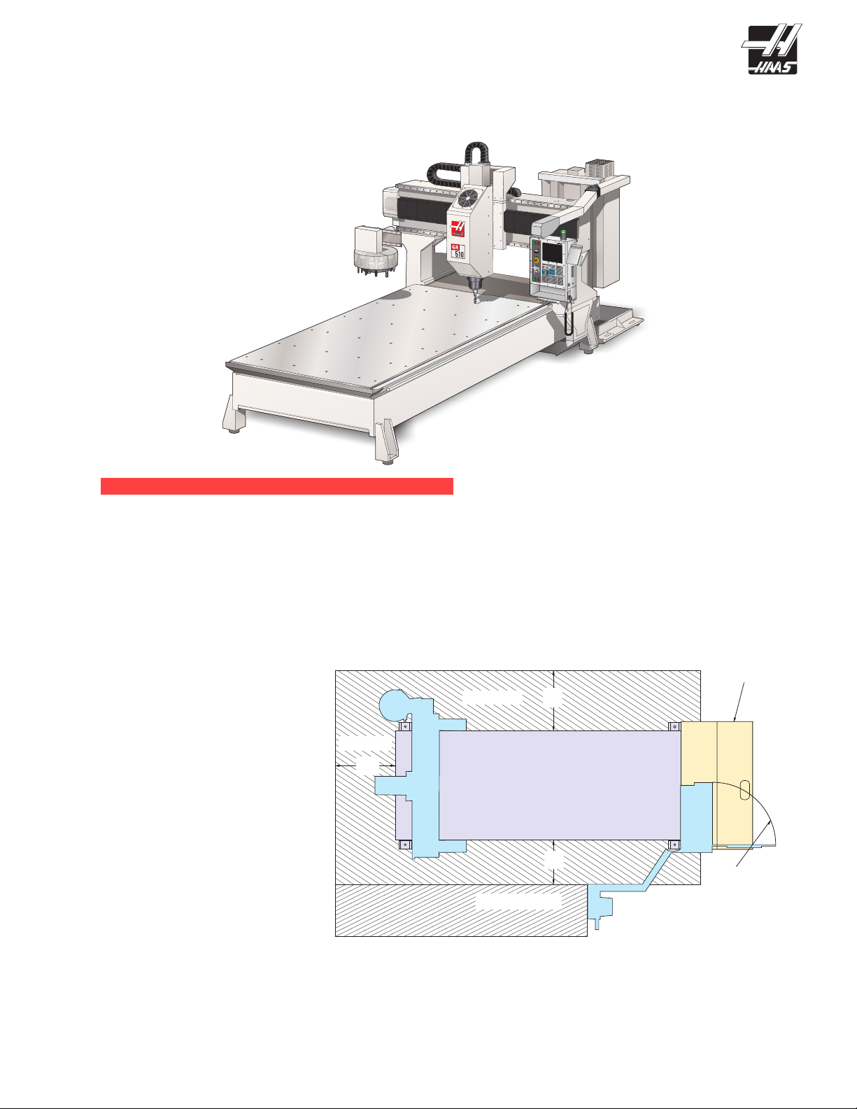
STAY CLEAR
A
STAY CLEAR
OPERATOR ZONE
B
BASE
CASTING
FRONT
C
GR 510/512 GR710/712
A
B
C
COOLANT TANK
36”
36”
30”
DOOR
CONTROL CABINET
36”
48”
42”
The tool changer may start at any time. All personnel must be clear of the tool changer, when the machine is
powered up.
© 2012 Haas Automation, Inc. 96-0056 rev P 3/12 1
Page 2

This machine is designed to be operated as an “Open
Architecture” machine. “Open Architecture” refers to a machine
that does not include every guard necessary to keep the
operator out of the machining envelope. To avoid accidents
the operator must stay within the Operator Zone (as shown in
the following gure), during machining operations. During the
operation of this machine all personnel must remain outside of
the Stay Clear Zone.
Areas of the machine, especially
on open frame mills, may have
unguarded areas. The installation of
the machine should be such that it
will limit the access to the machine.
As the machine may start unexpectedly personnel or property could be damaged.
This machine moves quickly. It is the shop owners responsibility to provide mea-
sures to safeguard the worker.
Photoelectric beams are used to stop the machine should personnel or equipment enter the protected area.
This system will also stop the machine should a large quantity of coolant and/or machining chips pass through
the beam. If this happens change the set-up or machining process to avoid this condition.
1. INSTALLATION
Air Requirements
The Gantry mill requires 4 scfm (standard cubic feet/minute) of air at 100 psi.
Electrical Requirements
AC input power is three phase Delta or Wye power, except that the power source must be grounded (e.g. leg
or center leg for delta, neutral for Wye)
Frequency range of 47-66 Hz
Line voltage that does not uctuate more than ± 5%
Harmonic distortion not to exceed 10% of the total RMS voltage
Voltage Requirements High-Voltage Requirements
(195-260V) (354-488V)
Power Supply 50 AMP 25 AMP
Haas Circuit Breaker 40 AMP 20 AMP
If service run from elec. panel
is less than 100’ use: 8 GA. Wire 12 GA. Wire
If service run from elec. panel
is more than 100’ use: 6 GA. Wire 10 GA. Wire
NOTE: The gantry mill will perform better when anchored. Refer to the Haas document
ES0095 for anchoring instructions.
The installation of the Gantry Router is similar to the VF-Series mill (see the VF-Installation section of the
Vertical Reference Manual. Some general guidelines follow.
© 2012 Haas Automation, Inc. 96-0056 rev P 3/12 2
Page 3
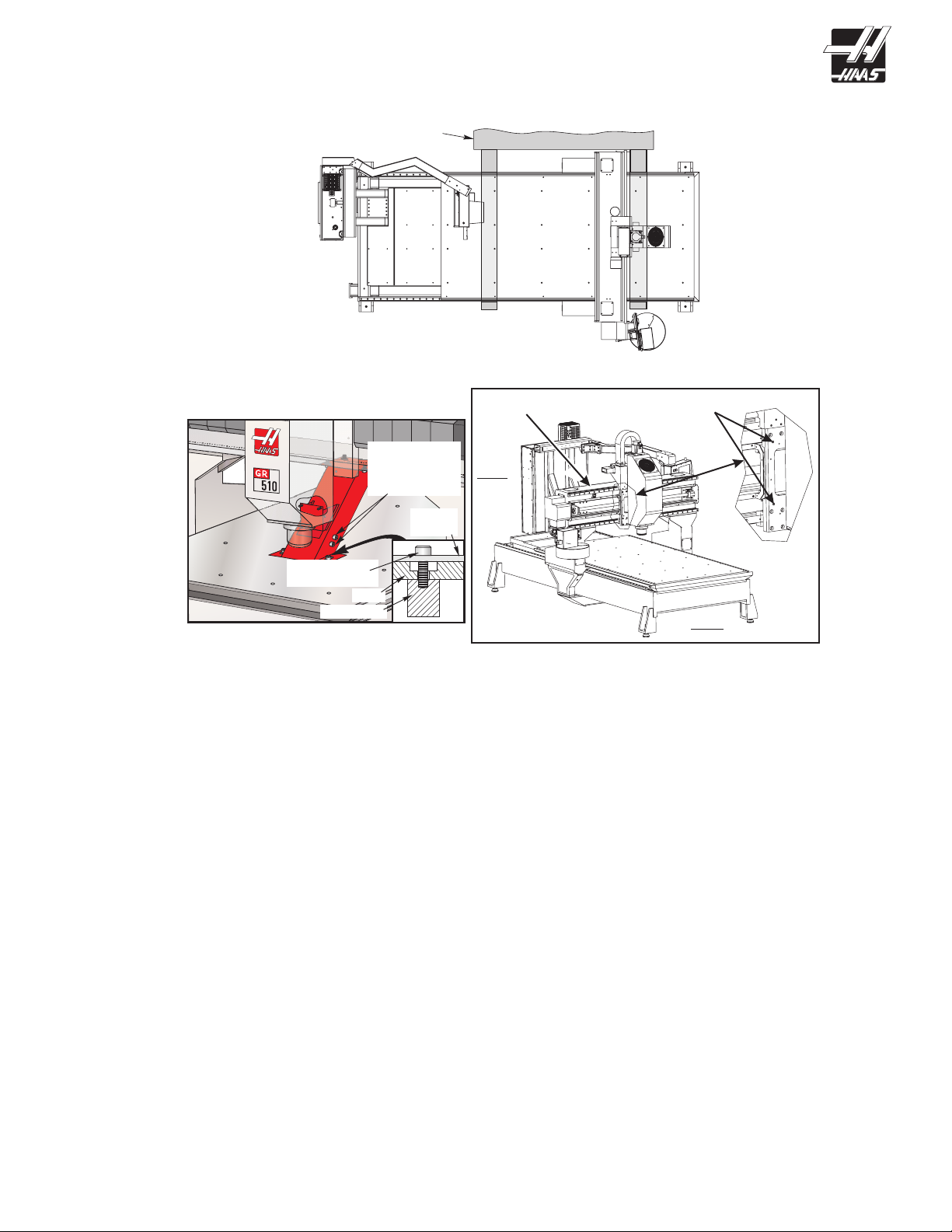
Moving the GR-Series Mill.
Use a forklift with at least a 18,000 lb rating. Use the illustration as a guide for proper fork truck lifting.
Fork Truck
Shipping Bracket Removal
Remove shipping bolts before
operating the mill
New boltsto
replace the
shipping bracket
boltsin the table
Shipping
Bracket
Bridge
Rear
Bolts used for
Shipping (Longer)
Table
Steel Frame
Front
Remove the two long bolts that secure the lower shipping bracket to the table. The shipping bracket has two
additional bolts threaded into it. These bolts replace the long shipping bolts in the table. The long shipping
bolts should be threaded into the shipping bracket and stored in the event the machine is moved.
Remove the shipping brackets which secure the head to the table. In addition there are shipping bolts which
hold the Y-axis to the bridge that need to be removed. Install the sheetmetal cover over the sub-plate, on the
tool changer side of the machine.
© 2012 Haas Automation, Inc. 96-0056 rev P 3/12 3
Page 4

1.1 OptiOnal 20-pOcket tOOl changer
Machines with the 20-pocket tool changer are shipped with the tool changer reversed. Which saves space
and reduces shipping charges. Before operating the machine the tool changer needs to be installed correctly.
Shipping Position Operating Position
To do this the tool changer must be removed, and then installed in the operating position and aligned.
To remove the tool changer a lifting device will be necessary. The tool changer is very heavy
and needs to be supported with additional mechanical means.
1. Support the tool changer with an overhead crane or forklift.
NOTE: It is not necessary to disconnect any of the cables, but be careful not to tug on them
when maneuvering the tool changer to the operating position.
2. Remove the tool changer by removing the four bolts which secure the tool changer to the bracket.
3. Turn the tool changer around and reinstall. Leave the bolts loose in order to perform nal alignment
© 2012 Haas Automation, Inc. 96-0056 rev P 3/12 4
Page 5

aligning the tOOl changer
1. Jog the mill to machine 0 in the Y and Z axes. Place a tool in the spindle and then orient the spindle.
2. Verify there is an empty pocket in the tool changer facing the spindle, then command a tool change. Press
E-Stop as the tool changer begins to move.
3. Manually push the tool changer towards the spindle and verify the spindle orientation and height of the
spindle. If necessary adjust parameter 257. Important: As the tool changer engages the tool, make certain
the height is correct. You may need to rotate the tool by hand as the tool changer engages.
Spindle Dog
A
B
Spindle
Tool / Tool Changer Alignment X-Axis Alignment
4. As you move the tool changer in, check the alignment of the tool changer in the X-axis. Adjust the tool
changer assembly at the point it mates with the mill, if necessary. The tool should be centered between the
tool changer ngers. X-Axis Alignment – This gure illustrates the mounting bolts and alignment pins for
alignment in the X-axis.
5. Once aligned, tighten the bolts that secure the tool changer to the bridge.
6. Rotate the spindle, by hand, until the tool is centered in the pocket.
7. Enter DEBUG in the control. Go to the POS-RAW-DAT screen and write down the spindle encoder counts.
This number is just to the right of the system time. Enter this number in Parameter 257 (Spindle Orient Offset); Exit DEBUG.
8. Press Zero Return, then Zero Single Axis, this will move the tool changer shuttle out. Repeat steps 1
through 3 and verify the alignment.
9. Remove the tool from the spindle. Command a tool change to an empty pocket in the tool changer.
10. Place tool in the spindle and command a tool change. If further adjustment is necessary repeat the previ-
ous steps.
Verify Alignment
Place a tool in the spindle and command a tool change. Check for proper engagement. Put another tool in
the spindle and command a tool change to a pocket 180º from the rst tool. Check for proper engagement
between the spindle and tool changer. If the tool changer does not move in to the proper position for the tool
change the shuttle stroke may need to be adjusted. See the “Shuttle Stroke Adjustment” section of the Ser-
vice manual.
Measure the distance from the table to the tool holder at the tool change position. Rotate the tool changer
carousel 90º and check the height again. Do the previous steps again at the 180º and 270º intervals. This will
verify that the tool changer assembly is parallel to the table.
© 2012 Haas Automation, Inc. 96-0056 rev P 3/12 5
Page 6

Setting parameter 64 (tOOl change OffSet)
Please read this section in its entirety before attempting to set Parameter 64.
NOTE: Setting 7 must be set to “OFF” before setting Parameter 64.
1. Without a tool in the spindle taper, initiate a tool change and stop the tool changer using the E-STOP button, just before the tool changer reaches the spindle. Insert a tool holder into the pocket facing the spindle.
2. Using a .0005 indicator and suitable magnetic base, zero off of bottom left edge “A” of tool holder (looking directly into pocket). Move indicator to bottom right edge “B” of tool holder. Any difference between these
edges should be equally divided. For example: if a difference of .002 from left side to right side edge, adjust
indicator dial so that indicator reads .001 when it is on either edge. This gives you the tool offset reference.
Checking Tool Offset Reference.
3. Carefully (so as not to disturb relative position) move indicator to one side. Remove tool from tool changer.
4. Press Zero Return, then Zero Single Axis, this will move the tool changer shuttle out.
5. Place a tool in the spindle.
6. Press Z and Home G28 to bring the Z axis to the tool change position.
7. Carefully (so as not to disturb relative position) place indicator under spindle and indicate on bottom left
edge of the tool holder.
If spindle head is too far in the negative (-) or the positive (+) direction, go to JOG mode and choose Z-axis.
Jog Z-axis in the necessary direction until it reads zero (0).
8. Enter DEBUG, and go to Position Raw Data page. Write down number for Z-axis from the “actual” column.
If Z-axis ‘actual’ display is negative (-), add the number to Parameter 64. If the number is positive (+), subtract
it from Parameter 64, ignoring the decimal points.
Example:
Parameter 64 = 917207
Z-axis Actual = .0390
917207 - 390 = 916817
9. To insert the calculated new number, place cursor at Parameter 64, type in new number and push WRITE
key. ZERO RET Z-axis to initialize the new Parameter 64. Press Z and Home G28 to bring the Z axis down.
10. Recheck the offset with the indicator (Steps 1-5).
11. Insert tool holder in spindle taper and change tool. Watch closely as tool changer approaches spindle.
12. Change setting 7 to “ON”.
13. Exit Debug.
© 2012 Haas Automation, Inc. 96-0056 rev P 3/12 6
Page 7

1.2 pendant arm
The Gantry Mill has the pendant arm secured to the table for shipping. DO NOT operate the mill with the arm
in this position.
Remove Bolt
and Spacer
(and Washer
GR-710/712)
Shipping Position Operating Position
Replace Bolt
and Spacer
(and Washers
GR-710/712)
Swing the pendant arm away from the table. Remove the bolt and spacer which is stored in the top of the arm
joint, and install the bolt and spacer in the front of the joint. Loosen the clamps on the exible boot. Position
the boot over the joint and tighten the clamps.
1.3 phOtOelectric BeamS
WARNING!! THE ELECTRIC SAFETY GUARDS MUST BE SET-UP BEFORE JOGGING ANY AXIS.
The GR-Series mills comes factory equipped with photoelectric beams. Once this system is set up the machine will halt should personnel or equipment enter the protected area. The beam xtures are located at each
corner and scan the length (the areas the gantry legs travel) of the table. Note that the width is not protected.
The mill will go into feed hold and the spindle will stop if the electronic beam is broken. When this happens
clear the area close to the machine of personnel or equipment and press Cycle Start to continue.
The mill will arrive with the beam sensor and reector support brackets in their shipping position. These will
have to be oriented correctly to align with one another.
Shipping
Position
Operating
Position
Align Reflector
Set-up
Each side of the table has a bracket with a reector and a bracket with a sensor. These need to be positioned
correctly in order for the system to function.
1. Loosen the single bolt and rotate the arm 90º. This will have to be done at each corner of the machine.
Snug the bolts.
2. Move to the bracket with the sensor on it and adjust it until the lights (red and green) on the sensor come
on. Do this with both sensors.
© 2012 Haas Automation, Inc. 96-0056 rev P 3/12 7
Page 8

3. Once aligned, tighten all the bolts on the four guards. Verify the lights on both sensors are still on.
9”
26”
Nine Inches From
Side of Machine
1.4 leveling
Leveling of the machine is required to obtain the correct right angle geometry of the X, Y, and Z axes. Incorrect leveling will result in out-of-round circle milling and incorrect linear interpolation.
Use a precision bubble level with each division equal to 0.0005 inch per 10 inches, or .05 mm per meter, or 10
seconds per division. Before starting, check the accuracy of your level. Set it on the table on the X-axis and
record the reading. Then turn it 180o and the reading should be the same. If it is not, the level is out of calibration and should be adjusted before you continue.
Screw the four leveling screws at the corners through the base until the base is 2½” to 3” above the oor. That
translates into a minimum of one inch of the leveling screw extending out of the bottom of the base of the
machine, or one inch between the pads and the casting. Turn each screw until the tension is about the same
as the tension on the other screws. Screw the jam nuts onto the four (4) leveling screws, but do not tighten
them down.
rOugh leveling
1. Place the precision bubble level on the center of the table parallel with the table (X-axis).
2. If the bubble goes to the front of the level, then the front end of the machine is high. Conversely, if the
bubble goes to the rear, it means that the rear end is high. Raise the two front or back leveling screws evenly
until the bubble is centered.
3. Rotate the level 90° parallel with the Y-axis. Adjust the right or left leveling screws as needed until level.
4. Repeat this process until both directions are level.
remOve pitch and rOll (twiSt)
1. Use Handle Jog set for 0.01 on the X-axis for this procedure. This provides a good rate of travel for manually moving the bridge. Jog the X-axis to machine zero and the Y-axis to the middle of travel.
2. Place the level on the bridge parallel to the X-axis to check the pitch. Zero the level by shimming it. Jog the
bridge to the other end to the machine. If the bubble goes to the front of the level, then the front end of the
machine is high. And conversely, if the bubble goes to the rear, it means that the rear end is high. Raise both
screws on the low end until level.
3. Place level parallel to the Y-axis on the bridge to check for roll on the table. Zero the level by shimming it.
4. Jog bridge to other end of machine. If the bubble goes toward the right, the right front corner of the machine
is too high. And conversely, if the bubble goes to the left, the left front corner is too high. Adjust as needed.
5. As process continues, leveling screws are turned in smaller increments — 1/4 turn, 1/8 turn, and smaller.
Also, as machine is leveled, make sure tension continues to be equal on the screws at all four corners.
© 2012 Haas Automation, Inc. 96-0056 rev P 3/12 8
Page 9

Repeat these steps until the machine is level. When leveling is completed, tighten the jam nuts on the leveling
screws. Check again that all the screws are sitting tight against the pads.
Check the leveling screws a few days after installation. The foundation may settle which could affect the ma-
chine’s stability.
chip Shield inStallatiOn
1. Fasten the chip shield to the chip shield bracket with the
two plastic knobs.
2. It is important to ensure that the chip shield is lower than
the longest tool in the tool changer. Adjust the chip shield by
loosening the plastic knobs and sliding the shield up or down
on the bracket.
NOTE: If the chip shield is not lower than the longest
tool, the chip shield and the tool will collide
during a tool change and can cause damage.
2. OPERATION
Tool Changer
Follow these specications to avoid damaging the tool changer:
• Use the correct tooling: BT or CT.
• The maximum tool weight allowable is 12 lbs per pocket, 120
lbs total, with 3.5” maximum tool diameters.
Table
• The maximum weight allowable on the GR-510 table is
6000 lbs distributed evenly.
CAUTION!
• Extremely heavy tool weights should be distributed
evenly.
PLASTIC KNOBS
• Ensure there is adequate clearance between tools in the
tool changer before running an automatic operation. This
distance is 3.6” for a 10 pocket or a 20-pocket tool changer.
© 2012 Haas Automation, Inc. 96-0056 rev P 3/12 9
Page 10

3. MAINTENANCE
The axes must be lubricated once a month. The axes are lubricated manually and have grease ttings on
them. Use a synthetic grease with an NLGI grade of 1.5 or 2. Pump with 2 strokes of the included grease
gun at each tting. The grease tting for the Y-axis and Z-axis is on the operator side of the sub plate. Each
column has a grease tting mounted in it and the X-axis ball screw grease tting is under the machine. It is
accessed by moving the gantry to the forward-most position.
Machines with an optional spindle may have a separate oiling system. Check monthly and add oil if required.
If equipped, check coolant level each 8 hour shift.
Coolant Tank
Clean the coolant tank each week. The coolant hoses may need to be removed from the pump, lter and if
equipped, auxiliary lter in order to gain better access to the tank. Mark the hoses from the coolant pump and
lter so they can be reinstalled to the proper tting. It is possible to put the hoses on the wrong port, so it is
very important that the hose are marked properly so they can be reinstalled correctly.
Grease Ports
M
Grease Ports
Grease
Port
© 2012 Haas Automation, Inc. 96-0056 rev P 3/12 10
 Loading...