


Instruction Manual
Shaking Water Bath
SWB25
Part No. 003-4190
1-1-067-2 / 09.1998
Gebr. HAAKE GmbH HAAKE (USA) Rheo s.a. ( France)
Dieselstraße 4 53 W. Century Road 99 Route de Versailles
D-76227 Karlsruhe Paramus, NJ 07652 91160 Champlan
Tel.+49(0)18050HAAKE
oder+49(0)721 4094-444 Tel.201 265 7865 Tel.+33 1 64 54 0101
Fax +49(0)721 4094-418 Fax 201 265 1977 Fax +33 1 64 54 0187
E-mail:helpdesk@haake.de http://www.haake-usa.com http://www.rheo.fr

Table of Contents
1
1. Key to Symbols 3. . . . . . . . . . . . . . . . . . . . . . . . . . . . .
1.1 Symbols used in this manual 3. . . . . . . . . . . . . .
1.2 Symbols used on the unit 3. . . . . . . . . . . . . . . . .
2. Quality Assurance 4. . . . . . . . . . . . . . . . . . . . . . . . . .
3. Your Contacts at HAAKE 4. . . . . . . . . . . . . . . . . . . .
4. Safety Notes 5. . . . . . . . . . . . . . . . . . . . . . . . . . . . . . . .
5. Unit Description 7. . . . . . . . . . . . . . . . . . . . . . . . . . . .
5.1 Safety features 7. . . . . . . . . . . . . . . . . . . . . . . . . .
5.2 Safety element 7. . . . . . . . . . . . . . . . . . . . . . . . . .
5.3 Applications 7. . . . . . . . . . . . . . . . . . . . . . . . . . . .
6. Unpacking / Setting Up 8. . . . . . . . . . . . . . . . . . . . . .
6.1 Transportation damage? 8. . . . . . . . . . . . . . . . .
6.2 Information concerning the CE sign 8. . . . . . . .
6.3 Contents 9. . . . . . . . . . . . . . . . . . . . . . . . . . . . . . .
6.4 Ambient conditions according
to DIN EN 61010 9. . . . . . . . . . . . . . . . . . . . . . . .
7. Panel Controls and Indicators 10. . . . . . . . . . . . . . .
8. Assembly/Connecting Up 11. . . . . . . . . . . . . . . . . . . .
8.1 Connecting the platform to the guide rod 11. . .
8.2 Connecting to a mains socket 11. . . . . . . . . . . . .
8.3 Changing the mains plug
(e.g. for Great Britain) 11. . . . . . . . . . . . . . . . . . . .
8.4 Fuses on the unit 11. . . . . . . . . . . . . . . . . . . . . . . .
9. Setting up and starting 12. . . . . . . . . . . . . . . . . . . . . .
9.1 Attaching clamps for vessels to the platform 12
9.2 Filling in the bath liquid 12. . . . . . . . . . . . . . . . . . .
9.3 Ideal operating conditions for the shaking
movement 12. . . . . . . . . . . . . . . . . . . . . . . . . . . . . .
9.4 Operational safety 13. . . . . . . . . . . . . . . . . . . . . . .
9.5 Draining 13. . . . . . . . . . . . . . . . . . . . . . . . . . . . . . . .
10. Operating 14. . . . . . . . . . . . . . . . . . . . . . . . . . . . . . . . . .
10.1 Switching on 14. . . . . . . . . . . . . . . . . . . . . . . . . . . .
10.2 Displaying the preset temperature 14. . . . . . . . .
10.3 Adjusting the set temperature 14. . . . . . . . . . . . .
10.4 Heating control lamp 15. . . . . . . . . . . . . . . . . . . . .
10.5 Displaying the shaking frequency 15. . . . . . . . . .
10.6 Adjusting the shaking frequency 16. . . . . . . . . . .
11. Special functions 17. . . . . . . . . . . . . . . . . . . . . . . . . . .
11.1 Adjusting the default values 17. . . . . . . . . . . . . . .
11.2 Adjusting the RTA values (CT) 17. . . . . . . . . . . .

Table of Contents
2
12. Excess Temperature Protection 18. . . . . . . . . . . . . .
12.1 Excess temperature protection dial 18. . . . . . . .
12.2 Setting the excess temperature 18. . . . . . . . . . .
13. Fault display 19. . . . . . . . . . . . . . . . . . . . . . . . . . . . . . . .
13.1 Sensor bath/short circuit 19. . . . . . . . . . . . . . . . . .
13.2 Motor 19. . . . . . . . . . . . . . . . . . . . . . . . . . . . . . . . . .
13.3 Range sensor 19. . . . . . . . . . . . . . . . . . . . . . . . . . .
14. Special Accessories 20. . . . . . . . . . . . . . . . . . . . . . . .
15. Maximum clamp number for the moveable
platform for ... 23. . . . . . . . . . . . . . . . . . . . . . . . . . . . . .
16. Technical Specifications 24. . . . . . . . . . . . . . . . . . . . .
16.1 Unit 24. . . . . . . . . . . . . . . . . . . . . . . . . . . . . . . . . . . .
16.2 Fuse values 24. . . . . . . . . . . . . . . . . . . . . . . . . . . .

!
+
_
C
°
n
stop
Key to Symbols
3
1. Key to Symbols
1.1 Symbols used in this manual
Warns the user of possible damage to the unit, draws
attention to the risk of injury or contains safety notes
and warnings.
Denotes an important remark.
1
Indicates the next operating step to be carried out
and…
⇒ …what happens as a result thereof.
1.2 Symbols used on the unit
Caution: Read the instruction manual!
Adjustment possibility for setting the cut-off point for
excess temperature protection
Instrument in ”off” position
Instrument in ”on” position
Menu selection
Value alteration (+) higher / ( – ) lower
Stop / Enter key
Temperature key
Shaking frequency

Quality Assurance / Your Contacts at HAAKE
4
2. Quality Assurance
Dear customer,
HAAKE implements a Quality Management System certified
according to EN 29001.
This guarantees the presence of organizational structures
which are necessary to ensure that our products are developed, manufactured and managed according to our customers expectations. Internal and external audits are carried out
on a regular basis to ensure that our QMS system is fully
functional.
We also check our products during the manufacturing process to certify that they are produced according to the specifications as well as to monitor correct functioning and to confirm that they are safe. This is why we initiate this monitoring
process of important characteristics already during
manufacturing and record the results for future reference.
The “Final Test” label on the product is a sign that this unit
has fulfilled all requirements at the time of final manufacturing.
Please inform us if, despite our precautionary measures,
you should find any product defects. You can thus help us to
avoid such faults in future.
3. Your Contacts at HAAKE
Please get in contact with us or the authorized agent who
supplied you with the unit if you have any further questions.
Gebrüder HAAKE GmbH,
Dieselstrasse 4,
D-76227 Karlsruhe
GERMANY
Tel. +49 (0)18050HAAKE
or +49 (0)721 4094-444
Fax +49 (0)721 4094-418
E-mail helpdesk@haake.de
The following specifications should be given when product
enquiries are made:
– Unit name printed on the front of the unit,
– TYP as specified on the name plate.

!
!
!
!
!
!
!
!
!
Safety Notes
5
4. Safety Notes
These notes are intended to draw your attention to risks
which only YOU can recognize and avoid or overcome. They
are intended t o enhance your own safety consciousness.
We have set the highest quality standards for ourselves and
this unit during development and production. Every unit
meets relevant safety regulations. The correct unit usage
and proper h andling i s h owever s olely your r esponsibility.
The intended workplace should correspond to a laboratory
or pilot plant environment. The user should have an education level which is at least equivalent to a trained laboratory
worker or specialized chemist. The following list should be
seen as an example.
The device may not be operated if there are any doubts
regarding a safe operation due to the outer appearance
(e.g. damages).
A safe operation of the instrument cannot be guaranteed if the user does not comply with this instruction
manual.
Ensure that this manual is always at hand for every unit
operator.
Only use this unit solely for the intended application.
Repairs, alterations or modifications must only be car-
ried out by specialist personnel. Considerable damage
can be caused by improper repairs. The HAAKE service
department is at your disposal for repair work.
Do not operate the unit with wet or oily hands.
Do not clean the unit with solvents (fire risk!) – a wet
cloth soaked in household detergent is normally sufficient.
This device is not designed according to the standard
EN 60601-1: 1990 (DIN VDE 0750-1 and IEC 601-1) and
should not be operated in rooms used for medical purposes and/or in the vicinity of patients.
Only use heat transfer liquids recommended by HAAKE.
Please refer to the respective EC – Safety Data Sheet.

!
!
Safety Notes
6
The temperature controlling i.e. immersing o f test tubes,
Erlenmeyer flasks or similar objects directly within the
unit constitutes normal circulator practise.
We do not know which substances are contained within
thes e vessel s. Many substances are dangerous:
• inflammable, easily ignited or explosive
• hazardous to health
• environmentally unsafe
Y ou alone are responsible for the handling of these substances! Our advice:
• If in doubt, consult a safety specialist.
• Read the product manufacturer’s or supplier’s
“
EC – SAFETY DATA SHEET
”
• Read relevant regulations concerning dangerous
materials
• Observe relevant guidelines for laboratories in your
country
The following measures were taken for the protection of
the operator:
• Protection Class I according to VDE 0106 T1
i.e. protection against electric shocks by grounding all
parts which carry the risk of electric contact.
The device must only be connected to mains receptacles with a protective ground.
• Protection IP 20 according to EN 60529
i. e. regarding the protection against accidently touching live parts and damage by foreign matter, it has been
ensured that foreign bodies with a thickness or diameter of more than 12 mm cannot penetrate.
No special precautions were taken against the penetration of water and dust. The device should therefore not be used in a dusty atmosphere or in the neighborhood of spray water.
Do not insert wires or tools in any of the openings.
Complete separation from the mains is required
when:
• all dangers caused by this device are to be
avoided,
• cleaning is carried out,
• repairs or maintenance by specialist personnel is
about to be carried out
Complete separation means:
Pull out the mains plug!

Unit Description
7
5. Unit Description
5.1 Safety features
The comprehensive safety system is designed on the principle of the concept of the “single fault” (EN 61010). This assumes that two separate faults do not occur simultaneously .
This system therefore offers protection against
one
(single)
fault. This one fault will effectively occur automatically if
you...
• do not read this manual,
• do not correctly set the excess temperature protection,
i.e. your safety reserves have already been used up.
5.2 Safety element
The unit is equipped with an excess temperature protection.
The unit can only be used with non-flammable liquids such
as
water
or
water with antifreeze
.
The safety element measures the surface temperature of the
heating element. If this exceeds a certain temperature (due
to e.g. a leakage in the liquid circuit or a liquid shortage), the
safety element is triggered.
If a safety feature is triggered…
• fault display lights indicate the fault,
• the safety-relevant components of the heating unit
(heating element ) are switched off immediately i.e. the
safety circuit transfers the unit to a stable, safe condition,
• the water in unit gradually adjusts to ambient tempera-
ture.
5.3 Applications
Temperature controlling and shaking of samples directly in
the bath vessel.The samples have to be inserted into flasks
or beakers.

Unpacking / Setting Up
8
6. Unpacking / Setting Up
6.1 Transportation damage?
• Notify carrier (forwarding merchant, railroad) etc.
• Compile a damage report.
Before return delivery:
• Inform dealer or manufacturer
(Small problems can often be dealt with on the spot).
6.2 Information concerning the CE sign
HAAKE circulators and cryostats carry the CE sign which confirms that they are compatible with the EU guideline
89/336/EEC (electromagnetic compatibility). The tests are carried out according to module H (official sheet L380 of the European Community) as our quality assurance system is certified
according to DIN / ISO 9001.
It was tested according to the strict EMV test requirements of
the EN61326 (EMV requirements for electrical equipment for
measuring technology, conduction technology and laboratory
usage). This means it was tested for interference resistance
and interference emission according to industrial conditions.
The following basic standards were applied in detail:
Interference resistance:
EN61000–4–2 electrostatic discharge
EN61000–4–3 electromagnetic fields
EN61000–4–4 fast transients
EN61000–4–5 surge voltages
EN61000–4–6 wire–guided HF–signals
EN61000–4–8 magnetic field of mains frequency
EN61000–4–11 voltage drop/short–time interruption
Interference emission:
CISPR16/class A wire–guided interference emission
CISPR16/class A radiated interference emission
The application in industrial environments is thus possible.
A declaration of conformity is supplied with the ordered unit on
request.
Our strict standards regarding operating quality and the resulting considerable amount of time and money spent on development and testing reflect our commitment to guarantee the high
level of quality of our products even under extreme electromagnetic conditions. Practice however also shows that even units
which carry the CE sign such as monitors or analytical instruments can be affected if their manufacturers accept an interference (e.g. the flimmering of a monitor) as the minimum operating quality under electromagnetic compatibility conditions. For
this reason we recommend you to observe a minimum distance
of approx. 1 m from such units.
The CE–sign also certifies the conformity with the EU–directive
72/23/EWG (low voltage regulation). The applied standards
are EN 61010–1 and EN 61010–2–010.

Unpacking / Setting Up
9
6.3 Contents
1 Base unit with mains cable
1 Moveable platform with 4 rollers
1 Rubber connection piece
1 Instruction manual
1 Warranty card (please fill out and return)
6.4 Ambient conditions according to DIN EN 61010
• indoors, max. 2000 meters above sea level,
• ambient temperature 5 ... 40° C,
• relative humidity max. 80%/31°C (→ 50%/40°C)
• excess voltage category II, contamination level 2
Panel Controls and Indicators
10
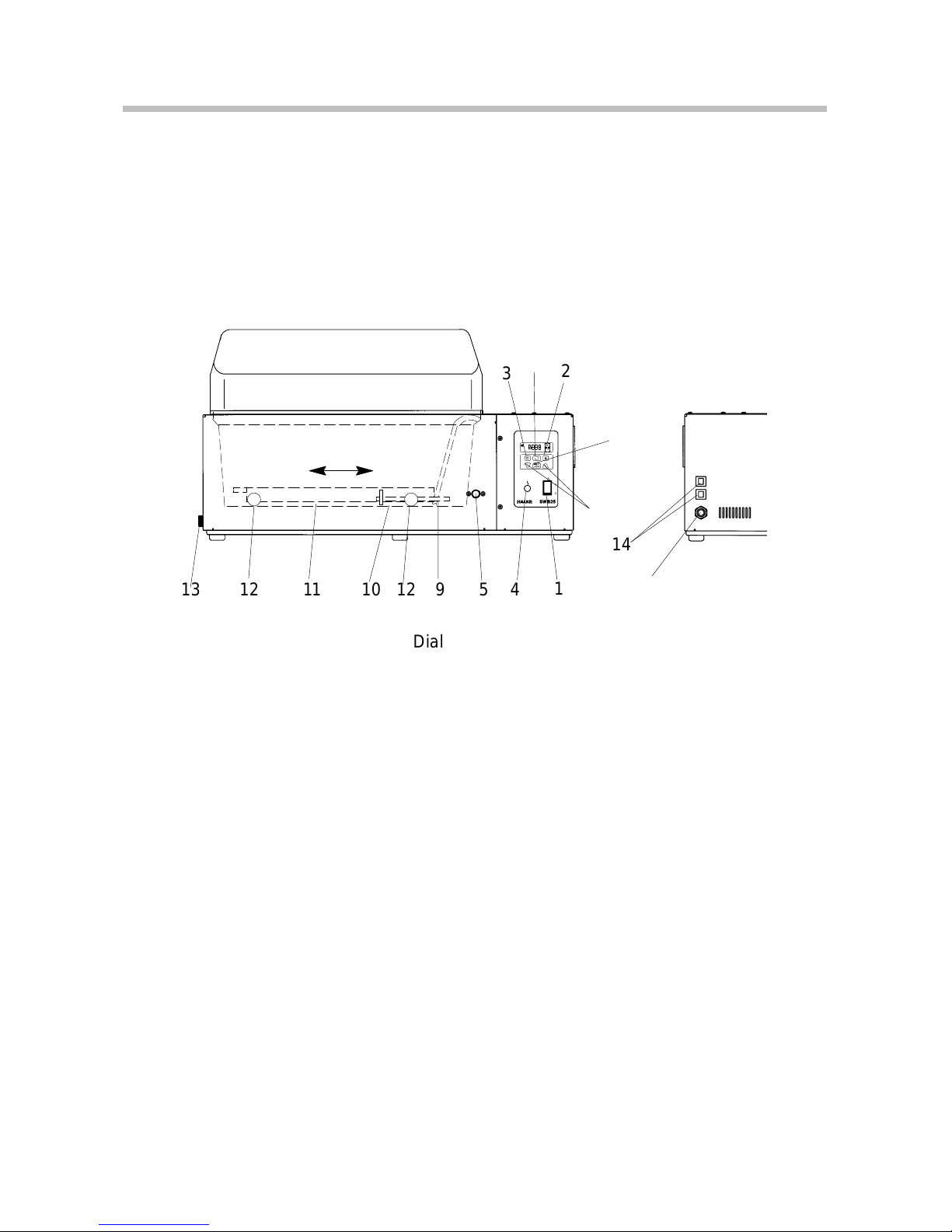
7. Panel Controls and Indicators
14
13 12 11 10 12 9
2
3
45
1
7
8
6
15
(1) Main switch
(2) Dial for shaking frequency
(3) Preset temperature dial
(4) Malfunction indicator light
(5) Excess temperature dial
(6) Changing the value
(7) Menu selection key
(8) Stop / Input key (Enter)
(9) Guide rod
(10) Rubber connection
(11) Moveable platform
(12) Rollers
(13) Drain plug nozzle
(14) Fuses
(15) Mains cable

230 V
115 V
!
!
!
Assembly/Connecting Up
11
8. Assembly/Connecting Up
8.1 Connecting the platform to the guide rod
Lift left end of the platform (11) until the rubber connection
(10) at the bathbottom can be picked up and placed over the
pin at the underside of the platform.
8.2 Connecting to a mains socket
The unit should only be connected to a grounded mains sokket. Before the unit is actually connected to the mains,
please compare the voltage indication on the name plate.
Voltage tolerances up to +/– 10% are acceptable.
8.3 Changing the mains plug (e.g. for Great Britain)
This should only be carried out by qualified spe-
cialist personnel!
The mains cable wires have the following colors:
Brown = Live
Blue = Neutral
Green/Yellow= Earth
8.4 Fuses on the unit
All units are equipped with automatic thermally-triggered
fuses.
If the fuse has triggered…
• the fuse does not have to be exchanged – resetting suf-
fices;
• a white marking is visible;
• a certain cooling down time should be allowed (approx.
5 min) before the (dip) switch can be pressed again.
Do not use tools; do not use force. Both destroy the
fuse.
If the fuse should be triggered again after resetting,
the unit probably has a defect. In this case the unit
should be sent in for servicing.

Setting up and Starting
12
9. Setting up and starting
9.1 Attaching clamps for vessels to the platform (11)
Spring clips can be supplied to secure round vessels, e.g.
Erlenmeyer flasks or beakers, to the platform.
Maximum clamp number see chapter 11.
9.2 Filling in the bath liquid
Liquid level: Can be selected anywhere between 50 and
180 mm (Thus, filling level dependent on objects used in the
bath.)
Only use
water
or
water with antifreeze
.
9.3 Ideal operating conditions for the shaking
movement
The following should be considered in order to warrant ideal
operating conditions:
a) Type and level of the bath liquid.
b) Number, size, and weight of the test vessels.
c) Amplitude of the shaking carriage movement.
d) Number of carriage cycles per time unit
(shaking frequency).
The limiting conditions for the shaking movement:
1) Too large a shaking movement will cause high
waves on the bath surface so that the liquid will
splash over the top.
2) Large and heavy test vessels are attached to the
platform and the amplitude and /or the frequency
are too high. This means an overload for the
shaking drive:
An overload could lead to a standstill of the driving
motor and eventually to its destruction if such
operating conditions are kept up over a longer
period of time.

!
Setting up and Starting
13
The following rule will help to arrive at ideal operating conditions:
At the beginning of the test, a small amplitude and a small
frequency should be selected. Then the values of these two
parameters may gradually be increased until the contents
of the test vessels are sufficiently shaken and mixed.
The shaking mechanism is also activated when the unit is
switched on. Please observe the notes above regarding the
shaking movement. It should especially be ensured that the
shaking motor is not blocked due to the choice of unsuitable
shaking motor parameters.
If the SWB25 is only to be used as a waterbath, the rubber
connection piece (10) of the platform (11) should be
removed.
9.4 Operational safety
The units are provided with an excess temperature safety
circuit, the cut-off temperature of which has to be set at the
dial button (5). In case of a temperature control malfunction
which could overheat the bath, the heater of the water bath
will be cut off. The malfunction indicator light (4) will then
come on.
9.5 Draining
The unit is drained at the nozzle 13.
1
Place a suitable vessel underneath nozzle.
Bear in mind that the liquid will run out in a slight arc.
2
Turn plug slowly until it becomes disengaged from the
thread.
The liquid will start to run out.
3
Possible residues can be drained by tilting the circulator slightly.
Hot heat transfer liquid should not be drained!
When certain conditions make draining necessary ,
please act safety conscious: Wear protective
clothing and protective gloves!

!
Operating
14
10. Operating
10.1 Switching on
Switch the unit on at the mains switch 1.
⇒ The display 16 briefly shows the device identification
”Sb25”, thereafter the version number of the operating
software, e.g. ”1.00” and then the actual shaking frequency.
⇒ The shaking mode is started. The motor slowly reaches
the set shaking frequency. Heating is started.
If the shaking frequency is too high, then interrupt
by pressing the ”Stop” key 8.
10.2 Displaying the preset temperature
Only possible in the temperture displaying mode
(Display 17 ”°C” is lit).
1
Press menu key 7:
⇒ Select preset temperature set temperature
Small display ”°C” blinks.
⇒ In display 16 the adjusted preset temperature is
shown.
10.3 Adjusting the set temperature
Only possible in the temperature displaying mode
(Display 17 ”°C” is lit).
1
Press the menu button 7:
⇒ Small display ”°C” blinks.
2
Press the temperature button 3:
⇒ Displayed temperature value in the display.
3
Increase (+) or decrease (–) the value shown in the display with the buttons 7.
The first degree of temperature change is thereby
passed slowly and thereafter the rate of temperature
change in the display is five times faster.
16
19
17
18
1
2
6
8
7
3

Operating
15
4
Press the enter button 8.
⇒ The selected value is stored as new set tempera-
ture and activated.
The new value is not saved until the Enter button
has been pressed. The circulator continues to use
the old set value.
The display 16 automatically switches back to actual temperature display after a short time.
10.4 Heating control lamp
The display 19 lights up when the heating is switched on (set
temperature is higher than the actual temperature).
⇒ display 19 lights up constantly during the heating up
phase,
⇒ display 19 flashes on and off during the control phase.
The display 19 does not light up if the heating is not activated
(set temperature is lower than the actual temperature).
The heat transfer is carried out by convection from the
heated bath bottom upwards. There are therefor small temperature gradients in the bath from the top to the bottom or
from the bath side to the bath middle. This should be
accounted for if a correction of the set temperature should be
necessary.
10.5 Displaying the shaking frequency
Only possible in the speed displaying mode
(Display 17 ”n” is lit).
1
Press menu key 7 :
⇒ Select shaking frequency.
Small display ”n” blinks.
⇒ In display 16 the adjusted shaking frequency is
shown.
16
19
17
18
1
2
6
8
7
3

Operating
16
10.6 Adjusting the shaking frequency
Only possible in the speed displaying mode
(Display 17 ”n” is lit).
1
Press the menu button 7:
⇒ Small display ”n” blinks.
2
Press the shaking frequency button 2:
⇒ Displayed shaking frequency in the display.
3
Increase (+) or decrease (–) the value shown in the display with the buttons 6.
The first shaking frequency change is thereby passed
slowly and thereafter the rate of shaking frequency
change in the display is five times faster.
4
Press the enter button 8.
⇒ The selected value is stored as new shaking fre-
quency and activated.
⇒ The motor slowly increases the shaking fre-
quency. By pressing the enter button 8 once
again, the actually reached frequency is stored
as new set frequency.
The new value is not saved until the Enter button
has been pressed. The unit continues to use the
old value.
The display 16 automatically switches back to actual shaking frequency display after a short time.
16
19
17
18
1
2
6
8
7
3

Operating
17
11. Special functions
11.1 Adjusting the default values
1
Switch on the unit and press both keys 6
(”–” and ”+”).
⇒ All adjusted parameters are set back on default
values.
SOLL = 20.0°C
n = 20 rpm
RTA CT = 0.00°C
⇒ In display 16 the message”CodE”appears.
11.2 Adjusting the RT A values (CT) (Temperature offset)
Only possible in the temperature displaying mode.
1
Change from actual value display to preset value
adjustment with key 7.
⇒ Preset value (LED 17 blinks fast)
2
Change from SOLL to RTA with key 7
⇒ ”c” (c0.00) appears on display 16.
⇒ RTA value (LED 17 blinks every 2 seconds)
3
Change the value shown on the display with the keys
6 up ”+” or down ”–” . The setting range for the temperature/RTA value is ±10°C
⇒ With negative values the display changes from
”c” to ”–”.
4
Press input key 8 (Enter).
⇒ The selected value is stored and activated as new
value.
Without pressing the Enter key the new value is not
stored. The unit goes on operating with the old
value.
16
19
17
18
1
2
6
8
7
3

5
5 4
1
5a
Excess Temperature Protection
18
12. Excess Temperature Protection
If a safety feature is triggered:
• The fault control lamp 4 lights up.
• all voltage conducting unit components (the heating
element) are switched off immediately i.e. the safety
circuit transfers the unit to a stable, safe condition.
The fault cause must be identified and remedied.
After the fault has been eliminated the unit can be started
again by pressing the outer ring 5a.
12.1 Excess temperature protection dial
It offers protection against dangers caused by an uncontrolled heating up of the heat transfer liquid above the desired set temperature.
The cut-off temperature is adjusted with the excess temperature setting dial 5.
Proper protection can only be guaranteed if the
cut-off point has been correctly set.
12.2 Setting the excess temperature
The cut-off point is set with the excess temperature dial 5
with a rough scale of temperature values arranged around
it. This scale, of course, can only serve as an approximate
setting means for this cut-off point. However, the cut-off point
can be determined to act exactly if the following procedure
is adhered to:
If for instance a bath liquid has a fire point of 60°C the unit
should cut off after reaching 35°C at the latest:
1
First set the desired set value using keys 6 (+), (–) to
exactly 35°C.
2
After the SWB25 has reached this temperature, turn
the excess temperature dial 5 backwards very slowly
(to the left) until the unit cuts off (acoustic signal, fault
message).
3
Starting the unit after the heat transfer liquid has cooled
down somewhat.
4
Then set the set temperature to the actual temperature
(< 35°C).
⇒ The unit can now be used for temperatures below
35°C. As soon as 35°C is reached, it is securely
switched off.

Fault Display
19
13. Fault display
13.1 Sensor bath/short circuit
At faults of the measured value recognition the message
”AL-F” is shown.
⇒ The display part ”AL” blinks, the heater is
switched of f , the shaking process is not interfered
as long as the fault is present.
When the measured value recognition has
regenerated itself the normal operation is contin-
ued.
13.2 Motor
Motor is set on drive speed setting >0 rpm
f there is no rotation at a drive speed setting of >0 the message ”AL-d” is shown.
⇒ The display part ”AL” blinks, the heater is
switched off as long as the defect is present.
When the motor starts rotating the normal opera-
tion is continued.
13.3 Range sensor
When any parameter (preset value, RTA) is out of its scope.
Change values according to chapter 11.
Should the defects appear regularly the unit has to be sent
to the service.

Special Accessories
20
14. Special Accessories
Order No.: Description: Additional information
333-0642 (1) Bath cover, roof shaped,
plastic
827-0310 (2) Plastic balls for covering
bath,
500 balls sufficient
for 0.2 m
2
000-8581 (3) Cooling coil for tap
water cooling
333-0259 (4) Basic rack, without any
attachments (with special
clamping device for shaking
platform)
w/o inserts

Special Accessories
21
Order No.: Description: Additional information
333-0129 (5) Universal basic rack for
test tubes
Can be used only as
normal water bath.
333-0130
333-0131
333-0132
(6) 2 Inserts for
86 tubes, 10 mm ø
2 Inserts for
46 tubes, 16 mm ø
2 Inserts for
23 tubes, 25 mm ø
Per basic rack (4)
2 sets (4 pieces)
333-0134
333-0135
(7) Plastic snappers for the
holes of the inserts to
accommodate tubes/flasks
with variable diameters.
Plastic snappers, 50 pieces
outside 16 mm ø,
inside 2 – 10 mm ø
Plastic snappers, 25 pieces
outside 25 mm ø,
inside 5 – 17 mm ø

Special Accessories
22
Order No.: Description: Additional information
000-8732
000-1980
000-1982
000-1990
000-1994
000-1995
(8) Clamps for flasks/
beakers
for 25 ml, flasks/beakers
up to 42 mm ø
for 50 ml, flasks/beakers
up to 51 mm ø
for 100 ml, flasks/beakers
up to 64 mm ø
for 250 ml, flasks/beakers
up to 85 mm ø
for 500 ml, flasks/beakers
up to 105 mm ø
for 1000 ml, flasks/beakers
up to 131 mm ø
These clamps can be fixed
directly to the shaking
platform or for quick
changing onto the basic
rack 333-0259
NOTE: If the basic rack 333-0259 is used, the four tapered pins
have to be assembled first. They are screwed into the movable
platform in place of the four screws. Now the rack can be positioned on the pins.

Maximum Clamp Number
23
15. Maximum clamp number for the moveable
platform for ...
40 x 25 ml ( 000-8732 ) 32 x 50 ml ( 000-1980 )
18 x 100 ml ( 000-1982 ) 12 x 250 ml ( 000-1990 )
8 x 500 ml ( 000-1994 ) 5 x 1000 ml ( 000-1995 )

Technical Specifications
24
16. Technical Specifications
16.1 Unit
Working temperature
range
°C 25 - 90°C
with tap water cooling °C 20 - 90°C
Temperature Accuracy ± K 0.2
Heater power 230V
115V
WW1500
1500
Control type PID
Excess temp. protection yes
Shaking amplitude mm 15
Shaking frequency min-120...200 (continuous)
Bath opening/depth mm 500 x 300 / 200
Bath capacity l 8 - 26
Bath vessel stainless steel, rust-free
Dimensions: (WxLxH) mm 650 x 340 x 260
Weight kg 18
Mains supply V/Hz 230/50-60 or 115/60
Total wattage VA 1600
16.2 Fuse values
Mains voltage
Fuse(s) at the
rear panel
Fuse(s)
in the unit
230V 2x10 A 1xT 0.63 A
115V 1x16 A 1xT 1.6 A
Part No. 003-4190
Subject to alterations Printed in Germany 1.1.067.2–09.98
 Loading...