

Page 1

H3C XE 200/2000 IP PBX
Operation Manual
Hangzhou H3C Technologies Co., Ltd.
http://www.h3c.com
Manual Version: T2-08162N-20070520-C-3.01
Page 2

Copyright © 2006-2007, Hangzhou H3C Techn ologies Co ., Ltd.
All Rights Reserved
No part of this manual may be reproduced or transmitted in any form or by any means
without prior written consent of Hangzhou H3C Technologies Co., Ltd.
Trademarks
H3C, , Aolynk, , H3Care,
, TOP G, , IRF, NetPilot,
Neocean, NeoVTL, SecPro, SecPoint, SecEngine, SecPath, Comware, Secware,
Storware, NQA, VVG, V
2
G, VnG, PSPT, XGbus, N-Bus, TiGem, InnoVision and
HUASAN are trademarks of Hangzhou H3C Technologies Co., Ltd.
All other trademarks that may be mentioned in this manual are the property of their
respective owners.
Notice
The information in this document is subject to change without notice. Every effort has
been made in the preparation of this document to ensure accuracy of the content s, but
all statements, information, and recommendations in this document do not constitute
the warranty of any kind, express or implied.
To obtain the latest information, please access:
http://www. h3c.com
Technical Support
customer_service@h3c.com
http://www. h3c.com
Page 3

About This Manual
Related Documentation
In addition to this manual, each H3C XE 200/2000 IP PBX documentation set includes
the following:
Manual Description
H3C XE 200/2000 IP PBX
Installation Manual
It provides information for the hardware
features, installation, configuration,
maintenance and troubleshooting involved in
the XE series.
H3C XE 200/2000 IP PBX
Command Manual
It provides information for the hardware
features, installation, configuration,
maintenance and troubleshooting involved in
the XE 200/2000.
H3C XE 200/2000 IP PBX
G-Remote User Manual
It introduces the graphic user interface and
the operation through the XE 200/2000.
Organization
H3C XE 200/2000 IP PBX Operation Manual is organized as follows:
Chapter Contents
1 Basic Configuration
Profiles the system characteristics and major
functions. It also describes command line
interfaces (CLIs), required configuration
environments, Comware CLI attributes and
basic Comware configuration. The interface
configuration covers the configuration on
Ethernet interfaces and VLANs. The routing
configuration involves the configuration on IP
unicast static routes.
2 Process Server Configuration
Focuses on the functions and configuration
procedure of the H.323 GateKeeper and SIP
Server.
3 Location Server Configuration
Elaborates on the functions and configuration
procedure of the Location Server.
Page 4

Chapter Contents
4 Feature
Describes the unique functions and features
that the IP PBX provides including number
translation, overload protection and backup
and load balancing.
5 System Management
Introduces Comware logging and debugging
center, file system and file operation, user
interface, user management system and NTP
configuration. SNMP configuration involves
the settings required when the IP PBX serves
as NMS Agent. Terminal service presents
allowable console terminal types and required
settings. System management covers
hierarchical command configuration,
RADIUS-based AAA security.
6 IP Performance and Application
Includes the fundamentals and configuration
of the IP address, IP applications, IP
performance, as well as the configuration
necessary when the IP PBX serves as HDCP
Server.
7 Media Server
Introduces the functions of the media server,
and describes the configuration steps of the
media server in details.
8 Call Services
Introduces the various voice services
provided with the XE voice servers, including
Subscriber Management Service, Emergency
Call Service, Inter-Group Call Restriction
Service, Outgoing Call Authority Control
Service, Abbreviated Dialing Service,
Do-Not-Disturb Service, Calling Line
Identification Services, Password Call
Service, Call Forwarding Services , Third
Party Call Termination Service, ONLY
Service, Time Limit Call Service, Third Party
Call Control Service, Callback-On-Busy
Service, Call Pickup Service, Call Intervention
Service, Dialing Test Service, Time
Announcement Service, MyRing Service,
CPCP Service, Automatic Operator Service,
Group Notification Service, Call Transfer
Service, Number Query Service and Alarm
Clock Service.
9 Appendix A
Introduces usage of the license of the XE
200/2000 IP PBX.
10 Appendix B Lists the acronyms used in the manual.
Page 5

Conventions
The manual uses the following conventions:
I. Command conventions
Convention Description
Boldface
The keywords of a command line are in Boldface.
italic
Command arguments are in italic.
[ ]
Items (keywords or arguments) in square brackets [ ] are
optional.
{ x | y | ... }
Alternative items are grouped in braces and separated by
vertical bars. One is selected.
[ x | y | ... ]
Optional alternative items are grouped in square brackets
and separated by vertical bars. One or none is selected.
{ x | y | ... } *
Alternative items are grouped in braces and separated by
vertical bars. A minimum of one or a maximum of all can be
selected.
[ x | y | ... ] *
Optional alternative items are grouped in square brackets
and separated by vertical bars. Many or none can be
selected.
&<1-n>
The argument(s) before the ampersand (&) sign can be
entered 1 to n times.
# A line starting with the # sign is comments.
II. GUI conventions
Convention Description
< >
Button names are inside angle brackets. For example, click
<OK>.
[ ]
Window names, menu items, data table and field names
are inside square brackets. For example, pop up the [New
User] window.
/
Multi-level menus are separated by forward slashes. For
example, [File/Create/Folder].
Page 6

III. Symbols
Convention Description
Warning
Means reader be extremely careful. Improper operation
may cause bodily injury.
Caution
Means reader be careful. Improper operation may cause
data loss or damage to equipment.
Note Means a complementary description.
Page 7

Basic Configuration
Page 8

Operation Manual – Basic Configuration
H3C XE 200/2000 IP PBX Table of Contents
i
Table of Contents
Chapter 1 H3C XE 200/2000 IP PBX Overview............................................................................1-1
1.1 Introduction........................................................................................................................1-1
1.2 Feature List........................................................................................................................ 1-1
Chapter 2 Command Line Interface for Configuration..............................................................2-1
2.1 Setting Up the Configuration Environment........................................................................2-1
2.1.1 Configuring the XE IP PBX through the CONSOLE Port........................................2-1
2.1.2 Configuring the XE IP PBX through the AUX Port.................................................. 2-3
2.1.3 Configuring the XE IP PBX through Telnet............................................................. 2-5
2.2 Command Line Interface ...................................................................................................2-8
2.2.1 Command Line View............................................................................................... 2-8
2.2.2 Command Line Online Help.................................................................................. 2-11
2.2.3 Command Line Error Information.......................................................................... 2-12
2.2.4 History Command .................................................................................................2-12
2.2.5 Edit Features......................................................................................................... 2-13
2.2.6 Display Features ................................................................................................... 2-13
2.2.7 Regular Expressions.............................................................................................2-14
2.3 Hot Keys .......................................................................................................................... 2-17
2.3.1 Classifying Hot Keys.............................................................................................2-17
2.3.2 Usage of the Hot Keys..........................................................................................2-18
2.3.3 Configuring Command Alias ................................................................................. 2-19
Chapter 3 Basic Configuration.....................................................................................................3-1
3.1 Basic Configuration of Comware.......................................................................................3-1
3.2 Ethernet Interface Configuration........................................................................................ 3-5
3.2.1 Introduction to the Ethernet Interface...................................................................... 3-5
3.2.2 Configuring the Ethernet Interface..........................................................................3-6
3.2.3 Displaying and Debugging Ethernet Interface ........................................................ 3-9
3.3 Static Route Configuration.................................................................................................3-9
3.3.1 Introduction to the Static Route...............................................................................3-9
3.3.2 Introduction to the Default Route ............................................................................ 3-9
3.3.3 Configuring a Static Route....................................................................................3-10
3.3.4 Configuring a Default Route.................................................................................. 3-10
3.3.5 Deleting all Static Routes...................................................................................... 3-10
3.3.6 Displaying and Debugging Routing Table.............................................................3-11
Page 9

Operation Manual – Basic Configuration
H3C XE 200/2000 IP PBX Chapter 1 H3C XE 200/2000 IP PBX Overview
1-1
Chapter 1 H3C XE 200/2000 IP PBX Overview
1.1 Introduction
H3C XE 200/2000 IP PBX (hereinafter referred to as XE IP PBX) is a part of H3C’s
integrated cross-industry V oIP solutio n designed for enterp rise users. It can integrate a
large number of voice devices into a voice network that is easy to maintain, manage
and upgrade. With the XE IP PBX, you can make full use of the functions available with
the voice gateways and IP telephone terminals and even obtain function enhancement.
Thus, your investment can be protected to the maximum extent.
As a VoIP server, the XE IP PBX can centralize management of devices such as voice
gateways and IP telephone terminals and uniformly process VoIP services. The major
functions that it provides include registration management, dialing routing management,
call control, and service processing:
1) Registration management: When receiving a register request from a voice
gateway or terminal, the XE IP PBX accepts or rejects the request according to the
registration management policy and records the dynamic information such as the
online state of the gateway or terminal as well.
2) Dialing routing management: The XE IP PBX maintains the number information of
voice gateways and terminals and a mapping table from number to IP address an d
port. When a voice gateway or terminal receives a dialed number, it sends a call
request to the XE IP PBX. Then the XE IP PBX searches for the number mapping
table to find the IP address and port number mapped to the dialed number.
3) Call control: The XE IP PBX supports call tracing, statistics in addition to call
connection, maintenance, and release. The XE IP PBX provides two approaches:
redirection and routing.
4) Service processing: Besides the basic call services, the XE IP PBX provides the
traditional PBX service. Service information can be set by administrators or users
through the GUI client or a terminal.
1.2 Feature List
Table 1-1 Functionality of the XE IP PBX
Attribute Description
Connectivity
LAN
protocol
Ethernet_II
Ethernet_SNAP
IEEE802.2
IEEE802.3
Page 10

Operation Manual – Basic Configuration
H3C XE 200/2000 IP PBX Chapter 1 H3C XE 200/2000 IP PBX Overview
1-2
Attribute Description
IP service
ARP
Static DNS service
Network
protocol
IP routing Static routing management
Security AAA Local authentication and authorization
Reliability
Dual power redundancy (XE 2000)
Automatic temperature sensor inside the chassis (XE 2000)
Command
line
interface
(CLI)
Local configuration through the CONSOLE port
Remote configuration through the AUX port
Local and remote configuration through Telnet
Command protection hierarchy where only
authorized users can access the critical
configurations of the XE IP PBX
Telnet to other devices to manage them
User-interface configuration, providing multiple login
authentication and authorization approaches
File system
FTP Server/Client that provides configuration
file/application upload and download
File upload and download with TFTP
File system management
Test and
debugging
Network test tools such as tracert and ping for quick
diagnosis on the network status
Abundant debugging information for troubleshooting
Logging function, allowing logging information to be
retained on the local hard disk
Configuration
and
management
SNMPv3, compatible with SNMPv2c and SNMPv1
Page 11
Operation Manual – Basic Configuration
H3C XE 200/2000 IP PBX Chapter 2 Command Line Interface for Configuration
2-1
Chapter 2 Command Line Interface for
Configuration
2.1 Setting Up the Configuration Environment
The XE IP PBX provides the configuration command line interface, with which you can
configure the XE IP PBX locally or remotely through:
z CONSOLE port
z AUX port
z Telnet
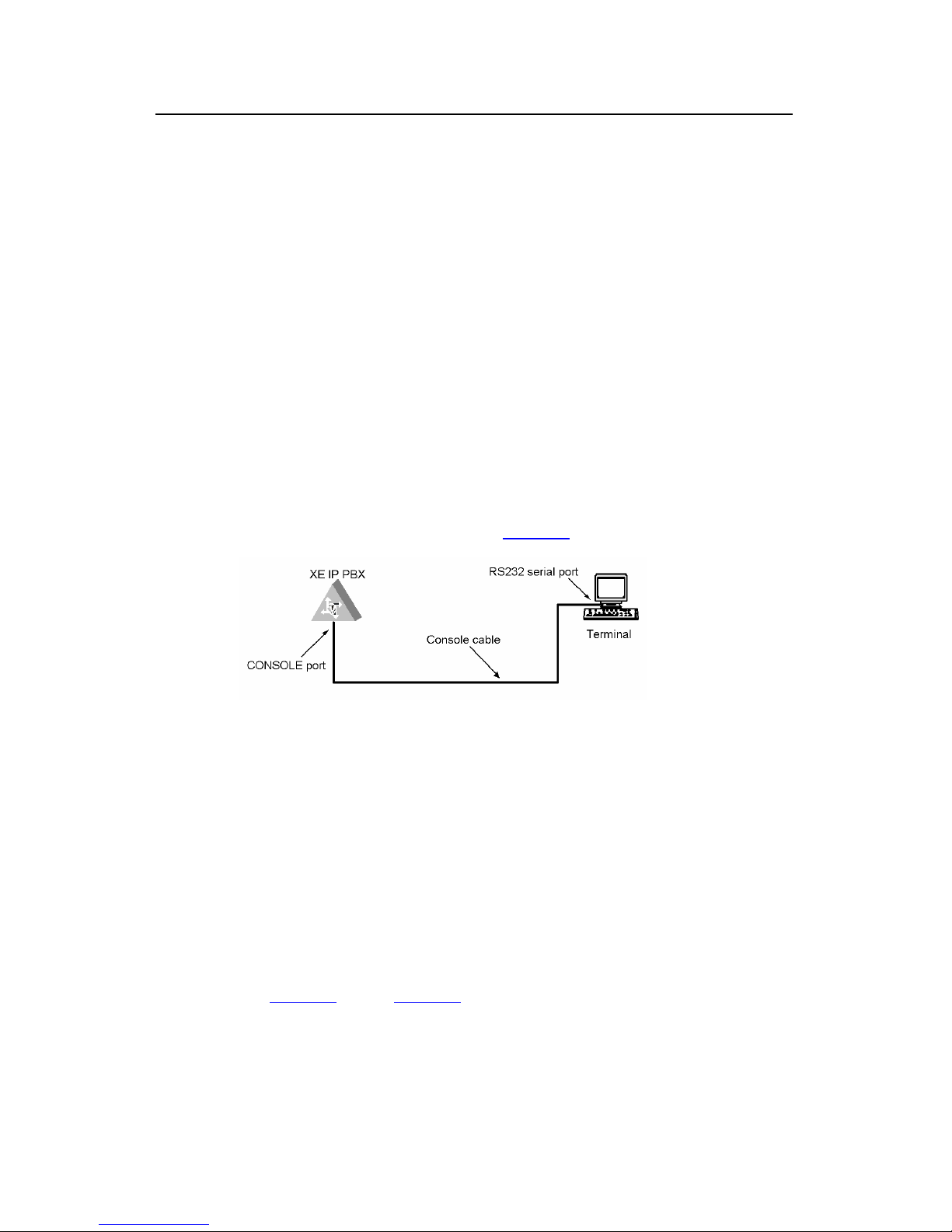
2.1.1 Configuring the XE IP PBX through the CONSOLE Port
Step 1: Connect the serial port on a PC (or terminal) to the CONSOLE port on the XE IP
PBX using a console cable, as shown in
Figure 2-1.
Figure 2-1 Set up a local configuration environment through the CONSOLE port
Step 2: Run the terminal emulation program (HyperTerminal of Win9X for example) on
the PC and set the terminal communications parameters as follows:
Bits per second: 9600 bps
Data bits: 8
Parity: None
Stop bits: 1
Flow control: None
Terminal emulation type: VT100
See
Figure 2-2 through Figure 2-4.
Page 12
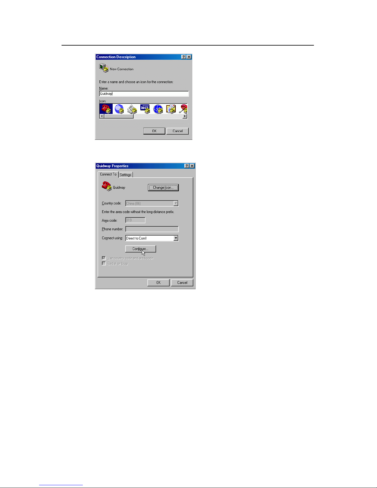
Operation Manual – Basic Configuration
H3C XE 200/2000 IP PBX Chapter 2 Command Line Interface for Configuration
2-2
Figure 2-2 Set up a new connection
Figure 2-3 Select the desired COM port
Page 13

Operation Manual – Basic Configuration
H3C XE 200/2000 IP PBX Chapter 2 Command Line Interface for Configuration
2-3
Figure 2-4 Port settings
Step 3: Power up the XE IP PBX. The system runs the power-on self-test (POST), and
then prompts you to press <Enter> until the command line prompt (<XE> for example)
appears.
Step 4: Enter commands to configure the XE IP PBX or view its running status. If you
need help, enter “?”. For more information about the commands, refer to the following
chapters.
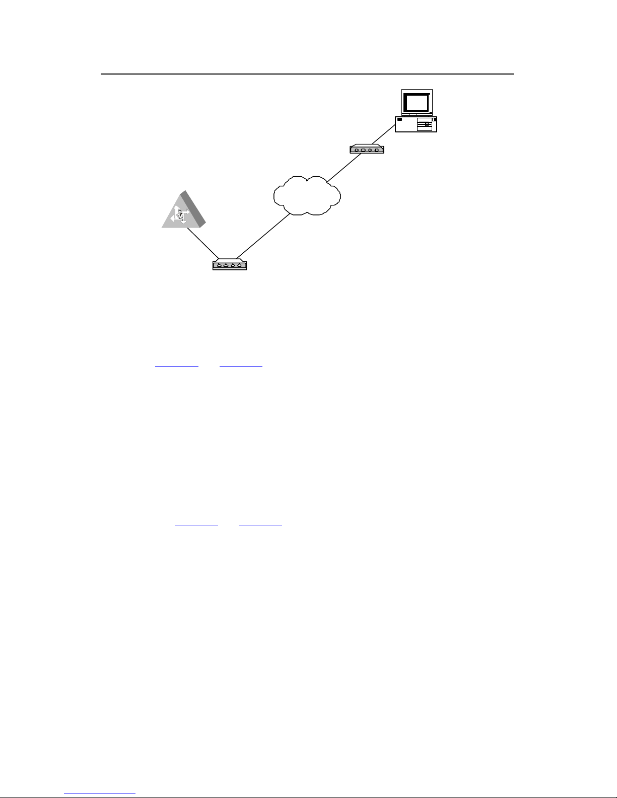
2.1.2 Configuring the XE IP PBX through the AUX Port
To configure the XE IP PBX through the AUX port, attach a modem to the serial port on
the PC and one to the AUX port on the XE IP PBX, as shown in
Figure 2-5.
Step 1: Attach a modem to the AUX port.
Page 14
Operation Manual – Basic Configuration
H3C XE 200/2000 IP PBX Chapter 2 Command Line Interface for Configuration
2-4
Telephone l ine
Serial port
AUX port
P C
Modem
Modem
XE IP PBX
Telephone line
PSTN
Figure 2-5 Set up a remote configuration environment
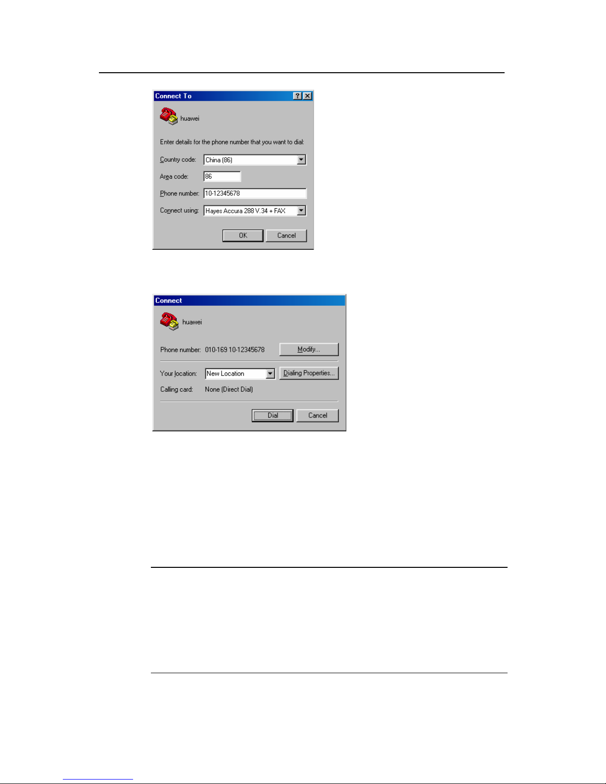
Step 2: Dial on the terminal to set up a connection to the XE IP PBX through the
terminal emulation program (such as HyperTerminal of Windows 9X), as shown in
Figure 2-6 and Figure 2-7. In the terminal emulation program, select the RS-232 serial
port of the PC to be used for connection, and set the terminal communications
parameters as follows:
Bits per second: 9600
Data bits: 8
Parity: None
Stop bits: 1
Flow control: None (or Hardware)
Terminal emulation type: VT100
See
Figure 2-3 and Figure 2-4.
Page 15
Operation Manual – Basic Configuration
H3C XE 200/2000 IP PBX Chapter 2 Command Line Interface for Configuration
2-5
Figure 2-6 Set the dialup number
Figure 2-7 Dial on the remote PC
Step 3: Enter the correct username and p assword, and proceed to configure or manage
the XE IP PBX when the command line prompt (<XE> for example) appears in the
remote terminal emulation program.
2.1.3 Configuring the XE IP PBX through Telnet
Note:
Before setting up a Telnet connection, make sure that:
z An IP address has been assigned to the XE IP PBX.
z VTY login authentication mode and the incoming and outgoing call restriction rules
have been configured.
z There is a reachable route between the console terminal and the XE IP PBX.
Page 16
Operation Manual – Basic Configuration
H3C XE 200/2000 IP PBX Chapter 2 Command Line Interface for Configuration
2-6
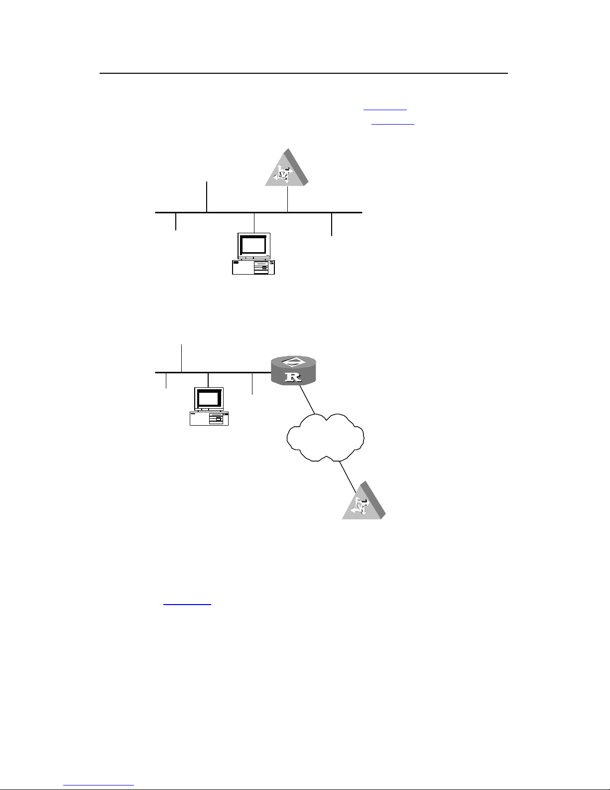
Step 1: If the PC and the XE IP PBX are located in the same LAN, connect the Et hernet
interfaces on them through the LAN, as shown in
Figure 2-8. Otherwise, connect the
PC to the XE IP PBX through the WAN, as shown in
Figure 2-9.
Telnet Client
PC
XE
LAN
Figure 2-8 Set up a Telnet configuration environment through the LAN
Teln et Client
LAN
PC
R outer
XE
WA
N
WAN
Figure 2-9 Set up a remote Telnet configuration environment through the WAN
Step 2: Run the Telnet program on the PC and set its terminal type to VT100, as shown
in
Figure 2-10.
Page 17

Operation Manual – Basic Configuration
H3C XE 200/2000 IP PBX Chapter 2 Command Line Interface for Configuration
2-7
Figure 2-10 Run the Telnet program
Step 3: Select [Connect\Remote system] in the Telnet window, and enter the IP address
of the Ethernet interface on the XE IP PBX in the dialog box as shown in
Figure 2-11.
Figure 2-11 Set up a Telnet connection with the XE IP PBX
Note:
Host Name in Figure 2-11 refers to the IP address of the XE IP PBX.
Step 4: After telnetting to the XE IP PBX, you are prompted for the username and
password. If the authentication is passed, the command line prompt (<XE > for example)
appears for you to configure the XE IP PBX or view its running status.
Note:
When you configure the XE IP PBX through telnet, be careful of modifying its IP
address as such modification may result in Telnet disconnection. If such modification is
required, you need to enter a new IP address of the IP BPX and make a new
connection.
Page 18

Operation Manual – Basic Configuration
H3C XE 200/2000 IP PBX Chapter 2 Command Line Interface for Configuration
2-8
2.2 Command Line Interface
The system provides a wide range of configuration commands and the command line
interface (CLI) through which you can configure and manage the XE IP PBX. The CLI
supports:
z Local configuration through the CONSOLE port.
z Remote configuration through the AUX port.
z Remote configuration through Telnet.
z Management of the configurations of terminal users in user interface view.
z Hierarchical command protection in which users can only execute the commands
commensurate with their levels.
z Local, password, and AAA authentication modes that safeguard the XE IP PBX
against intrusion of unauthorized users and guarantee system security.
z Easy access to on-line help by entering “?”.
z Commands such as tracert and ping to provide quick network test.
z Abundant debugging information for fault diagnosis.
z The telnet client function that allows you to telnet from the XE IP PBX to other
devices for management.
z FTP services that facilitate file upload and download.
z Ability to execute a previously executed command.
z Command line interpreter that provides multiple intelligent command parse
methods such as fuzzy match and context association for the convenience of
input.
Note:
You are not allowed to configure IDs or numbers that may conflict with command
keywords for XE IP PBX; otherwise, when any of the keywords including, without
limitation, active, all, allowable, callin, callout, config, h323, list, sip, subscriber and bind
is used, the system prompts error messages in the CLI.
2.2.1 Command Line View
The system commands implement the hierarchical protection model with four levels:
visit, monitor, system, and manage.
z Visit: Includes network diagnosis commands such as ping and tracert, and the
commands for accessing external devices, such as telnet and rlogin. No
commands at this level can be used to save the configuration files.
z Monitor: Provides the commands used for system maintenance and service fault
diagnosis, including the display and debugging commands. No commands at
this level can be used to save the configuration files.
Page 19

Operation Manual – Basic Configuration
H3C XE 200/2000 IP PBX Chapter 2 Command Line Interface for Configuration
2-9
z System: Includes routing and other service configuration commands that cover all
the layers of a network to provide direct network services for users.
z Manage: Includes the commands essential to system operations and support
modules. They are service support commands that involve file system, FTP, TFTP ,
configuration file switch, user management, level setting, as well as the parameter
setting within a system (the last case involves those non-protocol or non-RFC
specifications) commands.
Commensurate with the command levels, login users are divided into four levels,
namely that they can only use the commands at their own, or lower levels.
To prevent intrusion of unauthorized users, a user must undergo authentication when
switching to a higher level. In this case, the user must input the higher-level user
password, provided one has been set using the super password [ level user-level ]
{ simple | cipher } text command. Only when the correct password is provided can the
user switch to the higher level. Otherwise, the original user level remains unchanged.
Note:
For the sake of privacy, the system does not display the password that the user has
entered.
The user is allowed to make up to three attempts after an incorrect password input.
The command views are implemented according to different configuration
requirements. They provide different functions but are still related to each other. For
example, after setting up a connection with the XE IP PBX, you enter user view where
you can simply view the running status and statistics. By entering system-view in user
view, you go to the system view , where you can input dif ferent configuration commands
to enter the corresponding protocol, interface or functional module view.
Command lines are associated with the following command views:
z User view
z System view
z Interface views including GE interface view and virtual interface view .
z PS view
z LS view
z MS view
z MA view
z OverLoad Protection view
z GUI Server view
z User interface view
Table 2-1 shows the functionality of these command views and the commands for
entering them.
Page 20

Operation Manual – Basic Configuration
H3C XE 200/2000 IP PBX Chapter 2 Command Line Interface for Configuration
2-10
Table 2-1 Command view functionality
In command
view
To do… Prompt
Accessed by
entering the
command
Exit with the
command
User view
View brief
operating
information
and statistics
about the XE
IP PBX
<XE>
None (the
system
accesses user
view
immediately
after a
connection is
set up with the
XE IP PBX)
quit to
disconnect
from the XE IP
PBX
System view
Configure
system
parameters
[XE]
system-view
in user view
quit to return
to user view
User interface
view
Manage the
asynchronous
and logical
interfaces on
the XE IP PBX
[XE-ui0]
user-interfac
e 0 in system
view
quit to return
to the system
view
Interface view
Configure
interface
parameters
[XE-Ethernet1
/0]
interface
Ethernet 1/0
in system view
quit to return
to system view
PS view
Configure
process
server
[XE-ps]
process-serv
er in system
view
quit to return
to system view
LS view
Configure
location server
[XE-ls]
location-serv
er in system
view
quit to return
to system view
MS view
Configure
media server
[XE-ms]
media-server
in system view
quit to return
to system view
MA view
Configure
media ability
[XE-ma]
media-ability
in system view
quit to return
to system view
OverLoad
protection
view
Configure
overload
protection
[XE-olp]
overload-prot
ection in
system view
quit to return
to system view
GUI server
view
Configure GUI
server
[XE-gui]
gui in system
view
quit to return
to system view
Page 21

Operation Manual – Basic Configuration
H3C XE 200/2000 IP PBX Chapter 2 Command Line Interface for Configuration
2-11
Note:
The command line prompt uses IP PBX name as prefix (which defaults to H3C), view
name as suffix, a pair of parentheses to denote the current view, a pair of point brackets
(“<>”) to denote user view, and a pair of square brackets (“[ ]”) to denote system v iew or
any other configuration views.
2.2.2 Command Line Online Help
CLI offers the following online help types:
z Full help
z Fuzzy help
To obtain the desired help information, you can:
1) Enter “?” in any views, and you will obtain all the commands in this view and their
simple descriptions as well. For example, <XE> ?.
2) Enter a command and a “?” separated by a space, <XE> display ?. for example. If
"?" is at the position of a keyword, all the keywords and their brief descriptions are
shown.
3) Enter a command and a “?” separated by a space. If "?" is at the position of a
parameter, descriptions of these parameters are shown. For example:
[XE] interface ethernet ?
<0-0> Slot number
[XE] interface ethernet 0?
/
[XE] interface ethernet 0/?
<0-1>
[XE] interface ethernet 0/0 ?
<cr>
<cr> here indicates that no parameter is at this position. In this case, the command is
repeated in the next command line and executed if <Enter> is input.
4) Enter a character string followed by a “?”. All the commands starting with this
string are displayed. For example:
<XE> d?
debugging delete dir display
5) Enter a command followed by a character string and “?”. All the keywords starting
with this string are listed. For example:
<XE> display h?
history-command hotkey
Page 22

Operation Manual – Basic Configuration
H3C XE 200/2000 IP PBX Chapter 2 Command Line Interface for Configuration
2-12
6) Press <Tab> after entering the first several letters of a keyword to have the system
display the complete keyword. If more than one keyword has the same letters at
the front, press <Tab> repeatedly until the one that you need is displayed.
2.2.3 Command Line Error Information
The commands are executed only if they have no grammar error. Otherwise, error
information is reported, as shown in
Table 2-2.
Table 2-2 Common command line errors
Error information Cause
The command was not found.
Unrecognized command
The keyword was not found.
Parameter type error
Wrong parameter
Parameter value overflow
Incomplete command Incomplete command
Too many parameters Too many parameters
Ambiguous command Ambiguous parameters
2.2.4 History Command
With the function similar to Doskey , the CLI can automatically save previously executed
commands and repeat execution. By default, it saves up to ten history commands for
each user.
Table 2-3 lists the operations that a user can perform.
Table 2-3 Retrieve history commands
To do…
Enter the command or
press the key
Result
View history commands display history-comman d
Display the history
commands that the user
has entered and executed
successfully.
Retrieve the previous
history command
Up arrow key or <Ctrl+P>
Retrieve the previous
history command, if there
is any. Otherwise, the
system rings alarm.
Retrieve the next history
command
Down arrow key or
<Ctrl+N>
Retrieve the next history
command, if there is any.
Otherwise, the system
rings alarm.
Page 23

Operation Manual – Basic Configuration
H3C XE 200/2000 IP PBX Chapter 2 Command Line Interface for Configuration
2-13
Note:
The arrow keys can be used to retrieve history commands in Terminal and Telnet of
Windows 3.X. However, the up arrow key is invalid in the HyperTerminal of Windows
9X, because it is interpreted in a different way. In this case, you can use <Ctrl+P>
instead.
The display history-command command can only display the successfully executed
commands. An end user can use the up arrow key (or <Ctrl+P>) and the down arrow
key (or <Ctrl+N>) to display those commands.
2.2.5 Edit Features
The CLI provides the basic command editing features and suppo rts multi-line edit. The
maximum length of each command is 254 characters.
T able 2-4 shows these functions.
Table 2-4 Edit functions
Key Function
Common keys
If the edit buffer is not full, insert the character at
current cursor position and move the cursor to the
right. Otherwise, the alarm rings.
Backspace key
Delete the character to the left of the cursor and
move the cursor back. If the cursor gets to the
beginning of the command line, the alarm rings.
Left-arrow key or <Ctrl+B>
Move the cursor backward one character, and the
alarm rings when the cursor gets to the beginning
of the command line.
Right-arrow key or <Ctrl+F>
Move the cursor forward one character, and the
alarm rings when the cursor gets to end of the
command line.
Tab key
Press <Tab> after entering part of a keyword to get
fuzzy help. If finding a unique match, the system
substitutes the complete keyword for the
incomplete one and displays it on the next line. If
there are several matches, press <Tab>
repeatedly until the one that you need is displayed.
If a parameter has no match, your original input will
remain unchanged and be displayed again on the
next line after you press <Tab>.
2.2.6 Display Features
The CLI provides the following display features:
Page 24

Operation Manual – Basic Configuration
H3C XE 200/2000 IP PBX Chapter 2 Command Line Interface for Configuration
2-14
I. Pausing information display
When the information displayed exceeds one screen page, the display is paused. In
this case, three options shown in
Table 2-5 are available.
Table 2-5 Display functions
Key Function
<Ctrl+C> when information is being
displayed
Stop the display and the command
execution.
<Space> when information display pauses Continue to display the next screen.
<Enter> when information display pauses Continue to display the next line.
2.2.7 Regular Expressions
I. Introduction to regular expressions
Regular expressions are a powerful and flexible tool for pattern matching and
substitution. They are not restricted to a language or system and have been widely
accepted.
When using a regular expression, you need to construct a matching pattern according
to a certain rule, and then compare the matching pattern with the target object. The
simplest regular expressions exclude all metacharacte rs. For example, you can specify
a regular expression “hello”, which only matches the character string “hello”.
For flexible matching mode construction, regular expressions are allowed to contain
some special characters, called metacharacters, to define how other characters appear
in the target object. The following table d escribes the metacharacters.
Table 2-6 Metacharacters
Metacharacter Description
\ Escape character
. Matches any single character except for “\n”, including spaces.
!
The character to the left of the exclamation mark in the
expression should have no match or one match in the target
object.
*
The character to the left of the asterisk in the expression should
have no match or sequence of matches one after another in the
target object.
+
The character to the left of the plus sign in the expression should
have one match or sequence of matches one after another in the
target object.
Page 25

Operation Manual – Basic Configuration
H3C XE 200/2000 IP PBX Chapter 2 Command Line Interface for Configuration
2-15
Metacharacter Description
|
Allows either expression on the side of the alternation character
to match the target object.
^
The characters following the ^ sign must appear at the beginning
of the target object.
$
The characters before the dollar sign must appear at the end of
the target object.
(xyz)
The target object must contain the character string in the
parenthesis.
[xyz] Matches any character contained in the square brackets.
[^xyz]
Matches any character except for those contained in the square
brackets.
[a-z] Matches any character within the specified range.
[^a-z] Matches any character beyond the specified range.
{n}
The “n” in the brace brackets is a non-negative integer, indicating
that there are consecutive n matches for a character string.
{n,}
The “n” in the brace brackets is a non-negative integer, indicating
that there are consecutive n or more than n matches for a
character string.
{n,m}
The “m” and “n” in the brace brackets are non-negative intege rs,
with n<=m. It indicates that the consecutive matches are in the
range n to m. Note that no space is allowed on either side of the
comma.
For example:
^ip: to match the target object starting with the character string “ip”.
ip$: to match the target object ending with the character stri ng “ip”.
II. Usage of regular expressions
You can use regular expressions to filter out uninterested information when a large
amount of information is present.
1) Specify filtering mode between screens
If enormous information is present and output in multiple screens, you can filter
information after the prompt ”---- More ----” between screens appears by entering a
regular expression in one of the following forms:
z /regular-expression: to output all lines starting with the line that matches the
specified regular expression.
z -regular-expression: to output all lines that do not match the specified regular
expression.
Page 26

Operation Manual – Basic Configuration
H3C XE 200/2000 IP PBX Chapter 2 Command Line Interface for Configuration
2-16
z +regular-expression: to output only the lines that match the specified regular
expression.
For example, you can use the following command to view the current configuration
information:
<XE> display current-configuration
#
sysname XE2000
#
interface Aux0
async mode flow
#
interface GigabitEthernet0/0
ip address 192.168.80.50 255.255.255.0
#
interface GigabitEthernet0/1
#
interface NULL0
#
user-interface con 0
user-interface aux 0
user-interface vty 0 4
#
process-server
ps-config gkserver interface GigabitEthernet0/0
heartbeat password xe2000
start
#
gatekeeper
When the prompt “---- More ----” appears, you can manually enter a plus sign (+) and
then a regular expression to filter information to be displayed. To output only the lines
that contain the character string “gate”, for example:
---- More ---+interface (manually entered)
filtering...
gateway gw01
gateway gw02
<XE>
Page 27

Operation Manual – Basic Configuration
H3C XE 200/2000 IP PBX Chapter 2 Command Line Interface for Configuration
2-17
2.3 Hot Keys
2.3.1 Classifying Hot Keys
The hot keys in the system fall into two types: user-configurable and system.
The user-configurable hot keys include CTRL_G, CTRL_L, CTRL_O, CTRL_T and
CTRL_U. You can associate these hot keys with any commands for automatic
execution.
The system hot keys have fixed functions and do not allow customization, as shown in
Table 2-7.
Table 2-7 System hot keys
Keys or commands Function
CTRL_A Move the cursor to the beginning of current line
CTRL_B Move the cursor one character leftward
CTRL_C Terminate th e running function
CTRL_D Delete the character at the cursor
CTRL_E Move the cursor to the end of current line
CTRL_F Move the cursor one character rightward
CTRL_H Delete the character to the left of the cursor
CTRL_K Terminate the outbound connection
CTRL_N Display the next command in the history command buffer
CTRL_P
Display the previous command in the history command
buffer
CTRL_R Refresh the information of current line
CTRL_V Pasts the contents on the clipboard
CTRL_W Delete the word to the left of the cursor
CTRL_X Delete all the characters to the left of the cursor
CTRL_Y Delete all the characters to the right of the cursor
CTRL_Z Return to user view
CTRL_] Terminate or re-direct the inbound connection
ESC_B Move the cursor one word leftward
ESC_D Delete the word to the right of the cursor
ESC_F Move the cursor one word rightward
ESC_N Move the cu rsor downward to the next line
ESC_P Move the cursor upward to the previous line
Page 28

Operation Manual – Basic Configuration
H3C XE 200/2000 IP PBX Chapter 2 Command Line Interface for Configuration
2-18
Keys or commands Function
ESC_< Set the cursor’s location to the beginning of the clipboard
ESC_> Set the cursor’s location to the end of the clipboard
2.3.2 Usage of the Hot Keys
z You can press a hot key combination wherever you are allowed to enter a
command. Then the system displays the corresponding command as if you have
entered the complete command.
z If you have entered part of a command without pressing <Enter>, you can delete
the input characters and enter a complete command simply by pressing the hot
key for this new command.
z Similar to executing a command, after a shortcut key is executed, its
corresponding command prototype is retained in the history command buffer and
log for retrieving and locating problem.
Note:
The functionality of a hot key may be the user terminal dependent, for example, the hot
key assigned from the terminal may conflict with the one on XE IP PBX. In this case, the
application on the terminal responds to the hot key press.
Perform the following configuration in system view.
Table 2-8 Define hot keys
Operation Command
Define a hot key.
hotkey { CTRL_G | CTRL_L | CTRL_O
| CTRL_T | CTRL_U } command_text
Restore the default values in the system.
undo hotkey { CTRL_G | CTRL_L |
CTRL_O | CTRL_T | CTRL_U }
By default, the system assigns defaults to the hot keys of CTRL_G, CTRL_L and
CTRL_O as follows:
CTRL_G: display current-configuration
CTRL_L: display ip routing-table
CTRL_O: undo debugging all
Page 29

Operation Manual – Basic Configuration
H3C XE 200/2000 IP PBX Chapter 2 Command Line Interface for Configuration
2-19
The default values of the other hot keys are null by default.
Perform the following configuration in any view.
Table 2-9 Display the hot keys and their definitions
Operation Command
Display the hot keys and their functions.
display hotkey
2.3.3 Configuring Command Alias
The command alias configuration enables you to replace common Comware
commands by what command formats you prefer.
I. Enabling command alias
Perform the following configurations in system view .
Table 2-10 Enabling command alias
Operation Command
Enable command alias
enable command-alias
Disable command alias
undo enable command-alias
By default, the command alias function is disabled.
II. Specifying a command alias
Perform the following configuration in system view.
Table 2-11 Specifying a command alias
Operation Command
Specify a command alias
command-alias alias
currentfirstcmdkey
Cancel the configured command alias
undo command-alias alias
By default, no command alias is configured.
III. Displaying and Debugging
Perform the following configuration in any view.
Page 30

Operation Manual – Basic Configuration
H3C XE 200/2000 IP PBX Chapter 2 Command Line Interface for Configuration
2-20
Table 2-12 Displaying and Debugging
Operation Command
Display the current alias setting
display command-alias
Page 31

Operation Manual – Basic Configuration
H3C XE 200/2000 IP PBX Chapter 3 Basic Configuration
3-1
Chapter 3 Basic Configuration
3.1 Basic Configuration of Comware
I. Entering and exiting system view
After the XE IP PBX is powered on and you log into the XE IP PBX via the CONSOLE
port, the system displays user view with the prompt <H3C>. You can perform the
following operation to enter and exit system view.
Table 3-1 Enter and exit system view
Operation Command
Enter system view from user view
system-view
Returning to the view of an upper level
quit
Return to user view
return
Use the quit command to return to an upper level view . If you are in user view, you can
use this command to exit the system. You can also run the return command by
pressing <Ctrl+Z>.
II. Setting the name for an XE IP PBX
The name of an IP PBX appears in command prompt. You can change it if necessary.
Perform the following configuration in system view.
Table 3-2 Set the name of an XE IP PBX
Operation Command
Set the name of an XE IP PBX
sysname sysname
III. Setting system clock
You must set system clock to the correct time in order to work with other devices
properly.
Perform the following configuration in user view.
Page 32

Operation Manual – Basic Configuration
H3C XE 200/2000 IP PBX Chapter 3 Basic Configuration
3-2
Table 3-3 Set system clock
Operation Command
Set standard time
clock datetime HH:MM:SS
YYYY/MM/DD
Set time zone
clock timezone time-zone-name { add |
minus } HH:MM:SS
Remove the setting of time zone
undo clock timezone
Set daylight saving time
clock summer-time
summer-time-zone-name { one-off |
repeating } start-time start-date
end-time end-date add-time
Remove the setting of daylight saving
time
undo clock summer-time
Caution:
Be cautious to modify the system clock, which requires shutdown of the LS when the
system is running.
IV. Setting the banner text
The banner text is a message that the system displays after connecting to the XE IP
PBX, login authentication, and interactive configuration.
Perform the following configuration in system view.
Table 3-4 Set banner text
Operation Command
Set the banner text that will be displayed
when entering terminal user interface
header incoming text
Set the banner text that will be displayed
during authentication
header login text
Set the banner text that will displayed upon
configuration
header shell text
Remove the banner text that has been set
undo header { incoming | login |
shell }
Page 33

Operation Manual – Basic Configuration
H3C XE 200/2000 IP PBX Chapter 3 Basic Configuration
3-3
V. Setting the password used for switching the user level
If you log in as a user with a lower level and want to switch to a higher level, you need to
enter the password of a higher level, which should be set previously.
Perform the following configuration in system view.
Table 3-5 Set the password used for switching the user level
Operation Command
Set the password used for switching the
user level
super password [ level user-level ]
{ simple | cipher } password
Remove the password that has been set
undo super password [ level
user-level ]
VI. Switching user level
To switch to a higher user level, you must enter a corresponding password.
Perform the following configuration in user view.
Table 3-6 Switch user level
Operation Command
Switch user level super [ level ]
VII. Locking user interface
When you are temporarily leaving, to prevent unauthorized access to the terminal
interface, you can lock user interface. You must enter and confirm a password to lock
user interface. To unlock and enter the user interface again, you must provide the
correct password.
Perform the following configuration in user view.
Table 3-7 Lock user interface
Operation Command
Lock user interface
lock
VIII. Setting the command level
All commands fall into four levels, which are visit, monitor, system, and manage, whos e
identifier ranges from 0 to 3. Administrators can assign the level of a command and the
view it belongs to as needed.
Perform the following configuration in system view.
Page 34

Operation Manual – Basic Configuration
H3C XE 200/2000 IP PBX Chapter 3 Basic Configuration
3-4
Table 3-8 Set command privilege
Operation Command
Set command privilege in a view
command-privilege level level view
view command-key
Reset the default command privilege
undo command-privilege view view
command-key
Table 3-9 Default command privilege
Code Level Command
0 Visit ping, tracert, telnet
1 Monitor display, debugging
2 System
All configuration commands except for those of
manage level
3 Manage
File System commands, FTP commands, and TFTP
commands
Note:
Each command belongs to its default view and has corresponding privilege; therefore it
is not necessary to reset them.
IX. Displaying system status information
Use the display command to collect system status i nformation, which can be cla ssified
as follows:
z Commands that display system configuration information
z Commands that display the status of system operation
z Commands that display system statistics
For the details of the display command of various protocols and interfaces, refer to
corresponding chapters. The table below lists some system-related display
commands.
Perform the following configuration in any view.
Page 35

Operation Manual – Basic Configuration
H3C XE 200/2000 IP PBX Chapter 3 Basic Configuration
3-5
Table 3-10 Display system status information
Operation Command
Display system version
display version
Display system clock
display clock
Display terminal user display users [ all ]
Display the saved configuration display saved-configuration
Display current configuration display current-configuration
Display debugging status
display debugging [ interface
{ interface-type interface-number |
interface-name } ] [ module-name ]
Display operating configuration of the
current view
display this
Display diagnostic information display diagnostic-information
Display the contents on clipboard
display clipboard
Display the statistics about CPU usage
display cpu-usage-for-user
[ configuration | number [ offset ]
[ verbose ] [ from-device ] ]
When troubleshooting or daily maintenance is required, a lot of information should be
collected. But there are multiple display commands and it is difficult to collect all
information needed by running one command. You can run the display
diagnostic-information command to collect the current running information of each
module of the system.
The display diagnostic-information command can list the information displayed after
running the following commands: display clock, display version, vrbd, display
interface, display current-configuration, display saved-configuration, display ip
interface, display ip statistics, display exception 10, display exception 3
verbose , display logbuffer, display history all, etc.
3.2 Ethernet Interface Configuration
3.2.1 Introduction to the Ethernet Interface
I. Types of Ethernet interface
An XE 200 IP PBX has two fast Ethernet (FE) interfaces (electrical) compliant with
100Base-TX physical layer specification; while an XE 2000 has two Gigabit Ethernet
(GE) interfaces, one is 1000Base-TX-compliant GE electrical interface and the other is
1000Base-LX and 1000Base-SX-compliant GE optical interface.
Page 36

Operation Manual – Basic Configuration
H3C XE 200/2000 IP PBX Chapter 3 Basic Configuration
3-6
II. Speed and duplex mode
The FE electrical interface operates at a speed of 10 Mbps or 100 Mbps, and GE
electrical interface at a speed of 10 Mbps, 100 Mbps or 1000 Mbps.
Both FE electrical interface and GE electrical interface support half-duplex and
full-duplex modes.
To simplify the configuration and management, both FE electrical interface and GE
electrical interface can operate in auto-negotiation mode to negotiate with other
network devices to determine the most suitable mode and transmission spe ed.
Optical interface can only operate in full-duplex mode, and its transmission speed
cannot be changed via configuration. GE optical interface can only operate at a speed
of 1000 Mbps. The operating mode of the optical interface connecting the XE IP PBX to
a network can be aggressive or auto-negotiate, but it must be the same as that of the
peer interface.
III. Frame format supported
Both FE and GE Ethernet interface can receive and recognize the Ethernet frame with
frame format of Ethernet_II or Ethernet_SNAP, and send frames in Ethernet_II format.
3.2.2 Configuring the Ethernet Interface
Ethernet interface configuration tasks are described in the following sections:
z Entering the specified Ethernet interface view
z Setting the IP address of the interface
z Setting MTU
z Choosing speed
z Choosing operating mode
z Enabling/disabling local loopback
You should configure FE interface in Ethernet interface view and GE interface in GE
interface view. Every configuration parameter has a default value, so, generally, you
need only to configure the IP address to make the system operate normally in most
cases.
I. Entering the specified Ethernet interface view
Perform the following configuration in system view.
Table 3-11 Enter the view of specified Ethernet interface
Operation Command
Enter FE interface view
interface ethernet number
Enter GE interface view
interface GigabitEthernet number
Page 37

Operation Manual – Basic Configuration
H3C XE 200/2000 IP PBX Chapter 3 Basic Configuration
3-7
II. Setting the IP address of the interface
Perform the following configuration in Ethernet interface view.
Table 3-12 Set the IP address of the interface
Operation Command
Set the IP address of the interface
ip address ip-address mask
Remove the IP address of the interface undo ip address [ ip-address mask ]
III. Setting MTU
The parameter of maximum transmission unit (MTU) affects the fragmentation and
reassembly of IP packets.
Perform the following configuration in Ethernet interface view.
Table 3-13 Set MTU
Operation Command
Set MTU
mtu size
Restore to the default value
undo mtu
By default, the MTU is in Ethernet_II frame format. The MTU size ranges from 46 to
1500 bytes for FE interface, and 46 to 16384 bytes for GE interface.
IV. Choosing speed
An Ethernet interface can operate at multiple speeds. FE interface can operate at 10
Mbps and 100 Mbps, and GE electrical interface at 10 Mbps, 100 Mbps, and 1000
Mbps.
Perform the following configuration in Ethernet interface view.
Table 3-14 Choose transmission speed
Operation Command
Choose the transmission speed of an
Ethernet interface
speed { 10 | 100 | 1000 | negotiation }
The default is negotiation, which means the system automatically negotiates the
optimal speed. You can also specify a speed which must be equal to the actual speed
of the network.
Page 38

Operation Manual – Basic Configuration
H3C XE 200/2000 IP PBX Chapter 3 Basic Configuration
3-8
V. Choosing operating mode
As previously mentioned, the Ethernet interface can operate in full and half duplex
modes. The Ethernet interface of an XE IP PBX must operate in half duplex mode when
connected to a Hub and full duplex mode when connected to a switched Ethernet
switch. Perform the following configuration in Ethernet interface view.
Table 3-15 Choose the operating mode
Operation Command
Choose the operating mode of an
Ethernet interface
duplex { negotiation | full | half }
The default is negotiation, which means the system automatically negotiates the
optimal operating mode.
VI. Enabling/disabling local loopback
You may need to enable the local loopback when testing some spe cial functions of the
Ethernet interface.
Perform the following configuration in the Ethernet interface view.
Table 3-16 Enable/disable local loopback
Operation Command
Enable local loopback
loopback
Disable local loopback
undo loopback
By default, loopback is disabled.
VII. Configuring the operating mode of an Ethernet interface
When the Ethernet interface operates in the promiscuous mode, it receives all correct
Ethernet packets without checking their MAC addresses. This mod e is applied to traf fic
monitoring on the network.
Perform the following configuration in Ethernet interface view.
Table 3-17 Configure the operating mode of the Ethernet interface
Operation Command
Enable the Ethernet interface to operate
in the promiscuous mode.
promiscuous
Disable the Ethernet interface from
operating in the promiscuous mode.
undo promiscuous
Page 39

Operation Manual – Basic Configuration
H3C XE 200/2000 IP PBX Chapter 3 Basic Configuration
3-9
By default, the Ethernet interface operates in the non-promiscuous mode.
3.2.3 Displaying and Debugging Ethernet Interface
Perform the following configuration in any view.
Table 3-18 Display the status of a specified Ethernet interface
Operation Command
Display the status of a specified
Ethernet interface
display interfaces ethernet number
3.3 Static Route Configuration
The configuration of static route includes:
z Configuring a static route
z Configuring a default route
z Configuring static route privileges
z Deleting a static route
3.3.1 Introduction to the Static Route
Static routes are routes which the administrator configures manually. Through the
configuration of static routes, you can build an interconnected network. Each static
route has one of the following properties, so there are three kinds of routes:
z Reachable route: which is the case for common routes, that is, IP packet s are sent
to the next hop along the route marked by the destination.
z Destination unreachable route: When a static route to a destination has the
property of reject, any IP packet bound for it will be discarded, and the source will
be informed that the destination is unreachable.
z Blackhole route: When a static route to a destination has the property of
blackhole, any IP packet bound for it will be discarded, and the source will not be
informed.
Among the properties, the reject and blackhole are commonly used to control the
range of destination that the XE IP PBX can reach and can help troubleshoot the
network.
3.3.2 Introduction to the Default Route
The default route is a special case of static route, which is used when no matched route
is found. In a routing table, a default route has a routing address/mask pair of
0.0.0.0/0.0.0.0. You can view the destination of a default route by running the display
ip routing-table command.
Page 40

Operation Manual – Basic Configuration
H3C XE 200/2000 IP PBX Chapter 3 Basic Configuration
3-10
If the destination address of a packet does not match any route, the default route will be
used to forward this packet. If the default route does not exist and the destination of the
packet is not in routing table, the packet will be discarded, and an ICMP destination
unreachable message will be returned.
3.3.3 Configuring a Static Route
Perform the following configuration in system view.
Table 3-19 Configure static route
Operation Command
Add a static route
ip route-static ip-address { mask | mask-length }
{ interface-name | nexthop-address } [ preference
preference-value ] [ reject | blackhole ]
Delete a static route
undo ip route-static ip-address { mask |
mask-length } [ interface-name | nexthop-address ]
[ preference preference-value ]
3.3.4 Configuring a Default Route
Perform the following configuration in system view.
Table 3-20 Configure a default route
Operation Command
Configure a default route
ip route-static 0.0.0.0 { 0.0.0.0 | 0 } {interface-name |
nexthop-address } [ preference value ] [ reject |
blackhole ]
Delete a default route
undo ip route-static 0.0.0.0 { 0.0.0.0 | 0 }
[interface-name | nexthop-address] [ preference
value | reject | blackhole ]
3.3.5 Deleting all Static Routes
Perform the following configuration in system view.
Table 3-21 Delete all static routes
Operation Command
Delete all static routes delete static-routes all
You can delete all configured static routes by running this command, including the
default route.
Page 41

Operation Manual – Basic Configuration
H3C XE 200/2000 IP PBX Chapter 3 Basic Configuration
3-11
3.3.6 Displaying and Debugging Routing Table
After the previous configuration, you can view the information of the configured static
route in any views by running the display command to verify the configuration.
Perform the following configuration in system view.
Table 3-22 Display and debug routing table
Operation Command
View the routing table summary display ip routing-table
Page 42

Process Server Configuration
Page 43

Operation Manual – Process Server Configuration
H3C XE 200/2000 IP PBX Table of Contents
i
Table of Contents
Chapter 1 Process Server Overview............................................................................................1-1
1.1 Introduction to Process Server .......................................................................................... 1-1
1.2 PS Capacities .................................................................................................................... 1-2
Chapter 2 H.323 Overview............................................................................................................2-1
2.1 Introduction to H.323 Protocol...........................................................................................2-1
2.1.1 Terms......................................................................................................................2-1
2.1.2 H.323 Architecture ..................................................................................................2-5
2.1.3 H.323 Operating Fundamentals..............................................................................2-6
2.2 Functionality and Features of H.323 Gatekeeper..............................................................2-9
2.2.1 Registration Management....................................................................................... 2-9
Chapter 3 Gatekeeper Configuration...........................................................................................3-1
3.1 Introduction to Gatekeeper Configuration.......................................................................... 3-1
3.2 Basic Gatekeeper Configuration........................................................................................ 3-1
3.3 Advanced Gatekeeper Configuration.................................................................................3-5
Chapter 4 SIP Overview................................................................................................................4-1
4.1 Introduction to SIP ............................................................................................................. 4-1
4.1.1 Terms......................................................................................................................4-1
4.1.2 Functionality and Features of SIP........................................................................... 4-3
4.1.3 SIP Fundamentals................................................................................................... 4-4
4.1.4 SIP Messages.........................................................................................................4-6
4.2 Functionality and Features of SIP Server..........................................................................4-7
4.2.1 SIP Proxy Server..................................................................................................... 4-7
4.2.2 LS............................................................................................................................ 4-9
4.2.3 SIP Registrar........................................................................................................... 4-9
4.2.4 SIP Redirect Server ..............................................................................................4-10
Chapter 5 SIP Server Configuration............................................................................................5-1
5.1 SIP Proxy Server Configuration.........................................................................................5-1
5.1.1 Introduction to SIP Proxy Server.............................................................................5-1
5.1.2 Basic SIP Proxy Server Configuration .................................................................... 5-1
5.1.3 Advanced SIP Proxy Server Configuration............................................................. 5-4
5.2 LS Configuration................................................................................................................5-6
5.2.1 Introduction to LS....................................................................................................5-6
5.2.2 Configuring the LS ..................................................................................................5-7
5.3 SIP Registrar Configuration............................................................................................... 5-7
5.3.1 Introduction to SIP Registrar................................................................................... 5-7
5.3.2 Configuring the SIP Registrar ................................................................................. 5-7
Page 44

Operation Manual – Process Server Configuration
H3C XE 200/2000 IP PBX Table of Contents
ii
5.4 SIP Redirect Server Configuration.....................................................................................5-7
5.4.1 Introduction to SIP Redirect Server.........................................................................5-7
5.4.2 Configuring SIP Redirect Server............................................................................. 5-7
Chapter 6 Displaying and Debugging the PS............................................................................. 6-1
6.1 Displaying Information for the PS......................................................................................6-1
6.2 Debugging the PS.............................................................................................................. 6-2
Page 45

Operation Manual – Process Server Configuration
H3C XE 200/2000 IP PBX Chapter 1 Process Server Overview
1-1
Chapter 1 Process Server Overview
1.1 Introduction to Process Server
The H3C XE 200/2000 IP PBX (hereinafter referred to as XE IP PBX) supports both
session initiation protocol (SIP) and H.323 protocol, and thus is suitable for complex
networks deployed with both SIP and H.323 devices.
An XE IP PBX can serve as a location server (LS), a process server (PS) and/or a
media server. This module mainly describes how to co nfigure an XE IP PBX functioning
as a PS.
A PS provides the function of an H.323 gatekeeper a nd/or a SIP Server , depen d ing on
your configuration.
Figure 1-1 shows the architecture of the XE IP PBX.
Figure 1-1 Architecture of the XE IP PBXs
Configure an XE IP PBX as follows depending on the network where the IP PBX is
deployed:
z In a SIP network, enable SIP Server on the PS, and set gateway device type to
SIP user agent (UA) on the LS.
z In an H.323 network, enable gatekeeper on the PS, and set gateway device type
to H.323 on the LS.
z In a complex network deployed with both SIP and H.323 devices, enable SIP
server and gatekeeper on the PS, and set the proper gateway device type on the
LS.
For the configuration of LS, refer to the “LS Configuration” part of this manual.
Page 46

Operation Manual – Process Server Configuration
H3C XE 200/2000 IP PBX Chapter 1 Process Server Overview
1-2
1.2 PS Capacities
The following table describes the capacities of XE 200/2000 IP PBXs.
Table 1-1 Capacities of the XE 200/2000 IP PBXs
Item XE 200 XE 2000
Max. concurrent online gateway
devices
400 4000
Max. subscriber numbers 400 4000
Max. maintained calls 400 4000
Min. call ability per second (CAPS) 1 5
Page 47

Operation Manual – Process Server Configuration
H3C XE 200/2000 IP PBX Chapter 2 H.323 Overview
2-1
Chapter 2 H.323 Overview
2.1 Introduction to H.323 Protocol
H.323, packet-based multimedia communications system, is a standard that specifies
the components, protocols, and procedures that provide multimedia communication
services over packet networks. It has long been used by traditional carriers and
network device manufacturers in their V oIP solutions. Now, it is one of the standards for
VoIP.
The H.323 protocol suite is specified for LANs that provide non-guaranteed quality of
service (QoS) and is implemented at the application layer. It includes protocols such as
H.225.0, H.245, G.729, G.723.1, G.711, H.261, H.263, and T.120 series. Among them,
G.723.1, G.729, and G.711 are audio codec protocols; H.263 and H.261 are video
codec protocols; H.225.0 and H.245 are system control protocols; and T.120 series are
multimedia data transmission protocols.
The real-time transport protocol (RTP) provides end-to-end real-time audio and video
delivery services. Its functionality is enhanced through its control protocol, the RTP
control protocol (RTCP). The primary function of RTCP is to provide feedback on the
quality of data distribution, which allows the application system to accommodate to
different network conditions and helps with fault isolation as well. These two protocols
work together to ensure real-time voice transmission.
H.323 applies to initiate sessions. It sets up and terminates a multimedia session
involving a group of participants, and dynamically adjusts and modifies session
characteristics such as required media type (voice or video), media enco ding/decoding
format, and multicast/unicast.
H.323 adopts the Client/Server model and sets up user calls through communication
between gateway and gatekeeper.
2.1.1 Terms
I. H.323 terminal
The H.323 terminals are communication devices of terminal users. They must support
at least one audio coding format in the H.323 protocol suite. They can also optionally
support video coding formats.
II. H.323 gateway
H.323 gateways are responsible for the signaling conversions between different
signaling protocols and the information conversions between different media formats.
Page 48

Operation Manual – Process Server Configuration
H3C XE 200/2000 IP PBX Chapter 2 H.323 Overview
2-2
They allow PSTN terminals and H.323 terminals to communicate with each other
transparently.
III. H.323 gatekeeper
H.323 gatekeepers are optional to an H.323 network. They function to manage H.323
network by providing endpoints services such as network access control, call routing
control, and address translation.
IV. H.323 signaling
H.323 protocol suite contains the following three types of signaling:
z RAS signaling. This type of signaling is used between H.323 gateways and H.323
gatekeepers for operations such as gatekeeper discovery, gateway
registration/unregistration, call access permission, and call release. In a voice
network that contains gatekeepers, RAS signaling channels exist between voice
gateways and gatekeepers. They are established prior to other channels and are
independent of the call control channels and the media control channels. RAS
signaling exchange is necessary for both direct and gatekeeper rout ed call modes.
A RAS channel is an unreliable channel.
z H.225.0 call control signaling. This type of signaling is used to set up call
connections between H.323 gateways or between H.323 gateways and
gatekeepers. In a voice network that contains no gatekeepers, a call control
signaling channel is established between the calling gateway and the called
gateway. In a voice network that contains gatekeepers, if the call is set up in direct
call mode, the calling gateway obtains the call address of the called gateway
through RAS signaling exchange, and the call control signaling channel is
established between the calling gateway and the called gateway. Whereas if the
call is setup in routed call mode, the call control signaling channel is established
between the gateway and the gatekeeper. A call control signaling channel is
independent of the RAS channel and H.245 media control channel. It is a reliable
channel.
z H.245 media channel control signaling. This type of signaling is used to establish
multimedia channels (RTP [real time protocol]/RTCP [RTP control protocol]
channels) between calling gateways and called gateways. The procedure to
establish a multimedia channel contains sub-procedures such as master-slave
determination, capability exchange, and opening logical channels. In this
procedure, the calling and called gateways exchange multimedia information such
as the information about the channel ports and the coding/decoding methods of
them.
In a voice network that contains no gatekeepers, the H.245 media channel control
signaling channel is established between the calling gateway and the called gateway.
The calling gateway obtains the H.245 signaling address of the calle d gateway through
H.225.0 call control signaling. In a voice network that contains gatekeepers, if the call is
Page 49

Operation Manual – Process Server Configuration
H3C XE 200/2000 IP PBX Chapter 2 H.323 Overview
2-3
set up in direct call mode, the H.245 media channel control signaling channel is
established between the calling gateway and the called gateway. Whereas if the call is
set up in routed call mode, the H.245 media channel control signaling channel is
established between the gateway and the gatekeeper.
An H.245 media control signaling channel is independent of the RAS channel and the
H.225.0 call control signaling channel. It is a reliable channel.
V. H.323 call modes
For networks containing gatekeepers, the H.323 call mode refers to the way to transmit
call control signaling and H.245 media channel control signaling. H.323 protocol suite
defines two call modes: direct call and routed call.
z Direct call
XE IP PBX
(Gatekeeper)
H. 32 3 Gat eway
H.3 23 Ga teway
RA S Sign al RA S Signal
H.225. 0 Signal
H.245 Signal
Figure 2-1 H.323 direct call
The process of a direct call is as follows.
1) The calling gateway gets authenticated at the gatekeeper through RAS signaling
exchange. It then obtains the call signaling address of the call ed gateway from the
gatekeeper if it passes the authentication.
2) The calling gateway establishes a call control channel between itself and the
called gateway using the call signaling address. Through this channel, the calling
gateway communicates with the called gateway with call control signaling to
exchange H.245 address information.
3) The calling gateway and the called gateway establish media control channel usi ng
the H.245 address information they obtain to exchange multimedia channel
information.
In direct call mode, call control signaling and media channel control signaling are
exchanged between the calling gateway and the called gateway directly rather than
through the gatekeeper.
z Routed call
Page 50

Operation Manual – Process Server Configuration
H3C XE 200/2000 IP PBX Chapter 2 H.323 Overview
2-4
XE IP PB X
(Gatekeeper)
RAS Signal
RAS Signal
H.225.0 S i gnal
H.245 S i gnal
H.225.0 S i gnal
H.245 Si gnal
H.323 GatewayH.323 Gateway
Figure 2-2 Routed call
The process of a routed call is as follows.
1) The calling gateway gets authenticated at the gatekeeper through RAS signaling.
It then obtains the call signaling address of the gatekeeper if it passes the
authentication.
2) The calling gateway establishes a call control channel between itself and the
gatekeeper using the call signaling address.
3) The gatekeeper establishes a call control channel between itself and the called
gateway. The calling gateway then sends a call setup request to the called
gateway through the gatekeeper.
4) The called gateway gets authenticated at the gatekeeper through RAS signaling.
5) The calling gateway and the called gateway exchange call control signaling
through the gatekeeper . This procedure varies in the following ways:
If the gatekeeper gets the H.245 address of the calling gate way during the exchange of
call control signaling:
z The gatekeeper opens a H.245 port and notifies the called gateway.
z The called gateway actively establishes a media channel control signaling channel
between itself and the gatekeeper.
z The gatekeeper establishes a media channel control signaling channel between
itself and the calling gateway.
z The calling gateway and the called gateway exchange media channel control
signaling and multimedia information through the gatekeeper.
If the gatekeeper gets the H.245 address of the called gateway during the exchange of
call control signaling:
z The gatekeeper opens a H.245 port and notifies the calling gateway.
z The calling gateway establishes a media channel control signaling channel
between itself and the gatekeeper.
z The gatekeeper establishes a media channel control signaling channel between
itself and the called gateway.
z The calling gateway and the called gateway exchange media channel control
signaling and multimedia information through the gatekeeper.
In this mode, the calling gateway and the called gateway exchange the call control
signaling and the media channel control signaling through the gatek eeper.
Page 51

Operation Manual – Process Server Configuration
H3C XE 200/2000 IP PBX Chapter 2 H.323 Overview
2-5
VI. H.323 call setup modes
Based on the exchange method of multimedia information, such as the RTP/RTCP
transmission address), H.323 calls can be set up in common mode or fast start mode.
z Common: Multimedia channel information is transferred through the multimedia
control signaling channel. In this mode, H.245 processes including master/slave
gateway decision, capability negotiation and logical channel opening are involved.
z Faststart: Multimedia channel information is transferred through the call control
signaling channel by the fastStart parameter in the call control signaling. In this
mode, H.245 processes including master/slave gateway, capability negotiation
and logical channel opening are not involved.
2.1.2 H.323 Architecture
The architecture of H.323 includes terminals, gateways, gatekeepers and multipoint
control units (MCUs). Gatekeepers are optional in an H.323 network; but if a
gatekeeper is present, the terminals, gateways, and MCUs registered with the
gatekeeper form a zone (see
Figure 2-3). These devices can overlay networks or
subnets through routers.
A zone is inde pendent of network topology. It may comprise multiple network segments
connected using routing devices. Multiple zones form an H.323 system.
MCUs are applied mainly in VoIP networks that provides voice conferencing functions.
A MCU consists of a multipoint controller (MC) and a multipoint processor (MP). In
multipoint conferencing, the MC is in responsible for capability exchange with
endpoints, and the MP processes media streams (including audio/video/data streams
from terminals) and then forwarded them to the destination.
H. 323 t erm inal
H.323 t erm inal
H. 323 t erm inal
H. 323 t erminal H. 323 termi nal
Gatekeeper
Router Rout er
H.323 gat eway
MCU
H. 323 t erm inal
H.323 t erm inal
H. 323 t erm inal
H. 323 t erminal H. 323 termi nal
Gatekeeper
Router Rout er
H.323 gat eway
MCU
Figure 2-3 H.323 zone
Page 52

Operation Manual – Process Server Configuration
H3C XE 200/2000 IP PBX Chapter 2 H.323 Overview
2-6
2.1.3 H.323 Operating Fundamentals
I. Gatekeeper discovery
Gatekeeper discovery refers to the process that an endpoint looks for a gateway ready
to serve and control it. RAS signaling is used betwee n endpoint s and gatekeepers. The
endpoint unicasts or multicasts a Gatekeeper Request (GRQ) message and the
gatekeeper or gatekeepers respond with a Gatekeeper Confirm (GCF) or Gatekeeper
Reject (GRJ).
II. Registration
If an endpoint sends a registration request (RRQ) message to a discovered or static
gatekeeper for joining the zone the gatekeeper governs, it may receive a registration
confirm (RCF) or registration reject (RRJ) message to accept or reject the registration
request.
After registration, either side can ask for canceling registration by sending an
Unregistration Request (URQ) message. However, whether to cancel registration is up
to the gatekeeper: the endpoint can only respond with an Unregistration Confirm (UCF)
message to cancel registration.
III. Address translation
If the calling endpoint knows the alias of the called endpoint but not the call signaling
address, it sends a Location Request (LRQ) message to the gatekeeper.
IV. Access control
If the address of the called endpoint is available, the calling endpoint sends an
Admissions Request (ARQ) message, based on which the gatekeeper decides
whether to allow this endpoint to join a call process. This is how the gatekeeper controls
admission. In the ARQ message sent to the gatekeeper, the calling endpoint may ask
for direct call signaling (see
Figure 2-4) or gatekeeper-routed call signaling (see Figure
2-5). Which method is used however, is decided by the gatekeeper in the Admissions
Confirm (ACF) message.
Page 53

Operation Manual – Process Server Configuration
H3C XE 200/2000 IP PBX Chapter 2 H.323 Overview
2-7
Endpoint 1 GateKeeper 1 Endpoint 2
ARQ(1)
ACF/ARJ(2)
Setup(3)
Call proceeding(4)
ARQ(5)
ACF/ARJ(6)
Alerting(7)
Connect(8)
RAS Messages
Call Signalling Messages
Figure 2-4 Direct call signaling between endpoints
Endpoint 1 GateKeeper 1 Endpoint 2
ARQ(1)
ACF/ARJ(2)
Setup(3)
Cal l pro c eed in g(6 )
ARQ(7)
ACF/ARJ(8)
A ler ting(9)
Conn ec t(1 1)
RAS Messages
Call Signalling Messages
Se tup (5)
Ca ll proc ee din g( 4)
A lerting( 10 )
Conn ec t(1 2)
Figure 2-5 Gatekeeper-routed call signaling
V. Call setup
When the calling endpoint receives the ACF message from the gate keeper , it sends call
signaling to request a call. In a direct call signaling, for example, the calling endpoint
first sends a call setup signaling message (setup) to the called endpoint, reque sting for
a connection.
Page 54

Operation Manual – Process Server Configuration
H3C XE 200/2000 IP PBX Chapter 2 H.323 Overview
2-8
VI. Call proceeding
When the called endpoint receives the setup message, it responds with a call
proceeding message, indicating the request is being processed. It may choose not to
send this message however.
VII. Alerting
Then the called endpoints may send an alerting message to the calling endpoint
indicating its status, for example, ringing. This is optional too.
VIII. Connecting
If the called endpoint accepts the call, it sends a connect me ssage. This is mandatory.
IX. Capability negotiation
After the calling endpoint receives the connect message, the H.245 control signaling
channel is established to control the media session between the endpoints. First, the
communicating parties exchange information on their capabilities, such as media
format.
X. Opening/closing logical channel(s)
The communicating parties open one or more logical channels between them for
transporting media streams. (The logical channels are spe cified by IP address plus port
number.)
These channels are closed when the communication is over.
XI. Release completing
Finally, either party in communication can release resources by sending a release
complete call signaling message.
XII. Disengaging
The endpoints send a Disengage Request (DRQ) to their own gatekeepers, who will
confirm or reject the request. The gatekeepers however, may send DRQs to the
endpoints. In this case, the endpoints can only confirm the request.
Figure 2-6 shows the flow of call setup and disconnection involving gatekeepers, or
gatekeeper-routed call signaling.
Page 55

Operation Manual – Process Server Configuration
H3C XE 200/2000 IP PBX Chapter 2 H.323 Overview
2-9
GateKeeper 1
GateKeeper 2Endpoint 1 Endpoint 2
ARQ(1)
ACF/ARJ(2)
Setup(3)
Call proceeding(4)
ARQ(5)
ACF/ARJ(6)
Alerting(7)
Connect(8)
Open Logical Channel(9)
RTP(10)
Close Logical Channel(11)
Release Complete(12)
DRQ(13) DRQ(13)
DCF/
DRJ(14)
DCF/
DRJ(14)
Figure 2-6 Gatekeeper-routed call signaling
2.2 Functionality and Features of H.323 Gatekeeper
2.2.1 Registration Management
An endpoint, after discovering a gatekeeper providing service for it, must register with
the gatekeeper before it can access the zone of this gatekeeper.
When the gatekeeper receives the RRQ message from the end point on its defa ult RAS
port 1719 (you can change the RAS port to another one), it makes registration decision
based on the information contained in the message.
In the RRQ, the endpoint provides two IP addresses: one for transmitting/receiving
RAS signaling, and the other for call signaling.
Page 56

Operation Manual – Process Server Configuration
H3C XE 200/2000 IP PBX Chapter 3 Gatekeeper Configuration
3-1
Chapter 3 Gatekeeper Configuration
3.1 Introduction to Gatekeeper Configuration
Given the XE 200 or the XE 2000, the H.323 gatekeeper must cooperate with the LS.
The gatekeeper provides call control and registration service, and retrieve/report user
information from/to the LS. This chapter describes how to configure the H.323
gatekeeper.
To know how to configure the LS, refer to the chapter discussing configuration
examples in the “LS Configuration” part of this manual.
3.2 Basic Gatekeeper Configuration
I. Entering PS view
Execute the following command in system view.
Table 3-1 Enter PS view
Operation Command
Enter PS view
process-server
II. Assigning an LS to a PS
The LS assigned to a PS can be co-located with the PS or not. If they are not co-located,
you must configure the IP address, port number and priority of the device where the LS
is located.
Caution:
When configuring a remote LS, make sure that its IP address and port numbe r are the
same as the ones configured on the LS.
Perform the following configuration in PS view.
Page 57

Operation Manual – Process Server Configuration
H3C XE 200/2000 IP PBX Chapter 3 Gatekeeper Configuration
3-2
Table 3-2 Assign an LS to the PS
Operation Command
Configure an LS entry for the PS by
specifying the local LS
ls-mode id-priority local
Configure an LS entry for the PS by
specifying the IP address of a remote LS
ls-mode id-priority remote ip-address
ip-address
Configure an LS entry for the PS by
specifying the IP address and port
number of a remote LS
ls-mode id-priority remote ip-address
ip-address port port-number
Delete a specified LS entry or all LS
entries
undo ls-mode { id-priority | all }
III. Configuring heartbeat password
The LS learns about whether a PS is alive by listening to the keepalive messag es sent
regularly by the PS. They use heartbeat password to identify each other. The refore, the
heartbeat password configured for the PS must be the same as the one retained by the
LS. Any inconsistency will result in disconnection.
Perform the following configuration in LS view.
Table 3-3 Configure a heartbeat password
Operation Command
Configure a heartbeat password for the PS
heartbeat password password
Restore the default
undo heartbeat password
By default, the heartbeat password for the PS is XEngine.
IV. Configuring the identifier and interface of a PS
An LS uses PS identifier to distinguish between PSs. When configuring an identifier for
a PS, make sure that the same one is configured on the LS and the PS.
The interface specified using the ps-config command is a network interface on the
device where the PS is located.
Perform the following configuration in PS view.
Page 58

Operation Manual – Process Server Configuration
H3C XE 200/2000 IP PBX Chapter 3 Gatekeeper Configuration
3-3
Table 3-4 Configure the identifier and interface of a PS
Operation Command
Configure the identifier of the PS and specify its
interface
ps-config identifier interface
interface-type interface-number
Remove the basic configuration of the PS
undo ps-config
V. Enabling/disabling a PS
Disabling/enabling a PS with the stop or start comma nd is a software reset operation.
It will interrupt ongoing calls, disconnecting the PS from the LS and preventing it from
receiving messages from gateways. Then the PS reconnects with the LS for receiving
messages from gateways. (The gateway in this manual refers to H.323 gateway and
SIP user agent client, unless otherwise noted.)
Perform the following configuration in PS view.
Table 3-5 Enable/disable the PS
Operation Command
Enable the PS
start
Disable the PS
stop
Note:
Enabling (disabling) the PS enables (disables) the gatekeeper and SIP Server.
VI. Enabling/disabling long-time call interruption
This command is used to enable/disable long-time call interruption f unctio n. Each time
you use the function, a timer is enabled on the server which will break the conversation
when timeout interval expires on the timer.
Perform the following configuration in PS view.
Table 3-6 Enable/disable long-time call interruption
Operation Command
Enable long-time call interruption
policy call-interrupt-by-long-time enable
Disable long-time call interruption
policy call-interrupt-by-long-time disable
Page 59

Operation Manual – Process Server Configuration
H3C XE 200/2000 IP PBX Chapter 3 Gatekeeper Configuration
3-4
VII. Configuring timeout interval for call interruption function
This command is used to configure the timeout interval for the call interruption function.
If the timeout interval expires, the server will break the conversation.
Perform the following configuration in PS view.
Table 3-7 Configure the timeout interval for call interruption
Operation Command
Configure the timeout interval for the call
interruption
policy call-interrupt-time
call-interrupt-time
Restore the default timeout interval
undo policy call-interrupt-time
VIII. Entering PS-GK view
This command is used to enter PS-GK view .
Perform the following configuration in PS view.
Table 3-8 Enter PS-GK view
Operation Command
Enter PS-GK view
gatekeeper
IX. Enabling/disabling the gatekeeper
The gatekeeper is disabled by default. When you use an XE IP PBX as a gatekeeper,
you must enable the gatekeeper function on it.
Perform the following configuration in PS-GK view.
Table 3-9 Enable/disable the gatekeeper
Operation Command
Enable the gatekeeper
start
Disable the gatekeeper
stop
Note:
When the PS is disabled, enabling the gatekeeper function will also enable the PS.
Page 60

Operation Manual – Process Server Configuration
H3C XE 200/2000 IP PBX Chapter 3 Gatekeeper Configuration
3-5
3.3 Advanced Gatekeeper Configuration
I. Configuring the RAS signaling port of the gatekeeper and the endpoint
TCPCall signaling port
H.323 gateways and gatekeepers use RAS signaling to exchange messages. A
gatekeeper receives/transmits RAS signaling on its RAS port. The backup RA S port is
used to assist the RAS port in RAS signaling transmission and receiving.
When the gatekeeper function is enabled on an XE IP PBX, the RAS port and backup
RAS port (if configured) on the XE IP PBX are enabled for RAS transmitting and
receiving.
In H.323 basic routed call mode, the calling and called gateways exchange call cont rol
signaling through an XE IP PBX that serves as a gatekeeper. The gatekeeper listens
the TCP connection requests transmitted when gateways attempt to establish call
control signaling channel through the endpoint TCPCall signaling port (that is, the Q931
port).
Note:
Usually a backup RAS signaling port is not required. It applies when two ports are
needed for RAS signaling transmitting and receiving. For example, some devices send
RRQ messages to port 1719 and GRQ messages to port 1718. In this case, configure
rasport as 1719 and 2nd-port as 1718.
Perform the following configuration in PS-GK view.
Table 3-10 Configure the RAS port of the gatekeeper and the Q931 port
Operation Command
Configure the RAS port of the
gatekeeper
gk-config rasport port-number
Configure the Q931 port of the
gatekeeper
gk-config q931port port-number
Configure the backup RAS port of the
gatekeeper
gk-config 2nd-port port-number
Restore the default RAS port
undo gk-config rasport
Restore the default Q931 port
undo gk-config q931port
Delete the backup RAS port of the
gatekeeper
undo gk-config 2nd-port
The default RAS port of a gatekeeper is 1719.
Page 61

Operation Manual – Process Server Configuration
H3C XE 200/2000 IP PBX Chapter 3 Gatekeeper Configuration
3-6
The default Q931 port of a gatekeeper is 1720.
II. Configuring the IRR response switch of the gatekeeper
H.323 gateways use Information Request Response (IRR) messages to provide statu s
information to their gatekeepers. You can enable or disable the gatekeeper to respond
to the IRR messages.
Perform the following configuration in PS-GK view.
Table 3-11 Configure the IRR response switch of the gatekeeper
Operation Command
Configure the IRR response switch of
the gatekeeper
response-irr { off | on }
By default, the IRR response switch is turned on.
III. Configuring IRR report interval
You can configure the interval in seconds at which gateways report status information
to their gatekeepers. If it is set to 0, no regular IRR report is required.
Perform the following configuration in PS-GK view.
Table 3-12 Configure the interval for IRR report
Operation Command
Configure the interval for IRR report
irr-frequency irr-frequency-value
Restore the default interval at which
gateways report their state information
to the gatekeeper regularly.
undo irr-frequency
IRR report interval defaults to 60 seconds.
IV. Configuring the LRQ signaling processing method of the gatekeeper
The gatekeeper processes LRQ signaling by two methods:
z LRQ terminated: The gatekeeper responds the LRQ signaling with an LCF
signaling, whose destination call signaling address is the call signaling address of
this gatekeeper.
z LRQ forward: After receiving an LRQ signaling all of whose highest-priority called
gateways are office devices of the gatekeeper type, the gateway forwards it to one
of these devices.
Perform the following configuration in PS-GK view.
Page 62

Operation Manual – Process Server Configuration
H3C XE 200/2000 IP PBX Chapter 3 Gatekeeper Configuration
3-7
Table 3-13 Configure the LRQ signaling process method of the gatekeeper
Operation Command
Configure the LRQ signaling process
method of the gatekeeper
lrq-mode { forward | terminated }
Restore the default LRQ signaling
process method of the gatekeeper
undo lrq-mode
By default, the terminated mode is used.
In a network with multiple gatekeepers, usually the gatekeeper uses the forward mode
and other gatekeepers use the terminated mode.
Page 63

Operation Manual – Process Server Configuration
H3C XE 200/2000 IP PBX Chapter 4 SIP Overview
4-1
Chapter 4 SIP Overview
4.1 Introduction to SIP
Session initiation protocol (SIP) is an application layer control protocol that establishes,
modifies, and terminates multimedia sessions such as IP phone calls, multimedia
distribution, and multimedia conferences. It is the core component in the multimedia
data and control architecture of IETF and the RFC for it is RFC3261.
SIP involves issues such as signaling control in IP networks and communication with
soft switch platforms, intending to build a next generation value-added servi ce platform
to deliver better value-added services to telecom carriers, banks, and financial
organizations.
SIP is used for initiating sessions. It sets up and terminates a multimedia session
involving a group of participants and dynamically adjusts and modifies session
characteristics such as media type (voice, video, or data), media encoding/decoding
format, and multicast/unicast. SIP is based on text encoding and constructed taking
HTTP, a quite mature protocol, as a model. Easy to extend and implement, it is suitable
for implementing Internet-based multimedia conference systems.
SIP adopts the Client/Server model and sets up user calls through communication
between user agents and proxy servers.
A SIP endpoint can directly send an INVITE carryin g its description to another end point
to set up a session. Upon receipt of the message, the destination endpoint accepts or
rejects it considering its own capabilities and the information in the message. The
sender can also send the INVITE to the destination endpoint through one or more
entities called proxy servers. A proxy server works on behalf of a requestor , locating its
destination endpoint, routing, authenticating and authorizing as required, and even
providing a call routing policy.
SIP records description information of each endpoint on registrars, such as address,
route, and number. SIP endpoints can register or update their descriptions by sending
REGISTER messages to their registrars.
As an application layer protocol, SIP uses either TCP or UDP for transport and can
work with both IPv4 and IPv6.
4.1.1 Terms
I. Multimedia session
According to RFC2327, "A multimedia session is a set of multimedia senders and
receivers and the data streams flowing from senders to receivers. A multimedia
conference is an example of a multimedia session." A session is identified by a set of
Page 64

Operation Manual – Process Server Configuration
H3C XE 200/2000 IP PBX Chapter 4 SIP Overview
4-2
username, session ID, network type, address type, and address elements in the origin
field.
II. User agent
A user agent (UA), or SIP endpoint, is a SIP-supported multimedia session endpoint,
which can be a phone, a gateway, or a router.
III. User agent client
A user agent client (UAC) is a device that creates a new session request. It can be a
calling SIP endpoint or a proxy server forwarding a request to a called endpoint for
example.
IV. User agent server
A user agent server (UAS) is a device th at generates re sponse to a SIP request. It can
be a called SIP endpoint or a proxy server receiving a request from a calling endpoint
for example.
V. Proxy server
A proxy server is a device that forwards session requests to a called UA on behalf of a
calling UA (SIP endpoint) and responds to the calling UA on behalf of the called UA.
When the proxy server receives a request from a calling UA, it first reque sts its registrar
for information on callee location and call policies of caller and callee. If the location
information of the callee is available and the caller is allowed to make the call, the proxy
server then forwards the request to the callee.
VI. Redirect server
A redirect server is a device that direct s a calli ng UA to contact an alternate location for
calling the called UA.
When receiving a request from a calling UA, the redirect server searches for the
location information of the called UA and returns information on a location. This location
can be that of the called UA or another proxy server, to which the UA can initiate the
session request again. The subsequent procedure is the same as that for calling a
called UA directly or for ca lling a proxy server.
VII. LS
A LS is a device that provides UA information to proxy and redirect servers; it ret ains UA
information received by a registrar. Normally, LS and registrar are co-located.
VIII. Registrar
A registrar records location information of UAs for proxy servers to retrieve. In some
simple applications, the registrar and the associated proxy server are usually
co-located.
Page 65

Operation Manual – Process Server Configuration
H3C XE 200/2000 IP PBX Chapter 4 SIP Overview
4-3
4.1.2 Functionality and Features of SIP
SIP supports five facets of establishing and terminating multimedia communications:
z Locating users or called SIP endpoints, the most powerful function of SIP. SIP has
registration function itself. In addition, it can enhance its user location service by
using the LS provided by domain name server (DNS) or lightweight directory
access protocol (LDAP).
z Determining user availability, making sure whether a calling/called endpoint can
participate in a session. SIP supports multiple address description and a ddressing
styles, including username@hostname and called number@PSTN gateway
address and telephone number (such as Tel: 01012345678). Thus, a SIP caller
can identify whether a callee is attached to a PSTN network by callee's address,
and then initiate and set up the call to the callee through the gateway connected to
the PSTN.
z Determining user capabilities, or the media and media parameters to be used by a
called endpoint. In a message exchange process, each SIP endpoint carrie s such
information in transmitted messages so that all other participants can learn about
its capabilities.
z Setting up a session, or session parameters, at both callee and caller sides. Two
parties can select the appropriate capabilities for session setup through
negotiation about media and media parameters to be used.
z Managing sessions by modifying session parameters or terminatin g sessions.
The following are the features delivered by SIP:
z Open standards. It can accommodate new functions, products, and services
introduced by different service providers.
z Flexible configurations. It accommodates a wide range of dialup, wire, and
wireless devices, allows highly flexible configurations, and can work with other
systems.
z Scalable system. The system allows expansion as enterprises grow.
z Support to remote users. With SIP, an enterprise network can extend to all its
users, wherever they are.
z Competitive advantage potentials. More SIP-based services are emerging.
z Consistent communication method. Management becomes easier as the result of
consistency in dialup mode and system access method used by branches,
SOHOs, and traveling personnel.
z Quick launch. The system can be updated quickly to accommodate new branches
and personnel, as well as changes resulted from job rotation or relocation.
z Easy to install and maintain. Even unprofessional individuals can install and
maintain SIP system configurations.
Page 66

Operation Manual – Process Server Configuration
H3C XE 200/2000 IP PBX Chapter 4 SIP Overview
4-4
4.1.3 SIP Fundamentals
I. Registration
In a complete SIP system, all SIP endpoints working as UAs should register with SIP
registrars through proxy servers, providing information such as location, session
capabilities, and call policy.
Normally , a SIP UA send s its registrar a REGI STER request at startup or in response to
an administratively registration operation, carrying all the information that must be
recorded. Upon receipt of the request, the registrar sends back a response notifying
receipt of the request and if the registration is accepted an OK (SUCCESS) message
as well. See the following figure.
Internet
SIP Server
VG
(User Agent)
REGISTER
200 OK
Figure 4-1 Message exchange for a UA to register with a Registrar via a proxy server
II. Call setup
SIP operates in Client/Server model and sets up calls through UA-proxy server
communication.
Internet
Phone1
Phone2
PC 1
PC 2
XE
SIP Server
VG 1
(UA)
VG 2
(UA)
PBX
Figure 4-2 Connect UAs through proxy servers
In the above figure, Phone1 wants to call Phone 2; and two voice gateways, VG 1 and
VG 2, work as SIP endpoints (UAs).
The following are the procedures for connecting a call from Phone 1 to Phone 2:
Page 67

Operation Manual – Process Server Configuration
H3C XE 200/2000 IP PBX Chapter 4 SIP Overview
4-5
1) Phone 1 dials the number of Phone 2.
2) Upon receipt of the call, VG 1 sends a session request (INVITE) to SIP Server .
3) SIP Server consults its database for information corresponding to the number of
Phone 2. If such information is available, it forwards the request to VG 2.
4) VG 2, after receiving the request, responds to SIP Server and has Phone 2 ring if
Phone 2 is available.
5) SIP Server forwards a response to VG 1. The response discussed here includes
two messages: provisional (180 Ringing) and success (200 OK). When informing
Phone 2 about invitation, VG 2 returns a 180 Ringing message to SIP Server;
when Phone 2 is picked up, VG 2 returns a 200 OK message to SIP Server
indicating the call is connected.
6) VG 1 sends an acknowledgement to VG 2, indicating it is ready for the
conversation.
This completes the INVITE –– Final response (200) –– ACK three-way handshake. See
Figure 4-3 for the message interactions throughout the call setup process.
INVIT E with S DP1
100 TRYING
I NVITE with SDP1
100 TRYING
180 Ringing
180 Ringing
200 OK with SDP2
200 OK with SDP2
ACK for 200
ACK for 200
RTP/RTCP
BYE
BYE
200 for BYE
200 for BYE
Caller PROXY Callee
Figure 4-3 Call setup procedures through a proxy server
This is a simple scenario where only one proxy server is involved and no registrar is
present. A complex scenario, however, may involve multiple proxy servers and
registrars.
III. Call redirect
When a SIP redirect server receives a session request, it sends back a response
indicating address of the called SIP endpoint instead of forwarding the request. The
Page 68

Operation Manual – Process Server Configuration
H3C XE 200/2000 IP PBX Chapter 4 SIP Overview
4-6
calling and called endpoints thus can send request and response to each other
bypassing the SIP proxy server. See the following figure.
Internet
SIP Server
VG
(User Agent)
INVITE
100 TRYING
100 TRYING
200 OK
301 Moved Permanentl y
INVITE
VG
(User Agent)
Figure 4-4 Call redirect procedures for UAs
This is a common application. Fundamentally, a redirect server can respond with the
address of a proxy server as well. The subsequent call procedures are the same as the
call procedures involving proxy servers.
4.1.4 SIP Messages
SIP messages are text-coded and fall into two categories: reque st and response.
SIP requests include INVITE, ACK, OPTIONS, BYE, CANCEL, REGISTER and so on.
Their functions are described in the following table.
Table 4-1 Functions of SIP request messages
Message Function
INVITE Invites a user to join a call
ACK request Confirms a response
OPTIONS Requests capability negotiation
BYE Releases a call that has been established
CANCEL Releases a call that has not been established
REGISTER Registers user information such as location with a SIP registrar
Page 69

Operation Manual – Process Server Configuration
H3C XE 200/2000 IP PBX Chapter 4 SIP Overview
4-7
A SIP response is sent indicating whether a call or registration request is accepted or
fails. Each SIP response contains a three-digit st atus-code, where the first digit define s
the class of response and the last two digits provide more information. The following
table lists the classes of response.
Table 4-2 Status codes of response
Status code Means… Falls into class Message type
100 to 199
A request is received
and being processed
Provisional Proceeding
200 to 299
The request is
successfully received,
understood, and
accepted
Success Completed
300 to 399
Further action needs
to be taken to
complete the request
Redirection Completed
400 to 499
The request contains
bad syntax and the
SIP Server cannot
process it
Client error Completed
500 to 599
The SIP Server fails
and cannot process
the valid request
Server error Completed
600 to 699
The request cannot be
fulfilled at any server
Global failure Completed
As required by SIP, the application may ignore the last two digits of status code, but it
must understand the first digit.
4.2 Functionality and Features of SIP Server
4.2.1 SIP Proxy Server
When an XE IP PBX operates in call-routing model, it is a SIP proxy server which
provides these functions:
z User-to-user call, in call-routing mode
In call-routing mode, the caller’s SIP proxy server can directly route a call to the called
UA, provided the LS knows about the routing information of the called UA. This
information can be gained either through report from another proxy server or through
interaction with another LS. In this case, the called UA needs not to register with the
caller’s SIP proxy server.
z Caller identification display
Page 70

Operation Manual – Process Server Configuration
H3C XE 200/2000 IP PBX Chapter 4 SIP Overview
4-8
The proxy server extracts the address of calling UA and sends it in the session request
to the called UA.
z Simultaneous ringing of multiple callees
You can have one number associated with multiple telephones (terminals) and have
these telephones rung simultaneously when the number is called. (You need to
configure the same priority for all the terminals and disable the random selection
function at the same time. Refer to 1.4.1 “Enabling/Disabling Random Selection” in
Location Server Configuration Operation” for details about random selection function.)
z Ringing of multiple callees in turn
You can have one number associated with multiple telephones (terminals). When the
number is called, these telephones ring in turn according to their preferences; these
telephones will ring simultaneously if they share the same preference. (You need to
configure different priority values for the terminals, or config ure the sam e priority for all
the terminals and enable the random selection function at the same time. Refer to 1.4.1
“Enabling/Disabling Random Selection” in Location Server Configuration Operation” for
details about the random selection function.)
Note:
Only in the call-routed mode can the XE voice server support “simultaneous ringing of
multiple callees” and “ringing of multiple callees in turn”. While in the call-redirect mode,
the XE voice server will direct a call involving multiple callees to one phone.
z Authentication, handling 401 (unauthorized) that contains challenges
After the SIP proxy server forwards the INVITE to the callee’s UA, it may receive a 401
if the callee’s UA require s authentication. It then forwards the 40 1 to the originating UA.
If the originating UA provides authentica tion information in the resubmitted INVITE, the
proxy server then forwards it to the callee’s UA for authentication.
z Periodic connectivity check between SIP proxy server and LS
A SIP proxy server and an LS need to maintain the connection between them for
communication. To check connectivity, they periodically exchange messages.
z Transport protocol selection
In communicating with other devices, the SIP proxy server uses two transport protocols:
TCP and UDP. Automatic selection between the two protocols is available.
z Multiplexing over TCP connections
When multiple calls that use TCP are present to a next hop, the SIP proxy server can
multiplex them onto one TCP connection and will never request for closing the
connection.
Page 71

Operation Manual – Process Server Configuration
H3C XE 200/2000 IP PBX Chapter 4 SIP Overview
4-9
z Repairing TCP connection
If the TCP connection between the SIP proxy server and the next hop becomes
unavailable for some reasons, the proxy server may originate a new TCP connection
for transmission.
z Call tracing
On the proxy server, you may configure numbers that require call tracing. The SIP
proxy server then tracks the state of calls related to these numb ers during sessions.
z Statistics query
The SIP proxy server can provide statistics such as messages sent/received by the
internal and external modules and errors generated.
z Proxy server debugging
Depending on your setting, enabling proxy server debugging can output related
debugging information for problem analysis.
The following are features of the proxy server:
z Networking with H3C’s LSs.
z Networking with H3C’s SIP clients.
z RFC3261 compliant and backward compatible. It accommodates SIP terminals
compliant with RFC2543. It supports RFCs 3262 (PRACK), 2976 (INFO), 2327
(SDP) and SDP transparent transmission in Offer-Answer model.
z Interoperation with SIP gateways and terminals of other vendors.
4.2.2 LS
When functioning as a LS, the XE IP PBX can manage H.323 devices and SIP devices
at the same time. For more information about that, refer to the section discussing
functionality and features of the LS in the “LS Configuration” part of this manual.
4.2.3 SIP Registrar
The SIP registrar supports:
z Registering UAs with or without authentication
z Periodic registration and always-on feature of devices
z In-service device information update
z Dynamic IP users
If the IP address of a UA changes dynamically, the UA sends its new IP address when
sending a REGISTER request to the registrar, which, in turn, reports it to the LS.
Accordingly, the LS updates the address information of the UA.
z Supporting two transport protocols: TCP and UDP
z Statistics query
Page 72

Operation Manual – Process Server Configuration
H3C XE 200/2000 IP PBX Chapter 4 SIP Overview
4-10
The SIP registrar can provide statistics such as messa ges sent/received by the internal
and external modules and errors generated.
4.2.4 SIP Redirect Server
When an XE IP PBX operates in call-redirect model, it is a redirect server which has the
following features:
z User-to-user call involving redirection
This is only a simplified redirection-involved call flow.
If the mode of a received call is redirect, the SIP proxy server, after resolving the
address, responds to the caller’s UA with a 3xx response containing the address
information of the callee’s UA.
Based on the returned address information, the caller’s UA direct ly calls the calle e’s UA.
In this case, neither the SIP redirect server nor the SIP LS maintains any call state
information or provides any service.
This approach is widely adopted in actual applications.
z Two transport protocols: TCP and UDP.
z Statistics query
The redirect server can provide statistics such as messages sent/received by the
internal and external modules and errors generated.
Page 73

Operation Manual – Process Server Configuration
H3C XE 200/2000 IP PBX Chapter 5 SIP Server Configuration
5-1
Chapter 5 SIP Server Configuration
5.1 SIP Proxy Server Configuration
5.1.1 Introduction to SIP Proxy Server
A SIP proxy server can provides these functions:
1) As the media between calling and called parties, forwarding messages to a remote
gateway or another SIP proxy server to complete and control calls
2) Exchanging messages with the LS to manage users
5.1.2 Basic SIP Proxy Server Configuration
The basic SIP proxy server configuration tasks are described in the following sections:
z Entering PS view
z Assigning a LS to a proxy server
z Configuring heartbeat password
z Configuring the identifier and interface of a PS
z Enabling/disabling a PS
z Enabling/disabling long-time call interruption function
z Configuring timeout interval for call interruption function
z Entering PS-SIP view
z Enabling/disabling the SIP Server
I. Entering PS view
Execute the following command in system view.
Table 5-1 Enter PS view
Operation Command
Enter PS view
process-server
II. Assigning a LS to a proxy server
The LS assigned to a PS can be co-located with the PS or not. If they are not co-located,
you must configure the IP address, port number and priority of the device where the LS
is located.
Page 74

Operation Manual – Process Server Configuration
H3C XE 200/2000 IP PBX Chapter 5 SIP Server Configuration
5-2
Caution:
When configuring a remote LS, make sure that its IP address and port numbe r are the
same as the ones configured on the LS.
Perform the following configuration in PS view.
Table 5-2 Assign an LS to the PS
Operation Command
Configure an LS table entry for the PS
by specifying the local LS
ls-mode id-priority local
Configure an LS table entry for the PS
by specifying the IP address of a remote
LS
ls-mode id-priority remote ip-address
ip-address
Configure an LS table entry for the PS
by specifying the IP address and port
number of a remote LS
ls-mode id-priority remote ip-address
ip-address port port-number
Delete a specified entry or all entries
from the LS table
undo ls-mode { id-priority | all }
III. Configuring heartbeat password
The LS learns about whether a PS is alive by listening to the keepalive messag es sent
regularly by the PS. They use heartbeat password to identify each other. The refore, the
heartbeat password configured for the PS must be the same as the one retained by the
LS. Any inconsistency will result in disconnection.
Perform the following configuration in PS view.
Table 5-3 Configure a heartbeat password
Operation Command
Configure a heartbeat password for the PS
heartbeat password password
Restore the default
undo heartbeat password
IV. Configuring the identifier and interface of a PS
A LS uses PS identifier to di stinguish between PSs. When config uring an identifier for a
PS, make sure that the same one is configured on the LS and the PS.
The interface specified using the ps-config command is a network interface on the
device where the PS is located.
Page 75

Operation Manual – Process Server Configuration
H3C XE 200/2000 IP PBX Chapter 5 SIP Server Configuration
5-3
Perform the following configuration in PS view.
Table 5-4 Configure information on the PS
Operation Command
Configure the identifier of the PS and specify its
interface
ps-config identifier interface
interface-type interface-identifier
Remove the basic configuration of the PS
undo ps-config
V. Enabling/disabling a PS
Enabling/disabling a PS with the start or stop command is a software reset operation.
The operation will interrupt ongoing calls, disconnecting the PS from the LS and
preventing it from receiving messages from gateways. Then the PS reconnects with the
LS for receiving messages from gateways.
Perform the following configuration in PS view.
Table 5-5 Enable/disable the PS
Operation Command
Enable the PS
start
Disable the PS
stop
Note:
Disabling the PS will disable the gatekeeper and SIP Server.
VI. Enabling/disabling long-time call interruption function
This command is used to enable/disable long-time call interruption f unctio n. Each time
you use the function, a timer is enabled on the server which will break the conversation
when timeout interval expires on the timer.
Perform the following configuration in PS view.
Table 5-6 Enable/disable long-time call interruption
Operation Command
Enable long-time call interruption
policy call-interrupt-by-long-time enable
Disable long-time call interruption
policy call-interrupt-by-long-time disable
Page 76

Operation Manual – Process Server Configuration
H3C XE 200/2000 IP PBX Chapter 5 SIP Server Configuration
5-4
VII. Configuring timeout interval for call interruption function
This command is used to configure the timeout interval for the call interruption function.
If the timeout interval expires, the server will break the conversation.
Perform the following configuration in PS view.
Table 5-7 Configure the timeout interval for the call interruption
Operation Command
Configure the timeout interval for the call
interruption
policy call-interrupt-time
call-interrupt-time
Restore the default timeout interval
undo policy call-interrupt-time
VIII. Entering PS-SIP view
Execute the following command in PS view.
Table 5-8 Enter PS-SIP view
Operation Command
Enter PS-SIP view
sip
IX. Enabling/disabling the SIP Server
SIP Server is disabled by default. Before you can use SIP functions, you must enable
the SIP Server .
Perform the following configuration in PS-SIP view.
Table 5-9 Enable/disable the SIP Server
Operation Command
Enable the SIP Server
start
Disable the SIP Server
stop
5.1.3 Advanced SIP Proxy Server Configuration
I. Configuring the SIP signaling port of the SIP Proxy Server
SIP UAs and SIP proxy server uses SIP sign aling to exchange me ssages. A SIP proxy
server receives/transmits SIP signaling on its SIP signaling port.
Perform the following configuration in PS-SIP view.
Page 77

Operation Manual – Process Server Configuration
H3C XE 200/2000 IP PBX Chapter 5 SIP Server Configuration
5-5
Table 5-10 Configure the SIP signaling port of the SIP proxy server
Operation Command
Configure the SIP signaling port of the
SIP proxy server
ip-config port sip-port-number
Restore the default SIP signaling port of
the SIP proxy server
undo sip-config
The default SIP signaling port of the SIP proxy server is 5060.
II. Configuring the wait-connect timer and the ringing-time timer
The wait-connect timer specifies the maximum duration that the calling party waits for
the called party to pick up the phone. If no answer is received upon expiration of the
timer, XE IP PBX disconnects the call.
The ringing-time timer specifies the maximum duration that the called party rings. If the
called user does not pick up the phone upon expiration of the timer, XE IP PBX
disconnects the call. This feature is available routed calls.
Perform the following configuration in PS view.
Table 5-11 Configure the wait-connect and ringing-time timers
Operation Command
Configure the maximum duration that
the calling party waits for the called party
to pick up the phone
timeout caller wait-connect time
Restore the default maximum duration
that the calling party waits for the called
party to pick up the phone
undo timeout caller wait-connect
Configure the timeout interval for each
called party
timeout callee ringing-time time
Restore the default timeout interval for
each called party
undo timeout callee ringing-time
By default, the maximum duration that the calling party waits for the called party to pick
up the phone is 90 seconds and the timeout interval for each called party is 40 seconds.
Note:
The maximum duration configured through the timeout caller command does not take
effect on a subscriber number bound with multiple phone sets.
Page 78

Operation Manual – Process Server Configuration
H3C XE 200/2000 IP PBX Chapter 5 SIP Server Configuration
5-6
III. Tracing calls
Call trace is used to print the debugging information on the caller and callee relate d to a
number. The displayed debugging information sp ans levels 1 through 7. Before you can
use this function, you must enable debugging.
Perform the following configuration in PS view.
Table 5-12 Trace calls related to a number
Operation Command
Trace calls related to the specified number
tracecall number
Cancel call tracing
undo tracecall
Note:
To start another call tracing, you must first use the undo tracecall command to cancel
the call tracing related to the existing number.
Before using the tracecall command, turn on the debugging information output display
switch with the terminal debugging command and the terminal monitor command.
IV. Automatically repairing TCP connection
Automatic TCP connection repair i ncreases system robustness. It allows the sy stem to
automatically attempt to repair a TCP connection that is disconnected for some
reasons.
Perform the following configuration in PS-SIP view.
Table 5-13 Automatically repair TCP connection
Operation Command
Enable/disable automatic TCP
connection repair
repair-tcp { enable | disable }
By default, TCP connection repair is enabled.
5.2 LS Configuration
5.2.1 Introduction to LS
A LS stores device information (about SIP devices, H.323 devices and office devices)
and numbers, and provides information when queried by the PS.
Page 79

Operation Manual – Process Server Configuration
H3C XE 200/2000 IP PBX Chapter 5 SIP Server Configuration
5-7
5.2.2 Configuring the LS
For LS configuration, refer to the chapter discussing LS configuration in the “LS
Configuration Operation” part of this manual.
5.3 SIP Registrar Configuration
5.3.1 Introduction to SIP Registrar
A SIP registra r ret ains information o n UA locations for SIP proxy servers to query. UAs,
including SIP gateways, register with their SIP registrars at their power-on, reboot or
configuration. In a simple application, a SIP registrar may be co-located with the SIP
proxy server.
5.3.2 Configuring the SIP Registrar
SIP registrar is one of the LS functions provided by XE IP PBXs. For its configurations,
refer to the section discussing how to configure a gateway registered with a LS in the
“LS Configuration” part of this manual.
5.4 SIP Redirect Server Configuration
5.4.1 Introduction to SIP Redirect Server
The purpose of a SIP redirect server is to redirect a calling UAC to an altern ate location
for calling the called UAS.
When receiving a request from a calling UAC, the redirect server searches for the
location information of the called UAS and returns information on a location. This
location can be that of the called UAS or a proxy server, to which the UA can send the
session request. The subsequent procedure is the same as that for calling a called UAS
directly or calling a proxy server.
5.4.2 Configuring SIP Redirect Server
SIP redirect server is one of the LS functions provided by XE IP PBXs. For its
configuration, refer to the sections discussing call mode configuration in the “Location
Server Configuration” module of this manual.
Page 80

Operation Manual – Process Server Configuration
H3C XE 200/2000 IP PBX Chapter 6 Displaying and Debugging the
6-1
Chapter 6 Displaying and Debugging the PS
6.1 Displaying Information for the PS
I. Displaying statistics for the PS
Execute the following command in any view.
Table 6-1 Display statistics for the PS
Operation Command
Display statistics for the PS
reset process-server statistics { adapter | all |
bkm | cdp | cm | csm | hadpt | hrm | hsm | hstack
| rm | sm | stack | tucl }
II. Clearing statistics for the PS
Execute the following command in user view.
Table 6-2 Clear statistics for the PS
Operation Command
Clear statistics for the PS
reset process-server statistics { adapter | all |
cdp | cm | hadpt | hrm | hsm | hstack | rm | sm |
stack | tucl }
III. Displaying information about calls being processed on the PS
Execute the following command in any view.
Table 6-3 Display information about calls being processed on the PS
Operation Command
Display information about calls being
processed on the PS
display process-server
call-information
IV. Displaying status information of the LS managing the PS
Execute the following command in any view.
Page 81

Operation Manual – Process Server Configuration
H3C XE 200/2000 IP PBX Chapter 6 Displaying and Debugging the
6-2
Table 6-4 Display status information about the LS managing the PS
Operation Command
Display status information of the LS
managing the PS
display process-server
location-server status
6.2 Debugging the PS
I. Configuring the debugging level of the PS
Perform the following configuration in user view.
Table 6-5 Configure the debugging level of the PS
Operation Command
Configure the debugging level of the PS
debugging process-server { adapter |
all | bkm | cdp | cm | csm | hadpt | hrm
| hsm | hstack | om | rm | sm | stack |
tucl } level level
II. Displaying the debugging level of the PS
Execute the following command in any view.
Table 6-6 Display the debugging level of the PS
Operation Command
Display the debugging level of the PS
display debugging process-server
Page 82

Location Server Configuration
Page 83

Operation Manual – Location Server Configuration
H3C XE 200/2000 IP PBX Table of Contents
i
Table of Contents
Chapter 1 Location Server Configuration...................................................................................1-1
1.1 Overview............................................................................................................................ 1-1
1.2 Functionality and Features ................................................................................................ 1-1
1.2.1 LS Functionality....................................................................................................... 1-1
1.2.2 LS Features............................................................................................................. 1-4
1.3 Basic Configurations..........................................................................................................1-4
1.3.1 Entering LS View..................................................................................................... 1-5
1.3.2 Configuring Interface and Port Number .................................................................. 1-5
1.3.3 Configuring Call Mode............................................................................................. 1-5
1.3.4 Enabling/Disabling an LS........................................................................................ 1-6
1.3.5 Configuring Call-matching Criterion........................................................................1-6
1.3.6 Configuring Whether to Accept Requests from an Unknown Device .....................1-7
1.3.7 Configuring a PS Registered with an LS................................................................. 1-7
1.3.8 Configuring a MS Registered with an LS................................................................ 1-8
1.3.9 Configuring a Gateway Registered with an LS.......................................................1-8
1.3.10 Configuring an Office on an LS...........................................................................1-16
1.4 Advanced Configurations.................................................................................................1-22
1.4.1 Enabling/Disabling Random Selection..................................................................1-22
1.4.2 Configuring a PS Registered with an LS............................................................... 1-23
1.4.3 Configuring the Information about the Gateway Registered with an LS............... 1-23
1.4.4 Configuring an Office Group on an LS..................................................................1-28
1.4.5 Configuring the Allowed Time Difference between LS and PS/MS......................1-31
1.4.6 Configuring Number Substitution..........................................................................1-31
1.5 Displaying and Debugging LS ......................................................................................... 1-31
Chapter 2 NAT/FW Tunnel Traversal........................................................................................... 2-1
2.1 Overview............................................................................................................................ 2-1
2.1.1 Introduction to NAT.................................................................................................2-1
2.1.2 Introduction to Firewall............................................................................................ 2-2
2.1.3 NAT/FW Tunnel Traversal Function Provided by XE IP PBXs...............................2-3
2.2 Basic NAT/FW Tunnel Traversal Configuration.................................................................2-6
Chapter 3 Configuration Examples ............................................................................................. 3-1
3.1 Integrated Implementation of LS and H.323 Gatekeeper..................................................3-1
3.2 Separate Implementation of LS and H.323 Gatekeeper ...................................................3-3
3.3 Basic H.323 Routed Call Mode..........................................................................................3-6
3.4 Office Device Configuration............................................................................................... 3-9
3.5 Integrated Implementation of LS and SIP Redirect Server .............................................3-15
3.6 Integrated Implementation of LS and SIP Proxy Server.................................................. 3-18
Page 84

Operation Manual – Location Server Configuration
H3C XE 200/2000 IP PBX Table of Contents
ii
3.7 Separate Implementation of LS and SIP Proxy Server ................................................... 3-21
3.8 H.323 Terminal Communicating with SIP Terminal in Common Call Mode....................3-24
3.9 H.323 Terminal Communicating with SIP Terminal in Faststart Call Mode.....................3-28
3.10 Multiple Called Parties Simultaneously Ringing in a Hybrid Network............................ 3-30
3.11 Multiple Called Parties Orderly Ringing.........................................................................3-34
3.12 NAT/FW Tunnel Traversal Between Private and Public Networks................................ 3-38
3.13 NAT/FW Tunnel Traversal Between Two Private Networks.......................................... 3-43
Chapter 4 XE IP PBX Troubleshooting........................................................................................ 4-1
4.1 Troubleshooting H.323 Gatekeeper...................................................................................4-1
4.2 Troubleshooting SIP Servers.............................................................................................4-3
4.2.1 Troubleshooting SIP Proxy Server.......................................................................... 4-3
4.2.2 Troubleshooting SIP Registration Server................................................................ 4-6
4.2.3 Troubleshooting SIP Redirect Server......................................................................4-7
4.3 Troubleshooting LS............................................................................................................ 4-8
Page 85

Operation Manual – Location Server Configuration
H3C XE 200/2000 IP PBX Chapter 1 Location Server Configuration
1-1
Chapter 1 Location Server Configuration
1.1 Overview
A location server (LS) stores device and number information, answers queries about
the information from a process server (PS), and manages the media server (MS).
Figure 1-1 shows the architecture of the XE IP PBXs.
Location Server
Process Server Media Server
Gatekeeper SIP Server
H.323 Gateway SIP User Agent
XE IP PBX
Location Server
Process Server Media Server
Gatekeeper SIP Server
H.323 Gateway SIP User Agent
XE IP PBX
Figure 1-1 Architecture of the XE IP PBXs
A PS, LS and MS communicate with each other via call application interface (CAI)
proprietary protocol interface. After receiving a register request from a gateway (the
gateway in this manual refers to H.323 gateway and SIP user agent client, unless
otherwise noted), the PS exchanges such messages as query, response, notification,
and indication with the LS. And after receiving a call request from a gateway, the PS
queries the LS for number information through CAI message.
The device information on an LS is configured by an administrator, while the number
information on the LS is configured by an administrator or reported by gateways
through PS.
1.2 Functionality and Features
1.2.1 LS Functionality
z Uniformly assigning number resources
Page 86

Operation Manual – Location Server Configuration
H3C XE 200/2000 IP PBX Chapter 1 Location Server Configuration
1-2
Number resource is traditionally assigned at the gateway side, and this method is not
efficient. The feature of assigning number resource uniformly is designed to re solve this
problem. By design, each gateway has a factory-set port number. Bund with the
gateway’s ID, the port number is mapped to a number during configuration. By this
means, the LS can implement number assignment, making it easy for maintenance.
This feature supports only POTS (plain old telephone service) users.
z Querying device information and sending a response
SIP Registrar or H.323 gatekeeper needs to gain the IP PBX’s device information from
LS when authenticating register requests from the IP PBX. It sends requests of
querying device information to LS, and the request carries gateway ID or address.
Then the LS returns device information to the SIP Registrar or H.323 gatekeeper by
sending a query response after the device information is retrieved.
z Querying a number and sending a response
Before sending a session request to a called number, a SIP proxy server or H.323
gatekeeper needs the called information corresponding to the numb er . It sends number
query request to an LS, then the LS returns information corresponding to the number to
the SIP proxy server or H.323 gatekeeper by sending a query response after the
information is retrieved.
z Configuring PS information
Y ou must conf igure the following PS information on the LS: PS ID (SIP Server or H.323
gatekeeper), the number of the port where the PS receives RAS p ackets, the number of
the port where the PS receives SIP packets, the ID of the group to which the PS
belongs, heartbeat password, whether multiplexing is enabled, whether tunneling is
enabled, the relative capability value of the PS group, and the domain that the device
belongs to.
z Querying PS information
By specifying a PS ID, you can query the information about the PS or list the
information about all PSs, including: IP address and port number, ID and the ID of the
group to which the PS belongs, heartbeat password, transmission mode for SIP
packets, and register statu s.
z Configuring MS information
You need to configure MS information on the LS, including the MS ID, heartbeat
password and language type that the MS supports.
z Configuring gateway information
You can configure the information of a gateway (SIP User Agent or H.323 gateway)
registered with an LS, which includes the following information: gateway identifier,
gateway type, whether a dynamic IP address is used, IP address and port number of
the gateway , IP address and port number of H.323 gateway call signaling, device status,
transport layer protocol of SIP UA, default route priority, static route number and priority ,
Page 87

Operation Manual – Location Server Configuration
H3C XE 200/2000 IP PBX Chapter 1 Location Server Configuration
1-3
whether authentication is enabled, authentication password, manufacturer information,
whether multiplexing is enabled, registering cycle, and so on.
Note:
If calling number hiding is configured on a gateway acting as a SIP user agent, services
related with the calling number may not work.
z Query gateway information
To query the gateway information, you can provide the identifier of the gateway; also
you can list information about the gateway by device type.
z Configuring office device information
You need to configure the information of an office device configured on an LS, which
includes: office device identifier , device type, device status, IP address and port number ,
static route number, default route priority, and whether multiplexing is enabled.
z Querying information about office device
T o query the of fice device information, you can provide the identifier of the of fice device;
also you can list information about the office device by device type.
z Configuring office group information
Y ou need to configure the information of an of fice group on an LS, including of fice group
identifier, area code, domain to which the office group belongs, static route, number
substitution table, and so on.
z Querying information about office group
You can query the information of an office group by the office group identifier.
z Querying devices corresponding to a number
You can query the devices that support a specific number.
z Enabling/disabling LS functions
You can enable/disable an LS to meet different network requirements of PS and LS. If
the PS function and LS function are enabled on the same XE IP PBX, you must enable
the LS function. If the PS function and the LS function are enabled on different XE IP
PBXs, you must disable LS function on the XE IP PBX serving as PS. If LS function was
enabled on the PS IP PBX and now you have disabled it, all the dynamic information
record will be lost on the LS, and new registrations and calls will fail, but the calls that
have already been set up will not be affected, and the LS function should b e enabled on
the XE IP PBX serving as the LS.
z Specifying call processing method
Page 88

Operation Manual – Location Server Configuration
H3C XE 200/2000 IP PBX Chapter 1 Location Server Configuration
1-4
You can specify the call mode (redirect call mode or routed call mode) for SIP calling
or H.323 calling on the LS. In the redirect call mode, the PS registered with the LS
works in redirect mode; and in the routed call mode, the PS works in proxy mode.
Note:
When the SIP call mode is adopted, if CLIR (calling line identification restriction) is
enabled on the gateway, services that related with calling line may work improperly.
z Querying statistics information about an LS
You can query the statistics information about an LS, including the statistics about the
messages received/transmitted by internal and external modules, and error count.
1.2.2 LS Features
The LS supports:
z Networking with H3C’s SIP Server and H.323 gatekeeper
z Networking with the H.323 gatekeeper from other vendors
z Management on SIP Server or H.323 gatekeeper
z Networking with H3C’s SIP devices and H.323 device s
z Dynamic IP gateways
z Management on gateways (including SIP user agent and H.3 23 gateway)
z CAI proprietary protocol
z When the XE 200 IP PBX functions as an LS, up to 1600 gateways, 3200
subscriber numbers and 3200 routes can be configured on the XE 200; at most
eight PSs can be cascaded.
z When the XE 2000 IP PBX functions as an LS, up to 16000 gateways, 32,000
subscriber numbers and 32,000 routes can be co nfigured on the XE 2000; at most
eight PSs can be cascaded.
1.3 Basic Configurations
The following sections describe the basic configuration tasks:
z Entering LS View
z Configuring Interface and Port Number
z Configuring Call Mode
z Enabling/Disabling an LS
z Configuring Call-matching Criterion
z Configuring Whether to Accept Requests from an Unknown Device
z Configuring a PS Registered with an LS
z Configuring a MS Registered with an LS
Page 89

Operation Manual – Location Server Configuration
H3C XE 200/2000 IP PBX Chapter 1 Location Server Configuration
1-5
z Configuring a Gateway Registered with an LS
z Configuring an Office on an LS
1.3.1 Entering LS View
Before configuring the LS, you need to enter LS view first.
Perform the following configuration in system view.
Table 1-1 Enter LS view
Operation Command
Enter LS view
location-server
1.3.2 Configuring Interface and Port Number
When XE IP PBX is configured as an LS, you must configure the IP address of the LS to
that of the Ethernet interface of the XE IP PBX and specify an Ethernet interface that
will be used. By default, the Ethernet interface for XE200 is “ethernet 0/0” (for XE2000 it
is “GigabitEthernet 0/0”).
Caution:
If you configure an LS on a PS to work in remote mode, the IP address and the port
number of the remote LS must be identical to the local ones.
Perform the following configuration in LS view.
Table 1-2 Configure the interface and port number used by the LS
Operation Command
Configure the interface and port number
used by the LS
ls-config interface interface-type
slot-number [ port port ]
Restore the default configuration
undo ls-config
1.3.3 Configuring Call Mode
Call mode refers to the way PS works under the administration of an LS, including
routed mode and redirect mode. The default call mod e of a SIP Server or a gatekeepe r
is routed mode. You can configure the call mode of the gatekeeper and the SIP Server
respectively. The PS transmits information between the calling party and the called
Page 90

Operation Manual – Location Server Configuration
H3C XE 200/2000 IP PBX Chapter 1 Location Server Configuration
1-6
party, and the call is placed under the control of the PS and the LS. In redirect mode,
the PS directly responds with the IP address of the called p arty to the calling party (if the
IP address of the called party is stored in the LS), and then the calling party calls the
called party.
Note:
For networks containing both H.323 and SIP devices, you need to set call mode o f both
SIP Server and gatekeeper as “routed” to achieve interworki ng between SIP and H.323
terminals.
Perform the following configuration in LS view.
Table 1-3 Configure call mode
Operation Command
Configure call mode call-mode { h323 | sip } { redirect | routed }
Restore the default call mode undo call-mode { h323 | sip }
1.3.4 Enabling/Disabling an LS
An LS is disabled by default. You need to enable an LS to implement the functions it
provides.
Perform the following configuration in LS view.
Table 1-4 Enable/disable an LS
Operation Command
Enable an LS
start
Disable an LS
stop
1.3.5 Configuring Call-matching Criterion
This command is used to configure call-matching criterion for called numbers.
Perform the following configuration in LS view.
Page 91

Operation Manual – Location Server Configuration
H3C XE 200/2000 IP PBX Chapter 1 Location Server Configuration
1-7
Table 1-5 Configure call-matching criterion
Operation Command
Configure the longest number at higher
priority
policy select-rule number-first
Configure the priority number at higher
priority
policy select-rule priority-first
1.3.6 Configuring Whether to Accept Requests from an Unknown Device
The command is used to configure whether to accept requests from an unknown
device.
Perform the following configuration in LS view.
Table 1-6 Configure whether to accept requests from an unknown device
Operation Command
Configure to enable accepting requests
from an unknown device
policy unknown-device-admission
enable
Configure to disable accepting requests
from an unknown device
policy unknown-device-admission
disable
1.3.7 Configuring a PS Registered with an LS
When acting as an LS, an XE IP PBX can manage multiple PSs. Y ou must config ure an
IP address and a heartbeat password for each managed PS on the LS.
To configure managed PSs, you must enter LS-PS view first, where IP addresses and
heartbeat passwords are configured.
I. Adding a PS or entering a PS view
If a specific LS-PS view already exists, you can enter it directly; if not, you must create
a new PS first, and then enter the corresponding LS-PS view.
Perform the following configuration in LS view.
Table 1-7 Add/delete a PS or enter a PS view
Operation Command
Add a PS or enter a PS view
process-server device-id
Delete a specified PS or all PSs undo process-server { device-id | all }
Page 92

Operation Manual – Location Server Configuration
H3C XE 200/2000 IP PBX Chapter 1 Location Server Configuration
1-8
Note:
In the actual network configuration, the IDs for all gateway(s), PS(s) and office device(s)
should be different.
II. Configuring a heartbeat password
The LS listens to the keepalive status m essage p eriodically se nt by the PS to learn th e
PS’s keepalive status. To ensure a proper connection between the LS and the PS, the
heartbeat password of the LS must be identical to that of the PS.
Perform the following configuration in LS-PS view.
Table 1-8 Configure the heartbeat password
Operation Command
Configure the heartbeat password
heartbeat password password
Restore the default heartbeat password
undo heartbeat password
1.3.8 Configuring a MS Registered with an LS
For configuration details, refer to the “Configuring MS Device Information in LS View”
part of module “Media Server Operation”.
1.3.9 Configuring a Gateway Registered with an LS
H.323 Gateway and SIP User A gent are both gat eway s, which con nect to user phones
or PBXs and are responsible for the conversion between different signaling protocols
and media formats. The LS records information about these gateways for the PSs.
To configure gateways, you must create an LS-GW view first. You can perform the
following:
z Adding a gateway or entering a gateway view
z Configuring the type of a gateway
z Specifying whether a gateway uses a dynami c IP
z Configuring the IP address of a gateway
z Configuring the port number of a gateway
z Configuring the IPv4 address of the call signaling for a gateway
z Configuring the call signaling port of a gateway
z Configuring the status of a gateway
z Configuring the transport layer protocol used by SIP UA
z Configuring the default route number priority of a gateway
z Configuring the static route number of a gateway
Page 93

Operation Manual – Location Server Configuration
H3C XE 200/2000 IP PBX Chapter 1 Location Server Configuration
1-9
z Specifying whether a gateway needs to perform authentication
z Configuring the authentication password of a gateway
z Configuring the bearer capability type for a gateway
I. Adding a gateway or entering a gateway view
If a specific gateway view already exists, you can enter it directly; if not, you must create
a new one first, and then enter it.
Perform the following configuration in LS view.
Table 1-9 Add a gateway or enter a gateway view
Operation Command
Add a gateway or enter a gateway view
gateway device-id
Delete one or all gateways undo gateway { device-id | all }
Note:
In the actual network configuration, the IDs for all gateway(s), PS(s) and office device(s)
should be different.
II. Configuring the type of a gateway
There are two gateway types: H.323 and SIP. The voice-processing method varies with
the device type.
Perform the following configuration in LS-GW view.
Table 1-10 Configure the type of a gateway
Operation Command
Configure the type of a gateway device-type { h323 | sip }
Restore the default type
undo device-type
III. Specifying whether a gateway uses a dynamic IP
If you specify a gateway as a dynamic IP device, the LS updates the IP address
dynamically with the latest one reported by the gateway when it registers with the LS,
otherwise the LS cannot update the IP address of the gateway dynamically.
Perform the following configuration in LS-GW view.
Page 94

Operation Manual – Location Server Configuration
H3C XE 200/2000 IP PBX Chapter 1 Location Server Configuration
1-10
Note:
z If you use the manufacturer command to set the manufacturer of the gateway to
other, the system will disable the dynamic update of the gateway’s IP address.
z After enabling the dynamic update of the gateway’s IP address with the dynamic-ip
command, you cannot use the manufacturer command to change the
manufacturer setting of the gateway; in addition, the ip-address, port, call-signal
ip-address, and call-signal port commands become invalid.
Table 1-11 Specify whether a gateway uses a dynamic IP
Operation Command
Specify whether a gateway uses a
dynamic IP address
dynamic-ip { disable | enable}
Restore the default setting
undo dynamic-ip
IV. Configuring the IP address of a gateway
The IP address of a gateway here is the one recorded on the LS. To ensure a proper
connection, you must set the IP address of the gateway identical to the actual one on
the gateway.
Perform the following configuration in LS-GW view.
Table 1-12 Configure the IP address of a gateway
Operation Command
Configure the IP address of a gateway
ip-address ip-address
Delete the IP address of the gateway
undo ip-address
V. Configuring the port number of a gateway
The port number of a gateway here is the one recorded on the LS. The LS
communicates with the gateway through this port, and thus the port number configured
on the LS for this gateway must be identical to the one configured on the gateway. For
SIP, the port number is 5060 (default); and for H.323, it is 1719 (default).
Page 95

Operation Manual – Location Server Configuration
H3C XE 200/2000 IP PBX Chapter 1 Location Server Configuration
1-11
Note:
By default, the port number is 5060. When the dynamic-ip disable command is used
and the type of the gateway is SIP, you can keep this number unchanged; while if the
type is h323, you must use the port command to set the port number to 1719 (default).
Perform the following configuration in LS-GW view.
Table 1-13 Configure the port number of a gateway
Operation Command
Configure the port number of a gateway
port port
Restore the default port number
undo port
VI. Configuring the IPv4 address of the call signaling for a gateway
By default, the gateway reports information to the LS dynamically. When you configure
the gateway to register with the XE IP PBX in static mode, the gateway device type is
H.323, and the gateway status is set to normal or forever-up, you must configure the
IP address of the call signaling.
Perform the following configuration in LS-GW view.
Table 1-14 Configure the IPv4 address of the call signaling for a gateway
Operation Command
Configure the IPv4 address of the call
signaling for a gateway
call-signal ip-address ip-address
Delete the IPv4 address of the call
signaling for a gateway
undo call-signal ip-address
Note:
Different gateways can share the same IP address of call signaling, being identified by
different port numbers. Refer to
Configuring the port number of an office device for
details.
VII. Configuring the call signaling port of a gateway
By default, the gateway reports information to the LS dynamically. When you configure
the gateway to register with the XE IP PBX in static mode, and the gateway status is set
to normal or forever-up, you must configure the port number of the call signaling.
Page 96

Operation Manual – Location Server Configuration
H3C XE 200/2000 IP PBX Chapter 1 Location Server Configuration
1-12
Perform the following configuration in LS-GW view.
Table 1-15 Configure the call signaling port of a gateway
Operation Command
Configure the call signaling port of a gateway
call-signal port port
Restore the default setting
undo call-signal port
VIII. Configuring the status of a gateway
The status of gateway is the primary parameter of PS and LS gateways recorded by an
LS. There are three states all together: normal, suspend, and forever-up.
In normal state, a gateway must successfully re gister to be able to intera ct with the PS
registered with an LS. Besides, it needs to register regularly according to the timeout
interval configured on the LS.
In suspend state, a gateway can neither register successfully, nor interact with any PS
registered with an LS. PS will provide no service to this type of gateway .
In forever-up state, a gateway can utilize services provided by PSs and LSs without
registration.
Note:
To configure a gateway to forever-up state, you need to configure:
The PS which the gateway belongs to. For configuration of the PS, refer to the “Process
Server Configuration Operation” module of this manual.
z IPv4 address and port of the call signaling for the gateway. Refer to Configuring the
IPv4 address of the call signaling for a gateway
and Configuring the call signaling
port of a gateway
.
Perform the following configuration in LS-GW view.
Table 1-16 Configure the status of a gateway
Operation Command
Configure the status of a gateway
device-status { forever-up attached ps
ps-id | normal | suspend }
Restore the default state
undo device-status
By default, the state of a gateway is normal.
Page 97

Operation Manual – Location Server Configuration
H3C XE 200/2000 IP PBX Chapter 1 Location Server Configuration
1-13
IX. Configuring the transport layer protocol used by SIP UA
Note:
This configuration is unavailable to H.323 gateways.
A SIP gateway communicates a PS using a certain transport mode. XE IP PBX
supports TCP and UDP transport modes. Three parameters are available: auto, tcp,
and udp. In auto mode, TCP protocol is be used first; if it fails, UDP protocol will be
used. As for tcp and udp modes, you must set a transport mode identical to the actual
one. If you have no idea how data are transported, you can set the mode to auto.
Perform the following configuration in LS-GW view.
Table 1-17 Configure the transport layer protocol used by the gateway
Operation Command
Configure the transport layer protocol to be used by
a gateway
transport {auto | tcp | udp }
Restore the default transport layer protocol
undo transport
By default, UDP protocol is used when the gateway functions as the SIP user agent.
Note:
When configuring simultaneous ringing for multiple called parties, you must configure
the transport mode to tcp or udp using the transport command.
X. Configuring the default route number priority of a gateway
If you have not configured route priorities for the number resource of the gateway, you
can use the default priority of the current gateway as the priority of number resource.
Perform the following configuration in LS-GW view.
Table 1-18 Configure the default route priority of a gateway
Operation Command
Configure the default route priority of a
gateway
priority level
Restore the default priority
undo priority
Page 98

Operation Manual – Location Server Configuration
H3C XE 200/2000 IP PBX Chapter 1 Location Server Configuration
1-14
The default value of the route priority is 10. The larger the value is, the higher the
priority will be.
XI. Configuring the static route number of a gateway
When a user calls a number and you have set a static route number for a gateway or an
office device configured on an LS, the request will be forwarded to the gateway or office
device for query. When multiple numbers that comply with a certain rule are to be
routed to the same device, you can configure a regular expression to match these static
numbers to decrease the length of the LS’s routing table, improve the LS’ executing
efficiency, and shorten the LS’ responding time.
Note:
When using the regular expression to match the dialed number, the system
automatically begins the match from the beginning of the regular expression. If the first
judgment is true, the match goes on; otherwise, the match fails. You do not need to add
a caret (^) at the beginning of the expression, because the system has added it by
default. For details about the regular expression, refer to the Basic Configuration part of
the H3C XE 200/2000 IP PBX Operation Manual.
Perform the following configuration in LS-GW view.
Table 1-19 Configure the static route number of a gateway
Operation Command
Configure the static route number of a
gateway
prefix number
Delete one or all static route numbers undo prefix { number | all }
Note:
When configuring the static route number, make sure that it does not conflict with the
ONLY number, the automatic operator number and the group notification number. For
detailed information, refer to the “Call Services Operation” module of this manual.
XII. Specifying whether a gateway needs to perform authentication
The LS can determine whether to authenticate register and call requests sent from the
UA. If authentication is disabled, the UA can register with the registrar and place voice
calls without authentication; if authentication is enabled, the UA must pass the
authentication first.
Page 99

Operation Manual – Location Server Configuration
H3C XE 200/2000 IP PBX Chapter 1 Location Server Configuration
1-15
Note:
Authentication is currently available to SIP-supported devices. As for H.323 devices, it
is a reserved parameter.
Perform the following configuration in LS-GW view.
Table 1-20 Specify whether a gateway needs to perform authentication
Operation Command
Specify whether a gateway needs to
perform authentication
authentication { disable | enable }
Restore the default setting
undo authentication
XIII. Configuring the authentication password of a gateway
After you have configured authentication passwords on an LS and a gateway
respectively, the PS will check whether the authentication password of the gateway is
identical to that recorded on the LS when the gateway performs registration and
initiates a call, so as to ensure the validity of the gateway identification.
Note:
Authentication is currently available to SIP-supported devices only. As for H.323
devices, it is a reserved parameter. An authentication password is valid only when
authentication is enabled, although it is configurable when authentication is disabled.
Perform the following configuration in LS-GW view.
Table 1-21 Configure the authentication password of a gateway
Operation Command
Configure the authentication password of a gateway
password password
Restore the default authentication password
undo password
Page 100

Operation Manual – Location Server Configuration
H3C XE 200/2000 IP PBX Chapter 1 Location Server Configuration
1-16
XIV. Configuring the bearer capability type for a gateway
The bearer capability type of a gateway indicates the service type (bearer capability
type) supported in the Q.931 header of setup messages sent to the terminating side
when the gateway communicates with the trunking gateway.
Perform the following configuration in LS-GW view.
Table 1-22 Configure the bearer capability type for a gateway
Operation Command
Configure the bearer capability type for the
gateway
bearer-capability { audio |
video }
Restore the default bearer capability type
undo bearer-capability
1.3.10 Configuring an Office on an LS
For an LS domain, office devices are devices that do not report device information but
have reachable routes to the LS of this domain. The office devi ce co ntains the number
information needed by the LS, but the office device does not belong to the LS domain.
The office device can be an H.323 gateway, gatekeeper, a SIP server, or a SIP user
agent. Office devices outside an LS domain form one or several office groups, each
containing multiple office devices. An office device must belong to some office group.
To configure an office on the LS, you must create an office group and enter
LS-OFFICEGROUP view first. In this view, you can configure the office information
including:
z Configuring the domain to which an office group belongs
z Configuring the static route number of an office g rou p
z Adding an office device or enter an office view
In LS-OFFICEGROUP-OFFICE view, you can configure the follo wing:
z Configuring the device type of an officeConfiguring the device type of an
office
Configuring the device type of an officeConfiguring the device type of an
office
Configuring the device type of an office
z Configuring the IP address of an office device
z Configuring the port number of an office device
z Configuring the transport layer protocol used by an office device
z Configuring default route number priority of the office device
z Configuring the status of an office device
z Configuring the bearer capability type for an office device
 Loading...