

Page 1

H3C WX Series Access Controllers
ACL and QoS Configuration Guide
Abstract
This document describes ACL and QoS configurations. You can use ACL or other match
criteria to classify traffic in your network, and implement flow control based on traffic
classes. With ACL and QoS, you can well allocate the limited network resources, and
improve network usage. The intended audience includes network planners, field
technical support and servicing engineers, and network administrators working with the
WX series.
Hangzhou H3C Technologies Co., Ltd.
http://www.h3c.com
Page 2

Copyright © 2009-2010, Hangzhou H3C Technologies Co., Ltd. and its licensors
No part of this manual may be reproduced or transmitted in any form or by any means
without prior written consent of Hangzhou H3C Technologies Co., Ltd.
The information in this document is subject to change without notice. Every effort has
been made in the preparation of this document to ensure accuracy of the contents.
However, the statements, information, and recommendations in this document do not
constitute a warranty of any kind, express or implied. Hangzhou H3C Technologies Co.,
Ltd. and its licensors shall not be liable for technical or editorial errors or omissions
contained herein.
Acknowledgments
H3C, , Aolynk,
, H3Care,
, TOP G, , IRF, NetPilot, Neocean,
NeoVTL, SecPro, SecPoint, SecEngine, SecPath, Comware, Secware, Storware, NQA,
VVG, V2G, VnG, PSPT, XGbus, N-Bus, TiGem, InnoVision and HUASAN are trademarks of
Hangzhou H3C Technologies Co., Ltd.
All other trademarks that may be mentioned in this manual are the property of their
respective owners.
2
Page 3

Contents
1 ACL configuration ·············································································································· 8
ACL classification ························································································································· 8
ACL numbering and naming ········································································································· 8
Match order ································································································································ 9
ACL rule numbering ···················································································································· 11
ACL rule numbering step ········································································································ 11
Automatic rule numbering and re-numbering ·········································································· 11
Implementing time-based ACL rules ···························································································· 11
IPv4 fragments filtering with ACLs ································································································· 12
ACL configuration task list ··········································································································· 12
IPv4 ACL configuration task list ································································································ 12
IPv6 ACL configuration task list ································································································ 12
Configuring an ACL ···················································································································· 13
Creating a time range ··········································································································· 13
Configuring a WLAN ACL ······································································································· 13
Configuring a basic ACL ········································································································ 14
Configuring an advanced ACL ······························································································· 16
Configuring an Ethernet frame header ACL ············································································· 18
Copying an ACL ···················································································································· 19
Displaying and maintaining ACLs································································································· 20
ACL configuration examples ······································································································· 21
IPv4 ACL configuration example ····························································································· 21
IPv6 ACL configuration example ····························································································· 22
2 QoS overview ···················································································································24
QoS service models ···················································································································· 24
Best-effort service model ········································································································ 24
3
Page 4

IntServ model ························································································································ 25
DiffServ model ······················································································································· 25
QoS techniques ························································································································· 25
Applying QoS techniques in a network ···················································································· 26
QoS processing flow in an AC ································································································· 27
3 QoS configuration approaches ··························································································28
Non-policy approach ················································································································· 28
Policy approach ························································································································ 28
Configuring a QoS policy ············································································································ 28
Defining a class ····················································································································· 29
Defining a traffic behavior ······································································································ 30
Defining a policy ··················································································································· 31
Applying the QoS policy ········································································································· 32
Displaying and maintaining QoS policies ················································································· 34
4 Priority mapping configuration ···························································································35
Priority mapping overview ··········································································································· 35
Priority mapping tables ··············································································································· 35
Priority mapping configuration tasks ···························································································· 37
Configuring priority mapping······································································································· 38
Configuring a priority mapping table ······················································································ 38
Configuring a port to trust packet priority for priority mapping··················································· 39
Configuring the port priority of a port ······················································································ 39
Displaying and maintaining priority mapping ················································································ 40
Priority mapping configuration examples (on WX Series access controllers)····································· 41
Trusted priority type configuration example ············································································· 42
Port priority configuration example ························································································· 43
5 Traffic policing and line rate configuration ···········································································45
Traffic evaluation and token bucket ···························································································· 45
Token bucket features ··········································································································· 45
Evaluating traffic with the token bucket ·················································································· 45
4
Page 5

Complicated evaluation ········································································································ 46
Traffic policing ··························································································································· 46
Line rate ···································································································································· 47
Configuration task list ·················································································································· 48
Configuring traffic policing ·········································································································· 48
Configuring traffic policing in policy-based approach ······························································ 49
Configuring traffic policing in non policy-based approach ······················································· 49
Configuring line rate ··················································································································· 50
Displaying and maintaining line rate ···························································································· 51
6 Congestion management configuration ·············································································52
Causes, impacts, and countermeasures of congestion ································································· 52
Congestion management policies ······························································································ 53
FIFO ······································································································································ 53
Priority queuing ······················································································································ 54
Custom queuing ···················································································································· 55
Congestion management technology comparison ······································································ 55
Configuring PQ ·························································································································· 56
PQ configuration procedure··································································································· 57
PQ configuration example on WX5002 ···················································································· 58
PQ configuration example (on any H3C WX access controllers but WX5002) ······························ 60
Configuring CQ ·························································································································· 60
Configuration procedure ······································································································· 61
CQ configuration example on WX5002···················································································· 62
CQ configuration example (on any H3C WX access controllers but WX5002) ····························· 62
7 Support and other resources ······························································································64
Related documentation ············································································································· 64
Contact us································································································································· 64
Documentation feedback ·········································································································· 64
Technical support ······················································································································· 64
Typographical conventions and symbols ····················································································· 65
5
Page 6

Command conventions ········································································································· 65
Document conventions ·········································································································· 65
Symbols ································································································································ 66
Index 67
6
Page 7

NOTE:
The models listed in this document are not applicable to all regions. Please consult your local
sales office for the models applicable to your region.
Support of the H3C WX series access controllers (ACs) for features may vary by AC model. For
more information, see ―Feature Matrix‖ in About the WX Configuration Guides.
The interface types and the number of interfaces vary by AC model.
7
Page 8
1 ACL configuration
Category
ACL number
IP version
Match criteria
WLAN ACLs
100 to 199
IPv4
Wireless client SSID
Basic ACLs
2000 to 2999
IPv4
Source IPv4 address
IPv6
Source IPv6 address
Advanced
ACLs
3000 to 3999
IPv4
Source/destination IPv4 address,
protocols over IPv4, and other Layer 3
and Layer 4 header fields
IPv6
Source/destination IPv6 address,
protocols over IPv6, and other Layer 3
and Layer 4 header fields
Ethernet
frame header
ACLs
4000 to 4999
IPv4
Layer 2 header fields, such as source
and destination MAC addresses, 802.1p
priority, and link layer protocol type
An access control list (ACL) is a set of rules (or permit or deny statements) for identifying
traffic based on criteria such as the source IP address, destination IP address, and port
number.
ACLs are essentially used for packet filtering. A packet filter drops packets that match a
deny rule and permits packets that match a permit rule. ACLs are also widely used by
many modules, for example, QoS and IP routing, for traffic identification.
NOTE:
Unless otherwise stated, ACLs refer to both IPv4 and IPv6 ACLs throughout this document.
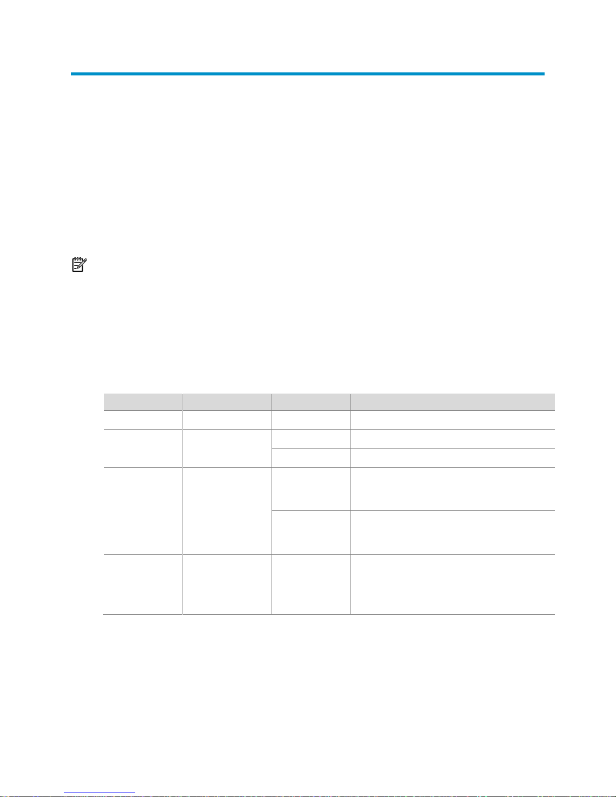
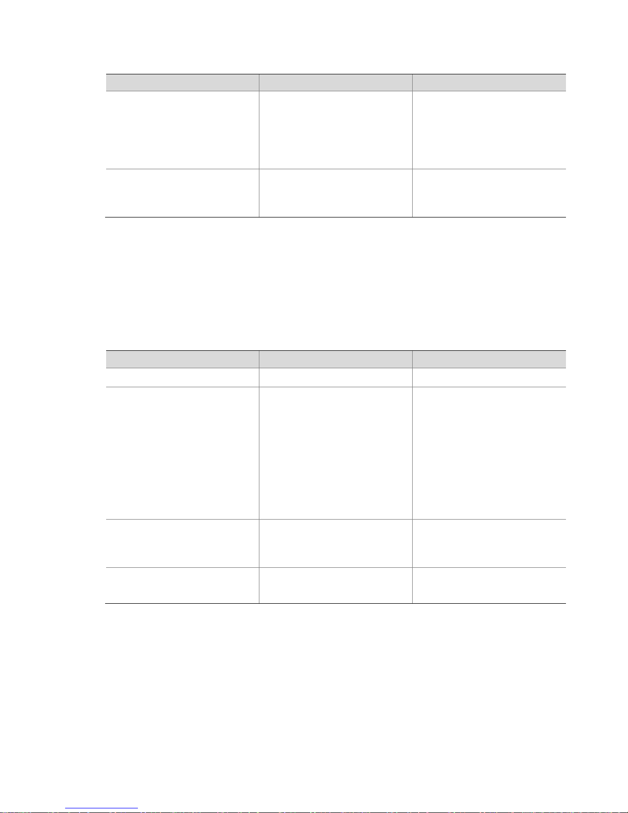
ACL classification
ACLs fall into four categories, as shown in Table 1 .
Table 1 ACL categories
ACL numbering and naming
Each ACL category has a unique range of ACL numbers. When creating an ACL, you
must assign it a number for identification, and in addition, you can also assign the ACL a
8
Page 9
name for the ease of identification. After creating an ACL with a name, you can neither
ACL category
Depth-first rule sorting procedures
IPv4 basic ACL
1. The rule configured with a VPN instance takes precedence.
2. The rule with more 0s in the source IP address wildcard mask takes
precedence. More 0s means a narrower IP address range.
3. The rule with a smaller rule ID takes precedence.
rename it nor delete its name.
You cannot assign a name for a WLAN ACL.
For a WLAN ACL, the ACL number and name must be globally unique. For an IPv4 basic
or advanced ACLs, its ACL number and name must be unique among all IPv4 ACLs, and
for an IPv6 basic or advanced ACL, among all IPv6 ACLs. You can assign an IPv4 ACL
the same number and name as an IPv6 ACL.
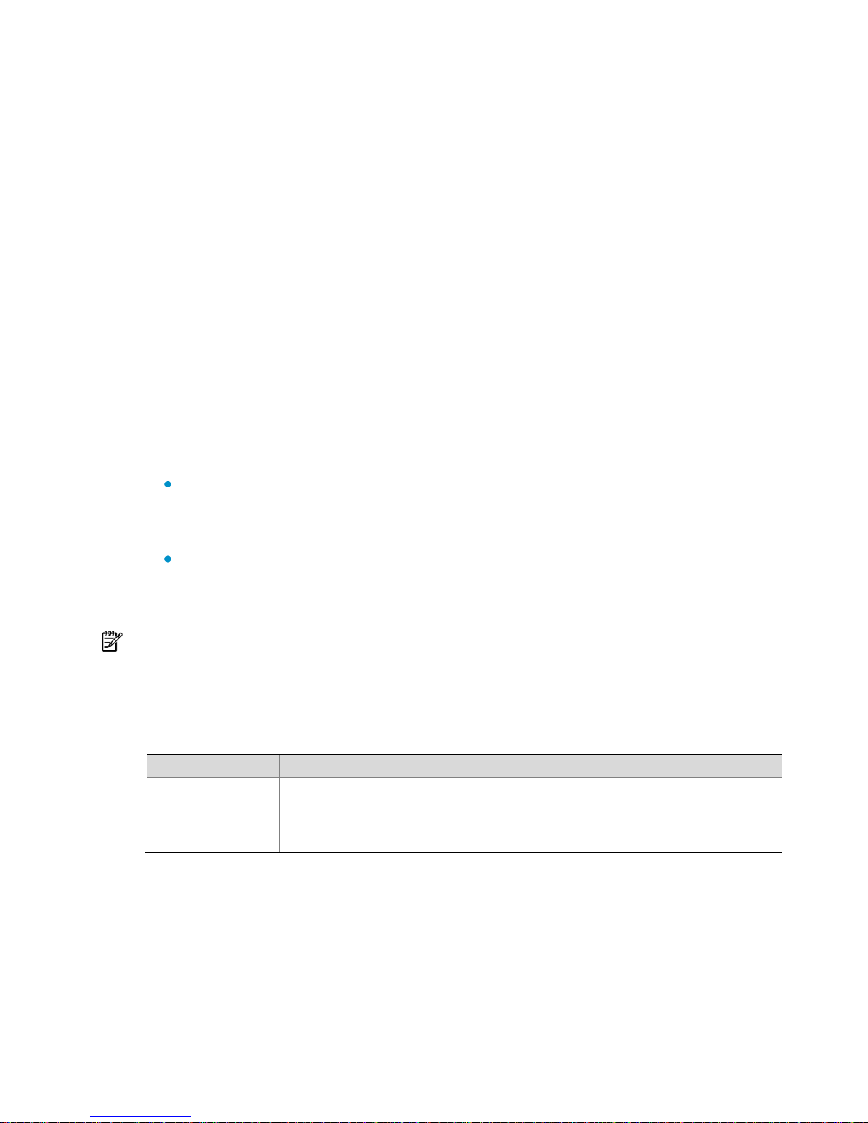
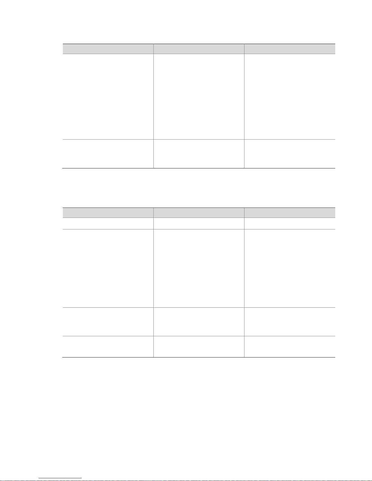
Match order
The rules in an ACL are sorted in certain order. When a packet matches a rule, the
device stops the match process and performs the action defined in the rule. If an ACL
contains overlapping or conflicting rules, the matching result and action to take
depend on the rule order.
Two ACL match orders are available:
config: Sorts ACL rules in ascending order of rule ID. A rule with a lower ID is
matched before a rule with a higher ID. If you use this approach, check rule
content and order carefully.
auto: Sorts ACL rules in depth-first order. Depth-first ordering ensures that any subset
of a rule is always matched before the rule. The depth-first ordering procedure
varies with ACL categories, as shown in Table 2 .
NOTE:
The rule order of WLAN ACLs can only be config.
Table 2 Sorting ACL rules in depth-first order
9
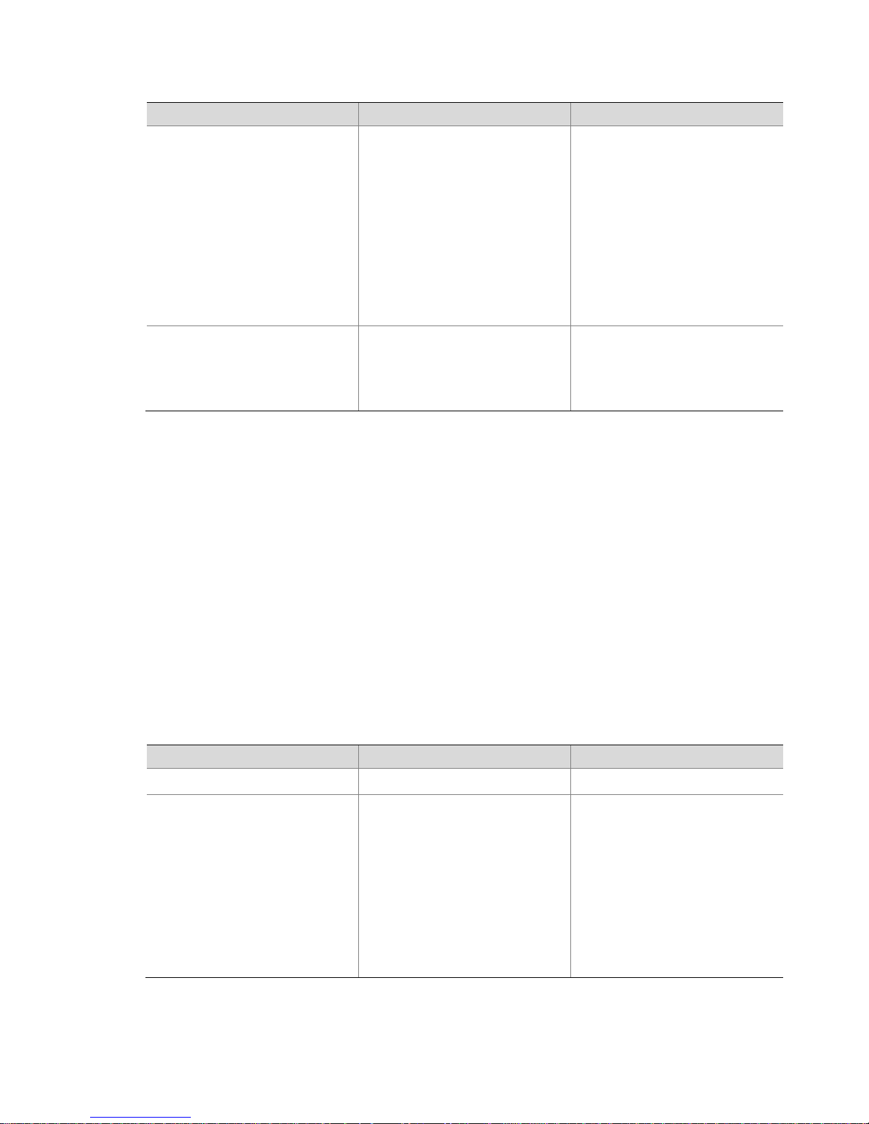
Page 10
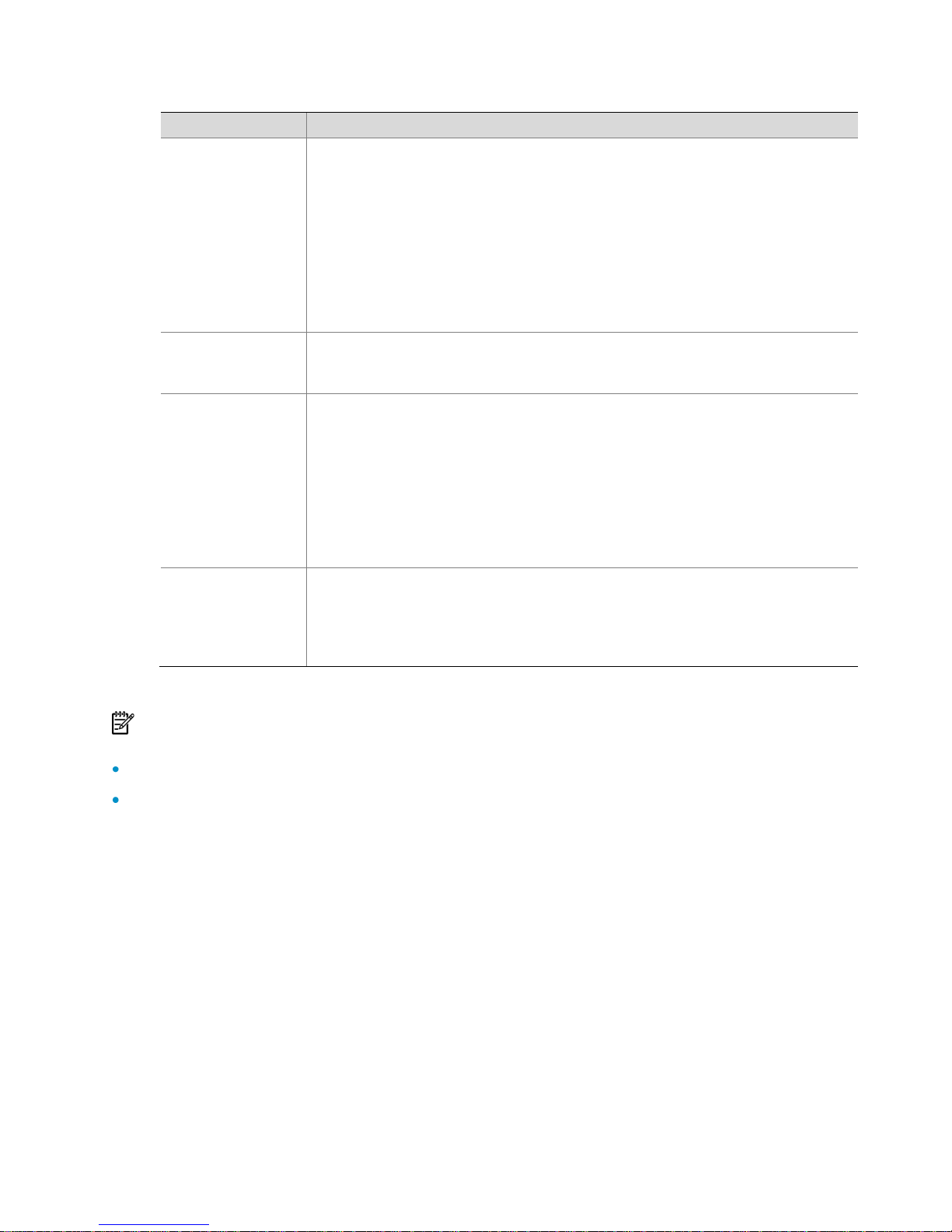
ACL category
Depth-first rule sorting procedures
IPv4 advanced
ACL
1. The rule configured with a VPN instance takes precedence.
2. The rule configured with a specific protocol is prior to a rule with the
protocol type set to IP. IP represents any protocol over IP.
3. The rule with more 0s in the source IP address wildcard mask takes
precedence. More 0s means a narrower IP address range.
4. The rule with more 0s in the destination IP address wildcard mask takes
precedence.
5. The rule with a narrower TCP/UDP service port number range takes
precedence.
6. The rule with a smaller ID takes precedence.
IPv6 basic ACL
1. The rule configured with a longer prefix for the source IP address takes
precedence. A longer prefix means a narrower IP address range.
2. The rule with a smaller ID takes precedence.
IPv6 advanced
ACL
1. The rule configured with a specific protocol is prior to a rule with the
protocol type set to IP. IP represents any protocol over IPv6.
2. The rule configured with a longer prefix for the source IPv6 address has a
higher priority.
3. The rule configured with a longer prefix for the destination IPv6 address
takes precedence.
4. The rule with a narrower TCP/UDP service port number range takes
precedence.
5. The rule with a smaller ID takes precedence.
Ethernet frame
header ACL
1. The rule with more 1s in the source MAC address mask takes precedence.
More 1s means a smaller MAC address.
2. The rule with more 1s in the destination MAC address mask takes
precedence.
3. The rule with a smaller ID takes precedence.
NOTE:
Currently, the AC does not support ACL rules with the VPN instance attribute.
A wildcard mask, also called an inverse mask, is a 32-bit binary and represented in dotted
decimal notation. In contrast to a network mask, the 0 bits in a wildcard mask represent ‗do
care‘ bits, while the 1 bits represent 'don‘t care bits.' If the 'do care' bits in an IP address are
identical to the 'do care' bits in an IP address criterion, the IP address matches the criterion. All
'don‘t care' bits are ignored. The 0s and 1s in a wildcard mask can be noncontiguous. For
example, 0.255.0.255 is a valid wildcard mask.
10
Page 11

ACL rule numbering
ACL rule numbering step
If you do not assign an ID for the rule you are creating, the system automatically assigns
it a rule ID. The rule numbering step sets the increment by which the system
automatically numbers rules. For example, the default ACL rule numbering step is 5. If
you do not assign IDs to rules you are creating, they are numbered 0, 5, 10, 15, and so on.
The wider the numbering step, the more rules you can insert between two rules.
By introducing a gap between rules rather than contiguously numbering rules, you have
the flexibility of inserting rules in an ACL. This feature is important for a config order ACL,
where ACL rules are matched in ascending order of rule ID.
Automatic rule numbering and re-numbering
The ID automatically assigned to an ACL rule takes the nearest higher multiple of the
numbering step to the current highest rule ID, starting with 0.
For example, if the numbering step is 5 (the default), and there are five ACL rules
numbered 0, 5, 9, 10, and 12, the newly defined rule is numbered 15. If the ACL does not
contain any rule, the first rule is numbered 0.
Whenever the step changes, the rules are renumbered, starting from 0. For example, if
there are five rules numbered 5, 10, 13, 15, and 20, changing the step from 5 to 2 causes
the rules to be renumbered 0, 2, 4, 6 and 8.
Implementing time-based ACL rules
You can implement ACL rules based on the time of day by applying a time range to
them. A time-based ACL rule takes effect only in any time periods specified by the time
range.
Two basic types of time range are available:
Periodic time range, which recurs periodically on a day or days of the week.
Absolute time range, which represents only a period of time and does not recur.
You may apply a time range to ACL rules before or after you create it. However, the
rules using the time range can take effect only after you define the time range.
11
Page 12

IPv4 fragments filtering with ACLs
Traditional packet filtering matched only first fragments of IPv4 packets, and allowed all
subsequent non-first fragments to pass through. This mechanism resulted in security risks,
because attackers may fabricate non-first fragments to attack networks.
To avoids the risks, the H3C ACL implementation:
Filters all fragments by default, including non-first fragments.
Provides standard and exact match modes for matching ACLs that contain
advanced attributes such as TCP/UDP port number and ICMP type. Standard
match is the default mode. It considers only Layer 3 attributes. Exact match
considers all header attributes defined in IPv4 ACL rules.
ACL configuration task list
IPv4 ACL configuration task list
Complete the following tasks to configure an IPv4 ACL:
Creating a time range (Optional)
The following four tasks are required: (Configure at least one task.)
Configuring a WLAN ACL
Configuring an IPv4 basic ACL
Configuring an IPv4 advanced ACL
Configuring an Ethernet frame header ACL
Copying an IPv4 ACL (Optional)
IPv6 ACL configuration task list
Complete the following tasks to configure an IPv6 ACL:
Creating a time range (Optional)
The following two tasks are required: (Configure at least one task.)
Configuring an IPv6 basic ACL
Configuring an IPv6 advanced ACL
Copying an IPv6 ACL (Optional)
12
Page 13
To do…
Use the command…
Remarks
Enter system view
system-view
––
Create a time range
time-range
time-range-name
{ start-time to end-time days
[ from time1 date1 ] [ to
time2 date2 ] | from time1
date1 [ to time2 date2 ] | to
time2 date2 }
Required
By default, no time range
exists.
To do…
Use the command…
Remarks
Enter system view
system-view
––
Create a WLAN ACL and
enter its view
acl number acl-number
Required
By default, no ACL exists.
WLAN ACLs are numbered in
the range 100 to 199.
Configure a description for
the WLAN ACL
description text
Optional
By default, a WLAN ACL has
no ACL description.
Set the rule numbering step
step step-value
Optional
5 by default
Configuring an ACL
Creating a time range
Follow these steps to create a time range:
You may create time ranges identified with the same name. They are regarded as one
time range whose active period is the result of ORing periodic ones, ORing absolute
ones, and ANDing periodic and absolute ones.
You may create a maximum of 256 uniquely named time ranges, each with 32 periodic
time ranges at most and 12 absolute time ranges at most.
Configuring a WLAN ACL
WLAN ACLs match packets based on SSIDs of wireless clients.
Follow these steps to configure a WLAN ACL:
13
Page 14
To do…
Use the command…
Remarks
Create or edit a rule
rule [ rule-id ] { permit |
deny } [ ssid ssid-name ]
Required
By default, a WLAN ACL
does not contain any rule.
To create or edit multiple
rules, repeat this step.
Configure or edit a rule
description
rule rule-id comment text
Optional
By default, a WLAN ACL rule
has no description.
To do…
Use the command…
Remarks
Enter system view
system-view
––
Create an IPv4 basic ACL
and enter its view
acl number acl-number
[ name acl-name ]
[ match-order { auto |
config } ]
Required
By default, no ACL exists.
IPv4 basic ACLs are
numbered in the range 2000
to 2999.
You can use the acl name
acl-name command to
enter the view of an existing
named IPv4 ACL.
Configure a description for
the IPv4 basic ACL
description text
Optional
By default, an IPv4 basic
ACL has no ACL description.
Set the rule numbering step
step step-value
Optional
5 by default
Configuring a basic ACL
Configuring an IPv4 basic ACL
IPv4 basic ACLs match packets based on only source IP address.
Follow these steps to configure an IPv4 basic ACL:
14
Page 15
To do…
Use the command…
Remarks
Create or edit a rule
rule [ rule-id ] { deny |
permit } [ fragment | logging
| source { sour-addr
sour-wildcard | any } |
time-range
time-range-name ] *
Required
By default, an IPv4 basic
ACL does not contain any
rule.
To create or edit multiple
rules, repeat this step.
The logging keyword takes
effect only when the
module that uses the ACL
supports logging.
Configure or edit a rule
description
rule rule-id comment text
Optional
By default, an IPv4 ACL rule
has no rule description.
To do…
Use the command…
Remarks
Enter system view
system-view
––
Create an IPv6 basic ACL
view and enter its view
acl ipv6 number
acl6-number [ name
acl6-name ] [ match-order
{ auto | config } ]
Required
By default, no ACL exists.
IPv6 basic ACLs are
numbered in the range 2000
to 2999.
You can use the acl ipv6
name acl6-name command
to enter the view of an
existing named IPv6 ACL.
Configure a description for
the IPv6 basic ACL
description text
Optional
By default, an IPv6 basic
ACL has no ACL description.
Set the rule numbering step
step step-value
Optional
5 by default
Configuring an IPv6 basic ACL
Follow these steps to configure an IPv6 basic ACL:
15
Page 16
To do…
Use the command…
Remarks
Create or edit a rule
rule [ rule-id ] { deny |
permit } [ fragment | logging
| source { ipv6-address
prefix-length |
ipv6-address/prefix-length |
any } | time-range
time-range-name ] *
Required
By default, an IPv6 basic
ACL does not contain any
rule.
To create or edit multiple
rules, repeat this step.
The logging keyword takes
effect only when the
module using the ACL
supports logging.
Configure or edit a rule
description
rule rule-id comment text
Optional
By default, an IPv6 basic
ACL rule has no rule
description.
To do…
Use the command…
Remarks
Enter system view
system-view
––
Create an IPv4 advanced
ACL and enter its view
acl number acl-number
[ name acl-name ]
[ match-order { auto |
config } ]
Required
By default, no ACL exists.
IPv4 advanced ACLs are
numbered in the range 3000
to 3999.
You can use the acl name
acl-name command to
enter the view of an existing
named IPv4 ACL.
Configuring an advanced ACL
Configuring an IPv4 advanced ACL
IPv4 advanced ACLs match packets based on source and destination IP addresses,
protocols over IP, and other protocol header information, such as TCP/UDP source and
destination port numbers, TCP flags, ICMP message types, and ICMP message codes.
IPv4 advanced ACLs also allow you to filter packets based on three priority criteria: type
of service (ToS), IP precedence, and differentiated services codepoint (DSCP) priority.
Compared with IPv4 basic ACLs, IPv4 advanced ACLs allow of more flexible and
accurate filtering.
Follow these steps to configure an IPv4 advanced ACL:
16
Page 17

To do…
Use the command…
Remarks
Configure a description for
the IPv4 advanced ACL
description text
Optional
By default, an IPv4
advanced ACL has no ACL
description.
Set the rule numbering step
step step-value
Optional
5 by default
Create or edit a rule
rule [ rule-id ] { deny |
permit } protocol [ { { ack
ack-value | fin fin-value |
psh psh-value | rst rst-value
| syn syn-value | urg
urg-value } * | established }
| destination { dest-addr
dest-wildcard | any } |
destination-port operator
port1 [ port2 ] | dscp dscp |
fragment | icmp-type
{ icmp-type icmp-code |
icmp-message } | logging |
precedence precedence |
reflective | source
{ sour-addr sour-wildcard |
any } | source-port operator
port1 [ port2 ] | time-range
time-range-name | tos tos] *
Required
By default, an IPv4
advanced ACL does not
contain any rule.
To create or edit multiple
rules, repeat this step.
The logging keyword takes
effect only when the
module using the ACL
supports logging.
Configure or edit a rule
description
rule rule-id comment text
Optional
By default, an IPv4
advanced ACL rule has no
rule description.
To do…
Use the command…
Remarks
Enter system view
system-view
––
Configuring an IPv6 advanced ACL
IPv6 advanced ACLs match packets based on the source IPv6 address, destination IPv6
address, protocol carried over IPv6, and other protocol header fields such as the
TCP/UDP source port number, TCP/UDP destination port number, ICMP message type,
and ICMP message code.
Compared with IPv6 basic ACLs, they allow of more flexible and accurate filtering.
Follow these steps to configure an IPv6 advanced ACL:
17
Page 18

To do…
Use the command…
Remarks
Create an IPv6
advanced ACL and
enter its view
acl ipv6 number acl6-number
[ name acl6-name ]
[ match-order { auto | config } ]
Required
By default, no ACL exists.
IPv6 advanced ACLs are
numbered in the range
3000 to 3999.
You can use the acl ipv6
name acl6-name
command to enter the
view of an existing named
IPv6 ACL.
Configure a description
for the IPv6 advanced
ACL
description text
Optional
By default, an IPv6
advanced ACL has no
ACL description.
Set the rule numbering
step
step step-value
Optional
5 by default
Create or edit a rule
rule [ rule-id ] { deny | permit }
protocol [ { { ack ack-value | fin
fin-value | psh psh-value | rst
rst-value | syn syn-value | urg
urg-value } * | established } |
destination { dest dest-prefix |
dest/dest-prefix | any } |
destination-port operator port1
[ port2 ] | dscp dscp | fragment
| icmp6-type { icmp6-type
icmp6-code | icmp6-message }
| logging | source { source
source-prefix |
source/source-prefix | any } |
source-port operator port1
[ port2 ] | time-range
time-range-name ] *
Required
By default IPv6 advanced
ACL does not contain any
rule.
To create or edit multiple
rules, repeat this step.
The logging keyword takes
effect only when the
module using the ACL
supports logging.
Configure or edit a rule
description
rule rule-id comment text
Optional
By default, an IPv6
advanced ACL rule has no
rule description.
Configuring an Ethernet frame header ACL
Ethernet frame header ACLs, also called Layer 2 ACLs, match packets based on Layer 2
protocol header fields such as source MAC address, destination MAC address, 802.1p
priority (VLAN priority), and link layer protocol type.
18
Page 19

Follow these steps to configure an Ethernet frame header ACL:
To do…
Use the command…
Remarks
Enter system view
system-view
––
Create an Ethernet frame
header ACL and enter its
view
acl number acl-number
[ name acl-name ]
[ match-order { auto |
config } ]
Required
By default, no ACL exists.
Ethernet frame header ACLs
are numbered in the range
4000 to 4999.
You can use the acl name
acl-name command to
enter the view of an existing
named Ethernet frame
header ACL.
Configure a description for
the Ethernet frame header
ACL
description text
Optional
By default, an Ethernet
frame header ACL has no
ACL description.
Set the rule numbering step
step step-value
Optional
5 by default
Create or edit a rule
rule [ rule-id ] { deny |
permit } [ cos vlan-pri |
dest-mac dest-addr
dest-mask | { lsap lsap-type
lsap-type-mask | type
protocol-type
protocol-type-mask } |
source-mac sour-addr
source-mask | time-range
time-range-name ] *
Required
By default, an Ethernet
frame header ACL does not
contain any rule.
To create or edit multiple
rules, repeat this step.
Configure or edit a rule
description
rule rule-id comment text
Optional
By default, an Ethernet
frame header ACL rule has
no rule description.
Copying an ACL
You can create an ACL by copying an existing ACL. The new ACL has the same
properties and content as the source ACL except the ACL number and name.
To copy an IPv4 or IPv6 ACL successfully, ensure that:
The destination ACL number is from the same category as the source ACL number.
19
Page 20
The source IPv4 or IPv6 ACL already exists but the destination IPv4 or IPv6 ACL does
To do…
Use the command…
Remarks
Enter system view
system-view
—
Copy an existing IPv4 ACL to
create a new IPv4 ACL
acl copy
{ source-acl-number | name
source-acl-name } to
{ dest-acl-number | name
dest-acl-name }
Required
The name keyword is not
available for WLAN ACLs
To do…
Use the command…
Remarks
Enter system view
system-view
—
Copy an existing IPv6 ACL to
generate a new one of the
same category
acl ipv6 copy
{ source-acl6-number |
name source-acl6-name } to
{ dest-acl6-number | name
dest-acl6-name }
Required
To do...
Use the command…
Remarks
Display configuration and
match statistics for one or all
IPv4 ACLs
display acl { acl-number | all | name
acl-name }
Available in any
view
Display configuration and
match statistics for one or all
IPv6 ACLs
display acl ipv6 { acl6-number | all |
name acl6-name }
Available in any
view
Display the configuration
and status of one or all time
ranges
display time-range
{ time-range-name | all }
Available in any
view
Clear statistics on one or all
IPv4 ACLs
reset acl counter { acl-number | all |
name acl-name }
Available in user
view
Clear statistics on one or all
IPv6 basic and advanced
ACLs
reset acl ipv6 counter { acl6-number |
all | name acl6-name }
Available in user
view
not.
Copying an IPv4 ACL
Follow these steps to copy an IPv4 ACL:
Copying an IPv6 ACL
Follow these steps to copy an IPv6 ACL:
Displaying and maintaining ACLs
20
Page 21
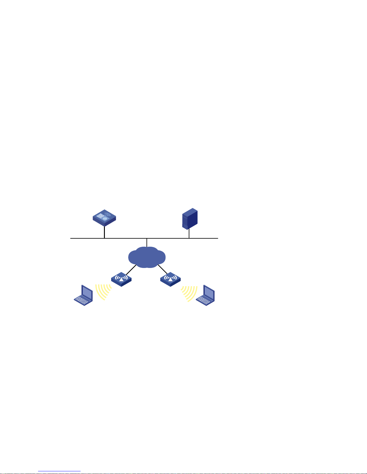
AC
GE 1/0/1
Server
192.168.1.2
IP network
AP 1 AP 2
Client A Client B
ACL configuration examples
IPv4 ACL configuration example
Network Requirements
As shown in Figure 1 , a company interconnects its wireless users and servers through the
access controller (AC). The salary server uses IP address 192.168.1.2. The wireless users in
the research and development (R&D) department are connected to the wireless
interface WLAN-ESS 1 of the AC.
Configure an ACL to deny access from the wireless users in R&D department to the
salary server during office hours (from 8:00 to 18:00) on working days.
Figure 1 Network diagram for ACL configuration
Configuration procedure
1. Create a time range for office hours:
Create a periodic time range from 8:00 to 18:00 on working days:
<AC> system-view
[AC] time-range trname 8:00 to 18:00 working-day
2. Define an ACL to control access to the salary server:
a. Create an advanced IPv4 ACL numbered 3000 and enter its view:
[AC] acl number 3000
21
Page 22

b. Create a rule to match packets from the R&D department to the salary server in
the time range:
[AC-acl-adv-3000] rule 0 permit ip source any destination 192.168.1.2
0.0.0.0 time-range trname
[AC-acl-adv-3000] quit
3. Apply the ACL
Apply IPv4 ACL 3000 to filter incoming packets on interface WLAN-ESS 1.
[AC] traffic classifier test
[AC-classifier-test] if-match acl 3000
[AC-classifier-test] quit
[AC] traffic behavior test
[AC-behavior-test] filter deny
[AC-behavior-test] quit
[AC] qos policy test
[AC-qospolicy-test] classifier test behavior test
[AC-qospolicy-test] quit
[AC] interface WLAN-ESS 1
[AC-WLAN-ESS1] qos apply policy test inbound
IPv6 ACL configuration example
Network requirements
Perform IPv6 packet filtering in the inbound direction of interface WLAN-ESS 1 to deny all
IPv6 packets but those with source addresses in the range 4050::9000 to 4050::90FF.
Configuration procedure
1. Create an IPv6 ACL:
<Sysname> system-view
[Sysname] acl ipv6 number 2000
[Sysname-acl6-basic-2000] rule deny source 4050::9000 120
[Sysname-acl6-basic-2000] rule permit source any
[Sysname-acl6-basic-2000] quit
2. Configure a traffic classifier:
[Sysname] traffic classifier ipv6-2000
[Sysname-classifier-ipv6-2000] if-match acl ipv6 2000
[Sysname-classifier-ipv6-2000] quit
3. Configure a traffic behavior:
[Sysname] traffic behavior deny
[Sysname-behavior-deny] filter deny
[Sysname] quit
4. Configure a QoS policy:
22
Page 23

[Sysname] qos policy deny2000
[Sysname-qospolicy-deny2000] classifier ipv6-2000 behavior deny
[Sysname-qospolicy-deny2000] quit
5. Apply the policy to filter incoming packets on interface WLAN-ESS 1:
[Sysname] interface WLAN-ESS1
[Sysname-WLAN-ESS1] qos apply policy deny2000 inbound
23
Page 24

2 QoS overview
In data communications, Quality of Service (QoS) is the ability of a network to provide
differentiated service guarantees for diversified traffic regarding bandwidth, delay, jitter,
and drop rate.
Network resources are always scarce. The contention for resources demands that QoS
prioritize important traffic flows over trivial traffic flows. When making a QoS scheme, a
network administrator must consider the characteristics of various applications to
balance the interests of diversified users and fully utilize network resources.
The subsequent section describes some typical QoS service models and widely used
mature QoS techniques.
NOTE:
The interfaces on your access controller may appear different in type and number from the GE
interfaces used in the examples in this manual.
To ensure that the precedence mapping function can operate properly, use the undo l2fw
fast-forwarding command to disable Layer-2 fast forwarding. For more information about
Layer 2 fast forwarding, see Layer-2 Forwarding in the Layer 2 – LAN Switching Configuration
Guide.
QoS service models
The three typical QoS service models are:
Best-effort service model
IntServ model
DiffServ model
Best-effort service model
Best effort is a single service model and also the simplest service model. In the best effort
service model, the network does its best to deliver packets but does not guarantee
delay or reliability.
The best-effort service model is the default model in the Internet and applies to most
network applications. It uses the first in first out (FIFO) queuing mechanism.
24
Page 25

IntServ model
The integrated service (IntServ) model is a multiple-service model that can
accommodate diverse QoS requirements. It provides the most granularly differentiated
QoS by identifying and guaranteeing definite QoS for each data flow.
In the IntServ model, an application must request service from the network before it
sends data. IntServ signals the service request with the Resource Reservation Protocol
(RSVP). All nodes that receive the request reserve resources as requested and maintain
state information for the application flow.
The IntServ model demands high storage and processing capabilities, because it
requires that all nodes along the transmission path maintain resource state information
for each flow. The model is suitable for small-sized or edge networks, but not large-sized
networks, for example, the core layer of the Internet, where billions of flows are present.
DiffServ model
The differentiated service (DiffServ) model is a multiple-service model that can satisfy
diverse QoS requirements. It is easy to implement and extend. Unlike IntServ, DiffServ
does not require an application to signal the network to reserve resources before
sending data.
All QoS techniques in this document are based on the DiffServ model.
QoS techniques
The QoS techniques fall into traffic classification, traffic policing, traffic shaping, line rate,
congestion management, and congestion avoidance. The following section briefly
introduces these QoS techniques.
25
Page 26

Applying QoS techniques in a network
WAN
Traffic classification
Traffic policing
Congestion management
Congestion avoidance
Traffic shaping
Traffic policing
Traffic policing
Traffic direction
Congestion management
Congestion avoidance
Traffic shaping
Traffic policing
Figure 2 Positions of the QoS techniques in a network
As shown in Figure 2 , traffic classification, traffic shaping, traffic policing, congestion
management, and congestion avoidance mainly implement the following functions:
Traffic classification uses certain match criteria to assign packets with the same
characteristics to a class. Based on classes, differentiated services can be
provided.
Traffic policing polices flows entering or leaving an AC and can be applied to the
incoming traffic and outgoing traffic of a port. When a flow exceeds the pre-set
threshold, some restriction or punishment measures can be taken to prevent
overconsumption of network resources.
Traffic shaping proactively adapts the output rate of traffic to the network
resources available on the downstream AC to eliminate packet drop and delay.
Traffic shaping is usually applied to the outgoing traffic of a port.
Congestion management provides a resource scheduling policy to arrange the
forwarding sequence of packets when congestion occurs. Congestion
management is usually applied to the outgoing traffic of a port.
Congestion avoidance monitors the usage status of network resources and is
usually applied to the outgoing traffic of a port. As congestion becomes worse, it
actively reduces the queue length by dropping packets.
26
Page 27

QoS processing flow in an AC
Traffic policing
Priority marking
Classify the
traffic
Classification
Packets received
on the interface
Tokens
Drop
Other
proce
ssing
Token bucket
CAR Remark
Toekn
Classify the
traffic
Classification
Packets to be
sent out the
interface
Drop
Other
proces
sing
Drop
Queuing
Enqueue
Queue 0
Queue 1
Queue 2
Queue N
...
Dequeue
Transmit
Queues
Token bucket
Traffic policing
Traffic shaping
Congestion
avoidance
CAR
GTS
WRED
Congestion
management
Figure 3 QoS processing flow
Figure 3 shows how the QoS module processes traffic:
Traffic classifier identifies and classifies traffic for subsequent QoS actions.
The QoS module takes various QoS actions on classified traffic as configured,
depending on the traffic processing phase and network status. For example, you
may configure the QoS module to perform traffic policing for incoming traffic,
traffic shaping for outgoing traffic, congestion avoidance before congestion
occurs, and congestion management when congestion occurs.
27
Page 28

3 QoS configuration approaches
Two approaches are available for configuring QoS:
Non-policy approach
Policy approach
Some features support both approaches, but some support only one.
Non-policy approach
In non-policy approach, you configure QoS service parameters directly without using a
QoS policy. For example, you can use the line rate feature to set a rate limit on an
interface without using a QoS policy.
Policy approach
In policy approach, you configure QoS service parameters by using QoS policies. A QoS
policy defines the shaping, policing, or other QoS actions to take on different classes of
traffic. It is a set of class-behavior associations.
A class is a set of match criteria for identifying traffic. It uses the AND or OR operator:
If the operator is AND, a packet must match all the criteria to match the class.
If the operator is OR, a packet matches the class if it matches any of the criteria in
the class.
A traffic behavior defines a set of QoS actions to take on packets, such as priority
marking and redirect.
By associating a traffic behavior with a class in a QoS policy, you apply the specific set
of QoS actions to the class of traffic.
Configuring a QoS policy
Figure 4 shows how to configure a QoS policy.
28
Page 29

Define a class
Define a behavior
Define a policy
Apply the policy
Apply the
policy to an
interface or
PVC
Apply the
policy to
online
users
To do…
Use the command…
Remarks
Enter system view
system-view
—
Create a class and enter
class view
traffic classifier tcl-name
[ operator { and | or } ]
Required
By default, the operator of a
class is AND.
The operator of a class can
be AND or OR.
AND: A packet is assigned
to a class only when the
packet matches all the
criteria in the class.
OR: A packet is assigned to
a class if it matches any of
the criteria in the class.
Figure 4 QoS policy configuration procedure
Defining a class
To define a class, specify its name and then configure the match criteria in class view.
Follow these steps to define a class:
29
Page 30

To do…
Use the command…
Remarks
Configure match criteria
if-match match-criteria
Required
For more information, see
the if-match command in
QoS in the ACL and QoS
Command Reference.
Display information about a
specific or all classes
display traffic classifier
user-defined [ tcl-name ]
Optional
Available in any view
To do…
Use the command…
Remarks
Enter system view
system-view
—
Create a traffic
behavior and enter
traffic behavior
view
traffic behavior
behavior-name
Required
Configure traffic
accounting
accounting
Optional
Traffic is counted in bytes.
Configure a CAR
action
car cir
committed-information-rate
[ cbs committed-burst-size
[ ebs excess-burst-size ] ] [ pir
peak-information-rate ]
[ green action ] [ red action ]
Optional
For more information about traffic
policing, see Traffic policing and
line rate configuration.
Support for the parameters of the
command varies by AC model. For
more information, see QoS in the
ACL and QoS Command
Reference.
Drop or send
packets
filter { deny | permit }
Optional
deny means dropping packets,
and permit means permitting
packets to pass through.
Set the 802.1p
precedence
remark dot1p 8021p
Optional
Defining a traffic behavior
A traffic behavior is a set of QoS actions (such as traffic filtering, traffic policing, and
priority marking) to take on a class of traffic. To define a traffic behavior, first create it
and then configure QoS actions (such as priority marking and traffic policing) in traffic
behavior view.
Follow these steps to define a traffic behavior:
30
Page 31

To do…
Use the command…
Remarks
Set the local
precedence for
packets
remark local-precedence
local-precedence
Optional
Display traffic
behavior
configuration
display traffic behavior
user-defined
[ behavior-name ]
Optional
Available in any view
To do…
Use the command…
Remarks
Enter system view
system-view
—
Create a policy and enter
policy view
qos policy policy-name
Required
Associate a class with a
behavior in the policy
classifier tcl-name behavior
behavior-name
Required
Repeat this step to create
more class-behavior
associations.
Display information about a
class and its associated
behavior in a specific policy
display qos policy
user-defined [ policy-name
[ classifier tcl-name ] ]
Optional
Available in any view
Defining a policy
In a policy, you can define multiple class-behavior associations. Class-behavior
associations are matched in the order they are configured. A behavior is performed for
the associated class of packets. In this way, various QoS features are implemented.
Follow these steps to associate a class with a behavior in a policy:
NOTE:
If an ACL is referenced in a QoS policy for traffic classification, the packet matching procedure
differs with AC models:
On the WX5002, if a deny rule in the ACL is matched, the if-match clause is ignored and the
matching process continues.
On any other WX series ACs, the ACL is used for classification only and thus the permit/deny
action in ACL rules is ignored. Actions taken on matching packets are defined in traffic
behaviors.
31
Page 32

To do…
Use the command…
Remarks
Enter system view
system-view
—
Enter
interface
view or
port group
view
Enter
interface
view
interface interface-type
interface-number
Use either command
Settings in interface view
take effect on the current
interface. Settings in port
group view take effect on all
ports in the port group.
Enter port
group
view
port-group manual
port-group-name
Apply the policy to the
interface/port group
qos apply policy policy-name
{ inbound | outbound }
Required
Display information
about the QoS policies
applied to an interface
display qos policy interface
[ interface-type
interface-number ] [ inbound |
outbound ]
Optional
Available in any view
Display information
about a specific class
and its associated
behavior in a specific
policy
display qos policy user-defined
[ policy-name [ classifier
tcl-name ] ]
Optional
Available in any view
Applying the QoS policy
You can apply a QoS policy to different occasions:
Applied to an interface, the policy takes effect on the traffic sent or received on
the interface.
Applied to a user profile, the policy takes effect on the traffic sent or received by
the online users of the user profile.
Applying the QoS policy to an interface
A policy can be applied to multiple interfaces, but only one policy can be applied in
one direction (inbound or outbound) of an interface.
Follow these steps to apply the QoS policy to an interface:
NOTE:
The QoS policy applied to the outgoing traffic of an interface does not regulate local packets.
Local packets are critical protocol packets sent by the local system for maintaining the operation
of the AC. To avoid drop of these packets, QoS does not process them. Commonly used local
packets include link maintenance packets, IS-IS packets, OSPF packets, RIP packets, BGP
packets, LDP packets, RSVP packets, and SSH packets.
32
Page 33

To do…
Use the command…
Remarks
Enter system view
system-view
—
Enter user profile view
user-profile profile-name
Required
The configuration made in
user profile view takes
effect when the user-profile
is activated and there are
online users.
For more information about
user profiles, see User Profile
in the Security
Configuration Guide.
Apply the QoS policy
qos apply policy policy-name
{ inbound | outbound }
Required
Use the inbound keyword to
apply the QoS policy to the
traffic received by the
online users. Use the
outbound keyword to apply
the QoS policy to the traffic
sent by the online users.
Return to system view
quit
—
Activate the user profile
user-profile profile-name
enable
Required
Inactive by default
Applying the QoS policy to online users
You can apply a QoS policy to traffic of multiple online users, but only one policy can be
applied in one traffic direction. To modify a QoS policy already applied in a certain
direction, remove the QoS policy application first.
Follow these steps to apply the QoS policy to online users:
NOTE:
If a user profile is active, the QoS policy applied to it cannot be configured or removed,
except ACLs referenced in the QoS policy. However, when the users of the user profile are
online, the referenced ACLs cannot be modified either.
The QoS policies applied in user profile view support only the remark, car, and filter actions.
Do not apply a null policy in user profile view, because you cannot activate a user profile with
a null policy applied.
33
Page 34

To do…
Use the command…
Remarks
Display user-defined QoS
policy configuration
display qos policy user-defined
[ policy-name [ classifier tcl-name ] ]
Available in any
view
Display QoS policy
configuration on the
specified or all interfaces
display qos policy interface
[ interface-type interface-number ]
[ inbound | outbound ]
Available in any
view
Display traffic class
configuration
display traffic classifier user-defined
[ tcl-name ]
Available in any
view
Display traffic behavior
configuration
display traffic behavior user-defined
[ behavior-name ]
Available in any
view
Displaying and maintaining QoS policies
34
Page 35

4 Priority mapping configuration
Priority mapping overview
When a packet arrives, an AC assigns a set of QoS priority parameters to the packet
based on a certain priority field carried in the packet or the port priority of the incoming
port depending on your configuration. This process is called priority mapping. The set of
QoS priority parameters decides the scheduling priority and forwarding priority of the
packet.
Priority mapping is implemented with priority mapping tables and involves priorities
including 802.11e priority, 802.1p priority, DSCP, and local precedence on the H3C WX
series access controllers.
Local precedence is assigned by the AC and is of only local significance. Local
precedence is used for queuing. A local precedence value corresponds to an output
queue. A packet with higher local precedence is assigned to a higher priority output
queue to be preferentially scheduled.
Priority mapping tables
The AC provides various priority mapping tables, or rather, priority mappings. By looking
up a priority mapping table, the AC decides which priority value is to assign to a packet
for subsequent packet processing.
The default priority mapping tables are available for priority mapping. They are sufficient
in most cases. If a default priority mapping table cannot meet your requirements, you
can modify the priority mapping table as needed.
NOTE:
For the default dot11e-lp priority mapping table, an input value yields a target value that is equal
to it.
The default priority mapping tables are as follows:
35
Page 36

802.1p priority (dot1p)
Local precedence (lp)
0
2
1
0
2 1 3
3
4
4
5 5 6
6
7
7
DSCP
Local precedence (lp)
0 to 7
0
8 to 15
1
16 to 23
2
24 to 31
3
32 to 39
4
40 to 47
5
48 to 55
6
56 to 63
7
Local precedence (lp)
802.1p priority (dot1p)
0
1
1 2 2
0
3
3
4 4 5
5
6
6
7
7
Table 3 The default dot1p-lp priority mapping table
Table 4 The default dscp-lp priority mapping table
Table 5 The default lp-dot1p priority mapping table
36
Page 37

Port priority
Local precedence (lp)
0 0 1
1
2
2
3 3 4
4
5
5
6
6
7
7
Local precedence (lp)
DSCP
0 0 1 8 2
16 3 24 4 32 5 40 6 48 7 56
Table 6 The default port priority-to-local priority mapping table
Table 7 The default lp-dscp priority mapping table
Priority mapping configuration tasks
You can configure priority mapping in two approaches:
Configuring priority trust mode. In this approach, you can configure a port to look
up a certain priority, 802.1p for example, in incoming packets, in the priority
mapping tables. If an incoming packet does not carry the trusted priority field or if
the port is configured not to trust any packet priority, the port priority of the
incoming port is used.
Changing port priority. By default, all ports are assigned the port priority of zero. By
changing the port priority of a port, you change the priority of the incoming
packets on the port.
Perform these optional tasks to configure priority mapping:
37
Page 38

To do…
Use the command…
Remarks
Enter system view
system-view
—
Enter priority mapping
table view
qos map-table
{ dot11e-lp | dot1p-lp
| dscp-lp | lp-dot11e
| lp-dot1p | lp-dscp }
Required
Enter the view of the priority mapping
table to be modified.
Support of the H3C WX series access
controllers for priority mapping tables may
vary by AC model. For more information,
see Compatibility Matrices.
Configure the priority
mapping table
import
import-value-list
export export-value
Required
Newly configured mappings overwrite the
old ones.
Display the
configuration of the
priority mapping
table
display qos
map-table
[ dot11e-lp | dot1p-lp
| dscp-lp | lp-dot11e
| lp-dot1p | lp-dscp ]
Optional
Available in any view
Configuring a priority mapping table
Configuring a port to trust packet priority for priority mapping
Configuring the port priority of a port
Configuring priority mapping
Configuring a priority mapping table
The AC provides various types of priority mapping table, as listed below.
dot11e-lp: 802.11e-to-local priority mapping table.
dot1p-lp: 802.1p-to-local priority mapping table.
dscp-lp: DSCP-to-local priority mapping table, which is applicable to only IP
packets.
lp-dot11e: Local-to-802.11e priority mapping table.
lp-dot1p: Local-to-802.1p priority mapping table.
lp-dscp: Local-to-DSCP priority mapping table.
Follow these steps to configure a priority mapping table:
38
Page 39

To do…
Use the command…
Remarks
Enter system view
system-view
—
Enter
interface
view or
port group
view
Enter
interface
view
interface interface-type
interface-number
Use either command
Settings in interface view
take effect on the current
interface. Settings in port
group view take effect on all
ports in the port group.
Enter port
group
view
port-group manual
port-group-name
Configure the port to
use a type of packet
priority for priority
mapping
qos trust { dot11e | dot1p |
dscp }
Required
By default, port priority is
trusted.
Support for the keywords of
this command varies by
interface type and AC
model.
Display the trusted
packet priority type of
an interface/port group
display qos trust interface
[ interface-type
interface-number ]
Optional
Available in any view
Configuring a port to trust packet priority for priority mapping
This feature is available only on Layer 2 ports. You can configure a Layer 2 port to trust
one of the following priority fields in incoming packets:
dot11e: Uses the 802.11e priority of incoming packets for mapping.
dot1p: Uses the 802.1p priority of incoming packets for mapping.
dscp: Uses the DSCP precedence of incoming IP packets for mapping.
Follow these steps to configure a port to trust packet priority for priority mapping:
NOTE:
If a WLAN-ESS interface in service contains WLAN-DBSS interfaces, you cannot change its trusted
packet priority type. To change its trusted packet priority type, you must log off all online users to
stop the service the interface is providing.
Configuring the port priority of a port
If a port does not trust any packet priority, the AC uses the port priority to look for the set
of priority parameters for the incoming packets. The port priority is configurable in the
range of 0 to 7. By changing the port priority of ports, you can prioritize traffic received
on different ports.
39
Page 40

To do…
Use the command…
Remarks
Enter system view
system-view
—
Enter
interface
view or
port group
view
Enter
interface
view
interface interface-type
interface-number
Use either command.
Settings in interface view
(Ethernet or WLAN-ESS) take
effect on the current interface.
Settings in port group view take
effect on all ports in the port
group.
Enter port
group view
port-group manual
port-group-name
Configure the port priority
of the port
qos priority priority-value
Required
The default port priority is 0.
To do…
Use the command…
Remarks
Display priority mapping
table configuration
display qos map-table
[ dot11e-lp | dot1p-lp |
dscp-lp | lp-dot11e |
lp-dot1p | lp-dscp ]
Available in any view
Support fort the keywords of
the command varies by AC
model. For more
information, see QoS in the
ACL and QoS Command
Reference.
Follow these steps to configure the port priority of a port:
CAUTION:
If a WLAN-ESS interface in use contains WLAN-DBSS interfaces, you cannot modify its priority. To
modify the priority of the WLAN-ESS interface, you must log off all online users to stop the
service the interface is providing.
On a WLAN-ESS interface configured with the qos priority command, the assignment of DSCP
precedence varies by packet type. For the CAPWAP packets from an AP to the AC, DSCP
precedence is obtained from the default lp-dscp mapping table based on the port priority.
For the CAPWAP packets from the AC to the AP, DSCP precedence is obtained from the
current lp-dscp mapping table based on the port priority. The CAPWAP control packets are
always assigned the highest DSCP precedence, that is, 56.
Displaying and maintaining priority mapping
40
Page 41

To do…
Use the command…
Remarks
Display information about
the priority trust mode on a
port
display qos trust interface
[ interface-type
interface-number ]
Available in any view
Support fort the keywords of
the command varies by AC
model. For more
information, see QoS in the
ACL and QoS Command
Reference.
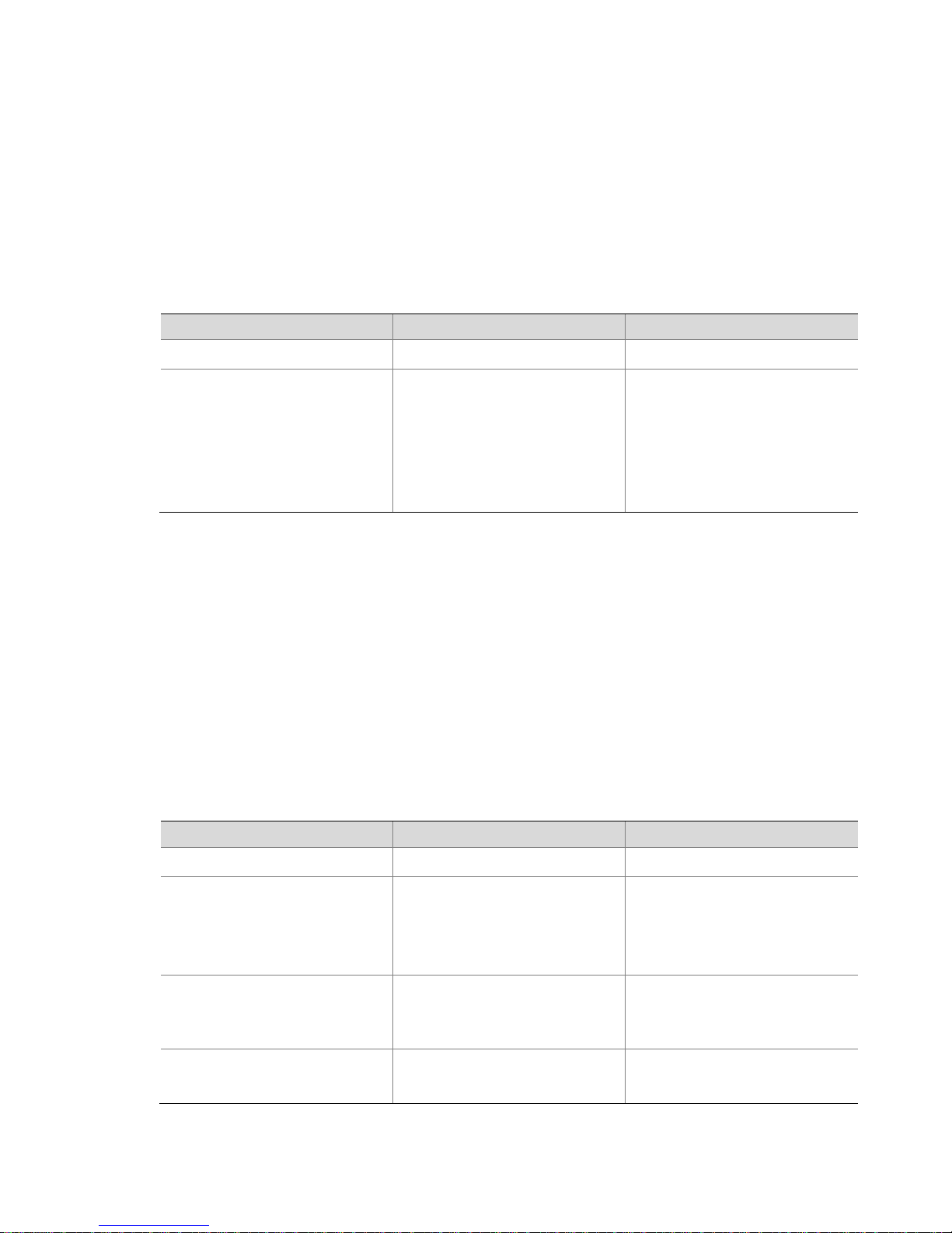
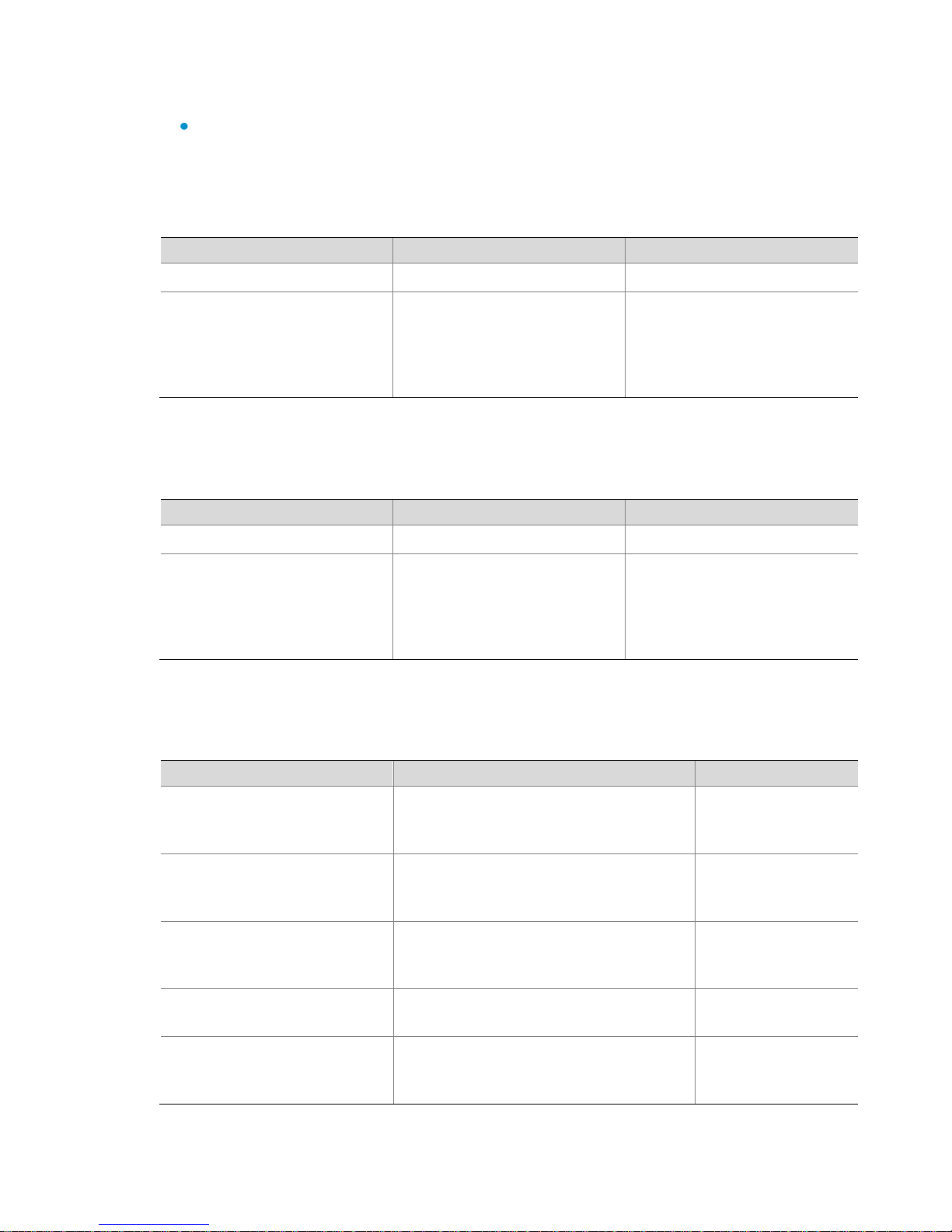
Hardware
Ethernet interface configuration prerequisites
Switches
installed
with
access
controller
modules
Access
controller
modules
LS8M1WCMA0
LSQM1WCMB0
LSBM1WCM2A0
LSRM1WCM2A1
No special requirements. You can directly
configure Ethernet interfaces on the switch.
To configure wireless features during the
configuration process, log in to the access
controller module with the oap connect slot
slot-number command.
LSWM1WCM10
LSWM1WCM20
No special requirements. You can directly
configure Ethernet interfaces on the switch.
To configure wireless features during the
configuration process, log in to the access
controller module with the mcms connect [ slot
slot-number ] system system-name command.
Unified
switches
WX3024
WX3010
WX3008
Use the oap connect slot 0 command on the
access controller engine to log in to the
switching engine.
Access
controllers
WX6103
Use the oap connect slot 0 command on the
active main control board to log in to the switch
interface board.
Priority mapping configuration examples (on WX
Series access controllers)
NOTE:
The configuration examples were created on a WX5002, which may vary by AC model.
Ethernet interface configuration may vary by AC model. For more information, see Table 8 .
Table 8 Ethernet interface configuration prerequisites
41
Page 42

Hardware
Ethernet interface configuration prerequisites
WX5002
WX5002V2
WX5004
No special requirements. You can directly
configure a GE interface on the access
controller.
AC
GE 1/0/1
IP network
AP 1
AP 3
AP 2
Trusted priority type configuration example
Network requirements
As shown in Figure 5 , the AC processes packets for AP 1, AP 2, and AP 3.
Configure the AC to enqueue packets according to their 802.1p priority and use the
user-defined priority mapping tables for priority mappings.
Figure 5 Network diagram for trusted priority type configuration
Configuration procedure
1. Enter system view:
<AC> system-view
2. Enter dot1p-lp priority mapping table view and modify the priority mapping table
parameters:
[AC] qos map-table dot1p-lp
[AC-maptbl-in-dot1p-lp] import 0 1 export 0
[AC-maptbl-in-dot1p-lp] import 2 3 export 1
[AC-maptbl-in-dot1p-lp] import 4 5 export 2
[AC-maptbl-in-dot1p-lp] import 6 7 export 3
[AC-maptbl-in-dot1p-lp] quit
3. Configure GigabitEthernet 1/0/1 to use the 802.1p priority of incoming packets for
priority mapping:
[AC] interface gigabitethernet 1/0/1
[AC-GigabitEthernet1/0/1] qos trust dot1p
42
Page 43

AC
GE 1/0/1
IP network
AP 1
AP 3
AP 2
Port priority configuration example
Network requirements
As shown in Figure 6 , the AC processes the packets of AP 1, AP 2, and AP 3. Configure
the AC to ensure that:
Incoming packets are assigned local precedence values through priority mapping
based on the port priority of receiving ports.
The default priority mapping tables of the AC are used.
The wireless interface of AP 1 is WLAN-ESS 1, that of AP 2 is WLAN-ESS 2, and that of
AP 3 is WLAN-ESS 3.
Figure 6 Network diagram for trusting port priority configuration
Configuration procedure
1. Enter system view:
<AC> system-view
2. Disable the service template bound with each WLAN-ESS interface: (Assume that
the WLAN-ESS interfaces are bound with service template 1.)
[Sysname] wlan service-template 1
[Sysname-wlan-st-1] service-template disable
[Sysname-wlan-st-1] quit
3. Set the priority of interface WLAN-ESS 1 to 1:
[AC] interface WLAN-ESS 1
[AC-WLAN-ESS1] qos priority 1
[AC-WLAN-ESS1] quit
4. Set the priority of interface WLAN-ESS 2 to 3:
[AC] interface WLAN-ESS 2
43
Page 44

[AC-WLAN-ESS2] qos priority 3
[AC-WLAN-ESS2] quit
5. Set the priority of interface WLAN-ESS 3 to 5:
[AC] interface WLAN-ESS 3
[AC-WLAN-ESS3] qos priority 5
[AC-WLAN-ESS3] quit
6. Enable service template 1:
[Sysname] wlan service-template 1
[Sysname-wlan-st-1] service-template enable
NOTE:
For more information about WLAN-ESS interfaces, see WLAN Interface in the WLAN Configuration
Guide. For information on configuring wireless services, see WLAN Service in the WLAN
Configuration Guide.
44
Page 45

5 Traffic policing and line rate
configuration
Traffic policing, traffic shaping, and rate limit are QoS techniques that help assign
network resources such as bandwidth. They increase network performance and user
satisfaction. For example, you can configure a flow to use only the resources committed
to it in a certain time range, thus avoiding network congestion caused by burst traffic.
Traffic policing and generic traffic shaping (GTS) limit traffic rate and resource usage
according to traffic specifications. Once a particular flow exceeds its specifications
such as bandwidth, it is shaped or policed to ensure that it conforms to the
specifications. Token buckets are typical tools for evaluating traffic specifications.
Traffic evaluation and token bucket
Token bucket features
A token bucket is analogous to a container that holds a certain number of tokens. Each
token represents a certain forwarding capacity, typically, a one-bit forwarding authority.
The system puts tokens into the bucket at a set rate. When the token bucket is full, the
extra tokens overflow.
Evaluating traffic with the token bucket
A token bucket mechanism evaluates traffic by looking at the number of tokens in the
bucket. To forward an n-bit packet, n tokens are required. If the number of tokens in the
bucket is enough for forwarding the packets, the traffic conforms to the specification,
and is called conforming traffic. Otherwise, the traffic does not conform to the
specification, and is called excess traffic.
A token bucket has the following configurable parameters:
Mean rate at which tokens are put into the bucket, which specifies the permitted
average rate of traffic. It is usually set to the committed information rate (CIR).
Burst size or the capacity of the token bucket. It specifies the maximum traffic size
permitted in each burst. It is usually set to the committed burst size (CBS). The set
burst size must be greater than the maximum packet size.
45
Page 46

CBS
EBS
Each arriving packet is evaluated. In each evaluation, if the number of tokens in the
bucket is enough, the traffic conforms to the specification and the tokens for forwarding
the packet are taken away; if the number of tokens in the bucket is not enough, the
traffic is excessive.
Complicated evaluation
You can set two token buckets, bucket C and bucket E, to evaluate traffic in a more
complicated environment and achieve more policing flexibility. For example, traffic
policing uses four parameters:
CIR: Rate at which tokens are put into bucket C. It specifies the average packet
transmission or forwarding rate allowed by bucket C.
CBS: Size of bucket C, which specifies the transient burst of traffic that bucket C can
forward.
Peak information rate (PIR): Rate at which tokens are put into bucket E, which
specifies the average packet transmission or forwarding rate allowed by bucket E.
Excess burst size (EBS): Size of bucket E, which specifies the transient burst of traffic
that bucket E can forward.
The two token-bucket model is as shown in Figure 7 . CBS is implemented with bucket C
and EBS with bucket E. In each evaluation, packets are measured against the buckets:
If bucket C has enough tokens, packets are colored green.
If bucket C does not have enough tokens but bucket E has enough tokens, packets
are colored yellow.
If neither bucket C nor bucket E has sufficient tokens, packets are colored red.
Figure 7 Two token-bucket model
Traffic policing
A typical application of traffic policing is to supervise the specification of certain traffic
entering a network and limit it within a reasonable range, or to "discipline" the extra
traffic. In this way, the network resources and the interests of the carrier are protected.
For example, you can limit bandwidth consumption of HTTP packets to less than 50% of
46
Page 47

Token
bucket
Packets dropped
Packet
classification
Packets to be sent
through this interface
Packets sent
Tokens are put into the
bucket at the set rate
Queue
the total. If the traffic of a certain session exceeds the limit, traffic policing can drop the
packets or reset the IP precedence of the packets. See Figure 8 .
Figure 8 Schematic diagram for traffic policing
Traffic policing is widely used in policing traffic entering the networks of internet service
providers (ISPs). It can classify the policed traffic and perform pre-defined policing
actions based on different evaluation results. These actions include:
Forwarding the packets whose evaluation result is ―conforming.‖
Dropping the packets whose evaluation result is ―excess.‖
Modifying the IP precedence of the packets whose evaluation result is
―conforming‖ and forwarding them.
Modifying the IP precedence of the packets whose evaluation result is
―conforming‖ and delivering them into the next-level traffic policing.
Entering the next-level policing (you can set multiple traffic policing levels with each
level focusing on specific objects).
Line rate
The line rate of a physical interface specifies the maximum rate for forwarding packets
(including critical packets).
Line rate also uses token buckets for traffic control. With line rate configured on an
interface, all packets to be sent through the interface are first handled by the token
bucket of line rate. If there are enough tokens in the token bucket, packets can be
47
Page 48

Packets to be forwarded
via this interface
Token
bucket
Packets sent
Put tokens into the bucket at the set rate
Queuing
Buffer queue
forwarded. Otherwise, packets are put into QoS queues for congestion management. In
this way, the traffic passing the physical interface is controlled. See Figure 9 .
Figure 9 Line rate implementation
Configuration task list
Configuring traffic policing
The token bucket mechanism limits traffic rate while accommodating bursts. It allows
bursty traffic to be transmitted as long as enough tokens are available. If tokens are
inadequate, packets cannot be transmitted until efficient tokens are generated in the
token bucket. It restricts the traffic rate to the rate for generating tokens.
Line rate limits the total rate of all packets on a physical interface. It is easier to use than
traffic policing in controlling the total traffic rate on a physical interface.
Complete the following tasks to configure traffic policing and line rate:
Configuring traffic policing
○ Configuring traffic policing in policy-based approach
○ Configuring traffic policing in non policy-based approach
Configuring line rate
You can configure traffic policing in either policy-based approach or non policy-based
approach.
48
Page 49

To do…
Use the command…
Remarks
Enter system view
system-view
—
Create a class and enter
class view
traffic classifier tcl-name [ operator { and | or } ]
—
Configure the match
criteria
if-match match-criteria
—
Exit class view
quit
—
Create a behavior and
enter behavior view
traffic behavior behavior-name
—
Configure a traffic
policing action
car cir committed-information-rate [ cbs
committed-burst-size [ ebs excess-burst-size ] ] [ pir
peak-information-rate ] [ green action ] [ red
action ]
Required
Exit behavior view
quit
—
Create a policy and
enter policy view
qos policy policy-name
—
Associate the class with
the traffic behavior in
the QoS policy
classifier tcl-name behavior behavior-name
—
Exit policy view
quit
—
Apply
the QoS
policy
To an
interface
Applying the QoS policy to an interface
—
To online
users
Applying the QoS policy to online users
—
Configuring traffic policing in policy-based approach
Follow these steps to configure traffic policing in policy-based approach:
Configuring traffic policing in non policy-based approach
NOTE:
Support of the H3C WX series access controllers for this feature may vary by AC model. For more
information, see Compatibility Matrices.
With a user profile configured, you can perform traffic policing based on users. When
any user of the user profile logs in, the authentication server automatically applies the
CAR configured for the user profile to the user. When the user logs off, the system
automatically removes the configuration without manual intervention.
49
Page 50

To do…
Use the command…
Remarks
Enter system view
system-view
—
Enter user profile view
user-profile profile-name
Required
The configuration made in user
profile view takes effect when the
user-profile is activated and the
corresponding users are online.
For more information about user
profiles, see User Profile in the
Security Configuration Guide.
Configure the CAR
action
qos car { inbound |
outbound } any cir
committed-information-rate
[ cbs committed-burst-size
[ ebs excess-burst-size ] ]
[ pir peak-information-rate ]
Required
The conforming traffic is permitted
to pass through, while the
exceeding traffic is dropped.
Support for the keywords of the
command varies by AC model. For
more information, see QoS in the
ACL and QoS Command
Reference.
Return to system view
quit
—
Activate the user
profile
user-profile profile-name
enable
Required
Inactive by default
To do…
Use the command…
Remarks
Enter system view
system-view
—
Follow these steps to configure traffic policing for all traffic of the specified online users:
NOTE:
If a user profile is activated, you cannot modify or remove the CAR policy applied to it.
Configuring line rate
NOTE:
Support of the H3C WX series access controllers for this feature may vary by AC model. For more
information, see Compatibility Matrices.
The line rate of a physical interface specifies the maximum rate of outgoing packets.
Follow these steps to configure the line rate:
50
Page 51

To do…
Use the command…
Remarks
Enter
interface
view or
port
group
view
Enter
interface
view
interface interface-type
interface-number
Use either command
Settings in interface view take
effect on the current
interface. Settings in port
group view take effect on all
ports in the port group.
Enter port
group
view
port-group manual
port-group-name
Configure the line
rate for the
interface/port group
qos lr outbound cir
committed-information-rate [ cbs
committed-burst-size [ ebs
excess-burst-size ] ]
Required
To do...
Use the command...
Remarks
Display interface line rate
configuration information
display qos lr interface
[ interface-type interface-number ]
Available in any
view
NOTE:
To enable line rate to function properly, make sure the committed-burst-size argument in the
qos lr outbound cir command is greater than or equal to 1875 or
committed-information-rate×100/16, whichever is greater. Otherwise, the physical interface
may operate improperly.
To ensure effective burst handling, set the ratio of the CBS to CIR greater than 100:16 when
configuring line rate or a traffic policing behavior.
When line rate is used in conjunction with queuing, set the queue length to 1024 to ensure that
the expected queue scheduling effect can be achieved.
Displaying and maintaining line rate
51
Page 52

100M>10M
(100M+10M+50M(>100M
100M
100M
100M
50M
10M
10M
(1( (2(
6 Congestion management
configuration
NOTE:
Support of the H3C WX series access controllers for features may vary by AC model. For more
information, see Compatibility Matrices.
Causes, impacts, and countermeasures of congestion
Congestion occurs on a link or node when traffic size exceeds the processing capability
of the link or node. It is typical of a statistical multiplexing network and can be caused by
link failures, insufficient resources, and various other causes. Figure 10 shows two
common congestion scenarios:
Figure 10 Traffic congestion causes
Congestion may bring these negative results:
Increased delay and jitter during packet transmission
Decreased network throughput and resource use efficiency
Network resource (memory in particular) exhaustion and even system breakdown
Congestion is unavoidable in switched networks or multi-user application environments.
To improve the service performance of your network, you must take measures to
manage and control it.
One major issue that congestion management deals with is how to define a resource
dispatching policy to prioritize packets for forwarding when congestion occurs.
52
Page 53

Congestion management policies
Queuing is a common technology used for congestion management. It classifies traffic
into queues and picks out packets from each queue following a certain algorithm. There
are various queuing algorithms, each addressing a particular network traffic problem.
Your choice of algorithm affects bandwidth assignment, delay, and jitter significantly.
Congestion management involves queue creating, traffic classification, packet
enqueuing, and queue scheduling. Queue scheduling treats packets with different
priorities differently to transmit high-priority packets preferentially.
This section briefly describes several common queue-scheduling mechanisms.
FIFO
Figure 11 FIFO queuing
As shown in Figure 11 , the first in first out (FIFO) uses a single queue and does not classify
traffic or schedule queues. FIFO delivers packets depending on their arrival order, with
the one arriving earlier scheduled first. The only concern of FIFO is queue length, which
affects delay and packet loss rate. On an AC, resources are assigned for packets
depending on their arrival order and load status of the AC. The best-effort service model
uses FIFO queuing.
FIFO does not address congestion problems. If there is only one FIFO output/input queue
on a port, you can hardly ensure timely delivery of mission-critical or delay-sensitive
traffic or smooth traffic jitter. The situation gets worsened if malicious traffic is present to
occupy bandwidth aggressively. To control congestion and prioritize forwarding of
critical traffic, you must use other queue scheduling mechanisms, where multiple
queues can be configured. Within each queue, however, FIFO is still used.
By default, FIFO queuing is used on interfaces.
53
Page 54

Priority queuing
Figure 12 Priority queuing (PQ)
Priority queuing is designed for mission-critical applications. The key feature of
mission-critical applications is that they require preferential service to reduce the
response delay when congestion occurs. Priority queuing can flexibly determine the
order of forwarding packets by network protocol (for example, IP), incoming interface,
packet length, source/destination address, and so on. Priority queuing classifies packets
into four queues: top, middle, normal, and bottom, in descending priority order. By
default, packets are assigned to the normal queue. Each of the four queues is a FIFO
queue.
Priority queuing schedules the four queues strictly according to the descending order of
priority, as shown in Figure 12 . It sends packets in the queue with the highest priority first.
When the queue with the highest priority is empty, it sends packets in the queue with the
second highest priority. In this way, you can assign the mission-critical packets to the
high priority queue to ensure that they are always served first. The common service
packets are assigned to the low priority queues and transmitted when the high priority
queues are empty.
The disadvantage of priority queuing is that packets in the lower priority queues cannot
be transmitted if there are packets in the higher queues for a long time.
54
Page 55

Custom queuing
Figure 13 Custom queuing (CQ)
CQ organizes packets into 16 classes (corresponding to 16 queues) by certain match
criteria. A certain class of packets enters the corresponding custom queue according to
FIFO queuing. Queues 1 through 16 are customer queues, as shown in Figure 13 . You
can define match criteria and assign a percentage of interface bandwidth for each of
these 16 customer queues. By default, packets are assigned to queue 1.
During a cycle of queue scheduling, CQ first empties the system queue. Then, it
schedules the 16 customer queues in a round robin way: it sends a certain number of
packets (based on the percentage of interface bandwidth assigned for each queue)
out of each queue in the ascending order of queue 1 to queue 16. CQ guarantees
normal packets of a certain amount of bandwidth, while ensuring that mission-critical
packets are assigned more bandwidth.
CQ can assign free bandwidth of idle queues to busy queues. Even though it performs
round robin queue scheduling, CQ does no assign fixed time slots for the queues. If a
queue is empty, CQ immediately moves to the next queue. When a class does not have
packets, the bandwidth for other classes increases.
Congestion management technology comparison
Breaking through the single congestion management policy of FIFO for traditional IP
devices, the current AC provides all the congestion management technologies above
55
Page 56

Type
Number of
queues
Advantages
Disadvantages
FIFO
1
No need to configure, easy
to use
Easy to operate, low delay
All packets are treated equally. The
available bandwidth, delay and
drop probability are determined by
the arrival order of the packets.
No restriction on the uncooperative
data sources (that is, flows without
flow control mechanism, UDP for
example), resulting in bandwidth
loss of cooperative data sources
such as TCP.
No delay guarantee to
time-sensitive real-time
applications, such as VoIP
PQ
4
Provide absolute bandwidth
and delay guarantees for
real-time and mission critical
applications
Need to configure; low processing
speed
If there are no restrictions on
bandwidth assigned to high-priority
packets, low-priority packets may
fail to get bandwidth.
CQ
16
Provide different bandwidth
percentages for different
applications
If packets of certain classes
do not exist, it can increase
the bandwidth for existing
packets.
Need to configure; low processing
speed
mentioned to offer powerful QoS capabilities, meeting different QoS requirements of
different applications. Table 9 compares these queuing technologies for efficient use.
Table 9 Congestion management technology comparison
NOTE:
If the burst traffic is too heavy, you can increase the queue length to make queue scheduling
more accurate.
Configuring PQ
You can define multiple match criteria for a priority queue list (PQ list) and apply the list
to an interface. When a packet arrives at the interface, the system matches the packet
with each match criterion in the order configured. If a match is found, the packet is
assigned to the corresponding queue and the match procedure is complete. If the
packet cannot match any match criterion, the packet is assigned to the default queue
normal.
56
Page 57

To do...
Use the command...
Remarks
Enter system view
system-view
—
Configure a PQ
list
qos pql pql-index protocol ip
[ queue-key key-value ] queue
{ bottom | middle | normal | top }
or
qos pql pql-index
inbound-interface interface-type
interface-number queue { bottom
| middle | normal | top }
or
qos pql pql-index
local-precedence
local-precedence-value queue
{ bottom | middle | normal | top }
Required
Use a command as needed.
Specify the
default queue for
the PQ list
qos pql pql-index default-queue
{ bottom | middle | normal | top }
Optional
This command specifies the
queue to which unmatched
packets are assigned to.
By default, unmatched packets
are assigned to the normal
queue.
Set the queue
size
qos pql pql-index queue { bottom |
middle | normal | top }
queue-length queue-length
Optional
Enter interface
view
interface interface-type
interface-number
—
Apply the PQ list
to the interface
qos pq pql pql-index
Required
FIFO applies by default
Display PQ list
configuration
information
display qos pq interface
[ interface-type interface-number ]
Optional
Available in any view
PQ configuration procedure
You can configure PQ by applying a PQ list to an interface. For an interface, the latest
applied PQ list overwrites the previous one.
Follow these steps to configure PQ:
57
Page 58

Hardware
Ethernet interface configuration prerequisites
Switches
installed
with
access
controller
modules
Access
controller
modules
LS8M1WCMA0
LSQM1WCMB0
LSBM1WCM2A0
LSRM1WCM2A1
No special requirements. You can directly
configure Ethernet interfaces on the switch.
To configure wireless features during the
configuration process, log in to the access
controller module with the oap connect slot
slot-number command.
LSWM1WCM10
LSWM1WCM20
No special requirements. You can directly
configure Ethernet interfaces on the switch.
To configure wireless features during the
configuration process, log in to the access
controller module with the mcms connect [ slot
slot-number ] system system-name command.
Unified
switches
WX3024
WX3010
WX3008
Use the oap connect slot 0 command on the
access controller engine to log in to the
switching engine.
Access
controllers
WX6103
Use the oap connect slot 0 command on the
active main control board to log in to the switch
interface board.
WX5002
WX5002V2
WX5004
No special requirements. You can directly
configure a GE interface on the access
controller.
PQ configuration example on WX5002
Table 10 describes the Ethernet interface configuration prerequisites on different WX
series access controllers.
Table 10 Ethernet interface configuration prerequisites
Network requirements
As shown in Figure 14 , Client A and Client B get data from Server through the AC.
Configure the AC to preferentially process data from the higher-priority client.
58
Page 59

AC
GE 1/0/1
Server
IP network
AP 1 AP 2
Client A
Client B
Figure 14 Network diagram for PQ configuration
Configuration procedure
1. Enter system view:
<AC> system-view
[AC] undo l2fw fast-forwarding
2. Configure PQ list 1 to assign packets with local precedence value 7 to the top
queue and packets with local precedence value 1 to the bottom queue:
[AC] qos pql 1 local-precedence 7 queue top
[AC] qos pql 1 local-precedence 1 queue bottom
3. Set the maximum queue length of the top queue to 1024, and set that of the
bottom queue to 1024:
[AC] qos pql 1 queue top queue-length 1024
[AC] qos pql 1 queue bottom queue-length 1024
4. Apply PQ list 1 to interface GigabitEthernet 1/0/1, and configure interface
GigabitEthernet 1/0/1 to use the 802.1p priority of received packets for priority
mapping:
[AC] interface gigabitethernet1/0/1
[AC-GigabitEthernet1/0/1] qos pq pql 1
[AC-GigabitEthernet1/0/1] qos trust dot1p
59
Page 60

PQ configuration example (on any H3C WX access controllers but
WX5002)
NOTE:
For Ethernet interface configuration prerequisites on different H3C WX access controllers, see
Table 10 . This configuration example was created on WX3024.
Network requirements
As shown in Figure 14 , Client A and Client B get data from Server through the AC.
Configure the AC to preferentially process data from the higher-priority client.
Configuration procedure
1. Enter system view:
<AC> system-view
2. Configure PQ list 1 to assign packets that match no criteria to the middle queue:
[AC] qos pql 1 default-queue middle
3. Configure PQ list 1 to assign packets with local precedence value 5 to the top
queue:
[AC] qos pql 1 local-precedence 5 queue top
4. Set the maximum length to 1000 for the middle queue in PQ list 1:
[AC] qos pql 1 queue middle queue-length 1000
5. Apply PQ list 1 to interface GigabitEthernet 1/0/1 and configure interface
GigabitEthernet 1/0/1 to use the 802.1p priority of the received packets for priority
mapping:
[AC] interface gigabitethernet1/0/1
[AC-GigabitEthernet1/0/1] qos pq pql 1
[AC-GigabitEthernet1/0/1] qos trust dot1p
Configuring CQ
You can configure a CQ list that contains up to 16 queues (queues 1 through 16), with
each queue including the match criteria for packets to enter the queue, the length of
the queue, and the bytes sent from the queue during a cycle of round robin queue
scheduling. Only one CQ list can be applied to an interface.
60
Page 61

To do...
Use the command...
Remarks
Enter system view
system-view
—
Configure a CQ list
qos cql cql-index protocol
protocol-name queue-key
key-value queue
queue-number
or
qos cql cql-index
inbound-interface
interface-type
interface-number queue
queue-number
or
qos cql cql-index
local-precedence
local-precedence-value
queue queue-number
Optional
Use a command as needed.
Specify the default queue
qos cql cql-index
default-queue
queue-number
Optional
This command specifies the
queue to which unmatched
packets are assigned to.
By default, the unmatched
packets are assigned to
queue 1.
Set the length of a queue
qos cql cql-index queue
queue-number
queue-length queue-length
Optional
Configure the bytes sent
from a queue during a
cycle of round robin
queue scheduling
qos cql cql-index queue
queue-number serving
byte-count
Optional
Enter interface view
interface interface-type
interface-number
—
Apply the CQ list to the
interface
qos cq cql cql-index
Required
FIFO applies by default.
Display interface CQ list
configuration information
display qos cq interface
[ interface-type
interface-number ]
Optional
Available in any view
Configuration procedure
Follow these steps to configure CQ:
61
Page 62

CQ configuration example on WX5002
NOTE:
For Ethernet interface configuration prerequisites on WX5002, see Table 10 .
Network requirements
Configure CQ to assign packets from interface GigabitEthernet 1/0/1 to queue 1 and
specify queue 1 to send 2000 bytes during a cycle of round robin queue scheduling.
Configuration procedure
1. Enter system view:
<Sysname> system-view
[Sysname] undo l2fw fast-forwarding
2. Configure CQ list 1 to assign packets from interface GigabitEthernet 1/0/1 to
queue 1:
[Sysname] qos cql 1 inbound-interface GigabitEthernet1/0/1 queue 1
3. Configure queue 1 to send 2000 bytes during a cycle of round robin queue
scheduling in CQ list 1:
[Sysname] qos cql 1 queue 1 serving 2000
4. Apply CQ list 1 to interface GigabitEthernet 1/0/1, and configure interface
GigabitEthernet 1/0/1 to use the 802.1p priority of received packets for priority
mapping:
[Sysname] interface gigabitethernet1/0/1
[Sysname-GigabitEthernet1/0/1] qos cq cql 1
[Sysname-GigabitEthernet1/0/1] qos trust dot1p
CQ configuration example (on any H3C WX access controllers but
WX5002)
NOTE:
For Ethernet interface configuration prerequisites on different H3C WX access controllers, see
Table 10 . This configuration example was created on WX3024.
62
Page 63

Network requirements
Configure CQ to assign packets from interface GigabitEthernet 1/0/1 to queue 1 and
specify queue 1 to send 1635000 bytes during a cycle of round robin queue scheduling.
Configuration procedure
1. Enter system view:
<Sysname> system-view
2. Configure queue 1 as the default queue in CQ list 1:
[Sysname]qos cql 1 default-queue 1
3. Configure CQ list 1 to assign packets with local precedence value 4 to queue 1:
[Sysname]qos cql 1 local-precedence 4 queue 1
4. Set the maximum length of queue 1 to 1000 in CQ list 1:
[Sysname]qos cql 1 queue 1 queue-length 1000
5. Configure queue 1 to send 1635000 bytes in a cycle of round robin queue
scheduling in CQ list 1:
[Sysname]qos cql 1 queue 1 serving 1635000
6. Apply CQ list 1 to interface GigabitEthernet1/0/1, and configure interface
GigabitEthernet 1/0/1 to use the 802.1p priority of received packets for priority
mapping:
[Sysname]interface gigabitEthernet1/0/1
[Sysname-GigabitEthernet1/0/1]qos cq cql 1
[Sysname-GigabitEthernet1/0/1]qos trust dot1p
63
Page 64

Manual
Description
H3C WX Series Access Controllers
Command References
Describes the commands for each model and
provides a command index. A feature matrix and
command matrix are provided in ―Feature Matrix‖ in
About the WX Series Command References.
H3C WX Series Access Points
Web-based Configuration Guide
Introduces the Web-based management function of
the WX Series WLAN Access Controllers.
7 Support and other resources
Related documentation
Contact us
You can access the most up-to-date H3C product documentation on the World Wide
Web at http://www.h3c.com.
Click the links on the top navigation bar to obtain different categories of product
documentation:
[Technical Support & Documents > Technical Documents]– Provides hardware
installation, software upgrading, getting started, and software feature configuration
and maintenance documentation.
[Products & Solutions] – Provides information about products and technologies, as well
as solutions.
[Technical Support & Documents > Software Download] – Provides the documentation
released with the software version.
Documentation feedback
You can e-mail your comments about product documentation to info@h3c.com.
We appreciate your comments.
Technical support
For worldwide technical support information, see the H3C support website:
http://www.h3c.com
64
Page 65

Convention
Description
Boldface
Bold text represents commands and keywords that you enter
literally as shown.
italic
Italic text represents arguments that you replace with actual
values.
[ ]
Square brackets enclose syntax choices (keywords or
arguments) that are optional.
{ x | y | ... }
Braces enclose a set of required syntax choices separated by
vertical bars, from which you select one.
[ x | y | ... ]
Square brackets enclose a set of optional syntax choices
separated by vertical bars, from which you select one or none.
{ x | y | ... } *
Asterisk marked braces enclose a set of required syntax choices
separated by vertical bars, from which you select at least one.
[ x | y | ... ] *
Asterisk marked square brackets enclose optional syntax choices
separated by vertical bars, from which you may select multiple
choices or none.
&<1-n>
The argument or keyword and argument combination before
the ampersand (&) sign can be entered 1 to n times.
#
A line that starts with a pound (#) sign is comments.
Convention
Element
Blue text: Table 10
Cross-reference links and email addresses
Blue underlined text:
http://www.h3c.com
Website addresses
Bold
text
• Keys that are pressed
• Text entered into a GUI element, such as a box
• GUI elements that are clicked or selected, such as
menu and list items, buttons, tabs, and check boxes
Typographical conventions and symbols
Command conventions
Document conventions
65
Page 66

Italic text
Text emphasis
Monospace
text
• File and directory names
• System output
• Code
• Commands, their arguments, and argument values
Monospace italic
text
• Code variables
• Command variables
Monospace bold
text
Emphasized monospace text
.
.
.
Indication that example continues
Symbols
WARNING!
Indicates that failure to follow directions could result in bodily harm or death.
CAUTION:
Indicates that failure to follow directions could result in damage to equipment or data.
IMPORTANT:
Provides clarifying information or specific instructions.
NOTE:
Provides additional information.
TIP:
Provides helpful hints and shortcuts.
66
Page 67

Index
A
access control list
defined, 8
ACL
categories, 8
displaying and maintaining, 20
IPv4 configuration example, 21
IPv6 configuration example, 22
match orders, 9
numbering and naming, 9
rule numbering, 11
time-based rules, 11C
command conventions, 67
congestion management, 54
policies, 55
technology comparison, 58
contact us, 66
copying IPv4 ACL, 20
copying IPv6 ACL, 20
custom queuing, 57
configuring, 63
D
I
inverse mask, 10
IPv4
ACL configuration task list, 12
configuration example, 21
copying, 20
fragments filtering with ACLs, 12
IPv4 advanced ACL, configuring, 16
IPv4 basic ACL, configuring, 14
IPv6
ACL configuration task list, 12
configuration example, 22
copying, 20
IPv6 advanced ACL, configuring, 17
IPv6 basic ACL, configuring, 15
L
line rate, 49
configuring, 52
displaying and maintaining, 53
implementation, 49
document conventions, 67
E
Ethernet frame header ACL, configuring, 19
Ethernet interface configuration, 41, 60
F
FIFO queuing, 55
M
match order, ACL
auto, 9
config, 9
N
network diagram
ACL configuration, 21
PQ configuration, 61
67
Page 68

trusted priority type configuration, 43
trusting port priority configuration, 44
P
port priority, configuring, 40
priority mapping
changing port priority, 38
configuration tasks, 37
configuring port to trust packet priority, 39
configuring table, 38
configuring trust mode, 37
displaying and maintaining, 41
overview, 35
table, 35
priority queue
configuring, 59
priority queue configuration
diagram, 62
priority queuing, 56
policy approach, 28
QoS policy
applying to interface, 32
applying to online users, 33
displaying and maintaining, 34
queuing
custom, 57
FIFO, 55
priority, 56
R
rule numbering, ACL, 11
S
support and other resources, 66
support, technical, 67
symbols, 68
Q
QoS
Best-effort service model, 24
congestion avoidance, 26
congestion management, 26
DiffServ model, 25
IntServ model, 25
processing flow, 27
techniques in network, 26
traffic classification, 26
traffic policing polices, 26
traffic shaping, 26
QoS (Quality of Service), 24
QoS configuring
defining class, 29
defining policy, 31
defining traffic behavior, 30
diagram, 29
non-policy approach, 28
T
technical support, 67
time range, ACL
absolute, 11
periodic, 11
time range, creating, 13
time-based ACL rules, 11
token bucket, 46
burst size, 46
mean rate, 46
model, 47
traffic policing, 48
configuring, 50
diagram, 48
trusted priority type configuration, 42
W
wildcard mask, 10
WLAN ACL, configuring, 13
68
Page 69

WLAN-ESS interface, 40
69
 Loading...