

Page 1

H3C WX Series Access Controllers
Web-Based Configuration Guide
Hangzhou H3C Technologies Co., Ltd.
http://www.h3c.com
Document Version: 6W105-20101124
Page 2

Copyright © 2008-2010, Hangzhou H3C Technologies Co., Ltd. and its licensors
All Rights Reserved
No part of this manual may be reproduced or transmitted in any form or by any means without prior
written consent of Hangzhou H3C Technologies Co., Ltd.
Trademarks
Notice
H3C, , Aolynk, , H3Care,
SecPro, SecPoint, SecEngine, SecPath, Comware, Secware, Storware, NQA, VVG, V
, TOP G, , IRF, NetPilot, Neocean, NeoVTL,
2
G, VnG, PSPT,
XGbus, N-Bus, TiGem, InnoVision and HUASAN are trademarks of Hangzhou H3C Technologies Co.,
Ltd.
All other trademarks that may be mentioned in this manual are the property of their respective owners.
The information in this document is subject to change without notice. Every effort has been made in the
preparation of this document to ensure accuracy of the contents, but all statements, information, and
recommendations in this document do not constitute the warranty of any kind, express or implied.
Page 3

Preface
The H3C WX Series Access Controllers Web-Based Configuration Guide describes the web functions
of the WX series, such as quick start, web overview, wireless service configuration, security and
authentication related configurations, QoS configuration, and advanced settings.
This preface includes:
z Audience
z Conventions
z About the H3C WX Sereis Documentation Set
z Obtaining Documentation
z Technical Support
z Documentation Feedback
Audience
This documentation is intended for:
z Network planners
z Field technical support and servicing engineers
z Network administrators working with the WX series
Conventions
This section describes the conventions used in this documentation set.
GUI conventions
Convention Description
Boldface
>
Symbols
Convention Description
Window names, button names, field names, and menu items are in Boldface.
For example, the
Multi-level menus are separated by angle brackets. For example,
Folder
>
Means reader be extremely careful. Improper operation may cause bodily
injury.
Means reader be careful. Improper operation may cause data loss or damage to
equipment.
.
New User
window appears; click OK.
File
>
Create
Means an action or information that needs special attention to ensure
successful configuration or good performance.
Means a complementary description.
Page 4
Convention Description
Network topology icons
Convention Description
Means techniques helpful for you to make configuration with ease.
Represents a generic network device, such as a router, switch, or firewall.
Represents a routing-capable device, such as a router or Layer 3 switch.
Represents a generic switch, such as a Layer 2 or Layer 3 switch, or a router
that supports Layer 2 forwarding and other Layer 2 features.
Represents an access controller, an access controller module, or a switching
engine on a unified switch.
Represents an access point.
Represents a mesh access point.
Represents omnidirectional signals.
Represents directional signals.
About the H3C WX Sereis Documentation Set
The H3C WX Series documentation set includes:
Category Documents Purposes
WX3000 Series Unified Wired and Wireless Switches
Product
description and
specifications
Hardware
specifications
and installation
Brochure
WX5000 Series Access Controllers Brochure
WX6000 Series Access Controllers Brochure
LSWM1WCM10 Access Controller Module Card
Manual
LSWM1WCM20 Access Controller Module Card
Manual
LSRM1WCM2A1 Access Controller Module Card
Manual
LSQM1WCMB0 Access Controller Module
Installation Manual
LSBM1WCM2A0 Access Controller Module
Installation Manual
Describe product specifications and
benefits.
Provide the hardware specifications
of the cards, and describe how to
install and remove the cards.
Guide you through hardware
specifications and installation
methods to help you install your
AC.
Page 5

Category Documents Purposes
Guide you through the main
functions of your AC, and describes
how to install and log in to your AC,
perform basic configurations,
maintain software, and
troubleshoot your AC.
Describe software features and
configuration procedures.
Software
configuration
WX Series Access Controllers Getting Started Guides
WX Series Access Controllers Configuration Guides
WX Series Access Controllers Command References
WX Series Access Controllers Web-based
Configuration Guides
WX3000 Series Unified Switches Release Notes
Operations and
maintenance
WX5002 Series Access Controllers Release Notes
WX5004 Series Access Controllers Release Notes
WX6103 Series Access Controllers Release Notes
Obtaining Documentation
You can access the most up-to-date H3C product documentation on the World Wide Web at
http://www.h3c.com.
Click the links on the top navigation bar to obtain different categories of product documentation:
[Technical Support & Documents > Technical Documents] – Provides hardware installation, software
upgrading, getting started, and software feature configuration and maintenance documentation.
Provide a quick reference to all
available commands.
Describes configuration procedures
through the web interface.
Provide information about the
product release, including the
version history, hardware and
software compatibility matrix,
version upgrade information,
technical support information, and
software upgrading.
[Products & Solutions] – Provides information about products and technologies, as well as solutions.
[Technical Support & Documents > Software Download] – Provides the documentation released with
the software version.
Technical Support
customer_service@h3c.com
http://www.h3c.com
Documentation Feedback
You can e-mail your comments about product documentation to info@h3c.com.
We appreciate your comments.
Page 6

z The H3C WX series access controller products include H3C access controllers, access controller
modules, and H3C WX series unified switches' a cce ss cont rolle r e ngine s. Suppo rt of the H3C WX
series access controllers for features and commands may vary by device model. For more
information, see "Feature Matrixes" in Compatibility Matrixes.
z The WX3000 series includes the WX3024, WX3010, and WX3008 unified switches.
z The WX5000 series includes the WX5002, WX5002V2, and WX5004 access controllers, and the
LS8M1WCMA0, LSWM1WCM10, and LSWM1WCM20 access controller modules.
z The WX6000 series includes the WX6103 access controllers, and the LSQM1WCMB0,
LSBM1WCM2A0, and LSRM1WCM2A1 access controller mod ules.
z The models listed in this manual are not applicable to all regions. Please consult your local sales
office for the models applicable to your region.
Page 7

Table of Contents
1 Compatibility Matrix and Typical Network Scenarios............................................................................1-1
Access Controller Module and Ethernet Switch Compatibility Matrix.....................................................1-1
2 Applicable Models and Software Versions.............................................................................................2-1
3 Typical Network Scenarios.......................................................................................................................3-1
AC Networking........................................................................................................................................3-1
Access Controller Module Networking....................................................................................................3-1
Unified Switch Networking ......................................................................................................................3-2
4 Feature Matrixes........................................................................................................................................4-1
Feature Matrix for the WX5000 Series....................................................................................................4-1
Feature Matrix for the WX6000 Series....................................................................................................4-2
Feature Matrix for the WX3000 Series....................................................................................................4-4
5 Quick Start..................................................................................................................................................5-1
Overview.................................................................................................................................................5-1
Quick Start ..............................................................................................................................................5-1
Home Page of the Quick Start Wizard ............................................................................................5-1
Basic Configuration .........................................................................................................................5-2
Admin Configuration........................................................................................................................5-3
IP Configuration...............................................................................................................................5-4
Wireless Configuration ....................................................................................................................5-5
RADIUS Configuration.....................................................................................................................5-6
Portal Configuration.........................................................................................................................5-7
Encryption Configuration.................................................................................................................5-9
Guest Wireless Network Configuration .........................................................................................5-10
AP Configuration ...........................................................................................................................5-12
Configuration Summary.................................................................................................................5-13
6 Web Overview............................................................................................................................................6-1
Overview.................................................................................................................................................6-1
Logging In to the Web Interface..............................................................................................................6-1
Logging Out of the Web Interface...........................................................................................................6-2
Introduction to the Web Interface............................................................................................................6-2
Web User Level.......................................................................................................................................6-3
Introduction to the Web-Based NM Functions........................................................................................6-4
Introduction to the Controls on the Web Pages....................................................................................6-15
Configuration Guidelines.......................................................................................................................6-18
Troubleshooting Web Browser..............................................................................................................6-18
Cannot Access the Device Through the Web Interface................................................................6-18
7 Summary ....................................................................................................................................................7-1
Device Information Overview..................................................................................................................7-1
Device Info.......................................................................................................................................7-2
i
Page 8

System Resource State...................................................................................................................7-3
Device Interface Information ...........................................................................................................7-3
Recent System Logs .......................................................................................................................7-3
Displaying WLAN Service.......................................................................................................................7-4
Displaying Detailed Information of WLAN Service..........................................................................7-4
Displaying Statistics of WLAN Service............................................................................................7-6
Displaying Connection History Information of WLAN Service.........................................................7-7
Displaying AP..........................................................................................................................................7-7
Displaying WLAN Service Information of an AP .............................................................................7-8
Displaying AP Connection History Information ...............................................................................7-8
Displaying AP Radio Information.....................................................................................................7-8
Displaying AP Detailed Information...............................................................................................7-10
Displaying Client ...................................................................................................................................7-14
Displaying Client Detailed Information ..........................................................................................7-14
Displaying Client Statistics ............................................................................................................7-16
Displaying Client Roaming Information.........................................................................................7-18
8 License .......................................................................................................................................................8-1
Overview.................................................................................................................................................8-1
Configuring License ................................................................................................................................8-1
9 Device Basic Information Configuration.................................................................................................9-1
Overview.................................................................................................................................................9-1
Configuring Device Basic Information.....................................................................................................9-1
Configuring System Name ..............................................................................................................9-1
Configuring Idle Timeout Period......................................................................................................9-2
10 Device Maintenance ..............................................................................................................................10-1
Software Upgrade.................................................................................................................................10-1
Reboot...................................................................................................................................................10-2
Diagnostic Information ..........................................................................................................................10-3
11 System Time...........................................................................................................................................11-1
System Time Overview.........................................................................................................................11-1
Configuring System Time......................................................................................................................11-1
Configuring System Time Manually...............................................................................................11-2
Configuring Network Time.............................................................................................................11-2
System Time Configuration Example....................................................................................................11-4
Configuration Guidelines.......................................................................................................................11-5
12 Syslog.....................................................................................................................................................12-1
Overview...............................................................................................................................................12-1
Configuring System Logs......................................................................................................................12-1
Configuration Task List..................................................................................................................12-1
Setting Syslog Related Parameters ..............................................................................................12-2
Displaying Syslog..........................................................................................................................12-2
Setting Loghost..............................................................................................................................12-4
13 Configuration Management..................................................................................................................13-1
Back Up Configuration..........................................................................................................................13-1
ii
Page 9

Restore Configuration...........................................................................................................................13-2
Save Configuration................................................................................................................................13-2
Initialize .................................................................................................................................................13-3
14 File Management....................................................................................................................................14-1
Overview...............................................................................................................................................14-1
File Management Configuration............................................................................................................14-1
Displaying File List.........................................................................................................................14-1
Downloading a File........................................................................................................................14-2
Uploading a File.............................................................................................................................14-2
Removing a File.............................................................................................................................14-3
15 Interface Management...........................................................................................................................15-1
Overview...............................................................................................................................................15-1
Configuring Interface Management.......................................................................................................15-2
Displaying Interface Information and Statistics.............................................................................15-2
Creating an Interface.....................................................................................................................15-3
Editing an Interface........................................................................................................................15-6
Shutting Down/Bringing Up an Interface.......................................................................................15-7
16 Port Mirroring Configuration................................................................................................................16-1
Introduction to Port Mirroring ................................................................................................................16-1
Implementing Port Mirroring..........................................................................................................16-2
Other Supported Features.............................................................................................................16-2
Configuring Port Mirroring.....................................................................................................................16-2
Configuration Task List..................................................................................................................16-2
Creating a Mirroring Group............................................................................................................16-2
Configuring Ports for a Mirroring Group........................................................................................16-3
Configuration Examples........................................................................................................................16-4
Configuration Guidelines.......................................................................................................................16-6
17 User Management..................................................................................................................................17-1
Overview...............................................................................................................................................17-1
Users.....................................................................................................................................................17-1
Creating a User .............................................................................................................................17-1
Setting the Super Password..........................................................................................................17-3
Switching the User Access Level to the Management Level ........................................................17-4
18 SNMP Configuration..............................................................................................................................18-1
SNMP Overview....................................................................................................................................18-1
SNMP Mechanism.........................................................................................................................18-1
SNMP Protocol Version.................................................................................................................18-2
MIB Overview................................................................................................................................18-2
SNMP Configuration .............................................................................................................................18-4
Configuration Task List..................................................................................................................18-4
Enabling SNMP.............................................................................................................................18-5
Configuring an SNMP View...........................................................................................................18-6
Configuring an SNMP Community ................................................................................................18-8
Configuring an SNMP Group.........................................................................................................18-9
iii
Page 10

Configuring an SNMP User.........................................................................................................18-10
Configuring SNMP Trap Function ...............................................................................................18-12
SNMP Configuration Examples ..........................................................................................................18-13
19 Loopback................................................................................................................................................19-1
Overview...............................................................................................................................................19-1
Loopback Operation..............................................................................................................................19-1
Configuration Guidelines.......................................................................................................................19-3
20 MAC Address Configuration ................................................................................................................20-1
Overview...............................................................................................................................................20-1
Configuring MAC Addresses.................................................................................................................20-2
Configuring a MAC Address Entry ................................................................................................20-2
Setting the Aging Time of MAC Address Entries ..........................................................................20-4
MAC Address Configuration Examples.................................................................................................20-4
21 VLAN Configuration ..............................................................................................................................21-1
Overview...............................................................................................................................................21-1
Introduction to VLAN .....................................................................................................................21-1
How VLAN Works..........................................................................................................................21-2
Types of VLAN ..............................................................................................................................21-3
Introduction to Port-Based VLAN..................................................................................................21-3
Configuring a VLAN ..............................................................................................................................21-4
Configuration Task List..................................................................................................................21-4
Creating a VLAN............................................................................................................................21-4
Modifying a VLAN..........................................................................................................................21-5
Modifying a Port.............................................................................................................................21-6
VLAN Configuration Example...............................................................................................................21-8
Configuration Guidelines.....................................................................................................................21-11
22 ARP Configuration.................................................................................................................................22-1
ARP Overview.......................................................................................................................................22-1
ARP Function ................................................................................................................................22-1
ARP Message Format...................................................................................................................22-1
ARP Operation ..............................................................................................................................22-2
ARP Table.....................................................................................................................................22-3
Configuring ARP Entries.......................................................................................................................22-4
Displaying ARP Entries .................................................................................................................22-4
Creating a Static ARP Entry..........................................................................................................22-4
Static ARP Configuration Example................................................................................................22-5
Gratuitous ARP.....................................................................................................................................22-8
Introduction to Gratuitous ARP......................................................................................................22-8
Configuring Gratuitous ARP..........................................................................................................22-8
23 ARP Attack Defense Configuration .....................................................................................................23-1
ARP Detection.......................................................................................................................................23-1
Introduction to ARP Detection.......................................................................................................23-1
Configuring ARP Detection ...........................................................................................................23-3
Other ARP Attack Defense Functions...................................................................................................23-4
iv
Page 11

Overview........................................................................................................................................23-4
Configuring Other ARP Attack Defense Functions .......................................................................23-5
24 IGMP Snooping Configuration.............................................................................................................24-1
Overview...............................................................................................................................................24-1
Principle of IGMP Snooping..........................................................................................................24-1
IGMP Snooping Related Ports......................................................................................................24-2
Work Mechanism of IGMP Snooping............................................................................................24-3
Processing of Multicast Protocol Messages..................................................................................24-5
Protocols and Standards...............................................................................................................24-5
Configuring IGMP Snooping.................................................................................................................24-5
Configuration Task List..................................................................................................................24-5
Enabling IGMP Snooping Globally................................................................................................24-6
Configuring IGMP Snooping in a VLAN ........................................................................................24-7
Configuring IGMP Snooping Port Functions.................................................................................24-8
Display IGMP Snooping Multicast Entry Information ....................................................................24-9
IGMP Snooping Configuration Examples ...........................................................................................24-10
25 IPv4 and IPv6 Routing Configuration..................................................................................................25-1
Overview...............................................................................................................................................25-1
Routing Table................................................................................................................................25-1
Static Route...................................................................................................................................25-2
Default Route.................................................................................................................................25-2
Configuring IPv4 Routing......................................................................................................................25-2
Displaying the IPv4 Active Route Table........................................................................................25-2
Creating an IPv4 Static Route.......................................................................................................25-3
Configuring IPv6 Routing......................................................................................................................25-4
Displaying the IPv6 Active Route Table........................................................................................25-4
Creating an IPv6 Static Route.......................................................................................................25-4
Static Route Configuration Examples...................................................................................................25-5
IPv4 Static Route Configuration Example.....................................................................................25-5
IPv6 Static Route Configuration Example.....................................................................................25-7
Precautions...........................................................................................................................................25-9
26 DHCP Configuration..............................................................................................................................26-1
DHCP Overview....................................................................................................................................26-1
Introduction to DHCP.....................................................................................................................26-1
DHCP Address Allocation..............................................................................................................26-2
DHCP Message Format ................................................................................................................26-3
DHCP Options...............................................................................................................................26-4
Protocols and Standards...............................................................................................................26-6
DHCP Server Configuration..................................................................................................................26-6
Application environment................................................................................................................26-6
DHCP Address Pool......................................................................................................................26-6
IP Address Allocation Sequence...................................................................................................26-7
DHCP Server Configuration Task List...........................................................................................26-8
Enabling DHCP .............................................................................................................................26-8
Creating a Static Address Pool for the DHCP Server...................................................................26-9
v
Page 12

Creating a Dynamic Address Pool for the DHCP Server............................................................26-11
Enabling the DHCP Server on an Interface.................................................................................26-12
DHCP Server Configuration Example.........................................................................................26-13
DHCP Relay Agent Configuration.......................................................................................................26-15
Application Environment..............................................................................................................26-15
Fundamentals..............................................................................................................................26-15
DHCP Relay Agent Configuration Task List................................................................................26-16
Enabling DHCP and Configuring Advanced Parameters for the DHCP Relay Agent.................26-17
Creating a DHCP Server Group..................................................................................................26-19
Enabling the DHCP Relay Agent on an Interface .......................................................................26-20
Configuring and Displaying Clients' IP-to-MAC Bindings............................................................26-20
DHCP Relay Agent Configuration Example................................................................................26-21
DHCP Snooping Configuration...........................................................................................................26-24
Functions of DHCP Snooping .....................................................................................................26-24
Application Environment of Trusted Ports...................................................................................26-25
DHCP Snooping Support for Option 82.......................................................................................26-26
DHCP Snooping Configuration Task List....................................................................................26-26
Enabling DHCP Snooping...........................................................................................................26-27
Configuring DHCP Snooping Functions on an Interface.............................................................26-27
Displaying Clients' IP-to-MAC Bindings ......................................................................................26-28
DHCP Snooping Configuration Example.....................................................................................26-29
27 DNS Configuration.................................................................................................................................27-1
Overview...............................................................................................................................................27-1
Static Domain Name Resolution ...................................................................................................27-1
Dynamic Domain Name Resolution ..............................................................................................27-1
DNS Proxy.....................................................................................................................................27-2
Configuring DNS...................................................................................................................................27-3
Configuration Overview.................................................................................................................27-3
Configuring Static Name Resolution Table ...................................................................................27-4
Configuring Dynamic Domain Name Resolution...........................................................................27-5
Configuring DNS Proxy .................................................................................................................27-6
Adding a DNS Server Address......................................................................................................27-7
Adding a Domain Name Suffix......................................................................................................27-7
DNS Configuration Example.................................................................................................................27-8
28 Service Management.............................................................................................................................28-1
Overview...............................................................................................................................................28-1
Configuring Service Management.........................................................................................................28-2
29 Diagnostic Tools....................................................................................................................................29-1
Overview...............................................................................................................................................29-1
Ping................................................................................................................................................29-1
Trace Route...................................................................................................................................29-2
Diagnostic Tool Operations...................................................................................................................29-2
Ping Operation...............................................................................................................................29-2
Trace Route Operation..................................................................................................................29-5
vi
Page 13

30 AP Configuration...................................................................................................................................30-1
Overview...............................................................................................................................................30-1
Introduction to CAPWAP...............................................................................................................30-1
Configuring Auto AP......................................................................................................................30-2
Configuring AP Group ...................................................................................................................30-2
Configuring an AP.................................................................................................................................30-2
AP Setup .......................................................................................................................................30-2
Configuring Auto AP......................................................................................................................30-5
Configuring an AP Group..............................................................................................................30-7
31 Access Service Configuration..............................................................................................................31-1
Access Service Overview .....................................................................................................................31-1
Terminology...................................................................................................................................31-1
Client Access.................................................................................................................................31-2
WLAN Data Security......................................................................................................................31-5
Client Access Authentication.........................................................................................................31-6
802.11n..........................................................................................................................................31-8
Configuring Access Service..................................................................................................................31-9
Creating a WLAN Service..............................................................................................................31-9
Configuring Clear Type Wireless Service......................................................................................31-9
Configuring Crypto Type Wireless Service..................................................................................31-17
Security Parameter Dependencies..............................................................................................31-22
Binding an AP Radio to a Wireless Service ................................................................................31-23
Displaying the Detailed Information of a Wireless Service..........................................................31-25
Wireless Access Configuration Examples ..........................................................................................31-27
Wireless Service Configuration Example....................................................................................31-27
Auto AP Configuration Example..................................................................................................31-30
802.11n Configuration Example..................................................................................................31-35
WPA-PSK Authentication Configuration Example ......................................................................31-36
Local MAC Authentication Configuration Example .....................................................................31-39
Dynamic WEP Encryption-802.1X Authentication Configuration Example.................................31-43
32 Mesh Service Configuration.................................................................................................................32-1
Mesh Service Overview ........................................................................................................................32-1
Basic Concepts in WLAN Mesh ....................................................................................................32-1
Advantages of WLAN Mesh ..........................................................................................................32-2
Deployment Scenarios ..................................................................................................................32-2
WLAN Mesh Security ....................................................................................................................32-5
Mobile Link Switch Protocol ..........................................................................................................32-6
Mesh Network Topologies.............................................................................................................32-7
Configuring Mesh Service.....................................................................................................................32-8
Configuring Mesh Service .............................................................................................................32-8
Configuring a Mesh Policy...........................................................................................................32-12
Mesh Global Setup......................................................................................................................32-17
Configuring a Working Channel ..................................................................................................32-17
Enabling Radio............................................................................................................................32-18
Configuring a Peer MAC Address...............................................................................................32-18
vii
Page 14

Displaying the Mesh Link Status.........................................................................................................32-19
Mesh Link Monitoring ..................................................................................................................32-19
Mesh Link test .............................................................................................................................32-20
WLAN Mesh Configuration Examples.................................................................................................32-20
Normal WLAN Mesh Configuration Example..............................................................................32-20
Subway WLAN Mesh Configuration Example.............................................................................32-24
Mesh Point-to-Multipoint Configuration Example........................................................................32-25
Tri-Radio Mesh Configuration Example ......................................................................................32-26
33 WLAN Roaming Configuration.............................................................................................................33-1
WLAN Roaming Overview ....................................................................................................................33-1
Terminology...................................................................................................................................33-1
WLAN Roaming Topologies..........................................................................................................33-2
Configuring WLAN Roaming.................................................................................................................33-5
Configuring a Roaming Group.......................................................................................................33-5
Adding a Group Member...............................................................................................................33-6
Displaying Client Information.........................................................................................................33-7
Wireless Roaming Configuration Example ...........................................................................................33-7
Intra-AC Roaming Configuration Example....................................................................................33-7
Inter-AC Roaming Configuration Example..................................................................................33-12
Traffic Redirection Configuration Example..................................................................................33-16
34 Radio Configuration..............................................................................................................................34-1
Radio Overview.....................................................................................................................................34-1
Channel Adjustment......................................................................................................................34-1
Power Adjustment .........................................................................................................................34-2
Radio Setup ..........................................................................................................................................34-4
Configuring Radio Parameters......................................................................................................34-4
Enabling a Radio...........................................................................................................................34-7
Locking the Channel......................................................................................................................34-7
Locking the Power.........................................................................................................................34-8
Configuring Data Transmit Rates..........................................................................................................34-9
Configuring 802.11a/802.11b/802.11g Rates ...............................................................................34-9
Configuring 802.11n MCS...........................................................................................................34-10
Configuring Channel Scanning...........................................................................................................34-12
Configuring Calibration........................................................................................................................34-13
Parameter Settings......................................................................................................................34-13
Configuring a Radio Group..........................................................................................................34-15
Calibration Operations.................................................................................................................34-17
Antenna...............................................................................................................................................34-20
Configuration Examples......................................................................................................................34-20
Manual Channel Adjustment Configuration Example..................................................................34-20
Automatic Power Adjustment Configuration Example.................................................................34-22
Radio Group Configuration Example...........................................................................................34-24
35 802.1X .....................................................................................................................................................35-1
Overview...............................................................................................................................................35-1
Architecture of 802.1X...................................................................................................................35-1
viii
Page 15

Authentication Modes of 802.1X ...................................................................................................35-2
Basic Concepts of 802.1X.............................................................................................................35-2
EAP over LANs..............................................................................................................................35-3
EAP over RADIUS.........................................................................................................................35-5
802.1X Authentication Triggering..................................................................................................35-5
Authentication Process of 802.1X.................................................................................................35-6
802.1X Timers...............................................................................................................................35-9
802.1X Extensions.......................................................................................................................35-10
Features Working Together with 802.1X.....................................................................................35-10
Configuring 802.1X .............................................................................................................................35-12
Configuration Task List................................................................................................................35-12
Configuring 802.1X Globally........................................................................................................35-12
Configuring 802.1X on a Port......................................................................................................35-14
Configuration Guidelines.....................................................................................................................35-15
36 Portal Authentication ............................................................................................................................36-1
Overview...............................................................................................................................................36-1
Introduction to Extended Portal Functions ....................................................................................36-1
Portal System Components...........................................................................................................36-2
Portal System Using the Local Portal Server................................................................................36-3
Portal Authentication Modes .........................................................................................................36-4
Portal Authentication Process .......................................................................................................36-6
Configuring Portal Authentication .........................................................................................................36-8
Configuration Prerequisites...........................................................................................................36-8
Configuration Task List..................................................................................................................36-9
Configuring the Portal Service.......................................................................................................36-9
Configuring a Portal-Free Rule....................................................................................................36-12
Customizing Authentication Pages..............................................................................................36-14
Portal Authentication Configuration Example .....................................................................................36-15
37 AAA.........................................................................................................................................................37-1
Overview...............................................................................................................................................37-1
Introduction to AAA........................................................................................................................37-1
Introduction to ISP Domain ...........................................................................................................37-2
Configuring AAA....................................................................................................................................37-2
Configuration Prerequisites...........................................................................................................37-2
Configuration Task List..................................................................................................................37-3
Configuring an ISP Domain...........................................................................................................37-3
Configuring Authentication Methods for the ISP Domain..............................................................37-4
Configuring Authorization Methods for the ISP Domain................................................................37-6
Configuring Accounting Methods for the ISP Domain...................................................................37-8
AAA Configuration Example .................................................................................................................37-9
38 RADIUS...................................................................................................................................................38-1
Overview...............................................................................................................................................38-1
Introduction to RADIUS.................................................................................................................38-1
Client/Server Model.......................................................................................................................38-1
Security and Authentication Mechanisms.....................................................................................38-2
ix
Page 16

Basic Message Exchange Process of RADIUS............................................................................38-2
RADIUS Packet Format.................................................................................................................38-3
Extended RADIUS Attributes ........................................................................................................38-6
Protocols and Standards.......................................................................................................................38-7
Configuring RADIUS.............................................................................................................................38-7
Configuration Task List..................................................................................................................38-7
Configuring RADIUS Servers........................................................................................................38-8
Configuring RADIUS Parameters..................................................................................................38-9
RADIUS Configuration Example.........................................................................................................38-12
Configuration Guidelines.....................................................................................................................38-18
39 Local EAP Service.................................................................................................................................39-1
Overview...............................................................................................................................................39-1
Configuring Local EAP Service.............................................................................................................39-1
Local EAP Service Configuration Example...........................................................................................39-2
40 Users.......................................................................................................................................................40-1
Overview...............................................................................................................................................40-1
Configuring Users .................................................................................................................................40-2
Configuring a Local User...............................................................................................................40-2
Configuring a User Group .............................................................................................................40-4
Configuring a Guest.......................................................................................................................40-5
Configuring a User Profile .............................................................................................................40-6
41 PKI...........................................................................................................................................................41-1
PKI Overview ........................................................................................................................................41-1
PKI Terms......................................................................................................................................41-1
Architecture of PKI.........................................................................................................................41-2
Applications of PKI ........................................................................................................................41-3
Operation of PKI............................................................................................................................41-3
Configuring PKI.....................................................................................................................................41-3
Configuration Task List..................................................................................................................41-3
Creating a PKI Entity.....................................................................................................................41-6
Creating a PKI Domain..................................................................................................................41-7
Generating an RSA Key Pair.........................................................................................................41-9
Destroying the RSA Key Pair ......................................................................................................41-10
Retrieving a Certificate................................................................................................................41-10
Requesting a Local Certificate ....................................................................................................41-12
Retrieving and Displaying a CRL ................................................................................................41-13
PKI Configuration Example.................................................................................................................41-13
Configuring a PKI Entity to Request a Certificate from a CA......................................................41-13
Configuration Guidelines.....................................................................................................................41-19
42 WLAN Security Configuration..............................................................................................................42-1
WLAN Security Overview......................................................................................................................42-1
Terminology...................................................................................................................................42-1
WIDS Attack Detection..................................................................................................................42-4
Frame Filtering ..............................................................................................................................42-4
x
Page 17

Configuring Rogue Device Detection....................................................................................................42-5
Configuring AP Operating Mode ...................................................................................................42-5
Configuring Detection Rules..........................................................................................................42-7
Configuring Detection Rule Lists...................................................................................................42-9
Enabling Countermeasures and Configuring Aging Time for Detected Rogue Devices.............42-10
Displaying Monitor Record ..........................................................................................................42-10
Displaying History Record...........................................................................................................42-11
Configuring WIDS ...............................................................................................................................42-11
Configuring WIDS........................................................................................................................42-11
Displaying History Record...........................................................................................................42-12
Displaying Statistics Information .................................................................................................42-12
Configuring Frame Filtering ................................................................................................................42-13
Configuring Dynamic Blacklist.....................................................................................................42-13
Configuring Static Blacklist..........................................................................................................42-14
Configuring White List .................................................................................................................42-14
WLAN Security Configuration Example..............................................................................................42-15
Rogue Detection Configuration Example....................................................................................42-15
43 Authorized IP..........................................................................................................................................43-1
Overview...............................................................................................................................................43-1
Configuring Authorized IP.....................................................................................................................43-1
44 User Isolation.........................................................................................................................................44-1
User Isolation Overview........................................................................................................................44-1
Before User Isolation Is Enabled...................................................................................................44-1
After User Isolation Is Enabled......................................................................................................44-2
Configuring User Isolation.....................................................................................................................44-2
Configuration Procedure................................................................................................................44-2
Displaying User Isolation Information............................................................................................44-3
User Isolation Configuration Example...................................................................................................44-4
45 ACL Configuration.................................................................................................................................45-1
ACL Overview.......................................................................................................................................45-1
Introduction to IPv4 ACL................................................................................................................45-1
Introduction to IPv6 ACL................................................................................................................45-3
Effective Period of an ACL............................................................................................................45-4
ACL Step.......................................................................................................................................45-4
Configuring an ACL...............................................................................................................................45-5
Configuration Task List..................................................................................................................45-5
Configuring a Time Range ............................................................................................................45-5
Creating an IPv4 ACL....................................................................................................................45-7
Configuring a Rule for a Basic IPv4 ACL ......................................................................................45-7
Configuring a Rule for an Advanced IPv4 ACL.............................................................................45-9
Configuring a Rule for an Ethernet Frame Header ACL .............................................................45-11
Creating an IPv6 ACL..................................................................................................................45-13
Configuring a Rule for a Basic IPv6 ACL ....................................................................................45-14
Configuring a Rule for an Advanced IPv6 ACL...........................................................................45-15
Configuration Guidelines.....................................................................................................................45-17
xi
Page 18

46 QoS Configuration.................................................................................................................................46-1
Overview...............................................................................................................................................46-1
QoS Overview ...............................................................................................................................46-1
Congestion ....................................................................................................................................46-2
CBQ...............................................................................................................................................46-3
Line Rate.......................................................................................................................................46-4
Priority Mapping.............................................................................................................................46-5
Configuring QoS....................................................................................................................................46-5
QoS Configuration Task List .........................................................................................................46-5
Configuring Line Rate....................................................................................................................46-7
Configuring Priority Mapping.........................................................................................................46-9
Creating a Class..........................................................................................................................46-11
Configuring Classification Rules..................................................................................................46-12
Creating a Traffic Behavior..........................................................................................................46-14
Configuring Actions in a Traffic Behavior....................................................................................46-15
Creating a Policy .........................................................................................................................46-17
Configuring Classifier-Behavior Associations for the Policy........................................................46-17
Applying a Policy to a Port ..........................................................................................................46-18
Applying a QoS policy to a WLAN Service..................................................................................46-19
Configuration Guidelines.....................................................................................................................46-20
47 ACL/QoS Configuration Example ........................................................................................................47-1
ACL/QoS Configuration Example .........................................................................................................47-1
Network Requirements..................................................................................................................47-1
Configuration Procedure................................................................................................................47-2
48 Wireless QoS Configuration.................................................................................................................48-1
Overview...............................................................................................................................................48-1
Terminology...................................................................................................................................48-1
WMM Protocol Overview...............................................................................................................48-2
Configuring Wireless QoS.....................................................................................................................48-4
Enabling Wireless QoS..................................................................................................................48-4
Setting SVP Mapping ....................................................................................................................48-4
Setting CAC Admission Policy ......................................................................................................48-5
Setting Radio EDCA Parameters..................................................................................................48-6
Setting Client EDCA Parameters ..................................................................................................48-7
Display the Radio Statistics...........................................................................................................48-8
Displaying the Client Statistics....................................................................................................48-10
Setting Rate Limiting ...................................................................................................................48-11
Wireless QoS Configuration Example.................................................................................................48-12
CAC Service Configuration Example ..........................................................................................48-12
SVP Service Configuration Example...........................................................................................48-13
49 Advanced Settings ................................................................................................................................49-1
Advanced Settings Overview................................................................................................................49-1
District Code..................................................................................................................................49-1
AC Backup.....................................................................................................................................49-1
Continuous Transmitting Mode .....................................................................................................49-3
xii
Page 19

Channel Busy Test........................................................................................................................49-3
WLAN Load Balancing ..................................................................................................................49-4
AP Settings....................................................................................................................................49-6
Wireless Location..........................................................................................................................49-7
Configuring WLAN Advanced Settings.................................................................................................49-9
Setting a District Code...................................................................................................................49-9
Configuring AC Backup.................................................................................................................49-9
Configuring Load Balancing........................................................................................................49-13
Configuring AP ............................................................................................................................49-16
Configuring Wireless Location.....................................................................................................49-17
Advanced Setting Configuration Examples.........................................................................................49-18
AC Backup Configuration Example.............................................................................................49-18
AP-Based Session-Mode Load Balancing Configuration Example.............................................49-20
AP-Based Traffic-Mode Load Balancing Configuration Example ...............................................49-21
Group-Based Session-Mode Load Balancing Configuration Example .......................................49-23
Group-Based Traffic-Mode Load Balancing Configuration Example..........................................49-25
Wireless Location Configuration Example...................................................................................49-27
50 Stateful Failover Configuration............................................................................................................50-1
Overview...............................................................................................................................................50-1
Introduction to Stateful Failover.....................................................................................................50-1
Introduction to Stateful Failover States .........................................................................................50-2
Configuring Stateful Failover.................................................................................................................50-3
Stateful Failover Configuration Example...............................................................................................50-4
Configuration Guidelines.......................................................................................................................50-6
51 Index .......................................................................................................................................................51-1
xiii
Page 20

1 Compatibility Matrix and Typical Network
Scenarios
Access Controller Module and Ethernet Switch Compatibility Matrix
Table 1-1 Access controller module and Ethernet switch compatibility matrix
Access controller module Ethernet switch model
S5800 series:
LSWM1WCM20
LSWM1WCM10
S5800-60C-PWR/S5800-32F/S5800-56C/S5800-32C/S5800-32C-PWR/S58
00-56C-PWR
S5800 series:
S5800-60C-PWR
S5820 series:
S5820-28C
LS8M1WCMA0
LSQM1WCMB0
LSBM1WCM2A0
LSRM1WCM2A1
S7500 series:
S7502/S7503/S7506/S7506R
S7500E series:
S7502E/S7503E-S/S7503E/S7506E-S/S7506E/S7506E-V/ S7510E
S9500 series:
S9512/S9508/S9508V/S9505
S9500E series:
S9505E/S9508E-V/S9512E
1-1
Page 21

2 Applicable Models and Software Versions
H3C WX series access controllers include the WX3000 series unified switches, WX5000 and WX6000
series access controllers. Table 2-1
Table 2-1 Applicable models and software versions
Model Software version
WX3024 unified switches
shows the applicable models and software versions.
WX3010 unified switches
WX3008 unified switches
LSWM1WCM20 access controller module
WX5002 access controller
LS8M1WCMA0 access controller module
WX5002V2 access controller
WX5004 access controller
LSWM1WCM10 access controller module
WX6103 access controller
LSQM1WCMB0 access controller module
LSBM1WCM2A0 access controller module
LSRM1WCM2A1 access controller module
WX3000-CMW520-R3111P03
WX5002-CMW520-R1112
WX5004-CMW520-R2107P04
WX6103-CMW520-R2115P08
2-1
Page 22
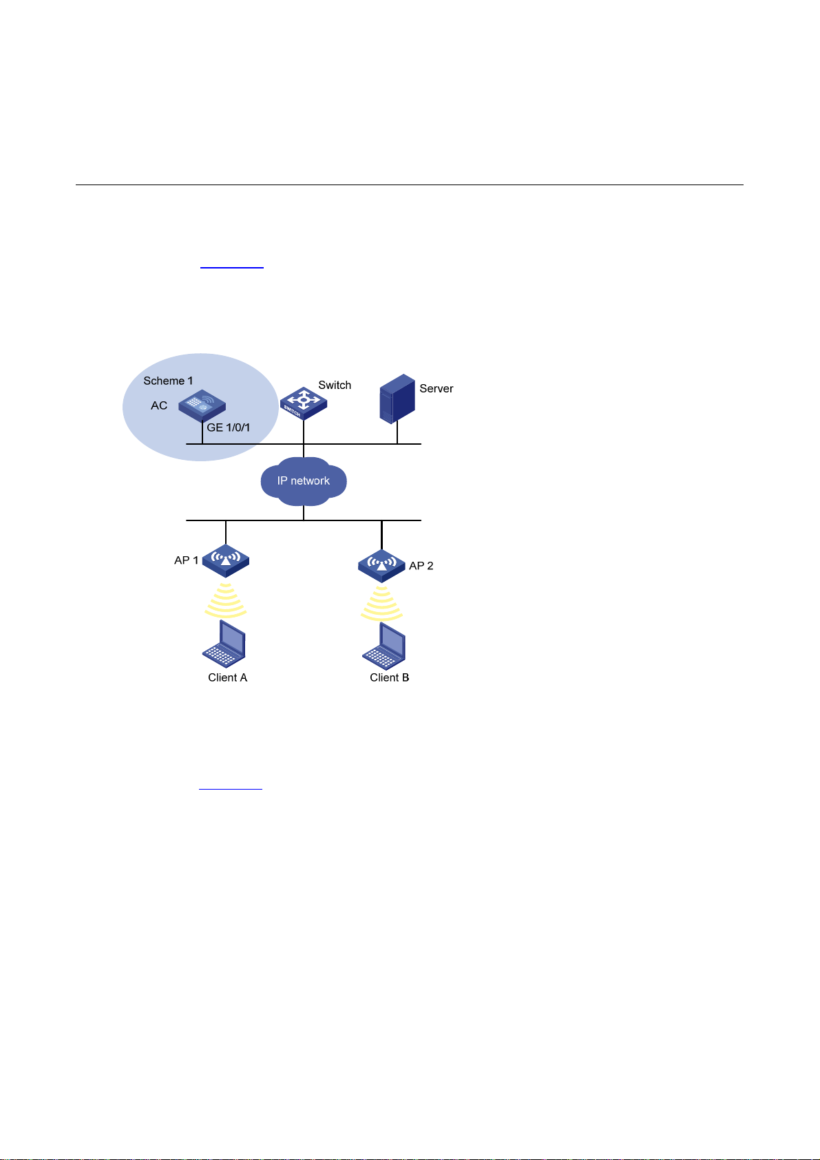
3 Typical Network Scenarios
AC Networking
As shown in Figure 3-1, AC is connected to a switch (Layer 2 or Layer 3), which can be connected to
APs directly or connected to AP s over a network, and Clients can be connected to the network through
APs to implement WLAN user access.
Figure 3-1 AC networking
Access Controller Module Networking
As shown in Figure 3-2, installed with an access controller module, Switch (Layer 2 or Layer 3) can be
connected to APs directly or connected to APs over a network, and Clients can be connected to the
network through the APs to implement WLAN user access.
3-1
Page 23
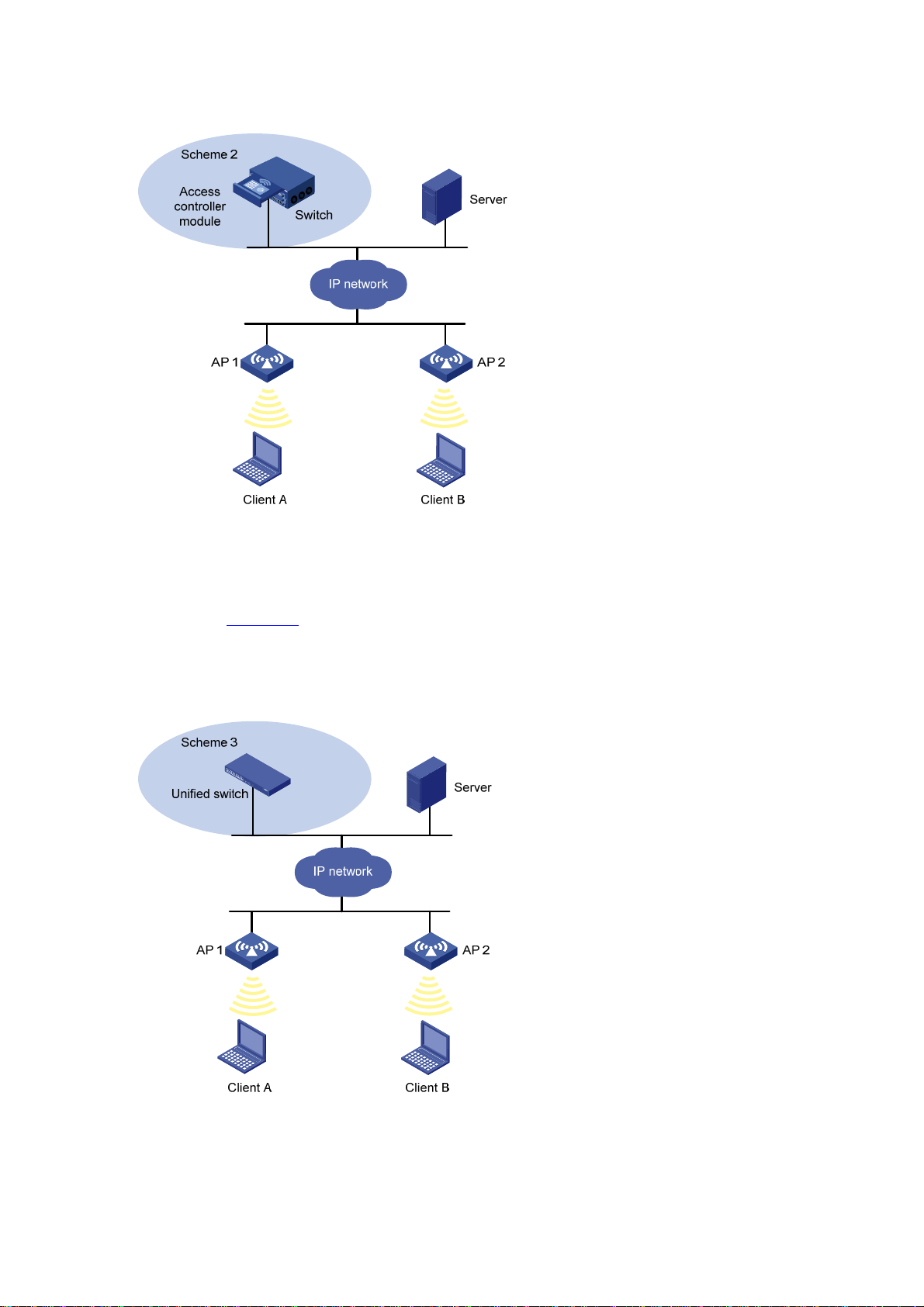
Figure 3-2 Access controller module networking
Unified Switch Networking
As shown in Figure 3-3, Unified switch can be connected to APs directly or connected to APs over a
network, and Clients can be connected to the network through the APs to implement WLAN user
access.
Figure 3-3 Unified switch networking diagram
3-2
Page 24

4 Feature Matrixes
Feature Matrix for the WX5000 Series
The LS8M1WCMA0, LSWM1WCM10, and LSWM1WCM20 on the WX5000 series adopt the OAP
architecture. Installed on the expansion slots of switches, they work as OAP cards to exchange data,
status and control information with the switches through their internal service interfaces. Do not
configure services such as QoS, rate limiting and 802.1X authentication on GE interfaces on the
LS8M1WCMA0, XGE 1/0/1 on the LSWM1WCM10, and the logical interface BAGG1 aggregated by
GE1/0/1 and GE1/0/2 on the LSWM1WCM20.
Table 4-1 Feature matrix for the WX5000 series
Module Feature WX5002 WX5002V2
Summary Summary
Device
License
File
managem
ent
Interface
managem
ent
IPv6
supported
The
WX5002
supports
32
concurrent
APs by
default,
and can be
extended
to support
64
concurrent
APs.
Flash
supported
Configurati
on of IPv6
address for
an
interface is
supported.
IPv6
supported
The
WX5002V2
supports
32
concurrent
APs by
default,
and can be
extended
to support
64
concurrent
APs.
CF
supported
Configurati
on of IPv6
address for
an
interface is
supported.
LS8M1WC
MA0
IPv6
supported
Not
supported
Flash
supported
Configurati
on of IPv6
address for
an
interface is
supported.
WX5004
IPv6
supported
The
WX5004
supports
64
concurrent
APs by
default,
and can be
extended
to support
256
concurrent
APs.
CF
supported
Configurati
on of IPv6
address for
an
interface is
supported.
LSWM1W
CM10
IPv6
supported
The
LSWM1W
CM10
supports
64
concurrent
APs by
default,
and can be
extended
to support
256
concurrent
APs.
CF
supported
Configurati
on of IPv6
address for
an
interface is
supported.
LSWM1W
CM20
IPv6
supported
The
LSWM1W
CM20
supports
32
concurrent
APs by
default,
and can be
extended
to support
128
concurrent
APs.
Flash
supported
Configurati
on of IPv6
address for
an
interface is
supported.
4-1
Page 25

Module Feature WX5002 WX5002V2
LS8M1WC
MA0
WX5004
LSWM1W
CM10
LSWM1W
CM20
Network
Port
mirroring
SNMP
Loopback
test
IPv6
routing
Diagnostic
tools
Remote
port
mirroring
and
cross-boar
d mirroring
not
supported
Configurati
on of IPv6
destination
addresses
is
supported
Supported
on GE
interfaces
Supported Supported Supported Supported Supported Supported
IPv6 ping
supported
Remote
port
mirroring
and
cross-boar
d mirroring
not
supported
Configurati
on of IPv6
destination
addresses
is
supported
Supported
on GE
interfaces
IPv6 ping
supported
Not
supported
Configurati
on of IPv6
destination
addresses
is
supported
Internal
loopback
testing
supported
on GE
interfaces
only
IPv6 ping
supported
Remote
port
mirroring
and
cross-boar
d mirroring
not
supported
Configurati
on of IPv6
destination
addresses
is
supported
Supported
on GE
interfaces
IPv6 ping
supported
Not
supported
Configurati
on of IPv6
destination
addresses
is
supported
Internal
loopback
testing
supported
on XGE
interfaces
only
IPv6 ping
supported
Not
supported
Configurati
on of IPv6
destination
addresses
is
supported
Internal
loopback
testing
supported
on GE
interfaces
only
IPv6 ping
supported
QoS
Advanced
High
availability
ACL IPv6 Supported Supported Supported Supported Supported Supported
Line rate Supported Supported Supported Supported Supported Supported
AC
backup
Stateful
failover
Supported Supported Supported Supported Supported
Not
supported
Supported
Not
supported
Feature Matrix for the WX6000 Series
The switch interface module on the WX6103, and the LSQM1WCMB0, LSBM1WCM2A0, and
LSRM1WCM2A1 access controller modules on the WX6000 series adopt the OAP architecture.
Installed on the expansion slots of switches, they work as OAP cards to exchange data, status and
control information with the switches through their internal service interfaces. The XGE interfaces on
the switch interface module on the WX6103, and the LSQM1WCMB0, LSBM1WCM2A0, and
LSWM1WCM10 access controller modules are internal interfaces. Therefore, you are not
recommended to configure services such as QoS rate limiting and 802.1X authentication on them.
Supported Supported
Not
supported
Not
supported
4-2
Page 26

Table 4-2 Feature matrix for the WX6000 series
Module Feature WX6103 LSQM1WCMB0 LSBM1WCM2A0 LSRM1WCM2A1
Summary Summary
License
File
manageme
nt
Interface
Device
manageme
nt
Port
mirroring
SNMP
IPv6
supported
The
WX6103
supports 128
concurrent
APs by
default, and
can be
extended to
support 640
concurrent
APs.
CF and USB
supported
Configuratio
n of IPv6
address for
an interface
is supported.
Not
supported
Configuratio
n of IPv6
destination
addresses is
supported
IPv6 supported IPv6 not supported IPv6 supported
The
LSQM1WCMB0
supports 128
concurrent APs by
default, and can
be extended to
support 640
concurrent APs.
CF and USB
supported
Configuration of
IPv6 address for
an interface is
supported.
Not supported Not supported Not supported
Configuration of
IPv6 destination
addresses is
supported
The
LSBM1WCM2A0
supports 128
concurrent APs by
default, and can be
extended to support
640 concurrent APs.
CF and USB
supported
Configuration of
IPv6 address for an
interface is not
supported.
Configuration of
IPv6 destination
addresses is not
supported
The
LSRM1WCM2A1
supports 128
concurrent APs by
default, and can be
extended to support
640 concurrent APs.
CF and USB
supported
Configuration of IPv6
address for an
interface is
supported.
Configuration of IPv6
destination
addresses is
supported
Internal
loopback
Loopback
test
IPv6
Network
QoS
Advanced AC backup Supported Supported Supported Supported
High
availability
routing
Diagnostic
tools
ACL IPv6 Supported Supported Not supported Supported
Line rate Supported Supported Supported Supported
Stateful
failover
testing
supported
on XGE
interfaces
only
Supported Supported Not supported Supported
IPv6 ping
supported
Supported Supported Supported Supported
Internal loopback
testing supported
on XGE interfaces
only
IPv6 ping
supported
Internal loopback
testing supported on
XGE interfaces only
IPv6 ping not
supported
Internal loopback
testing supported on
XGE interfaces only
IPv6 ping supported
4-3
Page 27

Feature Matrix for the WX3000 Series
The access controller engine and switching engine on the WX3000 series adopt the OAP architecture.
The switching engine is integrated on the access controller engine as an OAP card. You actually log in
to the access controller engine when you log in to the device by default. GE 1/0/1 interfaces on the
WX3024, WX3010 and WX3008 are used to exchange data, status and control information with
GE1/0/29 (WX3024), GE1/0/11 (WX3010) or GE1/0/9 (WX3008) on the switching engine. Therefore,
you are not recommended to configure services such as QoS rate limiting and 80 2.1X authentication on
these interfaces.
Table 4-3 Feature matrix for the WX3000 series
Module Feature WX3024 WX3010 WX3008
Summary Summary IPv6 not supported IPv6 not supported IPv6 not supported
The WX3024
License
supports 24
concurrent APs by
default, and can
be extended to
support 48
concurrent APs.
The WX3010 supports 12
concurrent APs by default,
and can be extended to
support 24 concurrent
APs.
Not supported
File
management
Device
Network
QoS
Advanced AC backup Not supported Not supported Not supported
Interface
management
Port mirroring Not supported Not supported Not supported
SNMP
Loopback test
IPv6 routing Not supported Not supported Not supported
Diagnostic
tools
ACL IPv6 Not supported Not supported Not supported
Line rate Not supported Not supported Not supported
Flash supported Flash supported Flash supported
Configuration of
IPv6 address for
an interface is not
supported.
IPv6 destination
addresses not
supported
Internal loopback
testing supported
on GE interfaces
only
IPv6 ping not
supported
Configuration of IPv6
address for an interface is
not supported.
IPv6 destination
addresses not supported
Internal loopback testing
supported on GE
interfaces only
IPv6 ping not supported IPv6 ping not supported
Configuration of IPv6
address for an interface is
not supported.
IPv6 destination
addresses not supported
Internal loopback testing
supported on GE
interfaces only
High
availability
Stateful failover Not supported Not supported Not supported
4-4
Page 28

5 Quick Start
The sample output in this manual was created on the WX5004. The output on your device may
vary.
The grayed out functions or parameters on the Web interface indicate that they are not supported
or cannot be modified.
The models listed in this manual are not applicable to all regions. Please consult your local sales
office for the models applicable to your region.
Overview
The Quick Start wizard will lead you through the following configuration steps to make your device
available for use:
Basic Configuration
Admin Configuration
IP Configuration
Wireless Configuration
RADIUS Configuration
Portal Configuration
Encryption Configuration
Guest Wireless Network Configuration
AP Configuration
Quick Start
Home Page of the Quick Start Wizard
From the navigation tree, select Quick St art to enter the home page of the Q uick St art wizard, as shown
in Figure 5-1
.
5-1
Page 29

Figure 5-1 Home page of the Quick Start wizard
Basic Configuration
On the Quick Start wizard page, click start to enter the basic configuration page, as shown in Figure
5-2.
5-2
Page 30
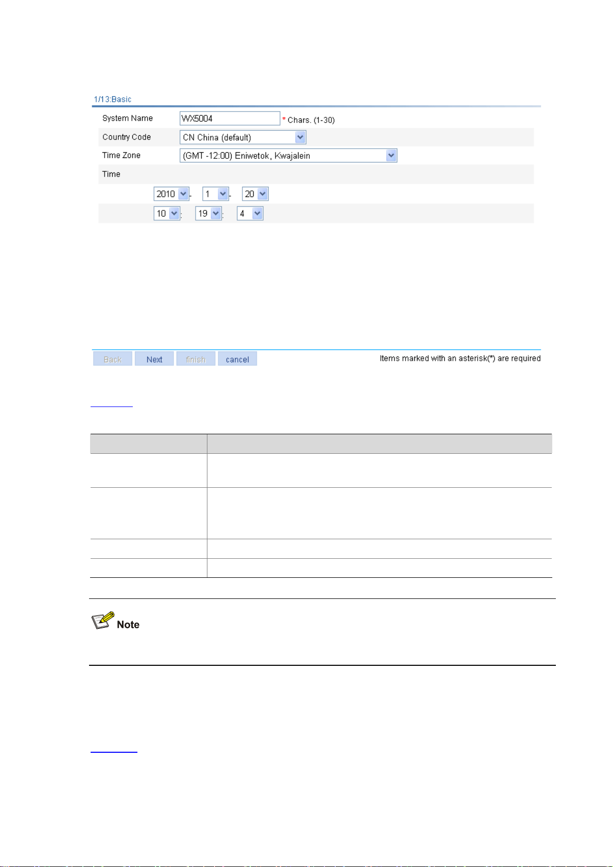
Figure 5-2 Basic configuration page
Table 5-1
lists the configuration items of the basic configuration page.
Table 5-1 Configuration items of the basic configuration page
Item Description
System Name
Country Code
Time Zone Select a time zone for the system.
Time Specify the current time and date.
Specify the name of the current device.
By default, the system name of the device is H3C.
Select the code of the country where you are. This field defines the radio frequency
characteristics such as the power and the total number of channels for frame
transmission. Before configuring the device, you need to configure the country
code correctly.
If the Country Code field is grayed out, it cannot be modified.
Admin Configuration
On the basic configuration page, click Next to enter the Admin Configuration page, as shown in
Figure 5-3
.
5-3
Page 31

Figure 5-3 Admin Configuration page
Table 5-2
lists the configuration items of the Admin Configuration page.
Table 5-2 Configuration items of the Admin Configuration page
Item Description
Password Specify the password used by the user to log in to the device. The default user is admin.
Confirm Password Type the password again to confirm the password.
IP Configuration
On the Admin Configuration page, click Next to enter the IP configuration page, as shown in Figure
5-4.
5-4
Page 32

Figure 5-4 IP configuration page
Table 5-3
lists the configuration items of the IP configuration page.
Table 5-3 Configuration items of the IP configuration page
Item Description
IP Address
Mask
Default Gateway
Wireless Configuration
On the IP configuration page, click Next to enter the wireless configuration page, as shown in Figure
5-5.
Specify the IP address of VLAN-interface 1. This IP address is used for logging into
the device.
The default is 192.168.0.100.
Specify the IP address mask of VLAN-interface 1.
By default, the mask is 24-bit long.
Specify the IP address of the next hop of the default route to the network.
By default, no gateway is available.
5-5
Page 33

Figure 5-5 Wireless configuration page
Table 5-4
lists the configuration items of the wireless configuration p age.
Table 5-4 Configuration items of the wireless configuration page
Item Description
Primary Service
Authentication type
Wireless Service Specify the Service Set Identifier (SSID).
Encrypt
RADIUS Configuration
On the wireless configuration page, select User authentication (802.1X) or Portal for the Primary
Service Authentication Type field, and then click Next to enter the RADIUS configuration page, as
shown in Figure 5-6
.
Select the authentication type for the wireless service, which can be:
None: Performs no authentication.
User authentication (802.1X): Performs 802.1X authentication.
Portal: Performs Portal authentication.
Select this check box to go to the
By default, no encryption is performed. If this option is not selected, the
Encryption Configuration
7/13: Encryption Configuration
step is skipped.
step.
7/13:
5-6
Page 34

Figure 5-6 RADIUS configuration page
Table 5-5
lists the configuration items of the RADIUS configuration page.
Table 5-5 Configuration items of the RADIUS configuration page
Item Description
Select the type of the RADIUS server.
Two types are available: standard and enhanced:
extended: Specifies extended RADIUS server, which is usually a CAMS iMC.
In this case, the RADIUS client (access device) and the RADIUS server
Service Type
Authentication IP Type the IP address of the RADIUS authentication server.
Authentication UDP Port Type the port number of the RADIUS authentication server.
Authentication Key Type the shared key of the RADIUS authentication server.
Accounting IP Type the IP address of the RADIUS accounting server.
Accounting UDP Port Type the port number of the RADIUS accounting server.
Accounting Key Type the shared key of the RADIUS accounting server.
exchange packets based on the specifications and packet format definitions of
a private RADIUS protocol.
standard: Specifies the standard RADIUS server. In this case, the RADIUS
client (access device) and the RADIUS server exchange packets based on the
specifications and packet format definitions of the standard RADIUS protocols
(RFC 2138, RFC 2139, and the updates).
Portal Configuration
On the wireless configuration page, select Portal for the Primary Service Authentication Type field,
and then click Next to enter the RADIUS configuration page. After you com plete RADIUS configuration,
click Next to enter the portal configuration page, as shown in Figure 5-7
.
5-7
Page 35

Figure 5-7 Portal configuration page
Table 5-6
lists the configuration items of the portal configuration page.
Table 5-6 Configuration items of the portal configuration page
Item Description
Server-name Specify the system name of the portal server.
Server-IP Type the IP address of the portal server.
Port Type the port number of the portal server.
Redirect-URL Type the URL of the portal authentication server.
Specify the portal authentication method to be used, which can be:
Direct: Before authentication, a user manually configures an IP address or
directly obtains a public IP address through DHCP, and can access only the
portal server and predefined free websites. After passing authentication, the
user can access the network resources. The authentication process of direct
Method
authentication is relatively simple than that of the re-DHCP authentication.
Layer3: Layer 3 authentication is similar to direct authentication but allows
Layer 3 forwarding devices to be present between the authentication client and
the access device.
Redhcp: Before authentication, a user gets a private IP address through DHCP
and can access only the portal server and predefined free websites. After
passing authentication, the user is allocated a public IP address and can
access the network resources.
5-8
Page 36

Encryption Configuration
You may enter the encryption configuration page in two ways:
On the wireless configuration page, select User authentica tion (802.1X) for the Primary Service
Authentication Type field and click Next to enter the RADIUS configuration page. Complete
RADIUS configuration and then click Next.
On the wireless configuration page, select Portal for the Primary Service Authentication Type
field and click Next to enter the RADIUS configuration page. Complete RADIUS configuration and
click Next to enter the portal configuration page. Then, complete portal authentication and click
Next.
The encryption configuration page is as shown in Figure 5-8
Figure 5-8 Encryption configuration page
.
Table 5-7
lists the configuration items of the encryption configuration page.
5-9
Page 37

Table 5-7 Configuration items of the encryption configuration page
Item Description
Select whether to use an automatically provided WEP key.
Enable: Use an automatically provided WEP key.
Disable: Use a static WEP key.
By default, a static WEP key is used.
Provide Key
Automatically
WEP
Key ID
Key Length
WEP Key Type the WEP key.
If you select to use an automatically provided WEP key, WEP104 will be selected
as the WEP key type.
If you want to select Enable from this drop-down list, you must first select the User
authentication (802.1X) option from the Primary Service Authentication type
drop-down list on the wireless configuration page.
Select the key type of the WEP encryption mechanism, which can be WEP40,
WEP104, and WEP 128.
Select the WEP key index, which can be 1, 2, 3, or 4. Each number represents one
of the four static keys of WEP. The selected key index will be used for frame
encryption and decryption
Select the key length.
When the key type is WEP40, the key length can be five alphanumeric
characters or ten hexadecimal characters.
When the key type is WEP104, the key length can be 13 alphanumeric
characters or 26 hexadecimal characters.
When the key type is WEP128, the key length can be 16 alphanumeric
characters or 32 hexadecimal characters.
Guest Wireless Network Configuration
On the encryption configuration page, click Next to enter the guest wireless network configuration page,
as shown in Figure 5-9
.
5-10
Page 38

Figure 5-9 Guest wireless network configuration page
Select the Create Guest service check box to display the guest service configuration page, as show n
in Figure 5-10
.
Figure 5-10 Guest service configuration page
Table 5-8
lists the configuration items of the guest service configuration page.
5-11
Page 39

Table 5-8 Configuration items of the guest service configuration page
Item Description
Select the guest authentication service authentication type, which can be:
None: Performs no authentication.
User authentication (802.1X): Performs 802.1X authentication. If you select
this option and click Next, you will enter the RADIUS configuration page. For
Guest Service
Authentication type
Wireless Type the access SSID of the guest.
Default VLAN Type the default VLAN ID of the guest.
RADIUS configuration information, refer to RADIUS Configuration.
Portal: Performs portal authentication. If you select this option and click Next,
you can enter the RADIUS configuration page to perform RADIUS
configurations. Then, you can click Next on the RADIUS configuration page to
enter the portal configuration page. For RADIUS configuration information,
refer to RADIUS Configuration
Portal Configuration
.
. For portal configuration information, refer to
Encrypt
Create Guest Vlan Create VLANs for guest users.
AP Configuration
On the guest service configuration page, click Next to enter the AP configuration page, as shown in
Figure 5-1 1
existing APs.
Figure 5-11 AP configuration page
. You can configure an AP and clic k Add. The section at the bottom of the page displays all
Select the
page. For encryption configuration information, refer to Encryption Configuration
Encrypt
check box and click
Next
to enter the encryption configuration
.
Table 5-9
lists the configuration items of the AP configuration page.
5-12
Page 40

Table 5-9 Configuration items of the AP configuration page
Item Description
AP Name Specify the name of the AP connected with the access controller (AC).
Model Specify the type of the AP connected with the AC.
Specify the sequence number of the AP connected with the AC.
Auto
If the
Serial ID
Radio Specify the radio.
Mode The value of this item depends on the type of the AP and the radio.
Channel
Power
also select the
can connect with the AC automatically. If there are a large number of APs, you can enable the
automatic AP discovery function to relieve yourself of the burden to configure the AP sequence
numbers.
Select the channel to be used. Channel number is selected based on the country code and
radio mode. The channel list varies with device models.
Auto: The channel is automatically selected by the device.
After the channel is changed, the corresponding power column will be refreshed automatically.
Select the transmission power.
The maximum transmission power depends on the country code, channel, AP model, radio
mode, and antenna type. If the 802.11n radio mode is applied, the maximum transmission
power also depends on the bandwidth mode.
check box is not selected, you need to manually type a sequence number. You can
Auto
check box to enable the automatic AP discovery function so that the AP
You can configure multiple APs on the page.
Configuration Summary
On the AP configuration p a ge, cli ck Next to enter the configuration summary page, as shown in Figure
5-12. The configuration summary page will display all configurations you have made. Click finish to
apply your configurations.
Figure 5-12 Configuration summary page
5-13
Page 41

6 Web Overview
Support of the H3C WX series access controllers for features may vary by device model. For more
information, see "Feature Matrixes" in Compatibility Matrixes.
The sample output in this manual was created on the WX5004. The output on your device may
vary.
The grayed out functions or parameters on the Web interface indicate that they are not supported
or cannot be modified.
The models listed in this manual are not applicable to all regions. Please consult your local sales
office for the models applicable to your region.
Overview
Hangzhou H3C Technologies Co., Ltd. (hereinafter referred to as H3C) provides the Web-based
network management function to facilitate the operations and maintenance on H3C’s network devices.
Through this function, the administrator can visually manage and maintain network device s through the
Web-based configuration interfaces.
Figure 6-1
Figure 6-1 Web-based network management operating environment
shows a Web-based network management operating environment:
Logging In to the Web Interface
The device is provided with the default Web login information. Y ou can use the default information to log
in to the Web interface. The default Web login information is:
Username: admin
Password: admin
IP address of the device: 192.168.0.100.
You can follow the steps below to log in to the device through the Web interface.
1) Connect the device and PC
Connect the Ethernet interface of the device to the PC using a crossover Ethernet cable.
6-1
Page 42

2) Configure an IP address for the PC and ensure that the PC and device can communicate with each
other properly.
Modify the IP address of the PC to one that within the network segment 192.168.0.0/24 (except for
192.168.0.100), for example, 192.168.0.2.
3) Open the browser, and input the login information.
On the PC, open the browser, type the IP address htt p://192.168.0. 100 in the address bar, press Enter
and you can enter the login page of the Web interface, as shown in Figure 6-2
. Input the username
admin and password admin, and the verification code, select the language (English and Chinese are
supported at present), and click Login.
Figure 6-2 Login page of the Web interface
The PC where you configure the device is not necessarily the Web-based network management
terminal. A Web-based network management terminal is a PC (or another terminal) used to log in
to the Web interface and is required to be reachable to the device.
After logging in to the Web interface, you can create a new user and configure the IP address of the
interface connecting the user and the device.
If you click the verification code displayed on the Web login page, you can get a new verification
code.
Up to five users can concurrently log in to the device through the Web interface.
Logging Out of the Web Interface
Click Logout in the upper-right corner of the Web interface to quit Web-based network management.
The system will not save the current configuration before you log out of the Web interface. Therefore,
you are recommended to save the current configuration before logout.
Introduction to the Web Interface
The Web interface is composed of three parts: navigation tree, title area, and body area, as shown in
Figure 6-3
.
6-2
Page 43

Figure 6-3 Web-based configuration interface
(1) Navigation area (2) Body area (3) Title area
Navigation area: Organizes the Web-based NM function menus in the form of a navigation tree,
where you can select function menus as needed. The result is displayed in the b ody area.
Body area: The area where you can configure and display a function.
Title area: On the left, displays the path of the current configuration interface in the navigation area;
on the right, provides the Save button to quickly save the current configuration, the Help button to
display the Web related help information, and the Logout button to log out of the Web interface.
The Web network management functions not supported by the device will not be displayed in the
navigation area.
Web User Level
Web user levels, ranging from low to high, are visitor, monitor, configure, and management. A user
with a higher level has all the operating rights of a user with a lower level.
Visitor: Users of this level can perform the ping and traceroute operations, but they can neither
access the device data nor configure the device.
Monitor: Users of this level can only access the device data but cannot configure the device.
Configure: Users of this level can access data from the device and configure the device, but they
cannot upgrade the host software, add/delete/modify users, or back up/ restore the ap plicatio n file.
Management: Users of this level can perform any operations for the device.
6-3
Page 44

Introduction to the Web-Based NM Functions
Table 6-1 describes the Web-based network management functions in detail.
Support for the configuration items depends on the device model. For more information, see
Compatibility Matrixes.
User level in Table 6-1 indicates that users of this level or users of a higher level can perform the
corresponding operations.
Table 6-1 Description of Web-based NM functions
Function menu Description User level
Quick Start
Device Info
Wlan Service
Summary
AP
Client
Device License
Allows you to perform quick
configuration of the device.
Displays and refreshes system
resource state, device information,
device interface information, and
recent system operation logs.
Displays the information of the
queried WLAN service, including the
detailed information, statistics, and
connection history.
Displays the information of the
queried AP, including wireless
service, connection history, radio, and
detailed information.
Allows you to reboot an AP. Configure
Displays the detailed information,
statistics, and roaming information of
the client.
Allows you to clear statistics of the
client, disconnect the connection, and
add the client into the blacklist.
Displays license information. Monitor
Configure
Monitor
Monitor
Monitor
Monitor
Configure
6-4
Page 45

Function menu Description User level
Allows you to add licenses. Configure
Basic
Device
Maintenance
System Time
Syslog
Set sysname
Set idle
timeout
Software
Upgrade
Reboot Allows you to reboot the device. Management
Diagnostic
Information
Loglist
Loghost
Logset
Displays and allows configuration of
the system name.
Displays and allows configuration of
the idle timeout period for a logged-in
user.
Allows you to upload the file to be
upgraded from the local host to
upgrade the system software.
Allows you to generate a diagnostic
information file, view the file or save
the file to the local host.
Displays and allows configuration of
the system date and time.
Displays and refreshes system logs. Monitor
Allows you to clear system logs. Configure
Displays and allows configuration of
the loghost.
Displays and allows configuration of
the buffer capacity, and refreshes
interval for displaying system logs.
Configure
Configure
Management
Management
Configure
Configure
Configure
Backup
Configuration
management
File management
Interface Management
Port Mirroring
Restore
Save
Initialize
Summary
Allows you to back up the
configuration file for the next startup
to the host of the current user.
Allows you to upgrade the
configuration file on the host of the
current user to the device for the next
startup.
Allows you to save the current
configuration to the configuration file
for the next startup.
Allows you to restore the system to
factory defaults.
Allows you to manage files on the
device, including displaying file list,
downloading a file, uploading a file,
and removing a file.
Displays interface information and
statistics.
Allows you to create, modify, delete,
and enable/disable an interface, and
clear interface statistics.
Displays the configuration information
of a port mirroring group.
Management
Management
Configure
Configure
Management
Monitor
Configure
Monitor
Create
Remove
Allows you to create a port mirroring
group.
Allows you to remove a port mirroring
group.
6-5
Configure
Configure
Page 46

Function menu Description User level
User
Management
Modify Port
Summary
Super
Password
Create
Modify
Remove
Switch To
Management
Setup
Community
Allows you to configure ports for a
mirroring group.
Displays brief information of FTP and
Telnet users.
Allows you to configure the password
for a lower-level user to switch from
the current access level to the
management level.
Allows you to create an FTP or Telnet
user.
Allows you to modify FTP or Telnet
user information.
Allows you to remove an FTP or a
Telnet user.
Allows you to switch the current user
level to the management level.
Displays and refreshes SNMP
configuration and statistics
information.
Allows you to configure SNMP. Configure
Displays SNMP community
information.
Allows you to create, modify and
delete an SNMP community.
Configure
Monitor
Management
Management
Management
Management
Monitor
Monitor
Monitor
Configure
SNMP
Loopback Test
Group
User
Trap
View
Displays SNMP group information. Monitor
Allows you to create, modify and
delete an SNMP group.
Displays SNMP user information. Monitor
Allows you to create, modify and
delete an SNMP user.
Displays the status of the SNMP trap
function and information about target
hosts.
Allows you to enable or disable the
SNMP trap function, or create, modify
and delete a target host.
Displays SNMP view information. Monitor
Allows you to create, modify and
delete an SNMP view.
Allows you to perform the loopback
test on Ethernet interfaces.
Configure
Configure
Monitor
Configure
Configure
Configure
6-6
Page 47

Function menu Description User level
Network
MAC
VLAN
ARP
Management
MAC
Config
VLAN
Port
ARP Table
Gratuitous
ARP
Displays MAC address information. Monitor
Allows you to create or remove MAC
addresses.
Displays and allows configuration of
MAC address aging time.
Displays all VLANs on the device and
information about their member ports.
Allows you to create, modify and
delete VLANs.
Displays VLANs to which a port on
the device belongs.
Allows you to modify the VLANs to
which a port belongs.
Displays ARP table information. Monitor
Allows you to add, modify or delete an
ARP entry.
Displays configuration information of
gratuitous ARP.
Allows you to configure gratuitous
ARP.
Configure
Configure
Monitor
Configure
Monitor
Configure
Configure
Monitor
Configure
ARP
Anti-Attack
IGMP
Snooping
ARP
Detection
Advanced
Configuration
Basic
Advance
Displays the configuration information
of ARP detection.
Allows you to configure ARP
detection.
Displays the configuration information
of source MAC address based ARP
attack detection, ARP active
acknowledgement, and ARP packet
source MAC address consistency
check.
Allows you to configure source MAC
address based ARP attack detection,
ARP active acknowledgement, and
ARP packet source MAC address
consistency check.
Displays global IGMP Snooping
configuration information and the
IGMP Snooping configuration
information in a VLAN, and allows you
to view the IGMP Snooping multicast
entry information.
Allows you configure IGMP Snooping
globally and in a VLAN.
Displays the IGMP Snooping
configuration information on a port.
Allows you to configure IGMP
Snooping on a port.
Monitor
Configure
Monitor
Configure
Monitor
Configure
Monitor
Configure
IPv4 Routing
Summary Displays the IPv4 active route table. Monitor
Create
Allows you to create an IPv4 static
route.
6-7
Configure
Page 48

Function menu Description User level
IPv6 Routing
DHCP
Remove
Summary Displays the IPv6 active route table. Monitor
Create
Remove
DHCP Server
DHCP Relay
Allows you to delete the selected IPv4
static routes.
Allows you to create an IPv6 static
route.
Allows you to delete the selected IPv6
static routes.
Displays the DHCP service status,
the DHCP address pool information,
and the DHCP server status on an
interface.
Allows you to set the DHCP service
status, add, modify, or delete a DHCP
address pool, and modify the DHCP
server status on an interface.
Displays the status of a DHCP service
and advanced configuration
information of DHCP relay, displays
information of a DHCP group, and
status of the DHCP relay agent on an
interface, and allows you to view the
DHCP relay user information.
Allows you to configure the status of a
DHCP service and advanced
configuration information of DHCP
relay, add or delete a DHCP group,
and modify the status of the DHCP
relay agent on an interface.
Configure
Configure
Configure
Monitor
Configure
Monitor
Configure
DHCP
Snooping
Static Domain
Name
Resolution
DNS
Service Management
Diagnostic
Tools
Dynamic
Domain Name
Resolution
IPv4 Ping
Displays the status of the DHCP
Snooping function, and the trusted
and untrusted attributes of a port, and
allows you to view the DHCP
Snooping user information.
Allows you to configure the status of
the DHCP Snooping function, and
modify the trusted and untrusted
attributes of a port.
Allows you to display, create, modify
or delete a static host name-to-IP
address mapping.
Displays and allows configuration of
related parameters for dynamic
domain name resolution. Allows you
to display, create, or delete an IP
address and the domain name suffix.
Displays the states of the services:
enabled or disabled.
Specifies whether to enable various
services, and sets related
parameters.
Allows you to ping an IPv4 address or
host and display the result.
Monitor
Configure
Configure
Configure
Configure
Management
Visitor
IPv6 Ping
Allows you to ping an IPv6 address or
host and display the result.
6-8
Visitor
Page 49

Function menu Description User level
AP
AP Setup
Auto AP
AP Group
Access Service
Trace Route
Allows you to perform trace route
operations and display the result.
Displays AP-related information,
including AP name, AP IP address,
serial ID, model and status.
Allows you to add an AP and modify
the AP configuration.
Displays auto AP information after
auto AP is enabled, including AP
name, model, serial ID and IP
address.
Enables auto AP. Configure
Displays AP group information. Monitor
Allows you to create and configure an
AP group.
Displays an access service, including
security type, detailed information,
service status and binding status.
Allows you to create and configure an
access service, map an access
service to an AP radio, and add a
MAC authentication list.
Visitor
Monitor
Configure
Monitor
Configure
Monitor
Configure
WLAN Service
Roam
Mesh Service
Roam Group
Client Information
Mesh Service
Mesh Policy
Mesh Global
Setting
Displays a mesh service and its
status.
Allows you to create and configure a
mesh service, including security
settings.
Displays mesh policies. Monitor
Allows you to create and configure a
mesh policy.
Displays mesh global setting,
including basic setting and mesh
portal service.
Allows you to configure mesh global
setting, including basic setting and
mesh portal service.
Displays a roaming group and its
members.
Allows you to configure a roaming
group and add a group member.
Displays client information, including
MAC address, BSSID, VLAN ID,
home AC and roaming direction.
Monitor
Configure
Configure
Monitor
Configure
Monitor
Configure
Monitor
6-9
Page 50

Function menu Description User level
Radio
Radio
Rate
Scan
Calibration
Calibration
Operations
Parameter
Setting
Displays radio status, including radio
mode and radio status.
Allows you to configure radio status,
including 802.11n settings.
Displays rate settings. Monitor
Allows you to configure 802.11n
rates, including MCS index.
Displays channel scanning, including
scanning mode, scanning type and
scanning interval.
Allows you to configure channel
scanning, including scanning mode
and scanning type.
Displays or refreshes AP status,
including channel status, neighbor
information, and history information.
Manual calibration Configure
Displays basic setup, channel setup
and power setup.
Allows you to configure channel
calibration parameters.
Monitor
Configure
Configure
Monitor
Configure
Monitor
Monitor
Configure
Authentication
Antenna
802.1X
Portal
AAA
Portal Server
Free Rule
Domain Setup
Authentication
Allows you to configure the antenna
of an AP.
Displays the global 802.1X
information and 802.1X information of
a port.
Displays the global 802.1X features
and 802.1x features of a port.
Displays the portal server
configuration information.
Allows you to add and delete a portal
server.
Displays the portal-free rule
configuration information.
Allows you to add and delete a
portal-free rule.
Displays ISP domain configuration
information.
Allows you to add and remove ISP
domains.
Displays the authentication method
configuration information of an ISP
domain.
Allows you to specify authentication
methods for an ISP domain.
Configure
Monitor
Configure
Monitor
Configure
Monitor
Configure
Monitor
Management
Monitor
Management
Authorization
6-10
Displays the authorization method
configuration information of an ISP
domain.
Monitor
Page 51

Function menu Description User level
RADIUS
Local EAP Server
Users
Accounting
RADIUS
Server
RADIUS
Setup
Local User
User Group
Guest
Allows you to specify authorization
methods for an ISP domain.
Displays the accounting method
configuration information of an ISP
domain.
Allows you to specify accounting
methods for an ISP domain.
Displays and allows configuration of
RADIUS server information.
Displays and allows configuration of
RADIUS parameters.
Displays the configuration information
of the local EAP service.
Allows you to configure the local EAP
service.
Displays local users’ configuration
information.
Allows you to add, modify, and
remove local users.
Displays user groups’ configuration
information.
Allows you to add, modify, and
remove user groups.
Displays guest users’ configuration
information.
Allows you to add, modify, and
remove guest users.
Management
Monitor
Management
Management
Management
Monitor
Configure
Monitor
Management
Monitor
Management
Monitor
Management
PKI
Displays user profile configuration
User Profile
Entity
Domain
Certificate
CRL Displays the contents of the CRL. Monitor
information.
Allows you to add, modify, remove,
enable, and disable user profiles.
Displays information about PKI
entities.
Allows you to add, modify, and delete
a PKI entity.
Displays information about PKI
domains.
Allows you to add, modify, and delete
a PKI domain.
Displays the certificate information of
PKI domains and allows you to view
the contents of a certificate.
Allows you to generate a key pair,
destroy a key pair, retrieve a
certificate, request a certificate, and
delete a certificate.
Monitor
Configure
Monitor
Configure
Monitor
Configure
Monitor
Configure
6-11
Page 52

Function menu Description User level
WLAN Security
Rogue device
detection
AP Monitor
Rule List
Monitor
Record
History
Record
Allows you to receive the CRL of a
domain.
Displays AP operating mode. Monitor
Allows you to configure AP operating
mode.
Displays list types for the rogue
device detection and the detection
rules.
Allows you to configure list types for
rogue device detection and the rules.
Displays monitor record of rogue
device detection.
Allows you to clear monitor record of
rogue device detection, and add
rogue devices to blacklist.
Displays rogue device detection
history.
Allows you to clear history of rogue
device detection and add rogue
devices to blacklist.
Displays IDS configuration. Monitor
Configure
Configure
Monitor
Configure
Monitor
Configure
Monitor
Configure
WIDS
Blacklist and
White list
WIDS Setup
History
Record
Statistics
Blacklist
White List
Allows you to configure IDS detection,
including flood attack detection,
spoofing attack detection, and weak
IV detection.
Displays IDS attack detection history. Monitor
Allows you to clear history record of
IDS attack detection and add the
detected devices that initiate attacks
to blacklist.
Displays statistics of IDS attack
detection.
Allows you to clear the statistics. Configure
Displays dynamic and static
blacklists.
Allows you to clear dynamic blacklist
and static blacklist; enable dynamic
blacklist; add entries to the static
blacklist.
Displays white list. Monitor
Allows you to clear white list, and add
entries to the white list.
Configure
Configure
Monitor
Monitor
Configure
Configure
Authorized IP
Summary
Setup
Displays the configurations of the
authorized IP, the associated IPv4
ACL rule list, and the associated IPv6
ACL rule list.
Allows you to configure the
authorized IP.
6-12
Management
Configure
Page 53

Function menu Description User level
Allows you to display, add, modify
User Isolation
and remove user isolation
configuration.
Management
QoS
Time Range
ACL IPv4
ACL IPv6
Display
Create Allows you to create a time range. Configure
Delete Allows you to delete a time range. Configure
Display
Create Allows you to create an IPv4 ACL. Configure
Basic Setup
Advanced
Setup
Link Setup
Delete
Display
Create Allows you to create an IPv6 ACL. Configure
Basic Setup
Displays time range configuration
information.
Displays IPv4 ACL configuration
information.
Allows you to configure a rule for a
basic IPv4 ACL.
Allows you to configure a rule for an
advanced IPv4 ACL.
Allows you to create a rule for an
Ethernet frame header ACL.
Allows you to delete an IPv4 ACL or
its rules.
Displays IPv6 ACL configuration
information.
Allows you to configure a rule for a
basic IPv6 ACL.
Monitor
Monitor
Configure
Configure
Configure
Configure
Monitor
Configure
Wireless QoS
Advanced
Setup
Delete
Wireless QoS
Radio
Statistics
Client
Statistics
Allows you to configure a rule for an
advanced IPv6 ACL.
Allows you to delete an IPv6 ACL or
its rules.
Displays wireless QoS, including SVP
mapping, CAC admission policy,
radio EDCA and client EDCA.
Allows you to configure wireless QoS,
including SVP mapping, CAC
admission policy, radio EDCA and
client EDCA.
Displays radio statistics, including
WMM status and detailed radio
information.
Displays radio statistics, including
WMM status and detailed radio
information, and allows you to clear
the radio statistics.
Displays client statistics, including
WMM status and detailed client
information.
Displays client statistics, including
WMM status and detailed client
information, and allows you to clear
the client statistics.
Configure
Configure
Monitor
Configure
Monitor
Configure
Monitor
Configure
6-13
Page 54

Function menu Description User level
Line Rate
Port Priority
Trust Mode
Classifier
Displays the configured client rate
Client Rate
Limit
Display
Setup Allows you to configure the line rate. Configure
Display
Create Allows you to create a class. Configure
Setup
limit information.
Allows you to configure and modify
client rate limiting mode, direction and
rate.
Displays line rate configuration
information.
Displays the priority and trust mode of
a port.
Allows you to modify the priority and
trust mode of a port.
Displays priority trust mode
configuration information.
Allows you to configure the priority
trust mode.
Displays classifier configuration
information.
Allows you to configure the
classification rules for a class.
Configure
Monitor
Monitor
Configure
Management
Management
Monitor
Configure
Behavior
QoS Policy
Port Policy
Delete
Display
Create Allows you to create a traffic behavior. Configure
Setup
Delete Allows you to delete a traffic behavior. Configure
Display
Create Allows you to create a QoS policy. Configure
Setup
Delete
Display
Setup
Allows you to delete a class or its
classification rules.
Displays traffic behavior configuration
information.
Allows you to configure actions for a
traffic behavior.
Displays QoS policy configuration
information.
Allows you to configure the
classifier-behavior associations for a
QoS policy.
Allows you to delete a QoS policy or
its classifier-behavior associations.
Displays the QoS policy applied to a
port.
Allows you to apply a QoS policy to a
port.
Configure
Monitor
Configure
Monitor
Configure
Configure
Monitor
Configure
Service Policy
Delete
Allows you to remove the QoS policy
from the port.
Displays the QoS policy applied to a
WLAN-ESS port.
6-14
Configure
Monitor
Page 55

Function menu Description User level
Advanced
Settings
District code
AC Backup
Load Balancing
AP Setup
Allows you to configure the QoS
policy applied to a WLAN-ESS port.
Displays the district code. Monitor
Allows you to modify the district code. Configure
Displays the address of the backup
Setup
Status Displays the status of the AC. Monitor
AP Version
Switch to fat
AP
AC.
Allows you to configure the address of
the backup AC.
Displays the load balancing mode
and the current connection status.
Allows you to configure the load
balancing mode and refresh the
current connection status.
Displays the AP version, including the
AP model and software version.
Allows you to upgrade the software. Configure
Displays the model and IP address of
the AP.
Switches to fat AP. Configure
Configure
Monitor
Configure
Monitor
Configure
Monitor
Monitor
Displays the AP working mode
Switch to Fat AP
High Reliability Stateful Failover
switching information.
Allows you to switch the working
mode of an AP.
Displays stateful failover information. Monitor
Allows you to modify stateful failover
configuration.
Introduction to the Controls on the Web Pages
Apply button
Click to submit the input information.
Cancel button
Click to cancel the input information. The page changes to the display page of the function or to the
Device Info page.
Search button
Select an item to be queried, input the keyword, and click the Query button to display the items that
meet the requirements.
Monitor
Configure
Configure
The advance search function is also provided. You can click the plus sign before Search Item, as
shown in Figure 6-4
. Y ou can select Match case and whole word, that is, the item to be searched must
completely match the keyword, or you can select Search in previous results. If you do not select exact
search, fuzzy search is performed.
6-15
Page 56

Figure 6-4 Advanced search
Refresh button
Click to refresh the display information of the current page.
Clear button
Click to clear all the items in a list or all statistics.
Remove button
Click to remove the selected items.
Select All button
Click to select all the items in a list, or all the ports on the device panel.
Select None button
Click to deselect all the items in a list, or all the ports on the device panel.
Restore button
Click to restore all the items in the current configuration page to the system default.
icon
Click to enter the modification page of an item to modify the configurations of the item.
icon
Click to delete the item corresponding to this icon.
Help button
Click to open the online help page as shown in Figure 6-5.
6-16
Page 57

Figure 6-5 Help
Sort display
On the page, you can click the blue items of each column to sort and display the records based on the
item you selected.
6-17
Page 58

Figure 6-6 Sort display
Configuration Guidelines
The Web-based configuration interface supports the operating systems of Windows XP, Wind ows
2000, Windows Server 2003 Enterprise Edition, Windows Server 2 003 Standard Edition, Windows
Vista, Linux and MAC OS.
The Web-based configuration interface supports the browsers of Microsoft Internet Explorer 6.0
SP2 and higher, Mozilla Firefox 3.0 and higher, Google Chrome 2.0.174.0 and higher, and the
browser must support and be enabled with JavaScript.
The Web-based configuration interface does not support the Back, Next, Refresh buttons
provided by the browser. Using these buttons may result in abnormal display of Web pages.
When the device is performing the spanning tree calculation, you cannot log in to or use the Web
interface.
As the Windows firewall limits the number of TCP connections, when you use IE to log in to the
Web interface, sometimes you may be unable to open the Web interface. To avoid this problem, it
is recommended to turn off the Windows firewall before login.
If the software version of the device changes, you are recommended to clear the cache data o n the
browser before logging in to the device through the Web interface; otherwise, the Web page
content may not be displayed correctly.
Troubleshooting Web Browser
Cannot Access the Device Through the Web Interface
Symptom
You can ping the device successfully, and log in to the device through telnet. HTTP is enabled and the
operating system and browser version meet the Web interface requirements. However, you cannot
access the Web interface of the device.
6-18
Page 59

Analysis
If you use the Microsoft Internet Explorer, you can access the Web interface only when these
functions are enabled: Run ActiveX controls and plug-ins, script ActiveX controls marked safe for
scripting and active scripting.
If you use the Mozilla Firefox, you can access the Web interface only when JavaScript is enabled.
Configuring the Internet Explorer settings
1) Open the Internet Explorer, and then select Tools > Internet Options.
2) Click the Security tab, and then select a Web content zone to specify its security settings, as
shown in Figure 6-7
.
Figure 6-7 Internet Explorer setting (I)
3) Click Custom Level, and a dialog box Security Settings appears.
4) As shown in Figure 6-8
, set the enable these functions: Run ActiveX controls and plug-ins, script
ActiveX controls marked safe for scripting and active scripting.
6-19
Page 60

Figure 6-8 Internet Explorer Setting (II)
5) Click OK in the Security Settings dialog box.
Configuring Firefox Web browser Settings
1) Open the Firefox Web browser, and then select Tools > Options.
2) Click the Content tab, select the Enable JavaScript check box, and click OK, as shown in Figure
6-9.
6-20
Page 61

Figure 6-9 Firefox Web browser setting
6-21
Page 62

7 Summary
Support of the H3C WX series access controllers for features may vary by device model. For more
information, see "Feature Matrixes" in Compatibility Matrixes.
The sample output in this manual was created on the WX5004. The output on your device may
vary.
The grayed out functions or parameters on the Web interface indicate that they are not supported
or cannot be modified.
The models listed in this manual are not applicable to all regions. Please consult your local sales
office for the models applicable to your region.
Device Information Overview
You can view the following information on the Device Info menu:
Device information
System resource state
Device interface information
Recent system logs
After logging in to the Web interface, you will enter the Summary > Device Info page, as shown in
Figure 7-1
.
7-1
Page 63

Figure 7-1 Device info page
Select the refresh mode from the Refresh Period drop-down box.
If you select a specific period (such as, 1 minute), the system periodically refreshes the Device
Info page according to the specified period;
If you select Manual, you need to click Refresh to refresh the Device info page.
Device Info
Table 7-1 describes the device information configuration items.
Table 7-1 Device information configuration items
Device Name
Product Information
Device Location
Contact Information
Item Description
Displays the device model.
Displays the product information.
Displays the location of the device.
You can set a character string to describe the physical location of the device on
SNMP Setup
the
Displays the contact information for device maintenance.
You can set a character string to describe the contact information for device
maintenance on the
page by selecting
SNMP Setup
Device
>
page by selecting
SNMP
.
Device
>
SNMP
.
SerialNum
Software Version
Hardware Version
Bootrom Version
Displays the serial number of the device.
Displays the software version of the device.
Displays the hardware version of the device.
Displays the Boot ROM version of the device.
7-2
Page 64

Item Description
Running Time
System Resource State
Table 7-2 describes the system resource state configuration items.
Table 7-2 System resource state configuration items
Item Description
CPU Usage
Memory Usage
Temperature Displays the temperature of the device.
Device Interface Information
Table 7-3 describes the device interface information configuration items.
Table 7-3 Device interface information configuration items
Item Description
Display the running time after the latest boot of the device.
Displays the real-time CPU usage.
Displays the real-time memory usage and the total memory.
Interface
IP Address/Mask
Status
To know more information about device interfaces, click the More hyperlink under the Device Interface
Information area to enter the Device > Interface page to view and operate the interfaces. For detailed
information, refer to Interface Management Configuration.
Recent System Logs
Table 7-4 describes the recent system log configuration items.
Displays interface name and interface number.
Displays the IP address and mask of an interface.
Displays interface status.
: The interface is up and is connected.
: The interface is up, but not connected.
: The interface is down.
7-3
Page 65

Table 7-4 Recent system log configuration items
Item Note:
Time
Level
Description
Displays the time when the system logs are generated.
Displays the level of the system logs.
Displays the contents of the system logs.
The device info page only displays at most five recent login and logout logs in all system logs.
To know more information about system logs, click the More hyperlink under the Recent System
Operation Logs area to enter the Device > Syslog > Loglist page to view the logs. For detailed
information, refer to Log Management Configuration of this manual.
Displaying WLAN Service
Select Summary > WLAN Service from the navigation tree, click the specified WLAN service to view
the detailed information, statistics, or connection history.
Displaying Detailed Information of WLAN Service
The detailed information of WLAN service (clear type) is as shown in Figure 7-2. For the description of
the fields in the detailed information, refer to Table 7-5
Figure 7-2 Display detailed information of WLAN service (clear type)
.
7-4
Page 66

Table 7-5 Fields of detailed information of the WLAN service (clear type)
Field Description
Service Template Number Current service template number
SSID Service set identifier (SSID) for the ESS
Binding Interface Name of the interface bound with the service template
Service Template Type Service template type
Authentication Method
SSID-hide
Type of authentication used
WLAN service of the clear type only uses open system authentication
Disable: The SSID is advertised in beacon frames.
Enable: Disables the advertisement of the SSID in beacon frames.
Forwarding mode:
Bridge Mode
Local forwarding: Uses local forwarding in the service template.
Remote forwarding: Uses AC remote forwarding in the service template.
Status of service template:
Service Template Status
Enable: Enables WLAN service.
Disable: Disables WLAN service.
Maximum clients per BSS Maximum number of associated clients per BSS
The detailed information of WLAN service (crypto type) is as sh own in Figure 7-3
the fields in the detailed information, refer to Table 7-6
.
Figure 7-3 Display detailed information of WLAN service (crypto type)
. For the description of
7-5
Page 67

Table 7-6 Fields of detailed information of the WLAN service (crypto type)
Field Description
Service Template Number Current service template number
SSID SSID for the ESS
Binding Interface Name of the interface bound with the service template
Service Template Type Service template type
Security IE Security IE: WPA or RSN
Authentication Method Authentication method: open system or shared key
SSID-hide
Disable: The SSID is advertised in beacon frames.
Enable: Disables the advertisement of the SSID in beacon frames.
Cipher Suite Cipher suite: CCMP, TKIP, WEP40, WEP104, or WEP128
TKIP Countermeasure Time(s) TKIP countermeasure time in seconds
PTK Life Time(s) PTK lifetime in seconds
GTK Rekey GTK rekey configured
GTK Rekey Method GTK rekey method configured: packet based or time based
Time for GTK rekey in seconds
GTK Rekey Time(s)
If Time is selected, the GTK will be refresh ed after a specified period of
time.
If Packet is selected, the GTK will be refreshed after a specified number
of packets are transmitted.
Forwarding mode:
Bridge Mode
Local forwarding: Uses local forwarding in the service template.
Remote forwarding: Uses AC remote forwarding in the service template.
Status of service template:
Service Template Status
Enable: Enables WLAN service.
Disable: Disables WLAN service.
Maximum clients per BSS Maximum number of associated clients per BSS
Displaying Statistics of WLAN Service
The statistics of WLAN service are as shown in Figure 7-4.
7-6
Page 68

Figure 7-4 Display WLAN service statistics
Displaying Connection History Information of WLAN Service
The connection history information of WLAN service is as shown in Figure 7-5.
Figure 7-5 Display the connection history information of WLAN service
Displaying AP
Select Summary > AP from the navigation tree to enter the AP page, as shown in Figure 7-6. You can
display the WLAN service information, connection history, radio and detailed information of an AP by
clicking the tabs on the page.
7-7
Page 69

Displaying WLAN Service Information of an AP
The WLAN service information of an AP is as shown in Figure 7-6.
Figure 7-6 Display WLAN service information
Displaying AP Connection History Information
The connection history information of an AP is as shown in Figure 7-7.
Figure 7-7 Display AP connection history information
Displaying AP Radio Information
Select Summary > AP from the navigation tree to enter the AP page, click the Radio tab on the page,
and click the name of the specified AP to view the radio information of an AP.
The radio information of an AP is as show n in Figure 7-8
statistics, refer to Table 7-7
.
7-8
. For the description of the fields in the AP radio
Page 70

Figure 7-8 Display AP radio information
The Noise Floor item in the table indicates various random electromagnetic waves du ring the wireless
communication. For the environment with a high noise floor, you can improve the signal-to-noise ration
(SNR) by increasing the transmit power or reducing the noise floor.
Table 7-7 Description on the fields of the AP radio information
Field Description
AP name Access point name
Radio Id Radio ID
Transmitted Frames Statistics Statistics of transmitted frames
Total Frames Number of frames transmitted
Unicast Frames Number of unicast frames transmitted
Broadcast/Multicast Frames Number of broadcast or multicast frames transmitted
Discard Frames Number of frames discarded.
Retry Count Number of transmission retries
Multiple Retry Count Number of frames that have been retransmitted
Authentication Frames Number of authentication responses transmitted
7-9
Page 71

Field Description
Failed RTS Number of RTS failed during transmission
Successful RTS Number of RTS transmitted successfully
Failed ACK
Association Frames Number of association responses transmitted
Packet Count Statistics Based on Size
Packet Count Statistics Based on Rate
Packet Count Statistics Based on MCS
Rate
Received Frames Statistics Statistics of received frames
Total Frames Number of frames received
Unicast Frames Number of unicast frames received
Number of transmitted frames for which no acknowledgement is
received
Number of frames counted based on the frame size. The frame size
falls in the following four ranges:
size < 128
128 < size < 512
512 < size < 1024
size > 1024
Numbers of frames counted separately based on their transmit
rates: 802.11a, 802.11b, or 802.11g. Only the numbers of frames
counted based on the data rates supported by the radio of the AP
are displayed. For example, if the radio supports 802.11a, the
number of 802.11a frames is displayed, and numbers of 802.11b
and 802.11g frames will not be displayed.
Numbers of frames counted separately based on their MCS rates.
If the device does not support 802.11n, this field will not be
displayed.
Broadcast/Multicast Frames Number of broadcast or multicast frames received
Fragmented Frames Number of fragmented frames received
FCS Failures Number of frames dropped due to FCS failure
Authentication Frames Number of authentication requests received
Duplicate Frames Number of duplicate frames received
Decryption Errors Number of frames dropped due to decr yption error
Association Frames Number of association requests received
Displaying AP Detailed Information
Select Summary > AP from the navigation tree to enter the AP page, click the Detail tab on the page,
and click the name of the specified AP to view the detailed information of an AP.
The detailed information of an AP is as shown in Figure 7-9
detailed information, refer to Table 7-8
. For the description of the fields in the AP
.
7-10
Page 72

Figure 7-9 Display AP detailed information
Table 7-8 Description on the fields of the AP information
Field Description
APID Access point identifier
AP System Name Access point name
Map Configuration Configuration file mapped to the AP
Current state of the AP:
ImageDownload: The AP is downloading the version. If the ImageDownload
state persists, check the following: 1) The version of the fit AP saved on the AC
matches with the version that the AC requires; 2) The space of the flash is
enough.
Idle: The AP is idle. If the Idle state persists, check the following: 1) If the fields
of Latest Join IP Address and Tunnel Down Reason are displayed as -NA-,
it indicates that the AP has never connected to the AC successfully. You need
to check the network cable, power supply of the fit AP, and the AP serial
State
Up Time(hh:mm:ss)
number if the serial number was manually input. 2) If the fields of Latest Join
IP Address and Tunnel Down Reason are displayed as other contents, it
indicates that the AP has connected to the AC successfully. Refer to the output
of the Tunnel Down Reason field for the detailed reason.
Run: The AP is operating. It indicates that the AP has connected to the AC
successfully. If the AC backup function is enabled, this field also displays the
main or backup state of the AC. Run(M) indicates that the AC is a main AC, and
Run(B) indicates a backup AC.
Config: The AC is delivering configuration file to the fit AP, and the fit AP is
collecting radio information through the radio interface and reporting to the AC.
This state is an instantaneous state.
Time duration for which the AP has been connected to the AC. NA indicates AP is
not connected to the AC.
Model AP model name
Serial-ID Serial ID of the AP
IP Address IP address of the AP
H/W Version Hardware version of the AP
7-11
Page 73

Field Description
S/W Version Software version of the AP
Boot-Rom version Boot ROM version of the AP
Description Description of the AP
Connection Type AP connection type: “Master” or “Backup”
Peer AC MAC Address Peer AC MAC address in cas e of AC backu p
Priority Level AP connection priority
Echo Interval(s) Interval for sending echo requests, in seconds
Statistics report
Interval(s)
Interval for sending statistics information messages, in seconds
Cir (Kbps) Committed information rate in kbps
Cbs (Bytes) Committed burst size in bytes
Jumboframe Threshold Threshold value of jumbo frames
Transmitted control
packets
Number of transmitted control packets
Received control packets Number of received control packets
Transmitted data packets Number of transmitted data packets
Received data packets Number of received data packets
Configuration Failure
Count
Count of configuration request message failures
Last Failure Reason Last configuration request failure reason
Last reboot reason of the AP:
Normal: The AP was powered off.
Last Reboot Reason
Crash: The AP crashed, and the information is needed for analysis.
Tunnel Initiated: The reset wlan ap command is executed on the AC (in this
case, the Tunnel Down Reason is displayed as Reset AP).
Tunnel Link Failure: The fit AP rebooted abnormally because an error occurred
when the AP was establishing a connection with the AC.
Latest Join IP Address IP address of the last AP
The CAPWAP tunnel between the AC and the AP is down when one of the
following occurs:
Neighbor Dead Timer Expire: The AC does not receiv e an Echo request from
the AP within three times the handshake interval.
Tunnel Down Reason
Response Timer Expire: The AC sends a control packet to the AP but does not
receive any response within the specified waiting time.
Reset AP: The AP is rebooted by the execution of a command on the AC.
AP Config Change: The corresponding configurations are modified on the AC.
No Reason: Other reasons.
AP Mode Mode supported by the AP. Currently only the split MAC mode is supported.
AP operation mode Operation mode of AP. Currently Normal and Monitor modes are supported.
Portal Service Whether the portal service is enabled or not
Device Detection Whether devic e detection is enabled or not
Maximum Number of
Radios
Maximum number of radios supported by the AP
7-12
Page 74

Field Description
Current Number of
Radios
Client Keep-alive Interval
Number of radios in use on the AP
Interval to detect clients segregated from the system due to various reasons such
as power failure or crash, and disconnect them from the AP
If the client is idle for more than the specified interval, that is, if the AP does not
Client Idle Interval(s)
receive any data from the client within the specified interval, the client will be
removed from the network.
Broadcast-probe Reply
Status
Whether the AP is enabled to respond to broadcast probe requests or not
Basic BSSID MAC address of the AP
Current BSS Count Number of BSSs connected with the AP
Running Clients Count Number of clients currently runnin g
Wireless Mode Wireless mode: 802.11a, 802.11b, or 802.11g
Client Dot11n-only
Enabled: Only 802.11n clients can be associated with the AP.
Disabled: 802.11a/b/g/n clients can be associated with the AP.
Channel Band-width Channel bandwidth, 20 MHz or 40 MHz.
Short GI for 20MHz Whether the AP supports short GI when it operates in 20 MHz mode.
Short GI for 40MHz Whether the AP supports short GI when it operates in 40 MHz mode.
Mandatory MCS Set Mandatory MCS for the AP
Supported MCS Set Supported MCS for the AP
Operating channel of the radio:
If the channel is manually configured, the configured channel number is
Configured Channel
displayed.
If the auto channel selection mode is adopted, auto(channel) is displayed.
channel in the brackets is the optimum channel automaticall y selected by the
AC.
Transmission power on the radio
If one-time (transmit power control) is adopted, the configured transmit power
Configured Power(dBm)
is displayed;
If auto TPC is adopted, two values are displayed, with the first being the
maximum power, and the second auto (number), where number in the
brackets represents the actual power.
Interference (%) Interference observed on the operating channel, in percentage
Channel Load (%) Load observed on the operating channel, in percentage
Utilization (%) Utilization rate of the operating channel, in percentage
Co-channel Neighbor
Count
Number of neighbors found on the operating channel
Channel Health Status of the channel
Preamble Type Type of preamble that the AP can support: short or long
Radio Policy Radio policy used
Service Template Service template number
SSID SSID for the ESS
Port WLAN-DBSS interface associated with the service template
Mesh Policy Mesh policy adopted
7-13
Page 75

Field Description
ANI Support ANI (Adaptive Noise Immunity) status: enabled or disabled
11g Protection 11.g protection status: enable or disable.
Admin State Administrative state of the radio
Physical State Physical state of the radio
Operational Rates (Mbps) Operational rates in Mbps
Radar detected Channels Channels on which radar signals are detected
Displaying Client
Select Summary > Client from the navigation tree to enter the page as shown in Figure 7-10.
Figure 7-10 Display client
For the description of the fields in the client information, refer to Table 7-9
Table 7-9 Description on the fields of client information
Field Description
Refresh Refresh the current page.
Add to Blacklist
Reset Statistic Clear statistics of the specified client(s).
Disconnect Log off the selected client.
Add the selected client to the static blacklist, which you can display by
selecting
Displaying Client Detailed Information
Select Summary > Client from the navigation tree to enter the Client page, click the Detail
Information tab on the page, and click the name of the specified client to view the detailed information
of the client.
The detailed information of a client is as shown in Figure 7-11
client detailed information, refer to Table 7-10
Security
.
>
Filter
from the navigation tree.
. For the description of the fields in the
.
7-14
Page 76

Figure 7-11 Display client detailed information
Table 7-10 Description on the fields of client information
Field Description
MAC address MAC address of the client
AID Association ID of the client
AP Name Name of the AP
Radio Id Client-associated radio ID
SSID SSID associated with the client
BSSID Basic SSID
Port WLAN-DBSS interface associated with the client
VLAN VLAN to which the client belongs
State State of the client such as running; Backup indicates a backup client.
Power Save Mode Client’s power save mode: active or sleep
Wireless Mode Wireless mode such as 802.11a, 802.11b, 802.11g, 802.11an, or 803.11gn
Channel Band-width Channel bandwidth, 20 MHz or 40 MHz.
SM Power Save enables a client to have one antenna in the active state, and
SM Power Save Enable
Short GI for 20MHz Whether the client supports short GI when its channel bandwidth is 20 MHz.
others in sleep state to save power.
Enabled: SM Power Save is supported.
Disabled: SM Power Save is not supported.
Short GI for 40MHz Whether the client supports short GI when its channel bandwidth is 40 MHz.
Support MCS Set MCS supported by the client
BLOCK ACK is negotiated based on QoS priority ID 0:
BLOCK ACK-TID 0
OUT: Outbound direction
IN: Inbound direction
BOTH: Both directions
7-15
Page 77

Field Description
BLOCK ACK is negotiated based on QoS priority ID 3:
BLOCK ACK-TID 3
OUT: Outbound direction
IN: Inbound direction
BOTH: Both directions.
QoS Mode Whether the AP supports the WMM function.
Listen Interval (Beacon
Interval)
RSSI
Number of times the client has been activated to listen to beacon frames
Received signal strength indication. This value indicates the client signal
strength detected by the AP.
Represents the reception/transmission rate of packets (including data,
Rx/Tx Rate
management and control packets). For the AC+ Fit AP mode, there is delay
because Rx Rate is transmitted from AP to AC periodically depending on the
statistics interval.
Client Type Client type such as RSN, WPA, or Pre-RSN
Authentication Method Authentication method such as open system or shared key
AKM Method AKM suite used, such as Dot1X or PSK
Displays either of the 4-way handshake states:
IDLE: Displayed in initial state.
4-Way Handshake State
PTKSTART: Displayed when the 4–way handshake is initialized.
PTKNEGOTIATING: Displayed after the third message was sent.
PTKINITDONE: Displayed when the 4-way handshake is successful.
Displays the group key state:
Group Key State
IDLE: Displayed in initial state.
REKEYNEGOTIATE: Displayed after the AC sends the initial message to
the client.
REKEYESTABLISHED: Displayed when re-keying is successful.
Encryption Cipher Encryption password: clear or crypto.
Roam Status Displays the roaming status: Normal or Fast Roaming
Up Time Time for which the client has been associated with the AP.
Displaying Client Statistics
Select Summary > Client from the navigation tree to enter the Client page, click the Statistic
Information tab on the page, and cli ck the name of the specified client to view the st atistics of the client.
The statistics of a client is as shown in Figure 7-12
information, refer to Table 7-11
. For the description of the fields in the client st atistic
.
7-16
Page 78

Figure 7-12 Display client statistics
Table 7-11 Description on the fields of client statistics
Field Description
AP Name Name of the associated access point
Radio Id Radio ID
SSID SSID associated with the client
BSSID Basic SSID
MAC Address MAC Address of the client
RSSI
Transmitted Frames Number of transmitted frames
Best Effort(Frames/Bytes) Statistics of best effort traffic, in frames or in bytes.
Video(Frames/Bytes) Statistics of video traffic, in frames or in bytes.
Voice(Frames/Bytes) Statistics of voice traffic, in frames or in bytes.
Received Frames Number of received frames
Discarded Frames Number of discarded frames
Received signal strength indication. This value indicates the client
signal strength detected by the AP.
You can collect statistics of priority queues such as Back Ground, Best Effort, Video and Voice on a
QoS client only. Traffic including SVP packets sent and received on a client where QoS is not enabled
falls into Best Effort priority queue. Therefore, the queues collected may be different from the queues
actually sent. You can collect statistics of priority queues carried in Dot11E or WMM packets; otherwise,
statistics collection of priority queues on the receive end may fail.
7-17
Page 79

Displaying Client Roaming Information
Select Summary > Client from the navigation tree to enter the Client page, click the Roam
Information tab on the page, and click the name of the spe cified client to view the roaming info rmation
of the client.
Client roaming information is as shown in Figure 7-13
client roaming information, refer to Table 7-12
.
Figure 7-13 Display client roaming information
. For the detailed description of the fields in the
Table 7-12 Fields of the client roaming information
Field Description
BSSID BSSID of the AP associated with the client
Online-time Online time of the client
The IP address of the AC connected with the client. When the configured roaming
AC-IP-address
channel type is IPv6, the IPv6 address of the AC is displayed.
Support for IPv6 addresses depends on the device model.
7-18
Page 80

8 License
Support for the license feature may vary by device. For more information, see "Feature Matrixes" in
Compatibility Matrixes.
The sample output in this manual was created on the WX5004. The output on your device may
vary.
The grayed out functions or parameters on the Web interface indicate that they are not supported
or cannot be modified.
The models listed in this manual are not applicable to all regions. Please consult your local sales
office for the models applicable to your region.
Overview
Licenses are used on the H3C WX series access controller products to control how many APs can be
connected concurrently to a WX access controller product. The supported number of concurrent APs
depends on the device model.
Configuring License
After adding the license successfully, you need to reboot the device to make the license effective.
Select Device > License from the navigation tree to enter the license configuration page, as shown in
Figure 8-1
.
8-1
Page 81

Figure 8-1 License configuration
Table 8-1
describes license configuration items.
Table 8-1 License configuration items
Item Description
License Key Type the license key of the license.
Activation Key Type the activation key of the license.
Check that the activation key you input is correct and click Add. The license is displayed in the license
table.
8-2
Page 82

9 Device Basic Information Configuration
Support of the H3C WX series access controllers for features may vary by device model. For more
information, see "Feature Matrixes" in Compatibility Matrixes.
The sample output in this manual was created on the WX5004. The output on your device may
vary.
The grayed out functions or parameters on the Web interface indicate that they are not supported
or cannot be modified.
The models listed in this manual are not applicable to all regions. Please consult your local sales
office for the models applicable to your region.
Overview
The device basic information feature allows you to:
Set the system name of the device
Set the idle timeout period for a logged-in user. That is, the system will log an idle user off the Web
for security purpose after the configured period.
Configuring Device Basic Information
Configuring System Name
Select Device > Basic from the navigation tree to enter the system name page, as shown in Figure 9-1.
Figure 9-1 System name
Table 9-1
describes the system name configuration item.
9-1
Page 83

Table 9-1 System name configuration item
Item Description
Set the system name, which cannot include question marks (?), less than signs (<), greater
Sysname
than signs (>), backward slashes (\), double quotation marks (“), percent signs (%), single
quotation marks (‘), ampersand signs (&) or pound signs (#).
Configuring Idle Timeout Period
Select Device > Basic from the navigation tree to enter the idle timeout page, as shown in Figure 9-2.
Figure 9-2 Configuring idle timeout period
Table 9-2
describes the idle timeout period configuration item.
Table 9-2 Idle timeout period configuration item
Item Description
Idle timeout Set the idle timeout period for a logged-in user
9-2
Page 84

10 Device Maintenance
Support of the H3C WX series access controllers for features may vary by device model. For more
information, see "Feature Matrixes" in Compatibility Matrixes.
The sample output in this manual was created on the WX5004. The output on your device may
vary.
The grayed out functions or parameters on the Web interface indicate that they are not supported
or cannot be modified.
The models listed in this manual are not applicable to all regions. Please consult your local sales
office for the models applicable to your region.
Software Upgrade
Software upgrade allows you to obtain a target application file from the current host and set the file as
the main boot file or backup boot file to be used at the next reboot.
A boot file, also kno wn as the system sof tware or device software, i s an application file used to boot the
device. A main boot file is used to boot a device and a backup boot file is used to boot a device only
when the main boot file is unavailable.
Software upgrade takes some time. You are recommended not to perform any operation on the web
interface during the upgrading procedure; otherwise, the upgrade operation may be interru pted.
Select Device > Device Maintenance from the navigation tree, and you will enter the Software
Upgrade tab page by default, as shown in Figure 10-1
.
10-1
Page 85

Figure 10-1 Software upgrade configuration page
Table 10-1
Table 10-1 Software upgrade configuration items
File
File Type
If a file with the same
name already exists,
overwrite it without any
prompt
Reboot after the
upgrade is finished.
Reboot
shows the detailed configuration for software upgrade.
Item Description
Specifies the path to save the local application file, where the filename must be with
.app
.
an extension
Specifies the type of the boot file for the next boot:
Main
Backup
Specifies whether to overwrite the file with the same name.
If you do not select the option, when a file with the same name exists, the system
prompts “The file has existed.”, and you cannot upgrade the software.
Specifies whether to reboot the device to make the upgraded software take effect
after the application file is uploaded.
.bin
or
Before rebooting the device, save the configuration; otherwise, all unsaved configurations will be lost
after device reboot. After the device reboots, you need to re-log in to the Web interface.
Select Device > Device Maintenance from the navigation tree, and then click Device Reboot to enter
the page as shown in Figure 10-2
. Click Apply to reboot the device.
10-2
Page 86

Figure 10-2 Device reboot page
You can choose to check whether the current configuration has been saved to the configuration file to
be used at the next startup.
If you select the check box before “Check whether the current configuration is saved in the next
startup configuration file”, the system will check the configuration before rebooting the device. If the
check succeeds, the system will reboot the device; if the check fail s, the system will pop up a dialog
box to tell you that the current configuration and the saved configuration are inconsistent, and will
not reboot the device. In this case, you need to save the current configuration manually befor e you
can reboot the device.
If you do not select the check box, the system will reboot the device directly.
Diagnostic Information
Each functional module has its own running information, and generally, you need to view the output
information for each module one by one. To receive as much information as possible in one operation
during daily maintenance or when system failure occurs, the diagnostic information module allows you
to save the running statistics of multiple functional modules to a file named default.diag, and then you
can locate problems faster by checking this file.
Select Device > Device Maintenance from the navigation tree, and click the Diagnostic Information
tab to enter the page as shown in Figure 10-3
Figure 10-3 Diagnostic information
.
When you click Create Diagnostic Information File, the system begins to generate diagnostic
information file, and after the file is generated, the page is as shown in Figure 10-4
. Click Click to
Download, and the File Download dialog box appears. You can select to open this file or save this file
to the local host.
10-3
Page 87

Figure 10-4 The diagnostic information file is created
The generation of the diagnostic file will take a period of time. During this process, do not perform
any operation on the Web page.
After the diagnostic file is generated successfully, you can view thi s file by sele cting Device > File
Management, or downloading this file to the local host. For the details, refer to File Management
.
10-4
Page 88

11 System Time
Support of the H3C WX series access controllers for features may vary by device model. For more
information, see "Feature Matrixes" in Compatibility Matrixes.
The sample output in this manual was created on the WX5004. The output on your device may
vary.
The grayed out functions or parameters on the Web interface indicate that they are not supported
or cannot be modified.
The models listed in this manual are not applicable to all regions. Please consult your local sales
office for the models applicable to your region.
System Time Overview
The system time module allows you to display and set the device system time on the Web interface.
The device supports setting system time through manual configuration and automatic synchronization
of NTP server time.
An administrator can by no means keep time synchronized among all the devices within a network by
changing the system clock on each device, because this is a huge amount of workload and cannot
guarantee the clock precision.
Defined in RFC 1305, the Network Time Protocol (NTP) synchronizes timekeeping among distributed
time servers and clients. NTP allows qui ck clock sync hronization wi thin the entire network and ensures
a high clock precision so that the devices can provide diverse applications b ased on the consistent time.
Configuring System Time
Select Device > System Time from the navigation tree. The system time configuration page appears
by default, as shown in Figure 1 1-1
Figure 11-1 System time configuration page
. The current system time and clock statu s a re displayed.
11-1
Page 89

Configuring System Time Manually
Select Device > System Time from the navigation tree to enter the system time configuration p age as
shown in Figure 11-1
11-2.
Figure 11-2 Calendar page
. Click the System Time Configuration text to open a calendar, as shown Figure
Y ou can directly type the system date an d time in the text box, or select the date and time in the calenda r,
where you can:
Click Today. The date setting in the calendar is synchronized to the current local date configuration,
and the time setting does not change.
Or select the year, month, date, and time, and then click OK.
Note that after finishing the configuration in the calendar, you need to click Apply in the system time
configuration page to save your configuration.
Configuring Network Time
Select Device > System Time from the navigation tree, and then select the Net Time tab to enter the
network time configuration page, as shown in Figure 11-3
.
11-2
Page 90

Figure 11-3 Network time configuration page
Table 11-1
shows the network time configuration items.
Table 11-1 Network time configuration items
Item Description
Clock status This field displays the synchronization statu s of the system clock.
Set the IP address of the local clock source to 127.127.1.u, where u ranges
from 0 to 3, representing the NTP process ID.
If the IP address of the local clock source is specified, the local clock is
used as the reference clock, and thus can provide time for other devices.
Local Reference Source
Stratum
Source Interface
If the IP address of the local clock source is not specified, the local clock is
not used as the reference clock.
Support for this configuration item depends on the device model.
Set the stratum level of the local clock.
The stratum level of the local clock decides the precision of the local clock. A
higher value indicates a lower precision. A stratum 1 clock has the highest
precision, and a stratum 16 clock is not synchronized and cannot be used as a
reference clock.
Support for this configuration item depends on the device model.
Set the source interface for an NTP message.
If you do not want the IP address of a certain interface on the local device to
become the destination address of response messages, you can specify the
source interface for NTP messages, so that the source IP address in the NTP
messages is the primary IP address of this interface. If the specified source
interface is down, the source IP address is the primary IP address of the
egress interface.
11-3
Page 91

Item Description
Set NTP authentication key.
Key 1
Key 2
External
Reference
Source
NTP Server
1/Reference
Key ID
NTP Server
2/Reference
Key ID
The NTP authentication feature should be enabled for a system running NTP
in a network where there is a high security demand. This feature enhances the
network security by means of client-server key authentication, which prohibits
a client from synchronizing with a device that has failed authentication.
You can set two authentication keys, each of which is composed of a key ID
and key string.
ID is the ID of a key.
Key string is a character string for MD5 authentication key.
Specify the IP address of an NTP server, and configure the authentication key
ID used for the association with the NTP server. Only if the key provided by the
server is the same with the specified key will the device synchronize its time to
the NTP server.
You can configure two NTP servers. The clients will choose the optimal
reference source.
The IP address of an NTP server is a unicast address, and cannot be a
broadcast or a multicast address, or the IP address of the local clock source.
System Time Configuration Example
Network requirements
As shown in Figure 11-4, the local clock of Device is set as the reference clock.
AC works in the client mode, and uses Device as the NTP server.
Configure NTP authentication on Device and AC.
Figure 11-4 Network diagram for configuring system time
Configuration procedure
1) Configure Device
# Configure the local clock as the reference clock, with the stratum of 2. Enable NTP authe ntication, set
the key ID to 24, and specify the created authentication key aNiceKey is a trusted key. (Configuration
omitted.)
2) Configure AC
# Configure Device as the NTP server of AC.
Select Device > System Time from the navigation tree, and then select the Net Time tab to
perform the configurations as shown in Figure 11-5
11-4
.
Page 92

Figure 11-5 Configure Device as the NTP server of AC
Type 24 in the ID box, and type aNiceKey in the Key String text box for key 1.
Type 1.0.1.11 in the NTP Server 1 text box and type 24 in the Reference Key ID text box.
Click Apply.
3) Verify the configuration
After the above configuration, you can see that the current system time on Device is the same with that
on AC.
Configuration Guidelines
When configuring system time, note that:
A device can act as a server to synchronize the clock of other devices only after its clo ck has been
synchronized. If the clock of a server has a stratum level higher than or equal to that of a client’s
clock, the client will not synchronize its clock to the server’s.
The synchronization process takes a period of time. Therefore, the clock status may be
unsynchronized after your configuration. In this case, you can refresh the page to view the clock
status and system time later on.
11-5
Page 93

12 Syslog
Support of the H3C WX series access controllers for features may vary by device model. For more
information, see "Feature Matrixes" in Compatibility Matrixes.
The sample output in this manual was created on the WX5004. The output on your device may
vary.
The grayed out functions or parameters on the Web interface indicate that they are not supported
or cannot be modified.
The models listed in this manual are not applicable to all regions. Please consult your local sales
office for the models applicable to your region.
Overview
System logs contain a large amount of network and device information, including running status and
configuration changes. System logs are an important way for administrators to know network and
device status. With system log information, administrators can take corresponding actions against
network problems and security problems.
System logs can be stored in the log buffer, or sent to the loghost.
Configuring System Logs
Configuration Task List
Perform the tasks in Table 12-1 to configure system logs.
Table 12-1 System logs configuration task list
Task Description
Setting Syslog Related
Parameters
Optional
Set the number of logs that can be stored in the log buffer.
Set the refresh period of the log information displayed on the Web interface.
Displaying Syslog Display detailed information of system logs.
Setting Loghost
Optional
Set the loghost that can receive system logs.
12-1
Page 94

Setting Syslog Related Parameters
Select Device > Syslog from the navigation tree, and click the Logset tab to enter the syslog
configuration page, as shown in Figure 12-1
Figure 12-1 Set system logs related parameters
.
Table 12-2
describes the syslog configuration items.
Table 12-2 Syslog configuration items
Item Description
Log Buffer Size
Refresh Period
Displaying Syslog
Select Device > Syslog from the navigation tree to enter the syslog display page, as shown in Figure
12-2.
Sets the number of logs that can be stored in the log buffer.
Sets the refresh period on the log information displayed on the Web interface.
You can select manual refresh or automatic refresh:
Manual: You need to click Refresh to refresh the Web interface when displaying
log information.
Automatic: You can select to refresh the Web interface every 1 minute, 5
minutes, or 10 minutes.
12-2
Page 95

Figure 12-2 Display syslog
Table 12-3
describes the syslog display items.
Table 12-3 Syslog display items
Item Description
Time/Date
Source
Level
Digest Displays the brief description of system logs
Description
Displays the time/date when system logs are generated.
Displays the module that generates system logs.
Displays the severity level of system logs. For the detailed description of the severity
levels, refer to Table 12-4
Displays the contents of system logs.
.
You can perform the following operations in the syslog display page:
Click Clear to clear the log buffer.
Click Refresh to refresh the current page.
Table 12-4 System logs severity level
Severity level Description Value
Emergency
The system is unavailable.
0
Alert Information that demands prompt reaction
Critical Critical information
Error Error information
Warning Warnings
Notification Normal information that needs to be noticed
Informational Informational information to be recorded
Debugging Information generated during debugging
Note: A smaller value represents a higher severity level.
12-3
1
2
3
4
5
6
7
Page 96

Setting Loghost
Select Device > Syslog from the navigation tree, and click the Loghost tab to enter the loghost
configuration page, as shown in Figure 12-3
Figure 12-3 Set loghost
.
Table 12-5
describes the loghost configuration item.
Table 12-5 Loghost configuration item
Item Description
IPv4/IPv6
Loghost IP
Specify the IPv4/IPv6 address of the loghost. You can specify up to four loghosts.
Support for loghost IPv6 address depends on your device model.
12-4
Page 97

13 Configuration Management
Support of the H3C WX series access controllers for features may vary by device model. For more
information, see "Feature Matrixes" in Compatibility Matrixes.
The sample output in this manual was created on the WX5004. The output on your device may
vary.
The grayed out functions or parameters on the Web interface indicate that they are not supported
or cannot be modified.
The models listed in this manual are not applicable to all regions. Please consult your local sales
office for the models applicable to your region.
Back Up Configuration
Configuration backup provides the following functions:
Open and view the configuration file (.cfg file or .xml file) for the next startup
Back up the configuration file (.cfg file or .xml file) for the next startup to the host of the current user
Select Device > Configuration from the navigation tree at the left side of the interface to enter the
backup configuration page, as shown in Figure 13-1
Figure 13-1 Backup configuration page
After you click the upper Backup button in this figure, a file download dialo g box appears. You can
select to view the .cfg file or to save the file locally.
.
After you click the lower Backup button in this figure, a file download dialog box appears. You can
select to view the .xml file or to save the file locally.
13-1
Page 98

When backing up a configuration file, back up the configuration file with the extension .xml. Otherwise
some configuration information may not be restored in some cases (for example, the configuration is
removed).
Restore Configuration
Configuration restore provides the following functions:
Upload the .cfg file on the host of the current user to the device for the next startup
Upload the .xml file on the host of the current user to the device for the next startup, and delete the
previous .xml configuration file that was used for the next startup
Select Device > Configuration from the navigation tree at the left side of the interface, and then click
the Restore tab to enter the configuration restore page, as shown in Figure 13-2
Figure 13-2 Configuration restore page
.
After you click the upper Browse button in this figure, the file upload dialog box appears. You can
select the .cfg file to be uploaded, and then click OK.
After you click the lower Browse button in this figure, the file upload dialog box appears. You can
select the .xml file to be uploaded, and then click OK.
Save Configuration
The save configuration module provides the function to save the current configuration to the
configuration file (.cfg file or .xml file) for the next startup.
Select Device or Configuration from the navigation tree at the left side of the interface, and then click
the Save tab to enter the save configuration confirmation page, as shown in Figure 13-3
Figure 13-3 Save configuration confirmation
.
Click the Save Current Settings button to save the current configuration to the configuration file.
13-2
Page 99

Saving the configuration takes a period of time.
The system does not support the operation of saving configuration of two or more consecutive
users. If such a case occurs, the sy stem prompts the latter users to try later.
Initialize
This operation will restore the system to factory defaults, delete the current configuration file, and reboot
the device.
Select Device > Configuration from the navigation tree at the left side of the interface, and then click
the Initialize tab to enter the initialize confirmation page as shown in Figure 13-4
Figure 13-4 Initialize confirmation dialog box
.
Click the Restore Factory-Default Settings button to restore the system to factory defaults.
13-3
Page 100

14 File Management
There are many types of storage media such as flash and compact flash (CF). Support for different
storage medium types depends on your device model. For more information, see "Feature
Matrixes" in Compatibility Matrixes.
The sample output in this manual was created on the WX5004. The output on your device may
vary.
The grayed out functions or parameters on the Web interface indicate that they are not supported
or cannot be modified.
The models listed in this manual are not applicable to all regions. Please consult your local sales
office for the models applicable to your region.
Overview
The device saves useful files (such as host software, configuration file) into the storage device, and the
system provides the file management function for the users to manage those files conveniently and
effectively. File management function provides the following operations:
Displaying File List
Downloading a File
Uploading a File
Removing a File
File Management Configuration
Displaying File List
Select Device > File Manage from the navigation tree at the left side of the interface to enter the file
management page, as shown in Figure 14-1
and filenames are displayed in the format of path + filename.
. This page displays all files saved on the storage device,
14-1
 Loading...