

Page 1

H3C WA3600 Series Indoor Access Points
Installation Guide
Hangzhou H3C Technologies Co., Ltd.
http://www.h3c.com
Document version:
A
PW100-20110926
Page 2

Copyright © 2011, Hangzhou H3C Technologies Co., Ltd. and its licensors
All rights reserved
No part of this manual may be reproduced or transmitted in any form or by any means without prior
written consent of Hangzhou H3C Technologies Co., Ltd.
Trademarks
H3C, , Aolynk, , H
3
Care, , TOP G, , IRF, NetPilot, Neocean, NeoVTL,
SecPro, SecPoint, SecEngine, SecPath, Comware, Secware, Storware, NQA, VVG, V
2
G, VnG, PSPT,
XGbus, N-Bus, TiGem, InnoVision and HUASAN are trademarks of Hangzhou H3C Technologies Co.,
Ltd.
All other trademarks that may be mentioned in this manual are the property of their respective owners
Notice
The information in this document is subject to change without notice. Every effort has been made in the
preparation of this document to ensure accuracy of the contents, but all statements, information, and
recommendations in this document do not constitute the warranty of any kind, express or implied.
Environmental protection
This product has been designed to comply with the environmental protection requirements. The storage,
use, and disposal of this product must meet the applicable national laws and regulations.
Page 3

Preface
The H3C WA3600 Series Indoor Access Points Installation Guide describes the hardware specifications,
preparations before installation, installation procedure, cabling and grounding, and login procedure for
the new generation WA3600 802.11n indoor APs.
This preface includes:
• Audience
• Conventions
• Obtaining documentation
• Technical support
• Documentation feedback
Audience
This documentation is intended for:
• Network planners
• Field technical support and servicing engineers
• Network administrators working with the WA3600 Series Indoor Access Points
Conventions
This section describes the conventions used in this documentation set.
GUI conventions
Convention Description
Boldface
Window names, button names, field names, and menu items are in Boldface. For
example, the New User window appears; click OK.
> Multi-level menus are separated by angle brackets. For example, File > Create > Folder.
Symbols
Convention Description
WARNING
An alert that calls attention to important information that if not understood or followed can
result in personal injury.
CAUTION
An alert that calls attention to important information that if not understood or followed can
result in data loss, data corruption, or damage to hardware or software.
IMPORTANT
An alert that calls attention to essential information.
NOTE
An alert that contains additional or supplementary information.
Page 4

Obtaining documentation
You can access the most up-to-date H3C product documentation on the World Wide Web
at http://www.h3c.com
.
Click the links on the top navigation bar to obtain different categories of product documentation:
[Technical Support & Documents > Technical Documents]
– Provides hardware installation, software
upgrading, and software feature configuration and maintenance documentation.
[Products & Solutions]
– Provides information about products and technologies, as well as solutions.
[Technical Support & Documents > Software Download]
– Provides the documentation released with the
software version.
Technical support
customer_service@h3c.com
http://www.h3c.com
Documentation feedback
You can e-mail your comments about product documentation to info@h3c.com.
We appreciate your comments.
Page 5

i
Contents
Product overview ·························································································································································· 1
Preparing for installation ············································································································································· 3
Safety recommendations ·················································································································································· 3
Examining the installation site ········································································································································· 3
Temperature and humidity requirements ················································································································ 3
Accessories provided with the AP ··································································································································· 3
User-supplied installation tools and equipment ·············································································································· 4
Installing the AP ···························································································································································· 5
Check before installation ·················································································································································· 5
Determining the installation position ······························································································································· 6
Installing the AP ································································································································································· 6
Mounting the AP on a wall (I) ································································································································· 6
Mounting the AP on a wall or ceiling (II) ··············································································································· 9
Mounting the AP to a T-rail··································································································································· 10
Securing the AP ······························································································································································ 12
Connecting the power supply ······································································································································· 13
Check before power-on ········································································································································ 13
PoE power supply ·················································································································································· 13
Local power supply ··············································································································································· 14
Check after power-on············································································································································ 15
Connecting the AP to the network ································································································································ 15
Checking the network connection for the fit AP ································································································· 15
Checking the network connection for the fat AP ································································································ 15
Logging in to the fat AP ············································································································································· 16
Logging in through the console port ···························································································································· 16
Setting up the configuration environment ··········································································································· 16
Setting terminal parameters ·································································································································· 17
Logging in through the console port ···················································································································· 19
Logging in through Telnet or web ································································································································ 19
Appendix LEDs and ports ·········································································································································· 20
LEDs ················································································································································································· 20
Ports ················································································································································································· 21
Index ··········································································································································································· 23
Page 6

1
Product overview
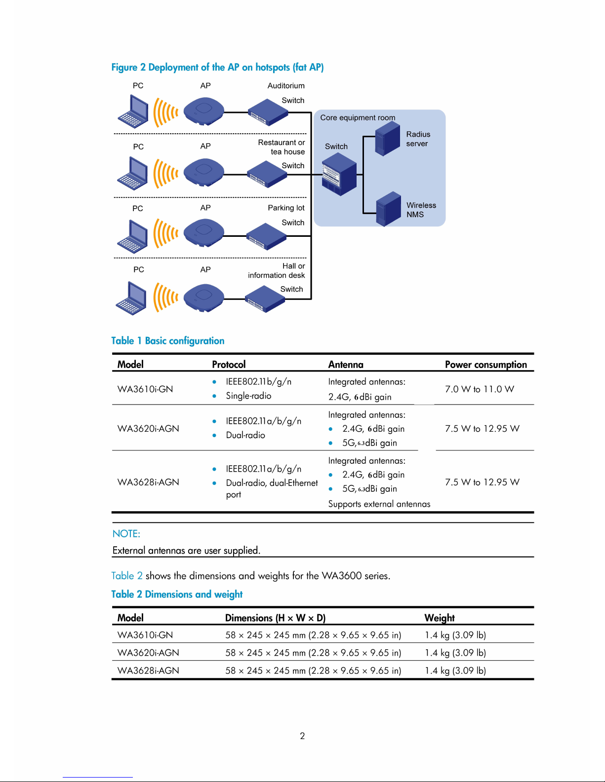
The H3C WA3600 Series Indoor Access Points (referred to as the WA3600 series hereinafter) includes
the WA3610i-GN, WA3620i-AGN, and WA3628i-AGN. All of them have integrated antennas, and the
WA3628i-AGN also supports external antennas. The WA3600 series can serve as fit APs to cooperate
with wireless switches or access controllers to provide wireless access for WLAN users. All configuration
tas ks are c onfigured on the wireless switches or access controllers. The WA 3600 series can also operate
as fat APs to provide wireless access for WLAN users.
Figure 1 Deployment of the AP on hotspots (fit AP)
Page 7
Page 8
3
Preparing for installation
Safety recommendations
W
ARNING!
Only qualified personnel can install and remove a WA3600 series and its accessories. You must read all
safety instructions supplied with the access points before installation and operation.
To avoid possible bodily injury and equipment damage, read the following safety recommendations
before you install a WA3600 series. Note that the recommendations do not cover every possible
hazardous condition.
• Take adequate safety measures to avoid injury and access point damage.
• Make sure that the ground is dry and flat and anti-slip measures are in place.
• Keep the chassis clean and dust-free.
• Do not place the access point in a moist area and avoid liquid surrounding the access point.
• Keep the chassis and installation tools away from walkways.
Examining the installation site
Before installation, examine the installation site to keep the AP under a good operational environment.
You can examine the installation site from the following aspects:
Temperature and humidity requirements
Table 3 Environment specifications
S
p
ecification Range
Operating temperature (indoor)
–10°C to +55°C (14°F to 131°F)
Storage temperature
–40°C to +70°C (–40°F to +158°F)
Operating humidity (noncondensing)
5% to 95%
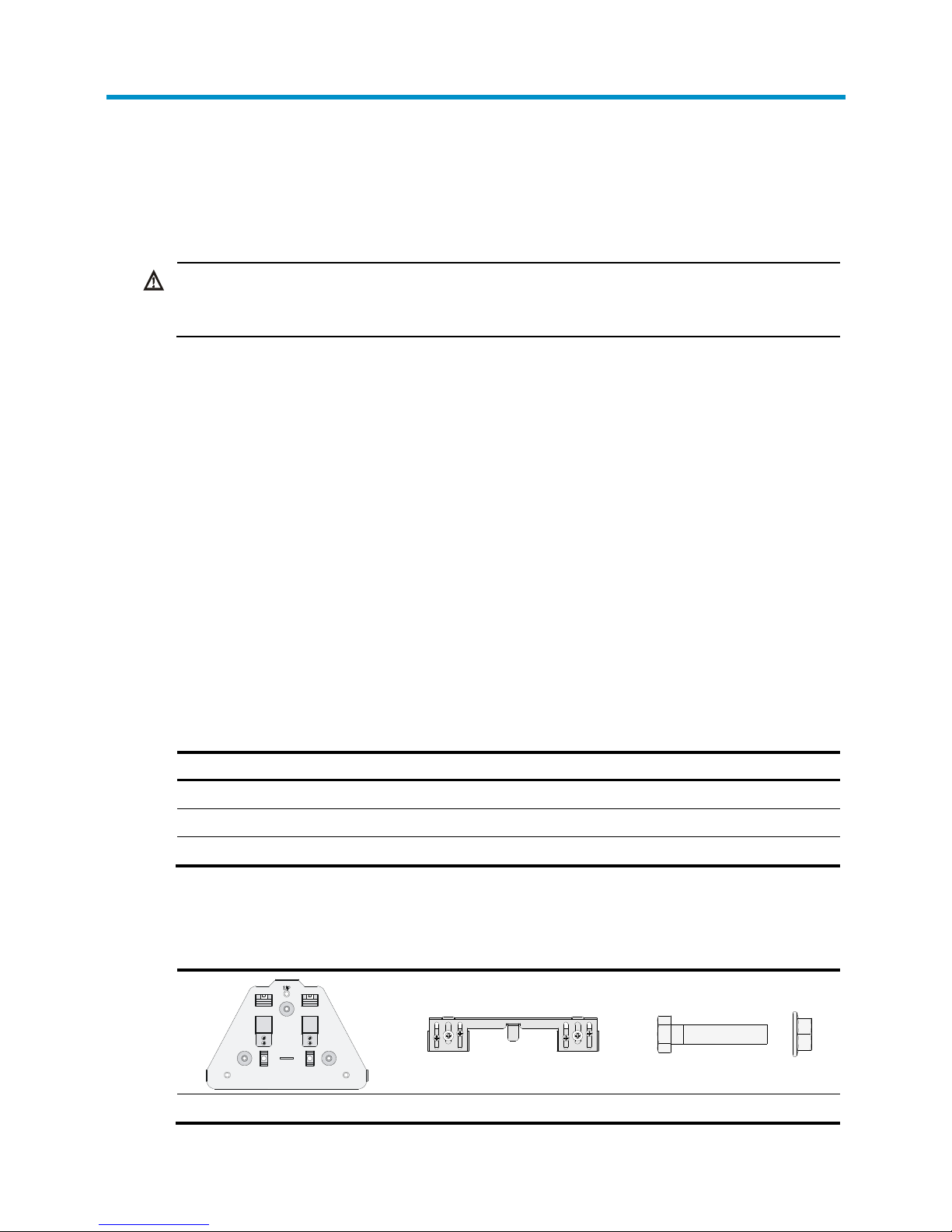
Accessories provided with the AP
The following accessories are provided with the AP:
Wall-mounting bracket T-rail holder Hex-head bolt and nut
Page 9
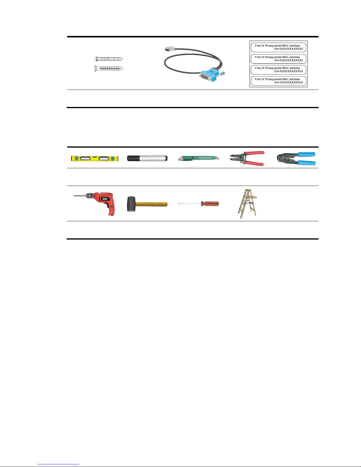
4
Wall anchor kit
Console cable (provided with the fat
AP only)
MAC address label
User-supplied installation tools and equipment
When you install a WA3600 access point, you may need the following tools:
Level Marker Knife Wire stripper
RJ-45 crimping
tool
Percussion drill with
matching drills
Rubber hammer
Phillips
screwdriver
Ladder
Page 10
5
Installing the AP
CAUTION:
The WA3600 series is usually installed on a high position, such as a wall or ceiling, so the maintenance
personnel cannot log in from the console port to maintain and debug the AP. H3C recommends that you
lo
g
in to the AP through the console port to perform remote login (Telnet or web login) configuration, or
log in through Telnet or web by using the default login information before you install the AP. For more
information about logging in to the AP, see “Logging in to the fat AP.”
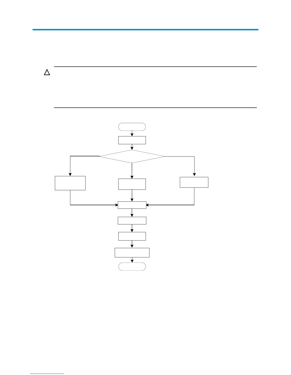
Figure 3 Installation flowchart
Check before installation
Before you install an AP, check the following:
• Connect the power cord and connect the AP to the network. Check the LED status to make sure that
the AP can operate properly. For more information about AP LEDs, see “Appendix LEDs and ports.”
• Check that cabling has been completed.
• The WA3600 series supports 802.3af-compliant PoE. To achieve the best performance, H3C
recommends that you adopt GE connection to the power device.
Wall mounting (II)
Start
Determine the installation position
Wall mounting (I)
Connect the AP to the
network
End
Check before
installation
Install the wall-
mounting bracket
T-rail mounting
Install the wall-
mounting bracket
Attach the T-rail
holder to the T-rail
Install the AP
Connect the
power supply
Secure the AP
Page 11

6
• Record the MAC address and serial number of the AP (marked on the rear of the AP) for future use.
Determining the installation position
Determine the installation position by observing the following principles:
• Leave as few obstacles (such as wall) as possible between APs and clients.
• Install APs away from electronic devices (such as microwave ovens) that may generate radio
frequency (RF) noise.
• Install APs in a place where they will not hinder people’s daily work and life.
• Do not install APs in a place where water seeping, water soaking, and condensing occur. Prevent
water or moisture from entering the APs.
CAUTION:
If part of the power line is routed outdoors, use a power strip with lightning protection (user supplied) to
connect the power cord of the AP to the power line to protect the AP from being damaged by lightning
strikes.
Installing the AP
NOTE:
• The WA3610i-GN, WA3620i-AGN, and WA3628i-AGN are installed in the same way. The followin
g
uses a WA3628i-AGN as an example.
• The WA3600 series can only be used indoors.
Mounting the AP on a wall (I)
To mount the AP on a wall, you need a wall-mounting bracket and wall anchor kit.
Figure 4 Screw hole locations and sizes (in mm)
Page 12
7
CAUTION:
Connect the AP to the network by using an Ethernet cable, and then install the AP to the wall-mounting
bracket when you mount the AP on a wall.
To mount the AP on a wall:
1. Fix the wall-mounting bracket to the wall:
a. Use the wall-mounting bracket as a template to mark the locations of the mounting holes on the
bracket. Drill three 5 mm (0.2 in) diameter holes at the mounting hole locations you marked.
b. Insert a wall anchor into each mounting hole, and tap the wall anchor with a rubber hammer
until it is all flush with the wall surface.
c. Align the holes in the wall-mounting bracket with the anchors and insert screws through the
installation holes into the wall anchors.
d. Adjust the position of the wall-mounting bracket and tighten the screws.
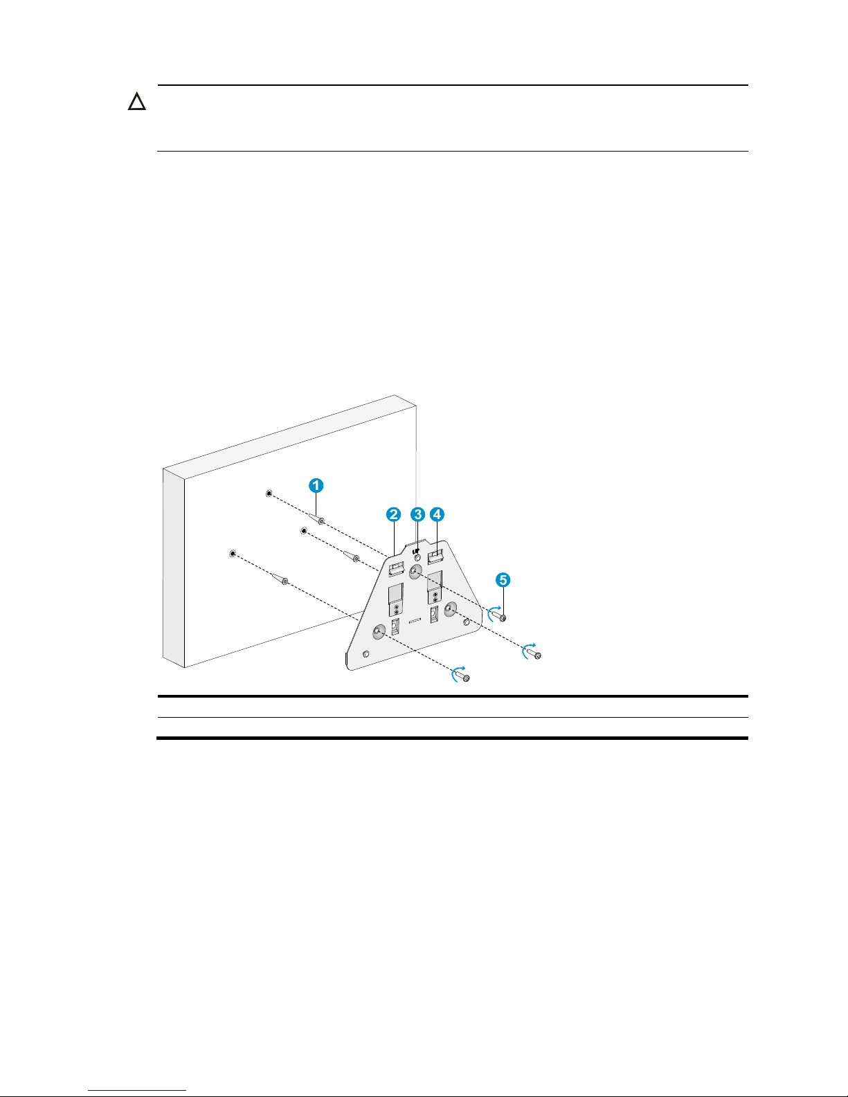
Figure 5 Install the wall-mounting bracket
(1) Wall anchor (2) Wall-mounting bracket
(3) Hook
(4) Clip (5) Screw
2. Connect the AP to the network by using an Ethernet cable.
3. Align the mounting keyhole on the rear of the AP over the hook on the wall-mounting bracket.
See Figure 6.
Page 13

8
Figure 6 Mounting keyholes
(1) Hook (2) Clip
(3) Tab (4) Mounting keyhole
4. Mount the AP on the hook on the wall-mounting bracket. See callout 1 in Figure 7.
5. Pull down the AP with force until it clicks into place. See callout 2 in Figure 7.
Figure 7 Fix the AP onto the wall-mounting bracket
1
2
Page 14

9
Mounting the AP on a wall or ceiling (II)
NOTE:
• The wall or ceiling tiles must be less than 18 mm (0.71 in) thick, and the wall or the ceiling can bear a
weight of at least 5 kg (11.02 lb).
• Do not use this method to mount the AP to a location made of low-intensity materials such as a plaster
ceiling. If this installation method is required in such an environment, put a high-intensity plate beneath
the ceiling to secure the installation.
The two bolt holes shown in Figure 8 are needed for mounting the AP on a wall.
Figure 8 Bolt holes on the wall-mounting bracket (in mm)
(1) Bolt hole 1 (2) Bolt hole 2
To install the AP on a wall:
1. Drill two 6.2 mm (0.24 in) diameter holes in the wall or ceiling where you want to mount the AP.
The distance between the two holes must be the same as the distance between the two bolt holes
on the mounting bracket.
2. Insert the hex-head bolts into the bolt holes on the mounting bracket and the holes in the wall or
ceiling. From the other side of the wall or from above the ceiling, fasten the hex nuts to the
hex-head bolts to fix the mounting bracket to the wall or ceiling.
3. Connect the AP to the network by using an Ethernet cable.
4. Fix the AP to the mounting bracket. For more information, see “Mounting the AP on a wall (I).”
Page 15

10
Figure 9 Mount the AP on a wall
(1) Nut (2) Hex-head bolt
(3) Wall-mounting bracket (4) Hook
CAUTION:
Check that the AP is secured to the mounting bracket to avoid falloff.
Mounting the AP to a T-rail
NOTE:
• The width of the T-rail must be in the range of 14 mm to 24 mm (0.55 in to 0.94 in).
• This installation method applies only to T-rails.
The two 5 mm (0.20 in) diameter holes on the mounting bracket are needed when you mount the AP to
a T-rail. For the wall-mounting bracket appearance, see Figure 4.
Page 16

11
Figure 10 T-rail holder
(1) T-rail clip (2) M4 × 8 screw nut
(3) Clip holder
(4) T-rail holder (5) M3 × 6 screw nut
(6) M4 × 8 screw
(7) M3 × 6 screw (8) Mounting hook
To mount the AP to a ceiling T-rail:
1. Loosen the two M3 × 6 screws on each clip holder just enough (do not remove the screws or they
may get lost).
2. Adjust the T-rail clips to make the T-rail holder wider than the T-rail. See callout 1 in Figure 11. Then
lock the T-rail with the T-rail holder according to the arrow indicated in callout 2 in Figure 11.
Figure 11 Fix the T-rail holder to the T-rail
3. Tighten the four M3 × 6 screws on the two clip holders until the screw heads touch the T-rail, and
then fix the screws.
4. Check whether the T-rail holder is fixed to the T-rail.
5. Hook the mounting clip (see callout 5 in Figure 12) of the wall-mounting bracket to the mounting
hook (see callout 4 in Figure 12) of the
T-rail holder.
6. Insert the two M4 × 8 screws (see callout 1 in Figure 12) through the two 5 mm (0.20 in) diameter
holes on the wall-mounting bracket according to the dashed line shown in Figure 12 and fix the
sc
rews to the T-rail holder.
7. Check whether the wall-mounting bracket is fixed to the T-rail.
8. Connect the AP to the network by using an Ethernet cable.
Page 17

12
9. Install the AP to the wall-mounting bracket. For more information, see “Mounting the AP on a wall
(I).”
Figure 12 Mount the AP
to the T-rail
(1) M4 × 8 screw (2) M3 × 6 screw (3) Hook
(4) Mounting hook
(5) Mounting clip
Securing the AP
NOTE:
The security lock is user supplied.
You can secure the AP by installing a security lock into the security slot on the AP.
To install the security lock:
1. Loop the security cable around a nearby immovable object.
2. Insert the key into the security lock.
3. Insert the security lock latch into the security slot on the access point.
4. Rotate the key right or left to secure the security lock to the access point.
5. Remove the key from the security lock.
Page 18

13
Figure 13 Secure the AP
(1) Security slot (2) Security lock
(3) Security cable
Connecting the power supply
The WA3600 series can be powered by the local power or through 802.3af-compliant PoE. You can
select one as needed.
Check before power-on
Check the following items before you power on the AP:
• The power supply is well grounded when the AP adopts local power supply.
• The PoE power supply is well grounded when the AP adopts PoE power supply.
PoE power supply
If the uplink device of the AP is a PoE switch, use an Ethernet cable to directly connect the Ethernet
interface of the AP to the PoE device.
Page 19

14
Figure 14 PoE connection
(1) Ethernet Port (2) Ethernet Cable
(3) PoE switch
Local power supply
NOTE:
No power adapter and power cable are shipped with the AP.
Table 4 Power adapter specifications
Item Descri
p
tion
Input 100 VAC to 240 VAC
Output
+48V at 0.52 A
The WA3600 series supports both AC and DC power adapters. You can connect the power port of the
AP to the power source through a power adapter to supply power to the AP.
Figure 15 Local power supply connection
(1) Power port
(2) Power adapter
(3) Power source
Page 20

15
Check after power-on
After powering on the AP, check the AP status LED. For more information about AP LEDs, see “Appendix
LEDs and ports.”
Connecting the AP to the network
APs can access the Internet or metropolitan area network (MAN) through the Ethernet uplink interface. To
implement Internet or MAN access, connect the Ethernet port of the AP to an Ethernet port of an Ethernet
switch.
Checking the network connection for the fit AP
When the AP operates as a fit AP, all of its settings are configured on the AC. You can use the display
wlan ap all command to check the AP status on the AC. When the AP status is R/M, the AP has been
successfully connected to the AC (on a WA3628i-AGN for example).
<AC> display wlan ap all
Total Number of APs configured : 1
Total Number of configured APs connected : 1
Total Number of auto APs connected : 0
AP Profiles
State : I = Idle, J = Join, JA = JoinAck, IL = ImageLoad
C = Config, R = Run, KU = KeyUpdate, KC = KeyCfm
--------------------------------------------------------------------------------
AP Name State Model Serial-ID
--------------------------------------------------------------------------------
ap1 R/M WA3628i-AGN 210235A0T6B117000435
-------------------------------------------------------------------------------
Checking the network connection for the fat AP
When the AP operates as a fat AP, use the ping command to ping the uplink network. If the network can
be pinged successfully, the AP is successfully connected to the network.
Page 21

16
Logging in to the fat AP
NOTE:
The WA3600 series is usually installed on a high position. H3C recommends that you lo
g
in to the AP to
configure related settings before you install the AP.
When the WA3600 series operates as a fat AP, you can log in to the AP through the console port, or
through Telnet or web to configure the AP, but you must obtain the IP address of the AP first.
• Logging in through the console port—Logging in through the console port is the most fundamental
login method. To log in through other methods, you must log in through the console port and
perform the required configurations.
• Logging in through Telnet—You can telnet to the device to remotely manage and maintain it.
• Logging in through web—You can log in to the web interface of the device to remotely manage and
maintain it.
Logging in through the console port
Prepare the following before you log in through the console port:
• An 8-core shielded console cable, with a crimped RJ-45 connector at one end, and a DB-9 female
connector at the other end.
• A configuration terminal—A laptop or PC with a serial port.
Setting up the configuration environment
NOTE:
The serial ports on PCs do not support hot swapping. If the AP has been powered on, connect the console
cable to the PC before connecting to the AP, and when you disconnect the cable, first disconnect from the
A
P.
To connect the console cable:
1. Plug the DB-9 female connector to the serial port of the PC.
2. Connect the RJ-45 connector to the console port of the AP.
Page 22

17
Figure 16 Connect the console cable
3. Power on the AP.
The AP’s startup information will be displayed.
Setting terminal parameters
To set terminal parameters, for example, on a Windows XP HyperTerminal:
1. Select Start > All Programs > Accessories > Communications > HyperTerminal.
The Connection Description dialog box appears.
2. Enter the name of the new connection in the Name field and click OK.
Figure 17 Connection description
3. Select the serial port to be used from the Connect using list, and click OK.
Page 23

18
Figure 18 Set the serial port used by the HyperTerminal connection
4. Set Bits per second to 9600, Data bits to 8, Parity to None, Stop bits to 1, and Flow control to None,
and click OK.
Figure 19 Set the serial port parameters
NOTE:
To restore the default settings, click Restore Defaults.
Page 24

19
The HyperTerminal window appears.
Figure 20 HyperTerminal window
Logging in through the console port
Power on the AP, and you can see the following information:
System is starting...
Booting Normal Extend BootWare.
…
System application is starting...
Startup configuration file does not exist.
User interface con0 is available.
Press ENTER to get started.
Logging in through Telnet or web
By default, the Telnet and web functions are enabled. You can use the following default settings to log in
to the web interface:
• Username—admin
• Password—h3capadmin
• Management IP address of VLAN-interface 1 of the AP—192.168.0.50, with the subnet mask
255.255.255.0.
If the default IP address is changed, contact the administrator to get the new IP address, or use the
display vlan 1 command to view the IP address after logging in to the AP from the console port.
NOTE:
For more information about Telnet or web login configuration, see
H3C WA Series Access Points
Configuration Guides
.
Page 25

20
Appendix LEDs and ports
LEDs
Table 5 describes the LEDs provided by the WA3600 series.
Table 5 LED description
Mar
k
Color Status
Description
Green
Flashing at 1 Hz
The AP is booting.
NOTE:
When the AP operates as a fit AP, it is always
in this state before it is registered to an AC.
Breathing A client is connected to the 2.4G port.
Blue
Flashing at 0.25 Hz
The AP has been booted, and is in standby
state (no client is connected to the AP).
NOTE:
When the AP operates as a fit AP, this state
indicates the AP has been registered to an AC.
Flashing at 4 Hz
The AP is updating its system software image
(only available when the AP operates as a fit
AP).
Breathing
A client is connected to the 5G port.
NOTE:
Not available on the WA3610i-GN.
Red
Steady on
An initialization exception has occurred to
the AP.
Flashing at 1 Hz The AP cannot detect any radio interface.
Flashing at 8 Hz
An Ethernet port or radio interface is
operating abnormally.
Alternating
green and blue
Alternating flashing at
1 Hz
Blinking mode.
NOTE:
When the fit AP associated with the AC
receives the blinking command sent by the
AC, it flashes green and blue to show the fit
AP has been associated with the AC.
Breathing green and
blue twice
Clients are connected to both the 2.4G and
5G radio interfaces.
NOTE:
Not available on the WA3610i-GN.
NOTE:
For more information about the blinking mode, see
WX Series Access Controllers Configuration Guides
.
Page 26

21
Ports
The WA3610i-GN and WA3620i-AGN provide the following external ports:
• A console port
• A 10/100/1000 Mbps copper Ethernet port
• A power supply port
The WA3628i-AGN provides the following external ports:
• Three 2.4 GHz antenna ports, and three 5 GHz antenna ports
• A console port
• Two 10/100/1000 Mbps copper Ethernet ports
• A power supply port
NOTE:
The WA3600 series also provides a reset button and a security slot with the dimension of 7 × 3 mm (0.28
× 0.12 in).
Figure 21 Ports on the WA3610i-GN and WA3620i-AGN
(1) Local power port (2) 10/100/1000 Mbps copper Ethernet port
(3) Reset button (4) Console port
(5) Security slot
Table 6 WA3610i-GN and WA3620i-AGN port description
Port Standards and
p
rotocols Description
ETH1
• IEEE802.3
• IEEE802.3u
• IEEE802.3af
10/100/1000 Mbps copper Ethernet port. The
Ethernet port can serve as an uplink interface to
access the Internet or MAN, and as an
802.3af-compliant PoE port at the same time.
DC 48V
• N/A
The local power port is used for +48 VDC power
supply to the device.
Page 27

22
Port Standards and
p
rotocols Description
Console port RS/EIA-232
The console port is used for configuration and
management (for debugging when the AP operates
as a fit AP).
Figure 22 WA3628i-AGN ports
(1) through (3) 5G antenna ports 1/2/3
(4) Local power port
(5) 10/100/1000 Mbps copper Ethernet port 1 (6) 10/100/1000 Mbps copper Ethernet port 2
(7) Reset button (8) Console port
(9) Security slot (10) through (12) 2.4G antenna ports 1/2/3
Table 7 WA3628i-AGN port description
Port Standards and
p
rotocols Description
2.4G-1/2/3
• IEEE802.11b
• IEEE802.11g
• IEEE802.11n
The antenna ports are provided for 2.4 GHz single-RF
antennas
5G-1/2/3
• IEEE802.11a
• IEEE802.11n
The antenna ports are provided for 5 GHz single-RF
antennas
Local power port
• N/A
The local power port is used for +48 VDC power
supply to the device.
ETH1 and ETH2
• IEEE802.3
• IEEE802.3u
• IEEE802.3af
10/100/1000 Mbps copper Ethernet port .The
Ethernet port can serve as an uplink interface to
access the Internet or MAN, and as an
802.3af-compliant PoE port at the same time.
Console port RS/EIA-232
The console port is used for configuration and
management (for debugging when the AP operates
as a fit AP).
1
2
3
4 5 6
7 8 9
10
11
12
Page 28

23
Index
A C D E I L P S U
A
Accessories provided with the AP,3
C
C
heck before installation,5
C
onnecting the AP to the network,15
C
onnecting the power supply,13
D
De
termining the installation position,6
E
Ex
amining the installation site,3
I
Inst
alling the AP,6
L
LEDs
,20
L
ogging in through Telnet or web,19
L
ogging in through the console port,16
P
Po
rts,21
S
S
afety recommendations,3
Sec
uring the AP,12
U
U
ser-supplied installation tools and equipment,4
Page 29

Compliance and Safety Manual
Page 30

i
Contents
Safety Information Sicherheits informationen 安全信息 ································································· 1
Overview Überblick 概述 ············································································································· 1
Conventions Used Symbole Erläuterung der Symbole 应用惯例 ················································ 2
Important Safety Information/Wichtige Sicherheitshinweise/重要安全信息 ································· 3
Electricity Safety Elektrische Sicherheit 用电安全 ······································································ 4
Regulatory Compliance Information ························································································· 5
Regulatory compliance standards ······························································································ 5
European Directives compliance ································································································ 5
Wireless CE Marking ············································································································· 5
EU Country Restriction in 2.4GHz band ·················································································· 7
WEEE Directive–2002/96/EC ·································································································· 7
USA regulatory compliance ········································································································ 8
FCC Part 15 ························································································································· 8
Canada regulatory compliance ································································································· 9
ICES-003······························································································································ 9
RF Compliance ··················································································································· 9
EN55022, AS/NZS CISPR 22, CISPR22 compliance ··········································································· 9
Page 31

ii
List of Tables
Table 1 Safety symbol and description/Sicherheitssymbole und Beschreibung/安全标识和描述 ... 3
Table 2 Regulatory compliance standards .............................................................................................. 5
Table 3 Equipment may be operated in the following country: .......................................................... 5
Page 32

1
Safety Information Sicherheits
informationen 安全信息
Overview Überblick 概述
Warning
Installation and removal of the unit and its accessories must be carried out by qualified
personnel. You must read all of the Safety Instructions supplied with your equipment
before installation and operation.
Warnung
Installation und Ausbau der Anlage und ihrer Zubehö rteile mü ssen von qualifiziertem
Personal realisiert werden. Sie mü ssen vor der Installation oder Bedienung allen
beiliegenden Sicherheitshinweise lesen.
警告
负责安装和日常维护本设备的人员必须具备安全操作基本技能。在操作本设备前,请务必认真阅读
和执行产品手册规定的安全规范。
Note
Before any operation is performed, please read the operation instructions and precautions
carefully to minimize the possibility of accidents. The Note, Caution, Warning and Danger
items in other manuals do not cover all safety precautions that should be followed. They
are only the supplements to the safety precautions for operations as a whole. Therefore,
the personnel in charge of the installation and maintenance of the products are required to
understand these basics of safety operation.
In performing various operations, please follow the local safety regulations. The safety
precautions introduced in the product manuals are supplementary and subject to the local
safety regulations.
When various operations are executed on the products, the precautions and special safety
instructions provided with the products must be followed to the full.
The personnel in charge of the installation and maintenance of the products must be
trained as professionals to master the proper operating methods and all safety
precautions. Only the trained and qualified personnel can perform operations such as
equipment installation and maintenance.
Page 33

2
Anmerkung
Lesen Sie bitte alle Bedienungsanweisungen und Sicherheitvorschriften sorgfältig durch,
bevor Sie das Gerät in Betrieb nehmen. Nur durch Beachtung dieser Hinweise lässt sich das
Unfallrisiko minimieren. Die in anderen Handbü chern aufgefü hrten Anmerkungen,
Achtungen, Warnungen und Gefahren beinhalten nicht alle zu beachtenden
Sicherheitvorschriften. Sie dienen lediglich als Ergänzung. Deshalb muss sich das fü r die
Installation und Instandhaltung der Ausrü stung verantwortliche Personal mit allen
Sicherheitshinweisen vertraut machen.
Bei verschiedenen Bedienungen mü ssen auß erdem die ö rtlichen Sicherheitsvorschriften
beachtet werden. Die in den Handbü chern der einzelnen Produkte aufgefü hrten
Sicherheitshinweise sind Ergänzungen und unterliegen den nationalen
Sicherheitsvorschriften.
Bei verschiedenen Bedienungen mit den Produkten sind deshalb grundsätzlich alle
Sicherheitsvorschriften und spezifischen Sicherheitshinweise genau zu beachten.
Das fü r die Installation und Instandhaltung der Produkte verantwortliche Personal muss
geschult werden, damit sie alle Sicherheitsvorschriften kennen und die Produkten richtig
bedienen zu kö nnen. Nur geschultes und qualifiziertes Personal kann die Installation und
Instandhaltung in korrekter Weise durchfü hren.
说明
为了避免可能发生的事故,请在进行任何操作前,仔细阅读设备操作手册和本章节的安全规范。手
册中 出现的说明、注意、警告、危险,不能涵盖所有的安全预防,仅仅是在整个操作过程中的安全
提示和补充。因此,负责安装和日常维护本设备的人员必须具备安全操作基本技能。
操作人员要按照当地的安全规范进行操作。出现在产品手册中的安全预防措施仅仅是当地安全规范
的补充。
在操作本设备时,请认真执行产品手册规定的安全规范。
设备安装、维护人员必须通过专业培训,并且掌握足够的操作技能和安规预防意识。只有专业人员
才能担任本设备的安装和维护工作。
Conventions Used Symbole Erläuterung der Symbole 应
用惯例
The symbols in this manual are shown in the following table. They are used to remind the
reader of the safety precautions during equipment installation and maintenance.
Die in diesem Handbuch verwendeten Symbole sind in der folgenden Tabelle dargestellt.
Diese Symbole sollen das Personal während der Installation und Instandhaltung der
Ausrüstung an die Wichtigkeit der im Handbuch aufgeführten Sicherheitsvorschriften
erinnern.
以下表格中的安全标识,是用来提示读者在进行设备安装和维护时的安全预防要求。
Page 34

3
Table 1 Safety symbol and description/Sicherheitssymbole und Beschreibung/安全标识和描述
Safety Symbol
Symbole
安全标识
Description
Erläuterung
描述
Generic alarm symbol: To suggest a general safety concern.
Alarm: Hinweis auf ein generelles Sicherheitsproblem.
一般注意标识:用于一般安全提示。
ESD protection symbol: To suggest electrostatic-sensitive equipment.
ESD-Schutz: Hinweis auf ESD-gefährdete Bauteile.
防静电标识:用于表示静电敏感的设备。
Electric shock symbol: To suggest a danger of high voltage.
Elektrischer Schlag: Hinweis auf Gefährdung durch Hochspannung.
电击防护标识:用于表示高压危险。
Important Safety Information/Wichtige
Sicherheitshinweise/重要安全信息
Caution:
You must read all of the installation instructions in the Installation Guide
supplied with your equipment and the following safety instructions before
installation or operation.
Achtung:
Sie müssen vor der Installation oder Bedienung das mit Ihrer Anlage
mitgelieferten Installationshandbuch und die folgende Sicherheitshinweise lesen.
注意:在安装和操作本设备时,务必阅读设备安装手册的内容,以及下文的所有安全说明。
Warning:
Installation and removal of the unit and its accessories must be carried
out by qualified personnel.
Warnung::
Installation und Ausbau der Anlage und ihrer Zubehörteile müssen von
qualifiziertem Personal realisiert werden.
警告: 必须由专业人员来安装和移动设备以及附件。
Warning:
For SELV DC input: the DC power source shall comply with the Safety
Extra-Low Voltage (SELV) requirements of IEC 60950-1.
Warnung:
Mit Gleichstrom betriebenes Modell: Das Gerät arbeitet mit Gleichstrom,
wobei die Anforderungen der Norm (IEC60950-1) für Schutzkleinspannung
eingehalten werden müssen.
警告:SELV DC电源输入:设备使用满足IEC60950-1安规标准的安全超低电压(SELV)电源。
Warning:
Before the power cable is installed or removed, the power must be
turned off.
Warnung:
Das System muss stets abgeschaltet werden, bevor die Zuleitung
angebracht oder entfernt wird.
警告:在安装、移动线缆之前,请切断电源。
Warning:
Before the power cable is connected, it must be confirmed that the
power cord complies with the requirements of the actual installation(see power
cord table.)
Warnung:
Überprüfen Sie vor dem Anbringen der Zuleitung immer, ob das von
Ihnen verwendete Kabel den Anforderungen entspricht(siehe Netzkabel-Tabelle).
Page 35

4
警告: 在进行线缆连接前,请确认线缆和线缆的标识与实际安装要求是一致的(参考电源线
表格)。
Caution:
To ensure the equipment is mounted on the wall firmly, please use a
screw at least 4.2 mm diameter and the screw head at least 8.0 mm diameter.
Achtung:
Um das Gerät an der Wand zu befestigen, benutzen Sie Nagel mit einem
Mindestdurchmesser von 4.2 mm. Der Durchmesser der Nagelkappe muss
mindestens 8.0 mm betragen.
注意:为确保设备紧固的安装在墙上,请用直径最小是4.2mm钉子,并且钉子帽的直径要
大于8.0mm。
Electricity Safety Elektrische Sicherheit 用电安全
Conducting articles, such as a watch, hand chain, bracelet or ring should be removed
during the installation.
Es ist nicht erlaubt während dieser Arbeiten leitende Gegenstände wie Uhren,
Armbänder, Armreifen und Ringe am Körper zu tragen.
在操作中不能穿戴导电性的物品,如:手表,手琏,手镯和项链等。
If water is found in the rack, or the rack is damp, immediately switch off the power
supply.
Sollte sich Wasser im Baugruppenträger befinden oder der Baugruppenträger feucht
sein, ist die Energiezufuhr sofort zu unterbrechen und das System abzuschalten.
如果有液体进入机架或机架有损坏时,立即切断电源。
Page 36

5
Regulatory Compliance Information
Regulatory compliance standards
Table 2 Regulatory compliance standards
Discipline
Standards
EMC
FCC Part 15 (CFR 47) CLASS B
ICES-003 CLASS B
CISPR 22 CLASS B
EN 55022 CLASS B
AS/NZS CISPR22 CLASS B
CISPR 24
EN 55024
EN 61000-3-2
EN 61000-3-3
EN60601-1-2
EN 301 489-1
EN 301 489-17
Safety
UL 60950-1
CAN/CSA C22.2 No 60950-1
IEC 60950-1
EN 60950-1
AS/NZS 60950-1
RF
FCC Bulletin OET-65C
FCC part15 subpart C
RSS-210
RSS-GEN
EN 300 328
EN 50385
European Directives compliance
Wireless CE Marking
Table 3 Equipment may be operated in the following country:
AT
BE
CY
CZ
DK
EE
FI
FR
Page 37

6
AT
BE
CY
CZ
DK
EE
FI
FR
DE
GR
HU
IE
IT
LV
LT
LU
MT
NL
PL
PT
SK
SI
ES
SE
GB
IS
LI
NO
CH
BG
RO
TR
1. Select the country in which the product is installed to ensure product operation is in
compliance with local regulations. For information on how to select the country, refer
to the “H3C A-Series Access Controllers WLAN Command Reference”.
2. Intended use: IEEE 802.11 b/g/n radio LAN device.
3. This product must maintain a minimum body to antenna distance of 20cm.Under these
conditions this product will meet the Basic Restriction limits of 1999/519/EC(Council
Recommendation of 12 July 1999 on the limitation of exposure of the general public to
electromagnetic fields(0Hz-300GHz)).
R&TTE declaration statements:
Česky [Czech]
H3C Company tímto prohlašuje, že tento Zařízení je ve shodě se základními
požadavky a dalšími příslušnými ustanoveními směrnice 1999/5/ES.
Dansk [Danish]
Undertegnede H3C Company erklærer herved, at følgende udstyr zařízení
overholder de væ sentlige krav og øvrige relevante krav i direktiv 1999/5/EF.
Deutsch
[German]
Hiermit erklärt H3C Company, dass sich das Gerät Ausrüstung in
Übereinstimmung mit den grundlegenden Anforderungen und den übrigen
einschlägigen Bestimmungen der Richtlinie 1999/5/EG befindet.
Eesti [Estonian]
Käesolevaga kinnitab H3C Company seadmed vastavust direktiivi 1999/5/EÜ
põhinõuetele ja nimetatud direktiivist tulenevatele teistele asjakohastele
sätetele.
English
Hereby, H3C Company, declares that this Equipment is in compliance with the
essential requirements and other relevant provisions of Directive 1999/5/EC.
Español
[Spanish]
Por medio de la presente H3C Company declara que el equipo cumple con
los requisitos esenciales y cualesquiera otras disposiciones aplicables o
exigibles de la Directiva 1999/5/CE.
Ελληνική
[Greek]
ΜΕ ΣΗΝ ΠΑΡΟΤΑ H3C Company ΔΗΛΩΝΕΙ ΟΣΙ εξοπλισμός ΤΜΜΟΡΥΩΝΕΣΑΙ
ΠΡΟ ΣΙ ΟΤΙΩΔΕΙ ΑΠΑΙΣΗΕΙ ΚΑΙ ΣΙ ΛΟΙΠΕ ΦΕΣΙΚΕ ΔΙΑΣΑΞΕΙ ΣΗ ΟΔΗΓΙΑ
1999/5/ΕΚ.
Français
[French]
Par la présente H3C Company déclare que l'appareil équipement est
conforme aux exigences essentielles et aux autres dispositions pertinentes de la
directive 1999/5/CE.
Italiano [Italian]
Con la presente H3C Company dichiara che questo attrezzatura è conforme
ai requisiti essenziali ed alle altre disposizioni pertinenti stabilite dalla direttiva
1999/5/CE.
Latviski [Latvian]
Ar šo H3C Company deklarē, ka iekārta atbilst Direktīvas 1999/5/EK būtiskajām
prasībām un citiem ar to saistītajiem noteikumiem.
Lietuvių
[Lithuanian]
Šiuo H3C Company deklaruoja, kad šis įranga atitinka esminius reikalavimus ir
kitas 1999/5/EB Direktyvos nuostatas.
Nederlands
[Dutch]
Hierbij verklaart H3C Company dat het toestel uitrusting in overeenstemming is
met de essentiële eisen en de andere relevante bepalingen van richtlijn
1999/5/EG.
Malti [Maltese]
Hawnhekk, H3C Company, jiddikjara li dan tagħmir jikkonforma mal-ħtiġijiet
essenzjali u ma provvedimenti oħrajn relevanti li hemm fid-Dirrettiva 1999/5/EC.
Magyar
Alulírott, H3C Company nyilatkozom, hogy a aprīkojums megfelel a vonatkozó
Page 38

7
[Hungarian]
alapvetõ követelményeknek és az 1999/5/EC irányelv egyéb elõírásainak.
Polski [Polish]
Niniejszym H3C Company oświadcza, że urządzenie jest zgodny z zasadniczymi
wymogami oraz pozostałymi stosownymi postanowieniami Dyrektywy
1999/5/EC.
Português
[Portuguese]
H3C Company declara que este equipamento está conforme com os
requisitos essenciais e outras disposições da Directiva 1999/5/CE.
Slovensko
[Slovenian]
H3C Company izjavlja, da je ta oprema v skladu z bistvenimi zahtevami in
ostalimi relevantnimi določili direktive 1999/5/ES.
Slovensky
[Slovak]
H3C Company týmto vyhlasuje, že zariadenie spĺňa základné požiadavky a
všetky príslušné ustanovenia Smernice 1999/5/ES.
Suomi [Finnish]
H3C Company vakuuttaa täten että laitteet tyyppinen laite on direktiivin
1999/5/EY oleellisten vaatimusten ja sitä koskevien direktiivin muiden ehtojen
mukainen.
Svenska
[Swedish]
Härmed intygar H3C Company att denna utrustning står I överensstämmelse
med de väsentliga egenskapskrav och övriga relevanta bestämmelser som
framgår av direktiv 1999/5/EG.
Íslenska
[Icelandic]
Hér með lýsir H3C Company yfir því að búnaður er í samræ mi við grunnkröfur
og aðrar kröfur, sem gerðar eru í tilskipun 1999/5/EC.
Norsk
[Norwegian]
H3C Company erklæ rer herved at utstyret utstyr er i samsvar med de
grunnleggende krav og øvrige relevante krav i direktiv 1999/5/EF.
The most up to date copy of the signed EU Declaration of Conformity can be downloaded
from:
http://www.h3c.com/portal/Technical_Documents
EU Country Restriction in 2.4GHz band
These products may be used indoors or outdoors in all countries of the European
Community using the 2.4GHz band: Channel 1-13, except where noted below.
1. In Belgium outdoor operation is only permitted using the 2.46-2.4835GHz band:
Channel 13.
2. In France outdoor operation is only permitted using the 2.4-2.454GHz band: Channels
1-7.
3. In Italy the end-user must apply for a license from the national spectrum authority to
operate this device outdoors.
WEEE Directive–2002/96/EC
The products this manual refers to are covered by the Waste Electrical & Electronic
Equipment (WEEE) Directive and must be disposed of in a responsible manner.
Page 39

8
USA regulatory compliance
FCC Part 15
US Federal Communications Commission (FCC) EMC Compliance
This equipment has been tested and found to comply with the limits for a Class B digital
device, pursuant to part 15 of the FCC Rules. These limits are designed to provide
reasonable protection against harmful interference in a residential installation. This
equipment generates uses and can radiate radio frequency energy and, if not installed
and used in accordance with the instructions, may cause harmful interference to radio
communications. However, there is no guarantee that interference will not occur in a
particular installation. If this equipment does cause harmful interference to radio or
television reception, which can be determined by turning the equipment off and on, the
user is encouraged to try to correct the interference by one or more of the following
measures:
Reorient or relocate the receiving antenna.
Increase the separation between the equipment and receiver.
Connect the equipment into an outlet on a circuit different from that to which the
receiver is connected.
Consult the dealer or an experienced radio/ TV technician for help.
These products comply with Part 15 of the FCC Rules. Operation is subject to the following
two conditions:
1. This device may not cause harmful interference.
2. This device must accept any interference received, including interference that may
cause undesired operation.
If the customer modifies the equipment without the authorization of H3C, which directly or
indirectly contribute to the equipment incompliance with FCC requirements for Class B
digital devices, H3C is not liable for such interference problem and the expenses incurred
there from shall be covered by the customers.
RF Requirements
1. RF exposure Hazard Warning
This device generates and radiates radio-frequency energy. To ensure compliance with
the requirements of FCC radio-frequency exposure, a minimum body to antenna distance
of 20cm (8 inch) must be maintained when the device is installed and operated.
2. RF Frequency Requirements
This equipment complies with FCC RF radiation exposure limits set forth for an uncontrolled
environment. This device and its antenna must not be co-located or operating in
conjunction with any other antenna or transmitter.
Antennas
Only use the supplied antenna. Unauthorized antennas, modifications or change to the
antennas could violate FCC regulations and void the user‟s authority to operate the
equipment.
Page 40

9
Canada regulatory compliance
ICES-003
This Class B digital apparatus complies with Canadian Standard ICES-003.
Cet appareil numérique de la classe B est conforme à la norme NMB-003 du Canada.
RF Compliance
This device complies with RSS-210 of Industry Canada.
Operation is subject to the following two conditions: (1) this device may not cause
interference, and (2) this device must accept any interference, including interference that
may cause undesired operation of this device.
L „ utilisation de ce dispositif est autorisée seulement aux conditions suivantes: (1) il ne doit
pas produire de brouillage et (2) l‟ utilisateur du dispositif doit étre prêt à accepter tout
brouillage radioélectrique reçu, même si ce brouillage est susceptible de compromettre le
fonctionnement du dispositif.
The term "IC" before the equipment certification number only signifies that the Industry
Canada technical specifications were met.
To reduce potential radio interference to other users, the antenna type and its gain should
be so chosen that the equivalent isotropically radiated power (EIRP) is not more than that
required for successful communication. To prevent radio interference to the licensed
service, this device is intended to be operated indoors and away from windows to provide
maximum shielding. Equipment (or its transmit antenna) that is installed outdoors is subject
to licensing.
Pour empecher que cet appareil cause du brouillage au service faisant l'objet d'une
licence, il doit etre utilize a l'interieur et devrait etre place loin des fenetres afin de Fournier
un ecram de blindage maximal. Si le matriel (ou son antenne d'emission) est installe a
l'exterieur, il doit faire l'objet d'une licence.
This device must not be co-located or operated in conjunction with any other
unauthorized antenna or transmitter.
EN55022, AS/NZS CISPR 22, CISPR22
compliance
These products comply with the requirements of EN55022,AS/NZS CISPR 22, CISPR22 for
Class B Information Technology Equipment (ITE).
 Loading...