

Page 1

H3C WA Series WLAN Access Points
WLAN Command Reference
Hangzhou H3C Technologies Co., Ltd.
http://www.h3c.com
Document Version: 6W100-20100910
Page 2

Copyright © 2010, Hangzhou H3C Technologies Co., Ltd. and its licensors
All Rights Reserved
No part of this manual may be reproduced or transmitted in any form or by any means without prior
written consent of Hangzhou H3C Technologies Co., Ltd.
Trademarks
Notice
H3C, , Aolynk, , H3Care,
SecPro, SecPoint, SecEngine, SecPath, Comware, Secware, Storware, NQA, VVG, V
, TOP G, , IRF, NetPilot, Neocean, NeoVTL,
2
G, VnG, PSPT,
XGbus, N-Bus, TiGem, InnoVision and HUASAN are trademarks of Hangzhou H3C Technologies Co.,
Ltd.
All other trademarks that may be mentioned in this manual are the property of their respective owners.
The information in this document is subject to change without notice. Every effort has been made in the
preparation of this document to ensure accuracy of the contents, but all statements, information, and
recommendations in this document do not constitute the warranty of any kind, express or implied.
Page 3

Preface
The H3C WA documentation set includes 10 command references, whi ch describe the comma nds and
command syntax options available for the H3C WA series WLAN access points.
The WLAN Command Reference describes WLAN interface, WLAN service, WLAN security, WLAN
RRM, WLAN IDS, WLAN QoS, and WDS configuration commands.
This preface includes:
z Audience
z Conventions
z About the H3C WA Documentation Set
z Obtaining Documentation
z Documentation Feedback
Audience
This documentation is intended for:
z Network planners
z Field technical support and servicing engineers
z Network administrators working with the WA series
Conventions
This section describes the conventions used in this documentation.
Command conventions
Convention Description
Boldface Bold
italic
[ ]
{ x | y | ... }
[ x | y | ... ]
{ x | y | ... } *
[ x | y | ... ] *
text represents commands and keywords that you enter literally as shown.
Italic text represents arguments that you replace with actual values.
Square brackets enclose syntax choices (keywords or arguments) that are
optional.
Braces enclose a set of required syntax choices separated by vertical bars,
from which you select one.
Square brackets enclose a set of optional syntax choices separated by vertical
bars, from which you select one or none.
Asterisk marked braces enclose a set of required syntax choices separated by
vertical bars, from which you select at least one.
Asterisk marked square brackets enclose optional syntax choices separated by
vertical bars, from which you may select multiple choices or none.
&<1-n>
# A line that starts with a pound (#) sign is comments.
The argument or keyword and argument combination before the ampersand (&)
sign can be entered 1 to n times.
Page 4
GUI conventions
Convention Description
Boldface
>
Window names, button names, field names, and menu items are in Boldface.
For example, the
Multi-level menus are separated by angle brackets. For example,
Folder
>
.
New User
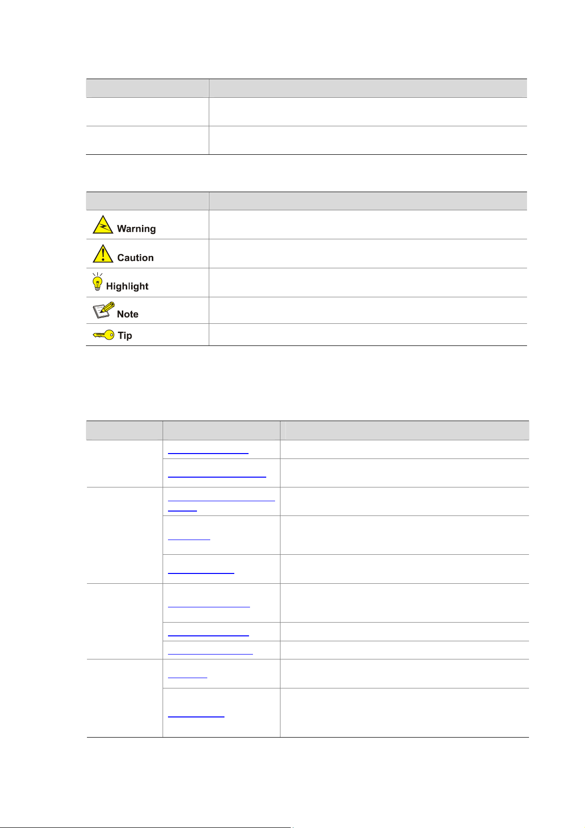
Symbols
Convention Description
Means reader be extremely careful. Improper operation may cause bodily
injury.
Means reader be careful. Improper operation may cause data loss or damage to
equipment.
Means an action or information that needs special attention to ensure
successful configuration or good performance.
Means a complementary description.
Means techniques helpful for you to make configuration with ease.
About the H3C WA Documentation Set
window appears; click OK.
File
>
Create
The H3C WA documentation set includes:
Category Documents Purposes
Product
description and
specifications
Hardware
specifications
and installation
Software
configuration
Operations and
maintenance
Marketing brochures Describe product specifications and benefits.
Technology white papers
Compliance and safety
manual
Quick start
Installation guide
Getting started guide
Configuration guides Describe software features and configuration procedures.
Command references Provide a quick reference to all available commands.
User FAQ
Release notes
Provide an in-depth description of software features and
technologies.
Provides regulatory information and the safety instructions
that must be followed during installation.
Guides you through initial installation and setup procedures to
help you quickly set up and use your AP with the minimum
configuration.
Guides you through hardware specifications and installation
methods to help you install your AP.
Guides you through the main functions of your AP, and
describes how to install and log in to your AP, perform basic
configurations, maintain software, and troubleshoot your AP.
Provides answers to some of the most frequently asked
questions on how to troubleshoot your AP.
Provide information about the product release, including the
version history, hardware and software compatibility matrix,
version upgrade information, technical support information,
and software upgrading.
Page 5

Obtaining Documentation
You can access the most up-to-date H3C product documentation on the World Wide Web at
http://www.h3c.com.
Click the links on the top navigation bar to obtain different categories of product documentation:
[Technical Support & Documents > Technical Documents] – Provides hardware installation, software
upgrading, getting started, and software feature configuration and maintenance documentation.
[Products & Solutions] – Provides information about products and technologies, as well as solutions.
[Technical Support & Documents > Software Download] – Provides the documentation released with
the software version.
Documentation Feedback
You can e-mail your comments about product documentation to info@h3c.com.
We appreciate your comments.
Page 6

Table of Contents
1 Applicable Models and Software Versions·····························································································1-1
2 Feature Matrix············································································································································2-1
3 Command/Parameter Matrix·····················································································································3-1
4 WLAN Interface Configuration Commands·····························································································4-1
WLAN Interface Configuration Commands·····························································································4-1
description·······································································································································4-1
display interface wlan-bss ···············································································································4-2
display interface wlan-mesh············································································································4-3
display interface wlan-radio·············································································································4-4
interface wlan-bss····························································································································4-6
interface wlan-mesh ························································································································4-7
interface wlan-radio·························································································································4-7
shutdown (WLAN-Radio interface view)··························································································4-8
shutdown (WLAN-BSS interface view)····························································································4-8
5 WLAN Security Configuration Commands·····························································································5-1
authentication-method·····················································································································5-1
cipher-suite······································································································································5-2
gtk-rekey client-offline enable··········································································································5-2
gtk-rekey enable······························································································································5-3
gtk-rekey method·····························································································································5-4
ptk-lifetime·······································································································································5-5
security-ie········································································································································5-5
tkip-cm-time·····································································································································5-6
wep default-key ·······························································································································5-6
wep key-id ·······································································································································5-7
wep mode········································································································································5-8
6 WLAN RRM Configuration Commands ···································································································6-1
autochannel-set avoid-dot11h·········································································································6-1
display wlan rrm·······························································································································6-1
dot11a··············································································································································6-3
dot11b··············································································································································6-4
dot11g··············································································································································6-4
dot11g protection enable·················································································································6-5
dot11n mandatory maximum-mcs···································································································6-6
dot11n support maximum-mcs········································································································6-7
power-constraint······························································································································6-7
spectrum-management enable········································································································6-8
wlan rrm···········································································································································6-8
i
Page 7

7 WLAN IDS Configuration Commands······································································································7-1
WLAN Rouge AP Configuration Commands··························································································7-1
attack-detection enable ···················································································································7-1
display wlan ids history····················································································································7-2
display wlan ids statistics·················································································································7-3
wlan ids············································································································································7-4
reset wlan ids history·······················································································································7-5
reset wlan ids statistics····················································································································7-5
WLAN Frame Filtering Configuration Commands ··················································································7-6
display wlan blacklist·······················································································································7-6
display wlan whitelist·······················································································································7-7
dynamic-blacklist enable ·················································································································7-8
dynamic-blacklist lifetime·················································································································7-8
reset wlan dynamic-blacklist············································································································7-9
static-blacklist mac-address ············································································································7-9
whitelist mac-address····················································································································7-10
8 WLAN QoS Configuration Commands····································································································8-1
display wlan wmm ···························································································································8-1
reset wlan wmm·······························································································································8-6
wmm cac policy·······························································································································8-7
wmm edca radio······························································································································8-8
wmm edca client (ac-vo and ac-vi)··································································································8-9
wmm edca client (ac-be and ac-bk) ······························································································8-10
wmm enable··································································································································8-11
wmm svp map-ac ··························································································································8-12
9 WDS Configuration Commands···············································································································9-1
bind wlan-mesh ·······························································································································9-1
display wlan mesh-link·····················································································································9-1
display wlan mesh-profile················································································································9-2
display wlan mp-policy·····················································································································9-3
link-hold-rssi ····································································································································9-4
link-initiation enable·························································································································9-5
link-keep-alive··································································································································9-6
link-maximum-number·····················································································································9-6
link rate-mode··································································································································9-7
link-saturation-rssi ···························································································································9-7
mesh-id············································································································································9-8
mesh-profile·····································································································································9-8
mesh-profile enable·························································································································9-9
mesh peer-mac-address··················································································································9-9
mp-policy·······································································································································9-10
probe-request-interval ···················································································································9-11
wlan mesh-profile ··························································································································9-11
wlan mp-policy·······························································································································9-12
wlan uplink-interface mesh-link·····································································································9-12
ii
Page 8

10 WLAN Service Configuration Commands···························································································10-1
a-mpdu enable·······························································································································10-1
a-msdu enable·······························································································································10-2
beacon ssid-hide ···························································································································10-2
beacon-interval······························································································································10-3
channel··········································································································································10-3
channel band-width ·······················································································································10-4
client dot11n-only ··························································································································10-5
client max-count ····························································································································10-5
display wlan client··························································································································10-6
display wlan service-template ·······································································································10-9
display wlan statistics··················································································································10-10
dtim··············································································································································10-12
fragment-threshold ······················································································································10-13
long-retry threshold······················································································································10-13
max-power···································································································································10-14
max-rx-duration ···························································································································10-14
preamble······································································································································10-15
radio-type·····································································································································10-16
reset wlan client···························································································································10-16
reset wlan statistics ·····················································································································10-17
rts-threshold·································································································································10-17
service-template (WLAN radio interface view)············································································10-18
service-template { disable | enable } (WLAN service template view)··········································10-18
short-gi enable·····························································································································10-19
short-retry threshold ····················································································································10-20
shutdown ·····································································································································10-20
ssid ··············································································································································10-21
wlan broadcast-probe reply·········································································································10-21
wlan client idle-timeout················································································································10-22
wlan client keep-alive ··················································································································10-22
wlan country-code ·······················································································································10-23
wlan service-template··················································································································10-26
wlan uplink-interface····················································································································10-26
11 Wireless User Isolation·························································································································11-1
l2fw wlan-client-isolation enable····································································································11-1
12 Index ·······················································································································································12-1
iii
Page 9

z The models listed in this document are not applicable to all regions. Please consult your local sales
office for the models applicable to your region.
z Read this chapter before using an H3C WA series WLAN access point.
1 Applicable Models and Software Versions
H3C WA series WLAN access points include the WA2200 series and WA2600 series. Table 1-1 shows
the applicable models and software versions.
Table 1-1 Applicable models and software versions
Series Model Software version
WA2200 series
WA2600 series
WA2200 series access
points (indoors)
WA2200 series access
points (outdoors)
WA2600 series access
points (indoors)
WA2600 series access
points (enhanced)
WA2210-AG
WA2220-AG
WA2210X-G
WA2220X-AG
WA2610-AGN
WA2612-AGN
WA2620-AGN
WA2610E-AGN
WA2620E-AGN
R 1115
R 1106
R 1109
1-1
Page 10

2 Feature Matrix
z Support of the H3C WA series WLAN access points for features, commands and parameters may
vary by device model. See this document for more information.
z For information about feature support, see Table 2-1. For information about command and
parameter support, see
z The term AP in this document refers to common APs, wireless bridges, or mesh APs.
Table 2-1 Feature matrix
Document Feature WA2200 series WA2600 series
Table 3-1.
Fundamentals
Configuration Guide
WLAN Configuration
Guide
Layer 2 – LAN
Switching
Configuration Guide
Layer 3 – IP Services
Configuration Guide
IP Multicast
Configuration Guide
Security Configuration
Guide
HTTPS Not supported Supported
802.11n radio mode Not supported Supported
802.11n bandwidth mode Not supported Supported
802.11n rate configuration Not supported Supported
Supported on
Optical Ethernet interface
GE interface Not supported Supported
DHCP server configuration Not supported Supported
DHCPv6 configuration Not supported Supported
IGMP snooping configuration Not supported Supported
MLD snooping configuration Not supported Supported
SSH2.0 Not supported Supported
WA2210X-G/WA2220XAG only
Not supported
2-1
Page 11

3 Command/Parameter Matrix
Table 3-1 Command/Parameter matrix
Document Module Command/Parameter WA2200 series WA2600 series
Fundamentals
Command
Reference
WLAN
Command
Reference
HTTP commands
WLAN service
commands
display ip https
ip https acl
ip https certificate
access-control-policy
ip https enable
a-mpdu enable
a-msdu enable
channel band-width
client dot11n-only
preamble
radio-type
short-gi enable
dot11a { disabled-rate |
mandatory-rate |
supported-rate
{
long
short }
|
} rate-value
Not supported Supported
Not supported Supported
Not supported Supported
Not supported Supported
Not supported Supported
Not supported Supported
Not supported Supported
Not supported Supported
Only APs that
support the
802.11b/g radio
mode support this
command.
Keywords
dot11an
dot11gn
supported
Not supported Supported
Only APs that
support 802.11a
radio mode
support this
command.
and
not
Only APs that
support the
802.11b/g radio
mode support this
command.
Supported
Only APs that
support 802.11a
radio mode
support this
command.
WLAN RRM
commands
dot11n mandatory
maximum-mcs
dot11n support
maximum-mcs
power-constraint
power-constraint
3-1
Not supported Supported
Not supported Supported
Only APs that
support the
802.11a radio
mode support this
command.
Only APs that
support the
802.11a radio
mode support this
command.
Page 12

Document Module Command/Parameter WA2200 series WA2600 series
The maximum
number of
broadcast packets
that can be
forwarded on an
Ethernet interface
per second
broadcast-suppression
pps
{ ratio |
max-pps }
pps
ranges from 1 to
148810.
max-pps
pps
max-pps
ranges from 1 to
1488100.
Layer 2 – LAN
Switching
Command
Reference
Layer 3 - IP
Services
Command
Reference
The maximum
number of multicast
packets allowed on
an Ethernet
interface per
second
The maximum
number of unknown
unicast packets
allowed on an
Ethernet interface
per second
DHCP commands
DHCPv6
commands
multicast-suppression
{ ratio |
unicast-suppression
|
DHCP server configuration
commands
display ipv6 dhcp client
[
interface-number ]
display ipv6 dhcp client
statistics [ interface
interface-type
interface-number ]
display ipv6 dhcp duid
reset ipv6 dhcp client
statistics [ interface
interface-type
interface-number ]
pps
pps
max-pps }
interface
max-pps }
interface-type
{ ratio
Not supported Supported
pps
max-pps
ranges from 1 to
148810.
pps
max-pps
ranges from 1 to
148810.
Not supported Supported
Not supported Supported
Not supported Supported
Not supported Supported
pps
max-pps
ranges from 1 to
1488100.
pps
max-pps
ranges from 1 to
1488100.
3-2
Page 13

z The models listed in this document are not applicable to all regions. Please consult your local sales
office for the models applicable to your region.
z Support of the H3C WA series WLAN access points (APs) for commands may vary by AP model.
For more information, see Feature Matrix.
z The interface types and the number of interfaces vary by AP model.
4 WLAN Interface Configuration Commands
WLAN Interface Configuration Commands
description
Syntax
description text
undo description
View
WLAN-BSS interface view, WLAN-Radio interface view, WLAN mesh interface view
Default Level
2: System level
Parameters
text: Description of an interface, a string of 1 to 80 characters. Currently, the AP supports the following
types of characters or symbols: standard English characters (numbers and case-sensitive letters),
special English characters, spaces, and other characters or symbols that conform to the Unicode
standard.
4-1
Page 14

z An interface description can be the mixture of English characters and other Unicode characters.
z To use a type of Unicode characters or symbols in an interface description, install the
z Each Unicode character or symbol (non-English characters) takes the space of two regular
Description
Use the description command to set the description of the current interface.
Use the undo description command to restore the default.
The mixed description cannot exceed the specified length.
corresponding Input Method Editor (IME) and log in to the AP through remote login software that
supports this character type.
characters. When the length of a description string reaches or exceeds the maximum line width on
the terminal software, the software starts a new line, possibly breaking a Unicode character into
two parts. As a result, garbled characters may be displayed at the end of a line.
By default, the description of an interface is interface-name + interface.
Examples
# Set the description of WLAN-Radio 1/0/1 to WLAN-Radio1.
<Sysname> system-view
[Sysname] interface wlan-radio 1/0/1
[Sysname-WLAN-Radio1/0/1] description WLAN-Radio1
display interface wlan-bss
Syntax
display interface wlan-bss [ interface-number ]
View
Any view
Default Level
1: Monitor level
Parameters
interface-number: Specifies an existing WLAN-BSS interface by its interface number.
Description
Use the display interface wlan-bss command to display information about the specified WLAN-BSS
interface or all WLAN-BSS interfaces.
Examples
# Display information about WLAN-BSS 1.
<Sysname> display interface wlan-bss 1
WLAN-BSS1 current state: DOWN
IP Packet Frame Type: PKTFMT_ETHNT_2, Hardware Address: 000f-e2c0-0110
Description: WLAN-BSS1 Interface
4-2
Page 15

PVID: 1
Port link-type: access
Tagged VLAN ID : none
Untagged VLAN ID : 1
Port priority: 0
Maximum client number: 64
Clients: 0 associating, 0 associated
Input (total) : 0 packets, 0 bytes
: 0 unicasts, 0 bytes
: 0 broadcasts, 0 bytes
Output (total): 0 packets, 0 bytes
: 0 unicasts, 0 bytes
: 0 broadcasts, 0 bytes
Table 4-1 display interface wlan-bss command output description
Field Description
WLAN-BSS1 current state Physical-layer link state of the interface
IP Packet Frame Type Encapsulation type of the frames that the interface sends out
Hardware Address MAC address of the frames that the interface sends out
Description Description of the interface
PVID Default VLAN ID of the interface
Port link-type Link type of the interface, which can only be access currently.
Tagged VLAN ID VLANs whose packets are sent by the interface with the VLAN tag.
Untagged VLAN ID
VLANs whose packets are sent by the interface with the VLAN tag
removed.
Port priority Priority of the interface.
Maximum client number Maximum number of clients allowed to access the interface.
Clients: 0 associating, 0 associated
Clients: the number of associating clients, and the number of
associated clients.
Statistics on packets received at the physical layer:
Input (total) : 0 packets, 0 bytes
: 0 unicasts, 0 bytes
: 0 broadcasts, 0 bytes
z The total number of packets, and the total number of bytes.
z The total number of unicast packets, and the total number of
unicast bytes.
z The total number of broadcast packets, and the total number of
broadcast bytes.
Statistics on packets sent at the physical layer:
Output (total): 0 packets, 0 bytes
: 0 unicasts, 0 bytes
: 0 broadcasts, 0 bytes
z The total number of packets, and the total number of bytes.
z The total number of unicast packets, and the total number of
unicast bytes.
z The total number of broadcast packets, and the total number of
broadcast bytes.
display interface wlan-mesh
Syntax
display interface wlan-mesh [ interface-number ]
4-3
Page 16

View
Any view
Default Level
1. Monitor level
Parameters
interface-number: Specifies a WLAN mesh interface by its interface number. The specified interface
must be one already created.
Description
Use the display interface wlan-mesh command to display information about the specified WLAN
mesh interface or all WLAN mesh interfaces already created if no interface is specified.
Examples
# Display information about WLAN mesh interface 3.
<Sysname> display interface wlan-mesh 3
WLAN-MESH3 current state: DOWN
IP Packet Frame Type: PKTFMT_ETHNT_2, Hardware Address: 000f-e2c0-0110
Description: WLAN-MESH3 Interface
PVID: 1
Port link-type: access
Tagged VLAN ID : none
Untagged VLAN ID : 1
For more details about the fields in the above output, see Table 4-1.
display interface wlan-radio
Syntax
display interface wlan-radio [ interface-number ]
View
Any view
Default Level
1: Monitor level
Parameters
interface-number: Displays information about the WLAN-Radio interface specifie d by interface-number,
which is an interface number .
Description
Use the display interface wlan-radio command to display information about the specified
WLAN-Radio interface or all WLAN-Radio interfaces.
Examples
# Display information about WLAN-Radio 1/0/1.
<Sysname> display interface wlan-radio 1/0/1
WLAN-Radio1/0/1 current state: UP
IP Packet Frame Type: PKTFMT_IEEE_802.11, Hardware Address: 000f-e2c0-0110
Description: WLAN-Radio1/0/1 Interface
4-4
Page 17

Radio-type 11a, channel auto(157), power(dBm) 19 auto (4)
Received: 0 authentication frames, 0 association frames
Sent out: 0 authentication frames, 0 association frames
Stations: 0 associating, 0 associated
Input : 30007 packets, 1536614 bytes
: 13565 unicasts, 520774 bytes
: 16442 broadcasts, 1015840 bytes
: 0 fragmented
: 5687 discarded, 263913 bytes
: 0 duplicates, 3054 FCS errors
: 2 decryption errors
Output: 10002 packets, 1154819 bytes
: 10002 unicasts, 1154819 bytes
: 0 broadcasts, 0 bytes
: 0 fragmented
: 1686 discarded, 195145 bytes
: 0 failed RTS, 2813 failed ACK
: 8570 transmit retries, 2200 multiple transmit retries
Table 4-2 display interface wlan-radio command output description
Field Description
WLAN-Radio1/1 current state Physical-layer link state of the WLAN-Radio interface
IP Packet Frame Type Encapsulation type of the frames that the interface sends out
Hardware Address MAC address of the frames that the interface sends out
Description Description of the interface
Radio-type 11a Radio type of the interface
Channel used by the interface. The keyword
auto
means the
channel is automatically selected and 157 is the number of the
selected channel.
channel auto(157)
If the channel is manually selected, the field will be displayed in
the format of
channel
configured-channel.
Available channels depend on the country code and radio type.
Transmit power of the interface (in dBm). The value 19 is the
transmit power configured by the user; auto indicates that the
actual power is different from that configured by the user; the
bracketed number, is the current transmission power, 4 dBm in
this sample output. (If spectrum management and power
constraint have been configured for the 802.11a bands, the
actual transmit power on the interface may be different from the
power(dBm) 19 auto (4)
configured value, depending on the configuration of two
commands:
max-power
information about the
power-constraint
command, see WLAN Service and WLAN
power-constraint
and
max-power
.) For more
command and the
RRM in the WLAN Command Reference.
If the protocol being used is not 802.11a or the power constraint
function on the 802.11a frequencies is not configured even
though 802.11a is used, this field will be displayed as
power(dBm) configured-power.
Received: 0 authentication frames, 0
association frames
Sent out: 0 authentication frames, 0
association frames
The number of received authentication frames, and the number
of received association frames.
The number of sent authentication frames, and the number of
sent association frames.
4-5
Page 18

Field Description
Stations: 0 associating, 0 associated
Input : 5620 packets, 254801 bytes
: 0 unicasts, 0 bytes
: 5620 broadcasts, 254801 bytes
: 0 fragmented
: 0 discarded, 0 bytes
: 0 duplicates, 96 FCS errors
: 0 decryption errors
Output: 0 packets, 0 bytes
: 0 unicasts, 0 bytes
: 0 broadcasts, 0 bytes
: 0 fragmented
: 0 discarded, 0 bytes
: 0 failed RTS, 0 failed ACK
: 0 transmit retries, 0 multiple transmit
retries
The number of associating stations, and the number of
associated stations.
Statistics on packets received at the physical layer:
z The total number of packets, and the total number of bytes.
z The total number of unicast packets, and the total number of
unicast bytes.
z The total number of broadcast packets, and the total number
of broadcast bytes.
z The number of fragmented packets.
z The number of dropped packets, and the number of dropped
bytes.
z The number of received duplicate frames, and the number of
FCS errors.
z The number of decryption errors.
Statistics on packets sent at the physical layer:
z The total number of packets, and the total number of bytes.
z The total number of unicast packets, and the total number of
unicast bytes.
z The total number of broadcast packets, and the total number
of broadcast bytes.
z The number of fragmented packets.
z The number of dropped packets, and the number of dropped
bytes.
z The number of RTS packets failing to be sent, and the
number of ACK packets failing to be sent.
z The number of retransmitted frames, and the number of
transmit retries.
interface wlan-bss
Syntax
interface wlan-bss interface-number
undo interface wlan-bss interface-number
View
System view
Default Level
2: System level
Parameters
interface-number: WLAN-BSS interface number, which ranges from 0 to 255.
Description
Use the interface wlan-bss command to enter WLAN-BSS interface view. If the WLAN-BSS interface
identified by the interface-number argument does not exist, this command creates the WLAN-BSS
interface first.
Use the undo interface wlan-bss command to remove a WLAN-BSS interface.
Examples
# Create WLAN-BSS interface 1.
4-6
Page 19

<Sysname> system-view
[Sysname] interface wlan-bss 1
[Sysname-WLAN-BSS1]
interface wlan-mesh
Syntax
interface wlan-mesh interface-number
undo interface wlan-mesh interface-number
View
System view
Default Level
2. System level
Parameters
interface-number: Number of a WLAN mesh interface. The value range for this argument is 1 to 32.
Description
Use the interface wlan-mesh command to enter WLAN mesh interface view. If the specified WLAN
mesh interface does not exist, the command creates the WLAN mesh interface first.
Use the undo interface wlan-mesh command to delete the specified WLAN mesh interface.
Examples
# Create WLAN mesh interface 2 in system view.
<Sysname> system-view
[Sysname] interface wlan-mesh 2
[Sysname-WLAN-MESH2]
interface wlan-radio
Syntax
interface wlan-radio interface-number
View
System view
Default Level
2: System level
Parameters
interface-number: WLAN-Radio interface number.
Description
Use the interface wlan-radio command to enter WLAN-Radio interface view.
Examples
# Enter WLAN-Radio 1/0/1 interface view.
<Sysname> system-view
[Sysname] interface wlan-radio 1/0/1
[Sysname-WLAN-Radio1/0/1]
4-7
Page 20

shutdown (WLAN-Radio interface view)
Syntax
shutdown
undo shutdown
View
WLAN-Radio interface view
Default Level
2: System level
Parameters
None
Description
Use the shutdown command to shut down the current WLAN-Ra dio interfa ce.
Use the undo shutdown command to bring up the current WLA N-Radio interface.
By default, a WLAN-Radio interface is up.
Examples
# Shut down the interface WLAN-Radio 1/0/1.
<Sysname>system-view
[Sysname] interface wlan-radio 1/0/1
[Sysname-WLAN-Radio1/0/1] shutdown
shutdown (WLAN-BSS interface view)
Syntax
shutdown
undo shutdown
View
WLAN-BSS interface view
Default Level
2: System level
Parameters
None
Description
Use the shutdown command to shut down the current WLAN-BSS interface.
Use the undo shutdown command to bring up the current WLAN-BSS interface.
By default, a WLAN-BSS interface is up.
After a WLAN-BSS interface is shut down, the connection between the interface and the wireless
device will be torn down.
Examples
# Shut down the interface WLAN-BSS 1.
4-8
Page 21

<Sysname>system-view
[Sysname] interface wlan-bss 1
[Sysname-WLAN-BSS1] shutdown
4-9
Page 22

z The models listed in this document are not applicable to all regions. Please consult your local sales
office for the models applicable to your region.
z Support of the H3C WA series WLAN access points (APs) for commands may vary by AP model.
For more information, see Feature Matrix.
z The interface types and the number of interfaces vary by AP model.
5 WLAN Security Configuration Commands
authentication-method
Syntax
authentication-method { open-system | shared-key }
undo authentication-method { open-system | shared-key }
View
WLAN service template view
Default Level
2: System level
Parameters
open-system: Enables open system authentication.
shared-key: Enables shared key authentication.
Description
Use the authentication-method command to select 802.11 authentication method to be used.
Use the undo authentication-method command to disable the selected authentication method.
By default, open system authentication is enabled.
When you use this command to set the authentication method, if the current service template is of
crypto type, and the encryption mode is WEP, you can set the authentication method to either open
system or shared key.
z If the current service template is of clear type, you can only enable open system authentication.
z If the current service template is of crypto type, you can enable open system or shared key
authentication.
5-1
Page 23

Examples
# Enable the open system authentication.
<Sysname> system-view
[Sysname] wlan service-template 1 clear
[Sysname-wlan-st-1] authentication-method open-system
# Enable shared key authentication.
<Sysname> system-view
[Sysname] wlan service-template 1 crypto
[Sysname-wlan-st-1] authentication-method shared-key
cipher-suite
Syntax
cipher-suite { ccmp | tkip | wep40 | wep104 | wep128}*
undo cipher-suite { ccmp | tkip | wep40 | wep104 | wep128}*
View
WLAN service template view (crypto type)
Default Level
2: System level
Parameters
ccmp: Enables the CCMP cipher suite. CCMP is an AES-based encryption method.
tkip: Enables the TKIP cipher suite. TKIP is an encryption method based on RC4 and dynamic key
management.
wep40: Enabl es the WEP-40 cipher suite. WEP is an encryption method based on RC4 and shared key
management.
wep104: Enables the WEP-104 cipher suite.
wep128: Enables the WEP-128 cipher suite.
Description
Use cipher-suite command to select the cipher suite used in the encryption of frames. The cipher
suites supported are CCMP, TKIP, WEP40, WEP104 and WEP128.
Use the undo cipher-suite command to disable the selected cipher suite.
By default, no cipher suite is selected.
Examples
# Enable TKIP cipher suite.
<Sysname> system-view
[Sysname] wlan service-template 1 crypto
[Sysname-wlan-st-1] cipher-suite tkip
gtk-rekey client-offline enable
Syntax
gtk-rekey client-offline enable
undo gtk-rekey client-offline
5-2
Page 24

View
WLAN service template view (crypto type)
Default Level
2: System level
Parameters
None
Description
Use the gtk-rekey client-offline enable to enable refreshing group temporal key (GTK) when some
client is off-line. This function is effective when the gtk-rekey enable command is executed.
Use the undo gtk-rekey client-offline command to set not refreshing GTK when some client is off-line.
By default, GTK is not refreshed when some client is off-line.
Examples
# Enable GTK refreshing when some client is off-line.
<Sysname> system-view
[Sysname] wlan service-template 1 crypto
[Sysname-wlan-st-1] gtk-rekey client-offline enable
gtk-rekey enable
Syntax
gtk-rekey enable
undo gtk-rekey enable
View
WLAN service template view (crypto type)
Default Level
2: System level
Parameters
None
Description
Use the gtk-rekey enable command to allow GTK refresh.
Use undo gtk-rekey enable command to disable GTK refresh.
By default, GTK refresh is enabled.
Examples
# Disable GTK refresh.
<Sysname> system-view
[Sysname] wlan service-template 1 crypto
[Sysname-wlan-st-1] undo gtk-rekey enable
5-3
Page 25

gtk-rekey method
Syntax
gtk-rekey method { packet-based [ packet ] | time-based [ time ] }
undo gtk-rekey method
View
WLAN service template view (crypto type)
Default Level
2: System level
Parameters
packet-based: Indicates GTK will be rekeyed after transmitting a specified number of packets.
packet: Number of packets (including multicasts and broadcast s) that are transmitted before the GTK is
refreshed. The value ranges from 5000 to 4294967295.
time-based: Indicates GTK will be rekeyed on time based.
time: Specifies the time after which the GTK is refreshed. The value ranges from 180 to 604800
seconds.
Description
Use the gtk-rekey method command to select a mechanism for re-keying GTK.
Use the undo gtk-rekey method command to set the refreshing method to the default value.
By default, the GTK refreshing method is time-based, and the interval is 86400 seconds.
z If option time-based is selected then the GTK will be refreshed after a specified period of time, the
z If option packet-based is selected then GTK will be refreshed after transmitting a specified number
The method which is configured later will overwrite the previous. For example if you configure
packet-based method and configure the time-based method, then the time-based method will be
enabled.
range the time is 180 seconds to 604800 seconds, the default value is 86400 seconds.
of packets, the range the number of packets is 5000 to 4294967295, and the default value is
10000000.
Examples
# Enable packet-based GTK refreshing and the packets nu mber is 60000.
<Sysname> system-view
[Sysname] wlan service-template 1 crypto
[Sysname-wlan-st-1] gtk-rekey method packet-based 60000
5-4
Page 26

ptk-lifetime
Syntax
ptk-lifetime time
undo ptk-lifetime
View
WLAN service template view (crypto type)
Default Level
2: System level
Parameters
time: Lifetime in seconds, which ranges from 180 to 604800.
Description
Use the ptk-lifetime command to change the life time of pairwise transient key (PTK).
Use the undo ptk-lifetime command is used to set the PTK lifetime to the default value.
By default, the lifetime of PTK is 43200 seconds.
Examples
# Specify the PTK lifetime to 86400 seconds.
<Sysname> system-view
[Sysname] wlan service-template 1 crypto
[Sysname-wlan-st-1] ptk-lifetime 86400
security-ie
Syntax
security-ie { rsn | wpa }
undo security-ie { rsn | wpa }
View
WLAN service template view (crypto type)
Default Level
2: System level
Parameters
rsn: Enables the RSN Information element in the beacon and probe response frames sent by AP. RSN
IE advertises the Robust Security Network (RSN) capabilities of the AP.
wpa: Enables the WPA Information element in the beacon and probe response frames sent by AP. WPA
IE advertises the Wi-Fi Protected Access (WPA) capabilities of the AP.
Description
Use the security-ie command to enable WPA-IE or RSN-IE or both of them present in the Beacon and
Probe response frame.
Use the undo security-ie command to disable WPA -IE or RSN-IE present in the Beacon and Probe
response frame.
By default, both WPA-IE and RSN-IE are disabled.
5-5
Page 27

Examples
# Enable the WPA-IE in the frames.
<Sysname> system-view
[Sysname] wlan service-template 1 crypto
[Sysname-wlan-st-1] security-ie wpa
tkip-cm-time
Syntax
tkip-cm-time time
undo tkip-cm-time
View
WLAN service template view (crypto type)
Default Level
2: System level
Parameters
time: Counter measure time for Message Integrity Check (MIC) failure in seconds. The value ranges
from 0 to 3600 seconds.
Description
Use the tkip-cm-time command to set the Temporal Key Integrity Protocol (TKIP) Counter measure
time.
Use the undo tkip-cm-time command will change the TKIP counter measure time to the default value.
By default, the TKIP counter measure time is 0 seconds, that is, no counter measures are t aken.
After countermeasures are enabled, if more than two MIC failures occur within a certain time, the TKIP
associations are disassociated, and new associations are allowed to establish only after the specified
TKIP counter measure time expires.
Examples
# Set the TKIP counter measure time to 90 seconds.
<Sysname> system-view
[Sysname] wlan service-template 1 crypto
[Sysname-wlan-st-1] tkip-cm-time 90
wep default-key
Syntax
wep default-key key-index { wep40 | wep104 | wep128} { pass-phrase | raw-key } [ cipher | simple ]
key
undo wep default-key key-index
View
WLAN service template view (crypto type)
Default Level
2: System level
5-6
Page 28

Parameters
key-index: The key index values can be:
z 1: Configures the 1st wep default key.
z 2: Configures the 2nd wep default key.
z 3: Configures the 3rd wep default key.
z 4: Configures the 4th wep default key.
wep40: Indicates the wep40 key option.
wep104: Indicates the wep104 key option.
wep128: Indicates the wep128 key option.
pass-phrase: Enables the pass-p hrase option. Then a string of alphanumeric ch aracters is used as the
key. If WEP40 is selected, 5 alphanumeric characters should be entered as the key; if WEP104 is
selected, 13 alphanumeric characters should be entered as the key; if WEP128 is selected, 16
alphanumeric characters should be entered as the key.
raw-key: Enables the raw-key option. The key is entered as a hexadecimal number. If WEP40 is
selected, a 10-digit hexadecimal number should be entered as the key; if WEP104 is selected, a
26-digit hexadecimal number should be entered as the key; if WEP128 is selected, a 32-digit
hexadecimal number should be entered as the key. The length of the raw-key is fixed.
cipher key: Sets the wep key in cipher text, and the key is displayed in cipher text. The key argument is
a case sensitive string of 24 to 88 characters.
simple key: Sets the wep key in simple text, and the key is displayed in simple text. The value range of
the key argument (case sensitive) depends on the key option you select.
If you provide neither the simple nor the cipher keyword, you set a wep key in simple text, and the key
will be displayed in cipher text. The value range of the key argument is the same as the key specified by
simple key.
Description
Use wep default-key command to configure the wep default key.
Use undo wep default-key command to delete the configured wep default key.
By default, no wep default key is configured.
Examples
# Specify the wep default key 1(wep40) as hello.
<Sysname> system-view
[Sysname] wlan service-template 1 crypto
[Sysname-wlan-st-1] wep default-key 1 wep40 pass-phrase hello
# Specify the wep default key as c25d3fe4483e867d1df96eaacd.
<Sysname> system-view
[Sysname] wlan service-template 1 crypto
[Sysname-wlan-st-1] wep default-key 1 wep104 raw-key c25d3fe4483e867d1df96eaacd
wep key-id
Syntax
wep key-id { 1 | 2 | 3 | 4 }
undo wep key-id
5-7
Page 29

View
WLAN service template view (crypto type)
Default Level
2: System level
Parameters
key-index: The key index ranges from 1 to 4:
1: Selects the key index as 1.
2: Selects the key index as 2.
3: Selects the key index as 3.
4: Selects the key index as 4.
Description
Use the wep key-id command to configure the key index.
Use the undo wep key-id command to restore the default.
By default, the key index is 1.
There are 4 static keys in WEP. The key index can be 1, 2, 3 or 4. The key corresponding to the
specified key index will be used for encrypting and decrypting the broadcast and multicast frames.
Examples
# Set the key index to 2.
<Sysname> system-view
[Sysname] wlan service-template 1 crypto
[Sysname-wlan-st-1] wep key-id 2
wep mode
Syntax
wep mode dynamic
undo wep mode
View
Service template view
Default Level
2: System level
Parameters
dynamic: Enables dynamic WEP encryption.
Description
Use the wep mode command to enable WEP encryption.
Use the undo wep mode command to restore the default.
By default, static WEP encryption is enabled.
z Dynamic WEP encryption must be used together with 802.1X authentication, and the WEP key ID
cannot be configured as 4.
5-8
Page 30

z With dynamic WEP encryption configured, the device automatically uses the WEP 104 encryption
z With dynamic WEP encryption configured, the WEP key used to encrypt unicast frames is
Related commands: we p key-id, cipher-suite, and wep default-key.
Examples
# Specify the WEP encryption mode as dynamic.
<Sysname> system-view
[Sysname] wlan service-template 1 crypto
[Sysname-wlan-st-1] wep mode dynamic
method. To change the encryption method, use the cipher-suite command.
negotiated between client and server. If the WEP default key is configured, the WEP default key is
used to encrypt multicast frames. If not, the device randomly generates a multicast WEP key.
5-9
Page 31

z The models listed in this document are not applicable to all regions. Please consult your local sales
office for the models applicable to your region.
z Support of the H3C WA series WLAN access points (APs) for commands may vary by AP model.
For more information, see Feature Matrix.
z The interface types and the number of interfaces vary by AP model.
6 WLAN RRM Configuration Commands
autochannel-set avoid-dot11h
Syntax
autochannel-set avoid-dot11h
undo autochannel-set
View
WLAN RRM view
Default Level
2: System level
Parameters
None
Description
Use the autochannel-set avoid-dot11h command to set the channel set to non-802.11h channels,
which means only the non-802.11h channels belonging to the country code are scanned during initial
channel selection, and one of them is selected if auto channel section is also configured.
Use the undo autochannel-set command to restore the default.
By default, the channel set involves all channels.
Example
# Set the channel set to non-802.11h channels.
<Sysname> system-view
[Sysname] wlan rrm
[Sysname-wlan-rrm] autochannel-set avoid-dot11h
display wlan rrm
Syntax
display wlan rrm
6-1
Page 32

View
Any view
Default Level
1: Monitor level
Parameters
None
Description
Use the display wlan rrm command to display basic RRM configuration information.
Examples
# Display RRM configuration information.
<Sysname> display wlan rrm
RRM Configuration
--------------------------------------------------------------------------
11a Configured Rates (Mbps)
Mandatory : 6, 12, 24
Supported : 9, 18, 36, 48, 54
Disabled : -NA-
11b Configured Rates (Mbps)
Mandatory : 1, 2
Supported : 5.5, 11
Disabled : -NA-
11g Configured Rates (Mbps)
Mandatory : 1, 2, 5.5, 11
Supported : 6, 9, 12, 18, 24, 36, 48, 54
Disabled : -NA-
11g Protection : Enabled
11h Configuration
Spectrum Management : Disabled
Power Constraint (dBm) : 0
Channel Set : Non-dot11h
Table 6-1 display wlan rrm command output description
Field Description
Mandatory Rates that an APs is required to support
Supported Additional rates supported by the client or AP
Disabled Rates at which an AP does not transmit data
11g Protection Enables 802.11g protection.
11h Configuration 802.11h configuration
Spectrum management for all 802.11a radios, which
Spectrum Management
Power Constraint (dBm)
is set with command
enable
.
Power constraint for all 802.11a radios, which is set
with command
6-2
spectrum-management
power-constraint
.
Page 33

Channel Set
dot11a
Syntax
dot11a { disabled-rate | mandatory-rate | supported-rate } rate-value
undo dot11a { disabled-rate | mandatory-rate | supported-rate }
View
WLAN RRM view
Default Level
2: System level
Field Description
z Non-dot11h: Sets the channel set to non dot11h
channels. After this function is enabled, the device
selects the non 802.11h channels of the country
code only.
z all: Channel selection is not limited.
Parameters
disabled-rate: Specifies a disabled rate.
mandatory-rate: Specifies a mandatory rate.
supported-rate: Specifies a supported rate.
rate-value: Specifies a radi o rate from the following rates:
z 6 Mbps
z 9 Mbps
z 12 Mbps
z 18 Mbps
z 24 Mbps
z 36 Mbps
z 48 Mbps
z 54 Mbps
Description
Use the dot11a command to configure the rates for the radio mode “802.11a”.
Use the undo dot11a command to restore the default.
By default:
z Mandatory rates: 6, 12, 24;
z Supported rates: 9, 18, 36, 48, 54;
z Disabled rates: none.
Support for this command depends on your device model.
Examples
# Configure rates (disabled: 12, 24: supported: 6) for 802.11a.
<Sysname> system-view
[Sysname] wlan rrm
6-3
Page 34

[Sysname-wlan-rrm] dot11a disabled-rate 12 24
[Sysname-wlan-rrm] dot11a supported-rate 6
dot11b
Syntax
dot11b { disabled-rate | mandatory-rate | supported-rate } rate-value
undo dot11b { disabled-rate | mandatory-rate | supported-rate }
View
WLAN RRM view
Default Level
2: System level
Parameters
disabled-rate: Specifies a disabled rate.
mandatory-rate: Specifies a mandatory rate.
supported-rate: Specifies a supported rate.
rate-value: Specifies the radio rates as follows:
z 1 Mbps
z 2 Mbps
z 5.5 Mbps
z 11 Mbps
Description
Use the dot11b command to configure the rates for radio mode “802.11b”.
Use the undo dot11b command to restore the default.
By default:
z Mandatory rates: 1, 2;
z Supported rates: 5.5, 11;
z Disabled rates: none.
Support for this command depends on your device model.
Examples
# Configure rates (disabled: 1, 2: supported: 11) for 802.11b.
<Sysname> system-view
[Sysname] wlan rrm
[Sysname-wlan-rrm] dot11b disabled-rate 1 2
[Sysname-wlan-rrm] dot11b supported-rate 11
dot11g
Syntax
dot11g { disabled-rate | mandatory-rate | supported-rate } rate-value
undo dot11g { disabled-rate | mandatory-rate | supported-rate }
6-4
Page 35

View
WLAN RRM view
Default Level
2: System level
Parameters
disabled-rate: Specifies a disabled rate.
mandatory-rate: Specifies a mandatory rate.
supported-rate: Specifies a supported rate.
rate-value: Specifies a radi o rate from the following rates:
z 1 Mbps
z 2 Mbps
z 5.5 Mbps
z 6 Mbps
z 9 Mbps
z 11 Mbps
z 12 Mbps
z 18 Mbps
z 24 Mbps
z 36 Mbps
z 48 Mbps
z 54 Mbps
Description
Use the dot11g command to configure the rates for radio mode “802.11g”.
Use the undo dot11g command to restore the default.
By default:
z Mandatory rates: 1, 2, 5.5, 11;
z Supported rates: 6, 9, 12, 18, 24, 36, 48, 54;
z Disabled rates: none.
Support for this command depends on your device model.
Examples
# Configure rates (disabled: 2, 36: supported: 54) for 802.11g.
<Sysname> system-view
[Sysname] wlan rrm
[Sysname-wlan-rrm] dot11g disabled-rate 2 36
[Sysname-wlan-rrm] dot11g supported-rate 54
dot11g protection enable
Syntax
dot11g prote ction ena ble
undo dot11g protection e nable
6-5
Page 36

View
WLAN RRM view
Default Level
2: System level
Parameters
None
Description
Use the dot11g protection enable command to enable 802.11g protection.
Use the undo dot11g protection enable command to disable 802.11g protection.
By default, 802.11g protection is disabled.
Examples
# Enable 802.11g protection.
<Sysname> system-view
[Sysname] wlan rrm
[Sysname-wlan-rrm] dot11g protection enable
dot11n mandatory maximum-mcs
Syntax
dot11n mandatory maximum-mcs index
undo dot11n mandatory maximum-mcs
View
WLAN RRM view
Default Level
2: System level
Parameters
index: Specifies the maximum MCS index for 802.11n mandatory rates, which ranges from 0 to 76.
Support for the command depends on the device model.
Description
Use the dot11n mandatory maximum-mcs command to specify the maximum MCS index for 802.11n
mandatory rates.
Use the undo dot11n mandatory maximum-mcs command to remove the configuration.
No maximum MCS index is specified for 802.11n mandatory rates by default.
If you configure the maximum MCS and enable the client dot11 n -only command, non 802.11n clients
cannot associate with the AP.
If you configure the client dot11n-only command for a radio, you must configure the maximum MCS
index for 802.11n mandatory rates.
Examples
# Specify the maximum MCS index for 802.11n mandatory rates as 15.
<sysname> system-view
[sysname] wlan rrm
6-6
Page 37

[sysname-wlan-rrm] dot11n mandatory maximum-mcs 15
dot11n support maximum-mcs
Syntax
dot11n support maximum-mcs index
undo dot11n support maximum-mcs
View
WLAN RRM view
Default Level
2: System level
Parameters
index: Specifies the maximum MCS index for 802.11n supported rates, which ranges from 0 to 76.
Description
Use the dot11n support maximum-mcs command to specify the maximum MCS index for 802.11n
supported rates.
Use the undo dot11n support maximum-mcs command to restore the default.
Support for the command depends on the device model.
By default, the maximum MCS index for 802.11n supported rates is 76.
If you configure the maximum MCS and enable the client dot11 n -only command, non 802.11n clients
cannot associate with the AP.
If you configure the client dot11n-only command for a radio, you must configure the maximum MCS
index for 802.11n mandatory rates.
Examples
# Specify the maximum MCS index for 802.11n supported rates as 25.
<sysname> system-view
[sysname] wlan rrm
[sysname-wlan-rrm] dot11n support maximum-mcs 25
power-constraint
Syntax
power-constraint power-constraint
undo power-constraint
View
WLAN RRM view
Default Level
2: System level
Parameters
power-constraint: Power constraint value in dBm, which ranges from 0 to MAX-POWER–1 (where the
MAX-POWER is the default maximum power of 802.11a radios, and is defined by the country code).
6-7
Page 38

Description
Use the power-constraint command to configure power constraint for all 11a radios. Configured power
constraint is advertised in the beacon if spectrum is enabled.
By default, the power constraint is 0 dBm.
Support for this command depends on your device model.
Related commands: spectrum-management enable.
Examples
# Configure power-constraint.
<Sysname> system-view
[Sysname] wlan rrm
[Sysname-wlan-rrm] power-constraint 5
spectrum-management enable
Syntax
spectrum-management enable
undo spectrum-management enable
View
WLAN RRM view
Default Level
2: System level
Parameters
None
Description
Use the spectrum-management enable command to enable spectrum management for 11a radio.
When spectrum management is enabled, WLAN sub-system advertises power capabilities of our AP
and power constraints applicable to all devices in the BSS based on regulatory domain specification.
Use the undo spectrum-management enable command to disable spectrum management for 11a
radio.
By default, spectrum management for 802.11a radios is disabled.
Support for this command depends on your device model.
Examples
# Enable spectrum management.
<Sysname> system-view
[Sysname] wlan rrm
[Sysname-wlan-rrm] spectrum-management enable
wlan rrm
Syntax
wlan rrm
6-8
Page 39

View
System view
Default Level
2: System level
Parameters
None
Description
Use the wlan rrm command to enter RRM view.
This view is useful for managing resources of Radio.
Examples
# Enter RRM view.
<Sysname> system-view
[Sysname] wlan rrm
[Sysname-wlan-rrm]
6-9
Page 40

z The models listed in this document are not applicable to all regions. Please consult your local sales
office for the models applicable to your region.
z Support of the H3C WA series WLAN access points (APs) for commands may vary by AP model.
For more information, see Feature Matrix.
z The interface types and the number of interfaces vary by AP model.
7 WLAN IDS Configuration Commands
WLAN Rouge AP Configuration Commands
attack-detection enable
Syntax
attack-detection enable { all | flood | weak-iv | spoof }
undo attack-detection enable
View
WLAN IDS view
Default Level
2: System level
Parameters
all: Enables detection of all kinds of attacks.
flood: Enables detection of flood attacks.
spoof: Enables detection of spoof attacks.
weak-iv: Enables weak-IV detection.
Description
Use the attack-detection enable command to enable the WIDS-IPS detection of various Do S attacks.
Use the undo attack-detection enable command to restore the default.
By default, no WIDS-IPS detection is enabled.
Examples
# Enable spoof attack detection.
<Sysname> system-view
[Sysname] wlan ids
[Sysname-wlan-ids] attack-detection enable spoof
7-1
Page 41

display wlan ids history
Syntax
display wlan ids history
View
Any view
Default Level
1: Monitor level
Parameters
None
Description
Use the display wlan ids history command to display the history of attacks detected in the WLAN
system. It supports a maximum of 512 entries.
Examples
# Display the history of attacks.
<Sysname> display wlan ids history
Total Number of Entries: 5
Flags:
act = Action Frame asr = Association Request
aur = Authentication Request daf = Deauthentication Frame
dar = Disassociation Request ndf = Null Data Frame
pbr = Probe Request rar = Reassociation Request
saf = Spoofed Disassociation Frame
sdf = Spoofed Deauthentication Frame
wiv = Weak IV Detected
AT - Attack Type, Ch - Channel Number, AR - Average RSSI
WIDS History Table
--------------------------------------------------------------------- MAC Address AT Ch AR Detected Time AP
--------------------------------------------------------------------- 0027-E699-CA71 asr 8 44 2007-06-12/19:47:54 ap12
0015-E9A4-D7F4 wiv 8 45 2007-06-12/19:45:28 ap48
0027-E699-CA71 asr 8 20 2007-06-12/19:18:17 ap12
003d-B5A6-539F pbr 8 43 2007-06-12/19:10:48 ap56
0015-E9A4-D7F4 wiv 8 50 2007-06-12/19:01:28 ap48
----------------------------------------------------------------------
Table 7-1 display wlan ids history command output description
Field Description
In case of spoof attacks, this field provides the BSSID
MAC-Address
AT Type of attack
Ch Channel in which the attack was detected
AR Average RSSI of the attack frames
which was spoofed. In case of other attacks, this field
provides the MAC address of the device which
initiated the attack.
7-2
Page 42

Field Description
Detected time Time at which this attack was detected
AP Name of the AP that detected this attack
display wlan ids statistics
Syntax
display wlan ids statistics
View
Any view
Default Level
2: System level
Parameters
None
Description
Use the display wlan ids statistics command to display the count of attacks detected.
Examples
# Display WLAN IDS statistics.
<Sysname> display wlan ids statistics
Current attack tracking since: 2007-06-21/12:46:33
--------------------------------------------------------------------- Type Current Total
--------------------------------------------------------------------- Probe Request Frame Flood Attack 2 7
Authentication Request Frame Flood Attack 0 0
Deauthentication Frame Flood Attack 0 0
Association Request Frame Flood Attack 1 1
Disassociation Request Frame Flood Attack 4 8
Reassociation Request Frame Flood Attack 0 0
Action Frame Flood Attack 0 0
Null Data Frame Flood Attack 0 0
Weak IVs Detected 12 21
Spoofed Deauthentication Frame Attack 0 0
Spoofed Disassociation Frame Attack 0 2
----------------------------------------------------------------------
Table 7-2 display wlan ids statistics command output description
Field Description
This field provides the count of attacks detected since
the time specified by the current attack tracking time
current
(specified in the field “Current attack tracking since:”).
The current attack tracking time is started at the
system startup and is refreshed each hour
subsequently.
7-3
Page 43

Field Description
total
Probe Request Frame Flood Attack Number of probe request frame flood attacks detected
Authentication Request Frame Flood Attack
Deauthentication Frame Flood Attack
Association Request Frame Flood Attack
Disassociation Request Frame Flood Attack
Reassociation Request Frame Flood Attack
Action Frame Flood Attack Number of action frame flood attacks detected
Null Data Frame Flood Attack Number of null data frame flood attacks detected
Weak IVs Detected Number of weak IVs detected
Spoofed Deauthentication Frame Attack
Spoofed Disassociation Frame Attack
This field provides the total count of the attacks
detected since the system startup.
Number of authentication request frame flood attack
detected
Number of deauthentication frame flood attacks
detected
Number of association request frame flood attacks
detected
Number of disassociation request frame flood attacks
detected
Number of reassociation request frame flood attacks
detected
Number of spoofed deauthentication frame attacks
detected
Number of spoofed disassociation frame attacks
detected
wlan ids
Syntax
wlan ids
View
System view
Default Level
2: System level
Parameters
None
Description
Use the wlan ids command to enter WLAN IDS view.
Examples
# Enter WLAN IDS view.
<Sysname> system-view
[Sysname] wlan ids
[Sysname-wlan-ids]
7-4
Page 44

reset wlan ids history
Syntax
reset wlan ids history
View
User view
Default Level
2: System level
Parameters
None
Description
Use the reset wlan ids history command to clear the history information of attacks detected in the
WLAN.
After this command is executed, all the history information regarding attacks will be cleared, and the
history table will be empty.
Examples
# Clear all history information of attacks.
<Sysname> reset wlan ids history
reset wlan ids statistics
Syntax
reset wlan ids statistics
View
User view
Default Level
2: System level
Parameters
None
Description
Use the reset wlan ids statistics command to clear the statistics of attacks detected in the WLAN
system.
This command will clear both the “current” and “total” of all att ack types in the WLAN IDS statistics tabl e.
Examples
# Clear WLAN IDS statistics.
<Sysname>reset wlan ids statistics
7-5
Page 45

WLAN Frame Filtering Configuration Commands
display wlan blacklist
Syntax
display wlan blacklist { static | dynamic }
View
Any view
Default Level
1: System level
Parameters
static: Displays only statically configured blackli st entrie s.
dynamic: Displays all dynamically inserted blacklist entries.
Description
Use the display wlan blacklist command to display the statically or dynamically configured blacklist
entries.
Examples
# Display the information of static-blacklist.
<Sysname> display wlan blacklist static
Total Number of Entries: 3
Static Blacklist
------------------------------------------------------------------------- MAC-Address
--------------------------------------------------------------------------
0014-6c8a-43ff
0016-6F9D-61F3
0019-5B79-F04A
--------------------------------------------------------------------------
Table 7-3 display wlan blacklist static command output description.
MAC-Address MAC-Address of the client inserted into static-blacklist
# Display the information of dynamic blacklist.
<Sysname> display wlan blacklist dynamic
Total Number of Entries: 3
Dynamic Blacklist
--------------------------------------------------------------------- MAC-Address Lifetime(s) Last Updated Since(hh:mm:ss) Reason
---------------------------------------------------------------------000f-e2cc-0001 60 00:02:11 Assoc-Flood
000f-e2cc-0002 60 00:01:17 Deauth-Flood
000f-e2cc-0003 60 00:02:08 Auth-Flood
Field Description
7-6
Page 46

Table 7-4 display wlan blacklist dynamic command output description.
Field Description
MAC-Address
Lifetime(s)
Last Updated Since(hh:mm:ss) Time elapsed since the entry was last updated
Reason Reason why the entry is added into dynamic-blacklist
display wlan whitelist
Syntax
display wlan whitelist
View
Any view
Default Level
2: System level
Parameters
None
MAC address of the device inserted into
dynamic-blacklist
Lifetime of the corresponding entry in
dynamic-blacklist (in seconds)
Description
Use the display wlan whitelist command to displays the configured white list entries.
Examples
# Display the information of whitelist.
<Sysname> display wlan whitelist
Total Number of Entries: 6
Whitelist
------------------------------------------------------------------------- MAC-Address
--------------------------------------------------------------------------
0000-0000-000A
0000-0000-0066
0000-0000-00AA
0000-0000-00EE
0400-0000-0000
0400-0000-00EE
--------------------------------------------------------------------------
Table 7-5 display wlan whitelist command output description.
Field Description
MAC-Address MAC-Address of the client inserted into whitelist.
7-7
Page 47

dynamic-blacklist enable
Syntax
dynamic-blacklist enable
undo dynamic-blacklist enable
View
WLAN IDS view
Default Level
2: System level
Parameters
enable: Enables the dynamic blacklist feature.
Description
Use the dynamic-blacklist enable command to enable the dynamic-blacklist feature to filter out
unwanted clients from getting associated.
Use the undo dynamic-blacklist enable command to disable the dynamic-blacklist feature.
By default, the dynamic-blacklist feature will be disabled.
Examples
# Enable the dynamic-blacklist feature
<Sysname> system-view
[Sysname] wlan ids
[Sysname-wlan-ids] dynamic-blacklist enable
dynamic-blacklist lifetime
Syntax
dynamic-blacklist lifetime lifetime
undo dynamic-blacklist lifetime
View
WLAN IDS view
Default Level
2: System level
Parameters
lifetime: Interval in seconds after which an entry should be removed from dynamic-blacklist table. The
value ranges from 60 to 3600 seconds.
Description
Use the dynamic-blacklist lifetime command to set the value of time interval in seconds, for the
existence of a dynamic-blacklist entry in the table.
Use the undo dynamic-blacklist lifetime command to restore the default value.
By default, ageing duration is 300 seconds.
After this time interval expires, the device entry will be removed from the dynamic-blacklist table if the
device is not detected.
7-8
Page 48

Examples
# Specify the dynamic-blacklist lifetime as 120 0 seconds.
<Sysname> system-view
[Sysname] wlan ids
[Sysname-wlan-ids] dynamic-blacklist lifetime 1200
reset wlan dynamic-blacklist
Syntax
reset wlan dynamic-blacklist { mac-address mac-address | all }
View
User view
Default Level
2: System level
Parameters
mac-address: MAC address of the client which should be deleted from the dynamic-blacklist.
all: Specifies to delete all the entries from dynamic-blacklist.
Description
Use the reset wlan dynamic-blacklist mac-address command to remove the client with the specified
mac-address or all the clients from the dynamic-blacklist.
The maximum number of entries in the list is 128.
Examples
# Remove a client with mac-address aabb-cccc-dddd from the dynamic-blacklist.
<Sysname> reset wlan dynamic-blacklist mac-address aabb-cccc-dddd
static-blacklist mac-address
Syntax
static-blacklist mac-address mac-address
undo static-blacklist { mac-address mac-address | all }
View
WLAN IDS view
Default Level
2: System level
Parameters
mac-address: MAC address of the client which should be added or deleted from the static-blacklist.
all: Specifies to delete all the entries from the static-blacklist.
Description
Use the static-blacklist mac-address command to add a specified mac-address to the static-blacklist.
Use the undo static-blacklist mac-address to remove the client with the specified mac-address or all
the clients from the static-blacklist.
7-9
Page 49

The maximum number of entries in the list is 64.
Examples
# Add a client with mac-address aabb-cccc-dddd to the static-blacklist.
<Sysname> system-view
[Sysname] wlan ids
[Sysname-wlan-ids] static-blacklist mac-address aabb-cccc-dddd
whitelist mac-address
Syntax
whitelist mac-address mac-address
undo whitelist { mac-address mac-address | all }
View
WLAN IDS view
Default Level
2: System level
Parameters
mac-address: MAC address of the client which should be added or deleted from the whitelist.
all: Specifies to delete all the entries from whitelist.
Description
Use the whitelist mac-address command to add a client with specified mac-address to the white list.
Use the undo whitelist mac-address command to remove the client with the specified mac-address
from the list or remove all the clients from the white list.
The maximum number of entries in the list is 256.
Examples
# Add a client with mac-address aabb-cccc-dddd to the white list.
<Sysname> system-view
[Sysname] wlan ids
[Sysname-wlan-ids] whitelist mac-address aabb-cccc-dddd
7-10
Page 50

z The models listed in this document are not applicable to all regions. Please consult your local sales
office for the models applicable to your region.
z Support of the H3C WA series WLAN access points (APs) for commands may vary by AP model.
For more information, see Feature Matrix.
z The interface types and the number of interfaces vary by AP model.
8 WLAN QoS Configuration Commands
display wlan wmm
Syntax
display wlan wmm { radio [ interface wlan-radio radio-number ] | client { all | interface wlan-radio
radio-number | mac-address mac-address } }
View
Any view
Default Level
2: System level
Parameters
radio: Displays the Wi-Fi Multimedia (WMM) information of a specified or all radios.
wlan-radio radio-number: Displays the information of the clients attached to the specified WLAN-Radio
interface.
client: Displays the WMM information of a specified or all clients.
all: Displays the information of all the clients.
mac-address mac-address: Specifies a client by its MAC address.
Description
Use the display wlan wmm radio command to display the WMM information of the clients attached to
the specified or all radios.
Use the display wlan wmm client command to display the WMM information of the client identified by
the specified MAC address, clients attached to a radio, or all clients.
Examples
# Display the WMM information of all radios.
<Sysname> display wlan wmm radio
--------------------------------------------------------------------------
Radio interface : WLAN-Radio1/0/1
--------------------------------------------------------------------------
8-1
Page 51

Client EDCA update count : 25587704
QoS Mode : WMM Radio chip QoS mode : WMM
Radio chip max AIFSN : 255 Radio chip max ECWmin : 10
Radio chip max TXOPLimit : 32768 Radio chip max ECWmax : 10
CAC Information
Client accepted : 0
Voice : 0
Video : 0
Total request mediumtime(us) : 0
Voice(us) : 0
Video(us) : 0
Calls rejected due to insufficient resource : 0
Calls rejected due to invalid parameters : 0
Calls rejected due to invalid mediumtime : 0
Calls rejected due to invalid delaybound : 0
QoS Mode : WMM
Admission Control Policy : Users
Threshold users count : 20
CAC-Free's AC Request Policy : Response Success
CAC Unauthed Frame Policy : Downgrade
CAC Medium Time Limitation(us) : 100000
CAC AC-VO's Max Delay(us) : 50000
CAC AC-VI's Max Delay(us) : 300000
SVP packet mapped AC number : Disabled
Radio's WMM Parameters:
AC-BK AC-BE AC-VI AC-VO
ECWmin 4 4 3 2
ECWmax 10 6 4 3
AIFSN 7 3 1 1
TXOPLimit 0 0 94 47
AckPolicy Normal Normal Normal Normal
Client's WMM Parameters:
AC-BK AC-BE AC-VI AC-VO
ECWmin 4 4 3 2
ECWmax 10 10 4 3
AIFSN 7 3 2 2
TXOPLimit 0 0 94 47
CAC Disable Disable Disable Disable
-------------------------------------------------------------------------Radio interface : WLAN-Radio1/0/2
--------------------------------------------------------------------------
Client EDCA update count : 25587704
QoS Mode : WMM Radio chip QoS mode : WMM
Radio chip max AIFSN : 255 Radio chip max ECWmin : 10
Radio chip max TXOPLimit : 32768 Radio chip max ECWmax : 10
CAC Information
Client accepted : 0
Voice : 0
Video : 0
Total request mediumtime(us) : 0
Voice(us) : 0
8-2
Page 52

Video(us) : 0
Calls rejected due to insufficient resource : 0
Calls rejected due to invalid parameters : 0
Calls rejected due to invalid mediumtime : 0
Calls rejected due to invalid delaybound : 0
QoS Mode : WMM
Admission Control Policy : Users
Threshold users count : 20
CAC-Free's AC Request Policy : Response Success
CAC Unauthed Frame Policy : Downgrade
CAC Medium Time Limitation(us) : 100000
CAC AC-VO's Max Delay(us) : 50000
CAC AC-VI's Max Delay(us) : 300000
SVP packet mapped AC number : Disabled
Radio's WMM Parameters:
AC-BK AC-BE AC-VI AC-VO
ECWmin 4 4 3 2
ECWmax 10 6 4 3
AIFSN 7 3 1 1
TXOPLimit 0 0 94 47
AckPolicy Normal Normal Normal Normal
Client's WMM Parameters:
AC-BK AC-BE AC-VI AC-VO
ECWmin 4 4 3 2
ECWmax 10 10 4 3
AIFSN 7 3 2 2
TXOPLimit 0 0 94 47
CAC Disable Disable Disable Disable
--------------------------------------------------------------------------
Table 8-1 display wlan wmm radio command output description
Field Description
Radio interface WLAN-Radio interface
Client EDCA update count The number of client EDCA parameters updates
QoS mode:
QoS mode
z WMM indicates that the WMM function is
supported;
z None indicates that the WMM function is not
supported.
Radio chip QoS mode Indicates whether the radio chip supports QoS
Radio chip max AIFSN The maximum AIFSN allowed by the radio chip
Radio chip max ECWmin The maximum ECWmin allowed by the radio chip
Radio chip max TXOPLimit The maximum TXOPLimit allowed by the radio chip
Radio chip max ECWmax The maximum ECWmax allowed by the radio chip
The number of stations that have been admitted to
Client accepted
Total request mediumtime(us)
access the radio, including stations in voice and video
queues
Requested medium time of all queues, including voice
and video queues
8-3
Page 53

Field Description
Calls rejected due to insufficient resource
Calls rejected due to invalid parameters
Calls rejected due to invalid mediumtime
Calls rejected due to invalid delaybound
The number of requests rejected due to insufficient
resources
The number of requests rejected due to invalid
parameters
The number of requests rejected due to invalid
medium time
The number of requests rejected due to invalid delay
bound
Admission Control Policy Admission cont rol policy
Threshold Threshold used by the admission control policy
CAC-Free's AC Request Policy Response policy used for CAC-incapable ACs
CAC Unauthed Frame Policy Policy of processing frames unauthorized by CAC
CAC Medium Time Limitation(us)
CAC AC-VO's Max Delay(us)
CAC AC-VI's Max Delay(us)
Maximum medium time allowed by the CAC policy (in
microseconds)
Maximum voice traffic delay allowed by the CAC
policy (in microseconds)
Maximum video traffic delay allowed by the CAC
policy (in microseconds)
SVP packet mapped AC number Number of the AC to which SVP packets are mapped
ECWmin ECWmin value
ECWmax ECWmax value
AIFSN AIFSN value
TXOPLimit TXOPLimit value
Ack Policy ACK policy used by an AC
Indicates whether an AC is controlled by CAC.
CAC
z Disabled indicates that the AC is not controlled by
CAC.
z Enabled indicates that the AC is controlled by
CAC.
# Display the WMM information of all clients.
<Sysname> display wlan wmm client all
------------------------------------------------------------------- MAC address : 000f-e23c-0000 SSID : abd
QoS Mode : None
------------------------------------------------------------------- MAC address : 000f-e23c-0001 SSID : abc
QoS Mode : WMM
APSD information :
Max SP Length : all
L: Legacy T: Trigger D: Delivery
AC AC-BK AC-BE AC-VI AC-VO
State T|D L T|D L
Assoc State T|D L T|D T|D
8-4
Page 54

CAC information :
Uplink CAC packets : 0 Downlink CAC packets : 0
Uplink CAC bytes : 0 Downlink CAC bytes : 0
Downgrade packets : 0 Discard packets : 0
Downgrade bytes : 0 Discard bytes : 0
AC : AC-VO User Priority : 7
TID : 1 Direction : Bidirectional
PSB : 0 Surplus Bandwidth Allowance : 1.0000
Medium Time(ms) : 39.108 Nominal MSDU Size(bytes) : 1500
Mean Data Rate(Kbps): 78.125 Minimum PHY Rate(Mbps) : 2.000
Create TS time : 5s
Update TS time : 5s
Uplink TS packets : 0 Downlink TS packets : 0
Uplink TS bytes : 0 Downlink TS bytes : 0
Table 8-2 display wlan wmm client command output description
Field Description
MAC address MAC address of a station
SSID Service set ID (SSID)
QoS mode:
QoS Mode
Max SP length Maximum service period
AC Access category
z WMM indicates that QoS mode is enabled;
z None indicates that QoS mode is not enabled.
APSD attribute of an AC, which can be T, D, or L. T
indicates that the AC is trigger-enabled; D indicates
State
that the AC is delivery-enabled; T | D indicates that the
AC is both trigger-enabled and delivery-enabled; L
indicates that the AC is of legacy attributes.
Assoc State
Uplink CAC packets Number of uplink CAC packets
Uplink CAC bytes Number of uplink CAC bytes
APSD attributes of the ACs specified when a client
accesses the AP
Downlink CAC packets Number of downlink CAC packets
Downlink CAC bytes Number of downlink CAC bytes
Downgrade packets Number of downgraded p acke ts
Downgrade bytes
Discard packets Number of dropped packets
Discard bytes
Direction
User Priority
TID
PSB Power saving mode banner
Number of downgraded bytes
Number of dropped bytes
Traffic direction
User priority
Traffic identifier
Nominal MSDU Size(bytes) Average MSDU size (in bytes)
8-5
Page 55

Field Description
Mean Data Rate(kbps) Average data transmissi on rate (in kbps)
Minimum PHY Rate(Mbps) Minimum physical transmission rate (in Mbps)
Surplus Bandwidth Allowance Surplus bandwidth allowance
Medium Time(ms) Medium time (in microseconds)
Create TS time time from when the TS was created to now
Update TS time Time from when the TS was updated to now
Uplink TS packets Number of uplink TS packets
Uplink TS bytes Number of uplink TS bytes
Downlink TS packets Number of downlink TS packets
Downlink TS bytes Number of downlink TS bytes
reset wlan wmm
Syntax
reset wlan wmm { radio [ interface wlan-radio radio-number ] | client { all | interface wlan-radio
radio-number | mac-address mac-address } }
View
User view
Default Level
2: System level
Parameters
radio: Clears the WMM statistics information of radios.
interface wlan-radio radio-number: Clears the WMM statistics information of the radio interface or the
clients attached to the specified radio interface.
client: Clears the WMM statistics information of clients.
all: Clears the WMM statistics information of all clients.
mac-address mac-address: Specifies a client by its MAC address.
Description
Use the reset wlan wmm radio command to clear the WMM information of the specified radio or all
radios.
Use the reset wlan wmm client command to clear the WMM information of the client identified by the
specified MAC address, of the clients associated with the specified radio, or of all clients.
8-6
Page 56

z The reset wlan wmm radio interface wlan-radio command is used to clear the WMM inform ation
of the specified radio interface.
z The re set wlan wmm client interface wlan-radio comman d is used to clear the WMM information
of the clients attached to the specified radio interface.
Examples
# Clear the WMM statistics information of all radios.
<Sysname> reset wlan wmm radio all
wmm cac policy
Syntax
wmm cac policy { channelutilization [ channelutilization-value ] | users [ users-number ] }
undo wmm cac policy
View
WLAN-radio interface view
Default Level
2: System level
Parameters
channelutilization: Uses the channel utilization-based admission policy for CAC.
channelutilization-value: Maximum channel utilization in percentage, which specifies the medium time
of the accepted AC-VO traffic and AC-VI traf fic to the valid time during the unit time. This argument is in
the range of 0 to 100. It is 65 by default. The valid time refers to the time available for transmitting and
receiving data.
users: Uses the users-based admission policy for CAC.
users-number: Maximum number of clients allowed to be connected, which ranges from 0 to 64. This
argument is 20 by default. A client is counted only once, even if it is using both AC-VO and AC-VI.
Description
Use the wmm cac policy command to configure the access control policy used for CAC.
Use the undo wmm cac policy command to restore the default.
By default, the users-based admission policy applies, with the maximum number of admitted users
being 20.
Related commands: wmm edca client.
Examples
# Configure CAC to use the channel utilization-based admission policy, with the channel utilization rate
being 70%.
<Sysname> system-view
[Sysname] interface wlan-radio 1/0/1
[Sysname-WLAN-Radio1/0/1] wmm cac policy channelutilization 70
8-7
Page 57

wmm edca radio
Syntax
wmm edca radio { ac-vo | ac-vi | ac-be | ac-bk } { aifsn aifsn-value | ecw ecwmin ecwmin-value
ecwmax ecwmax-value | txoplimit txoplimit-value | noack } *
undo wmm edca radio { ac-vo | ac-vi | ac-be | ac-bk } { aifsn | ecw | txoplimit | noack | all }
View
WLAN-radio interface view
Default Level
2: System level
Parameters
ac-vo: Specifies AC-VO (voice traffic).
ac-vi: Specifies AC-VI (video traffic).
ac-be: Specifies AC-BE (best-effort traffic).
ac-bk: Specifies AC-BK (background traffic).
all: Specifies all the EDCA parameters of the specific AC.
noack: Specifies the AC to use th e No ACK policy. The protocol defines two ACK policies: Normal ACK
and No ACK.
txoplimit-value: TXOPLimit parameter of EDCA, which ranges from 0 to 65535 (in units of 32
microseconds). The TXOP value of 0 indicates that only one MPDU can be transmitted.
ecwmin-value: ECWmin parameter of EDCA, which ranges from 0 to 15.
ecwmax-value: ECWmax parameter of EDCA, which ranges from 0 to 15.
aifsn-value: AIFSN parameter of EDCA, which ranges from 1 to 15.
Description
Use the wmm edca radio command to set the EDCA parameters and specify the ACK policy for the
specified AC of APs.
Use the undo wmm edca radio command to restore the default.
By default, Normal ACK is used, and the default EDCA parameters are as shown in
Table 8-3 The default EDCA parameters for APs
AC-BK 7 4 10 0
AC-BE 3 4 6 0
AC-VI 1 3 4 94
Table 8-3.
AC AIFSN ECWmin ECWmax TXOP Limit
AC-VO 1 2 3 47
8-8
Page 58

z For description on each EDCA parameter, see WLAN QoS in the WLAN Configuration Guide.
z ECWmin must be no greater than ECWmax. The two parameters must be enabled or disabled
simultaneously.
z When an AP uses 802.11b radio cards, it is recommended that you set TXOPLimit values of
AC-BK, AC-BE, AC-VI, and AC-VO to 0, 0, 188, and 102.
Examples
# Set AIFSN to 2 for AC-VO of APs.
<Sysname> system-view
[Sysname] interface wlan-radio 1/0/1
[Sysname-WLAN-Radio1/0/1] wmm edca radio ac-vo aifsn 2
wmm edca client (ac-vo and ac-vi)
Syntax
wmm edca client { ac-vo | ac-vi } { aifsn aifsn-value | ecw ecwmin ecwmin-value ecwmax
ecwmax-value | txoplimit txoplimit-value | cac } *
undo wmm edca client { ac-vo | ac-vi } { aifsn | ecw | txoplimit | cac | all }
View
WLAN-radio interface view
Default Level
2: System level
Parameters
ac-vo: Specifies AC-VO (voice traffic).
ac-vi: Specifies AC-VI (video traffic).
all: Specifies all the EDCA parameters.
cac: Enables CAC on the client. AC-VO and AC-VI support CAC, which is disabled by default. AC-BE
and AC-BK do not suppo rt CAC.
aifsn-value: AIFSN parameter of EDCA, which ranges from 2 to 15.
ecwmin-value: ECWmin parameter of EDCA, which ranges from 0 to 15.
ecwmax-value: ECWmax parameter of EDCA, which ranges from 0 to 15.
txoplimit-value: TXOPLimit parameter of EDCA, which ranges from 0 to 65535 (in units of 32
microseconds). The TXOP value of 0 indicates that only one MPDU can be transmitted.
Description
Use the wmm edca client command to set the EDCA parameters of AC-VO or AC-VI for the client s in a
BSS.
Use the undo wmm edca client command to restore the default.
The following table lists the default EDCA parameters of AC-VI and AC-VO for clients.
8-9
Page 59

Table 8-4 The default EDCA parameters for clients
AC AIFSN ECWmin ECWmax TXOP Limit
AC-VI 2 3 4 94
AC-VO 2 2 3 47
z For description on each EDCA parameter, see WLAN QoS in the WLAN Configuration Guide.
z ECWmin must not be greater than ECWmax. The two parameters must be enabled or disabled
simultaneously.
z When all the clients are 802.11b terminals, it is recommended that you set the TXOPLimit to 188
and 108 for AC-VI and AC-VO respectively.
z If both 802.11b and 802.11g clients are present, it is recommended that you use the default
TXOPLimit settings in
z IF CAC is enabled for an AC, CAC is also enabled for ACs with higher priority. For example, if you
Table 8-4.
use the wmm edca client command to enable CAC for AC-VI, CAC is also enabled for AC-VO.
However, enabling CAC for AC-VO does not enable CAC for AC-VI.
Examples
# Set AIFSN to 3 for AC-VO.
<Sysname> system-view
[Sysname] interface wlan-radio 1/0/1
[Sysname-WLAN-Radio1/0/1] wmm edca client ac-vo aifsn 3
wmm edca client (ac-be and ac-bk)
Syntax
wmm edca client { ac-be | ac-bk } { aifsn aifsn-value | ecw ecwmin ecwmin-value ecwmax
ecwmax-value | txoplimit txoplimit-value } *
undo wmm edca client { ac-be | ac-bk } { aifsn | ecw | txoplimit | all }
View
WLAN-radio interface view
Default Level
2: System level
Parameters
ac-be: Specifies AC-BE (best-effort traffic).
ac-bk: Specifies AC-BK (background traffic).
all: Specifies all the EDCA parameters.
aifsn-value: AIFSN parameter of EDCA, which ranges from 2 to 15.
ecwmin-value: ECWmin parameter of EDCA, which ranges from 0 to 15.
8-10
Page 60

ecwmax-value: ECWmax parameter of EDCA, which ranges from 0 to 15.
txoplimit-value: TXOPLimit parameter of EDCA, which ranges from 0 to 65535 (in units of 32
microseconds). The TXOP value of 0 indicates that only one MPDU can be transmitted.
Description
Use the wmm edca client command to set the set of EDCA parameters for the specified AC (AC-BE or
AC-BK) for clients.
Use the undo wmm edca client command to restore the default of the specified or all EDCA
parameters for the specified AC.
The following table lists the default EDCA parameter settings for AC-BK and AC-BE for clients.
Table 8-5 The default EDCA parameter settings for clients
AC-BK 7 4 10 0
AC-BE 3 4 10 0
AC AIFSN ECWmin ECWmax TXOP Limit
z For description on each EDCA parameter, see WLAN QoS in the WLAN Configuration Guide.
z ECWmin must not be greater than ECWmax. The two parameters must be enabled or disabled
simultaneously.
z When all the clients are 802.11b terminals, it is recommended that you set the TXOPLimit value to
0 for both AC-BK and AC-BE.
z If both 802.11b and 802.11g clients are present, it is recommended that you use the default
TXOPLimit settings for AC-BK and AC-BE.
Examples
# Set AIFSN to 3 for AC-VO.
<Sysname> system-view
[Sysname] interface wlan-radio 1/0/1
[Sysname-WLAN-Radio1/0/1] wmm edca client ac-vo aifsn 3
wmm enable
Syntax
wmm enable
undo wmm enable
View
WLAN-radio interface view
Default Level
2: System level
8-11
Page 61

Parameters
None
Description
Use the wmm enable command to enable the WMM function.
Use the undo wmm enable command to disable the WMM function.
The WMM function is enabled by default.
The 802.11n protocol stipulates that all 802.11n clients support WLAN QoS. The refore, when the radio
works in 802.11an or 802.11gn mode, you should enable WMM. Otherwise, the associated 802.11n
clients may fail to communicate.
Examples
# Disable the WMM function.
<Sysname> system-view
[Sysname] interface wlan-radio 1/0/1
[Sysname-WLAN-Radio1/0/1] undo wmm enable
wmm svp map-ac
Syntax
wmm svp map-ac { ac-vo | ac-vi | ac-be | ac-bk }
undo wmm svp map-ac
View
WLAN-radio interface view
Default Level
2: System level
Parameters
ac-vo: Specifies the AC-VO (voice traffic) queue.
ac-vi: Specifies the AC-VI (video traffic) queue.
ac-be: Specifies the AC-BE (best-effort traffic) queue.
ac-bk: Specifies the AC-BK (background traffic) queue.
Description
Use the wmm svp map-ac command to map SVP packets to a specific AC.
Use the undo svp map-ac command to restore the default.
By default, SVP packet mapping is disabled.
8-12
Page 62

It is recommended that you map SVP packets to AC-VO in normal cases.
Examples
# Map SVP packets to AC-VO.
<Sysname> system-view
[Sysname] interface wlan-radio 1/0/1
[Sysname-WLAN-Radio1/0/1] wmm svp map-ac ac-vo
8-13
Page 63

z The models listed in this document are not applicable to all regions. Please consult your local sales
office for the models applicable to your region.
z Support of the H3C WA series WLAN access points (APs) for commands may vary by AP model.
For more information, see Feature Matrix.
z The interface types and the number of interfaces vary by AP model.
9 WDS Configuration Commands
bind wlan-mesh
Syntax
bind wlan-mesh interface-index
undo bind wlan-mesh
View
Mesh profile view
Default Level
2: System level
Parameters
interface-index: Index of the WLAN mesh interface, which ranges from 1 to 32.
Description
Use the bind wlan-mesh command to bind the specified mesh interface to the mesh profile.
Use the undo bind wlan-mesh command to unbind the interface to the mesh profile.
By default, no mesh interface is bound to the mesh profile.
One mesh interface can be bound to only one mesh profile.
Examples
# Bind interface WLAN-mesh 1 to mesh profile 1.
<Sysname> system-view
[Sysname] wlan mesh-profile 1
[Sysname-wlan-mshp-1] bind wlan-mesh 1
display wlan mesh-link
Syntax
display wlan mesh-link { mesh-profile mesh-profile-number | radio radio-number |
peer-mac-address mac-address | all }
9-1
Page 64

View
Any view
Default Level
2: System level
Parameters
mesh-profile mesh-profile-number: Mesh profile number, which ranges from 1 to 32.
radio radio-number: Radio number, which ranges from 1 to the number of maximum radios supported
by the AP.
peer-mac-address mac-address: MAC address of a peer MP.
all: All the links formed by the AP.
Description
Use the display wlan mesh-link command to display WDS link information.
This command is used on an MP.
Examples
# Display the information of all WDS links.
<Sysname> display wlan mesh-link all
Peer Link Information
-------------------------------------------------------------------------Nbr-Mac BSSID Interface Link-state Uptime(hh:mm:ss)
-------------------------------------------------------------------------000f-e274-3840 000f-e276-3240 WLAN-MESHLINK621 Active 0:5:16
000f-e274-3841 000f-e276-3240 WLAN-MESHLINK622 Active 1 Day,0:1:16
000f-e274-3842 000f-e276-3240 WLAN-MESHLINK623 Active 2 Days,0:0:16
--------------------------------------------------------------------------
Table 9-1 display wlan mesh-link command output description
Field Description
Nbr-Mac MAC address of the neighbor radio on the link
BSSID MAC address of the radio
Interface WLAN mesh interface on the link
Link-state State of the link
Uptime(hh:mm:ss) Time for which the WDS link has been up
display wlan mesh-profile
Syntax
display wlan mesh-profile { mesh-profile-number | all }
View
Any view
Default Level
2: System level
9-2
Page 65

Parameters
mesh-profile-number: Mesh profile number, which ranges from 1 to 32.
all: All mesh profiles.
Description
Use the display wlan mesh-profile command to display mesh profile information.
Examples
# Display the mesh profile information of mesh profile 1.
<Sysname> display wlan mesh-profile 1
Mesh Profile Parameters
------------------------------------------------------------------------- Mesh Profile Number : 1
Mesh ID : sys_mesh
Binding Interface : WLAN-MESH1
MKD Service : Enable
Link Keep Alive Interval (s) : 2 (Default)
Link Backhaul Rate (Mbps) : 18 (Default)
Mesh Profile Status : Enable
--------------------------------------------------------------------------
Table 9-2 display wlan mesh-profile command output description
Field Description
Mesh Profile Number Mesh profile number
Mesh ID Mesh ID of the mesh profile
Binding Interface Mesh interface bound to the mesh profile
MKD Service Whether the mesh profile has mesh key domain service enabled or not
Link Keep Alive Interval Keep-alive interval to be used by devices bound to the mesh profile
Link Backhaul Rate Backhaul rate to be used by devices bound to the mesh profile
Mesh Profile Status Mesh profile status, enabled or disabled
display wlan mp-policy
Syntax
display wlan mp-policy { mp-policy-name | all }
View
Any view
Default Level
2: System level
Parameters
mp-policy-name: MP policy name, a string of 1 to 15 alphanumeric characters with underscores. It
should not have any space characters.
all: All MP policies.
9-3
Page 66

Description
Use the display wlan mp-policy command to display MP policy information.
Examples
# Display the information of all MP policies.
<Sysname> display wlan mp-policy all
Mesh Policy Parameters
------------------------------------------------------------------------- MP Policy Name : default_mp_plcy
Mesh Link Initiation : Enable
Authenticator Role : Enable
Max Links : 2 (Default)
Probe Request Interval (ms) : 1000 (Default)
Link Hold RSSI : 15 (Default)
Link saturation RSSI : 150 (Default)
Link rate-mode : fixed (Default)
--------------------------------------------------------------------------
Mesh Policy Parameters
------------------------------------------------------------------------- MP Policy Name : new
Mesh Link Initiation : Enable
Authenticator Role : Enable
Max Links : 5
Probe Request Interval (ms) : 1000 (Default)
Link Hold RSSI : 15 (Default)
Link saturation RSSI : 150 (Default)
Link rate-mode : fixed (Default)
--------------------------------------------------------------------------
Table 9-3 display wlan mp-policy command output description
MP Policy Name Name of the MP policy
Mesh Link Initiation Whether WDS link initiation is enabled or not
Authenticator Role Whether role authenticator is enabled or not
Max Links Maximum number of links on a device using this MP policy
Probe Request Interval Interval between probe requests sent by a device using this MP policy
Link rate-mode The method to calculate the COST value
link-hold-rssi
Syntax
link-hold-rssi value
undo link-hold-rssi
View
MP policy view
Field Description
9-4
Page 67

Default Level
2: System level
Parameters
value: Link formation/Link hold RSSI (received signal strength indicator), namely, the minimum signal
strength to allow a WDS link to be formed and held. The argument ranges from 5 to 100, in dBm.
Description
Use the link-hold-rssi command to configure the minimum signal strength to allow a WDS link to be
formed and held.
Use the undo link-hold-rssi command to restore the system default.
By default, the minimum signal strength to allow a WDS link to be formed and held is 15.
Examples
# Set the minimum signal strength to allow a link to be formed and held for MP policy sys_mp to 10
dBm.
<Sysname> system-view
[Sysname] wlan mp-policy sys_mp
[Sysname-wlan-mp-policy-sys_mp] link-hold-rssi 10
link-initiation enable
Syntax
link-initiation enable
undo link-initiation enable
View
MP policy view
Default Level
2: System level
Parameters
None
Description
Use the link-initiation enable command to enable link initiation for the MP policy. An MP using the MP
policy will perform link initiation with a peer.
Use the undo link-initiation enable command to disable link initiation for the MP policy.
By default, link initiation is enabled.
This feature is used on train MPs in subway WLAN mesh deployment so that train MPs will always start
the WDS link formation process while rail MPs will not form WDS links between themselves.
Examples
# Disable link initiation for MP policy sys_mp.
<Sysname> system-view
[Sysname] wlan mp-policy sys_mp
[Sysname-wlan-mp-policy-sys_mp] undo link-initiation enable
9-5
Page 68

link-keep-alive
Syntax
link-keep-alive keep-alive-interval
undo link-keep-alive
View
Mesh profile view
Default Level
2: System level
Parameters
keep-alive-interval: Link keep alive interval in seconds, with an effective range of 1 to 1800.
Description
Use the link-keep-alive command to configure the WDS link keep alive interval.
Use the undo link-keep-alive command to restore the system default.
By default, the WDS link keep alive interval is 2 seconds.
Examples
# Set the WDS link keep alive interval to 60 seconds.
<Sysname> system-view
[Sysname] wlan mesh-profile 1
[Sysname-wlan-mshp-1] link-keep-alive 60
link-maximum-number
Syntax
link-maximum-number max-link-number
undo link-maximum-number
View
MP policy view
Default Level
2: System level
Parameters
max-link-number: Maximum WDS link number, which ranges from 1 to 8.
Description
Use the link-maximum-number command to configure the value of maximum WDS link that an MP
can form in a mesh network.
Use the undo link-maximum-number command to restore the system default.
By default, the value of maximum WDS link is 2.
Examples
# Set the value of maximum WDS link to 5 for an MP policy as sys_mp.
<Sysname> system-view
[Sysname] wlan mp-policy sys_mp
9-6
Page 69

[Sysname-wlan-mp-policy-sys_mp] link-maximum-number 5
link rate-mode
Syntax
link rate-mode { fixed | real-time }
undo link rate-mode
View
MP policy view
Default Level
2: System level
Parameters
fixed: Uses the maximum fixed rate of the current radio to calculate the cost of a WDS link.
real-time: Uses the real-time RSSI to calculate the cost of a WDS link.
Description
Use the link-rate-mode command to set the method to calculate the cost of a WDS link.
Use the undo link-rate-mode command to restore the system default.
By default, the cost of a WDS link is calculated with the fixed method.
Examples
# Calculate the cost of a WDS link according to the real-time RSSI.
<Sysname> system-view
[Sysname] wlan mp-policy sys_mp
[Sysname-wlan-mp-policy-sys_mp] link rate-mode real-time
link-saturation-rssi
Syntax
link-saturation-rssi value
undo link-saturation-rssi
View
MP policy view
Default Level
2: System level
Parameters
value: WDS link saturation RSSI, which ranges from 30 to 150, in dBm.
Description
Use the link-saturation-rssi command to configure the link saturation RSSI.
Use the undo link-saturation-rssi command to restore the system default. If the value is reached, the
chipset is saturated and link switch will happen.
By default, the link saturation RSSI is 100 dBm.
9-7
Page 70

Examples
# Set the link saturation RSSI for MP policy sys_mp to 44 dBm.
<Sysname> system-view
[Sysname] wlan mp-policy sys_mp
[Sysname-wlan-mp-policy-sys_mp] link-saturation-rssi 44
mesh-id
Syntax
mesh-id mesh-id-name
undo mesh-id
View
Mesh profile view
Default Level
2: System level
Parameters
mesh-id-name: Mesh ID name is a string of length 1 to 32. It is case sensitive and can have all
characters except “?”.
Description
Use the mesh-id command to configure the mesh ID for the current mesh profile.
Use the undo mesh-id command to remove the mesh ID.
By default, no mesh ID is set for the mesh profile.
Same mesh ID can not be assigned for two mesh profiles.
Examples
# Set the mesh ID as sys_mesh for mesh profile 1.
<Sysname> system-view
[Sysname] wlan mesh-profile 1
[Sysname-wlan-mshp-1] mesh-id sys_mesh
mesh-profile
Syntax
mesh-profile mesh-profile-number
undo mesh-profile mesh-profile-number
View
Radio-Template view
Default Level
2: System level
Parameters
mesh-profile-number: Mesh profile number, which ranges from 1 to 32.
9-8
Page 71

Description
Use the mesh-profile command to map the mesh profile to the current radio.
Use the undo mesh-profile command to unmap the specified mesh profile from the radio.
By default, no mesh profile is mapped to the radio.
Only one mesh profile can be mapped to the radio.
If a WLAN service template has been mapped to a radio, no mesh profile can be mapped to the radio,
and vice versa.
Examples
# Map the mesh profile 1 for radio 1.
<Sysname> system-view
[Sysname] interface WLAN-Radio 1/0/1
[Sysname-WLAN-Radio1/0/1] mesh-profile 1
mesh-profile enable
Syntax
mesh-profile enable
undo mesh-profile enable
View
Mesh profile view
Default Level
2: System level
Parameters
None
Description
Use the mesh-profile enable command to enable the mesh profile.
Use the undo mesh-profile enable command to disable the mesh profile.
By default, the mesh profile is disabled.
Mesh profile can be enabled only if mesh interface is bound and mesh ID is already configured.
Mesh profile can not be deleted if already mapped to a radio.
Related commands: bind wlan-mesh, mesh-id, and mesh-profile.
Examples
# Enable the mesh profile 1.
<Sysname> system-view
[Sysname] wlan mesh-profile 1
[Sysname-wlan-mshp-1] mesh-profile enable
mesh peer-mac-address
Syntax
mesh peer-mac-address mac-address
undo mesh peer-mac-address { mac-address | all }
9-9
Page 72

View
WLAN radio interface view
Default Level
2: System level
Parameters
mac-address: MAC address of a peer MP.
all: Removes all peer MAC addresses.
Description
Use the mesh peer-mac-address command to specify the MAC address of a WDS peer . The radio can
only form WDS links with peers specified by using this command.
Use the undo mesh peer-mac-address command to remove one or all configured peer MAC
addresses.
By default, no WDS peer MAC address is specified, that is, all peers are permitted for link formation.
Examples
# Configure the MAC address of a peer MP.
<Sysname> system-view
[Sysname] interface WLAN-Radio 1/0/2
[Sysname-WLAN-Radio1/0/2] radio-type dot11b
[Sysname-WLAN-Radio1/0/2] mesh peer-mac-address 01aa-0eaa-aa00
mp-policy
Syntax
mp-policy policy-name
undo mp-policy
View
WLAN radio interface view
Default Level
2: System level
Parameters
policy-name: Specifies the name of the MP policy bound to the current ra dio. MP policy name is a case
insensitive string of 1 to 15 characters, which can contain letters, digits, and und erlin es.
Description
Use the mp-policy command to bind the MP policy to the current radio.
Use the undo mp-policy command to restore the system default.
By default, the radio adopts the default MP policy default_mp_plcy.
Only one MP policy can be bound to the radio.
To remove an MP policy-radio binding, you need to disable the radio first. After you unbin d an MP policy
to a radio, the default MP policy is bound to the radio automatically.
You cannot map the default MP policy.
9-10
Page 73

Examples
# Bind the MP policy sys_mp to WLAN-Radio 1/0/2.
<Sysname> system-view
[Sysname] interface WLAN-Radio 1/0/2
[Sysname-WLAN-Radio1/0/2] mp-policy sys_mp
probe-request-interval
Syntax
probe-request-interval interval-value
undo probe-request-interval
View
Mesh profile view
Default Level
2: System level
Parameters
interval-value: Probe request interval in ms, with an effective range of 100 to 819 1.
Description
Use the probe-request-interval command to configure the probe request interval.
Use the undo probe-request-interval command to restore the system default.
By default, the probe request interval is 1000 ms.
Examples
# Set the probe request interval to 500 ms for MP policy sys_mp.
<Sysname> system-view
[Sysname] wlan mp-policy sys_mp
[Sysname-wlan-mp-policy-sys_mp] probe-request-interval 500
wlan mesh-profile
Syntax
wlan mesh-profile mesh-profile-number
undo wlan mesh-profile mesh-profile-number
View
System view
Default Level
2: System level
Parameters
mesh-profile-number: Mesh profile number, which ranges from 1 to 32.
Description
Use the wlan mesh-profile command to create a mesh profile and enter mesh profile view.
Use the undo wlan mesh-profile command to delete the specified mesh profile.
9-11
Page 74

The properties of mesh profile template can be changed only when it is disabled.
Related commands: bind wlan-mesh, mesh-id, link-keep-alive, and mesh-profile enable.
Examples
# Create mesh profile 1 and enter mesh profile view.
<Sysname> system-view
[Sysname] wlan mesh-profile 1
[Sysname-wlan-mshp-1]
wlan mp-policy
Syntax
wlan mp-policy policy-name
undo wlan mp-policy policy-name
View
System view
Default Level
2: System level
Parameters
policy-name: MP policy name. It is a case insensitive string of 1 to 15 characters, which can contain
letters, digits and underlines.
Description
Use the wlan mp-policy command to create an MP policy and enter MP policy view.
Use the undo wlan mp-policy command to delete the specified MP policy.
By default, the radio adopts the default MP policy default_mp_plcy.
z MP policy name should be unique to create a new one.
z MP policy cannot be created with name “a”, “al”, “all” and “default_mp_plcy”.
z Modification or deletion of default MP policy named “default_mp_plcy” is not allowed.
z MP policy cannot be deleted if already mapped to radio.
z MP policy properties can not be changed if the radio on which it is mapped is enabled.
Related commands: link-initiation enable, link-maximum-number, probe-request-interval, mlsp
enable, and role-authenticator enable.
Examples
# Create an MP policy named sys_mp and enter MP policy view.
<Sysname> system-view
[Sysname] wlan mp-policy sys_mp
[Sysname-wlan-mp-policy-sys_mp]
wlan uplink-interface mesh-link
Syntax
wlan uplink-interface mesh-link interface-type interface-number
undo wlan uplink-interface mesh-link interface-type interface-number
9-12
Page 75

View
System view
Default Level
2: System level
Parameters
interface-type interface-number: Interface type and interface number.
Description
Use the wlan uplink-interface mesh-link command to configure a mesh-link radio interface as the
uplink.
Use the undo wlan uplink-interface mesh-link command to remove the configured uplink.
By default, no radio interface is configured as an uplink interface.
z If only mesh-link radios are configured as uplinks and all the links are down, WLAN services on
other radios will be stopped.
z If no uplinks are configured, WLAN service will be provided.
z A mesh-link radio interface cannot be configured as an uplink if no mesh profile is mapped to it.
z Unmapping a mesh profile from a radio that is configured as an uplink can be done only after the
Examples
# Configure the mesh-link radio interface as an uplink interface.
<Sysname> system-view
[Sysname] wlan uplink-interface mesh-link wlan-radio 1/0/1
uplink configuration is removed from that radio.
9-13
Page 76

z The models listed in this document are not applicable to all regions. Please consult your local sales
office for the models applicable to your region.
z Support of the H3C WA series WLAN access points (APs) for commands may vary by AP model.
For more information, see Feature Matrix.
z The interface types and the number of interfaces vary by AP model.
10 WLAN Service Configuration Commands
a-mpdu enable
Syntax
a-mpdu enable
undo a-mpdu enable
View
WLAN radio interface view
Default Level
2: System level
Parameters
None
Description
Use the a-mpdu enable command to enable the A-MPDU function for the radio.
Use the undo a-mpdu enable command to disable the A-MPDU function for the radio.
Support for the command depends on the device model.
By default, the A-MPDU function is enabled on an 802.11n radio.
This command is only effective on 802.11n radios.
If you change the radio type of an 802.11n radio, the default setting for this function of the new radio
type will be restored.
Examples
# Disable the A-MPDU function for radi o 1/0/1.
<sysname> system-view
[sysname] interface WLAN-Radio 1/0/1
[sysname-WLAN-Radio1/0/1] undo a-mpdu enable
10-1
Page 77

a-msdu enable
Syntax
a-msdu enable
undo a-msdu enable
View
WLAN radio interface view
Default Level
2: System level
Parameters
None
Description
Use the a-msdu enable command to enable the A-MSDU function for the radio.
Use the undo a-msdu enable command to disable the A-MSDU function for the radio.
Support for the command depends on the device model.
By default, the A-MSDU function is enabled on an 802.11n radio.
This command is only effective on 802.11n radios. If you change the radio type of an 802.1 1n radio, the
default setting for this function of the new radio type will be restored.
Currently, the AP can only receive A-MSDU frames.
Examples
# Disable the A-MSDU function for radi o 1/0/1.
<sysname> system-view
[sysname] interface WLAN-Radio 1/0/1
[sysname- WLAN-Radio1/0/1] undo a-msdu enable
beacon ssid-hide
Syntax
beacon ssid-hide
undo beacon ssid-hide
View
WLAN service template view
Default Level
2: System level
Parameters
None
Description
Use the beacon ssid-hide command to disable the advertising of Service Set Identifier (SSID) in the
beacon frames.
Use the undo beacon ssid-hide command to restore the default configuration.
By default, SSID is advertised in the beacon frames.
10-2
Page 78

If the advertising of the SSID in beacon frames is disabled, the SSID must be configured fo r the cli ents
to associate with the AP.
Disabling the advertising of the SSID in beacon frames does little good to wireless security . Allo wing the
advertising of the SSID in beacon frames enables an AP to discover a client more easily.
Examples
# Hide the SSID in the beacon frames.
<Sysname> system-view
[Sysname] wlan service-template 1 clear
[Sysname-wlan-st-1] beacon ssid-hide
beacon-interval
Syntax
beacon-interval interval
undo beacon-interval
View
WLAN radio interface view
Default Level
2: System level
Parameters
interval: Specifies the interval between sending beacon frames. The value ra nges from 32 to 8191 T ime
Units (TUs). One TU equals 1024 microseconds.
Description
Use the beacon-interval command to set the interval of sending beacon frames.
Use the undo beacon-interval command to restore the default.
By default, the value of the beacon interval is 100 TUs.
An AP sends beacon frames at the specified interval..
Examples
# Specify the beacon interval to 1000 TUs.
<Sysname> system-view
[Sysname] interface wlan-radio 1/0/1
[Sysname-WLAN-Radio1/0/1] beacon-interval 1000
channel
Syntax
channel { channel-number | auto }
undo channel
View
WLAN radio interface view
Default Level
2: System level
10-3
Page 79

Parameters
channel-number: Channel number. The channel numbers depend on specific country code and radio
mode. The channel list depends on your device model .
auto: Specifies that the channel is automatically selected by the device according to the actual
environment during system initialization.
Description
Use the channel command to configure the operating channel for the radio.
Use the undo channel command to restore the default.
By default, auto mode is set.
Different radios support different channels. Channels may differ for each co untry.
Examples
# Configure interface WLAN-Radio 1/0/2 to operate on channel 6.
<Sysname> system-view
[Sysname] interface wlan-radio 1/0/2
[Sysname-WLAN-Radio1/0/2] radio-type dot11b
[Sysname-WLAN-Radio1/0/2] channel 6
channel band-width
Syntax
channel band-width { 20 | 40 }
undo channel band-width
View
WLAN radio interface view
Default Level
2: System level
Parameters
20: Specifies the 802.11n channel bandwidth as 20 MHz.
40: Specifies the 802.11n channel bandwidth as 40 MHz.
Description
Use the channel band-width command to specify the channel ba ndwidth of the 802.11n radio.
Use the undo channel band-width command to restore the default.
Support for the command depends on the device model.
By default, the channel bandwidth of the 802.1 1an radio is 40 MHz, and that of the 802.11gn radio is 20
MHz.
This command is only effective on 802.11n radios. If you change the radio type of an 802.1 1n radio, the
default setting for this function of the new radio type will be restored.
Currently, an 802.11a/n or 802.11g/n radio working in 5 GHz or 2.4 GHz bands selects an available 40
MHz channel as the operating channel. If no 40 MHz channel is available, it select s a 20 MH z channel.
Examples
# Configure the channel bandwidth of the radio as 20 MHz.
10-4
Page 80

<sysname> system-view
[sysname] interface WLAN-Radio 1/0/1
[sysname-WLAN-Radio1/0/1] radio-type dot11an
[sysname-WLAN-Radio1/0/1] channel band-width 20
client dot11n-only
Syntax
client dot11n-only
undo client dot11n-only
View
WLAN radio interface view
Default Level
2: System level
Parameters
None
Description
Use the client dot11n-only command to allow only 802.11n clients to access.
Use the undo client dot11n-only command to restore the default.
Support for the command depends on the device model.
By default, an 802.11a/n radio permits both 802.11a and 802.11n clients to access, and an 802.11g/n
radio permits both 802.11b/g and 802.11n clients to access.
An 802.11n radio supports both 2.4 GHz and 5 GHz bands and thus can allow 802.11a/b/g stations to
access for good compatibility.
The client dot11n-only command prohibits non-802.11n clients from access. Therefore, if you want to
provide access for all 802.11a/b/g clients, you need to disable this command.
Examples
# Configure the radio to allow only 802.11n clients to access.
<sysname> system-view
[sysname] interface WLAN-Radio 1/0/1
[sysname-WLAN-Radio1/0/1] radio-type dot11an
[sysname-WLAN-Radio1/0/1] client dot11n-only
client max-count
Syntax
client max-count max-number
undo client max-count
View
WLAN service template view
Default Level
2: System level
10-5
Page 81

Parameters
max-number: Maximum number of clients associated to a radio, which ranges from 1 to 124.
Description
Use the client max-count command to specify the maximum number of client s associated to a radio for
an SSID.
Use the undo client max-count command to restore the default.
By default, the max-number is 64.
When the number of clients associated to a radio reaches the maximum number, the SSID is
automatically hidden.
Examples
# Specify the maximum number of clients associated to a radio with SSID service as 10.
<Sysname> system-view
[Sysname] wlan service-template 1 clear
[Sysname-wlan-st-1] ssid service
[Sysname-wlan-st-1] client max-count 10
display wlan client
Syntax
display wlan client { interface wlan-radio [ radio-number ] | mac-address mac-address |
service-template service-template-number } [ verbose ]
View
Any view
Default Level
1: Monitor level
Parameters
wlan-radio radio-number: Displays the information of the clients attached to the specified WLAN-Radio
interface.
mac-address mac-address: Specifies the MAC address of a client.
service-template service-template-number: Displays the client information based on the specified
service template. The service template value ranges from 1 to 1024.
verbose: Displays the detail information of the client.
Description
Use the display wlan client command to view the information of a specified client or all clients.
Examples
# Display the information about all the clients.
<Sysname> display wlan client
Total Number of Clients : 2
Total Number of Clients Connected : 2
Client Information
-------------------------------------------------------------------------MAC Address BSSID AID State PS Mode QoS Mode
10-6
Page 82

------------------------------------------------------------------------- 0011-95c3-9241 000f-e200-0500 1 Running Active WMM
0013-4695-16dd 000f-e200-0500 2 Running Active None
Table 10-1 display wlan client command output description.
Field Description
MAC Address MAC address of the client
BSSID ID of a BSS
AID Association ID of the client
State
State of the client such as Running
“B” denotes a backup client.
PS Mode Client’s power save mode such as Active or Sleep.
z WMM indicates that the WMM function is
supported;
QoS Mode
z None indicates that the WMM function is not
supported.
WMM information negotiation is carried out between
an AP and a client that both support WMM.
# Display the detail information of all the clients.
<Sysname> display wlan client verbose
Total Number of Clients : 1
Total Number of Clients Connected : 1
Client Information
------------------------------------------------------------------------- MAC Address : 0014-6c91-9a14
AID : 251
Radio Interface : WLAN-Radio1/0/2
SSID : nsw-nsw
BSSID : 000f-e2cc-2022
Port : WLAN-BSS1
VLAN : 1
State : Running
Power Save Mode : Sleep
Wireless Mode : 11g
QoS Mode : WMM
Listen Interval (Beacon Interval) : 10
RSSI : 25
SNR : -NA Rx/Tx Rate : 48/54
Client Type : RSN
Authentication Method : Open System
AKM Method : Dot1X
4-Way Handshake State : PTKINITDONE
Group Key State : IDLE
Encryption Cipher : CCMP
Roam Status : Normal
Up Time (hh:mm:ss) : 00:05:15
--------------------------------------------------------------------------
10-7
Page 83

Table 10-2 display wlan client verbose command output description
Field Description
MAC Address MAC address of the client
AID Association ID of the client
Radio Interface WLAN-Radio interface
SSID The SSID with which the client is associated
BSSID ID of a BSS
Port WLAN-BSS interface associated with the client
VLAN VLAN to which the client belongs
State State of the client such as Running
Power Save Mode Client’s power save mode such as Active or Sleep
The wireless mode, which includes 802.11a, 802.11b,
802.11g, 802.11gn, 802.11an at present.
Wireless Mode
Support for wireless mode depends on your device
model.
z WMM indicates that the WMM function is
supported;
QoS Mode
z None indicates that the WMM function is not
supported.
WMM information negotiation is carried out between
an AP and a client that both support WMM.
Specifies how often the client wakes up to listen to
Listen Interval (Beacon Interval)
beacon frames and is expressed in units of beacon
interval.
RSSI
Received signal strength indication. This value
indicates the client signal strength detected by the AP.
SNR Signal to Noise Ratio
Rx/Tx Rate
Client Type
Authentication Method
Represents the receiving/sending rate of frames such
as data, management, and control frames
Displays the client type such as RSN, WPA, and
PRE-RSN
Authentication method such as open system or
shared key
AKM Method AKM suite, such as Dot1x, PSK
Displays either of the 4 way handshake state:
z IDLE: Displayed when initial state
z PTKSTART: Displayed when the 4-way
4-Way Handshake State
handshake is initialized.
z PTKNEGOTIATING: Displayed after sending valid
message 3.
z PTKINITDONE: Displayed when the 4-way
handshake is successful.
10-8
Page 84

Field Description
Displays the group key state such as:
z IDLE: Displayed when initial state.
Group Key State
Encryption Cipher Encryption cipher such as clear or crypto.
z REKEYNEGOTIATE: Displayed when WCM
sends the initial message to client.
z REKEYESTABLISHED: Displayed when re-keying
is successful.
Roam Status
Up Time (hh:mm:ss) Time for which the client is associated with AP.
display wlan service-template
Syntax
display wlan service-template [ service-template-number ]
View
Any view
Default Level
1: Monitor level
Parameters
service-template-number: Specifies service template number. The value ranges from 1 to 1024.
Description
Use the display wlan service-template command to view the specified service template information. If
you do not specify the service template number, all service templates are displayed.
Displays the roam status such as Normal or Fast
Roaming. For fat AP is always shown as Normal.
Examples
# Display the configuration information of service template 1.
<Sysname> display wlan service-template 1
Service Template Parameters
------------------------------------------------------------------------- Service Template Number : 1
SSID : nsw-nsw
Service Template Type : Crypto
Security IE : RSN WPA
Authentication Method : Open System
SSID-hide : Disabled
Cipher Suite : TKIP CCMP
WEP Key Index 1 : WEP40
WEP Key Mode : ASCII
WEP Key : 12345
TKIP Countermeasure Time(s) : 60
PTK Life Time(s) : 180
GTK Rekey : Enable
GTK Rekey Method : Packet-based
GTK Rekey Packets : 5000
10-9
Page 85

Service Template Status : Enable
Maximum clients per BSS : 35
--------------------------------------------------------------------------
Table 10-3 display wlan service-template command output description.
Field Description
Service Template Number Current service template number
SSID Service set identifier for the ESS.
Service Template Type Service template type,Crypto or Clear .
Security IE Security IE such as WPA or RSN.
Authentication Method
SSID-hide
Cipher Suite
WEP Key Index
Type of authentication used, open system or shared
key
z Disabled: SSID advertisement is enabled.
z Enabled: SSID advertisement is disabled.
The cipher suite such as CCMP, TKIP, WEP40,
WEP104 or WEP128.
The index of the default WEP key for encrypting and
decrypting the broadcast and multicast frames.
WEP key mode
WEP Key Mode
z HEX: Hexadecimal format WEP key
z ASCII: The WEP key is in the format of a character
string.
WEP Key WEP key
TKIP Countermeasure Time(s) TKIP countermeasure time in seconds
PTK Life Time PTK lifetime in seconds.
The GTK rekey configured.
GTK Rekey
Disable: GTK rekey is disabled.
Enable: GTK rekey is enabled.
GTK Rekey Method
The GTK rekey method configured such as packet
based or time based.
GTK Rekey Packets Number of GTK rekey packets
Service Template Status Status such as enabled or disabled.
Maximum clients per BSS Maximum clients per BSS
display wlan statistics
Syntax
display wlan statistics client { all | mac-address mac-address }
View
Any view
Default Level
1: Monitor level
10-10
Page 86

Parameters
client: Displays the statistics of the specified client.
all: Displays the statistics of all the clients.
mac-address mac-address: Specifies the MAC address of the client.
Description
Use the display wlan statistics command to view the client statistics.
Examples
# Display the statistics of all the clients.
<Sysname> display wlan statistics client all
Client Statistics
------------------------------------------------------------------------- AP Name : ap1
Radio Id : 1
SSID : 123
BSSID : 000f-e2ff-7700
MAC Address : 0014-6c8a-43ff
RSSI : 31
------------------------------------------------------------------------- Transmitted Frames:
Back Ground (Frames/Bytes) : 0/0
Best Effort (Frames/Bytes) : 9/1230
Video (Frames/Bytes) : 0/0
Voice (Frames/Bytes) : 2/76
Received Frames:
Back Ground (Frames/Bytes) : 0/0
Best Effort (Frames/Bytes) : 18/2437
Video (Frames/Bytes) : 0/0
Voice (Frames/Bytes) : 7/468
Discarded Frames:
Back Ground (Frames/Bytes) : 0/0
Best Effort (Frames/Bytes) : 0/0
Video (Frames/Bytes) : 0/0
Voice (Frames/Bytes) : 5/389
--------------------------------------------------------------------------
Table 10-4 display wlan statistics command output description
Field Description
AP Name Access Point name
Radio Id Radio ID
SSID SSID with which the client is associated
BSSID ID of a BSS
MAC Address MAC address of the client
RSSI
Transmitted Frames Transmitted Frames
Back Ground Statistics of background traffic
10-11
Received signal strength indication. This value
indicates the client signal strength detected by the AP.
Page 87

Field Description
Best Effort Statistics of best effort traffic
Video Statistics of video traffic
Voice Statistics of voice traffic
Received Frames Received Frames
Discarded Frames Discarded Frames
Statistics for background, best effort, video and voice traffic are only for QoS-capable clients. For
QoS-incapable clients, only best effort traffic statistics are available (including SVP packets) and may
be inconsistent with the real physical output queues. This is because the above mentioned
priority-queue statistics can only identify priorities carried in Dot11E and WMM packets; otherwise,
statistics of received packets cannot be collected.
dtim
Syntax
dtim counter
undo dtim
View
WLAN radio interface view
Default Level
2: System level
Parameters
counter: Number of beacons between delivery traffic indication message (DTIM) frames, which ran ges
from 1 to 31. For example, if the counter is 1, each beacon frame carries DTIM information.
Description
Use the dtim command to set the beacon frame counter for the AP before it start s sending the buf fered
multicast and broadcast frames.
Use the undo dtim command to restore the default.
By default, the DTIM counter is 1.
The AP sends the buffered broadcast/multicast frames when the DTIM counter reaches 0.
Examples
# Set the DTIM counter to 10.
<Sysname> system-view
[Sysname] interface wlan-radio 1/0/1
[Sysname-WLAN-Radio1/0/1] dtim 10
10-12
Page 88

fragment-threshold
Syntax
fragment-threshold size
undo fragment-threshold
View
WLAN radio interface view
Default Level
2: System level
Parameters
size: Specifies the maximum length of the frame without fragmentation. The value ranges from 256 to
2346 bytes and must be an even number.
Description
Use the fragment-threshold command to specify the maximum length of packet that can be
transmitted without fragmentation.
Use the undo fragment-threshold command to restore the default.
By default, the fragment threshold is 2346 bytes.
When the actual packet size exceeds the specified fragment threshold value, the packets are
fragmented.
Examples
# Specify the maximum frame length as 2048 bytes.
<Sysname> system-view
[Sysname] interface wlan-radio 1/0/1
[Sysname-WLAN-Radio1/0/1] fragment-threshold 2048
long-retry threshold
Syntax
long-retry threshold count
undo long-retry threshold
View
WLAN radio interface view
Default Level
2: System level
Parameters
count: Number of retry times AP can send a long unicast frame with a size larger than the Request to
Send (RTS) threshold. The value ranges from 1 to 15.
Description
Use the long-retry threshold command to set the number of re-transmission attempts for frames
larger than the RTS threshold.
Use the undo long-retry threshold command to restore the default.
10-13
Page 89

By default, the long retry threshold is 4.
Examples
# Set the long-retry threshold to 10.
<Sysname> system-view
[Sysname] interface wlan-radio 1/0/1
[Sysname-WLAN-Radio1/0/1] long-retry threshold 10
max-power
Syntax
max-power radio-power
undo max-power
View
WLAN radio interface view
Default Level
2: System level
Parameters
radio-power: Maximum radio power. The value range depends on the country code and radio mode.
Description
Use the max-power command to configure the maximum transmission power on the radio.
Use the undo max-power command to restore the default.
By default, the maximum radio power varies with country codes, c hannels, AP models, radio types and
antenna types. If 802.1 1n is adopted, the maximum radio powe r also depen ds on the bandwi dth mode.
Related commands: wlan country-code and radio type
Examples
# Specify the radio max powe r to 5.
<Sysname> system-view
[Sysname] interface wlan-radio 1/0/1
[Sysname-WLAN-Radio1/0/1] radio-type 11b
[Sysname-WLAN-Radio1/0/1] max-power 5
max-rx-duration
Syntax
max-rx-duration interval
undo max-rx-duration
View
WLAN radio interface view
Default Level
2: System level
10-14
Page 90

Parameters
interval: Specifies the interval for which a frame received by AP can remain in buffer memory. The value
ranges from 500 to 250000 milliseconds.
Description
Use the max-rx-duration command to specify the interval for the AP to hold the received packets. AP
holds these packets in its buffer memory.
Use the undo max-rx-duration command to restore the default.
By default, max-rx-duration is 2000 milliseconds.
Examples
# Set the duration for holding frames received to 5000 milliseconds.
<Sysname> system-view
[Sysname] interface wlan-radio 1/0/1
[Sysname-WLAN-Radio1/0/1] max-rx-duration 5000
preamble
Syntax
preamble { long | short }
View
WLAN radio interface view
Default Level
2: System level
Parameters
long: Specifies to transmit only frames with long preamble.
short: Specifies to transmit only frames with short or long preamble.
Description
Use the preamble command to specify the type of preamble that AP can support.
Use the undo preamble command to restore the default.
Preamble is a pattern of bits at the beginning of the packet so that the receiver can sync up and be
ready for the real data. There are two different kinds of preamble, short and long.
Only 802.11b/g supports this configuration.
Examples
# Specify the radio to supp ort long p reamble.
<Sysname> system-view
[Sysname] interface wlan-radio 1/0/2
[Sysname-WLAN-Radio1/0/2] radio-type dot11b
10-15
Page 91

[Sysname-WLAN-Radio1/0/2] preamble long
radio-type
Syntax
radio-type { dot11a | dot11an | dot11b | dot11g | dot11gn }
View
WLAN radio interface view
Default Level
2: System level
Parameters
dot11a: Indicates that the wireless radio type is 802.11a (5 GHz).
dot11an: Indi cates that the wireless radio type is 802.11a/n (5 GHz).
dot11b: Indicates that the wireless radio type is 802.11b (2.4 GHz).
dot11g: Indicates that the wireless radio type is 802.11g (2.4 GHz).
dot11gn: Indi cates that the wireless radio type is 802.11g/n (2.4 GHz).
Description
Use the radio-type command to specify the radio type to be used by a radio.
Support for this command depends on the device model.
The default value of the radio type depends on the device model.
You can customize the default radio type for different types of AP.
Examples
# Specify the radio type as 802.11g for interface WLAN-Radio 1/0/2.
<Sysname> system-view
[Sysname] interface wlan-radio 1/0/2
[Sysname-WLAN-Radio1/0/2] radio-type dot11g
reset wlan client
Syntax
reset wlan client { all | mac-address mac-address }
View
User view
Default Level
2: System level
Parameters
all: Cuts off all client connections.
mac-address mac-address: MAC address of the client whose connection will be cut off.
Description
Use the reset wlan client command is to cut off a specific or all clients.
10-16
Page 92

When this command is used, the AP sends the de-authentication frame to the client and the client is
removed from the WLAN service.
Examples
# Cut off the client with MAC address 0102-0304-05 06.
<Sysname> reset wlan client mac-address 0102-0304-0506
reset wlan statistics
Syntax
reset wlan statistics client { all | mac-address mac-address }
View
User view
Default Level
2: System level
Parameters
all: Resets the statistics of all client s.
mac-address: Specifies the MAC address of the clients.
Description
Use the reset wlan statistics command to reset the statistics of specified client, or all clients.
Examples
# Reset the corresponding radio statistics of all clients.
<Sysname> reset wlan statistics client all
rts-threshold
Syntax
rts-threshold size
undo rts-threshold
View
WLAN radio interface view
Default Level
2: System level
Parameters
size: Specifies the maximum frame length required by the RTS method. The value ranges from 0 to
2346 bytes.
Description
Use the rts-threshold command to specify the request to send (RTS) threshold length. Use the undo
rts-threshold command to restore the default value.
By default, the rts-threshold is 2346 bytes.
If the frame length is beyond this value, the RTS mechanism will be used.
10-17
Page 93

Request to Send (RTS) is used to avoid data sending collisions in a WLAN. You need to set a rational
value:
A small value causes RTS packets to be sent more often, thus consuming more of the available
bandwidth. However, the more often RTS packets are sent, the quicker the system can recover from
interference or collisions.
Examples
# Specify the maximum length as 2046 by tes.
<Sysname> system-view
[Sysname] interface wlan-radios 1/0/1
[Sysname-WLAN-Radio1/0/1] rts-threshold 2046
service-template (WLAN radio interface view)
Syntax
service-template service-template-number interface wlan-bss wlan-bss-number
undo service-template service-template-number
View
WLAN radio interface view
Default Level
2: System level
Parameters
service-template-number: Service-template number, which ranges from 1 to 1024.
wlan-bss-number: WLAN-BSS interface number, which ranges from 0 to 255.
Description
Use the service-template command to map the service template to the specified WLAN-BSS interface
on the current WLAN-Radio interface.
Use the undo service-template command to remove the mapping.
By default, no service-template is mapped to WLAN-BSS interface on this WLAN-Radio interface.
Examples
# Map service template 1 to WLAN-BSS 1 on WLAN-Radio 1/0/1.
<Sysname> system-view
[Sysname] interface wlan-radio 1/0/1
[Sysname-WLAN-Radio1/0/1] service-template 1 interface WLAN-BSS 1
service-template { disable | enable } (WLAN service template view)
Syntax
service-template { disable | enable }
View
WLAN service template view
Default Level
2: System level
10-18
Page 94

Parameters
disable: Disables the service template.
enable: Enables the service template.
Description
Use the service-template enable command to enable the service template.
Use the service-template disable command to disable the service template.
By default, the service-template is disabled.
Examples
# Enable the service template 1.
<Sysname> system-view
[Syaname] wlan service-template 1 clear
[Syaname-wlan-st-1] ssid ssid-1
[Syaname-wlan-st-1] authentication-method open-system
[Syaname-wlan-st-1] service-template enable
short-gi enable
Syntax
short-gi enable
undo short-gi enable
View
WLAN radio interface view
Default Level
2: System level
Parameters
None
Description
Use the short-gi enable command to enable the short GI function.
Use the undo short-gi enable command to disable the short GI function.
By default, the short GI function is enabled.
This command is only effective on 802.11n radios.
If you change the radio type of an 802.11n radio, the default setting for this function of the new radio
type will be restored.
Delays may occur during receiving radio signals due to factors like multi-path reception. Therefore, a
subsequently sent frame may interfere with a previously sent frame. The GI function is used to avoid
such interference. It increases the data speed by 10 percent.
The short GI function is independent of bandwidth and thus supports both 20 MHz and 40 MHz
bandwidths.
Examples
# Disable the short GI function.
<sysname> system-view
10-19
Page 95

[sysname] interface WLAN-Radio1/0/2
[sysname-WLAN-Radio1/0/2] undo short-gi enable
short-retry threshold
Syntax
short-retry threshold count
undo short-retry threshold
View
WLAN radio interface view
Default Level
2: System level
Parameters
count: Number of retry times AP can send a short unicast frame (frame size less than the R TS threshold)
without receiving an acknowledgment. The value ranges from 1 to 15.
Description
Use the short-retry threshold command to specify the maximum number of attempts to transmit a
frame less than RTS threshold.
Use the undo short-retry threshold command to restore the default.
By default, the short retry threshold is 7.
Examples
# Specify the short retry threshold as 10.
<Sysname> system-view
[Sysname] interface wlan-radio 1/0/1
[Sysname-WLAN-Radio1/0/1] short-retry threshold 10
shutdown
Syntax
shutdown
undo shutdown
View
WLAN radio interface view/WLAN-BSS interface view
Default Level
2: System level
Parameters
None
Description
Use the shutdown command to shut down the radio that is being used.
Use the undo shutdown command to enable the ra dio.
By default, the radio is enabled.
10-20
Page 96

Examples
# Shut down the radio.
<Sysname> system-view
[Sysname] interface wlan-radio 1/0/1
[Sysname-WLAN-Radio1/0/1] shutdown
ssid
Syntax
ssid ssid-name
undo ssid
View
WLAN service template view
Default Level
2: System level
Parameters
ssid-name: Name of the service set identifier, a case sensitive string of 1 to 32 characters that can
contain letters, digits, underlines, and space s.
Description
Use the ssid command to set the SSID for the current service template.
Use the undo ssid command to remove the SSID.
By default, the SSID of service template 1 is set to H3C.
An SSID should be as unique as possible.
Examples
# Set the SSID to firstfloor for service template 1.
<Sysname> system-view
[Sysname] wlan service-template 1 clear
[Sysname-wlan-st-1] ssid firstfloor
wlan broadcast-probe reply
Syntax
wlan broadcast-probe reply
undo wlan broadcast-probe reply
View
System view
Default Level
2: System level
Parameters
None
10-21
Page 97

Description
Use the wlan broadcast-probe reply command to enable the AP to respond to the probe requests with
SSID null sent by the client.
Use the undo wlan broadcast-probe reply command to remove the configuration. In other words, the
AP responds only to probe requests that carry the specified SSID.
By default, an AP responds to probe requests with SSID null sent by the client.
Examples
# Enable the AP to respond to probe requests with SSID null sent by the client.
<Sysname> system-view
[Sysname] wlan broadcast-probe reply
wlan client idle-timeout
Syntax
wlan client idle-timeout interval
undo wlan client idle-timeout
View
System view
Default Level
2: System level
Parameters
interval: Specifies the time for which the link between A P and client ( power-save or awake ) can be idle.
The value ranges from 60 to 86400 seconds.
Description
Use the wlan client idle-timeout command to specify the idle time functionality.
Use the undo wlan client idle-timeout command to restore the default.
By default, client idle timeout is 3600 seconds..
If the client is idle for more than the specified interval, that is if the AP does not receive any data from the
client within a specified interval, the client will be removed from the network.
Examples
# Specify the client idle time as 600 seconds.
<Sysname> system-view
[Sysname] wlan client idle-timeout 600
wlan client keep-alive
Syntax
wlan client keep-alive interval
undo wlan client keep-alive
View
System view
10-22
Page 98

Default Level
2: System level
Parameters
interval: Specifies the interval betwe en keep alive req uests. The value ranges from 3 to 1800 seconds.
Description
Use the client keep-alive command to specify the keep alive interval.
Use the undo client keep-alive command to cancel the keep-alive functionality.
By default, client keep-alive function is disabled.
The keep-alive mechanism is used to detect clients segregated fro m the system due to various reasons
such as power failure or crash, and disconnect them from AP.
Examples
# Specify keep-alive time as 60 seconds.
<Sysname> system-view
[Sysname] wlan client keep-alive 60
wlan country-code
Syntax
wlan country-code code
undo wlan country-code
View
System view
Default Level
2: System level
Parameters
code: Specifies the country code. Refer the
Table 10-5 Country code information
Andorra AD Kenya KE
Albania AL Kuwait KW
Armenia AM Kazakhstan KZ
Australia AU Lebanon LB
Azerbaijan AZ Liechtenstein LI
Table 10-5.
Country Code Country Code
Argentina AR Sri Lanka LK
Austria AT Lithuania LT
Bosnia and Herzegovina BA Luxembourg LU
Belgium BE Latvija LV
Bulgaria BG Libyan LY
Bahrain BH Morocco MA
10-23
Page 99

Country Code Country Code
Brunei Darussalam BN Monaco MC
Bolivia BO Moldova MD
Brazil BR Macedonia MK
Bahamas BS Macau MO
Belarus BY Martinique MQ
Belize BZ Malta MT
Canada CA Mauritius MU
Switzerland CH Mexico MX
Cote d'ivoire CI Malay Archipelago MY
Chile CL Namibia NA
China CN Nigeria NG
Colombia CO Nicaragua NI
Costarica CR Netherlands NL
Serbia RS Norway NO
Cyprus CY New Zealand NZ
Czech Republic CZ Oman OM
Germany DE Panama PA
Denmark DK Peru PE
Dominica DO Poland PL
Algeria DZ Philippines PH
Ecuador EC Pakistan PK
Estonia EE Puerto Rico PR
Egypt EG Portugal PT
Spain ES Paraguay PY
Faroe Islands FO Qatar QA
Finland FI Romania RO
France FR Russian Federation RU
Britain GB Saudi Arabia SA
Georgia GE Sweden SE
Gibraltar GI Singapore SG
Greenland GL Slovenia SI
Guadeloupe GP Slovak SK
Greece GR San Marino SM
Guatemala GT Salvador SV
Guyana GY Syrian SY
Honduras HN Thailand TH
Hong Kong HK Tunisia TN
10-24
Page 100

Country Code Country Code
Croatia HR Turkey TR
Hungary HU Trinidad and Tobago TT
Iceland IS
India IN Ukraine UA
Indonesia ID
Ireland IE United States of America US
Israel IL Uruguay UY
Iraq IQ Uzbekistan UZ
Italy IT The Vatican City State VA
Iran IR Venezuela VE
Jamaica JM Virgin Islands VI
Jordan JO Vietnam VN
Japan JP Yemen YE
Democratic People's
Republic of Korea
Korea, Republic of Korea KR Zimbabwe ZW
KP South Africa ZA
Taiwan, Province of
China
The United Arab
Emirates
TW
UE
Description
Use the wlan country-code command to specify the country code.
Use the undo wlan country-code command to restore the default.
By default, the country code value is CN.
z The country code determines the characteristics such as power level, and total number of channels.
z If you change the country code for an AP that has a radio card not supported by the new country
Examples
# Specify the country code as US.
<Sysname> system-view
[Sysname] wlan country-code us
You must set the valid country code or area code before configuring an AP.
code, the corresponding WLAN-radio interface will have its configurations of the service template,
maximum power and channels removed automatically.
10-25
 Loading...