

Page 1

H3C WA2600 Series WLAN Access Points
Installation Manual
Hangzhou H3C Technologies Co., Ltd.
http://www.h3c.com
Manual Version: 5PW100-20081111
Page 2

Copyright © 2008, Hangzhou H3C Technolo gies Co. , Ltd. a nd its
licensors
All Rights Reserved
No part of this manual may be reproduced or transmitted in any form
or by any means without prior written consent of Hangzhou H3C
Technologies Co., Ltd.
Trademarks
H3C, , Aolynk, , H3Care,
, TOP G, ,
IRF, NetPilot, Neocean, NeoVTL, SecPro, SecPoint, SecEngine,
SecPath, Comware, Secware, Storware, NQA, VVG, V
2
G, VnG,
PSPT, XGbus, N-Bus, TiGem, InnoVision and HUASAN are
trademarks of Hangzhou H3C Technologies Co., Ltd.
All other trademarks that may be mentioned in this manual are the
property of their respective owners.
Notice
The information in this document is subject to change without notice.
Every effort has been made in the preparation of this document to
ensure accuracy of the contents, but all statements, information, and
recommendations in this document do not constitute the warranty of
any kind, express or implied.
Technical Support
customer_service@h3c.com
http://www.h3c.com
Page 3
About This Manual
Organization
H3C WA2600 Series WLAN Access Points Installation Manual is
organized as follows:
Chapter Contents
1 Product Overview
Introduces the hardware configurations,
appearance, and interfaces of the H3C
WA2600 Series WLAN Access Points.
2 Preparing for
Installation
Specifies the environmental requirements
for installing the H3C WA2600 Series
WLAN Access Points, presents installation
precautions, and introduces the installation
tools needed.
3 Installing the AP
Introduces how to install the H3C WA2600
Series WLAN Access Points and how to
connect the power supply units and the
Ethernet cable.
Conventions
The manual uses the following conventions:
Symbols
Convention Description
Means reader be extremely careful. Improper
operation may cause bodily injury.
Means reader be careful. Improper operation
may cause data loss or damage to equipment.
Page 4

Convention Description
Means a complementary description.
Obtaining Documentation
You can access the most up-to-date H3C product documentation on
the World Wide Web at this URL: http://www.h3c.com.
The following are the columns from which you can obtain different
categories of product documentation:
[Products & Solutions]: Provides information about products and
technologies.
[Technical Support & Document > Technical Documents]: Provides
several categories of product documentation, such as installation,
operation, and maintenance.
Documentation Feedback
You can e-mail your comments about product documentation to
info@h3c.com.
We appreciate your comments.
Environmental Protection
This product has been designed to comply with the requirements on
environmental protection. For the proper storage, use and disposal of
this product, national laws and regulations must be observed.
Page 5

i
Table of Contents
1 Product Overview .................................................................................1-1
Introduction.........................................................................................1-1
Hardware Configuration.....................................................................1-2
LEDs...........................................................................................1-3
Interfaces....................................................................................1-5
2 Preparing for Installation.....................................................................2-1
Unpacking and Inspection..................................................................2-1
Preparing Installation Tools................................................................2-2
Examining the Installation Site...........................................................2-3
Installation Site Selection ...........................................................2-3
Temperature and Humidity Requirements .................................2-3
Power Supply..............................................................................2-4
Grounding and Lightning Protection...........................................2-5
3 Installing the AP....................................................................................3-1
Installation Flowchart .........................................................................3-1
Determining the Installation Position..................................................3-1
Installing the AP on a Wall.................................................................3-2
Installing the Wall-Mounting Bracket on the Wall.......................3-2
Installing the AP on the Wall-Mounting Bracket.........................3-5
Locking the AP onto the Wall-Mounting Bracket (Optional).......3-6
Connecting the Power Supply............................................................3-8
Local Power Supply....................................................................3-8
Power over Ethernet...................................................................3-8
Connecting the AP to the Network.....................................................3-9
Page 6

ii
List of Figures
Figure 1-1 Typical networking using the WA2600 series..................1-1
Figure 1-2 Appearance of the WA2600 series..................................1-2
Figure 1-3 LEDs on the H3C WA2610E-AGN...................................1-3
Figure 1-4 LEDs on the H3C WA2620E-AGN...................................1-3
Figure 1-5 Interfaces on the H3C WA2610E-AGN............................1-6
Figure 1-6 Interfaces on the H3C WA2620E-AGN............................1-7
Figure 3-1 Installation flowchart ........................................................3-1
Figure 3-2 Screw hole locations and screw hole size.......................3-3
Figure 3-3 Install the wall-mounting bracket .....................................3-4
Figure 3-4 Fix the AP onto the wall-mounting bracket ......................3-6
Figure 3-5 Lock the AP onto the wall-mounting bracket....................3-7
Figure 3-6 Local power supply connection........................................3-8
Figure 3-7 PoE connection................................................................3-8
Figure 3-8 Connect the AP to the network........................................3-9
Page 7

iii
List of Tables
Table 1-1 Physical dimensions and weight of the WA2600 seri es......1-2
Table 1-2 Supported protocols and chassis material.........................1-2
Table 1-3 Description of the LEDs on the WA2610E-AGN and
WA2620E-AGN...........................................................................
1-4
Table 1-4 Descriptions of interfaces on the WA2600 series WLAN
access points..............................................................................
1-8
Table 2-1 List of articles in the package ............................................2-1
Table 2-2 List of installation tools.......................................................2-2
Table 2-3 Environment specifications................................................2-3
Table 2-4 Nominal voltage and frequency of the low-voltage AC power
supply .........................................................................................
2-4
Table 2-5 Grounding and lightning protection requirements..............2-5
Page 8
1-1
1 Product Overview
Introduction
The H3C WA2600 Series WLAN Access Points (hereinafter referred
to as the WA2600 series) are one of the 802.11n access point (AP)
product series developed by Hangzhou H3C Technologies Co., Ltd.
(hereinafter referred to as H3C). The W A2600 serie s can serve as FIT
APs to cooperate with wireless local area network (WLAN) switches
or access controllers to provide wireless access for WLAN users.
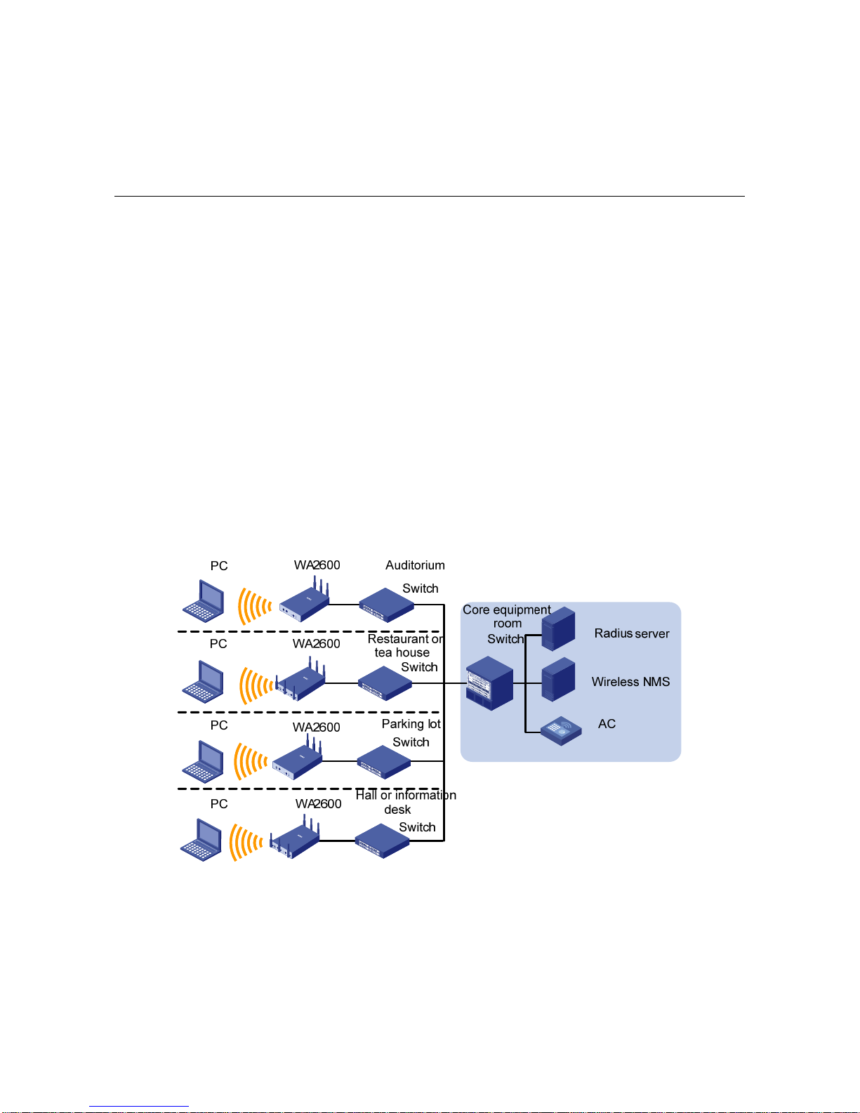
Figure 1-1 shows a typical scenario of hotspot depl oyments usi ng the
WA2600 series.
Figure 1-1 Typical networking using the WA2600 series
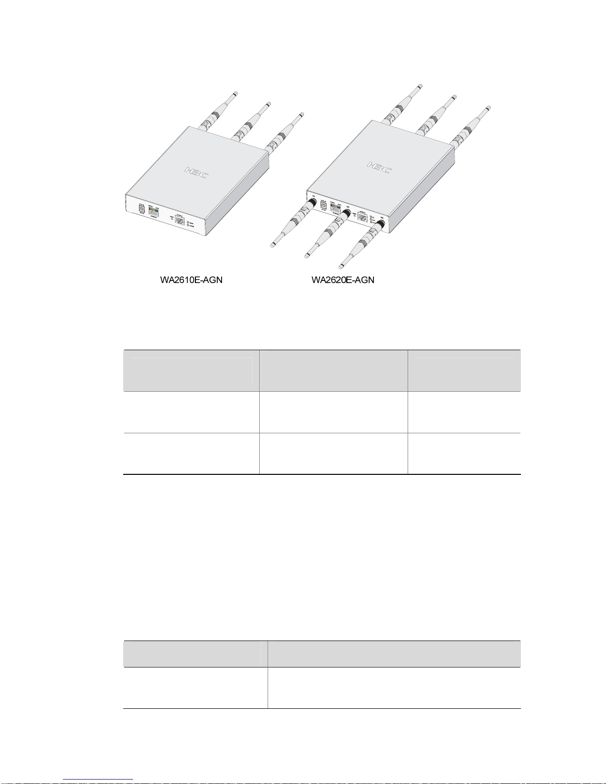
Figure 1-2 shows the appearance of the WA2600 series.
Page 9
1-2
Figure 1-2 Appearance of the WA2600 series
Table 1-1 Physical dimensions and weight of the WA2600 series
Model
Physical dimensions
(H×W×D)
Weight
H3C
WA2610E-AGN
35 × 210 × 150 mm
(1.38 × 8.27 × 5.91 in.)
1.2 kg (2.65 lb.)
H3C
WA2620E-AGN
35 × 210 × 150 mm
(1.38 × 8.27 × 5.91 in.)
1.3 kg (2.87 lb.)
Hardware Configuration
The two models of the WA2600 series have different radio
frequencies (RFs) and structures.
Table 1-2 lists the supported
protocols and the chassis material.
Table 1-2 Supported protocols and chassis material
Model Protocols and chassis material
H3C WA2610E-AGN
IEEE 802.11a/b/g/n, single-RF, sheet
metal
Page 10
1-3
Model Protocols and chassis material
H3C WA2620E-AGN
IEEE 802.11a/b/g/n, dual-RF, sheet
metal
The following describes the hardware configurations and functions of
the WA2600 se ries in detail.
LEDs
The positions and identifications of LEDs on the panel vary with the
models. For details about these LEDs, see
Table 1-3.
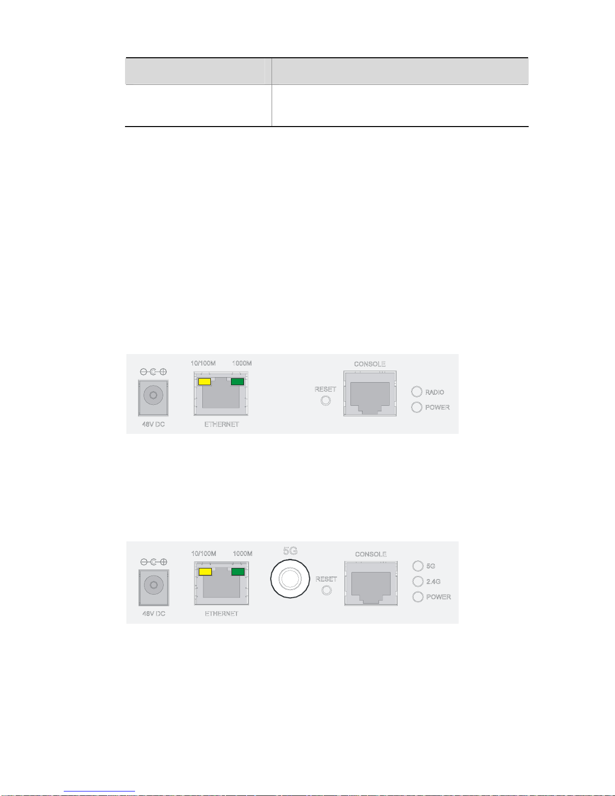
H3C WA2610E-AGN
Figure 1-3 LEDs on the H3C WA2610E-AGN
H3C WA2620E-AGN
Figure 1-4 LEDs on the H3C WA2620E-AGN
Page 11

1-4
Table 1-3 Description of the LEDs on the WA2610E-AGN and
WA2620E-AGN
LED Color QTY Meaning
POWER Green 1
Displays the power supply status:
z On: The power supply is
normal.
z Off/blinking: The power supply
is not well connected or works
abnormally.
RADIO Green 1
Displays the wireless link status:
z On: The wireless link is normal.
z Off: The wireless link is not
initialized or the link is faulty.
z Blinking slowly: The wireless
link works normally.
z Blinking rapidly: Data is being
transmitted or received.
2.4GHz
(Wireless
link LED)
Green 1
Displays the 2.4 GHz wireless link
status:
z On: The wireless link is normal.
z Off: The wireless link is not
initialized or the link is faulty.
z Blinking slowly: The wireless
link works normally.
z Blinking rapidly: Data is being
transmitted or received.
5GHz
(Wireless
link LED)
Green 1
Displays the 5 GHz wireless link
status:
z On: The wireless link is normal.
z Off: The wireless link is not
initialized or the link is faulty.
z Blinking slowly: The wireless
link works normally.
z Blinking rapidly: Data is being
transmitted or received.
Page 12

1-5
LED Color QTY Meaning
10/100M
(Ethernet
interface
LED)
Yellow 1
Displays the status of the Ethernet
interface:
z On: The Ethernet interface is in
the link-up state.
z Off: The Ethernet interface is in
the link-down state.
z Blinking: Data is being
transmitted or received at
10/100 Mbps.
1000M
(Ethernet
interface
LED)
Green 1
Displays the status of the 1000 M
Ethernet interface:
z On: The Ethernet interface is in
the link-up state.
z Off: The Ethernet interface is in
the link-down state.
z Blinking: Data is being
transmitted or received at 1000
Mbps.
Interfaces
The WA2600 se ries provide the following interfaces:
z 2.4 GHz or 5 GHz antenna interfaces
z A console interface
z An Ethernet copper interface
z A power supply interface
Page 13

1-6
In addition, the WA2600 series have a reset button and a security
slot.
Interfaces provided by the H3C WA2610E-AGN
Figure 1-5 Interfaces on the H3C WA2610E-AGN
Page 14

1-7
Interfaces provided by the H3C WA2620E-AGN
Figure 1-6 Interfaces on the H3C WA2620E-AGN
Table 1-4 describes the interfaces provided by each model.
Page 15

1-8
Table 1-4 Descriptions of interfaces on the WA2600 series WLAN
access points
Model Interface
Standards
and
protocols
Description
ANT-1
ANT-2
ANT-3
IEEE802.11
a
IEEE802.11
b
IEEE802.11
g
IEEE802.11
n
The antenna interfaces
are provided for 2.4
GHz/5 GHz dual-RF
antennas for MIMO
transmission.
Console RS/EIA-232
The console interface is
used for device
configuration and
management.
Ethernet
IEEE802.3
IEEE802.3u
IEEE802.3af
The Ethernet interface
can serve as an uplink
interface to access the
Internet or MAN, and as a
PoE interface at the same
time.
WA2610
E-AGN
Power
supply
—
The power supply
interface is used for +48
VDC power supply to the
device.
Page 16

1-9
Model Interface
Standards
and
protocols
Description
Antenna
interface
(2.4 G)
IEEE802.11
b
IEEE802.11
g
IEEE802.11
n
This antenna interface is
used to connect a 2.4
GHz antenna or a feeder.
Antenna
interface
(5 G)
IEEE802.11
a
IEEE802.11
n
This antenna interface is
used to connect a 5 GHz
antenna or a feeder.
Console RS/EIA-232
The console interface is
used for device
configuration and
management.
Ethernet
IEEE802.3
IEEE802.3u
IEEE802.3af
The Ethernet interface
can serve as an uplink
interface to access the
Internet or MAN, and a
PoE interface at the same
time, supporting
non-standard PoE power
supply.
WA2620
E-AGN
Power
supply
—
The power supply
interface is used for +48
VDC power supply to the
device.
Page 17

2-1
2 Preparing for Installation
This chapter describes the preparations for WA2600 installation,
including the preparation of installation tools, environment
examination, unpacking and inspection.
Unpacking and Inspection
Before unpacking the package, make sure that the package is intact,
without any serious damage or signs of water soaking. When
unpacking the package, avoid excessive force or collision. Otherwise,
the articles inside the package may get damaged.
After unpacking the p ackage, make sure that the following articles are
available in the package:
Table 2-1 List of articles in the package
Description QTY
WA2600 WLAN AP
1 PCS
Power adapter
1 PCS
220 VAC power cord
1 PCS
Console cable
1 PCS
Installation kit
1 set
Omni antennas
3/6 PCS
H3C WA2600 Series WLAN Access Points
Installation Manual
1 PCS
Packing list
1 PCS
Page 18

2-2
z The accessories may vary with the models. For the exact
contents of the package, refer to the packing list.
z If the contents do not check with the packing list, timely contact
your local dealer.
z If the package is found to be rusted or water soaked, stop
unpacking and contact your local dealer immediately.
z Three omni antennas are shipped with the WA2610E-AGN, while
six omni antennas are shipped with the WA2620E-AGN.
Preparing Installation Tools
When installing the AP, you may need the tools listed in Table 2-2.
Choose the appropriate tools according to the installation
environment.
Table 2-2 List of installation tools
Type of tool Indoor installation
General tools
1-meter-long rulers, marking pens, knives,
and a percussion drill with appropriate bits
Special tools
Cable strippers, crimping pliers, and RJ-45
crimping pliers
Auxiliary tools Ladders and rubber hammers
Page 19

2-3
Table 2-2 is for reference only. If you install the AP on a tabletop,
none of the above tools is required.
Examining the Installation Site
Before installation, examine the inst all ation site to make su re that the
AP will work in a good environment. You can examine the installation
site from the following two aspects.
Installation Site Selection
Keep the AP away from high temperature, dust, harmful gases,
inflammables, explosive substances, electromagnetic interference
sources (heavy-duty radars, radio stations, or electrical substations),
unstable voltage, heavy vibration, or loud noise. The installation site
should be dry, without any leakage, dripping or dew. The AP should
be at least 500 m (0.31 miles) away from the seaside and should not
face the direction of sea wind.
In engineering design, the site should be selected according to the
network planning and technical requirements of the communications
equipment, and the considerations such as climate, hydrology,
geology, earthquake, electric power, and transportation.
Temperature and Humidity Requirements
Table 2-3 lists the operating temperature and humidity req uirements.
Table 2-3 Environment specifications
Specification Range
Operating temperature (indoor) 0°C to 45°C (32°F to 113°F)
Page 20

2-4
Specification Range
Storage temperature
–40°C to +70°C (–40°F to
+158°F)
Relative humidity
(noncondensing)
10% to 95%
Power Supply
Check that the power supply of the installation site is stable. The
centralized AC power system consisting of the AC mains, UPS, and
user-supplied diesel generator should be:
z Easy to connect
z Safe to operate
z Flexible to dispatch
z Convenient to maintain
The low-voltage power supply should adopt the single-phase
three-wire system.
Table 2-4 lists the nominal voltage and frequency
of the low-voltage AC power supply.
Table 2-4 Nominal voltage and frequency of the low-voltage AC
power supply
Power supply Nominal voltage Stable frequency
Single-phase
three-wire (V)
100 VAC to 240
VAC
50/60 Hz
Page 21

2-5
z If the voltage is unstable, a voltage regulator or stabilizer is
required.
z An uninterrupted power supply (UPS) is required for
uninterrupted communication.
Grounding and Lightning Protection
Table 2-5 Grounding and lightning protection requireme nts
Item Requirements
Grounding
resistance
z The grounding resistance is typically required to
be less than 5 ohms, and less than 10 ohms in an
area that has less than 20 thunderstorm days a
year. If an angle iron is to be buried into the earth
as the earthing conductor, the grounding
resistance is required to be less than 10 ohms. If
the installation site has a high earth resistance
rate, it is recommended to spray some salt water
or resistance-reducing agent on the eart h around
the buried earthing conductor to reduce the
resistance rate of the earth.
z The top of the earthing conductor should be at
least 0.7 m (2.30 ft) away from the ground
surface. In cold areas, the earthing conductor
should be buried below the frozen soil layer.
Page 22

2-6
Item Requirements
Protection
grounding
z If a grounding strip is available at the site, attach
the yellow-green PGND cable of the AP to the
grounding strip. The PGND cable must have a
cross-section area of at least 6 mm
2
(0.01 in2)
and a length not longer than 3 m (9.84 ft).
z If no grounding strip is available at the site,
hammer a 0.5 m (1.64 ft) or longer angle iron or
steel tube into the earth. The angle iron should be
sized at least 50 × 50 × 5 mm (1.97 × 1.97 × 0.20
in.); the steel tube should have a wall thi ckness of
at least than 3.5 mm (0.18 in.) and be zinc-plated.
Weld the yellow-green grounding cable to the
angel iron or steel tube and treat the joint for
corrosion protection. With a cross-section area of
at least 6 mm
2
(0.01 in2), the grounding cable
should be as short as possible. Do not coil the
cable.
z Make sure the lightning arresters of all devices
and the peering devices connected to these
devices are well grounded.
Grounding
lead
The grounding lead is a metal conductor connecting
the grounding strip to the grounding grid. The PGND
cable of the device should be attached to the
grounding strip. The grounding lead should not be
longer than 30 m (98.43 ft). A zinc-plated flat steel
with a cross-section area of 40 × 4 mm (1.57 × 0.16
in) or 50 × 5 mm (1.97 × 0.20 in) is recommended.
The grounding strip and the grounding lead shoul d
be jointed using a 35 mm2 yellow-green PGND
cable or directly welded together with the joint
treated for corrosion protection.
AC power
grounding
z Make sure you use the power cable with a PE
terminal but not the cables with only L and N
wires.
z It is strictly prohibited to connect the N wire of the
power cable to the protection ground of any other
communications device, and the L and N wires
must be connected correctly.
Page 23

2-7
Item Requirements
Lightning
rod
In a plain area, the protection angel of the lightning
rod should be less than 45 degrees. In a
mountainous area or lightning intensified area, the
protection angle should be less than 30 deg rees.
The lightning protection ground (for example, the
ground of the lightning rod) and the protection
ground of the equipment room should be connected
to the same earthing conductor.
Feeder
z The antenna support is ready and in accordance
with the design requirement.
z A feeder lightning rod is already installed and
grounded according to the design requirement.
Outdoor
lightning
arresters
In case of outdoor installation, a power supply
lightning arrester, a feeder lightning arrester and a
network port lightning arrester are required. The
power supply lightning arrester and feeder lightning
arrester are located close to the AP while the
network port lightning arrester is installed close to
the peer device where the network cable goes out of
the room.
Network
cable
In case of outdoor installation, make sure to use a
shielded network cable and the interconnected
devices are well grounded.
After you have completed the preparations, you can st art installing the
AP. For details, refer to
3 "Installing the AP" on page 3-1.
Page 24

3-1
3 Installing the AP
The WA2600 series WLAN APs can be directly fixed onto a wall by
using the wall-mounting brackets. The following introduces the
wall-mounting procedure of the WA2600 series in detail.
Installation Flowchart
Figure 3-1 shows the installation flowchart of the WA2600 series.
Figure 3-1 Installation flowchart
End
Determine the
installation position
Install the AP
Connect the power
supply and the networ k
Start
Determining the Installation Position
Determine the installation position by observing the following
principles:
z Leave as few obstacles (such as wall and ceiling) as possible
between the AP and the wireless stations.
Page 25

3-2
z Keep the AP far away from electronic devices (such as
microwave ovens) that may generate RF noise.
z Install the AP in a place where it will not hinder people’s daily
work and life.
Make sure the ceiling is strong enough and the structure is suitable in
case of ceiling mounting. Reinforce the ceiling if needed. A padlock is
required for ceiling mounting to prevent any falloff in case of shocks.
A Blossom 071 padlock or similar padlock is re commended.
Installing the AP on a Wall
The following describes how to inst all a WA2600 series AP on a wall:
z Installing the Wall-Mounting Bracket on the Wall
z Installing the AP on the Wall-Mounting Bracket
z Locking the AP onto the Wall-Mounting Bracket (Optional)
Installing the Wall-Mounting Bracket on the Wall
1) Drill holes 6 mm (0.24 in) in diameter on the wall where the AP is to
be mounted. The drilled holes must correspond to those in the
wall-mounting bracket. There are eight installation holes in total in
the wall-mounting bracket. Select at least four of them for the
installation.
Page 26

3-3
Figure 3-2 Screw hole locations and screw hole size
49.0
44.6
22.3
49.1
49.1
150.0
75.0
62.9
104.0
2) Insert the pointed end of anchors into the drilled holes and tap the
flat end of anchors with a rubber hammer until they are all flush
with the wall surface.
3) Align the holes in the wall-mounting bracket with the anchors and
insert screws through the installation holes into the anchors, as
shown in
Figure 3-3.
4) Adjust the position of the wall-mounting bracket and tighten the
screws.
Page 27

3-4
Figure 3-3 Install the wall-mounting bracket
Install the wall-mounting bracket with the arrow on the bracket
pointing upwards.
Page 28

3-5
Installing the AP on the Wall-Mounting Bracket
The installation procedure is the same for both the WA2610E-AGN
and WA2620E-AGN. The WA2610E-AGN is taken as an example in
this manual.
1) Align the AP with the hooks on the wall-mounting bracket and
hang the AP on the bracket. See (1) in
Figure 3-4.
2) Press the AP downward to fix it. See (2) in
Figure 3-4.
Page 29

3-6
Figure 3-4 Fix the AP onto the wall-mounting bracket
Expansion
screw
Hook
(1)
(2)
Locking the AP onto the Wall-Mounting Bracket (Optional)
The WA2600 se ries APs have a security slot on the top, which ca n be
used to lock the AP onto the wall-mounting bracket to prevent theft.
Follow these steps to lock the AP onto the wall-mounting bracket:
1) Insert the locking plate into the security slot on the top of the AP.
See (1) in
Figure 3-5.
2) Turn the locking plate counterclockwise until the hole on the
locking plate is aligned with the hole in the wall-mounting bracket.
See (2) in
Figure 3-5.
3) Put the latch through the two holes that are aligned in step 2. See
(3) in
Figure 3-5.
4) Lock the latch with a lock.
Page 30

3-7
Figure 3-5 Lock the AP onto the wall-mounting bracket
Locking plate
Latch
(1
)
(2)
Locking hole
Wall-mounting bracket
(3)
Security slot
The lock is user supplied.
Page 31

3-8
Connecting the Power Supply
Local Power Supply
Connect the AP to the power source through the power adapter, as
shown in
Figure 3-6.
Figure 3-6 Local power supply connection
Power over Ethernet
If the uplink device of the AP is a PoE-capable switch or the like, use
an Ethernet cable to connect the Ethernet interface of the AP to the
PoE-capable device.
Figure 3-7 PoE connection
Page 32

3-9
z In the PoE mode, you do not need to connect the power interface
to a power source. You only need to connect one end of an
Ethernet cable to the Ethernet interface of the AP and the other
end to an Ethernet interface of the PoE-capable device (for
example, an Ethernet switch).
z Identify the silkscreen on the device to avoid taking the console
interface for the Ethernet interface, or vice versa.
z The WA2620E-AGN supports only non-standard PoE power
supply.
Connecting the AP to the Network
The WA2600 series can access the Internet or MAN through the
Ethernet uplink interface. Connect the Ethernet interface of the AP to
an Ethernet interface of an Ethernet switch to implement Internet or
MAN access, as shown in
Figure 3-8.
Figure 3-8 Connect the AP to the network
 Loading...