

Page 1

H3C WA Series WLAN Access Points
ACL and QoS Configuration Guide
Hangzhou H3C Technologies Co., Ltd.
http://www.h3c.com
Document Version: 6W100-20100910
Page 2

Copyright © 2010, Hangzhou H3C Technologies Co., Ltd. and its licensors
All Rights Reserved
No part of this manual may be reproduced or transmitted in any form or by any means without prior
written consent of Hangzhou H3C Technologies Co., Ltd.
Trademarks
Notice
H3C, , Aolynk, , H3Care,
SecPro, SecPoint, SecEngine, SecPath, Comware, Secware, Storware, NQA, VVG, V
, TOP G, , IRF, NetPilot, Neocean, NeoVTL,
2
G, VnG, PSPT,
XGbus, N-Bus, TiGem, InnoVision and HUASAN are trademarks of Hangzhou H3C Technologies Co.,
Ltd.
All other trademarks that may be mentioned in this manual are the property of their respective owners.
The information in this document is subject to change without notice. Every effort has been made in the
preparation of this document to ensure accuracy of the contents, but all statements, information, and
recommendations in this document do not constitute the warranty of any kind, express or implied.
Page 3

Preface
The H3C WA documentation set inclu des 10 configuration guides, which describe the soft ware features
for the H3C WA series WLAN access points and guide you through the software configuration
procedures. These configuration guides also provide configuration examples to help you apply the
software features to different network scenarios.
The ACL and QoS Configuration Guide describes ACL and QoS configurations.
This preface includes:
z Audience
z Conventions
z About the H3C WA Documentation Set
z Obtaining Documentation
z Documentation Feedback
Audience
This documentation is intended for:
z Network planners
z Field technical support and servicing engineers
z Network administrators working with the WA series
Conventions
This section describes the conventions used in this documentation set.
Command conventions
Convention Description
Boldface Bold
italic
[ ]
{ x | y | ... }
[ x | y | ... ]
{ x | y | ... } *
text represents commands and keywords that you enter literally as shown.
Italic text represents arguments that you replace with actual values.
Square brackets enclose syntax choices (keywords or arguments) that are
optional.
Braces enclose a set of required syntax choices separated by vertical bars,
from which you select one.
Square brackets enclose a set of optional syntax choices separated by vertical
bars, from which you select one or none.
Asterisk marked braces enclose a set of required syntax choices separated by
vertical bars, from which you select at least one.
[ x | y | ... ] *
&<1-n>
Asterisk marked square brackets enclose optional syntax choices separated by
vertical bars, from which you may select multiple choices or none.
The argument or keyword and argument combination before the ampersand (&)
sign can be entered 1 to n times.
Page 4
Convention Description
# A line that starts with a pound (#) sign is comments.
GUI conventions
Convention Description
Boldface
>
Window names, button names, field names, and menu items are in Boldface.
For example, the
Multi-level menus are separated by angle brackets. For example,
Folder
>
.
New User
Symbols
Convention Description
Means reader be extremely careful. Improper operation may cause bodily
injury.
Means reader be careful. Improper operation may cause data loss or damage to
equipment.
Means an action or information that needs special attention to ensure
successful configuration or good performance.
Means a complementary description.
Means techniques helpful for you to make configuration with ease.
About the H3C WA Documentation Set
window appears; click OK.
File
>
Create
The H3C WA documentation set includes:
Category Documents Purposes
Product
description and
specifications
Hardware
specifications
and installation
Software
configuration
Marketing brochures Describe product specifications and benefits.
Technology white papers
Compliance and safety
manual
Quick start
Installation guide
Getting started guide
Configuration guides Describe software features and configuration procedures.
Command references Provide a quick reference to all available commands.
Provide an in-depth description of software features and
technologies.
Provides regulatory information and the safety instructions
that must be followed during installation.
Guides you through initial installation and setup procedures to
help you quickly set up and use your AP with the minimum
configuration.
Guides you through hardware specifications and installation
methods to help you install your AP.
Guides you through the main functions of your AP, and
describes how to install and log in to your AP, perform basic
configurations, maintain software, and troubleshoot your AP.
Page 5

Category Documents Purposes
User FAQ
Operations and
maintenance
Release notes
Obtaining Documentation
You can access the most up-to-date H3C product documentation on the World Wide Web at
http://www.h3c.com.
Click the links on the top navigation bar to obtain different categories of product documentation:
[Technical Support & Documents > Technical Documents] – Provides hardware installation, software
upgrading, getting started, and software feature configuration and maintenance documentation.
[Products & Solutions] – Provides information about products and technologies, as well as solutions.
[Technical Support & Documents > Software Download] – Provides the documentation released with
the software version.
Provides answers to some of the most frequently asked
questions on how to troubleshoot your AP.
Provide information about the product release, including the
version history, hardware and software compatibility matrix,
version upgrade information, technical support information,
and software upgrading.
Documentation Feedback
You can e-mail your comments about product documentation to info@h3c.com.
We appreciate your comments.
Page 6

Table of Contents
1 Applicable Models and Software Versions·····························································································1-1
2 Feature Matrix············································································································································2-1
3 Command/Parameter Matrix·····················································································································3-1
4 ACL Configuration·····································································································································4-1
ACL Overview·········································································································································4-1
ACL Categories·······························································································································4-2
ACL Numbering and Naming ··········································································································4-2
Match Order·····································································································································4-2
ACL Rule Numbering·······················································································································4-4
Implementing Time-Based ACL Rules····························································································4-4
IPv4 Fragments Filtering with ACLs································································································4-4
ACL Configuration Task List ···················································································································4-4
Configuring an ACL·································································································································4-5
Creating a Time Range ···················································································································4-5
Configuring a WLAN ACL················································································································4-5
Configuring a Basic ACL ·················································································································4-6
Configuring an Advanced ACL········································································································4-7
Configuring an Ethernet Frame Header ACL··················································································4-9
Copying an ACL ····························································································································4-10
Displaying and Maintaining ACLs·········································································································4-10
ACL Configuration Examples················································································································4-10
IPv4 ACL Configuration Example··································································································4-10
IPv6 ACL Configuration Example··································································································4-12
5 QoS Overview ············································································································································5-1
Introduction to QoS·································································································································5-1
Introduction to QoS Service Models ·······································································································5-1
Best-Effort Service Model················································································································5-1
IntServ Service Model ·····················································································································5-2
DiffServ Service Model····················································································································5-2
QoS Techniques Overview ·····················································································································5-2
Applying QoS Techniques in a Network··························································································5-3
QoS Processing Flow in an AP ·······································································································5-4
6 QoS Policy Configuration·························································································································6-1
QoS Configuration Approach Overview··································································································6-1
Non-Policy Approach·······················································································································6-1
Policy Approach·······························································································································6-1
Configuring a QoS Policy························································································································6-1
Defining a Class ······························································································································6-2
Defining a Traffic Behavior··············································································································6-2
i
Page 7

Defining a QoS Policy and Applying the QoS Policy to an Interface ··············································6-3
Displaying and Maintaining QoS Policies ·······························································································6-3
7 Priority Mapping Configuration················································································································7-1
Introduction to Packet Precedences·······································································································7-1
IP Precedence and DSCP Values···································································································7-1
802.1p Priority ·································································································································7-2
802.11e Priority ·······························································································································7-3
Priority Mapping Overview······················································································································7-3
Introduction to Priority Mapping·······································································································7-3
Introduction to Priority Mapping Tables···························································································7-4
Priority Mapping Configuration Task List································································································7-5
Configuring Priority Mapping···················································································································7-6
Configuring a Priority Mapping Table······························································································7-6
Configuring a Port to Trust Packet Priority for Priority Mapping······················································7-6
Changing the Port Priority of an Interface·······················································································7-7
Displaying and Maintaining Priority Mapping··························································································7-7
Priority Mapping Configuration Example·································································································7-7
8 Index ···························································································································································8-1
ii
Page 8
z The models listed in this document are not applicable to all regions. Please consult your local sales
office for the models applicable to your region.
z Read this chapter before using an H3C WA series WLAN access point.
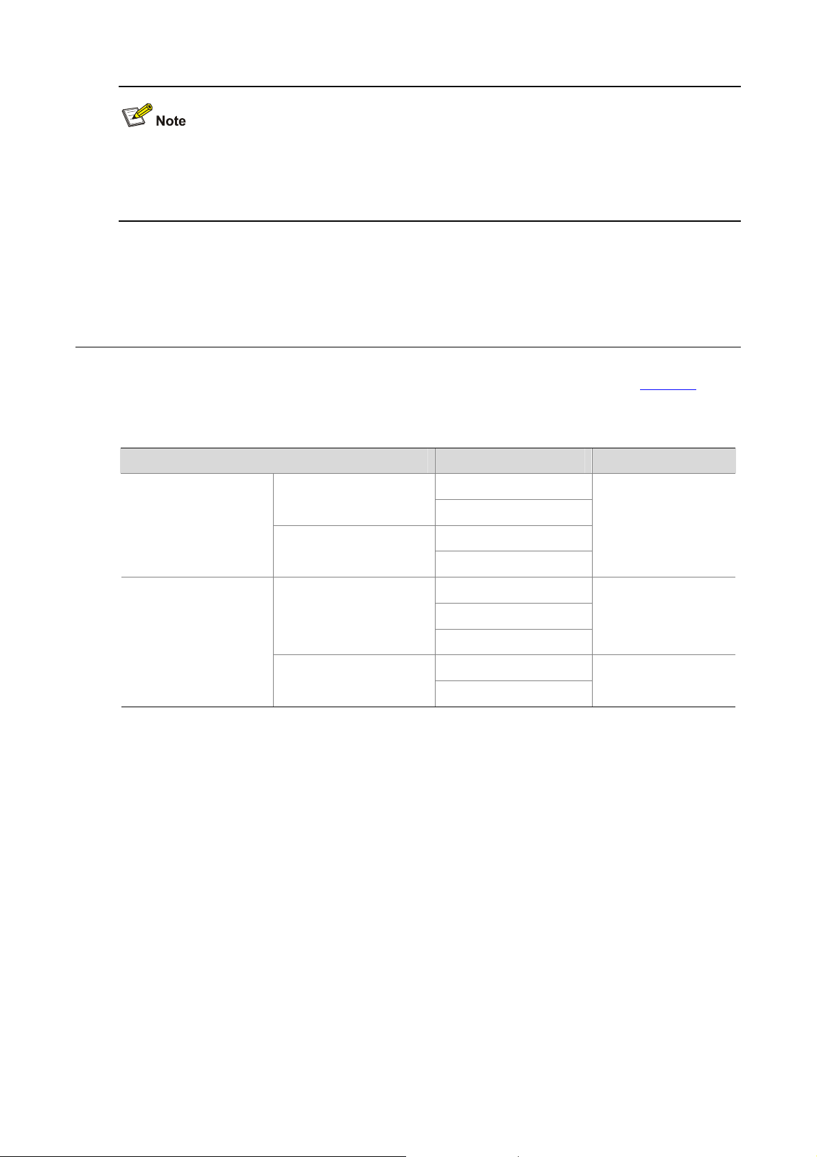
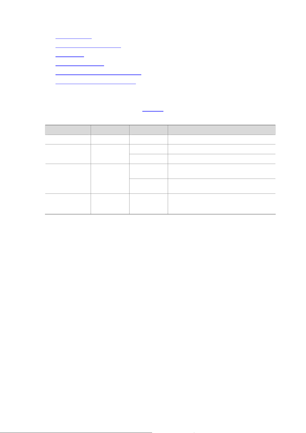
1 Applicable Models and Software Versions
H3C WA series WLAN access points include the WA2200 series and WA2600 series. Table 1-1 shows
the applicable models and software versions.
Table 1-1 Applicable models and software versions
Series Model Software version
WA2200 series
WA2600 series
WA2200 series access
points (indoors)
WA2200 series access
points (outdoors)
WA2600 series access
points (indoors)
WA2600 series access
points (enhanced)
WA2210-AG
WA2220-AG
WA2210X-G
WA2220X-AG
WA2610-AGN
WA2612-AGN
WA2620-AGN
WA2610E-AGN
WA2620E-AGN
R 1115
R 1106
R 1109
1-1
Page 9
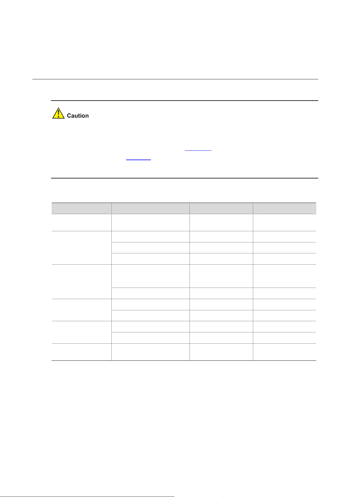
2 Feature Matrix
z Support of the H3C WA series WLAN access points for features, commands and parameters may
vary by device model. See this document for more information.
z For information about feature support, see Table 2-1. For information about command and
parameter support, see
z The term AP in this document refers to common APs, wireless bridges, or mesh APs.
Table 2-1 Feature matrix
Document Feature WA2200 series WA2600 series
Table 3-1.
Fundamentals
Configuration Guide
WLAN Configuration
Guide
Layer 2 – LAN
Switching
Configuration Guide
Layer 3 – IP Services
Configuration Guide
IP Multicast
Configuration Guide
Security Configuration
Guide
HTTPS Not supported Supported
802.11n radio mode Not supported Supported
802.11n bandwidth mode Not supported Supported
802.11n rate configuration Not supported Supported
Supported on
Optical Ethernet interface
GE interface Not supported Supported
DHCP server configuration Not supported Supported
DHCPv6 configuration Not supported Supported
IGMP snooping configuration Not supported Supported
MLD snooping configuration Not supported Supported
SSH2.0 Not supported Supported
WA2210X-G/WA2220XAG only
Not supported
2-1
Page 10
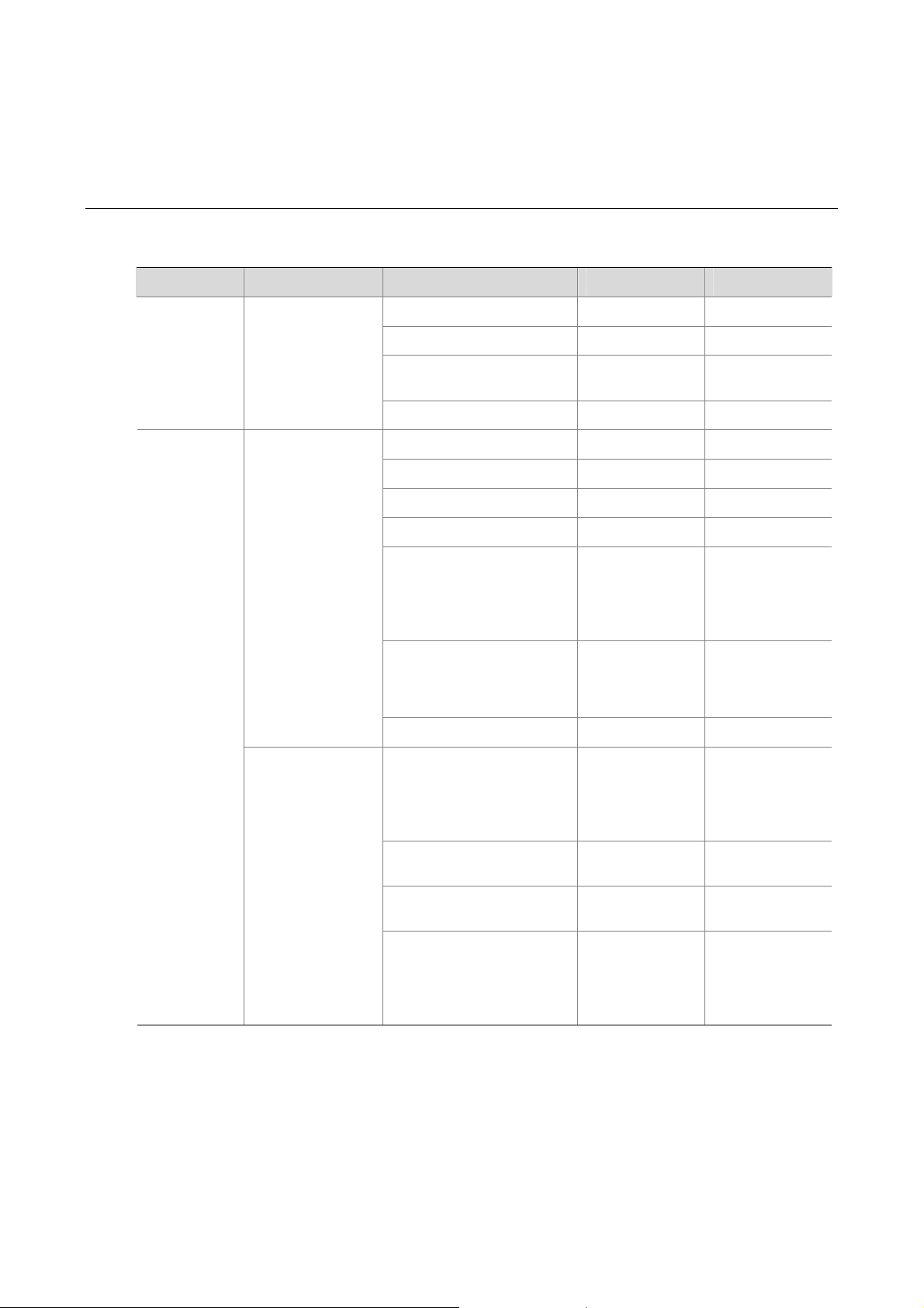
3 Command/Parameter Matrix
Table 3-1 Command/Parameter matrix
Document Module Command/Parameter WA2200 series WA2600 series
Fundamentals
Command
Reference
WLAN
Command
Reference
HTTP commands
WLAN service
commands
display ip https
ip https acl
ip https certificate
access-control-policy
ip https enable
a-mpdu enable
a-msdu enable
channel band-width
client dot11n-only
preamble
radio-type
short-gi enable
dot11a { disabled-rate |
mandatory-rate |
supported-rate
{
long
short }
|
} rate-value
Not supported Supported
Not supported Supported
Not supported Supported
Not supported Supported
Not supported Supported
Not supported Supported
Not supported Supported
Not supported Supported
Only APs that
support the
802.11b/g radio
mode support this
command.
Keywords
dot11an
dot11gn
supported
Not supported Supported
Only APs that
support 802.11a
radio mode
support this
command.
and
not
Only APs that
support the
802.11b/g radio
mode support this
command.
Supported
Only APs that
support 802.11a
radio mode
support this
command.
WLAN RRM
commands
dot11n mandatory
maximum-mcs
dot11n support
maximum-mcs
power-constraint
power-constraint
3-1
Not supported Supported
Not supported Supported
Only APs that
support the
802.11a radio
mode support this
command.
Only APs that
support the
802.11a radio
mode support this
command.
Page 11

Document Module Command/Parameter WA2200 series WA2600 series
The maximum
number of
broadcast packets
that can be
forwarded on an
Ethernet interface
per second
broadcast-suppression
pps
{ ratio |
max-pps }
pps
ranges from 1 to
148810.
max-pps
pps
max-pps
ranges from 1 to
1488100.
Layer 2 – LAN
Switching
Command
Reference
Layer 3 - IP
Services
Command
Reference
The maximum
number of multicast
packets allowed on
an Ethernet
interface per
second
The maximum
number of unknown
unicast packets
allowed on an
Ethernet interface
per second
DHCP commands
DHCPv6
commands
multicast-suppression
{ ratio |
unicast-suppression
|
DHCP server configuration
commands
display ipv6 dhcp client
[
interface-number ]
display ipv6 dhcp client
statistics [ interface
interface-type
interface-number ]
display ipv6 dhcp duid
reset ipv6 dhcp client
statistics [ interface
interface-type
interface-number ]
pps
pps
max-pps }
interface
max-pps }
interface-type
{ ratio
Not supported Supported
pps
max-pps
ranges from 1 to
148810.
pps
max-pps
ranges from 1 to
148810.
Not supported Supported
Not supported Supported
Not supported Supported
Not supported Supported
pps
max-pps
ranges from 1 to
1488100.
pps
max-pps
ranges from 1 to
1488100.
3-2
Page 12

z The models listed in this document are not applicable to all regions. Please consult your local sales
office for the models applicable to your region.
z Support of the H3C WA series WLAN access points (APs) for features may vary by AP model. For
more information, see Feature Matrix.
z The interface types and the number of interfaces vary by AP model.
z The term AP in this document refers to common APs, wireless bridges, and mesh APs.
4 ACL Configuration
This chapter includes these section s:
z ACL Overview
z ACL Configuration Task List
z Configuring an ACL
z Creating a Time Range
z Configuring a WLAN ACL
z Configuring a Basic ACL
z Configuring an Advanced ACL
z Configuring an Ethernet Frame Header ACL
z Copying an ACL
z Displaying and Maintaining ACLs
z ACL Configuration Examples
Unless otherwise stated, ACLs refer to both IPv4 and IPv6 ACLs throughout this document.
ACL Overview
An access control list (ACL) is a set of rules (or permit or deny statements) for identifying traffic based
on criteria such as source IP address, destination IP address, and port number.
ACLs are essentially used for packet filtering. A packet filter drops packets that match a deny rule and
permits packets that match a permit rule. ACLs are also widely used by many modules, for example,
QoS and IP routing, for traffic identification.
This section covers these topics:
4-1
Page 13
z ACL Categories
z ACL Numbering and Naming
z Match Order
z ACL Rule Numbering
z Implementing Time-Based ACL Rules
z IPv4 Fragments Filtering with ACLs
ACL Categories
ACLs fall into four categories, as shown in Table 4-1.
Table 4-1 ACL categories
Category ACL number IP version Match criteria
WLAN ACLs 100 to 199 IPv4 Wireless client SSID
Basic ACLs 2000 to 2999
Advanced ACLs 3000 to 3999
Ethernet frame
header ACLs
4000 to 4999 IPv4
ACL Numbering and Naming
Each ACL category has a unique range of ACL numbers. When creating an ACL, you must assign it a
number for identification, and in addition, you can also assign the ACL a name for the ease of
identification. After creating an ACL with a name, you can neither rename it nor delete its name.
You cannot assign a name for a WLAN ACL.
For a WLAN and Ethernet frame header, the ACL number and name must be globally unique. For an
IPv4 basic or advanced A CLs, its ACL number and name must be unique among all IPv4 ACLs, and for
an IPv6 basic or advanced ACL, among all IPv6 ACLs. You can assign an IPv4 ACL the same number
and name as an IPv6 ACL.
IPv4 Source IPv4 address
IPv6 Source IPv6 address
IPv4
IPv6
Source/destination IPv4 address, protocols over
IPv4, and other Layer 3 and Layer 4 header fields
Source/destination IPv6 address, protocols over
IPv6, and other Layer 3 and Layer 4 header fields
Layer 2 header fields, such as source and
destination MAC addresses, 802.1p priority, and
link layer protocol type
Match Order
The rules in an ACL are sorted in certain order. When a packet matches a rule, the device stops the
match process and performs the action defined in the rule. If an ACL contain s overlapping or conflicting
rules, the matching result and action to take depend on the rule order.
Two ACL match orders are available:
z config – Sorts ACL rules in ascending order of rule ID. A rule with a lower ID is matched before a
rule with a higher ID. If you use this approach, check rule content and order carefully.
4-2
Page 14

z auto – Sorts ACL rules in depth-first order. Depth-first ordering ensures that any subset of a rule is
always matched before the rule.
Table 4-2 lists the sequence of tie breakers that depth-first
ordering uses to sort rules for each type of ACL.
The match order of WLAN ACLs can only be config.
Table 4-2 Sort ACL rules in depth-first order
ACL category Sequence of tie breaker
1) VPN instance
IPv4 basic ACL
IPv4 advanced ACL
IPv6 basic ACL
IPv6 advanced ACL
Ethernet frame
header ACL
2) More 0s in the source IP address wildcard (more 0s means a narrower IP address
range)
3) Smaller rule ID
1) VPN instance
2) Specific protocol type rather than IP (IP represents any protocol over IP)
3) More 0s in the source IP address wildcard mask
4) More 0s in the destination IP address wildcard
5) Narrower TCP/UDP service port number range
6) Smaller ID
1) Longer prefix for the source IP address (a longer prefix means a narrower IP
address range)
2) Smaller ID
1) Specific protocol type rather than IP (IP represents any protocol over IPv6)
2) Longer prefix for the source IPv6 address
3) Longer prefix for the destination IPv6 address
4) Narrower TCP/UDP service port number range
5) Smaller ID
1) More 1s in the source MAC address mask (more 1s means a smaller MAC
address)
2) More 1s in the destination MAC address mask
3) Smaller ID
z The AP does not support ACL rules with the VPN instance attribute.
z A wildcard mask, also called an inverse mask, is a 32-bit binary and represented in dotted decimal
notation. In contrast to a network mask, the 0 bits in a wildcard mask represent 'do care' bits, while
the 1 bits represent 'don’t care bits'. If the 'do care' bits in an IP address identical to the 'do care' bits
in an IP address criterion, the IP address matches the criterion. All 'don’t care' bits are ignored. The
0s and 1s in a wildcard mask can be noncontiguous. For example, 0.255.0.255 is a valid wildcard
mask.
4-3
Page 15

ACL Rule Numbering
What is the ACL rule numbering step
If you do not assign an ID for the rule you are creating, the system a utomatically assigns it a rule ID. The
rule numbering step sets the increment by which the system automatically numb ers rules. For example,
the default ACL rule numbering step is 5. If you do not assign IDs to rules you are creating, they are
numbered 0, 5, 10, 15, and so on. The wider the numberin g step, the more rules you can insert between
two rules.
By introducing a gap between rules rather than contiguously numberin g rules, you have the flexibility of
inserting rules in an ACL. This feature is import ant for a config order ACL, where ACL rule s are matched
in ascending order of rule ID.
Automatic rule numbering and re-numbering
The ID automatically assigned to an ACL rule t akes the nearest higher multiple of the numbe ring step to
the current highest rule ID, starting with 0.
For example, if the numbering step is 5 (the default), and there are five ACL rul es numbered 0, 5, 9, 10,
and 12, the newly defined rule will be numbered 15. If the ACL does not contain any rule, the first rule
will be numbered 0.
Whenever the step changes, the rules are renumbered, starting from 0. For example, if there are five
rules numbered 5, 10, 13, 15, and 20, changing the step from 5 to 2 causes the rules to be renumbered
0, 2, 4, 6 and 8.
Implementing Time-Based ACL Rules
You can implement ACL rules based on the time of day by applying a time range to them. A time-based
ACL rule takes effect only in any time periods specified by the time range.
Two basic types of time ran ge are available:
z Periodic time range, which recurs periodically on a day or days of the week.
z Absolute time range, which represents only a period of time and does not recur.
Y ou may appl y a time range to ACL rules before or after you create it. However , the rules using the time
range can take effect only after you define the time range.
IPv4 Fragments Filtering with ACLs
Traditional packet filtering matches only first fragments of IPv4 packets, and allows all subsequent
non-first fragments to pass through. Attackers can fabricate non-first fragments to attack networks.
To avoids the risks, the H3C ACL implementation:
z Filters all fragments by default, including non-first fragments.
z Provides standard and exact match modes for matching ACLs that contain advanced attributes
such as TCP/UDP port number and ICMP type. Standard match is the default mode. It considers
only Layer 3 attributes. Exact match considers all header attributes defined in IPv4 ACL rules.
ACL Configuration Task List
IPv4 configuration task list
Complete the following tasks to configure an IPv4 ACL:
4-4
Page 16

Task Remarks
Creating a Time Range Optional
Configuring a WLAN ACL
Configuring an IPv4 basic ACL
Configuring an IPv4 advanced ACL
Configuring an Ethernet Frame Header ACL
Copying an IPv4 ACL Optional
IPv6 ACL configuration task list
Complete the following tasks to configure an IPv6 ACL:
Creating a Time Range Optional
Configuring an IPv6 basic ACL
Configuring an IPv6 Advanced ACL
Copying an IPv6 ACL Optional
Configuring an ACL
Creating a Time Range
Required
Configure at least one task.
Task Remarks
Required
Configure at least one task.
Follow these steps to create a time range:
To do… Use the command… Remarks
Enter system view
Create a time
range
system-view
time-range
days [
date1 [ to time2 date2 ] | to time2 date2 }
You may create time ranges identified with the same name. They are regarded as one time range
whose active period is the result of ORing periodic ones, ORing absolute ones, and ANDing periodic
and absolute ones.
You may create a maximum of 256 uniquely named time ranges, each with 32 periodic time ranges at
most and 12 absolute time ranges at most.
Configuring a WLAN ACL
WLAN ACLs match packets based on SSIDs of wireless clients.
Follow these steps to configure a WLAN ACL:
To do… Use the command… Remarks
time-range-name { start-time to end-time
from
time1 date1 ] [ to time2 date2 ] |
from
time1
––
Required
By default, no time range
exists.
Enter system view
system-view
––
4-5
Page 17

To do… Use the command… Remarks
Create a WLAN ACL and
enter its view
Configure a description
for the WLAN ACL
Set the rule numbering
step
Create or edit a rule
Configure or edit a rule
description
Configuring a Basic ACL
Configuring an IPv4 basic ACL
IPv4 basic ACLs match packets based on only source IP address.
Follow these steps to configure an IPv4 basic ACL:
acl number
description
step
step-value
rule
[ rule-id ] {
deny
rule
ssid
} [
rule-id
acl-number
text
permit
ssid-name ]
comment
Required
By default, no ACL exists.
WLAN ACLs are numbered in the range 100 to 199.
Optional
By default, a WLAN ACL has no ACL description.
Optional
5 by default.
Required
|
By default, a WLAN ACL does not contain any rule.
To create or edit multiple rules, repeat this step.
Optional
text
By default, a WLAN ACL rule has no description.
To do… Use the command… Remarks
Enter system view
Create an IPv4 basic ACL
and enter its view
Configure a description
for the IPv4 basic ACL
Set the rule numbering
step
Create or edit a rule
Configure or edit a rule
description
system-view
acl number
name
[
match-order
[
config
description
step
rule
[ rule-id ] {
permit
logging | source
sour-wildcard |
time-range
time-range-name ] *
rule
rule-id
acl-number
acl-name ]
} ]
text
step-value
fragment |
} [
comment
auto
{
deny
{ sour-addr
any
} |
|
|
text
––
Required
By default, no ACL exists.
IPv4 basic ACLs are numbered in the range 2000
to 2999.
You can use the
enter the view of an existing named IPv4 ACL.
Optional
By default, an IPv4 basic ACL has no ACL
description.
Optional
5 by default.
Required
By default, an IPv4 basic ACL does not contain
any rule.
To create or edit multiple rules, repeat this step.
logging
The
module that uses the ACL supports logging.
Optional
By default, an IPv4 ACL rule has no rule
description.
acl name
keyword takes effect only when the
acl-name command to
Configuring an IPv6 basic ACL
Follow these steps to configure an IPv6 basic ACL:
4-6
Page 18

To do… Use the command… Remarks
Enter system view
Create an IPv6 basic
ACL view and enter its
view
Configure a description
for the IPv6 basic ACL
Set the rule numbering
step
Create or edit a rule
Configure or edit a rule
description
system-view
acl ipv6 number
name
[
acl6-name ]
match-order
[
description
step
step-value
rule
[ rule-id ] {
fragment | logging
[
{ ipv6-address prefix-length |
ipv6-address/prefix-length |
any
time-range
} |
time-range-name ] *
rule
rule-id
acl6-number
auto
{
text
deny
comment
config
|
permit
|
source
|
text
––
Required
By default, no ACL exists.
IPv6 basic ACLs are numbered in the range 2000
to 2999.
} ]
You can use the
command to enter the view of an existing named
IPv6 ACL.
Optional
By default, an IPv6 basic ACL has no ACL
description.
Optional
5 by default
Required
}
By default, an IPv6 basic ACL does not contain
any rule.
To create or edit multiple rules, repeat this step.
logging
The
module using the ACL supports logging.
Optional
By default, an IPv6 basic ACL rule has no rule
description.
acl ipv6 name
keyword takes effect only when the
acl6-name
Configuring an Advanced ACL
Configuring an IPv4 advanced ACL
IPv4 advanced ACLs match packets based on source and destination IP addresses, protocols over IP,
and other protocol header information, such as TCP/UDP source and destination port numbers, TCP
flags, ICMP message types, and ICMP message codes.
IPv4 advanced ACLs also allow you to filter packets based on three priority criteria: type of service (ToS),
IP precedence, and differentiated services codepoint (DSCP) priority.
Compared with IPv4 basic ACLs, IPv4 advanced ACLs allow of more flexible and accurate filtering.
Follow these steps to configure an IPv4 advanced ACL:
To do… Use the command… Remarks
Enter system view
Create an IPv4 advanced
ACL and enter its view
system-view
acl number
acl-name ] [
config
acl-number [
match-order
} ]
name
auto
{
––
Required
By default, no ACL exists.
IPv4 advanced ACLs are numbered in the
|
range 3000 to 3999.
You can use the
command to enter the view of an existing
named IPv4 ACL.
acl name
acl-name
Configure a description for
the IPv4 advanced ACL
description
text
Optional
4-7
By default, an IPv4 advanced ACL has no
ACL description.
Page 19

To do… Use the command… Remarks
Set the rule numbering
step
Create or edit a rule
Configure or edit a rule
description
step
step-value
rule
[ rule-id ] {
protocol [ { {
fin-value |
rst-value |
urg-value } * |
destination
dest-wildcard |
destination-port
[ port2 ] |
icmp-type
icmp-message } |
precedence
reflective
sour-wildcard |
operator port1 [ port2 ] |
time-range
tos ] *
rule
dscp
rule-id
Configuring an IPv6 Advanced ACL
deny
permit
|
ack
ack-value |
psh
psh-value |
syn
syn-value |
established
{ dest-addr
any
} |
operator port1
fragment
dscp |
{ icmp-type icmp-code |
logging |
precedence |
source
|
{ sour-addr
any
} |
time-range-name |
comment
text
}
fin
rst
urg
} |
|
source-port
tos
Optional
5 by default.
Required
By default, an IPv4 advanced ACL does
not contain any rule.
To create or edit multiple rules, repeat this
step.
logging
The
when the module using the ACL supports
logging.
Optional
By default, an IPv4 advanced ACL rule has
no rule description.
keyword takes effect only
IPv6 advanced ACLs match packets based on the source IPv6 address, destination IPv6 address,
protocol carried over IPv6, and other protocol header fields such as the TCP/UDP source port numbe r,
TCP/UDP destination port number, ICMP message type, and ICMP message code.
Compared with IPv6 basic ACLs, they allow of more flexible and accurate filtering.
Follow these steps to configure an IPv6 advanced ACL:
To do… Use the co mmand… Remarks
Enter system view
Create an IPv6
advanced ACL and
enter its view
Configure a
description for the
IPv6 advanced ACL
Set the rule
numbering step
system-view
acl ipv6 number
acl6-name ] [
config
description
step
step-value
match-order
} ]
text
acl6-number [
{
name
auto
––
Required
By default, no ACL exists.
|
IPv6 advanced ACLs are numbered in
the range 3000 to 3999.
You can use the
acl6-name command to enter the view
of an existing named IPv6 ACL.
Optional
By default, an IPv6 advanced ACL has
no ACL description.
Optional
5 by default.
acl ipv6 name
4-8
Page 20

To do… Use the co mmand… Remarks
Create or edit a rule
Configure or edit a
rule description
rule
[ rule-id ] {
ack
[ { {
psh-value |
urg
destination
dest/dest-prefix |
operator port1 [ port2 ] |
fragment
icmp6-code | icmp6-message } |
source
source/source-prefix
operator port1 [ port2 ] |
time-range-name ] *
rule
ack-value |
urg-value } * |
{ source source-prefix |
rule-id
deny
permit
|
fin
fin-value |
rst
rst-value |
established
{ dest dest-prefix |
any
destination-port
} |
dscp
icmp6-type
|
comment
{ icmp6-type
| any
time-range
text
syn
} |
Configuring an Ethernet Frame Header ACL
Ethernet frame header ACLs, also called Layer 2 ACLs, match packets based on Layer 2 protocol
header fields such as source MAC address, destination MAC address, 802.1p priority (VLAN priority),
and link layer protocol type.
Follow these steps to configure an Ethernet frame header ACL:
} protocol
psh
syn-value |
} |
dscp |
logging |
source-port
Required
By default IPv6 advanced ACL does not
contain any rule.
To create or edit multiple rules, repeat
this step.
logging
The
when the module using the ACL
supports logging.
Optional
By default, an IPv6 advanced ACL rule
has no rule description.
keyword takes effect only
To do… Use the command… Remarks
Enter system view
Create an Ethernet frame
header ACL and enter its
view
Configure a description
for the Ethernet frame
header ACL
Set the rule numbering
step
Create or edit a rule
system-view ––
Required
By default, no ACL exists.
acl number
acl-name ] [
config
description
step
rule
cos
[
dest-mask | {
lsap-type-mask |
protocol-type protocol-type-mask }
source-mac
|
source-mask |
time-range-name ] *
acl-number [
match-order
} ]
text
step-value
[ rule-id ] {
vlan-pri |
lsap
deny
dest-mac
type
sour-addr
time-range
name
{
permit
|
dest-addr
lsap-type
auto
}
Ethernet frame header ACLs are numbered
|
in the range 4000 to 4999.
You can use the
command to enter the view of an existing
named Ethernet frame header ACL.
Optional
By default, an Ethernet frame header ACL
has no ACL description.
Optional
5 by default.
Required
By default, an Ethernet frame header ACL
does not contain any rule.
To create or edit multiple rules, repeat this
step.
acl name
acl-name
Configure or edit a rule
description
rule
rule-id
comment
text
4-9
Optional
By default, an Ethernet frame header ACL
rule has no rule description.
Page 21

Copying an ACL
Y ou can creat e an ACL by copying an existing ACL. The new ACL has the same properties and content
as the source ACL except the ACL number and name.
To successfully copy an ACL, ensure that:
z The destination ACL number is from the same category as the source ACL number.
z The source ACL already exists but the destination ACL does not.
Copying an IPv4 ACL
Follow these steps to copy an IPv4 ACL:
To do… Use the command… Remarks
Enter system view
Copy an existing IPv4 ACL to
create a new IPv4 ACL
system-view
acl copy
source-acl-name } to { dest-acl-number
name
|
{ source-acl-number |
dest-acl-name }
Copying an IPv6 ACL
Follow these steps to copy an IPv6 ACL:
To do… Use the command… Remarks
Enter system view
Copy an existing IPv6 ACL to
generate a new one of the
same category
system-view
acl ipv6 copy
source-acl6-name } to { dest-acl6-number |
dest-acl6-name }
{ source-acl6-number |
Displaying and Maintaining ACLs
To do... Use the command… Remarks
Display configuration and match
statistics for one or all IPv4 ACLs
display acl
{ acl-number |
name
name
all | name
—
Required
name
The
available for WLAN ACLs
name
acl-name } Available in any view
keyword is not
—
Required
Display configuration and match
statistics for one or all IPv6 ACLs
Display the configuration and
status of one or all time ranges
Clear statistics for one or all IPv4
ACLs
Clear statistics for one or all IPv6
basic and advanced ACLs
display acl ipv6
acl6-name }
display time-range
reset acl counter
acl-name }
reset acl ipv6 counter
acl6-name }
ACL Configuration Examples
IPv4 ACL Configuration Example
Network Requirements
A company interconnects its departments through the wireless AP. Configure an ACL to:
{ acl6-number |
{ acl-number |
4-10
all
name
|
{ time-range-name |
all
name
|
{ acl6-number |
all
} Available in any view
all | name
Available in any view
Available in user
view
Available in user
view
Page 22

z Permits access from the President’s office at any time to the salary server of the Financial
department.
z Deny access from any other department to the salary server during working hours (from 8:00 to
18:00) on working days.
Figure 4-1 Network diagram for ACL configuration
Configuration Procedure
1) Create a time range for office hours
# Create a periodic time range from 8:00 to 18:00 in working days.
<AP> system-view
[AP] time-range trname 8:00 to 18:00 working-day
2) Define an ACL to control access to the salary server
# Create an advanced IPv4 ACL numbered 3000 and enter its view.
[AP] acl number 3000
# Create a rule to allow access from the President’s office to the salary server.
[AP-acl-adv-3000] rule 1 permit ip source 129.111.1.2 0.0.0.0 destination 129.110.1.2 0.0.0.0
[AP-acl-adv-3000] quit
# Create an advanced IPv4 ACL numbered 3001 and enter its view.
[AP] acl number 3001
# Create a rule to deny access from any other department to the salary server during working hours.
[AP-acl-adv-3001] rule 1 deny ip source any destination 129.110.1.2 0.0.0.0 time-range trname
[AP-acl-adv-3001] quit
3) Apply the ACLs
# Apply IPv4 ACL 3000 and ACL 3001.
[AP] traffic classifier access1
[AP-classifier-access1] if-match acl 3000
[AP-classifier-access1] quit
[AP] traffic behavior access1
[AP-behavior-access1] filter permit
[AP] traffic classifier access2
[AP-classifier-access2] if-match acl 3001
[AP-classifier-access2] quit
[AP] traffic behavior access2
4-11
Page 23

[AP-behavior-access2] filter deny
[AP-behavior-access2] qos policy access
[AP-qospolicy-access] classifier access1 behavior access1
[AP-qospolicy-access] classifier access2 behavior access2
[AP-qospolicy-access] interface wlan-bss1
[AP-WLAN-BSS1] qos apply policy access inbound
IPv6 ACL Configuration Example
Network Requirements
Perform packet filtering in the inbound direction of interface WLAN-BSS 1 to deny all IPv6 packets but
those with source addresses in the range 4050::9000 to 4050::90FF.
Configuration Procedure
1) Create an ACL that is to be applied to interface WLAN-BSS 1.
# Create a basic IPv6 ACL numbered 2000, and enter its view.
<AP> system-view
[AP] acl ipv6 number 2000
# Create a rule to allow access from IPv6 address 4050::9000 to 4050::90FF.
[AP-acl6-basic-2000] rule 1 permit source 4050::9000/120
[AP-acl6-basic-2000] quit
# Create a basic IPv6 ACL numbered 2001, and enter its view.
[AP] acl ipv6 number 2001
# Create a rule to deny access from other IPv6 addresses.
[AP-acl6-basic-2001] rule 1 deny source any
[AP-acl6-basic-2001] quit
2) Apply the ACLs
# Apply ACL 2000 and ACL 2001.
[AP] traffic classifier access1
[AP-classifier-access1] if-match acl ipv6 2000
[AP-classifier-access1] quit
[AP] traffic behavior access1
[AP-behavior-access1] filter permit
[AP] traffic classifier access2
[AP-classifier-access2] if-match acl ipv6 2001
[AP-classifier-access2] quit
[AP] traffic behavior access2
[AP-behavior-access2] filter deny
[AP-behavior-access2] qos policy access
[AP-qospolicy-access] classifier access1 behavior access1
[AP-qospolicy-access] classifier access2 behavior access2
[AP-qospolicy-access] interface wlan-bss1
[AP-WLAN-BSS1] qos apply policy access inbound
4-12
Page 24

z The models listed in this document are not applicable to all regions. Please consult your local sales
office for the models applicable to your region.
z Support of the H3C WA series WLAN access points (APs) for features may vary by AP model. For
more information, see Feature Matrix.
z The interface types and the number of interfaces vary by AP model.
z The term AP in this document refers to common APs, wireless bridges, and mesh APs.
5 QoS Overview
This chapter includes these section s:
z Introduction to QoS
z Introduction to QoS Service Models
z QoS Techniques Overview
Introduction to QoS
In data communications, Quality of Service (QoS) is the ability of a network to provide differentiated
service guarantees for diversified traffic in terms of bandwidth, delay, jitter, and drop rate.
Network resources are always scarce. The contention for resources demands that QoS prioritize
important traffic flows over trivial traffic flows. When making a QoS scheme, a network administrator
must consider the characteristics of various applications to balance the interests of diversified users
and fully utilize network resources.
The subsequent section describes some typical QoS service models and widely-used mature QoS
techniques. By appropriately using these techniques, you can improve QoS effectively.
Introduction to QoS Service Models
This section covers three typical QoS service models:
z Best-Effort Service Model
z IntServ Service Model
z DiffServ Service Model
Best-Effort Service Model
Best effort is a single service model and also the simplest service m odel. In the best effort service model,
the network does its best to deliver packets but does not guarantee delay or reliability.
The best-effort service model is the default model in the Internet and applies to most network
applications. It uses the first in first out (FIFO) queuing mechanism.
5-1
Page 25

IntServ Service Model
The integrated service (IntServ) model is a multiple-service model that can accommodate diverse QoS
requirements. It provides the most granularly differentiated QoS by identifying and guaranteeing
definite QoS for each data flow.
In the IntServ model, an application must request service from the network b efore it sends data. IntServ
signals the service request with the Resource Reservation Protocol (RSVP). All nodes that receive the
request reserve resources as requested and maintain state information for the application flow.
The IntServ model demands high storage and processing ca pabilities, because it requires tha t all nodes
along the transmission path maintain resource st ate information for each flow. The model is suitable for
small-sized or edge networks, but not large-sized networks, for example, the core layer of the Internet,
where billions of flows are present.
For more information about RSVP, see MPLS TE in the MPLS Configuration Guide.
DiffServ Service Model
The differentiated service (DiffServ) model is a multiple-service model that can satisfy diverse QoS
requirements. Unlike IntServ, DiffServ does not require an application to signal the network to reserve
resources before sending data. DiffServ is easy to implement and extend.
All QoS techniques in this document are based on the Diff-Serv model.
QoS Techniques Overview
The QoS techniques fall into traffic classification, traffic policing, traffic shaping, line rate, congestion
management, and congestion avoidance. The following part briefly introduces these QoS techniques.
5-2
Page 26

Applying QoS Techniques in a Network
Figure 5-1 Positions of the QoS techniques in a network
As shown in
Figure 5-1, traffic classification, traffic shaping, traffic policing, congestion management,
and congestion avoidance mainly implement the following functions:
z Traffic classification uses certain match criteria to assign packets with the same characteristics to a
class. Based on classes, you can provid e differentiated services.
z Traffic policing polices flows entering or leaving an AP, and imposes penalties on traffic flows that
exceed the pre-set threshold to prevent aggressive use of network resources. You can apply traffic
policing to both incoming and outgoing traffic of a port.
z Traffic shaping proactively adapts the output rate of traffic to the network resources available on
the downstream AP to eliminate packet drops. Traffic shaping usually applies to the outgoi ng traffic
of a port.
z Congestion management provides a resource scheduling policy to determine the packet
forwarding sequence when congestion occurs. Congestion management usually applies to the
outgoing traffic of a port.
z Congestion avoidance monitors the network resou rce usage an d is usually applied to the outgoing
traffic of a port. When congestion worsens, congestion avoidance actively reduces the queue
length by dropping packets.
5-3
Page 27

QoS Processing Flow in an AP
Figure 5-2 QoS processing flow
...
Figure 5-2 briefly describes how the QoS module processes traffic:
1) Traffic classifier identifies and classifies traffic for subsequent QoS actions.
2) The QoS module takes various QoS actions on classified traffic as configured, depending on the
traffic processing phase and network status. For example, you may configure the QoS module to
perform traffic policing for incoming traffic, traffic shaping for outgoing traffic, congestion avoidance
before congestion occurs, and congestion management when congestion occurs.
5-4
Page 28

6 QoS Policy Configuration
This chapter includes these section s:
z QoS Configuration Approach Overview
z Configuring a QoS Policy
z Displaying and Maintaining QoS Policies
QoS Configuration Approach Overview
Two approa ches are available for configuring QoS: Non-Policy Approach and Policy Approach.
Some features support both approaches, but some support only one.
Non-Policy Approach
In non-policy approach, you configure QoS service parameters directly without using a QoS policy. For
example, you can use the line rate feature to set a rate limit on an interface without using a QoS policy.
Policy Approach
In policy approach, you configure QoS service parameters by using QoS policies. A QoS policy defines
the shaping, policing, or other QoS actions to take on different classes of traffic. It is a set of
class-behavior associations.
A class is a set of match criteria for identifying traffic. It uses the AND or OR operator:
z If the operator is AND, a packet must match all the criteria to match the class.
z If the operator is OR, a packet matches the class if it matches any of the criteria in the class.
A traf fic behavior defines a set of QoS a ctions to take on p acket s, such as priority markin g and redirect.
By associating a traffic behavior with a class in a QoS policy, you apply the specific set of QoS actions to
the class of traffic.
Configuring a QoS Policy
Figure 6-1 shows how to configure a QoS policy.
6-1
Page 29

Figure 6-1 QoS policy configuration procedure
Define a
class
Define a traffic
behavior
Define a policy
Apply the policy
to an interface
Defining a Class
To define a class, specify its name and then configure the match criteria in class view.
Follow these steps to define a class:
To do... Use the command... Remarks
Enter system view
Create a class and
enter class view
Configure match
criteria
system-view
traffic classifier
operator { and | or
[
if-match
Defining a Traffic Behavior
A traf fic behavior is a set of QoS actions (such as traf fic filtering, traffic policing, and priority mapping ) to
take on a class of traffic. To define a traffic behavior, first create it and then co nfigure QoS actions (such
as priority mapping and traffic policing) in traffic behavior view.
Follow these steps to define a traffic behavior:
tcl-name
} ]
match-criteria
—
Required
By default, the operator of a class is AND.
The operator of a class can be AND or OR.
z AND: A packet is considered belonging to a class only
when the packet matches all the criteria in the class.
z OR: A packet is considered belonging to a class if it
matches any of the criteria in the class.
Required
For more information, see the
the ACL and QoS Command Reference.
if-match
command in QoS in
To do... Use the command... Remarks
Enter system view
Create a traffic behavior
and enter traffic
behavior view
Configure a CAR action
system-view
traffic behavior
car cir
committed-information-rate
cbs
[
committed-burst-size [
excess-burst-size ] ] [
peak-information-rate ] [
—
behavior-name Required
ebs
pir
6-2
red
action ]
Optional
Page 30

To do... Use the command... Remarks
Optional
Drop or send packets
filter { deny
permit }
|
To drop matching packets, select the
keyword. To permit matching packets to
pass through, select the
permit
deny
keyword.
Set the local precedence
for packets
Set the 802.1p priority
for packets
Display traffic behavior
configuration
information
remark local-precedence
local-precedence
remark dot1p
display traffic behavior
user-defined
8021p
[ behavior-name ]
Optional
Optional
Optional
Available in any view
Defining a QoS Policy and Applying the QoS Policy to an Interface
A policy applied to an interface takes effect on the traffic sent or received by the interface.
A policy can be applied to multiple interfaces, but only one policy can be applied in one direction
(inbound or outbound) of an interface.
Follow these steps to apply the QoS policy to an interface:
To do... Use the command... Remarks
Enter system view
Define a QoS policy and enter QoS
policy view
Associate a class with a behavior
in the QoS policy
system-view
qos policy
classifier
behavior-name
policy-name
tcl-name
behavior
—
Required
Required
Repeat this step to create more
class-behavior associations.
Enter interface view
Apply the policy to the interface
interface
interface-number
qos apply policy
inbound
{
interface-type
policy-name
outbound
|
}
The QoS policy applied to the outgoing traffic of an interface does not regulate local packets. Local
packets refer to the critical protocol packets sent by the local system for maintaining the normal
operation of the AP. To avoid drop of local packets, QoS does not process them. Commonly used local
packets are link maintenance packets and so on.
Displaying and Maintaining QoS Policies
To do... Use the command... Remarks
display traffic classifier
Display traffic class information
user-defined
[ tcl-name ]
—
Required
Available in any view
6-3
Page 31

To do... Use the command... Remarks
Display traffic behavior
configuration information
Display the configuration of one or
all classes in one or all QoS
policies and the associated
behaviors of the classes
Display QoS policy configuration
on the specified or all interfaces
display traffic behavior
user-defined
display qos policy user-defined
[ policy-name [
tcl-name ] ]
display qos policy interface
[ interface-type interface-number ]
inbound
[
[ behavior-name ]
classifier
outbound ]
|
Available in any view
Available in any view
Available in any view
6-4
Page 32

7 Priority Mapping Configuration
This chapter includes these section s:
z Introduction to Packet Precedences
z Priority Mapping Overview
z Priority Mapping Configuration Task List
z Configuring Priority Mapping
z Displaying and Maintaining Priority Mapping
z Priority Mapping Configuration Example
Introduction to Packet Precedences
IP Precedence and DSCP Values
Figure 7-1 ToS and DS fields
As shown in
represent IP precedence from 0 to 7. According to RFC 2474, the ToS field of the IP header is redefined
as the differentiated services (DS) field, where a DSCP value is represented by the first six bit s (0 to 5)
and is in the range 0 to 63. The remaining two bits (6 and 7) are reserved.
Table 7-1 Description on IP precedence
IP precedence (decimal) IP precedence (binary) Description
0 000 Routine
1 001 priority
Figure 7-1, the ToS field of the IP header contains eight bits, and the first thre e bit s (0 to 2)
2 010 immediate
3 011 flash
4 100 flash-override
5 101 critical
6 110 internet
7 111 network
7-1
Page 33

Table 7-2 Description on DSCP values
DSCP value (decimal) DSCP value ( binary) Description
46 101110 ef
10 001010 af11
12 001100 af12
14 001110 af13
18 010010 af21
20 010100 af22
22 010110 af23
26 011010 af31
28 011100 af32
30 011110 af33
34 100010 af41
36 100100 af42
38 100110 af43
8 001000 cs1
16 010000 cs2
24 011000 cs3
32 100000 cs4
40 101000 cs5
48 110000 cs6
56 111000 cs7
0 000000 be (default)
802.1p Priority
802.1p priority lies in the Layer 2 header and is applic able to occa sions where Layer 3 heade r analysi s
is not needed and QoS must be assured at Layer 2.
Figure 7-2 An Ethernet frame with an 802.1Q tag header
As shown in
Figure 7-2, the 4-byte 802.1Q tag header consists of the tag protocol identifier (T PID, two
bytes in length), whose value is 0x8100, and the tag control information (TCI, two bytes in length).
Figure 7-3 presents the format of the 802.1Q tag header. The Priority field in the 802.1Q tag header is
7-2
Page 34

called the 802.1p priority, because its use is defined in IEEE 802.1p. Table 7-3 presents the values for
802.1p priority.
Figure 7-3 802.1Q tag header
Byte 1 Byte 2
TPID (Tag protocol identifier) TCI (Tag control information)
1 0 0 0 0 0 0 1 0 0 0 0 0 0 0 Priority VLAN ID
7 5432107 5432106 6 7 5432107 54321066
0
Byte 3 Byte 4
CFI
Table 7-3 Description on 802.1p priority
802.1p priority (decimal) 802.1p priority (binary) Description
0 000 best-effort
1 001 background
2 010 spare
3 011 excellent-effort
4 100 controlled-load
5 101 video
6 110 voice
7 111 network-management
802.11e Priority
T o provide QoS services on WLAN, the 802.11e standard was developed. IEEE 802.1 1e is a MAC-layer
enhancement to IEEE 802.1 1. IEEE 802.1 1e adds a 2-byte QoS Control field to the 802.11e MAC frame
header. Three bits of the QoS control field represents the 802.1 1e priority, which ranges from 0 to 7.
Figure 7-4 802.11e frame structure
Priority Mapping Overview
Introduction to Priority Mapping
When a packet enters an AP, the AP assigns a set of QoS priority parameters to the p acket based on a
certain priority field carried in the packet and sometimes may modify its priority, according to certain
7-3
Page 35

rules depending on AP status. This process is called priority mapping. The set of QoS priority
parameters decides the scheduling priority and forwarding priority of the packet.
Priority mapping is implemented with priority mapping tables and involves priorities such as 802.11e
priority and 802.1p priority.
Introduction to Priority Mapping Tables
The AP provides various types of priority mapping table, as listed below.
z dot11e-lp: 802.11e-to-local priority mapping table.
z dot1p-lp: 802.1p-to-local priority mapping table.
z dscp-lp: DSCP-to-local priority mapping table, which applies to only IP packets.
z lp-dot11e: Local-to-802.11e priority mapping table.
z lp-dot1p: Local-to-802.1p priority mapping table.
z lp-dscp: Local-to-DSCP priority mapping table.
Table 7-4 through Table 7-7 list the default priority mapping tables.
Table 7-4 The default dot1p-lp mapping
802.1p priority Local precedence
0 2
1 0
2 1
3 3
4 4
5 5
6 6
7 7
Table 7-5 The default dscp-lp mapping
DSCP Local precedence
0 to 7 0
8 to 15 1
16 to 23 2
24 to 31 3
32 to 39 4
40 to 47 5
48 to 55 6
56 to 63 7
7-4
Page 36

Table 7-6 The default lp-dot1p and lp-dscp mappings
Local precedence 802.1p p riority DSCP
0 1 0
1 2 8
2 0 16
3 3 24
4 4 32
5 5 40
6 6 48
7 7 56
Table 7-7 The default port priority-local precedence mapping
Port priority Local precedence
0 0
1 1
2 2
3 3
4 4
5 5
6 6
7 7
For the default dot11e-lp and lp-dot11e mappings, an input value yields a target value that is equal to
it.
Priority Mapping Configuration Task List
You can configure priority mapping in two approaches:
z Configuring priority trust mode. In this approach, you can configure a port to look up the priority
mapping tables based on a certain priority such as 802.1p carried in incomi ng packets. If no packet
priority is trusted, the port priority of the incoming port is used.
z Changing port priority. By default, all ports are assigned the port priority of zero. By changing the
port priority of a port, you can change the priority of the incoming packets on the port.
It is recommended that you plan QoS throughout the network before making QoS configuration.
Complete the following task to configure priority mapping:
7-5
Page 37

Task Remarks
Configuring a Priority Mapping Table Optional
Configuring a Port to Trust Packet Priority for Priority Mapping Optional
Changing the Port Priority of an Interface Optional
Configuring Priority Mapping
Configuring a Priority Mapping Table
Follow these steps to configure a priority mapping tabl e:
To do... Use the command... Remarks
Enter system view
Enter priority mapping table view
Configure the priority mapping
table
Display the configuration of the
priority mapping table
system-view
qos map-table
dot1p-lp
lp-dot1p | lp-dscp
import
export-value
display qos map-table
dot11e-lp
[
lp-dot11e
dscp-lp
|
import-value-list
|
|
—
dot11e-lp
{
|
}
dot1p-lp
lp-dot1p
|
lp-dot11e
export
dscp-lp
|
lp-dscp
|
Required
You can enter the corresponding
|
priority mapping table view as
required.
Required
Newly configured mappings
overwrite the previous ones.
Optional
|
Available in any view
]
Configuring a Port to Trust Packet Priority for Priority Mapping
Y ou can configure the AP to trust a particular priority field carried in packets for pr iority mapping on ports
or globally.
When configuring the priority trust mode for a port, you can select the following keywords:
z dot11e: Uses the 802.11e priority of the received packets for mapping.
z dot1p: Uses the 802.1p priority of the received packets for mapping.
z dscp: Uses the DSCP value of the received packets for mapping.
Follow these steps to configure the priority trust mode for a port:
To do... Use the command... Remarks
Enter system view
Enter interface view
Configure the priority trust mode
Display the priority trust mode and
port priority information of the
specified interface or all interfaces
system-view
interface
interface-number
qos trust
display qos trust interface
[ interface-type interface-number ]
interface-type
dot11e
{
dot1p
|
|
dscp
—
—
} Required
Optional
Available in any view
7-6
Page 38

Changing the Port Priority of an Interface
If an interface does not trust any packet priority, the AP uses its port prio rity to look for the set of priority
parameters for the incoming packets. By changing port priority, you can prioritize traffic received on
different interfaces.
Follow these steps to change the port priority of an interface:
To do... Use the command... Remarks
Enter system view
Enter interface view
Set the port priority of the port
system-view
interface
interface-number
qos priority
—
interface-type
priority-value
Displaying and Maintaining Priority Mapping
To do... Use the command... Remarks
Display priority mapping table
configuration information
Display the priority trust mode and
port priority of the specified
interface or all interfaces
display qos map-table
dot11e-lp
[
lp-dot1p
display qos trust interface
[ interface-type interface-number ]
|
]
dot1p-lp
lp-dot11e
|
Priority Mapping Configuration Example
—
Required
By default, the port priority is 0.
Available in any view
|
Available in any view
Network requirements
As shown in Figure 7-5:
z All departments access the Intranet through the same AP. Each department is configured with an
independent WLAN name. These departments are assigned to different VLANs based on
WLAN-BSS interface.
z It is required that the AP assigns local precedence to incoming packets by mapping the priority of
the receiving port.
z The default priority mapping table of the AP is used.
7-7
Page 39

Figure 7-5 Network diagram for priority mapping configuration
Eth1/0/2
Switch
Host A Host B
ESS1( WLAN - BSS1)
Eth1/0/3
Eth1/0/1
Eth1/0/1
AP
ESS2 ( WLAN - BSS2 )
Configuration procedure
1) Configure the switch
# Create VLAN 2 and VLAN 3.
<Switch> system-view
[Switch] vlan 2
[Switch-vlan2] port ethernet 1/0/2
[Switch-vlan2] vlan 3
[Switch-vlan3] port ethernet 1/0/3
[Switch-vlan3] quit
[Switch] interface ethernet1/0/1
[Switch-Ethernet1/0/1] port link-type trunk
[Switch-Ethernet1/0/1] port trunk permit vlan all
[Switch-Ethernet1/0/1] quit
[Switch]
2) Configure the AP
# Enter system view.
<AP> system-view
# Configure a WLAN network for each of the two department s, with the SSID being PART1 and P A RT2
respectively. Bind the two WLAN networks to WLAN-BSS 1 and WLAN-BSS 2 respectively.
[AP] wlan service-template 1 clear
[AP-wlan-st-1] ssid PART1
[AP-wlan-st-1] service-template enable
[AP-wlan-st-1]quit
# Create interface WLAN-BSS1, and configure its port priority as 5.
[AP] interface wlan-bss 1
[AP-WLAN-BSS1] qos priority 5
[AP-WLAN-BSS1] quit
[AP] interface wlan-radio 1/0/2
[AP-WLAN-Radio1/0/2] service-template 1 interface WLAN-BSS 1
[AP-wlan-st-1] quit
[AP] wlan service-template 2 clear
[AP-wlan-st-2] ssid PART2
[AP-wlan-st-2] service-template enable
7-8
Page 40

[AP-wlan-st-2]quit
# Create interface WLAN-BSS2, and configure its port priority as 7.
[AP] interface wlan-bss 2
[AP-WLAN-BSS2] qos priority 7
[AP-WLAN-BSS2] quit
[AP] interface wlan-radio 1/0/2
[AP-WLAN-Radio1/0/2] service-template 2 interface WLAN-BSS 2
[AP-wlan-st-2] quit
# Assign interfaces WLAN-BSS 1 and WLAN-BSS 2 to different VLANs, such as VLAN 2 and VLAN 3
respectively.
[AP] vlan 2
[AP-vlan2]quit
[AP] interface WLAN-BSS 1
[AP-WLAN-BSS1] port access vlan 2
[AP-WLAN-BSS1] quit
[AP] vlan 3
[AP-vlan3]quit
[AP] interface WLAN-BSS 2
[AP-WLAN-BSS2]port access vlan 3
[AP-WLAN-BSS2] quit
# Configure port Ethernet 1/0/1 to use the 802.1p priority of received packets for priority mapping, and
configure port Ethernet 1/0/1 as a trunk port.
[AP] interface ethernet 1/0/1
[AP-Ethernet1/0/1] qos trust dot1p
[AP-Ethernet1/0/1]port link-type trunk
# Assign port Ethernet 1/0/1 to VLAN 1 through VLAN 3.
[AP-Ethernet1/0/1] port trunk permit vlan 1 to 3
[AP-Ethernet1/0/1] quit
With these configurations completed, when you copy files to Host A and Host B or load files to Host A
and Host B through the two wireless users connecting to BSS1 and BSS2 respectively , you will find that
the loading rate of the wireless user connecting to BSS2 is faster than the loading rate of the wireless
user connecting to BSS1.
These configurations just apply to the traffic from the wireless network to the wired network. To regulate
the traffic from the wired network to the wireless network, you should make port priority configurations
on the involved ports on the switch.
7-9
Page 41

8 Index
A
ACL Configuration Examples
ACL Configuration Task List
ACL Overview
C
Configuring a QoS Policy
Configuring an ACL
Configuring Priority Mapping
D
Displaying and Maintaining ACLs
Displaying and Maintaining Priority Mapping
7-7
Displaying and Maintaining QoS Policies
I
Introduction to Packet Precedences
Introduction to QoS Service Models
Introduction to QoS
4-1
4-5
5-1
4-10
4-4
6-1
7-6
4-10
6-3
7-1
5-1
P
Priority Mapping Configuration Example
Priority Mapping Configuration Task List
Priority Mapping Overview
Q
QoS Configuration Approach Overview
QoS Techniques Overview
7-3
5-2
7-7
7-5
6-1
8-1
 Loading...