

H3C WA2210-AG_INDOORSINGLEBANDAP, WA2220-AG_INDOORDUALBAND, WA2210-AG, WA2220-AG, WA2210X-G Installation Manual
...
H3C WA2200 Series WLAN Access Points
Installation Manual
Hangzhou H3C Technologies Co., Ltd.
Manual Version: 6PW104-20091228

Copyright © 2008-2009, Hangzhou H3C Technologies Co., Ltd. and its licensors
H3C Technologies Co., Ltd., a subsidiary of 3Com Corporation.
All Rights Reserved
No part of this manual may be reproduced or transmitted in any form or by any means without prior
written consent of Hangzhou H3C Technologies Co., Ltd.
Trademarks
H3C, , Aolynk, , H3Care,
, TOP G, , IRF, NetPilot, Neocean, NeoVTL,
SecPro, SecPoint, SecEngine, SecPath, Comware, Secware, Storware, NQA, VVG, V
2
G, VnG, PSPT,
XGbus, N-Bus, TiGem, InnoVision and HUASAN are trademarks of Hangzhou H3C Technologies Co.,
Ltd.
All other trademarks that may be mentioned in this manual are the property of their respective owners.
Notice
The information in this document is subject to change without notice. Every effort has been made in the
preparation of this document to ensure accuracy of the contents, but all statements, information, and
recommendations in this document do not constitute the warranty of any kind, express or implied.

About This Manual
Organization
The H3C WA2200 Series WLAN Access Points Installation Manual is organized as follows:
Chapter Contents
1 Product Overview
Introduces the hardware configuration, appearances, and interfa ces
of the WA2200 series.
2 Installation Preparations
Introduces the environment requirements, precautions, and tools for
the installation of the WA2200 series.
3 Installation of Indoor APs
Introduces the mechanical installation, power supply connection,
and Ethernet cable connection of the indoor APs and enhance d APs.
4 Installation of Outdoor APs
Introduces the outdoor installation checklist, installation flowchart,
antenna installation, cable connection, and network connection of
outdoor APs.
Conventions
The manual uses the following conventions:
Symbols
Convention Description
Means reader be extremely careful. Improper operation may cause
bodily injury.
Means reader be careful. Improper operation may cause data loss or
damage to equipment.
Means a complementary description.
Related Documentation
In addition to this manual, each H3C WA Series WLAN Access Points(Fat) documentation set includes
the following:
Manual Description
H3C WA Series WLAN Access Points
User Manual
Provides a guide to the upgrade and operation of H3C WA
series WLAN access points. It covers conf igurations of
interface, VLAN, IP services, IP routing, multicast,
security, system, QoS, wireless, and a command index.
H3C WA Series WLAN Access Points
Web-Based Configuration Manual
Introduces the Web-based management function of the
WA Series WLAN Access Points.

In addition to this manual, each H3C WA Series WLAN Access Points(Fit) documentation set includes
the following:
Manual Description
H3C WX Series Access Controllers
User Manual
Provides a guide to the operation of H3C series access
controller products (including access controllers, access
controller modules, and the access controller engine of
unified switches). It covers configurations of CLI, VLAN,
system maintenance and debugging, WLAN, IPv4, IPv6,
port basic configurations, multicast protocols, 802.1x, AAA,
SSH, ACL, QoS, description of the acronyms used
throughout the manual, and a command index.
H3C WX Series Access Controllers
Web-Based Configuration Manual
Introduces the Web-based management function of the WX
series access controllers.
Obtaining Documentation and Technical Support
To obtain up-to-date documentation and technical support, go to http://www.h3c.com and select your
country or region. Depending on your selection, you will be redirected to either of the following websites:
At http://www.h3c.com
Documentation
Go to the following columns for different categories of product documentation:
[Products & Solutions]: Provides information about products and technologies, as well as solutions.
[Technical Support & Document > Technical Documents]: Provides several categories of product
documentation, such as installation and configuration.
[Technical Support & Document > Software Download]: Provides the documentation released with the
software version.
Technical Support
customer_service@h3c.com
http://www.h3c.com
At http://www.h3cnetworks.com
Documentation
1) Select Drivers & Downloads in the Support area.
2) Select Documentation for Type of File and select Product Category.
Technical Support
Register Your Product
Warranty and other service benefits start from the date of purchase, so it is important to register your
product quickly to ensure you get full use of the warranty and other service benefits available to you.
Warranty and other service benefits are enabled through product registration. Register your p roduct at
http://www.h3cnetworks.com, go to Support, Prod uct Registr ation. Support se rvices are based on
accounts that you create or have authorization to access. First time users must apply for a user name
and password that provides access to a number of eSupport features including Product Registration,
Repair Services, and Service Request. If you have trouble registering your product, please contact
3Com Global Services for assistance.
Purchase Value-Added Services
To enhance response times or extend warranty benefits, contact 3Com or your authorized reseller.
Value-added services like Express
SM
and GuardianSM can include 24x7 telephone technical support,
software upgrades, onsite assistance or advance hardware replacement. Experienced engineers are

available to manage your installation with minimal disruption to your network. Expert assessment and
implementation services are offered to fill resource gaps and ensure the success of your networking
projects. More information on 3Com maintenance and Professional Services is available at
http://www.h3cnetworks.com.
Contact your authorized reseller or 3Com for a complete list of the value-added services available in
your area.
Troubleshoot Online
You will find support tools posted on the web site at http://www.h3cnetworks.com/ under Support,
Knowledgebase. The Knowledgebase helps you troubleshoot H3C products. This query-based
interactive tool contains thousands of technical solutions.
Access Software Downloads
Software Updates are the bug fix / maintenance releases for the version of software initially purchased
with the product. In order to access these Software Updates you must first register your product on the
web site at http://www.h3cnetworks.com, go to Support, Product Registration.
First time users will need to apply for a user name and password. A link to software downloads can be
found at http://www.h3cnetworks.com, under Support, Drivers and downloads.
Software Upgrades are the software releases that follow the software version included with your
original product. In order to access upgrades and related documentation you must first purchase a
service contract from 3Com or your reseller.
Telephone Technical Support and Repair
To enable telephone support and other service benefits, you must first register your product at
http://www.h3cnetworks.com/
Warranty and other service benefits start from the date of purchase, so it is important to register your
product quickly to ensure you get full use of the warranty and other service benefits available to you.
When you contact 3Com for assistance, please have the following information ready:
z Product model name, part number, and serial number
z Proof of purchase, if you have not pre-registered your product
z A list of system hardware and software, including revision level
z Diagnostic error messages
z Details about recent configuration changes, if applicable
To send a product directly to 3Com for repair, you must first obtain a return authorization numbe r (RMA).
Products sent to 3Com, without authorization numbers clearly marked on the outside of the package,
will be returned to the sender unopened, at the sender’s expense. If your product is registered and
under warranty, you can obtain an RMA number online at http://www.h3cnetworks.com under
support, Repair & Replacement Request. First time users will need to apply for a user name and
password.
Contact Us
3Com offers telephone, e-mail and internet access to technical support and repair services. To access
these services for your region, use the appropriate telephone number, URL or e-mail address.
Find a current directory of contact information posted on the web site at http://www.h3cnetworks.com
under Support, Technical Support Contact..
Documentation Feedback
You can e-mail your comments about product documentation to info@h3c.com.
We appreciate your comments.
Environmental Protection
This product has been designed to comply with the requirements on environmental protection. For the
proper storage, use and disposal of this product, national laws and regulations must be observed.

i
Table of Contents
1 Product Overview······································································································································1-1
Introduction ·············································································································································1-1
Hardware Configuration ··························································································································1-2
LEDs················································································································································1-3
Interfaces·········································································································································1-5
2 Installation Preparations···························································································································2-1
Safety Precautions ··································································································································2-1
Preparing Installation Tools ····················································································································2-1
Examining the Installation Site················································································································2-2
Installation Site Selection ················································································································2-2
Temperature and Humidity Requirements ······················································································2-2
Power Supply ··································································································································2-2
Grounding and Lightning Protection································································································2-3
3 Installation of Indoor APs·························································································································3-1
Installation Flowchart ······························································································································3-1
Determining the Installation Position·······································································································3-1
Installing the AP ······································································································································3-2
Installing the Wall-Mounting Bracket on a Wall···············································································3-2
Installing the AP on the Wall-Mounting Bracket ··············································································3-3
Locking the AP onto the Wall-Mounting Bracket (Optional) ····························································3-4
Connecting the Power Supply·················································································································3-5
Local Power Supply·························································································································3-5
Power over Ethernet························································································································3-6
Connecting the Network··························································································································3-6
4 Installation of Outdoor APs······················································································································4-1
Installation Flowchart ······························································································································4-1
Installing the AP·······························································································································4-1
Installing an Outdoor Antenna·········································································································4-7
Connecting External Cables··········································································································4-11
Powering On the AP ······················································································································4-18
Connecting the Network························································································································4-19
1-1
The models listed in this manual are not applicable to all regions. Please consult the local agents for the
models applicable to your region.
1 Product Overview
Introduction
The H3C WA2200 series WLAN access points (hereinafter referred to as the WA2200 series) are
developed by Hangzhou H3C Technologies Co., Ltd. (hereinafter referred to as H3C). The WA2200
series consist of four models of access points (APs), which fall into two types according to the
application environment: indoor and outdoor. The WA2200 series can serve as fit APs to cooperate with
wireless switches or controllers or serve as fat APs to provide wireless access for WLAN users.
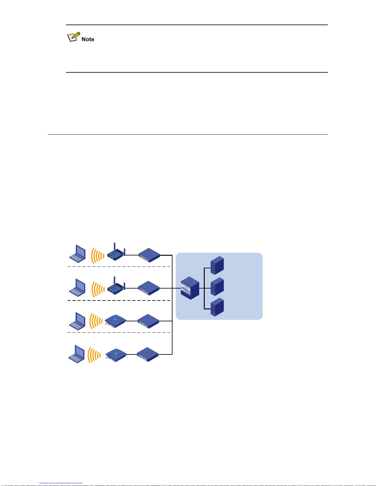
Figure 1-1 shows the typical deployment of the WA2200 series on hotspots.
Figure 1-1 Deployment of the WA2200 series on hotspots (Fat AP mode)
WA2200
WA2200
WA2200
WA2200
Core equipment
room
Radius server
Wireless
NMS
Service
database server
Switch
Switch
Switch
Switch
Switch
Auditorium
Restaurant or
tea house
Hall or information
desk
Parking lot
PC
PC
PC
PC
Figure 1-2 shows the appearance of the WA2200 series.

1-2
Figure 1-2 Appearance of the WA2200 series
Table 1-1 Physical dimensions of the WA2200 series
Model Physical dimensions (H×W×D) Weight
WA2210-AG/WA2220-AG, (indoor) 40×166×118 mm (1.57×6.54×4.65 in.) 0.5 kg (1.10 lb)
WA2210X-G/WA2220X-AG, (outdoor) 76×245×245 mm (2.99×9.65×9.65 in.) 2 kg (4.41 lb)
Hardware Configuration
The four models of the WA2200 series have different radio frequencies (RFs) and structures. Table 1-2
lists the protocols that each model supports as well as the chassis materials.
Table 1-2 Protocols that each model supports and the chassis material
Type Model Protocols and chassis material
Power
consumption
802.3af PoE
support
WA2210-AG
IEEE802.11a or IEEE802.11b/g,
plastic
8 W Yes
Indoor
WA2220-AG IEEE802.11a + IEEE802.11b/g, plastic 10 W Yes
WA2210X-G
IEEE802.11b/g, waterproof cast
aluminum + plastic
8 W Yes
Outdoor
WA2220X-AG
IEEE802.11a + IEEE802.11b/g,
waterproof cast aluminum + plastic
10 W No
An outdoor AP will start the internal over-cold protection function in case of a temperature lower than
–15°C, and the power consumption will increase 3 W to 5 W. In this case, you need to use an external
PoE module to supply power to the AP.
1-3
The WA2200 series have extraordinary radio frequency (RF) performance and provide consummate
service functions. With IP66 degree of protection, the outdoor models can be directly deployed outdoors
to simplify the installation. The models of the WA2200 series are designed for application in various
environments.
This section describes the hardware configurations and functions of the WA2200 series in detail.
LEDs
The positions and identifications of LEDs on the panel vary with the models. For details about these
LEDs, see
Table 1-3 and Table 1-4.
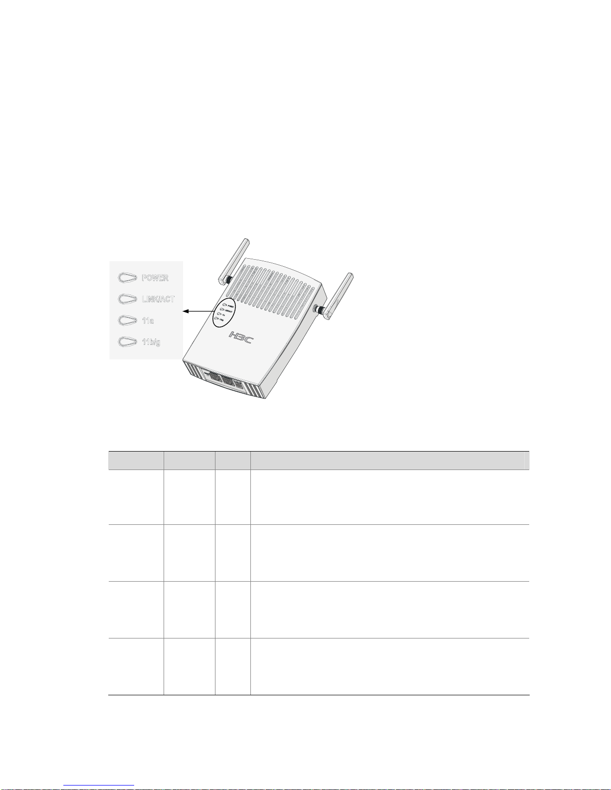
WA2210-AG/WA2220-AG
Figure 1-3 LEDs on the WA2210-AG/WA2220-AG
Table 1-3 Description of LEDs on the WA2210-AG/WA2220-AG
LED Color QTY Meaning
POWER Green
1
Displays the power supply status:
z On: The power supply is normal.
z Off/flashing: The power supply is not connected or well
connected, or works abnormally.
LINK/ACT Green
1
Displays the link status of the Ethernet interface:
z On: The link on the Ethernet interface is up.
z Off: The link on the Ethernet interface is down.
z Flashing: Data is being transmitted or received.
11a Green
1
Displays the wireless link status:
z Off: The wireless link is not initialized or the link is faulty.
z Flashing slowly: The wireless link is normal.
z Flashing quickly: Data is being transmitted or received.
11b/g
Green
1
Displays the wireless link status:
z Off: The wireless link is not initialized or the link is faulty.
z Flashing slowly: The wireless link is normal.
z Flashing quickly: Data is being transmitted or received.
1-4
The WA2210-AG is a single-RF device. The 11a and 11b/g LEDs cannot be on or flash at the same
time.
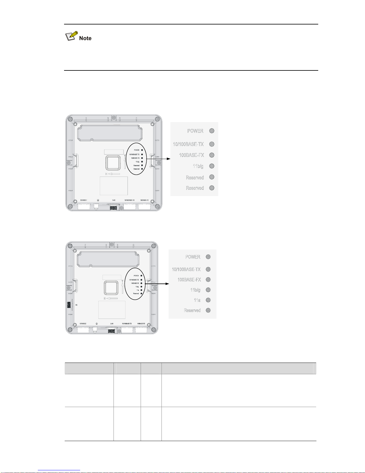
WA2210X-G/WA2220X-AG
Figure 1-4 LEDs on the WA2210X-G
Figure 1-5 LEDs on the WA2220X-AG
Table 1-4 Description of LEDs on the WA2210X-G/WA2220X-AG
LED Color QTY Meaning
POWER Green 1
Displays the power supply status:
z On: The power supply is normal..
z Off/flashing: The power supply is not connected or well
connected or the device works abnormally.
10/100BASE-TX Green 1
Displays the status of the Ethernet interface:
z On: The link on the Ethernet interface is up.
z Off: The link on the Ethernet interface is down.
z Flashing: Data is being transmitted or received.
1-5
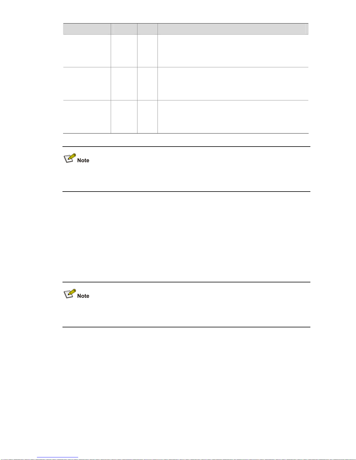
LED Color QTY Meaning
100BASE-FX
Yellow 1
Displays the status of the optical interface:
z On: The link on the optical interface is up.
z Off: The link on the optical interface is down.
z Flashing: Data is being transmitted or received.
11a Green 1
Displays the wireless link status:
z Off: The wireless link is not initialized or the link is faulty.
z Flashing slowly: The wireless link is normal.
z Flashing quickly: Data is being transmitted or received.
11b/g Green 1
Displays the wireless link status:
z Off: The wireless link is not initialized or the link is faulty.
z Flashing slowly: The wireless link is normal.
z Flashing quickly: Data is being transmitted or received.
z The WA2210X-G is a single-RF device and has no 11a LED.
z The word “reserved” means the LED is reserved for future use.
Interfaces
The interfaces provided by the WA2200 series include:
z 2.4 GHz or/and 5 GHz antenna interface(s)
z Console interface
z Ethernet interface (optical and electrical)
z Power interface for indoor models
In addition, a reset button (indoor and enhanced models), a security slot (indoor and enhanced models),
and a grounding screw (outdoor models) are provided.
Table 1-5 describes the interfaces provided by each model.

1-6
Table 1-5 Descriptions of interfaces on WA2200 series WLAN access points
Model Interface
Standards and
protocols
Description
Antenna
interface 1
IEEE802.11b/g
WA2210-AG: Main antenna interface,
2.4/5-GHz
WA2220-AG: 2.4-GHz antenna interface
Console
interface
RS/EIA-232
The console interface is used for device
configuration and management.
Ethernet
interface
IEEE802.3
IEEE802.3u
IEEE802.3af
The Ethernet interface can serve as an
uplink interface of the device to access the
Internet or a MAN, and can simultaneously
serve as a PoE interface.
Power interface N/A
The power interface is used for +48 VDC
power supply to the device.
WA2210-AG/
WA2220-AG
Antenna
interface 2
IEEE802.11a
WA2210-AG: Auxiliary antenna interface,
2.4/5-GHz
WA2220-AG: 5-GHz antenna interface
Ethernet optical
interface
IEEE802.3
SFP MSA
SFF-8472
The Ethernet optical interface can serve as
an uplink interface to access the Internet or
a MAN. The Ethernet optical interface is
used to connect an SFP module. In practice,
either the Ethernet electrical interface or the
Ethernet optical interface is used.
Ethernet
electrical
interface
IEEE802.3
IEEE802.3u
IEEE802.3af
The Ethernet electrical interface can serve
as an uplink interface of the device to
access the Internet or a MAN, and can
simultaneously serve as a PoE interface.
Antenna
interface 1
IEEE802.11b/g
This antenna interface is used to connect a
2.4-GHz antenna or a feeder.
Console
interface
RS/EIA-232
The console interface is used for device
configuration and management.
WA2210X-G/
WA2220X-AG
Antenna
interface 2
IEEE802.11a
This antenna interface is used to connect a
5-GHz antenna or a feeder.
1-7
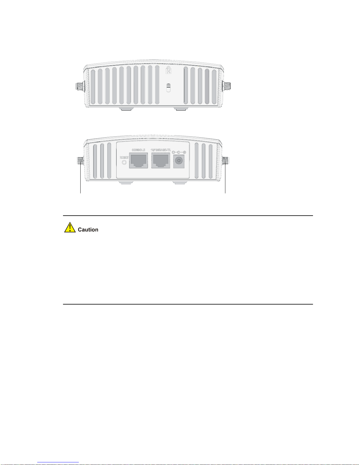
Interfaces provided by WA2210-AG/WA2220-AG
Figure 1-6 Interfaces on WA2210-AG/WA2220-AG
Top view
Bottom view
Antenna interface 1
Antenna interface 2
z WA2210-AG is a single-RF device. Viewed from the front, the antenna interface on the left
(antenna interface 1 in
Figure 1-6) is the main antenna interface, while the one on the right
(antenna interface 2 in
Figure 1-6) is the auxiliary antenna interface. When there is only one
antenna, the antenna must be installed on the main antenna interface.
z WA2220-AG is a dual-RF device. Viewed from the front, the antenna interface on the left (antenna
interface 1 in
Figure 1-6) is the 2.4-GHz antenna interface, while the one on the right (antenna
interface 2 in
Figure 1-6) is the 5-GHz antenna interface.
1-8
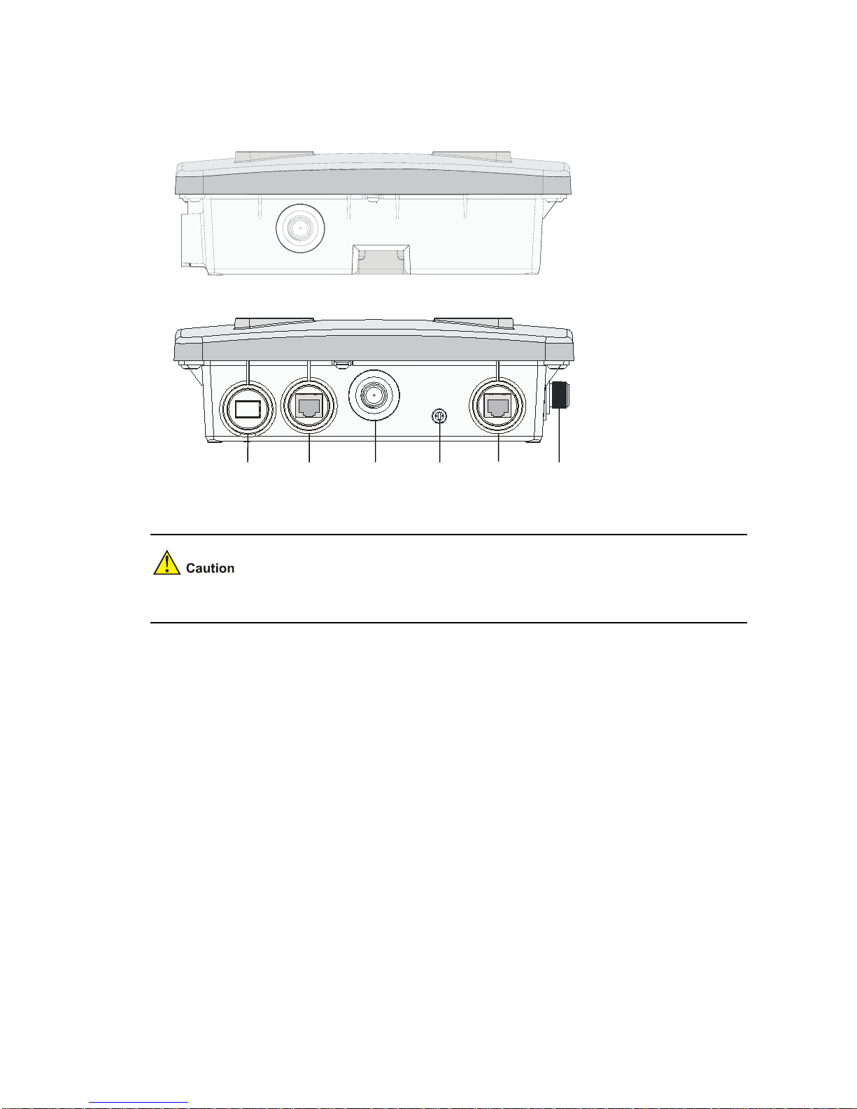
Interfaces provided by WA2210X-G/WA2220X-AG
Figure 1-7 Interfaces on WA2210X-G/WA2220X-AG
Right view(WA2220X-AG)
Bottom view(WA2210X-G/WA2220X-AG)
Consol
interface
Grounding
screw
Antenna
interface1
10/100BASE-TX
100BASE-FX
Antenna
interface2
WA2210X-G is a single-RF device and provides no 5-GHz antenna interface.
 Loading...