

Page 1

H3C WA2110-AG
Wireless LAN Access Point
Hangzhou H3C Technologies Co., Ltd.
http://www.h3c.com
Document version: T2-08226P-20110225-C-1.08
Quick Start
Page 2

Copyright © 2007-2011, Hangzhou H3C Technologies Co., Ltd. and its
licensors
All rights reserved
No part of this manual may be reproduced or transmitted in any form or
by any means without prior written consent of Hangzhou H3C
Technologies Co., Ltd.
Trademarks
H3C,
, Aolynk, , H3Care,
, TOP G, , IRF,
NetPilot, Neocean, NeoVTL, SecPro, SecPoint, SecEngine, SecPath,
Comware, Secware, Storware, NQA, VVG, V
2
G, VnG, PSPT, XGbus,
N-Bus, TiGem, InnoVision and HUASAN are trademarks of Hangzhou
H3C Technologies Co., Ltd.
All other trademarks that may be mentioned in this manual are the
property of their respective owners
Notice
The information in this document is subject to change without notice.
Every effort has been made in the preparation of this document to ensure
accuracy of the contents, but all statements, information, and
recommendations in this document do not constitute the warranty of any
kind, express or implied.
Environmental protection
This product has been designed to comply with the environmental
protection requirements. The storage, use, and disposal of this product
must meet the applicable national laws and regulations.
Page 3
Preface
The WA2110-AG Wireless LAN Access Point Quick Start describes the
technical specifications, installation and safety precaution.
This preface includes:
• Audience
• Conventions
• About the H3C WA2110-AG documentation set
• Obtaining documentation
• Technical support
• Documentation feedback
Audience
This documentation is intended for:
• Network planners
• Field technical support and servicing engineers
• Network administrators working with the WA2110 -AG
Conventions
This section describes the conventions used in this documentation set.
Symbols
Convention Description
WARNING
CAUTION
NOTE
An alert that calls attention to important information that if
not understood or followed can result in personal injury.
An alert that calls attention to important information that if
not understood or followed can result in data loss, data
corruption, or damage to hardware or software.
An alert that contains additional or supplementary
information.
Page 4

About the H3C WA2110-AG documentation set
The H3C WA2110-AG documentation set includes:
Category Documents Purposes
Product
description and
specifications
Hardware
specifications
and installation
Software
configuration
Operations and
maintenance
Marketing brochures
Technology white
papers
Quick start
Configuration
examples
Release notes
Describe product specifications
and benefits.
Provide an in-depth description of
software features and
technologies.
Guides you through initial
installation and setup procedures to
help you quickly set up and use
your device with the minimum
configuration.
Provides regulatory information
and the safety instructions that must
be followed during installation
Describe typical network scenarios
and provide configuration
examples and instructions.
Provide information about the
product release, including the
version history, hardware and
software compatibility matrix,
version upgrade information,
technical support information, and
software upgrading.
Obtaining documentation
You can access the most up-to-date H3C product documentation on the
World Wide Web at
Click the links on the top navigation bar to obtain different categories of
product documentation:
http://www.h3c.com.
Page 5

[Technical Support & Documents > Technical Documents] – Provides
hardware installation, software upgrading, and software feature
configuration and maintenance documentation.
[Products & Solutions] – Provides information about products and
technologies, as well as solutions.
[Technical Support & Documents > Software Download] – Provides the
documentation released with the software version.
Technical support
customer_service@h3c.com
http://www.h3c.com
Documentation feedback
You can e-mail your comments about product documentation to
info@h3c.com.
We appreciate your comments.
Page 6

Contents
Product Overview·····························································································1
Introduction to H3C WA2110-AG ································································1
Technical Specifications ··················································································1
Installation·········································································································3
Safety Precautions···························································································· 3
Product Appearance························································································ 4
Installation Procedure ······················································································6
Preparing Installation Tools ····································································7
Checking the Device Before Installation ···············································7
Attaching the Antennas··········································································· 7
Mounting the Access Point ····································································· 7
Connecting the Access Point to an Access Controller/Unified Switch·····11
Appendix A Safety Information Sicherheits informationen安全信息········ 12
Conventions Used Symbole Erläuterung应用惯例 ·····························12
Important Safety Information/Wichtige Sicherheitshinweise/重要安全
信息 ········································································································
Electricity Safety Elektrische Sicherheit 用电安全 ······························14
Appendix B Regulatory Compliance Information·······································15
Regulatory compliance standards ································································15
Support Antennas & Accessories information·············································16
EU Compliance information··········································································16
CE Marking····························································································16
EU Country Restriction in 2.4GHz band ············································19
EU Country Restriction in 5GHz band ················································19
WEEE Directive–2002/96/EC ···························································21
USA regulatory compliance··········································································21
FCC Part 15···························································································21
Canada regulatory compliance····································································22
ICES-003 ································································································22
RF Compliance ······················································································22
Brazil RF Compliance ····················································································23
Korea RF Compliance····················································································23
Taiwan regulatory statement·········································································24
13
Index··············································································································· 25
i
Page 7

g
Product Overview
Introduction to H3C WA2110-AG
Developed by Hangzhou H3C Technologies Co., Ltd. independently, the
H3C WA2110-AG is a managed wireless LAN access point device. It is
designed for use with a H3C WX series access controller/unified switch,
and requires only hardware installation. All configurations for the access
point take place on the access controller/unified switch.
Technical Specifications
The WA2110-AG can be powered through 802.3af-compliant power
over Ethernet (PoE). The following table lists the technical specifications of
the WA2110- AG.
Table 1 Technical specifications
Index Value
Maximum power consumption 6 W
Ethernet interface standard 802.3af
Wireless interface standard 802.11a, and 802.11b/g
Operating temperature -10°C to 55°C (14°F to 131°F)
Operating humidity (noncondensing) 5% to 95%
NOTE:
• The WA2110-AG also can be powered through an external power
adaptor. For details see the
• The power adapter is not shipped with the device. You may purchase
it separately. For details, contact our local agents.
• Outside China it is recommended that this unit be PoE powered.
Please see the H3C/3Com product catalo
compatible power sources.
Table 2.
ues for a range of 802.3af
1
Page 8
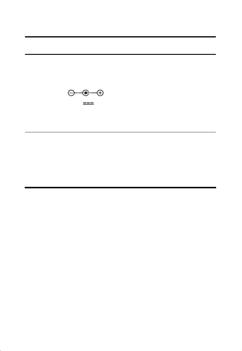
Table 2 Descriptions of power source
Power
Source
AC / DC
Power
Adapter
Power over
Ethernet (PoE,
IEEE 802.3af
standard)
power source
Connection Details Ordering information
The WA2110-AG access point can
accept power from an AC / DC
power adapter. Input specification is
as follows:
+48V
Connect the adapter’s power jack to
the WA2110-AG power interface
Figure 1 (3)
The WA2110-AG access point can
accept power from a PoE power
source.
No DC power adapter is required.
Connect the PoE cable directly to the
10/100 Base-TX Ethernet connector
Figure 1 (4)
, 0.52A min.
If you need an AC / DC
power adapter for your
WA2110-AG access
point, you must use the
FSP025-1AD207A
adapter (part number
0231A0EQ)which is
available from H3C /
3Com.
Please see the H3C /
3Com product
catalogues for a range of
802.3af compatible
power sources.
2
Page 9
t
Installation
This chapter contains the following contents:
• Safety precautions
• Product appearance
• Installation procedure
• Connecting the access point to an access controller/unified switch
Safety Precautions
WARNING!
Installation and removal of the unit and its accessories must be carried ou
by qualified personnel. You must read all of the Safety Instructions
supplied with your device before installation and operation.
WARNUNG!
Installation und Ausbau der Anlage und ihrer Zubehörteile müssen von
qualifiziertem Personal realisiert werden. Sie müssen vor der Installation
oder Bedienung allen beiliegenden Sicherheitshinweise lesen.
警告
负责安装和日常维护本设备的人员必须具备安全操作基本技能。在操
作本设备前,请务必认真阅读和执行产品手册规定的安全规范。
A WA2110-AG must be installed in compliance with related safety
standards and specifications. For the safety of personnel and equipment,
only professional network personnel should install the device.
3
Page 10
g
g
t
CAUTION:
• To ensure that the access point complies with the related authentication
domain regulations, configure the country code by executing the wlan
country-code command on the access controller/unified switch before
the access point begins to operate. For details about the wlan
country-code command, refer to the WLAN Configuration
Commands of the WLAN Command Reference in H3C WX Series
Access Controllers Command References.
• Check that the volta
powerin
on the device, and be sure to use power supply devices tha
e range is compliant to the requirements before
are in compliance with the related safety standards.
WARNING!
Do not use or manipulate your WA2110-AG near any uncovered
exploders or in any other explosive environments, unless otherwise
authorized by related functionaries.
Product Appearance
The following figure shows the appearance of a WA2110- AG.
4
Page 11

Figure 1 Appearance of a WA2110-AG
(1) LED (2) Antenna connector
(3) Power interface (4) 10/100 Base-TX Ethernet interface
(5) Console port (6) Mounting bracket
The following figure shows the LEDs of the device.
Figure 2 LEDs of a WA2110-AG
(1) POWER: Power LED (2) 11a: 802.11a LED
(3) 11b/g: 802.11b/g LED (4) LINK: Ethernet status LED
The following table describes the meanings of the LEDs.
5
Page 12

Table 3 Meanings of the LEDs
LED Meaning
Indicates the working status of the power supply:
POWER
11a
11b/g
On: The device is working properly.
Off: The device is not powered on or is faulty.
Indicates the status of the wireless link when the device works in the
11a mode:
Off: The wireless link is not initialized or is faulty.
Blinking slowly: A small amount of data is being transmitted or
received through the wireless link.
Blinking quickly: A large amount of data is being transmitted or
received through the wireless link.
Indicates the status of the wireless link when the device works in the
11b/g mode:
Off: The wireless link is not initialized or is faulty.
Blinking slowly: A small amount of data is being transmitted or
received through the wireless link.
Blinking quickly: A large amount of data is being transmitted or
received through the wireless link.
Indicates the working status of the Ethernet port:
On: A link is present.
LINK
Off: No link is present.
Blinking: Data is being transmitted or received through the Ethernet
port.
Installation Procedure
This section covers the following contents:
• Preparing installation tools
• Checking the device before installation
• Attaching the antennas
• Mounting the access point
6
Page 13

g
g
Preparing Installation Tools
Prepare the following tools before installation:
• Mounting bracket and screws that come with the device
• Electric screwdriver and Phillips screwdriver
• One electric drill and several auxiliary drill bits
Checking the Device Before Installation
Before mounting the WA2110-AG, connect it to the power adapter (if
applicable) and the Ethernet, and check the status of the LEDs to ensure
that the WA2110-AG can work properly. In addition, record the MAC
address of the access point for future use.
Attaching the Antennas
Attach the antennas accompanying the access point on to the antenna
connectors on the access point and hand-tighten them. After network
startup, you may need to adjust the antennas to fine-tune the coverage in
your area. For best results, adjust the antennas so that they are
perpendicular with the floor or ceiling.
CAUTION:
Do not handle the antenna tips, especially after they are connected to the
access point. This could lead to electrostatic dischar
damage the equipment.
WARNING!
Do not touch or remove the access point when its antenna is receivin
transmitting radio frequency signals.
e (ESD), which could
Mounting the Access Point
The access point can be mounted on walls, ceilings, or tabletops.
Wall, ceiling mounting
To mount the access point to a wall or ceiling, follow these steps:
7
or
Page 14

g
g
1.
Remove the access point from the mounting bracket.
2. Route the Ethernet cable and, if you are using a power adapter, the
power cable on the back of the mounting bracket, as shown in
CAUTION:
• For easy installation and removal of the access point from the
Figure 3.
mounting bracket, make sure that there is sufficient flexibility with the
cable and that the cable is lon
throu
h the back of the mounting bracket, or the cable is inflexible, it
enough. If not enough cable is routed
can be difficult to install or remove the access point from the mounting
bracket.
• It is recommended to use flexible cables.
Figure 3 Cabling on the back of the bracket
3. Mount the bracket to a wall or ceiling, as shown in Figure 4.
8
Page 15

Figure 4 Mount the bracket (unit: mm)
70.00
4.50
6.00
78.80
4. Connect the Ethernet cable and, if you are using a power adapter, the
power cable to the corresponding port(s) on the access point.
9
Page 16

g
g
t
CAUTION:
• To avoid connection interference caused by dust, clean the pins of the
cable connector before connecting the cable to the access point.
• Discharge the cable before connecting it to the access point.
WARNING!
• In the case of lightning, do not plug/unplug the cable to/from the
access point.
• When the LEDs of the access point are blinkin
, do not plug/unplug
the cable to/from the access point or perform any operation that may
affect the normal running of the access point.
5. Align the bottom of the access point with the mounting bracket, and
press the access point backward. Thus, the access point is mounted in
the mounting bracket properly.
WARNING!
To avoid physical dama
e to the access point, do not mount or dismoun
the access point with excessive force.
6. To prevent the access point from being stolen, insert the locking bar (as
shown in (1) of
Figure 5) into the opening at one side of the mounting
bracket. Push the locking bar through the opening until the hole on the
locking bar is exposed. Insert the shackle of a lock through the hole on
the locking bar to lock the access point with the mounting bracket, as
shown in (2) of
Figure 5.
Figure 5 Lock the access point with the mounting bracket
10
Page 17

Tabletop mounting
To install the access point on a flat surface such as a table or desktop,
follow these steps:
1. Remove the access point from the mounting bracket.
WARNING!
When the RF antennas are transmitting data, keep the antennas away
from your face, eyes, and other exposed part of your body.
2. Place the access point on the table.
WARNING!
• Do not mount the access point on any metal surface. Place it at a
position with good signal coverage.
• Do not use or manipulate the access point near any uncovered
exploders or in any other explosive environments, unless otherwise
3. Connect the Ethernet cable and, if you are using a power adapter, the
authorized by related functionaries.
power cable to the corresponding port(s) on the access point.
Connecting the Access Point to an Access Controller/Unified Switch
You can connect the access point to an access controller/unified switch
directly, or indirectly through an intermediate Layer 2 or Layer 3 network.
In either case, use a Category 5e cable for the connection.
You are recommended to install and configure the access
controller/unified switch before installing the access point. This is to
ensure that you can verify whether the access point works normally
immediately after you connect it. For instructions on configuring the
access controller or unified switch. refer to H3C WX Series Access
Controllers Configuration Guides, H3C WX Series Access Controllers
Command References and H3C WX Series Access Controllers
Web-Based Configuration Guide.
11
Page 18

Appendix A Safety Information Sicherheits informationen 安全信息
Conventions Used Symbole Erläuterung 应用惯 例
The symbols in this manual are shown in the following table. They are
used to remind the reader of the safety precautions during equipment
installation and maintenance.
Die Symbole in diesem Handbuch verwendeten sind in der folgenden
Tabelle dargestellt. Diese Symbole sollen das Personal während der
Installation und Instandhaltung der Ausrüstung an die Wichtigkeit der im
Handbuch aufgeführten Sicherheitsvorschriften erinnern.
以下表格中的安全标识,是用来提示读者在进行设备安装和维护时的安
全预防要求。
Table 4 Safety symbol and description
Sicherheitssymbole und Beschreibung 安全标识和描述
Safety
Symbol
Symbole
安全标识
Description
Erläuterung
描述
Generic alarm symbol: To suggest a general safety concern
Alarm: Hinweis auf ein generelles Sicherheitsproblem
一般注意标识:用于一般安全提示
ESD protection symbol: To suggest electrostatic-sensitive
equipment.
ESD-Schutz: Hinweis auf Beschädigung infolge elektrostatischer
Entladung
防静电标识:用于表示静电敏感的设备
12
Page 19

Safety
Symbol
Symbole
安全标识
Description
Erläuterung
描述
Electric shock symbol: To suggest a danger of high voltage
Elektrischer Schlag: Hinweis auf Gefährdung durch
Hochspannung
电击防护标识:用于表示高压危险
Important Safety Information/Wichtige Sicherheitshinweise/重要安全信息
Caution: You must read all of the installation instructions in the
Installation Guide supplied with your equipment and the
following safety instructions before installation or operation.
Achtung: Sie müssen vor der Installation oder Bedienung das mit
Ihrer Anlage mitgelieferten Installationshandbuch und die
folgende Sicherheitshinweise lesen.
注意:在安装和操作本设备时,务必阅读设备安装手册的内容,
以及下文的所有安全说明。
Caution: Do not block ventilation openings while the system is on,
and keep at least 5 cm distance from ventilation openings and
walls or other things which may block the openings.
Achtung: Blockieren Sie die Lüftungsmündungen nicht, wenn das
System läuft. Stellen Sie die Lüftungsmündungen mindestens 5 cm
entfernt von der Wände oder anderen Sachen, die die
Mündungen blockieren können.
注意:设备在工作时必须确保通风口的畅通,确保设备离墙壁或
是其它的可能堵塞通风口的物体的间距至少
WARNING: Before the power cable is installed or removed, the
power switch must be turned off.
Warnung: Das System muss stets abgeschaltet werden, bevor die
Zuleitung angebracht oder entfernt wird.
警告:在安装、移动线缆之前,请切断电源。
13
5cm。
Page 20

WARNING: Before the power cable is connected, it must be
confirmed that the power cable and label comply with the
requirements of the actual installation.
Warnung: Überprüfen Sie vor dem Anbringen der Zuleitung
immer, ob das von Ihnen verwendete Kabel den Anforderungen
entspricht.
警告:在进行线缆连接前,请确认线缆和线缆的标识与实际安装
要求是一致的。
WARNING: To ensure the equipment mounted on the wall firmly,
please use nail at least 4.2 mm diameter and the nail cap at least
8 mm diameter.
Warnung: Um die Sicherheit der Ausrüstung auf der Wand, der
Nagel in der Wand muss einen Durchmesser 4.2 mm
mindestens haben und der Durchmesser von der Nagelkappe
muss groesser als 8 mm sein.
警告:为确保设备紧固的安装在墙上,请用直径最小是
钉子,并且钉子帽的直径要大于
4.2mm
8mm。
Electricity Safety Elektrische Sicherheit 用电安全
• Conducting articles, such as watch, hand chain, bracelet and ring are
prohibited during the operation.
• Es ist nicht erlaubt während dieser Arbeiten leitende Gegenstände wie
Uhren, Armbänder, Armreifen und Ringe am Körper zu tragen.
• 在操作中不能穿戴导电性的物品,如:手表,手琏,手镯和项链等。
• When water is found in the rack, or the rack is damp, please immediately
switch off the power supply.
• Sollte sich Wasser im Baugruppenträger befinden oder der
Baugruppenträger feucht sein, ist die Energiezufuhr sofort zu
unterbrechen und das System abzuschalten.
• 当有液体进入机架或机架有损坏时,请立即切断电源。
14
Page 21

Appendix B Regulatory Compliance Information
Regulatory compliance standards
Table 5 Regulatory compliance standards
Discipline Standards
FCC Part 15 (CFR 47) Subpart B section 15.107&15.109
Class B
ICES-003 Class B
EMC
Safety
EN 61000-3-2
EN 61000-3-3
EN 301 489-1
EN 301 489-17
UL 60950-1
CAN/CSA C22.2 No 60950-1
IEC 60950-1
EN 60950-1
AS/NZS 60950-1
FCC Part 15 subpart C section 15.207 & 15.209 &
15.247& 15.205; subpart D section 15.407
RF
FCC Bulletin OET-65C
RSS-210
EN 300 328
EN 301 893
15
Page 22

Support Antennas & Accessories information
This product can be used with the following antennas and accessories:
Table 6 Authorized Antennas & Accessories
Item Description Exclusions
W1450 2/3dBi Dual-Band Omni Antenna None
• This product does not contain any user serviceable components. Any
unauthorized product changes or modifications will invalidate the
warranty and all applicable regulatory certifications and approvals.
• This product must be installed by a professional technician/ installer.
EU Compliance information
CE Marking
Table 7 Equipment may be operated in the following country:
AT BE CY CZ DK EE FI FR
DE GR HU IE IT LV LT LU
MT NL PL PT SK SI ES SE
GB IS LI NO CH BG RO TR
1. Select the country in which the product is installed to ensure product
operation is in compliance with local regulations. For information on
how to select the country, refer to the WLAN Configuration Commands
of the WLAN Command Reference in H3C WX Series Access
Controllers Command References.
2. Intended use: IEEE 802.11 a/b/g radio LAN device.
16
Page 23

3.
This product must maintain a minimum body to antenna distance of
20cm.Under these conditions this product will meet the Basic Restriction
limits of 1999/519/EC(Council Recommendation of 12 July 1999 on
the limitation of exposure of the general public to electromagnetic
fields(0Hz-300GHz)).
Table 8 R&TTE declaration statements:
Česky
[Czech]
Dansk
[Danish]
Deutsch
[German]
Eesti
[Estonian]
English
Español
[Spanish]
Ελληνική
[Greek]
H3C Coporation tímto prohlašuje, že tento RLAN je ve shodě se
základními požadavky a dalšími příslušnými ustanoveními
směrnice 1999/5/ES.
Undertegnede H3C Corporation erklærer herved, at følgende
udstyr RLAN overholder de væsentlige krav og øvrige relevante
krav i direktiv 1999/5/EF.
Hiermit erklärt H3C Corporation, dass sich das Gerät RLAN in
Übereinstimmung mit den grundlegenden Anforderungen und
den übrigen einschlägigen Bestimmungen der Richtlinie
1999/5/EG befindet.
Käesolevaga kinnitab H3C Corporation seadme RLAN vastavust
direktiivi 1999/5/EÜ põhinõuetele ja nimetatud direktiivist
tulenevatele teistele asjakohastele sätetele.
Hereby, H3C Corporation, declares that this RLAN is in
compliance with the essential requirements and other relevant
provisions of Directive 1999/5/EC.
Por medio de la presente H3C Corporation declara que el RLAN
cumple con los requisitos esenciales y cualesquiera otras
disposiciones aplicables o exigibles de la Directiva 1999/5/CE.
ΜΕ ΤΗΝ ΠΑΡΟΥΣΑ H3C Corporation ΔΗΛΩΝΕΙ ΟΤΙ RLAN
ΣΥΜΜΟΡΦΩΝΕΤΑΙ ΠΡΟΣ ΤΙΣ ΟΥΣΙΩΔΕΙΣ ΑΠΑΙΤΗΣΕΙΣ ΚΑΙ ΤΙΣ
ΛΟΙΠΕΣ ΣΧΕΤΙΚΕΣ ΔΙΑΤΑΞΕΙΣ ΤΗΣ ΟΔΗΓΙΑΣ 1999/5/ΕΚ.
Français
[French]
Italiano
[Italian]
Par la présente H3C Corporation déclare que l'appareil RLAN est
conforme aux exigences essentielles et aux autres dispositions
pertinentes de la directive 1999/5/CE.
Con la presente H3C Corporation dichiara che questo RLAN è
conforme ai requisiti essenziali ed alle altre disposizioni pertinenti
stabilite dalla direttiva 1999/5/CE.
17
Page 24

Latviski
[Latvian]
Lietuvių
[Lithuanian]
Nederlands
[Dutch]
Malti
[Maltese]
Magyar
[Hungarian]
Polski [Polish]
Português
[Portuguese]
Slovensko
[Slovenian]
Ar šo H3C Corporation deklarē, ka RLAN atbilst Direktīvas
1999/5/EK būtiskajām prasībām un citiem ar to saistītajiem
noteikumiem.
Šiuo H3C Corporation deklaruoja, kad šis RLAN atitinka esminius
reikalavimus ir kitas 1999/5/EB Direktyvos nuostatas.
Hierbij verklaart H3C Corporation dat het toestel RLAN in
overeenstemming is met de essentiële eisen en de andere
relevante bepalingen van richtlijn 1999/5/EG.
Hawnhekk, H3C Corporation, jiddikjara li dan RLAN jikkonforma
mal-ħtiġijiet essenzjali u ma provvedimenti oħrajn relevanti li
hemm fid-Dirrettiva 1999/5/EC.
Alulírott, H3C Corporation nyilatkozom, hogy a RLAN megfelel a
vonatkozó alapvetõ követelményeknek és az 1999/5/EC
irányelv egyéb elõírásainak.
Niniejszym H3C Corporation oświadcza, że RLAN jest zgodny z
zasadniczymi wymogami oraz pozostałymi stosownymi
postanowieniami Dyrektywy 1999/5/EC.
H3C Corporation declara que este RLAN está conforme com os
requisitos essenciais e outras disposições da Directiva
1999/5/CE.
H3C Corporation izjavlja, da je ta RLAN v skladu z bistvenimi
zahtevami in ostalimi relevantnimi določili direktive 1999/5/ES.
Slovensky
[Slovak]
Suomi
[Finnish]
Svenska
[Swedish]
H3C Corporation týmto vyhlasuje, že RLAN spĺňa základné
požiadavky a všetky príslušné ustanovenia Smernice
1999/5/ES.
H3C Corporation vakuuttaa täten että RLAN tyyppinen laite on
direktiivin 1999/5/EY oleellisten vaatimusten ja sitä koskevien
direktiivin muiden ehtojen mukainen.
Härmed intygar H3C Corporation att denna RLAN står I
överensstämmelse med de väsentliga egenskapskrav och övriga
relevanta bestämmelser som framgår av direktiv 1999/5/EG.
18
Page 25

Íslenska
[Icelandic]
Norsk
[Norwegian]
Hér með lýsir H3C Corporation yfir því að RLAN er í samræmi við
grunnkröfur og aðrar kröfur, sem gerðar eru í tilskipun
1999/5/EC.
H3C Corporation erklærer herved at utstyret RLAN er i samsvar
med de grunnleggende krav og øvrige relevante krav i direktiv
1999/5/EF.
A copy of the signed Declaration of Conformity can be downloaded
from:
• http://www.h3c.com/portal/Technical_Documents or
• http://www.hp.eu/certificates
Table 9 Overview of Regulatory Requirements for Wireless LANs
Frequency Band (MHz)
2400–2483.5 100 mW X
5150–5350 200 mW X
5470–5725 1000 mW X
Max Power
Level
(EIRP) (mW)
Indoor ONLY
Indoor and
Outdoor
Dynamic Frequency Selection and Transmit Power Control are required in
the 5250- to 5350-MHz and 5470- to 5725-MHz frequency range.
EU Country Restriction in 2.4GHz band
The products may be used indoors or outdoors in all countries of the
European Community using the 2.4GHz band: Channel 1-13, except
where noted below.
In France, the output power is restricted to 10 mW EIRP when the product
is used outdoors in the band 2454 - 2483.5MHz. There are no
restrictions when used in other parts of the 2.4 GHz band.
EU Country Restriction in 5GHz band
1. In Italy the end-user must apply for a license from the national spectrum
authority to operate this device outdoors.
19
Page 26

2.
To remain in conformance with European spectrum usage laws for
Wireless LAN operation, the above 2.4GHz and 5GHz channel
limitations apply. The user should check the current channel of operation.
If operation is occurring outside of the allowable frequencies as listed
above, the user must cease operating the product at that location and
consult the local technical support staff responsible for the wireless
network.
3. This device must be used with the radar detection feature required for
European Community operation in the 5GHz bands. This device will
avoid operating on a channel occupied by any radar system in the area.
The presence of nearby radar operation may result in temporary
interruption in communications of this device. The Access Point’s radar
detection feature will automatically restart operation on a channel free
of radar. You may consult with the local technical support staff
responsible for the wireless network to ensure the Access Point device(s)
are properly configured for European Community operation.
Table 10 Europe-Restrictions for Use of 5GHz Frequencies in European
Community Countries
Allowed Frequency
Bands
5.15-5.35&
5.470-5.725GHz
Allowed Channel
Numbers
36,40,44,48,52,56,60
,64,100,104,108,112,
116,120,124,128,132
,136,140
20
Countries
Austria, Belgium, Bulgaria,
Cyprus, Czech Republic,
Denmark, Estonia, Finland,
France, Germany, Greece,
Hungary, Iceland, Ireland,
Italy, Latvia, Liechtenstein,
Lithuania, Luxembourg,
Malta, Netherlands,
Norway, Poland, Portugal,
Slovakia, Slovenia, Spain,
Sweden, Switzerland, U.K.
Page 27

WEEE Directive–2002/96/EC
The products this manual refers to are covered by the Waste Electrical &
Electronic Equipment (WEEE) Directive and must be disposed of in a
responsible manner.
USA regulatory compliance
FCC Part 15
US Federal Communications Commission (FCC) EMC Compliance
The product complies with Part 15 of the FCC Rules. Operation is subject
to the following two conditions:
1. This device may not cause harmful interference.
2. This device must accept any interference received, including
interference that may cause undesired operation.
RF Requirements
1. RF exposure Hazard Warning
This device generates and radiates radio-frequency energy. In order to
comply with FCC radio-frequency exposure guidelines for an
uncontrolled environment, this equipment must be installed and operated
while maintaining a minimum body to antenna distance of 20 cm
(approximately 8 in.)
2. RF Frequency Requirements
This equipment complies with FCC RF radiation exposure limits set forth
for an uncontrolled environment. This device and its antenna must not be
co-located or operating in conjunction with any other unauthorized
antenna or transmitter.
21
Page 28

This device is for indoor use only when using channels 36, 38, 40, 44,
46 or 48 in the 5.15 to 5.25 GHz frequency range.
High power radars are allocated as primary users of the 5.25 to 5.35
GHz and 5.65 to 5.85 GHz bands. These radar stations can cause
interference with and/or damage this device.
Antennas
Only use the supplied antenna. Unauthorized antennas, modifications or
change to the antennas could violate FCC regulations and void the user’s
authority to operate the equipment.
Canada regulatory compliance
ICES-003
This Class B digital apparatus complies with Canadian ICES-003.
Cet appareil numérique de la classe B est conforme à la norme
NMB-003 du Canada.
RF Compliance
This device complies with RSS 210 of Industry Canada.
Operation is subject to the following two conditions: (1) this device may
not cause interference, and (2) this device must accept any interference,
including interference that may cause undesired operation of this device.
L ‘ utilisation de ce dispositif est autorisée seulement aux conditions
suivantes: (1) il ne doit pas produire de brouillage et (2) l’ utilisateur du
dispositif doit étre prêt à accepter tout brouillage radioélectrique reçu,
même si ce brouillage est susceptible de compromettre le fonctionnement
du dispositif.
The term "IC" before the equipment certification number only signifies
that the Industry Canada technical specifications were met.
To reduce potential radio interference to other users, the antenna type
and its gain should be so chosen that the equivalent isotropically
radiated power (EIRP) is not more than that required for successful
22
Page 29

communication. To prevent radio interference to the licensed service, this
device is intended to be operated indoors and away from windows to
provide maximum shielding. Equipment (or its transmit antenna) that is
installed outdoors is subject to licensing.
Pour empecher que cet appareil cause du brouillage au service faisant
l'objet d'une licence, il doit etre utilize a l'interieur et devrait etre place
loin des fenetres afin de Fournier un ecram de blindage maximal. Si le
matriel (ou son antenne d'emission) est installe a l'exterieur, il doit faire
l'objet d'une licence.
High power radars are allocated as primary users of the 5.25 to 5.35
GHz and 5.65 to 5.85 GHz bands. These radar stations can cause
interference with and/or damage this device.
This device must not be co-located or operated in conjunction with any
other unauthorized antenna or transmitter.
Brazil RF Compliance
Este produto está homologado pela ANATEL, de acordo com os
procedimentos regulamentados pela Resolução 242/2000 e atende
aos requisitos técnicos aplicados.
Este equipamento opera em caráter secundário, isto é, não tem direito a
proteção contra interferência prejudicial, mesmo de estações do mesmo
tipo, e não pode causar interferência a sistemas operando em caráter
primário.
Para maiores informações, consulte o site da ANATEL –
www.anatel.gov.br
Korea RF Compliance
This device may cause radio interference during its operation. Therefore
service in relation to human life security is not available.
23
Page 30

Taiwan regulatory statement
1. 經型式認證合格之低功率射頻電機,非經許可,公司、商號或使用者
均不得擅自變更頻率、加大功率或變更原設計之特性及功能。
2. 射頻電信終端設備之使用不得影響飛航安全及干擾合法通信;經發現
有干擾現象時,應立即停用,並改善至無干擾時方得繼續使用。所謂
合法通信,係指依電信法規定作業之無線電信。低功率射頻電機須忍
受合法通信或工業、科學及醫療用電波輻射性電機設備之干擾。
3. 輸入、製造射頻電信終端設備之公司、商號或其使用者違反本辦法規
定,擅自使用或變更無線電頻率、電功率者,除依電信法規定處罰
外,電信總局並得撤銷其審驗合格證明。
4. 本機限在不干擾合法電台與不受被干擾保障條件下於室內使用。
5. 在 5.25-5.35 秭赫頻帶內操作之無線資訊傳輸設備,限於室內使用。
6. 無線資訊傳輸設備的製造廠商應確保頻率穩定性,如依製造廠商使用
手冊上所述正常操作,發射的信號應維持於操作頻帶中。
7. 為減少電磁波干擾,請妥適使用。
24
Page 31

Index
B
Brazil RF Compliance
C
Canada regulatory compliance
22
Connecting the Access Point to an
Access Controller/Unified Switch
11
E
EU Compliance information
I
Installation Procedure
Introduction to H3C WA2110- AG
1
K
Korea RF Compliance
P
23
16
6
23
Taiwan regulatory statement
Technical Specifications
U
USA regulatory compliance
1
24
21
Product Appearance
R
Regulatory compliance standards
15
S
Safety Precautions
Support Antennas & Accessories
information
T
16
4
3
25
 Loading...