

Page 1

H3C VG Series Voice Gateways
Web-based Configuration Manual
Hangzhou Huawei-3Com Technology Co., Ltd.
http://www.huawei-3com.com
Manual Version: T2-08014H-20060707-C-1.01
Page 2

Copyright © 2006, Hangzhou Huawei-3Com Technology Co., Ltd. and its licensors
All Rights Reserved
No part of this manual may be reproduced or transmitted in any form or by any means
without prior written consent of Hangzhou Huawei-3Com Technology Co., Ltd.
Trademarks
H3C, Aolynk, , IRF, H3Care,
, Neocean, , TOP G, SecEngine,
SecPath, COMWARE, VVG, V
2
G, VnG, PSPT, NetPilot, and XGbus are trademarks of
Hangzhou Huawei-3Com Technology Co., Ltd.
All other trademarks that may be mentioned in this manual are the property of their
respective owners.
Notice
The information in this document is subject to change without notice. Every effort has
been made in the preparation of this document to ensure accuracy of the content s, but
all statements, information, and recommendations in this document do not constitute
the warranty of any kind, express or implied.
To obtain the latest information, please access:
http://www.huawei-3com.com
Technical Support
customer_service@huawei-3com.com
http://www.huawei-3com.com
Page 3

About This Manual
Related Documentation
In addition to this manual, each H3C VG Series Voice Gateways documentation set
includes the following:
Manual Description
H3C VG Series Voice Gateways
Operation Manual
It provides guidelines to user operations on
the H3C VG Series Voice Gateways.
H3C VG Series Voice Gateways
Command Manual
It provides all commands available in the
H3C VG Series Voice Gateways as well as
the command usage and examples.
H3C VG Series Voice Gateways
Installation Manual
It describes how to install a VG and provides
safety recommendations as well.
Organization
H3C VG Series Voice Gateways Web-based Configuration Manual is organized as
follows:
Chapter Contents
1 Introduction to VG Briefly introduces the usage and
features of the VG series voice
gateways.
2 Getting Started with Configuration Introduces the connection, login and
configuration GUIs of voice gateways.
3 Web Configuration of VG Describes how to perform configurations
through the voice gateway Web pages in
detail.
Conventions
The manual uses the following conventions:
I. Command conventions
Convention Description
Boldface
The keywords of a command line are in Boldface.
Page 4
Convention Description
italic
Command arguments are in italic.
[ ]
Items (keywords or arguments) in square brackets [ ] are
optional.
{ x | y | ... }
Alternative items are grouped in braces and separated by
vertical bars. One is selected.
[ x | y | ... ]
Optional alternative items are grouped in square brackets
and separated by vertical bars. One or none is selected.
{ x | y | ... } *
Alternative items are grouped in braces and separated by
vertical bars. A minimum of one or a maximum of all can be
selected.
[ x | y | ... ] *
Optional alternative items are grouped in square brackets
and separated by vertical bars. Many or none can be
selected.
# A line starting with the # sign is comment s.
II. GUI conventions
Convention Description
< >
Button names are inside angle brackets. For example, click
<OK>.
[ ]
Window names, menu items, data table and field names
are inside square brackets. For example, pop up the [New
User] window.
/
Multi-level menus are separated by forward slashes. For
example, [File/Create/Folder].
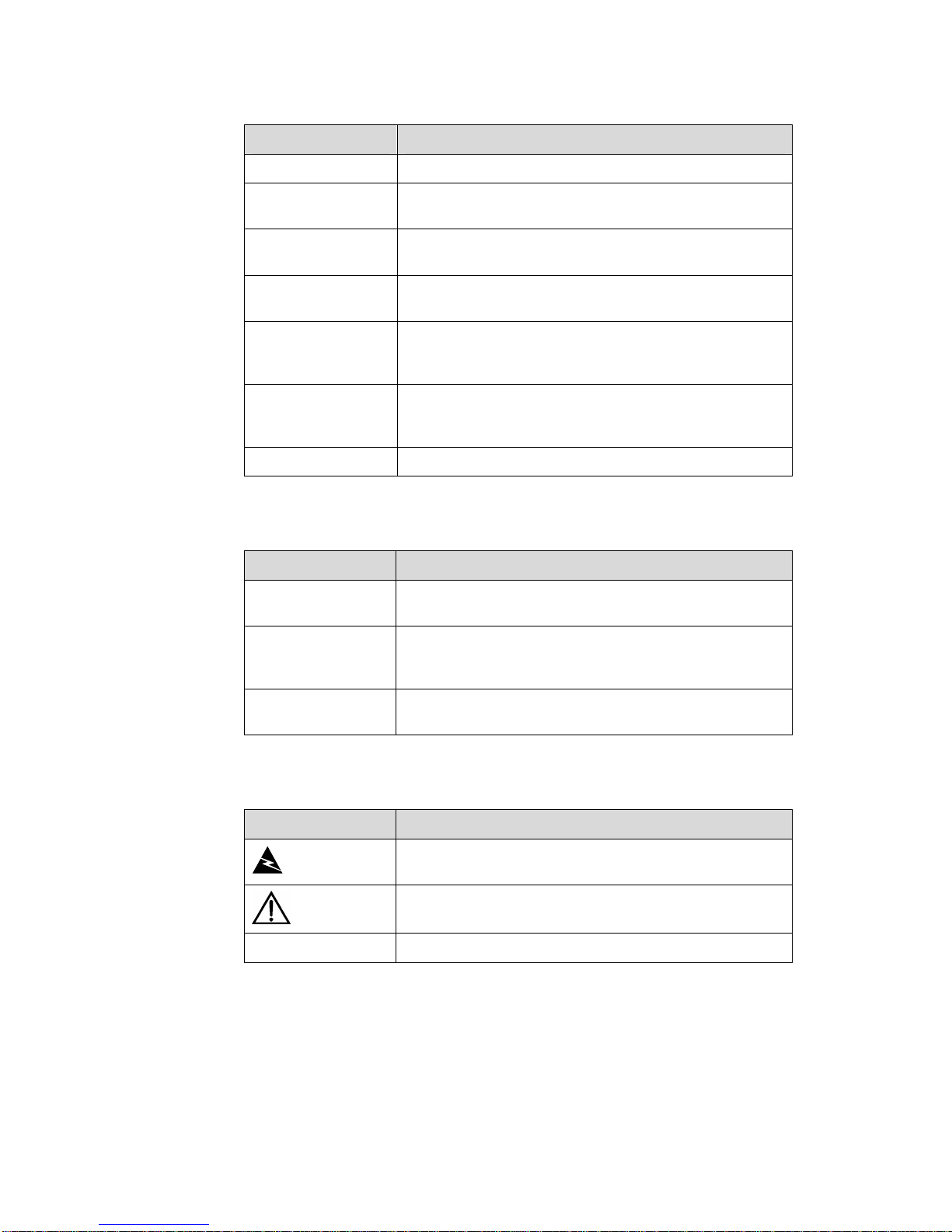
III. Symbols
Convention Description
Warning
Means reader be extremely careful. Improper operation
may cause bodily injury.
Caution
Means reader be careful. Improper operation may cause
data loss or damage to equipment.
Note Means a complementary description.
Page 5

Web-based Configuration Manual
H3C VG Series Voice Gateways Table of Contents
i
Table of Contents
Chapter 1 Introduction to VG.......................................................................................................1-1
Chapter 2 Getting Started with Configuration............................................................................2-1
2.1 Connecting Hardware........................................................................................................ 2-1
2.2 First Login..........................................................................................................................2-1
2.3 Interface Introduction......................................................................................................... 2-2
2.3.1 System Information Page........................................................................................ 2-2
2.3.2 List Display Page.....................................................................................................2-3
2.3.3 Configuration Item Page ......................................................................................... 2-4
2.3.4 Directory Tree..........................................................................................................2-7
Chapter 3 Web Configuration of VG............................................................................................ 3-1
3.1 Web Configuration Overview............................................................................................. 3-1
3.2 Detailed Web Configuration............................................................................................... 3-3
3.2.1 Voice Setup Wizard.................................................................................................3-3
3.2.2 Interface Configuration............................................................................................3-4
3.2.3 Static Route Configuration......................................................................................3-5
3.2.4 POTS Voice Entity Configuration............................................................................ 3-5
3.2.5 VoIP Voice Entity Configuration.............................................................................. 3-8
3.2.6 Fax Service Configuration.....................................................................................3-11
3.2.7 Voice Subscriber Line Configuration..................................................................... 3-13
3.2.8 Voice GK Client Configuration .............................................................................. 3-16
3.2.9 Dial Program Configuration................................................................................... 3-17
3.2.10 Voice AAA Configuration..................................................................................... 3-21
3.2.11 Voice Quality Configuration.................................................................................3-23
3.2.12 Global Property Configuration............................................................................. 3-24
3.3 Telnet Login to the VG..................................................................................................... 3-25
3.4 User Management........................................................................................................... 3-25
3.4.1 Adding a User........................................................................................................3-25
3.4.2 Login Method Configuration.................................................................................. 3-26
3.5 Save Configuration.......................................................................................................... 3-27
Page 6

Web-based Configuration Manual
H3C VG Series Voice Gateways Chapter 1
Introduction to VG
1-1
Chapter 1 Introduction to VG
H3C VG is a voice gateway device (hereinafter referred to as VG). It is developed by
Huawei-3Com Technology Co., Ltd. as a new generation of voice and fax access
equipment for various sectors and SOHO (small office and home office).
The VG is designed to access voice and fax signal, and convert the analog voice and
fax signal to digital signal, then packetize the digit al signal into IP packets, and send the
IP packets to the IP network through an Ethernet interface at the network side.
Additionally , some models, such as VG 10-40/10-41, can implement broadband access
of digital service, and provide an Ethernet interface at the user side to connect a PC or
a LAN.
The VG is cost-effective, for it integrates various IP telephone features, such as voice
over IP (VoIP), fax over IP (FoIP), call control, resource management, and
maintenance management, provides multiple coding/decoding modes, and supports
dynamic address acquisition.
The VG is compliant with H.323 of ITU-T and guarantees quality of voice and fax data
transmission over the IP network through high-performance DSP chips,
coding/decoding algorithms with a high compression ratio, echo cancellation, mute
compression, comfortable noise, jitter prevention, and relevant security and QoS
features.
The VG supports fast and non-fast connection to implement outband transmission of
the DTMF (dual tone multifrequency) code and provide busy tone detection,
abbreviated dialing, private lines, outgoing prefix, and some special services of
program-controlled switch (such as do-not-disturb, call forward o n busy, alarm call, and
multi-line group access).
At present, the VG provides Ethernet interfaces to connect with LAN and WAN, and
FXS (foreign exchange station) interfaces and FXO (foreig n exchange office) interfaces
to connect with ordinary telephone sets or PBX (private branch exchange).
Apart from providing SOHO users with IP telephone and fax services, the VG can
implement simultaneous transmission of voice and data by connecting with LAN
through Ethernet interfaces and thus make better use of the resources.
Page 7

Web-based Configuration Manual
H3C VG Series Voice Gateways Chapter 2
Getting Started with Configuration
2-1
Chapter 2 Getting Started with Configuration
2.1 Connecting Hardware
For a VG with two Ethernet interfaces:
The default IP address of the WAN interface is 192.168.192.1, with a subnet mask of
255.255.255.0.
The default IP address of the LAN interface is 192.168.193.1, with a subnet mask of
255.255.255.0.
For a VG with only one Ethernet interface:
The default IP address of the ETH interface is 192.168.192.1, with a subnet mask of
255.255.255.0.
Connect the Ethernet interface WAN or ETH with a PC through a network, and
configure the IP address of the PC on the same network segment as the default IP
address of the VG, and use the ping command to check the connection between the
VG and PC.
Note:
Users can modify the IP address of an Ethernet interface through Web configuration.
Once the IP address is modified, the default IP address will be deleted automatically.
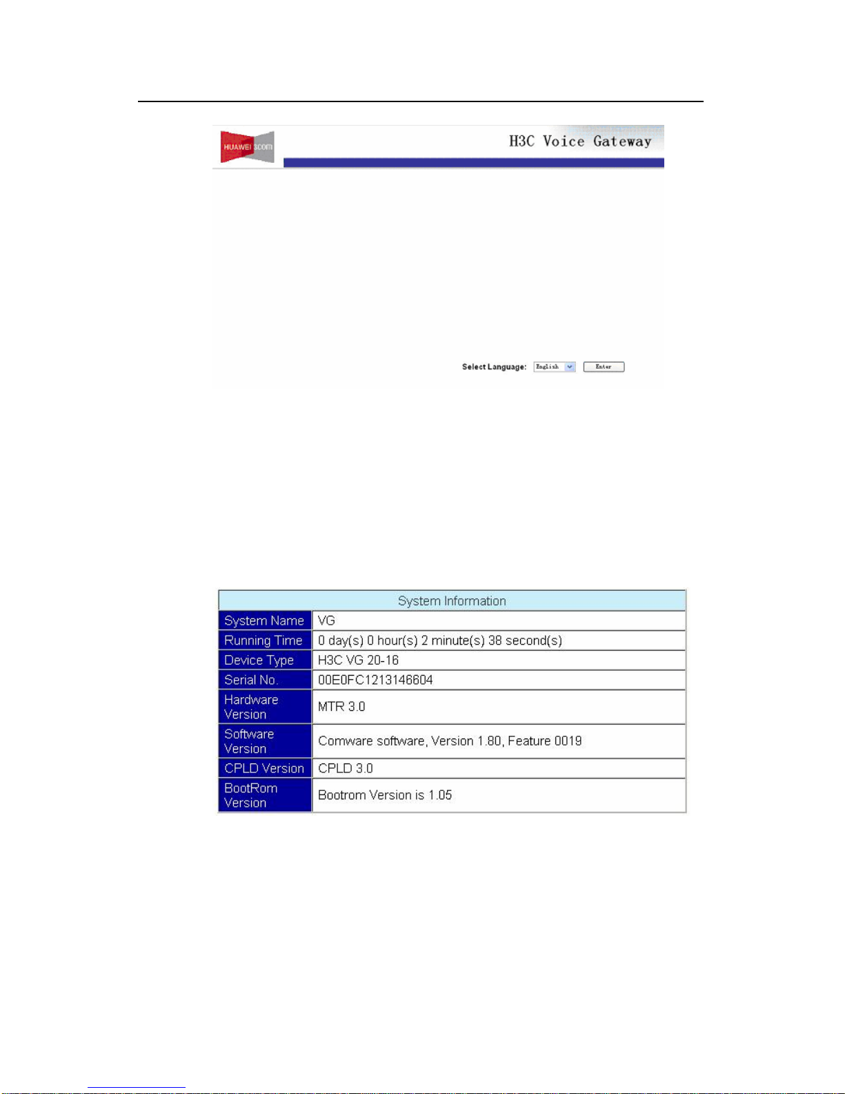
2.2 First Login
Open the explorer (IE5.0 or later recommended) and input the IP address
192.168.192.1 in the address bar. Press <Enter>, and a language selection page will
appear, as shown in
Figure 2-1.
Page 8
Web-based Configuration Manual
H3C VG Series Voice Gateways Chapter 2
Getting Started with Configuration
2-2
Figure 2-1 The language selection interface
Select a language, and click <Enter> to enter the configuration page.
2.3 Interface Introduction
2.3.1 System Information Page
The system information page displays basic system information about the VG.
Figure 2-2 The system information page
Page 9
Web-based Configuration Manual
H3C VG Series Voice Gateways Chapter 2
Getting Started with Configuration
2-3
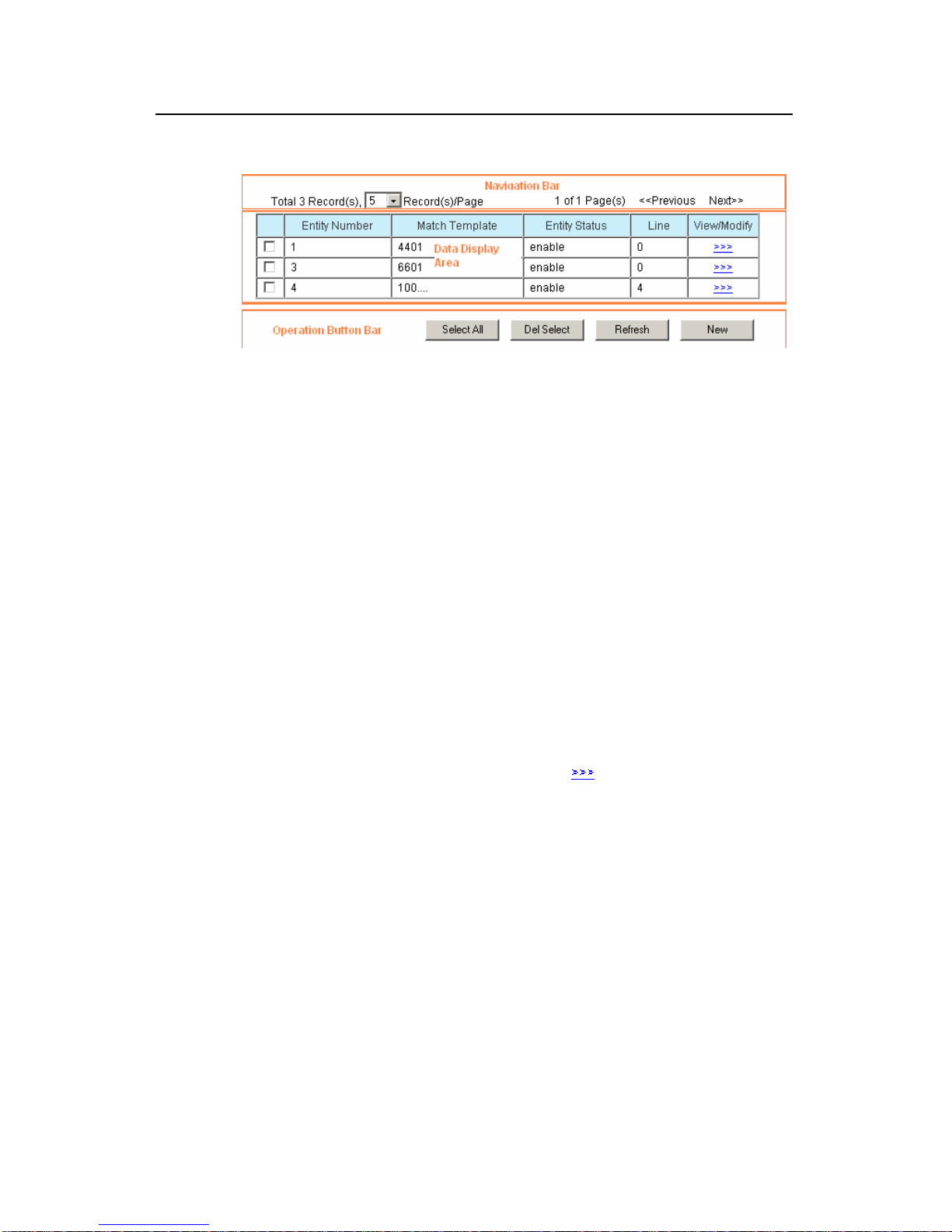
2.3.2 List Display Page
Figure 2-3 The list display page
The list display page consists of three parts: navigation bar, data display area and
operation button bar.
I. Navigation bar
The navigation bar is located at the uppermost part of the configuration a rea and used
to navigate to the data you want to view. Click the drop-down list box at the top left
corner to adjust the number of data displayed on each page. If one page cannot display
all data, you can turn to another page by clicking <<<Previous> or <Next>>> at the top
right corner.
II. Data display area
The data display area is located in the middle of the configuration area and displays the
content of data in a table.
z The first column of the table is a check box for deletion option. If the check box is
grey, it indicates you cannot delete this entry.
z On the last column is a property setting button . Press this button to enter the
page for setting the properties of the current data. A user can both view details of
the data on this page and modify some of properties (refer to the section
2.3.3
“Configuration Item Page”). If this column is not available in the table, it means the
data in the table cannot be modified. If a data entry has no modification button, it
means this data entry cannot be modified.
z The other columns of the table display the data information.
III. Operation button bar
The operation button bar is located at the bottom of the configuration area. The list
display page supports the following operations:
<Select All>: Selects all the data entries displayed in the current p age for the purpose of
deletion. Once clicked, the button will change automatically to <Cancel All> for
Page 10
Web-based Configuration Manual
H3C VG Series Voice Gateways Chapter 2
Getting Started with Configuration
2-4
canceling selection of all the entries. When <Cancel All> is clicked, the button will
return to <Select All> automatically.
<Del Select>: Deletes the selected data entry (entries). If no data entry is selected, a
dialogue box will pop up to prompt you to select a data entry.
<Refresh>: Asks the VG for the latest data of the current page.
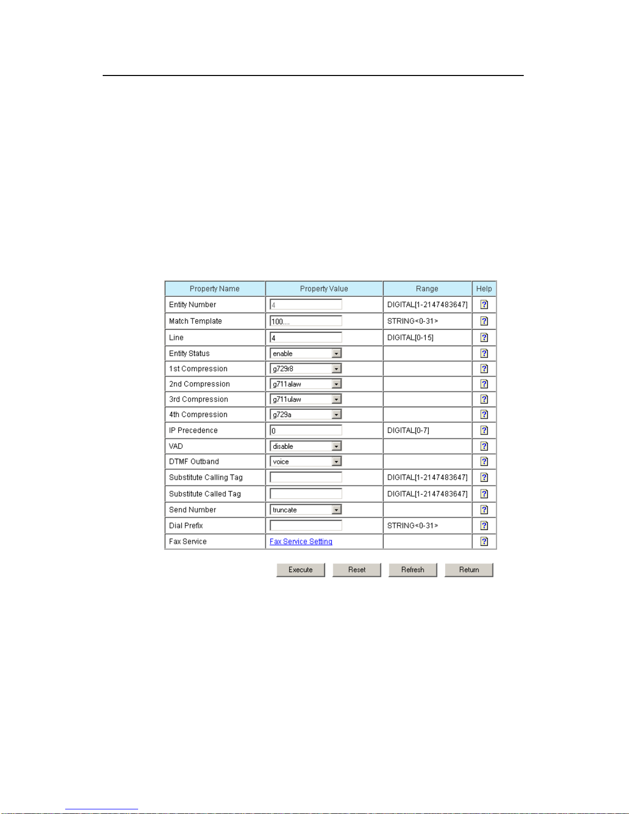
2.3.3 Configuration Item Page
The third type of page is a property setting page, which displays in a table the
properties you need to set as well as their related information. You can use the input
box or drop-down list box to set the properties. This kind of page is usually used to
create, modify and view property configuration.
Figure 2-4 The configuration item page
A property setting page consists of two parts: property setting table and operation
button bar.
I. Property setting table
A property setting table contains four columns:
The first one indicates the name of the property.
Page 11

Web-based Configuration Manual
H3C VG Series Voice Gateways Chapter 2
Getting Started with Configuration
2-5
The second one is a column for inputting a value for the property. There are two means
available for inputting a property value: direct typing in a text box and selecting from a
drop box.
In some cases two properties are associated. For example, when property A is
configured, property B will be made invalid. In such a case, the setting p age will perform
an automatic check when A is being configured. If A is configured with a value that will
make B invalid, the setting page will hide B automatically or turn the input box of B into
a disabled state (in grey), making it impossible for a user to input a value.
Besides, for some complex properties, such as the fax service property of the POTS
(plain old telephone service) entity, a hyperlink is provided in the input column. Users
can click this hyperlink to enter the configuration page.
Caution:
Except the “Voice Subscriber Line Description Information”, no data can contain “?”,
space or two-byte character (such as Chinese), or the system will display an error
prompt.
The third column describes the range of the property values. This description consists
of two parts. The first part indicates the type of data you can input, including digit al and
string. The second part specifies the size of data. It refers to a length when a string is
input and a range when digitals are input. For the strin g type, if it is 0, it means you are
allowed not to input any value for this property. Numbers [1-10] means that you must
input a number from 1 to 10 inclusively.
The fourth column is a link for detailed help information about the property. Click the
help icon
in this column to bring up the current property information.
II. Operation button bar
The operation button bar is located at the bottom of the configuration area. The
property setting page supports the following operations:
<Execute>: Submits the configuration data of the current page to the Web server (VG).
Page 12

Web-based Configuration Manual
H3C VG Series Voice Gateways Chapter 2
Getting Started with Configuration
2-6
Caution:
z Check the validity of each property value before submission.
z If an invalid property value is input, the system will display alarm information, and
the data will not be submitted for processing.
z If an error occurs when the VG is performing configuration, an error prompt page will
appear to indicate the cause, but the valid data submitted simultaneously are still
processed as usual.
z If the configuration is successful, it will return to the previous page of the current
configuration node (if there is no previous page, the current page remains.) For
example, after the POTS entity is configured successfully, it will return to the POTS
entity list display page. If global configuration of voice is successful, it will return to
the page for global configuration of voice, because this page has no previous pag e.
<Reset>: Cancels the modification made by the user to the values in the property input
box or drop-down list box.
<Refresh>: Asks the VG for the latest data of this current page. A configuration
modification page contains this button, while a newly created page does not.
<Return>: Returns to the previous page.
Caution:
z A list display page, property setting page and configuration error alarm pa ge support
return operation, which means to return to the previous page.
z The page classifications and descriptions above are applicable to most pages, but
some special pages, such as a configuration wizard page, may be a little different
from what have been described. Please refer to the description of specific pages.
Page 13

Web-based Configuration Manual
H3C VG Series Voice Gateways Chapter 2
Getting Started with Configuration
2-7
2.3.4 Directory Tree
Figure 2-5 Directory tree
Page 14

Web-based Configuration Manual
H3C VG Series Voice Gateways Chapter 3
Web Configuration of VG
3-1
Chapter 3 Web Configuration of VG
This manual introduces how to configure a VG through the Web pages, specifically by
describing VG configuration ideas and operation steps in tables. Since the VG has
many configuration parameters, this manual only introduces their basic prop erti es. For
detailed technical descriptions and configuration examples, refer to H3C VG Series
Voice Gateways Operation Manual and H3C VG Series Voice Gateways Command
Manual.
3.1 Web Configuration Overview
The VG provides configuration wizards to guide you through basic configurations. For
example, the Voice Set Wizard enables users to config ure basic VG functions. Refer to
section
3.2.1 “Voice Setup Wiza rd” for details.
The steps of basic VG configuration are as follows:
Step Operation Description
Related
section
Remarks
1.
Configure an
interface
Select [IP/IP Address] in the
directory tree, and select an
interface for accessing the user
network in the configuration page,
and click the
button in the
<View/Modify> column to set
interface parameters properly.
3.2.2 Required
2.
Configure a
static route
Select [IP/Static IP Route] in the
directory tree, and click <New> in
the configuration page to create a
static route.
3.2.3 Optional
3.
Configure a
POTS voice
entity
Select [Voice/POTS Entity] in the
directory tree, and click <New> or
a
button in the
<View/Modify> column in the
configuration page to set POTS
voice entity parameters.
3.2.4 Required
4.
Configure a
VoIP voice
entity
Select [Voice/VoIP Entity] in the
directory tree, and click <New> or
a
button in the
<View/Modify> column in the
configuration page to set VoIP
entity parameters.
3.2.5 Required
Page 15

Web-based Configuration Manual
H3C VG Series Voice Gateways Chapter 3
Web Configuration of VG
3-2
Related
Step Operation Description Remarks
section
5.
Configure fax
service
Select [Voice/VoIP Entity] or
[Voice/POTS Entity] in the
directory tree, and click <New> to
create a voice entity; or select a
voice entity and click the
button in the <View/Modify>
column. Then click <Fax Service
Setting> in the configuration page
to set fax service parameters.
3.2.6 Optional
6.
Configure a
voice
subscriber line
Select [Voice/Phone/Line] in the
directory tree, and click the
button in the <View/Modify>
column in the configuration item
page to set voice subscriber line
parameters.
3.2.7 Optional
7.
Configure a
voice
gatekeeper
(GK) client
Select [Voice/GK Client/GK Client]
in the directory tree, and set
proper GK client parameters in the
configuration page.
3.2.8 Optional
8.
Configure a
dial program
Select [Voice/Dial Program] in the
directory tree, select the desired
item, and set proper parameters in
the configuration page.
3.2.9 Optional
9.
Configure
voice AAA
Select [Voice/Voice AAA] in the
directory tree, select the desired
item, and set proper parameters in
the configuration page.
3.2.10 Optional
10.
Configure
voice quality
Select [Voice/Voice Quality] in the
directory tree, and set proper
parameters in the configuration
page.
3.2.11 Optional
11.
Configure
global
properties
Select [Voice/General] in the
directory tree, select the desired
item, and set proper parameters in
the configuration page.
3.2.12 Optional
12.
User
management
Select [User Management] in the
directory tree, select the desired
item, and set proper parameters in
the configuration page.
3.4 Optional
13.
Save
configuration
Select [Save Configuration] in the
directory tree, and click
<Confirm>.
3.5 Required
Page 16

Web-based Configuration Manual
H3C VG Series Voice Gateways Chapter 3
Web Configuration of VG
3-3
3.2 Detailed Web Configuration
3.2.1 Voice Setup Wizard
Step Operation Description Remarks
Basic configuration
1.
Configure an
IP address for
the interface
Select [Voice Setup Wizard] in the directory
tree, and set in the configuration page a
proper IP address and IP address mask for
the Ethernet interface used for user network
access. After finishing the configuration, click
<Next>.
Required
2.
Set a POTS
voice entity
Set parameters [Entity Number], [Match
Template], and [Line] in the configuration
page. After setting these parameters, click
<Add> to validate these configurations. Then
click <Next>.
The configured voice entity will be listed in
the lower part of the configuration page.
Required
3.
Set a VoIP
voice entity
Set parameters [Entity Number], [Match
Template], and [Address Type] in the
configuration page. After setting these
parameters, click <Add> to validate them.
Click <Finish> to complete the voice setup
wizard. Now the VG is configured with basic
voice functions.
If the [Address Type] is set to [IP], it is
necessary to specify the IP address of the
peer device.
The configured voice entity will be listed in
the lower part of the configuration item page.
Required
Return to section 3.1 “Web Configuration Overview”.
Note:
The IP address and IP address mask take the dotted decimal format.
For configuration details, refer to H3C VG Series Voice Gateways Operation Manual
and H3C VG Series Voice Gateways Command Manual.
Page 17

Web-based Configuration Manual
H3C VG Series Voice Gateways Chapter 3
Web Configuration of VG
3-4
3.2.2 Interface Configuration
Step Operation Description Remarks
Basic configuration
1.
Configure an
IP address for
the Ethernet
interface
Select [IP/IP Address] in the directory tree,
click <New>, set [Interface Type] to
[Ethernet], and [Interface Number] to 0 or 1
(depending on specific devices), and then set
[IP Address], [IP Address Mode] and [IP
Mask] properly.
To modify the existing configuration, click the
button in the <View/Modify> column
and set the [IP Address] and [IP Mask].
After configuring the parameters, click
<Execute> to validate the configurations. If
the address you have modified is the one that
you use to access the Web, log in to the VG
again using the new IP address.
Related command: ip address (interface
view).
Required
2.
Set the Dialer
interface
Select [IP/IP Address] in the directory tree,
click <New> in the configuration page, set
[Interface Type] to [Dialer], and [Interface
Number] to 0, and then set [IP Address], [IP
Address Mode] and [IP Mask] properly.
To modify the existing configuration, click the
button in the <View/Modify> column
and set the [IP Address] and [IP Mask].
Only VG 10-40 and VG 10-41 have a Dialer
interface.
Related command: ip address (interface
view).
Optional
3.
Set the
LoopBack
interface
Select [IP/IP Address] in the directory tree,
click <New> in the configuration page, set
[Interface Type] to [LoopBa ck], and [Interface
Number] to 1 or 2, and then set [IP Address],
[IP Address Mode] and [IP Mask] properly.
To modify the existing configuration, click the
button in the <View/Modify> column
and set the [IP Address] and [IP Mask].
Related command: ip address (interface
view).
Optional
Page 18

Web-based Configuration Manual
H3C VG Series Voice Gateways Chapter 3
Web Configuration of VG
3-5
Step Operation Description Remarks
4.
Configure a
secondary IP
address for the
interface
Select [IP/IP Address] in the directory tree,
click <New> in the configuration page, set
[Interface Type] and [Interface Number],
select [sub] as the [IP Address Mode], and
then set [IP Address] and [IP Mask] properly.
A Dialer interface cann ot be configured with a
secondary IP address.
Related command: ip address (interface
view).
Optional
Return to section 3.1 “Web Configuration Overview”.
3.2.3 Static Route Configuration
Step Operation Description Remarks
Basic configuration
1.
Create a static
route
Select [IP/Static IP Route] in the directory
tree, click <New>, and set [Destination IP],
[Destination IP Mask], [Next Hop Mode],
[Next Hop IP] or [Next Interface] and
[Precedence].
You can set only one of [Next Hop IP] and
[Next Interface], depending on the value of
[Next Hop Mode].
After configuring the parameters, click
<Execute> to validate the configurations.
Related command: ip route-static (system
view).
Optional
Return to section 3.1 “Web Configuration Overview”.
3.2.4 POTS Voice Entity Configuration
Step Operation Description Remarks
Basic configuration
1.
Create a
POTS voice
entity
Select [Voice/POTS Entity] in the directory
tree, and click <New> in the configuration
page to set POTS voice entity parameters.
Required
2.
Modify POTS
voice entity
parameters
Select [Voice/POTS Entity] in the directory
tree, click the
button in the
<View/Modify> column in the configuration
page, and set POTS voice entity parameters.
Required
Page 19

Web-based Configuration Manual
H3C VG Series Voice Gateways Chapter 3
Web Configuration of VG
3-6
Step Operation Description Remarks
3.
Configure an
entity number
The entity number identifies a voice entity
uniquely . PO TS voice entities and VoIP voice
entities are numbered uniformly for easy
management.
Related command: entity (voice dial program
view).
Required
4.
Configure a
called number
match
template
The VG implements a voice call by matching
the called voice entity with the string
configured in this template.
Related command: match-template (voice
entity view).
Required
5.
Configure a
voice port
The VG associates a voice entity with a voice
subscriber line through this port to relate a
logical entity and a physical line.
Related command: line (POTS voice entity
view).
Required
6.
Configure
voice entity
status
This parameter is designed to control the
running status of a voice entity. If a voice
entity is disabled, it cannot receive a voice
call.
Related command: shutdown (voice entity
view).
Related command: undo shutdown (voice
entity view).
Optional
Advanced configuration
-
Configure
voice codec
type
Set a voice decoding precedence mode for
the VG according to the bandwidth of the
user network and different requirements on
voice quality. There are four precedence
classes.
Related command: compression (voice
entity view).
Optional
-
Configure
voice IP
packet
precedence
You can set higher precedence for the voice
and fax IP packets related with a voi ce entity,
so that devices on the data transmission path
will preferentially process these packets.
Related command: ip-precedence (voice
entity view).
Optional
Page 20

Web-based Configuration Manual
H3C VG Series Voice Gateways Chapter 3
Web Configuration of VG
3-7
Step Operation Description Remarks
-
Configure
mute detection
The VG can detect and delete mute
according to the energy levels of voice signal
and silence signal of daily conversations, and
will not produce and transmit voice signal
until it detects abrupt active sound. This can
effectively decrease occupancy of network
bandwidth.
While using this function, you are
recommended to enable the comfortable
noise function.
Related command: vad-on (voice entity
view).
Optional
-
Configure
DTMF
transmission
mode
By default, the inband transmission mode is
applied to the DTMF code. Outband
transmission means the DTMF code is
transported through H.245 and H.225.
Related command: outband (voice entity
view).
Optional
-
Number of the
calling number
transform rule
table
This number is used to relate the calling
number transform rule table with a voice
entity.
Related command: substitute calling (voice
entity view).
Optional
-
Number of the
called number
transform rule
table
This number is used to relate the called
number transform rule table with a voice
entity.
Related command: substitute called (voice
entity view).
Optional
- Send Number
This parameter is used to control how to send
a called number to the PSTN.
The VG sends a called number in three ways:
1) Sending part of the number extracted from
right to left and with a specified length;
2) Sending all digits of the number;
3) Sending the called number by means of
truncation.
Related command: send-number (POTS
voice entity view).
Optional
- Dial Prefix
When “truncate” (default) is set for sending a
called number, the VG will remove from the
called number the left part string that exactly
matches the match template. The dial prefix
will be added before the remaining string, and
the VG will call the new string.
Related command: match-template (voice
entity view).
Optional
Page 21

Web-based Configuration Manual
H3C VG Series Voice Gateways Chapter 3
Web Configuration of VG
3-8
Step Operation Description Remarks
- Fax Service
For fax parameter setting, refer to section
3.2.6 “Fax Service Configuration”.
Optional
Return to section 3.1 “Web Configuration Overview”.
3.2.5 VoIP Voice Entity Configuration
Step Operation Description Remarks
Basic configuration
1.
Create a VoIP
voice entity
Select [Voice/VoIP Entity] in the directory
tree, and click <New> in the configuration
page to set VoIP voice entity parameters.
Optional
2.
Modify VoIP
voice entity
parameters
Select [Voice/VoIP Entity] in the directory
tree, click the
button in the
<View/Modify> column in the configuration
page, and set VoIP voice entity
parameters.
Optional
3.
Configure an
entity number
The entity number uniquely identifies a
voice entity. VoIP voice entities and POTS
voice entities are numbered uniformly for
easy management.
Related command: entity (voice dial
program view).
Required
4.
Configure a
called number
match template
The VG implements a voice call by
matching the called voice entity with the
string configured in this template.
Related command: match-template
(voice entity view).
Required
5.
Configure voice
entity routing
mode
After matching a VoIP voice entity with the
called number, the VG maps the called
number with the called gateway IP address
in the voice entity routing mode.
The modes available are:
z Configuring a static IP address for the
called gateway;
z Interacting with GK to map the called
number and the IP address;
z No routing.
Related command: address (VoIP voice
entity view).
Required
Page 22

Web-based Configuration Manual
H3C VG Series Voice Gateways Chapter 3
Web Configuration of VG
3-9
Step Operation Description Remarks
6.
Configure voice
entity status
This parameter is designed to control the
running status of a voice entity. If a voice
entity is disabled, it cannot receive a voice
call.
Related command: shutdown (voice
entity view).
Related command: undo shutdown
(voice entity view).
Optional
Advanced configuration
-
Configure an
area ID
In VoIP voice entity view, set a voice area
ID, which will be added automatically to the
beginning of a called number when a call is
made.
Related command: area-id (VoIP voice
entity view).
Optional
-
Configure voice
coding/decodin
g mode
Set a voice decoding preference mode for
the VG according to the bandwidth of the
user network and different requirements on
voice quality. There are four precedence
classes.
Related command: compression (voice
entity view).
Optional
-
Configure voice
IP packet
precedence
You can set higher precedence for the
voice and fax IP packets related with a
voice entity, so that devices on the data
transmission path will preferentially
process these packets.
Related command: ip-precedence (voice
entity view).
Optional
-
Configure mute
detection
The VG can detect and delete mute
according to the energy levels of voice
signal and silence signal of daily
conversations, and will not produce and
transmit voice signal until it detects abrupt
active sound. This can effectively
decrease occupancy of network
bandwidth.
While using this function, you are
recommended to enable the comfortable
noise function.
Related command: vad-on (voice entity
view).
Optional
Page 23

Web-based Configuration Manual
H3C VG Series Voice Gateways Chapter 3
Web Configuration of VG
3-10
Step Operation Description Remarks
-
Configure fast
connection
This function can reduce information
exchanged between the calling and called
parties before a call is established, thus
quickening setup of the call. This function
requires support of both the calling and
called parties.
Related command: fast-connect (VoIP
voice entity view).
Optional
-
Configure
tunnel function
The tunnel function must be enabled when
transparent transmission of the DTMF
code is performed in the fast connection
mode.
This parameter can be configured only
when the fast connection function is
enabled.
Related command: tunnel-on (VoIP voice
entity view).
Optional
-
Configure
ring-back tone
This parameter is used to configure
sending ring-back tone locally.
This parameter can be configured only
when the fast connection function is
enabled.
Related command: send-ring (VoIP voice
entity view).
Optional
-
Configure
DTMF
transmission
mode
By default, the inband transmission mode
is applied to the DTMF code. Outband
transmission means the DTMF code is
transported through H.245 and H.225.
Related command: outband (voice entity
view).
Optional
-
Number of the
calling number
transform rule
table
This number is used to bind the calling
number transform rule table with a voice
entity.
Related command: substitute calling
(voice entity view).
Optional
-
Number of the
called number
transform rule
table
This number is used to bind the called
number transform rule table with a voice
entity.
Related command: substitute called
(voice entity view).
Optional
- Fax Service
For fax parameter setting, refer to section
3.2.6 “Fax Service Configuration”.
Optional
Return to section 3.1 “Web Configuration Overview”.
Page 24

Web-based Configuration Manual
H3C VG Series Voice Gateways Chapter 3
Web Configuration of VG
3-11
3.2.6 Fax Service Configuration
Step Operation Description Remarks
Advanced configuration
-
Configure fax
ECM mode
A fax machine that adopt s ECM has the error
correction function and can provide ARQ
(automatic repeat request) and transmit fax
packets in the HDLC frame format. In
contrast, a fax machine that adopts a mode
(supported) other than ECM has no error
correction function, and transmits fax
information in the binary format.
ECM is applicable to fax only when the fax
machines at both ends support ECM and the
gateway adopts ECM as well.
Related command: fax ecm (voice entity
view).
Optional
-
Configure
non-standard
fax facilities
In ordinary fax applications, the fax terminals
of both parties negotiate through standard
facilities (such as V.17 or V.29 rate) by
default, that is, they send no NSF
(non-standard facilities) message frame. In
some cases (such as encrypted fax),
non-standard facilities become very
important to fax communication. Therefore
in such cases, fax terminals of both parties
exchange NSF message frames to start the
negotiation, and then negotiate on other fax
facilities for communication.
Related command: fax nsf-on (voice entity
view).
Optional
-
Configure fax
rate
If the fax baudrate is set to a value other than
“disable” and “voice”, rate negotiation is
performed preferentially through the fax
protocol corresponding to this rate. The rate
configured here is an allowed maximum rate
instead of a specified rate in use.
Related command: fax baudrate (voice
entity view).
Optional
Page 25

Web-based Configuration Manual
H3C VG Series Voice Gateways Chapter 3
Web Configuration of VG
3-12
Step Operation Description Remarks
-
Configure fax
training mode
Local training mode means that the
gateways join in the rate training between
the fax machines at two ends. In this mode,
the training is first performed at the two ends
respectively (that is, between the receiving
fax machine and the receiving gateway, and
between the sending fax machine and the
sending gateway). Then the receiving
gateway sends the training result of the
receiving party to the gateway of the sending
party, and the gateway of the sending party
determines the final packet transmission
rate according to the training results of the
two parties.
Related command: fax train-mode (voice
entity view).
Optional
-
Configure
energy level of
sending fax
gateway carrier
The default energy level of sending gateway
carrier applies to most cases. If the faxing
fails when other configurations are correct,
you can try adjusting the energy level of
sending gateway carrier. The smaller the
energy level, the larger the energy.
Related command: fax level (voice entity
view).
Optional
-
Configure fax
protocol
The VG supports two fax start modes: H.323
negotiation start mode and VG negotiation
start mode, corresponding respectively to
fax protocols H.323-T.38 and T.38.
Moreover, the VG can provide transparent
transmission fax through two configurations.
1) Configuring the fax protocol to PCM.
2) Configuring the two-party voice
coding/decoding negotiation to G.711 and
“Fax Baudrate” to “disable” (disable fax
forward), and disabling mute detection
(VAD) to prevent fax failure. This mode is
applicable to transparent transmission
interworking with other devices.
Related command: fax protocol (voice
entity view).
Optional
Page 26

Web-based Configuration Manual
H3C VG Series Voice Gateways Chapter 3
Web Configuration of VG
3-13
Step Operation Description Remarks
-
Configure the
number of high
speed
redundancy
packets sent
via T.38
The VG supports control on high speed and
low speed redundancy packets. Increasing
the number of redundancy packets can
improve reliability of network transmission
and reduce the trouble caused by packet
loss. But too many redundancy packets will
largely increase bandwidth utilization, and
affect fax quality gravely if the bandwidth is
small. Therefore, the number of redundancy
packets should be based on network
bandwidth.
This parameter is available when [Fax
Protocol] is set to “h323-t38” or “T.38”.
Related command: fax redundancy
hb-redundancy (voice entity view).
Optional
-
Configure the
number of low
speed
redundancy
packets sent
via T.38
This parameter is available when [Fax
Protocol] is set to “h323-t38” or “T.38”.
Related command: fax redundancy
lb-redundancy (voice entity view).
Optional
-
Configure fax
Passthrough
mode
When the [Fax Protocol] is set to “pcm”, you
should set a voice coding/decoding rate for
fax transparent transmission.
Related command: fax protocol pcm (voice
entity view).
Optional
-
Configure fax
transmission
format
When the T.38 protocol is applied, the RTP
mode (the corresponding parameter is rtp)
is often used. To interwork with the VocalTec
gateway, set the VT mode (the
corresponding parameter is vt).
Related command: fax support mode
(voice entity view).
Optional
Return to section 3.1 “Web Configuration Overview”.
3.2.7 Voice Subscriber Line Configuration
Step Operation Description Remarks
Basic configuration
1.
Modify voice
subscriber
line
parameters
Select [Voice/Phone/Line] in the directory
tree, and click the
button in the
<View/Modify> column in the configuration
page to set voice subscriber line parameters.
Optional
Page 27

Web-based Configuration Manual
H3C VG Series Voice Gateways Chapter 3
Web Configuration of VG
3-14
Step Operation Description Remarks
2.
Configure
description
Describe the voice subscriber line.
Related command: description (voice
subscriber line view).
Optional
3.
Configure
comfortable
noise
When VAD is enabled for a voice entity, mute
intervals may exist during the voice
conversation. You can use this command to
produce proper background noise to fill the
mute intervals.
Related command: cng-on (voice subscriber
line view).
Required
4.
Configure a
private line
number
If you have configured a private line number,
the VG will automatically originate a call to
this configured number after you pick up the
phone (no other operation is needed).
Related command: private-line (voice
subscriber line view).
Optional
5.
Configure dial
timeout time
Dial timeout time refers to the timer interval
during which the system waits for a user to
dial the next digit.
When a user dials a digit, this timer is reset.
This process is repeated until all digits are
dialed. If timeout occurs before dialing is
finished, the user will be prompted to hang up
and the dialing is ended.
Related command: timer dial-interval (voice
subscriber line view).
Optional
6.
Configure
FXO port
binding
Specify the FXO port to be bound with the
current FXS port.
After being bound, an FXO port can be used
by the corresponding FXS port only. After an
FXS-FXO binding is created:
z When a call is sent from the FXS port, the
bound FXO port has the priority to direct it.
z When the FXO receives a call from the
PSTN, it directly sends it to the bound FXS
port through the dedicated line.
Related command: bind (voice subscriber
line view).
Optional
Advanced configuration
Page 28

Web-based Configuration Manual
H3C VG Series Voice Gateways Chapter 3
Web Configuration of VG
3-15
Step Operation Description Remarks
-
Configure
echo
cancellation
During conversation, your voice is repeated
for the line reason and returned to your
receiver. This is called echo. The cause is
leaking of analog voice signals to your own
receiving path. You can solve the echo
problem in conversation to some extent
through the echo cancellation function
provided by the VG.
Related command: echo-canceller enable
(voice subscriber line view).
Optional
-
Configure
echo
cancellation
duration
Echo duration means the interval from the
time a user makes an original sound to the
time the echo is heard. The VG deals with
echo cancellation according to this parameter .
Related command: echo-canceller
tail-length (voice subscriber line view).
Optional
-
Configure
voice input
gain
When attenuation of voice signal on a line is
large, this command can be used to properly
increase voice input gain.
Related command: receive gain (voice
subscriber line view).
Optional
-
Configure
voice output
gain
When the power of voice signal on the output
line is small, this command can be used to
increase proper voice output attenuation to
meet the signal requirements of the output
line.
Related command: transmit gain (voice
subscriber line view).
Optional
-
Number of the
calling
number
transform rule
table
This number is used to bind the calling
number transform rule table with a voice
subscriber line.
Related command: substitute calling (voice
subscriber line view).
Optional
-
Number of the
called number
transform rule
table
This number is used to bind the called number
transform rule table with a voice subscriber
line.
Related command: substitute called (voice
subscriber line view).
Optional
Return to section 3.1 “Web Configuration Overview”.
Note:
FXO port binding is supported by the VG 31-08 and VG 10-41 only, in Web-based
configuration mode.
Page 29

Web-based Configuration Manual
H3C VG Series Voice Gateways Chapter 3
Web Configuration of VG
3-16
3.2.8 Voice GK Client Configuration
Step Operation Description Remarks
Basic configuration
1.
Inquire voice
GK client
status
Select [Voice/GK Client/GK Client Status],
and the information of start status and
registration status is listed in the
configuration page.
Optional
2.
Configure GK
client
parameters
Select [Voice/GK Client/GK Client] in the
directory tree, and set GK client parameters
in the configuration page.
Optional
3.
Configure a
gateway alias
This parameter is used by the gateway to
register and identify a VG in the GK Server. A
gateway can have only one alias, and a new
alias will override the old one.
Related command: gw-id (voice GK view).
Required
4.
Configure a
gateway
source
address
If a source IP address is configured for the
VG (this is also referred to as source address
binding), all the packets must use this u nified
source address, no matter which physical
interface the voice IP packets are sent out
from. Since the transmitted voice IP packets
contain a unified and definite source
address, packet filtering becomes very
simple, making firewall control easier.
Related command: gw-address (voice GK
view).
Required
5.
Configure a
name for the
active GK
Server
When the GK Client function of the VG is
enabled, the GK Client will register
information about this gateway with the
active GK Server, so it is necessary to
configure an IP address and name for the
active GK Server to make it easier to locate
the right GK Server.
Related command: gk-id (voice GK view).
Required
6.
Configure an
IP address for
the active GK
Server
This parameter is designed to configure for
the active GK Server an IP address, which is
used by the gateway to register with GK.
Related command: gk-id (voice GK view).
Required
7.
Configure a
port for the
active GK
Server
This parameter is designed to configure for
the active GK Server a RAS listening port,
which is used by the gateway to register with
GK.
Related command: gk-id (voice GK view).
Optional
Page 30

Web-based Configuration Manual
H3C VG Series Voice Gateways Chapter 3
Web Configuration of VG
3-17
Step Operation Description Remarks
8.
Configure GK
Client Status
The VG can communicate normally with GK
Server only after the GK Client function is
enabled, or it will be unable to set up a
connection with GK Server.
Related command: ras-on (voice GK view).
Required
9.
Configure GK
management
on local calls
Select [Voice/GK Client/GK Client], and
select the disable option for [GK Local Call]
on the configuration page to enable GK
management on local calls.
Related command: gk-local-call (voice GK
view).
Optional
Advanced configuration
-
Configure a
name for the
standby GK
Server
When communication between the GK Client
and the active GK Server becomes abnormal
(for example, times out), or the active GK
Server is unavailable, the VG can
alternatively send a registration request to
the standby GK Server.
Related command: gk-2nd-id (voice GK
view).
Optional
-
Configure an
IP address for
the standby
GK Server
This parameter is designed to configure for
the standby GK Server an IP address, which
is used by the gateway to register with GK.
Related command: gk-2nd-id (voice GK
view).
Optional
-
Configure a
port for the
standby GK
Server
This parameter is designed to configure for
the standby GK Server a RAS listening port,
which is used by the gateway to register with
GK.
Related command: gk-2nd-id (voice GK
view).
Optional
Return to section 3.1 “Web Configuration Overview”.
3.2.9 Dial Program Configuration
I. Configuring dial control
Step Operation Description Remarks
Basic configuration
1.
Configure dial
program
Select [Voice/Dial Program] in the directory
tree, select the items you want to configure,
and set proper parameters in the
configuration page.
Optional
Page 31

Web-based Configuration Manual
H3C VG Series Voice Gateways Chapter 3
Web Configuration of VG
3-18
Step Operation Description Remarks
2.
Configure a
dial terminator
A dial terminator is used to notify the VG that
the dialing is ended, and the VG should set up
a call using the received number.
Related command: terminator (voice dial
program view).
Required
3.
Configure
number match
mode
When a user is dialing a number to set up a
call, the direction in which the call is originated
depends on the called number template,
namely, the number preset in the match
template. If longest number match is applied,
the system will match as long a number as
possible. During dialup, as long as it is still
possible for the input number to match a
longer called number template, the system
will wait for a longer number to be input. In
case of wait timeout, the system will use the
dialed number for matching. If shortest
number match is applied, whenever the input
number matches a called number template, a
call will be originated, and the digits the user
continues to dial will be neglected.
Related command: number-match (voice
dial program view).
Required
Return to section 3.1 “Web Configuration Overview”.
II. Configuring number transform
Step Operation Description Remarks
Basic configuration
1.
Create a
number
transform rule
table
Select [Voice/Dial Program/Number
Substitution] in the directory tree, and click
<New> in the configuration page to set
number transform parameters.
Required
2.
Configure a
number for
the number
transform rule
table
This parameter is used to set a unique
identification for a number transform rule
table.
Related command: number-substitute
(voice dial program view).
Required
3.
Configure the
dot-number
match rule
In the input format of the number transform
rule, the numbers that will be retained are
marked with “.”, of which the quantity and
position are configured in the output format of
the number transform rule.
Related command: dot-match (voice dial
program view).
Optional
Page 32

Web-based Configuration Manual
H3C VG Series Voice Gateways Chapter 3
Web Configuration of VG
3-19
Step Operation Description Remarks
4.
Configure a
preferred
transform tag
This is the number transform rule that is first
applied to the current number transform table.
Related command: first-rule (voice number
transform view).
Optional
5.
Modify a
number
transform rule
table
Select [Voice/Dial Program/Number
Substitution] in the directory tree, and click the
button in the <View/Modify> column in
the configuration page to set number
transform parameters.
Related command: number-substitute
(voice dial program view).
Required
6.
Configure
transform
rules
Click the configuration item “Rule Table”, and
click <New> to set parameters of number
transform rules.
Related command: rule (voice number
transform view).
Required
7.
Configure
transform rule
tags
A transform rule tag is used as a unique
identification of a transform rule in the number
transform rule table.
Related command: rule (voice number
transform view).
Required
8.
Configure the
input format
This is an input string for number
transformation.
Related command: rule (voice number
transform view).
Required
9.
Configure the
output format
This is an output string of number
transformation.
Related command: rule (voice number
transform view).
Required
Return to 3.1 Web Configuration Overview.
III. Configuring access service numbers
Step Operation Description Remarks
Basic configuration
1.
Create an
access
service
number
Select [Voice/Dial Program/Access Service
Number] in the directory tree, and click
<New> in the configuration page to set
access service number paramet e rs.
Related command: gw-access-number
(voice dial program view).
Required
Page 33

Web-based Configuration Manual
H3C VG Series Voice Gateways Chapter 3
Web Configuration of VG
3-20
Step Operation Description Remarks
2.
Modify an
access
service
number
Select [Voice/Dial Program/Access Service
Number] in the directory tree, and click the
button in the <View/Modify> column in
the configuration page to set access service
number parameters.
Related command: gw-access-number
(voice dial program view).
Required
3.
Configure
dialing
process
Each access service, corresponding to an
access service number, has a specific dialing
process. Any user that uses an access
service can set up a call only through the
corresponding process.
Related command: process-config (access
service number view).
Required
4.
Configure
redial times
Dialing failure is possible in each dialing stage
due to wrong input, so this parameter is
designed to set the allowed redial times.
Related command: redialtimes (access
service number view).
Optional
5.
Configure the
digits of a card
number
This parameter is used to set the digits of a
card number for the users that use the
dual-stage dialing card number process (card
number/password authentication). Once the
digits of a card number is set, users can use
this access service number only through a
card number with preset digits.
This parameter is valid only when the dialing
process is set to “Card Number”.
Related command: card-digit (access
service number view).
Optional
6.
Configure
password digit
This parameter is used to set the digits of a
user’s password needed when the dialing
process is set to “Card Number”.
Related command: password-digit (access
service number view).
Optional
7.
Configure
authentication
For each access service number, you can
specify whether to authenticate users that use
the corresponding service. If you enable user
authentication for an access service, users
that use this service cannot be authorized to
make IP calls until they pass the
authentication. If authentication is disabled,
all the users (legal or illegal) that use this
number can make IP calls without
authentication.
Related command: authentication (access
service number view).
Optional
Page 34

Web-based Configuration Manual
H3C VG Series Voice Gateways Chapter 3
Web Configuration of VG
3-21
Step Operation Description Remarks
8.
Configure
authorization
“Authorization” is to determine what kind of IP
call (local, domestic toll, or international toll) a
user can place according to the user’s right
and application (the called number).
Related command: authorization (access
service number view).
Optional
Return to section 3.1 “Web Configuration Overview”.
3.2.10 Voice AAA Configuration
I. Configuring authentication and authorization for single-stage dialing users
Step Opera tion Description Remarks
Basic configuration
1.
Configure
authentication
For the single-stage dialing (direct dialing
without need of an access service number)
users, it is impossible to enable
authentication on a single user because no
access service number is applied. In this
case, authentication can be performed only
on all users.
Related command: authentication-did
(access service number view).
Optional
2.
Configure
authorization
For the single-stage dialing (direct dialing
without need of an access service number)
users, it is impossible to enable authorization
on a single user because no access service
number is applied. In this case, authorization
can be performed only on all users. Before
enabling authorization, be sure to enable
authentication.
Related command: authorization-did
(access service number view).
Optional
Return to section 3.1 “Web Configuration Overview”.
II. Configuring call record properties
Step Operation Description Remarks
Basic configuration
1.
Configure the
output
threshold of
call records
Y ou can save call records by setting an output
threshold (in percentage) for them.
Related command: cdr threshold (voice AAA
service view).
Optional
Page 35

Web-based Configuration Manual
H3C VG Series Voice Gateways Chapter 3
Web Configuration of VG
3-22
Step Operation Description Remarks
2.
Configure
maximum call
records
You can save call records by setting a
maximum number of records.
Related command: cdr buffer (voice AAA
service view).
Optional
3.
Configure
maximum
duration for
saving
detailed call
records
You can save call records by setting
maximum saving duration (from the end of
conversation).
Related command: cdr duration (voice AAA
service view).
Optional
Return to section 3.1 Web Configuration Overview.
III. Configuring local voice users
Step Operation Description Remarks
Basic configuration
1.
Create a local
voice user
Select [Voice/Voice AAA/Local Voice Users]
in the directory tree, and click <New> in the
configuration page to set parameters for the
new local voice user.
Optional
2.
Modify a local
voice user
Select [Voice/Voice AAA/Voice Local User] in
the directory tree, and click the
button in
the <View/Modify> column in the
configuration page to modify local voice user
parameters.
Optional
3.
Configure a
local user
name
When the local voice user database is
configured, local authentication is performed
preferentially on voice users. If the local
authentication succeeds, the subsequent
RADIUS authentication will be omitted. If the
local authentication fails, authentication will
be performed on the RADIUS server. If the
RADIUS authentication succeeds, the user
can make voice communication; otherwise it
will be rejected. At preset, the VG can support
up to 200 local users.
Related command: local-user (voice AAA
service view).
Required
4.
Configure a
local user
password
This parameter is used to configure
passwords for local voice users.
Related command: local-user (voice AAA
service view).
Required
Return to section 3.1 “Web Configuration Overview”.
Page 36

Web-based Configuration Manual
H3C VG Series Voice Gateways Chapter 3
Web Configuration of VG
3-23
3.2.11 Voice Quality Configuration
Step Operation Description Remarks
Advanced configuration
1.
Configure
voice quality
Select [Voice/Voice Quality] in the directory
tree, and set proper voice quality parameters
in the configuration page.
Voice data can be forwarded in the normal or
fast mode. Fast forwarding is subd ivided into
fast receiving and fast sending. Users can
adopt different forwarding modes to satisfy
varied requirements on voice performance.
Optional
2.
Configure
voice data
receiving
process
Compared with the normal receiving process,
the fast receiving process omits the memory
application and data copy process, and sends
the data directly to the service module for
processing, thus quickening voice data
receiving.
Related command: vqa performance
receive (voice view).
Optional
3.
Configure
voice data
sending
process
The fast sending process packetizes voice
data with the aid of interruption mechanism,
and then, according to the route and link
information, sends the packets directly to the
network layer for forwarding.
Related command: vqa performance send
(voice view).
Optional
4.
Configure
voice data
statistics
To locate and debug quickly and accurately a
problem occurring to a VoIP call, you can use
this parameter to display the voice data
statistics. The statistic information includes
times of success in searching voice tables,
total number of received packets, times of
searching voice tables in the fast and ordinary
ways, and information of various items (such
as voice and fax) on the receiving and
sending channel.
Related command: vqa d ata- stati sti c (voice
view).
Optional
5.
Anti-Jitter
buffer level
To relieve negative influence of network
status on the voice packets, you can use the
Jitter Buffer to process the voice packets.
These measures include compensating for
the lost packets, adjusting the disordered
packets, deleting the packets that cause jitter,
and discarding the packets with duplicate
serial numbers.
Related command: vqa jitter-buffer (voice
view).
Optional
Page 37

Web-based Configuration Manual
H3C VG Series Voice Gateways Chapter 3
Web Configuration of VG
3-24
Step Operation Description Remarks
6.
Configure
global packet
precedence
This parameter is to configure precedence for
all voice IP packets (TOS domain of the IP
packets).
The numeral 0 indicates the highest
precedence, and 7 the lowest.
Related command: vqa ip-precedence
(voice view).
Optional
Return to section 3.1 “Web Configuration Overview”.
3.2.12 Global Property Configuration
I. Configure global voice properties
Step Operation Description Remarks
Basic configuration
1.
Configure
start mode of
the called
party
When the VG is configured as the called
party, this parameter is used to negotiate with
the peer about the call start mode.
Related command: voip call-start (voice
view).
Optional
2.
Configure
called tunnel
function
To use the H.323 protocol to interwork with a
device that does not support tunnel function,
you need to use this command to configure
the called gateway to disable the tunnel
function.
Related command: voip calledtunnel (voice
view).
Optional
3.
Configure 1:1
binding of
analog ports
After 1:1 binding is configured for the device,
all FXS and FXO ports are bound, with port
FXSn corresponding to FXOn respectively,
and vice versa. Here n ranges from 0 to 7.
Being bound, an FXO port serves for the
related FXS port only.
Related command: bindmode (voice view).
Optional
Return to section 3.1 “Web Configuration Overview”.
Note:
1:1 binding for analog ports is supported by the VG 31-08 only, in Web-based
configuration mode.
Page 38

Web-based Configuration Manual
H3C VG Series Voice Gateways Chapter 3
Web Configuration of VG
3-25
II. Configure default voice entity properties
For detailed description on the parameters of the defau lt voice entity properties, refer to
sections
3.2.4 “POTS Voice Entity Configuration”, 3.2.5 “VoIP Voice Entity
Configuration
”, and 3.2.6 "Fax Service Configuration”.
III. Configure incoming/outgoing and calling/called number transform
Step Operation Description Remarks
Basic configuration
1.
Bind a number
transform rule
table
Select [Voice/General] in the directory tree,
select incoming/outgoing and calling/called
number substitution, click <New>, and set the
bound numbers of the number transform rule
tables.
Optional
Return to section 3.1 “Web Configuration Overview”.
3.3 Telnet Login to the VG
Users can select [System Tools/Telnet] in the directory tree to invoke quickly the Telnet
function provided by Microsoft Windows to configure the devices in the network through
command lines.
3.4 User Management
3.4.1 Adding a User
Step Configuration item Description Type
Basic configuration
1. Adding a User
Select [User
Management/Management] in the
directory tree, and click <New> to set
user information.
The system can support as many as 15
users.
Required
2.
Configure a
username
A username is used as a unique
identification of a user.
Related command: local-user (system
view).
Required
3.
Configure a user
password
This password is used for user
authentication.
Related command: local-user (system
view).
Required
Page 39

Web-based Configuration Manual
H3C VG Series Voice Gateways Chapter 3
Web Configuration of VG
3-26
Step Configuration item Description Type
4.
Configure a user
type
The VG classifies users into three
classes: “administrator”, “operator” and
“guest”. An “administrator” has the
highest right; an “operator” has a right to
view configuration parameters other
than “User Management" through the
Web page, but cannot modify the VG
configuration. A “guest” has no right to
log in to the Web page to configure the
VG.
Related command: local-user (system
view).
Required
5.
Configure a
password type
A password can be set to “simple” or
“cipher”, respectively indicating to
display a password in plain text or in
encrypted text.
It is advisable to use the “cipher” mode.
Related command: local-user (system
view).
Required
Return to 3.1 Web Configuration Overview.
3.4.2 Login Method Configuration
Step
Configuration
item
Description Type
Basic configuration
1.
Configure
authentication
and
authorization
for the http
login users
When this function is enabled, the VG will
authenticate and authorize the users that log
in through the Web.
It is advisable to enable this function.
Related command: login-method
authentication-mode (system view).
Required
2.
Enable AAA
(authentication,
authorization
and
accounting)
The VG has AAA function only when this item
is enabled.
It is advisable to enable this function.
Related command: aaa-enable (system
view).
Required
Return to 3.1 Web Configuration Overview.
Page 40

Web-based Configuration Manual
H3C VG Series Voice Gateways Chapter 3
Web Configuration of VG
3-27
3.5 Save Configuration
After modifying VG configuration through the Web page, you can save the new
configuration if you are sure it is correct. Select [Save Configuration] in the directory
tree and click <Confirm> in the configuration item page, and the system will st art saving
the user configuration.
Note:
Configuration saving may need some time and prevent the system from responding to
external request, so perform this operation as less as possible.
 Loading...