

Page 1

H3C UniServer R6700 G3 Server
New H3C Technologies Co., Ltd.
http://www.h3c.com
Document version: 6W100-20191010
User Guide
Page 2

Copyright © 2019, New H3C Technologies Co., Ltd. and its licensors
All rights reserved
No part of this manual may be reproduced or transmitted in any form or by any means without prior written
consent of New H3C Technologies Co., Ltd.
Trademarks
Except for the trademarks of New H3C Technologies Co., Ltd., any trademarks that may be mentioned in this
document are the property of their respective owners.
Notice
The information in this document is subject to change without notice. All contents in this document, including
statements, information, and recommendations, are believed to be accurate, but they are presented without
warranty of any kind, express or implied. H3C shall not be liable for technical or editorial errors or omissions
contained herein.
Environmental protection
This product has been designed to comply with the environmental protection requirements. The storage, use,
and disposal of this product must meet the applicable national laws and regulations.
Page 3
Preface
This preface includes the following topics about the documentation:
• Audience.
• Conventions.
• Documentation feedback.
Audience
This documentation is intended for:
• Network planners.
• Field technical support and servicing engineers.
• Server administrators working with the R6700 G3 Server.
Conventions
The following information describes the conventions used in the documentation.
Command conventions
Convention Description
Boldface Bold
Italic
[ ] Square brackets enclose syntax choices (keywords or arguments) that are optional.
{ x | y | ... }
[ x | y | ... ]
{ x | y | ... } *
[ x | y | ... ] *
&<1-n>
# A line that starts with a pound (#) sign is comments.
GUI conventions
Convention Description
Boldface
text represents commands and keywords that you enter literally as shown.
Italic text represents arguments that you replace with actual values.
Braces enclose a set of required syntax choices separated by vertical bars, from which
you select one.
Square brackets enclose a set of optional syntax choices separated by vertical bars,
from which you select one or none.
Asterisk marked braces enclose a set of required syntax choices separated by vertical
bars, from which you select a minimum of one.
Asterisk marked square brackets enclose optional syntax choices separated by vertical
bars, from which you select one choice, multiple choices, or none.
The argument or keyword and argument combination before the ampersand (&) sign
can be entered 1 to n times.
Window names, button names, field names, and menu items are in Boldface. For
example, the
New User
window opens; click OK.
File
>
Multi-level menus are separated by angle brackets. For example,
Folder
.
>
Create
>
Page 4
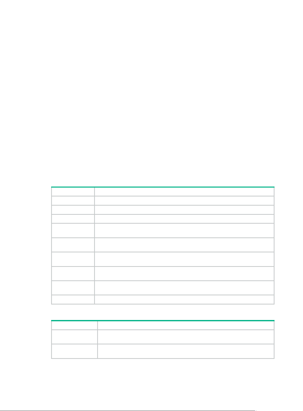
Symbols
Convention Description
WARNING!
An alert that calls attention to important information that if not understood or followed
can result in personal injury.
CAUTION:
IMPORTANT:
NOTE:
TIP:
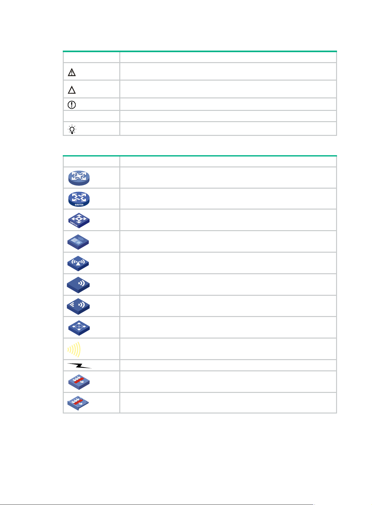
Network topology icons
Convention Description
An alert that calls attention to important information that if not understood or followed
can result in data loss, data corruption, or damage to hardware or software.
An alert that calls attention to essential information.
An alert that contains additional or supplementary information.
An alert that provides helpful information.
Represents a generic network device, such as a router, switch, or firewall.
Represents a routing-capable device, such as a router or Layer 3 switch.
Represents a generic switch, such as a Layer 2 or Layer 3 switch, or a router that
supports Layer 2 forwarding and other Layer 2 features.
Represents an access controller, a unified wired-WLAN module, or the access
controller engine on a unified wired-WLAN switch.
Represents an access point.
T
T
T
T
Represents a wireless terminator unit.
Represents a wireless terminator.
Represents a mesh access point.
Represents omnidirectional signals.
Represents directional signals.
Represents a security product, such as a firewall, UTM, multiservice security
gateway, or load balancing device.
Represents a security module, such as a firewall, load balancing, NetStream, SSL
VPN, IPS, or ACG module.
Examples provided in this document
Examples in this document might use devices that differ from your device in hardware model,
configuration, or software version. It is normal that the port numbers, sample output, screenshots,
and other information in the examples differ from what you have on your device.
Page 5

Documentation feedback
You can e-mail your comments about product documentation to info@h3c.com.
We appreciate your comments.
Page 6

Contents
1 Safety information ······································································· 1-1
Safety sign conventions ············································································································ 1-1
Power source recommendations ································································································ 1-2
Installation safety recommendations ··························································································· 1-2
General operating safety ···································································································· 1-2
Electrical safety ················································································································ 1-2
Rack mounting recommendations ························································································ 1-2
ESD prevention ················································································································ 1-3
Cooling performance ········································································································· 1-3
Battery safety ·················································································································· 1-4
2 Preparing for installation ······························································· 2-1
Rack requirements ·················································································································· 2-1
Installation site requirements ····································································································· 2-3
Airflow directions ·············································································································· 2-3
Temperature, humidity, and altitude requirements ··································································· 2-3
Cleanliness requirements ··································································································· 2-3
Grounding requirements ···································································································· 2-4
Installation tools ······················································································································ 2-4
3 Installing or removing the server ···················································· 3-1
Installing the server ················································································································· 3-1
Installing rails ·················································································································· 3-1
Rack-mounting the server ·································································································· 3-1
(Optional) Installing the CMA ······························································································ 3-2
Connecting external cables ······································································································· 3-2
Cabling guidelines ············································································································ 3-2
Connecting a mouse, keyboard, and monitor ·········································································· 3-2
Connecting an Ethernet cable ····························································································· 3-4
Connecting the power cord ································································································· 3-5
Securing cables ··············································································································· 3-7
Removing the server from a rack ································································································ 3-8
4 Powering on and powering off the server ········································· 4-1
Important information ··············································································································· 4-1
Powering on the server ············································································································ 4-1
Prerequisites ··················································································································· 4-1
Procedure ······················································································································· 4-1
Powering off the server ············································································································ 4-2
Prerequisites ··················································································································· 4-2
Procedure ······················································································································· 4-2
5 Configuring the server ································································· 5-1
Configuration flowchart············································································································· 5-1
Powering on the server ············································································································ 5-1
Configuring basic BIOS settings ································································································· 5-2
Setting the server boot order ······························································································· 5-2
Setting the BIOS passwords ······························································································· 5-2
Configuring RAID ···················································································································· 5-2
Installing the operating system and hardware drivers ······································································ 5-2
Installing the operating system ···························································································· 5-2
Installing hardware drivers ·································································································· 5-2
Updating firmware ··················································································································· 5-3
6 Installing and removing hardware options ········································ 6-1
General guidelines ·················································································································· 6-1
General prerequisites··············································································································· 6-1
i
Page 7

Replacing the security bezel ······································································································ 6-1
Removing the security bezel ······························································································· 6-1
Installing the security bezel ································································································· 6-1
Installing the diagnostic panel ···································································································· 6-2
Replacing the diagnostic panel ·································································································· 6-2
Installing front drive cages ········································································································ 6-3
Prerequisites ··················································································································· 6-3
Procedure ······················································································································· 6-3
Installing the rear 2SFF UniBay drive cage ··················································································· 6-4
Replacing a SAS/SATA drive ····································································································· 6-5
Guidelines ······················································································································ 6-5
Prerequisites ··················································································································· 6-5
Removing a SAS/SATA drive ······························································································ 6-5
Installing a SAS/SATA drive ······························································································· 6-5
Verifying the replacement ··································································································· 6-5
Replacing an NVMe drive ········································································································· 6-6
Guidelines ······················································································································ 6-6
Prerequisites ··················································································································· 6-6
Procedure ······················································································································· 6-6
Verifying the replacement ··································································································· 6-6
Replacing the NVMe VROC module ···························································································· 6-7
Removing the NVMe VROC module ····················································································· 6-7
Installing the NVMe VROC module······················································································· 6-7
Replacing a power supply ········································································································· 6-7
Guidelines ······················································································································ 6-7
Removing a power supply ·································································································· 6-8
Installing a power supply ···································································································· 6-8
Replacing riser cards and PCIe modules ······················································································ 6-8
Guidelines ······················································································································ 6-8
Removing a riser card and a PCIe module ············································································· 6-9
Installing a riser card and a PCIe module on PCIe riser connector 1 or 2 ······································ 6-9
Installing PCIe modules and a riser card on PCIe riser connector 3 ············································· 6-9
Replacing a SATA M.2 SSD ···································································································· 6-10
Guidelines ···················································································································· 6-10
Removing a SATA M.2 SSD ····························································································· 6-10
Installing a SATA M.2 SSD ······························································································· 6-11
Replacing the M.2 transfer module ··························································································· 6-11
Removing the M.2 transfer module ····················································································· 6-11
Installing the M.2 transfer module ······················································································ 6-11
Replacing an SD card ············································································································ 6-12
Guidelines ···················································································································· 6-12
Removing an SD card ····································································································· 6-12
Installing an SD card ······································································································· 6-12
Replacing the dual SD card extended module ············································································· 6-13
Removing the dual SD card extended module ······································································ 6-13
Installing the dual SD card extended module ········································································ 6-13
Replacing a standard storage controller and a power fail safeguard module ······································ 6-13
Guidelines ···················································································································· 6-14
Preparing for replacement ································································································ 6-15
Removing a standard storage controller and a power fail safeguard module ································ 6-15
Installing a storage controller and a power fail safeguard module ·············································· 6-15
Replacing a GPU module ······································································································· 6-17
Guidelines ···················································································································· 6-17
Removing a GPU module ································································································· 6-17
Installing a GPU module ·································································································· 6-17
Replacing an Ethernet adapter ································································································· 6-18
Guidelines ···················································································································· 6-18
Replacing the sLOM Ethernet adapter ················································································ 6-18
Replacing a standard PCIe Ethernet adapter ········································································ 6-18
Replacing a drive backplane ···································································································· 6-19
Removing a drive backplane ····························································································· 6-19
Installing a drive backplane ······························································································ 6-19
ii
Page 8

Replacing the processor mezzanine board ················································································· 6-19
Removing the processor mezzanine board ·········································································· 6-19
Installing the processor mezzanine board ············································································ 6-20
Replacing a DIMM················································································································· 6-20
Guidelines ···················································································································· 6-20
Removing a DIMM ·········································································································· 6-23
Installing a DIMM ··········································································································· 6-24
Replacing a processor ··········································································································· 6-24
Guidelines ···················································································································· 6-24
Removing a processor ····································································································· 6-25
Installing a processor ······································································································ 6-25
Verifying the replacement ································································································· 6-26
Installing and setting up a TCM or TPM ····················································································· 6-27
Installation and setup flowchart ························································································· 6-27
Installing a TCM or TPM ·································································································· 6-27
Enabling the TCM or TPM in the BIOS ················································································ 6-28
Configuring encryption in the operating system ····································································· 6-29
Replacing the system battery ··································································································· 6-29
Removing the system battery ···························································································· 6-29
Installing the system battery ····························································································· 6-29
Replacing the system board ···································································································· 6-30
Guidelines ···················································································································· 6-30
Removing the system board ····························································································· 6-30
Installing the system board ······························································································· 6-31
7 Connecting internal cables ···························································· 7-1
Guidelines ····························································································································· 7-1
Connecting drive cables for 8SFF SAS/SATA server ·············································································· 7-1
Front 16SFF SAS/SATA drive cabling ··················································································· 7-1
Front 24SFF SAS/SATA drive cabling ··················································································· 7-4
Front hybrid 16SFF SAS/SATA and 8SFF UniBay drive cabling ················································· 7-8
Connecting drive cables for 8SFF UniBay server ········································································· 7-12
Front hybrid 4SFF UniBay and 4SFF SAS/SATA drive cabling ················································· 7-12
Front 8SFF UniBay drive cabling ······················································································· 7-16
Front 16SFF UniBay drive cabling ······················································································ 7-19
Front hybrid 8SFF SAS/SATA and 16SFF UniBay drive cabling ··············································· 7-23
Connecting drive cables for the rear 2SFF UniBay drives ······························································ 7-27
Connecting the NVMe data cable ······················································································· 7-27
Connecting the SATA data cable ······················································································· 7-29
Connecting the AUX signal cable and the power cord ···························································· 7-29
Connecting the SATA M.2 SSD cable ························································································ 7-29
8 Maintenance ·············································································· 8-1
Guidelines ····························································································································· 8-1
Maintenance tools ··················································································································· 8-1
Maintenance tasks ·················································································································· 8-1
Observing LED status ······································································································· 8-1
Monitoring the temperature and humidity in the equipment room ················································ 8-1
Examining cable connections ······························································································ 8-2
Technical support ··················································································································· 8-2
9 Appendix A Server specifications ·················································· 9-1
Server models and chassis view ································································································ 9-1
Technical specifications ············································································································ 9-2
Components ·························································································································· 9-3
Front panel ···························································································································· 9-4
Front panel view ··············································································································· 9-4
LEDs and buttons ············································································································· 9-5
Ports······························································································································ 9-6
Rear panel ···························································································································· 9-7
Rear panel view ··············································································································· 9-7
LEDs ····························································································································· 9-7
iii
Page 9

Ports······························································································································ 9-8
System board ························································································································· 9-9
System board components ································································································· 9-9
System maintenance switches ·························································································· 9-10
Processor mezzanine board ····························································································· 9-11
DIMM slots ···················································································································· 9-12
10 Appendix B Component specifications ············································ 10-1
About component model names ······························································································· 10-1
Processors ·························································································································· 10-1
Skylake processors ········································································································· 10-1
Cascade Lake processors ································································································ 10-1
Jintide-C series processors ······························································································ 10-2
DIMMs ································································································································ 10-2
DRAM specifications ······································································································· 10-2
DCPMM specifications ···································································································· 10-2
DRAM DIMM rank classification label ················································································· 10-3
HDDs and SSDs ··················································································································· 10-3
Drive specifications ········································································································· 10-3
Drive LEDs ··················································································································· 10-5
Drive configurations and numbering ··················································································· 10-7
PCIe modules ······················································································································ 10-9
Storage controllers ········································································································· 10-9
GPU modules ··············································································································· 10-15
PCIe Ethernet adapters ·································································································· 10-15
FC HBAs ····················································································································· 10-16
sLOM Ethernet adapters ········································································································ 10-17
Riser cards ························································································································· 10-18
Riser card guidelines ······································································································ 10-18
RC-2*FHHL-G3 ············································································································· 10-18
RC-3*FHHL-G3 ············································································································· 10-19
RC-4*NVME-3*FHHL-G3 ································································································ 10-20
RC-8*NVME-1*FHHL-G3 ································································································ 10-21
Fans ································································································································· 10-22
Fan layout ···················································································································· 10-22
Power supplies ···················································································································· 10-23
800 W Platinum power supply ·························································································· 10-23
800 W 336 V high-voltage power supply ············································································· 10-23
850 W Titanium power supply ·························································································· 10-24
1200 W Platinum power supply ························································································ 10-24
1600 W power supply ····································································································· 10-25
Expander modules ··············································································································· 10-25
Diagnostic panels················································································································· 10-25
Diagnostic panel specifications ························································································· 10-26
Diagnostic panel view ····································································································· 10-26
LEDs ·························································································································· 10-26
Fiber transceiver modules ······································································································ 10-30
Storage options other than HDDs and SDDs ·············································································· 10-30
NVMe VROC modules ·········································································································· 10-30
TPM/TCM modules ·············································································································· 10-30
Security bezels, slide rail kits, and cable management brackets ····················································· 10-31
11 Appendix C Hot removal and managed hot removal of NVMe drives · 11-1
Feature and operating system compatibility ················································································ 11-1
Performing a managed hot removal in Windows ·········································································· 11-2
Prerequisites ················································································································· 11-2
Procedure ····················································································································· 11-2
Performing a managed hot removal in Linux ··············································································· 11-3
Prerequisites ················································································································· 11-3
Performing a managed hot removal from the CLI ·································································· 11-3
iv
Page 10

12 Appendix D Environment requirements ······································· 12-1
About environment requirements ······························································································ 12-1
General environment requirements ··························································································· 12-1
Operating temperature requirements ························································································· 12-1
General guidelines ·········································································································· 12-1
8SFF or 16SFF front drive configuration ·············································································· 12-2
24SFF front drive configuration ························································································· 12-2
13 Appendix E Product recycling ··················································· 13-1
14 Appendix F Glossary ······························································· 14-1
15 Appendix G Acronyms ····························································· 15-1
v
Page 11

1 Safety information
Safety sign conventions
To avoid bodily injury or damage to the server or its components, make sure you are familiar with the
safety signs on the server chassis or its components.
Table 1-1 Safety signs
Sign Description
Circuit or electricity hazards are present. Only H3C authorized or professional
server engineers are allowed to service, repair, or upgrade the server.
WARNING!
To avoid bodily injury or damage to circuits, do not open any components marked
with the electrical hazard sign unless you have authorization to do so.
Electrical hazards are present. Field servicing or repair is not allowed.
WARNING!
To avoid bodily injury, do not open any components with the field-servicing
forbidden sign in any circumstances.
The RJ-45 port is used for network connection.
WARNING!
To avoid electrical shock, fire, or damage to hardware, do not connect a telephone
or any other communication equipment to this port.
The surface or component might be hot and present burn hazards.
WARNING!
To avoid being burnt, allow hot surfaces or components to cool before touching
them.
The server or component is heavy and requires more than one people to carry or
move.
WARNING!
To avoid bodily injury or damage to hardware, do not move a heavy component
alone. In addition, observe local occupational health and safety requirements and
guidelines for manual material handling.
The server is powered by multiple power supplies.
WARNING!
To avoid bodily injury from electrical shocks, make sure you disconnect all power
supplies if you are performing offline servicing.
1-1
Page 12

Power source recommendations
Power instability or outage might cause data loss, service disruption, or damage to the server in the
worst case.
To protect the server from unstable power or power outage, use uninterrupted power supplies (UPSs)
to provide power for the server.
Installation safety recommendations
To avoid bodily injury or damage to the server, read the following information carefully before you
operate the server.
General operating safety
To avoid bodily injury or damage to the server, follow these guidelines when you operate the server:
• Only H3C authorized or professional server engineers are allowed to install, service, repair,
operate, or upgrade the server.
• Make sure all cables are correctly connected before you power on the server.
• Place the server on a clean, stable table or floor for servicing.
• To avoid being burnt, allow the server and its internal modules to cool before touching them.
Electrical safety
WARNING!
If you put the server in standby mode (system power LED in amber) with the power on/standby
button on the front panel, the power supplies continue to supply power to some circuits in the server.
To remove all power for servicing safety, you must first press the button until the system power LED
turns into steady amber, and then remove all power cords from the server.
To avoid bodily injury or damage to the server, follow these guidelines:
• Always use the power cords that came with the server.
• Do not use the power cords that came with the server for any other devices.
• Power off the server when installing or removing any components that are not hot swappable.
Rack mounting recommendations
To avoid bodily injury or damage to the equipment, follow these guidelines when you rack mount a
server:
• Mount the server in a standard 19-inch rack.
• Make sure the leveling jacks are extended to the floor and the full weight of the rack rests on the
leveling jacks.
• Couple the racks together in multi-rack installations.
• Load the rack from the bottom to the top, with the heaviest hardware unit at the bottom of the
rack.
1-2
Page 13

• Get help to lift and stabilize the server during installation or removal, especially when the server
is not fastened to the rails. As a best practice, a minimum of two people are required to safely
load or unload a rack. A third person might be required to help align the server if the server is
installed higher than check level.
• For rack stability, make sure only one unit is extended at a time. A rack might get unstable if
more than one server unit is extended.
• Make sure the rack is stable when you operate a server in the rack.
• To maintain correct airflow and avoid thermal damage to the server, use blanks to fill empty rack
units.
ESD prevention
Electrostatic charges that build up on people and tools might damage or shorten the lifespan of the
system board and electrostatic-sensitive components.
Preventing electrostatic discharge
To prevent electrostatic damage, follow these guidelines:
• Transport or store the server with the components in antistatic bags.
• Keep the electrostatic-sensitive components in the antistatic bags until they arrive at an
ESD-protected area.
• Place the components on a grounded surface before removing them from their antistatic bags.
• Avoid touching pins, leads, or circuitry.
• Make sure you are reliably grounded when touching an electrostatic-sensitive component or
assembly.
Grounding methods to prevent electrostatic discharge
The following are grounding methods that you can use to prevent electrostatic discharge:
• Wear an ESD wrist strap and make sure it makes good skin contact and is reliably grounded.
• Take adequate personal grounding measures, including wearing antistatic clothing, static
dissipative shoes, and antistatic gloves.
• Use conductive field service tools.
• Use a portable field service kit with a folding static-dissipating work mat.
Cooling performance
Poor cooling performance might result from improper airflow and poor ventilation and might cause
damage to the server.
To ensure good ventilation and proper airflow, follow these guidelines:
• Install blanks over empty module slots, including drive slots, rear PCIe slots, and power supply
slots.
• Do not block the ventilation openings in the server chassis.
• To avoid thermal damage to the server, do not operate the server for long periods in any of the
following conditions:
{ Access panel open or uninstalled.
{ Air baffles uninstalled.
{ PCIe slots, drive slots, or power supply slots empty.
• If the server is stacked in a rack with other devices, make sure there is a minimum clearance of
2 mm (0.08 in) below and above the server.
1-3
Page 14

Battery safety
The server's system board contains a system battery, which is designed with a lifespan of 5 to 10
years.
If the server no longer automatically displays the correct date and time, you might need to replace
the battery. When you replace the battery, follow these safety guidelines:
• Do not attempt to recharge the battery.
• Do not expose the battery to a temperature higher than 60°C (140°F).
• Do not disassemble, crush, puncture, short external contacts, or dispose of the battery in fire or
water.
• Dispose of the battery at a designated facility. Do not throw the battery away together with other
wastes.
1-4
Page 15

2 Preparing for installation
Prepare a rack that meets the rack requirements and plan an installation site that meets the
requirements of space and airflow, temperature, humidity, equipment room height, cleanliness, and
grounding.
Rack requirements
IMPORTANT:
As a best practice to avoid affecting the server chassis, install power distribution units (PDUs) with
the outputs facing backwards. If you install PDUs with the outputs facing the inside of the server,
please perform an onsite survey to make sure the cables won't affect the server rear.
The server is 2U high. The rack for installing the server must meet the following requirements:
• A standard 19-inch rack.
• A clearance of more than 50 mm (1.97 in) between the rack front posts and the front rack door.
• A minimum of 1200 mm (47.24 in) in depth as a best practice.
The installation limits for a rack vary by rack depth. For more information, see Table 2-1. As
best practice to avoid potential issues, contact H3C support for on-site surveys.
a
Table 2-1 Installation limits for different rack depths
Rack depth Installation limits
• The H3C cable management arm (CMA) is not supported.
• A clearance of 60 mm (2.36 in) is reserved from the server rear to the rear rack
1000 mm
(39.37 in)
1100 mm
(43.31 in)
1200 mm
(47.24 in)
door for cabling.
• The slide rails and PDUs might hinder each other. As a best practice, contact
H3C Support to determine the installation site of PDUs or change PDU size. If the
slide rails cannot be installed, use trays or other tools to support the server.
Make sure the CMA does not hinder PDUs at the server rear before installing the H3C
CMA. If the CMA hinders PDU installation, change a rack with larger depth or adjust
the installation site of PDUs.
Make sure the CMA does not hinder PDUs or the cabling. If the CMA hinders PDU
installation or cabling, change the installation site of PDUs.
For detailed installation suggestions, see Figure 2-1.
2-1
Page 16

Figure 2-1 Installation suggestions for a 1200 mm deep rack (top view)
(1) Rack depth 1200 mm (47.24 in)
(2) More than 50 mm (1.97 in) between the rack front posts and the front rack door
(3) 780 mm (30.71 in) between the rack front posts and the rear of the chassis, with handles of the
power supplies not shown
(4) Server depth with chassis ears, 800 mm (31.50 in)
(5) 960 mm (37.80 in) between the front rack posts and CMA
(6) 860 mm (33.86 in) between the front rack posts and the rear of the slide rails
2-2
Page 17

Installation site requirements
Airflow directions
Figure 2-2 Airflow through the server
(1) to (4) Directions of the airflow into the chassis and power supplies
(5) Direction of the airflow out of the power supplies (6) to (8) Directions of the airflow out of the chassis
Temperature, humidity, and altitude requirements
To ensure correct operation of the server, make sure the room temperature, humidity, and altitude
meet the requirements as described in "Appendix C Environment requirements."
Cleanliness requirements
Mechanically active substances buildup on the chassis might result in electrostatic adsorption, which
causes poor contact of metal components and contact points. In the worst case, electrostatic
adsorption can cause communication failure.
Table 2-2 Mechanically active substance concentration limit in the equipment room
Substance Particle diameter Concentration limit
Dust particles ≥ 5 µm
Dust (suspension) ≤ 75 µm ≤ 0.2 mg/m3
≤ 3 × 10⁴ particles/m3
(No visible dust on desk in three days)
Dust
(sedimentation)
Sand ≥ 150 µm ≤ 30 mg/m3
75 µm to 150 µm ≤ 1.5 mg/(m
2-3
2
h)
Page 18

The equipment room must also meet limits on salts, acids, and sulfides to eliminate corrosion and
premature aging of components, as shown in Table 2-3.
Table 2-3
Harmful gas limits in an equipment room
Gas Maximum concentration (mg/m
SO2 0.2
H2S 0.006
NO2 0.04
NH
3
Cl
2
Grounding requirements
Correctly connecting the server grounding cable is crucial to lightning protection, anti-interference,
and ESD prevention. The server can be grounded through the grounding wire of the power supply
system and no external grounding cable is required.
Installation tools
Table 2-4 lists the tools that you might use during installation.
Table 2-4 Installation tools
0.05
0.01
3
)
Picture Name Description
T25 Torx screwdriver For captive screws inside chassis ears.
T30 Torx screwdriver For captive screws on processor heatsinks.
T15 Torx screwdriver
(shipped with the server)
T10 Torx screwdriver
(shipped with the server)
Flat-head screwdriver For replacing the system battery.
Phillips screwdriver For screws on drive brackets.
Cage nut insertion/extraction
tool
Diagonal pliers For clipping insulating sleeves.
Tape measure For distance measurement.
For screws on the system board.
For screws on riser cards.
For insertion and extraction of cage nuts in rack posts.
2-4
Page 19

Picture Name Description
Multimeter For resistance and voltage measurement.
ESD wrist strap For ESD prevention when you operate the server.
Antistatic gloves For ESD prevention when you operate the server.
Antistatic clothing For ESD prevention when you operate the server.
Ladder For high-place operations.
Interface cable (such as an
Ethernet cable or optical
For connecting the server to an external network.
fiber)
Monitor For displaying the output from the server.
2-5
Page 20

3 Installing or removing the server
Installing the server
As a best practice, install hardware options to the server (if needed) before installing the server in the
rack. For more information about how to install hardware options, see "Installing and removing
ware options."
hard
Installing rails
Install the inner rails and the outer rails in the rack mounting rail kit to the server and the rack,
respectively. For information about installing the rails, see the document shipped with the rails.
Rack-mounting the server
1. Slide the server into the rack. For more information about how to slide the server into the rack,
see the document shipped with the rails.
Figure 3-1 Rack-mounting the server
2. Secure the server as shown in Figure 3-2:
a. Push the server until the chassis ears are flush against the rack front posts, as shown by
callout 1.
b. Unlock the latches of the chassis ears, as shown by callout 2.
c. Fasten the captive screws inside the chassis ears and lock the latches, as shown by callout
3.
3-1
Page 21

Figure 3-2 Securing the server
(Optional) Installing the CMA
Install the CMA if the server is shipped with a CMA. For information about how to install the CMA, see
the installation guide shipped with the CMA.
Connecting external cables
Cabling guidelines
WARNING!
To avoid electric shock, fire, or damage to the equipment, do not connect communication equipment
to RJ-45 Ethernet ports on the server.
• For heat dissipation, make sure no cables block the inlet or outlet air vents of the server.
• To easily identify ports and connect/disconnect cables, make sure the cables do not cross.
• Label the cables for easy identification of the cables.
• Wrap unused cables onto an appropriate position on the rack.
• To avoid damage to cables when extending the server out of the rack, do not route the cables
too tight if you use the CMA.
Connecting a mouse, keyboard, and monitor
About this task
Perform this task before you configure the BIOS, HDM, FIST, or RAID on the server or enter the
operating system of the server.
The server provides two VGA connectors for connecting a monitor, one on the front panel and one on
the rear panel.
3-2
Page 22

The server is not shipped with a standard PS2 mouse and keyboard. To connect a PS2 mouse and
keyboard, you must prepare a USB-to-PS2 adapter.
Procedure
1. Connect one plug of a VGA cable to a VGA connector on the server, and fasten the screws on
the plug.
Figure 3-3 Connecting a VGA cable
2. Connect the other plug of the VGA cable to the VGA connector on the monitor, and fasten the
screws on the plug.
3. Connect the mouse and keyboard.
{ For a USB mouse and keyboard, directly connect the USB connectors of the mouse and
keyboard to the USB connectors on the server.
{ For a PS2 mouse and keyboard, insert the USB connector of the USB-to-PS2 adapter to a
USB connector on the server. Then, insert the PS2 connectors of the mouse and keyboard
into the PS2 receptacles of the adapter.
Figure 3-4 Connecting a PS2 mouse and keyboard by using a USB-to-PS2 adapter
3-3
Page 23

Connecting an Ethernet cable
About this task
Perform this task before you set up a network environment or log in to the HDM management
interface through the HDM network port to manage the server.
Procedure
1. Determine the network port on the server.
{ To connect the server to the external network, use the Ethernet port on the Ethernet
adapter.
{ To log in to the HDM management interface, use either of the following HDM network ports:
− HDM dedicated network port on the server. For the position of the HDM dedicated
network port, see "Rear panel view."
− HDM shared network port on the sLOM Ethernet adapter (if any). For the position of the
HDM shared network port, see "Replacing the sLOM Ethernet adapter."
2. Determine the type of the Ethernet cable.
Verify the connectivity of the cable by using a link tester.
If you are replacing the Ethernet cable, make sure the new cable is of the same type with the old
cable or compatible with the old cable.
3. Label the Ethernet cable by filling in the names and numbers of the server and the peer device
on the label.
As a best practice, use labels of the same kind for all cables.
If you are replacing the Ethernet cable, label the new cable with the same number as the
number of the old cable.
4. Connect one end of the Ethernet cable to the network port on the server and the other end to
the peer device.
Figure 3-5 Connecting an Ethernet cable
5. Verify network connectivity.
After powering on the server, use the
ping command to test the network connectivity. If the
connection between the server and the peer device fails, make sure the Ethernet cable is
correctly connected.
3-4
Page 24

6. Secure the Ethernet cable. For information about how to secure cables, see "Securing cables."
Connecting the power cord
Guidelines
WARNING!
To avoid damage to the equipment or even bodily injury, use the power cord that ships with the
server.
Before connecting the power cord, make sure the server and components are installed correctly.
Procedure
1. Insert the power cord plug into the power receptacle of a power supply at the rear panel, as
shown in Figure 3-6.
Figure 3-6
Connecting the power cord
2. Connect the other end of the power cord to the power source, for example, the power strip on
the rack.
3. Secure the power cord to avoid unexpected disconnection of the power cord.
a. (Optional.) If the cable clamp is positioned too near the power cord that it blocks the power
cord plug connection, press down the tab on the cable mount and slide the clip backward.
3-5
Page 25

Figure 3-7 Sliding the cable clamp backward
b. Open the cable clamp, place the power cord through the opening in the cable clamp, and
then close the cable clamp, as shown by callouts 1, 2, 3, and 4 in Figure 3-8.
Figure 3-8
Securing the power cord
c. Slide the cable clamp forward until it is flush against the edge of the power cord plug, as
shown in Figure 3-9.
3-6
Page 26

Figure 3-9 Sliding the cable clamp forward
Securing cables
Securing cables to the CMA
For information about how to secure cables to the CMA, see the installation guide shipped with the
CMA.
Securing cables to slide rails by using cable straps
You can secure cables to either left slide rails or right slide rails. As a best practice for cable
management, secure cables to left slide rails.
When multiple cable straps are used in the same rack, stagger the strap location, so that the straps
are adjacent to each other when viewed from top to bottom. This positioning will enable the slide rails
to slide easily in and out of the rack.
To secure cables to slide rails by using cable straps:
1. Hold the cables against a slide rail.
2. Wrap the strap around the slide rail and loop the end of the cable strap through the buckle.
3. Dress the cable strap to ensure that the extra length and buckle part of the strap are facing
outside of the slide rail.
3-7
Page 27

Figure 3-10 Securing cables to a slide rail
Removing the server from a rack
1. Power down the server. For more information, see "Powering off the server."
2. Disconnect all peripheral cables from the server.
3. Extend the server from the rack, as shown in Figure 3-11.
a. Open the lat
b. Loosen the captive screws.
c. Slide the server out of the rack.
Figure 3-11 Extending the server from the rack
ches of the chassis ears.
4. Place the server on a clean, stable surface.
3-8
Page 28

4 Powering on and powering off the
server
Important information
If the server is connected to external storage devices, make sure the server is the first device to
power off and then the last device to power on. This restriction prevents the server from mistakenly
identifying the external storage devices as faulty devices.
Powering on the server
Prerequisites
Before you power on the server, you must complete the following tasks:
• Install the server and internal components correctly.
• Connect the server to a power source.
Procedure
Powering on the server by pressing the power on/standby button
Press the power on/standby button to power on the server.
The server exits standby mode and supplies power to the system. The system power LED changes
from steady amber to flashing green and then to steady green. For information about the position of
the system power LED, see "LEDs and buttons."
Powering on the server from the HDM Web interface
1. Log in to the HDM.
For information about how to log in to HDM, see the firmware update guide for the server.
2. In the navigation pane, select Power & Thermal > Power Control.
The power control configuration page opens.
3. Select Power on and then click Execute.
Powering on the server from the remote console interface
1. Log in to HDM.
For information about how to log in to HDM, see the firmware update guide for the server.
2. Log in to a remote console and then power on the server.
For information about how to log in to a remote console, see HDM online help.
Configuring automatic power-on
You can configure automatic power-on from HDM or the BIOS.
To configure automatic power-on from HDM:
1. Log in to HDM.
For information about how to log in to HDM, see the firmware update guide for the server.
4-1
Page 29

2. In the navigation pane, select Power & Thermal > Power Control.
The meter power configuration page opens.
3. Click the Automatic power-on tab and then select Always power on.
4. Click Save.
To configure automatic power-on from the BIOS:
1. Enter the BIOS.
For information about how to enter the BIOS, see the BIOS user guide for the server.
2. Select Server Mgmt, > AC Restore Settings, and then press Enter.
3. Select Always Power On, and then press Enter.
4. Press F4 to save the configuration.
Powering off the server
Prerequisites
Before powering off the server, you must complete the following tasks:
• Backup all critical data.
• Make sure all services have stopped or have been migrated to other servers.
Procedure
Powering off the server from its operating system
1. Connect a monitor, mouse, and keyboard to the server.
2. Shut down the operating system of the server.
3. Disconnect all power cords from the server.
Powering off the server by pressing the power on/standby button
1. Press the power on/standby button and wait for the system power LED to turn into steady
amber.
2. Disconnect all power cords from the server.
Powering off the server forcedly by pressing the power on/standby button
IMPORTANT:
This method forces the server to enter standby mode without properly exiting applications and the
operating system. Use this method only when the server system crashes. For example, a process
gets stuck.
1. Press and hold the power on/standby button until the system power LED turns into steady
amber.
2. Disconnect all power cords from the server.
Powering off the server from the HDM Web interface
1. Log in to HDM.
For information about how to log in to HDM, see the firmware update guide for the server.
2. In the navigation pane, select Power & Thermal > Power Control.
The power control configuration page opens.
4-2
Page 30

3. Select Force power-off or Graceful power-off and then click Execute to put the server in
standby mode.
4. Disconnect all power cords from the server.
Powering off the server from the remote console interface
1. Log in to HDM.
For information about how to log in to HDM, see the firmware update guide for the server.
2. Log in to a remote console and then power off the server.
For information about how to log in to a remote console, see HDM online help.
3. Disconnect all power cords from the server.
4-3
Page 31

5 Configuring the server
The following information describes the procedures to configure the server after the server
installation is complete.
Configuration flowchart
Figure 5-1 Configuration flowchart
Powering on the server
1. Power on the server. For information about the procedures, see "Powering on the server."
2. Verify that the health LED on the front panel is steady green, which indicates that the system is
operating correctly. For more information about the health LED status, see "LEDs and buttons."
5-1
Page 32

Configuring basic BIOS settings
You can set the server boot order and the BIOS user and administrator passwords from the BIOS
setup utility of the server.
NOTE:
The BIOS menu screenshots used in this document are for illustration only and might differ from
your products.
Setting the server boot order
You can change the server boot order from the BIOS. For information about the default boot order
and the order change method, see the BIOS user guide for the server.
Setting the BIOS passwords
By default, no BIOS user password or BIOS administrator password is set. All people have full
access to the BIOS.
To prevent unauthorized access to the BIOS settings, set BIOS administrator and user passwords.
To perform access control based on user roles, make sure the BIOS user password and the BIOS
administrator password are different.
For more information about setting passwords and privileges for the BIOS user and administrator,
see the BIOS user guide for the server.
Configuring RAID
Configure physical and logical drives (RAID arrays) for the server.
The supported RAID levels and RAID configuration methods vary by storage controller model. For
more information, see the storage controller user guide for the server.
Installing the operating system and hardware drivers
Installing the operating system
Install a compatible operating system on the server by following the procedures described in the
operating system installation guide for the server.
For information about the operating system compatibility, visit the OS compatibility query tool
at http://www.h3c.com/cn/Service/Document_Softwa
re/Document_Center/Server/.
Installing hardware drivers
IMPORTANT:
In case an update failure causes hardware unavailability, always back up the drivers before you
update them.
5-2
 Loading...