

Page 1

New H3C Technologies Co., Ltd.
http://www.h3c.com
Document version: 5W101-20190131
H3C UIS-Cell 3000 G3 Hyper-
Converged Infrastructure
User Guide
Page 2

Copyright © 2019, New H3C Technologies Co., Ltd. and its licensors
All rights reserved
No part of this manual may be reproduced or transmitted in any form or by any means without prior written
consent of New H3C Technologies Co., Ltd.
Trademarks
Except for the trademarks of New H3C Technologies Co., Ltd., any trademarks that may be mentioned in this
document are the property of their respective owners.
Notice
The information in this document is subject to change without notice. All contents in this document, including
statements, information, and recommendations, are believed to be accurate, but they are presented without
warranty of any kind, express or implied. H3C shall not be liable for technical or editorial errors or omissions
contained herein.
Environmental protection
This product has been designed to comply with the environmental protection requirements. The storage, use,
and disposal of this product must meet the applicable national laws and regulations.
Page 3
Preface
This user guide describes the installation, hardware replacement, cabling, software configuration,
and maintenance of the UIS-Cell 3000 G3, as well as UIS Manager login and license registration.
This preface includes the following topics about the documentation:
• Audience.
• Conventions.
• Documentation feedback.
Audience
This documentation is intended for:
• Network planners.
• Field technical support and servicing engineers.
• Network administrators working with the server series.
Conventions
The following information describes the conventions used in the documentation.
GUI conventions
Convention Description
Boldface
>
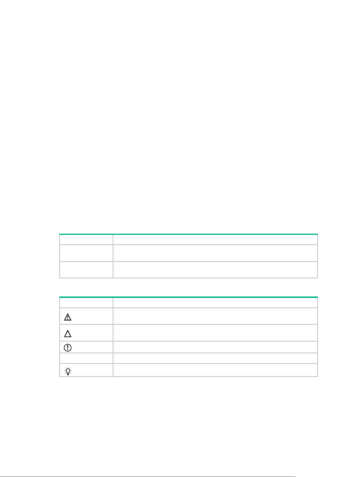
Symbols
Convention Description
WARNING!
CAUTION:
IMPORTANT:
NOTE:
TIP:
Window names, button names, field names, and menu items are in Boldface. For
.
New User
window opens; click OK.
File
>
Create
>
example, the
Multi-level menus are separated by angle brackets. For example,
Folder
An alert that calls attention to important information that if not understood or followed
can result in personal injury.
An alert that calls attention to important information that if not understood or followed
can result in data loss, data corruption, or damage to hardware or software.
An alert that calls attention to essential information.
An alert that contains additional or supplementary information.
An alert that provides helpful information.
Documentation feedback
You can e-mail your comments about product documentation to info@h3c.com.
We appreciate your comments.
Page 4

Contents
Safety information ············································································ 1
Safety sign conventions ··············································································································· 1
Power source recommendations ··································································································· 1
Installation safety recommendations ······························································································ 2
General operating safety ······································································································· 2
Electrical safety ··················································································································· 2
Rack mounting recommendations ··························································································· 2
ESD prevention ··················································································································· 3
Cooling performance ············································································································ 3
Battery safety ····················································································································· 3
Preparing for installation ···································································· 5
Installation site requirements ········································································································ 5
Space and airflow requirements ····························································································· 5
Temperature, humidity, and altitude requirements ······································································ 5
Cleanliness requirements ······································································································ 5
Grounding requirements ······································································································· 6
Installation tools ························································································································· 6
Installing or removing the server ·························································· 8
Installing the server ···················································································································· 8
Installing rails ····················································································································· 8
Rack-mounting the server ····································································································· 8
(Optional) Installing cable management brackets ······································································· 9
Connecting external cables ·········································································································· 9
Cabling guidelines ··············································································································· 9
Connecting a mouse, keyboard, and monitor ············································································· 9
Connecting an Ethernet cable ······························································································ 11
Connecting a USB device ··································································································· 12
Connecting the power cord ·································································································· 13
Securing cables ················································································································ 15
Removing the server from a rack ································································································· 16
Powering on and powering off the server ············································· 18
Important information ················································································································ 18
Powering on the server ············································································································· 18
Prerequisites ···················································································································· 18
Procedure ························································································································ 18
Powering off the server ············································································································· 19
Guidelines ······················································································································· 19
Procedure ························································································································ 19
Configuring the server ····································································· 20
Powering on the server ············································································································· 20
Updating firmware ···················································································································· 20
Accessing the UIS Manager ····························································· 21
Preparing for the access ············································································································ 21
Connecting the network port ································································································ 21
Setting up the configuration terminal ······················································································ 21
Obtaining the UIS Manager IP address ·················································································· 21
Logging in to UIS Manager ········································································································· 22
Launching the UIS Setup Wizard ································································································· 23
Deploying UIS Manager in the compute virtualization scenario ···················································· 23
Deploying UIS Manager in the HCI scenario ············································································ 33
i
Page 5

Registering licenses ········································································ 40
Obtaining licenses ···················································································································· 40
Obtaining host information files ···························································································· 40
Obtaining license keys ········································································································ 42
Obtaining a license file ······································································································· 42
Registering UIS licenses and distributed storage licenses ································································· 42
Registering a UIS license ···································································································· 42
Registering a distributed storage license ················································································ 44
Installing hardware options ······························································· 45
Installing the security bezel ········································································································ 45
Installing SAS/SATA drives ········································································································ 45
Installing power supplies ············································································································ 47
Installing riser cards and PCIe modules ························································································ 48
Guidelines ······················································································································· 48
Installing a UIS-RS-3*FHHL-F riser card and a PCIe module ······················································ 49
Installing a UIS-RC-GPU/FHHL-2U-G3-F1 riser card and a PCIe module ······································ 51
Installing a UIS-RC-FHHL-2U-G3-F riser card and a PCIe module ··············································· 53
Installing a UIS-RC-2*LP-2U-G3-F riser card and a PCIe module ················································ 55
Installing a UIS-RC-GPU/FHHL-2U-G3-F riser card and a PCIe module ········································ 58
Installing storage controllers and power fail safeguard modules ························································· 59
Guidelines ······················································································································· 59
Installing a Mezzanine storage controller and a power fail safeguard module ································· 60
Installing a standard storage controller and a power fail safeguard module ···································· 63
Installing GPU modules ············································································································· 65
Guidelines ······················································································································· 65
Installing a GPU module without a power cord ········································································· 66
Installing a GPU module with a power cord ············································································· 68
Installing Ethernet adapters ········································································································ 69
Guidelines ······················································································································· 69
Installing an mLOM Ethernet adapter ····················································································· 69
Installing a PCIe Ethernet adapter ························································································· 71
Installing SATA M.2 SSDs ········································································································· 71
Installing an optical drive ··········································································································· 73
Preparing for the installation ································································································ 73
Installing a SATA optical drive ······························································································ 73
Installing fans ·························································································································· 76
Installing DIMMs ······················································································································ 77
Installing processors ················································································································· 80
Replacing hardware options ····························································· 84
Replacing the security bezel ······································································································· 84
Replacing a SAS/SATA drive ······································································································ 84
Replacing the access panel ········································································································ 85
Removing the access panel ································································································· 85
Installing the access panel ·································································································· 86
Replacing a power supply ·········································································································· 87
Replacing air baffles ················································································································· 89
Removing air baffles ·········································································································· 89
Installing air baffles ············································································································ 90
Replacing a riser card and a PCIe module ····················································································· 91
Replacing the storage controller ·································································································· 92
Guidelines ······················································································································· 92
Preparing for replacement ··································································································· 93
Replacing the Mezzanine storage controller ············································································ 93
Replacing a standard storage controller ················································································· 94
Replacing the power fail safeguard module ··················································································· 95
Replacing the power fail safeguard module for the Mezzanine storage controller ···························· 95
Replacing the power fail safeguard module for a standard storage controller ·································· 97
Replacing a GPU module ·········································································································· 98
Replacing an Ethernet adapter ·································································································· 100
ii
Page 6

Replacing an mLOM Ethernet adapter ················································································· 100
Replacing a PCIe Ethernet adapter ····················································································· 100
Replacing a M.2 transfer module and a SATA M.2 SSD ································································· 101
Replacing a fan ····················································································································· 102
Replacing the fan cage ············································································································ 103
Replacing a DIMM·················································································································· 104
Replacing a processor ············································································································ 105
Guidelines ····················································································································· 105
Prerequisites ·················································································································· 105
Removing a processor ······································································································ 106
Installing a processor ······································································································· 107
Replacing the system battery ···································································································· 109
Removing the system battery ····························································································· 109
Installing the system battery ······························································································ 110
Verifying the replacement ·································································································· 110
Replacing the system board ····································································································· 111
Guidelines ····················································································································· 111
Removing the system board ······························································································ 111
Installing the system board ································································································ 112
Replacing the drive expander module ························································································· 113
Replacing the drive backplane ·································································································· 115
Removing the drive backplane ··························································································· 115
Installing the drive backplane ····························································································· 116
Verifying the replacement ·································································································· 117
Replacing the SATA optical drive ······························································································ 117
Replacing the chassis-open alarm module ·················································································· 118
Removing the chassis-open alarm module ············································································ 118
Installing the chassis-open alarm module ············································································· 119
Replacing chassis ears ··········································································································· 120
Replacing the right chassis ear ··························································································· 120
Replacing the left chassis ear ···························································································· 123
Connecting internal cables ····························································· 125
Connecting drive cables ·········································································································· 125
UIS-Cell 3010 G3 server ··································································································· 125
UIS-Cell 3020 G3 server ··································································································· 127
UIS-Cell 3030 G3 server ··································································································· 129
UIS-Cell 3040 G3 server ··································································································· 130
Connecting the flash card and supercapacitor of the power fail safeguard module ······························· 131
Connecting the flash card on the Mezzanine storage controller ················································· 132
Connecting the flash card on a standard storage controller ······················································· 132
Connecting the power cord of a GPU module ··············································································· 132
Connecting the NCSI transit cable for a PCIe Ethernet adapter ························································ 133
Connecting the SATA M.2 SSD cable ························································································· 133
Connecting the SATA optical drive cable ····················································································· 134
Connecting the front I/O component cable assembly ····································································· 135
Connecting the cable for the front VGA and USB 2.0 connectors on the left chassis ear ························ 135
Maintenance ··············································································· 136
Guidelines ···························································································································· 136
Maintenance tools ·················································································································· 136
Maintenance tasks ················································································································· 136
Observing LED status ······································································································ 136
Reviewing the logs maintained by HDM ··············································································· 136
Monitoring the temperature and humidity in the equipment room ··············································· 137
Examining cable connections ····························································································· 137
Technical support ·················································································································· 137
Appendix A Server specifications ···················································· 139
Server models and chassis view ······························································································· 139
Technical specifications ··········································································································· 140
Components ························································································································· 142
iii
Page 7

Front panel ··························································································································· 143
Front panel view of the server ···························································································· 143
LEDs and buttons ············································································································ 144
Ports····························································································································· 146
Rear panel ··························································································································· 146
Rear panel view ·············································································································· 146
LEDs ···························································································································· 147
Ports····························································································································· 148
System board ························································································································ 149
System board components ································································································ 149
System maintenance switches ··························································································· 150
DIMM slots ····················································································································· 150
Appendix B Component specifications ············································· 151
About component model names ································································································ 151
Optional components for the server ··························································································· 151
DIMMs ································································································································· 154
DIMM rank classification label ···························································································· 155
HDDs and SSDs ···················································································································· 155
Drive configurations ········································································································· 155
Drive numbering ·············································································································· 156
Drive LEDs ···················································································································· 157
PCIe modules ······················································································································· 158
Storage controllers ·········································································································· 158
GPU modules ················································································································· 160
Riser card guidelines ········································································································ 160
Riser cards for riser connector 1 or 2 ··················································································· 160
Riser cards for riser connector 3 ························································································· 162
Fans ··································································································································· 163
iv
Page 8
Safety information
Safety sign conventions
To avoid bodily injury or damage to the server or its components, make sure you are familiar with the
safety signs on the server chassis or its components.
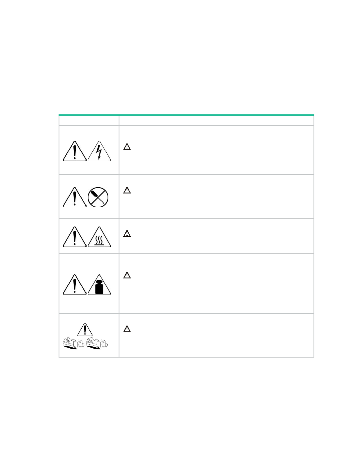
Table 1 Safety signs
Sign Description
Circuit or electricity hazards are present. Only H3C authorized or professional
server engineers are allowed to service, repair, or upgrade the server.
WARNING!
To avoid bodily injury or damage to circuits, do not open any components marked
with the electrical hazard sign unless you have authorization to do so.
Electrical hazards are present. Field servicing or repair is not allowed.
WARNING!
To avoid bodily injury, do not open any components with the field-servicing
forbidden sign in any circumstances.
The surface or component might be hot and present burn hazards.
WARNING!
To avoid being burnt, allow hot surfaces or components to cool before touching
them.
The server or component is heavy and requires more than one people to carry or
move.
WARNING!
To avoid bodily injury or damage to hardware, do not move a heavy component
alone. In addition, observe local occupational health and safety requirements and
guidelines for manual material handling.
The server is powered by multiple power supplies.
WARNING!
To avoid bodily injury from electrical shocks, make sure you disconnect all power
supplies if you are performing offline servicing.
Power source recommendations
Power instability or outage might cause data loss, service disruption, or damage to the server in the
worst case.
To protect the server from unstable power or power outage, use uninterrupted power supplies (UPSs)
to provide power for the server.
1
Page 9
Installation safety recommendations
To avoid bodily injury or damage to the server, read the following information carefully before you
operate the server.
General operating safety
To avoid bodily injury or damage to the server, follow these guidelines when you operate the server:
• Only H3C authorized or professional server engineers are allowed to install, service, repair,
operate, or upgrade the server.
• Make sure all cables are correctly connected before you power on the server.
• Place the server on a clean, stable table or floor for servicing.
• To avoid being burnt, allow the server and its internal modules to cool before touching them.
Electrical safety
WARNING!
If you put the server in standby mode (system LED in amber) with the power on/standby button on
the front panel, the power supplies continue to supply power to some circuits in the server. To
remove all power for servicing safety, you must first press the button until the system enters standby
mode, and then remove all power cords from the server.
To avoid bodily injury or damage to the server, follow these guidelines:
• Always use the power cords that came with the server.
• Do not use the power cords that came with the server for any other devices.
• Power off the server when installing or removing any components that are not hot swappable.
Rack mounting recommendations
To avoid bodily injury or damage to the equipment, follow these guidelines when you rack mount a
server:
• Mount the server in a standard 19-inch rack.
• Make sure the leveling jacks are extended to the floor and the full weight of the rack rests on the
leveling jacks.
• Couple the racks together in multi-rack installations.
• Load the rack from the bottom to the top, with the heaviest hardware unit at the bottom of the
rack.
• Get help to lift and stabilize the server during installation or removal, especially when the server
is not fastened to the rails. As a best practice, a minimum of two people are required to safely
load or unload a rack. A third person might be required to help align the server if the server is
installed higher than check level.
• For rack stability, make sure only one unit is extended at a time. A rack might get unstable if
more than one server unit is extended.
• Make sure the rack is stable when you operate a server in the rack.
• To maintain correct airflow and avoid thermal damage to the server, use blanking panels to fill
empty rack units.
2
Page 10

ESD prevention
Electrostatic charges that build up on people and tools might damage or shorten the lifespan of the
system board and electrostatic-sensitive components.
Preventing electrostatic discharge
To prevent electrostatic damage, follow these guidelines:
• Transport or store the server with the components in antistatic bags.
• Keep the electrostatic-sensitive components in the antistatic bags until they arrive at an
ESD-protected area.
• Place the components on a grounded surface before removing them from their antistatic bags.
• Avoid touching pins, leads, or circuitry.
• Make sure you are reliably grounded when touching an electrostatic-sensitive component or
assembly.
Grounding methods to prevent electrostatic discharge
The following are grounding methods that you can use to prevent electrostatic discharge:
• Wear an ESD wrist strap and make sure it makes good skin contact and is reliably grounded.
• Take adequate personal grounding measures, including wearing antistatic clothing, static
dissipative shoes, and antistatic gloves.
• Use conductive field service tools.
• Use a portable field service kit with a folding static-dissipating work mat.
Cooling performance
Poor cooling performance might result from improper airflow and poor ventilation and might cause
damage to the server.
To ensure good ventilation and proper airflow, follow these guidelines:
• Install blanks if the following module slots are empty:
{ Drive bays.
{ Fan bays.
{ PCIe slots.
{ Power supply slots.
• Do not block the ventilation openings in the server chassis.
• To avoid thermal damage to the server, do not operate the server for long periods in any of the
following conditions:
{ Access panel open or uninstalled.
{ Air baffles uninstalled.
{ PCIe slots, drive bays, fan bays, or power supply slots empty.
• Install rack blanks to cover unused rack spaces.
Battery safety
The server's system board contains a system battery, which is designed with a lifespan of 5 to 10
years.
If the server no longer automatically displays the correct date and time, you might need to replace
the battery. When you replace the battery, follow these safety guidelines:
3
Page 11

• Do not attempt to recharge the battery.
• Do not expose the battery to a temperature higher than 60°C (140°F).
• Do not disassemble, crush, puncture, short external contacts, or dispose of the battery in fire or
water.
• Dispose of the battery at a designated facility. Do not throw the battery away together with other
wastes.
4
Page 12
Preparing for installation
The server is 2U high. Prepare a standard 19-inch rack to install the server.
Plan an installation site that meets the requirements of space and airflow, temperature, humidity,
equipment room height, cleanliness, and grounding.
Installation site requirements
Space and airflow requirements
For convenient maintenance and heat dissipation, make sure the following requirements are met:
• A minimum clearance of 635 mm (25 in) is reserved in front of the rack.
• A minimum clearance of 762 mm (30 in) is reserved behind the rack.
• A minimum clearance of 1219 mm (47.99 in) is reserved between racks.
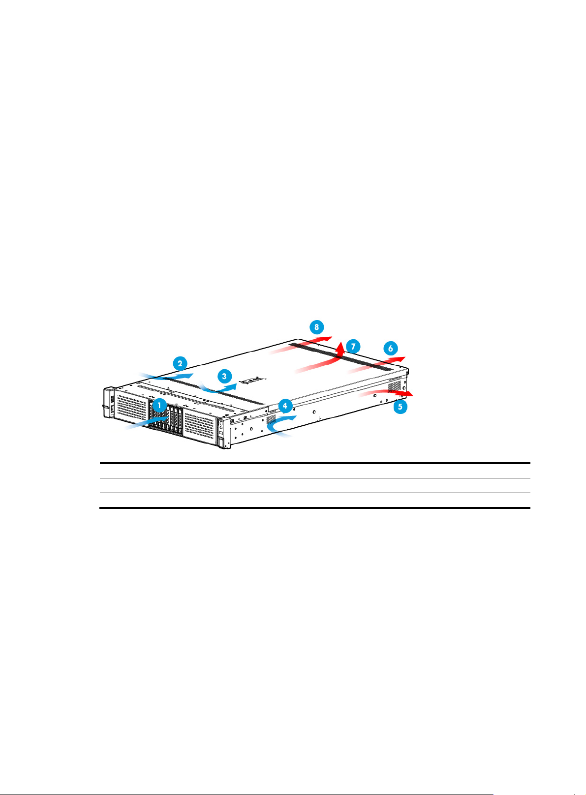
Figure 1 Airflow through the server
(1) to (4) Directions of the airflow into the chassis and power supplies
(5) to (7) Directions of the airflow out of the chassis
(8) Direction of the airflow out of the power supplies
Temperature, humidity, and altitude requirements
To ensure correct operation of the server, make sure the room temperature, humidity, and altitude
meet the requirements as described in "Appendix A Server specifications."
Cleanliness requirements
Mechanically active substances buildup on the chassis might result in electrostatic adsorption, which
causes poor contact of metal components and contact points. In the worst case, electrostatic
adsorption can cause communication failure.
5
Page 13
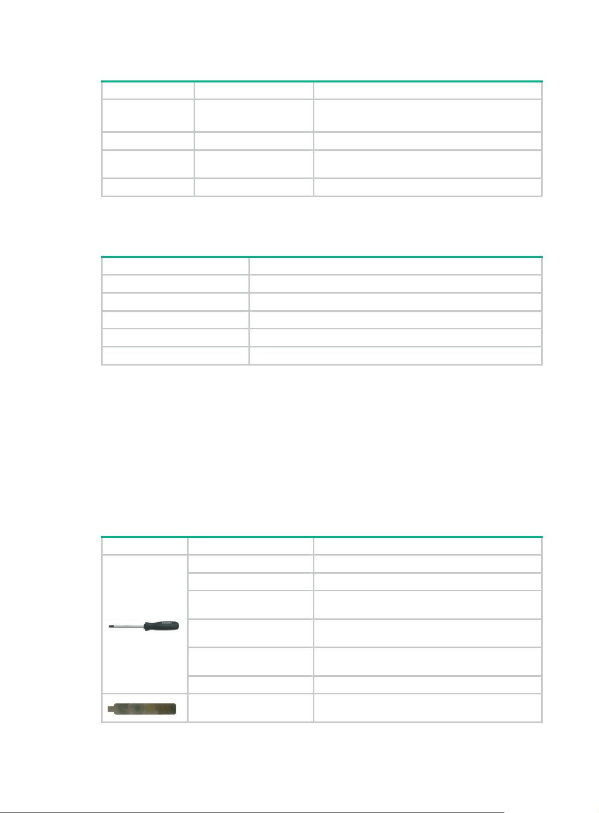
Table 2 Mechanically active substance concentration limit in the equipment room
Substance Particle diameter Concentration limit
Dust particles ≥ 5 µm
Dust (suspension) ≤ 75 µm ≤ 0.2 mg/m3
≤ 3 x 10⁴ particles/m3
(No visible dust on desk in three days)
Dust
(sedimentation)
Sand ≥ 150 µm ≤ 30 mg/m3
75 µm to 150 µm ≤ 1.5 mg/(m
The equipment room must also meet limits on salts, acids, and sulfides to eliminate corrosion and
premature aging of components, as shown in Table 3.
Table 3
Harmful gas limits in an equipment room
Gas Maximum concentration (mg/m
SO2 0.2
H2S 0.006
NO2 0.04
NH
3
Cl
2
Grounding requirements
Correctly connecting the server grounding cable is crucial to lightning protection, anti-interference,
and ESD prevention. The server can be grounded through the grounding wire of the power supply
system and no external grounding cable is required.
0.05
0.01
2
h)
3
)
Installation tools
Table 4 lists the tools that you might use during installation.
Table 4 Installation tools
Picture Name Description
T25 Torx screwdriver For captive screws inside chassis ears.
T30 Torx screwdriver For captive screws on processor heatsinks.
T15 Torx screwdriver
(shipped with the server)
T10 Torx screwdriver
(shipped with the server)
Flat-head screwdriver
Phillips screwdriver For screws on SATA M.2 SSDs.
Cage nut insertion/extraction
tool
For screws on access panels.
For screws on PCIe module blanks or riser card
blanks.
For captive screws inside chassis ears or for replacing
system batteries.
For insertion and extraction of cage nuts in rack posts.
6
Page 14
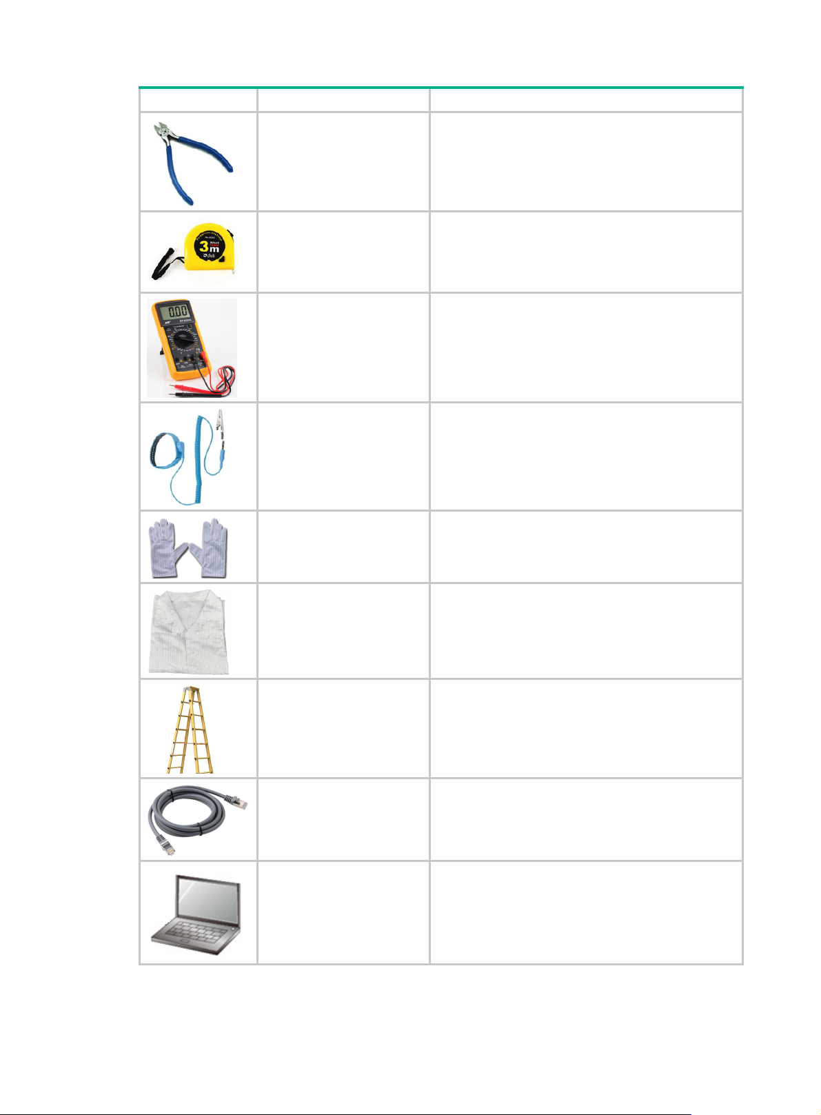
Picture Name Description
Diagonal pliers For clipping insulating sleeves.
Tape measure For distance measurement.
Multimeter For resistance and voltage measurement.
ESD wrist strap For ESD prevention when you operate the server.
Antistatic gloves For ESD prevention when you operate the server.
Antistatic clothing For ESD prevention when you operate the server.
Ladder For high-place operations.
Interface cable (such as an
Ethernet cable or optical
For connecting the server to an external network.
fiber)
Monitor (such as a PC) For displaying the output from the server.
7
Page 15
Installing or removing the server
Installing the server
As a best practice, install hardware options on the server (if needed) before installing the server in
the rack. For more information about how to install hardware options, see "Installing hardware
s."
option
Installing rails
Install the inner rails and the middle-outer rails in the rack mounting rail kit to the server and the rack,
respectively. For information about installing the rails, see the document shipped with the rails.
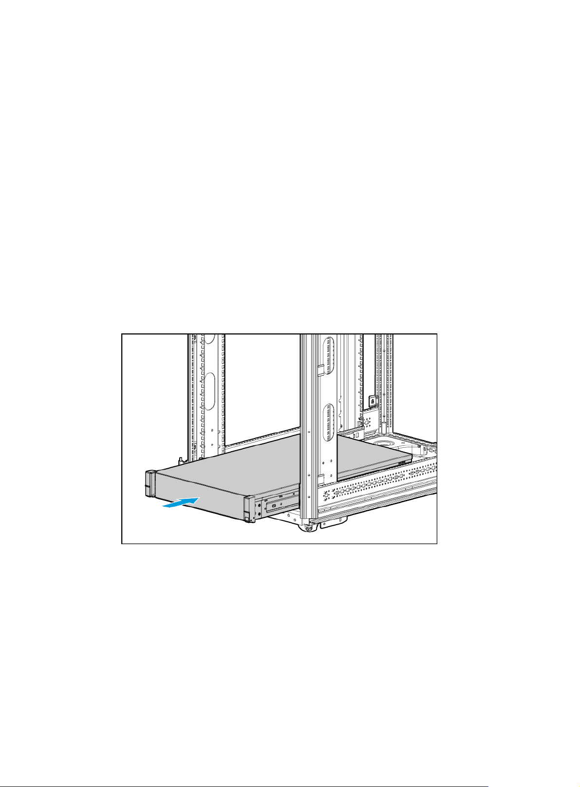
Rack-mounting the server
1. Slide the server into the rack. For more information about how to slide the server into the rack,
see the document shipped with the rails.
Figure 2 Rack-mounting the server
2. Secure the server.
a. Push the server until the chassis ears are flush against the rack front posts, as shown by
callout 1 in Figure 3.
b. Unlo
c. Fasten th
ck the latches of the chassis ears, as shown by callout 2 in Figure 3.
e captive screws inside the chassis ears and lock the latches, as shown by callout
3 in Figure 3.
8
Page 16

Figure 3 Securing the server
(Optional) Installing cable management brackets
Install cable management brackets if the server is shipped with cable management brackets. For
information about how to install cable management brackets, see the installation guide shipped with
the brackets.
Connecting external cables
Cabling guidelines
WARNING!
To avoid electric shock, fire, or damage to the equipment, do not connect communication equipment
to RJ-45 Ethernet ports on the server.
• For heat dissipation, make sure no cables block the inlet or outlet air vents of the server.
• To easily identify ports and connect/disconnect cables, make sure the cables do not cross.
• Label the cables for easy identification.
• Wrap unused cables onto an appropriate position on the rack.
• To avoid damage to cables when extending the server out of the rack, do not route the cables
too tight if you use cable management brackets.
Connecting a mouse, keyboard, and monitor
About this task
Perform this task before you configure BIOS, HDM, or FIST on the server.
The server provides a VGA connector on the rear panel for connecting a monitor. An additional VGA
connector is provided if the left chassis ear has one.
9
Page 17

IMPORTANT!
The two VGA connectors on the server cannot be used at the same time.
The server does not provide ports for standard PS2 mouse and keyboard. To connect a PS2 mouse
or keyboard, you must prepare a USB-to-PS2 adapter.
Procedure
1. Connect one plug of a VGA cable to a VGA connector on the server, and fasten the screws on
the plug.
Figure 4 Connecting a VGA cable
2. Connect the other plug of the VGA cable to the VGA connector on the monitor, and fasten the
screws on the plug.
3. Connect the mouse and keyboard.
{ For a USB mouse and keyboard, directly connect the USB connectors of the mouse and
keyboard to the USB connectors on the server.
{ For a PS2 mouse and keyboard, insert the USB connector of the USB-to-PS2 adapter to a
USB connector on the server. Then, insert the PS2 connectors of the mouse and keyboard
into the PS2 receptacles of the adapter.
10
Page 18

Figure 5 Connecting a PS2 mouse and keyboard by using a USB-to-PS2 adapter
Connecting an Ethernet cable
About this task
Perform this task before you set up a network environment or log in to the HDM management
interface through the HDM network port to manage the server.
Procedure
1. Determine the network port on the server.
{ To connect the server to the external network, use the Ethernet port on the Ethernet
{ To log in to the HDM management interface, use the HDM network port on the server. For
2. Verify the connectivity of the cable by using a link tester.
If you are replacing the Ethernet cable, make sure the new cable is of the same type with the old
cable or compatible with the old cable.
3. Label the Ethernet cable by filling in the names and numbers of the server and the peer device
on the label.
As a best practice, use labels of the same kind for all cables.
If you are replacing the Ethernet cable, label the new cable with the same number as the
number of the old cable.
4. Connect one end of the Ethernet cable to the network port on the server and the other end to
the peer device.
adapter.
the position of the HDM network port, see "Rear panel view."
11
Page 19

Figure 6 Connecting an Ethernet cable
5. Verify network connectivity.
After powering on the server, use the ping command to test the network connectivity. If the
connection between the server and the peer device fails, make sure the Ethernet cable is
correctly connected.
6. Secure the Ethernet cable. For information about how to secure cables, see "Securing cables."
Connecting a USB device
About this task
Perform this task before you transmit data through a USB device.
The server provides a maximum of six USB connectors.
• One USB 2.0 connector and one USB 3.0 connector on the front panel if an installed chassis
ear contains a VGA connector, a USB 2.0 connector, and a USB 3.0 connector.
• Two USB 3.0 connectors on the rear panel.
• Two internal USB 2.0 connector for connecting USB devices that are not designed to be
installed and removed very often.
Guidelines
Before connecting a USB device, make sure the USB device can operate correctly and then copy
data to the USB device.
USB devices are hot swappable.
As a best practice for compatibility, purchase H3C certified USB devices.
Procedure
1. (Optional.) Remove the access panel if you need to connect the USB device to an internal USB
connector. For information about how to remove the access panel, see "Removing the access
panel."
2. Connect the USB device to the USB connector, as shown in Figure 7.
12
Page 20

Figure 7 Connecting a USB device to an internal USB connector
3. (Optional.) Install the access panel. For information about how to install the access panel, see
"Installing the access panel."
4. Verify that th
e server can identify the USB device.
If the server fails to identify the USB device, download and install the driver for the USB device.
If the server still fails to identify the USB device after the driver is installed, replace the USB
device.
Connecting the power cord
Guidelines
WARNING!
To avoid damage to the equipment or even bodily injury, use the power cord that ships with the
server.
Before connecting the power cord, make sure the server and components are installed correctly.
Procedure
1. Insert the power cord plug into the power receptacle of a power supply at the rear panel, as
shown in Figure 8.
13
Page 21

Figure 8 Connecting the power cord
2. Connect the other end of the power cord to the power source, for example, the power strip on
the rack.
3. Secure the power cord to avoid unexpected disconnection of the power cord.
a. (Optional.) If the cable clamp is positioned too near the power cord and blocks the power
cord plug connection, press down the tab on the cable mount and slide the clamp backward.
Figure 9 Sliding the cable clamp backward
b. Open the cable clamp, place the power cord through the opening in the cable clamp, and
then close the cable clamp, as shown by callouts 1, 2, 3, and 4 in Figure 10.
14
Page 22

Figure 10 Securing the power cord
c. Slide the cable clamp forward until it is flush against the edge of the power cord plug, as
shown in Figure 11.
Figure 11
Securing cables
Sliding the cable clamp forward
Securing cables to cable management brackets
For information about how to secure cables to cable management brackets, see the installation
guide shipped with the brackets.
Securing cables to slide rails by using cable straps
You can secure cables to either left slide rails or right slide rails. As a best practice for cable
management, secure cables to left slide rails.
15
Page 23

When multiple cable straps are used in the same rack, stagger the strap location, so that the straps
are adjacent to each other when viewed from top to bottom. This positioning will enable the slide rails
to slide easily in and out of the rack.
To secure cables to slide rails by using cable straps:
1. Hold the cables against a slide rail.
2. Wrap the strap around the slide rail and loop the end of the cable strap through the buckle.
3. Dress the cable strap to ensure that the extra length and buckle part of the strap are facing
outside of the slide rail.
Figure 12 Securing cables to a slide rail
Removing the server from a rack
1. Power down the server. For more information, see "Powering off the server."
2. Disconnect all peripheral cables from the server.
3. Extend the server from the rack, as shown in Figure 13.
a. Open the lat
b. Loosen the captive screws.
c. Slide the server out of the rack.
ches of the chassis ears.
16
Page 24

Figure 13 Extending the server from the rack
4. Place the server on a clean, stable surface.
17
Page 25

Powering on and powering off the server
Important information
If the server is connected to external storage devices, make sure the server is the first device to
power off and then the last device to power on. This restriction prevents the server from mistakenly
identifying the external storage devices as faulty devices.
Powering on the server
Prerequisites
Before you power on the server, you must complete the following tasks:
• Install the server and internal components correctly.
• Connect the server to a power source.
Procedure
Powering on the server by pressing the power on/standby button
Press the power on/standby button to power on the server.
The server exits standby mode and supplies power to the system. The system power LED changes
from steady amber to flashing green and then to steady green. For information about the position of
the system power LED, see "LEDs and buttons."
Powering on the server from the HDM Web interface
1. Log in to the HDM.
2. In the navigation pane, select Power Manager > Power Control.
The power control configuration page opens.
3. Select Power on and then click Execute.
Powering on the server from the remote console interface
1. Log in to HDM.
2. Log in to a remote console and then power on the server.
For information about how to log in to a remote console, see HDM online help.
Configuring automatic power-on
1. Log in to HDM.
2. In the navigation pane, select Power Manager > Meter Power.
The meter power configuration page opens.
3. Click the Automatic power-on tab and then select Always power on.
4. Click Save.
18
Page 26

Powering off the server
Guidelines
Before powering off the server, you must complete the following tasks:
• Install the server and internal components correctly.
• Backup all critical data.
• Make sure all services have stopped or have been migrated to other servers.
Procedure
Powering off the server from its operating system
1. Connect a monitor, mouse, and keyboard to the server.
2. Shut down the operating system of the server.
3. Disconnect all power cords from the server.
Powering off the server by pressing the power on/standby button
1. Press and hold the power on/standby button until the system power LED turns into steady
amber.
This method forces the server to enter standby mode without properly exiting applications and
the operating system. If an application stops responding, you can use this method to force a
shutdown.
2. Disconnect all power cords from the server.
Powering off the server from the HDM Web interface
1. Log in to HDM.
2. In the navigation pane, select Power Manager > Power Control.
The power control configuration page opens.
3. Select Force power-off or Graceful power-off and then click Execute to put the server in
standby mode.
4. Disconnect all power cords from the server.
Powering off the server from the remote console interface
1. Log in to HDM.
2. Log in to a remote console and then power off the server.
For information about how to log in to a remote console, see HDM online help.
3. Disconnect all power cords from the server.
19
Page 27

Configuring the server
The following information describes the procedures to configure the server after the server
installation is complete.
Powering on the server
1. Power on the server. For information about the procedures, see "Powering on the server."
2. Verify that the health LED on the front panel is steady green, which indicates that the system is
operating correctly. For more information about the health LED status, see "LEDs and buttons."
Updating firmware
IMPORTANT:
Verify the hardware and software compatibility before firmware upgrade. For information about the
hardware and software compatibility, see the software release notes.
You can update the following firmware from FIST or HDM:
• HDM.
• BIOS.
• CPLD.
For information about the update procedures, see the firmware update guide for the server.
20
Page 28

Accessing the UIS Manager
Preparing for the access
Connecting the network port
Connect the server to the network through port 1 on the mLOM Ethernet adapter. This port is the
management interface for UIS Manager. For more information about the IP address of the
management interface, see " Obtaining the UIS Manager IP address."
Setting up the configuration terminal
The UIS Manager does not require installation of any client software. You can use a Web browser to
access the UIS Manager.
Make sure the browser and resolution setting of the configuration terminal meet the requirements
in Table 5.
Table 5
Browser and resolution requirements
Browsers Resolution
Google Chrome 45.0 (or higher)
Mozilla Firefox 49.0 (or higher)
Recommended: 1440*900 (or higher)
Obtaining the UIS Manager IP address
1. Connect the HDM dedicated network port to the PC, and then power on the server.
Figure 14 Connecting the HDM dedicated network port to the PC
2. Access the HDM login page at https://HDM_dedicated_network_port_IP.
HDM_dedicated_network_port_IP represents the IP address (network mask excluded) of the
HDM dedicated network port. The IP address is 192.168.1.2/24 by default.
21
Page 29

3. On the sign-in page, enter the username and password, and then click Sign in.
The default username and password are admin and Password@_, respectively.
4. In the navigation pane, select Remote Control > Remote Console.
5. Enter the username and password for the remote console to open the remote console. Both the
default username and password are root.
If a DHCP server exists in the management network, the Configuration screen displays the
UIS Manager IP address obtained from the DHCP server. If no DHCP server exists in the
management network, the network parameter fields on the Configuration screen are empty.
Figure 15 Remote console
6. Specify a static IP address for UIS Manager.
Logging in to UIS Manager
1. Access the UIS Manager login page at http://manage_node_management_IP:8080 or
https://manage_node_management_IP:8443.
manage_node_management_IP represents the management interface IP address of the
management node. For more information, see "Obtaining the UIS Manager IP address."
22
Page 30

Figure 16 UIS Manager login page
2. Enter your username and password and then click Login. Both the default username and
password are admin.
Launching the UIS Setup Wizard
You can deploy UIS Manager through compute virtualization or hyper-converged infrastructure
(HCI).
• Compute virtualization deployment—Deploys only Cloud Virtualization Kernel (CVK) and
provides storage services through an IP SAN or FC SAN. A minimum of one UIS host is
required.
• HCI deployment—Deploys both CVK and distributed storage. A minimum of three UIS hosts
are required.
NOTE:
Unless otherwise stated, a host in this guide refers to a UIS server.
Deploying UIS Manager in the compute virtualization scenario
Setting up UIS
1. Access UIS Manager.
2. Select the system language.
23
Page 31

Figure 17 Selecting the system language
3. On the UIS Setup Wizard page, click Virtualization.
Figure 18 Selecting a scenario
4. Configure network parameters as needed, and then click Next.
24
Page 32

Figure 19 Configuring network parameters
5. In the dialog box that opens, click OK.
Figure 20 Configuration tip
NOTE:
If the start IP address is different from the management interface IP used for login, the system
refreshes the page and opens the Hosts page by using the start IP address. At next login, you
must use the start IP address as the management IP address.
6. Select hosts for the storage cluster.
25
Page 33

Figure 21 Selecting hosts for the storage cluster
7. Click the icon for a host.
8. Configure the following settings:
{
NIC Template—Select whether to apply physical interface settings on the host to other
hosts. For this feature to take effect, make sure the other hosts have active physical
interfaces of the same names as those on this host and the interface speeds are as required.
If a host cannot meet the requirements, you must configure physical interface settings for
the host manually.
{
IP Address—Specify a management IP address for the node. The management IP address
of the management node is the specified start IP address on the Network page and cannot
be modified. If you do not specify a management IP address for a storage or monitor node,
the system assigns an available IP next to the start IP with an increment of 1 to the host. You
do not need to specify a service network IP for a host.
Figure 22 Customizing configuration for a host
9. Click the icon for the management network (required) and service network to specify a
physical interface for them, and then click OK.
10. Configure the following parameters and then click OK:
{
LAGG Mode—Select the aggregation mode of physical NICs in the management network.
Options include Static and Dynamic. The physical switch must be enabled with LACP if the
26
Page 34

dynamic LAGG mode is used. This parameter is displayed only when multiple physical
interfaces are configured for the management network.
{ LB Mode—Select the load balancing mode of physical NICs in the management network.
Options include Advanced, Basic, and Active/Standby. This parameter is displayed only
when multiple physical interfaces are configured for the management network.
− Advanced—Load balances physical NICs based on the Ethernet type, IP protocol,
source IP address, destination IP address, source port number, and destination port
number of packets.
− Basic—Load balances physical NICs based on the source MAC address and VLAN tag
of packets.
− Active/Standby—Load balances the active and standby physical NICs. When the
active physical NIC fails, the system switches to the standby physical NIC for traffic
forwarding. This option is displayed only when the static LAGG mode is used.
Figure 23 Selecting physical interfaces
11. Click OK.
12. Click Finish.
13. Set the root password for all hosts. The password must contain a minimum of eight characters.
It cannot contain only letters, digits, or special characters.
Figure 24 Setting the root password
14. Click OK.
27
Page 35

The system starts to configure the host and will open the UIS Manager homepage after host
configuration.
Figure 25 Configuring the host
Adding a virtual switch
A virtual switch provides software-based switching between VMs, hosts, and the external network.
Perform this task only when IP SAN storage is used.
To add a virtual switch:
1. On the top navigation bar, click Networks, and then select vSwitches from the navigation
pane.
Figure 26 Accessing the vSwitches list
2. Click Add.
3. Enter the vSwitch name, select Storage as the network type, select VEB as the forwarding
mode, and enter the VLAN ID.
28
Page 36

Figure 27 Configuring basic vSwitch information
4. Click Next.
5. Select the hosts on which you want to create a virtual switch.
Figure 28 Configuring host information
6. Click the icon for each host to configure physical interface information. On the window that
opens, select one physical interface or two physical interfaces to form an aggregate interface,
enter IP address and subnet mask, and then click Finish.
29
Page 37

Figure 29 Configuring physical interfaces
7. Click Finish when the page as shown in Figure 28 appears.
Configuring network-shared storage
Make sure the storage device is reachable from the host.
To configure network-shared IP SAN storage, start from step 1. To configure network-shared FC
SAN storage, start from step 4.
To configure network shared storage:
1. On the top navigation bar, click Hosts, and then select a host from the navigation pane.
Figure 30 Viewing detailed host information
2. Click the Hardware Configuration tab and then select Storage to view the IQN for the host. To
change the IQN, click the Edit icon .
30
Page 38

Figure 31 Obtaining the host IQN
3. Configure network-shared storage settings on the iSCSI storage device, including host, LUN,
and LUN-host mapping settings.
4. In UIS Manager, click Storage on the top navigation bar, and select Shared Storage from the
navigation pane.
Figure 32 Configuring shared storage
5. Click Add.
6. Configure the following parameters:
{ Type—To access an IP SAN storage device, select iSCSI Shared Directory. To access an
FC SAN storage device, select FC Shared Directory.
{ Target Path—Select a point to mount the shared file system in the client.
31
Page 39

Figure 33 Configuring basic shared storage information
7. Click Next.
8. Configure the following parameters:
{ IP Address—Specify the IP address of the IP SAN storage server. This field is required for
an iSCSI shared directory. If multiple paths are available, use semicolons (;) to separate the
IP addresses.
{ LUN—Specify a LUN for the shared file system. This field is required for an iSCSI shared
directory.
{ NAA—Specify the network addressing authority identifier for the LUN, which is a unique
identifier of the LUN on the storage server. For an iSCSI shared directory, this field is
automatically determined by the selected LUN. For an FC shared directory, you must select
a LUN for this field.
{ Service Storage—Enable this option to allow the shared file system to be used for storing
files of the VMs automatically deployed by the system. As a best practice, enable this
option.
Figure 34 Configuring LUN information
32
Page 40

9. Click Next.
10. Select hosts that can act as clients to access the shared storage, and then click Finish.
11. In the confirmation dialog box that opens, click OK.
Figure 35 Confirming the shared storage adding operation
12. In the dialog box that opens, click OK to format the shared file system.
Figure 36 Formatting the shared file system
After shared storage configuration, you can create virtual machines in UIS Manager.
Deploying UIS Manager in the HCI scenario
Setting up UIS
1. Access UIS Manager.
2. On the UIS Setup Wizard page, click HCI.
33
Page 41

Figure 37 Selecting a scenario
3. Configure network parameters and then click Next.
Figure 38 Configuring network parameters
4. In the dialog box that opens, click OK.
Figure 39 Configuration tip
34
Page 42

NOTE:
If the start IP address is different from the management interface IP used for login, the system
refreshes the page and opens the Hosts page by using the start IP address. At next login, you
must use the start IP address as the management IP address.
5. Select hosts for the storage cluster.
Figure 40 Selecting hosts for the storage cluster
6. Click the icon for a host.
7. Configure the following settings:
{
NIC Template—Select whether to apply physical interface settings of the host to other
hosts. For this feature to take effect, make sure the other hosts have active physical
interfaces of the same names as those on this host and the interface speeds are as required.
If a host cannot meet the requirements, you must configure physical interface settings for
the host manually.
{
IP Address—Specify an IP address for the management, storage back-end, and storage
front-end networks. The start IP addresses specified in the UIS Setup Wizard are used for
the management node. For a non-management node, if you do not specify an IP address
manually, the system assigns an available IP next to the start IP with an increment of 1 to
the host. You do not need to specify an IP address for the service network.
Figure 41 Customizing configuration for a host
35
Page 43

8. Click the icon for a management network, service network (optional), storage back-end
network, and storage front-end network to specify a physical interface for them, and then click
OK.
9. Configure the following parameters and then click OK:
{ LAGG Mode—Select the aggregation mode of physical NICs in the management network.
Options include Static and Dynamic. The physical switch must be enabled with LACP if the
dynamic LAGG mode is used. This parameter is displayed only when multiple physical
interfaces are configured for the management network.
{ LB Mode—Select the load balancing mode of physical NICs in the management network.
Options include Advanced, Basic, and Active/Standby. This parameter is displayed only
when multiple physical interfaces are configured for the management network.
− Advanced—Load balances physical NICs based on the Ethernet type, IP protocol,
source IP address, destination IP address, source port number, and destination port
number of packets.
− Basic—Load balances physical NICs based on the source MAC address and VLAN tag
of packets.
− Active/Standby—Load balances the active and standby physical NICs. When the
active physical NIC fails, the system switches to the standby physical NIC for traffic
forwarding. This option is displayed only when the static LAGG mode is used.
Figure 42 Selecting physical interfaces
10. Click OK.
11. Click Set Password on the Network page as shown in Figure 40.
12. Set the root password for al
l hosts and then click OK. The password must contain a minimum of
eight characters. It cannot contain only letters, digits, or special characters.
36
Page 44

Figure 43 Setting the root password
13. Click Next on the Network page as shown in Figure 40 and then verify the host settings.
Figure 44 Verifying host settings
14. Click OK.
The system starts to configure the host.
Figure 45 Configuring the host
15. On the Storage page, configure the following parameters:
37
Page 45

{ Deployment Mode—Select the storage cluster deployment mode. Options include SSD
Caches+HDDs, All SSDs, All HDDs, and HDDs+SSDs.
{ Replicas—Set the number of replicas. After UIS setup, the system creates a replication
redundancy policy with the specified number of replicas and a thin-provisioned block device
that uses the redundancy policy. The maximum capacity of the block device is 80% of the
total available capacity of the storage cluster or 16 TB (if the 80% total available capacity
exceeds 16 TB).
{ Write Cache/HDD—Specify the size of the write cache partition for each HDD. The total
size of write cache partitions for all HDDs must be smaller than the SSD size specified for
the write cache. This field is required when the deployment mode is SSD Caches+HDDs.
{ Read Cache/HDD—Specify the size of the read cache partition for each HDD. The total
size of read cache partitions for all HDDs must be smaller than the SSD size specified for
the read cache. This field is required when the deployment mode is SSD Caches+HDDs.
To edit the host role, write cache, read cache, or data disks, click the icon for a host.
Figure 46 Configuring storage parameters
16. Click Finish.
17. In the dialog box that opens, click OK.
Figure 47 Operation confirming
The system starts to deploy distributed storage and will open the UIS Manager homepage after
deployment. Then, you can create virtual machines in UIS Manager.
38
Page 46

Figure 48 Deploying distributed storage
39
Page 47

Registering licenses
UIS Manager provides the following licenses:
• UIS licenses—Charged on the number of physical CPUs.
• Distributed storage licenses—Charged on disk capacity.
Obtaining licenses
UIS Manager provides a 180-day free trial edition. To continue to use UIS Manager after the trial
period expires, purchase an official edition.
The trial and official editions provide the same functions.
Obtaining host information files
1. Access the UIS Manager login page at http://manage_node_management_IP:8080 or
https://manage_node_management_IP:8443.
manage_node_management_IP represents the management interface IP address of the
management node.
2. Click Product Registration.
Figure 49 UIS Manager login page
3. Enter the root password (admin by default) and select Request or Update a License from the
License Actions field. Then, click Next.
40
Page 48

Figure 50 Specifying a license action
4. Enter the end user information and applicant information, and then click Next.
Figure 51 Entering registration information
5. Click Download.
The host information file package is downloaded to the local disk. The name of the host
information file package is UIS_hosts_info.tar.gz by default. The package contains two files:
CAS_host.info and Storage_ip_host_info. ip represents the IP address of the management
node.
IMPORTANT:
Do not change the names of files CAS_host.info and Storage_ip_host_info.
41
Page 49

Figure 52 Downloading the host information file
Obtaining license keys
Obtain license keys from the franchiser.
Obtaining a license file
1. Access http://www.h3c.com.hk/Technical_Support___Documents/Product_Licensing/.
2. Click Register the First Time.
3. Obtain license files and save the files to a local directory.
{ To obtain a UIS Manager license file, select Cloud_H3C Automation System as the
product category, upload file CAS_host.info, and click Get activation key or file.
{ To obtain a distributed storage license file, select Distributed Storage_H3C ONEStor as
the product category, upload file Storage_ip_host_info, and click Get activation key or file.
Registering UIS licenses and distributed storage licenses
Registering a UIS license
1. Access the UIS Manager login page at http://manage_node_management_IP:8080 or
https://manage_node_management_IP:8443.
2. Click Product Registration.
42
 Loading...