

H3C SR8800-X-S Installation, Quick Start

Contents
Installation Quick Start ················································································································································· 1
Preparing for installation ·················································································································································· 1
ESD prevention ························································································································································· 1
Examining the installation site ································································································································· 1
Installation tools and accessories ··························································································································· 2
Installing the router ···························································································································································· 2
Confirming installation preparations ······················································································································ 3
Installing cage nuts ··················································································································································· 3
Installing the cable management bracket and mounting brackets ······································································ 5
Mounting the router in the rack ······························································································································ 6
Grounding the router ··············································································································································· 7
Installing a card ························································································································································ 9
Installing a subcard ··············································································································································· 11
Installing a power module ············································································································································· 12
Verifying the installation ······································································································································· 19
Logging in to the router ················································································································································· 20
Connecting the console cable ······························································································································ 20
Powering on the router ········································································································································· 20
Obtaining documentation ············································································································································· 21
i
Installation Quick Start
This Installation Quick Start provides basic instructions for installing an SR8800-X-S router. For more
detailed installation procedures, see H3C SR8800-X-S Routers Installation Guide.
The figures in this document are for illustration only.
Preparing for installation
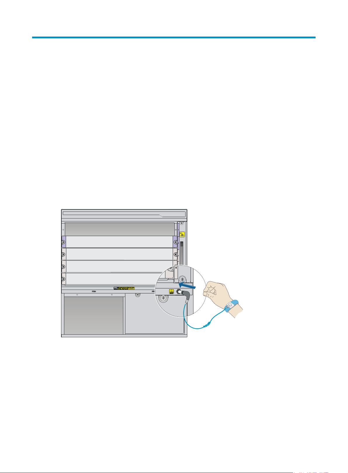
ESD prevention
To prevent the electronic components from being damaged by the electrostatic discharge (ESD), always
do the following before you touch the router, cards, or ICs:
1. Wear an ESD wrist strap.
2. Make sure the wrist strap is correctly grounded.
Figure 1 Attaching an ESD wrist strap (on an SR8803-X-S)
Examining the installation site
The SR8800-X-S routers can only be used indoors. To make sure the router operates correctly and to
prolong its service lifetime, the installation site must meet the load-bearing, temperature, humidity,
cleanness, EMI, grounding, power, and space requirements. For more information, see H3C SR8800-X-S
Routers Installation Guide.
1
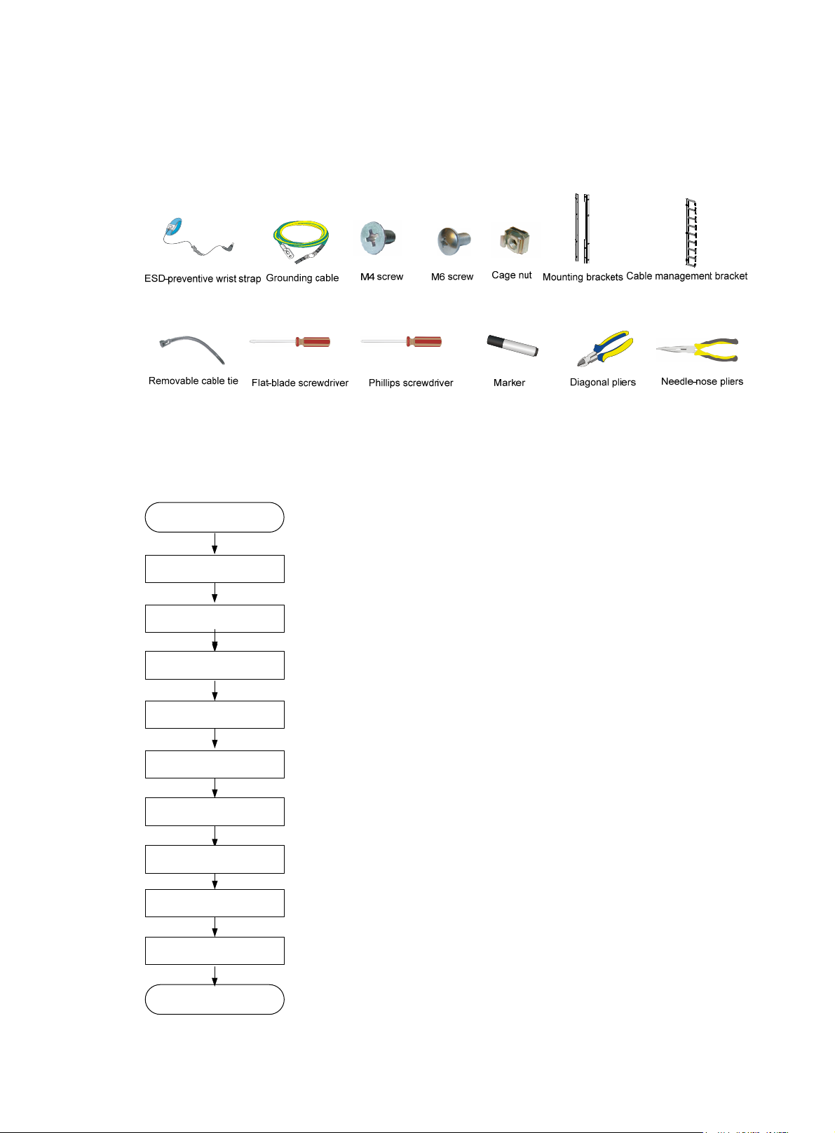
Installation tools and accessories
This section only lists the most commonly used installation accessories and tools.
Figure 2 Installation tools and accessories
Installing the router
Figure 3 Installation flow
Start
Confirm installation
preparations
Install cage nuts
Install mounting brackets and
cable management brackets
Mount the router to the rack
Ground the router
Install a card
Install a subcard (Optional)
Install a power module
Verify the installation
End
2

Confirming installation preparations
H3C recommends that you order the H3C Rack Mounting Kit (LSTM2KSGD0) 500 mm (19.69 in) to 800
mm (31.50 in). For the installation procedures, see the installation guide.
Make sure the bottom edge of the slide rail aligns with the middle of the narrower metal area between
holes, as shown in Figure 4.
Figure 4 Installing the
(1) Middle of the narrower metal area between holes
slide rails
Installing cage nuts
IMPORTANT:
Make sure the total height of the devices to be installed is less than the rack height.
Before mounting the chassis to the rack, install cage nuts to the square holes on the front rack posts.
To install cage nuts to the rack:
1. Determine the positions of the cage nuts according to the holes on the mounting brackets and
positions of the slide rails, as shown in Figure 5.
2. Install c
age nuts to the square holes on each rack post, as shown in Figure 6.
3
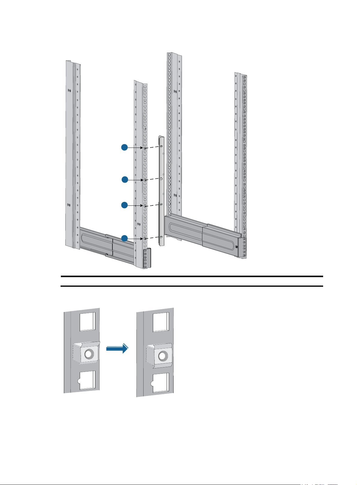
Figure 5 Determining installation positions for cage nuts (SR8803-X-S)
1
1
1
1
(1) Cage nuts
Figure 6 Installing the cage nut
4
Installing the cable management bracket and mounting brackets
Before installing the router to the rack, install the cable management bracket and mounting brackets
shipped with the router. The cable management bracket is used for cable deployment, and mounting
brackets are used for attaching the chassis to the rack. Each router is shipped with two mounting brackets
and one cable management bracket.
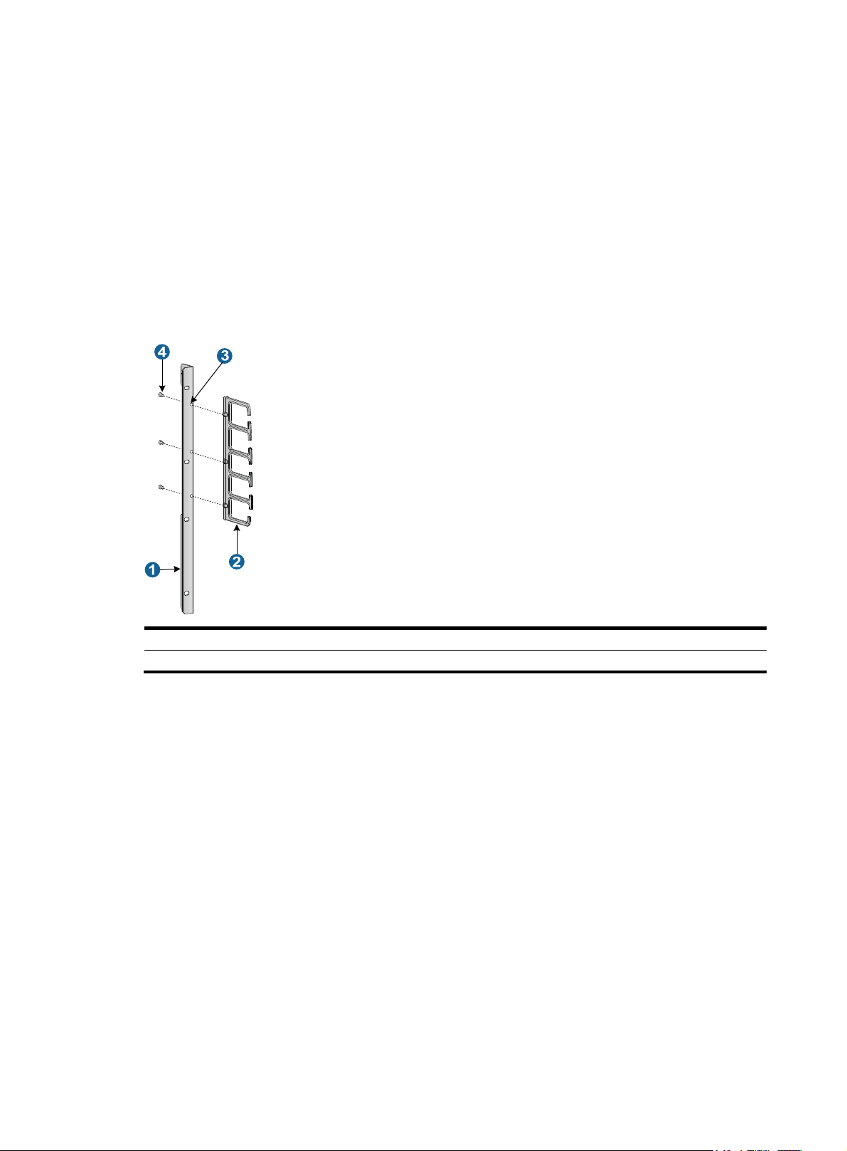
Installing the cable management bracket
Secure the cable management bracket to the left mounting bracket, as shown in Figure 7.
Figure 7 Installing the cable management bracket (SR8803-X-S)
(1) Left mounting bracket (2) Cable management bracket
(3) Installation hole
Attaching mounting brackets to the chassis
Before mount the router in the rack, secure the mounting brackets to the chassis, as shown in Figure 8.
1. Secure the mounting bracket with the cable management bracket to the left front of the router.
2. Secure the mounting bracket without the cable management bracket to the right front of the router
(the fan tray side).
(4) Screw
5
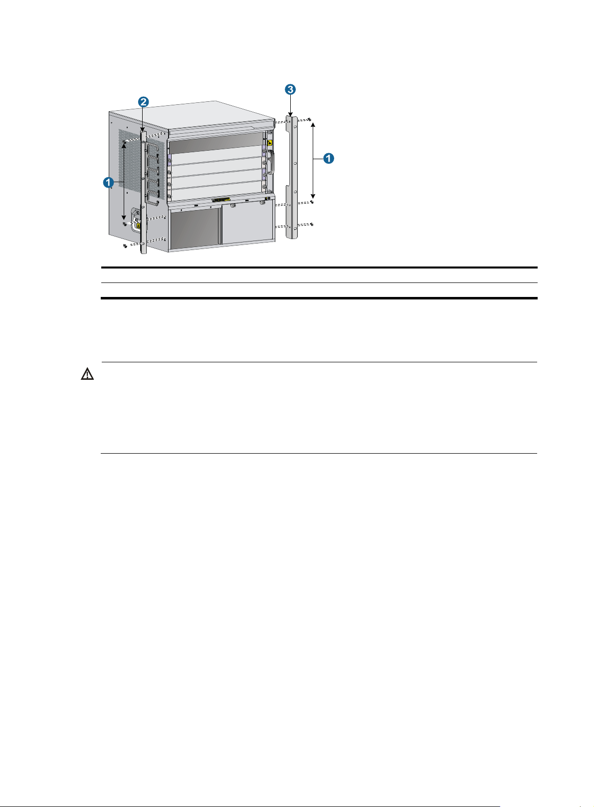
Figure 8 Installing the mounting brackets (SR8803-X-S)
g
W
g
(1) Screw (2) Left mounting bracket
(3) Right mountin
bracket
Mounting the router in the rack
ARNING!
• Do not hold the fan tray handle, the power module handle, the back cover of the chassis, or the air vents
of the chassis to carry the router. Any attempt to carry the router with these parts might cause equipment
damage or even bodily injury.
• After placing the router on the slide rails, do not leave
o of your hands immediately because this might
tip and damage the router, and even cause bodily injury.
To mount the router to the rack:
1. Align the rear of the chassis to the front of the rack.
2. To lift the router, use at least two people or a mechanical lift. Lift the router until the bottom of the
router is a little higher than the slide rails on the rack.
3. Place the router on the slide rails. Slide the router along the slide rails until the mounting brackets
on the router touch the front rack posts, as shown by callout 1 in Figure 9.
4. Secure the
chassis to the rack with screws shipped with the router.
6
 Loading...