

Page 1

H3C SR6608/6604 Routers
Installation Manual
Hangzhou H3C Technologies Co., Ltd.
http://www.h3c.com
Manual Version: T2-08040D-20080516-C-1.02
Page 2

Copyright © 2007-2008, Hangzhou H3C Te chnologie s Co., Ltd . and it s licen sors
All Rights Reserved
No part of this manual may be reproduced or transmitted in any form or by any means
without prior written consent of Hangzhou H3C Technologies Co., Ltd.
Trademarks
H3C, , Aolynk, , H3Care,
Neocean, NeoVTL, SecPro, SecPoint, SecEngine, SecPath, Comware, Secware,
Storware, NQA, VVG, V
HUASAN are trademarks of Hangzhou H3C Technologies Co., Ltd.
All other trademarks that may be mentioned in this manual are the property of their
respective owners.
Notice
The information in this document is subject to change without notice. Every effort has
been made in the preparation of this document to ensure accuracy of the content s, but
all statements, information, and recommendations in this document do not constitute
the warranty of any kind, express or implied.
To obtain the latest information, please access:
http://www.h3c.com
Technical Support
customer_service@h3c.com
http://www.h3c.com
, TOP G, , IRF, NetPilot,
2
G, VnG, PSPT, XGbus, N-Bus, TiGem, InnoVision and
Page 3
About This Manual
Related Documentation
In addition to this manual, each H3C SR66 Series Routers documentation set includes
the following:
Manual Description
H3C SR66 Series Routers User Man ual
It is a guide for the user to perform the
operations correctly. It is organized into
the parts of getting started, system
management, interface, link layer
protocol, network protocol, routing
protocol, security, VPN, and QoS.
It also gives the user a detailed
description of the operating commands.
It is organized into the parts of getting
started, system management, interface,
link layer protocol, network protocol,
routing protocol, security, VPN, QoS, as
well as a command index.
Organization
H3C SR6608/6604 Routers Installation Manual is organized as follows:
Low-End and Mid-Range Series Routers
Cable Manual
Chapter Contents
1 Router Overview
2 Interface Modules
3 Arranging Slots and Numbering
Interfaces
4 Preparing for Installation
This manual introduces all cable pinouts
available with low-end and mid-range
series routers.
Briefly introduces the product
specifications, as well as the features
and applications of the H3C
SR6608/6604 routers.
Describes the interface cards and
interface modules supported by the H3C
SR6608/6604 routers.
Introduces the slots and numbering
rules of the H3C SR6608/6604 routers.
Describes the requirements on
installation site, the safety
recommendations before and during
installation, and the required tools.
Page 4
Chapter Contents
5 Installing the Router
6 Starting and Configuring the Router
7 Maintaining Software
8 Maintaining Hardware
9 Troubleshooting
Introduces how to install the
SR6608/6604 routers, as well as how to
connect the power cable, console cable,
AUX port cable, Ethernet cable,
interface card and interface module
cable.
Helps you get familiar with the basic
knowledge of how to boot and configure
the H3C SR6608/6604 routers, including
device startup, power-on, and
initialization of system files, and so on.
Introduces how to maintain the software
of the H3C SR6608/6604 routers,
including upgrading the software and
updating the configuration files.
Introduces how to maintain the
hardware of the H3C SR6608/6604
routers.
Describes some problems that may
occur during installation and startup of
the router and how to solve them.
Conventions
The manual uses the following conventions:
I. Command conventions
Convention Description
Boldface
italic
[ ]
{ x | y | ... }
[ x | y | ... ]
{ x | y | ... } *
The keywords of a command line are in Boldface.
Command arguments are in italic.
Items (keywords or arguments) in square brackets [ ] are
optional.
Alternative items are grouped in braces and separated by
vertical bars. One is selected.
Optional alternative items are grouped in square brackets
and separated by vertical bars. One or none is selected.
Alternative items are grouped in braces and separated by
vertical bars. A minimum of one or a maximum of all can be
selected.
[ x | y | ... ] *
Optional alternative items are grouped in square brackets
and separated by vertical bars. Many or none can be
selected.
Page 5
Convention Description
&<1-n>
# A line starting with the # sign is comments.
The argument(s) before the ampersand (&) sign can be
entered 1 to n times.
II. GUI conventions
Convention Description
< >
[ ]
/
Button names are inside angle brackets. For example, click
<OK>.
Window names, menu items, data table and field names
are inside square brackets. For example, pop up the [New
User] window.
Multi-level menus are separated by forward slashes. For
example, [File/Create/Folder].
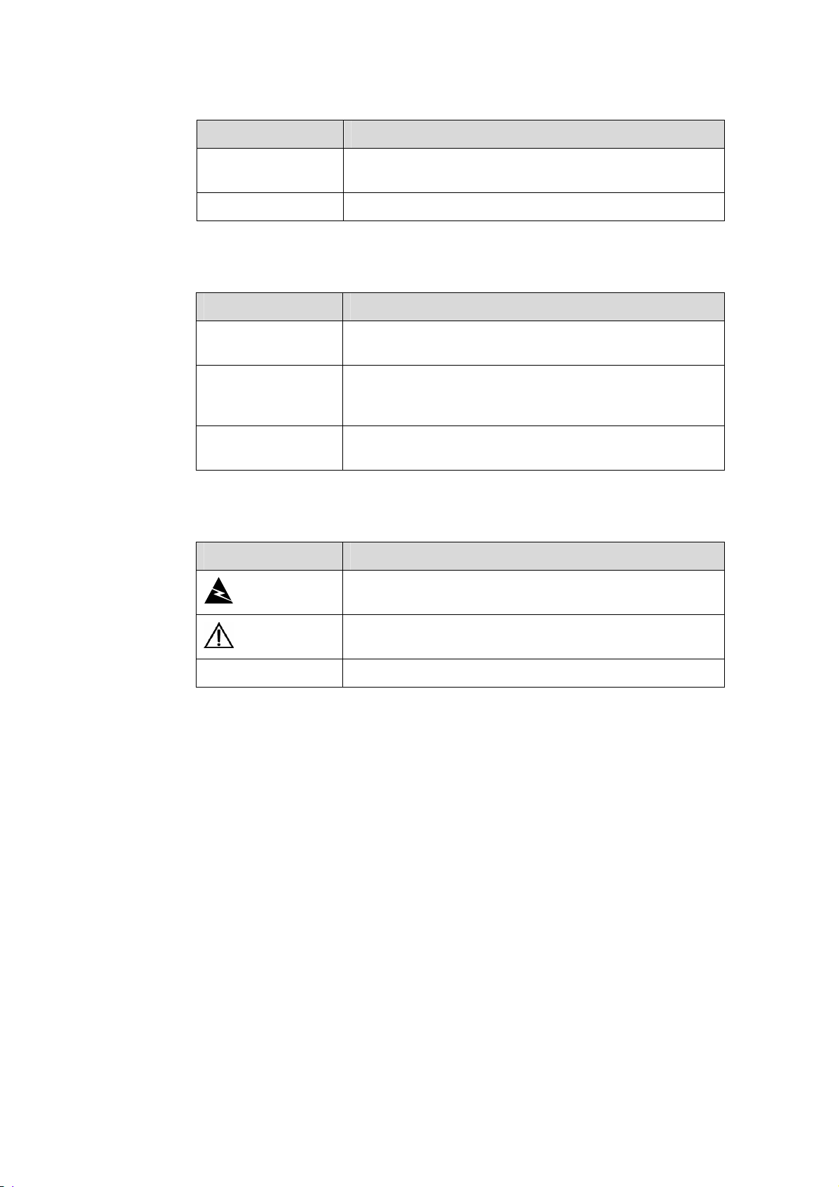
III. Symbols
Convention Description
Warning
Caution
Note Means a complementary description.
Environmental Protection
This product has been designed to comply with the requirements on environmental
protection. For the proper storage, use and disposal of this product, national laws and
regulations must be observed.
Means reader be extremely careful. Improper operation
may cause bodily injury.
Means reader be careful. Improper operation may cause
data loss or damage to equipment.
Page 6

H3C SR6608/6604 Routers Installation Manual Table of Contents
Table of Contents
Chapter 1 Router Overview..........................................................................................................1-1
1.1 Introduction ........................................................................................................................ 1-1
1.2 Physical Description .......................................................................................................... 1-2
1.2.1 Front View ............................................................................................................... 1-2
1.2.2 Rear View................................................................................................................ 1-4
1.3 System Specifications........................................................................................................ 1-5
1.3.1 RPE-X1 ................................................................................................................... 1-5
1.3.2 FIP-100.................................................................................................................... 1-9
1.3.3 FIP-200.................................................................................................................. 1-13
1.3.4 Dimensions, Weight and LPU Slots ...................................................................... 1-16
1.3.5 Voltage and Current .............................................................................................. 1-16
1.3.6 Interface Modules.................................................................................................. 1-16
1.3.7 Fan Tray ................................................................................................................ 1-19
1.3.8 Operating environment.......................................................................................... 1-19
1.4 Components..................................................................................................................... 1-19
1.4.1 RPE-X1 ................................................................................................................. 1-19
1.4.2 FIP-100/FIP-200.................................................................................................... 1-28
1.4.3 Power Supply Module ........................................................................................... 1-36
1.4.4 Port Lightning Arrester (Optional) ......................................................................... 1-38
1.4.5 Power Lightning Arrester (Optional)...................................................................... 1-38
1.4.6 Signal Lightning Arrester (Optional)...................................................................... 1-39
1.4.7 System Software ................................................................................................... 1-39
i
Page 7

H3C SR6608/6604 Routers Installation Manual Chapter 1 Router Overview
Chapter 1 Router Overview
1.1 Introduction
The H3C SR6608 and SR6604 routers are high-performance service routers
developed by Hangzhou H3C Technologies Co., Ltd. (hereinafter referred to as H3C)
for enterprise networks and carrier-edge access. The SR6608 and SR6604 adopt two
route processing engine-X1s (RPE-X1s), two power modules, and a distributed
modular architecture. Abundant optional modules are available so that the two service
routers can have a powerful processing capability and support flexible configuration to
fully meet the requirements of enterprise networks and carrier networks. The SR6608
and SR6604 can work at the core layer of small- and medium-sized enterprise
networks or at the distribution layer and core layer of large-sized enterprise networks.
They can also work at the access layer of carrier networks or large enterprise networks.
With the high-performance microprocessor technology, advanced hardware
architecture and H3C proprietary Comware V5 platform, the SR6608 and SR6604
provide high service processing capabilities, good service scalability, and high reliability.
In addition, the SR6608 and SR6604 can work together with other H3C network
devices to provide full network solutions for carriers and departments in electric power,
finance, tax, public security, railway and education, as well as for medium- and
large-sized enterprises. The full compliance with national and international standards
ensures the interoperability with the products of other manufacturers at different layers.
The SR6608 and SR6604 support high-speed interface modules (HIMs) and provide a
bus processing capability of up to 10 Gbps, which can meet the high-speed
performance requirements of users. In addition, the SR6608 and SR6604 are
compatible with some multi-functional interface modules (MIMs) of the H3C AR/MSR
series routers to guarantee the smooth upgrade from narrowband access to broadband
access, improve the competitiveness, and protect existing investments. For easy
description, the term “device” is used throughout this document to refer to any SR6608
or SR6604 router if not otherwise specified.
1-1
Page 8
H3C SR6608/6604 Routers Installation Manual Chapter 1 Router Overview
1.2 Physical Description
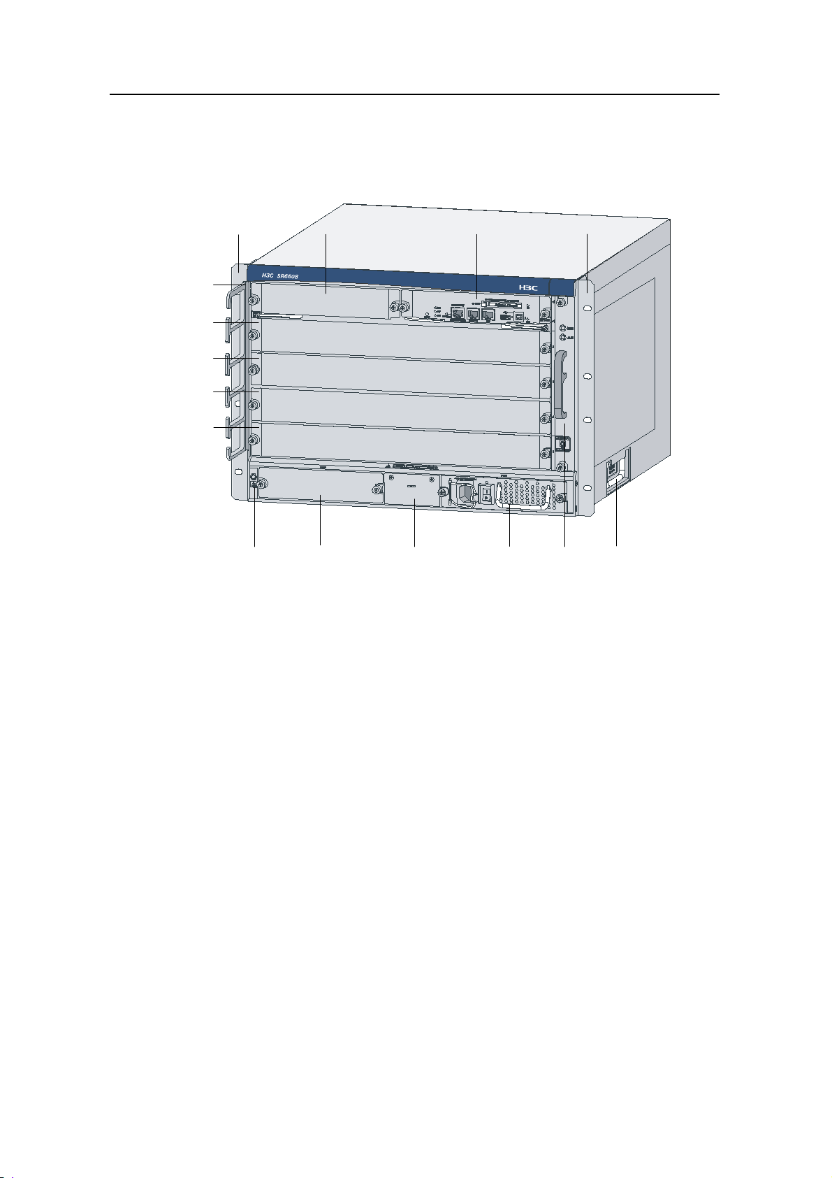
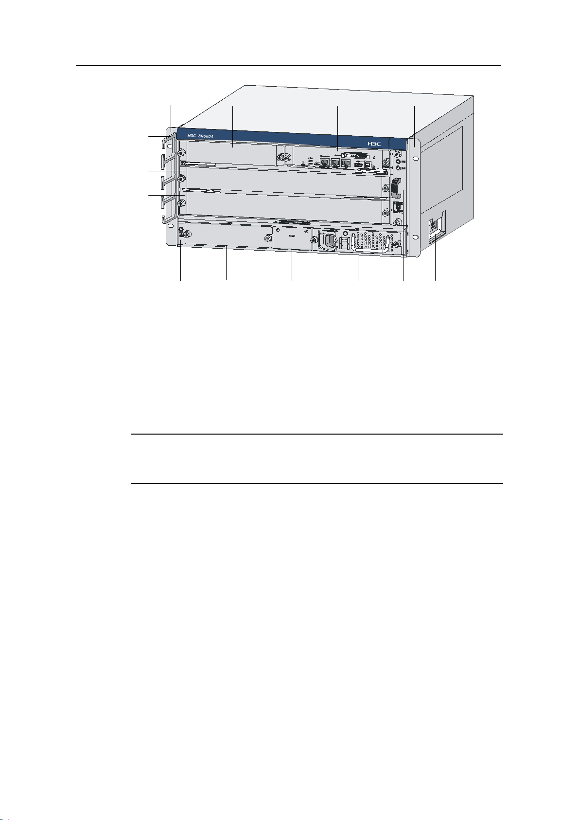
1.2.1 Front View
(1)
(15)
(14)
(13)
(12)
(11)
(1) Left mounting bracket (2) Blank panel for RPE-X1 (Slot 1)
(3) RPE-X1 (Slot 0) (4) Right mounting bracket
(5) Chassis handle (6) Fan tray
(7) AC power module (PWR 1)
(8) Blank panel for PoE power module (reserved PoE slot)
(9) Blank panel for power module (PWR 2) (10) ESD socket and silkscreen
(11) Blank panel for LPU (Slot 5) (12) Blank panel for LPU (Slot 4)
(13) Blank panel for LPU (Slot 3) (14) Blank panel for LPU (Slot 2)
(15) Cable management bracket
(2) (3) (4)
(7) (5)(8)(9)(10)
(6)
Figure 1-1 Front view of the SR6608
1-2
Page 9
H3C SR6608/6604 Routers Installation Manual Chapter 1 Router Overview
(1) (2) (3) (4)
(13)
(12)
(11)
(7) (5)(8)(9)(10) (6)
(1) Left mounting bracket (2) Blank panel for RPE-X1 (Slot 1)
(3) RPE-X1 (Slot 0) (4) Right mounting bracket
(5) Chassis handle (6) Fan tray
(7) AC power module (PWR 1)
(8) Blank panel for PoE power module (reserved PoE slot)
(9) Blank panel for power module (PWR 2) (10) ESD socket and silkscreen
(11) Blank panel for LPU (Slot 3) (12) Blank panel for LPU (Slot 2)
(13) Cable management bracket
Figure 1-2 Front view of the SR6604
Note:
Currently, the device does not support power over Ethernet (PoE).
1-3
Page 10
H3C SR6608/6604 Routers Installation Manual Chapter 1 Router Overview
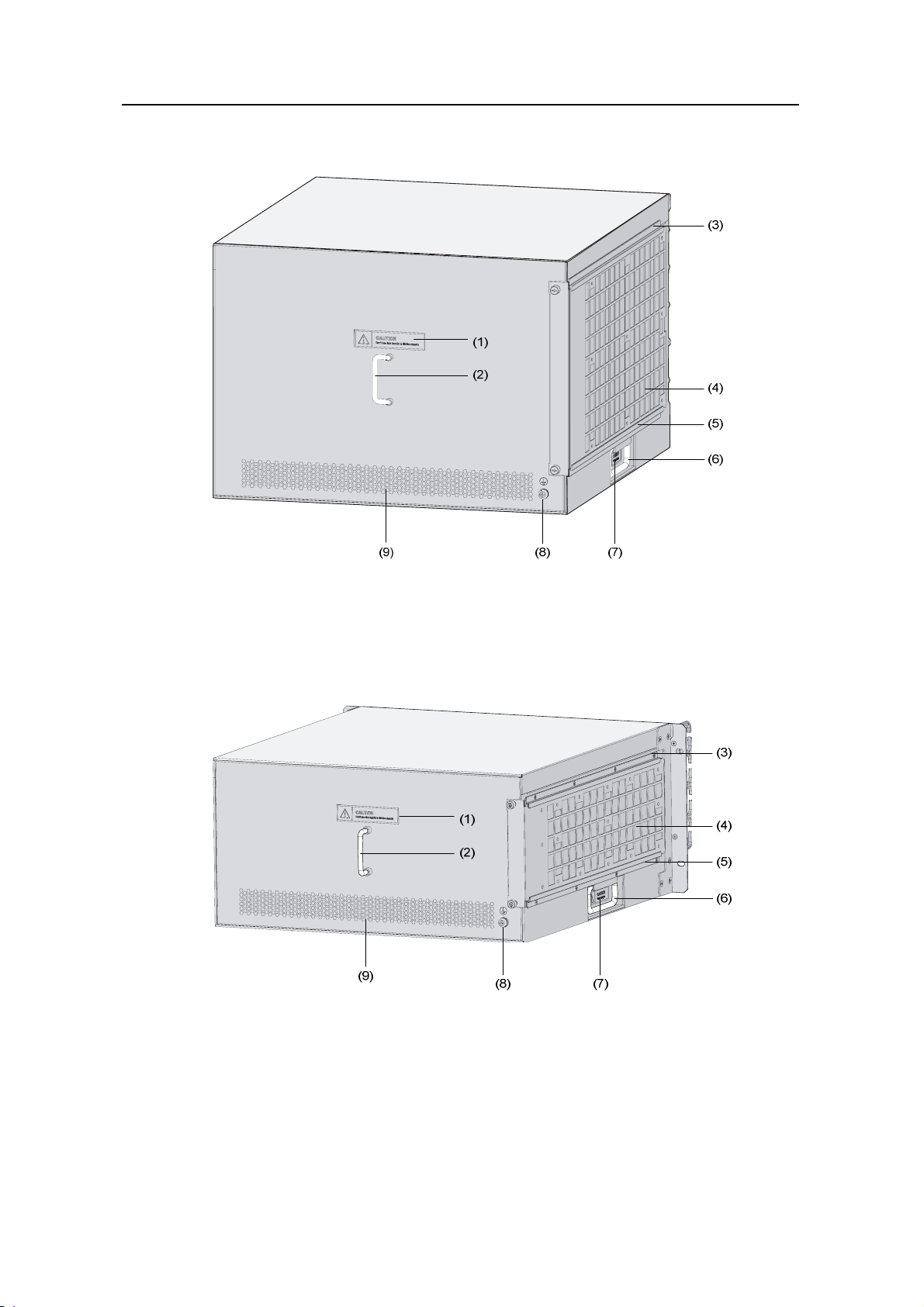
1.2.2 Rear View
(1) Warning label (2) Handle on the rear chassis panel
(3) Upper slide rail for the air filter (4) Air filter (optional)
(5) Lower slide rail for the air filter (6) Chassis handle
(7) Weight-bearing warning label (50 kg, namely, 110.2 lb.)
(8) Grounding screw and sign (9) Vents
Figure 1-3 Rear view of the SR6608
(1) Warning label (2) Handle on the rear chassis panel
(3) Upper slide rail for the air filter (optional) (4) Air filter (optional)
(5) Lower slide rail for the air filter (optional) (6) Chassis handle
(7) Weight-bearing warning label (50 kg, namely, 110.2 lb.)
(8) Grounding screw and sign (9) Vents
Figure 1-4 Rear view of the SR6604
1-4
Page 11
H3C SR6608/6604 Routers Installation Manual Chapter 1 Router Overview
Note:
Do not hold the handle indicated by (2) in Figure 1-3 on the rear chassis panel to move
the chassis because it is designed for the convenience of the rear chassis panel
removal, but not for bearing the chassis weight.
1.3 System Specifications
1.3.1 RPE-X1
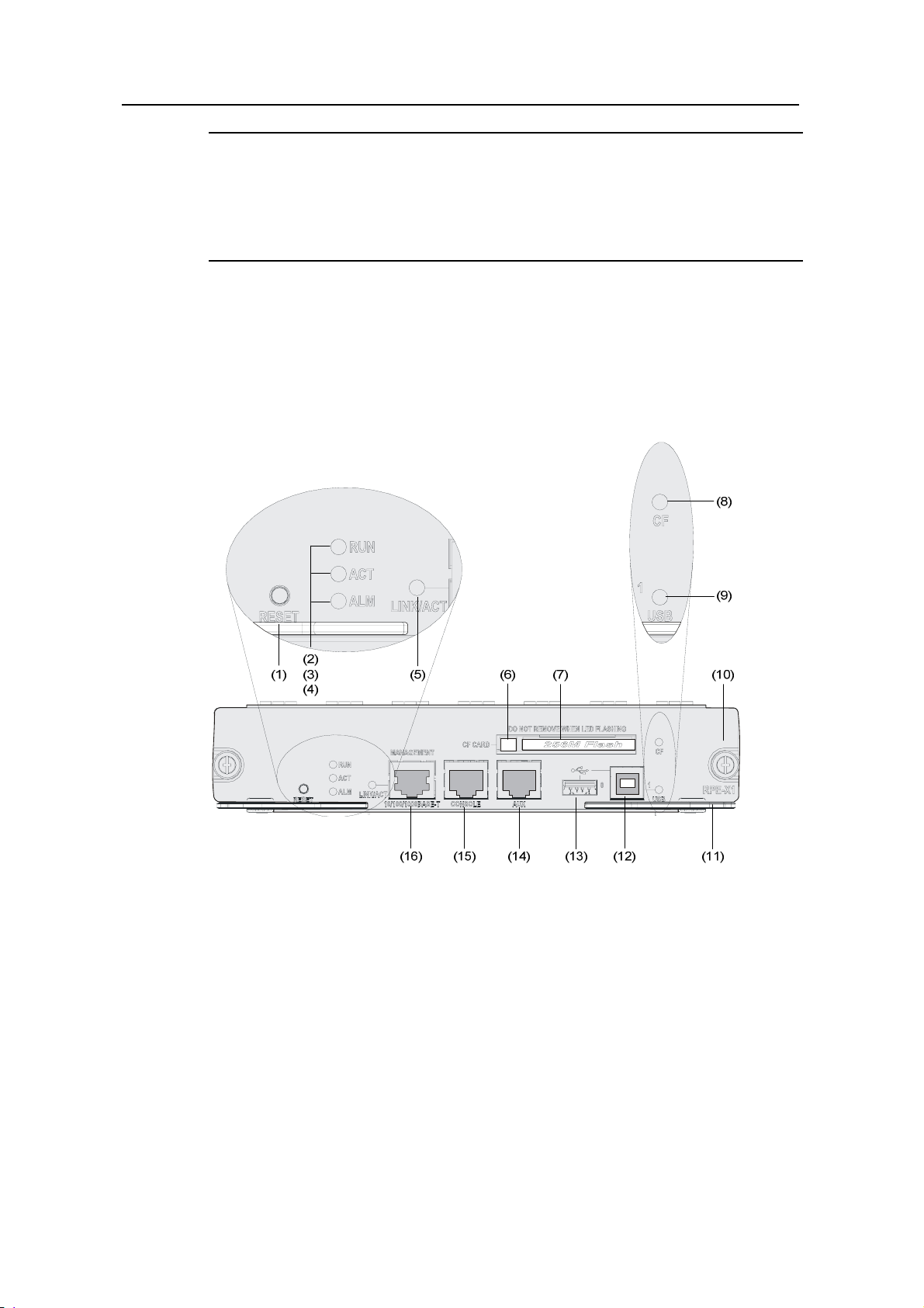
I. Front view
(1) RESET button (RESET) (2) Run LED (RUN)
(3) Active LED of the RPE-X1 (ACT) (4) Alarm LED (ALM)
(5) Link state/data reception & transmission LED (LINK/ACT)
(6) CF card eject button
(7) CF card slot (8) CF LED (CF)
(9) USB interface 1 LED (USB) (10) Captive screw
(11) Ejector lever (12) USB interface 1 (USB 1)
(13) USB interface 0 (USB 0) (14) AUX port (AUX)
15) Console port (CONSOLE)
(16) Management Ethernet interface (MANAGEMENT) (10/100/1000BASE-T)
Figure 1-5 Front view of RPE-X1
1-5
Page 12

H3C SR6608/6604 Routers Installation Manual Chapter 1 Router Overview
II. Technical specifications
Table 1-1 Technical specifications for the RPE-X1
Item Specification
Processor
Freescale MPC8548E 1GHz
Processor cores 1
Flash 4 MB
DDR2 SDRAM
Memory type and size
NVRAM
Console port
AUX port
Management Ethernet
interface
CF card
1 GB (default, one memory module)
2 GB (maximum)
128 KB
1 (9600 bps to 115200 bps, 9600 bps by default)
1 (9600 bps to 115200 bps, 9600 bps by default)
1 (10Base-T/100Base-TX/1000Base-T)
256 MB by default for the built-in CF card
256 MB, 512 MB, or 1 GB for an optional external
CF card
2 (USB 0: Type A connector, operating in the host
USB interfaces
Reset Button
mode; USB 1: Type B connector, operating in the
device mode)
1
Note:
Flash is used for storing the boot file—the BootWare program.
The memory is used for storing the data exchanged between the system and the
CPU.
The non-volatile random access memory (NVRAM) is used for storing the exception
information of the system during operation.
A CF card is used for storing the software system and configuration files of the
device.
1-6
Page 13
H3C SR6608/6604 Routers Installation Manual Chapter 1 Router Overview
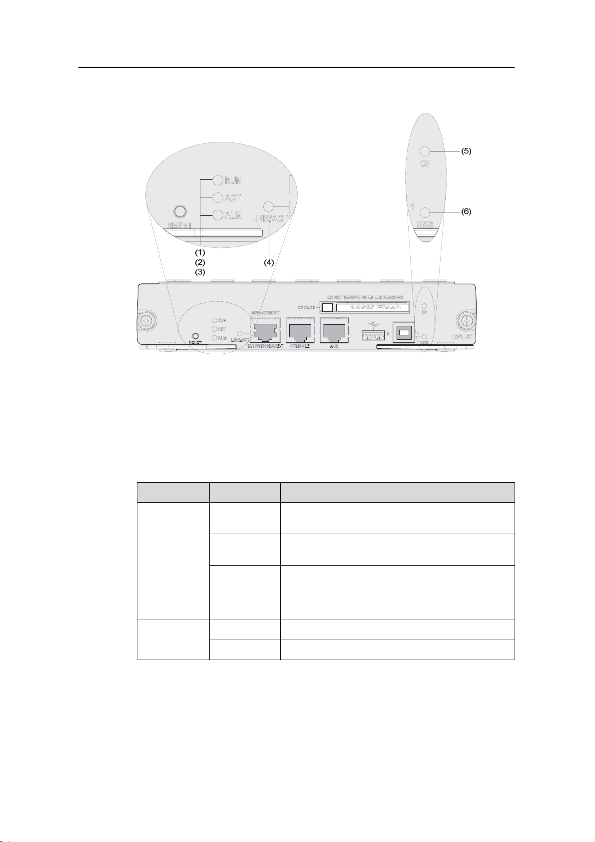
III. LEDs
(1) Run LED (RUN) (2) Active LED of the RPE-X1 (ACT)
(3) Alarm LED (ALM)
(4) Ethernet link state/data reception & transmission LED (LINK/ACT)
(5) CF LED (CF) (6) USB interface 1 LED (USB)
Figure 1-6 LEDs on the RPE-X1
1) Device LEDs
Table 1-2 Description of the device LEDs
LED Status Meaning
No power input is available, or the RPE-X1 has
failed.
The RPE-X1 is operating normally.
RUN (green)
Off
Slow blinking
(1 Hz)
The application software is being loaded (in this
Fast blinking
(8 Hz)
case, never power off the device or hot-swap the
RPE-X1; otherwise the RPE-X1 may be damaged),
or the RPE-X1 is not working.
ACT (green)
Off
On
The RPE-X1 is in the standby state.
The RPE-X1 is in the active state.
1-7
Page 14
H3C SR6608/6604 Routers Installation Manual Chapter 1 Router Overview
LED Status Meaning
The system is operating normally and there is no
alarm.
A fault has occurred to the system. In this state,
you need to check the system log immediately.
A critical fault has occurred to the system. In this
state, you need to handle the fault immediately.
ALM (red)
Off
On
Fast blinking
(8 Hz)
2) Management Ethernet interface LED
Table 1-3 Description of the management Ethernet interface LED
LED Status Meaning
Solid yellow A 10/100 Mbps link is present.
LINK/ACT
(yellow/green)
Solid green A 1000 Mbps link is present.
Blinking
yellow
Blinking
green
Data is being received or transmitted at a rate of
10/100 Mbps.
Data is being received or transmitted at a rate of
1000 Mbps.
3) USB 1 LED
Table 1-4 Description of the USB 1 LED
LED Status Meaning
Off
No host is connected to the device-mode USB
interface.
A host is connected to the device-mode USB
USB (green)
On
interface. The USB cable can be unplug in this
state.
Data is being transmitted or received through the
Blinking
device-mode USB interface. In this state, do not
unplug the USB cable.
4) CF LED
1-8
Page 15

H3C SR6608/6604 Routers Installation Manual Chapter 1 Router Overview
Table 1-5 Description of the CF LED
LED Status Meaning
CF (green)
Note:
Do not remove the CF card when the CF LED is blinking. Otherwise, the file system on
the CF card will be damaged.
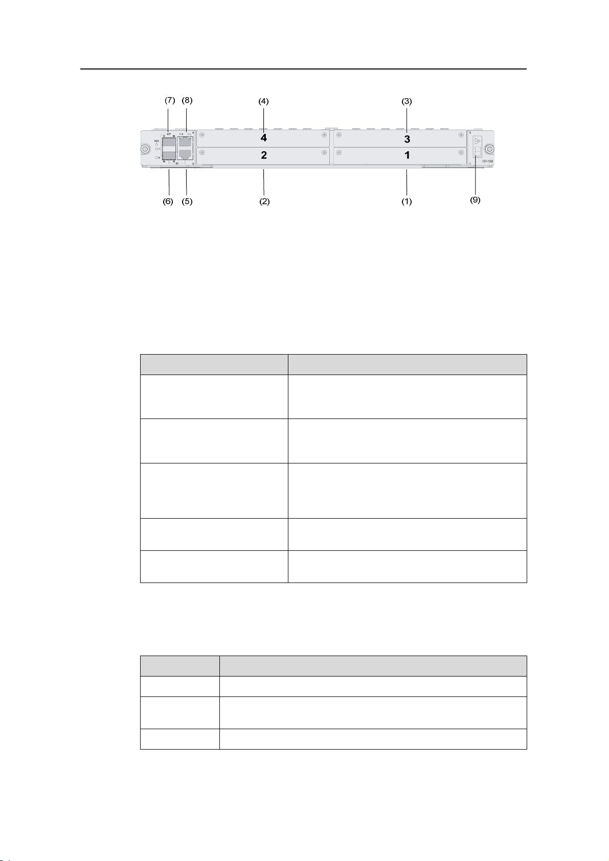
1.3.2 FIP-100
I. Introduction
Flexible interface platform-100 (FIP-100) is a type of line processing unit (LPU) that
supports H3C legacy multifunctional interface modules (MIMs). FIP-100 can be
inserted in slot 2, 3, 4, or 5 of the SR6608 or slot 2 or 3 of the SR6604. FIP-100 provides
two GigabitEthernet (GE) Combo interfaces and supports four MIMs at the same time.
FIP-100 is hot-swappable.
Off
On
Blinking
No CF card is present or the CF card is not
recognizable.
A CF card is in position and has been detected.
The system is accessing the CF card. In this state,
do not remove the CF card.
Note:
FIP-100 and FIP-200 are called LPUs in general.
“Hot-swapping” a module refers to first using the remove slot slot-number [ subslot
subslot-number ] command to stop the module and then pulling it out manually, or
inserting the module into its slot without powering off the device. For details about
the remove slot command, refer to H3C SR66 Series Routers User Manual.
1-9
Page 16
H3C SR6608/6604 Routers Installation Manual Chapter 1 Router Overview
(1) Slot 1 (2) Slot 2
(3) Slot 3 (4) Slot 4
(5) 10/100/1000 Mbps electrical Ethernet interface 0
(6) 1000 Mbps optical Ethernet interface 0 (7) 1000 Mbps optical Ethernet interface 1
(8) 10/100/1000 Mbps electrical Ethernet interface 1
(9) OPEN BOOK sign
Figure 1-7 Front view of the FIP-100
"OPEN BOOK" sign – Refer to related sections when performing the following
operations:
Operation Reference
Section 8.5 “Installing and Removing an
Plug/unplug an FIP-100
FIP-100/FIP-200” in Chapter 8 “Maintaining
Hardware”
Section 8. 9 “Installing and Removing an HIM” and
Plug/unplug an HIM/MIM
section 8.10 “Installing and Removing an MIM” in
Chapter 8 “Maintaining Hardware”
Section 5.10.3 “Connecting the Management
Connect an Ethernet cable
Ethernet Interface” and section 5.10.4 “Connecting
Ethernet Cables” in Chapter 5 “Installing the
Router”
Plug/unplug an optical module
Connect an optical fiber
Section 5.10.5 “Connecting Interface Module
Cables” in Chapter 5 “Installing the Router”
Section 5.10.5 “Connecting Interface Module
Cables” in Chapter 5 “Installing the Router”
II. Technical specifications
Table 1-6 Technical specifications for FIP-100
Item Specification
Processor
Processor
cores
Freescale MPC8548E 1GHz
1
Flash 4 MB
1-10
Page 17

H3C SR6608/6604 Routers Installation Manual Chapter 1 Router Overview
Item Specification
Memory type
and size
512 MB (default, one 512 MB memory module)
2 GB (maximum)
NVRAM 128 KB
DDR2 SDRAM
2
Two electrical
Combo
interfaces
interfaces
(automatic
MDI/MDI-X)
Two optical
HIM
MIM
Hardware
encryption
interfaces
Not supported
Four MIMs supported at the same time
Supported
Note:
10 Mbps, half/full-duplex
100 Mbps, half/full-duplex
1000 Mbps, full-duplex
1000 Mbps, full-duplex
If you need to install two memory modules, make sure they are of the same type and
size.
For a Combo interface, the default operating interface is the electrical interface.
For a Combo interface, you can use either the electrical Ethernet interface or the
optical Ethernet interface. You can use the combo enable { copper | fiber }
command in interface view to switch between the optical and electrical interfaces.
For details about the combo enable { copper | fiber } command, refer to H3C SR 66
Series Routers User Manual.
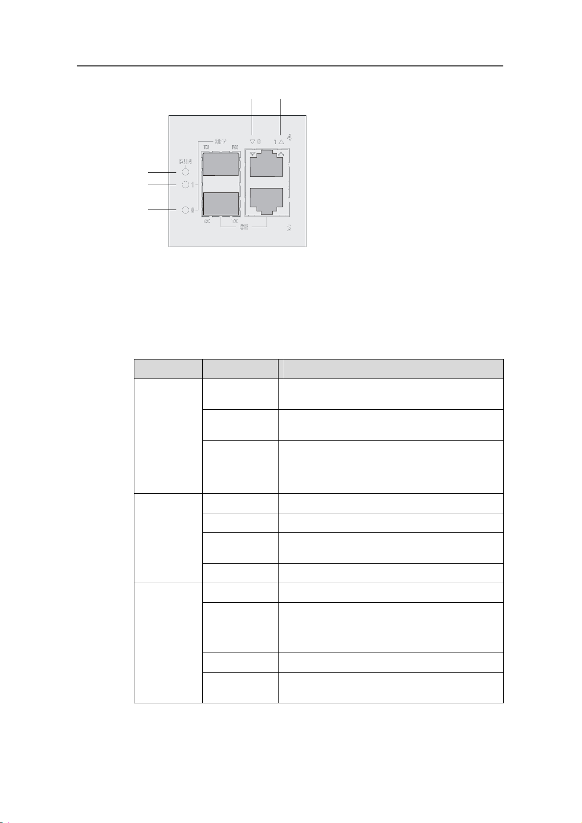
III. LEDs
FIP-100 provides five LEDs: RUN, SFP1, SFP0, GE0, and GE1. Table 1-7 describes
the LEDs.
1-11
Page 18
H3C SR6608/6604 Routers Installation Manual Chapter 1 Router Overview
(1) (2)
(5)
(4)
(3)
(1) LED for 10/100/1000 Mbps electrical Ethernet interface 0
(2) LED for 10/100/1000 Mbps electrical Ethernet interface 1
(3) 1000 Mbps optical Ethernet interface LED (SFP0)
(4) 1000 Mbps optical Ethernet interface LED (SFP1)
(5) Run LED (RUN)
Figure 1-8 FIP-100 LEDs
Table 1-7 Description of FIP-100 LEDs
LED Status Meaning
No power input is available or the FIP-100 has
failed.
The FIP100 is working normally.
RUN (green)
Off
Slow blinking
(1 Hz)
Application software is being loaded (in this case,
Fast blinking (8
Hz)
never power off the device or hot-swap the
FIP100; otherwise the FIP100 may be damaged)
or FIP-100 is not working.
SFP0 to
Off
Solid green
No optical link is present.
An optical link is present.
SFP1
(yellow/gree
n)
Blinking green
Solid yellow
Off
Solid green
Data is being sent or received at a rate of 1000
Mbps.
The optical transceiver failed to be detected.
No link is present.
A 1000 Mbps link is present.
GE0 to GE1
(yellow/gree
n)
Blinking green
Solid yellow
Blinking yellow
Data is being received or transmitted at a rate of
1000 Mbps.
A 10/100 Mbps link is present.
Data is being received or transmitted at a rate of
10/100 Mbps.
1-12
Page 19
H3C SR6608/6604 Routers Installation Manual Chapter 1 Router Overview
IV. Slots
FIP-100 provides four MIM slots for some H3C legacy MIMs.
The MIM slots on FIP-100 are numbered 1 to 4 from the bottom up and from right to left,
as shown in
Figure 1-9.
(1) Interface module slot 1 (2) Interface module slot 2
(3) Interface module slot 3 (4) Interface module slot 4
Figure 1-9 Interface module slots on FIP-100
Note:
The numbers 1 through 4 in Figure 1-9 represent Slot 1 through Slot 4 respectively.
Actually, these numbers are not silk-screened on an FIP-100.
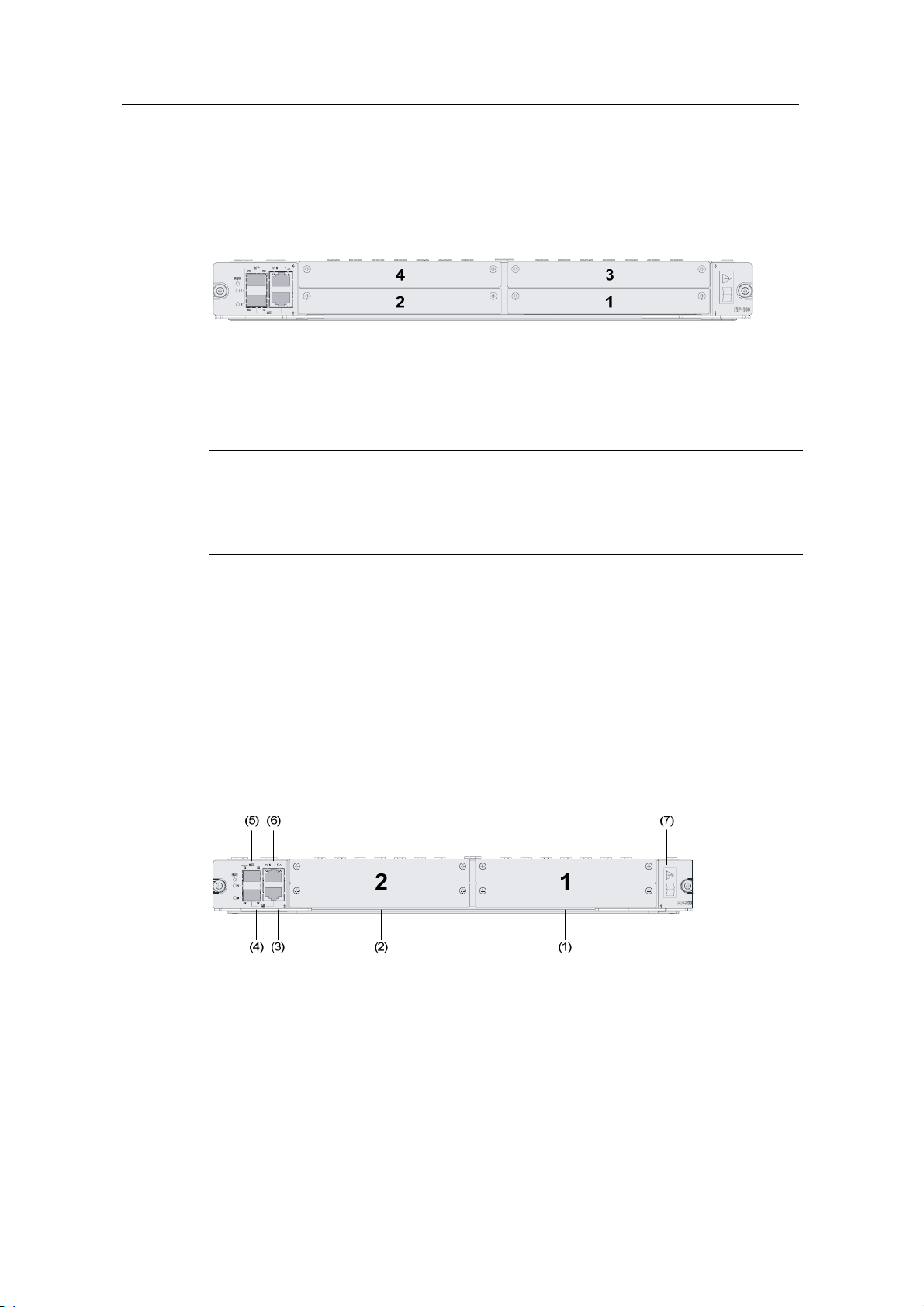
1.3.3 FIP-200
I. Introduction
Flexible interface platform-200 (FIP-200), another type LPU of the device, provides a
high-speed service processing capability. FIP-200 supports SR66 series HIMs and
some H3C legacy MIMs and provides two Combo interfaces. In consideration of the
smooth upgrade requirements, FIP-200 supports two HIMs or two MIMs, or intermixing
of an HIM and an MIM. FIP-200 is hot-swappable.
(1) Slot 1
(2) Slot 2
(3) 10/100/1000 Mbps electrical Ethernet interface 0
(4) 1000 Mbps optical Ethernet interface 0
(5) 1000 Mbps optical Ethernet interface 1
(6) 10/100/1000 Mbps electrical Ethernet interface 1
(7) OPEN BOOK sign
Figure 1-10 Front view of FIP-200
1-13
Page 20
H3C SR6608/6604 Routers Installation Manual Chapter 1 Router Overview
Note:
"OPEN BOOK" sign – Refer to related sections when performing the following
operations on FIP-200:
Plugging/unplugging an FIP-200
Plugging/unplugging an HIM/MIM
Connecting an Ethernet cable
Plugging/unplugging an optical module
Connecting an optical fiber
II. Technical specifications
Table 1-8 Technical specifications for FIP-200
Item Specifications
Processor
Multi-core MIPS CPU, 1 GHz
Processor cores 8
Flash 4 MB
DDR2 SDRAM
Memory type and
size
1 GB (default, two 512 MB memory modules)
2 GB (maximum)
1.5 GB not supported
NVRAM 128 KB
2
Two electrical
interfaces (automatic
Combo interfaces
MDI/MDI-X)
Two optical
HIMs
MIMs
interfaces
2
2
10 Mbps, half/full-duplex
100 Mbps, half/full-duplex
1000 Mbps, full-duplex
1000 Mbps, full-duplex
Hardware
encryption
Supported
1-14
Page 21
H3C SR6608/6604 Routers Installation Manual Chapter 1 Router Overview
Note:
Memory modules must be used in pairs. Make sure they are of the same type and
size.
For a Combo interface, the default operating interface is the electrical interface.
For a Combo interface, you can use either the electrical Ethernet interface or the
optical Ethernet interface. You can use the combo enable { copper | fiber }
command in interface view to switch between the optical and electrical interfaces.
For details about the combo enable { copper | fiber } command, refer to H3C SR 66
Series Routers User Manual.
III. LEDs
The LEDs on FIP-200 have the same meanings as those on FIP-100. See Table 1-7.
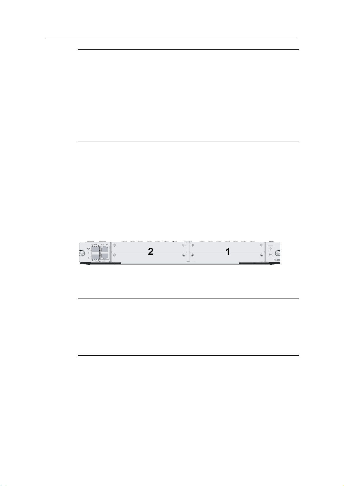
IV. Slots
An FIP-200 can be inserted in slot 2, 3, 4, or 5 of the SR6608 and slot 2 or 3 of the
SR6604.
The interface module slots on FIP-200 are numbered 1 and 2 from right to left, as
shown in
Figure 1-11.
Figure 1-11 Interface module slots on FIP-200
Note:
The numbers 1 through 2 in Figure 1-11 represent Slot 1 and Slot 2 respectively.
Actually, these numbers are not silk-screened on an FIP-200.
You can insert an MIM only at the bottom of an interface module slot of FIP-200
because only the bottom of the slot has a connector.
1-15
Page 22
H3C SR6608/6604 Routers Installation Manual Chapter 1 Router Overview
1.3.4 Dimensions, Weight and LPU Slots
Table 1-9 Dimensions, weight and LPU slots
Item
Dimensions without feet
and mounting brackets (H
× W × D)
Weight (full configuration) 50 kg (110.23 lb.) 38 kg (83.77 lb.)
LPU slots 4 2
1.3.5 Voltage and Current
Table 1-10 Voltage and current specifications
Item Specification
Rated voltage range
Maximum input current
Specification
SR6608 SR6604
308 × 476 × 436 mm
(12.13 × 18.74 × 17.17 in.)
AC powered: 100 VAC to 240 VAC; 50 Hz or 60 Hz
DC powered: –48 VDC to –60 VDC
AC powered: 10 A
DC powered: 25 A
219.5 × 436 × 480 mm
(8.64 × 17.2 × 18.90 in.)
Maximum power
1.3.6 Interface Modules
The SR6608 provides four LPU slots and the SR6604 provides two LPU slots. With full
configuration of FIP-100s or FIP-200s, the number of HIMs and MIMs supported at the
same time are listed in the following table.
Table 1-11 Interface modules supported with full configuration of FIP-100s or FIP-200s
Device
SR6608
SR6604
Interface
module
HIM — 8
MIM 16 8
HIM — 4
MIM 8 4
650 W
FIP-100 FIP-200
1-16
Page 23

H3C SR6608/6604 Routers Installation Manual Chapter 1 Router Overview
Note:
FIP-100 supports only MIMs.
FIP-200 supports both HIMs and MIMs and also intermixing of these two types of
modules.
Currently, the device supports the following interface modules.
Table 1-12 Interface modules supported on the device
Interface
Modules
HIM
Module name Description
8FE
8GBE
4GBE
CL2P
CL1P
CLS2P
CLS1P
MSP4P
8-port 100 Mbps electrical Ethernet interface
module
8-port 1000 Mbps electrical Ethernet interface
module (WAN)
4-port 1000 Mbps electrical Ethernet interface
module (WAN)
2-port 155 Mbps channelized POS interface
module (SFP)
1-port 155 Mbps channelized POS interface
module (SFP)
2-port 155 Mbps channelized E3/T3 POS
interface module (SFP)
1-port 155 Mbps channelized E3/T3 POS
interface module (SFP)
4-port multi-rate (155 or 622 Mbps)
non-channelized POS interface module
PS1P 1-port 2.5 Gbps POS interface module (SFP)
4GBP 4-port GE optical interface module (SFP)
1-17
Page 24

H3C SR6608/6604 Routers Installation Manual Chapter 1 Router Overview
Interface
Modules
MIM
Module name Description
1ATM-OC3MM
1ATM-OC3SM
1ATM-OC3SML
2SAE
4SAE
8SAE
2GBE
1-port 155 Mbps ATM multi-mode optical
interface module
1-port 155 Mbps ATM single-mode optical
interface module
1-port 155 Mbps ATM single-mode long-haul
optical interface module
2-port enhanced synchronous/asynchronous
serial interface module
4-port enhanced synchronous/asynchronous
serial interface module
8-port enhanced synchronous/asynchronous
serial interface module
2-port 10/100/1000M Base-T electrical interface
(RJ-45) module
8E1 (75) 8-port E1/CE1/PRI interface module (75 ohms)
8E1 (75)-F
8-port non-channelized E1 interface module (75
ohms)
POS
1-port POS interface module with the interface
transmission rate STM-1/OC-3 (155.52 Mbps)
Note:
2SAE, 4SAE, and 8SAE do not support the asynchronous serial interface feature.
8E1 (75)/8E1 (75)-F does not support the ISDN PRI feature.
POS interface modules are sold together with optical modules. Currently, the optical
modules sold together with POS interface modules include multi-mode SFP module
(2 km or 1.24 miles), single-mode SFP module (15 km or 9.32 miles), and
single-mode SFP module (40 km or 24.86 miles).
For the specifications and functions of HIMs and MIMs, refer to Chapter 2 “Interface
Modules”.
For the installation and removal of HIMs and MIMs, refer to Chapter 8 “Maintaining
Hardware”.
HIMs and MIMs are hot-swappable.
1-18
Page 25
H3C SR6608/6604 Routers Installation Manual Chapter 1 Router Overview
1.3.7 Fan Tray
Table 1-13 Technical specifications for the fan tray
Fan (built-in)
SR6608 SR6604
Rated voltage
Total fan power
consumption
Fay tray dimensions
(H × W × D)
Table 1-14 Description of fan tray LEDs
LED Status Meaning
RUN (green) On
ALM (red)
Note:
The device supports automatic fan speed adjustment and hot-swapping of the fan tray.
On
12 VDC
30 W
228 × 31 × 413.3 mm (8.98
×1.22 × 16.27 in.)
The fan tray is working normally.
The fan tray is faulty.
Specification
136.4 × 31 × 427.8 mm
(5.37 ×1.22 × 16.84 in.)
1.3.8 Operating environment
Table 1-15 Operating environment specifications
Item Specification
Operating temperature
Operating humidity
Altitude
1.4 Components
1.4.1 RPE-X1
I. Processor
The RPE-X1s use Freescale MPC8548E 1 GHz processors as route processing
engines.
0°C to 45°C (32°F to 113°F)
10% to 95%, noncondensing
–60 m to +4 km (–196.85 ft. to +2.49 miles)
1-19
Page 26

H3C SR6608/6604 Routers Installation Manual Chapter 1 Router Overview
II. Flash
The Flash size is 4 MB, of which 1 MB is used for storing the boot file—BootWare and
the remaining space for BootWare backup and important system parameters.
III. Memory module
The memory module is used for storing the data exchanged between the system and
the CPU. The default memory size of the RPE-X1 is one GB memory and the maximum
memory size is two GB. One RPE-X1 provides two memory slots in which you can
insert two DDR2 SDRAMs of different sizes.
The DDR2 SDRAMs for the RPE-X1 have two sizes:
DDR2 SDRAM-512MB
DDR2 SDRAM-1GB
IV. NVRAM
The NVRAM is 128 KB in size and is used for storing exception information of the
system during operation.
V. CF card
1) Introduction
A compact flash (CF) card is used for storing logs, host files, and configuration files.
The device is equipped with a built-in 256 MB CF card, which is identified with cfa0. In
addition, the device provides an external CF card slot to expand the local storage space.
A CF card inserted into the external CF card slot is identified with cfb0.
The CF cards supported by the device are available in three sizes:
256 MB
512 MB
1 GB
Caution:
Use CF cards provided by H3C only. The device may be incompatible with other CF
cards.
2) CF card and slot
1-20
Page 27

H3C SR6608/6604 Routers Installation Manual Chapter 1 Router Overview
(1) (2) (3)
(1) Eject button (CF card) (2) CF card slot
(3) CF LED (CF)
Figure 1-12 CF card and slot
3) CF LED
For the description of the CF LED, see
Table 1-5.
Caution:
The CF card is hot-swappable. When the CF LED is blinking, do not unplug the CF card.
Otherwise, the file system on the CF card will be damaged.
VI. Console port
1) Introduction
The device provides an RS232 asynchronous serial console port that can be
connected to a computer for system debugging, configuration, maintenance,
management, and host software loading.
2) Technical specifications for the console port
Table 1-16 Technical specifications for the console port
Item Specification
Connector
Compliant standard
Baud rate
Transmission Distance
Services
RJ-45
Asynchronous EIA/TIA-232
9600 bps to 115200 bps
9600 bps (default)
≤ 15 m (49.21 ft.)
Connection to an ASCII terminal
Connection to the serial interface of a local PC to
run the terminal emulation program
Command line interface (CLI)
1-21
Page 28
H3C SR6608/6604 Routers Installation Manual Chapter 1 Router Overview
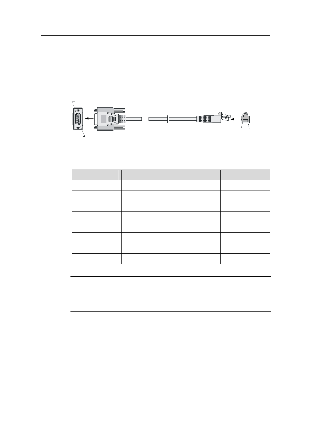
3) Console cable
The console cable is an 8-core shielded cable. The RJ-45 connector at one end of the
cable is for the console port on the router, and the DB-9 female connector at the other
end is for the serial port on a configuration terminal.
Figure 1-13 illustrates the console cable.
A
Pos.9
Pos.1
A
W
B
B
Pos.8Pos.1
Figure 1-13 Console cable
Table 1-17 Console cable connector pinouts
RJ-45 pin Signal direction DB-9 pin Signal
1
2
3
4
8 CTS
6 DSR
2 RXD
1 DCD
5 — 5 GND
6
7
8
3 TXD
4 DTR
7 RTS
Note:
For the connection of the console cable, refer to section 5.10.1 “Connecting the
Console Cable” in Chapter 5 “Installing the Router”.
VII. AUX port
1) Introduction
The AUX port is an RS232 asynchronous serial interface used for remote configuration
or dialup backup. You need to connect the local modem to the remote modem through
PSTN and then to the remote device for remote system debugging, configuration,
maintenance, and management. In the event that the console port fails, the AUX port
can be connected to a terminal as a backup port of the console port. For details, refer to
1-22
Page 29
H3C SR6608/6604 Routers Installation Manual Chapter 1 Router Overview
section 9.7 “Using the Port AUX as Backup Console Port” in Chapter 9
“Troubleshooting”.
2) Technical specifications for the AUX port
Table 1-18 Technical specifications for the AUX port
Item Specification
Connector
Compliant standard
Baud rate
RJ-45
Asynchronous EIA/TIA-232
9600 bps to 115200 bps
9600 bps (default)
Used to connect the serial interface of a remote PC
Services
through a pair of modems to establish a dial-up connection
with the PC
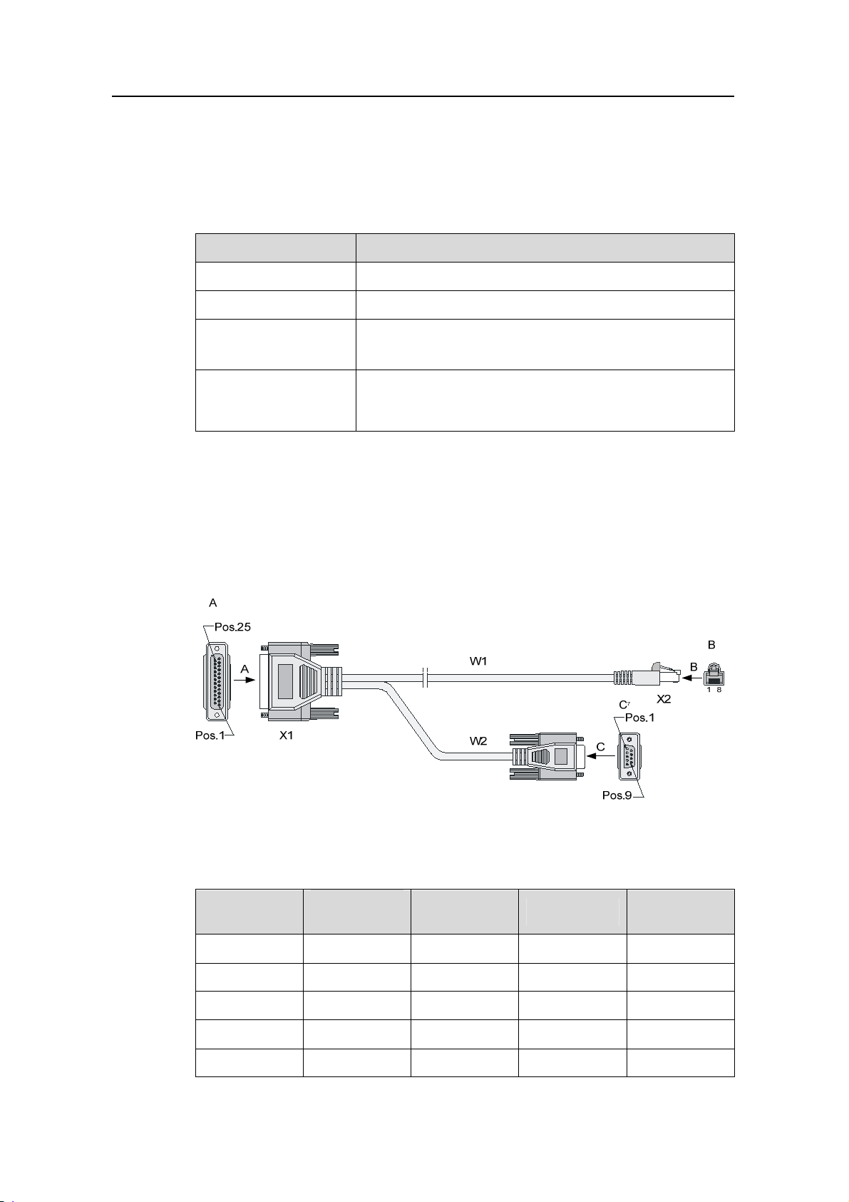
3) AUX cable
The AUX cable is an 8-core shielded cable. At one end of the cable is an RJ-45
connector, which is connected to the AUX port on the router. At the other end are a
DB-9 (male) connector and a DB-25 (male) connector, of which you can select one to
the serial port on a modem as needed.
Figure 1-14 AUX cable connectors
Table 1-19 AUX cable connector pinouts
RJ-45 pin
1
2
3
4
Signal
direction
DB-25 pin DB-9 pin Signal
4 7 RTS
20 4 DTR
2 3 TXD
8 1 DCD
5 — 7 5 GND
1-23
Page 30
H3C SR6608/6604 Routers Installation Manual Chapter 1 Router Overview
RJ-45 pin
6
7
8
Signal
direction
DB-25 pin DB-9 pin Signal
3 2 RXD
6 6 DSR
5 8 CTS
Note:
For the connection of the AUX cable, refer to section 5.10.2 “Connecting the AUX Port
to a Modem” in Chapter 5 “Installing the Router”.
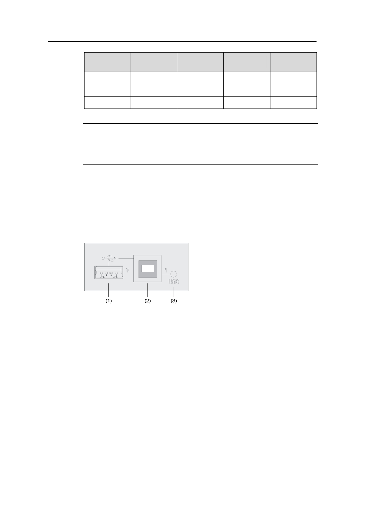
VIII. USB interfaces
Universal serial bus (USB) interfaces can connect multiple types of devices and provide
a higher data transfer rate than common parallel interfaces and serial interfaces.
The device fully supports USB 1.1. The USB interfaces of the device allow for
convenient storage.
(1) USB interface 0 (2) USB interface 1
(3) USB interface 1 LED
Figure 1-15 USB interfaces
1) USB 0
USB interface 0 on the device is a USB 1.1-compliant type-A interface. USB interface 0
can be connected to an external USB storage device to expand the router’s storage
space for storing files and logs and facilitate file transfer.
Insert and remove a USB storage device correctly. Otherwise, the software, hardware
and file system of the USB storage device may get damaged.
After you insert a USB storage device and information is displayed on the terminal,
prompting the USB storage device is inserted into the device, the LED on the USB
storage device will be on.
When the LED on the USB storage device is blinking, do not remove the USB
storage device. Before removing the USB storage device, execute the umount
usba0: command in user view to unmount the USB storage device. If information
1-24
Page 31

H3C SR6608/6604 Routers Installation Manual Chapter 1 Router Overview
is displayed on the terminal, prompting the USB storage device is successfully
unmounted, you can remove the USB storage device. After the USB storage
device is removed, information will also be displayed on the terminal, prompting
the USB storage device has been removed.
Note:
The device only supports the USB storage devices provided by H3C and may be
incompatible with those from other manufacturers.
For details about the umount command, refer to H3C SR66 Series Routers User
Manual.
2) USB 1 and LED
USB interface 1 on the device is a USB 1.1-compliant type-B interface. USB interface 1
can be connected to a host device through a standard USB cable. The host recognizes
the device as an external storage device so that you can access the internal CF card
quickly and perform file operations on it. For the description of the USB 1 status LED,
Table 1-4 on page 1-8.
see
IX. Management Ethernet interface
The management Ethernet interface is a 10Base-T/100Base-TX/1000Base-T RJ-45
interface. It allows you to upgrade software and manage the router through a network
management server without using any service interface of the router. The management
Ethernet interface is used only for managing the device and it has no service
processing capabilities such as data forwarding.
Table 1-20 Technical specifications for the management Ethernet interface
Item Specification
Connector
Number of interfaces
Interface type
Frame format
RJ-45
1
Automatic MDI/MDI-X
Ethernet_II
Ethernet_SNAP
10 Mbps, half/full-duplex
Interface speed and duplex mode
100 Mbps, half/full-duplex
1000 Mbps, full-duplex
Interface cable and maximum
transmission distance
Straight-through or crossover cable,
Category-5 twisted pair with a maximum
transmission distance of 100 m (328.08 ft.)
1-25
Page 32

H3C SR6608/6604 Routers Installation Manual Chapter 1 Router Overview
Item Specification
Function
Used for router software upgrading and
network management
Note:
The media dependent interface (MDI) standard is typically used on the Ethernet
interface of network adapters. The media dependent interface crossover (MDI-X)
standard is typically used on hubs or LAN switches.
X. RESET button
To reset the current RPE-X1, you can press the RESET button.
If you press the RESET button when only one RPE-X1 is equipped, the whole
system will be reset.
If you want to perform an active-standby switchover when two RPE-X1s are
equipped, press the RESET button on the active RPE-X1. The system will
automatically switch the services to the standby RPE-X1, without interrupting the
ongoing services.
If you press the RESET button on the standby RPE-X1 when two RPE-X1s are
equipped, the standby RPE-X1 will be reset but the system operation will not be
affected.
The RUN LED goes off when the RPE-X1 is reset, flashes fast (at 8 Hz) when
BootWare is running, and flashes slowly (at 1 Hz) after the system is booted and
operates normally.
Note:
If you perform no save operation before resetting the router, the current system
configuration will not be saved after the router is reset.
Never press the RESET button when the RUN LED is blinking fast or when the
router is accessing the CF card or a USB storage device. Otherwise, the file system
of the router may be damaged.
XI. Clock
The device is designed with an internal clock module that provides the system time.
You can set the system time through a command line interface.
1-26
Page 33

H3C SR6608/6604 Routers Installation Manual Chapter 1 Router Overview
When a power failure occurs to the router, the clock module can continue working to
ensure the system time is correct next time the router boots. With the router powered
off, the clock module can work for at least 10 years.
When the router is powered on, note the following points:
Never replace the clock module battery.
The system time gets lost once the clock module battery is removed, and you
need to set the system time again through the command line interface. However,
the system time will still get lost after the router is powered off.
Note:
Use the clock datetime time date command in user view to set the system date and
time.
For the description of the clock datetime command, refer to H3C SR66 Series
Routers User Manual.
XII. Switchover between the active and standby RPE-X1s
The device can be equipped with two RPE-X1s. One is the active RPE-X1 and
operates in the master mode, and the other is the standby RPE-X1 and operates in the
slave mode. The configuration of the standby RPE-X1 is synchronized with that of the
active RPE-X1. Thus, in the event that the active RPE-X1 fails, the standby RPE-X1
immediately becomes the active RPE-X1 to ensure that the device works properly and
its configuration is synchronized with that of the original active RPE-X1. This process is
known as active-standby switchover.
An active-standby switchover occurs when:
The active RPE-X1 fails.
The active RPE-X1 is removed.
A remote switchover is performed through SNMP.
A manual switchover is performed.
The active-standby switchover process is as follows:
1) The standby RPE-X1 automatically connects and controls the system bus while
the original active RPE-X1 disconnects the system bus.
2) The standby RPE-X1 goes active whereas the original active RPE-X1
automatically reboots and goes standby.
You can use the slave switchover command to perform a manual active-standby
switchover. For details about the slave switchover command, refer to H3C SR66
Series Routers User Manual.
1-27
Page 34

H3C SR6608/6604 Routers Installation Manual Chapter 1 Router Overview
Caution:
The standby RPE-X1 does not support any system configuration commands.
Therefore, you cannot execute any commands on the standby RPE-X1 unless it
goes active.
When the standby RPE-X1 is started, the active RPE-X1 will initially synchronize the
standby RPE-X1. If you press Enter on the terminal during synchronization, the
system will prompt on the active and standby RPE-X1s that no command can be
entered. After the initial synchronization is completed, you can execute the
configuration commands on the active RPE-X1, and the standby RPE-X1 keeps
synchronized with the active RPE-X1 in real time way (the configuration on the
active RPE-X1 is copied to the standby RPE-X1).
Do not use centralized device–specific software to update the router that supports
the active-standby switchover feature. Otherwise, the router may become
unavailable.
1.4.2 FIP-100/FIP-200
I. Ethernet interface introduction
The FIP-100/FIP-200 of the device provides two Combo interfaces, each of which
consists of an electrical Ethernet interface and an optical Ethernet interface. The
default operating interface is the electrical Ethernet interface.
For the rate and duplex mode when the electrical Ethernet interface is operating,
Table 1-21.
see
Table 1-21 Rate and duplex mode when the electrical Ethernet interface is operating
10 Mbps
100 Mbps
1000 Mbps
Rate Duplex mode
Half/full-duplex auto-negotiation
Half/full-duplex auto-negotiation
Full-duplex
The electrical Ethernet interface LEDs are above the RJ-45 ports. The LEDs in triangle
and inverted triangle indicate the status of the lower and upper electrical Ethernet
interfaces, respectively. For the description of the electrical Ethernet interface LEDs,
Table 1-7.
see
The optical Ethernet interface supports 1000 Mbps in full-duplex mode. The
optical Ethernet interface LEDs are on the left of the two Combo interfaces and
use separate LEDs to indicate the status of the corresponding optical Ethernet
1-28
Page 35

H3C SR6608/6604 Routers Installation Manual Chapter 1 Router Overview
interfaces. For the description of the optical Ethernet interface LEDs, see Table
1-7.
(1) (2) (3) (4)
(9)
(8)
(7)
(5)(6)
(1) 1000 Mbps optical Ethernet interface (SFP1)
(2) 10/100/1000 Mbps electrical Ethernet interface (GE0) LED
(3) 10/100/1000 Mbps electrical Ethernet interface (GE1)
(4) 10/100/1000 Mbps electrical Ethernet interface (GE1) LED
(5) 10/100/1000 Mbps electrical Ethernet interface (GE0)
(6) 1000 Mbps optical Ethernet interface (SFP0)
(7) 1000 Mbps optical Ethernet interface (SFP0) LED
(8) 1000 Mbps optical Ethernet interface (SFP1) LED
(9) Run LED (RUN)
Figure 1-16 Combo interfaces on FIP-100/FIP-200
Note:
For a Combo interface, you can use either the electrical Ethernet interface or the optical
Ethernet interface. You can use the combo enable { copper | fiber } command in
interface view to switch between the optical and electrical Ethernet interfaces. For
details about the combo enable { copper | fiber } command, refer to H3C SR66 Series
Routers User Manual.
II. Technical specifications for Combo interfaces
Technical specifications for electrical Ethernet interfaces
Table 1-22 Technical specifications for electrical Ethernet interfaces
Item Specification
Connector
Interface type
1-29
RJ-45
Automatic MDI/MDI-X
Page 36

H3C SR6608/6604 Routers Installation Manual Chapter 1 Router Overview
Item Specification
Frame format
Rate and duplex mode
Ethernet_II
Ethernet_SNAP
10 Mbps, half/full-duplex
100 Mbps, half/full-duplex
1000 Mbps, full-duplex
Note:
The media dependent interface (MDI) is a typical Ethernet interface provided by
network adapters. The media dependent interface crossover (MDI-X) is commonly
found on hubs or LAN switches.
When 10/100 Mbps and half duplex/full duplex are specified for an electrical
Ethernet interface, the electrical Ethernet interface operates in the forced mode.
When 1000Mbps is specified or the rate and the duplex mode are not
simultaneously specified for an electrical Ethernet interface, the electrical Ethernet
interface operates in the auto-negotiation mode.
No matter whether an electrical Ethernet interface operates in the forced or
auto-negotiation mode, it supports automatic MDI/MDI-X.
Technical specifications for optical Ethernet interfaces
Table 1-23 Technical specifications for 1000 Mbps optical Ethernet interfaces
Item Specification
Connector
Compliant
standard
Optical
transm
it
power
Type
SFP/LC
802.3, 802.3u, and 802.3ab
Short-haul
multimode
optical
interface
module
(850 nm)
Medium-haul
single-mode
optical
interface
module
(1310 nm)
Long-haul
Optical
interface
module
(1310 nm)
Long-haul
optical
interface
module
(1550 nm)
Ultra-long
haul
optical
interface
module
Min –9.5 dBm –9 dBm –2 dBm –4 dBm –4 dBm
Max 0 dBm –3 dBm 5d Bm 1 dBm 2 dBm
Receiving
sensitivity
Central
wavelength
–17 dBm -20 dBm –23 dBm –21 dBm –22 dBm
850 nm 1310 nm 1310 nm 1550 nm 1550 nm
1-30
Page 37

H3C SR6608/6604 Routers Installation Manual Chapter 1 Router Overview
Item Specification
Fiber type
Maximum
transmission
distance
Operating
mode
62.5/125
μm
multimode
fiber
0.55 km
(0.34
miles)
1000 Mbps in full duplex mode
9/125 μm
single-mode
fiber
10 km (6.21
miles)
9/125 μm
single-mo
de fiber
40 km
(24.86
miles)
9/125 μm
single-mo
de fiber
40 km
(24.86
miles)
9/125 μm
single-mo
de fiber
70 km
(43.50
miles)
III. RJ-45 connector
The 10Base-T/100Base-TX/1000Base-T electrical Ethernet interfaces of the device
use RJ-45 connectors and support MDI/MDI-X auto-sensing. Category-5 twisted pair
cables are used for RJ-45 connectors.
Figure 1-17 shows the appearance of an RJ45
connector.
Figure 1-17 RJ-45 connector
IV. LC connector and SC connector
Optical fiber connectors are indispensable passive components in optical fiber
communication system. Their application enables the removable connection between
optical channels, which makes the optical system debugging and maintenance more
convenient and the transit dispatching of the system more flexible.
Some optical fiber connector types are as follows:
LC: square optical fiber connector of the push-pull snap-in type
SC: standard optical fiber connector
FC: round optical fiber connector with screw thread
ST: round plug-in optical fiber connector
MT-RJ: square transceiver optical fiber connector
1-31
Page 38

H3C SR6608/6604 Routers Installation Manual Chapter 1 Router Overview
Figure 1-18 LC connector
Figure 1-19 SC connector
Note:
Before using an optical fiber to connect a network device, verify that the optical fiber
connector matches the optical module.
Before connecting a fiber, make sure that the received optical power at the local end
does not exceed the upper threshold of the optical receive power of the optical
module. Otherwise, the optical module may be damaged.
V. Cable connecting a 1000 Mbps electrical Ethernet interface
Usually, you can use a category-5 twisted pair cable to connect a 1000 Mbps electrical
Ethernet interface.
Figure 1-20 shows an Ethernet cable.
Figure 1-20 Ethernet cable
Ethernet cables fall into the following two categories:
Standard cable: Also called straight-through cable. At both ends of a standard
cable, wires are crimped in the RJ-45 connectors in the same sequence. a
straight-through cable is used to connect a terminal (for example, PC or router) to
1-32
Page 39

H3C SR6608/6604 Routers Installation Manual Chapter 1 Router Overview
a hub or LAN Switch. The cables delivered with the router are straight-through
cables.
Crossover cable: At both ends of a crossover cable, wires are crimped in the
RJ-45 connectors in different sequences. A crossover cable is used to connect a
(for example, PC or router) to another terminal. You can make crossover cables by
yourself as needed.
Table 1-24 Straight-through cable connector pinouts
RJ-45 pin Signal
1 Tx+
2 Tx– Orange
Category-5
twisted pair
White
(Orange)
3 Rx+ White (Green)
4 — Blue
5 — White (Blue)
6 Rx– Green
Signal
direction
RJ-45 pin
1
2
3
— 4
— 5
6
7 — White (Brown) — 7
8 — Brown
— 8
Table 1-25 Crossover cable connector pinouts
RJ-45 pin
1 Tx+
Signal
direction
Category-5
twisted pair
White
(Orange)
Signal
direction
RJ-45 pin
3
2 Tx– Orange
3 Rx+ White (Green)
4 — Blue
5 — White (Blue)
6 Rx– Green
6
1
— 4
— 5
2
7 — White (Brown) — 7
8 — Brown
— 8
1-33
Page 40

H3C SR6608/6604 Routers Installation Manual Chapter 1 Router Overview
Note:
You can refer to the table above when distinguishing between or preparing these
two types of Ethernet cables.
When preparing Ethernet cables, please follow the chromatogram given in the table
to arrange the wires. Otherwise communication quality will be affected even if the
equipment at two ends are connected.
When preparing Ethernet cables, use shielded cables preferentially for
electromagnetic compatibility (EMC).
VI. Fiber connecting 1000 Mbps optical Ethernet interface
You can use a single-mode or multimode optical fiber to connect a 1000 Mbps optical
Ethernet interface to an Ethernet. You can select proper fibers for the installed
1000Base-X SFP modules (GE SFP for short). Since the optical interfaces on these
SFP modules use LC optical connectors, you must use fibers with LC connectors. All
SFP modules are hot-swappable.
Note:
No SFP module is shipped with the device.
Use only the SFP modules provided by H3C. The device cannot recognize SFP
modules from other manufacturers.
For the connection of electrical Ethernet interfaces or optical Ethernet interfaces,
refer to section 5.10.4 “Connecting Ethernet Cables” in Chapter 5 “Installing the
Router”.
VII. Interface modules supported by FIP-100/FIP-200
HIMs supported by the device provide a bus processing capability of up to 10 Gbps,
which can meet the high-speed performance requirements of users. In addition, the
modular architecture allows the device to support a wide range of optional MIMs. The
interface module series provide abundant interfaces such as synchronous serial
interface, Ethernet interface, POS interface, and E1 interface.
For the interface modules supported by the device, see
Table 1-12.
1-34
Page 41

H3C SR6608/6604 Routers Installation Manual Chapter 1 Router Overview
Table 1-26 FIP-100/FIP-200’s support for HIMs and MIMs
Interface module FIP-100 FIP-200
HIM Not supported Supported
MIM Supported Supported
VIII. State description of the FIP-100/FIP-200
A FIP-100/FIP-200 can be in one of the following three states:
In position: A FIP-100/FIP-200 is installed in a slot of the device, but has not
completed the startup process. In this state, the FIP-100/FIP-200 may be in the
startup process, or failed to start up owing to a fault.
Out of position: No FIP-100/FIP-200 is installed in a slot of the device.
Normal: The FIP-100/FIP-200 has completed the startup process and works
normally.
For the first two states, the system will present different prompts, depending on the
command you enter.
1) display version
If a FIP-100/FIP-200 is installed in slot 3, the following information is displayed:
Slot3:
The Board is present, state is unknown
If no FIP-100/FIP-200 is installed in slot 5, the following information is displayed:
Slot5:
The Board is absent.
2) display device slot slot-number
If a FIP-100/FIP-200 is installed in slot 3, the following information is displayed:
Board3 is present, state is unknown.
If no FIP-100/FIP-200 is installed in slot 5, the following information is displayed:
Board5 is absent.
3) boot-loader file file-url slot slot-number { main | backup }
If a FIP-100/FIP-200 is installed in slot 3, the following information is displayed:
Slot 3:
The Board is present, state is unknown.
If no FIP-100/FIP-200 is installed in slot 5, the following information is displayed:
Slot 5:
The Board is absent.
1-35
Page 42

H3C SR6608/6604 Routers Installation Manual Chapter 1 Router Overview
Note:
For details about the display version and display device slot slot-number commands,
refer to H3C SR66 Series Routers User Manual.
1.4.3 Power Supply Module
The device can support AC input and DC input. You can select AC power modules for
AC input or DC power modules for DC input. However, never install an AC power
module and a DC power in the same chassis.
Although, one power module can ensure the normal operation of the system, the
device provides two power module slots for 1+1 redundancy.
The power modules for the device support online insertion and removal (OIR).
Note:
Online insertion and removal of a power module refers to first switching off the power
module and then removing it from the chassis or inserting it into the chassis.
I. AC power module
Table 1-27 lists the specifications for the AC power module of the device.
Table 1-27 AC power module specifications
Item Specification
Rated voltage range
Maximum input current
Maximum power
Physical dimensions (H × W × D)
100 VAC to 240 VAC; 50 Hz o 60 Hz
10 A
650 W
40.2 × 140 × 353.5 mm (1.58 × 5.51
×13.92 in.)
Table 1-28 Description of the AC power LED
Status Meaning
Solid green The power module is working normally.
Solid red
The power module is faulty.
1-36
Page 43

H3C SR6608/6604 Routers Installation Manual Chapter 1 Router Overview
(5)
(1) (2) (3) (4)
(1) Captive screw (2) Bail latch
(3) Power socket (4) Power switch
(5) Power LED (6) Power module handle
(6)
Figure 1-21 AC power module
II. DC power module
Table 1-29 lists the specifications for the DC power module of the device.
Table 1-29 DC power module specifications
Item Specification
Rated voltage range
Maximum input current
Maximum power
Physical dimensions (H × W × D)
–48 VDC to –60 VDC
25 A
650 W
40.2 × 140 × 353.5 mm (1.58 × 5.51
×13.92 in.)
Table 1-30 Description of the DC power LED
Status Meaning
Solid green
Solid red
The power module is working normally.
The power module is faulty.
1-37
Page 44

H3C SR6608/6604 Routers Installation Manual Chapter 1 Router Overview
(1) Captive screw (2) Power input terminals
(3) Power switch (4) Power LED
(5) Power module handle
Figure 1-22 DC power module
1.4.4 Port Lightning Arrester (Optional)
Before connecting an outdoor Ethernet cable to an Ethernet port, you can install a port
lightning arrester to protect the router against lightning strokes. The following port
lightning arrester can be installed on the device. The specifications for the port lightning
arrester are as follows:
Port protective unit–single port, maximum discharge current (8/20μs waveform): 5 kA,
output voltage (10/700μs waveform): core-core < 40 V, core-ground < 600 V.
Note:
For the installation of the port lightning arrester, refer to section 5.6 “Installing a Port
Lightning Arrester (Optional)” in Chapter 5 “Installing the Router”.
1.4.5 Power Lightning Arrester (Optional)
Before connecting an outdoor AC power to the router, you need to install a lightning
protection busbar at the AC power input end and then connect the AC power cord to a
lightning protection busbar to protect the router against lightning strokes. In a heavy
lightning area, you are recommended to install a power lightning arrester.
The following power lightning arrester can be installed on the device. The specifications
for the power lightning arrester are as follows:
Maximum discharge current: 6500 A, protection voltage: 500 VAC to 220 VAC.
1-38
Page 45

H3C SR6608/6604 Routers Installation Manual Chapter 1 Router Overview
Note:
For the installation of the power lightning arrester, refer to section 5.7 “Installing a
Power Lightning Arrester (Lightning Protection Busbar) (Optional)” in Chapter 5
“Installing the Router”.
1.4.6 Signal Lightning Arrester (Optional)
Generally, you need to connect a signal lightning arrester (namely, a transient
over-voltage protection) before connecting a signal cable to the router. This can protect
electronic devices against surge over-voltage resulting from lightning strokes and other
interferences, and minimize impact on the router.
The device supports three types of signal lightning arresters:
Voltage-limiting protection parts-signal lightning arrester-maximum discharge
current 2.5KA/protection voltage 25V--SMB-75J/SMB-75J-1W-10Mbps.
Voltage-limiting protection parts-signal lightning arrester-maximum discharge
current 2.5KA/protection voltage 25V-BNC-75K/BNC-75K-10MBit/s.
Voltage-limiting protection parts-signal lightning arrester (U port)-maximum discharge
current 3KA/common mode: 400 V/differential mode: 170V-RJ11
Note:
For the installation of the signal lightning arrester, refer to section 5.8 “Selecting and
Installing a Signal Lightning Arrester (Optional)” in Chapter 5 “Installing the Router”.
1.4.7 System Software
The device uses the Comware V5 software platform, H3C's core software platform.
Based on the IPv4/IPv6 dual stack, the Comware V5 software platform integrates
link-layer protocols, routing, Multi-Protocol Label Switching (MPLS), Virtual Private
Network (VPN), quality of service (QoS), security, and other data communications
features. It is scalable and portable because it adopts a componentized architecture
and effectively encapsulates and masks different operating systems and hardware.
The Comware V5 software platform is the basis of all series of IP network products of
H3C.
1-39
Page 46

H3C SR6608/6604 Routers Installation Manual Table of Contents
Table of Contents
Chapter 2 Interface Modules........................................................................................................2-1
2.1 HIMs................................................................................................................................... 2-1
2.1.1 8FE.......................................................................................................................... 2-1
2.1.2 4GBE/8GBE ............................................................................................................ 2-3
2.1.3 CL1P/CL2P ............................................................................................................. 2-6
2.1.4 CLS1P/CLS2P......................................................................................................... 2-9
2.1.5 MSP4P .................................................................................................................. 2-13
2.1.6 PS1P ..................................................................................................................... 2-16
2.1.7 4GBP..................................................................................................................... 2-19
2.2 MIMs ................................................................................................................................ 2-21
2.2.1 1ATM-OC3MM/1ATM-OC3SM/1ATM-OC3SML................................................... 2-21
2.2.2 2SAE/4SAE/8SAE................................................................................................. 2-24
2.2.3 2GBE..................................................................................................................... 2-31
2.2.4 8E1(75)/8E1(75)-F ................................................................................................ 2-33
2.2.5 POS....................................................................................................................... 2-35
i
Page 47

H3C SR6608/6604 Routers Installation Manual Chapter 2 Interface Modules
Chapter 2 Interface Modules
Note:
Interface modules of the device are hot-swappable.
2.1 HIMs
2.1.1 8FE
I. Introduction
8FE is a 10Base-T/100Base-TX fast Ethernet (FE) interface module developed by H3C.
The 8FE module implements communication between the SR6608 and a LAN. It
provides eight RJ-45 interfaces, each of which supports the Layer 3 routing function
and has a dual-color status LED.
The 8FE module has the following characteristics:
z The transmission distance can be up to 100 meters (328.08 ft) if a category-5
twisted pair cable is used.
z The interfaces support 10/100 Mbps auto-sensing.
z The interfaces usually operate in the full duplex mode, but they can also operate in
the half duplex mode,
2-1
Page 48

H3C SR6608/6604 Routers Installation Manual Chapter 2 Interface Modules
II. Front panel
(1) (2) (3) (4) (5) (6) (7) (8) (9) (10) (11)(12)(13)
(17)
(1) Captive screw (2) FE interface 0 status LED
(3) FE interface 1 (4) FE interface 1 status LED
(5) FE interface 2 status LED (6) FE interface 3
(7) FE interface 3 status LED (8) FE interface 4 status LED
(9) FE interface 5 (10) FE interface 5 status LED
(11) FE interface 6 status LED (12) FE interface 7
(13) FE interface 7 status LED (14) FE interface 6
(15) FE interface 4 (16) FE interface 2
(17) FE interface 0 (18) Ejector lever
(16) (15) (14)(18)
Figure 2-1 Front panel of 8FE
III. LEDs
Table 2-1 Description of the LEDs on the front panel of 8FE
Status Meaning
Off
Solid yellow
No link is present or the cable is faulty.
A 10 Mbps link is present.
Blinking green Data is being received or transmitted at a rate of 10 Mbps.
Solid green
A 100 Mbps link is present.
Blinking green Data is being received or transmitted at a rate of 100 Mbps.
IV. Interface specifications
Table 2-2 Interface specifications of 8FE
Item Specification
Connector type
Number of interfaces
RJ-45
8
Interface standards 802.3, 802.3u
Interface type
Automatic MDI/MDI-X
2-2
Page 49

H3C SR6608/6604 Routers Installation Manual Chapter 2 Interface Modules
Item Specification
Cable type
Straight-through/crossover cable
Transmission distance 100 m (328.08 ft.)
Interface speed and duplex
mode
10/100 Mbps auto-sensing
Full duplex/half duplex
Note:
The MDI standard is typically used on the Ethernet interface of network adapters; the
MDI-X standard is typically used on hubs or LAN switches.
V. Interface cable
The 8FE module uses a straight-through cable or crossover Ethernet cable.
Figure 2-2 Ethernet cable
Note:
For the connection of an 8FE interface cable, refer to section 5.10.5.I “Connecting an
8FE interface cable” in Chapter 5 “Installing the Router”.
2.1.2 4GBE/8GBE
I. Introduction
4GBE and 8GBE are 10Base-T/100Base-TX/1000Base-T auto-sensing Ethernet
interface modules developed by H3C. A 4GBE module provides four, and an 8GBE
module provides eight, RJ-45 interfaces that support the Layer 3 routing function. You
can select 4GBE or 8GBE according to your need on the interface density. Each
interface is provided with a bi-color LED indicating the running status of the interface.
4GBE/8GBE is connected to the processor through a 10-Gbps high-speed bus and can
provide all the high-performance Layer 3 Ethernet interface functionalities.
2-3
Page 50

H3C SR6608/6604 Routers Installation Manual Chapter 2 Interface Modules
II. Front panel
(1) (2) (3) (4) (5) (6) (7) (8) (9) (10) (11)(12)(13)
(17) (16) (15) (14)(18)
(1) Captive screw (2) GE interface 0 status LED
(3) GE interface 1 (4) GE interface 1 status LED
(5) GE interface 2 status LED (6) GE interface 3
(7) GE interface 3 status LED (8) GE interface 4 status LED
(9) GE interface 5 (10) GE interface 5 status LED
(11) GE interface 6 status LED (12) GE interface 7
(13) GE interface 7 status LED (14) GE interface 6
(15) GE interface 4 (16) GE interface 2
(17) GE interface 0 (18) Ejector lever
Figure 2-3 Front panel of 8GBE
(1) (2) (3) (4) (5) (6) (7)
(10) (9) (8)
(1) Captive screw (2) GE interface 0 status LED
(3) GE interface 1 (4) GE interface 1 status LED
(5) GE interface 2 status LED (6) GE interface 3
(7) GE interface 3 status LED (8) Ejector lever
(9) GE interface 2 (10) GE interface 0
Figure 2-4 Front panel of 4GBE
III. LEDs
Table 2-3 Description of the LEDs on the front panel of 4GBE/8GBE
Status Meaning
Off
Solid green
No link is present or the cable is faulty.
A 1000 Mbps link is present.
2-4
Page 51

H3C SR6608/6604 Routers Installation Manual Chapter 2 Interface Modules
Status Meaning
Blinking green
Solid yellow
Blinking yellow
Data is being received or transmitted at a rate of 1000 Mbps.
A 10/100 Mbps link is present.
Data is being received or transmitted at a rate of 10/100
Mbps.
IV. Interface specifications
Table 2-4 Interface specifications of 4GBE/8GBE
Item Specification
Connector type
Number of interfaces
RJ-45
4 (4GBE)
8 (8GBE)
Interface standards 802.3, 802.3u, 802.3ab
Interface type
Automatic MDI/MDI-X
Cable type Straight-through/crossover Ethernet cable
Transmission
distance
100 m (328.08 ft.)
Supported frame
format
Interface speed and
duplex mode
Ethernet_II
Ethernet_SNAP
10 Mbps
100 Mbps
1000 Mbps
Full/half duplex,
auto-negotiation
Full/half duplex,
auto-negotiation
Full duplex
Note:
z When 10/100 Mbps and half duplex/full duplex are specified for an Ethernet
electrical interface, the Ethernet electrical interface operates in the forced mode.
When 1000Mbps is specified or the interface speed and the duplex mode are not
simultaneously specified for an Ethernet electrical interface, the Ethernet electrical
interface operates in the auto-negotiation mode.
z When operating in the forced mode, an Ethernet electrical interface does not
support automatic MDI/MDI-X.
z When operating in the auto-negotiation mode, an Ethernet electrical interface
supports automatic MDI/MDI-X.
2-5
Page 52

H3C SR6608/6604 Routers Installation Manual Chapter 2 Interface Modules
V. Interface cable
A 4GBE/8GBE module uses a straight-through or crossover Ethernet cable.
Note:
For the connection of a 4GBE/8GBE interface cable, refer to section 5.10.5.II
“Connecting a 2GBE/4GBE/8GBE interface module cable” in Chapter 5 “Installing the
Router”.
2.1.3 CL1P/CL2P
I. Introduction
CL1P and CL2P are high-speed OC-3/STM-1(155 Mbps) channelized packet over
SONET/SDH (CPOS) E1/T1 interface modules developed by H3C. A CL1P module
provides one small form-factor pluggable (SFP) interface and the interface is provided
with two LEDs, which indicate interface running status and fault detecting status
respectively. A CL2P provides two SFP interfaces.
A CL1P/CL2P has the following features:
z CL1P/CL2P is connected to the processor through a 10-Gbps high-speed bus.
Each CPOS interface can be channelized into 63 E1s or 84 T1s, and it can be
channelized into 512 DS0s.
z CL1P/CL2P can receive multiplexed E1/T1 circuits on a pair of fibers through a
channelized interface, largely saving the link resource, the occupied area, and the
cost of local networks and devices for telecommunication service providers and
large enterprises.
z CL1P/CL2P supports IP and MPLS traffic and the Multi-link Point-to-Point Protocol
(MP), and supports up to 12 E1s or T1s in each MP bundle.
z Adopting hardware-based MP bundling, CL1P/CL2P solves the problem of low
efficiency of MP bundling, and therefore improves the access density of user
devices.
Note:
z CL1P/CL2P does not support cascading and non-channelized SDH and SONET.
z CL1P/CL2P does not support channelizing OC-3/STM-1 into DS3s or E3s.
2-6
Page 53

H3C SR6608/6604 Routers Installation Manual Chapter 2 Interface Modules
II. Front panel
(1) Captive screw
(2) Carrier signal LED (LINK/ACT) of SFP interface
(3) Loopback/alarm LED (LP/AL) of SFP interface
(4) SFP interface
(5) Ejector lever
Figure 2-5 Front panel of CL1P
(2)
(3)
(1)
(4) (5) (7)
(1) Captive screw
(2) Carrier signal LED (LINK/ACT) of SFP interface 0
(3) Loopback/alarm LED (LP/AL) of SFP interface 0
(4) SFP interface 0
(5) SFP interface 1
(6) Carrier signal LED (LINK/ACT) of SFP interface 1
(7) Loopback/alarm LED (LP/AL) of SFP interface 1
(8) Ejector lever
Figure 2-6 Front panel of CL2P
(8)
(6)
2-7
Page 54

H3C SR6608/6604 Routers Installation Manual Chapter 2 Interface Modules
III. LEDs
Table 2-5 Description of the LEDs on the front panel of CL1P/CL2P
LED Status Meaning
LINK/ACT
(Green)
LP/AL
(Yellow)
Off
On
Blinking
Off
On
Blinking
No link is present.
A 155.52 Mbps link is present and a carrier
signal exists at the SFP interface.
The SFP interface is receiving or sending data at
a rate of 155.52 Mbps.
No loopback or alarm exists.
The interface is in the loopback state.
There is at least one alarm.
IV. Interface specifications
Table 2-6 Interface specifications of CL1P/CL2P
Item Specification
Connector type SFP/LC
Number of
interfaces
1 (CL1P)
2 (CL2P)
Interface standards SONET OC-3/SDH STM-1
Interface speed 155.52 Mbps
Single-mode
ultra-long
haul
Optical
Type
Multi-mode
short haul
Single-mode
medium haul
Single-mode
long haul
transmit
power
Min –19.0 dBm –15.0 dBm –5.0 dBm –5.0 dBm
Max –14.0 dBm –8.0 dBm 0 dBm 0 dBm
Receiving
sensitivity
Overload optical
power
–30.0 dBm –28.0 dBm –34.0 dBm –34.0 dBm
–14.0 dBm –7.0 dBm –9.0 dBm –10.0 dBm
Central wavelength 1310 nm 1310 nm 1310 nm 1550 nm
Max transmission
distance
Fiber type
2 km (1.24
miles)
62.5/125 μm
multi-mode
15 km (9.32
miles)
9/125 μm
single-mode
40 km
(24.86
miles)
9/125 μm
single-mode
80 km (49.71
miles)
9/125 μm
single-mode
2-8
Page 55

H3C SR6608/6604 Routers Installation Manual Chapter 2 Interface Modules
V. Interface cable
CL1P and CL2P modules need to work with SFP optical transceivers and optic fibers
with LC-type connectors.
Figure 2-7 and Figure 2-8 show an SFP optical transceiver and an optic fiber with
LC-type connectors respectively.
Figure 2-7 SFP optical transceiver
(1)
(2)
(1) LC-type connector (2) Optical fiber
Figure 2-8 Optical fiber with LC connectors
Note:
z For descriptions on fiber connectors, refer to section 1.4.2 “FIP-100/FIP-200” in
Chapter 1 “Router Overview”.
z For the connection of a CL1P/CL2P interface cable, refer to section 5.10.5.III
“Connecting a CL1P/CL2P interface module cable” in Chapter 5 “Installing the
Router”.
2.1.4 CLS1P/CLS2P
I. Introduction
CLS1P and CLS2P are high-speed OC-3/STM-1 (155 Mbps) channelized packet over
SONET/SDH (CPOS) E3/T3 interface modules developed by H3C. A CLS1P provides
one small form-factor pluggable (SFP) interface and the interface is provided with two
2-9
Page 56

H3C SR6608/6604 Routers Installation Manual Chapter 2 Interface Modules
LEDs, which indicate interface running status and fault detecting status respectively. A
CLS2P provides two SFP interfaces.
A CLS1P/CLS2P has the following features:
z CLS1P/CLS2P is connected to the processor through a 10-Gbps high-speed bus.
Each OC-3/STM-1 POS interface can be channelized into 3 E3s or 3 T3s.
z Each E3/T3 channel supports the subrate processing capability, providing users
with a variety of bandwidth options.
z CLS1P/CLS2P can receive multiplexed E3/T3 circuits on a pair of fibers through a
channelized interface, largely saving the link resource, the occupied area, and the
cost of local networks and devices for telecommunication service providers and
large enterprises.
z CLS1P/CLS2P supports IP and MPLS traffic and the Multi-link Point-to-Point
Protocol (MP) with up to 3 E3s or T3s in each MP bundle.
Note:
CLS1P/CLS2P modules do not support channelizing OC-3/STM-1 into DS1s or E1s.
II. Front panel
(1)
(4)
(2)
(3)
(1) Captive screw (2) Carrier signal LED (LINK/ACT) of SFP interface
(3) Loopback/alarm LED (LP/AL) of SFP interface
(4) SFP interface (5) Ejector lever
(5)
Figure 2-9 Front panel of CLS1P
2-10
Page 57

H3C SR6608/6604 Routers Installation Manual Chapter 2 Interface Modules
(1) Captive screw
(3) Loopback/alarm LED (LP/AL) of SFP
interface 0
(5) SFP interface 1
(7) Loopback/alarm LED (LP/AL) of SFP
interface 1
(2) Carrier signal LED (LINK/ACT) of SFP
interface 0
(4) SFP interface 0
(6) Carrier signal LED (LINK/ACT) of SFP
interface 1
(8) Ejector lever
Figure 2-10 Front panel of CLS2P
III. LEDs
Table 2-7 Description of LEDs on the front panel of CLS1P/CLS2P
LED Status Meaning
Off No link is present and no carrier signal is received.
LINK/ACT
(Green)
On
Blinking
A 155.52 Mbps link is present and carrier signals are
received at the SFP interface.
The SFP interface is receiving or sending data at
155.52 Mbps.
Off No loopback or alarm exists.
LP/AL
(Yellow)
On The interface is in the loopback state.
Blinking There is at least one alarm.
IV. Interface specifications
Table 2-8 Interface specifications of CLS1P/CLS2P
Item Specification
Connector type SFP/LC
Number of
interfaces
1 (CLS1P)
2 (CLS2P)
2-11
Page 58

H3C SR6608/6604 Routers Installation Manual Chapter 2 Interface Modules
Item Specification
Interface
standards
Interface
speed
Type
Optical
transmi
t power
Min –19.0 dBm –15.0 dBm –5.0 dBm –5.0 dBm
Max –14.0 dBm –8.0 dBm 0 dBm 0 dBm
Receiving
sensitivity
Overload
optical power
Central
wavelength
Max
transmission
distance
Fiber type
SONET OC-3/SDH STM-1
155.52 Mbps
Multi-mode
short haul
Single-mode
medium haul
Single-mode
long haul
Single-mode
ultra-long
haul
–30.0 dBm –28.0 dBm –34.0 dBm –34.0 dBm
–14.0 dBm –7.0 dBm –9.0 dBm –10.0 dBm
1310 nm 1310 nm 1310 nm 1550 nm
2 km (1.24
miles)
62.5/125 μm
multi-mode
15 km (9.32
miles)
9/125 μm
single-mode
40 km (24.86
miles)
9/125 μm
single-mode
80 km (49.71
miles)
9/125 μm
single-mode
V. Interface cable
A CLS1P/CLS2P module needs to work with SFP optical transceivers and optic fibers
with LC-type connectors.
Appearance of an SFP optical transceiver and an optic fiber with LC-type connectors is
respectively shown in
Figure 2-7 on page 2-9 and Figure 2-8 on page 2-9.
Note:
z For descriptions on fiber connectors, refer to section 1.4.2 “FIP-100/FIP-200” in
Chapter 1 “Router Overview”.
z For the connection of a CLS1P/CLS2P interface cable, refer to section 5.10.5.IV
“Connecting a CLS1P/CLS2P interface module cable” in Chapter 5 “Installing the
Router”.
2-12
Page 59

H3C SR6608/6604 Routers Installation Manual Chapter 2 Interface Modules
2.1.5 MSP4P
I. Introduction
MSP4P is a high-speed OC-3/STM-1 (155 Mbps) and OC-12/STM-4 (622 Mbps)
non-channelized packet over SONET/SDH (POS) module developed by H3C. An
MSP4P module supports PPP, Frame Relay, and HDLC at the data link layer and IP at
the network layer.
An MSP4P module has the following features:
z The module can be configured through the command line to work in OC-3/STM-1
POS or OC-12/STM-4 POS mode.
z The module supports the following types of SFP optical transceivers: multi-mode
short haul (1310 nm) optical transceivers, single-mode medium haul (1310 nm)
optical transceivers, single-mode long haul (1310 nm) optical transceivers, and
single-mode ultra-long haul (1550 nm) optical transceivers.
Note:
MSP4P is an optional interface module to be separately ordered if needed.
2-13
Page 60

H3C SR6608/6604 Routers Installation Manual Chapter 2 Interface Modules
II. Front panel
(1)
(3)
(2) (5) (8) (11) (14)
(4)
(1) Captive screw (2) SFP interface 0 (155 Mbps)
(3) Carrier signal LED (LINK/ACT) of SFP
interface 0 (155 Mbps)
(5) SFP interface 1 (155 Mbps)
(7) Loopback/alarm LED (LP/AL) of SFP
interface 1 (155 Mbps)
(9) Carrier signal LED (LINK/ACT) of SFP
interface 2 (155 Mbps) or SFP interface 0
(622 Mbps)
(11) SFP interface 3 (155 Mbps) or SFP
interface 1 (622 Mbps)
(13) Loopback/alarm LED (LP/AL) of SFP
interface 3 (155 Mbps) or SFP interface 1
(622 Mbps)
(6)
(7)
(9)
(10)
(4) Loopback/alarm LED (LP/AL) of SFP
interface 0 (155 Mbps)
(6) Carrier signal LED (LINK/ACT) of SFP
interface 1 (155 Mbps)
(8) SFP interface 2 (155 Mbps) or SFP
interface 0 (622 Mbps)
(10) Loopback/alarm LED (LP/AL) of SFP
interface 2 (155 Mbps) or SFP interface 0
(622 Mbps)
(12) Carrier signal LED (LINK/ACT) of SFP
interface 3 (155 Mbps) or SFP interface 1
(622 Mbps)
(14) Ejector lever
Figure 2-11 Front panel of MSP4P
III. LEDs
Table 2-9 Description of LEDs on the front panel of MSP4P
LED Status Meaning
(12)
(13)
LINK/ACT
(Green)
LP/AL
(Yellow)
Off No link is present and no carrier signal is received.
On
Blinking
A 155.52/622.08 Mbps link is present and carrier
signals are received at the SFP interface.
The SFP interface is receiving or sending data at
155.52/622.08 Mbps.
Off No loopback or alarm exists.
On The interface is in the loopback state.
Blinking There is at least one alarm.
2-14
Page 61

H3C SR6608/6604 Routers Installation Manual Chapter 2 Interface Modules
IV. Interface specifications
Table 2-10 Interface specifications of MSP4P
Item Specification
Connector type SFP/LC
Number of
interfaces
Interface
standards
Four OC-3 interfaces or two OC-12 interfaces
SONET STS-3/STS-12
SDH STM-1/STM-4
Interface speed 155.52/622.08 Mbps
OC-3 interface (155.52 Mbps)
Optical
transit
power
Type
Multi-mode
short haul
Min –19.0 dBm –15.0 dBm –5.0 dBm –5.0 dBm
Single-mode
medium haul
Max –14.0 dBm –8.0 dBm 0 dBm 0 dBm
Receiving
sensitivity
Overload optical
power
Central
wavelength
Max transmission
distance
–30.0 dBm –28.0 dBm –34.0 dBm –34.0 dBm
–14.0 dBm –7.0 dBm –9.0 dBm –10.0 dBm
1310 nm 1310 nm 1310 nm 1550 nm
2 km (1.24
miles)
15 km (9.32
miles)
Single-mode
long haul
40 km (24.86
miles)
Single-mode
ultra-long haul
80 km (49.71
miles)
Fiber type
62.5/125 μm
multi-mode
9/125 μm
single-mode
9/125 μm
single-mode
9/125 μm
single-mode
OC-12 interface (622.08 Mbps)
Optical
transit
power
Type
Single-mode
medium haul
Min –15.0 dBm –3.0 dBm –3 dBm
Single-mode long
haul
Single-mode
ultra-long haul
Max –8.0 dBm 2 .0 dBm 2 .0 dBm
Receiving sensitivity –28.0 dBm –28.0 dBm –28 dBm
Overload optical
power
–8.0 dBm –8.0 dBm –8 dBm
Central wavelength 1310 nm 1310 nm 1550 nm
Max transmission
distance
Fiber type
15 km (9.32 miles)
9/125 μm
single-mode
40 km (24.86
miles)
9/125 μm
single-mode
80 km (49.71
miles)
9/125 μm
single-mode
2-15
Page 62

H3C SR6608/6604 Routers Installation Manual Chapter 2 Interface Modules
V. Interface cable
An MSP4P module needs to work with SFP optical transceivers and optic fibers with
LC-type connectors.
Appearance of an SFP optical transceiver and an optic fiber with LC-type connectors is
respectively shown in
Figure 2-7 on page 2-9 and Figure 2-8 on page 2-9.
Note:
z For descriptions of fiber connectors, refer to section 1.4.2 “FIP-100/FIP-200” in
Chapter 1 “Router Overview”.
z For the connection of an MSP4P interface cable, refer to section 5.10.5.V
“Connecting an MSP4P interface module cable” in Chapter 5 “Installing the Router”.
2.1.6 PS1P
I. Introduction
PS1P is a high-speed OC-48/STM-16 (2.5 Gbps) non-channelized packet over
SONET/SDH (POS) module developed by H3C. PS1P supports PPP, Frame Relay,
and HDLC at the data link layer and IP at the network layer. It provides POS interfaces
for direct transmission of data packets over SONET/SDH.
A PS1P module has the following features:
z The module runs in OC-48/STM-16 POS mode.
z The module supports the following SFP optical transceivers: multi-mode short
haul (1310 nm) optical transceivers, single-mode medium haul (1310 nm) optical
transceivers, single-mode long haul (1310 nm) optical transceivers, and
single-mode ultra-long haul (1550 nm) optical transceivers.
Note:
PS1P is an optional module to be separately ordered if needed.
2-16
Page 63

H3C SR6608/6604 Routers Installation Manual Chapter 2 Interface Modules
II. Front panel
(1) Captive screw (2) Ejector lever
(3) SFP interface 0 (2.5 Gbps)
(5) Loopback/alarm LED (LP/AL) of SFP
interface 0 (2.5 Gbps)
(4) Carrier signal LED (LINK/ACT) of SFP
interface 0 (2.5 Gbps)
Figure 2-12 Front panel of PS1P
III. LEDs
Table 2-11 Description of LEDs on the front panel of PS1P
LED Status Meaning
Off No link is present and no carrier signal is received.
LINK/ACT
(Green)
On
Blinking
A 2488.32 Mbps link is present and carrier signals
are received at the SFP interface.
The SFP interface is receiving or sending data at
2488.32 Mbps.
Off No loopback or alarm exists.
LP/AL
(Yellow)
On The interface is in the loopback state.
Blinking There is at least one alarm.
IV. Interface specifications
Table 2-12 Interface specifications of PS1P
Item Specification
Connector type SFP/LC
Number of
interfaces
1 OC-48 interface
2-17
Page 64

H3C SR6608/6604 Routers Installation Manual Chapter 2 Interface Modules
Item Specification
Interface
standards
Interface
speed
Type
Optical
transit
power
Min –10.0 dBm –5.0 dBm –2.0 dBm –2.0 dBm
Max –3.0 dBm 0 dBm 3.0 dBm 3.0 dBm
Receiving
sensitivity
Overload
optical power
Central
wavelength
Max
transmission
distance
SONET STS-48
SDH STM-16
2488.32 Mbp/s
Multi-mode
short haul
Single-mode
medium haul
Single-mode
long haul
Single-mode
ultra-long
haul
–18.0 dBm –18.0 dBm –27.0 dBm –28.0 dBm
–3.0 dBm 0.0 dBm –9.0 dBm –8.0 dBm
1310 nm 1310 nm 1310 nm 1550 nm
2 km (1.24
miles)
15 km (9.32
miles)
40 km (24.86
miles)
80 km (49.71
miles)
Fiber type
9/125 μm
single-mode
9/125 μm
single-mode
9/125 μm
single-mode
9/125 μm
single-mode
V. Interface cable
A PS1P module needs to work with SFP optical transceivers and optic fibers with
LC-type connectors.
Appearance of an SFP optical transceiver and an optic fiber with LC-type connectors is
respectively shown in
Figure 2-7 on page 2-9 and Figure 2-8 on page 2-9.
Note:
z For descriptions on fiber connectors, refer to section 1.4.2 “FIP-100/FIP-200” in
Chapter 1 “Router Overview”.
z For the connection of a PS1P interface cable, refer to section 5.10.5.VI “Connecting
a PS1P interface module cable” in Chapter 5 “Installing the Router”.
2-18
Page 65

H3C SR6608/6604 Routers Installation Manual Chapter 2 Interface Modules
2.1.7 4GBP
I. Introduction
4GBP is a high-speed Layer 3 GE interface module developed by H3C. A 4GBP
module provides four SFP interfaces which support Layer 3 routing. Each interface is
provided with a two-color LED, which indicates the running status of the interface.
II. Front panel
(1) Captive screw (2) SFP interface 1
(3) SFP interface 3 (4) LED of SFP interface 3 (SFP3)
(5) LED of SFP interface 2 (SFP2) (6) Ejector lever
(7) LED of SFP interface 1 (SFP1) (8) LED of SFP interface 0 (SFP0)
(9) SFP interface 2 (10) SFP interface 0
Figure 2-13 Front panel of 4GBP
III. LEDs
Table 2-13 Description of LEDs on the front panel of 4GBP
Status Meaning
Off No link is present.
Solid green A 1000 Mbps link is present.
Blinking green The interface is receiving or sending data at 1000 Mbps.
Solid yellow A 100 Mbps link is present.
Blinking yellow The interface is receiving or sending data at 100 Mbps.
2-19
Page 66

H3C SR6608/6604 Routers Installation Manual Chapter 2 Interface Modules
IV. Interface specifications
Table 2-14 Interface specifications of 4GBP
Item Specification
Connector type SFP
Number of
interfaces
Interface
standards
Interface
standards
4
802.3, 802.3u, 802.3ab
Ethernet_II
Ethernet_SNAP
Interface speed 100/1000 Mbps
Note:
z A 4GBP module supports the following types of optical transceivers:
z 100 Mbps SFP optical transceiver modules
z 1000 Mbps SFP optical transceiver modules
z 100 M/1000 Mbps SFP optical transceiver modules
z 10/100/1000 Mbps SFP electrical modules supporting optical-to-electrical
conversion (4GBP supports 10/100/1000 Mbps auto-sensing if used together with
an optical transceiver)
z 4GBP is an optional module to be separately ordered if needed.
V. Interface cable
z When working with SFP optical transceivers, a 4GBP module must use optic fibers
with LC-type connectors. Appearance of an SFP optical transceiver and an optic
fiber with LC-type connectors is respectively shown in
Figure 2-7 on page 2-9 and
Figure 2-8 on page 2-9.
z When working with optical transceivers supporting optical-to-electrical conversion,
the 4GBP module must use straight-through or crossover Ethernet cables as
shown in
Figure 2-2 on page 2-4.
Note:
For the connection of a 4GBP interface cable, refer to section 5.10.5.VII “Connecting a
4GBP interface module cable” in Chapter 5 “Installing the Router”.
2-20
Page 67

H3C SR6608/6604 Routers Installation Manual Chapter 2 Interface Modules
2.2 MIMs
2.2.1 1ATM-OC3MM/1ATM-OC3SM/1ATM-OC3SML
I. Introduction
1ATM-OC3MM (1AMM) is a 1-port ATM 155 M multi-mode optical interface module;
1ATM-OC3SM (1ASM) is a 1-port ATM 155 M single-mode optical interface module;
1ATM-OC3SML (1ASL) is a 1-port ATM 155 M single-mode long haul optical interface
module. The term “ATM” is the abbreviation of asynchronous transfer mode.
An ATM module is to provide ATM interfaces for the router. It has the following features:
z Supports two frame formats of SDH STM-1 and SONET OC-3.
z Supports data scrambling in transmitted ATM cells.
z Adopts two clock modes: line clock when the interface on it is used as a DTE
interface and internal clock as a DCE interface.
z Supports three types of loopback testing: local cell loopback, local payload
loopback, and remote loopback.
II. Front panel
Front panels of 1AMM, 1ASM, and 1ASL are shown in Figure 2-18, Figure 2-19, and
Figure 2-20 respectively.
(1) Captive screw (2) Link status LED (LINK) of ATM interface
(3) TX interface (4) RX interface
(5) Ejector lever
(6) Active LED (ACT) of ATM interface that indicates if
the interface is receiving or sending data
Figure 2-14 Front panel of 1AMM
2-21
Page 68

H3C SR6608/6604 Routers Installation Manual Chapter 2 Interface Modules
(1) Captive screw (2) Link status LED (LINK) of ATM interface
(3) TX interface (4) RX interface
(5) Ejector lever
(6) Active LED (ACT) of ATM interface that indicates if
the interface is receiving or sending data
Figure 2-15 Front panel of 1ASM
(1) Captive screw (2) Link status LED (LINK) of ATM interface
(3) TX interface (4) RX interface
(5) Ejector lever
(6) Active LED (ACT) of ATM interface that indicates if
the interface is receiving or sending data
Figure 2-16 Front panel of 1ASL
III. LEDs
Table 2-15 Description of LEDs on the front panel of 1AMM/1ASM/1ASL
LED Status Meaning
Off No link is present.
LINK
On The link is present.
Off No data is being transmitted or received.
ACT
Blinking Data is being transmitted or received.
2-22
Page 69

H3C SR6608/6604 Routers Installation Manual Chapter 2 Interface Modules
IV. Interface specifications
Table 2-16 Interface specifications of 1AMM/1ASM/1ASL
Item 1AMM module 1ASM module 1ASL module
Fiber connector
type
Number of
connectors
Interface
standards
SC
1
SDH STM-1/SONET OC-3
Interface speed 155 Mbps
Fiber type Multi-mode Single-mode Single-mode
Max transmission
distance
2 km (1.24 miles) 15 km (9.32 miles)
30 km (18.64
miles)
Transmitter type LED LASER LASER
Min –21 dBm –15 dBm –5 dBm Optical
transit
power
Receiving
sensitivity
Central
wavelength
Max –14 dBm –8 dBm 0 dBm
Min –28 dBm –30 dBm –34 dBm
Max –8 dBm –14 dBm –10 dBm
1310 nm
Services
supported
ATM Traffic CBR (Constant Bit Rate), rt_VBR (Variable Bit
Rate-Real Time), nrt_VBR (Variable Bit Rate-Non Real Time),
and UBR (Unspecified Bit Rate)
V. Interface cable
1AMM works with only multi-mode fibers while 1ASM and 1ASL work with only
single-mode fibers with SC-type connectors because these three types of modules all
adopt the SC-type connectors. Fibers of different lengths are provided in the external
suite, and you can select one as needed.
Figure 2-18 shows a fiber with SC-type connectors.
2-23
Page 70

H3C SR6608/6604 Routers Installation Manual Chapter 2 Interface Modules
(1) SC-type connector (2) Fiber
Figure 2-17 Appearance of a fiber with SC-type connectors
Warning:
Do not look directly at any working optical interface modules because invisible rays
emitted from the SFP interface may hurt your eyes.
Note:
z The 1ASL provides long-haul optical interfaces and therefore requires optical fibers
with a transmission distance of at least 25 km (15.53 miles); otherwise, the module
may fail to receive or sent data.
z Cables for these three types of modules are optional accessories; you need to
purchase the cables if needed.
z For descriptions of the SC-type connectors, refer to section 1.4.2 “FIP-100/FIP-200”
in Chapter 1 “Router Overview”.
z For the connection of interface cables, refer to section 5.10.5.VIII “Connecting a
1AMM/1ASM/1ASL interface module cable” in Chapter 5 “Installing the Router”.
2.2.2 2SAE/4SAE/8SAE
I. Introduction
2SAE/4SAE/8SAE stands for 2/4/8-port enhanced synchronous/asynchronous serial
interface module.
At present, 2SAE/4SAE/8SAE can work in the synchronous mode only to receive, send
and process the synchronous serial data. 2SAE/4SAE/8SAE supports the DTE/DCE
mode.
2-24
Page 71

H3C SR6608/6604 Routers Installation Manual Chapter 2 Interface Modules
II. Front panel
Figure 2-18 illustrates the front panel of a 2SAE module:
(1) (2) (3) (4) (5)
(7)(8) (6)
(1) Captive screw (2) LINK LED of serial interface 0
(3) Serial interface 0 (4) Serial interface 1
(5) Link LED of serial interface 1 (6) Handle
(7) ACT LED of serial interface 1 (8) ACT LED of serial interface 0
Figure 2-18 Front panel of a 2SAE module
Figure 2-19 illustrates the front panel of a 4SAE module:
(1) (2) (3) (4) (5) (6) (7) (8) (9)
(10)(12)(13)(14) (11)
(1) Captive screw (2) LINK LED of serial interface 0
(3) Serial interface 0 (4) Serial interface 1
(5) Link LED of serial interface 1 (6) Link LED of serial interface 2
(7) Serial interface 2 (8) Serial interface 3
(9) Link LED of serial interface 3 (10) ACT LED of serial interface 3
(11) Handle (12) ACT LED of serial interface 2
(13) ACT LED of serial interface 1 (14) ACT LED of serial interface 0
Figure 2-19 Front panel of 4SAE
Figure 2-20 illustrates the front panel of 8SAE:
2-25
Page 72

H3C SR6608/6604 Routers Installation Manual Chapter 2 Interface Modules
(1) Captive screw (2) LINK/ACT LED of serial interface 4
(3) Serial interface 4 (4) Serial interface 5
(5) LINK/ACT LED of serial interface 5 (6) LINK/ACT LED of serial interface 6
(7) Serial interface 6 (8) Serial interface 7
(9) ACT LED of serial interface 7 (10) LINK/ACT LED of serial interface 3
(11) Serial interface 3 (12) Serial interface 2
(13) LINK/ACT LED of serial interface 2 (14) LINK/ACT LED of serial interface 1
(15) Serial interface 1 (16) Serial interface 0
(17) Handle (18) LINK/ACT LED of serial interface 0
Figure 2-20 Front panel of an 8SAE module
III. LEDs
z A LINK LED and an ACT LED are provided for each channel of 2SAE/4SAE.
z Only one LED is provided for each channel of an 8SAE module.
Table 2-17 Description of the LEDs on the front panel of 2SAE/4SAE
LED Status Meaning
Off
No link is present.
LINK
ACT
On
Off
A link is present.
No data is being received or transmitted.
Blinking
Data is being received or transmitted.
Table 2-18 Description of the LEDs on the front panel of 8SAE
LED status Meaning
On
Blinking
A link is present.
Data is being received or transmitted.
2-26
Page 73

H3C SR6608/6604 Routers Installation Manual Chapter 2 Interface Modules
IV. Interface specifications
Table 2-19 Interface specifications of 2SAE/4SAE/8SAE
Item Specification (in synchronous mode)
Connector type
DB-28
Two (2SAE)
Number of interfaces
Four (4SAE)
Eight (8SAE)
Interface standard
and working mode
Minimum baud rate
V.24 V.35, RS449, X.21, RS530
DTE, DCE DTE, DCE
1200 bps 1200 bps
Maximum baud rate 64 Kbps 2.048 Mbps
V.24 (RS232) DTE cable
V.24 (RS232) DCE cable
V.35 DTE cable
V.35 DCE cable
Cable type
X.21 DTE cable
X.21 DCE cable
RS449 DTE cable
RS449 DCE cable
RS530 DTE cable
RS530 DCE cable
Services supported
DDN leased line
V. Interface cable
Each interface on a 2SAE/4SAE/8SAE module is a 28-pin connector, and therefore the
interface cables for 2SAE/4SAE/8SAE modules are synchronous/asynchronous serial
interface cables with DB-28 connectors.
Before connecting cables to the interfaces on the 2SAE/4SAE/8SAE module, check the
line properties. There are ten cable options depending on different line properties:
z V.24 (RS232) DTE cable: DB-25 (male) connector at the network end
2-27
Page 74

H3C SR6608/6604 Routers Installation Manual Chapter 2 Interface Modules
Figure 2-21 V.24 DTE cable
z V.24 (RS232) DCE cable: DB-25 (female) connector at the network end
A
Pos.25
B
Pos.1
A
X2
Pos.1
W
Figure 2-22 V.24 DCE cable
z V.35 DTE cable: 34-pin (male) connector at the network end
A
Pos.28
A
X1
Pos.1
W
X2
Figure 2-23 V.35 DTE cable
B
X1
Pos.28
B
B
z V.35 DCE cable: 34-pin (female) connector at the network end
2-28
Page 75

H3C SR6608/6604 Routers Installation Manual Chapter 2 Interface Modules
Figure 2-24 V.35 DCE cable
z X.21 DTE cable: DB-15 (male) connector at the network end
Figure 2-25 X.21 DTE cable
z X.21 DCE cable: DB-15 (female) connector at the network end
Figure 2-26 X.21 DCE cable
z RS449 DTE cable: DB-37 (male) connector at the network end
Figure 2-27 RS449 DTE cable
2-29
Page 76

H3C SR6608/6604 Routers Installation Manual Chapter 2 Interface Modules
z RS449 DCE cable: DB-37 (female) connector at the network end
B
A
Pos.28
Pos.1
A
X1
Pos.1
W
X2
Figure 2-28 RS449 DCE cable
z RS530 DTE cable: DB-25 (male) connector at the network end
A
Pos.1
A
X2
Pos.25
W
Figure 2-29 RS530 DTE cable
X1
B
Pos.37
Pos.1
B
B
Pos.28
z RS530 DCE cable: DB-25 (female) connector at the network end
A
Pos.25
W
X1
Pos.1
A
X2
Figure 2-30 RS530 DCE cable
B
Pos.1
B
Pos.28
2-30
Page 77

H3C SR6608/6604 Routers Installation Manual Chapter 2 Interface Modules
Note:
z The above-mentioned cables are all optional for 2SAE/4SAE/8SAE modules.
z All the above-mentioned cables have a DB-28 connector at one end for connection
with the router, and different types of connectors at the other end depending on the
interface on the network side.
z For the connection of a 2SAE/4SAE/8SAE interface cable, refer to section 5.10.5.IX
“Connecting a 2SAE/4SAE/8SAE interface module cable” in Chapter 5 “Installing
the Router”.
2.2.3 2GBE
I. Introduction
2GBE is a 2-port 10/100/1000M Base-T electrical interface (RJ-45) module, where
GBE stands for Gigabit Ethernet. 2GBE is designed for router-LAN communication.
II. Front panel
(1) Captive screw (2) Link LED (LINK) of GE interface 0
(3) GE interface 0 (4) GE interface 1
(5) Link LED (LINK) of GE interface 1 (6) Active LED (ACT) of GE interface 1
(7) Handle (8) Active LED (ACT) of GE interface 0
Figure 2-31 Front panel of 2GBE
III. LEDs
Table 2-20 Description of the LEDs on the front panel of 2GBE
LED Status Meaning
LINK
ACT
Off
On
Off
Blinking
No link is present.
A link is present.
No data is being received or transmitted.
Data is being received or transmitted.
2-31
Page 78

H3C SR6608/6604 Routers Installation Manual Chapter 2 Interface Modules
IV. Interface specifications
Table 2-21 Interface specifications of 2GBE
Item Specification
Connector type
Number of interfaces
RJ-45
2
Interface standards 802.3, 802.3u, 802.3ab
Interface type
Supported frame
format
Automatic MDI/MDI-X
Ethernet_II
Ethernet_SNAP
Transmission distance 100 m (328.08 ft.) over category-5 twisted pairs
Interface speed and
duplex mode
10 Mbps
100 Mbps
1000 Mbps
Full/half duplex, auto-negotiation
Full/half duplex, auto-negotiation
Full duplex
Note:
z The MDI standard is typically used on the Ethernet interface of network adapters;
the MDI-X standard is typically used on hubs or LAN switches.
z When 10/100 Mbps and half duplex/full duplex are specified for an Ethernet
electrical interface, the Ethernet electrical interface operates in the forced mode.
When 1000Mbps is specified or the interface speed and the duplex mode are not
simultaneously specified for an Ethernet electrical interface, the Ethernet electrical
interface operates in the auto-negotiation mode.
z An Ethernet electrical interface supports automatic MDI/MDI-X in both the forced or
auto-negotiation mode.
V. Interface cable
A 2GBE module uses a straight-through or crossover Ethernet cable. The appearance
of an Ethernet cable is shown in
Figure 2-2 on page 2-3.
Note:
For the connection of a 2GBE interface cable, refer to section 5.10.5.II “Connecting a
2GBE/4GBE/8GBE interface module cable” in Chapter 5 “Installing the Router”.
2-32
Page 79

H3C SR6608/6604 Routers Installation Manual Chapter 2 Interface Modules
2.2.4 8E1(75)/8E1(75)-F
I. Introduction
8E1(75) is an 8-port channelized E1 interface module, which transmits, receives, and
processes eight channels of E1 data, and supports CE1 access.
8E1(75)-F is an 8-port non-channelized E1 interface module. It differs from 8E1(75) in
two ways:
z The FE1 operating mode supported by the 8E1(75)-F module allows only one n ×
64 kbps bundle to be formed on each interface, where n = 1 to 31.
z The 8E1(75) module allows arbitrary grouping of 31 channels and thereby multiple
bundles.
II. Front panel
(1) (2) (3) (4) (5) (7) (8)(9)(10)(6)
(13)
(18)
(19)
(1) Captive screw (2) LINK LED of port 0
(3) LINK LED of port 1 (4) LINK LED of port 2
(5) LINK LED of port 3 (6) DB-68 connector
(7) LINK LED of port 4 (8) LINK LED of port 5
(9) LINK LED of port 6 (10) LINK LED of port 7
(11) ACT LED of port 7 (12) ACT LED of port 6
(13) ACT LED of port 5 (14) ACT LED of port 4
(15) Handle (16) ACT LED of port 3
(17) ACT LED of port 2 (18) ACT LED of port 1
(19) ACT LED of port 0
(16)
(17)
(15)
(14)
(12)
(11)
Figure 2-32 Front panel of 8E1(75)
Figure 2-33 Front panel of 8E1(75)-F
The front panel of 8E1(75)-F is similar to that of 8E1(75). For details, refer to the front
panel of 8E1(75).
2-33
Page 80

H3C SR6608/6604 Routers Installation Manual Chapter 2 Interface Modules
III. LEDs
Table 2-22 Description of the LEDs on the front panel of 8E1(75)/8E1(75)-F
LED Status Meaning
LINK
Off
On
Off
No link is present.
A link is present.
No data is being received or transmitted.
ACT
Blinking
Data is being received or transmitted.
IV. Interface specifications
Table 2-23 Interface specifications of 8E1(75)/8E1(75)-F
Item Specification
Connector type
Number of interfaces
Interface standard
Interface speed
Interface cable type
Cable characteristic impedance
DB-68
1
G.703
2.048 Mbps
75-ohm 8E1 splitter cable
75-ohm
Working mode
Services supported
E1, CE1, and FE1 (8E1(75)-F only)
Backup
Terminal access service
V. Interface cable
8E1(75)/8E1(75)-F provides eight E1 ports and uses a 75-ohm splitter cable. At one
end of this 16-core coaxial cable is a DB-68 connector used to connect to the router,
and at the other end are 16 BNC connectors used to connect to the peer devices. For
the detailed connection method, refer to section 5.10.5 X “Connecting an
8E1(75)/8E1(75)-F interface module cable” in Chapter 5 “Installing the Router”.
2-34
Page 81

H3C SR6608/6604 Routers Installation Manual Chapter 2 Interface Modules
A
X0
Pos.68
W.16 W.15 W.14 W.13 W.12 W.11 W.10 W.9 W.8 W.7 W.6 W.5 W.4 W.3 W.2 W.1
A
Pos.1
X2 X1X3X4X5X6X7X8X9X10X11X12X13X14X15X16
Figure 2-34 75-ohm 8E1 splitter cable
Note:
z 8E1(75)/8E1(75)-F does not support ISDN PRI.
z For 8E1(75), if you use the timeslot binding command on the controller E1 interface,
the system will automatically create a serial interface, on which the configuration will
take effect. 8E1(75)-F does not have any controller E1 interfaces, and a physical
interface corresponds to one and only one serial interface, which is automatically
created without the need of additional configuration.
z For the connection of the 8E1(75)/8E1(75)-F interface cable, refer to section
5.10.5.X “Connecting an 8E1(75)/8E1(75)-F interface module cable” in Chapter 5
“Installing the Router”.
2.2.5 POS
I. Introduction
POS is a 1-port packet over SDH/SONET interface module with a standard interface
speed of 155.52 Mbps (STM-1/OC-3).
A POS supports PPP, Frame Relay and HDLC at the data link layer and IP at the
network layer. The POS interface directly transmits packets over SONET/SDH.
The POS interface module has the following characteristics:
z Supports the following SFP optical interface modules: multi-mode short haul (1310
nm), single-mode medium haul (1310 nm), single-mode long haul (1310 nm), and
2-35
Page 82

H3C SR6608/6604 Routers Installation Manual Chapter 2 Interface Modules
single-mode ultra-long haul (1550 nm). These SFP optical interface modules are
all optional interface modules.
z Provides a 155.52 Mbps non-channelized interface.
Note:
The above-mentioned SFP optical interface modules are all optional modules to be
separately ordered if needed.
II. Front panel
The following figure illustrates the front panel of the POS module:
(1) Captive screw (2) Link LED
(3) POS interface (4) Handle
(5) Active LED
Figure 2-35 Front panel of POS
III. LEDs
Table 2-24 Description of the LEDs on the front panel of POS
LED Status Meaning
Off
No link is present.
LINK
On
Off
A link is present.
No data is being received or transmitted.
ACTIVE
Blinking
Data is being received or transmitted.
2-36
Page 83

H3C SR6608/6604 Routers Installation Manual Chapter 2 Interface Modules
IV. Interface specifications
Table 2-25 Interface specifications of POS
Item Specification
Connector type
Number of
interfaces
SFP/LC
1
Interface standard SONET OC-3/SDH STM-1
Type
155.52 Mbps
Multi-mode
short haul
Single-mode
medium haul
Interface speed
Optical
transmit
Min.
power
Max.
Receive
sensitivity
Overload optical
power
Central
wavelength
Max. transmission
distance
–19.0 dBm –15.0 dBm –5.0 dBm –5.0 dBm
–14.0 dBm –8.0 dBm 0. dBm 0. dBm
–30.0 dBm –28.0 dBm –34.0 dBm –34.0 dBm
–14.0 dBm –7.0 dBm –9.0 dBm –10.0 dBm
1310 nm 1310 nm 1310 nm 1550 nm
2 km (1.24
miles)
15 km (9.32
miles)
Single-mode
long haul
40 km (24.86
miles)
Single-mode
ultra-long
haul
80 km (49.71
miles)
Cable type
62.5/125 μm
multi-mode
9/125 μm
single-mode
9/125 μm
single-mode
9/125 μm
single-mode
V. Interface cable
A POS module needs to work with SFP optical transceivers and optic fibers with
LC-type connectors.
Appearance of an SFP optical transceiver and an optic fiber with LC-type connectors is
respectively shown in
Figure 2-7 on page 2-9 and Figure 2-8 on page 2-9.
Note:
z For descriptions of fiber connectors, refer to section 1.4.2 “FIP-100/FIP-200” in
Chapter 1 “Router Overview”.
z For the connection of a POS interface cable, refer to section 5.10.5.XI “Connecting
a POS interface module cable” in Chapter 5 “Installing the Router”.
2-37
Page 84

H3C SR6608/6604 Routers Installation Manual Table of Contents
Table of Contents
Chapter 3 Arranging Slots and Numbering Interfaces..............................................................3-1
3.1 Slot Arrangement...............................................................................................................3-1
3.2 Numbering Interfaces ........................................................................................................ 3-2
3.3 Examples...........................................................................................................................3-2
3.3.1 Example 1 ............................................................................................................... 3-2
3.3.2 Example 2 ............................................................................................................... 3-3
3.3.3 Example 3 ............................................................................................................... 3-4
i
Page 85

H3C SR6608/6604 Routers Installation Manual Chapter 3 Arranging Slots and Numbering Interfaces
Chapter 3 Arranging Slots and Numbering
Interfaces
3.1 Slot Arrangement
The device provides many types of interfaces, such as console, AUX, GigabitEthernet,
serial (synchronous), POS, and E1 ports. This chapter describes how these interfaces
are numbered.
Figure 3-1 Slot arrangement on the SR6608
Figure 3-2 Slot arrangement on the SR6604
3-1
Page 86

H3C SR6608/6604 Routers Installation Manual Chapter 3 Arranging Slots and Numbering Interfaces
Note:
The numbers 0 through 5 in Figure 3-1 represent Slot 0 through Slot 5 on the SR6608
respectively and the numbers 0 through 3 in
Figure 3-2 represent Slot 0 through Slot 3
on the SR6604 respectively. Actually, these numbers are not silk-screened on the
device.
3.2 Numbering Interfaces
Before installing an HIM/MIM, you must install an FIP-100/FIP-200 first. An FIP-200
supports both HIMs and MIMs, while an FIP-100 supports only MIMs.
The interfaces of the device are numbered in the form of interface-type X/Y/Z,
Where,
z interface-type: Type of the interface such as GE interface and serial interface.
z X: Number of the slot where the FIP-100/FIP-200 resides, in the range of 2 to 5 on
the SR6608 and 2 to 3 on the SR6604.
z Y: Sub-slot number, namely, the number of the slot where the HIM/MIM resides on
the FIP-100/FIP-200.
z Z: Sequence number of the interface on the HIM/MIM.
Note:
z Different interface modules on the same LPU have the same slot number X.
z Different interfaces on the same interface module have the same sub-slot number
Y.
z For each type of interface, the sequence number Z starts from 0 on the interface
module.
z The management Ethernet interface number is permanently M-GigabitEthernet
0/0/0 no matter whether the RPE-X1 (in the case of a single RPE-X1) or the active
RPE-X1 (in the case of two RPE-X1s) resides in slot 0 or slot 1.
3.3 Examples
3.3.1 Example 1
An FIP-100 is installed in slot 3 and a 2GBE module is installed in sub-slot 2 of the
FIP-100.
3-2
Page 87

H3C SR6608/6604 Routers Installation Manual Chapter 3 Arranging Slots and Numbering Interfaces
I. Numbers of fixed GigabitEthernet interfaces on the FIP-100
z GigabitEthernet 3/0/0
z GigabitEthernet 3/0/1
Note:
The sub-slot number Y of fixed GE interfaces on an LPU of the device is 0.
II. Numbers of GigabitEthernet interfaces on the 2GBE module
1) If a 2GBE is installed in slot 1 of the FIP-100, the numbers of GigabitEthernet
interfaces are:
z GigabitEthernet 3/1/0
z GigabitEthernet 3/1/1
2) If a 2GBE is installed in slot 2 of the FIP-100, the numbers of GigabitEthernet
interfaces are:
z GigabitEthernet 3/2/0
z GigabitEthernet 3/2/1
3.3.2 Example 2
An FIP-200 is installed in slot 3 and a 4GBE module is installed in sub-slot 2 of the
FIP-200.
I. Numbers of fixed GigabitEthernet interfaces on the FIP-200
z GigabitEthernet 3/0/0
z GigabitEthernet 3/0/1
II. Numbers of GigabitEthernet interfaces on the 4GBE module
1) If a 4GBE is installed in slot 1 of the FIP-200, the numbers of Gigabit Ethernet
interfaces are:
z GigabitEthernet 3/1/0
z GigabitEthernet 3/1/1
z GigabitEthernet 3/1/2
z GigabitEthernet 3/1/3
2) If a 4GBE is installed in slot 2 of the FIP-200, the numbers of Gigabit Ethernet
interfaces are:
z GigabitEthernet 3/2/0
z GigabitEthernet 3/2/1
z GigabitEthernet 3/2/2
z GigabitEthernet 3/2/3
3-3
Page 88

H3C SR6608/6604 Routers Installation Manual Chapter 3 Arranging Slots and Numbering Interfaces
3.3.3 Example 3
An FIP-200 is installed in slot 2 and a 4SAE module is installed in sub-slot 1 of the
FIP-200.
I. Numbers of fixed GigabitEthernet interfaces on the FIP-200
z GigabitEthernet 2/0/0
z GigabitEthernet 2/0/1
II. Numbers of serial interfaces on the 4SAE module
1) If a 4SAE is installed in slot 1 of the FIP-200, the numbers of serial interfaces are:
z Serial 2/1/0
z Serial 2/1/1
z Serial 2/1/2
z Serial 2/1/3
2) If a 4SAE is installed in slot 2 of the FIP-200, the numbers of serial interfaces are:
z Serial 2/2/0
z Serial 2/2/1
z Serial 2/2/2
z Serial 2/2/3
3-4
Page 89

H3C SR6608/6604 Routers Installation Manual Table of Contents
Table of Contents
Chapter 4 Preparing for Installation ............................................................................................ 4-1
4.1 Environment Requirements ............................................................................................... 4-1
4.1.1 Temperature and Humidity Requirements .............................................................. 4-1
4.1.2 Cleanness Requirements........................................................................................ 4-1
4.1.3 Ventilation Requirements ........................................................................................ 4-2
4.1.4 Electrostatic Discharge Prevention ......................................................................... 4-3
4.1.5 Electromagnetic Interference Prevention................................................................ 4-4
4.1.6 Lightning Protection ................................................................................................ 4-5
4.1.7 Cabinet-Mounting Requirements ............................................................................ 4-5
4.2 Safety Precautions............................................................................................................. 4-6
4.2.1 Safety Signs ............................................................................................................ 4-6
4.2.2 General Safety Recommendations ......................................................................... 4-6
4.2.3 Electricity Safety...................................................................................................... 4-6
4.3 Installation Tools, Meters and Devices.............................................................................. 4-6
4.4 Checklist Before Installation .............................................................................................. 4-8
i
Page 90

H3C SR6608/6604 Routers Installation Manual Chapter 4 Preparing for Installation
Chapter 4 Preparing for Installation
4.1 Environment Requirements
The device is designed for indoor application. To ensure the normal operation and
prolong the service life, the installation site must meet the requirements mentioned
hereunder.
4.1.1 Temperature and Humidity Requirements
The temperature and humidity in the equipment room shall be maintained at an
appropriate level.
A long-term high relative humidity will quite likely result in poor insulation
performance, electric leakage, mechanical property change, and corrosion.
A long-term low relative humidity will result in looseness of fastening screws owing
to shrinkage of insulation washers, or electrostatic discharge (ESD), which may
damage the CMOS circuit on the router.
A high temperature will speed up the aging of insulation materials, which greatly
lowers the router’s reliability and shortens the service life.
Table 4-1 lists the requirements on temperature and humidity for the device.
Table 4-1 Temperature and humidity requirements in the equipment room
Temperature Relative humidity
0°C to 45°C (32°F to 113°F) 10% to 95% (noncondensing)
4.1.2 Cleanness Requirements
I. Concentration limit of dust
Dust is harmful to the safe operation of the router. Dust on the chassis may result in
static adsorption, which causes poor contact between metal connectors or joints. The
poor contact may not only shorten the service life of the router, but also bring about
communication failures. Especially under the condition of low indoor humidity, dust is
more likely to occur, causing static adsorption.
Table 4-2 lists the requirements on the dust concentration and diameters in the
equipment room.
4-1
Page 91

H3C SR6608/6604 Routers Installation Manual Chapter 4 Preparing for Installation
Table 4-2 Limitation on dust concentration and diameter in the equipment room
Diameter (μm) 0.5 1 3 5
Concentration
limit (particles/m³)
1.4 x 10
7
7 x 10⁵ 2.4 x 10⁵ 1.3 x 10⁵
II. Concentration limit of harmful gases
Besides, the contents of salt, acid, and sulfide in the equipment room of the router
should be strictly restricted. Harmful gases could accelerate the corrosion of metal
parts and the aging of some parts.
, and CI2 in the equipment room.
NH
3
Table 4-3 lists the concentration limit of SO2, H2S,
Table 4-3 Concentration limit of some harmful gases in the equipment room
Gas Max (mg/m3)
SO2 0.2
H2S 0.006
NH3 0.05
Cl2 0.01
4.1.3 Ventilation Requirements
The fans of the device draw air in through the inlet vents on the left and out through the
exhaust vents on the right. The following figure uses the SR6608 as an example to
depict the ventilation of the SR6608 and SR6604 routers.
Figure 4-1 Ventilation method for the device
4-2
Page 92

H3C SR6608/6604 Routers Installation Manual Chapter 4 Preparing for Installation
Make sure that
There is a minimum clearance of 10 cm (3.9 in.) around the inlet vents and
exhaust vents for heat dissipation of the router chassis.
A ventilation system is available at the installation site.
4.1.4 Electrostatic Discharge Prevention
I. Generation and damage of static electricity
In the communication network to which the router is connected, static induction mainly
results from:
External electrical fields such as outdoor high voltage power line or lightning
Indoor environment, flooring materials, and the router structure
Although many antistatic considerations have been given to the device, damage to
board circuits or even the router may still happen when the static electricity exceeds a
certain limit.
II. Measures against ESD
To prevent electrostatic discharge (ESD),
Make sure that the router and the floor are well grounded.
Take dust-proof measures for the equipment room.
Maintain the humidity and temperature at a proper level, respectively.
Always wear an ESD-preventive wrist strap or antistatic clothing when touching a
circuit board.
Place the removed memory module, CF card, or HIM/MIM on an antistatic
workbench, with the face upward, or put it into an antistatic bag.
Touch only the edges, instead of electronic components when observing or
moving a removed memory module, CF card, or HIM/MIM.
III. Connection of the ESD-preventive wrist strap
Follow these steps to connect the ESD-preventive wrist strap:
1) Put on the ESD-preventive wrist strap, making sure that the strap makes good skin
contact.
2) Plug the ESD-preventive wrist strap connector into the ESD socket on the chassis.
3) Make sure that chassis is well grounded.
4-3
Page 93

H3C SR6608/6604 Routers Installation Manual Chapter 4 Preparing for Installation
Caution:
For the sake of safety, check the resistance of the ESD-preventive wrist strap. The
resistance reading between human body and the ground should be in the range of 1 to
10 megohms.
An ESD-preventive wrist strap is grounded in the same way on both the SR6608 and
the SR6604. The following figure depicts how to use an ESD-preventive wrist strap and
grounded to the SR6608:
(1)
(2)
(1) ESD-preventive wrist strap (2) Snap fastener
(3) ESD socket (4) Connector
Figure 4-2 Use an ESD-preventive wrist strap
4.1.5 Electromagnetic Interference Prevention
All possible interference sources, external or internal, affect the router in the way of
capacitance coupling, inductance coupling, electromagnetic radiation, and common
impedance (including the grounding system) coupling. To minimize the influence of
interference sources on the router, you should take the following into consideration:
4-4
(3)
(4)
Page 94

H3C SR6608/6604 Routers Installation Manual Chapter 4 Preparing for Installation
Take effective measures to protect the power system from the power grid system.
Separate the protection ground of the router from the grounding device or lightning
protection grounding device of the power supply equipment as far as possible.
Keep the router far away from radio stations, radar, and high-frequency devices
working in high current.
Use electromagnetic shielding when necessary.
4.1.6 Lightning Protection
Although many measures have been taken to protect the device from lightning, if the
lightning intensity exceeds a certain range, damage to the router may still happen. To
protect the router from lightning better, you are recommended to do as follows:
Ensure the PGND cable of the chassis is well grounded. Refer to section 5.5
“Connecting the PGND Cable” in Chapter 5 “Installing the Router”.
Ensure the grounding terminal of the AC power socket is well grounded.
Install a lightning arrester at the input end of the power supply to enhance the
lightning protection capability of the power supply.
Install a special lightning arrester at the input end of outdoor signal lines (for
example, E1 line) to which interface modules of the router are connected to
enhance the lightning protection capability.
Note:
For the installation of a power lightning arrester and a signal lightning arrester, refer to
section 5.7 “Installing a Power Lightning Arrester (Lightning Protection Busbar)
(Optional)” and section 5.8 “Selecting and Installing a Signal Lightning Arrester
(Optional)” in Chapter 5 “Installing the Router”.
4.1.7 Cabinet-Mounting Requirements
When installing the router in a cabinet,
Install the router in an open cabinet if possible. If you install the router in a closed
cabinet, make sure that the cabinet is equipped with a good ventilation system.
Install the router on a shelf in view of the heavy weight of the router.
Make sure that the cabinet is sturdy enough to support the weight of the router and
installation accessories.
Make sure that the size of the cabinet is appropriate for the router, and that there is
enough clearance around the left and right panels of the router for heat
dissipation.
For the sake of heat dissipation and device maintenance, it is recommended that
the front and rear of the cabinet should be at least 0.8 m (31.5 in.) away from walls
4-5
Page 95

H3C SR6608/6604 Routers Installation Manual Chapter 4 Preparing for Installation
or other devices, and that the headroom in the equipment room should be no less
than 3 m (118.1 in.).
4.2 Safety Precautions
4.2.1 Safety Signs
When reading this manual, pay attention to the following:
Warning: Means the reader be extremely careful. Improper operation may cause
device damage or bodily injury.
Caution: Means the reader be careful. Improper operation may cause device
malfunction.
4.2.2 General Safety Recommendations
Keep the router chassis and installation tools away from walk area.
Keep the router far away from a moist area and heat sources.
Unplug all external cables before moving the chassis.
4.2.3 Electricity Safety
Locate the emergency power switch in the equipment room before installation and
maintenance so that you can switch the power off in case of an electrical accident.
Make sure that the router has been correctly grounded.
Do not open or close the chassis cover when the router is powered on.
Connect the interface cables for the router correctly.
Use laser with caution. Do not directly stare into apertures or fiber-optic
connectors that emit laser radiation.
Equip an uninterrupted power supply (UPS).
Disconnect the two power inputs to power off the router if there are two power
inputs.
Avoid maintaining the router alone when it is powered on.
4.3 Installation Tools, Meters and Devices
I. Installation accessories supplied with the router
Power cables
Console cable
PGND cable
Mounting brackets
Cable management bracket
Blank panel
4-6
Page 96

H3C SR6608/6604 Routers Installation Manual Chapter 4 Preparing for Installation
ESD-preventive wrist strap
II. User supplied tools
Phillips screwdrivers: P1-100 mm, P2-150 mm, and P3-250 mm
Flat-blade screwdriver: P4-75 mm
Screws with various specifications
Various meters and devices, such as hub, configuration terminal, optional
modules, or multimeter.
Optional cables
III. Reference
When installing or maintaining the device, you can refer to the following documents
shipped with the device:
H3C SR6608/6604 Router Installation Manual
H3C SR66 Series Routers Electronic Documentation
Or, you can obtain the latest documents from the documentation center on the website
at http://www.h3c.com.
4-7
Page 97

H3C SR6608/6604 Routers Installation Manual Chapter 4 Preparing for Installation
4.4 Checklist Before Installation
Table 4-4 Checklist before installation
Item Requirements
There is a minimum clearance of 10 cm (3.9
Installation
site
Ventilation
Temperature 0°C to 45°C (32°F to 113°F)
Relative humidity 10% to 95% (noncondensing)
Cleanness Dust concentration ≤ 3 × 10⁴ particles/m³
ESD prevention
EMI prevention
Lightning
protection
in.) around the inlet vents and exhaust vents
for heat dissipation of the router chassis.
A ventilation system is available at the
installation site.
The equipment and the floor are well
grounded.
The equipment room is dust-proof.
The humidity and temperature are at a proper
level, respectively.
Wear an ESD-preventive wrist strap and
uniform when touching a circuit board.
Place the removed memory module, CF card,
or HIM/MIM on an antistatic workbench, with
the face upward, or put it into an antistatic
bag.
Touch only the edges, instead of electronic
components when observing or moving a
removed memory module, CF card, or
HIM/MIM.
Take effective measures to protect the power
system from the power grid system.
Separate the protection ground of the router
from the grounding device or lightning
protection grounding device as far as
possible.
Keep the router far away from radio stations,
radar and high-frequency devices working in
high current.
Use electromagnetic shielding when
necessary.
The PGND cable of the chassis is well
grounded.
The grounding terminal of the AC power
socket is well grounded.
A power lightning arrester is installed.
(Optional)
A port lightning arrester is installed. (Optional)
A signal lightning arrester is installed at the
input end of an external signal cable.
(Optional)
4-8
Page 98

H3C SR6608/6604 Routers Installation Manual Chapter 4 Preparing for Installation
Item Requirements
Equip an uninterrupted power supply (UPS).
Electricity safety
In case of emergency during operation, switch
off the external power switch.
Workbench
The workbench is stable enough
Well grounding
Install the router in an open cabinet if
possible. If you install the router in a closed
cabinet, make sure that the cabinet is
equipped with a good ventilation system.
The rack is sturdy enough to support the
Cabinet-mounting
requirements
weight of the router and installation
accessories.
The size of the cabinet is appropriate for the
router.
The front and rear of the cabinet are at least
0.8 m (31.5 in.) away from walls or other
devices.
Safety
precautions
Tools
The router is far away from any moist area and heat source.
The emergency power switch in the equipment room is located.
Installation accessories supplied with the router
User supplied tools
Reference
Documents shipped with the router
Online documents
4-9
Page 99

H3C SR6608/6604 Routers Installation Manual Table of Contents
Table of Contents
Chapter 5 Installing the Router.................................................................................................... 5-1
5.1 Preparations....................................................................................................................... 5-1
5.2 Installation Flowchart ......................................................................................................... 5-1
5.3 Router Installation in a Rack.............................................................................................. 5-2
5.3.1 Dimensions of the Router........................................................................................ 5-2
5.3.2 Installing an N68 Rack ............................................................................................ 5-2
5.3.3 Installing Mounting Brackets onto the Router ......................................................... 5-2
5.3.4 Installing the Router in a Rack ................................................................................ 5-5
5.4 Installing Generic Modules ................................................................................................ 5-7
5.5 PGND Cable Connection................................................................................................... 5-8
5.5.1 Importance of the PGND Cable .............................................................................. 5-8
5.5.2 Connecting the PGND Cable .................................................................................. 5-8
5.6 Installing a Port Lightning Arrester (Optional).................................................................. 5-10
5.6.1 Tools...................................................................................................................... 5-11
5.6.2 Installation Procedure ........................................................................................... 5-11
5.6.3 Precautions ........................................................................................................... 5-12
5.7 Installing a Power Lightning Arrester (Lightning Protection Busbar) (Optional) .............. 5-12
5.8 Selecting and Installing a Signal Lightning Arrester (Optional) ....................................... 5-14
5.9 Connecting the Power Cables ......................................................................................... 5-15
5.9.1 Power Supply Interface and PGND Terminal ....................................................... 5-15
5.9.2 Connecting the AC Power Cord............................................................................ 5-15
5.9.3 Connecting the DC Power Cables ........................................................................ 5-17
5.10 Connecting Interface Cables ......................................................................................... 5-18
5.10.1 Connecting the Console Cable ........................................................................... 5-18
5.10.2 Connecting the AUX Port to a Modem................................................................ 5-19
5.10.3 Connecting the Management Ethernet Interface ................................................ 5-20
5.10.4 Connecting Ethernet Cables ............................................................................... 5-21
5.10.5 Connecting Interface Module Cables.................................................................. 5-24
5.11 Verifying Installation....................................................................................................... 5-31
i
Page 100

H3C SR6608/6604 Routers Installation Manual Chapter 5 Installing the Route
r
Chapter 5 Installing the Router
5.1 Preparations
Before installing the router, make sure that:
z You have read through Chapter 4 “Preparing for Installation”.
z Make sure all the requirements mentioned in Chapter 4 “Preparing for Installation”
are satisfied.
5.2 Installation Flowchart
Figure 5-1 Installation flowchart for the device
5-1
 Loading...