

H3C SecPath U200 Series, SecPath U200-CA, SecPath U200-A, SecPath U200-M, SecPath U200-CS Installation Manual
...Page 1

H3C SecPath U200-A/U200-M/U200-S
Unified Threat Management Products
Installation Guide
Hangzhou H3C Technologies Co., Ltd.
http://www.h3c.com
Document version: 6PW106-20130820
Page 2

Copyright © 2008-2013, Hangzhou H3C Technologies Co., Ltd. and its licensors
All rights reserved
No part of this manual may be reproduced or transmitted in any form or by any means without prior
written consent of Hangzhou H3C Technologies Co., Ltd.
Trademarks
H3C, , H3CS, H3CIE, H3CNE, Aolynk, , H
3
Care, , IRF, NetPilot, Netflow,
SecEngine, SecPath, SecCenter, SecBlade, Comware, ITCMM and HUASAN are trademarks of
Hangzhou H3C Technologies Co., Ltd.
All other trademarks that may be mentioned in this manual are the property of their respective owners
Notice
The information in this document is subject to change without notice. Every effort has been made in the
preparation of this document to ensure accuracy of the contents, but all statements, information, and
recommendations in this document do not constitute the warranty of any kind, express or implied.
Environmental protection
This product has been designed to comply with the environmental protection requirements. The storage,
use, and disposal of this product must meet the applicable national laws and regulations.
Page 3

Preface
The H3C SecPath U200-A/U200-M/U200-S Unified Threat Management Products Installation Guide
includes seven chapters, which describe the product overview, preparing for installation, installing the
firewall, accessing the firewall for the first time, replacement procedures, hardware management and
maintenance, and troubleshooting.
This preface includes:
• Audience
• Conventions
• About the H3C SecPath U200-A/U200-M/U200
-S UTM products documentation set
• Obtaining documentation
• Technical support
• Documentation feedback
Audience
This documentation is intended for:
• Network planners
• Field technical support and servicing engineers
• Network administrators working with the H3C SecPath U200-A/U200-M/U200-S UTM device
Conventions
This section describes the conventions used in this documentation set.
Command conventions
Con
v
ention Description
Boldface Bold text represents commands and keywords that you enter literally as shown.
Italic Italic text represents arguments that you replace with actual values.
[ ] Square brackets enclose syntax choices (keywords or arguments) that are optional.
{ x | y | ... }
Braces enclose a set of required syntax choices separated by vertical bars, from which
you select one.
[ x | y | ... ]
Square brackets enclose a set of optional syntax choices separated by vertical bars, from
which you select one or none.
{ x | y | ... } *
Asterisk marked braces enclose a set of required syntax choices separated by vertical
bars, from which you select at least one.
[ x | y | ... ] *
Asterisk marked square brackets enclose optional syntax choices separated by vertical
bars, from which you select one choice, multiple choices, or none.
Page 4
Convention Description
&<1-n>
The argument or keyword and argument combination before the ampersand (&) sign can
be entered 1 to n times.
# A line that starts with a pound (#) sign is comments.
GUI conventions
Convention Descri
p
tion
Boldface
Window names, button names, field names, and menu items are in Boldface. For
example, the New User window appears; click OK.
> Multi-level menus are separated by angle brackets. For example, File > Create > Folder.
Symbols
Convention Description
WARNING
An alert that calls attention to important information that if not understood or followed can
result in personal injury.
CAUTION
An alert that calls attention to important information that if not understood or followed can
result in data loss, data corruption, or damage to hardware or software.
IMPORTANT
An alert that calls attention to essential information.
NOTE
An alert that contains additional or supplementary information.
TIP
An alert that provides helpful information.
Network topology icons
Represents a generic network device, such as a router, switch, or firewall.
Represents a routing-capable device, such as a router or Layer 3 switch.
Represents a generic switch, such as a Layer 2 or Layer 3 switch, or a router that supports
Layer 2 forwarding and other Layer 2 features.
Represents an access controller, a unified wired-WLAN module, or the switching engine
on a unified wired-WLAN switch.
Represents an access point.
Represents a security product, such as a firewall, a UTM, or a load-balancing or security
card that is installed in a device.
Represents a security card, such as a firewall card, a load-balancing card, or a
NetStream card.
Port numbering in examples
The port numbers in this document are for illustration only and might be unavailable on your device.
Page 5

About the H3C SecPath U200-A/U200-M/U200-S
UTM products documentation set
The H3C SecPath U200 series UTM products documentation set includes:
Cate
gory
Documents
Purposes
Product description and
specifications
Marketing brochures
(U200-A)
Describe product specifications and benefits.
Marketing brochures
(U200-M)
Marketing brochures
(U200-S)
Hardware specifications
and installation
Installation guide
Provides a complete guide to hardware installation
and hardware specifications.
H3C UTM License
Registration and
Activation Guide
Describes how to apply for a license and register the
license.
Software configuration
Configuration guides
Describe software features and configuration
procedures.
Command references
Provide a quick reference to all available
commands.
Configuration examples
Describe typical network scenarios and provide
configuration examples and instructions.
Operations and
maintenance
Release notes (U200-A)
Provide information about the product release,
including the version history, hardware and software
compatibility matrix, version upgrade information,
technical support information, and software
upgrading.
Release notes (U200-M)
Release notes (U200-S)
Obtaining documentation
You can access the most up-to-date H3C product documentation on the World Wide Web
at http://www.h3c.com
.
Click the links on the top navigation bar to obtain different categories of product documentation:
[Technical Support & Documents > Technical Documents]
—Provides hardware installation, software
upgrading, and software feature configuration and maintenance documentation.
[Products & Solutions]
—Provides information about products and technologies, as well as solutions.
[Technical Support & Documents > Software Download]
—Provides the documentation released with the
software version.
Page 6

Technical support
service@h3c.com
http://www.h3c.com
Documentation feedback
You can e-mail your comments about product documentation to info@h3c.com.
We appreciate your comments.
Page 7

i
Contents
Product overview ·························································································································································· 1
Chassis views ···································································································································································· 1
U200-A ······································································································································································ 1
U200-M ····································································································································································· 2
U200-S ······································································································································································ 3
Interface modules ······························································································································································ 3
2GE ············································································································································································ 3
NSQ1GT2UA0 ························································································································································· 4
NSQ1GP4U0 ··························································································································································· 4
Interface module and UTM device compatibility matrix ······························································································· 5
Preparing for installation ············································································································································· 6
Safety recommendations ·················································································································································· 6
Safety symbols ·························································································································································· 6
Electricity safety ························································································································································ 6
Laser safety ································································································································································ 6
Handling safety ························································································································································ 6
Examining the installation site ········································································································································· 7
Weight support ························································································································································· 7
Temperature and humidity ······································································································································· 7
Cleanness ·································································································································································· 8
Cooling ······································································································································································ 8
ESD prevention ························································································································································· 9
EMI ·········································································································································································· 10
Lightning protection ··············································································································································· 10
Rack installation ····················································································································································· 11
Power supply ·························································································································································· 11
Installation tools ······························································································································································ 11
Accessories ····································································································································································· 11
Checklist before installation ·········································································································································· 12
Installing the UTM device ·········································································································································· 14
Unpacking the UTM device ··········································································································································· 14
Mounting the UTM device on a workbench ················································································································ 14
Installing the UTM device in a 19-inch rack ················································································································ 15
Grounding the UTM device··········································································································································· 17
Attaching the ring terminal ··································································································································· 17
Connecting the grounding cable ························································································································· 18
Installing a CF card ························································································································································ 19
Connecting interface cables ········································································································································· 19
Connecting a copper Ethernet port ····················································································································· 19
Connecting a fiber port ········································································································································ 19
Connecting a power cord ············································································································································· 20
Verifying the installation ················································································································································ 21
Installing FRUs ···························································································································································· 22
Installing a Mini interface module ································································································································ 22
Installing a MIM interface module ································································································································ 22
Installing a lightning protector for a network port ······································································································ 23
Installation procedure ··········································································································································· 23
Page 8

ii
Installation precautions ········································································································································· 23
Connecting the AC power supply to a power strip with lightning protection ························································· 24
Logging in and performing basic configurations ····································································································· 25
Logging in to the CLI through the console port ··········································································································· 25
Connecting the terminal to the UTM device ······································································································· 25
Configuring communication parameters on the terminal ·················································································· 26
Powering on the UTM device ······························································································································· 29
Verifying the UTM device boot information ······································································································· 29
Logging in to the CLI by using Telnet ··························································································································· 30
Logging in to the Web interface··································································································································· 31
Performing basic configurations ··································································································································· 32
Performing basic configurations at the CLI ········································································································· 32
Performing basic configurations in the Web interface ······················································································ 33
Configuring IP addresses for interfaces ·············································································································· 36
Replacement procedures ··········································································································································· 40
Precautions ······································································································································································ 40
Replacing a Mini interface module ······························································································································ 40
Replacing a MIM interface module ······························································································································ 40
Replacing a CF card ······················································································································································ 41
Replacing a transceiver module ··································································································································· 42
Hardware management and maintenance ·············································································································· 43
Displaying hardware information································································································································· 43
Displaying software and hardware version information ··················································································· 43
Displaying running status data ···························································································································· 43
Displaying detailed information about interface modules ················································································ 45
Displaying the electrical label data ····················································································································· 45
Displaying CPU usage statistics ··························································································································· 46
Displaying memory usage statistics ····················································································································· 47
Displaying information about the CF card ········································································································· 47
Displaying the operating states of fans ··············································································································· 47
Displaying power supply information ················································································································· 48
Displaying temperature information ···················································································································· 48
Verifying and diagnosing transceiver modules ·········································································································· 48
Verifying transceiver modules ······························································································································ 49
Diagnosing transceiver modules ·························································································································· 49
Troubleshooting system exceptions ······························································································································ 49
Configuring the exception handling methods ···································································································· 49
Displaying the exception handling method ········································································································ 49
Rebooting the UTM device ············································································································································ 50
Troubleshooting ·························································································································································· 51
Troubleshooting power supply system failures ············································································································ 51
Troubleshooting fan failures ·········································································································································· 51
Troubleshooting configuration system failures ············································································································ 51
No display on the configuration terminal ··········································································································· 52
Garbled characters on the configuration terminal ····························································································· 52
No response from the serial port ························································································································· 52
Troubleshooting password loss ····································································································································· 52
Troubleshooting cooling system failures ······················································································································ 53
Troubleshooting interface module, cable, and connection failures ·········································································· 53
Appendix A Technical specifications ························································································································ 54
Dimensions and weight ················································································································································· 54
Power input ····································································································································································· 54
Page 9

iii
Storages ·········································································································································································· 54
Fixed interfaces ······························································································································································ 55
Fixed interfaces and slots ····································································································································· 55
Console port ·························································································································································· 55
Ethernet ports ························································································································································· 55
Interface module (optional) ··········································································································································· 56
2GE ········································································································································································· 56
NSQ1GT2UA0 ······················································································································································ 57
NSQ1GP4U0 ························································································································································ 57
Lightning protector for a network port (optional) ········································································································ 57
Power strip with lightning protection (optional) ·········································································································· 58
Appendix B LEDs ························································································································································ 59
UTM device panel LEDs ················································································································································· 59
Interface module LEDs ···················································································································································· 60
2GE ········································································································································································· 60
NSQ1GT2UA0 ······················································································································································ 60
NSQ1GP4U0 ························································································································································ 61
Appendix C Cabling recommendations ··················································································································· 62
General cabling requirements ······································································································································ 62
Cable management requirements ································································································································ 62
Cabling examples ·························································································································································· 65
Appendix D Numbering interfaces ··························································································································· 67
Numbering interfaces ···················································································································································· 67
Examples ········································································································································································· 67
Appendix E Cables ···················································································································································· 68
Ethernet twisted pair cable ············································································································································ 68
Introduction ···························································································································································· 68
Making an Ethernet twisted pair cable ··············································································································· 71
Optical fiber ··································································································································································· 71
Index ··········································································································································································· 73
Page 10

1
Product overview
The H3C SecPath U200 Series is a line of new generation security products developed for enterprise
network protection. This series includes models in Table 1.
Table 1 Se
cPath U200 Series models
Device model Tar
g
et networks
UTM products:
H3C SecPath U200-A Small- and medium-sized enterprises, branch offices
H3C SecPath U200-M Small- and medium-sized enterprises, branch offices
H3C SecPath U200-S Small-sized enterprises, branch offices
Firewalls:
H3C SecPath U200-CA Small- and medium-sized enterprises, branch offices
H3C SecPath U200-CM Small-sized enterprises, branch offices
H3C SecPath U200-CS Small-sized enterprises, branch offices
This installation guide only covers the UTM products. For installing or maintaining a U200 firewall, see
H3C SecPath U200-C New Generation Multi-Functional Firewall Series Installation Guide.
Chassis views
U200-A
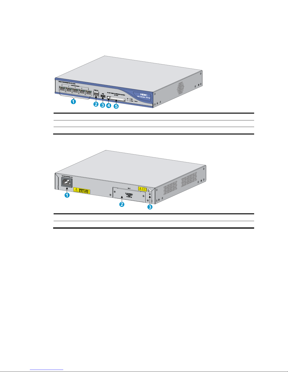
Figure 1 U200-A front view
(1) Copper Ethernet ports (GE0 to GE5) (2) Console port (CONSOLE)
(3) USB port (4) CF ejector button
(5) CF card slot
Page 11

2
Figure 2 U200-A rear view
(1) Grounding screw and sign (2) Power switch (ON/OFF)
(3) AC-input power receptacle (4) Interface module slot 1 (SLOT1)
(5) Interface module slot 2 (SLOT2)
U200-M
Figure 3 U200-M front view
(1) Copper Ethernet ports (GE0 to GE5) (2) Console port (CONSOLE)
(3) USB port (4) CF ejector button
(5) CF card slot
Figure 4 U200-M rear view
(1) Grounding screw and sign (2) Power switch (ON/OFF)
(3) AC-input power receptacle (4) Interface module slot 1 (SLOT1)
3
4
5
1
2
Page 12
3
U200-S
Figure 5 U200-S front view
(1) Copper Ethernet ports (GE0 to GE4) (2) Console port (CONSOLE)
(3) USB port (4) CF ejector button
(5) CF card slot
Figure 6 U200-S rear view
(1) AC-input power receptacle (2) Interface module slot (SLOT)
(3) Grounding screw and sign
Interface modules
Interface modules must be purchased separately.
2GE
The 2GE interface module provides two 10/100/1000BASE-T ports (RJ-45 connectors), which can be
set to operate as Layer 3 interfaces or Layer 2 interfaces.
Page 13

4
Figure 7 2GE interface module panel view
(1) Captive screw
(2) Copper Ethernet port (GE0)
(3) Copper Ethernet port (GE1)
NSQ1GT2UA0
The NSQ1GT2UA0 interface module provides two 10/100/1000BASE-T ports (RJ-45 connectors),
which can be set to operate as Layer 3 interfaces or Layer 2 interfaces.
Figure 8 NSQ1GT2UA0 panel view
(1) Captive screw
(2) Copper Ethernet port (GE0)
(3) Copper Ethernet port (GE1)
NSQ1GP4U0
The NSQ1GP4U0 interface module provides four 1000BASE-X SFP ports, which can be set to operate
as Layer 3 interfaces or Layer 2 interfaces.
Figure 9 NSQ1GP4U0 panel view
(1) Captive screw
(2) Fiber Ethernet SFP ports (SFP0 to SFP3)
1 2 3
Page 14

5
Interface module and UTM device compatibility
matrix
Interface module
U200-A
U200-M
U200-S
2GE × ×
NSQ1GT2UA0 ×
NSQ1GP4U0 ×
Page 15

6
Preparing for installation
Safety recommendations
To avoid possible bodily injury and equipment damage, read all safety recommendations carefully
before installation. Note that the recommendations do not cover every possible hazardous condition.
Safety symbols
When reading this document, note the following symbols:
WARNING means an alert that calls attention to important information that if not understood or
followed can result in personal injury.
CAUTION means an alert that calls attention to important information that if not understood or
followed can result in data loss, data corruption, or damage to hardware or software.
Electricity safety
• Locate the emergency power-off switch in the room before installation. Shut the power off at once
in case accident occurs.
• Make sure the UTM device has been correctly grounded.
• Use an uninterrupted power supply (UPS).
• Do not work alone when the UTM device has power.
• Always check that the power is off.
Laser safety
The UTM device is a Class 1 laser product.
W
ARNING!
• Do not stare into any fiber port when the UTM device has power. The laser light emitted from the
optical fiber may hurt your eyes.
• Use a fiber test equipment, rather than a microscope or magnifier to observe an operating fiber
connector or port when you test link connectivity or system parameters.
Handling safety
When you move the UTM device, follow these guidelines:
• Remove all external cables, including the power cords, before moving the chassis.
• Lift and put down the chassis slowly and never move suddenly.
• When you move multiple UTM devices, use a pallet jack.
Page 16

7
• If the UTM device needs to be moved over a long distance, remove all field-replaceable units
(FRUs), such as interface modules, and package them separately, and install the filler panels
supplied with UTM device.
• If the UTM device needs to be moved over a short distance, make sure all FRUs are securely seated
in slot and the screws are fastened.
• Make sure the accessories of the UTM device are not lost or damaged during UTM device moving.
• Make sure the ground is dry and flat and anti-slip measures are in place.
• Keep the chassis and installation tools away from walk areas.
• Only trained and qualified personnel are allowed to install or service the UTM device.
Examining the installation site
The UTM devices must be used indoors. To ensure normal operation and long service life of your UTM
device, the installation site must meet the requirements in this section.
Weight support
Make sure the floor can support the total weight of the rack, chassis, cards, and all other components.
For more information, see "Dimensions and weight."
Temperature and humidity
Maintain appropriate temperature and humidity in the equipment room.
• Lasting high relative humidity can cause poor insulation, electricity creepage, mechanical property
change of materials, and metal corrosion.
• Lasting low relative humidity can cause washer contraction and ESD and bring problems including
loose captive screws and circuit failure.
• High temperature can accelerate the aging of insulation materials and significantly lower the
reliability and lifespan of the UTM device.
For the temperature and humidity requirements of the UTM device, see Table 2.
Table 2 Temperature r
equirements
Item Tem
p
erature
Operating temperature 0°C to 45°C (32°F to 113°F)
Storage temperature –40°C to +70°C (–40°F to +158°F)
Table 3 Humidity requirements
Item Relative humidit
y
Operating humidity 10% to 95%, noncondensing
Storage humidity 5% to 95%, noncondensing
Page 17
8
Cleanness
Dust buildup on the chassis may result in electrostatic adsorption, which causes poor contact of metal
components and contact points, especially when indoor relative humidity is low. In the worst case,
electrostatic adsorption can cause communication failure.
Table 4 Dust concentration limit in the equipment room
Substance Concentration limit (
p
articles/cu m)
Dust particles
3 x 10⁴
(No visible dust on desk in three days)
NOTE:
Dust particle diameter 5 m
The equipment room must also meet strict limits on salts, acids, and sulfides to eliminate corrosion and
premature aging of components, as shown in Table 5.
Table 5 Harmful gas li
mits in an equipment room
Gas Max. (m
g
/m3)
SO2 0.2
H2S 0.006
NH
3
0.05
Cl
2
0.01
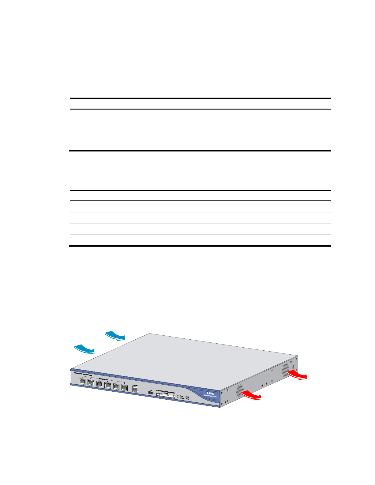
Cooling
The UTM device adopts left to right airflow for heat dissipation. Plan the installation site for adequate
ventilation.
• Leave at least 10 cm (3.94 in) of clearance at the inlet and outlet air vents.
• The installation site has a good cooling system.
Figure 10 Airflow through the chassis (U200-A)
Page 18

9
ESD prevention
CAUTION:
• Check the resistance of the ESD-preventive wrist strap for safety. The resistance readin
g
should be in
the range of 1 to 10 megohm (Mohm) between human body and the ground.
• The UTM device does not provide any ESD-preventive wrist strap. Prepare it yourself.
To prevent electrostatic discharge (ESD), follow these guidelines:
• Make sure the UTM device and rack are properly grounded.
• An anti-static floor is installed and properly grounded.
• Maintain the humidity and temperature at a proper level in the equipment room. For more
information, see "Temperature and humidity."
• Always wear an ESD-preventive wrist strap and ESD-preventive cloth when touching an interface
module or transceiver module.
• Place the removed CF card or interface module on an antistatic workbench, with the face upward,
or put it into an antistatic bag.
• Touch only the edges, instead of electronic components when observing or moving a removed CF
card or interface module.
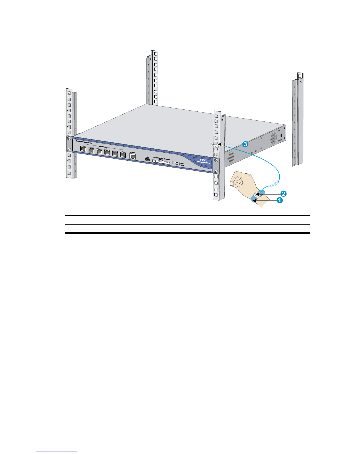
Make sure the rack is properly grounded before you wear an ESD-preventive wrist strap.
To use the ESD-preventive wrist strap:
1. Wear the wrist strap on your wrist.
2. Lock the wrist strap tight around your wrist to keep good contact with the skin.
3. Insert the ESD-preventive plug into the ESD-preventive socket in the chassis.
4. Attach the alligator to the chassis.
Page 19
10
Figure 11 Using an ESD-preventive wrist strap
(1) ESD-preventive wrist strap (2) Lock
(3) Alligator clip
EMI
All electromagnetic interference (EMI) sources, from outside or inside of the UTM device and
application system, adversely affect the UTM device in a conduction pattern of capacitance coupling,
inductance coupling, electromagnetic wave radiation, or common impedance (including grounding
system) coupling. To prevent EMI, perform the following steps:
• Take measures against interference from the power grid.
• Do not use the UTM device together with the grounding equipment or lightning-prevention
equipment of power equipment, and keep the UTM device far away from them.
• Keep the UTM device far away from high-power radio launchers, radars, and equipment with high
frequency or high current.
• Use electromagnetic shielding when necessary.
Lightning protection
To protect the UTM device from lightning, do as follows:
• Make sure the chassis is properly grounded. For how to ground the UTM device, see "Grounding
the UTM de
vice."
• Make sure the grounding terminal of the AC power receptacle is properly grounded.
Page 20
11
• Install a lightning protector at the input end of the power supply to enhance lightning protection
capability. For how to install a lightning protector, see "Connecting the AC power supply to a
power strip with lightning protection."
Rack installation
• Reserve at least 1 m (3.28 ft) of clearance between the rack and walls or other UTM devices.
• Reserve at least 10 cm (3.94 in) of clearance at the air inlet and exhaust vents for ventilation.
• The equipment room is at least 3 m (9.84 ft) high and an air conditioner is installed.
Power supply
Make sure the power source of the installation site is steady and can satisfy the input requirements of
the power modules and parameters such as rated voltage. For power module specifications, see "Power
input."
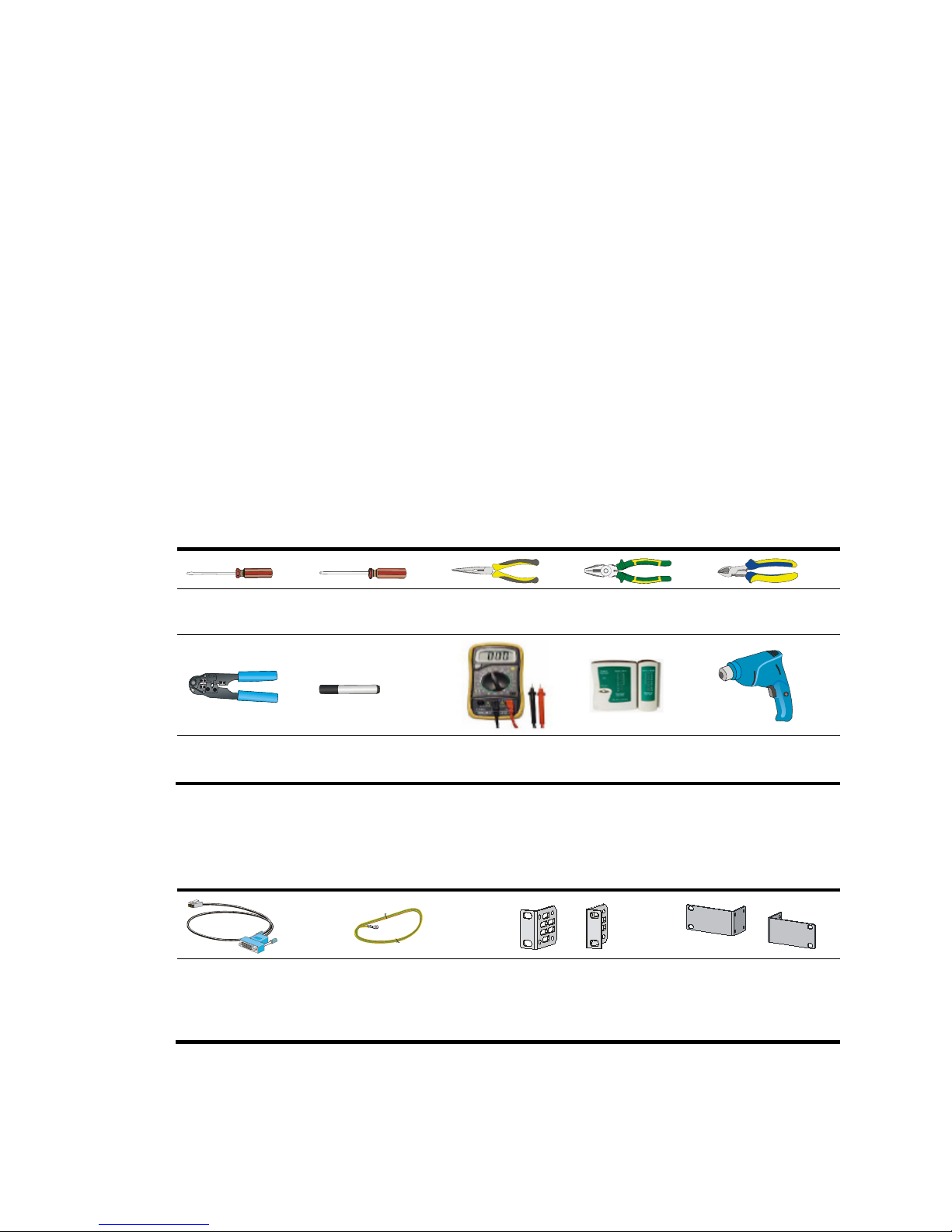
Installation tools
The tools in the table may be used for installing the UTM device. Prepare them yourself.
Flat-blade
screwdriver
Phillips screwdriver Needle-nose pliers
Wire-stripping
pliers
Diagonal pliers
RJ-45 crimping
pliers
Marker Multimeter
Network cable
tester
Hot air blowing
gun
Accessories
Console cable (supplied
with UTM device)
Grounding cable
(supplied with UTM
device)
U200-A and U200-M
front mounting brackets
(supplied with UTM
device)
U200-S mounting
brackets (supplied with
UTM device)
Page 21
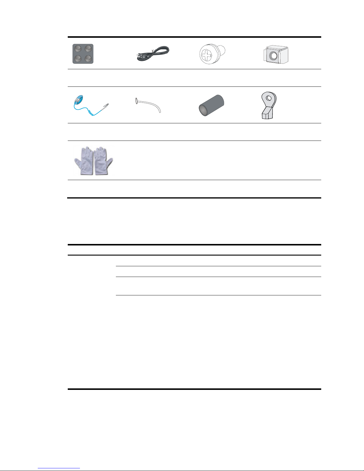
12
Rubber feet (supplied
with UTM device)
AC power cord (supplied
with UTM device)
M6 screw (user-supplied) Cage nuts (user-supplied)
ESD-preventive wrist
strap (user-supplied)
Cable tie (user-supplied)
Insulation sheath
(user-supplied)
Ring terminal
(user-supplied)
ESD-preventive gloves
(user-supplied)
Checklist before installation
Table 6 Checklist before installation
Item Re
q
uirements
Result
Installation site
Temperature 0°C to 45°C (32°F to 113°F)
Relative humidity 10% to 95% (noncondensing)
Cleanness
• Dust concentration ≤ 3 × 10
4
particles/m3
• No dust on desk within three days
ESD prevention
• The equipment and floor are well grounded.
• The equipment room is dust-proof.
• The humidity and temperature are at a proper
level.
• Wear an ESD-preventive wrist strap and uniform
when touching a circuit board.
• Place the removed interface module or CF card
on an antistatic workbench, with the face
upward, or put it into an antistatic bag.
• Touch only the edges, instead of electronic
components when observing or moving a
removed interface module or CF card.
Page 22

13
Item Requirements
Result
EMI prevention
• Take effective measures to protect the power
system from the power grid system.
• Separate the protection ground of the UTM
device from the grounding UTM device or
lightning protection grounding UTM device as far
as possible.
• Keep the UTM device far away from radio
stations, radar and high-frequency UTM devices
working in high current.
• Use electromagnetic shielding when necessary.
Lightning
protection
• The grounding cable of the chassis is well
grounded.
• The grounding terminal of the AC power
receptacle is well grounded.
• A port lightning arrester is installed. (Optional)
• A power lightning arrester is installed. (Optional)
Electricity safety
• Equip an uninterrupted power supply (UPS).
• In case of emergency during operation, switch off
the external power switch.
Space
• Reserve at least 10 cm (3.94 in) of clearance at
the air inlet and exhaust vents for ventilation.
• The rack or workbench has a good ventilation
system.
Workbench The workbench is sturdy and well grounded.
Rack-mounting
requirements
• Install the UTM device in an open rack if possible.
If you install the UTM device in a closed cabinet,
make sure the cabinet is equipped with a good
ventilation system.
• The rack is sturdy enough to support the weight of
the UTM device and installation accessories.
• The size of the rack is appropriate for the UTM
device.
• The front and rear of the rack are at least 0.8 m
(2.62 ft) away from walls or other UTM devices.
Safety
recommendations
• Do not place the switch near water or in a damp environment.
Prevent water or moisture from entering the switch chassis.
• Locate the emergency power-off switch in the room before
installation. Shut the power off at once in case accident occurs.
Tools
• Installation accessories supplied with the UTM device
• User supplied tools
Reference
• Documents shipped with the UTM device
• Online documents
Page 23
14
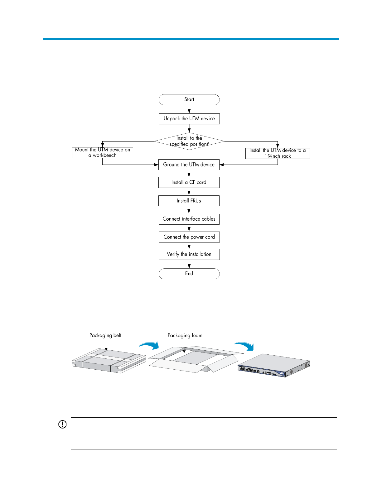
Installing the UTM device
Figure 12 UTM device installation flow
Unpacking the UTM device
Figure 13 Unpacking the UTM device
Mounting the UTM device on a workbench
IMPORTANT:
• Ensure good ventilation and 10 cm (3.94 in) of clearance around the chassis for heat dissipation.
• Avoid placing heavy objects on the UTM device.
Page 24
15
To mount the UTM device on a workbench:
1. Verify that the workbench is sturdy and well grounded.
2. Place the UTM device with bottom up, and clean the round holes in the chassis bottom with dry
cloth.
3. Attach the rubber feet to the four round holes in the chassis bottom.
4. Place the UTM device with upside up on the workbench.
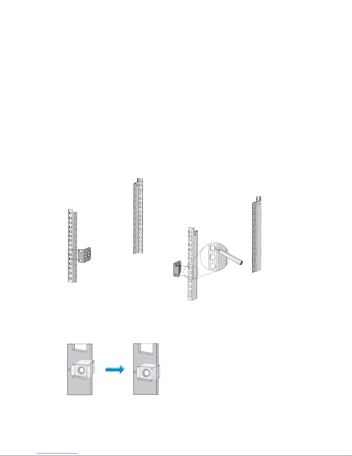
Installing the UTM device in a 19-inch rack
The installation procedures for the U200 series UTM devices are similar. This section uses a U200-A as
an example.
To install the UTM device in the rack:
1. As shown in Figure 14, mar
k the positions of the cage nuts on the front rack posts by using a front
mounting bracket.
Figure 14 Marking the positions of the cage nuts
2. As shown in Figure 15, insert one edge of a cage nut into the hole, and compress the other edge
of the cage nut to push the cage nut fully into the hole.
Figure 15 Installing cage nuts
Page 25
16
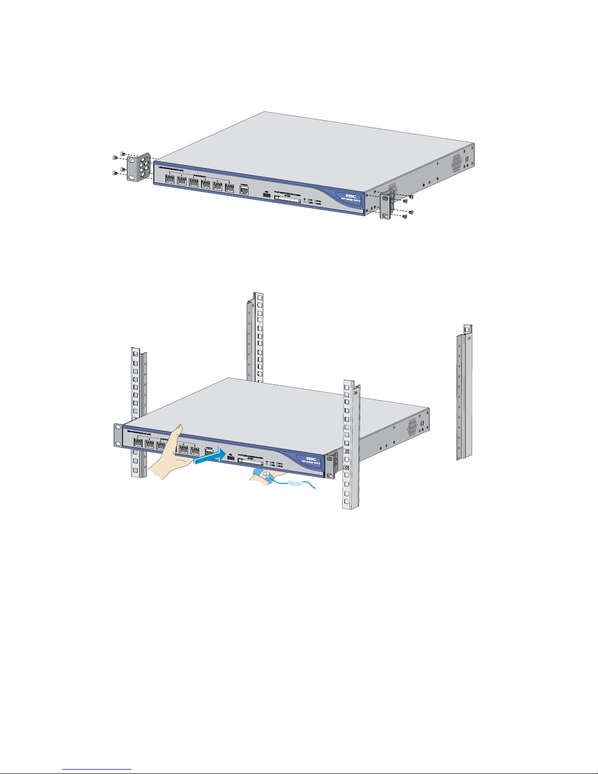
3. Use the screws supplied with the UTM device to attach the mounting brackets to the UTM device,
as shown in Figure 16.
Figure 16 Attaching th
e mounting brackets
4. Supporting the bottom of the UTM device with one hand, hold the UTM device with the other
hand, and slide the UTM device into the rack.
Figure 17 Sliding the UTM device into the rack
5. Attach the UTM device horizontally by fastening the mounting brackets to the rack with M6
screws.
Page 26

17
Figure 18 Mounting the UTM device to the rack
Grounding the UTM device
W
ARNING!
Correctly connecting the UTM device grounding cable is crucial to lightning protection and EMI
protection.
The power input end of the UTM device has a noise filter, whose central ground is directly connected to
the chassis to form the chassis ground (commonly known as PGND). You must securely connect this
chassis ground to the earth so the faradism and leakage electricity can be safely released to the earth to
minimize EMI susceptibility of the UTM device.
Attaching the ring terminal
1. Cut the grounding cable as appropriate for connecting to the grounding strip.
2. Peel 5 mm (0.20 in) of insulation sheath by using a wire stripper, and insert the bare metal part
through the black insulation covering into the end of the ring terminal.
3. Secure the metal part of the cable to the ring terminal with a crimper.
4. Cover the joint with the insulation covering, and heat the insulation covering with a blow dryer to
completely cover the metal part.
Page 27

18
Figure 19 Attaching the ring terminal
Connecting the grounding cable
1. Remove the grounding screw from the rear panel of the UTM device chassis.
2. Attach the grounding screw to the ring terminal of the grounding cable.
3. Use a Phillips screwdriver to fasten the grounding screw into the grounding screw hole.
4. Connect the other end of the grounding cable to the grounding strip of the rack.
Figure 20 Connecting the grounding cable to the grounding hole of UTM device
NOTE:
• The resistance reading should be smaller than 5 ohms between UTM device chassis and the ground.
• To guarantee the grounding effect, use the grounding cable provided with the UTM device to connec
t
to the grounding strip in the equipment room as long as possible.
Page 28

19
Installing a CF card
1. Push the CF card eject button all the way into the slot and make sure the button does not project
from the panel.
2. Insert the CF card into the slot following the direction shown in Figure 21, and
make sure it does
not project from the slot.
Figure 21 Inserting the CF card into the slot
Connecting interface cables
Connecting a copper Ethernet port
1. Plug one end of a twisted pair cable into the port.
2. Plug the other end of the twisted pair cable into the RJ-45 Ethernet port of the peer device.
3. Examine the port LED status.
For more information about the LED status, see "UTM device panel LEDs."
A
fter you connect the UTM device to the network, execute the ping or tracert command to test network
connectivity. For more information about the commands, see the command reference of the UTM device.
For more information about Ethernet twisted pair cables, see "Ethernet twisted pair cable."
Connecting a fiber port
W
ARNING!
Do not stare into any fiber port when you connect an optical fiber. The laser li
g
ht emitted from the optical
fiber may hurt your eyes.
CAUTION:
• Be sure to install the dust cover if the fiber port is not connected to a fiber connector.
• Never bend or curve a fiber when connecting it. The bend radius must be at least 10 cm (3.94 in).
• Keep the end of the fiber clean.
• Make sure the Tx and Rx ends of the SFP transceiver module are properly connected.
The UTM device has SFP and XFP fiber ports, which only support LC connectors.
Page 29

20
To connect a fiber port to a peer device through optical fibers:
1. Remove the dust plug from the SFP port.
2. Remove the dust cover from the transceiver module, and plug the end without a pull latch into the
SFP port.
3. Remove the dust cover from the fiber connector.
4. Identify the Rx and Tx ports. Plug the LC connector at one end of one fiber cable into the Rx port
of the UTM device and the LC connector at the other end into the Tx port of the peer device. Plug
the LC connector at one end of another fiber cable into the Tx port of the UTM device and the LC
connector at the other end to the Rx port of the peer device.
Figure 22 Connecting the fiber port
5. View the LINK LED after connection:
{ On means a link is present.
{ Off means no line is present. Try to change the Rx and Tx ends of the fiber. For more
information about the LEDs, see "UTM device panel LEDs."
Connecting a power cord
1. Make sure the UTM device is properly grounded. For the U200-A and U200-M, make sure the
power is OFF.
2. Connect one end of the power cord to the receptacle on the UTM device, and the other end to the
AC power source.
Page 30

21
Figure 23 Connecting a power cord to the UTM device
Verifying the installation
To ensure normal operation of the UTM device, verify the following items before you power on the UTM
device:
• There is enough space for heat dissipation around the UTM device.
• The grounding cable is securely connected.
• The correct power source is used.
Page 31

22
Installing FRUs
You can install a Mini/MIM interface module, a lightning protector for a network port, and AC power
supply lightning protector on a UTM device. These components do not come with the UTM device.
Prepare them yourself.
Installing a Mini interface module
1. Loosen the screws on the filler panel with a Phillips screwdriver to remove the filler panel.
Put the removed filler panel and screws in an antistatic bag for future use.
2. Push the Mini interface module with its components facing upwards along the guide rails into the
slot.
Figure 24 Pushing the interface module into the slot
3. Fasten the captive screws on the interface module with a Phillips screwdriver.
Installing a MIM interface module
1. Loosen the captive screws on the filler panel with a Phillips screwdriver to remove the filler panel.
Put the removed filler panel and screws in an antistatic bag for future use.
2. Push the MIM interface module with its components facing upwards along the guide rails into the
slot.
Figure 25 Pushing the MIM interface module into the slot
3. Fasten the captive screws on the interface module with a Phillips screwdriver.
Page 32

23
Installing a lightning protector for a network port
Installation procedure
IMPORTANT:
Read the instructions for the lightning protector carefully before you install it.
To install a lightning protector:
1. Use a double-faced adhesive tape to stick the lightning protector onto the UTM device chassis,
and make sure it is close to the grounding screw of the UTM device as possible.
2. Measure the distance between the protector and the grounding screw of the UTM device, cut the
ground wire of the protector as appropriate, and securely tighten the ground wire to the
grounding screw of the UTM device.
3. Use the multimeter to measure whether the ground wire of the protector contacts well with the
grounding screw of chassis.
4. Insert the outdoor network cable into the protector's IN end, and the cable connected to the UTM
device into the OUT end, and check the indicators on the lightning protector to verify that the
connection is correct.
5. Use nylon ties to bundle the cables neatly.
Figure 26 Installing a lightning protector
(1) Lightning protector for a network port
(2) Grounding wire
Installation precautions
The performance of the port lightning protector may be affected in the following cases:
• The port lightning protector is installed in reverse direction. Connect the IN end to the outdoor
network cable and the OUT end to the network port on the UTM device.
• The port lightning protector is not well grounded. After the connection, use the multimeter to
confirm that the ground wire for the protector is as short as possible to ensure its good contact with
the grounding screw of the UTM device.
• The installed port lighting protectors are not sufficient. If the UTM device has more than one
network port connected with other devices through cables outdoor, install a lightning protector for
each network port.
Page 33

24
Connecting the AC power supply to a power strip
with lightning protection
CAUTION:
Make sure the PE terminal of the power socket has been securely grounded.
If part of the AC power line is routed outdoors, use a power strip with lightning protection to connect the
AC power cord of the UTM device to the AC power line to protect the UTM device from being damaged
by lightning strikes.
You can attach the power strip to the rack, workbench, or wall of equipment room.
After you connect the AC power cord from the UTM device to a socket on the power strip, verify that the
green RUN LED on the strip is on and the red LED is off.
If the red LED is on, use a multimeter to check the polarity of the wires in the power socket for wrong
connections. If the zero wire (left) and the live wire (right) are correctly connected, check for missing
grounding connection.
Figure 27 Power strip with lightning protection
(1) Operating LED (green) On means the circuit is operating properly.
Off means the circuit is damaged.
(2) Grounding/pole detection
LED (red)
On indicates a wrong wire connection (the wire is not grounded or the
live line and null line are reversely connected), and you need to check the
power supply line.
(3) Power switch
(4) IEC standard socket It is used to connect to the power supply in the equipment room through a
power cord.
(5) Overload automatic protector The protector automatically opens the electric circuit when the current
exceeds the threshold and closes the electric circuit when the current
drops below the threshold.
(6) Multifunctional socket It is used to connect the power supply of the UTM device.
N
NNN
L
LL
L
Page 34

25
Logging in and performing basic
configurations
The first time you access the UTM device, you can log in to the CLI through the console port or log in to
the Web interface by using a Web browser. After login, you can configure Telnet for remote access.
Logging in to the CLI through the console port
To log in to the CLI through the console port, you must have a console cable and a terminal (for example,
a PC).
The terminal can be any character terminal with an RS-232 port or a PC. Typically, a PC running a
terminal emulation program (such as HyperTerminal on a Windows operating system) is used. In the
following sections, a PC running Windows XP HyperTerminal is used.
The console cable can be an 8-core shielded cable that has an RJ-45 connector at one end for
connecting to the console port of the UTM device and a DB-9 female connector at the other end for
connecting to the serial port on the terminal.
Connecting the terminal to the UTM device
1. Plug the DB-9 female connector of the console cable to the serial port of the PC.
2. Plug the RJ-45 connector of the console cable to the console port of the UTM device.
Figure 28 Connecting the terminal to the UTM device
IMPORTANT:
• Identify the mark on the console port and make sure you are connecting to the correct port.
• The serial ports on PCs do not support hot swapping. If the UTM device has been powered on, always
connect the console cable to the PC before connecting it to the UTM device, and when you disconnec
t
the cable, first disconnect it from the UTM device.
Page 35

26
Configuring communication parameters on the terminal
1. On the PC, select Start > Programs > Accessories > Communications > HyperTerminal.
2. Enter a name for the connection and click OK.
Figure 29 Creating a HyperTerminal connection
3. Select the serial port used to connect to the UTM device and click OK.
Figure 30 Selecting the serial port
4. Configure serial port properties as described in Table 7.
Page 36

27
Figure 31 Configuring serial port properties
Table 7 Serial port properties
Pro
p
erty Value
Bits per second 9600 bps (the default)
Data bits 8
Parity None
Stop bits 1
Flow control None
To restore the default settings, click Restore Defaults.
5. Click OK.
The HyperTerminal window appears.
Page 37

28
Figure 32 HyperTerminal window
6. Select File > Properties and then click the Settings tab.
Figure 33 Selecting the emulation type
Page 38

29
7. Select VT100 or Auto detect for Emulation and click OK.
Powering on the UTM device
Before powering on the UTM device, confirm the following:
• You know where the emergency power-off switch for the equipment room is located.
• The power cables and grounding cables have been correctly connected.
• The input power voltage meets the requirement of the UTM device.
• The terminal is properly connected to the UTM device and operating normally, and the
communication parameters have been configured as required.
• The CF card used to store the applications, if any, is tightly fixed in the UTM device.
• The interface modules, if any, are properly installed, and the interface cables are correctly
connected.
To power on the U200-S device, turn on the power source.
To power on the U200-A or U200-M device, turn on the power source and then turn on the power
switch of the device.
After powering on the device, verify the following items:
1. The LEDs on the front panel show that the device is operating properly. For more information
about the LED behaviors, see "UTM device panel LEDs."
2. The cooling system is working, and you can hear fan rotating noise and feel air being blown out.
3. The boot information on the terminal shows that the UTM device is starting up normally. For more
information, see "Verifying the UTM device boot information."
4. After the devic
e starts up, a prompt for pressing Enter appears.
Verifying the UTM device boot information
After the UTM device is powered on, the following information appears on the terminal:
System is starting...
Press Ctrl+D to access BASIC-BOOTWARE MENU
Booting Normal Extend BootWare..
The Extend BootWare is self-decompressing....................
Done!
****************************************************************************
* *
* H3C SecPath U200-S BootWare, Version 1.36 *
* *
****************************************************************************
Copyright (c) 2004-2013 Hangzhou H3C Technologies Co., Ltd.
Compiled Date : Apr 9 2013
CPU Type : XLS404
CPU L1 Cache : 32KB
CPU Clock Speed : 800MHz
Memory Type : DDR2 SDRAM
Page 39

30
Memory Size : 512MB
Memory Speed : 533MHz
BootWare Size : 512KB
Flash Size : 32MB
cfa0 Size : 224MB
CPLD Version : 2.0
PCB Version : Ver.B
BootWare Validating...
Press Ctrl+B to enter extended boot menu...
Starting to get the main application file--cfa0:/u200s.bin!.................
............................................................................
............................................................................
............................................................................
..................................
The main application file is self-decompressing.............................
............................................................................
..........................................................................
Done!
System application is starting...
Press Ctrl+F to load firewall system...
##### start UTM mode #####
User interface con0 is available.
Press ENTER to get started.
After pressing Enter, you are placed in user view:
<H3C>
Now, you can configure and manage the UTM device.
Logging in to the CLI by using Telnet
This section provides only a simplified procedure for logging in to the CLI by using Telnet. For more
information, see the UTM device configuration guides.
The UTM device does not support Telnet login by default, but is provided with the following default
Telnet login information:
• Username—admin.
• Password—admin.
• IP address for interface GigabitEthernet 0/0— 1 9 2 .16 8 . 0 .1 / 2 4 .
To log in to the CLI by using Telnet:
1. Log in to the UTM device through the console port, execute the telnet server enable command in
system view to enable the Telnet service.
Page 40

31
2. Connect a PC to the UTM device's interface GigabitEthernet 0/0 by using a crossover Ethernet
cable.
3. Assign the PC an IP address in the network segment 192.168.0.0/24 (except for 192.168.0.1),
for example, 192.168.0.2.
4. Run the Telnet client on the PC to Telnet to the UTM device.
Logging in to the Web interface
The UTM device supports Web login by default, and is provided with the following default Web login
information:
• Username—admin.
• Password—admin.
• IP address for interface GigabitEthernet 0/0— 1 9 2 .16 8 . 0 .1 / 2 4 .
To log in to the Web interface:
1. Connect a PC to the UTM device's interface GigabitEthernet 0/0 by using a crossover Ethernet
cable.
2. Assign the PC an IP address in the network segment 192.168.0.0/24 (except for 192.168.0.1),
for example, 192.168.0.2.
3. Launch a Web browser on the PC and enter 192.168.0.1 in the address bar.
The Web login page appears.
Figure 34 Web login page
4. Enter the correct username, password, and verify code, select English as the language, and click
Login.
NOTE:
A
user uses the default accont admin to log in to the Web network management page for the first time.To
ensure the system security, the user must create a new administrator account and delete the default user
account after logging in.For information about how to create a new administrator account and delete the
default user account, see
H3C SecPath Series Firewalls and UTM Devices Getting Started Guide.
Page 41

32
Performing basic configurations
To enable the UTM device to communicate with other devices on the network, you must perform some
basic configurations on the UTM device. To do so, first log in to the CLI or Web interface of the UTM
device.
To use an interface as a service interface, you must add it to a non-management security zone in the
Web interface before configuring relevant service functions. For more information, see the UTM device
configuration guides.
This section describes the steps for performing basic configurations on the UTM device. For how to
configure protocols and features on the UTM device, see the UTM device configuration guides.
The syntax of commands and the Web interface vary with software versions.
Performing basic configurations at the CLI
Step Command
Remarks
1. Enter system view.
system-view N/A
2. Set the device name.
sysname sysname
Optional.
H3C by default.
3. Enable the Telnet server.
telnet server enable
Optional.
Disabled by default.
4. Configure a one-to-one static
NAT mapping.
nat static local-ip [ vpn-instance
local-name ] global-ip
Optional.
By default, no static NAT mapping
is configured.
5. Enter Ethernet interface view.
interface interface-type
interface-number
N/A
6. Assign an IP address to the
interface.
ip address ip-address
{ mask-length | mask } [ sub ]
Optional.
By default, only GigabitEthernet
0/0 has an IP address
(192.168.0.1).
7. Enable static NAT on the
interface.
nat outbound static [ track vrrp
virtual-router-id ]
N/A
8. Add the interface to a security
zone.
See the UTM device
configuration guides.
This task is not supported at the
CLI. Complete this task in the Web
interface.
9. Return to the upper-level view.
quit N/A
10. Save the running configuration
to the root directory of the
storage medium and specify
the file as the configuration file
for the next startup.
save [ safely ] N/A
11. Display the running
configuration.
display current-configuration Optional.
Page 42

33
Performing basic configurations in the Web interface
This section describes the procedure for performing basic configuration in the Web interface.
Launching the basic configuration wizard
1. In the Web interface, select Wizard from the navigation tree.
2. Click the Basic Device Information link to enter the first basic configuration page.
Figure 35 Basic configuration wizard—1/6
Configuring the system name and user password
1. Click Next on the first basic configuration page to enter the username and password
configuration page.
Page 43

34
Figure 36 Basic configuration wizard—2/6 (username and password configuration)
2. Configure the system name and user password as described in Table 8.
Table 8 Configuration items
Item Descri
p
tion
Sysname Set the system name. The default system name is H3C.
Modify Current User
Password
Specify whether to change the login password.
To change the password, enter the new password and confirm it.
The default username and password are both admin.
New Password
Confirm Password
Password Encryption
Set the password encryption mode:
• Reversible—The firewall encrypts the user password with a reversible algorithm
and saves the password.
• Irreversible—The firewall encrypts the user password with an irreversible
algorithm and saves the password.
Configuring services
1. Click Next on the username and password configuration page to enter the service management
page.
Page 44

35
Figure 37 Basic configuration wizard—3/6 (service management)
2. Configure services as described in Table 9.
Table 9 Configuration items
Item Descri
p
tion
FTP
Specify whether to enable the FTP service on the UTM device.
By default, the FTP service is disabled.
Telnet
Specify whether to enable the Telnet service on the UTM device.
By default, the Telnet service is disabled.
HTTP
Specify whether to enable the HTTP service on the UTM device.
To enable the HTTP service on the UTM device, select the Enable option and select
the HTTP service port number.
By default, the HTTP service is enabled.
IMPORTANT:
• If you are using the HTTP service, disabling the HTTP service or changing the
service port number breaks your connection to the UTM device.
• Make sure no other services are using the specified service port number.
Page 45

36
Item Description
HTTPS
Specify whether to enable the HTTPS service on the UTM device.
To enable the HTTPS service on the UTM device, select the Enable option and select
the HTTPS service port number.
By default, the HTTP service is disabled.
To improve the security of your connection to the UTM device, use HTTPS, which is
based on SSL.
IMPORTANT:
• If you are using the HTTPS service, disabling the HTTPS service or changing the
service port number breaks your connection to the UTM device.
• Make sure no other services are using the specified service port number.
• HTTPS uses the PKI domain default by default. If the PKI domain does not exist,
you will see an error message at the end of the wizard. However, the other
configurations are not affected.
Configuring IP addresses for interfaces
1. Click Next on the service management page to enter the interface IP address configuration page.
The list shows the IP address configuration information for all Layer 3 Ethernet interfaces and
VLAN interfaces.
Figure 38 Basic configuration wizard—4/6 (interface IP address configuration)
2. Click the link for an interface to perform IP address configuration as described in Table 10.
Page 46

37
Table 10 Configuration items
Item Descri
p
tion
IP Configuration
Select an IP address acquisition approach for the
interface:
• None—Assigns no IP address to the interface.
• Static Address—If you select this option, you must
manually assign an IP address and a mask to the
interface.
• DHCP—Enables the interface to automatically obtain
an IP address through the DHCP protocol.
• Do not change—Leaves the IP address of the interface
unchanged.
IMPORTANT:
Changing the IP
address of the interface
you are using
disconnects you from
the UTM device.
IP Address Configure an IP address and a mask for the interface.
These two fields are available only when the value of the IP
Configuration field is Static Address.
Mask
Configuring NAT
1. Click Next on the interface IP address configuration page to enter the NAT configuration page.
Figure 39 Basic configuration wizard—5/6 (NAT configuration)
2. Complete NAT configuration as described in Table 11.
Table 11 Configuration items
Item Descri
p
tion
Interface
Select the interface to which the NAT configuration will be applied, typically the
outbound interface of the UTM device.
Page 47

38
Item Description
Dynamic NAT
Specify whether to enable dynamic NAT on the interface.
If dynamic NAT is enabled, the IP address of the interface will be used as the IP
address of a matched packet after the translation.
By default, dynamic NAT is disabled.
Source IP/Wildcard
Specify the source IP address and wildcard for matching packets.
These fields are available only when dynamic NAT is enabled.
Destination
IP/Wildcard
Specify the destination IP address and wildcard for matching packets.
These fields are available only when dynamic NAT is enabled.
Protocol Type
Specify the protocol type for matching packets. Valid values include TCP, UDP, and
IP (IP indicates any protocol carried by the IP protocol).
This field is available only when dynamic NAT is enabled.
Internal Server
Specify whether to enable the internal server.
If the internal server is enabled, when an external user accesses the internal server,
the NAT function translates the destination address of the request packets into the
private IP address of the internal server. Accordingly, when the internal server
replies, the NAT function translates the source address (private IP address) of reply
packets into the public IP address.
By default, the internal server is disabled.
IMPORTANT:
Configuring the internal server might break your connection to the UTM device. For
example, if you specify the IP address of your local host or the IP address of your access
interface as the external IP address, your connection will be broken.
External IP: Port
Specify the IP address and service port number for external user access.
These fields are available only when the internal server is enabled.
Internal IP: Port
Configure the IP address and service port number of the internal server.
These fields are available only when the internal server is enabled.
Completing the configuration wizard
1. Click Next on the NAT configuration page.
All configurations you have made in the basic configuration wizard are displayed.
Page 48

39
Figure 40 Basic configuration wizard—6/6
2. To modify your configuration, click Back to go back to the previous page.
3. To save the current configuration to the startup configuration file for the next device boot when
you submit the configurations, select Save Configuration.
4. Click Finish to complete the configuration.
Page 49

40
Replacement procedures
Precautions
• Always wear an ESD-preventive wrist strap or ESD-preventive gloves when servicing the UTM
device.
• No interface modules for the UTM device are hot-swappable. Power off the UTM device before
replacing hardware.
• When removing FRUs (such as Mini or MIM interface modules, and the CF card):
{ Ensure good alignment with the slot and use uniform force to avoid damage to the FRUs.
{ Completely loosen each captive screw before removing Mini or MIM interface modules to
keep their panels in good condition.
{ Hold a PCB by its edges. Do not touch any electronic components.
{ Put the removed FRUs on an antistatic workbench with the PCB side facing upward or place
them in antistatic bags.
Replacing a Mini interface module
1. Loosen the two captive screws with a Phillips screwdriver.
2. Holding the front part of the Mini interface module, gently pull it out along the slide rails.
3. Install a new Mini interface module.
For the installation procedures, see "Installing a Mini interface module."
If no new Min
i interface module is to be installed to the slot, install a filler panel to prevent dust
from entering the chassis.
Figure 41 Pulling out a Mini interface module
Replacing a MIM interface module
1. Loosen the captive screws with a Phillips screwdriver.
Page 50

41
2. Holding the clasp of the MIM interface module, gently pull out the MIM interface module along
the slide rails.
3. Install a new MIM interface module.
For the installation procedures, see "Installing a MIM interface module."
If no new MIM interface module is to be installed to the slot, install a filler panel to prevent dust
from entering the chassis.
Figure 42 Pulling out a MIM interface module
Replacing a CF card
CAUTION:
To avoid hardware damage, do not remove the CF card when the UTM device is booting or the LED is
flashing.
To replace a CF Card:
1. Check whether the CF card LED is flashing. If yes, the system is accessing the CF card. Proceed to
the next step after the LED stops flashing.
2. Press the CF card eject button so that the eject button projects from the panel.
3. Press the eject button again to eject the CF card part-way out of the slot.
4. Pull the CF card out of the slot.
To protect the removed CF card, place it in an antistatic bag.
5. Install a new CF card.
For the installation procedures, see "Installing a CF card."
Figure 43 Removing a CF card
Page 51

42
Replacing a transceiver module
1. Pressing the tab of the LC connector, pull out the LC connector from the transceiver module.
Put on the dust plug for the LC connector.
2. Pivot the clasp of the transceiver module down to the horizontal position.
3. Hold the clasp to pull the transceiver module out of the socket.
4. Put the dust plug on the removed module, and put the removed module into its original shipping
materials.
5. Install a new transceiver module.
For the installation procedures, see "Connecting a fiber port."
Figure 44 Removing a transceiver module
Page 52

43
Hardware management and maintenance
This chapter describes how to display running information for the UTM device, verify and diagnose
transceiver modules, troubleshoot system exceptions, and reboot the UTM device.
NOTE:
The output depends on your software version.
Displaying hardware information
Displaying software and hardware version information
Use the display version command to display software and hardware version information for the UTM
device.
<Sysname> display version
H3C Comware Platform Software
Comware Software, Version 5.20, Release 5140
Copyright (c) 2004-2013 Hangzhou H3C Tech. Co., Ltd. All rights reserved.
H3C SecPath U200-S uptime is 0 week, 0 day, 0 hour, 6 minutes
CPU type: XXX
512M bytes DDR2 SDRAM Memory
32M bytes Flash Memory
247M bytes CF0 Card
PCB Version:Ver.B
Logic Version: 2.0
Basic BootWare Version: 1.36
Extend BootWare Version: 1.36
[FIXED PORT] CON (Hardware)Ver.B, (Driver)1.0, (Cpld)2.0
[FIXED PORT] GE0/0 (Hardware)Ver.B, (Driver)1.0, (Cpld)2.0
[FIXED PORT] GE0/1 (Hardware)Ver.B, (Driver)1.0, (Cpld)2.0
[FIXED PORT] GE0/2 (Hardware)Ver.B, (Driver)1.0, (Cpld)2.0
[FIXED PORT] GE0/3 (Hardware)Ver.B, (Driver)1.0, (Cpld)2.0
[FIXED PORT] GE0/4 (Hardware)Ver.B, (Driver)1.0, (Cpld)2.0
[SUBCARD 1] The SubCard is not present
[SUBCARD 2] The SubCard is not present
Displaying running status data
For diagnosis or troubleshooting, you can use the display diagnostic-information command in any view
to bulk collect running data for multiple modules, rather than using separate display commands (such
as display clock, display version, display device, and display current-configuration) to collect running
status data module by module.
Page 53

44
• Save running status data for multiple feature modules.
<Sysname> display diagnostic-information
Save or display diagnostic information (Y=save, N=display)? [Y/N]:y
Please input the file name(*.diag)[cfa0:/default.diag]:aa.diag
Diagnostic information is outputting to cfa0:/aa.diag.
Please wait...
Save successfully.
To view the content of file aa.diag, execute the more aa.diag command in user view, in
combination of the Page Up and Page Down keys.
• Display running status data for multiple feature modules.
<Sysname> display diagnostic-information
Save or display diagnostic information (Y=save, N=display)? [Y/N]:n
=================================================================
===============running CPU usage information===============
=================================================================
===== Current CPU usage info =====
CPU Usage Stat. Cycle: 9 (Second)
CPU Usage : 3%
CPU Usage Stat. Time : 2013-08-20 11:18:19
CPU Usage Stat. Tick : 0x7(CPU Tick High) 0xe098ecec(CPU Tick Low)
Actual Stat. Cycle : 0x0(CPU Tick High) 0x2422a5b3(CPU Tick Low)
TaskName CPU Runtime(CPU Tick High/CPU Tick Low)
IPCB 0% 0/ 3d160
VIDL 97% 0/233284bf
TICK 0% 0/ 1bbaef
STMR 0% 0/ 19b268
DRVT 0% 0/ ccbf2
TMSG 0% 0/ 1126e8
RPCQ 0% 0/ dd4af
IPCM 0% 0/ 2b5a
INFO 0% 0/ 55b5
OMS 0% 0/ 4d08
DEV 0% 0/ da99
SOCK 0% 0/ 6e37
ADJ4 0% 0/ 6abd
ACL 0% 0/ 3aa2
LAGG 0% 0/ 4f0f
MSTP 0% 0/ 2e8c
ARP 0% 0/ 10835
IP 0% 0/ 206f4
FSLH 0% 0/ 2681
FSLR 0% 0/ 1acca
NTPT 0% 0/ 3329
VTYD 0% 0/ 20f55
DT1X 0% 0/ 372ac
ACM 0% 0/ 1671c
LS 0% 0/ 1d34b
Page 54

45
RDS 0% 0/ 16472
SC 0% 0/ 5771
IKE 0% 0/ bd6b0
L2TP 0% 0/ 1d4e8
MACA 0% 0/ 1c929
PSEC 0% 0/ 5151
ULOG 0% 0/ 1c347
MFIB 0% 0/ 12d5
STND 0% 0/ 9868
ROUT 0% 0/ 19374c
IFNT 0% 0/ 3e65
IPFF 0% 0/ 2e02
co0 0% 0/ 4c7aa2
…
Displaying detailed information about interface modules
Use the display device verbose command to display detailed information about interface modules.
<Sysname> display device verbose
[H3C]display device verbose
Status :OK
Type :RPU
Hardware :B
Driver :1.0
CPLD :2.0
SubCard Num :3
CFCard Num :1
Usb Num :1
The Fixed SubCard0 on Board0
Status :Normal
Type :Fixed Subcard
Hardware :B
Driver :1.0
CPLD :2.0
The SubCard1 on Board0:
Status :Absent
The SubCard2 on Board0:
Status :Absent
Displaying the electrical label data
Electrical label data is also called permanent configuration data or archive information, including name
of the interface module, interface module serial number, MAC address, and vendor name.
• Use the display device manuinfo command to display the electronic label data for interface
modules.
Page 55

46
<Sysname> display device manuinfo
slot 0
DEVICE_NAME:Navigator2-2
DEVICE_SERIAL_NUMBER:210231A91NA08B000004
MAC_ADDRESS:000f-e2ec-2ce0
MANUFACTURING_DATE:2009-1-13
VENDOR_NAME:H3C
• Use the display device manuinfo slot slot-number command to display the electronic label data for
the interface module that is specified by the slot slot-number option.
<Sysname> display device manuinfo slot 0
DEVICE_NAME:Navigator2-2
DEVICE_SERIAL_NUMBER:210231A91NA08B000004
MAC_ADDRESS:000f-e2ec-2ce0
MANUFACTURING_DATE:2009-1-13
VENDOR_NAME:H3C
Table 12 Command output
Field Descri
p
tion
The operation is not
supported on the specified
board or subslot
The method that uses the display device manuinfo command to display the
electronic label data for interface modules is not supported.
Displaying CPU usage statistics
Use the display cpu-usage command to display CPU usage statistics.
<Sysname> display cpu-usage
Unit CPU usage:
1% in last 5 seconds
1% in last 1 minute
1% in last 5 minutes
Table 13 Command output
Field Descri
p
tion
Unit CPU usage CPU usage statistics
1% in last 5 seconds
After a boot, the system calculates and records the average CPU usage rate
every five seconds.
This field displays the average CPU usage rate in the last five seconds.
1% in last 1 minute
After a boot, the system calculates and records the average CPU usage rate
every one minute.
This field displays the average CPU usage rate in the last minute.
1% in last 5 minutes
After a boot, the system calculates and records the average CPU usage rate
every five minutes.
This field displays the average CPU usage rate in the last five minutes.
Page 56

47
Displaying memory usage statistics
Use the display memory command to display memory usage statistics.
<Sysname> display memory
System Total Memory(bytes): 120564400
Total Used Memory(bytes): 57903384
Used Rate: 48%
Table 14 Command output
Field Descri
p
tion
System Total Memory(bytes) Total size of the system memory (in bytes)
Total Used Memory(bytes) Size of the memory used (in bytes)
Used Rate Percentage of the memory used to the total memory
Displaying information about the CF card
Use the display device cf-card command to display information about the CF card.
<Sysname> display device cf-card
Compacted Flash Card Information:
CF ID 0 :
Status: Normal
Size : 247M bytes
Table 15 Command output
Field Descri
p
tion
CF ID Slot number of the CF card
Status
CF card status, which can be:
• Absent—No CF card is in the slot.
• Fault—The CF card has failed.
• Normal—The CF card is operating properly.
Size Storage memory of the CF card
Displaying the operating states of fans
Use the display fan command to display the operating states of fans.
<Sysname> display fan
Fan 1 State: Normal
Table 16 Command output
Field Descri
p
tion
Fan 1 Number of fan
Page 57

48
Field Description
State
Fan status, which can be:
• Normal—The fan is operating properly.
• Absent—The fan is not present.
• Fault—The fan has failed.
Displaying power supply information
Use the display power command to display power supply information.
<Sysname> display power
Power Information:
Power 1 Status: Normal
Table 17 Command output
Field Descri
p
tion
Power 1 Power supply number
Status
Power supply status, which can be:
• Normal—The power supply is operating properly.
• Absent—The power supply is not present.
• Fault—The power supply has failed.
Displaying temperature information
Use the display environment command to display temperature information, including the current
temperature and temperature alarm thresholds.
<Sysname> display environment
System Temperature information (degree centigrade):
----------------------------------------------------
SlotNo Temperature Lower limit Upper limit
0 40 0 50
Table 18 Command output
Field Descri
p
tion
SlotNO Number of the slot in which the interface module resides
Temperature Current temperature
Lower limit Lower limit of temperature
Upper limit Upper limit of temperature
Verifying and diagnosing transceiver modules
The small form-factor pluggable (SFP) interface modules are the commonly used interface modules and
are generally used for 100M/1000M Ethernet interfaces.
Page 58

49
Verifying transceiver modules
To verify transceiver modules, you can use the display transceiver interface command to display the key
parameters of the transceiver modules, including transceiver module type, connector type, central
wavelength of the laser sent, transfer distance, and vendor name.
To display the transceiver module information:
Task Command
Remarks
Display key parameters of the
transceiver module in a specified
interface.
display transceiver interface
[ interface-type interface-number ]
Available for all transceiver
modules
Diagnosing transceiver modules
The UTM device provides the alarm function for transceiver modules for diagnosis.
To display the alarm information about transceiver modules:
Task Command
Remarks
Display the current alarm
information of the transceiver
module in a specified interface.
display transceiver alarm interface
[ interface-type interface-number ]
Available for all transceiver
modules
Troubleshooting system exceptions
Configuring the exception handling methods
You can use one of the following methods to handle system exceptions:
• reboot—The UTM device reboots to recover from the error condition.
• maintain—The UTM device stays in the error condition and does not take any measure to recover
itself, so you can collect complete data, including error messages, for diagnosis.
To configure the exception handling method:
Step Command
Remarks
1. Enter system view.
system-view N/A
2. Configure the exception
handling method for the
system.
system-failure { maintain |
reboot }
Optional.
By default, the system uses the
reboot method when an exception
occurs.
Displaying the exception handling method
Use the display system-failure command to display the exception handling method.
Page 59

50
<Sysname> display system-failure
System failure handling method: reboot
Rebooting the UTM device
You can reboot the UTM device in one of the following ways to recover from an error condition:
• Reboot the UTM device immediately at the command line interface (CLI).
• At the CLI, schedule a reboot to occur at a specific time and date or after a delay.
• Power off and then re-power on the UTM device. This method, also known as hardware reboot or
cold reboot, might cause data loss, and is the least preferred method.
IMPORTANT:
• Specify the main system software image file before you use the reboot command to reboot the UTM
device.
• For data security, if you are performing file operations at the reboot time, the system does not reboot.
The precision of the rebooting timer is 1 minute. One minute before the rebooting time, the UTM device
prompts "REBOOT IN ONE MINUTE" and reboots in one minute.
To reboot a UTM device:
Task Command
Remarks
Reboot a card or the whole
system immediately.
reboot
Optional.
Available in user view.
Enable the scheduled reboot
function and specify a specific
reboot time and date.
schedule reboot at hh:mm [ date ]
Optional.
The scheduled reboot function is
disabled by default.
Available in user view.
Enable the scheduled reboot
function and specify a reboot
waiting time.
schedule reboot delay { hh:mm |
mm }
Optional.
The scheduled reboot function is
disabled by default.
Available in user view.
Page 60

51
Troubleshooting
NOTE:
The barcode stuck on the UTM device chassis contains production and servicin
g
information. Before you
return a faulty UTM device for servin
g
, provide the barcode information of the UTM device to your local
sales agent.
Troubleshooting power supply system failures
Symptom
The UTM device cannot be powered on. The power LED on the front panel is off.
Solution
1. Verify that the power cord is properly, firmly connected.
2. Verify that the power cord is in good condition.
3. Verify that the power source is operating properly.
If the cause cannot be located in the previous steps and the problem persists, contact your local sales
agent.
Troubleshooting fan failures
Symptom
After the UTM device starts up, the following information appears on the configuration terminal:
%Jun 22 16:11:37:485 2008 H3C DEV/4/FAN FAILED:
Fan 1 failed.
Solution
1. Examine the ventilation holes of the UTM device, and verify that the UTM device has fans
installed.
2. Examine whether any fan has stopped running. If yes, contact your local sales agent to replace
the fan.
If the cause cannot be located in the previous steps and the problem persists, contact your local sales
agent.
Troubleshooting configuration system failures
If the UTM device runs normally after being powered on, the boot information is displayed on the
configuration terminal. If the configuration system is faulty, the configuration terminal displays garbled
characters or does not display anything.
Page 61

52
No display on the configuration terminal
Symptom
After the UTM device is powered on, the configuration terminal does not display anything.
Solution
To troubleshoot the configuration system failure first:
1. Verify that the power supply system is operating properly.
2. Verify that the console cable is properly connected.
If the cause cannot be located in the steps above, the possible reasons are as follows:
• The console cable is connected to an incorrect serial port (the serial port in use is not the one set
on the configuration terminal).
• The properties of the configuration terminal are incorrect. You must configure the configuration
terminal as follows: set Bits per second to 9600, Data bits to 8, Parity to None, Stop bits to 1, Flow
control to None, and Terminal Emulation to VT100.
• The console cable is broken.
Garbled characters on the configuration terminal
Symptom
After the UTM device is powered on, the configuration terminal displays garbled characters.
Solution
Verify that the Data bits field is set to 8 for the configuration terminal. If the Data bits field is set to 5 or
6, the configuration terminal displays garbled characters.
No response from the serial port
Symptom
No boot information is displayed on the configuration terminal when the UTM device starts up or
restarts up.
Solution
Verify that the serial port cable is in good condition and the serial port properties are correct.
For how to set the properties of the serial port, see "Configuring communication parameters on the
ter
minal."
Troubleshooting password loss
For more information about dealing with the console port password loss and the super password loss,
see H3C SecPath Series Firewalls and UTM Devices System Management and Maintenance
Configuration Guide.
Page 62

53
Troubleshooting cooling system failures
Symptom
The temperature inside the UTM device exceeds 45°C (113 °F ) .
Solution
• Verify that the fans are running properly.
• Verify that the working environment of the UTM device is well ventilated.
• If the temperature inside the UTM device exceeds 50°C (122°F), the following information appears
on the configuration terminal:
%Feb 27 11:34:39:949 2012 H3C DRVMSG/3/Temp2High:Temperature Point 0/0 Too High.
%Feb 27 11:34:42:557 2012 H3C DEV/4/BOARD TEMP TOOHIGH:
Board temperature is too high on Chassis 0 Slot 0, type is RPU.
• Use the display environment command to examine whether the temperature inside the UTM
device is rising. If the temperature inside the UTM device exceeds 90°C (194°F), power off the
UTM device immediately and contact your local sales agent.
Troubleshooting interface module, cable, and
connection failures
Symptom
After a Mini/MIM interface module is installed and the UTM device is powered on, the LEDs on the
Mini/MIM interface module panel indicate that the interface module is not operating normally.
Solution
1. Verify that the correct Mini/MIM interface module cable is used.
2. Verify that the Mini/MIM interface module cable is correctly connected.
Use the display interface command to examine whether the interfaces of the interface module have
been correctly configured and are operating properly.
Page 63

54
Appendix A Technical specifications
Dimensions and weight
Table 19 Dimensions and weight
Item
Descri
p
tion
U200-A
U200-M
U200-S
Dimensions (H × W × D)
44.2 × 442 × 400 mm (1.74 × 17.40 × 15.75
in.)
43.6 × 300 × 260 mm
(1.72 × 11.81 × 10.24
in)
Weight
5.5 kg (12.13 lb) 2.2 kg (4.85 lb)
Power input
Table 20 Input voltage specifications
Item
Descri
p
tion
U200-A
U200-M
U200-S
Rated voltage range
100 VAC to 240 VAC @ 50 Hz or 60 Hz
Maximum input current
1.6 A 0.6 A
Maximum power
100 W 54 W
Power consumption 30 W to 46 W 20 W to 27 W
Storages
Table 21 Storage specifications
Item
Descri
p
tion
U200-A
U200-M
U200-S
Flash 32 MB
Memory type and size
DDR2 SDRAM
1 GB
DDR2 SDRAM
512 MB
External CF card 256 MB, 512 MB, or 1 GB
Page 64

55
Fixed interfaces
Fixed interfaces and slots
Table 22 Fixed interface and slot specifications
Item
Descri
p
tion
U200-A U200-M
U200-S
Console port
1
9600 bps (default) to 115200 bps
USB port 1 (not supported)
GE ports 6 (copper ports GE0 to GE5)
5 (copper ports GE0 to
GE4)
CF card slot 1 external CF card slot (256 MB, 512 MB, or 1 GB)
Slots
2 MIM slots
Available interface modules:
NSQ1GT2UA0 and
NSQ1GP4U0
1 MIM slot
Available interface modules:
NSQ1GT2UA0 and
NSQ1GP4U0
1 MIM slot
Available interface
module: 2GE
Console port
Table 23 Console port specifications
Item Descri
p
tion
Connector type
RJ-45
Interface standard
RS-232
Baud rate
9600 bps (default) to 115200 bps
Maximum transmission distance
15 m (49.21 ft)
Services
Connection to an ASCII terminal
Connection to the serial interface of a local PC to run the terminal
emulation program
Command line interface (CLI)
Ethernet ports
Table 24 Ethernet port specifications
Item Descri
p
tion
Connector type RJ-45
Interface standard 802.3, 802.3u, and 802.3ab
Page 65

56
Item Description
Interface type
Autosensing (the Ethernet port does not support MDI/MDIX autosensing when
operating in forced mode)
Frame format
Ethernet_II
Ethernet_SNAP
Cable type Category-5 twisted pair or higher
Transmission distance 100 m (328.08 ft)
Rate and negotiation mode
10 Mbps (autosensing)
Half-/full-duplex
100 Mbps (autosensing)
Half-/full-duplex
1000 Mbps (autosensing)
Full-duplex
NOTE:
W
hen the rate and negotiation mode of Ethernet copper ports are 10/100 Mbps and half-/full-duplex,
the Ethernet copper ports are operating in forced mode.
Interface module (optional)
2GE
Table 25 2GE interface specifications
Item Descri
p
tion
Connector type RJ-45
Number of interfaces 2
Interface standard 802.3, 802.3u, and 802.3ab
Interface type
Autosensing (the Ethernet interface does not support MDI/MDIX autosensing
when operating in forced mode)
Frame format
Ethernet_II
Ethernet_SNAP
Cable type Category-5 twisted pair or higher
Transmission distance 100 m (328.08 ft)
Rate and negotiation mode
10 Mbps (autosensing)
Half-/full-duplex
100 Mbps (autosensing)
Half-/full-duplex
1000 Mbps (autosensing)
Full-duplex
NOTE:
W
hen the rate and negotiation mode of Ethernet copper ports are 10/100 Mbps and half-/full-duplex,
the Ethernet copper ports are operating in forced mode.
Page 66

57
NSQ1GT2UA0
The Ethernet interfaces on the NSQ1GT2UA0 have the same specifications as the 2GE. For more
information, see Table 25.
NSQ1GP4U0
Table 26 NSQ1GP4U0 interface specifications
Item Descri
p
tion
Connector type LC
Transceiver module type SFP
Number of interfaces 4
Interface standards 802.3, 802.3u, and 802.3ab
Frame format
Ethernet_II
Ethernet_SNAP
Interface rate 1000 Mbps
Optical
transmit
power
Type
Short-haul
multimode
Medium-haul
single-mode
Long-haul Long-haul
Ultra-long
haul
Min –9.5 dBm –9 dBm –2 dBm –4 dBm –4 dBm
Max 0 dBm –3 dBm 5 dBm 1 dBm 2 dBm
Receiving sensitivity –17 dBm –20 dBm –23 dBm –21 dBm –22 dBm
Central wavelength 850 nm 1310 nm 1310 nm 1550 nm 1550 nm
Fiber type
62.5/125
m multimode
fiber
9/125 m
single-mode
fiber
9/125 m
single-mode
fiber
9/125 m
single-mode
fiber
9/125 m
single-mode
fiber
Maximum transmission
distance
0.55 km
(0.34 miles)
10 km (6.21
miles)
40 km (24.86
miles)
40 km (24.86
miles)
70 km (43.50
miles)
Lightning protector for a network port (optional)
If part of the network cable of a network port must be routed outdoors, connect a lightning protector to
the cable before you plug the cable into the port.
The specifications for the lightning protector for a network port are as follows: 1000 M port protective
unit–single port, maximum discharge current (8/20s waveform): 3 kA, output voltage: core-core < 15
V, core-ground < 350 V.
For how to install a lightning protector for a network port, see “Installing a lightning protector for a
net
work port.”
Page 67

58
Power strip with lightning protection (optional)
If part of the AC power line is routed outdoors, use a power strip with lightning protection to connect the
AC power cord of the device to the AC power line to protect the device from being damaged by
lightning strikes.
The specifications for the power strip with lightning protection are as follows: Maximum discharge
current: 6500 A, protection voltage: 220 VAC to 500 VAC.
For how to connect the AC power supply to a power strip with lightning protection, see “Connecting the
A
C power supply to a power strip with lightning protection.”
Page 68

59
Appendix B LEDs
UTM device panel LEDs
NOTE:
The LED descriptions of the U200-A, U200-M, and U200-S are similar. This chapter takes the U200-A
as an example.
Figure 45 U200-A LEDs
Table 27 LED description
LED Status
Description
ACT (yellow)
Off No data is being transmitted or received.
Flashing Data is being transmitted or received.
LINK (green)
Off No link is present.
On A link is present.
(green)
Off
No CF card is present or the CF card is not
recognizable.
On
A CF card is in position and has passed the power-on
self-test (POST).
Flashing
The system is accessing the CF card. Do not remove
the CF card in this state.
(green)
Off The device has no power input or is faulty.
On The system is faulty.
Slow flashing (1 Hz) The device is operating properly.
Fast flashing (8 Hz)
The application software is being loaded, or the
device is not working.
(green)
Off
No interface module is present or the interface
module is faulty.
On The interface module is operating properly.
Page 69

60
LED Status
Description
(green)
Off
No interface module is present or the interface
module is faulty.
On The interface module is operating properly.
(green)
Off No power input or the power module is faulty.
On The power module is operating properly.
Interface module LEDs
2GE
Figure 46 2GE LEDs
Table 28 LED description
LED Status
Description
(green)
Off No link is present.
On A link is present.
(yellow)
Off No data is being transmitted or received.
Flashing Data is being transmitted or received.
NSQ1GT2UA0
Figure 47 NSQ1GT2UA0 LEDs
The LED description of the NSQ1GT2UA0 is similar to the 2GE. For more information, see Table 28.
1
2
Page 70

61
NSQ1GP4U0
Figure 48 NSQ1GP4U0 LEDs
Table 29 LED description
LED Status
Description
(green)
Off No link is present on the port.
On A 1000 Mbps link is present on the port.
Flashing Data is being transmitted or received at 1000 Mbps.
Page 71

62
Appendix C Cabling recommendations
When a UTM device is mounted in a 19-inch standard rack, the interface cables are routed through the
cable management brackets, bound at cabling racks on chassis sides, and then routed up or down to
pass through the chassis top or the raised floor, depending on the available equipment room condition.
The power cables run along the two sides of the chassis and out of the chassis either from the chassis
top or the raised floor depending on the equipment room conditions (power distribution cabinet,
lightning protection box, connector strip, and so on) of the exchange office.
General cabling requirements
Minimum curvature radius of cables
• The curvature radius of an attached power cable, communication cable, or ribbon cable should
be at least five times the cable's outer diameter. If the cable is frequently bent, plugged and
unplugged, the curvature radius should be at least seven times the cable's outer diameter.
• The curvature radius of an ordinary attached coaxial cable should be at least seven times of the
cable's outer diameter. If the coaxial cable is frequently bent, plugged and unplugged, the
curvature radius should be at least 10 times the cable's outer diameter.
Minimum curvature radius of fibers
• When the fiber is wrapped up around the cabling plate, the diameter of the cabling plate should
be at least 25 times the fiber's diameter.
• When the fiber is being moved, the curvature radius of the fiber should be at least 20 times the
fiber's diameter.
• When the fiber is attached, the curvature radius of the fiber should be at least 10 times the fiber's
diameter.
NOTE:
The fiber's diameter refers to the outer diameter of the fiber jacket. Typically, the diameter of a
single-core fiber is 0.9 mm (0.04 in), 2.0 mm (0.08 in), or 3.0 mm (0.12 in).
Before binding the cables, fill in the labels for them correctly and stick them to the right position on the
cables.
Cable management requirements
When you route and bundle up cables, follow these guidelines:
• Bind and route cables neatly inside the rack, and make sure they are not kinked or bent.
Page 72

63
Figure 49 Correct and incorrect cable binding
• Route different types of cables (for example, power cables and signal cables) separately. If they
are close to one another, cross them over one another. If you route them in parallel, make sure the
space between a power cable bundle and a signal cable bundle is at least 30 mm (1.18 in).
• The cable management brackets and cable routing slots, inside or outside the rack, are smooth
and have no sharp edges or tips.
• When you route cables through sharp sheet metal penetration points or along sharp edges of
mechanical parts, use bushings or take any other action to protect the cables from being cut or
abraded. The sheet metal penetration points must be smooth and fully rounded.
• Use the correct type of ties to bind the cables. Do not bind cables with joined ties. The following
types of ties are available: 100 × 2.5 mm (3.94 × 0.10 in), 150 × 3.6 mm (5.91 × 0.14 in), 300 ×
3.6 mm (11.81 × 0.14 in), 530 × 9 mm (20.87 × 0.35 in), and 580 × 13 mm (22.83 × 0.51 in).
• After binding the cables, cut the excess from the ties, leaving no sharp or angular tips. See Figure
50.
Figure 50 Cutting cable ties
• When you bend cables, bind them as shown in Figure 51. To avoid excessive stress causing cable
core break, do not tie up the cables in the bending area.
Page 73

64
Figure 51 Binding cables where they must be bent
• Route, bind, and attach excess cables for easy, safe maintenance activities and proper operations.
• Do not tie power cables to slide rails.
• When you connect a cable to an articulated part, for example, when you connect a grounding
cable to a cabinet door, leave enough slack in cables and make sure they are not stressed from
any movement of the part.
• Cables must be protected at points where they might rub or come in contact with sharp edges or
heated areas. Use high temperature cables near heat sources.
• Securely fasten cables and take adequate measures to prevent loose connections.
Figure 52 Securely fastening cables
(1) Flat washer (2) Spring washer (3) Nut
• Fasten heavy or rigid power cables at the connectors to relief stress.
• Do not use tapping screws to fasten the connecting terminals.
• Bind together cables that are the same type and routed in the same direction.
Table 30 lists
the cable bundling specifications.
Table 30 Tie-binding parameters
Cable bundle diameter (mm) S
p
ace between bundles (mm)
10 80 to 150
10 to 30 150 to 200
(1)
(1)(2) (3)
(1)
(1)(2) (3)
Page 74

65
Cable bundle diameter (mm) Space between bundles (mm)
30 200 to 300
• Do not tie cables or bundles in a knot.
• The metal parts of the crimped cold-pressed terminal blocks (such as air switch) cannot protrude
beyond the blocks.
Cabling examples
Figure 53 Network cabling example
A
0
1
-
0
3
-
0
1
A
0
1
0
3
0
1
Page 75

66
Figure 54 Fiber cabling example
A
0
1
-
0
3
-
0
1
A
0
1
-
0
3
-
0
1
Page 76

67
Appendix D Numbering interfaces
Numbering interfaces
Interfaces on the UTM device are numbered in the form of interface-type X/Y, where,
• interface-type represents the type of the interface such as GigabitEthernet.
• X represents the number of the slot where the interface module resides.
• Y represents the sequence number of the interface on the interface module.
Note the following:
• Interfaces on the same interface module have the same slot number X.
• For each type of interfaces, the sequence number Y starts from 0 and increases according to the
sequence on the interface module (from left to right).
Examples
1. The five fixed GigabitEthernet interfaces on the U200-S are numbered as follows:
{ GigabitEthernet 0/0
{ GigabitEthernet 0/1
{ GigabitEthernet 0/2
{ GigabitEthernet 0/3
{ GigabitEthernet 0/4
2. If a 2GE interface module is installed in the U-200S, interfaces on the 2GE interface module are
numbered as follows:
{ GigabitEthernet 1/0
{ GigabitEthernet 1/1
Page 77

68
Appendix E Cables
Ethernet twisted pair cable
Introduction
An Ethernet twisted pair cable consists of four pairs of insulated copper wires twisted together. Every
wire uses a different color, and has a diameter of about 1 mm (0.04 in). A pair of twisted copper
cables can cancel the electromagnetic radiation of each other, and reduce interference of external
sources. An Ethernet twisted pair cable mainly transmits analog signals and is advantageous in
transmitting data over shorter distances. It is the commonly used transmission media of the Ethernet. The
maximum transmission distance of the Ethernet twisted pair cable is 100 m (328.08 ft). To extend the
transmission distance, you can connect two twisted pair cable segments with a repeater. At most four
repeaters can be added, which means five segments can be joined together to provide a transmission
distance of 500 m (1640.42 ft).
Ethernet twisted pair cables can be classified into category 3, category 4, category 5, category 5e,
category 6, and category 7 cables based on performance. In LANs, category 5, category 5e, and
category 6 are commonly used.
Table 31 Ethernet cable description
T
yp
e Description
Category 5 Transmits data at a maximum speed of 100 Mbps.
Category 5e Transmits data at a maximum speed of 1000 Mbps.
Category 6 Transmits data at a speed higher than 1 Gbps.
Based on whether a metal shielding is used, Ethernet twisted pair cables can be classified into shielded
twisted pair (STP) and unshielded twisted pair (UTP). An STP cable provides a metallic braid between
the twisted pairs and the outer jacket. This metallic braid helps reduce radiation, prevent information
from being listened, and eliminate external electromagnetic interference (EMI) of external sources. STPs
have strict application requirements and are expensive although they provide better EMI prevention
performance than UTPs, so in most LANs, UTPs are commonly used.
An Ethernet twisted pair cable connects network devices through the RJ-45 connectors at the two
ends. Figure 55 sh
ows the pinouts of an RJ-45 connector.
Page 78

69
Figure 55 RJ-45 connector pinout diagram
NOTE:
The RJ-45 Ethernet interfaces use category 5 or higher Ethernet twisted pair cables for connection.
EIA/TIA cabling specifications define two standards, 568A and 568B, for cable pinouts.
• Standard 568A—pin 1: white/green stripe, pin 2: green solid, pin 3: white/orange stripe, pin 4:
blue solid, pin 5: white/blue stripe, pin 6: orange solid, pin 7: white/brown stripe, pin 8: brown
solid.
• Standard 568B—pin 1: white/orange stripe, pin 2: orange solid, pin 3: white/green stripe, pin 4:
blue solid, pin 5: white/blue stripe, pin 6: green solid, pin 7: white/brown stripe, pin 8: brown
solid.
Ethernet twisted pair cables can be classified into straight through and crossover cables based on their
pinouts:
• Straight-through—The pinouts at both ends comply with standard 568B, as shown in Figure 56.
• C
rossover—The pinouts at one end comply with standard 568B, and those at the other end
comply with standard 568A, as shown in Figure 57.
Figure 56 Straight-throu
gh cable
Page 79

70
Figure 57 Crossover cable
Select an Ethernet twisted pair cable according to the RJ-45 Ethernet port type on your device. An RJ-45
Ethernet interface can be MDI (for routers and PCs) or MDIX (for switches). For the pinouts of RJ-45
Ethernet interfaces, see Table 32 and Table 33.
Table 32 RJ-45
MDI interface pinouts
Pin
10Base-T/100Base-TX
1000Base-T
Sig
nal Function
Sig
nal
Function
1 Tx+ Send data BIDA+ Bi-directional data cable A+
2 Tx- Send data BIDA- Bi-directional data cable A-
3 Rx+ Receive data BIDB+ Bi-directional data cable B+
4 Reserved N/A BIDC+ Bi-directional data cable C+
5 Reserved N/A BIDC- Bi-directional data cable C-
6 Rx- Receive data BIDB- Bi-directional data cable B-
7 Reserved N/A BIDD+ Bi-directional data cable D+
8 Reserved N/A BIDD- Bi-directional data cable D-
Table 33 RJ-45 MDI-X interface pinouts
Pin
10Base-T/100Base-TX
1000Base-T
Sig
nal Function
Sig
nal
Function
1 Rx+ Receive data BIDB+ Bi-directional data cable B+
2 Rx- Receive data BIDB- Bi-directional data cable B-
3 Tx+ Send data BIDA+ Bi-directional data cable A+
4 Reserved N/A BIDD+ Bi-directional data cable D+
Page 80

71
Pin
10Base-T/100Base-TX
1000Base-T
Signal Function
Sig
nal
Function
5 Reserved N/A BIDD- Bi-directional data cable D-
6 Tx- Send data BIDA- Bi-directional data cable A-
7 Reserved N/A BIDC+ Bi-directional data cable C+
8 Reserved N/A BIDC- Bi-directional data cable C-
To ensure normal communication, the pins for sending data on one port should correspond to the pins
for receiving data on the peer port. When both of the ports on the two devices are MDI or MDIX, a
crossover Ethernet cable is needed. A cross-over cable connects devices of the same type. When one
port is MDI and the other is MDIX, a straight-through Ethernet cable is needed. A straight-through cable
connects devices of different types.
An RJ-45 Ethernet interface with MDI/MDIX autosensing enabled can automatically negotiate pin roles.
The UTM device RJ-45 Ethernet interfaces support MDI/MDIX. By default, MDI/MDIX is enabled on a
port.
Making an Ethernet twisted pair cable
To make an Ethernet twisted pair cable:
1. Cut the cable to length with the crimping pliers.
2. Strip off an appropriate length of the cable sheath. The length is typically that of the RJ-45
connector.
3. Untwist the pairs so that they can lie flat, and arrange the colored wires based on the wiring
specifications.
4. Cut the top of the wires even with one another. Insert the wires into the RJ-45 end and make sure
the wires extend to the front of the RJ-45 end and make good contact with the metal contacts in
the RJ-45 end and in the correct order.
5. Crimp the RJ-45 connector with the crimping pliers until you hear a click.
6. Repeat the above steps with the other end of the cable.
7. Use a cable tester to verify the proper connectivity of the cable.
Optical fiber
The optical fiber must be used together with an SFP transceiver module on the NSQ1GP4U0.
Figure 58 SFP transceiver module
Page 81

72
Optical fibers are widely used in fiber-optic communications, which are advantageous for long-distance
communications.
Optical fibers can be classified into the following types:
• Single mode fiber—It has a core size of 10 m or smaller, and has a lower modal dispersion. It
carries only a single ray of light. It is mostly used for communication over longer distances.
• Multi-mode fiber—It has a core size of 50 m or 62.5 m or higher, and has a higher modal
dispersion than single-mode optical fiber. It is mostly used for communication over shorter
distances.
Table 34 Allowed maximum tensile force and crush load
Period of force Tensile load (N)
Crush load (N/mm)
Short period 150 500
Long term 80 100
Fiber connectors are indispensable passive components in an optical fiber communication system. They
allow the removable connection between optical channels, which makes the optical system debugging
and maintenance more convenient and the transit dispatching of the system more flexible. The UTM
device supports only the LC connector.
Figure 59 LC connector
(1) LC connector (2) Optical fiber
1
2
Page 82

73
Index
A C D E F G I L M N O P R S T U V
A
Accessories,11
C
C
able management requirements,62
C
abling examples,65
C
hassis views,1
C
hecklist before installation,12
C
onnecting a power cord,20
C
onnecting interface cables,19
C
onnecting the AC power supply to a power strip with
lightning protection,24
D
Dimensi
ons and weight,54
Displa
ying hardware information,43
E
Ether
net twisted pair cable,68
Ex
amining the installation site,7
Ex
amples,67
F
F
ixed interfaces,55
G
Gene
ral cabling requirements,62
Gr
ounding the UTM device,17
I
I
nstallation tools,11
Installing a CF c
ard,19
Installing a li
ghtning protector for a network port,23
Installing a MIM inter
face module,22
Installing a Mini inter
face module,22
Installing the
UTM device in a 19-inch rack,15
Inter
face module (optional),56
Inter
face module and UTM device compatibility
matrix,5
In
terface module LEDs,60
In
terface modules,3
L
L
ightning protector for a network port (optional),57
L
ogging in to the CLI by using Telnet,30
L
ogging in to the CLI through the console port,25
L
ogging in to the Web interface,31
M
Mou
nting the UTM device on a workbench,14
N
Number
ing interfaces,67
O
Opti
cal fiber,71
P
P
erforming basic configurations,32
Po
wer input,54
P
ower strip with lightning protection (optional),58
Pr
ecautions,40
R
R
ebooting the UTM device,50
R
eplacing a CF card,41
R
eplacing a MIM interface module,40
R
eplacing a Mini interface module,40
R
eplacing a transceiver module,42
S
S
afety recommendations,6
St
orages,54
T
T
roubleshooting configuration system failures,51
T
roubleshooting cooling system failures,53
T
roubleshooting fan failures,51
T
roubleshooting interface module, cable, and
connection failures,53
T
roubleshooting password loss,52
T
roubleshooting power supply system failures,51
T
roubleshooting system exceptions,49
Page 83

74
U
Unpacking the UTM device,14
UTM de
vice panel LEDs,59
V
V
erifying and diagnosing transceiver modules,48
V
erifying the installation,21
 Loading...