

Page 1
Manual Version:6PW103-20121130
H3C SecPath F5000-A5 NSQ1MPUA0 Card Manual
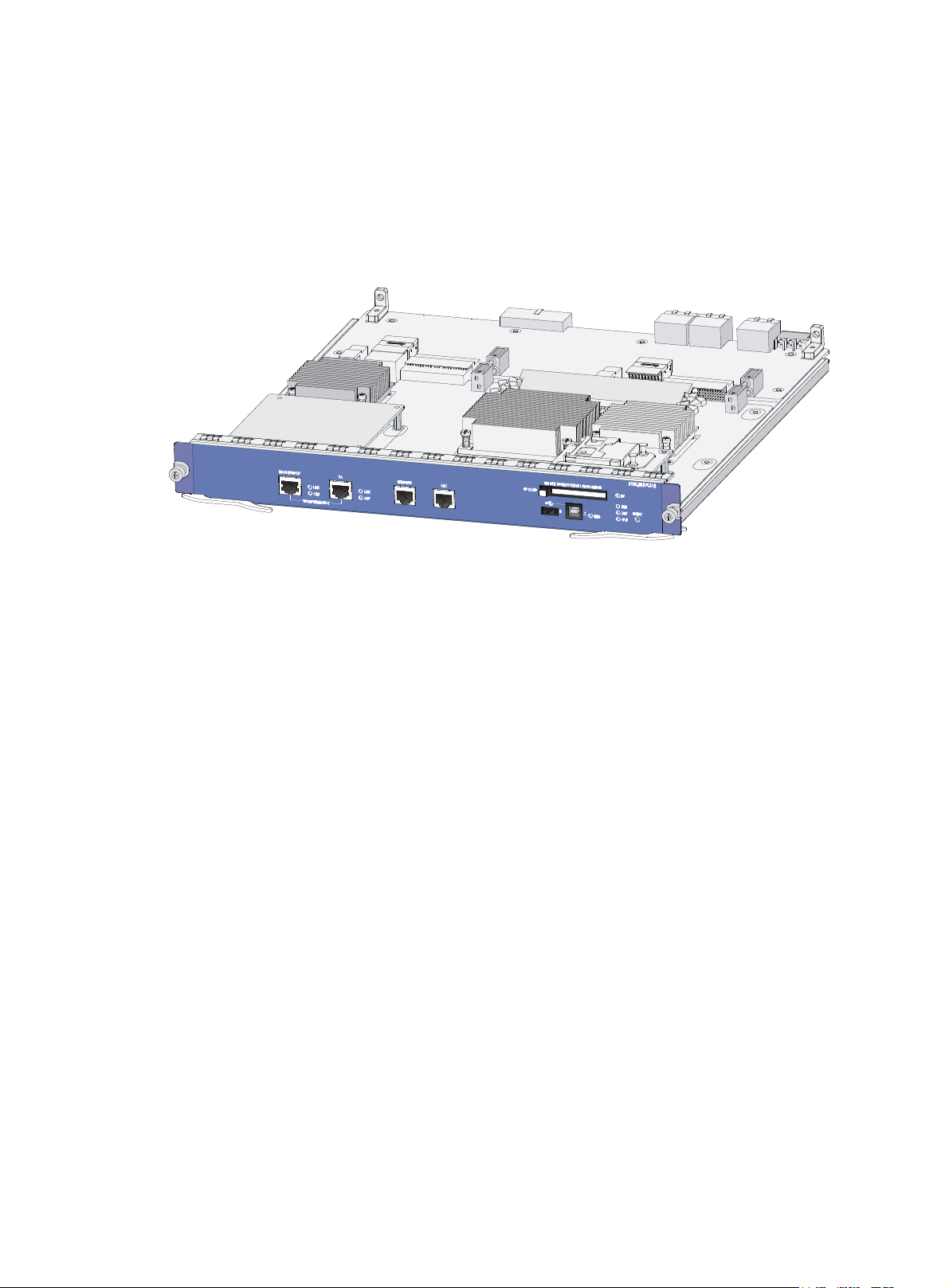
1 Appearance
Figure 1 Appearance of the NSQ1MPUA0
BOM:3123A13Q
2 Specifications
The NSQ1MPUA0 works with other service cards to provide the firewall feature. In addition, the
NSQ1MPUA0 is used to upgrade and maintain the firewall software.
The NSQ1MPUA0 provides, from left to right on its front panel, one management Ethernet port, one HA
port, one Console port, one AUX port, one external CF card slot, two USB interfaces, LEDs, and one
Reset button.
i
Page 2
Manual Version:6PW103-20121130
p
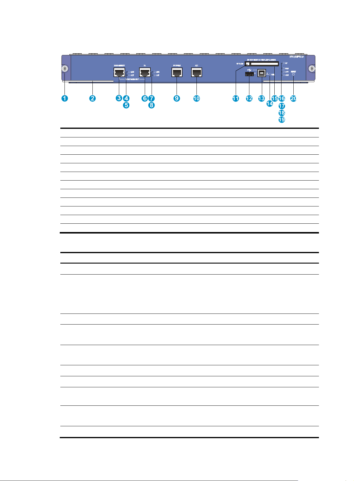
Figure 2 Front panel of the NSQ1MPUA0
(1) Captive screw (2) Ejector lever
(3) Management Ethernet port-10/100/1000BASE-T (MANAGEMENT)
(4) Link status LED of the management Ethernet port (LINK)
(5) Data reception/transmission LED of the management Ethernet port (ACT)
(6) HA port-10/100/1000BASE-T (HA)
(8) Data reception/transmission LED of the HA port (ACT)
(10) AUX port (AUX) (11) CF card eject button (CF CARD)
(12) USB interface 0 (0) (13) USB interface 1 (1)
(14) USB interface 1 LED (USB1) (15) CF card slot
(16) CF card LED (CF) (17) Run LED (RUN)
(18) Active LED of the MPU (ACT) (19) Alarm LED (ALM)
(20) Reset button (RESET)
BOM:3123A13Q
(7) Link status LED of the HA port (LINK)
(9) Console port (CONSOLE)
Table 1 NSQ1MPUA0 specifications
Item S
Flash 4 MB
Memory type and size
NVRAM 256 KB
Console port
AUX port
Management Ethernet port 1 (10Base-T/100Base-TX/1000Base-T)
HA port 1 (10Base-T/100Base-TX/1000Base-T)
CF card
USB interfaces
ecification
DDR2 SDRAM
2 memory slots
4 GB (default); two 2 GB memory chips
Memory modules must be used in pairs with the same size.
1
9600 bps (default) to 115200 bps
1
9600 bps (default) to 115200 bps
• 256 MB by default for the built-in CF card
• 256 MB, 512 MB, or 1 GB for an optional external CF card
2 (USB 0: operating in the host mode; USB 1: operating in the device mode)
Reserved for future use
Dimensions (H × W × D) 45.2 × 399.2 × 434.6 mm (1.78 × 15.72 × 17.11 in)
ii
Page 3

Manual Version:6PW103-20121130
p
Item Specification
Power consumption 81 W
Reset button 1
Hot swapping Not supported
Table 2 Description of the LEDs on the NSQ1MPUA0
BOM:3123A13Q
LED Color Status Descri
Off No power input or the MPU is faulty.
Slow flashing (1 Hz) The MPU is operating properly.
RUN Green
LINK Green
ACT Yellow
ALM Red
Fast flashing (8 Hz)
Resetting
Off No link is present on the management Ethernet port.
On A link is present on the management Ethernet port.
Off
On
Off The system is operating properly with no alarms.
On
Fast flashing (8 Hz)
The application software is being loaded (in this state, never
power off the device or hot-swap the MPU; otherwise the
MPU may be damaged), or the MPU is not working.
The LED goes off after resetting and blinks fast after the
system startup.
No data is being transmitted or received on the
management Ethernet port.
Data is being transmitted or received on the management
Ethernet port.
A fault has occurred to the system or the available power is
not enough. In this state, check the system log immediately.
A critical fault has occurred to the system. In this state,
handle the fault immediately.
tion
LINK Green
ACT Yellow
USB Green
CF Green
Off No link is present on the HA port.
On A link is present on the HA port.
Off No data backup occurred on the HA port.
On The HA port is backing up data.
Off No host is connected to the device-mode USB interface.
On
Flashing
Off No CF card is present or the CF card is not recognizable.
On
Flashing
A host is in connection with the device-mode USB interface.
The USB cable can be unplugged in this state.
Data is being transmitted or received through the
device-mode USB interface. Do not unplug the USB cable in
this state.
A CF card is in position and has passed the power-on
self-test (POST).
The system is accessing the CF card. Do not remove the CF
card in this state.
iii
Page 4

Manual Version:6PW103-20121130
3 Installing and removing the NSQ1MPUA0
IMPORTANT:
MPUs are not hot-swappable. Before you remove MPUs, power off the firewall.
3.1 Installing the NSQ1MPUA0
1. Locate the slot to install the MPU.
2. Remove the filler panel from slot 0.
3. Gently push the MPU into the slot along the slide rails until the positioning pins on the MPU are
seated in the positioning holes on the backplane. Then push the ejector levers inward to lock the
MPU in position.
Figure 3 Insert the NSQ1MPUA0
BOM:3123A13Q
4. Fasten the captive screws on the MPU with a Phillips screwdriver.
5. The RUN LED (green) flashes fast (at 8 Hz). It flashes slowly (at 1 Hz) after the MPU application is
loaded. This means that the MPU is operating properly.
3.2 Removing the NSQ1MPUA0
1. Face the front panel of the firewall.
2. Loosen the captive screws with a Phillips screwdriver until all pressure is released.
3. Pull the two ejector levers at both ends of the MPU outward to release the MPU, and then gently
pull the MPU out along the slide rails.
Put the removed MPU in an antistatic bag.
4. Install a new MPU.
For how to install an MPU, see "Installing the NSQ1MPUA0."
iv
Page 5

Manual Version:6PW103-20121130
If no new MPU is to be installed, install a filler panel.
4 Upgrading Firewall Software
You can upgrade the firewall software by using the Console port and management Ethernet
interface/HA interface on the NSQ1MPUA0. For the detailed upgrade procedure, see Release Notes.
5 Obtaining documentation
For card installation, see the H3C SecPath F5000-A5 Firewall Installation Guide.
If the firewall software version does not match, contact the vendor or the integrator for the right version.
Take the following steps to get the latest documentation from the H3C website at www.h3c.com.
BOM:3123A13Q
• Go to http://www.h3c.com/portal/Technical_Documents
Documents > Technical Documents on the top navigation bar at http://www.h3c.com
• Choose the desired product category and model.
Copyright © 2012 Hangzhou H3C Technologies Co., Ltd.
, or click Technical Support &
.
v
 Loading...