

Page 1

H3C SecBlade IPS Cards
User Manual
Hangzhou H3C Technologies Co., Ltd.
http://www.h3c.com
Document version: 5PW104-20101210
Page 2

Copyright © 2008-2010, Hangzhou H3C Technologies Co., Ltd. and its licensors
All rights reserved
No part of this manual may be reproduced or transmitted in any form or by any means without prior
written consent of Hangzhou H3C Technologies Co., Ltd.
Trademarks
H3C,
, Aolynk, , H3Care,
, TOP G, , IRF, NetPilot, Neocean, NeoVTL,
SecPro, SecPoint, SecEngine, SecPath, Comware, Secware, Storware, NQA, VVG, V
2
G, VnG, PSPT,
XGbus, N-Bus, TiGem, InnoVision and HUASAN are trademarks of Hangzhou H3C Technologies Co.,
Ltd.
All other trademarks that may be mentioned in this manual are the property of their respective owners
Notice
The information in this document is subject to change without notice. Every effort has been made in the
preparation of this document to ensure accuracy of the contents, but all statements, information, and
recommendations in this document do not constitute the warranty of any kind, express or implied.
Page 3

Preface
The H3C SecBlade IPS Cards User Manual describes the SecBlade IPS cards’ overview, features, and
login methods, and the configurations on the switches and routers that hold the cards.
This preface includes:
•
Audience
•
Conventions
•
About the H3C SecBlade IPS Cards Document Set
•
Obtaining documentation
•
Technical support
•
Documentation feedback
Audience
This documentation is intended for:
• Network planners
• Field technical support and servicing engineers
• Network administrators working with the H3C SecBlade IPS cards
Conventions
This section describes the conventions used in this documentation set.
Command conventions
Convention Description
Boldface Bold text represents commands and keywords that you enter literally as shown.
Italic Italic text represents arguments that you replace with actual values.
[ ] Square brackets enclose syntax choices (keywords or arguments) that are optional.
{ x | y | ... }
Braces enclose a set of required syntax choices separated by vertical bars, from which
you select one.
[ x | y | ... ]
Square brackets enclose a set of optional syntax choices separated by vertical bars, from
which you select one or none.
{ x | y | ... } *
Asterisk marked braces enclose a set of required syntax choices separated by vertical
bars, from which you select at least one.
[ x | y | ... ] *
Asterisk marked square brackets enclose optional syntax choices separated by vertical
bars, from which you may select multiple choices or none.
&<1-n>
The argument or keyword and argument combination before the ampersand (&) sign can
be entered 1 to n times.
# A line that starts with a pound (#) sign is comments.
Page 4
GUI conventions
Convention Description
Boldface
Window names, button names, field names, and menu items are in Boldface. For
example, the New User window appears; click OK.
> Multi-level menus are separated by angle brackets. For example, File > Create > Folder.
Symbols
Convention Description
WARNING
An alert that calls attention to important information that if not understood or followed can
result in personal injury.
CAUTION
An alert that calls attention to important information that if not understood or followed can
result in data loss, data corruption, or damage to hardware or software.
IMPORTANT
An alert that calls attention to essential information.
NOTE
An alert that contains additional or supplementary information.
TIP
An alert that provides helpful information.
About the H3C SecBlade IPS Cards Document Set
The H3C SecBlade IPS cards documentation set includes:
Category Documents Purposes
Marketing brochures Describe product specifications and benefits.
Product description and
specifications
Technology white papers
Provide an in-depth description of software features
and technologies.
Card Manual
Provides the card types, hardware specifications,
and interface attributes.
Software Upgrade Guide Guides you through the software upgrade.
Installation and
commissioning
License Registration and
Activation Guide
Provides the configuration procedure and guidelines
to activate and register the license.
User Manual
Describes the data forwarding procedure of the card
sand basic network configuration with switches
Web-Based
Configuration Guide
Describe how to configure and deploy the cards
Typical Configuration
Example
Provide configuration examples and instructions of
the cards.
Configuration Guide
Service configuration
Command Reference
Configure and maintain the card at the CLI
Page 5

Obtaining documentation
You can access the most up-to-date H3C product documentation on the World Wide Web at
http://www.h3c.com.
Click the links on the top navigation bar to obtain different categories of product documentation:
[Technical Support & Documents > Technical Documents] – Provides hardware installation, software
upgrading, and software feature configuration and maintenance documentation.
[Products & Solutions] – Provides information about products and technologies, as well as solutions.
[Technical Support & Documents > Software Download] – Provides the documentation released with the
software version.
Technical support
customer_service@h3c.com
http://www.h3c.com
Documentation feedback
You can e-mail your comments about product documentation to info@h3c.com.
We appreciate your comments.
Page 6

i
Contents
Overview ······································································································································································ 1
Introduction to the Manual ···············································································································································1
Related Manuals································································································································································1
SecBlade IPS Cards Overview···································································································································· 2
Introduction ········································································································································································2
Main Characteristics·························································································································································2
Main Functions ··································································································································································3
Features········································································································································································· 5
Feature List ·········································································································································································5
Login·············································································································································································· 6
Switch/Router and SecBlade IPS Card Network Configuration···············································································9
LSWM1IPS10 Card Configuration ·································································································································9
Configuration Overview ··········································································································································9
Configuration Procedure······································································································································· 10
Configuration Example ·········································································································································14
LSQ1IPSSC0 Card Configuration (Only for the S7500E Switch and Supporting OAA Configuration)·············· 17
Configuration Overview ······································································································································· 17
Configuration Procedure······································································································································· 18
Configuration Example ·········································································································································22
LSB1IPS1A0 Card Configuration ································································································································· 27
Configuration Overview ······································································································································· 27
Configuration Procedure······································································································································· 28
Configuration Example ·········································································································································31
LSR1IPS1A1 Card Configuration ·································································································································35
Configuration Overview ······································································································································· 35
Configuration Procedure······································································································································· 36
Configuration Example ·········································································································································40
LST1IPS1A1 Card Configuration·································································································································· 44
Configuration Overview ······································································································································· 44
Configuration Procedure······································································································································· 45
Configuration Example ·········································································································································49
SPE-IPS-200 Card Configuration ·································································································································· 53
Configuration Overview ······································································································································· 53
Configuration Procedure······································································································································· 53
Configuration Example ·········································································································································57
IM-IPS Card Configuration ············································································································································ 60
Configuration Overview ······································································································································· 60
Configuration Procedure······································································································································· 61
Configuration Example ·········································································································································64
Appendix-OAA Configuration ··································································································································69
Overview········································································································································································· 69
ACFP Architecture ················································································································································· 69
OAA Collaboration··············································································································································· 70
ACFP Management ··············································································································································· 70
Configuring OAA Client················································································································································ 70
OAA Configuration Example········································································································································ 72
Page 7

ii
Index ···········································································································································································78
Page 8

1
Overview
Introduction to the Manual
This manual mainly consists of the following chapters:
•
SecBlade IPS Cards Overview: Describes the functions and service features of the SecBlade IPS
cards.
•
Features: Describes the features of the SecBlade IPS cards. For how to configure these features, see
the H3C Intrusion Prevention System Web-Based Configuration Guide.
•
Login: Describes how to log in to the web interface of the SecBlade IPS cards.
•
Switch/Router and SecBlade IPS Card Network Configuration: Describes the work flow and
principles of data forwarding between a switch/router and a SecBlade IPS card, presents the
configurations on the switch/router and the SecBlade IPS card, and provides configuration
examples.
•
Appendix-OAA Configuration: Describes OAA basic principles and configuration procedure, and
gives configuration examples.
Related Manuals
For the installation, startup and configuration, software upgrade and hardware maintenance of the
SecBlade IPS cards, see the H3C SecBlade Cards Software Upgrade Guide and the hardware
documents of the devices using the cards, such as the installation guides of
S5800/S5820X/S7500E/S9500/S9500E/S12500 series switches and SR6600/SR8800 routers.
Follow these steps to obtain the product documentation from www.h3c.com:
• Select Technical Support & Document > Technical Documents from the home page.
• Select a device type, and then you can view the related manuals.
Page 9

2
SecBlade IPS Cards Overview
Introduction
H3C Intrusion Prevention System (IPS) products fall into two categories.
1. H3C SecPath T series
• T200 series: T200, T200-E (enhanced), T200-A (advanced), T200-M (middle), T200-S (standard)
• T1000 series: T1000-A (advanced), T1000-M (middle), T1000-S (standard), T1000-C (compact)
• T5000 series: T5000-S3
2. H3C SecBlade IPS card series
• LSWM1IPS10: Applicable to H3C S5800/S5820X series switches that support OAA
• LSQ1IPSSC0: Applicable to H3C S7500E series switches
• LSB1IPS1A0: Applicable to H3C S9500 series switches
• LSR1IPS1A1: Applicable to H3C S9500E series switches
• LST1IPS1A1: Applicable to H3C S12500 series switches
• SPE-IPS-200: Applicable to H3C SR6600 routers
• IM-IPS: Applicable to H3C SR8800 routers
In this manual, the switches and routers that support ISP cards are referred to as main network devices.
This manual mainly describes the features and typical configuration of the two types of H3C SecBlade
IPS cards.
H3C IPS products are mainly online deployed on the key paths of user networks and perform Layer 2
through Layer 7 data analysis in real time to precisely identify and stop/limit various attacks and network
abuses such as hackers, worms, viruses, Trojans, DoS/DDoS, scans, spyware, protocol anomalies,
phishing, P2P, IM, and network games, and to ensure the security, service continuity and performance of
network applications.
H3C IPS products can also be deployed in bypass mode to implement intrusion detection. In addition,
H3C IPS products provide powerful, practical bandwidth management and URL filtering functions.
H3C SecBlade IPS cards are based on the latest hardware platform and architecture of H3C. They
support distributed deployment, centralized management and flexible scalability, and can be managed
using a web browser. H3C SecBlade IPS cards can be inserted to the main network devices to satisfy the
traffic management needs of users.
Main Characteristics
• SecBlade IPS cards enable main network devices to provide network security services without
affecting data forwarding performance.
• SecBlade IPS cards are based on the H3C Open Application Architecture (OAA). A SecBlade IPS
card is connected to a main network device through an internal 10GE Ethernet interface. The
wire-speed forwarding capability of the back card of the main network device ensures smooth data
exchange with the SecBlade IPS card.
Page 10

3
• SecBlade IPS cards adopt the multi-core high-performance processor and high-speed memory, and
thus can ensure the processing of security services without affecting the normal operation of the
main network device.
• Multiple slots on the main network device can accommodate SecBlade IPS cards. You can plug
multiple SecBlade IPS cards in to a main network device for service expansion, meeting the update
requirements of enterprise and carrier networks.
Main Functions
SecBlade IPS cards provide the following main functions.
1. Application layer based attack detection and defense
SecBlade IPS cards adopt the proprietary engine of H3C, Full Inspection with Rigorous State Test (FIRST ).
The FIRST engine provides multiple detection technologies, and improves the preciseness of attack
detection by implementing full inspection based on rigorous state. It adopts concurrent detection
technology and supports flexible hardware&sofware configurations, greatly improving the intrusion
detection performance. The FIRST engine integrates protocol identification and characteristic matching.
It uses protocol identification to identify application layer protocols and detect abnormal protocols, and
uses characteristic matching to determine attacks. Only the traffic matching the specific attacking
characteristics of a detected abnormal protocol is considered as an attack. This method greatly improves
inspection preciseness and reduces false positive and false negative rates.
2. DDoS defense
SecBlade IPS cards can provide Distributed Denial of Service (DDoS) defense in various network
environments by performing deep analysis of DDoS attacks (including SYN flood, RST flood, ACK flood,
UDP flood, ICMP flood, Connection flood, CPS flood, DNS query flood and HTTP get flood), and using
advanced defense algorithms.
3. AV function
SecBlade IPS cards are integrated with the KasperSky anti-virus engine and virus definitions. The engine
adopts advanced anti-virus technologies such as the second generation heuristic code analysis method,
iChecker real-time monitoring and unique script virus interception, and can scan and kill viruses of
various types, such as file type, network type and mixed type. In addition, it incorporates the next
generation virtual machine unpack engine and behavior estimation technologies to kill derived viruses
and unknown viruses accurately.
4. URL filtering
SecBlade IPS cards provide the URL filtering function, which allows you to define URL filtering rules that
support regular expression to filter specific web pages.
5. Application based bandwidth control
Based on protocol identification, which can identify more than 1000 protocols, SecBlade IPS cards can
perform flexible bandwidth control to ensure bandwidth for critical applications by limiting non-critical
applications from using bandwidth.
6. Various actions
SecBlade IPS cards provide various actions to be taken on detected abnormal traffic, including stop,
restrict, TCP reset, get original packets, redirect, isolate, report syslogs, and record local logs. You can
combine actions as needed, and SecBlade IPS cards also provide some commonly used action
combinations.
7. Unified management and policy assignment
Page 11

4
SecBlade IPS cards support local and distributed management modes. For a network with one or a small
number of SecBlade IPS cards deployed, you can manage the cards through the web interface
embedded. For a network with a large number of SecBlade IPS cards deployed, you can implement
unified upgrade, monitoring, analysis and policy management for the cards through the H3C security
management center SecCenter.
Page 12

5
Features
Feature List
Table 1 Feature list of SecBlade IPS cards
Module Features
Web overview Device management User management
Network management High reliability Time table management
Actions management Log management IPS
URL filtering Anti-virus DDoS protection
Web Configuration
Bandwidth management Blacklist Reports
Commonly used network
application commands
Interface management
commands
Static route configuration
commands
CLI Configuration
Device management
commands
System basic
configuration commands
Encrypted P2P traffic
identification configuration
commands
Page 13
6
Login
With the web network management function, the administrator can manage and maintain a SecBlade
IPS card through the web interface.
Follow these steps to log in to the web interface of the SecBlade IPS card.
1. Connect the SecBlade IPS card to a PC
• For the LSWM1IPS10 card
Prepare a console cable with a RJ 45 connector at one end and a DB9 female connector at the other.
Connect the RJ 45 connector to the console port of the switch, and connect the DB9 female connector to
the serial port of the PC. Then connect the management port of the SecBlade IPS card to the network
interface of the PC by using a crossover Ethernet cable.
Figure 1 Connect the SecBlade IPS card to a PC
PC
Switch & IPS card
Console cable
Ethernet cable
Serial interface
Ethernet interface
Management interface
(IPS card)
Console interface
(Switch)
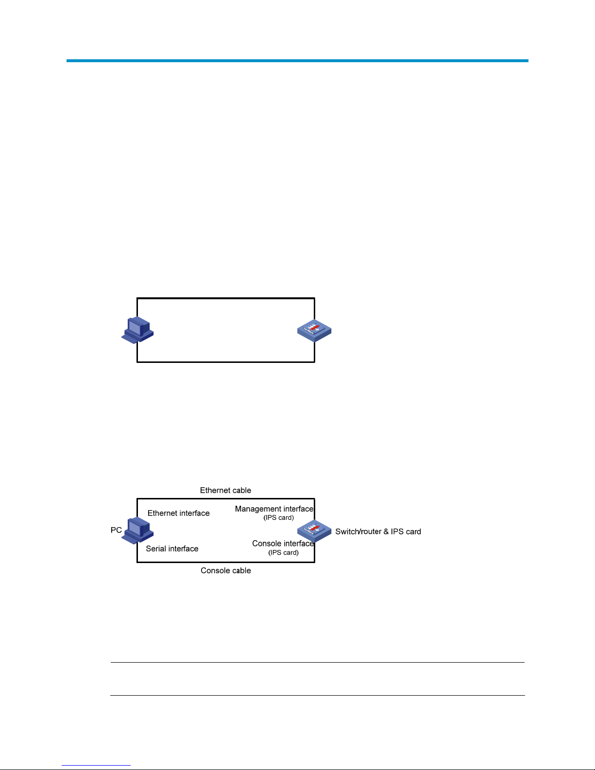
• For a non-LSWM1IPS10 card
Prepare a console cable with a RJ 45 connector at one end and a DB9 female connector at the other.
Connect the RJ 45 connector to the console port of the SecBlade IPS card, and connect the DB9 female
connector to the serial port of the PC. Then connect the management port of the SecBlade IPS card to the
network interface of the PC by using a crossover Ethernet cable.
Figure 2 Connect the SecBlade IPS card to a PC
2. Set terminal parameters on the PC
Run the terminal emulator on the PC (for example, Terminal of Windows 3.X, hyper terminal of Windows
9X and Windows XP).
Set the bits per second to 9600, data bits to 8, parity to none, stop bits to 1, and flow control to none,.
NOTE:
Settings of terminal parameters depend on the device model.
Page 14

7
3. Enter the CLI of the device
• For the LSWM1IPS10 card
Power on the switch. As the S5800 and S5820X are centralized stacking devices, you need to execute
the command for logging into the OAP system before you can enter the CLI of the LSWM1IPS10 card.
# Enter the CLI of the LSWM1IPS10 card.
<Sysname> oap connect slot 1 system SubSlot3
Press CTRL+K to quit.
Connected to SubSlot3!
The PC then displays the Power On Self Test (POST) information of the IPS card. After the POST, you are
prompted to enter the password (the default password is H3C, which is case-sensitive). Enter the correct
password to enter the CLI of the IPS card.
• For a non-LSWM1IPS10 card
Power on the switch or router. The PC shows the POST information of the IPS card. After the POST, you are
prompted to enter the system password, which defaults to H3C (case-sensitive). After you input the
correct password, you can enter the CLI of the IPS card.
4. Configure the management IP address of the IPS card (this step is optional; the default
management IP address is 192.168.1.1).
# Configure the management IP address of the IPS card (The default management interface of
LSWM1IPS10 card is meth 0/0, and that of other cards is meth 0/2. The following takes management
interface meth0/2 as an example.)
<Sysname> system-view
[Sysname] interface meth0/2 ←Enter the management interface
[Sysname-if] ip address 10.153.17.82 255.255.255.0 ←Configure the IP address and mask of
the management interface as 10.153.17.82/24
[Sysname-if] undo shutdown←Enable the management interface
The system automatically saves the above configuration.
5. Configure an IP address for the PC to ensure connectivity with the SecBlade IPS card.
Configure an IP address in the subnet 10.153.17.0/24 (except for 10.153.17.82), for example,
1 0 .15 3 .1 7. 8 3 .
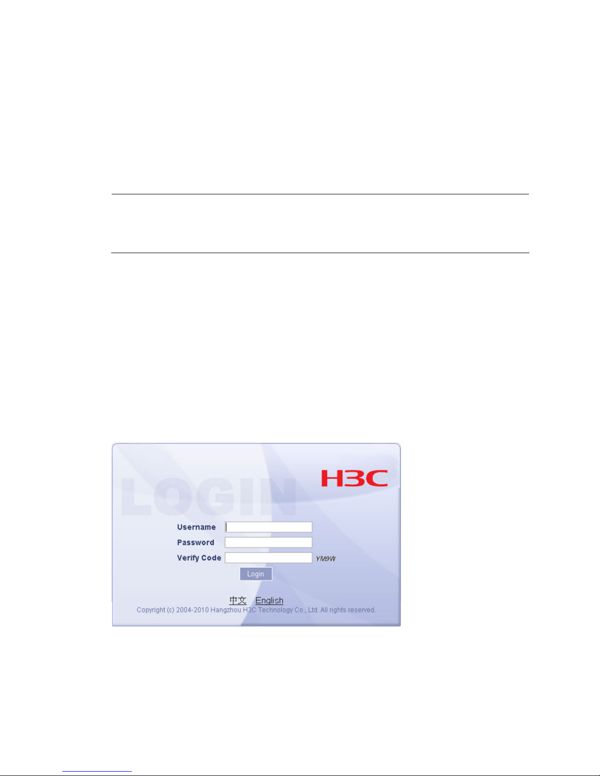
6. Open the browser to login
Open the IE browser on the PC, and input the IP address 10.153.17.82 to enter the login interface shown
in
Figure 3.
On the login interface, input the default user name admin and the default password admin, and click
Login to log in to the device through the web interface.
Page 15

8
Figure 3 web interface login interface
By default, the IPS card has HTTPS enabled, but does not have HTTP enabled. Therefore, for the first login,
only the HTTPS method is available. After the first login through HTTPS, you can enable HTTP as follows:
select System Management > Network Management > Management Interface from the navigation tree
to enter the page shown in
Figure 4.
Figure 4 HTTP/HTTPS configuration
Select the checkbox before HTTP and click Apply. A confirmation dialog box pops up, showing
“Changing the IP address of the management interface may break the network connection. Continue?”.
Click OK on the dialog box to complete configuration.
WARNING!
• The PC in
Figure 2 is a common configuration terminal and is not required to be a web network
management terminal.
• Do not log in to the web interface through both HTTP and HTTPS at the same time from a PC.
After the first login, H3C recommends changing the default password. For more information, see
User
Management
in the
H3C Intrusion Prevention System Web-Based Configuration Guide.
Page 16

9
Switch/Router and SecBlade IPS Card Network
Configuration
NOTE:
For more information about the commands used in this chapter, see the Configuration Guides and
Command References shipped with switch and router that installated the SecBlade IPS Card.
LSWM1IPS10 Card Configuration
NOTE:
The LSWM1IPS10 card is only for S5800&S5820X series switches and supports the OAA feature.
Configuration Overview
The switch and the SecBlade IPS card are connected through internal 10GE interfaces. The switch uses
VLAN interfaces to perform Layer 3 forwarding. Configure redirection on the internal and external
network interfaces of the switch to redirect incoming IP packets to be forwarded through the VLAN
interfaces to the internal 10GE interface connected to the SecBlade IPS card. The switch performs normal
Layer-3 forwarding to the packets and then sends them to the SecBlade IPS card through its internal
10GE interface. The detailed data forwarding process is as follows.
From internal network to external network
1. A packet from the internal network enters the switch.
2. The switch reprocesses the packet for Layer 3 forwarding, during which the switch inserts an
outgoing VLAN tag in to the packet.
3. After the Layer 3 preprocessing, the switch redirects the packet to the SecBlade IPS card according
to the receiving port, the incoming VLAN and the outgoing port.
4. After reprocessing the packet, the SecBlade IPS card forwards the packet back to the switch.
5. The switch forwards the packet out its external network interface.
From external network to internal network
1. A packet from the external network enters the switch.
2. The switch preprocesses the packet for Layer 3 forwarding, during which the switch removes the
incoming VLAN tag from the packet.
3. After the Layer 3 preprocessing, the switch redirects the packet to the SecBlade IPS card according
to the receiving port, the incoming VLAN and the outgoing port.
4. After reprocessing the packet, the SecBlade IPS card forwards the packet back to the switch.
5. The switch forwards the packet out its internal network interface.
Page 17

10
Configuration Procedure
Configuring the switch
Configure the switch as follows.
• Configure the Management Information Base (MIB) style of the switch.
• Configure SNMP parameters. Configure SNMPv3 users and adopt non-authentication and
non-encryption.
• Enable the ACFP server and the ACSEI server.
• Configure a VLAN, VLAN 100, for example, which must not conflict with any existing VLANs on the
switch, and configure an IP address for the VLAN interface.
• Configure the internal 10GE interface as an Access interface, add it to a VLAN for example VLAN
100 (which must be consistent with the VLAN ID configured on the OAA configuration page of the
SecBlade IPS card), and configure the interface’s port-connect-mode as extended.
• Save the configuration.
Follow these steps to configure the switch:
To do… Use the command… Remarks
Enter system view system-view —
Configure the MIB style of the
switch
mib-style [ new |
compatible ]
Required
• new: Specifies the MIB style H3C new.
With this style, both the sysOID and
private MIB of the switch are located
under the H3C enterprise ID 25506.
• compatible: Specifies the MIB style H3C
compatible. With this style, the sysOID
of the switch is located under the H3C
enterprise ID 25506, and the private
MIB is located under the enterprise ID
2011.
By default, the MIB style of the switch is
new.
You need to reboot the switch to validate
this configuration (you can reboot the
switch after completing all configurations).
CAUTION:
Make sure that the switch’s the MIB style is
new. If you specify compatible for the switch,
the switch cannot work normally.
Enable SNMP agent snmp-agent
Required
Disabled by default.
Set the SNMP version
snmp-agent sys-info
{ contact sys-contact |
location sys-location |
version { all | { v1 | v2c |
v3 }* } }
Required
The SecBlade IPS card supports only
SNMPv3.
By default, SNMPv3 applies.
Page 18

11
To do… Use the command… Remarks
Create an SNMP group and set its
access right
For SNMP v3:
snmp-agent group v3
group-name
[ authentication | privacy ]
[ read-view read-view ]
[ write-view write-view ]
[ notify-view notify-view ]
[ acl acl-number ]
Required
By default, the SNMP group configured
with the snmp-agent group v3 command
uses non-authentication and
non-encryption.
Create or update a MIB view to
specify the MIB objects that the
NMS can access
snmp-agent mib-view
{ excluded | included }
view-name oid-tree [ mask
mask-value ]
Required
The default view is ViewDefault.
Add a user to the SNMP group
snmp-agent usm-user v3
user-name group-name
[ [ cipher ]
authentication-mode
{ md5 | sha }
auth-password
[ privacy-mode { des56 |
aes128 } priv-password ] ]
[ acl acl-number ]
Required
If you execute this command for the same
user repeatedly, the last configuration takes
effect.
Enable the ACFP server acfp server enable
Required
Disabled by default.
Enable the ACSEI server acsei server enable
Required
Disabled by default.
Create a VLAN
and enter VLAN
view
vlan { vlan-id1 [ to
vlan-id2 ] | all }
Required
Return to system
view
quit Required
Enter the specified
VLAN interface
view
interface vlan-interface
vlan-interface-id
Required
Before creating the VLAN interface, you
need to create the corresponding VLAN.
Otherwise, the VLAN interface cannot be
created.
Configure an IP
address and mask
for the VLAN
interface
ip address ip-address
{ mask | mask-length }
[ sub ]
Required
Not configured by default.
In general, you need to configure only one
IP address for a VLAN interface. To enable
a VLAN to connect multiple subnets, you
can configure multiple IP addresses for the
VLAN interface. One of them is the primary
IP address and others are secondary IP
addresses. On the S5800&S5820X series
switches, a VLAN interface can have up to
10 IP addresses configured.
Configure
the internal
10GE
interface
Return to system
view
quit Required
Page 19

12
To do… Use the command… Remarks
Enter the view of
the 10GE interface
connected to the
SecBlade IPS card
interface
Ten-GigabitEthernet
interface-number
Required
Configure the link
type of the
interface as access
port link-type access
Required
By default, the link type of an interface is
access.
Add the interface
to a VLAN
port access vlan vlan-id
Required
Add the internal interface to the
management VLAN.
Configure the
extended port
connection mode
for the port
port connection-mode
extend
Required
Return to system
view
quit Required
Save the configuration to a
configuration file
save [ file-name | [ safely ]
Required
Configuring the SecBlade IPS card
Configure the SecBlade IPS card as follows.
• Configure the IP address of the management interface at the CLI and use the IP address to login to
the web interface of the SecBlade IPS card.
• Configure the internal interface and the OAA client and test its connectivity to the switch.
• Create security zones and add the interfaces of the switch to corresponding security zones.
• Create a segment and add internal and external zones to the segment.
Follow these steps to configure the SecBlade IPS card:
To do… Use the command… Remarks
Configure redirection from
the device to the OAP system
(for centralized stacking
devices/distributed devices)
oap connect [ slot slot-number ] system
system-name
Required
Perform this operation in user
view to enter the CLI of the
SecBlade IPS card.
Enter system view system-view —
Enter management interface
view
interface meth interface-number Optional
Configure an IP address for
the management interface
ip address ip-address mask
Optional
By default, the IP address of the
management interface meth0/0 is
192.168.1.1.
Enable the management
interface
undo shutdown
Required
Disabled by default.
Page 20

13
To do… Use the command… Remarks
Use the IP address of the
management interface to
login to the web interface of
the SecBlade IPS card
—
Required
The default username and
password are both admin.
Configure the
OAA client
and internal
interface
Select System Management > Device
Management > OAA Configuration. Input
parameters in OAA Client Configuration
and Internal Interface Configuration to
complete OAA configuration.
Required
Configure
OAA
Test the
connectivity
Click the Test Connectivity button to test
the connectivity between the OAA client
and the server.
Required
Create security zones
Select System Management > Network
Management > Security Zone. Use the
Add button to create security zones and
add the interfaces of the S5800/S5820X
switch to the security zone.
Required
The interface list of the switch is
sent to the OAA board (the
SecBlade IPS card in this case),
and you can add interfaces to
security zones.
Create a segment
Select System Management > Network
Management > Segment Configuration.
Click Add Segment. Select a segment
number, the internal zone, and the
external zone.
Required
You need to specify the internal
interface when creating the
segment. The internal interface
connects to the switch.
Displaying the configuration
After completing above configurations, you can use the display command in any view of the SecBlade
IPS card to view forwarding information on the internal 10GE interface and verify you configurations.
To do… Use the command…
Display the running status and forwarding
information of the 10GE interface
display interface [ interface-name ]
Use the following commands on the switch to display ACFP information.
To do… Use the command…
Display the ACFP server information display acfp server-info
Display the ACFP client information display acfp client-info [ client-id ]
Display the ACFP policy information
display acfp policy-info [ client client-id [ policy-index ] |
dest-interface interface-type interface-number | global |
in-interface interface-type interface-number | out-interface
interface-type interface-number ] [ active | inactive ]
Display the ACFP rule information
display acfp rule-info { global | in-interface [ interface-type
interface-number ] | out-interface [ interface-type
interface-number ] | policy [ client-id policy-index ] }
Page 21
14
Configuration Example
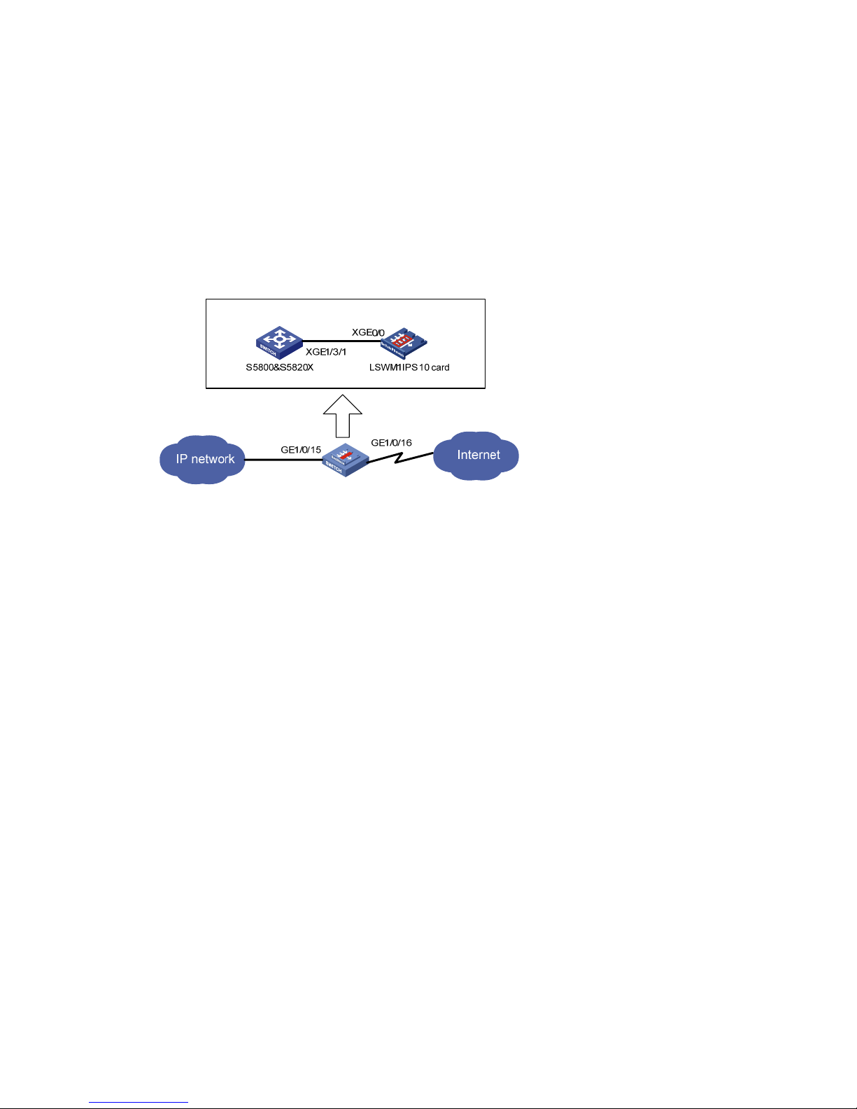
Network requirements
As shown in Figure 5, the switch has a SecBlade IPS card installed on slot 3. The switch uses
GigabitEthernet 1/0/15 to connect to the internal network, uses GigabitEthernet 1/0/16 to connect to
the external network, and uses its internal interface Ten-GigabitEthernet 1/3/1 to connect to the
SecBlade card’s internal interface Ten-GigabitEthernet 0/0. Traffic received on the switch’s interfaces
GigabitEthernet 1/0/15 and GigabitEthernet 1/0/16 must be sent to the SecBlade IPS card for
inspection.
Figure 5 S5800&S5820X switch and the LSWM1IPS card
Configuration procedure
1. Configure the switch
# Configure the H3C new MIB style. That is, the sysOID and private MIB are both under H3C enterprise
ID 25506. You need to reboot the switch to validate the configuration (You can reboot the switch after
completing all configurations).
<Sysname> system-view
[Sysname] mib-style new
# Configure SNMPv3 parameters.
[Sysname] snmp-agent
[Sysname] snmp-agent sys-info version all
[Sysname] snmp-agent group v3 v3group_no read-view iso write-view iso
[Sysname] snmp-agent mib-view included iso iso
[Sysname] snmp-agent usm-user v3 v3user_no v3group_no
# Enable the ACFP server and the ACSEI server.
[Sysname] acfp server enable
[Sysname] acsei server enable
# Configure the internal interface.
• Create VLAN 100 and configure an IP address for the VLAN interface. Make sure the VLAN does
not conflict with any existing VLAN.
[Sysname] vlan 100
[Sysname-vlan100] quit
[Sysname] interface Vlan-interface100
[Sysname-Vlan-interface100] ip address 100.100.100.1 255.255.255.0
[Sysname-Vlan-interface100] quit
Page 22
15
• Configure the link type of the internal interface as access, add it to VLAN 100, which must be
consistent with the VLAN ID configured on the OAA configuration page of the SecBlade IPS card,
and configure its port-connect-mode as extended.
[Sysname] interface Ten-GigabitEthernet1/3/1
[Sysname-Ten-GigabitEthernet] port access vlan 100
[Sysname-Ten-GigabitEthernet] port connection-mode extend
[Sysname-Ten-GigabitEthernet] quit
# Save the configuration.
<Sysname> save
NOTE:
Make sure that the OAA card in sub-slot m of slot n corresponds to the switch’s internal interface
Ten-GigabitEthernet n/m/1. For example, the OAA card in sub-slot 3 of slot 1 corresponds to the switch’s
internal interface Ten-GigabitEthernet 1/3/1.
2. Configure the SecBlade IPS card
# Configure an IP address for the management interface and enable the management interface. This
configuration is optional. By default, the IP address of the management interface is 192.168.1.1. You can
also change this IP address through the web interface.
<Sysname> oap connect slot 1 system SubSlot3
<Sysname> system-view
[Sysname] interface meth0/0
[Sysname-if]ip address 192.168.0.11 255.255.255.0
[Sysname-if] undo shutdown
[Sysname-if] quit
# Log in to the web interface of the SecBlade IPS card. The username and password are both admin.
Figure 6 Log into the SecBlade IPS card
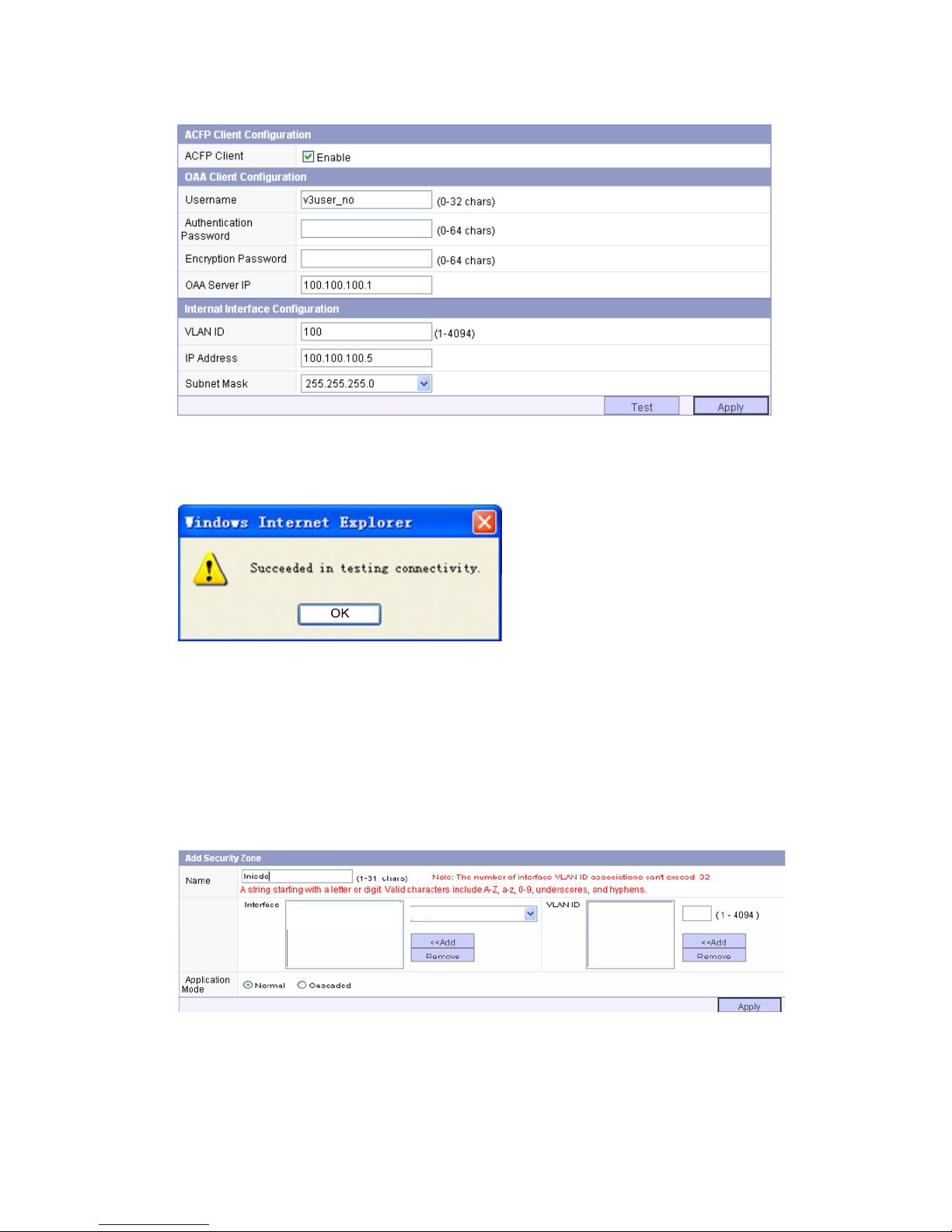
# Configure OAA.
• Configure the OAA client and the internal interface and test the connectivity to the switch.
Page 23
16
Figure 7 Configure the OAA client
After completing configuration, click Test. If the following message appears, the switch is reachable.
Figure 8 Connectivity test result
# Configure security zones.
After completing OAA configuration on the SecBlade IPS card and the S5800/S5820X, you can add
any physical ports of the S5800/S5820X to a security zone except the internal interface.
In this example, Create internal security zone Inside add GigabitEthernet 1/0/15 to the internal security
zone, as shown in
Figure 9. Create external security zone Outside and add GigabitEthernet 1/0/16 to
the external security zone in the same way.
Figure 9 Create a security zone
GigabitEthernet1/0/15
GigabitEthernet1/0/15
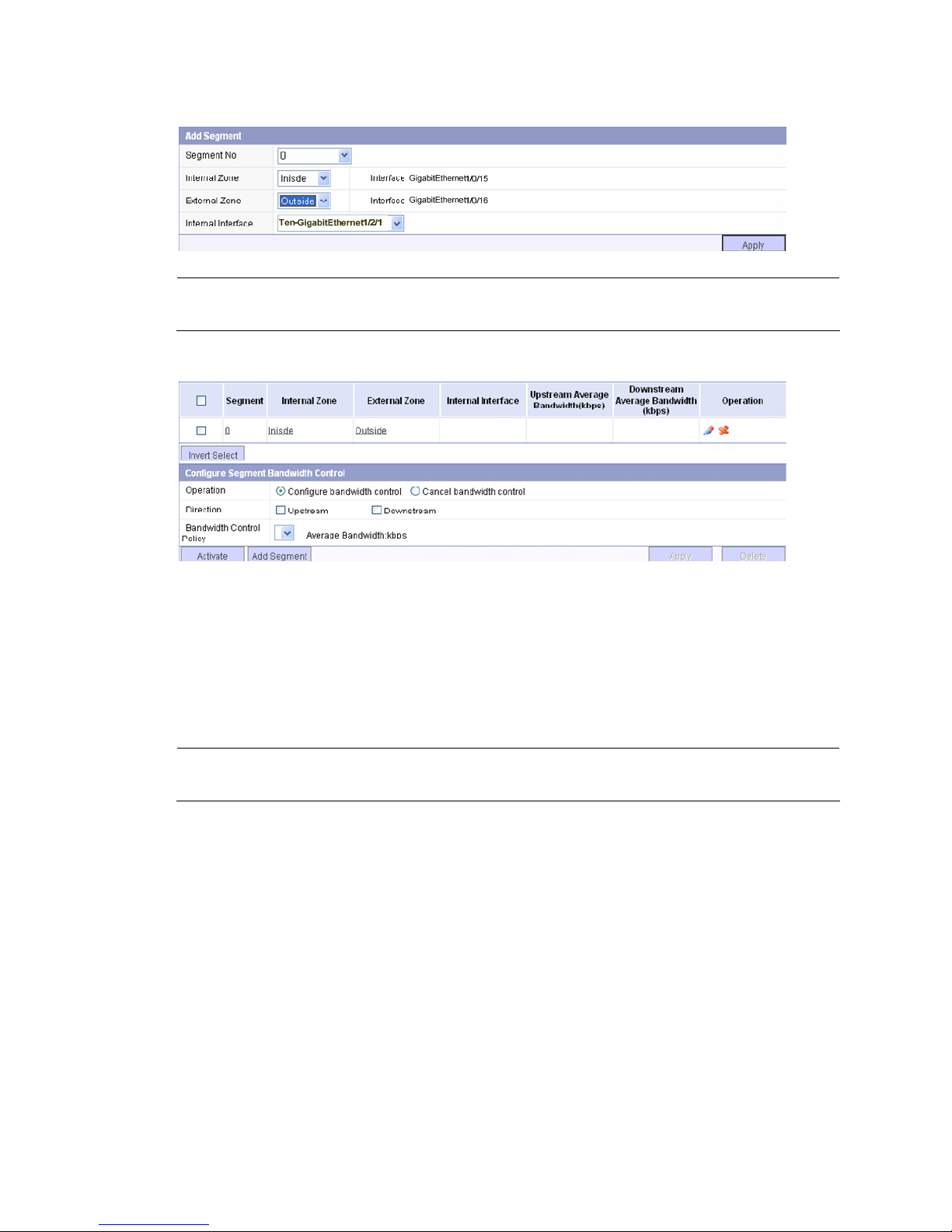
# Configure a segment.
Page 24
17
Figure 10 Create a segment
NOTE:
When creatin
g
a segment, you need to select the internal zone, external zone and the internal interface.
Figure 11 Configure the segment
TenGigabitEthernet1/2/1
LSQ1IPSSC0 Card Configuration (Only for the
S7500E Switch and Supporting OAA
Configuration)
NOTE:
The LSQ1IPSSC0 card is only for the S7500E switches and supports the OAA feature.
Configuration Overview
The switch and the SecBlade IPS card are connected through internal 10GE interfaces. With OAA
configured, the switch redirects traffic to the SecBlade IPS card through its 10GE interface automatically.
After processing the traffic, the SecBlade IPS card sends it back to the switch through its internal 10GE
interface, and the switch forwards the traffic. The detailed data forwarding process is as follows.
From internal network to external network
1. Packets from the internal network enter the switch.
2. The switch redirects the packets to the SecBlade IPS card.
3. After processing the packets, the SecBlade IPS card forwards them back to the switch.
4. The switch forwards the packets out its external network interface.
Page 25

18
From external network to internal network
1. Packets from the external network enter the switch.
2. The switch redirects the packets to the SecBlade IPS card.
3. After processing the packets, the SecBlade IPS card forwards them back to the switch.
4. The switch forwards the packets out its internal network interface.
Configuration Procedure
Configuring the switch
Configure the switch as follows.
• Configure the MIB style of the switch.
• Configure SNMP parameters. Configure SNMPv3 users and adopt non-authentication and
non-encryption.
• Enable the ACFP server and the ACSEI server.
• Configure a VLAN, VLAN 100, for example, which must not conflict with any existing VLANs on the
switch, and configure an IP address for the VLAN interface.
• Configure the internal 10GE interface as a trunk interface, configure its default VLAN ID as 100
(which must be consistent with the VLAN ID configured on the OAA configuration page of the
SecBlade IPS card), configure the interface to permit packets of VLAN 2 through VLAN 4094 to
pass, and configure its connection mode as extended.
• Configure the traffic switching mode of the main control board of the switch.
• Save the configuration and reboot the switch.
Follow these steps to configure the switch:
To do… Use the command… Remarks
Enter system view system-view —
Configure the MIB style of the
switch
mib-style [ new |
compatible ]
Required
• new: Specifies the MIB style H3C new.
With this style, both the sysOID and
private MIB of the switch are located
under the H3C enterprise ID 25506.
• compatible: Specifies the MIB style H3C
compatible. With this style, the sysOID of
the switch is located under the H3C
enterprise ID 25506, and the private MIB
is located under the enterprise ID 2011.
By default, the MIB style of the switch is new.
You need to reboot the switch to validate the
configuration (you can reboot the switch
after completing all configurations).
CAUTION:
Make sure that the switch’s the MIB style is
new. If you specify compatible for the switch,
the switch cannot work normally.
Enable SNMP agent snmp-agent
Required
Disabled by default.
Page 26

19
To do… Use the command… Remarks
Set the SNMP version
snmp-agent sys-info { contact
sys-contact | location
sys-location | version { all |
{ v1 | v2c | v3 }* } }
Required
Currently, the SecBlade IPS card only
supports SNMPv3.
By default, SNMPv3 applies.
Configure a new SNMP group
and configure its access right
For SNMP v3:
snmp-agent group v3
group-name [ authentication
| privacy ] [ read-view
read-view ] [ write-view
write-view ] [ notify-view
notify-view ] [ acl
acl-number ]
Required
By default, the SNMP group configured with
the snmp-agent group v3 command adopts
non-authentication and non-encryption.
Create or update a MIB view
to specify the MIB objects that
the NMS can access
snmp-agent mib-view
{ excluded | included }
view-name oid-tree [ mask
mask-value ]
Required
The default view is ViewDefault.
Add a user to the SNMP group
snmp-agent usm-user v3
user-name group-name
[ [ cipher ]
authentication-mode { md5 |
sha } auth-password
[ privacy-mode { des56 |
aes128 } priv-password ] ]
[ acl acl-number ]
Required
If you execute this command for the same
user repeatedly, the last configuration takes
effect.
Enable the ACFP server acfp server enable
Required
Disabled by default.
Enable the ACSEI server acsei server enable
Required
Disabled by default.
Page 27

20
To do… Use the command… Remarks
Create a
VLAN and
enter VLAN
view
vlan { vlan-id1 [ to vlan-id2 ]
| all }
Required
Return to
system view
quit Required
Enter the
specified
VLAN
interface view
interface Vlan-interface
vlan-interface-id
Required
Before creating the VLAN interface, you
need to create the corresponding VLAN.
Otherwise, the VLAN interface cannot be
created.
Configure an
IP address and
mask for the
VLAN
interface
ip address ip-address { mask
| mask-length } [ sub ]
Required
Not configured by default.
In general, you need to configure only one IP
address for a VLAN interface. To enable a
VLAN to connect multiple subnets, you can
configure multiple IP addresses for the VLAN
interface. One of them is the primary IP
address and others are secondary IP
addresses. On the S7500 series switches, a
VLAN interface can have up to five IP
addresses configured.
Return to
system view
quit Required
Enter the view
of the 10GE
interface
connected to
the SecBlade
IPS card
interface Ten-GigabitEthernet
interface-number
Required
Configure the
link type of the
interface
port link-type { access |
hybrid | trunk }
Required
By default, the link type of an interface is
access.
Specify
permitted
VLANs on the
trunk port
port trunk permit vlan
{ vlan-id-list | all }
Required
A trunk port can allow packets of multiple
VLANs to pass. If you use the command
repeatedly on the interface, all the specified
VLANs are permitted.
Configure
the internal
10GE
interface
Specify the
default VLAN
ID of the trunk
port
port trunk pvid vlan vlan-id
Required
By default, the default VLAN of a trunk port is
VLAN 1.
If you execute the undo vlan command on a
trunk port to remove its default VLAN, the
default VLAN of the trunk port does not
change, that is, the trunk port uses a
non-existent VLAN as its default VLAN.
Page 28

21
To do… Use the command… Remarks
Configure the
extended port
connection
mode for the
trunk port
port connection-mode extend
Required
Return to
system view
quit Required
Configure the traffic switching
mode of the main control
board of the switch
• For the LSQ1SRP1CB
main control board:
switch-mode { l2-enhanced |
standard-bridging |
standard-routing }
• For the LSQ1SRP2XB,
LSQ1SRPB and
LSQ1MPUA main control
boards:
switch-mode { l2-enhanced |
standard }
Required
After this configuration, you need to save all
configurations and restart the switch to
validate the configurations.
By default, the traffic switching mode of the
LSQ1SRP1CB main control board is
standard-routing, and that of the
LSQ1SRP2XB, LSQ1SRPB and LSQ1MPUA
main control boards is standard.
Save all configurations save [ file-name | [ safely ] Required
Restart the switch reboot Required
Configuring the SecBlade IPS card
Configure the SecBlade IPS card as follows.
• Configure the IP address of the management interface at the CLI and use the IP address to login to
the web interface of the SecBlade IPS card.
• Configure the internal interface and the OAA client and test its connectivity to the switch.
• Create security zones and add the interfaces of the switch to corresponding security zones.
• Create a segment and add internal and external zones to the segment.
Follow these steps to configure the SecBlade IPS card:
To do… Use the command… Remarks
Enter system view system-view —
Enter management interface
view
interface meth interface-number Optional
Configure an IP address for
the management interface
ip address ip-address mask
Optional
By default, the IP address of the
management interface meth0/2 is
192.168.1.1.
Enable the management
interface
undo shutdown
Required
Disabled by default.
Use the IP address of the
management interface to
login to the web interface of
the SecBlade IPS card
—
Required
The default username and
password are both admin.
Page 29

22
To do… Use the command… Remarks
Configure the
OAA client
and internal
interface
Select System Management > Device
Management > OAA Configuration. Input
parameters in OAA Client Configuration
and Internal Interface Configuration to
complete OAA configuration.
Required
Configure
OAA
Test the
connectivity
Click the Test Connectivity button to test
the connectivity between the OAA client
and the server.
Required
Create security zones
Select System Management > Network
Management > Security Zone. Use the
Add button to create security zones and
add the interfaces of the S7500E switch to
the security zone.
Required
The interface list of the switch is
sent to the OAA board (the
SecBlade IPS card in this case),
and you can add interfaces to
security zones.
Create a segment
Select System Management > Network
Management > Segment Configuration.
Click Add Segment. Select a segment
number, the internal zone, and the
external zone.
Required
You need to specify the internal
interface when creating the
segment. The internal interface
connects to the switch.
Displaying the configuration
After completing above configurations, you can use the display command in any view of the SecBlade
IPS card to view forwarding information on the internal 10GE interface and verify you configurations.
To do… Use the command…
Display the running status and forwarding
information of the 10GE interface
display interface [ interface-name ]
Use the following commands on the switch to display ACFP information.
To do… Use the command…
Display the ACFP server information display acfp server-info
Display the ACFP client information display acfp client-info [ client-id ]
Display the ACFP policy information
display acfp policy-info [ client client-id [ policy-index ] |
dest-interface interface-type interface-number | global |
in-interface interface-type interface-number | out-interface
interface-type interface-number ] [ active | inactive ]
Display the ACFP rule information
display acfp rule-info { global | in-interface [ interface-type
interface-number ] | out-interface [ interface-type
interface-number ] | policy [ client-id policy-index ] }
Configuration Example
Network requirements
As shown in Figure 12, the switch has a SecBlade IPS card installed on slot 2. The switch uses
GigabitEthernet 3/0/1 and GigabitEthernet 3/0/2 to connect to the internal network, uses
GigabitEthernet 3/0/20 to connect to the external network, and uses its internal interface
Page 30

23
Ten-GigabitEthernet 2/0/1 to connect to the SecBlade IPS card’s internal interface Ten-GigabitEthernet
0/0. Traffic received on the switch’s interfaces GigabitEthernet 3/0/1, GigabitEthernet 3/0/2. and
GigabitEthernet 3/0/20 must be sent to the SecBlade IPS card for inspection.
Figure 12 S7500E switch and the LSQ1IPSSC0 card
IP network
IP network
Internet
GE3/0/1
GE3/0/2
GE3/0/20
XGE2/0/1
XGE0/0
S7500E
LSQ1IPSSC0 card
Configuration procedure
1. Configure the switch
# Configure the H3C new MIB style. That is, the sysOID and private MIB are both under H3C enterprise
ID 25506. You need to reboot the switch to validate the configuration (You can reboot the switch after
completing all configurations).
<Sysname> system-view
[Sysname] mib-style new
# Configure SNMP parameters: configure SNMPv3 users and adopt non-authentication and
non-encryption.
[Sysname] snmp-agent
[Sysname] snmp-agent sys-info version all
[Sysname] snmp-agent group v3 v3group_no read-view iso write-view iso
[Sysname] snmp-agent mib-view included iso iso
[Sysname] snmp-agent usm-user v3 v3user_no v3group_no
# Enable the ACFP server and the ACSEI server.
[Sysname] acfp server enable
[Sysname] acsei server enable
# Configure the internal interface.
• Create VLAN 100 and configure an IP address for the VLAN interface. Make sure the VLAN does
not conflict with any existing VLAN.
[Sysname] vlan 100
[Sysname-vlan100] quit
[Sysname] interface Vlan-interface100
[Sysname-Vlan-interface100] ip address 100.100.100.1 255.255.255.0
[Sysname-Vlan-interface100] quit
Page 31

24
• Configure the internal interface as a trunk port, and its default VLAN ID as 100, which must be
consistent with the VLAN ID configured on the OAA configuration page of the SecBlade IPS card.
Configure the interface to permit packets of VLAN 2 through VLAN 4094 to pass, and configure its
port-connect-mode as extended.
[Sysname] interface Ten-GigabitEthernet2/0/1
[Sysname-Ten-GigabitEthernet] port link-type trunk
[Sysname-Ten-GigabitEthernet] undo port trunk permit vlan 1
[Sysname-Ten-GigabitEthernet] port trunk permit vlan 2 to 4094
[Sysname-Ten-GigabitEthernet] port trunk pvid vlan 100
[Sysname-Ten-GigabitEthernet] port connection-mode extend
[Sysname-Ten-GigabitEthernet] quit
# Configure the switching mode of the main control board of the switch as enhanced. After this
configuration, you need to save all configurations and restart the switch to validate the configurations.
[Sysname] switch-mode l2-enhanced
[Sysname] quit
# Save the configurations and restart the switch.
<Sysname> save
<Sysname> reboot
NOTE:
Make sure that the OAA card in slot n corresponds to the switch’s internal interface Ten-Gi
g
abitEtherne
t
n/0/1. For example, the OAA card in slot 2 corresponds to the switch’s internal interface
Ten-GigabitEthernet 2/0/1.
2. Configure the SecBlade IPS card
# Configure an IP address for the management interface and enable the management interface. This
configuration is optional. By default, the IP address of the management interface is 192.168.1.1. You can
also change this IP address through the web interface.
<Sysname> system-view
[Sysname] interface meth0/2
[Sysname-if]ip address 192.168.0.11 255.255.255.0
[Sysname-if] undo shutdown
[Sysname-if] quit
# Log in to the web interface of the SecBlade IPS card. The username and password are both admin.
Page 32

25
Figure 13 Log into the SecBlade IPS card
# Configure OAA.
• Configure the OAA client and the internal interface and test the connectivity to the switch.
Figure 14 Configure the OAA client
After completing configuration, click Test Connectivity. If the following message appears, the switch is
reachable.
Page 33

26
Figure 15 Connectivity test result
# Configure security zones.
After completing OAA configuration on the SecBlade IPS card and the S7500E, you can add any
physical ports of the S7500E to a security zone except the internal interface.
In this example, create internal security zone Inside and add GigabitEthernet 3/0/1 and
GigabitEthernet 3/0/2 to the internal security zone, as shown in
Figure 16. Create external security zone
Outside and add GigabitEthernet 3/0/20 to the external security zone in the same way.
Figure 16 Create a security zone
# Configure a segment.
Figure 17 Create a segment
NOTE:
When creatin
g
a segment, you need to select the internal zone, external zone and the internal interface.
Page 34

27
Figure 18 Configure the segment
LSB1IPS1A0 Card Configuration
NOTE:
The LSB1IPS1A0 card is only for the Comware V3 S9500 switches.
Configuration Overview
The switch and the SecBlade IPS card are connected through internal 10GE interfaces. The switch uses
VLAN interfaces to perform Layer 3 forwarding. Configure redirection on the internal and external
network interfaces of the switch to redirect incoming IP packets matching the VLAN interface to the
internal 10GE interface connected to the SecBlade IPS card. After processing the IP packets, the card
forwards them back to the switch through its internal 10GE interface, and the switch performs Layer 3
forwarding for the packets. The detailed data forwarding process is as follows.
From internal network to external network
1. Packets from the internal network enter the switch.
2. Packets with the destination MAC address being the MAC address of the VLAN interface are
redirected to the SecBlade IPS card.
3. After processing the packets, the SecBlade IPS card forwards them back to the switch.
4. The switch forwards the packets out its external network interface.
From external network to internal network
1. Packets from the external network enter the switch.
2. Packets with the destination MAC address being the MAC address of the VLAN interface are
redirected to the SecBlade IPS card.
3. After processing the packets, the SecBlade IPS card forwards them back to the switch.
4. The switch forwards the packets out its internal network interface.
If the switch has multiple SecBlade IPS cards installed, you can implement load balancing by configuring
redirection policies on the internal and external network interfaces. Request packets received from
different internal network interfaces are redirected to different SecBlade IPS cards, and a response
packet from the external network is processed by the SecBlade IPS card that processed the
corresponding request packet from the internal network.
Page 35

28
NOTE:
• In this solution, packets need to re-enter the switch through the back board, and thus the same MAC
address is learned on different ports, causing confusion. Therefore, you need to disable MAC address
learning on the 10GE ports of the back board.
• A packet with a broadcast or unknown MAC address is broadcast in the VLAN. Therefore, it is
forwarded to the SecBlade IPS card throu
g
h the 10GE interface, and the card sends it back to the switch
after processing. Then, the switch resends it throu
g
h ports in the VLAN, including the receiving interface.
To avoid this, you need to confi
g
ure a filtering rule on the 10GE interfaces to allow only packets with the
destination MAC address being the MAC address of the VLAN interface to pass.
Configuration Procedure
Configuring the switch
Perform the following configurations on the switch.
• Create two VLANs and corresponding VLAN interfaces, configure IP addresses for the VLAN
interfaces and add the internal and external network interfaces to different VLANs.
• Configure the switch’s 10GE interface connected to the SecBlade IPS card as a trunk interface that
allows the packets of the above two VLANs to pass, and disable MAC address learning on the
10G E i nt er face .
• Create an advanced ACL to be used by the internal network redirection policy to match all layer 3
IP packets.
• Create an advanced ACL to be used by the external network redirection policy to match layer 3 IP
packets destined to the internal network.
• Create a Layer 2 ACL to deny ARP and Layer 2 packets forwarding.
• Configure a redirection policy on the internal network interface to redirect packets matching the
internal network ACL to the internal interface connected to the SecBlade IPS card.
• Configure a redirection policy on the external network interface to redirect packets matching the
external network ACL to the internal interface connected to the SecBlade IPS card.
• Configure a filtering policy on the 10GE interface connected to the SecBlade IPS card by
referencing the Layer 2 ACL to deny ARP and Layer 2 packets forwarding.
NOTE:
If the switch has multiple internal network interfaces, you need to create multiple VLANs and VLAN
interfaces and add these internal network interfaces to corresponding VLANs. Other configurations are
similar.
Follow these steps to configure the switch:
To do… Use the command… Remarks
Enter system view system-view —
Create the internal network VLAN vlan vlan-id Required
Add the internal network port to
the internal network VLAN
port interface-list
Required
By default, all ports belong to
VLAN 1.
Create the external network VLAN vlan vlan-id Required
Page 36

29
To do… Use the command… Remarks
Add the external network port to
the external network VLAN
port interface-list
Required
By default, all ports belong to
VLAN 1.
Return to system view quit Required
Create the internal network VLAN
interface
interface Vlan-interface vlan-id Required
Configure the IP address of the
internal network VLAN interface
ip address ip-address { mask |
mask-length } [ sub ]
Required
Not configured by default.
Return to system view quit Required
Create the external network VLAN
interface
interface vlan-interface vlan-id Required
Configure the IP address of the
external network VLAN interface
ip address ip-address { mask |
mask-length } [ sub ]
Required
Not configured by default.
Return to system view quit Required
Enter the view of the 10GE
interface connected to the
SecBlade IPS card
interface interface-type
interface-number
Required
Configure the link type of the
interface as trunk
port link-type trunk Required
Permit the packets of specified
VLANs to pass
port trunk permit vlan { vlan-id-list |
all }
Required
The two VLANs configured above
should be permitted.
Configure the default VLAN of the
trunk interface
port trunk pvid vlan vlan-id
Required
The default VLAN must not be
either of the two VLANs configured
above.
Disable MAC address learning on
the 10GE interface
mac-address max-mac-count 0 Required
Return to system view quit Required
Create an advanced ACL to be
used on the internal network
interface
acl number acl-number Required
Create a rule to permit all Layer 3
IP packets
rule rule-id permit ip packet-level
route
Required
Return to system view quit Required
Create an advanced ACL to be
used on the external network
interface
acl number acl-number Required
Create a rule to permit packets
destined to the internal network
rule rule-id permit ip packet-level
route destination network-address
wild-mask
Required
If the internal network interface has
multiple subnets attached, you
need to create a rule for each
subnet.
Page 37

30
To do… Use the command… Remarks
Return to system view quit Required
Create a Layer 2 ACL acl number acl-number Required
Create a rule to deny ARP packets rule rule-id deny arp Required
Create a rule to deny Layer 2
packet forwarding
rule rule-id deny packet-level
bridge
Required
Return to system view quit Required
Enter internal network interface
view
interface interface-type
interface-number
Required
Configure a redirection policy to
redirect inbound packets
matching the ACL to the specified
interface
traffic-redirect inbound ip-group
acl-number interface interface-type
interface-number
Required
Use the ACL configured for the
internal network interface.
Return to system view quit Required
Enter external network interface
view
interface interface-type
interface-number
Required
Configure a redirection policy to
redirect inbound packets
matching the ACL to the specified
interface
traffic-redirect inbound ip-group
acl-number interface interface-type
interface-number
Required
Use the ACL configured for the
external network interface.
Return to system view quit Required
Enter the view of the 10GE
interface connected to the
SecBlade IPS card
interface interface-type
interface-number
Required
Configure a filtering policy to
deny forwarding incoming ARP
and Layer 2 packets.
packet-filter inbound link-group
acl-number
Required
Use the Layer 2 ACL configure
above.
Return to system view quit Required
Return to user view return Optional
Configuring the SecBlade IPS card
Configure the SecBlade IPS card as follows.
• Configure the IP address of the management interface at the CLI and use the IP address to login to
the web interface of the SecBlade IPS card.
• Configure the interface swap table.
• Create security zones and add internal 10GE interfaces that belong to different internal and
external network VLANs to corresponding security zones.
• Create segments and add internal and external zones to corresponding segments.
Follow these steps to configure the SecBlade IPS card:
To do… Use the command… Remarks
Enter system view system-view —
Page 38

31
To do… Use the command… Remarks
Enter management
interface view
interface meth interface-number Required
Configure an IP address
for the interface
ip address ip-address { mask |
mask-length }
Required
By default, the IP address of the
management interface is
192.168.1.1.
Enable the management
interface
undo shutdown
Required
Disabled by default.
Use the IP address to log in
to the web interface of the
SecBlade IPS card
—
Required
The default username and password
are both admin.
Configure interface swap
table
Select System Management > Network
Management > Interface Swap Table
Configuration. Click the Add Interface
Swap Entry button. Select the index and
select the 10GE internal interface as
Interface 1 and Interface 2.
Required
Create security zones
Select System Management > Network
Management > Security Zone. Use the
Add button to create security zones and
add 10GE interfaces and VLANs to the
security zones.
Required
You need to create a security zone
for each 10GE interface that
belongs to the internal VLAN,
external VLAN, or both.
Create segments
Select System Management > Network
Management > Segment Configuration.
Click the Add Segment button. Select a
segment number, the internal zone, and
the external zone.
Required
You need to create a segment for
each internal zone or external zone.
Displaying the configuration
After completing above configurations, you can use the display command in any view of the SecBlade
IPS card to view forwarding information on the internal 10GE interface and verify you configurations.
To do… Use the command…
Display the running status and forwarding information
of the 10GE interface
display interface [ interface-name ]
Configuration Example
Network requirements
As shown in Figure 19, the switch has two SecBlade IPS cards inserted. The switch uses Ethernet 5/1/1
and Ethernet 5/1/2 to connect to the internal network, uses Ethernet 5/1/3 to connect to the external
network, and uses its internal interfaces GigabitEthernet 3/1/1 and GigabitEthernet 4/1/1 to connect
to the SecBlade cards’ internal interface Ten-GigabitEthernet 0/0. Traffic received on the switch’s
interfaces Ethernet 5/1/1, Ethernet 5/1/2, and Ethernet 5/1/3 must be forwarded to the SecBlade IPS
cards for inspection and the two cards implement load balancing.
Configuration considerations:
Page 39

32
• Configure the link type of Ethernet 5/1/1, Ethernet 5/1/2 and Ethernet 5/1/3 as access, and
configure them to belong to VLAN 10, VLAN 20 and VLAN 30 respectively. VLANs 10 and 20 are
internal network VLANs and VLAN 30 is an external network VLAN.
• Configure the link type of the 10GE interfaces GigabitEthernet 3/1/1 and GigabitEthernet 4/1/1
of the switch as trunk.
• Configure Ethernet 5/1/1 to redirect traffic to GigabitEthernet 3/1/1; configure Ethernet 5/1/2 to
redirect traffic to GigabitEthernet 4/1/1; configure Ethernet 5/1/3 to redirect traffic to
GigabitEthernet 3/1/1 and GigabitEthernet 4/1/1, ensuring that a response packet is processed
by the SecBlade IPS card that processed the corresponding request packet.
• Configure the interface swap table of the SecBlade IPS cards and configure security zones and
segments.
Figure 19 S9500 switch and the LSB1IPS1A0 cards
Configuration procedure
1. Configure the switch
# Configure Ethernet 5/1/1, Ethernet 5/1/2 and Ethernet 5/1/3 to belong to VLAN 10, VLAN 20 and
VLAN 30 respectively, and configure VLAN interfaces and their IP addresses.
<Sysname> system-view
[Sysname] vlan 10
[Sysname-vlan10] port Ethernet 5/1/1
[Sysname-vlan10] vlan 20
[Sysname-vlan20] port Ethernet 5/1/2
[Sysname-vlan20] vlan 30
[Sysname-vlan30] port Ethernet 5/1/3
[Sysname-vlan30] quit
[Sysname] interface Vlan-interface 10
[Sysname-Vlan-interface10] ip address 10.0.0.1 255.0.0.0
[Sysname-Vlan-interface10] quit
[Sysname] interface Vlan-interface 20
[Sysname-Vlan-interface20] ip address 20.0.0.1 255.0.0.0
[Sysname-Vlan-interface20] quit
Page 40

33
[Sysname]interface Vlan-interface 30
[Sysname-Vlan-interface30] ip address 30.0.0.1 255.0.0.0
[Sysname-Vlan-interface30] quit
# Configure the link type of the 10GE interfaces connected to the SecBlade IPS cards as trunk, and
disable MAC address learning on the interfaces.
[Sysname] interface GigabitEthernet3/1/1
[Sysname-GigabitEthernet3/1/1] port link-type trunk
[Sysname-GigabitEthernet3/1/1] port trunk permit vlan all
[Sysname-GigabitEthernet3/1/1] max-address max-mac-count 0
[Sysname] interface GigabitEthernet4/1/1
[Sysname-GigabitEthernet4/1/1] port link-type trunk
[Sysname-GigabitEthernet4/1/1] port trunk permit vlan all
[Sysname-GigabitEthernet4/1/1] max-address max-mac-count 0
# Configure advanced ACLs.
[Sysname] acl number 3000
[Sysname-acl-adv-3000] rule 0 permit ip packet-level route
[Sysname-acl-adv-3000] quit
[Sysname] acl number 3001
[Sysname-acl-adv-3001] rule 0 permit ip packet-level route destination 10.0.0.0
0.255.255.255
[Sysname-acl-adv-3001] quit
[Sysname] acl number 3002
[Sysname-acl-adv-3002] rule 0 permit ip packet-level route destination 20.0.0.0
0.255.255.255
[Sysname-acl-adv-3002] quit
# Configure a Layer 2 ACL.
[Sysname] acl number 4000
[Sysname-acl-ethernetframe-4000] rule 0 deny arp
[Sysname-acl-ethernetframe-4000] rule 1 deny packet-level bridge
[Sysname-acl-ethernetframe-4000] quit
# Configure traffic redirection on the internal and external network interfaces.
[Sysname] interface Ethernet 5/1/1
[Sysname-Ethernet5/1/1] traffic-redirect inbound ip-group 3000 interface
GigabitEthernet3/1/1 10
[Sysname-Ethernet5/1/1] quit
[Sysname] interface Ethernet 5/1/2
[Sysname-Ethernet5/1/2] traffic-redirect inbound ip-group 3000 interface
GigabitEthernet4/1/1 20
[Sysname-Ethernet5/1/2] quit
[Sysname] interface Ethernet 5/1/3
[Sysname-Ethernet5/1/3] traffic-redirect inbound ip-group 3001 interface
GigabitEthernet3/1/1 30
[Sysname-Ethernet5/1/3] traffic-redirect inbound ip-group 3002 interface
GigabitEthernet4/1/1 30
[Sysname-Ethernet5/1/3] quit
# Configure the 10GE interfaces to deny ARP and Layer 2 packets forwarding.
[Sysname] interface GigabitEthernet3/1/1
[Sysname-GigabitEthernet3/1/1] packet-filter inbound link-group 4000
Page 41

34
[Sysname-GigabitEthernet3/1/1] quit
[Sysname] interface GigabitEthernet4/1/1
[Sysname-GigabitEthernet4/1/1] packet-filter inbound link-group 4000
[Sysname-GigabitEthernet4/1/1] quit
2. Configure the SecBlade IPS cards
# Configure an IP address for the management interface and enable the management interface. This
configuration is optional. By default, the IP address of the management interface is 192.168.1.1. You can
also change this IP address through the web interface.
[Sysname] interface meth0/2
[Sysname-if]ip address 192.168.0.21 255.255.255.0
[Sysname-if] undo shutdown
[Sysname-if] quit
# Log in to the web interface of the SecBlade IPS cards using default user name admin and default
password admin.
Figure 20 Log in to the SecBlade IPS card web interface
# Select System Management > Network Management > Interface Swap Table Configuration. Click Add
Interface Swap Entry. Select 0 for Index, and xeth0/0 for Interface 1 and Interface 2, and click Apply
& Activate, as shown in
Figure 21.
Figure 21 Interface swap table configuration for the SecBlade IPS cards
Page 42

35
# Select System Management > Network Management > Security Zone. Click Add. Input Inside in the
Name text box, add 10GE interface xeth0/0 and internal network VLAN 10, and click Apply, as shown
in
Figure 22. Similarly, create security zones Inside 1 and Outside, and add xeth0/0 and VLAN 20 for
Inside 1 and xeth0/0 and VLAN 30 for Outside.
Figure 22 Security zones configuration for the SecBlade IPS cards
# Select System Management > Network Management > Segment Configuration, and click Add
Segment. Select Segment No 0, Internal Zone Inside and External Zone Outside, and click Apply, as
shown in
Figure 23. Similarly, create segment 1 by selecting Segment No 1, Internal Zone Inside1 and
External Zone Outside and clicking Apply.
Figure 23 Segments configuration for the SecBlade IPS cards
LSR1IPS1A1 Card Configuration
NOTE:
The LSR1IPS1A1 card is only for the Comware V5 S9500E switches.
Configuration Overview
The switch and the SecBlade IPS card are connected through internal 10GE interfaces. With OAA
configured, the switch redirects traffic to the SecBlade IPS card through its 10GE interface automatically.
After processing the traffic, the SecBlade IPS card sends it back to the switch through its internal 10GE
interface, and the switch forwards the traffic. The detailed data forwarding process is as follows.
From internal network to external network
1. Packets from the internal network enter the switch.
2. The switch redirects the packets to the SecBlade IPS card.
3. After processing the packets, the SecBlade IPS card forwards them back to the switch.
4. The switch forwards the packets out its external network interface.
From external network to internal network
1. Packets from the external network enter the switch.
Page 43

36
2. The switch redirects the packets to the SecBlade IPS card.
3. After processing the packets, the SecBlade IPS card forwards them back to the switch.
4. The switch forwards the packets out its internal network interface.
Configuration Procedure
Configuring the switch
Configure the switch as follows.
• Configure the MIB style of the switch.
• Configure SNMP parameters. Configure SNMPv3 users and adopt non-authentication and
non-encryption.
• Enable the ACFP server and the ACSEI server.
• Configure a VLAN, VLAN 100, for example, which must not conflict with any existing VLANs on the
switch, and configure an IP address for the VLAN interface.
• Configure the internal 10GE interface as a trunk interface, assign it to all VLANs, and configure its
port-connect-mode as extended.
• Disable MAC address learning on the internal interface.
• Save the configuration and reboot the switch.
Follow these steps to configure the switch:
To do… Use the command…
Remarks
Enter system view system-view —
Configure the MIB style of the
switch
mib-style [ new |
compatible ]
Required
• new: Specifies the MIB style H3C new.
With this style, both the sysOID and private
MIB of the switch are located under the
H3C enterprise ID 25506.
• compatible: Specifies the MIB style H3C
compatible. With this style, the sysOID of
the switch is located under the H3C
enterprise ID 25506, and the private MIB is
located under the enterprise ID 2011.
By default, the MIB style of the switch is new.
You need to reboot the switch to validate the
configuration (you can reboot the switch after
completing all configurations).
CAUTION:
Make sure that the switch’s the MIB style is new.
If you specify compatible for the switch, the
switch cannot work normally.
Enable SNMP agent snmp-agent
Required
Disabled by default.
Page 44

37
To do… Use the command… Remarks
Set the SNMP version
snmp-agent sys-info
{ contact sys-contact |
location sys-location |
version { all | { v1 | v2c
| v3 }* } }
Required
Currently, the SecBlade IPS card only supports
SNMPv3.
By default, SNMPv3 applies.
Configure a new SNMP group
and configure its access right
For SNMP v3:
snmp-agent group v3
group-name
[ authentication |
privacy ] [ read-view
read-view ] [ write-view
write-view ]
[ notify-view
notify-view ] [ acl
acl-number ]
Required
By default, the SNMP group configured with
the snmp-agent group v3 command adopts
non-authentication and non-encryption.
Create or update a MIB view to
specify the MIB objects that the
NMS can access
snmp-agent mib-view
{ excluded | included }
view-name oid-tree
[ mask mask-value ]
Required
The default view is ViewDefault.
Add a user to the SNMP group
snmp-agent usm-user
v3 user-name
group-name [ [ cipher ]
authentication-mode
{ md5 | sha }
auth-password
[ privacy-mode { des56
| aes128 }
priv-password ] ] [ acl
acl-number ]
Required
If you execute this command for the same user
repeatedly, the last configuration takes effect.
Enable the ACFP server acfp server enable
Required
Disabled by default.
Enable the ACSEI server acsei server enable
Required
Disabled by default.
Page 45

38
To do… Use the command… Remarks
Create a VLAN and
enter VLAN view
vlan { vlan-id1 [ to
vlan-id2 ] | all }
Required
Return to system
view
quit Required
Enter the specified
VLAN interface
view
interface Vlan-interface
vlan-interface-id
Required
Before creating the VLAN interface, you need
to create the corresponding VLAN. Otherwise,
the VLAN interface cannot be created.
Configure an IP
address and mask
for the VLAN
interface
ip address ip-address
{ mask | mask-length }
[ sub ]
Required
Not configured by default.
In general, you need to configure only one IP
address for a VLAN interface. To enable a
VLAN to connect multiple subnets, you can
configure multiple IP addresses for the VLAN
interface. One of them is the primary IP
address and others are secondary IP
addresses. On the S9500E series switches, a
VLAN interface can have up to 20 IP addresses
configured.
Return to system
view
quit Required
Enter the view of
the 10GE interface
connected to the
SecBlade IPS card
interface
Ten-GigabitEthernet
interface-number
Required
Configure the link
type of the interface
port link-type { access |
hybrid | trunk }
Required
By default, the link type of an interface is
access.
Specify permitted
VLANs on the trunk
port
port trunk permit vlan
{ vlan-id-list | all }
Required
A trunk port can allow packets of multiple
VLANs to pass. If you use the command
repeatedly on the interface, all the specified
VLANs are permitted.
Specify the default
VLAN ID of the
trunk port
port trunk pvid vlan
vlan-id
Required
By default, the default VLAN of a trunk port is
VLAN 1.
If you execute the undo vlan command on a
trunk port to remove its default VLAN, the
default VLAN of the trunk port does not
change, that is, the trunk port uses a
non-existent VLAN as its default VLAN.
Configure the
extended port
connection mode
for the trunk port
port connection-mode
extend
Required
Configure
the internal
10GE
interface
Return to system
view
quit Required
Page 46

39
To do… Use the command… Remarks
Save all configurations
save [ file-name |
[ safely ]
Required
Restart the switch reboot Required
Configuring the SecBlade IPS card
Configure the SecBlade IPS card as follows.
• Configure the IP address of the management interface at the CLI and use the IP address to login to
the web interface of the SecBlade IPS card.
• Configure the internal interface and the OAA client and test its connectivity to the switch.
• Create security zones and add the interfaces of the switch to corresponding security zones.
• Create a segment and add internal and external zones to the segment.
Follow these steps to configure the SecBlade IPS card:
To do… Use the command… Remarks
Enter system view system-view —
Enter management interface
view
interface meth interface-number Optional
Configure an IP address for
the management interface
ip address ip-address mask
Optional
By default, the IP address of the
management interface meth0/2 is
192.168.1.1.
Enable the management
interface
undo shutdown
Required
Disabled by default.
Use the IP address of the
management interface to
login to the web interface of
the SecBlade IPS card
—
Required
The default username and
password are both admin.
Configure the
OAA client
and internal
interface
Select System Management > Device
Management > OAA Configuration. Input
parameters in OAA Client Configuration
and Internal Interface Configuration to
complete OAA configuration.
Required
Configure
OAA
Test the
connectivity
Click the Test Connectivity button to test
the connectivity between the OAA client
and the server.
Required
Create security zones
Select System Management > Network
Management > Security Zone. Use the
Add button to create security zones and
add the interfaces of the S9500E switch to
the security zone.
Required
The interface list of the switch is
sent to the OAA board (the
SecBlade IPS card in this case),
and you can add interfaces to
security zones.
Page 47

40
To do… Use the command… Remarks
Create a segment
Select System Management > Network
Management > Segment Configuration.
Click Add Segment. Select a segment
number, the internal zone, and the
external zone.
Required
You need to specify the internal
interface when creating the
segment. The internal interface
connects to the switch.
Displaying the configuration
After completing above configurations, you can use the display command in any view of the SecBlade
IPS card to view forwarding information on the internal 10GE interface and verify you configurations.
To do… Use the command…
Display the running status and forwarding
information of the 10GE interface
display interface [ interface-name ]
Use the following commands on the switch to display ACFP information.
To do… Use the command…
Display the ACFP server information display acfp server-info
Display the ACFP client information display acfp client-info [ client-id ]
Display the ACFP policy information
display acfp policy-info [ client client-id [ policy-index ] |
dest-interface interface-type interface-number | global |
in-interface interface-type interface-number | out-interface
interface-type interface-number ] [ active | inactive ]
Display the ACFP rule information
display acfp rule-info { global | in-interface [ interface-type
interface-number ] | out-interface [ interface-type
interface-number ] | policy [ client-id policy-index ] }
Configuration Example
Network requirements
As shown in Figure 24, the switch has one SRPU installed in slot 5, one switching board installed in slot
3, and one SecBlade IPS card installed in slot 8. The switch uses GigabitEthernet 3/0/1 and
GigabitEthernet 3/0/2 to connect to the internal network, uses GigabitEthernet 3/0/20 to connect to
the external network, and uses its internal interface Ten-GigabitEthernet 8/0/1 to connect to the
SecBlade IPS card’s internal interface Ten-GigabitEthernet 0/0. Traffic received on interfaces
GigabitEthernet 3/0/1, GigabitEthernet 3/0/2, and GigabitEthernet 3/0/20 must be sent to the
SecBlade IPS card for inspection.
Page 48

41
Figure 24 S9500E switch and the LSR1IPS1A1 card
Configuration procedure
1. Configure the switch
# Configure the H3C new MIB style. That is, the sysOID and private MIB are both under H3C enterprise
ID 25506. You need to reboot the switch to validate the configuration (You can reboot the switch after
completing all configurations).
<Sysname> system-view
[Sysname] mib-style new
# Configure SNMP parameters: configure SNMPv3 users and adopt non-authentication and
non-encryption.
[Sysname] snmp-agent
[Sysname] snmp-agent sys-info version all
[Sysname] snmp-agent group v3 v3group_no read-view iso write-view iso
[Sysname] snmp-agent mib-view included iso iso
[Sysname] snmp-agent usm-user v3 v3user_no v3group_no
# Enable the ACFP server and the ACSEI server.
[Sysname] acfp server enable
[Sysname] acsei server enable
# Configure the internal interface.
• Create a VLAN, VLAN 100, for example, which must not conflict with any existing VLAN, and
configure the IP address of the VLAN interface.
[Sysname] vlan 100
[Sysname-vlan100] quit
[Sysname] interface Vlan-interface100
[Sysname-Vlan-interface100] ip address 100.100.100.1 255.255.255.0
[Sysname-Vlan-interface100] quit
• Configure the internal interface as a trunk port, assign it to all VLANs, configure its
port-connect-mode as extended, and disable MAC address learning on it.
[Sysname] interface Ten-GigabitEthernet8/0/1
[Sysname-Ten-GigabitEthernet] port link-type trunk
Page 49

42
[Sysname-Ten-GigabitEthernet] port trunk permit vlan all
[Sysname-Ten-GigabitEthernet] port connection-mode extend
[Sysname-Ten-GigabitEthernet] mac-address max-mac-count 0
[Sysname-Ten-GigabitEthernet] quit
# Save the configurations and restart the switch.
<Sysname> save
<Sysname> reboot
NOTE:
Make sure that the OAA card in slot n corresponds to the switch’s internal interface Ten-Gi
g
abitEtherne
t
n/0/1. For example, the OAA card in slot 8 corresponds to the switch’s internal interface
Ten-GigabitEthernet 8/0/1.
2. Configure the SecBlade IPS card
# Configure an IP address for the management interface and enable the management interface. This
configuration is optional. By default, the IP address of the management interface is 192.168.1.1. You can
also change this IP address through the web interface.
<Sysname> system-view
[Sysname] interface meth0/2
[Sysname-if]ip address 192.168.0.11 255.255.255.0
[Sysname-if] undo shutdown
[Sysname-if] quit
# Log in to the web interface of the SecBlade IPS card. The username and password are both admin.
Figure 25 Log into the SecBlade IPS card
# Configure OAA.
• Configure the OAA client and the internal interface and test the connectivity to the switch.
Page 50

43
Figure 26 Configure the OAA client
After completing configuration, click Test Connectivity. If the following message appears, the switch is
reachable.
Figure 27 Connectivity test result
# Configure security zones.
After completing OAA configuration on the SecBlade IPS card and the S9500E, you can add any
physical ports of the S9500E to a security zone except the internal interface.
In this example, create internal security zone Inside add GigabitEthernet 3/0/1 and GigabitEthernet
3/0/2 to the internal security zone, as shown in
Figure 16. Create external security Outside and add
GigabitEthernet 3/0/20 to the external security zone in the same way.
Figure 28 Create a security zone
# Configure a segment.
Page 51

44
Figure 29 Create a segment
NOTE:
When creating a segment, you need to select the internal zone, external zone and the internal interface.
Figure 30 Configure the segment
LST1IPS1A1 Card Configuration
NOTE:
The LST1IPS1A1 card is only for the S12500 switches.
Configuration Overview
The switch and the SecBlade IPS card are connected through internal 10GE interfaces. With OAA
configured, the switch redirects traffic to the SecBlade IPS card through its 10GE interface automatically.
After processing the traffic, the SecBlade IPS card sends the traffic back to the switch through its internal
10GE interface, and the switch forwards the traffic. The detailed data forwarding process is as follows.
From internal network to external network
1. Packets from the internal network enter the switch.
2. The switch redirects the packets to the SecBlade IPS card.
3. The SecBlade IPS card processes the packets, and then forwards them back to the switch.
4. The switch forwards the packets out its external network interface.
From external network to internal network
1. Packets from the external network enter the switch.
2. The switch redirects the packets to the SecBlade IPS card.
3. The SecBlade IPS card processes the traffic, and then forwards them back to the switch.
Page 52

45
4. The switch forwards the packets out its internal network interface.
Configuration Procedure
Configuring the switch
Configure the switch as follows.
• Configure the MIB style of the switch.
• Configure SNMP parameters.
• Enable the ACFP server and the ACSEI server.
• Configure a VLAN, VLAN 100, for example, which must not conflict with any existing VLANs on the
switch, and configure an IP address for the VLAN interface.
• Configure the internal 10GE interface as a trunk interface, assign it to all VLANs, and configure its
connection mode as extended.
• Disable MAC address learning on the internal interface.
• Save the configuration and reboot the switch.
Follow these steps to configure the switch:
To do… Use the command… Remarks
Enter system view system-view —
Configure the MIB style of the switch mib-style [ new | compatible ]
Required
• new: Specifies the MIB style H3C
new. With this style, both the
sysOID and private MIB of the
switch are located under the H3C
enterprise ID 25506.
• compatible: Specifies the MIB
style H3C compatible. With this
style, the sysOID of the switch is
located under the H3C enterprise
ID 25506, and the private MIB is
located under the enterprise ID
2011.
By default, the MIB style of the switch
is new.
You need to reboot the switch to
validate this configuration (you can
reboot the switch after completing all
configurations).
CAUTION:
Make sure that the switch’s the MIB
style is new. If you specify compatible
for the switch, the switch cannot work
normally.
Enable SNMP agent snmp-agent
Required
Disabled by default.
Page 53

46
To do… Use the command… Remarks
Set the SNMP version
snmp-agent sys-info { contact
sys-contact | location
sys-location | version { all |
{ v1 | v2c | v3 }* } }
Required
Currently, the SecBlade IPS card only
supports SNMPv3.
By default, SNMPv3 applies.
Create an SNMP group and set its
access right
For SNMP v3:
snmp-agent group v3
group-name [ authentication |
privacy ] [ read-view
read-view ] [ write-view
write-view ] [ notify-view
notify-view ] [ acl acl-number ]
Required
By default, the SNMP group
configured with the snmp-agent
group v3 command uses
non-authentication and
non-encryption.
Create or update a MIB view to
specify the MIB objects that the NMS
can access
snmp-agent mib-view
{ excluded | included }
view-name oid-tree [ mask
mask-value ]
Required
The default view is ViewDefault.
Add a user to the SNMP group
snmp-agent usm-user v3
user-name group-name
[ [ cipher ]
authentication-mode { md5 |
sha } auth-password
[ privacy-mode { des56 |
aes128 } priv-password ] ]
[ acl acl-number ]
Required
If you execute this command for the
same user repeatedly, the last
configuration takes effect.
Enable the ACFP server acfp server enable
Required
Disabled by default.
Enable the ACSEI server acsei server enable
Required
Disabled by default.
Page 54

47
To do… Use the command… Remarks
Create a VLAN and
enter VLAN view
vlan { vlan-id1 [ to vlan-id2 ] |
all }
Required
Return to system view quit Required
Enter the specified
VLAN interface view
interface Vlan-interface
vlan-interface-id
Required
Before creating the VLAN interface,
you need to create the corresponding
VLAN. Otherwise, the VLAN
interface cannot be created.
Configure an IP address
and mask for the VLAN
interface
ip address ip-address { mask |
mask-length } [ sub ]
Required
Not configured by default.
Enable the VLAN
interface
undo shutdown
Required
By default, the VLAN interfaces on an
S12500 switch are down.
Return to system view quit Required
Enter the view of the
10GE interface
connected to the
SecBlade IPS card
interface Ten-GigabitEthernet
interface-number
Required
Configure the link type
of the interface
port link-type { access |
hybrid | trunk }
Required
By default, the link type of an
interface is access.
Specify permitted
VLANs on the trunk port
port trunk permit vlan
{ vlan-id-list | all }
Required
A trunk port can allow packets of
multiple VLANs to pass. If you use the
command repeatedly on the
interface, all the specified VLANs are
permitted.
Configure the extended
port connection mode
for the trunk port
port connection-mode extend Required
Disable MAC address
learning on the 10GE
interface
mac-address max-mac-count
0
Required
Enable the Ethernet
interface
undo shutdown
Required
By default, Ethernet interfaces on an
S21500 switch are down.
Configure
the
internal
10GE
interface
Return to system view quit Required
Save all configurations save [ file-name | [ safely ] Required
Configuring the SecBlade IPS card
Configure the SecBlade IPS card as follows.
• Configure the IP address of the management interface at the CLI and use the IP address to login to
the web interface of the SecBlade IPS card.
Page 55

48
• Configure the internal interface and the OAA client and test its connectivity to the switch.
• Create security zones and add the interfaces of the switch to corresponding security zones.
• Create a segment and add internal and external zones to the segment.
Table 2 Follow these steps to configure the SecBlade IPS card:
To do… Use the command… Remarks
Enter system view system-view —
Enter management interface
view
interface meth interface-number Optional
Configure an IP address for
the management interface
ip address ip-address mask
Optional
By default, the IP address of the
management interface meth 0/2 is
192.168.1.1.
Enable the management
interface
undo shutdown
Required
Disabled by default.
Use the IP address of the
management interface to log
in to the web interface of the
SecBlade IPS card
—
Required
The default username and
password are both admin.
Configure the
OAA client
and internal
interface
Select System Management > Device
Management > OAA Configuration. Input
parameters in OAA Client Configuration
and Internal Interface Configuration to
complete OAA configuration.
Required
Configure
OAA
Test the
connectivity
Click the Test Connectivity button to test
the connectivity between the OAA client
and the server.
Required
Create security zones
Select System Management > Network
Management > Security Zone. Use the
Add button to create security zones and
add the interfaces of the S12500 switch
to the security zone.
Required
The interface list of the switch is
sent to the OAA board (the
SecBlade IPS card in this case),
and you can add interfaces to
security zones.
Create a segment
Select System Management > Network
Management > Segment Configuration.
Click Add Segment. Select a segment
number, the internal zone, and the
external zone.
Required
You need to specify the internal
interface when creating the
segment. The internal interface
connects to the switch.
Displaying the configuration
Use the following command in any view of the SecBlade IPS card to view forwarding information of the
internal 10GE interface:
To do… Use the command…
Display the running status and forwarding
information of the 10GE interface
display interface [ interface-name ]
Page 56

49
Table 3 Use the following commands in any view of the switch to view ACFP information.
To do… Use the command…
Display the ACFP server information display acfp server-info
Display the ACFP client information display acfp client-info [ client-id ]
Display the ACFP policy information
display acfp policy-info [ client client-id [ policy-index ] |
dest-interface interface-type interface-number | global |
in-interface interface-type interface-number | out-interface
interface-type interface-number ] [ active | inactive ]
Display the ACFP rule information
display acfp rule-info { global | in-interface [ interface-type
interface-number ] | out-interface [ interface-type
interface-number ] | policy [ client-id policy-index ] }
Configuration Example
Network requirements
As shown in Figure 31, the switch has one SRPU installed in slot 0, one switching board installed in slot
4, and one SecBlade IPS card installed in slot 5. The switch uses GigabitEthernet 4/0/1 and
GigabitEthernet 4/0/2 to connect to the internal network, uses GigabitEthernet 4/0/20 to connect to
the external network, and uses its internal interface Ten-GigabitEthernet 5/0/1 to connect to the
SecBlade IPS card’s internal interface Ten-GigabitEthernet 0/0. Traffic received on GigabitEthernet
4/0/1, GigabitEthernet 4/0/2, and GigabitEthernet 4/0/20 must be sent to the SecBlade IPS card for
inspection.
Figure 31 S12500 switch and the LST1IPS1A1 card
IP network
IP network
Internet
GE4/0/1
GE4/0/2
GE4/0/20
XGE0/0
S12500
LST1IPS1A1 card
XGE5/0/1
Configuration procedure
1. Configure the switch
Page 57

50
# Configure the H3C new MIB style. That is, the sysOID and private MIB are both under H3C enterprise
ID 25506. You need to reboot the switch to validate the configuration (You can reboot the switch after
completing all configurations).
<Sysname> system-view
[Sysname] mib-style new
# Configure SNMP parameters: configure SNMPv3 users and adopt non-authentication and
non-encryption.
[Sysname] snmp-agent
[Sysname] snmp-agent sys-info version all
[Sysname] snmp-agent group v3 v3group_no read-view iso write-view iso
[Sysname] snmp-agent mib-view included iso iso
[Sysname] snmp-agent usm-user v3 v3user_no v3group_no
# Enable the ACFP server and the ACSEI server.
[Sysname] acfp server enable
[Sysname] acsei server enable
# Configure the internal interface.
• Create VLAN 100 and configure an IP address for the VLAN interface. Make sure the VLAN does
not conflict with any existing VLAN.
[Sysname] vlan 100
[Sysname-vlan100] quit
[Sysname] interface Vlan-interface100
[Sysname-Vlan-interface100] ip address 100.100.100.1 255.255.255.0
[Sysname-Vlan-interface100] undo shutdown
[Sysname-Vlan-interface100] quit
• Configure the internal interface as a trunk port, assign it to all VLANs, configure its
port-connect-mode as extended, and disable MAC address learning on it.
[Sysname] interface Ten-GigabitEthernet5/0/1
[Sysname-Ten-GigabitEthernet] port link-type trunk
[Sysname-Ten-GigabitEthernet] port trunk permit vlan all
[Sysname-Ten-GigabitEthernet] port connection-mode extend
[Sysname-Ten-GigabitEthernet] mac-address max-mac-count 0
[Sysname-Ten-GigabitEthernet] undo shutdown
[Sysname-Ten-GigabitEthernet] quit
# Save the configurations and restart the switch.
<Sysname> save
<Sysname> reboot
NOTE:
Make sure that the OAA card in slot n corresponds to the switch’s internal interface Ten-Gi
g
abitEtherne
t
n/0/1. For example, the OAA card in slot 5 corresponds to the switch’s internal interface
Ten-GigabitEthernet 5/0/1.
2. Configure the SecBlade IPS card
# Configure an IP address for the management interface and enable the management interface. This
configuration is optional. By default, the IP address of the management interface is 192.168.1.1. You can
also change this IP address through the web interface.
<Sysname> system-view
Page 58

51
[Sysname] interface meth0/2
[Sysname-if]ip address 192.168.0.11 255.255.255.0
[Sysname-if] undo shutdown
[Sysname-if] quit
# Log in to the web interface of the SecBlade IPS card. The username and password are both admin.
Figure 32 Log into the SecBlade IPS card
# Configure OAA.
• Configure the OAA client and the internal interface and test the connectivity to the switch.
Figure 33 Configure the OAA client
After completing configuration, click Test Connectivity. If the following message appears, the switch is
reachable.
Page 59

52
Figure 34 Connectivity test result
# Configure security zones.
After completing OAA configuration on the SecBlade IPS card and the S12500, you can add any
physical ports of the S12500 to a security zone except the internal interface.
In this example, create internal security zone Inside and add GigabitEthernet 4/0/1 and
GigabitEthernet 4/0/2 to the internal security zone, as shown in
Figure 35. Create external security
zone Outside and add GigabitEthernet 4/0/20 to the external security zone in the same way.
Figure 35 Create a security zone
# Configure a segment.
Figure 36 Create a segment
NOTE:
When creatin
g
a segment, you need to select the internal zone, external zone and the internal interface.
Page 60

53
Figure 37 Configure the segment
SPE-IPS-200 Card Configuration
NOTE:
The SPE-IPS-200 card is only for the SR6600 routers.
Configuration Overview
The router and the SecBlade IPS card are connected through internal 10GE interfaces. With OAA
configured, the router automatically redirects traffic to the SecBlade IPS card through its 10GE interface.
After processing the traffic, the SecBlade IPS card sends the traffic back to the router through its internal
10GE interface, and the router forwards the traffic. The detailed data forwarding process is as follows.
From internal network to external network
1. Packets from the internal network enter the router.
2. The router redirects the packets to the SecBlade IPS card.
3. The SecBlade IPS card processes the packets, and then forwards them back to the router.
4. The router forwards the packets out its external network interface.
From external network to internal network
1. Packets from the external network enter the router.
2. The router redirects the packets to the SecBlade IPS card.
3. The SecBlade IPS card processes the traffic, and then forwards them back to the router.
4. The router forwards the packets out its internal network interface.
Configuration Procedure
Configuring the router
Perform the following configurations on the router:
• Configure the MIB style of the router.
• Configure SNMP parameters.
• Enable the ACFP server and the ACSEI server.
• Configure a Layer 3 subinterface on the 10GE interface, and configure a VLAN ID and an IP
address for the subinterface.
Page 61

54
• Save the configurations and reboot the router.
Follow these steps to configure the router:
To do… Use the command… Remarks
Enter system view system-view —
Configure the MIB style of the
router
mib-style [ new | compatible ]
Required
• new: Specifies the MIB style H3C
new. With this style, both the
sysOID and private MIB of the
router are located under the H3C
enterprise ID 25506.
• compatible: Specifies the MIB
style H3C compatible. With this
style, the sysOID of the router is
located under the H3C enterprise
ID 25506, and the private MIB is
located under the enterprise ID
2011.
By default, the MIB style of the router
is new.
You need to reboot the router to
validate this configuration (you can
reboot the router after completing all
configurations).
CAUTION:
Make sure that the router’s the MIB
style is new. If you specify compatible
for the router, the router cannot work
normally.
Enable SNMP agent snmp-agent
Required
Disabled by default.
Set the SNMP version
snmp-agent sys-info { contact
sys-contact | location sys-location
| version { all | { v1 | v2c |
v3 }* } }
Required
The SecBlade IPS card supports only
SNMPv3.
By default, SNMPv3 applies.
Create an SNMP group and set
its access right
For SNMP v3:
snmp-agent group v3 group-name
[ authentication | privacy ]
[ read-view read-view ]
[ write-view write-view ]
[ notify-view notify-view ] [ acl
acl-number ]
Required
By default, the SNMP group
configured with the snmp-agent
group v3 command uses
non-authentication and
non-encryption.
Create or update a MIB view to
specify the MIB objects that the
NMS can access
snmp-agent mib-view { excluded
| included } view-name oid-tree
[ mask mask-value ]
Required
The default view is ViewDefault.
Page 62

55
To do… Use the command… Remarks
Add a user to the SNMP group
snmp-agent usm-user v3
user-name group-name [ [ cipher ]
authentication-mode { md5 | sha }
auth-password [ privacy-mode
{ des56 | aes128 }
priv-password ] ] [ acl acl-number ]
Required
If you execute this command for the
same user repeatedly, the last
configuration takes effect.
Enable the ACFP server acfp server enable
Required
Disabled by default.
Enable the ACSEI server acsei server enable
Required
Disabled by default.
Create a
subinterface for the
10GE interface and
enter subinterface
view
int Ten-GigabitEthernet
interface-number
Required
Configure the
subinterface to
terminate packets
that carry the
specified VLAN ID
vlan-type dot1q vid vlan-id Required
Configure
the
internal
10GE
interface
Configure an IP
address and mask
for the subinterface
ip address ip-address { mask |
mask-length } [ sub ]
Required
Save all configurations save [ file-name | [ safely ] Required
Configuring the SecBlade IPS card
Perform the following configurations on the SecBlade IPS card:
• Configure an IP address for the management interface through the CLI and use the IP address to log
in to the web interface of the SecBlade IPS card.
• Configure the internal interface and the OAA client, and test the connectivity between the OAA
client and the router.
• Create security zones and add the interfaces of the router to the security zones.
• Create a segment and add the internal zone and the external zone to the segment.
Table 4 Follow these steps to configure the SecBlade IPS card:
To do… Use the command… Remarks
Enter system view system-view —
Enter management interface
view
interface meth interface-number Optional
Configure an IP address for
the management interface
ip address ip-address mask
Optional
By default, the IP address of the
management interface meth 0/2 is
192.168.1.1.
Page 63

56
To do… Use the command… Remarks
Enable the management
interface
undo shutdown
Required
Enabled by default.
Use the IP address of the
management interface to log
in to the web interface of the
SecBlade IPS card
—
Required
The default username and
password are both admin.
Configure the
OAA client
and internal
interface
Select System Management > Device
Management > OAA Configuration. Input
parameters in OAA Client Configuration
and Internal Interface Configuration to
complete OAA configuration.
Required
Configure
OAA
Test the
connectivity
Click the Test Connectivity button to test
the connectivity between the OAA client
and the server.
Required
Create security zones
Select System Management > Network
Management > Security Zone. Use the
Add button to create security zones and
add the interfaces of the SR8800 router to
the security zones.
Required
The interface list of the router is
sent to the OAA board (the
SecBlade IPS card in this case),
and you can add interfaces to
security zones.
Create a segment
Select System Management > Network
Management > Segment Configuration.
Click Add Segment. Select a segment
number, internal zone, and external
zone.
Required
You need to specify the internal
interface when creating the
segment. The internal interface
connects to the router.
Displaying the configuration
Use the following command in any view of the SecBlade IPS card to view the forwarding information of
the internal 10GE interface:
To do… Use the command…
Display the running status and forwarding
information of the 10GE interface
display interface [ interface-name ]
Table 5 Use the following commands in any view of the router to view ACFP information.
To do… Use the command…
Display the ACFP server information display acfp server-info
Display the ACFP client information display acfp client-info [ client-id ]
Display the ACFP policy information
display acfp policy-info [ client client-id [ policy-index ] |
dest-interface interface-type interface-number | global |
in-interface interface-type interface-number | out-interface
interface-type interface-number ] [ active | inactive ]
Display the ACFP rule information
display acfp rule-info { global | in-interface [ interface-type
interface-number ] | out-interface [ interface-type
interface-number ] | policy [ client-id policy-index ] }
Page 64

57
Configuration Example
Network requirements
As shown in Figure 38, the router has one SRPU inserted in slot 0, two switching boards inserted in slots
3 and 4, and one SecBlade IPS card inserted in slot 5. The router uses GigabitEthernet 3/0/0 to connect
to the internal network, uses GigabitEthernet 3/0/1 to connect to the external network, and uses its
internal interface Ten-GigabitEthernet 5/0/0 to connect to the SecBlade IPS card’s internal interface
Ten-GigabitEthernet 0/0. Traffic received on the router’s GigabitEthernet 3/0/0 and GigabitEthernet
3/0/1 must be sent to the SecBlade IPS card for inspection.
Figure 38 SR6600 router and the SPE-IPS-200 card
Configuration procedure
1. Configure the router
# Configure the H3C new MIB style. With this style, the sysOID and the private MIB are both under H3C
enterprise ID 25506. You need to reboot the router to validate the configuration (you can reboot the
router after completing all configurations).
<Sysname> system-view
[Sysname] mib-style new
# Configure SNMP parameters.
[Sysname] snmp-agent
[Sysname] snmp-agent sys-info version all
[Sysname] snmp-agent group v3 v3group_no read-view iso write-view iso
[Sysname] snmp-agent mib-view included iso iso
[Sysname] snmp-agent usm-user v3 v3user_no v3group_no
# Enable the ACFP server and the ACSEI server.
[Sysname] acfp server enable
[Sysname] acsei server enable
# Create a Layer 3 subinterface for the router’s internal interface, and configure a VLAN ID and an IP
address for the subinterface.
[Sysname] interface Ten-GigabitEthernet5/0/0.1
[Sysname-Ten-GigabitEthernet5/0/0.1] vlan-type dot1q vid 100
[Sysname-Ten-GigabitEthernet5/0/0.1] ip address 100.100.100.1 255.255.255.0
Page 65

58
# Save the configurations.
<Sysname> save
NOTE:
Make sure that the OAA card in slot n corresponds to the router’s internal interface Ten-Gi
g
abitEtherne
t
n/0/0. For example, the OAA card in slot 5 corresponds to the router’s internal interface
Ten-GigabitEthernet 5/0/0.
2. Configure the SecBlade IPS card
# Configure an IP address for the management interface and enable the management interface. This
configuration is optional. By default, the IP address of the management interface is 192.168.1.1. You can
also change this IP address through the web interface.
<Sysname> system-view
[Sysname] interface meth0/2
[Sysname-if]ip address 192.168.0.11 255.255.255.0
[Sysname-if] undo shutdown
[Sysname-if] quit
# Log in to the web interface of the SecBlade IPS card. The username and password are both admin.
Figure 39 Log into the SecBlade IPS card
# Configure OAA.
• Configure the OAA client and the internal interface and test the connectivity between the OAA
client and the router.
Page 66

59
Figure 40 Configure the OAA client
After completing configuration, click Test Connectivity. If the following message appears, the router is
reachable.
Figure 41 Connectivity test result
# Configure security zones.
After completing OAA configuration on the SecBlade IPS card and the router, you can add any physical
ports of the router except the internal interface to a security zone.
In this example, create internal security zone Inside and add GigabitEthernet 3/0/0 to the internal zone,
as shown in
Figure 42. Create external zone Outside and add GigabitEthernet 3/0/1 to the external
zone in the same way.
Figure 42 Create a security zone
# Configure a segment.
Page 67

60
Figure 43 Create a segment
Figure 44 Configure the segment
IM-IPS Card Configuration
NOTE:
The IM-IPS card is only for the SR8800 routers.
Configuration Overview
The router and the SecBlade IPS card are connected through internal 10GE interfaces. With OAA
configured, the router automatically redirects traffic to the SecBlade IPS card through its 10GE interface.
After processing the traffic, the SecBlade IPS card sends the traffic back to the router through its internal
10GE interface, and the router forwards the traffic. The detailed data forwarding process is as follows.
From internal network to external network
1. Packets from the internal network enter the router.
2. The router redirects the packets to the SecBlade IPS card.
3. The SecBlade IPS card processes the packets, and then forwards them back to the router.
4. The router forwards the packets out its external network interface.
From external network to internal network
1. Packets from the external network enter the router.
2. The router redirects the packets to the SecBlade IPS card.
3. The SecBlade IPS card processes the traffic, and then forwards them back to the router.
4. The router forwards the packets out its internal network interface.
Page 68

61
Configuration Procedure
Configuring the router
Perform the following configurations on the router:
• Configure the MIB style of the router.
• Configure SNMP parameters.
• Enable the ACFP server and the ACSEI server.
• Configure a VLAN (VLAN 100, for example), which must not conflict with any existing VLANs on
the router, and configure an IP address for the VLAN interface.
• Configure the internal interface as a trunk interface, assign it to all VLANs, and configure its port
connection mode as extended.
• Disable MAC address learning on the internal interface.
• Save the configurations and reboot the router.
Follow these steps to configure the router:
To do… Use the command… Remarks
Enter system view system-view —
Configure the MIB style of the
router
mib-style [ new | compatible ]
Required
• new: Specifies the MIB style H3C
new. With this style, both the
sysOID and private MIB of the
router are located under the H3C
enterprise ID 25506.
• compatible: Specifies the MIB
style H3C compatible. With this
style, the sysOID of the router is
located under the H3C enterprise
ID 25506, and the private MIB is
located under the enterprise ID
2011.
By default, the MIB style of the router
is new.
You need to reboot the router to
validate this configuration (you can
reboot the router after completing all
configurations).
CAUTION:
Make sure that the router’s the MIB
style is new. If you specify compatible
for the router, the router cannot work
normally.
Enable SNMP agent snmp-agent
Required
Disabled by default.
Set the SNMP version
snmp-agent sys-info { contact
sys-contact | location sys-location
| version { all | { v1 | v2c |
v3 }* } }
Required
The SecBlade IPS card supports only
SNMPv3.
By default, SNMPv3 applies.
Page 69

62
To do… Use the command… Remarks
Create an SNMP group and set
its access right
For SNMP v3:
snmp-agent group v3 group-name
[ authentication | privacy ]
[ read-view read-view ]
[ write-view write-view ]
[ notify-view notify-view ] [ acl
acl-number ]
Required
By default, the SNMP group
configured with the snmp-agent
group v3 command uses
non-authentication and
non-encryption.
Create or update a MIB view to
specify MIB objects that the NMS
can access
snmp-agent mib-view { excluded
| included } view-name oid-tree
[ mask mask-value ]
Required
The default view is ViewDefault.
Add a user to the SNMP group
snmp-agent usm-user v3
user-name group-name [ [ cipher ]
authentication-mode { md5 | sha }
auth-password [ privacy-mode
{ des56 | aes128 }
priv-password ] ] [ acl acl-number ]
Required
If you execute this command for the
same user repeatedly, the last
configuration takes effect.
Enable the ACFP server acfp server enable
Required
Disabled by default.
Enable the ACSEI server acsei server enable
Required
Disabled by default.
Create a VLAN and
enter VLAN view
vlan { vlan-id1 [ to vlan-id2 ] | all }
Required
Return to system
view
quit Required
Create a VLAN
interface and enter
VLAN interface
view
interface Vlan-interface
vlan-interface-id
Required
Before creating the VLAN interface,
you need to create the corresponding
VLAN. Otherwise, the VLAN
interface cannot be created.
Configure an IP
address and a mask
for the VLAN
interface
ip address ip-address { mask |
mask-length } [ sub ]
Required
Not configured by default.
Return to system
view
quit Required
Enter the view of the
10GE interface
connected to the
SecBlade IPS card
interface Ten-GigabitEthernet
interface-number
Required
Configure
the
internal
10GE
interface
Configure the link
type of the interface
as trunk
port link-type { access | hybrid |
trunk }
Required
By default, the link type of an
interface is access.
Page 70

63
To do… Use the command… Remarks
Specify permitted
VLANs on the trunk
port
port trunk permit vlan { vlan-id-list
| all }
Required
A trunk port can allow packets of
multiple VLANs to pass. If you use the
command repeatedly on the
interface, all the specified VLANs are
permitted.
Configure the
extended port
connection mode
for the trunk port
port connection-mode extend Required
Disable MAC
address learning on
the 10GE interface
mac-address max-mac-count 0 Required
Return to system
view
quit Required
Save all configurations save [ file-name | [ safely ] Required
Configuring the SecBlade IPS card
Perform the following configurations on the SecBlade IPS card:
• Configure an IP address for the management interface through the CLI and use the IP address to log
in to the web interface of the SecBlade IPS card.
• Configure the internal interface and the OAA client and test the connectivity between the OAA
client and the router.
• Create security zones and add the interfaces of the router to the security zones.
• Create a segment and add the internal zone and the external zone to the segment.
Table 6 Follow these steps to configure the SecBlade IPS card:
To do… Use the command… Remarks
Enter system view system-view —
Enter management interface
view
interface meth interface-number Optional
Configure an IP address for
the management interface
ip address ip-address mask
Optional
By default, the IP address of the
management interface Meth 0/2
is 192.168.1.1.
Enable the management
interface
undo shutdown
Required
Enabled by default.
Use the IP address of the
management interface to log
in to the web interface of the
SecBlade IPS card
—
Required
The default username and
password are both admin.
Page 71

64
To do… Use the command… Remarks
Configure the
OAA client
and the
internal
interface
Select System Management > Device
Management > OAA Configuration. Input
parameters in OAA Client Configuration
and Internal Interface Configuration to
complete OAA configuration.
Required
Configure
OAA
Test the
connectivity
Click the Test Connectivity button to test
the connectivity between the OAA client
and the server.
Required
Create security zones
Select System Management > Network
Management > Security Zone. Use the
Add button to create security zones and
add the interfaces of the SR6600 router
to the security zones.
Required
The interface list of the router is
sent to the OAA board (the
SecBlade IPS card in this case),
and you can add interfaces to
security zones.
Create a segment
Select System Management > Network
Management > Segment Configuration.
Click Add Segment. Select a segment
number, the internal zone, and the
external zone.
Required
You need to specify the internal
interface when creating the
segment. The internal interface
connects to the router.
Displaying the configuration
Use the following command in any view of the SecBlade IPS card to view the forwarding information of
the internal 10GE interface:
To do… Use the command…
Display the running status and forwarding
information of the 10GE interface
display interface [ interface-name ]
Table 7 Use the following commands in any view of the router to view ACFP information.
To do… Use the command…
Display the ACFP server information display acfp server-info
Display the ACFP client information display acfp client-info [ client-id ]
Display the ACFP policy information
display acfp policy-info [ client client-id [ policy-index ] |
dest-interface interface-type interface-number | global |
in-interface interface-type interface-number | out-interface
interface-type interface-number ] [ active | inactive ]
Display the ACFP rule information
display acfp rule-info { global | in-interface [ interface-type
interface-number ] | out-interface [ interface-type
interface-number ] | policy [ client-id policy-index ] }
Configuration Example
Network requirements
As shown in Figure 45, the router has one SRPU installed in slot 6, one switching board inserted in slot
1, and one SecBlade IPS card inserted in slot 11. The router uses GigabitEthernet 1/0/1 and
Page 72

65
GigabitEthernet 1/0/2 to connect to the internal network, uses GigabitEthernet 1/0/3 to connect to the
external network, and uses its internal interface Ten-GigabitEthernet 11/0/1 to connect to the SecBlade
IPS card’s internal interface Ten-GigabitEthernet 0/0. Traffic received on the router’s GigabitEthernet
1/0/1, GigabitEthernet 1/0/2, and GigabitEthernet 1/0/3 must be sent to the SecBlade IPS card for
inspection.
Figure 45 SR8800 router and the IM-IPS card
Configuration procedure
1. Configure the router
# Configure the H3C new MIB style. With this style, the sysOID and the private MIB are both under H3C
enterprise ID 25506. You need to reboot the router to validate the configuration (you can reboot the
router after completing all configurations).
<Sysname> system-view
[Sysname] mib-style new
# Configure SNMP parameters.
[Sysname] snmp-agent
[Sysname] snmp-agent sys-info version all
[Sysname] snmp-agent group v3 v3group_no read-view iso write-view iso
[Sysname] snmp-agent mib-view included iso iso
[Sysname] snmp-agent usm-user v3 v3user_no v3group_no
# Enable the ACFP server and the ACSEI server.
[Sysname] acfp server enable
[Sysname] acsei server enable
# Configure the internal interface.
• Create VLAN 100 and configure an IP address for the VLAN interface. Make sure the VLAN does
not conflict with any existing VLAN.
[Sysname] vlan 100
[Sysname-vlan100] quit
[Sysname] interface Vlan-interface100
Page 73

66
[Sysname-Vlan-interface100] ip address 100.100.100.1 255.255.255.0
[Sysname-Vlan-interface100] undo shutdown
[Sysname-Vlan-interface100] quit
• Configure the internal interface as a trunk port, assign it to all VLANs, configure its connection
mode as extended, and disable MAC address learning on it.
[Sysname] interface Ten-GigabitEthernet11/0/1
[Sysname-Ten-GigabitEthernet] port link-type trunk
[Sysname-Ten-GigabitEthernet] port trunk permit vlan all
[Sysname-Ten-GigabitEthernet] port connection-mode extend
[Sysname-Ten-GigabitEthernet] mac-address max-mac-count 0
[Sysname-Ten-GigabitEthernet] quit
# Save the configurations.
<Sysname> save
NOTE:
Make sure that the OAA card in slot n corresponds to the router’s internal interface Ten-Gi
g
abitEtherne
t
n/0/0. For example, the OAA card in slot 11 corresponds to the router’s internal interface
Ten-GigabitEthernet 11/0/0.
2. Configure the SecBlade IPS card
# Configure an IP address for the management interface and enable the management interface. This
configuration is optional. By default, the IP address of the management interface is 192.168.1.1. You can
also change this IP address through the web interface.
<Sysname> system-view
[Sysname] interface meth0/2
[Sysname-if]ip address 192.168.0.11 255.255.255.0
[Sysname-if] undo shutdown
[Sysname-if] quit
# Log in to the web interface of the SecBlade IPS card. The username and password are both admin.
Figure 46 Log in to the SecBlade IPS card
# Configure OAA.
Page 74

67
• Configure the OAA client and the internal interface and test the connectivity between the OAA
client and the router.
Figure 47 Configure the OAA client
After completing configuration, click Test Connectivity. If the following message appears, the router is
reachable.
Figure 48 Connectivity test result
# Configure security zones.
After completing OAA configuration on the SecBlade IPS card and the router, you can add any physical
ports of the router except the internal interface to a security zone.
In this example, create internal security zone Inside add GigabitEthernet 1/0/1 and GigabitEthernet
1/0/2 to the internal zone, as shown in
Figure 49. Create external security zone Outside and add
GigabitEthernet 1/0/3 to the external zone in the same way.
Page 75

68
Figure 49 Create a security zone
# Configure a segment.
Figure 50 Create a segment
Figure 51 Configure the segment
Page 76

69
Appendix-OAA Configuration
NOTE:
The OAA client and the OAA server mentioned in the following configuration procedure and
configuration examples indicate the ACFP client and the ACFP server in the OAA architecture.
Overview
Basic data communication networks comprise of routers and switches, which forward data packets. As
data networks develop, more and more services run on them. It has become inappropriate to use legacy
devices for handling some new services. Therefore, some security products such as firewalls, Intrusion
Detection System (IDS), and Intrusion Prevention System (IPS), and voice and wireless products are
designed to handle specific services.
For better support of new services, manufacturers of legacy networking devices (routers and switches in
this document) have developed various dedicated service boards (cards) to specifically handle these
services. Some manufacturers of legacy networking devices provide a set of software/hardware
interfaces to allow the boards (cards) or devices of other manufacturers to be plugged into or connected
to these legacy networking devices to handle these services. This gives full play to the advantages of
respective manufacturers for better support of new services while reducing user investments.
The open application architecture (OAA) is an open service architecture developed with this concept.
The Application Control Forwarding Protocol (ACFP) is developed based on the OAA architecture. For
example, collaborating IPS/IDS cards or IPS/IDS devices acting as ACFP clients run software packages
developed by other manufacturers to support the IPS/IDS services. A router or switch mirrors or redirects
the received packets to an ACF P client af ter matchi ng the ACFP collaboration rules. The sof tware running
on the ACFP client monitors and detects the packets. Based on the monitoring and detection results, the
ACFP client sends back responses to the router or switch through collaboration Management Information
Bases (MIBs) to instruct the router or switch to process the results, such as filtering out the specified
packets.
ACFP Architecture
Figure 52 Diagram for ACFP architecture
As shown in Figure 52, the ACFP architecture consists of:
• Routing/switching component: As the main part of a router and a switch, it performs complete
router/switch functions and is also the core of user management control.
• Independent service component: It is also known as the Open Application Platform (OAP), the main
part open for development by a third party and is mainly used to provide various unique service
functions.
Page 77

70
• Interface-connecting component: It connects the interface of the routing/switching component to
that of the independent service component, allowing the devices of two manufacturers to be
interconnected.
OAA Collaboration
OAA collaboration means that the independent service component can send instructions to the
routing/switching component to change its functions. OAA collaboration is mainly implemented through
the Simple Network Management Protocol (SNMP). Acting as a network management system, the
independent service component sends various SNMP commands to the routing/switching component,
which can then execute the instructions received because it supports SNMP agent. In this process, the
cooperating MIB is the key to associating the two components with each other.
ACFP Management
ACFP collaboration provides a mechanism, which enables the ACFP client (the independent service
component in
Figure 52) to control the traffic on the ACFP server (the routing/switching component in
Figure 52) by implementing the following functions:
• Mirroring and redirecting the traffic on the ACFP server to the ACFP client
• Permitting/denying the traffic from the ACFP server
• Carrying the context ID in a packet to enable the ACFP server and ACFP client to communicate the
packet context with each other. The detailed procedure is as follows: The ACFP server maintains a
context table that can be queried with context ID. Each context ID corresponds with an ACFP
collaboration policy that contains information including inbound interface and outbound interface
of the packet, and collaboration rules. When the packet received by the ACFP server is redirected
or mirrored to the ACFP client after matching a collaboration rule, the packet carries the context ID
of the collaboration policy to which the collaboration rule belongs. When the redirected packet is
returned from the ACFP client, the packet also carries the context ID. With the context ID, the ACFP
server knows that the packet is returned after being redirected and then forwards the packet
normally.
For the ACFP client to better control traffic, a two-level structure of the collaboration policy and
collaboration rules is set in the collaboration to manage the traffic matching the collaboration rule based
on the collaboration policy, implementing flexible traffic management.
To better support the Client/Server collaboration mode and granularly and flexibly set different rules, the
collaboration content is divided into four parts: ACFP server information, ACFP client information, ACFP
collaboration policy and ACFP collaboration rules. These four parts of information are saved in the ACFP
server.
An ACFP server supports multiple ACFP clients. Therefore, ACFP client information, ACFP collaboration
policy, and ACFP collaboration rules are organized in the form of tables.
ACFP server information is generated by the ACFP server itself. ACFP client information, ACFP
collaboration policy, and ACFP collaboration rules are generated on the ACFP client and sent to the
ACFP server through the collaboration MIB or collaboration protocol.
Configuring OAA Client
Select System Management > Device Management > OAA Configuration to enter the OAA configuration
page, as shown in
Figure 53.
Page 78

71
Figure 53 OAA configuration
Table 8 describes OAA client configuration items.
Table 8 OAA client configuration items
Item Description
ACFP Client
Specify whether to enable ACFP client.
The ACFP client is enabled by default.
Username
Set the username of the OAA client. The username should be the same with the
related configuration of the SNMP on the OAA server.
Authentication Password
Encryption Password
Set the authentication password and encryption password for the OAA client.
Three security levels are available: no authentication no privacy, authentication
without privacy, and authentication with privacy. The security level you set should
be the same with the related configuration of the SNMP on the OAA server.
NOTE:
The switch supports MD5 authentication and DES encryption. To perform
authentication with privacy, configure MD5 authentication and DES encryption for the
SNMP configuration on the OAA server.
OAA Server IP Set the IP address for the OAA server.
VLAN ID Specify the VLAN to which the internal interface belongs.
IP Address Set the IP address for the internal interface.
Subnet Mask Set the subnet mask for the internal interface.
After configuring the OAA client, click Test Connectivity to test the connectivity between the OAA client
and the server.
NOTE:
By clicking Test Connectivity, you can use the configured parameters to test the connectivity between the
OAA client and the server. After the connectivity test succeeds, click Apply
to submit your configuration.
Page 79

72
OAA Configuration Example
Network requirements
• The intranet is interconnected to the Internet through Device B that acts as the ACFP server.
• Device A is connected to Device B to control the traffic on Device B and analyze the traffic from the
intranet to the Internet. Users on the intranet segment 192.168.2.0/24 are not allowed to access the
website www.abc.com.
Figure 54 Network diagram for OAA configuration
Internet
Router
Network
Management
Switch
Enterprise
Device A
OAA client
Device B
OAA server
Vlan-int100
192.168.1.1/24
Ten-GigabitEthernet2/0/1
192.1681.2/24
GE4/0/1
GE4/0/2
Configuration procedure
1. Configure the OAA server
Follow these steps to configure the OAA server (the detailed configuration is omitted here):
• Enable the OAA server.
• Configure a VLAN interface for VLAN 100, and set the IP address of the interface to 192.168.1.1.
• Configure the port-connect-mode of the internal interface as extended.
• Specify SNMPv3.
• Create a user with the username v3user, and specify the security level as no authentication no
privacy.
2. Configure the OAA client
# Configure the OAA client.
• Select System Management > Device Management > OAA Configuration, and perform the
following operations, as shown in
Figure 55.
Page 80

73
Figure 55 OAA configuration
• Type v3user as the username.
• Type 192 .168 .1.1 as the IP address of the OAA server.
• Type 100 as VLAN ID.
• Type 192 .16 8.1.2 as the IP address.
• Type 255.255.255.0 as subnet mask.
• Click Apply.
# Test the connectivity.
• Click Test Connectivity on OAA configuration page.
• The system shows that the connectivity test is successful.
# Add an internal security zone.
• Select System Management > Network Management > Security Zone, and click Add, as shown in
Figure 56. Perform the following operations on the Add Security Zone page, as shown in Figure 57.
Figure 56 Security zone
Figure 57 Add a security zone
• Type zone1 as the name.
Page 81

74
• Add interface GigabitEthernet 4/0/1.
• Click Apply.
# Add an external security zone.
• Click Add.
• Type zone2 as the name.
• Add interface GigabitEthernet 4/0/2.
• Click Apply.
# Add segment 0.
• Select System Management > Network Management > Segment Configuration, and click Add
Segment, as shown in
Figure 58. Perform the following operations on the Add Segment page, as
shown in
Figure 59.
Figure 58 Segment configuration
Figure 59 Add a segment
• Select 0 from the Segment No drop-down list.
• Select zone1 from the Internal Zone drop-down list, and zone2 from the External Zone drop-down
list.
• Select Ten-GigabitEthernet2/0/1 from the Internal Interface drop-down list.
• Click Apply.
# Add a rule for URL Filter Policy, which is the default URL filtering policy.
• Select URL Filtering > URL Filtering Rules, and click Add, as shown in
Figure 60. Perform the
following operations on the Add Rule page, as shown in
Figure 61.
Page 82

75
Figure 60 Rule management
Figure 61 Add a rule
• Select URL Filter Policy from the Policy drop-down list.
• Type rule1 as the name.
Page 83

76
• Type filter www.abc.com as the description.
• Select the By fixed string check box and type www.abc.com.
• Select Any time from the Time Table drop-down list, and Block from the Action Set drop-down list.
• Click Apply.
# Add a policy application.
• Select URL Filtering > Segment Policies, and click Add, as shown in
Figure 62. Perform the following
operations on the Apply Policy page, as shown in
Figure 63.
Figure 62 Policy application
Figure 63 Apply policy
• Select 0 from the Segment drop-down list.
• Select URL Filter Policy from the Policy drop-down list.
• Select the Internal zone to External zone check box.
• Add IP address 192 .168 .2 .0 /24 to the internal zone IP addresses list.
• Click Apply.
# Activate the configuration.
• After the above configurations, the OAA policy application list appears, as shown in
Figure 64.
Click Activate and confirm your action.
Page 84

77
Figure 64 Activate the configuration
Page 85

78
Index
C
Configuring OAA Client
70
F
Feature List
5
I
IM-IPS Card Configuration
60
Introduction to the Manual
1
Introduction
2
L
LSB1IPS1A0 Card Configuration
27
LSQ1IPSSC0 Card Configuration (Only for the
S7500E Switch and Supporting OAA Configuration)
17
LSR1IPS1A1 Card Configuration
35
LST1IPS1A1 Card Configuration
44
LSWM1IPS10 Card Configuration
9
M
Main Characteristics
2
Main Functions
3
O
OAA Configuration Example
72
Overview
69
R
Related Manuals
1
S
SPE-IPS-200 Card Configuration
53
 Loading...