

Page 1

H3C S9500 Series Routing Switches
Installation Manual
Hangzhou H3C Technologies Co., Ltd.
http://www.h3c.com
Manual Version: T2-08048H-20071025-C-2.03
Product Version: S9500-CMW520-R2127
Page 2

Copyright © 2006-2007, Hangzhou H3C Te chnologie s Co., Ltd . and it s licen sors
All Rights Reserved
No part of this manual may be reproduced or transmitted in any form or by any means
without prior written consent of Hangzhou H3C Technologies Co., Ltd.
Trademarks
H3C, , Aolynk, , H3Care,
Neocean, NeoVTL, SecPro, SecPoint, SecEngine, SecPath, Comware, Secware,
Storware, NQA, VVG, V
HUASAN are trademarks of Hangzhou H3C Technologies Co., Ltd.
All other trademarks that may be mentioned in this manual are the property of their
respective owners.
Notice
The information in this document is subject to change without notice. Every effort has
been made in the preparation of this document to ensure accuracy of the content s, but
all statements, information, and recommendations in this document do not constitute
the warranty of any kind, express or implied.
To obtain the latest information, please access:
http://www. h3c.com
Technical Support
customer_service@h3c.com
http://www. h3c.com
, TOP G, , IRF, NetPilot,
2
G, VnG, PSPT, XGbus, N-Bus, TiGem, InnoVision and
Page 3

About This Manual
Related Documentation
The related manuals are listed in the following table.
Manual Description
H3C S9500 Series Routing
Switches Operation Manual
It provides an operation guide. It consists of access
volume, IP service volume, IP routing volume, IP
multicast volume, MPLS/VPN volume, QoS/ACL
volume, security volume, system volume, and
acronyms.
Organization
H3C S9500 Series Routing Switches Installation Manual is organized as follows:
H3C S9500 Series Routing
Switches Command Manual
Chapter Contents
1 Product Overview
2 Preparing for Installation
3 Installing the Switch
4 Commissioning the
Switch
It explains all commands available in the S9500
series and provides a list of commands the S9500
series do not support. It consists of the same
modules as the operation manual.
Introduces the appearance, architecture and system
features of the S9500 series.
Lists the preparations and precautions for the
installation.
Details the installation of the chassis, PSUs, boards
and cable connection for the S9500 series.
Concentrates on the initial power-on and booting of
the S9500 series.
5 Troubleshooting and
Maintaining the Switch
6 Appendix A Cable
Management
7 Appendix B Engineering
Labels for Cables
Presents troubleshooting the switch ,the hardware
and software upgrade.
Introduces how to bind cables.
Introduces the use of engineering labels.
Page 4

Chapter Contents
Conventions
The manual uses the following conventions:
I. Command conventions
8 Appendix C Installation
of Lightning Arrester for
AC Power
Convention Description
Boldface
italic
[ ]
{ x | y | ... }
[ x | y | ... ]
Introduces the installation of lightning arrester for AC
power of S9500 series routing switches.
The keywords of a command line are in Boldface.
Command arguments are in italic.
Items (keywords or arguments) in square brackets [ ] are
optional.
Alternative items are grouped in braces and separated by
vertical bars. One is selected.
Optional alternative items are grouped in square brackets
and separated by vertical bars. One or none is selected.
Alternative items are grouped in braces and separated by
{ x | y | ... } *
[ x | y | ... ] *
&<1-n>
# A line starting with the # sign is comments.
vertical bars. A minimum of one or a maximum of all can be
selected.
Optional alternative items are grouped in square brackets
and separated by vertical bars. Many or none can be
selected.
The argument(s) before the ampersand (&) sign can be
entered 1 to n times.
II. GUI conventions
Convention Description
< >
[ ]
/
Button names are inside angle brackets. For example, click
<OK>.
Window names, menu items, data table and field names
are inside square brackets. For example, pop up the [New
User] window.
Multi-level menus are separated by forward slashes. For
example, [File/Create/Folder].
Page 5

III. Symbols
Convention Description
Warning
Caution
Note Means a complementary description.
Environmental Protection
This product has been designed to comply with the requirements on environmental
protection. For the proper storage, use and disposal of this product, national laws and
regulations must be observed.
Means reader be extremely careful. Improper operation
may cause bodily injury.
Means reader be careful. Improper operation may cause
data loss or damage to equipment.
Page 6

Installation Manual
H3C S9500 Series Routing Switches Table of Contents
Table of Contents
Chapter 1 Product Overview........................................................................................................1-1
1.1 Introduction........................................................................................................................1-1
1.2 Physical Structure..............................................................................................................1-1
1.2.1 Chassis and Slots ...................................................................................................1-2
1.2.2 Backplane................................................................................................................1-5
1.2.3 Power System.........................................................................................................1-6
1.2.4 PoE Power Supply..................................................................................................1-8
1.2.5 Fan Tray................................................................................................................1-10
1.3 Switching and Routing Processing Unit........................................................................... 1-11
1.4 Line Processing Unit........................................................................................................1-12
1.5 Service Board .................................................................................................................. 1-14
1.6 System Specifications...................................................................................................... 1-14
i
Page 7

Installation Manual
H3C S9500 Series Routing Switches Chapter 1 Product Overview
Chapter 1 Product Overview
1.1 Introduction
The S9500 Series Routing Switches (hereinafter referred to as the S9500 series) are
developed by Hangzhou H3C Technologies Co., Ltd. (hereinafter referred to as H3C)
for use on business-oriented enterprise networks, the distribution layer of la rge MANs,
the core layer of small MANs, and the backbone of large enterprise networks and
campus networks. They can serve as switching cores and convergence centers.
Currently, the S9500 series consist of the following models:
z S9505: This model provides a switching capacity of up to 600 Gbps. It allows for
the concurrent wire-speed forwarding on 240 GE ports, 20 × 10GE ports, 240 FE
electrical ports, or 100 FE optical ports.
z S9508: This model provides a switching capacity of up to 960 Gbps. It allows for
the concurrent wire-speed forwarding on 384 GE ports, 32 × 10GE ports, 384 FE
electrical ports, or 160 FE optical ports.
z S9508V: This model provides a switching capacity of up to 960 Gbps. It allow for
the concurrent wire-speed forwarding on 384 GE ports, 32 × 10GE ports, 384 FE
electrical ports, or 160 FE optical ports. This model adopts upright slots.
z S9512: This model provides a switching capacity of up to 1.44 Tbps. It allows for
the concurrent wire-speed forwarding on 576 GE ports, 48 × 10GE ports, 576 FE
electrical ports, or 240 FE optical ports.
Note:
Unless otherwise specified in this document, the S9508V and the S9508 have the
same configuration.
1.2 Physical Structure
The S9500 series use integrated chassis, which consists of a power area, board area,
backplane, and fan area.
1-1
Page 8
Installation Manual
H3C S9500 Series Routing Switches Chapter 1 Product Overview
Note:
z Two switching and routing processor units (SRPUs) can be installed on the S9500
series to support active-standby switchover.
z Two power supply units (PSUs) can be installed on the S9500 series to provide
hot-standby 1+1 redundancy.
z The S9500 series support PoE and an external PoE power supply is optional.
z Boards, fan tray, and AC/DC PSUs are hot-swappable.
1.2.1 Chassis and Slots
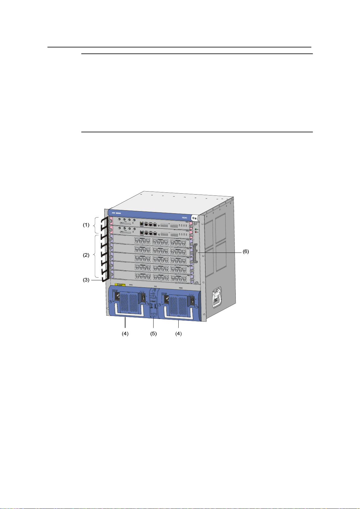
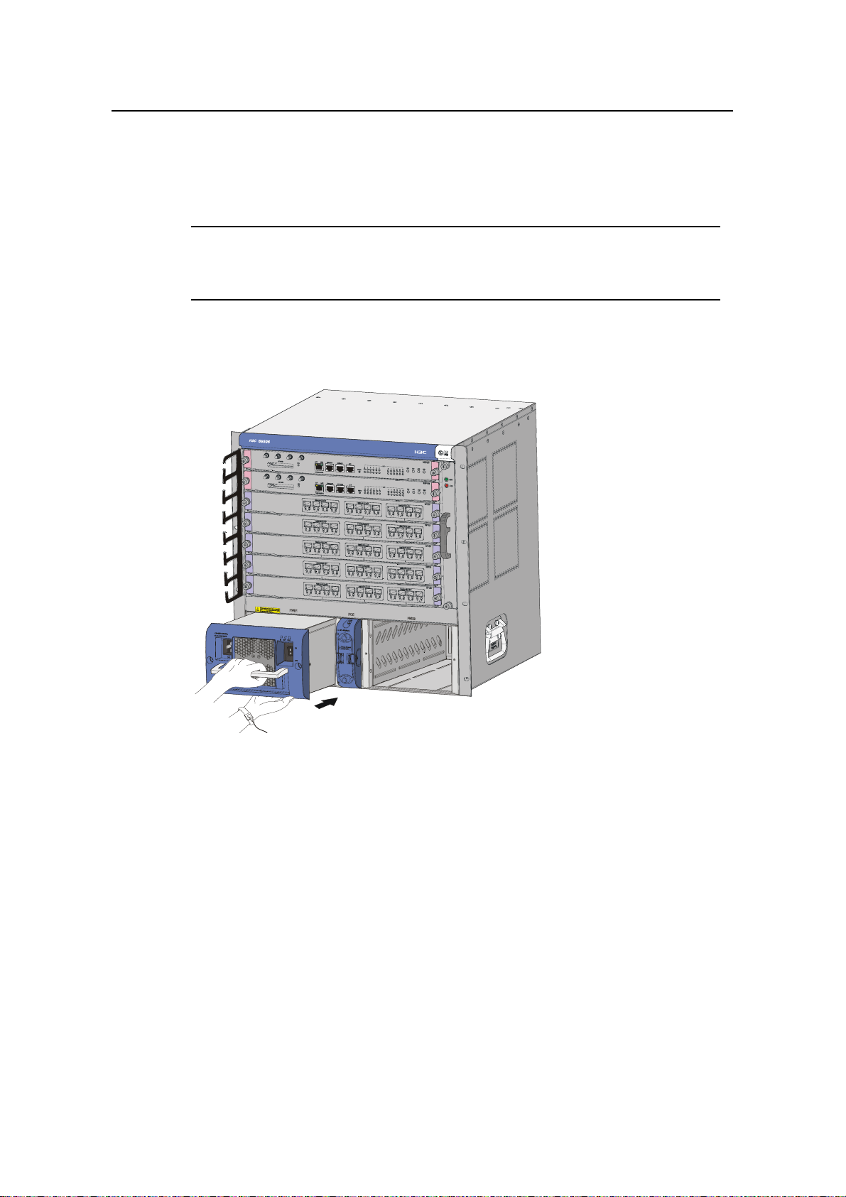
I. S9505
(1) SRPU slots (2) LPU slots (3) Cable management bracket
(4) PSUs (5) PoE power entry module (6) Fan tray
Figure 1-1 Front view of the S9505
z The S9505 chassis provides seven slots in its board area: The top two
accommodate SRPUs, which can operate in 1+1 re dundancy mode; the remaining
five accommodate LPUs/service boards.
z At the bottom of the chassis is the power area that contains one PoE entry module
and two PSUs. The two PSUs are hot-swappable; they can operate in 1+1
redundancy mode. The switch supports both A C and DC power inputs. So you can
select AC or DC PSUs as needed.
1-2
Page 9
Installation Manual
H3C S9500 Series Routing Switches Chapter 1 Product Overview
z On the right of the chassis is the fan area that contains one vertical fan tray. The
fans draw air in from the left and exhausts air from the right.
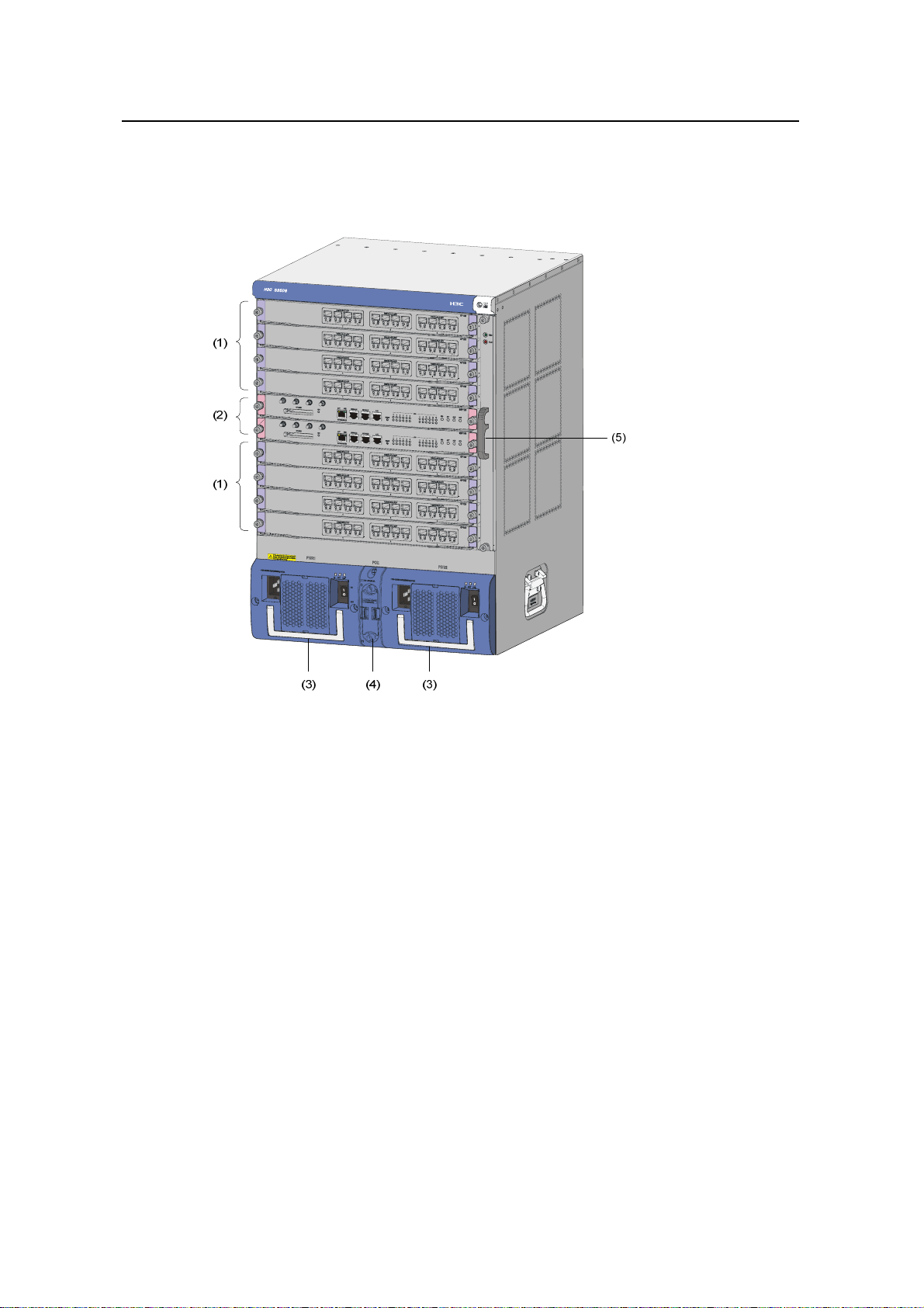
II. S9508
(1) LPU slots (2) SRPU slots (3) PSUs
(4) PoE power entry module (5) Fan tray
Figure 1-2 Front view of the S9508
z The S9508 chassis provides ten slots in its board area: The middle two
accommodate SRPU modules; the remaining eight accommodate LPUs/service
boards.
z At the bottom of the chassis is the power area that contains one PoE power entry
module and two PSUs. The switch supports both AC and DC power inputs. So you
can select AC or DC PSUs as needed.
z On the right of the chassis is the fan area that contains one vertical fan tray. The
fans draw air in from the left and exhausts air from the right.
1-3
Page 10
Installation Manual
H3C S9500 Series Routing Switches Chapter 1 Product Overview
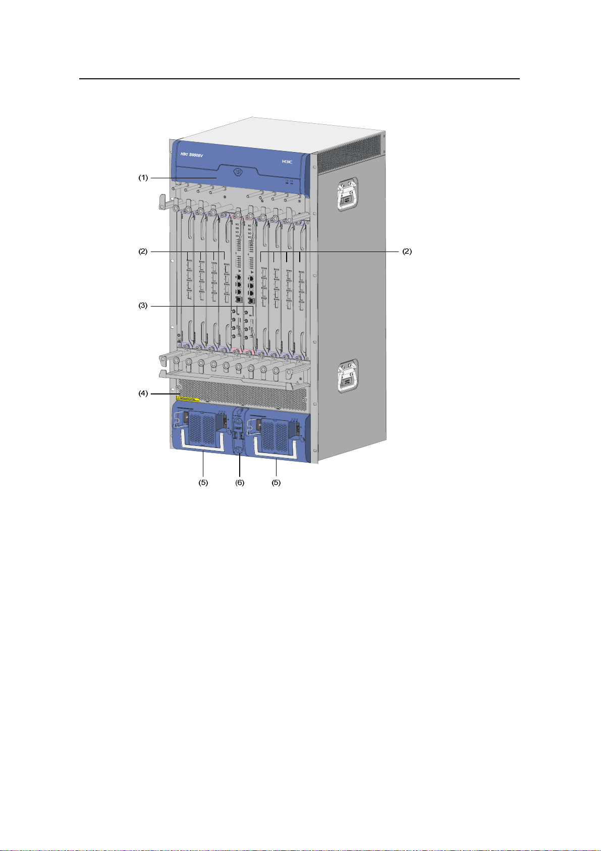
III. S9508V
(1) Fan tray (2) LPU slots (3) SRPU slots
(4) Air filter (5) PSUs (6) PoE power entry module
Figure 1-3 Front view of the S9508V
z The S9508V chassis provides ten vertical slots in its board area: The middle two
accommodate SRPU modules; the remaining eight accommodate LPU/service
boards.
z At the bottom of the chassis is the power area that contains one PoE power entry
module and two PSUs. The switch supports both AC and DC power inputs. So you
can select AC or DC PSUs as needed.
z Above the power area is the air filter, which can be removed from the chassis in
the case of replacement or regular cleaning.
z On the top of the chassis is the fan area that contains one horizontal fan tray. The
fans draw air in from the bottom and exhaust air from the top.
1-4
Page 11
Installation Manual
H3C S9500 Series Routing Switches Chapter 1 Product Overview
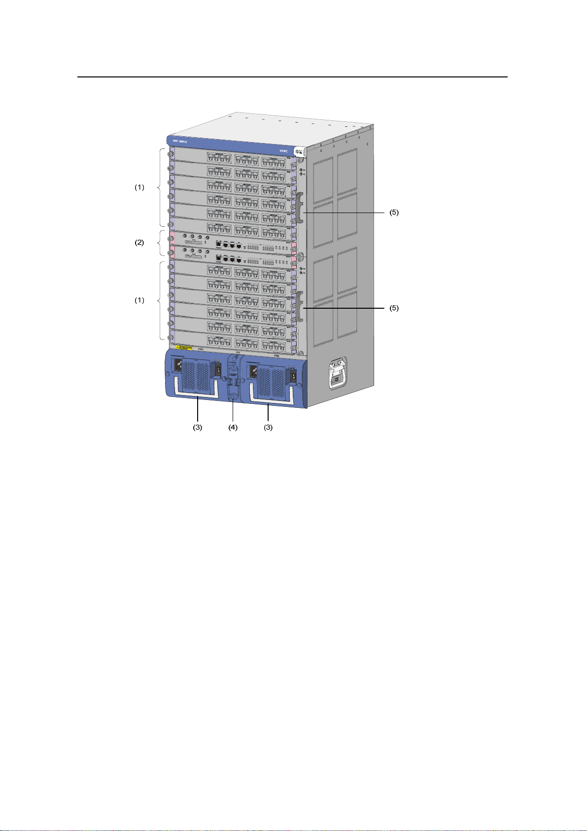
IV. S9512
(1) LPU slots (2) SRPU slots (3) PSUs
(4) PoE power entry module (5) Fan trays
Figure 1-4 Front view of the S9512
z The S9512 chassis provides fourteen slots in its board area: The middle two
accommodate SRPU modules and the remaining twelve accommodate
LPUs/service boards.
z At the bottom of the chassis is the power area that contains one PoE entry module
and two PSUs. The switch supports both AC and DC power inputs. So you can
select AC or DC PSUs as needed.
z On the right of the chassis is the fan area that contains two vertical fan trays. The
fans draw air in from the left and exhaust air from the right.
1.2.2 Backplane
The backplane of the S9500 series allows high-speed data exchange between SRPUs
and LPUs, as well as the exchange of various management and control signals in the
system.
1-5
Page 12

Installation Manual
H3C S9500 Series Routing Switches Chapter 1 Product Overview
I. Functions
The following are the main functions of the backplane:
z Providing communication channels for signal exchange between boards
z Supporting board hot-swapping
z Supporting board auto-discovery in slots
z Connecting PSUs to distribute power SRPUs, LPUs/service boards, and fan tray(s)
and providing monitor channels for them.
II. Structure
The S9500 series use a passive backplane, which provides multiple board slot s, one or
two fan interfaces, and two –48V power interfaces (one for PSUs and the other for PoE
power entry module).
1.2.3 Power System
Note:
z The S9500 series support both AC and DC power inputs. So you can choose A C or
DC PSUs as needed.
z The S9500 series support 1+1 power supply redundancy.
z The PSUs of the S9500 series are hot-swappable.
The power system is at the bottom of the chassis. In the PSU slot s, you can insert either
two AC PSUs or two DC PSUs. The PSUs are cooled by the built-in fans, which draw
air into the chassis from the front and exhaust air from the rear.
z AC PSU
Table 1-1 Specifications for AC PSUs
Specifications
Item
NEPS1200-A NEPS2000-A NEPS3500-A
Model S9505 S9508/S9512 S9508/S9512
Rated
voltage
range
100 to 240 VAC, 50
Hz or 60 Hz
100 to 120 VAC, 60 Hz
200 to 240 VAC, 50 Hz
100 to 240 VAC,
50 Hz or 60 Hz
Input
voltage
range
90 to 264 VAC, 50 Hz
or 60 Hz
90 to 264 VAC, 50 Hz or
60 Hz
1-6
90 to 264 VAC, 50
Hz or 60 Hz
Page 13

Installation Manual
H3C S9500 Series Routing Switches Chapter 1 Product Overview
Specifications
Item
NEPS1200-A NEPS2000-A NEPS3500-A
Max
input
15 A 15 A
current
Table 1-2 Configuration and output power of AC PSUs
PSU Configuration
NEPS1200-A
NEPS2000-A
1 × NEPS1200-A, no redundancy
2 × NEPS1200-A, 1+1 redundancy
1 × NEPS2000-A, no redundancy
2 × NEPS2000-A, 1+1 redundancy
1 × NEPS3500-A enclosure + 1 ×
sub-PSU, no redundancy
1 × NEPS3500-A enclosure + 2 ×
sub-PSU, 1+1 redundancy
1 × NEPS3500-A enclosure + 2 ×
sub-PSU, no redundancy
NEPS3500-A
2 × NEPS3500-A enclosure + 3 ×
sub-PSU, 2+1 redundancy
2 × NEPS3500-A enclosure + 4 ×
sub-PSU, 2+2 redundancy backup
Single 1800 W
sub-PSU :15 A
Two 1800W
sub-PSUs: 30 A
Maximum output
power
1200 W (90 V to 264 V)
1200 W (90 V to 160 V)
2000 W (160 V to 264 V)
1200 W (90 V to 180 V)
1800 W (180 V to 264 V)
2400 W (90 V to 180 V)
3500 W (180 V to 264 V)
2 × NEPS3500-A enclosure + 3 ×
sub-PSU, no redundancy
2 × NEPS3500-A enclosure + 4 ×
3500 W (90 V to 180 V)
sub-PSU, 3+1 redundancy
z DC PSU
Table 1-3 Specifications for DC PSUs
Specifications
Item
NEPS1200-D NEPS2000-D NEPS3500-D
Model S9505 S9508/S9512 S9508/S9512
Rated
voltage
–48 to –60 VDC –48 to –60 VDC –48 to –60 VDC
range
Input
voltage
–36 to –72 VDC –36 to –72 VDC –36 to –72 VDC
range
1-7
Page 14
Installation Manual
H3C S9500 Series Routing Switches Chapter 1 Product Overview
Specifications
Item
NEPS1200-D NEPS2000-D NEPS3500-D
Max
input
25 A 42 A 75 A
current
Max
output
1,200 W 2,000 W 3,500 W
power
1.2.4 PoE Power Supply
The S9500 series support power over Ethernet (PoE). With this feature, an S9500
switch equipped with an external PoE power supply and PoE-capa ble LPUs can deliver
–48 VDC to its remotely powered devices (PDs), such as IP phones, wireless LAN
(WLAN) access points (APs) and network cameras, through Ethern et cables.
Currently, among the LPUs of the S9500 series, only GV48 is PoE capabl e.
z The S9500 series can supply power to remote PDs through Ethernet electrical
ports on the LPUs. Each LPU can simultaneously supply power to up to 48 PDs
with the maximum distance of 100 m (328.1 feet).
z Each Ethernet port can deliver up to 15.4 W to its PD.
z The S9500 series determine whether to deliver power to a newly detected PD
according to the following condition: If the remaining PoE power of the switch is
greater than what is required by a newly detected PD, the switch supplies powe r to
it. Otherwise, the switch does not supply power to it.
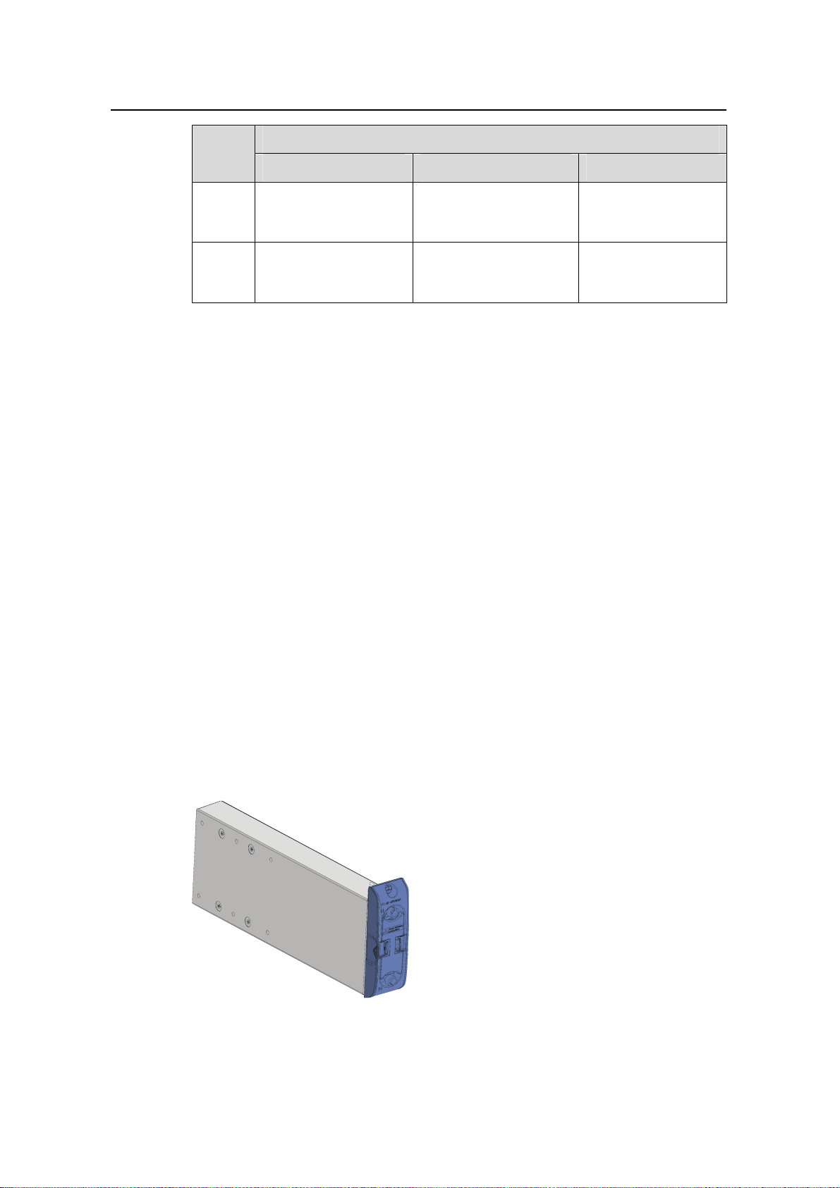
I. PoE power entry module
The PoE-supported S9505/S9508/S9508V/S9512 switch chassis has a PoE power
entry module between the two PSUs. You can co nnect this PoE power entry mo dule to
an external PoE power supply PSE4500-A.
Figure 1-5 PoE power entry module
1-8
Page 15
Installation Manual
H3C S9500 Series Routing Switches Chapter 1 Product Overview
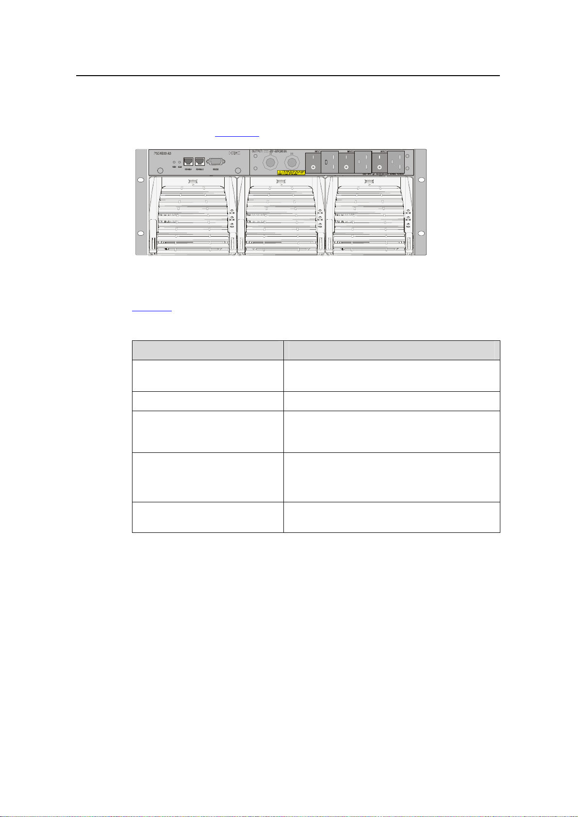
II. External PoE power supply
The S9505/S9508/S9508V/S9512 uses the PSE4500-A power system as an external
PoE power supply.
Figure 1-6 shows the PSE4500-A front panel.
Figure 1-6 PSE4500-A front panel
Table 1-4 describes typical equipment configurations and specifications of PSE4500-A.
Table 1-4 Typical equipment configurations and specifications of PSE4500-A
Item Specifications
Physical dimensions (H × W × D)
175 × 482.6 × 320.5 mm (6.89 × 19.00 × 12.62
in.)
System controller One
Two NP2500UACs (required) + one redundant
Rectifiers (NP2500UAC)
NP2500UAC (optional); NP2500UAC is
hot-swappable
Three AC inputs and switches
AC accessories
Three AC voltage detection circuits
Input voltage range: 90 to 264 VAC
DC accessories
A single DC output, with a max output power of
4500 W (220 V)/2400 W (110 V)
The external PoE power system has the monitoring function. It provides one RS232
and two RS485 monitoring interfaces. The external PoE power supply can display
alarm information through the ALM LED. The system can learn th e running information
of the rectifiers by connecting a monitoring port to the SRPU. You can use cables to
connect the monitoring ports from the front or the rear of the external PoE power
supply.
1-9
Page 16

Installation Manual
H3C S9500 Series Routing Switches Chapter 1 Product Overview
Note:
The external PoE power system for the S9500 series only support RS485 monitoring
ports.
Table 1-5 LEDs of external PoE power system
LED Label Color
Input power
LED
Output
power LED
Fault LED Fault Red OFF ON
Running
status LED
Alarm LED ALM Red OFF ON
1.2.5 Fan Tray
Normal
state
Abnormal
state
AC Green ON OFF
DC Green ON OFF
RUN Green ON OFF
Abnormal reason
Loss of AC input
power, or blown fuse
No DC output from
PSU
Irreversible fault
occurred in PSU
PSU shutdown or
PSU running trouble
Loss of AC input
power, under-voltage
or over-voltage input,
over-voltage output,
output short-circuit,
or PSU fault
z The S9505 uses one 25 W fan tray, which contains four 120 × 120 × 25.4 mm (4.7
× 4.7 × 1.0 in.) DC fan units.
z The S9508 uses one 35 W fan tray, which contains six 120 × 120 × 25.4 mm (4.7 ×
4.7 × 1.0 in.) DC fan units.
z The S9508V uses one 70 W fan tray, which contains six 120 × 1 20 × 38 mm (4.7 ×
4.7 × 1.5 in.) DC fan units.
z The S9512 uses two 25 W fan trays, each of which contains four 120 × 120 × 25.4
mm (4.7 × 4.7 × 1.0 in.) DC fan units.
The fans of the S9505/S9508/S9508V/S9512 operate at –48 VDC supplied from the
backplane.
1-10
Page 17
Installation Manual
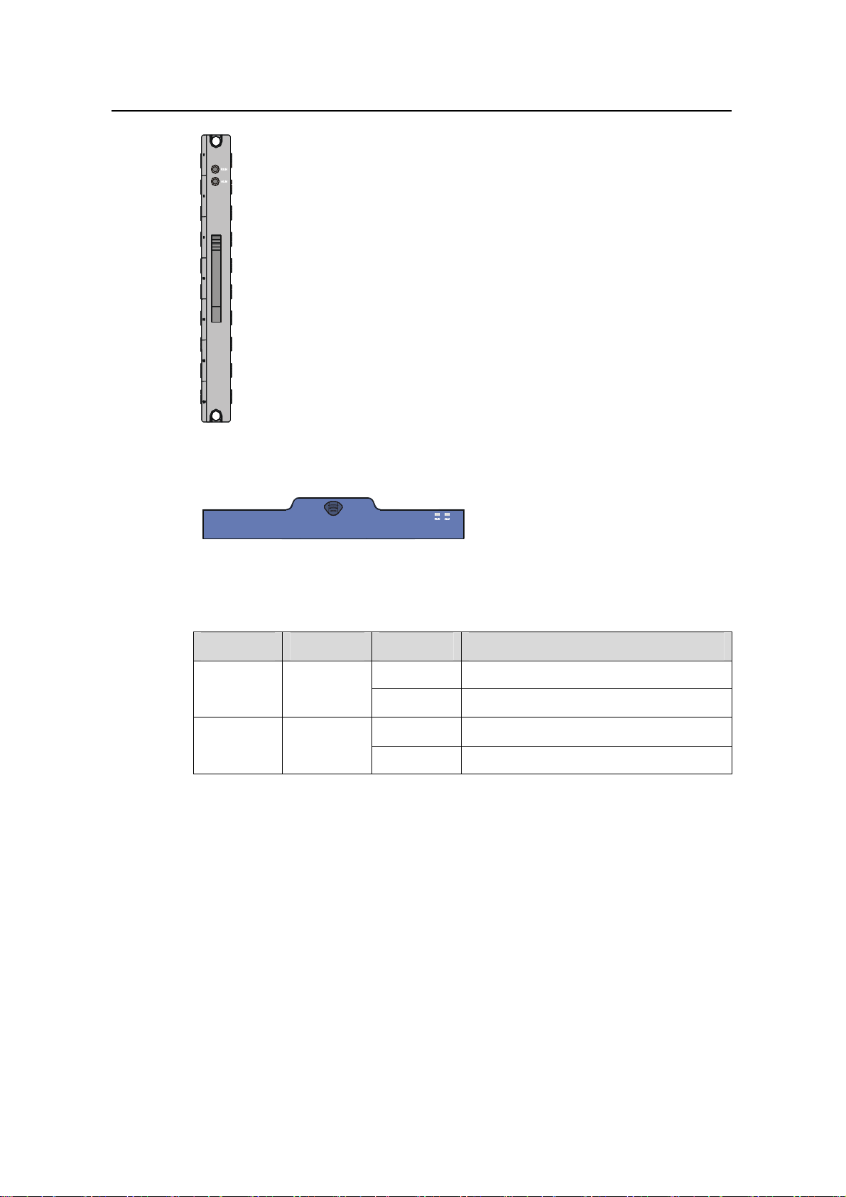
H3C S9500 Series Routing Switches Chapter 1 Product Overview
Figure 1-7 Fan tray panel of the S9505/S9508/S9512
Figure 1-8 Fan tray panel of the S9508V
Table 1-6 LEDs on fan tray panel
LED Color Status Meaning
OFF The fan tray is faulty.
RUN Green
ON The fan tray is operating normally.
OFF The fan tray is operating normally.
ALM Red
ON The fan tray is faulty.
1.3 Switching and Routing Processing Unit
SRPUs serve as the core of the S9500 series. They mainly have the following
functions:
z Route calculation and forwarding table maintenance.
z Integrating crossbar switching fabric to accomplish service exchange between
different boards.
z Providing system configuration and monitoring functions, which allows the syste m
to monitor other boards and upgrade/reset service board software.
The following table lists the SRPUs applicabl e to the S9500 series.
1-11
Page 18

Installation Manual
H3C S9500 Series Routing Switches Chapter 1 Product Overview
Table 1-7 SRPUs applicable to the S9500 series
SRPU S9505 S9508 S9508V S9512
LSB1SRP1N4
9
LSB1SRP1N5
LSB1SRP1N6
LSB1SRP1N7
LSB1SRP2N4
LSB1SRP2N5
LSB1SRP2N6
LSB1SRP2N7
LSB2SRP2N4
LSB2SRP2N5
LSB2SRP2N6
LSB2SRP2N7
Note:
The tick 9 indicates that the SRPU is applicable to the switch. SRP2N’s forwarding
capacity is twice the SRP1N’s.
9
9
9
9
9
9
9
9
9
9
9
9
9
9
9
9
9
9
9
9
9
9
9
1.4 Line Processing Unit
The following LPUs are available:
Table 1-8 LPUs available
LPU Suffix User interface
LSB1FP20 B0, CA0 20 × 100 Mbps SFP/LC optical ports
LSB1F32G B0, CA0
LSB1FT48 B0 48 × auto-sensing 10/100 Mbps RJ-45 electrical ports
LSB2FT48 CA0 48 × auto-sensing 10/100 Mbps electrical ports
LSB1GP12
LSB1GP24
B0, CA0,
DB0
B0, CA0,
CB0, DB0,
DC0
4 × 1000 Mbps SFP/LC optical ports and 32 ×
auto-sensing 10/100 Mbps RJ-45 ports
12 × 1000 Mbps SFP/LC optical ports
24 × 1000 Mbps SFP/LC optical ports
1-12
Page 19

Installation Manual
H3C S9500 Series Routing Switches Chapter 1 Product Overview
LPU Suffix User interface
LSB2GP24 DB0, DC0 24 × 1000 Mbps SFP/LC optical ports
LSB1GP48 DB0
48 × 1000 Mbps SFP/LC optical ports (1:4
convergence)
LSB1GP48L DB0 48 × 1000 Mbps SFP/LC optical ports (wire-speed)
LSB1GV48 DB0
LSB2GV48 DB0
LSB1GT24
B0, CA0,
DB0
LSB2GT24 DB0
LSB1GT48L DB0
LSB1P4G8 CA0
LSB1GT8P CA0
B0, CA0,
LSB1XP2
CB0, DB0,
DC0
48 × auto-sensing 10/100/1000 Mbps RJ-45
electrical ports (PoE-capable)
48 × auto-sensing 10/100/1000 Mbps RJ-45
electrical ports (PoE-capable)
24 × auto-sensing 10/100/1000 Mbps RJ-45
electrical ports
24 × auto-sensing 10/100/1000 Mbps RJ-45
electrical ports
48 × auto-sensing 10/100/1000 Mbps RJ-45
electrical ports (wire-speed)
8 × 1000 Mbps SFP/LC optical ports and 4 × OC-3c
SFP/LC POS optical ports
4 × 1000 Mbps SFP/LC optical ports and 8 ×
auto-sensing 10/100/1000 Mbps RJ-45 ports
2 × 10GBase-R XFP/LC/10GBase-W XFP/LC optical
ports
LSB1XP4
B0, CA0,
DB0
LSB1XP4L DB0
LSB1XP4T DB0
LSB1XK1
B0, CA0,
DB0
4 × 10GBase-R XFP/LC/10GBase-W XFP/LC optical
ports (1:2 convergence)
4 × 10GBase-R XFP/LC/10GBase-W XFP/LC optical
ports (wire-speed)
4 × 10GBase-R XFP/LC/10GBase-W XFP/LC optical
ports
1 × 10GBase-R XENPAK/SC port
LSB1SP4 CA0 4 × OC-48c SFP/LC POS optical ports
LSB1UP1 CA0 1 × OC-192c XFP/LC POS optical port
LSB1VP2 CA0 2 × OC-192c XFP/LC RPR optical ports
LSB1RSP2 CA0 2 × OC-48c SFP/LC RPR optical ports
1-13
Page 20

Installation Manual
H3C S9500 Series Routing Switches Chapter 1 Product Overview
Note:
The first column and the second column in the above table form an LPU model, for
example, LSB1XP2B0.
1.5 Service Board
Each kind of service board is specially designed for high-speed p rocessing of a cert ain
service and has partial or no functions of LPU.
Currently, the following service boards are available:
z LSB1NATB0: for NAT service, no service port
z LSB1VPNB0: for VPLS service, no service port
z LSB1NAMB0: for NAM service, no service port
Note:
For detailed specifications for the SRPUs, LPUs, and service boards, visit the website
at www. h3c.com.
1.6 System Specifications
The following table summarizes the physical specifications of the S9500 series.
Table 1-9 Technical specifications of the S9500 series
Item S9505 S9508 S9508V S9512
486 × 436 ×
Dimensions
(H × W × D)
Weight (full
load)
Max power
consumption
450 mm (19.1
× 17.2 × 17.7
in.)
≤ 65 kg (143
lb)
1,200 W 2,000 W 2,000 W
619 × 436 × 450
mm (24.4 × 17.2
× 17.7 in.)
≤ 80 kg (176 lb)
888 × 436 ×
450 mm (35 ×
17.2 × 17.7
in.)
≤ 90 kg
(198.4 lb)
753 × 436 × 450
mm (29.6 × 17.2
× 17.7 in.)
≤ 100 kg (220
lb)
2,000 W/3,500
W
Overall
switching
capacity
Number of
VLANs
SRP1N6:
300 Gbps
SRP2N6: 600
Gbps
4 K
SRP1N5:
480 Gbps
SRP2N5:
960 Gbps
1-14
SRP1N5:
480 Gbps
SRP2N5:
960 Gbps
SRP1N4:
720 Gbps
SRP2N4:
1.44 Tbps
Page 21

Installation Manual
H3C S9500 Series Routing Switches Chapter 1 Product Overview
Item S9505 S9508 S9508V S9512
Forwarding
table entries
Number of
SRPU slots
SRPU type
Number of
LPU slots
User interface
128 K/256 K/512 K
2 2 2 2
LSB1SRP1N
6
LSB1SRP1N
7
LSB1SRP2N
6
LSB1SRP2N
7
LSB1SRP1N5
LSB1SRP1N7
LSB1SRP2N5
LSB1SRP2N7
LSB1SRP1N
5
LSB1SRP1N
7
LSB1SRP2N
5
LSB1SRP2N
7
LSB1SRP1N4
LSB1SRP1N7
LSB1SRP2N4
LSB1SRP2N7
5 8 8 12
z 10/100/1000BASE-TX RJ45
z 10/100BASE-TX RJ45
z 1000BASE-X-SFP/LC
z 100BASE-FX SFP/LC
z 10GBASE-R XENPAK/SC
z 10GBASE-R/W XFP/LC
z OC-3c SFP/LC POS
z OC-48c SFP/LC POS
z OC-192c SFP/LC POS
z OC-48c SFP/LC RPR
z OC-192c SFP/LC RPR
Operating temperature
Operating humidity
(noncondensing)
Storage temperature
0°C to 45°C (32°F to 113°F)
10% to 90%
–40°C to 70°C (–40°F to 158°F)
Storage humidity 5% to 95%
1-15
Page 22

Installation Manual
H3C S9500 Series Routing Switches Table of Contents
Table of Contents
Chapter 2 Preparing for Installation............................................................................................2-1
2.1 Safety Recommendations.................................................................................................. 2-1
2.1.1 General Safety Recommendations.........................................................................2-1
2.1.2 Electrical Safety.......................................................................................................2-1
2.1.3 ESD Damage Prevention........................................................................................ 2-1
2.1.4 Handling Safety.......................................................................................................2-2
2.1.5 Laser Safety............................................................................................................2-2
2.2 Examining Installation Site................................................................................................. 2-3
2.2.1 Temperature Requirements....................................................................................2-3
2.2.2 Humidity Requirements...........................................................................................2-3
2.2.3 Cleanness Requirements........................................................................................2-4
2.2.4 EMS Requirements................................................................................................. 2-5
2.2.5 Grounding Requirements........................................................................................2-5
2.2.6 Power Supply Requirements...................................................................................2-5
2.2.7 Space Requirements............................................................................................... 2-6
2.3 Cabinet-Mounting Requirements.......................................................................................2-7
2.3.1 Cabinet Requirements ............................................................................................ 2-7
2.3.2 Requirements of Supports ...................................................................................... 2-8
2.4 Requirements of Power Distribution Box...........................................................................2-9
2.4.1 Installing the AC Power Distribution Box ................................................................2-9
2.4.2 Installing DC Power Distribution Box....................................................................2-12
2.5 Installation Tools.............................................................................................................. 2-16
i
Page 23

Installation Manual
H3C S9500 Series Routing Switches Chapter 2 Preparing for Installation
Chapter 2 Preparing for Installation
2.1 Safety Recommendations
T o avoid po ssible bodily injury and equipment damage, please read the following safety
recommendations carefully before installing the S9500 series. The recommendations
do not cover every possible hazardous condition.
2.1.1 General Safety Recommendations
z Take necessary safety measures to avoid injury and device damage. For example,
wear an ESD-preventive wrist strap.
z Make sure that the ground is dry and flat and you have adopted anti-slip
measures.
z Keep the chassis clean and dust-free. Do not place the switch on a moist area and
avoid liquid flowing into the switch.
z Keep the chassis and installation tools away from walk areas.
2.1.2 Electrical Safety
z Look carefully for possible hazards in your work area, such as un grou nde d power
extension cables, missing safety grounds, and moist floors.
z Locate the emergency power-off switch in the room before installation. Shut the
power off at once in case accident occurs.
z Unplug all the external cables (including power cords) before moving the chassis.
z Better not maintain the equipment alone when it has been powered.
z Never assume but check each time that power has been disconnected from a
circuit.
2.1.3 ESD Damage Prevention
To prevent the electronic components from being damaged by the electrostatic
discharge (ESD), you should not only take ESD measures where the switch is located,
but also take the following precautions:
z Always wear an ESD-preventive wrist strap when installing components,
especially the electronic printed circuit boards.
z Hold the edges of the PCB when necessary. Do not touch any electronic
components or printed circuit.
Take the following steps to use the ESD-preventive wrist strap.
1) Wear the wrist strap on your wrist.
2) Lock the wrist strap tight around your wrist to keep good contact with the skin.
2-1
Page 24
Installation Manual
H3C S9500 Series Routing Switches Chapter 2 Preparing for Installation
3) Insert the ESD-preventive wrist strap into the specially designed hole on the
switch chassis or attach it to the grounding screw of the chassis th e alligator clips.
4) Make sure that the ESD-preventive wrist strap is well grounded.
Caution:
For the sake of safety, check the resistance of the ESD-preventive wrist strap. The
resistance reading should be in the range of 1M to 10 M ohm between human body and
the ground.
2.1.4 Handling Safety
Since the S9500 series are rather large and heavy, you should follow the
recommendations below:
z Remove all the external cables (including power cords) before moving the chassi s.
z Do not move the switch alone.
z Move the switch slowly and stably. Keep in step with your partner and balance
your bodies when moving the switch.
Caution:
You can only hold the handles at both sides of the chassis when mov ing the switch, but
not the plastic panel of the chassis, the handle of the fan frame, the handle of the PSUs,
the handle of the back cover of the chassis, or the air vents of chassis.
Any attempt to carry the switch with these parts may cause equipment damage or even
bodily injury.
2.1.5 Laser Safety
S9500 series routing switches are class 1 laser products.
When an optional optical interface board of an S9500 switch is operating, do not stare
into the open optical port because the laser emitted from it has very high power density
and is harmful to your retina.
2-2
Page 25
Installation Manual
H3C S9500 Series Routing Switches Chapter 2 Preparing for Installation
Caution:
The laser inside the optical fibre may hurt your eyes.
2.2 Examining Installation Site
The S9500 series can only be used indoors. To ensure that the switch works normally
and to prolong its service lifetime, the following requirement s shoul d be met in terms of
installation environment.
2.2.1 Temperature Requirements
To ensure the normal operation of a switch, the temperature in the room should be
maintained within a proper range.
Table 2-1 Temperature requirements
Table 2-1 describes temperatu re requirements.
Temperature Range
Operating temperature 0°C to 45°C (32°F to 113°F)
Storage temperature –40°C to +70°C (–40°F to 158°F)
The higher the temperature, the greater the damage it will do to the switch. Long-lasting
high temperature will speed up the aging process of the insulating materials, greatly
lower the reliability of the switch, and therefore affect its service life seriously.
Caution:
After the switch is moved to a high-temperature location, if condensate appears on the
switch, you must dry the switch before power-on, thus to avoid damaging interior
components due to short circuit.
2.2.2 Humidity Requirements
To ensure the normal operation of a switch, the humidity in the equipm ent room should
be maintained within a proper range.
Table 2-2 describes humidity req uirements.
2-3
Page 26
Installation Manual
H3C S9500 Series Routing Switches Chapter 2 Preparing for Installation
Table 2-2 Humidity requirements
Humidity Range
Operating humidity (noncondensing) 10% to 90%
Storage humidity (noncondensing) 5% to 95%
Long-lasting high humidity in the equipment room is prone to poor insulation or even
leakage of the insulating material. Sometimes, the mechanical performance
deterioration, the rustiness and corrosion of some metal parts are also more likely to
occur.
If the relative humidity is too low, the captive screws may become loose due to the
insulation washer contraction. Meanwhile, the electrostatic is likely to be produced in
the dry environment, which will jeopardize the CMOS circuit of the switch.
2.2.3 Cleanness Requirements
Dust is a hazard to the operating safety of the switch. The indoor dust accum ula ted on
the chassis can cause electrostatic adsorption, whi c h may result in the poor contact of
the connector or metal contact point. This happens more frequently when indoor
relative humidity is low, which will not onl y shorten the service life of the switch, but also
cause communication failure.
The required specifications on dust content and particle diameter in an equipment room
are shown in the following table.
Table 2-3 Limitation on dust content and particle diameter in the equipment room
Mechanical active material Content limit (particles/m³)
4
Dust particle
≤ 3 x 10
(No visible dust on desk in three days)
Note: Dust particle diameter ≥ 5 µm
Besides the dust specifications, the equipment room of the switch should al so meet the
rigorous requirements for the content of salt, acid and sulfide in the air. These harmful
gases could accelerate the metal erosion and the aging process of some parts.
Incursion of harmful gases, su ch as SO
, H2S, NO2, NH3, and Cl2, should be prevented.
2
The specific limitation values of these harmful gases are given in the following table.
Table 2-4 Harmful gas limits in an equipment room
Gas Average (mg/m³) Max. (mg/m³)
SO2 0.3 1.0
H2S 0.1 0.5
2-4
Page 27

Installation Manual
H3C S9500 Series Routing Switches Chapter 2 Preparing for Installation
Gas Average (mg/m³) Max. (mg/m³)
NO2 0.004 0.15
NH
Cl
3
2
1.0 3
0.1 0.3
2.2.4 EMS Requirements
Any possible interference sources, no matter whether outside or inside the system,
affect the switch in use through capacitive coupling, inductive coupling,
electromagnetic radiation, common impedance (including the grounding system)
coupling or conducting line (power line, signalling line and transmission line etc). To
prevent the interference, you should:
z Take effective measures against electrical net interference for power supply
system.
z Separate the working ground of the switch from the grounding device of the power
supply equipment or lightning-protection grounding device as far as possible.
z Keep the switch far away from the radio launcher, radar launcher, and
high-frequency devices working in the high current.
z Adopt electromagnetic shielding if necessary.
Note:
If necessary, take electromagnetic shielding measures against the interference.
2.2.5 Grounding Requirements
A good groun ding system is not only the basis essential to the stable and reliable swit ch
operation, but also an important guarantee of lightning protection, anti-interference a nd
ESD-prevention. The user must provide good grounding system for the switch. The
resistance between the chassis and the ground must be less than 1 ohm.
2.2.6 Power Supply Requirements
The following tables describe the specifications for AC and DC PSUs.
2-5
Page 28

Installation Manual
H3C S9500 Series Routing Switches Chapter 2 Preparing for Installation
Table 2-5 Specifications for AC PSUs
Item
Specifications
NEPS1200-A NEPS2000-A NEPS3500-A
Model S9505 S9508/S9512 S9508/S9512
Rated
voltage
range
Input
voltage
range
Max
input
current
100 to 240 VAC, 50
Hz or 60 Hz
90 to 264 VAC, 50 Hz
or 60 Hz
15 A 15 A
100 to 120 VAC, 60 Hz
200 to 240 VAC, 50 Hz
90 to 264 VAC, 50 Hz or
60 Hz
100 to 240 VAC,
50 Hz or 60 Hz
90 to 264 VAC, 50
Hz or 60 Hz
Single 1800W
sub-PSU:15 A
Two 1800W
sub-PSUs: 30 A
Table 2-6 Specifications for DC PSUs
Specifications
Item
NEPS1200-D NEPS2000-D NEPS3500-D
Model S9505 S9508/S9512 S9508/S9512
Rated
voltage
–48 VDC to –60 VDC –48 VDC to –60 VDC –48 VDC to –60 VDC
range
Input
voltage
–36 VDC to –72 VDC –36 VDC to –72 VDC –36 VDC to –72 VDC
range
Max
input
25 A 42 A 75 A
current
Max
output
1,200 W 2,000 W 3,500 W
power
2.2.7 Space Requirements
For the sake of adequate ventilation and easy equipment maintenance, you are
recommended to keep one meter of clearance between the rear/front of the switch
cabinet and the wall surface or other devices. If the optional cabinet is desired, the clea r
height of the equipment room must be more than 3 meters inclusive.
2-6
Page 29

Installation Manual
H3C S9500 Series Routing Switches Chapter 2 Preparing for Installation
2.3 Cabinet-Mounting Requirements
Before mounting the switch in a cabinet, make sure that the cabinet meet s the following
requirements.
2.3.1 Cabinet Requirements
I. Dimensions
A standard 19-inch cabinet is required.
You can install the switch in an N68 cabi net develope d by H3C. There a re two types of
N68 cabinets available for the S9500 series:
z N68-18 model: 1.8-meter-high N68 cabinet (600 × 800 × 1800 mm, or 23.6 × 31.5
× 70.9 in.)
z N68-22 model: 2.2-meter-high N68 cabinet (600 × 800 × 2200 mm or 23.6 × 31.5 ×
86.7 in.)
Note:
For the procedure of installing and remodeling an N68 cabinet, refer to H3C N68
Cabinet Installation and Remodel Introduction.
You can also install the swit ch in a 19-in ch cabin et provided by oth er vend ors.
II. Weight bearing capacity and power
The cabinet must be able to bear the weight of the switch and its accessories. A 20%
power margin should be reserved.
III. Grounding requirements
You must provide a good grounding system for the switch. The cabinet must be
equipped with a grounding terminal, as shown in
Figure 2-1.
2-7
Page 30
Installation Manual
H3C S9500 Series Routing Switches Chapter 2 Preparing for Installation
(1) Grounding cable (2) Grounding terminal
Figure 2-1 Ground the cabinet
IV. Heat dissipation
Air enters from the left of the S9500 series and exhausts from the right. Therefore, a
clearance of at least 15.2 cm (6.0 in.) is required between the side panels of the cabinet
and the switch. If the switch is to be installed in a closed cabinet, make sure that the
cabinet has a good ventilation system.
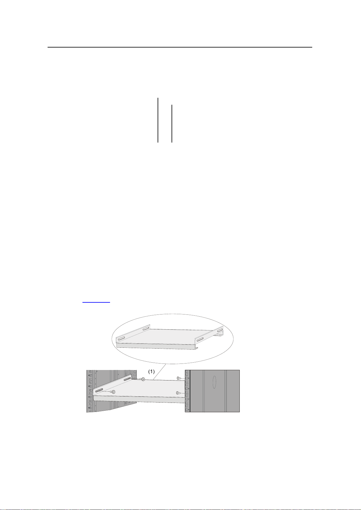
2.3.2 Requirements of Supports
1) The length of supports depends on the cabinet depth.
2) You can use supports such as shelf or angles to install the switch into the cabinet.
The supports must be able to bear the weight of the switch and its accessories.
Figure 2-2 shows a shelf.
(2)(1) (2)(1)
(1) Shelf
Figure 2-2 Shelf
2-8
Page 31

Installation Manual
H3C S9500 Series Routing Switches Chapter 2 Preparing for Installation
Figure 2-3 shows an angle support.
(1) Angle support
Figure 2-3 Angle support
2.4 Requirements of Power Distribution Box
You can install a power distribution box in the cabi net as required.
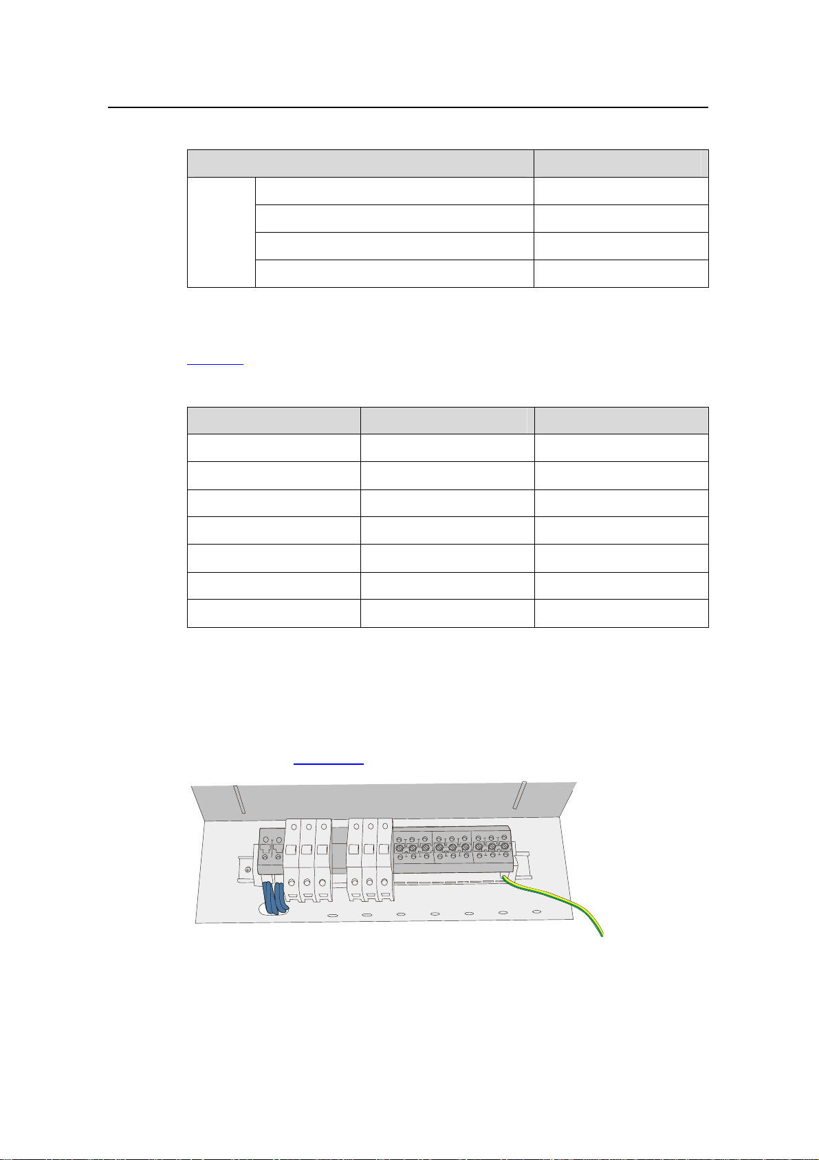
2.4.1 Installing the AC Power Distribution Box
I. Terminal Block
The terminal block is set on the bottom of a power distribution box.
Figure 2-4 Terminal block structure diagram
The terminal block has 21 terminals to connect power cords: seven grey terminals,
seven blue terminals and seven yellow-green terminals.
z The grey terminals from L1 to L7 are output ports for live wire. These ports are
connected to each other.
z The blue terminals from N1 to N7 are output ports for neutral wire. These ports are
connected to each other.
z The yellow-green terminals from PE1 to PE7 are output ports for earth wire. These
ports are connected to each other and connected to the cabinet.
2-9
Page 32

Installation Manual
H3C S9500 Series Routing Switches Chapter 2 Preparing for Installation
Table 2-7 Electrical specifications of the terminal block
Item Specification
Rated current 76A
Input
Rated voltage 1000V
Rated cross-sectional area 16 mm2
Maximum current/maximum crimping area 101A/25 mm
Output seven loop outputs
II. Power Distribution Box Appearance
Figure 2-5 Front view of the power distribution box
2
Figure 2-6 Top view of the power distribution box
Caution:
Make sure the power cord ports are covered with protection tube such that no wire
tailpiece is exposed at any joint.
III. Connect power cords to the power distribution box
2-10
Page 33

Installation Manual
H3C S9500 Series Routing Switches Chapter 2 Preparing for Installation
Caution:
The power distribution box takes AC high voltage. Do not operate it before breaki ng its
power.
1) Use three cables to connect the client power distribution box to the terminal block
of the cabinet power distribution box. You are recommended to use the cables
2
with 16 mm
cross-sectional area (the colors of the cables differ depending on the
cable specifications in different countries). Connect the power cords according to
the following relations:
z Live wire L in the client power distribution box — Live wire L in the cabinet power
distribution box
z Neutral wire N in the client power distribution box — Neutral wire N in the cabinet
power distribution box
z Earth wire G in the client power distribution box — Earth wire PE in the cabinet
power distribution box
2) Use 3.5 m (11.5 ft) long cables to connect the cabinet power distribution box to the
system power supply and PoE power supply. The three wires of ea ch cable should
be respectively connected to the ports L, N and PE of the power distribution box.
Make sure the protection tubes are used and no wire tailpiece is exposed during
the connection. You should connect power cord 1 to L1, N1 and PE1, power cord 2
to L2, N2 and PE2, and so on. The number of power cords d epends on the cabinet
configuration. Note that you should connect the brown wire to L (live wire), the blue
wire to N (neutral wire), and yellow-green wire to PE (earth wire).
3) After finishing the connection of the cables, bind these cables in order with cable
strap, wire them along the right side of the cabinet down, and connect them to the
input ports of the system power supply and PoE power supply. You should make
sure the cables are not loose.
IV. Installing the power distribution box
You should install the power distrib ution box on the top of the back of the N68 cabinet.
You can adjust the location of the box in a little range.
Figure 2-7 describes the cable connections on the cabinet power distribution box.
2-11
Page 34

Installation Manual
H3C S9500 Series Routing Switches Chapter 2 Preparing for Installation
(1) User-supplied
power distribution box
(5) PoE power entry
module
(9) External PoE
power supply
(19) Terminal block
(2) Guide rail
(6) S9505
chassis
(10) PoE AC
socket
Figure 2-7 Cable connections on the power distribution box
2.4.2 Installing DC Power Distribution Box
I. Terminal Block
1) Terminal block structure diagram
(3) Power distribution
box of the cabinet
(7) System power input
(11)~(17) No.1 to No.7
power cable
(4) S9505 chassis
(8) Interface area on
external PoE power
supply panel
(18) N68 cabinet
2-12
Page 35

Installation Manual
H3C S9500 Series Routing Switches Chapter 2 Preparing for Installation
BGND
BGND
BGND
BGND
BGND
BGND
PGND
PGND
PGND
(1) Air switch 1 (2) Air switch 2 (3) Guide rails
(4) PGND wiring terminal block (5) BGND wiring terminal block (6) Isolator
(7) Input terminal block
Figure 2-8 Terminal block structure
As illustrated in
Figure 2-8, the two leftmost input terminal blocks are DC input terminal
blocks. Next to them are two air switches, each of which has a through-current capacity
of 63A. On the rightmost side are 9 terminal blocks, 6 of which are BGND terminal
blocks and the rest are PGND terminal blocks.
2) Diagram for connecting terminal blocks
(1) Connected to user-supplied DC power
(3) Connected to the positive terminal of –48
V DC power
(2) Connected to the negative terminal of –48
V DC power
(4) Grounded and connected to the cabinet
Figure 2-9 Diagram for connecting DC input terminal blocks
3) Electrical performance of the terminal blocks
2-13
Page 36
Installation Manual
H3C S9500 Series Routing Switches Chapter 2 Preparing for Installation
Table 2-8 Electrical performance of the terminal block
Item Specification
Rated current 63 A
Input
Rated voltage 600 V
Rated cross-sectional area 16 mm2
2
Maximum current/maximum crimping area 63A/16 mm
4) Terminal block components
Table 2-9 illustrates terminal block components.
Table 2-9 Terminal block components
NO Name Quantity
1 End bracket 2
2 Cross connector 3
3 Marker 6
4 Terminal 11
5 Clapboard 7
6 Rail 1
7 Circuit breaker 6
II. Installing DC Power Distribution Box
To install power distribution box, take the following steps:
1) Install the DC input terminal blocks and air switches to the cabinet via the rail, as
illustrated in
Figure 2-10.
Figure 2-10 Install the DC input terminal blocks and air switches
2-14
Page 37

Installation Manual
H3C S9500 Series Routing Switches Chapter 2 Preparing for Installation
2) Connect the DC input terminal blocks and the air switches with 6 mm2 cables and
2
fix the cable properly. Also use a 6 mm
cable for grounding, as illustrated in
Figure 2-11.
Figure 2-11 Backplane diagram for connecting DC input terminal blocks and air
switches
3) Fix the DC power distribution box onto the back of the cabinet.
Figure 2-12 Diagram for fixing the power distribution box to the rear of the N68 cabinet
4) You can make the air switches to supply power to DC power modules by
connecting the lower terminals of the air switches to DC power input terminal s and
supply voltages to DC power. (Refer to
diameters of the cables need to be 6 mm
Figure 2-9 for detail. Note that the
2
or 10 mm2.)
5) You can use the BGND and PGND terminal blocks as needed. The rightmost
2
PGND terminals must be connected to the cabinet using 6 mm
illustrated in
Figure 2-12.
cables, as
6) Fasten the connected power cables with a wire and secure them onto the power
distribution box.
2
7) Use two 16 mm
cables to connect the cabinet and the DC power distribution box.
You need to connect the two cables to the leftmost terminal blocks of the cabinet,
as illustrated in
Figure 2-9.
2-15
Page 38

Installation Manual
H3C S9500 Series Routing Switches Chapter 2 Preparing for Installation
2.5 Installation Tools
Table 2-10 Required installation tools
Measure
and
lineation
tools
Long tape, ruler (1 meter in length), gradienter, marking
pen, powder marker, pencil
General
tools
Drills
Fastening
tools
Small tools
Auxiliary
tools
Special tools
Meters
One percussion drill, several drill bits, one vacuum
cleaner
Plain screwdriver P4 - 75 mm
Cross-head screwdriver P1 – 100 mm, P2 – 150 mm
and P3 – 250 mm
Box wrench M5
Ring spanner M6
Double ring spanner (10-12) or open ended spanner
(10-12)
Sharp-nose pliers, diagonal pliers, vices, hand-held
electric drill, file, handsaw, crowbar, rubber hammer
Brush, tweezers, paper knife, hand bellows, electric
iron, solder wire, fork, ladder
ESD-preventive wrist strap, cable stripper, crimping
pliers, RJ-45 crimping pliers, wire punch-down tool
Multimeter, 500 V Meg-ohmmeter (used for measuring
the insulation resistance), error detector, optical power
meter, earth resistance tester
Note:
The instruments and tools are not shipped with the S9500 serie s. Therefore, you need
to prepare the required instruments and tools.
2-16
Page 39

Installation Manual
H3C S9500 Series Routing Switches Table of Contents
Table of Contents
Chapter 3 Installing the Switch .......................................................................... 3-1
3.1 Installa tion Flow....................................................................................... 3-1
3.2 Confirming Installatio n Preparation ........................................................... 3-1
3.3 Mountin g the Swi tch in a Rac k.................................................................. 3-2
3.3.1 Prepar ations ................................................................................... 3-2
3.3.2 Installing the Cable Management Bracket and Rack-Mounting Ears .. 3-2
3.3.3 Mountin g the Switch ........................................................................ 3-3
3.3.4 Verify ing the Inst allation.................................................................. 3-3
3.4 Install ing the Switc h on a Workbench........................................................ 3- 4
3.4.1 Prepar ations ................................................................................... 3-4
3.4.2 Procedur e ....................................................................................... 3-4
3.5 Connecting the PGND Wire ...................................................................... 3-4
3.5.1 In a com mon grounding environment ............................................... 3-5
3.5.2 In ot her Groun ding Envir onments .................................................... 3-5
3.6 Installin g a PSU ....................................................................................... 3-9
3.6.1 Installation P reparation ................................................................... 3-9
3.6.2 Installation P rocedure ..................................................................... 3-9
3.6.3 Conne cting Power Cable(s) ............................................................ 3-11
3.7 Installin g a Board....................................................................................3-15
3.7.1 Installa tion Prepar ations ................................................................3-15
3.7.2 Installation P rocedure .................................................................... 3-16
3.8 Installin g PoE Power Supply .................................................................... 3-16
3.8.1 Installation P rocedure .................................................................... 3-17
3.8.2 Instal ling the PoE P ower Entry Mod ule ........................................... 3-17
3.8.3 Connec ting PoE Power Cables ....................................................... 3-18
3.9 Connecting Inter face Cables.................................................................... 3-20
3.9.1 Cable Routing R ecommenda tions ................................................... 3-20
3.9.2 Connectin g Console Cable ............................................................. 3-21
3.9.3 Connec ting the AUX Cable............................................................. 3-23
3.9.4 Conne cting Netw ork Cables ...........................................................3-23
3.9.5 Conne cting Fiber ...........................................................................3-23
3.10 Verifyi ng the Insta llation........................................................................3-27
i
Page 40

Installation Manual
H3C S9500 Series Routing Switches Chapter 3 Installing the Switch
Chapter 3 Installing the Switch
The S9500 series are designed for indoor applications.
Warning:
Do not touch any exposed wires, terminals or any parts labelled with a
high-voltage hazard warning to avoid bodily injury.
3.1 Installation Flow
Mount the switch in a rack
Start
Confirm installation preparation
Confirm installation position
Connect the PGND wire
Install a PSU
Install boards
Install PoE power supply
(optional)
Connect interface cables
Verify the installation
Finish
Install the switch on a workbench
Figure 3-1 Installation flow
3.2 Confirming Installation Preparation
z Make sure that you have read Chapter 2 Preparing for the Installation
carefully.
3-1
Page 41

Installation Manual
H3C S9500 Series Routing Switches Chapter 3 Installing the Switch
z All requirements mentioned in Chapter 2 Preparing for the Installation
have been met.
3.3 Mounting the Switch in a Rack
3.3.1 Preparations
Before installation, make sure that:
z The cabinet is grounded and stable. The layout inside the cabinet for
switch installation has been well done and there is no obstacle inside
or around the cabinet.
z The switch is ready for installation and has been carried to a place
near the cabinet.
3.3.2 Installing the Cable Management Bracket and Rack-Mounting Ears
For your convenience, a cable management bracket is shipped with the
S9500 series. Take the following steps to install the cable management
bracket.
1) Facing the LPU slots of the switch, insert the shipped cable
management bracket into the left rack-mounting ear on which there is
a recessed hole for installing the cable managem ent b racket, a nd fix it
with screws. (One cable management bracket for the
S9505/S9508/S9508V and two for the S9512).
2) Install the rack-mounting ears onto the both sides of the switch, as
shown in
Figure 3-2.
Figure 3-2 Install the cable management bracket and rack-mounting ears
3-2
Page 42

Installation Manual
H3C S9500 Series Routing Switches Chapter 3 Installing the Switch
3.3.3 Mounting the Switch
Note:
Make sure that supports have been installed in corresponding positions
and the supports can bear the switch weight.
1) Two people are required to lift the switch. Put the switch on the
supports and slide it into the cabinet until the rack-mounting ears
touch against the front square-holed columns.
2) Fix the rack mounting ears onto the square-holed columns with
screws.
Figure 3-3 Install the switch into a standard 19-inch rack
3.3.4 Verifying the Installation
After installing the switch into t he rack, check the items li st ed in Table 3-1.
Table 3-1 Checklist for switch installation
Item
The cable management bracket is well fixed
on the left rack-mounting ear.
Result
Remarks
Yes No
3-3
Page 43

Installation Manual
H3C S9500 Series Routing Switches Chapter 3 Installing the Switch
Item
Result
Remarks
Yes No
The rack-mounting ears are well fixed on the
switch.
The installation position is right.
The rack-mounting ears are well fixed on the
rack
3.4 Installing the Switch on a Workbench
When no 19-inch cabinet is available, you can place the switch on a clean
and stable workbench.
3.4.1 Preparations
z Make sure that the workbench is sturdy enough to bear the weight of
the switch and cables.
z Make sure that the workbench is flat and well grounded.
3.4.2 Procedure
Lift the switch onto the workbench with another person.
Caution:
Reserve at least 15.2 cm (6.0 in.) of clearance around the switch for heat
dissipation.
3.5 Connecting the PGND Wire
Caution:
For the safety of operators and equipment, the switch must be well
grounded. The resistance reading between switch chassis and the ground
must be less than 1 ohm.
3-4
Page 44

Installation Manual
H3C S9500 Series Routing Switches Chapter 3 Installing the Switch
3.5.1 In a common grounding environment
Follow these steps to connect the PGND wire in a common grounding
environment:
1) Remove the screw from the grounding hole in the switch chassis.
2) Wear the connector of the PGND wire accompanied with the switch on
the grounding screw.
3) Insert the grounding screw into the grounding hole and screw it down.
4) Connect the other end of the PGND wire to the groun d bar of the switch,
as shown in
Figure 3-4.
Figure 3-4 Connect the PGND wire
Note:
Generally, the cabinets installed in equipment rooms are equipped with
ground bar. In this case, you can connect the PGND wire of the switch to
the ground bar for it.
3.5.2 In other Grounding Environments
The following are some methods for grounding the switch in different
grounding environments.
3-5
Page 45

Installation Manual
H3C S9500 Series Routing Switches Chapter 3 Installing the Switch
Note:
Rather than specifying the switch model or sh owing the actual loca tion of
the switch power input or grounding screw, the following figures are
primarily intended for illustrating the switch grounding, either via
grounding screw or power input, in spec ific grounding environments.
z If a ground bar is available, attach one end of the yellow -green PGND
wire of the switch to a grounding bolt of the ground bar and fasten the
captive screws.
Caution:
Note that neither the fire hydrant nor lightning rod of a building is suitable
for grounding the switch. The PGND wire of the switch should be
connected to the grounding device in the equipment room. (For the S9500
series, the grounding screw is on the rear panel. Connect it as illustrated in
Figure 3-5).
(1)
(1)
(1) Rear panel of the switch (2) Grounding screw
(3) PGND wire (4) Ground bar of the equipment room
(2)
(2)
(3)
(3)
(4)
(4)
Figure 3-5 Ground the switch when a ground bar is available
3-6
Page 46

Installation Manual
H3C S9500 Series Routing Switches Chapter 3 Installing the Switch
z If there is no ground bar but earth nearby and the grounding body is
allowed to be buried, you can simply hammer an angle iron or steel
pipe no shorter than 0.5 m into the earth.
Caution:
The yellow-green PGND wire should be welded with the angle iron (steel
pipe) and the joint should be processed against eroding. (For the S9500
series, the grounding screw is on the rear panel. Connect it as illustrated in
Figure 3-5).
(1)
(1)
(2)
(2)
(3)
(3)
(4)
(4)
(5)
(5)
(1) Rear panel of the switch (2) Grounding screw
(3) PGND wire (4) Ground
(5) Angle steel (steel pipe)
Figure 3-6 Ground the switch when allowed to bury grounding body
nearby
z If both ground bar and the conditions for burying the grounding body
are not available, an AC-powered Ethernet switch can be grounded
using the PE wire of the AC power supply.
3-7
Page 47

Installation Manual
H3C S9500 Series Routing Switches Chapter 3 Installing the Switch
Caution:
Make sure that the PE wire of the AC power supply has been well grounded
at the side of the power distribution room or AC power supply transformer.
(1)
(1)
(2)
(2)
(4)
(4)
(4)
(3)
(3)
(3)
(5)
(5)
(5)
(1) Front panel of the switch (2) AC power input
(3) 3-core AC power cord (4) Transformer
(5) Protection earth (PE) wire
Figure 3-7 Ground the switch through the AC PE wire
z If no ground bar or condition for burying the grounding body is
available, a DC-powered Ethernet switch can be g rounded throu gh the
PGND strip of the power distribution frame (PDF).
Caution:
Make sure the RTN wire is well connected to the ground at the DC output
of the PDF.
3-8
Page 48

Installation Manual
H3C S9500 Series Routing Switches Chapter 3 Installing the Switch
(1)
(1)
(2)
(2)
(5)
(9)
(9)
(5)
(6)
(6)
(7)
(7)
(8)
(8)
(1) Front panel of the
switch
(4) RTN terminal (5) PDF (6) -48V strip
(7) RTN strip (8) PGND strip (9) Earth ground
(10) PGND wire (11) Grounding screw (12) Rear panel of the
(3)
(3)
(4)
(4)
(10)
(10)
(2) DC power input (3) NEG terminal
switch
(12)
(12)
(11)
(11)
Figure 3-8 Ground the switch through the PGND strip of the PDF
3.6 Installing a PSU
3.6.1 Installation Preparation
z Wear an ESD-preventive wrist strap and verify the ESD-preventive
wrist strap is properly grounded.
z If there is a filler panel in the position where you will install a PSU,
remove the filler panel.
Caution:
When you move a PSU, hold its bottom with one hand. Do not move it by
just holding its handle. Otherwise, the PSU may be damaged.
3.6.2 Installation Procedure
I. Removing a PSU other than NEPS3500-A
The following procedure applies to all NEPS PSUs except NEPS3500-A.
3-9
Page 49
Installation Manual
H3C S9500 Series Routing Switches Chapter 3 Installing the Switch
1) Clutch the air filter cov er by th e uppe r and lower ed ges with yo ur index
finger and the thumb, and gently remove the air filter cover from a
PSU.
Note:
You can pull out the PSU handle only after removing the air filter cover.
2) Slide the PSU smoothly along the guide rails, until it snaps into the
backplane.
Figure 3-9 Install an AC PSU
3) Fasten the captive screws on both sides of the PSU with a Philips
screwdriver and install the removed air filter cover onto the PSU.
4) Check that the power switch on the PSU is in the OFF position.
II. Installing NEPS3500-A
NEPS3500-A contains two sub-PSU slots. You can configure one or two
1800 W sub-PSUs. Follow these steps to install NEPS3500-A:
1) Install a NEPS3500-A enclosure into the switch.
2) Install one to two 18 00 W sub-PSUs into the N EPS3500-A enclosure.
3-10
Page 50

Installation Manual
H3C S9500 Series Routing Switches Chapter 3 Installing the Switch
Table 3-2 Procedure of installing NEPS3500-A
Step Sub-step
1) Hold the handle on the enclosure with one hand and
Install the
NEPS3500-A
enclosure
into the
switch
the bottom with the other hand, and gently slide the
enclosure along the guide rails into the switch.
2) Fasten the captive screws on both sides of the
enclosure with a Philips screwdriver.
3) Check that the power switc h on the enc losur e is in the
OFF position.
1) Pull down the handle on the sub-PSU (refer to the
Install 1800
W
sub-PSU(s)
to the
NEPS3500-A
enclosure
leftmost graph in
2) Slide the sub-PSU smoothly along the guide rails, until
it snaps into the backplane.
3) Push the h andle upward so that the sub-PSU moves
further inside about 1 cm (0.39 in) until the handle
locks the sub-PSU in place, as shown in the rightmost
graph in
Figure 3-10.
Figure 3-10).
Figure 3-10 Install a 1800 W sub-PSU
3.6.3 Connecting Power Cable(s)
I. Connecting the AC power cord
Caution:
z For lightning protection, the AC power supply should be led through an
external lightning device into the switch.
z Make sure the power switch on the PSU is in the OFF position before
connecting the AC power cord.
Take the following steps to connect the AC power cord to NEPS1200-A, or
NEPS2000-A:
1) Turn the clamp at the left of the PSU front panel rightwards.
2) Insert the plug at one end of the AC power cord into the socket of the
PSU.
3) Turn the clamp leftwards until it grips the plug.
3-11
Page 51

Installation Manual
H3C S9500 Series Routing Switches Chapter 3 Installing the Switch
4) Insert the other end of the power cord into an external power socket.
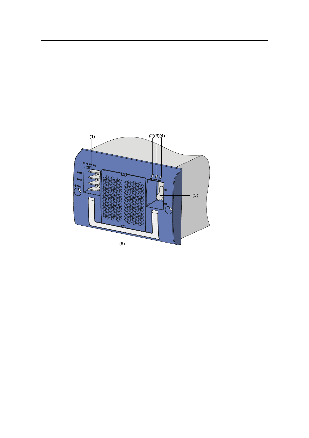
(1) Connector-retention clamp (2) Input LED
(3) Output LED (4) Fail LED
(5) Power switch (6) PSU handle
(7) AC power cord
Figure 3-11 NEPS1200-A appearance
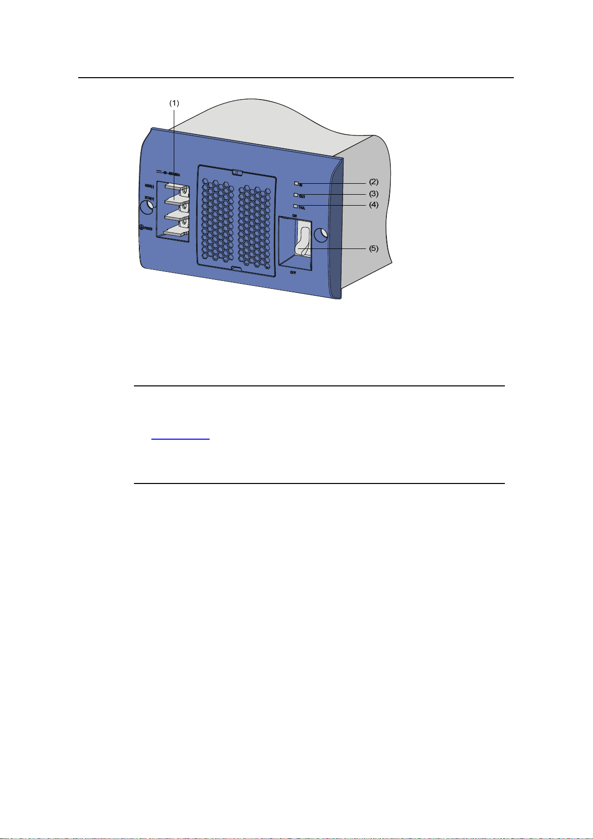
(1) Connector-retention clamp (2) Input LED
(3) Output LED (4) Fail LED
(5) Power switch (6) PSU handle
(7) AC power cord
Figure 3-12 NEPS2000-A appearance
Take the following steps to connect the AC power cord to NEPS3500-A:
1) Insert the plug at one end of the AC power cord into the socket on the
PSU.
3-12
Page 52

Installation Manual
H3C S9500 Series Routing Switches Chapter 3 Installing the Switch
2) Install the clamp to the socket of the PSU until it grips the plug.
3) Insert the other end of the power cord into an external power socket.
(1) (1)
(2)
(3)
(6)
(4)
(5)
(1) Power switch (2) Input LED
(3) Output LED (4) Fail LED
(5) PSU handle (6) AC power cord
Figure 3-13 NEPS3500-A appearance
II. Connecting DC Power Cables
The DC power cables are connected to the terminal block, and are fixed
with screws. A plastic cover plate is installed in front of the terminal block
for the sake of connection reliability.
Caution:
z Completely power off the switch before connecting th e DC power cord.
z Before removing or installing the DC power cables , you need to remo ve
the plastic cover plate. Install it after installing/removing the DC power
cables.
Take the following steps to connect the DC power cables:
1) Remove the plastic cover plate and loosen the fixing screws on the
terminal block of the DC PSU with a Philips screwdriver.
2) Connect one end of the cable with –48V OT terminals (blue) to the
NEG(–) terminal on the PSU and fasten the correspo nding fixing screw.
3-13
Page 53
Installation Manual
H3C S9500 Series Routing Switches Chapter 3 Installing the Switch
Connect the other end to the NEG (–) terminal of the source power
supply.
3) Connect one end of the cable with GND OT terminals (black) to the
RTN (+) terminal on the PSU and fasten the corresponding fixing
screw. Connect the other end to the RTN (+) terminal of the power
source.
4) Connect one end of the cable with PGND OT terminals (yellow-green)
to the PGND terminal on the PSU and fasten the corresponding fixing
screw. Connect the other end to the ground bar of the switch.
5) Install the plastic cover plate.
(1) Terminal block (2) Input LED (3) Output LED
(4) Fail LED (5) Power switch (6) PSU handle
Figure 3-14 NEPS1200-D appearance
3-14
Page 54
Installation Manual
H3C S9500 Series Routing Switches Chapter 3 Installing the Switch
(1) Terminal block (2) Input LED (3) Output LED
(4) Fail LED (5) Power switch
Figure 3-15 NEPS2000-D appearance
Note:
z NEPS3500-D is similar to NEPS2000-D in appearance, as shown in
Figure 3-15.
z The DC PSUs shown in the above figures are not equipped with plastic
cover plates.
3.7 Installing a Board
The installation procedures of SRPUs, LPUs, and service boards are
almost the same. The following section describes the installation
procedure of LPUs.
3.7.1 Installation Preparations
z Wear the ESD-preventive wrist strap, making sure that it is properly
grounded.
z Loosen the mounting screws on the blank filler panel where the SRPU
is to be installed using a Phillips screwdriver and remove the blank
filler panel.
z Prepare the LPU to be installed.
3-15
Page 55

Installation Manual
H3C S9500 Series Routing Switches Chapter 3 Installing the Switch
Note:
z Put the removed blank filler panel away for future use.
z The LPUs of the S9500 series are hot-swappable.
3.7.2 Installation Procedure
Follow the procedure below to install an LPU:
1) Turn the ejector levers on the LPU outward simultaneously with both
hands, insert the LPU straight into the chassis along the guide rails
until it stops sliding (that is, the positioning pins on the ejector levers
touch the positioning holes on the chassis).
2) Turn the ejector levers towards the front panel to drive the positioning
pins into the positioning holes.
Figure 3-16 Install an LPU
3) Fix the LPU by fastening the mounting screws on the LPU with a
Phillips screwdriver.
3.8 Installing PoE Power Supply
The S9505/S9508/S9512 uses PSE4500-A as an external PoE power
supply, which is connected to the switch through the PoE power entry
module at the front bottom of the switch to provide power for connected
powered devices (PDs ).
The following introduces the installation of PoE power supply on the
S9505.
3-16
Page 56

Installation Manual
H3C S9500 Series Routing Switches Chapter 3 Installing the Switch
3.8.1 Installation Procedure
z Wear the ESD-preventive wrist strap, making sure that it is properly
grounded.
z Remove blank filler panels in the power supply area if applicable.
3.8.2 Installing the PoE Pow er Entry Module
The PoE power entry module is hot-swa ppable.
Follow the steps below to install the PoE power entry module:
1) Unpack the PoE power entry module, which is shown in
Figure 3-17.
Figure 3-17 PoE power entry module
2) Keep the PoE power entry module in the correct letter direction. (Do
not turn it upside down. Otherwise, you will not be able to fully insert it
into the chassis due to mis-plug prevention design of the module, nor
can you fasten the chassis fixing screw.) Hold the bottom with one
hand and the front panel with the other, and then slide it smoothly
along the guide rails into the slot, until it snaps into the chassis. Make
sure the plug of the PoE power entry mod ule is fully conne cted with the
socket inside the chassis. See
Figure 3-18.
3-17
Page 57

Installation Manual
H3C S9500 Series Routing Switches Chapter 3 Installing the Switch
Figure 3-18 Install the PoE power entry module
3) Fasten the screws on the top of the PoE entry module with a Philips
screwdriver.
3.8.3 Connecting PoE Power Cables
Note:
This section only focuses on the cable connection between the external
PoE power supply and the S9500 series switch. For the installation of the
external PoE power supply, see the manual accompanying the power
supply.
I. Grounding the PoE chassis
Follow these steps to ground the PoE chass is:
1) Connect the wiring terminal (with one M6 hole) of the 6 AWG cable to
the grounding screw on the rear panel of the switch, as shown in
Figure 3-19.
2) Connect the other end of the cable to the grounding bar or other
grounding terminals.
3-18
Page 58

Installation Manual
H3C S9500 Series Routing Switches Chapter 3 Installing the Switch
(1)(1)
(1) Chassis grounding screw
Figure 3-19 Ground the PoE chassis
II. Connecting PoE power cables
1) Loosen the mounting screws on the PoE power entry module with a
Phillips screwdriver.
2) Connect one –48V OT terminal of the blue DC power cable to the NEG
(–) terminal of the PoE power entry module and fasten the mounting
screw; connect the other end to the NEG (–) terminal of the external
PoE power supply.
3) Connect the PGND OT terminal of the black DC power cable to the
RTN (+) terminal of the PoE power entry module and fasten the
mounting screw; connect the other end to the RTN (+) terminal of the
external PoE power supply.
Caution:
z Observe the polarity signs on devices and connect the cables correctly.
z Choose right cables based on the load.
3-19
Page 59

Installation Manual
H3C S9500 Series Routing Switches Chapter 3 Installing the Switch
(1) NEG(–) terminal of DC output (2) RTN(+) terminal of DC output
(3) AC input switch (4) AC input socket
Figure 3-20 Input/output of external PoE power supply
3.9 Connecting Interface Cables
3.9.1 Cable Routing Recommendations
Interface cables and power cabl es should be routed separately. You can
bind long cables with cable ties. F or specifi c binding req uirem ent s, ref er t o
Appendix A “Cable Binding”.
I. Workbench-mounted switch
All interface cables are routed to the left side (the cable management
bracket) of the chassis, and power cables are routed to the front of the
chassis.
II. Rack-Mounted switch
z The interface cables are bound on the cable management bracket on
the left side of the chassis and are routed up or down to pass through
the chassis top or the raised floor, depending on the available
equipment room condition (that is, signal cables are routed into the
chassis either from the cabling racks on the chassis top or from the
cabling trough under the floor) .
z All digital signal cable connectors should be put at the bottom of the
cabinet. Do not put them outside the cabinet.
z Power cables run along the left-front of the chassis and out of the
chassis either from the top or the raised floor, depending on the
equipment room conditions (PDF, lightning protection box, and
terminal block, etc.) in the equipment room.
3-20
Page 60

Installation Manual
H3C S9500 Series Routing Switches Chapter 3 Installing the Switch
Caution:
z Do not bind cables at the air exhaust vents of the switch to prevent
premature cable aging.
z Fix cables as near the device as possible. The cables between the fixin g
point and device interfaces must be bound loosely.
z To identify cables, you can stick labels on them. For more information,
refer to Appendix B “Engineering Lab els for Cables”.
3.9.2 Connecting Console Cable
I. Introduction
Console cable is an 8-core shielded cable. At one end of the cable is a
crimped RJ-45 connector that is to be plugged into the console port of the
switch. At the other end of the cable is a DB -9 (female) connector. You can
plug it into the 9-pin (male) serial port on the console terminal. The
following figure illustrates the console cable.
Figure 3-21 Console cable
Table 3-3 Console cable pinouts
RJ-45 Signal DB-9 Signal
1 RTS 8 CTS
2 DTR 6 DSR
3 TXD 2 RXD
4 CD 5 SG
5 GND 5 SG
6 RXD 3 TXD
7 DSR 4 DTR
3-21
Page 61

Installation Manual
H3C S9500 Series Routing Switches Chapter 3 Installing the Switch
RJ-45 Signal DB-9 Signal
8 CTS 7 RTS
II. Connecting the console cable
Take the following steps to connect the console cable, when configuring
the switch on the terminal.
1) Plug the DB-9 female connector of the console cable into the serial
port of the PC/terminal where the switch is to be configured.
2) Connect the RJ-45 connector of the console cable to the console port
of the switch.
Figure 3-22 Connect the console cable
Note:
The PC serial port is not hot-swappable, so you are not allowed to in sert or
remove the console cable into or from the PC serial port.
When connecting the console cable, first connect the DB9 end to the PC
serial port and then the RJ45 end to the console port of the switch. And
removing the console cable is just in inverse order.
When removing the console cable, first remove the RJ-4 5 end and then th e
DB9 end.
3-22
Page 62

Installation Manual
H3C S9500 Series Routing Switches Chapter 3 Installing the Switch
3.9.3 Connecting the AUX Cable
You need an AUX cable when co nfiguring t he S9500 series with the remot e
modem dial-up approach.
I. Introduction
The AUX cable is an 8-core shielded cable. At one end of the cable is an
RS-232-compliant RJ-45 connector that can be plugged into the AUX port
of the switch. At the other end is DB-9 (male) connector. You can plug it
into the DB-9 (female) port of the modem. The AUX cable is the same as
the console cable. For details, refer to
II. Connecting AUX cable
1) Plug the RJ-45 connector of the AUX cable into the AUX port of the
switch.
2) Plug the DB-9 (male) connector at the other end into the serial port of
the modem.
Figure 3-21 and Table 3-3.
3.9.4 Connecting Network Cables
I. Introduction to RJ-45 connector
The 10/100/1000Base-T ports of the S9500 series support MDI/MDI-X
auto-sensing. They are connected to category-5 shielded cables or above
that are equipped with RJ-45 connectors.
Figure 3-23 RJ-45 connector
II. Connection procedure
1) Plug one end of the network cable into the Ethernet RJ-45 port to be
connected on the switch.
2) Plug the other end of the cable into the RJ-45 port of the peer device.
3.9.5 Connecting Fiber
I. Installing fiber management tray (optional)
3-23
Page 63

Installation Manual
H3C S9500 Series Routing Switches Chapter 3 Installing the Switch
Note:
The installation method described below is based on an N68 cabinet. The
installation procedure is only for your reference if you use a non-N68
cabinet.
A fiber management tray (FMT) is installed in a cabinet for winding
redundant fibers between the S9500 and other devices.
1) Preparations
The installation prerequisites are as follows:
z The cabinet is fixed well.
z The device has been installed completely.
The installation involves the following materials:
z FMT
z M5×10 s elf-tapping screws (tw o screws for one FM T)
2) Installation Procedure
To install the fiber management tray, proceed as shown in
z Align the fiber management tray and the installation holes on the
Figure 3-24.
column of the cabinet.
z Use a Phillips screwdriver to fix each fiber management tray with two
M5×10 self-tapping screws.
Figure 3-24 Install FMTs
3-24
Page 64

Installation Manual
H3C S9500 Series Routing Switches Chapter 3 Installing the Switch
II. Introduction to fiber connector
Note:
z When selecting a fiber network facility, make sure that the type of the
connector and the fiber match the adopted optical port.
z Before connecting the fiber, make sure that the receive-end optical
power does not exceed the optical module’s upper threshold of
receiving optical power. Excessive receiving optical power is very likely
to burn the optical module.
z All the megabit and gigabit optical modules available on the S9500
series are SFP modules and all interfaces on SFP modules adopt LC
connectors.
Fiber connectors are indispen sable passive components in an optical fiber
communication system. They allow the removable connection between
optical channels, which makes the optical system debugging and
maintenance more convenient and the transit dispatching of the system
more flexible. Among various fiber connectors, only the LC connector is
introduced here.
Figure 3-25 LC connector
III. Precautions
z Be sure to install the dust cover if the optical por t is not connected to
a fiber connector.
z Some invisible rays may be emitted from the optical port if the optical
port is not connected to a fiber connect or or the du st cover is removed.
Therefore, never stare at the optical port directly.
z Fiber connectors must be protected under safe and reliable outer
packing, and be fitted with dust caps. Fiber connectors must be
installed with dust caps when they are not in use. Take care not to
scratch their end face. Replace the dust cap if it loose or polluted.
z Before connecting a fiber, use dustfree paper and absolute alcohol to
clean the end face of the fiber connector. You can brush the end face
3-25
Page 65

Installation Manual
H3C S9500 Series Routing Switches Chapter 3 Installing the Switch
only in one direction. You also need to brush the end face of the other
fiber connector.
z Never bend or curve a fiber when connecting it. After a fiber is installed
well, the bend radius must be not less than 40 mm (the minimum
dynamic bend radius is 20 D, a nd the minim um static bend ra diu s is 10
D. D indicates the outer diameter of fiber jackets).
z If the fib er has to pass through a metallic board hole, the hole mu st
have a sleek and fully filleted surface (the filleting radius must be not
less than 2 mm). When passing through a metallic board hole or
bending along the acute side of mechanical parts, the fiber must wear
jackets or cushions.
z Insert and remove a plug with care. Never exert a fierce force to the
fiber or plug; otherwise the plug may be damaged or the fiber may be
broken. Never pull, press or extrude the fiber fierce ly. For the allowed
maximum tensile load and crush load, refer to
Table 3-4.
Table 3-4 Allowed maximum tensile force and crush load
Period of force Tensile load (N)
Short period
Long term
150 500
80 100
Crush load (N/100
mm)
IV. Connection procedure
1) Connect one end of the fiber to the SFP module of the S9500 series.
2) Connect the other end of the fiber to the peer device.
3-26
Page 66

Installation Manual
H3C S9500 Series Routing Switches Chapter 3 Installing the Switch
3.10 Verifying the Installation
Warning:
Make sure that you have turned off the power before checking the
installation in case of bodily injury and device damage.
After installing the switch, verify the installation against the following list.
For the successful installation, all items must be norma l.
Table 3-5 Installation checklist
Item Normal
Console cable
PGND wire
Power cables
SRPUs
LPUs/service boards
Fan tray(s)
PSUs
Abnormal
(Description)
3-27
Page 67

Installation Manual
H3C S9500 Series Routing Switches Table of Contents
Table of Contents
Chapter 4 Commissioning the Switch......................................................................................... 4-1
4.1 Setting Up Configuration Environment .............................................................................. 4-1
4.1.1 Setting Up Configuration Environment.................................................................... 4-1
4.1.2 Setting Terminal Parameters .................................................................................. 4-1
4.2 Powering On the Switch .................................................................................................... 4-4
4.2.1 Checklist for Switch Power-On................................................................................ 4-4
4.2.2 Powering on the Switch........................................................................................... 4-5
4.2.3 Verifying after Power-on (Recommended).............................................................. 4-5
4.2.4 Boot Interface.......................................................................................................... 4-5
i
Page 68

Installation Manual
H3C S9500 Series Routing Switches Chapter 4 Commissioning the Switch
Chapter 4 Commissioning the Switch
4.1 Setting Up Configuration Environment
4.1.1 Setting Up Configuration Environment
Connect a terminal (a PC in this example) to the switch with the console cable.
Figure 4-1 Connect a PC to the switch with a Console cable
4.1.2 Setting Terminal Parameters
This section describes how to set the terminal parameters.
1) Start the PC, and run the terminal emulation program. The following uses a PC
running Windows XP HyperTerminal as an example.
2) Select Start > Programs > Accessories > Communications > HyperTerminal
to access the HyperTerminal window. Click
connection. The Connection Description dialog box appears, a s shown in
4-2. .
in the window to set up a new
Figure
4-1
Page 69

Installation Manual
H3C S9500 Series Routing Switches Chapter 4 Commissioning the Switch
Figure 4-2 Connection Description interface of HyperTerminal
3) Enter the name of the new connection in the Connection Description dialog box,
and click OK. The system displays the interface shown in
Figure 4-3. Select a port
in the Connect using drop-down list.
Figure 4-3 Select a port for the HyperTerminal connection
4) Set serial port parameters. Set the bits per second to 9600, data bits to 8, parity to
none, stop bits to 1, and flow control to none.
4-2
Page 70

Installation Manual
H3C S9500 Series Routing Switches Chapter 4 Commissioning the Switch
Figure 4-4 Set serial port parameters
5) Click OK after setting the serial port parameters to enter the HypterTerminal
window, as shown in
Figure 4-5.
Figure 4-5 HyperTerminal window
4-3
Page 71

Installation Manual
H3C S9500 Series Routing Switches Chapter 4 Commissioning the Switch
6) Select Properties in the HyperTermin al window to access the Properties window.
Click Settings in the Window (as shown in
Figure 4-6), select VT100 for terminal
emulation, and click OK.
Note:
You are recommended to select the Windows keys option button.
Figure 4-6 Set the terminal emulation parameters
4.2 Powering On the Switch
4.2.1 Checklist for Switch Power-On
Before powering on the switch, make sure that:
z The interface cables, power cables and the grounding cable are correctly
connected.
z The power outlet voltage is the same as the one indicated on the switch label.
4-4
Page 72

Installation Manual
H3C S9500 Series Routing Switches Chapter 4 Commissioning the Switch
z The console cable is correctly connected, the console terminal or PC is powered
on, and the terminal parameters are properly configured.
Caution:
Before powering on the switch, learn where the power switch is locat ed so that you can
disconnect the power supply in time in case of an emergency.
4.2.2 Powering on the Switch
To power on the switch, follow the procedure below:
z Turn on the power switch of the power source providing power to the switch.
z Turn on the power switch of the PWR on the switch.
4.2.3 Verifying after Power-on (Recommended)
To ensure the configuration works that you will make on the switch, you are
recommended to check the switch after powering it on to make sure that:
z The cooling system is working. In this case, you can hear the noise caused by fan
rotation and feel that there is air exhausted out.
z All the system LEDs on the SRPUs function normally.
4.2.4 Boot Interface
The S9505 switch is used as an example in this section.
The following is the information that will be output at the console terminal when you
power on the switch.
ZBB_TEST
Starting...
******************************************
* *
* H3C S9500 Bootrom, Version 206 *
* *
******************************************
Copyright(C) 2004-2007 Hangzhou H3C Technologies Co.,Ltd.
All rights reserved.
CPU type : MPC755
CPU L2 Cache : 1024KB
CPU Clock Speed : 400MHz
BUS Clock Speed : 100MHz
4-5
Page 73

Installation Manual
H3C S9500 Series Routing Switches Chapter 4 Commissioning the Switch
Memory Size : 512MB
Board self testing...........................
The board is steady
SlotNo of this board is 7
The MCX is existent
BootRom main system CRC check is OK
82559 register testing is OK
EPLD1 testing is OK
EPLD2 testing is OK
16c2552 register testing is OK
Please check LEDs......................LED testing finished
The switch's Mac address is 00e0.fc33.4512
Press Ctrl+B to enter Boot Menu... 0
Auto-booting...
Boot from primary file
Boot from cf:/S9500.app
Initialize CF card...done
Loading from CF card...done
Booting from CF card
Be sure the BaudRate is 9600bps!
Decompress
Image................................................................
..........................................................................
......
.........OK!
Starting at 0x10000......
User interface con0 is available.
Press ENTER to get started.
The above prompt information appears when the switch completes its boot sequence.
Press <Enter> to begin configuring the switch at the prompt “<H3C>”.
Note:
The S9500 series provide abundant command views. For more information about the
configuration commands and the Command Line Interface (CLI), see H3C S9500
Series Routing Switches Operation Manual.
4-6
Page 74

Installation Manual
H3C S9500 Series Routing Switches Table of Contents
Table of Contents
Chapter 5 Troubleshooting and Maintaining the Switch........................................................... 5-1
5.1 Troubleshooting the Switch ...............................................................................................5-1
5.1.1 Troubleshooting the Console Terminal...................................................................5-1
5.1.2 Troubleshooting the PSU........................................................................................ 5-2
5.1.3 Troubleshooting the Fan Tray(s)............................................................................. 5-2
5.1.4 Troubleshooting LPUs............................................................................................. 5-3
5.2 Hardware Maintenance...................................................................................................... 5-4
5.2.1 Replacing a PSU.....................................................................................................5-4
5.2.2 Replacing and Cleaning the PSU Air Filter............................................................. 5-6
5.2.3 Replacing and Cleaning the Chassis Air Filter........................................................5-8
5.2.4 Replacing and Installing a Card.............................................................................. 5-9
5.2.5 Replacing the Fan Tray.........................................................................................5-10
5.3 Software Upgrade............................................................................................................5-13
5.3.1 Recommended Upgrade Procedure..................................................................... 5-13
5.3.2 Local Loading through Boot Menu........................................................................5-14
5.3.3 Local or Remote Loading through CLI.................................................................. 5-23
5.3.4 Troubleshooting Software Upgrade ...................................................................... 5-25
5.3.5 Password Loss...................................................................................................... 5-25
i
Page 75

Installation Manual H3C S9500 Series Routing Switches Chapter 5 Troubleshooting and Mai ntaining the Switch
Chapter 5 Troubleshooting and Maintaining the
Switch
5.1 Troubleshooting the Switch
Although the S9500 series have undergone a comprehensive and strict factory test
before delivery, there might be some fault occurring due to improper installation and
initial configuration. This chapter describes how to troubleshoot the S9500 series.
5.1.1 Troubleshooting the Console Terminal
If the system is normal after the Switch is powered on, the booting information will be
displayed on the Console terminal. If the configuration system has failed, the Console
terminal may give illegible output or nothing at all.
I. The terminal gives no displays after the Switch is powered on
In this case, you should check whether:
z The power system is working normally.
z The SRPU is working normally.
z The Console cable has been connected to the Console port on the SRPU.
If no problem has been found in the above checking, the symptom is very likely to be
caused by the errors listed below.
z The Console cable is not connected to the right serial port, that is, t he port in use is
not the one configured on the terminal.
z There are Console terminal parameter errors. (According to the parameter setting
requirements, you should set the baud rate to 9600, data bits to 8, parity to None,
stop bits to 1, flow control to None, and select VT100 as terminal emulation.)
z The Console cable is not in good condition.
II. The terminal gives illegible characters.
This symptom is very likely caused by a Console terminal setting error. In this case,
check that you have set the baud rate to 9600, data bit s to 8, parity to None, stop bits to
1, flow control to None, and select VT100 as terminal emulation.
5-1
Page 76

Installation Manual
H3C S9500 Series Routing Switches Chapter 5 Troubleshooting and Mai ntaining the Switch
5.1.2 Troubleshooting the PSU
Table 5-1 Description of the LEDs on PSU
LED Status Meaning
Steady ON
Power input is normal, and the power switch is in
the ON shift.
Input
OFF
Power input is not normal or power input is not
available.
Steady ON The output of the PSU is normal.
Output
OFF The output of the PSU is not normal.
Steady ON The PSU is faulty.
FAIL
OFF The PSU works properly.
The following are PSU faults that may occur and the method s used for troubleshooting.
z The Input LED (green) and Output LED (green) stay ON, but the display power
command shows that the PSU is not in position (but the other PSU operates
normally). Such a problem is likely caused because of the poor contact between
the PSU and the backplane due to a badly seated PSU. In this case, switch off the
power supply, loosen the captive screws on the PSU, push the PSU into the
chassis a little bit, tighten the captive screws, and switch on the power supply to
check that the normal state is resumed.
z The Input LED (green) and Output LED (green) are OFF. In this case, check that
the power cords are connected correctly, the power cords are in good condition,
and the power switch has been put in the ON position.
z The Fail LED (red) is ON. In this case, check that the correct power voltage is in
use (i.e., 90 to 264 VAC, 50-60 Hz for AC PSU, and -36 to -72 VDC for DC PSU).
z The Fail LED (red) is ON. In this case, check that the air filter protecting the fan
tray is clean. Excessive dust accumulated on the air filter will block the fan tray
from free ventilation and even lead to power supply failure.
Note:
If you cannot solve the problem after going through the above checking steps, contact
H3C technical support.
5.1.3 Troubleshooting the Fan Tray(s)
The S9500 series provide two LEDs on the fan tray. You can read them and know
whether the fans are normal.
5-2
Page 77

Installation Manual
H3C S9500 Series Routing Switches Chapter 5 Troubleshooting and Mai ntaining the Switch
Table 5-2 Description of fan tray LEDs
LED Status Meaning
RUN (Green)
Steady ON The fan tray works normally.
OFF The fan tray is faulty.
Steady ON The fan tray is faulty.
ALM (Red)
OFF The fan tray works normally.
Note:
The ALM LED on the fan tray keeps ON for 2 to 3 seconds when the switch i s powered
on.
If the RUN LED of the fan tray is OFF, make sure that:
z The fan tray has been well seated.
z All the cables connecting the fan tray and the backplane have been correctly
connected and are in good condition.
z The fans are working normally.
z The rotation of the fans has not been blocked.
z The blank filler panels have been inserted into those LPU slots.
5.1.4 Troubleshooting LPUs
The S9500 series provide LPUX LEDs on the SRPU for the user to observe the state of
these LPUs.
Note:
z For the S9505, LPU 0 to LPU 4 correspond to Slots 2 to 6 respectively.
z For the S9508/S9508V, LPU 0 to LPU 7 correspond to Slots 0 to 3 and Slots 6 to 9
respectively.
z For the S9512, LPU 0 to LPU 11 correspond to Slots 0 to 5 and Slots 8 to 13
respectively.
For the meanings of LEDs, refer to
Table 5-3.
5-3
Page 78

Installation Manual
H3C S9500 Series Routing Switches Chapter 5 Troubleshooting and Mai ntaining the Switch
Table 5-3 Description of LPU LEDs
LED Status Meaning
Steady ON The card is faulty.
Steady OFF The card is faulty or out of position.
RUN
Normal blinking (1 Hz) The card works normally.
Fast blinking (8 Hz)
Steady ON There is an alarm.
ALM
Steady OFF
5.2 Hardware Maintenance
5.2.1 Replacing a PSU
Caution:
z When installing or replacing a PSU while power is being supplied, you must take
care in the operation procedures and safety with electricity. Do not touch any
exposed wires, terminals or any parts of the product marked with a dangerous
voltage label to avoid bodily injury.
z The PSUs of the S9500 series are hot-swappable. Before removing a PSU, you
must turn off its power switch.
z If you do not want to install a PSU, insert a blank filler panel into the PSU slot for
dust-proofing.
The RUN LED is steadily on or is blinking
fast when the card is booted. If the LED
always blinks fast, the registration failed.
There is no alarm, or the card is out of
position.
I. Removing a PSU other than NEPS3500-A
The following procedure applies to all NEPS PSUs except NEPS3500-A.
1) Move the power switch on the PSU to the OFF position if it is in the ON position.
Disconnect the power source and unplug the power cord.
2) Remove the captive screws on the both sides of the PSU panel with a Phillips
screwdriver.
3) Grasp the air filter cover by the upper and lower edges with your index finger and
the thumb, and gently remove the air filter cover.
4) Pull the PSU gently along the guides out of the chassis, as shown in
5-4
Figure 5-1.
Page 79

Installation Manual
H3C S9500 Series Routing Switches Chapter 5 Troubleshooting and Mai ntaining the Switch
Figure 5-1 Remove the PSU
II. Removing NEPS3500-A
Follow these steps to remove NEPS3500-A:
1) Remove the 1800 W sub-PSUs.
2) Remove the NEPS3500-A enclosure.
Table 5-4 Procedure for removing NEPS3500-A
Step Sub-step
1) Press down the sub-PSU lever so that the sub-module is
Remove 1800
W sub-PSUs
separated from the backplane (refer to
2) Hold the handle of the sub-PSU with one hand and the bottom
with the other hand, and gently pull the sub-PSU out of the
chassis along the guide rails.
1) Move the power switch on the PSU to the OFF position if it is
in the ON position.
Remove the
AC power
enclosure
2) Remove the bail latch and unplug the power cord.
3) Remove the captive screws on the both sides of the PSU
panel with a Phillips screwdriver.
4) Hold the handle on the PSU enclosure and gently pull the
PSU enclosure out of the chassis along the guide rails.
Figure 5-2).
Figure 5-2 Remove the 1800W sub-PSU
5-5
Page 80
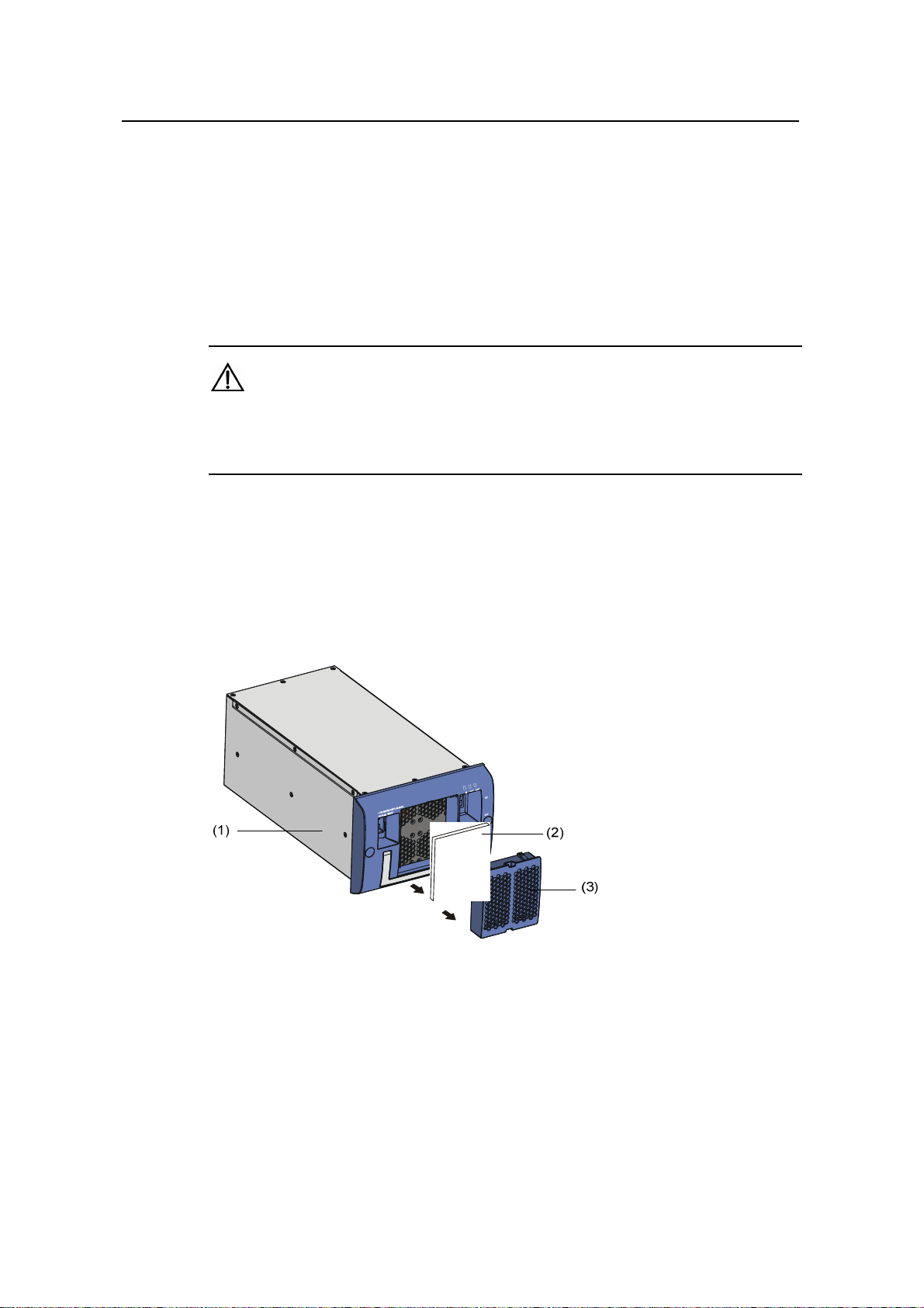
Installation Manual
H3C S9500 Series Routing Switches Chapter 5 Troubleshooting and Mai ntaining the Switch
III. Installing a PSU
Refer to section 3.6 “Installing a PSU” in Chapter 3 “Installing the Switch”.
5.2.2 Replacing and Cleaning the PSU Air Filter
The air filters on the AC PSUs and DC PSUs can be replaced in a similar way even
though they have different shapes.
Caution:
You are strongly recommended to clean the air filter semi-monthly to guarantee
adequate ventilation.
I. Removing and cleaning the PSU air filter
1) Clutch the air filter by the upper and lower edges with your index finger and the
thumb, and pull the air filter out gently.
2) Take the black air filter mesh off.
3) Wash the mesh using clean water and air-dry it, taking care not to rub it.
(1) PSU (2) Air filter mesh (3) Air filter cover
Figure 5-3 Remove the air filter from the DC PSU
5-6
Page 81

Installation Manual
H3C S9500 Series Routing Switches Chapter 5 Troubleshooting and Mai ntaining the Switch
(1) PSU (2) Air filter mesh (3) Air filter cover
Figure 5-4 Remove the air filter from the AC PSU
II. Installing the PSU air filter
1) Check that the black mesh has been nested in the air filter cover, as shown in
Figure 5-5.
Figure 5-5 Install the PSU air filter (1)
2) Clutch the air filter cover by the upper and lower edges with your index finger and
thumb and push it inside the PSU with an even force, as shown in
Figure 5-6.
5-7
Page 82

Installation Manual
H3C S9500 Series Routing Switches Chapter 5 Troubleshooting and Mai ntaining the Switch
Figure 5-6 Install the PSU air filter (II)
5.2.3 Replacing and Cleaning the Chassis Air Filter
Caution:
z You are strongly recommended to clean the chassis air filter semi-monthly to
guarantee adequate ventilation.
z Now, the delivered S9505, S9508, and S9512 contain no chassis air filter. Only the
S9508V contains a chassis air filter.
For the S9500 series except the S9508V, the procedure for replacing and
cleaning/installing the chassis air filter is the same.
I. Removing, cleaning and installing the chassis air filter of the
S9505/S9508/S9512
z To remove and cleaning the chassis air filter, follow the procedure below:
1) Loosen the captive screws at the top and bottom of the air filter with a Phillips
screwdriver.
2) Hold the air filter at the left-rear by its upper and lower edges, pull part of it out of
the chassis, put one hand underneath the air filter to hold it, and pull it out slowly
along the guides.
5-8
Page 83

Installation Manual
H3C S9500 Series Routing Switches Chapter 5 Troubleshooting and Mai ntaining the Switch
Caution:
As the chassis air filter is quite long, you should hold its front end with one hand, and
bear its weight by putting the other hand underneath it when sliding it out of the chassis.
3) Rinse the air filter cover (no rubbing) without taking the mesh out. Air-dry it.
z Installing the chassis air filter
1) Hold the air filter by the front end using one hand, and support the bottom of the air
filter using the other hand, place the air filter vertically, and slide it into the chassis
along the guide rails.
2) Fix the air filter by fastening the captive screws at the top and bottom of the air filter
with a Phillips screwdriver.
II. Removing, cleaning and installing the chassis air filter of the S9508V
z To remove and clean the chassis air filter, follow the procedure below:
1) Remove the captive screws at the left and right sides of the air filter using a Phillips
screwdriver.
2) Clutch the air filter cover by the upper and lower edges using your index finger and
the thumb, and remove the air filter cover gently.
3) Pull out the nested black air filter mesh.
4) Wash the air filter mesh using water, and then air-dry it. Take care not to rub the air
filter mesh when you wash it.
z To install the chassis air filter, follow the procedure below:
1) Nest the black air filter mesh into the air filter cover.
2) Hold the air filter by the front end using one hand, and support the bottom using
the other hand, place it horizontally, and slide it into the chassis along the guide
rails.
3) Fasten the captive screws at the left and right sides of the air filter using a Phillips
screwdriver, thus installing the air filter completely.
5.2.4 Replacing and Installing a Card
The SRPU, LPUs and service boards of the S9500 series are all hot swappable. They
can be installed and removed almost in the same way. This section describes the
general procedures for removing and installing these cards.
I. Removing a card
1) Wear the ESD-preventive wrist strap and loosen the captive screws on the card
with a Phillips screwdriver.
2) Hold the ejector levers on the card with both hands and pull them outward to
separate the locking pin of the card from the backplate.
5-9
Page 84

Installation Manual
H3C S9500 Series Routing Switches Chapter 5 Troubleshooting and Mai ntaining the Switch
3) Gently pull the card out of the slot along the guides.
Figure 5-7 Remove a card
II. Installing a card
Refer to the section 3.7 "Installing a Card" in Chapter 3 “Installing the Switch”.
5.2.5 Replacing the Fan Tray
Caution:
z Do not touch exposed wires, terminals or the switch parts where dangerou s voltage
warning is given to avoid bodily injury.
z Install a new fan tray soon after removing the old one to ensure the normal working
of the switch.
For the S9500 series except the S9508V, the procedure for replacing/installing the fan
tray is the same.
Note:
z The fan tray is delivered together with the switch and you do not need to install it.
The following only describes how to replace the fan tray.
z The fan tray is hot-swappable.
5-10
Page 85

Installation Manual
H3C S9500 Series Routing Switches Chapter 5 Troubleshooting and Mai ntaining the Switch
I. Replacing the fan tray of S9505/S9508/S9512
1) Wear the ESD-preventive wrist strap. Remove the captive screws on both sides of
the fan tray. Gently pull the fan tray out of the slot along the guide rails, as shown
Figure 5-8.
in
Caution:
When you replace the fan tray on an operating switch, pull the fan tray half way out of
the chassis to disconnect the power, and wait till the fans stop rotating before pulling it
out completely. Considering that the fans may be still rotating, avoid stretching your
hands into the fan tray.
.
Figure 5-8 Replace the fan tray (1)
2) Slide the new fan tray smoothly along the guide rails until it fits into the chassis,
with its plug fully touching the socket inside the chassis.
Caution:
Do not turn the fan tray upside down. Otherwise, you will not be able to fully insert it into
the chassis due to the mis-plug prevention design of the chassis.
5-11
Page 86

Installation Manual
H3C S9500 Series Routing Switches Chapter 5 Troubleshooting and Mai ntaining the Switch
Figure 5-9 Replace the fan tray (2)
3) Fasten the captive screws on both sides of the fan tray.
II. Replacing the fan tray of S9508V
1) Wear an ESD-preventive wrist strap.
Caution:
When you replace the fan tray on an operating switch, pull the fan tray half way out of
the chassis to disconnect the power, and wait till the fans stop rotating before pulling it
out completely. Considering that the fans may be still rotating, avoid stretching your
hands into the fan tray.
2) Press the button using your thumb, and slide the fan tray out of the chassis along
the slot, as shown in
Figure 5-10.
5-12
Page 87

Installation Manual
H3C S9500 Series Routing Switches Chapter 5 Troubleshooting and Mai ntaining the Switch
Figure 5-10 Replace the S9508V fan tray (1)
3) Slide a new fan tray smoothly along the guide rails until it fits into the chassis, with
its plug fully touching the socket inside the chassis.
Figure 5-11 Replace the S9508V fan tray (2)
Note:
The S9508V fan tray has no captive screws and is fixed by two locks.
5.3 Software Upgrade
5.3.1 Recommended Upgrade Procedure
You can load the software through command line interface (CLI) and Boot menu.
1) Local loading using Boot menu:
z Loading using XModem and through Console port
5-13
Page 88

Installation Manual
H3C S9500 Series Routing Switches Chapter 5 Troubleshooting and Mai ntaining the Switch
z Loading using TFTP and through Ethernet port
z Loading using FTP and through Ethernet port
2) Local or remote loading through CLI:
z Loading using FTP
z Loading using TFTP
Note:
z When loading Boot ROM and host software, make sure that Boot ROM matches the
host software. You are recommended not to load Boot ROM frequently. You need to
load the correct Boot ROM only when the host software to be loaded does not
match the current Boot ROM.
z You can load only Boot ROM and host software of SRPUs through the Boot menu.
To load Boot ROM of LPUs, use the CLI mode.
5.3.2 Local Loading through Boot Menu
Caution:
Never hot-plug the CF card after you enter the Boot ROM menu. After replacing the CF
card, you must reboot the SRPU. Otherwise, the CF card cannot work properly.
I. Boot menu
After powering on the Switch, run Boot ROM program first and th e termin al will display
the following information:
ZBB_TEST
Starting...
*************************************************
* *
* H3C S9500 Bootrom, Version 206 *
* *
*************************************************
Copyright(c) 2004-2007 Hangzhou H3C Technologies Co., Ltd.
CPU type : MPC755
CPU L2 Cache : 1024KB
CPU Clock Speed : 400MHz
5-14
Page 89

Installation Manual
H3C S9500 Series Routing Switches Chapter 5 Troubleshooting and Mai ntaining the Switch
BUS Clock Speed : 100MHz
Memory Size : 512MB
Board self testing...........................
The board is steady
SlotNo of this board is 6
The MCX is existent
BootRom main system CRC check is OK
82559 register testing is OK
EPLD1 testing is OK
EPLD2 testing is OK
16c2552 register testing is OK
Please check LEDs......................LED testing finished
The switch's Mac address is 000f.e222.ce4d
Press Ctrl+B to enter Boot Menu... 0
Password :
Note:
To enter the Boot menu, you must press Ctrl+B within five seconds after the
appearance of the prompt “Press Ctrl-B to enter Boot menu...”. Otherwise, the program
decompression process will begin. To access the Boot menu after the Switch enters
the program decompression process, you need to restart the Switch.
Enter the correct Boot ROM password (no password has been set for the switch by
default), and the system will access the Boot menu:
Caution:
While using the Switch, keep in mind the latest Boot ROM password.
MAIN MENU
1. Boot with default mode
2. Boot from Flash
3. Boot from CF card
5-15
Page 90

Installation Manual
H3C S9500 Series Routing Switches Chapter 5 Troubleshooting and Mai ntaining the Switch
4. Enter serial submenu
5. Enter ethernet submenu
6. Modify Flash description area
7. Modify bootrom password
0. Reboot
Enter your choice(0-7)
Note:
You must ensure the upgraded host program is compatible with the existing Boot ROM
program of the LPU. Otherwise, you have to upgrade it during host program upgrade.
When loading the host program through the Boot menu, you must configure correct
attributes of the serial interface (as shown in
Figure 5-12). Otherwise, the
HyperTerminal does not respond.
Figure 5-12 Attribute settings of HyperTerminal serial interface
II. Upgrading software through console port (XModem)
z Brief introduction to XModem
XModem, a type of file transfer protocol, is broadly applied for its simplicity and good
performance. It transmits files through serial interfaces, supporting 128 bytes and 1 KB
5-16
Page 91

Installation Manual
H3C S9500 Series Routing Switches Chapter 5 Troubleshooting and Mai ntaining the Switch
in terms of data unit, checksum and CRC in terms of checking mode, and multiple
retransmissions (usually ten attempts) in the event that packet errors are found.
XModem completes transmission by the receiving program (receiver) and the sending
program (sender). In XModem, the transmission begins with the sending of negoti ation
characters from the receiver for the purpose of check mode negotiation. After passing
the negotiation, the sender is allowed to send the first data packet. Upon the re ceipt of
the complete packet, the receiver checks the packet using the agreed checking mode
and will send an ACK if the packet has passed the check and a NAK if not. Receiving
the ACK, the sender will send the next packet; receiving the NAK instead, the sender
will retransmit the previously sent packet.
z Xmodem application
1) In the Boot menu, enter 4, press Enter, and the system will access the serial
interface submenu:
SERIAL SUBMENU
1. Download file to SDRAM through serial interface and boot
2. Download file to Flash through serial interface
3. Download file to CF card through serial interface
4. Modify serial interface boot parameter
0. Return to main menu
Enter your choice(0-4):4
2) Enter 4 in the serial interface submenu and press Enter to access the following
interface for setting the parameters of the downloading serial interface:
1: 9600(default)
2: 19200
3: 38400
4: 57600
5: 115200
0: Return to serial submenu
please select an appropriate baudrate:
Enter your choice(1-5): 5
3) Select the appropriate downloading speed as needed. For example, enter 5 to
select the downloading speed of 115200 bps, press Enter, and the system will
display the following information in the terminal:
BaudRate is 115200 bps. Please change the terminal's speed to 115200 bps
4) At the prompt displayed in the last step, change the baud rate on the Console
terminal to the same one selected for software downloading, disconnect the
terminal and connect it again, press Enter, and the terminal will access the serial
interface submenu again:
SERIAL SUBMENU
1. Download file to SDRAM through serial interface and boot
2. Download file to Flash through serial interface
3. Download file to CF card through serial interface
5-17
Page 92

Installation Manual
H3C S9500 Series Routing Switches Chapter 5 Troubleshooting and Mai ntaining the Switch
4. Modify serial interface boot parameter
0. Return to main menu
Enter your choice(0-4):3
Note:
z After changing the baud rate, you must close the terminal emulation program and
start it again for at least once in order to validate the new baud rate.
z In a Windows 98 operating system environment, you can perform the operation s of
disconnection and reconnection after changing the baud rate. In a Windows 2000
operating system, however, you must disconnect the terminal before setting the
baud rate and connect the terminal after finishing the work.
z Since the software Release 2100 and later is quite large in size, you have to
download it into the CF card.
5) Select a right place to store the downloaded file as needed. For example, enter 3
at the prompt displayed in the last step to download the file into the CF card of the
switch, press Enter, and the system will display the following information on the
terminal:
Please Select File .
XMODEM downloading ...CCC
6) Select Transfer > Send File in the terminal window. Click Browse in the pop-up
dialog box (shown as the following figure), select the desired application, and
change the protocol used for downloading to XModem.
Figure 5-13 Send File dialog box
7) Click Send and the following interface pops up.
5-18
Page 93

Installation Manual
H3C S9500 Series Routing Switches Chapter 5 Troubleshooting and Mai ntaining the Switch
Figure 5-14 Sending file page
8) After downloading the program successfully, the system begins to write the data
into the CF card. The downloading operation will end upon a successful write
operation. Then, the system will access the serial interface submenu again, and
the user can make selection as needed. The details will not be covered here.
XMODEM downloading ...CCC download successfully!
Free CF card space : 169902080 bytes
Writing CF card....Done
SERIAL SUBMENU
1. Download file to SDRAM through serial interface and boot
2. Download file to Flash through serial interface
3. Download file to CF card through serial interface
4. Modify serial interface boot parameter
0. Return to main menu
Enter your choice(0-4):
III. Upgrading software through management Ethernet port (TFTP)
z Introduction to TFTP
Trivial file transfer protocol (TFTP) is well suited to the file transfer between a server
and a client that do not need complex interaction.
In TFTP, the transmission is initiated by the client. When downloading a file, the client
sends a read request packet to the TFTP server, receives the data packets from the
server, and sends the ACK to the server. When uploading a file, the client sends a write
request packet to the TFTP server, then sends the data packets to the server, and
receives the ACK from the server. The TFTP transmission files have two forms, i.e.,
binary for program transmission and ASCII for text transmission.
5-19
Page 94

Installation Manual
H3C S9500 Series Routing Switches Chapter 5 Troubleshooting and Mai ntaining the Switch
Following is the upgrading procedure described taking the S9512 working as a TFTP
Client as an example.
z TFTP upgrade procedure
1) Connect the Switch to a PC where the desired file is located via the
management/upgrade Ethernet port. (In this case, you should know the IP
address of the PC. At the same time, connect the Switch to an external PC (that
can be the same one that contains the desired file) via the Console port.
2) Run the TFTP Server program on the PC connected to the management/upgrade
Ethernet port, and specify the path for upgrading the application files.
3) Run the terminal emulation program on the PC connected to the Console port, and
boot the switch to access the Boot menu.
4) Enter 5 in the Boot menu. Press Enter and the system will access the download
application program menu.
ETHERNET SUBMENU
1. Download file to SDRAM through ethernet interface and boot
2. Download file to Flash through ethernet interface
3. Download file to CF card through ethernet interface
4. Modify ethernet interface boot parameter
0. Return to main menu
Be sure to select 4 to modify boot parameter before downloading!
Enter your choice(0-4): 4
5) Enter 4 in the download application program menu to select TFTP for the software
upgrading. Press Enter and then you can begin to set the related TFTP
parameters:
Note: Two protocols for download, tftp & ftp.
You can modify the flags following the menu.
tftp--0x80, ftp--0x0.
Note:
The information above prompts you to set the flags to 0x80 when you download files
using TFTP and to 0x0 if using FTP.
'.' = clear field; '-' = go to previous field; ^D = quit
boot device :fei0
processor number :
host name : 9500 ,
file name : 9500.app
inet on ethernet (e) : 1.1.1.1
inet on backplane (b):
5-20
Page 95

Installation Manual
H3C S9500 Series Routing Switches Chapter 5 Troubleshooting and Mai ntaining the Switch
host inet (h) : 1.1.1.2
gateway inet (g) :
user (u) :
ftp password (pw) (blank = use rsh):
flags (f) :0x80
target name (tn) :
startup script (s) :
other (o) :
Write flash...done!
6) After you provide the required information, the system accesses the Ethernet
interface submenu again:
ETHERNET SUBMENU
1. Download file to SDRAM through ethernet interface and boot
2. Download file to Flash through ethernet interface
3. Download file to CF card through ethernet interface
4. Modify ethernet interface boot parameter
0. Return to main menu
Enter your choice(0-4): 2
7) At the prompt displayed in step 6, select a place for the downloaded file (for
example, select 3 to download the file to the CF card), and press Enter. The
system will display the following information on the terminal screen:
Attached TCP/IP interface to fei0.
Attaching network interface lo0... done.
boot device : fei0
unit number : 0
processor number : 0
host name : 9500
file name : 9500.app
inet on ethernet (e) : 1.1.1.1
host inet (h) : 1.1.1.2
flags (f) : 0x80
Prepare for loading....OK
Loading......done
Free CF card space : 203915264 bytes
Writing CF card.....
......Done
8) The information displayed in the last step means a successful file downloading
operation. In this case, the system accesses the Ethernet interface submenu
again and the user can make selection as needed. The details will not be covered
here.
5-21
Page 96

Installation Manual
H3C S9500 Series Routing Switches Chapter 5 Troubleshooting and Mai ntaining the Switch
ETHERNET SUBMENU
1. Download file to SDRAM through ethernet interface and boot
2. Download file to Flash through ethernet interface
3. Download file to CF card through ethernet interface
4. Modify ethernet interface boot parameter
0. Return to main menu
Enter your choice(0-4):
IV. Upgrading software through management Ethernet port (FTP)
z Introduction to FTP
The S9500 series applications can also be updated through the Ethernet port and using
FTP.
Following is the upgrading procedure, using the S9512 working as a n FTP Cli ent as an
example.
z Upgrade procedure
1) Connect the Switch to the PC containing the desired file via the
management/upgrade Ethernet port. (In this case, you should know the IP
address of the PC. At the same time, connect the Switch to an external PC (that
can be the same one that contains the desired file) via the Console port.
2) Run FTP Server on the PC connected to the management/upgrade Ethernet port,
specify the path of the upgrading file, and set the login username and password.
3) Run the terminal emulation program on the PC connected to the Console port, and
boot the Switch to access the Boot menu.
4) For Steps 4 to 8, see the corresponding steps in the upgrading procedure via
TFTP for reference.
Note:
If you want to download files using FTP, please set the flags to 0x0 when setting the
Ethernet interface parameters.
After downloading the host program through the Boot menu, you m ust spe cify it as the
next boot program. In the following example, the host program is 9500.app.
MAIN MENU
1. Boot with default mode
2. Boot from Flash
3. Boot from CF card
4. Enter serial submenu
5. Enter ethernet submenu
5-22
Page 97

Installation Manual
H3C S9500 Series Routing Switches Chapter 5 Troubleshooting and Mai ntaining the Switch
6. Modify Flash description area
7. Modify bootrom password
0. Reboot
Enter your choice(0-7):
Enter your choice(0-7): 6
Please input '0' or '1' ('0':Boot from Flash, '1':Boot from CF card)
BootDev = 1
CF card FileName = S9500-XN.app 9500.app
The file name you input is 9500.app,
Are you sure? Yes or No(Y/N)Y
5.3.3 Local or Remote Loading through CLI
If your terminal is connected to the switch over a network, you can load Bo ot ROM and
host program at the remote through CLI.
I. Loading using FTP
Run FTP server on a local PC, provided you have configure d username and p assword
and have set the correct file directory. Suppose IP address of the PC is 10.10.110.1.
Log on to the switch using Telnet or through the Console port to send host program to
the switch using FTP.
Suppose that the main boot file is SWITCH002.app; the active host program is
SWITCH001.app; the Boot ROM program is SWITCHbtm.btm. You can follow these
steps after logging on to the switch.
1) Download the software to the switch using FTP.
<H3C> ftp 10.10.110.1
Trying ...
Press CTRL+K to abort
Connected.
220 WFTPD 2.0 service (by Texas Imperial Software) ready for new user
User(none):9500
331 Give me your password, please
Password:
230 Logged in successfully
[ftp] get SWITCH002.app SWITCH002.app
[ftp] get Switchbtm.btm Switchbtm.btm
[ftp] bye
5-23
Page 98

Installation Manual
H3C S9500 Series Routing Switches Chapter 5 Troubleshooting and Mai ntaining the Switch
Note:
If the switch has two SRPUs, you also can copy the host and Boot ROM program files
to the standby SRPU.
2) Specify the next boot program. If the switch has two SRPUs, specify the load
programs respectively for the active and standby SRPUs. Suppose the current
standby SRPU is at slot 7.
z Load Boot ROM program
<H3C> boot bootrom CF:/Switchbtm.btm slot 6
<H3C> boot bootrom CF:/Switchbtm.btm slot 7
z Load host program
<H3C> boot boot-loader CF:/SWITCH002.app
<H3C>boot boot-loader CF:/SWITCH002.app
<H3C> display boot-loader
The app to boot of board 6 at the next time is: flash:/SWITCH002.app
The app to boot of board 6 at this time is: flash:/SWITCH001.app
The app to boot of board 7 at the next time is: flash:/SWITCH002.app
The app to boot of board 7 at this time is: flash:/SWITCH001.app
<H3C> reboot
Caution:
z You must reboot the switch using the reboot command to validate the host
program.
z Make sure that you have saved other configurations before reboot. Otherwise, they
might not survive a reboot.
z Power-off is forbidden during loading process.
Boot ROM and host program loading is completed now.
II. Remote and local loading using TFTP
Using TFTP is similar to using FTP in remote and local loading via comm ands. The only
difference is that you use the tftp get command to download software to the switch. In
this case, the switch can only be used as a TFTP client to downloa d the software to its
CF card from the TFTP server . The remaining step s after downl oading are the same as
those of remote loading using FTP.
5-24
Page 99

Installation Manual
H3C S9500 Series Routing Switches Chapter 5 Troubleshooting and Mai ntaining the Switch
5.3.4 Troubleshooting Software Upgrade
These types of problems may occur during software upg rade:
I. No response from SRPU serial interface
Check whether the serial interface cable is in good condition and if it s attributes are set
correctly (9600 bps).
II. Uploading configuration file or host program using FTP fails
Please check that
z The configuration is correct and if the FTP server is started.
z The Flash or the CF card has enough space for the target files.
z The FTP flag is selected and is set 0x0.
III. No configuration saving during LPU reboot
Before saving the configuration, you must check the operating status of the LPU. Do
not save the configuration during the LPU reboot. Otherwise, the configuration you
want to save may be lost.
IV. LPU program loading fails or you cannot register for a long period
z Check LPU type to see if this type is supported on the current host program.
z Check whether the LPU Boot ROM program matches the host program before
upgrade.
z Check whether LPUs are well seated.
z Insert an LPU to different slots to check whether it is OK.
z Check whether the host program exists and if the current host program is the
running one.
V. Insufficient Flash memory
z Empty the recycle bin when the LPU starts.
z Delete the unused files in the Flash.
z Load the files into the CF card.
5.3.5 Password Loss
If the Super password or Boot ROM password of the Switch is lost, contact the local
agent or H3C technical support.
5-25
Page 100

Installation Manual
H3C S9500 Series Routing Switches Table of Contents
Table of Contents
Appendix A Cable Management...................................................................................................A-1
A.1 Correct Use of Labels........................................................................................................A-1
A.2 Cable Management Requirements....................................................................................A-1
i
 Loading...