

Page 1

H3C S9500 Series Routing Switches
Installation Manual
Hangzhou H3C Technologies Co., Ltd.
http://www.h3c.com
Manual Version: T2-08045T-20070425-C-1.01
Product Version: Release 1278(S9500-CMW310-R1278)
Page 2

Copyright © 2006-2007, Hangzhou H3C Technologies Co., Ltd. Ltd. and its licensors
All Rights Reserved
No part of this manual may be reproduced or transmitted in any form or by any means
without prior written consent of Hangzhou H3C Technologies Co., Ltd.
Trademarks
H3C, , Aolynk, , H3Care,
Neocean, NeoVTL, SecPro, SecPoint, SecEngine, SecPath, Comware, Secware,
Storware, NQA, VVG, V
HUASAN are trademarks of Hangzhou H3C Technologies Co., Ltd.
All other trademarks that may be mentioned in this manual are the property of their
respective owners.
Notice
The information in this document is subject to change without notice. Every effort has
been made in the preparation of this document to ensure accuracy of the content s, but
all statements, information, and recommendations in this document do not constitute
the warranty of any kind, express or implied.
To obtain the latest information, please access:
http://www. h3c.com
Technical Support
customer_service@h3c.com
http://www. h3c.com
, TOP G, , IRF, NetPilot,
2
G, VnG, PSPT, XGbus, N-Bus, TiGem, InnoVision and
Page 3
About This Manual
Related Documentation
The related manuals are listed in the following table.
Manual Description
H3C S9500 Series Routing Switches
Operation Manual
It includes getting started, port, VLAN,
network protocols, routing protocols,
multicast protocols, QoS/ACL, MPLS,
STP, security, reliability, system
management, PoE, NAT-URPF-VPLS,
integrated management and appendix.
Organization
H3C S9500 Series Routing Switches Installation Manual is organized as follows:
H3C S9500 Series Routing Switches
Command Manual
Chapter Contents
1 Product Overview profiles the architecture and
2 LPU Modules focuses on the LPU boards of the S950 0
3 Installation Preparations lists the preparations and precautions
4 Switch Installation details the installation of the chassis,
5 System Debugging concentrates on the initial poweron and
It introduces all commands available in
the S9500 series, as well as a command
index.
specifications of the S9500 series.
series.
before installation.
boards and cable connection for the
S9500 series.
booting of the S9500 series.
6 Switch Monitoring and Maintenance presents the use of engineering labels.
7 Appendix A introduces the use of engineering labels.
8 Appendix B introduces the installation of the B68
cabinet.
9 Appendix C introduces the lighting protection for the
S9500 series.
Page 4
Conventions
The manual uses the following conventions:
I. Command conventions
Convention Description
Boldface
italic
[ ]
{ x | y | ... }
[ x | y | ... ]
{ x | y | ... } *
[ x | y | ... ] *
# A line starting with the # sign is comments.
The keywords of a command line are in Boldface.
Command arguments are in italic.
Items (keywords or arguments) in square brackets [ ] are
optional.
Alternative items are grouped in braces and separated by
vertical bars. One is selected.
Optional alternative items are grouped in square brackets
and separated by vertical bars. One or none is selected.
Alternative items are grouped in braces and separated by
vertical bars. A minimum of one or a maximum of all can be
selected.
Optional alternative items are grouped in square brackets
and separated by vertical bars. Many or none can be
selected.
II. GUI conventions
Convention Description
< >
[ ]
/
Button names are inside angle brackets. For example, click
<OK>.
Window names, menu items, data table and field names
are inside square brackets. For example, pop up the [New
User] window.
Multi-level menus are separated by forward slashes. For
example, [File/Create/Folder].
III. Symbols
Convention Description
Means reader be extremely careful. Improper operation
Warning
Caution
Note Means a complementary description.
may cause bodily injury.
Means reader be careful. Improper operation may cause
data loss or damage to equipment.
Page 5

Environmental Protection
This product has been designed to comply with the requirements on environmental
protection. For the proper storage, use and disposal of this product, national laws and
regulations must be observed.
Page 6

Installation Manual
H3C S9500 Series Routing Switches Table of Contents
Table of Contents
Chapter 1 Product Overview........................................................................................................1-1
1.1 Preface............................................................................................................................... 1-1
1.2 General Architecture.......................................................................................................... 1-2
1.2.1 Chassis and Slots ................................................................................................... 1-3
1.2.2 Backplane................................................................................................................ 1-6
1.2.3 System Power Supply ............................................................................................. 1-7
1.2.4 PoE Power Supply .................................................................................................. 1-9
1.2.5 Fan Tray ................................................................................................................ 1-11
1.2.6 SRPU Module........................................................................................................ 1-11
1.2.7 LPU Modules......................................................................................................... 1-29
1.2.8 Service Processor Cards ...................................................................................... 1-30
1.2.9 System Specifications ........................................................................................... 1-32
i
Page 7
Installation Manual
H3C S9500 Series Routing Switches Chapter 1 Product Overview
Chapter 1 Product Overview
1.1 Preface
H3C S9500 Series Routing Switches (hereinafter referred to as S9500 series) are
orientated to operate at the convergence layer of a large MAN, or at the core layer of a
small MAN, or at the backbone of a large enterprise network or a campus network.
They serve as the Layer 3 devices in the switching center and convergence center.
S9500 series provide 10GE ports, redundant power systems and redundant SRPU
modules, to address multiservice, high-reliability and large-capacity needs from
high-end users.
The S9500 series currently include three models:
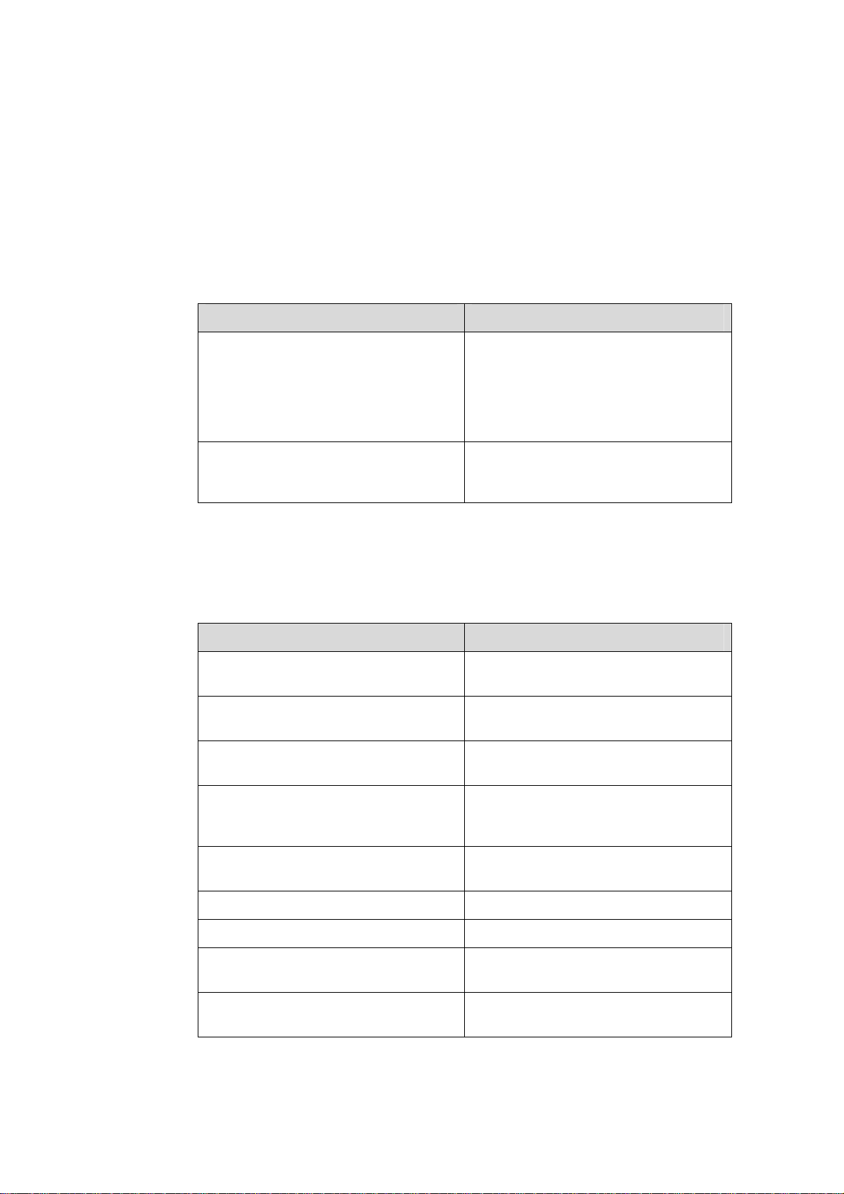
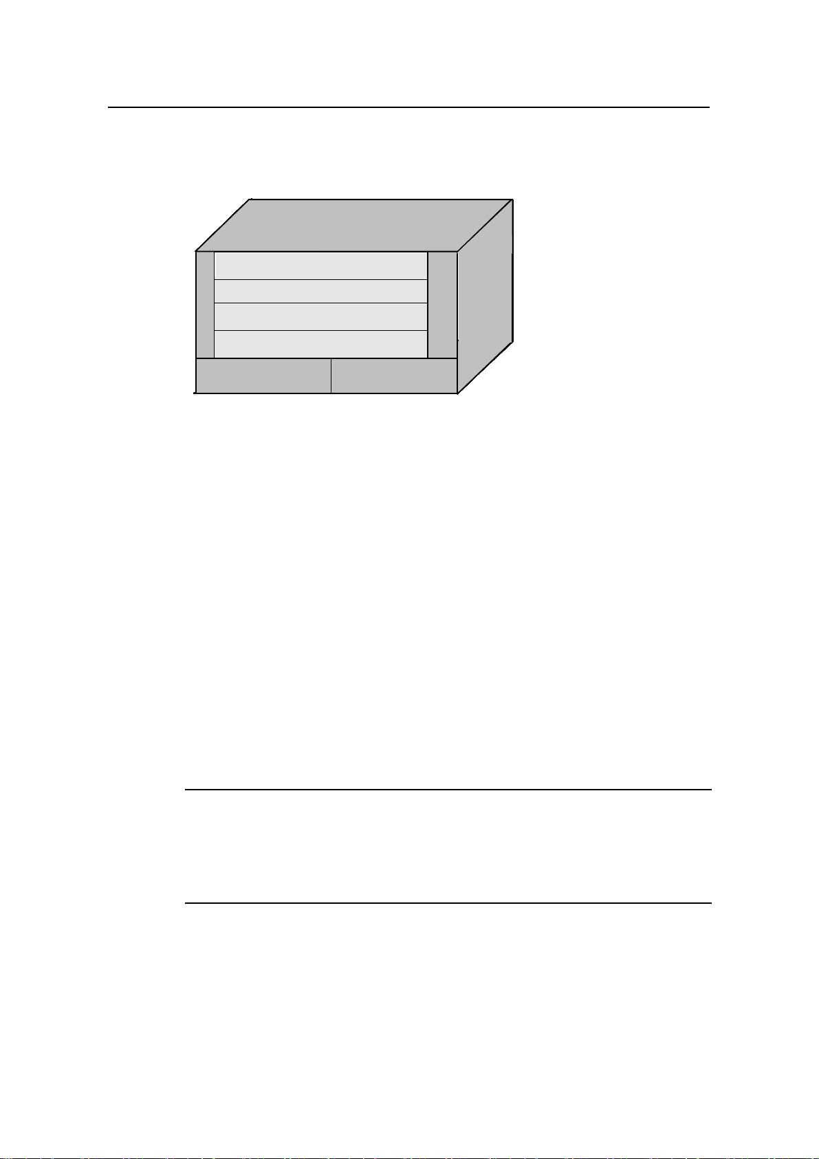
z S9502: This model provides up to 240 Gbps switching capacity. It allows (for
example) the concurrent wire-speed forwarding on 144 GE ports, 8 x 10GE ports,
144 FE electrical ports, or 60 FE optical ports.
Figure 1-1 H3C S9502
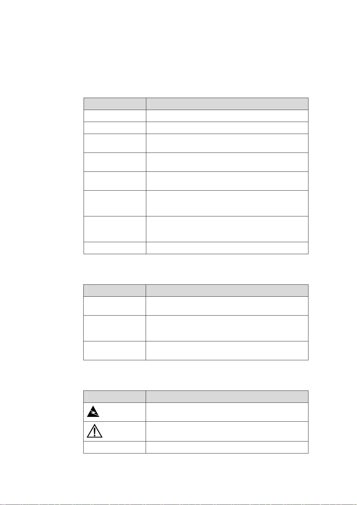
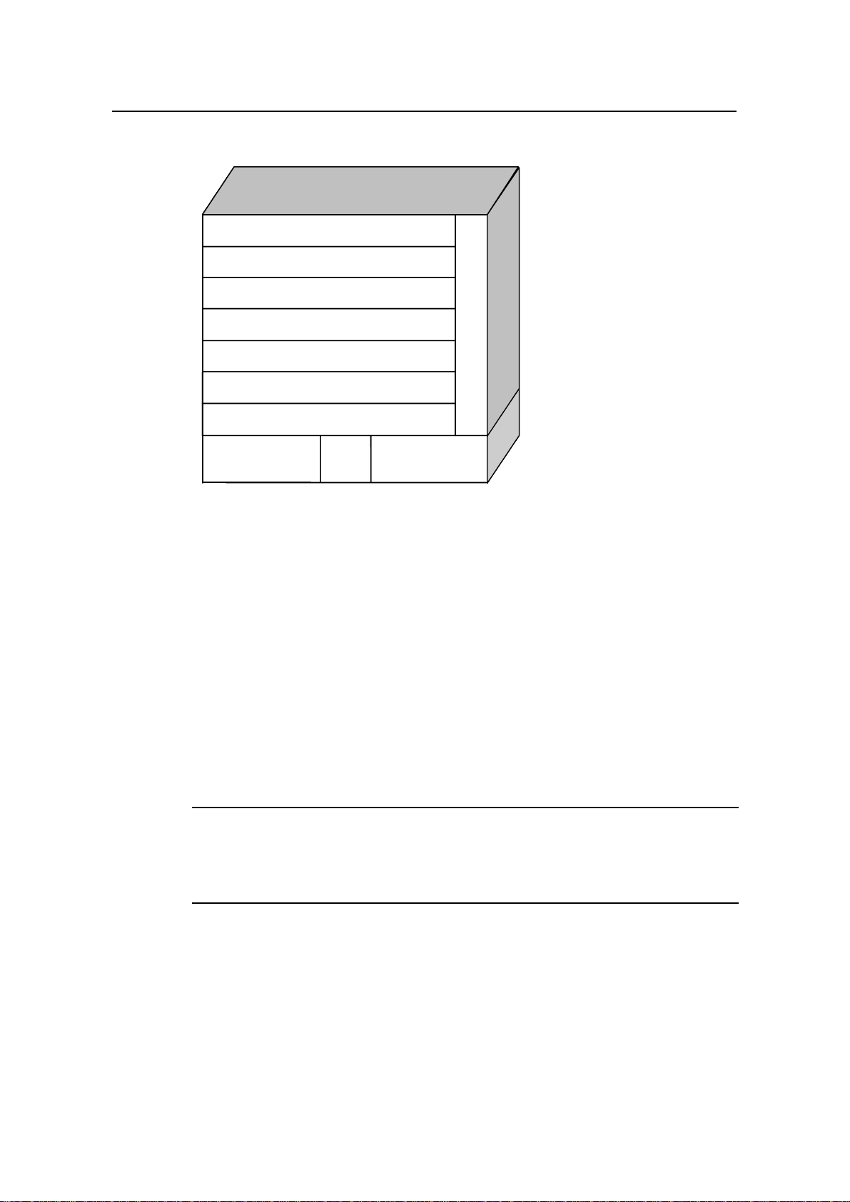
z S9505: provides up to 300 Gbps switching capacity and allows the concurrent
wirespeed forwarding on 240 GE ports, or 20 × 10GE ports, or 240 FE electrical
ports, or 100 FE optical ports.
Figure 1-2 H3C S9505
1-1
Page 8
Installation Manual
H3C S9500 Series Routing Switches Chapter 1 Product Overview
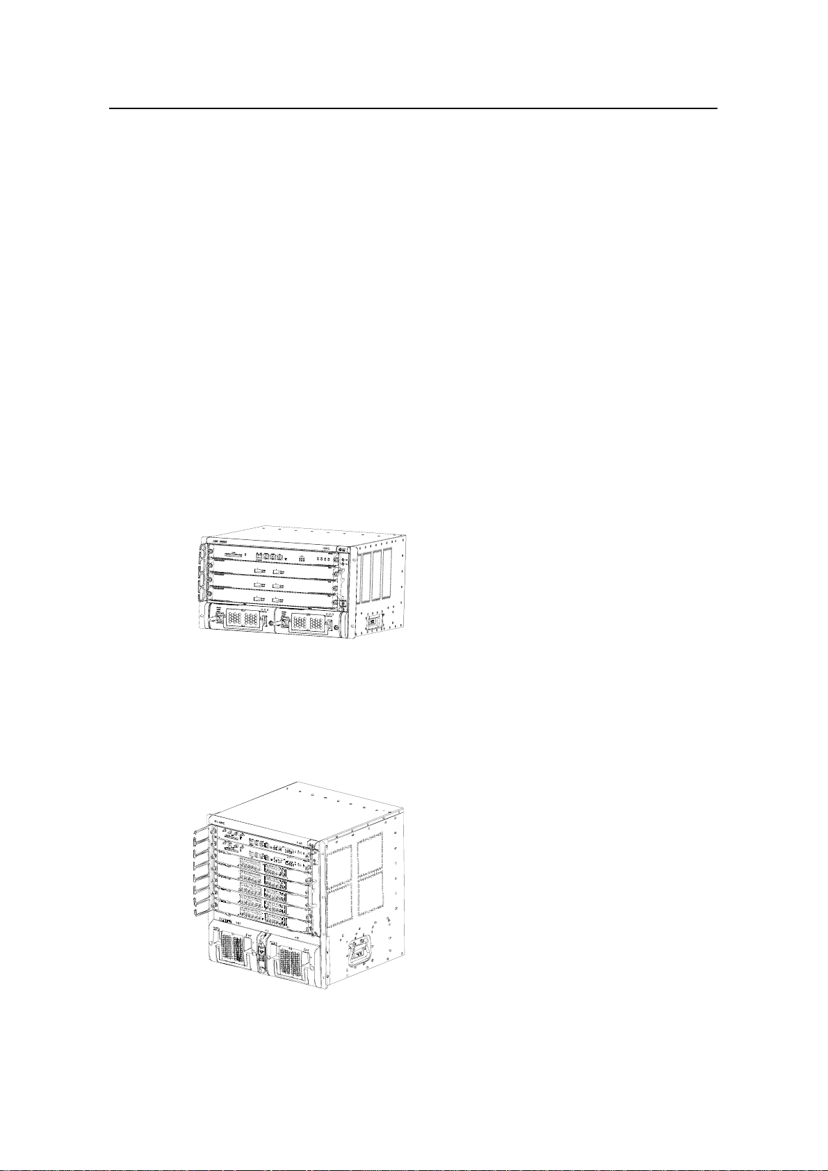
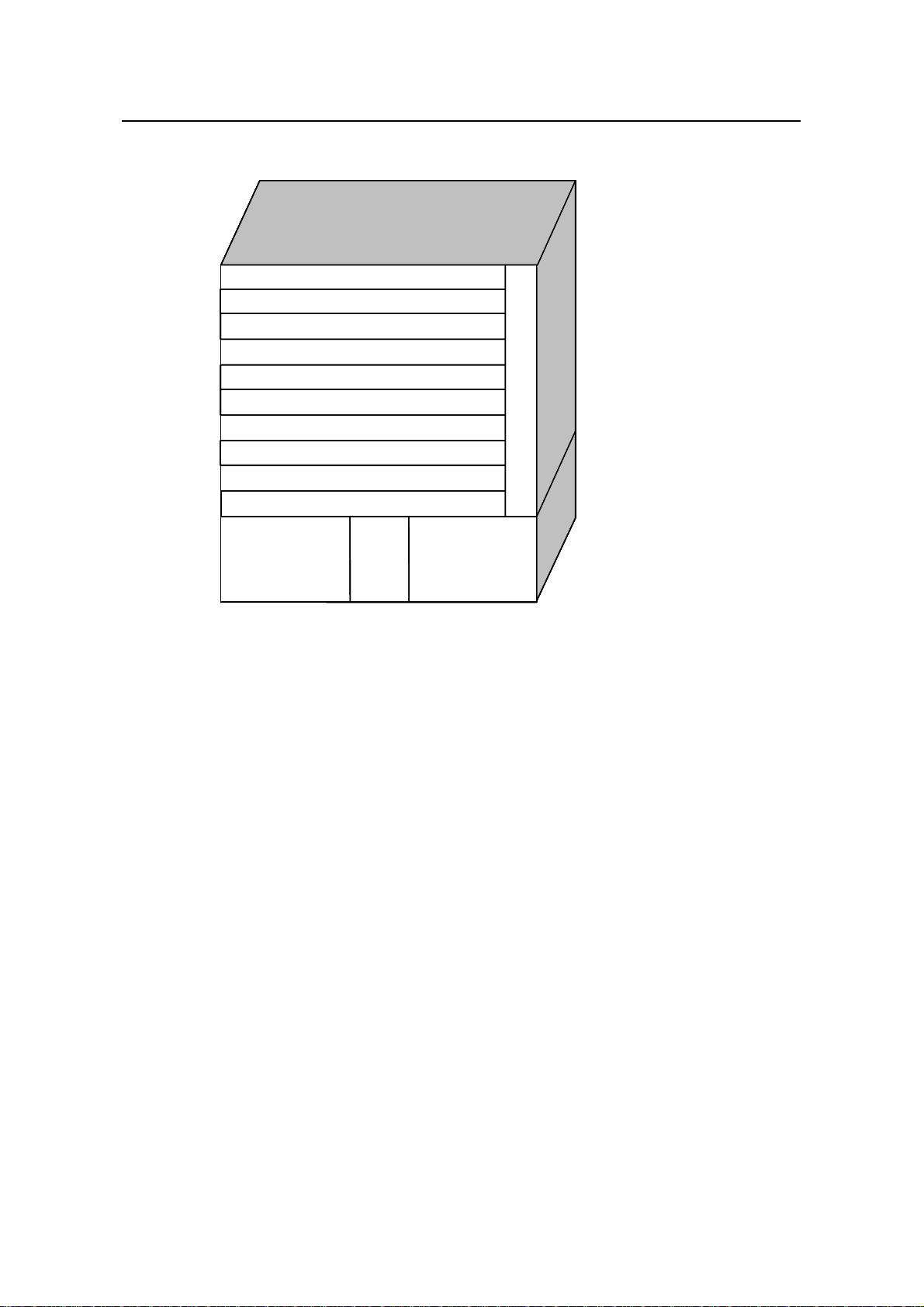
z S9508: provides up to 480 Gbps switching capacity and allows the concurrent
wirespeed forwarding on 384 GE ports, or 32 × 10GE ports, or 384 FE electrical
ports, or 160 FE optical ports.
Figure 1-3 H3C S9508
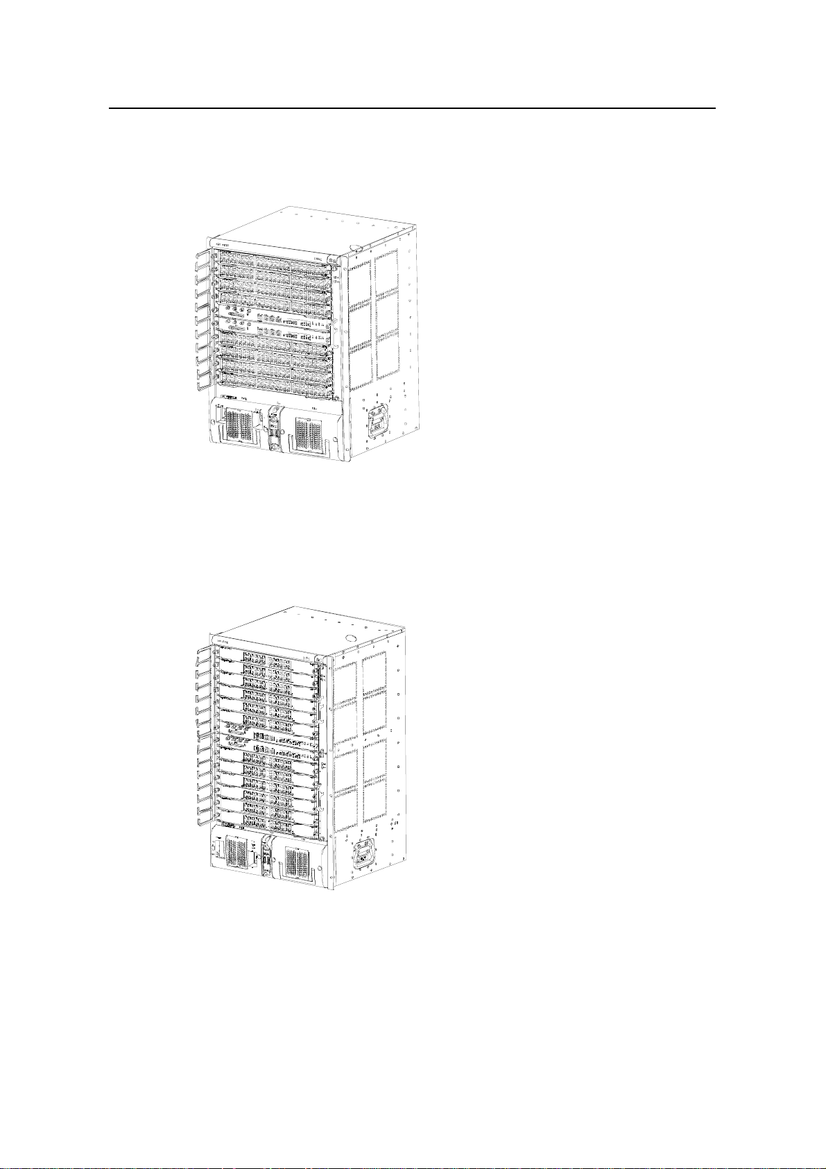
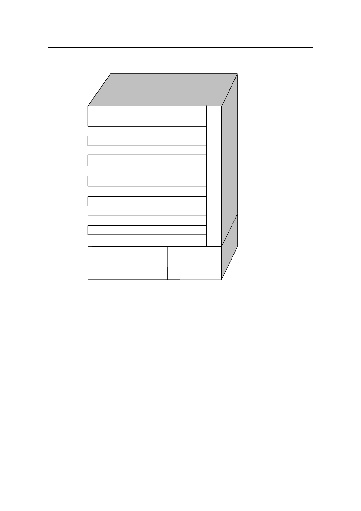
z S9512: provides up to 720 Gbps switching capacity and allows the concurrent
wirespeed forwarding on 576 GE ports, or 48 × 10GE ports, or 576 FE electrical
ports, or 240 FE optical ports.
Figure 1-4 H3C S9512
1.2 General Architecture
The S9500 series use integrated chassis, which can be subdivided into power supply
area, board area, backplane and fan area.
1-2
Page 9
Installation Manual
H3C S9500 Series Routing Switches Chapter 1 Product Overview
1.2.1 Chassis and Slots
I. For S9502
SRPU
SRPU
SRPU
SRPU
SRPU
SRPU
SRPU
SRPU
SRPU
SRPU
交换路由板
交换路由板
交换路由板
交换路由板
交换路由板
交换路由板
交换路由板
交换路由板
交换路由板
交换路由板
交换路由板
交换路由板
交换路由板
交换路由板
交换路由板
交换路由板
交换路由板
交换路由板
交换路由板
交换路由板
SRPU/LPU
SRPU/LPU
SRPU/LPU
SRPU/LPU
SRPU/LPU
SRPU/LPU
SRPU/LPU
SRPU/LPU
SRPU/LPU
SRPU/LPU
交换路由板/接口板
交换路由板/接口板
交换路由板/接口板
交换路由板/接口板
交换路由板/接口板
交换路由板/接口板
交换路由板/接口板
交换路由板/接口板
交换路由板/接口板
交换路由板/接口板
交换路由板/接口板
交换路由板/接口板
交换路由板/接口板
交换路由板/接口板
交换路由板/接口板
交换路由板/接口板
交换路由板/接口板
交换路由板/接口板
交换路由板/接口板
防
防
防
防
防
防
防
防
防
防
防
防
防
防
防
防
防
防
防
防
尘
尘
尘
尘
尘
尘
尘
尘
尘
尘
尘
尘
尘
尘
尘
尘
尘
尘
尘
尘
网
网
网
网
网
网
网
网
网
网
网
网
网
网
网
网
网
网
网
网
AC /DC
AC /DC
AC /DC
AC /DC
AC /DC
AC /DC
AC /DC
AC /DC
AC /DC
AC /DC
AC /DC
AC /DC
AC /DC
AC /DC
AC /DC
AC /DC
AC /DC
AC /DC
AC /DC
AC /DC
AC /DC
AC /DC
AC /DC
AC /DC
AC /DC
AC /DC
AC /DC
AC /DC
AC /DC
AC /DC
AC/DC PSU AC/DC PSU
AC/DC PSU AC/DC PSU
AC/DC PSU AC/DC PSU
AC/DC PSU AC/DC PSU
AC/DC PSU AC/DC PSU
AC/DC PSU AC/DC PSU
AC/DC PSU AC/DC PSU
AC/DC PSU AC/DC PSU
AC/DC PSU AC/DC PSU
AC/DC PSU AC/DC PSU
交换路由板/接口板
LPU
LPU
LPU
LPU
LPU
LPU
LPU
LPU
LPU
LPU
接口板
接口板
接口板
接口板
接口板
接口板
接口板
接口板
接口板
接口板
接口板
接口板
接口板
接口板
接口板
接口板
接口板
接口板
接口板
接口板
接口板
接口板
接口板
接口板
接口板
接口板
接口板
接口板
接口板
接口板
LPU
LPU
LPU
LPU
LPU
LPU
LPU
LPU
LPU
LPU
接口板
接口板
接口板
接口板
接口板
接口板
接口板
接口板
接口板
接口板
接口板
接口板
接口板
接口板
接口板
接口板
接口板
接口板
接口板
接口板
接口板
接口板
接口板
接口板
接口板
接口板
接口板
接口板
接口板
接口板
电源模块
电源模块
电源模块
电源模块
电源模块
电源模块
电源模块
电源模块
电源模块
电源模块
电源模块
电源模块
电源模块
电源模块
电源模块
电源模块
电源模块
电源模块
电源模块
电源模块
电源模块
电源模块
电源模块
电源模块
电源模块
电源模块
电源模块
电源模块
电源模块
电源模块
AC /DC
AC /DC
AC /DC
AC /DC
AC /DC
AC /DC
AC /DC
AC /DC
AC /DC
AC /DC
AC /DC
AC /DC
AC /DC
AC /DC
AC /DC
AC /DC
AC /DC
AC /DC
AC /DC
AC /DC
AC /DC
AC /DC
AC /DC
AC /DC
AC /DC
AC /DC
AC /DC
AC /DC
AC /DC
AC /DC
电源模块
电源模块
电源模块
电源模块
电源模块
电源模块
电源模块
电源模块
电源模块
电源模块
电源模块
电源模块
电源模块
电源模块
电源模块
电源模块
电源模块
电源模块
电源模块
电源模块
电源模块
电源模块
电源模块
电源模块
电源模块
电源模块
电源模块
电源模块
电源模块
电源模块
Figure 1-5 S9502 slots
z The S9502 chassis provides four slots in its board area: from up to down, the first
one accommodates an SRPU (switching and routing processor unit), the second
one accommodates an SRPU or an LPU (line processor unit), and the remaining
two slots accommodate LPU/SPC (service processor card) modules, which you
can select from various available LPUs and SPCs. If an SRPU is contained in the
second slot, the two SRPUs in the first and the second slots can operate in 1+1
redundancy mode. All modules in this area are hot-swappable.
z At the bottom of the chassis is the power area that contains two PSUs (power
supply units). The two PSUs are online-swappable; they can operate in 1+1
redundancy mode. The switch supports both AC and DC power inputs. So you can
select AC/DC PSUs as needed. The S9502 supports PoE, and uses a PoE filter at
the rear of the chassis to import power from an external PoE power supply.
z On the right of the chassis is the fan area that contains a vertical hot-swappable
fan tray. The fan tray draws and exhausts air from left to right.
Fan tray
Fan tray
Fan tray
Fan tray
风
风
风
风
风
风
风
风
风
风
风
风
风
风
风
风
风
风
风
风
风
风
风
风
风
风
风
风
风
风
扇
扇
扇
扇
扇
扇
扇
扇
扇
扇
扇
扇
扇
扇
扇
扇
扇
扇
扇
扇
扇
扇
扇
扇
扇
扇
扇
扇
扇
扇
Note:
The two PSUs are online-swappable, which means you can use one PSU to supply
power to the whole switch while changing the other PSU. But before removing or
inserting a PSU, you must first power off it.
1-3
Page 10
Installation Manual
H3C S9500 Series Routing Switches Chapter 1 Product Overview
II. For S9505
SRPU
SRPU
SRPU
SRPU
LPU
AC or DC power
AC or DC power
LPU
LPU
LPU
LPU
LPU
LPU
LPU
LPU
LPU
PoE
PoE
entry
entry
AC or DC power
AC or DC power
Fan tray
Fan tray
Figure 1-6 S9505 slots
All modules in the cabinet are hot-swappable.
z The S9505 chassis provides seven slots: The top two accommodate SRPU
modules, which are in 1+1 redundancy; the remaining five accommodate LPU
modules and service processor cards, which can be hybrid.
z At the bottom of the chassis is the power supply area that contains one PoE entry
area, two power supply units (PSU) that are online-swappable (which means you
can use one PSU to supply power to the whole switch while changing the other
PSU). The switch can be either AC-powered or DC-powered.
z On the right of the chassis is the fan area that contains only one vertical fan tray.
The fan tray draws air from the left and exhausts on the right.
Note:
The two PSUs are online-swappable. But before removing or inserting a PSU, you must
first power off the PSU.
1-4
Page 11
Installation Manual
H3C S9500 Series Routing Switches Chapter 1 Product Overview
III. For S9508
LPU
LPU
LPU
LPU
LPU
LPU
LPU
LPU
SRPU
SRPU
SRPU
SRPU
LPU
LPU
LPU
LPU
LPU
LPU
LPU
LPU
Fan tray
Fan tray
PoE
AC or DC power
AC or DC power
Figure 1-7 S9508 slots
All modules in the cabinet are hot-swappable.
z The S9508 chassis provides ten slots: The middle two accommodate SRPU
modules, which are in 1+1 redundancy; the remaining eight accommodate LPU
modules and service processor cards, which can be hybrid.
z At the bottom of the chassis is the power supply area that contains the PoE entry
area, two PSUs that are online-swappable. The switch can be either AC-powered
or DC-powered.
z On the right of the chassis is the fan area that contains only one vertical fan tray.
The fan tray draws air from the left and exhausts on the right.
PoE
entry
entry
AC or DC power
AC or DC power
1-5
Page 12
Installation Manual
H3C S9500 Series Routing Switches Chapter 1 Product Overview
IV. For S9512
LPU
LPU
LPU
LPU
LPU
LPU
LPU
LPU
LPU
LPU
LPU
LPU
SRPU
SRPU
SRPU
SRPU
LPU
LPU
LPU
LPU
LPU
LPU
LPU
LPU
LPU
LPU
LPU
LPU
Fan tray 1 Fan tray 2
Fan tray 1 Fan tray 2
AC or DC power
Figure 1-8 S9512 slots
All modules in the cabinet are hot-swappable.
z The S9512 chassis provides 14 slots: The two in the middle accommodate SRPU
modules, which are in 1+1 redundancy; the remaining 12 accommodate LPU
modules and service processor cards, which can be hybrid.
z At the bottom of the chassis is the power supply area that contains the PoE entry
area and two PSUs that are online-swappable. The switch can be either
AC-powered or DC-powered.
z On the right of the chassis is the fan area that contains two vertical fan trays. The
fan trays draw air from the left and exhausts on the right.
1.2.2 Backplane
The backplane of the S9500 series allows high-speed data exchange between an
SRPU module and LPU modules, as well as the exchange of various management and
control signals in the system.
PoE
PoE
entry
entry
AC or DC powerAC or DC power
AC or DC power
1-6
Page 13

Installation Manual
H3C S9500 Series Routing Switches Chapter 1 Product Overview
I. Functions
The backplane mainly functions in
z Providing communication channels for signal exchange between boards
z Providing support for hot-swapping of boards
z Auto-identifying the slots
z Connecting PSUs, achieving distributed power supply for SRPU modules, LPU
modules and PSUs and providing corresponding control channels.
II. Structure
z S9502
It uses a passive backplane, which provides two LPU slots and two SRPU slots or
provides three LPU slots and one SRPU slot, one port for fan tray, and two -48V ports
(one for system power input and one for PoE entry).
z For S9505
It uses a passive backplane, which provides five LPU slots and two SRP slots, one port
for fan tray and two –48V ports (one for system power input and one for PoE entry).
z For S9508
It uses a passive backplane, which provides eight LPU slots and two SRP slots, one
port for fan tray and two –48V ports (one for system power input and one for PoE
entry).
z For S9512
It uses a passive backplane, which provides 12 LPU slots and two SRP slots, one port
for fan tray and two –48V ports (one for system power input and one for PoE entry).
1.2.3 System Power Supply
Note:
z The S9500 series can be AC-powered or DC-powered. You can choose power
supply modules as needed.
z If you want to change power supply type, just insert the power supply module of right
type.
z Power supply modules of the S9500 series are online-swappable.
The S9500 series can be AC-powered or DC-powered. The power supply is at the
bottom of the chassis, with a height of 3U (except S9502 switches). You can insert both
AC and DC power supply modules in the same slot based on your needs. The power
frame is in different compartment from the functional board frame and connected to the
1-7
Page 14
Installation Manual
H3C S9500 Series Routing Switches Chapter 1 Product Overview
latter with cables, which are routed on the chassis back. The power supply is cooled by
built-in fans of the PSU, which draw air into the chassis from the front and exhaust out
of the back.
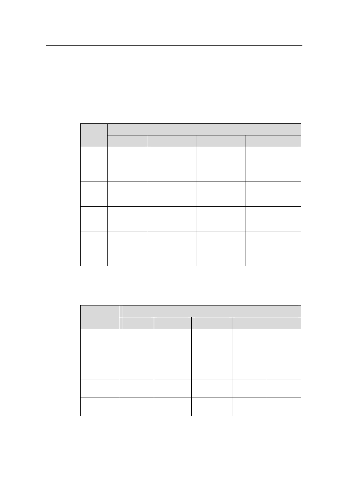
I. Power supply specifications
z AC-input PSU
Table 1-1 Specifications for the AC-input PSU
Item
Specifications
S9502 S9505 S9508 S9512
Rated
voltage
range
Max
voltage
range
100 VAC to
240 VAC,
50/60 Hz
90 VAC to
264 VAC,
50/60Hz
100 VAC to 240
VAC, 50 Hz
90 VAC to 264
VAC, 47 Hz to
63 Hz
Max
input
7.5 A 15 A 15 A 15 A
current
Max
output
600 W 1200 W
power
z DC-input PSU
Table 1-2 Specifications for the DC-input PSU
100 VAC to 120
VAC, 50 Hz
200 VAC to 240
VAC, 50 Hz
90 VAC to 264
VAC, 47 Hz to
63 Hz
1200 W (90 V to
160 V)
2000 W (160 V
to 264 V)
100 to 120 VAC,
50 Hz
200 to 240 VAC,
50 Hz
90 VAC to 264
VAC, 47 Hz to 63
Hz
1200 W (90 V to
160 V)
2000 W (160 V to
264 V)
Item
Rated
voltage
range
Max voltage
range
Max input
current
Max output
power
Specifications
S9502 S9505 S9508 S9512
–60 VDC
to –48
–48 VDC –48 VDC –48 VDC –48 VDC
VDC
–72 VDC
to –36
VDC
–72 VDC to
–36 VDC
–72 VDC to
–36 VDC
–72 VDC
to –36
VDC
–72 VDC
to –36
VDC
12.5 A 25 A 42 A 42 A 25 A
600 W 1200 W 2000 W 2000 W 1200 W
1-8
Page 15
Installation Manual
H3C S9500 Series Routing Switches Chapter 1 Product Overview
1.2.4 PoE Power Supply
The S9500 series support power over Ethernet (PoE). With this feature, a S9500 series
switch equipped with external power supply and PoE-capable cards can deliver 48
VDC to remotely powered devices (PDs, such as IP Phones, WLAN APs and Network
Cameras) through twisted pairs.
z The S9500 series can supply power to remote PDs through the Ethernet electrical
ports on the LPUs. Each LPU can simultaneously supply power to up to 48 PDs at
a distance of up to 100 m (328.1 feet) away.
z Each Ethernet port can deliver up to 15.4 W to its PD.
z Totally, an S9500 series switch can deliver up to 4500 W (220 V)/2250 W (110 V)
power to its PDs. It determines whether to deliver power to the newly detected PD
depending on the power it currently supplied.
I. PoE entry area
On the S9500 series, the PoE entry area is between the two power supply modules.
The PoE entry module is connected with the wiring screw post of the power frame when
supported.
II. External PoE power frame
The following two types of PoE external power supplies are available for the S9500
series:
z PSE4500-A: adopted by S9505/S9508/S9512 switches
z PSE2500-A1: adopted by S9502 switches
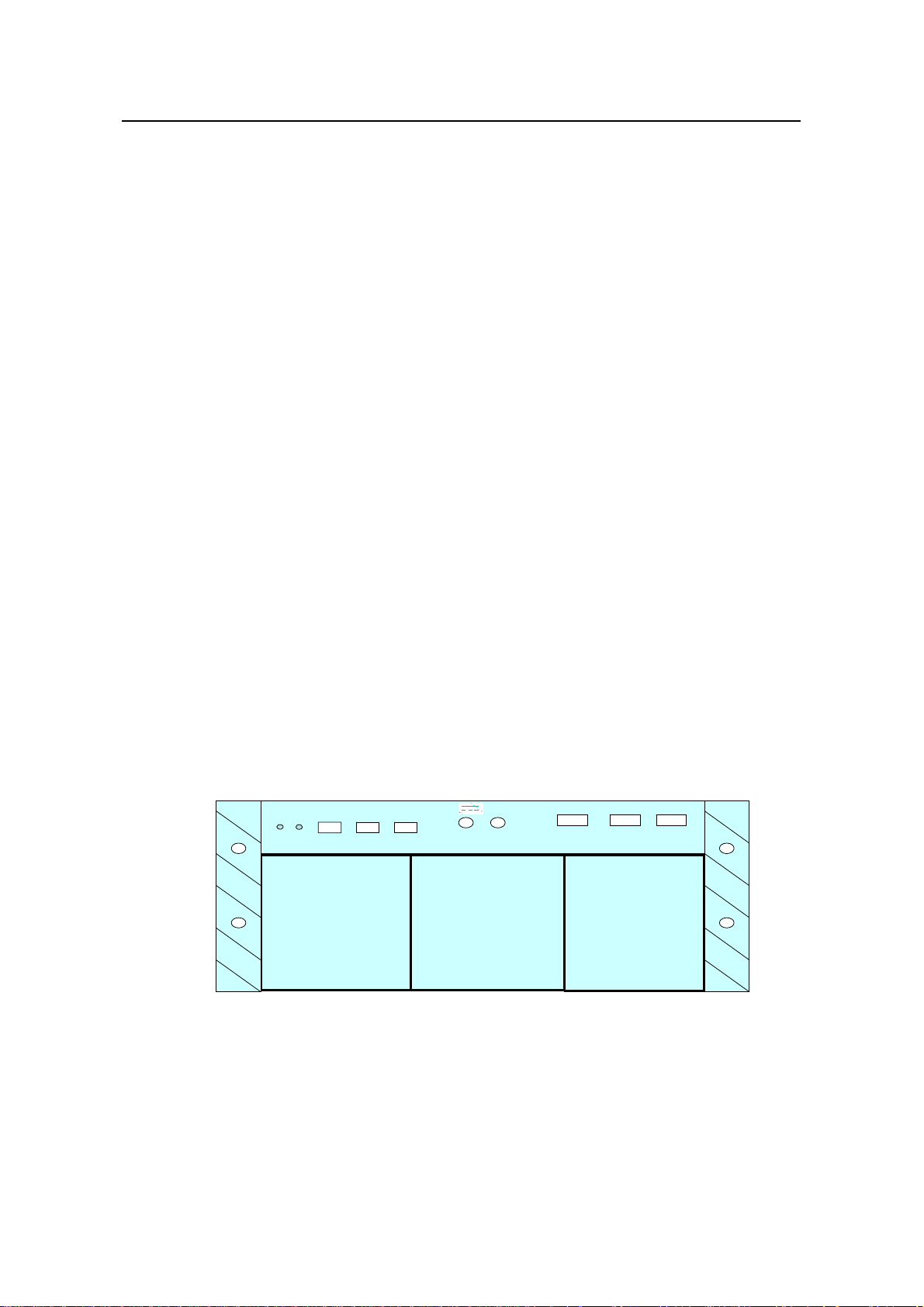
Currently the S9500 series support the PoE power system with three AC inputs and
one DC output. The PoE power frame with three AC inputs is shown
INPUT1 INPUT2 INPUT3
POE Power System PSE4500-A
POE Power System PSE4500-A
RUN ALM RS485-1 RS485-2 RS232
RUN ALM RS485-1 RS485-2 RS232
PS1
PS1
-54V;83.0A
NEG (-) RTN (+)
NEG (-) RTN (+)
This device has more than one power input. Do
This device has more than one power input. Do
disconnect all power inputs to power off this devi ce.
disconnect all power inputs to power off this devi ce.
-54V;83.0A
PS2 PS3
PS2 PS3
INPUT1 INPUT2 INPUT3
Each Input at: ~100-120/200-240V;
Each Input at: ~100-120/200-240V;
50-60Hz; 15.0/15.0A
50-60Hz; 15.0/15.0A
PS3
PS3
Figure 1-9:
Figure 1-9 Three-input PoE power frame
1-9
Page 16
Installation Manual
H3C S9500 Series Routing Switches Chapter 1 Product Overview
Note:
The external PoE power system supports 2+1 redundancy and online-swap.
Dedicated interface module is required for the PoE power supply on switches. On the
S9500 series, it is the GV48 interface module.
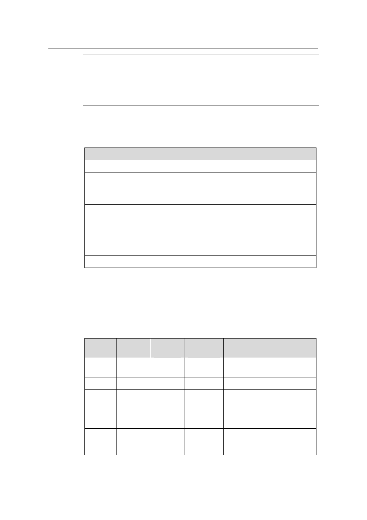
Table 1-3 describes the technical specifications of the external PoE power system.
Table 1-3 Technical specifications of the PoE power system
Item Description
Dimensions (H × W × D) 177 × 486 × 320.5 mm (7.0 × 19.1 × 12.6 in.)
System controller One
Rectifier
Two NP2500UAC (required) + one redundant
NP2500UAC (optional)
Three AC inputs with one manual switch for each
AC distribution assembly
Three-phase AC voltage detection circuit
Input voltage range: 90 VAC to 290 VAC; rated voltage
and current: 250 VAC/20A
DC distribution assembly A single DC output, with max output current of 93A
Max. power consumption 4500 W
PoE power system functions in monitoring and provides an RS232 and two RS485
monitoring interfaces. The system monitor sends the running information of the system
module to SRP through RS232 or RS485 interfaces and displays the alarm by ALM
LED. You can connect cables to the interface from the front or rear of the frame.
Table 1-4 LEDs of PoE power system
LED Color
Normal
status
AC Green ON OFF
Abnormal
status
Causes
There is no AC input or the fuse
is broken.
DC Green ON OFF There is no DC output.
Fault Red OFF ON
RUN Green ON OFF
The fault in the module is
irretrievable.
The power module is not
running or is failed.
There is under- and
ALM Red OFF ON
over-voltage, even no AC
power input, or faulty module.
1-10
Page 17
Installation Manual
H3C S9500 Series Routing Switches Chapter 1 Product Overview
1.2.5 Fan Tray
The S9502 uses eight DC fan units (70 × 70 × 25.4 mm or 2.8 × 2.8 × 1.0 in) in a fan tray
(36 W, and there is only one fan tray in the chassis). The fans operate on 12 VDC
supplied from the fan monitor board.
The S9505 uses four DC fan units (120 × 120 × 25.4 mm or 4.7 × 4.7 × 1.0 in) in a fan
tray (25 W).The fans can be governed in two modes: SRPU-controlled or
temperature-controlled. They operate on –48 VDC supplied from the backplane.
The fan subsystem of the S9508 and S9512 is the same as that of the S9505, except
that the S9508 uses six DC fan units in one fan tray (35 W) and the S9512 uses eight
DC fan units in two fan trays (25 W for each frame, four units in each).
Figure 1-10 Panel of the fan tray for the S9500 series
Table 1-5 LEDs on the faceplate of the fan tray
LED Color Status
RUN
ALM
1.2.6 SRPU Module
The SRPU module is the core of the switch, and mainly functions in
OFF The fan tray is faulty.
Green The fan tray is running normally.
OFF The fan tray is running normally.
Red The fan tray is faulty.
1-11
Page 18
Installation Manual
H3C S9500 Series Routing Switches Chapter 1 Product Overview
z Route calculating and forwarding table maintenance.
z Integrating Crossbar switching fabric to exchange the service between different
boards.
z Providing system configuration and monitoring functions, which allows the system
to upgrade and reset service board software.
The S9500 series support these types of SRPU modules:
z S9502: SRP1M1
z S9505: SRP1N6,SRP1N7
z S9508: SRP1N5,SRP1N7
z S9512: SRP1N4,SRP1N7
I. SRP1N4 module
1) Specifications
The S9512 uses SRP1N4 modules. The following table summarizes the module
specifications.
Table 1-6 SRP1N4 module specifications
Attribute SRP1N4
CPU MPC755
Boot ROM 512 KB
SDRAM 512 MB (expandable to 1 GB)
Dimensions (L × W) 366.7 × 340 mm (14.4 × 13.4 in.)
One Console port, for local configuration management
One AUX port, for remote dialup configuration
management
Port
One 10Base-T/100Base-TX port for system management
and program upgrade
One RS232/485 port, for connecting external PoE power
frame when supported
One hot-swappable CF port
Max. power
consumption
60 W
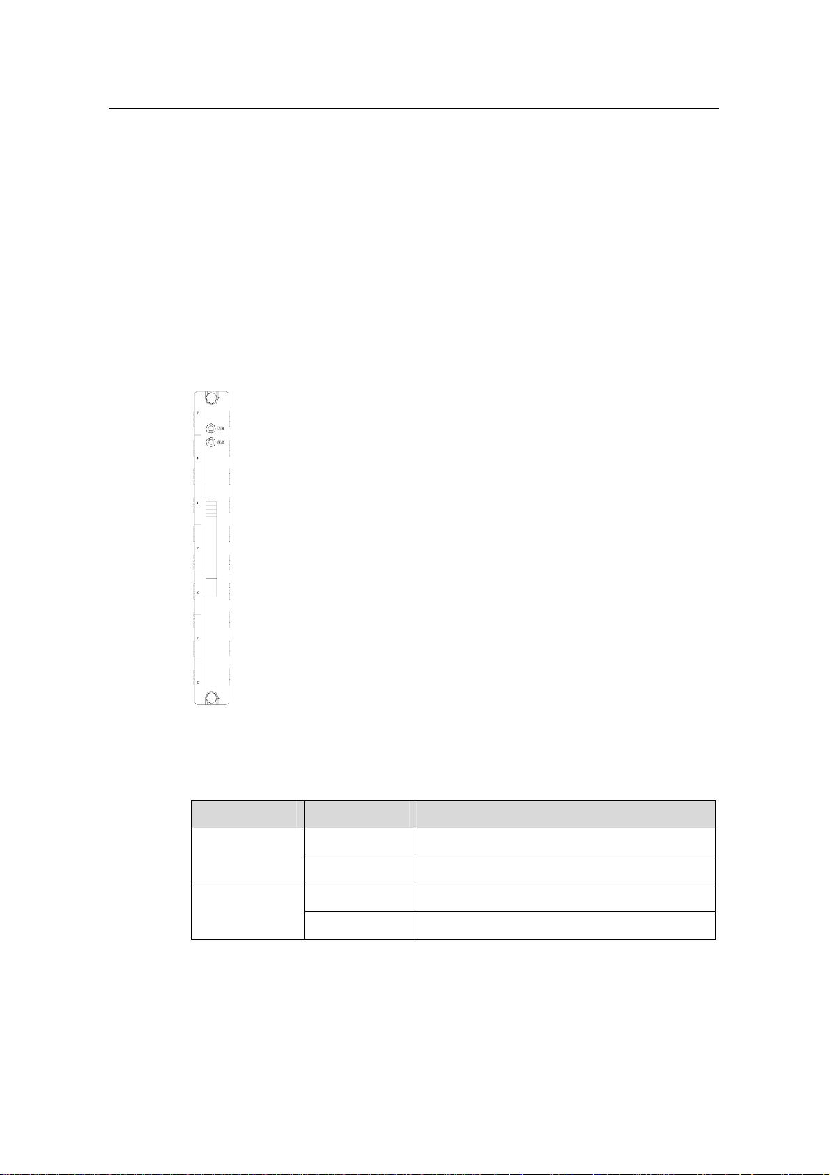
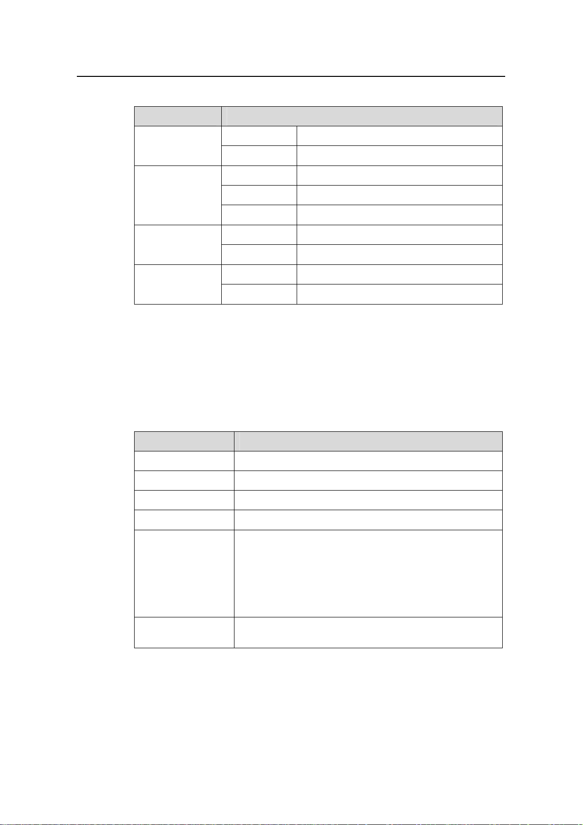
2) SRP1N4 panel
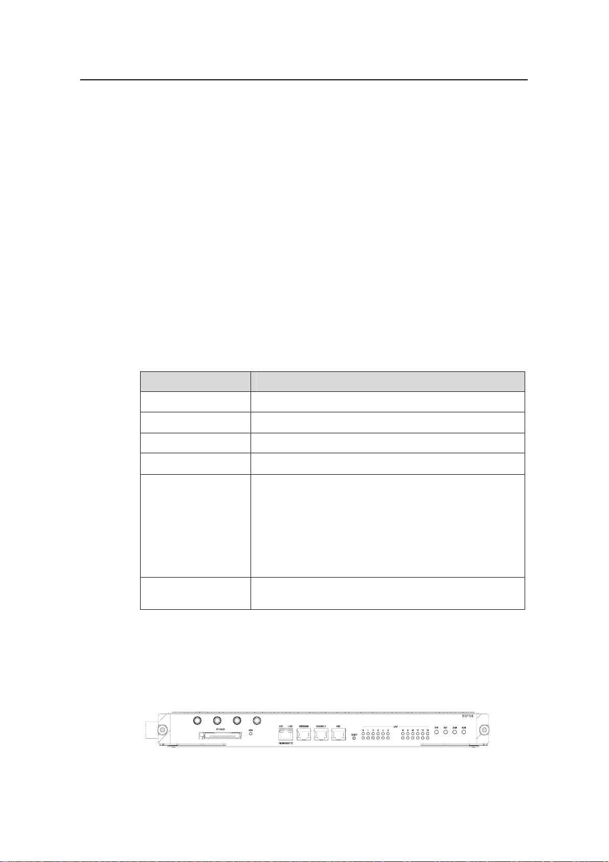
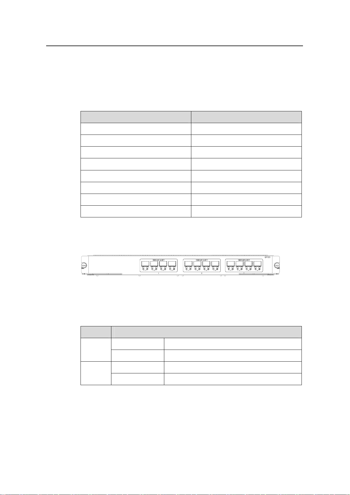
The SRP1N4 module provides CF port, CF LED (CFS), 10Base-T/100Base-TX port,
RS232/485 port, Console port, AUX port, RESET button, LPU status LEDs, SRP1N4
status LEDs (SFS, ACT, ALM, RUN), as shown in
Figure 1-11.
Figure 1-11 SRP1N4 panel
1-12
Page 19
Installation Manual
H3C S9500 Series Routing Switches Chapter 1 Product Overview
3) User ports
z CF port
The SRP1N4 module provides a CF port to accommodate a standard CF card, where
you can save logging information, host version information, alarming and other
diagnostic information and conveniently upgrade software online.
z Management 10Base-T/100Base-TX port
The management 10Base-T/100Base-TX port uses an RJ-45 connector. It can connect
a background terminal for system program loading and debugging, or connect a
network management station for remote system management.
Table 1-7 Management 10Base-T/100Base-TX port specifications
Attribute Description
Connector RJ-45
Number of ports One
Rate
Max. transmission segment
over the selected medium
10 Mbps, half duplex/full duplex
100 Mbps, half duplex/full duplex
100 m (328 ft) over the category-5 twisted pair cable
(crossover cable is required).
Service System program upgrade and network management
The following table describes the status LEDs for the management
10Base-T/100Base-TX port.
Table 1-8 Status LEDs for the management 10Base-T/100Base-TX port
LED Status
OFF No link is present.
LINK
ON A link is present.
OFF No packets are transmitted/received on the port.
ACT
Blinking Packets are being transmitted/received on the port.
z RS232/485 port
The RS232/485 port uses RJ-45 connector, for connecting external PoE power frame
when supported and monitoring its status.
1-13
Page 20
Installation Manual
H3C S9500 Series Routing Switches Chapter 1 Product Overview
Table 1-9 RS232/485 port specifications
Attribute Description
Connector RJ-45
Number of ports One RS 232 port and one RS485 port
Service
The port for monitoring and communication with the external
subsystem, such as external PoE power supply module
z Console port
The Console port uses an RJ-45 connector. It can be connected to a background
terminal for system debugging, maintenance, management, and host software loading.
Table 1-10 Console port specifications
Attribute Description
Connector RJ-45
Standard Asynchronous EIA/TIA-232
Baud rate 9600 bps (default)
Transmission segment
Service
≤ 15 m (49 ft)
Connects a serial port of a local PC and runs terminal
emulation on the PC.
Note:
You can choose your own baud rate for the Console port.
z AUX port
The AUX port uses an RJ-45 connector. The port can serve as a backup port for the
Console port to connect a background terminal, or directly connect a modem device,
for remote system debugging, configuration, maintenance and management.
Table 1-11 AUX port specifications
Attribute Description
Connector RJ-45
Standard Asynchronous EIA/TIA-232
Service
Connects a serial port of a PC (through a Modem pair for a
remote PC) and runs terminal emulation on the PC.
1-14
Page 21
Installation Manual
H3C S9500 Series Routing Switches Chapter 1 Product Overview
4) RESET button
You can press the RESET button on the panel to reset the SRP1N4 module.
5) Status LEDs
z CF status LED
You can learn the operating status of the CF card by reading the CF status LED on the
panel.
Table 1-12 CF status LED
LED Status
The CF card is in position and is idle. You cannot remove
the card.
The CF card is in position and reading/writing data. You
cannot remove the card.
CFS
ON
Blinking
The CF card is out of position or offline (you can force the
OFF
in-position CF card to go offline using the appropriate
background command). You can remove/insert the card.
z Status LEDs for LPU modules
The SRP1N4 module has 12 pairs of LEDs to indicate the operating status of 12 LPU
modules.
Table 1-13 Status LEDs for LPU modules
LED Status
ON The module is faulty.
OFF The module is faulty or out of position.
RUN
Blinking (1s) The module is running normally.
Fast blinking (125
ms)
The module is booting or not registered
successfully.
ALM
ON The module has alarms.
OFF The module has no alarms or is out of position.
0~5, 8~13 Indicate slots 0 through 5 and slots 8 through 13
z Status LEDs for the SRP1N4 module
You can learn the operating status of SRP1N4 module by reading the SFS, ACT, ALM
and RUN LEDs on it. The following table gives a summary of the four LEDs.
1-15
Page 22
Installation Manual
H3C S9500 Series Routing Switches Chapter 1 Product Overview
Table 1-14 Status LEDs for the SRP1N4 module
SRP1N4 LED Status
SFS
ON The switching fabric unit is active.
OFF The switching fabric unit is standby.
Green The SRP1N4 module is faulty.
RUN
OFF The SRP1N4 module is faulty.
Green blinking The SRP1N4 module runs normally.
Red The SRP1N4 module has alarms.
ALM
OFF
Green The SRP1N4 module is active.
The SRP1N4 module has no alarms.
ACT
OFF
The SRP1N4 module is standby.
II. SRP1N5 module
1) Specifications
The S9508 uses SRP1N5 modules. The following table summarizes the board
specifications.
Table 1-15 SRP1N5 module specifications
Attribute SRP1N5
CPU MPC755
Boot ROM 512 KB
SDRAM 512 MB (expandable to 1 GB)
Dimensions (L × W) 366.7 × 340 mm (14.4 × 13.4 in.)
One Console port, for local configuration management
One AUX port, for remote dialup configuration management
One 10Base-T/100Base-TX port for system management
Port
and program upgrade
One RS232/485 port, for connecting external PoE power
frame when supported
One hot-swappable CF port
Max. power
consumption
60 W
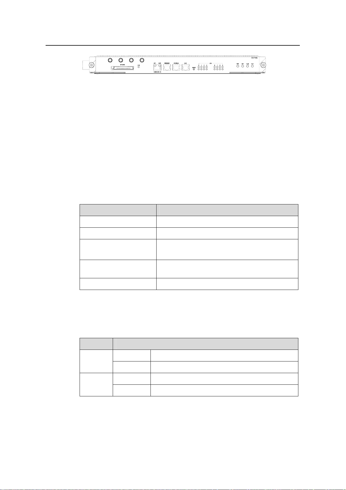
2) SRP1N5 panel
The SRP1N5 module provides CF port, CF LED (CFS), 10Base-T/100Base-TX port,
RS232/485 port, Console port, AUX port, RESET button, LPU status LEDs, SRP1N5
status LEDs (SFS, ACT, ALM, RUN), as shown in
Figure 1-12.
1-16
Page 23
Installation Manual
H3C S9500 Series Routing Switches Chapter 1 Product Overview
Figure 1-12 SRP1N5 panel
3) User ports
z CF port
The SRP1N5 module provides a CF port to accommodate a standard CF card, where
you can save logging information, host version information, alarming and other
diagnostic information and conveniently upgrade software online.
z Management 10Base-T/100Base-TX port
The management 10Base-T/100Base-TX port uses an RJ-45 connector. It can connect
a background terminal for system program loading and debugging, or connect a
network management station for remote system management.
Table 1-16 Management 10Base-T/100Base-TX port specifications
Attribute Description
Connector RJ-45
Number of ports One
Rate
Max. transmission segment
over the selected medium
10 Mbps, half duplex/full duplex
100 Mbps, half duplex/full duplex
100 m (328 ft) over the category-5 twisted pair cable
(crossover cable is required.)
Service System program upgrade and network management
The following table describes the status LEDs for the management
10Base-T/100Base-TX port.
Table 1-17 Status LEDs for the management 10Base-T/100Base-TX port
LED Status
OFF No link is present.
LINK
Green A link is present.
OFF No packets are transmitted/received on the port.
ACT
Blinking Packets are being transmitted/received on the port.
z RS232/485 port
The RS232/485 port uses RJ-45 connector, for connecting external PoE power frame
when supported and monitoring its status.
1-17
Page 24

Installation Manual
H3C S9500 Series Routing Switches Chapter 1 Product Overview
Table 1-18 RS232/485 port specifications
Attribute Description
Connector RJ-45
Number of ports One RS 232 port and one RS485 port
Service
The port for monitoring and communication with the external
subsystem, such as external PoE power supply module
z Console port
The Console port uses an RJ-45 connector. It can be connected to a background
terminal for system debugging, maintenance, management, and host software loading.
Table 1-19 Console port specifications
Attribute Description
Connector RJ-45
Standard Asynchronous EIA/TIA-232
Baud rate 9600 bps (default)
Transmission distance
Service
≤ 15 m (49 ft)
Connects a serial port of a local PC and runs terminal
emulation on the PC.
Note:
You can choose your own baud rate for the Console port.
z AUX port
The AUX port uses an RJ-45 connector. The port can serve as a backup port for the
Console port to connect a background terminal, or directly connect a modem device,
for remote system debugging, configuration, maintenance and management.
Table 1-20 AUX port specifications
Attribute Description
Connector RJ-45
Standard Asynchronous EIA/TIA-232
Service
Connects a serial port of a PC (through a Modem pair for a
remote PC) and runs terminal emulation on the PC.
1-18
Page 25
Installation Manual
H3C S9500 Series Routing Switches Chapter 1 Product Overview
4) RESET button
You can press the RESET button on the panel to reset the SRP1N5 module.
5) Status LEDs
z CF status LED
You can check operating status of the CF card by reading the CF status LED on the
panel.
Table 1-21 CF status LED
LED Status
The CF card is in position and is idle. You cannot remove the
card.
The CF card is in position and reading/writing data. You
cannot remove the card.
CFS
ON
Blinking
The CF card is out of position or offline (you can force the
OFF
in-position CF card to go offline using the appropriate
background command). You can remove/insert the card.
z Status LEDs for LPU modules
The SRP1N5 module has eight pairs of LEDs to indicate the operating status of eight
LPU modules.
Table 1-22 Status LEDs for LPU modules
LED Status
ON The module is faulty.
OFF The module is faulty or out of position.
RUN
Blinking (1s) The module is running normally.
Fast blinking
(125ms)
The module is booting or not registered
successfully.
ALM
ON The module has alarms.
OFF The module has no alarms or is out of position.
0~3, 6~9 Indicate slots 0 through 3 and slots 6 through 9
z Status LEDs for the SRP1N5 module
You can learn the operating status of SRP1N5 module by reading the SFS, ACT, ALM
and RUN LEDs on it. The following table gives a summary of the four LEDs.
1-19
Page 26

Installation Manual
H3C S9500 Series Routing Switches Chapter 1 Product Overview
Table 1-23 Status LEDs for the SRP1N5 module
SRP1N5 LED Status
SFS
ON The switching fabric unit is active.
OFF The switching fabric unit is standby.
Green The SRP1N5 module is faulty.
RUN
OFF The SRP1N5 module is faulty.
Green blinking The SRP1N5 module runs normally.
Red The SRP1N5 module has alarms.
ALM
OFF
Green The SRP1N5 module is active.
The SRP1N5 module has no alarms.
ACT
OFF
The SRP1N5 module is standby.
III. SRP1N6 module
1) Specifications
The S9505 uses SRP1N6 modules. The following table summarizes the board
specifications.
Table 1-24 SRP1N6 module specifications
Attribute SRP1N6
CPU MPC755
Boot ROM 512 KB
SDRAM 512 MB (expandable to 1 GB)
Dimensions (L × W) 366.7 × 340 mm (14.4 × 13.4 in.)
One Console port, for local configuration management
One AUX port, for remote dialup configuration
management
Port
One 10Base-T/100Base-TX port for system management
and program upgrade
One RS232/485 port, for connecting external PoE power
frame when supported
One hot-swappable CF port
Max. power
consumption
60 W
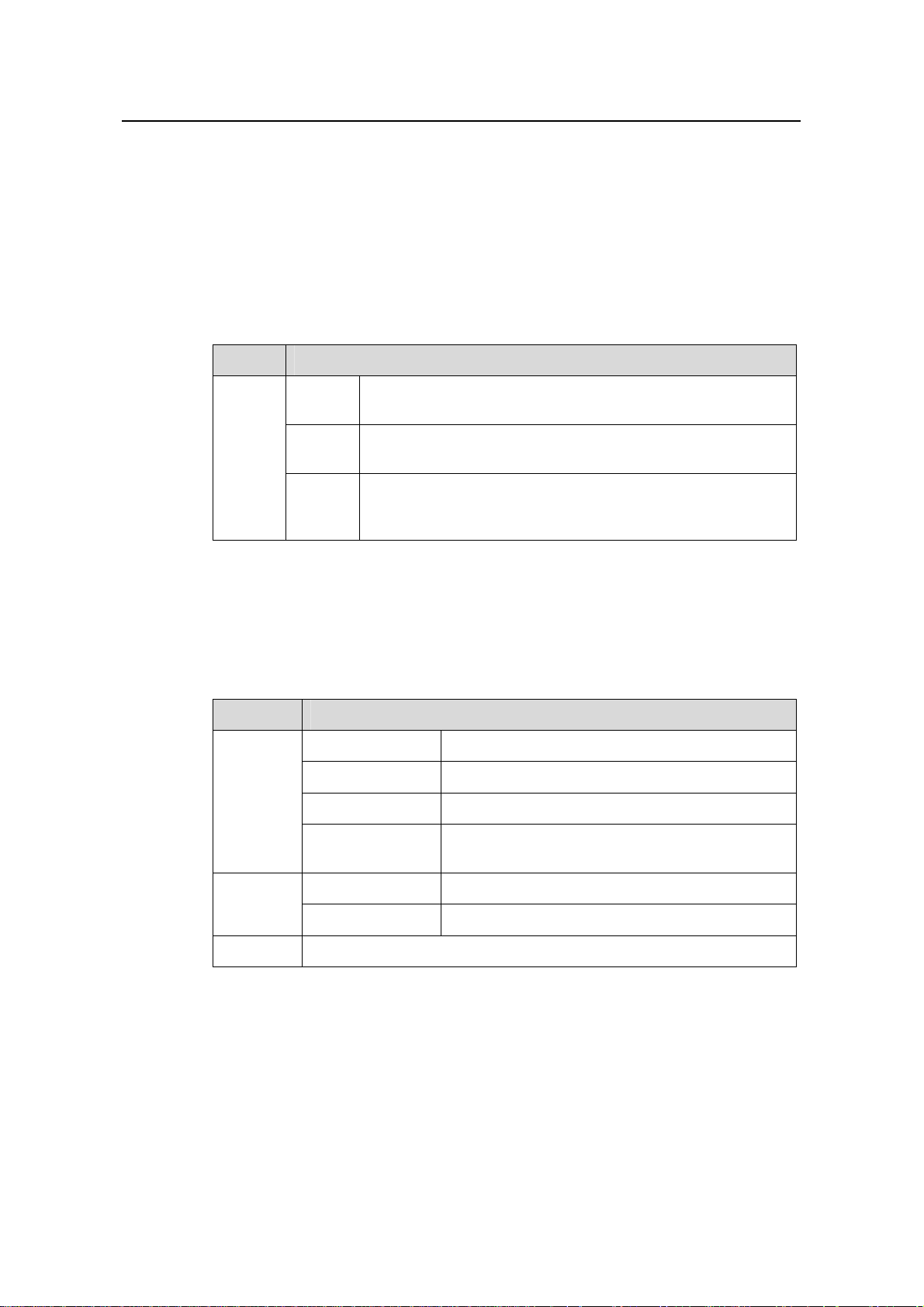
2) SRP1N6panel
1-20
Page 27
Installation Manual
H3C S9500 Series Routing Switches Chapter 1 Product Overview
The SRP1N6 module provides CF port, CF LED (CFS), 10Base-T/100Base-TX port,
RS232/485 port, Console port, AUX port, RESET button, LPU status LEDs, SRP1N6
status LEDs (SFS, ACT, ALM, RUN), as shown in
Figure 1-13.
Figure 1-13 SRP1N6 panel
3) User ports
z CF port
The SRP1N6 module provides a CF port to accommodate a standard CF card, where
you can save logging information, host version information, alarming and other
diagnostic information and conveniently upgrade software online.
z Management 10Base-T/100Base-TX port
The management 10Base-T/100Base-TX port uses an RJ-45 connector. It can connect
a background terminal for system program loading and debugging, or connect a
network management station for remote system management.
Table 1-25 Management 10Base-T/100Base-TX port specifications
Attribute Description
Connector RJ-45
Number of ports One
Rate
Max. transmission segment
over the selected medium
Service
10 Mbps, half duplex/full duplex
100 Mbps, half duplex/full duplex
100 m (328 ft) over the category-5 twisted pair
cable (crossover cable is required.)
System program upgrade and network
management
The following table describes the status LEDs for the management
10Base-T/100Base-TX port.
1-21
Page 28
Installation Manual
H3C S9500 Series Routing Switches Chapter 1 Product Overview
Table 1-26 Status LEDs for the management 10Base-T/100Base-TX port
LED Status
LINK
OFF No link is present.
Green A link is present.
OFF No packets are transmitted/received on the port.
ACT
Orange blinking
Packets are being transmitted/received on the
port.
z RS232/485 port
The RS232/485 port uses RJ-45 connector, for connecting external PoE power frame
when supported and monitoring its status.
Table 1-27 RS232/485 port specifications
Attribute Description
Connector RJ-45
Number of ports One RS 232 port and one RS485 port
Service
The port for monitoring and communication with the external
subsystem, such as external PoE power supply module
z Console port
The Console port uses an RJ-45 connector. It can be connected to a background
terminal for system debugging, maintenance, management, and host software loading.
Table 1-28 Console port specifications
Attribute Description
Connector RJ-45
Standard Asynchronous EIA/TIA-232
Baud rate 9600 bps (default)
Transmission distance
Service
≤ 15 m (49 ft)
Connects a serial port of a local PC and runs terminal
emulation on the PC.
Note:
You can choose your own baud rate for the Console port.
1-22
Page 29
Installation Manual
H3C S9500 Series Routing Switches Chapter 1 Product Overview
z AUX port
The AUX port uses an RJ-45 connector. The port can serve as a backup port for the
Console port to connect a background terminal, or directly connect a modem device,
for remote system debugging, configuration, maintenance and management.
Table 1-29 AUX port specifications
Attribute Description
Connector RJ-45
Standard Asynchronous EIA/TIA-232
Service
Connects a serial port of a PC (through a Modem pair for a
remote PC) and runs terminal emulation on the PC.
4) RESET button
You can press the RESET button on the panel to reset the SRP1N6 module.
5) Status LEDs
z CF status LED
You can check operating status of the CF card by reading the CF status LED on the
panel.
Table 1-30 CF status LED
LED Status
The CF card is in position and is idle. You cannot remove
the card.
The CF card is in position and reading/writing data. You
cannot remove the card.
CFS
ON
Blinking
The CF card is out of position or offline (you can force the
OFF
in-position CF card to go offline using the appropriate
background command). You can remove/insert the card.
z Status LEDs for LPU modules
The SRP1N6 module has five pairs of LEDs to indicate the operating status of five LPU
modules.
1-23
Page 30
Installation Manual
H3C S9500 Series Routing Switches Chapter 1 Product Overview
Table 1-31 Status LEDs for LPU modules
LED Status
ON The module is faulty.
OFF The module is faulty or out of position.
RUN
Blinking (1s) The module is running normally.
Fast blinking
(125ms)
The module is booting or not registered
successfully.
ON The module has alarms.
ALM
OFF The module has no alarms or is out of position.
2~6 Indicate slots 2 through 6
z Status LEDs for the SRP1N6 module
You can learn the operating status of SRP1N6 module by reading the SFS, ACT, ALM
and RUN LEDs on it. The following table gives a summary of the four LEDs.
Table 1-32 Status LEDs for the SRP1N6 module
SRP1N6 LED Status
ON The switching fabric unit is active.
SFS
OFF The switching fabric unit is standby.
Green The SRP1N6 module is faulty.
RUN
OFF The SRP1N6 module is faulty.
Green blinking The SRP1N6 module runs normally.
Red The SRP1N6 module has alarms.
ALM
OFF
Green The SRP1N6 module is active.
The SRP1N6 module has no alarms.
ACT
OFF
The SRP1N6 module is standby.
IV. SRP1N7 module
1) Specifications
The S9512, 9508 and 9505 can use SRP1N7 modules, which integrate clock modules
in them. The following table summarizes the specifications.
1-24
Page 31

Installation Manual
H3C S9500 Series Routing Switches Chapter 1 Product Overview
Table 1-33 SRP1N7 module specifications
Attribute SRP1N7
CPU MPC755
Boot ROM 512KB
SDRAM 1GB
Dimensions (L × W) 366.7 × 340 mm (14.4 × 13.4 in.)
One Console port, for local configuration management
One AUX port, for remote dialup configuration
management
One 10Base-T/100Base-TX port for system
Port
management and program upgrade
One RS232/485 port, for connecting external PoE
power frame when supported
One hot-swappable CF port
Two SMB coaxial clock ports
Max. power consumption 70 W
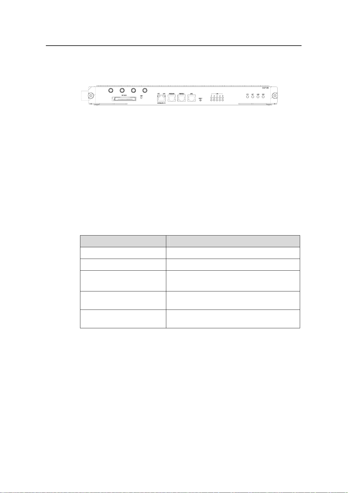
2) SRP1N7 panel
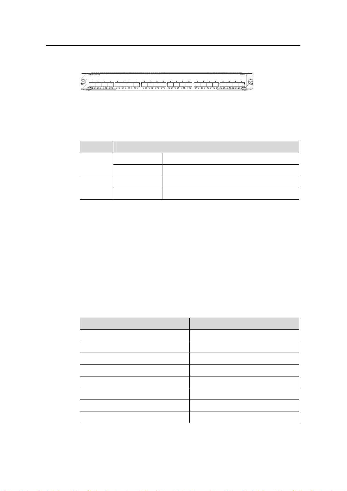
The SRP1N7 module provides SMB coaxial clock ports, CF card, CF LED (CFS), 10
Base-T/100Base-TX port, RS232/485 port, Console port, AUX port, RESET button,
LPU status LEDs, SRP1N7 status LEDs (SFS, ACT, ALM, RUN), as shown in
.
1-14
Figure
Figure 1-14 SRP1N7 panel
3) User ports
z SMB coaxial clock port
The two SMB coaxial clock ports are used as the external benchmark input for internal
clock modules or the clock benchmark for external devices. The port rate/frequency is
2.048 Mbps or 2.048 MHz. You can manually configure the ports through the DIP switch
on the clock module.
z CF port
The SRP1N7 module provides a CF port to accommodate a standard CF card, where
you can save logging information, host version information, alarming and other
diagnostic information and conveniently upgrade software online.
z Management 10Base-T/100Base-TX port
1-25
Page 32

Installation Manual
H3C S9500 Series Routing Switches Chapter 1 Product Overview
The management 10Base-T/100Base-TX port uses an RJ-45 connector. It can connect
a background terminal for system program loading and debugging, or connect a
network management station for remote system management.
Table 1-34 Management 10Base-T/100Base-TX port specifications
Attribute Description
Connector RJ-45
Number of ports One
Rate
Max. transmission distance
over the selected medium
10 Mbps, half duplex/full duplex
100 Mbps, half duplex/full duplex
100 m (328 ft) over the category-5 twisted pair cable
(crossover cable is required.)
Service System program upgrade and network management
The following table describes the status LEDs for the management
10Base-T/100Base-TX port.
Table 1-35 Status LEDs for the management 10Base-T/100Base-TX port
LED Status
OFF No link is present.
LINK
Green A link is present.
OFF No packets are transmitted/received on the port.
ACT
Orange blinking Packets are being transmitted/received on the port.
z RS232/485 port
The RS232/485 port uses RJ-45 connector, for connecting external PoE power frame
when supported and monitoring its status.
Table 1-36 RS232/485 port specifications
Attribute Description
Connector RJ-45
Number of ports One RS 232 port and one RS485 port
Service
The port for monitoring and communication with the external
subsystem, such as external PoE power supply module
z Console port
1-26
Page 33

Installation Manual
H3C S9500 Series Routing Switches Chapter 1 Product Overview
The Console port uses an RJ-45 connector. It can be connected to a background
terminal for system debugging, maintenance, management, and host software loading.
Table 1-37 Console port specifications
Attribute Description
Connector RJ-45
Standard Asynchronous EIA/TIA-232
Baud rate 9600 bps (default)
Transmission
distance
Service
≤ 15 m (49 ft)
Connects a serial port of a local PC and runs terminal
emulation on the PC.
Note:
You can choose your own baud rate for the Console port.
z AUX port
The AUX port uses an RJ-45 connector. The port can serve as a backup port for the
Console port to connect a background terminal, or directly connect a modem device,
for remote system debugging, configuration, maintenance and management.
Table 1-38 AUX port specifications
Attribute Description
Connector RJ-45
Standard Asynchronous EIA/TIA-232
Service
Connects a serial port of a PC (through a Modem pair for a
remote PC) and runs terminal emulation on the PC.
4) RESET button
You can press the RESET button on the panel to reset the SRP1N7 module.
5) Status LEDs
z CF status LED
You can check operating status of the CF card by reading the CF status LED on the
panel. Fore more details about the LEDs, see
z Status LEDs for LPU modules
1-27
Table 1-12
Page 34

Installation Manual
H3C S9500 Series Routing Switches Chapter 1 Product Overview
The SRP1N7 module has 12 pairs of LEDs to indicate the operating status of 12 LPU
modules. Fore more details about the LEDs, see
z Status LEDs for the SRP1N7 module
Table 1-13.
You can learn the operating status of SRP1N7 module by reading the SFS, ACT, ALM
and RUN LEDs on it. Fore more details about the LEDs, see
Table 1-14.
V. SRP1M1 module
1) Specifications
The S9502 uses SRP1M1 modules. The following table summarizes the module
specifications.
Table 1-39 SRP1M1 module specifications
Attribute SRP1M1
CPU MPC755
BootROM 512 KB
SDRAM 512 MB (expandable to 1 GB)
Dimensions (W x D)
366.7 × 340 mm (14.4 × 13.4 in)
One Console port, for local configuration management
One AUX port, for remote dialup configuration
management
One 10Base-T/100Base-TX port, for software upgrade
and network management
Port
One RS232/485 port, for connecting the external PoE
power frame when using PoE function; The RS485 port
supports the cascade connection of PoE power frame and
NEPS3500-AB when using PoE function and
NEPS3500-AB.
One hot-swappable CF port
Max power
consumption
60 W
2) Panel
The SRP1M1 module provides a CF port and CF LED (CFS), a 10Base-T/100Base-TX
port, RS232/485 port, Console port and AUX port, a RESET button, LPU status LEDs,
and SRP1M1 status LEDs (SFS, ACT, ALM, and RUN), as shown in
Figure 1-15.
Figure 1-15 SRP1M1 panel
1-28
Page 35

Installation Manual
H3C S9500 Series Routing Switches Chapter 1 Product Overview
3) User ports
Refer to “
User ports” in "SRP1N4 module".
4) RESET button
You can press the RESET button on the panel to reset the SRP1M1 module.
5) Status LEDs
z CF status LED
You can check the operating status of the CF card by reading the CF status LED on the
panel. For more details about the LED, refer to
z Status LEDs for LPU modules
Table 1-12.
The SRP1M1 module has three pairs of LEDs to indicate the operating status of the
three LPU modules.
Table 1-40 Status LEDs for LPU modules
LED Status
RUN
ON
OFF
Blinking (1s)
The module has failed.
The module has failed or is not present.
The module is operating normally.
When the module is starting up, the RUN
Fast blinking
(125ms)
LED is steady on or fast blinking.
Continuous fast blinking status indicates the
module registration fails.
ALM
1~3 Indicate slots 1 through 3
z Status LEDs for the SRP1M1 module
You can learn the operating status of the SRP1M1 module by reading the SFS, ACT,
ALM and RUN LEDs on its panel. For more details, refer to
1.2.7 LPU Modules
These types of LPU modules are available on the S9500 series:
OFF
ON
There are no alarms on the module or the
module is not present.
There are alarms on the module.
Table 1-14.
1-29
Page 36

Installation Manual
H3C S9500 Series Routing Switches Chapter 1 Product Overview
Table 1-41 LPU modules supported on the S9500 series
LPU User interface
XP2
XP4
XK1
GP12
GP24
FP20
F32G
GT24
GV48
FT48
P4G8
SP4
UP1
2 × 10GEBase-R XFP/LC/10GEBase-W XFP/LC optical ports
4 × 10GE XFP/LC optical ports (1:2 convergence)
1 × 10GE XENPAK/SC port
12 × 1000 Mbps SFP/LC optical ports
24 × 1000 Mbps SFP/LC optical ports
20 × 100 Mbps SFP/LC optical ports
4 × 1000 Mbps SFP/LC optical ports and 32 × 10/100 Mbps
auto-sensing RJ-45 ports
24 × 10/100/1000 Mbps auto-sensing RJ-45 electrical ports
48 × 10/100/1000 Mbps auto-sensing RJ-45 electrical ports
(PoE-supported)
48 × 10/100 Mbps auto-sensing electrical ports
8 × 1000 Mbps SFP/LC optical ports and 4 × 155Mbps SFP/LC
POS optical ports
4 × OC-48c SFP/LC POS optical ports
1 × OC-192c XFP/LC POS optical port
1.2.8 Service Processor Cards
The service processor card is designed specially for high-speed processing of a certain
service, which covers partial or no functions of LPU modules.
The S9500 series support these types of service processor cards:
z NAT service processor card (LSB1NATB0): No external port available.
z VPLS service processor card (LSB1VPNB0): No external port available.
I. NAT service processor card
1) Technical specifications
The NAT service processor card provides no external port.
Table 1-42 Technical specifications of the NAT service processor card
Attribute NAT
CPU MPC755
Boot ROM 512 KB
1-30
Page 37

Installation Manual
H3C S9500 Series Routing Switches Chapter 1 Product Overview
Attribute NAT
SDRAM 512 MB
Dimensions (L × W) 366.7 × 340 mm
2) Front and rear panels
Figure 1-16 Front panel of the NAT service processor card
Figure 1-17 Rear panel of the NAT service processor card
II. VPLS service processor card
1) Technical specifications
The VPLS service processor card provides no external port.
Table 1-43 Technical specifications of the VPLS service processor card
Attribute VPN
CPU MPC755
Boot ROM 512 KB
SDRAM 512 MB
Dimensions (L × W) 366.7 × 340mm (14.4 × 13.4 in)
2) Front and rear panels
Figure 1-18 Front panel of the VPLS service processor card
Figure 1-19 Rear panel of the VPLS service processor card
1-31
Page 38

Installation Manual
H3C S9500 Series Routing Switches Chapter 1 Product Overview
1.2.9 System Specifications
The following table summarizes the physical specifications of the S9500 series.
Table 1-44 Technical specifications of the S9500 series
Item S9502 S9505 S9508 S9512
Dimensions
(H × W × D,
in mm)
Weight (full
load)
Max power
consumption
Switching
capacity
Number of
VLANs
MAC
address
table size
Forwarding
table entries
Number of
SRP slots
264 × 436 × 442
mm (10.4 × 17.2
× 17.4 in)
≤ 40 kg (88.2 lb)
486 × 436 ×
450 mm (19.1
× 17.2 × 17.7
in)
≤ 65 kg (143.3
lb)
619 × 436 ×
450 mm (24.4
× 17.2 × 17.7
in)
≤ 80 kg (176.4
lb)
753 × 436 ×
450 mm (29.6
× 17.2 × 17.7
in)
≤ 100 kg
(220.5 lb)
600 W 1200 W 2000 W 2000/3500 W
SRP1N: 480
Gbps
SRP2N:
960 Gbps
SRP1N: 720
Gbps
SRP2N: 1440
Gbps
240 Gbps
SRP1N: 300
Gbps
SRP2N: 600
Gbps
4 K 4 K 4 K 4 K
14 K per card, the maximum table size supported by the switch is 14
K × n (number of cards)
128 K/256 K/512 K
1 or 2 2 2 2
SRPU
module type
Number of
LPU slots
SRP1M0
SRP1N2
SRP1N3
SRP2N2
SRP2N3
SRP1NA2
SRP1NA3
SRP1N1
SRP1N3
SRP2N1
SRP2N3
SRP1NA1
SRP1NA3
SRP1N0
SRP1N3
SRP2N0
SRP2N3
SRP1NA0
SRP1NA3
3 or 2 5 8 12
1-32
Page 39

Installation Manual
H3C S9500 Series Routing Switches Chapter 1 Product Overview
Item S9502 S9505 S9508 S9512
100BASE-FX SFP
10/100BASE-TX RJ-45
1000BASE-X-SFP
10/100/1000BASE-TX RJ-45
10/100BASE-TX RJ-45 with PoE (Power over Ethernet)
User
interface
10GBASE-R XENPAK
10GBASE-R/W XFP
10GBASE-CX4 XENPAK
OC-3c POS SFP
OC-48c POS SFP
OC-192c POS XFP
OC-192c RPR XFP
Operating
temperature
0°C to 40°C (32°F to 104°F)
Operating
humidity
(noncondens
10% to 90%
ing)
Storage
temperature
Storage
humidity
–40°C to 70°C (–40°F to 158°F)
5% to 95%
Note:
All specifications are subject to changes without notice. For up-to-date information,
please contact H3C marketing or technical support personnel.
1-33
Page 40

Installation Manual
H3C S9500 Series Routing Switches Table of Contents
Table of Contents
Chapter 2 LPU Modules................................................................................................................ 2-1
2.1 Overview............................................................................................................................ 2-1
2.2 XP2 Module .......................................................................................................................2-1
2.2.1 Specifications..........................................................................................................2-1
2.2.2 Panel and LEDs ...................................................................................................... 2-2
2.2.3 Matching Cable....................................................................................................... 2-2
2.3 XP4 Module .......................................................................................................................2-3
2.3.1 Specifications..........................................................................................................2-3
2.3.2 Panel and LEDs ...................................................................................................... 2-4
2.3.3 Matching Cable....................................................................................................... 2-4
2.4 XK1 Module .......................................................................................................................2-4
2.4.1 Specifications..........................................................................................................2-4
2.4.2 Panel and LEDs ...................................................................................................... 2-5
2.4.3 Matching Cable....................................................................................................... 2-5
2.5 GP12 Module..................................................................................................................... 2-6
2.5.1 Specifications..........................................................................................................2-6
2.5.2 Panel and LEDs ...................................................................................................... 2-6
2.5.3 Matching Cable....................................................................................................... 2-6
2.6 GP24 Module..................................................................................................................... 2-7
2.6.1 Specifications..........................................................................................................2-7
2.6.2 Panel and LEDs ...................................................................................................... 2-8
2.6.3 Matching Cable....................................................................................................... 2-8
2.7 FP20 Module......................................................................................................................2-8
2.7.1 Specifications..........................................................................................................2-8
2.7.2 Panel and LEDs ...................................................................................................... 2-9
2.7.3 Matching Cable....................................................................................................... 2-9
2.8 F32G Module...................................................................................................................2-10
2.8.1 Specifications........................................................................................................2-10
2.8.2 Panel and LEDs .................................................................................................... 2-10
2.8.3 Matching Cable..................................................................................................... 2-11
2.9 GT24 Module...................................................................................................................2-12
2.9.1 Specifications........................................................................................................2-12
2.9.2 Panel and LEDs .................................................................................................... 2-13
2.9.3 Matching Cable..................................................................................................... 2-13
2.10 GV48 Module................................................................................................................. 2-14
2.10.1 Specifications......................................................................................................2-14
2.10.2 Panel and LEDs.................................................................................................. 2-14
2.10.3 Matching Cable................................................................................................... 2-15
i
Page 41

Installation Manual
H3C S9500 Series Routing Switches Table of Contents
2.11 FT48 Module.................................................................................................................. 2-15
2.11.1 Specifications......................................................................................................2-15
2.11.2 Panel and LEDs.................................................................................................. 2-15
2.11.3 Matching Cable................................................................................................... 2-16
2.12 P4G8 Module................................................................................................................. 2-17
2.12.1 Specifications......................................................................................................2-17
2.12.2 Panel and LEDs.................................................................................................. 2-17
2.12.3 Matching Cable................................................................................................... 2-18
2.13 SP4 Module ................................................................................................................... 2-18
2.13.1 Specifications......................................................................................................2-18
2.13.2 Panel and LEDs.................................................................................................. 2-19
2.13.3 Matching Cable................................................................................................... 2-19
2.14 UP1 Module...................................................................................................................2-20
2.14.1 Specifications......................................................................................................2-20
2.14.2 Panel and LEDs.................................................................................................. 2-20
2.14.3 Matching Cable................................................................................................... 2-20
ii
Page 42

Installation Manual
H3C S9500 Series Routing Switches Chapter 2 LPU Modules
Chapter 2 LPU Modules
2.1 Overview
The S9500 series are modular switches that are designed following indu stry standards.
The series can be equipped with these types of LPU modules:
z XP2 module: provides two 10GEBase-R XFP/LC/10GEBase-W XFP/LC optical
ports
z XP4 module: provides four 10GE XFP/LC optical ports (1:2 convergence)
z XK1 module: provides one 10 GE XENPAK/SC optical/electrical port
z GP12 module: provides 12 × 1000 Mbps SFP/LC electrical/optical ports
z GP24 module: provides 24 × 1000 Mbps SFP/LC optical ports
z FP20 module: provides 20 × 100 Mbps SFP/LC optical ports
z F32G module: provides four 1000 Mbps SFP/LC optical ports and 32 × 10/100
Mbps auto-sensing RJ-45 ports
z GT24 module: provides 24 × 10/100/1000 Mbps auto-sensing RJ-45 ports
z GV48 module: provides 48 × 10/100/1000 Mbps PoE-capable auto-sensing RJ-45
ports
z FT48 module: provides 48 × 10/100 Mbps ports
z P4G8 module: provides eight 1000 Mbps SFP/LC optical ports and four 155 Mbps
SFP/LC POS optical ports
z SP4 module: provides four OC-48c SFP/LC POS optical ports
z UP1 module: provides one OC-192c XFP/LC POS optical port
2.2 XP2 Module
2.2.1 Specifications
The XP2 module provides two 10GEBase-R XFP/LC/10GEBase-W XFP/LC optical
ports.
Table 2-1 XP2 module specifications
CPU MPC8245
Boot ROM 512 KB
SDRAM 128 MB/256MB
Dimensions (L × W) 366.7 × 340 mm (14.4 × 13.4 in.)
Max. power consumption 87 W
Attribute XP2
2-1
Page 43

Installation Manual
H3C S9500 Series Routing Switches Chapter 2 LPU Modules
Attribute XP2
Number of ports Two
Connector XFP/LC
Rate 10 Gbps
2.2.2 Panel and LEDs
Figure 2-1 XP2 module panel
The XP2 module has two LEDs for each optical port on its panel.
Table 2-2 1000 Mbps optical port LEDs on the XP2 module
LED Status
OFF No link is present.
LINK
Green A link is present.
OFF No packets are transmitted/received on the port.
ACT
Orange blinking Packets are being transmitted/received on the port.
2.2.3 Matching Cable
The XP2 module provides two 10 Gbps XFP optical port s. To provide optical ports, you
can use these XFP optical modules.
2-2
Page 44

Installation Manual
H3C S9500 Series Routing Switches Chapter 2 LPU Modules
Table 2-3 Optical interface modules available for the XP2 module
SFP module
10GBase-SR
/SW-XFP
10GBase-LR/
LW-XFP
10GBase-ER
/EW-XFP
Central
wavelength
850 nm
1310 nm
1550 nm
Connector
LC
Matching
cable
26 m (85.3 ft) for the
62.5 µm MMF w/
50/125 µm
multimode
optical fiber
cable
9/125 µm
single mode
optical fiber
cable
9/125 µm
single mode
optical fiber
cable
160MHz*km cable;
82 m (269.0 ft) for
the 50 µm MMF w/
500MHz*km cable;
300 m (984.3 ft) for
the 50 µm MMF w/
2000MHz*km cable
10 km (6 mi)
40 km (25 mi)
Transmission
distance
2.3 XP4 Module
2.3.1 Specifications
The XP4 module provides four 10GE XFP/LC optical ports (1:2 convergence).
Table 2-4 XP4 module specifications
CPU MPC8245
Boot ROM 512 KB
SDRAM 128 MB/256MB
Dimensions (L × W) 366.7 × 340 mm (14.4 × 13.4 in.)
Number of ports Four
Max. power consumption (with bottom plate) 160 W
Connector XFP/LC
Rate 10 Gbps
Attribute XP2
2-3
Page 45

Installation Manual
H3C S9500 Series Routing Switches Chapter 2 LPU Modules
2.3.2 Panel and LEDs
Figure 2-2 XP4 module panel
The XP4 module has two LEDs for each optical port on its panel.
Table 2-5 1000 Mbps optical port LEDs on the XP4 module
LED Status
LINK
OFF No link is present.
Green A link is present.
OFF No packets are transmitted/received on the port.
ACT
Orange blinking Packets are being transmitted/received on the port.
2.3.3 Matching Cable
The XP4 module provides four 10 Gbps XFP optical port s. For more det ail s about XFP
optical modules, see
2.4 XK1 Module
2.4.1 Specifications
The XK1 module provides one 10GE XENPAK/SC optical/electrical port.
Table 2-6 XK1 module specifications
Table 2-3.
Attribute XK1
CPU MPC8245
Boot ROM 512 KB
SDRAM 128 MB/256 MB
Dimensions (L × W) 366.7 × 340 mm(14.4 × 13.4 in.)
Max. power consumption 45 W
Number of ports One
Connector XENPAK/SC
Rate 10 Gbps
2-4
Page 46
Installation Manual
H3C S9500 Series Routing Switches Chapter 2 LPU Modules
2.4.2 Panel and LEDs
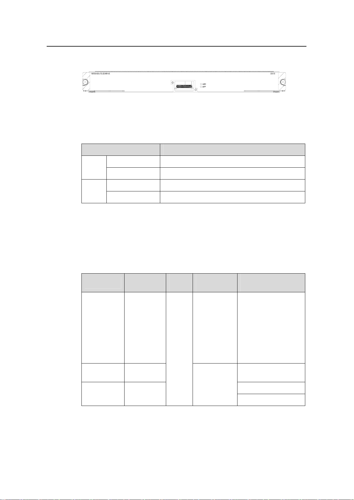
Figure 2-3 XK1 module panel
The XK1 module has two port LEDs for the 10GE port on its panel.
Table 2-7 Port LEDs on the XK1 module
LED Status
LINK
OFF No link is present.
Green ON A link is present.
OFF No packets are transmitted/received on the port.
ACT
Orange blinking Packets are being transmitted/received on the port.
2.4.3 Matching Cable
The XK1 module provides one 10GE XENPAK/SC optical or electrical port. You can
use these XENPAK optical modules.
Table 2-8 Interface modules available for the XK1 module
SFP module
10GBASE-S
R-XENPAK
Central
wavelength
850 nm
Conne
ctor
SC
Matching
cable
Multimode
optical fiber
cable
Transmission
distance
26 m (85.3 ft) for the
62.5 µm MMF w/
160MHz*km cable;
82 m (269.0 ft) for the
50 µm MMF w/
500MHz*km cable;
300 m (984.3 ft) for the
50 µm MMF w/
2000MHz*km cable
10GBASE-L
R-XENPAK
10GBASE-E
R-XENPAK
1310 nm 10 km (6 mi)
Single mode
1550 nm
optical fiber
cable
40 km (25 mi)
80 km (50 mi)
2-5
Page 47
Installation Manual
H3C S9500 Series Routing Switches Chapter 2 LPU Modules
2.5 GP12 Module
2.5.1 Specifications
The GP12 module provides 12 × 1000 Mbps SFP/LC optical ports.
Table 2-9 GP12 module specifications
Attribute GP12
CPU MPC8245
Boot ROM` 512 KB
SDRAM 128 MB/256 MB
Dimensions (L × W) 366.7 × 340 mm (14.4 × 13.4 in.)
Max. power consumption 55 W
Number of ports 12
Connector SFP/LC
Rate 1000 Mbps
2.5.2 Panel and LEDs
Figure 2-4 GP12 module panel
The GP12 module has two LEDs for each port on its panel.
Table 2-10 Port LEDs on the GP12 module
LED Status
OFF No link is present.
LINK
Green A link is present.
OFF No packets are transmitted/received on the port.
ACT
Orange blinking Packets are being transmitted/received on the p ort.
2.5.3 Matching Cable
The GP12 module can provide 12 × 1000 Mbps optical ports. You can use these SFP
optical modules:
2-6
Page 48

Installation Manual
H3C S9500 Series Routing Switches Chapter 2 LPU Modules
Table 2-11 Interface modules available for the GP12 module
SFP module
1000BASE-SX-SFP 850 nm
1000BASE-LX-SFP 10 km (6 mi)
1000BASE-LH-SFP
1000BASE-ZX-LR-
SFP
1000BASE-ZX-VR-
SFP
1000BASE-ZX-UR-
SFP
Central
wavelength
1310 nm
1550 nm
Connector
LC
Matching
cable
50/125 µm
multimode
optical fiber
cable
62.5/125 µm
multimode
optical fiber
cable
9/125 µm
single mode
optical fiber
cable
Transmission
distance
550 m (1804
ft)
275 m (902 ft)
40 km (25 mi)
70 km (43 mi)
100km (62 mi)
2.6 GP24 Module
2.6.1 Specifications
The GP24 module provides 24 × 1000 Mbps SFP/LC optical ports.
Table 2-12 GP24 module specifications
CPU MPC8245
Boot ROM 512 KB
SDRAM 128 MB/256MB
Dimensions (L × W) 366.7 × 340 mm (14.4 × 13.4 in.)
Max. power consumption 100 W
Number of ports 24
Connector SFP/LC
Rate 1000 Mbps
Attribute GP24
2-7
Page 49
Installation Manual
H3C S9500 Series Routing Switches Chapter 2 LPU Modules
2.6.2 Panel and LEDs
Figure 2-5 GP24 module panel
The GP24 module has two LEDs for each 1000 Mbps optical port on its panel.
Table 2-13 Port LEDs on the GP24 module
LED Status
LINK
ACT
2.6.3 Matching Cable
The GP24 module provides 24 × 1000 Mbps optical ports. For more details about SFP
optical modules, see
2.7 FP20 Module
2.7.1 Specifications
The FP20 module provides 20 × 100 Mbps SFP/LC optical ports.
Table 2-14 FP20 module specifications
OFF No link is present.
Green A link is present.
OFF No packets are transmitted/received on the port.
Orange blinking Packets are being transmitted/received on the port.
Table 2-11
Attribute FP20
CPU MPC8245
Boot ROM 512 KB
SDRAM 128 MB/256 MB
Dimensions (L × W) 366.7 × 340 mm (14.4 × 13.4 in.)
Max. power consumption 50W
Port 20
Connector SFP/LC
Rate 100 Mbps full duplex
2-8
Page 50

Installation Manual
H3C S9500 Series Routing Switches Chapter 2 LPU Modules
2.7.2 Panel and LEDs
Figure 2-6 FP20 module panel
The FP20 module has two LEDs for each port on its panel.
Table 2-15 Port LEDs on FP20 module
LED Status
LINK
OFF No link is present.
Green A link is present.
OFF No packets are tran smitted/received on the port.
ACT
Orange blinking Packets are being transmitted/received on the port.
2.7.3 Matching Cable
The FP20 module provides 20 × 100 Mbps SFP optical ports. You can use these SFP
optical modules:
Table 2-16 Interface modules available for the FP20 module
SFP module
100BASE-FXMM-SFP
Central
wavelength
1310 nm
Connector Matching cable
50/125 µm
multimode
optical fiber
cable
62.5/125 µm
multimode
optical fiber
LC
cable
Transmission
distance
2 km (1 mi)
100BASE-FXSM-SFP
100BASE-FXSM-LR-SFP
100BASE-FXSM-VR-SFP
1550 nm
2-9
9/125 µm single
mode optical
fiber
15 km (9 mi)
40 km (25 mi)
80 km (50 mi)
Page 51

Installation Manual
H3C S9500 Series Routing Switches Chapter 2 LPU Modules
2.8 F32G Module
2.8.1 Specifications
The F32G module provides four 1000 Mbps SFP/LC optical ports and 32 x 10/100
Mbps auto-sensing RJ-45 ports.
Table 2-17 F32G module specifications
Attribute F32G
CPU MPC8245
Boot ROM 512 KB
SDRAM 128 MB/256 MB
Dimensions (L × W) 366.7 × 340 mm (14.4 × 13.4 in.)
Max. power consumption 55 W
Number of ports
Connector RJ-45, SFP/LC
Rate
2.8.2 Panel and LEDs
Figure 2-7 F32G module panel
The F32G module has two LEDs for each 1000 Mbps port on its panel.
Table 2-18 1000 Mbps port LEDs on the F32G module
Four 1000 Mbps SFP/LC optical ports
32 x 10/100 Mbps auto-sensing RJ-45 ports
10 Mbps, half/full duplex
100 Mbps, half/full duplex
1000 Mbps, full duplex
LED Status
LINK
ACT
The F32G module has one LED for each 100 Mbps port on its panel.
OFF No link is present.
Green A link is present.
OFF No packets are transmitted/received on the port.
Orange blinking Packets are being transmitted/received on the port.
2-10
Page 52

Installation Manual
H3C S9500 Series Routing Switches Chapter 2 LPU Modules
Table 2-19 100 Mbps port LEDs on F32G module
LED Status
ON A link is present on the port.
LINK/ACT
2.8.3 Matching Cable
The F32G can provide four 1000 Mbps SFP optical ports. For more details about the
SFP modules, see
The 32 × 10/100 Mbps electrical ports on the F32G module use RJ-45 connectors and
category-5 twisted pair cables which allow the transmission distance of 100 m (328 ft).
PIN #8
PIN #1
Figure 2-8 RJ-45 connector
OFF No link is present on the port.
Blinking Packets are being transmitted/received on the port.
Table 2-11.
Table 2-20 Pin assignment of the RJ-45 MDI connector
10Base-T/100Base-TX
Pin No.
Signal Function
1 Tx+ Transmit data.
2 Tx- Transmit data.
3 Rx+ Receive data.
4 Reserved 5 Reserved 6 Rx- Receive data.
7 Reserved 8 Reserved -
2-11
Page 53

Installation Manual
H3C S9500 Series Routing Switches Chapter 2 LPU Modules
Table 2-21 Pin assignment of the RJ-45 MDI-X connector
Pin No.
Signal Function
1 Rx+ Receive data.
2 Rx- Receive data.
3 Tx+ Transmit data.
4 Reserved 5 Reserved 6 Tx- Transmit data.
7 Reserved 8 Reserved -
Note:
Tx = Transmit data; Rx = Receive data
10Base-T/100Base-TX
2.9 GT24 Module
2.9.1 Specifications
The GT24 module provides 24 × 10/100/1000 Mbps auto-sensing RJ-45 ports.
Table 2-22 GT24 module specifications
CPU MPC8245
Boot ROM 512 KB
SDRAM 128 MB/256 MB
Dimensions (L × W) 366.7 × 340 mm (14.4 × 13.4 in.)
Max. power consumption 110 W
Number of ports 24
Connector RJ-45
Rate 10/100/1000 Mbps
Attribute GT24
2-12
Page 54

Installation Manual
H3C S9500 Series Routing Switches Chapter 2 LPU Modules
2.9.2 Panel and LEDs
Figure 2-9 GT24 module panel
The GT24 module has one LEDs for each port on its panel.
Table 2-23 Port LEDs on the GT24 module
LED Status
ON No link is present.
LINK/ACT
2.9.3 Matching Cable
The ports on the GT24 module uses RJ-45 connectors (see Table 2-24) and category-5
twisted pair cables which allow the transmission distance of 10 0 m (328 ft).
PIN #8
PIN #1
Figure 2-10 RJ-45 connector
Table 2-24 Pin assignment of the RJ-45 GE connector
OFF A link is present.
Blinking Packets are being transmitted/received on the port.
Pin No.
10Base-T/100Base-T/1000Base-TX
Signal Function
1 MX_0+ Transmit and receive data.
2 MX_0- Transmit and receive data.
3 MX_1+ Transmit and receive data.
4 MX_2+ Transmit and receive data.
5 MX_2- Transmit and receive data.
6 MX_1- Transmit and receive data.
2-13
Page 55

Installation Manual
H3C S9500 Series Routing Switches Chapter 2 LPU Modules
Pin No.
7 MX_3+ Transmit and receive data.
8 MX_3- Transmit and receive data.
10Base-T/100Base-T/1000Base-TX
Signal Function
2.10 GV48 Module
2.10.1 Specifications
The GV48 module provides 48 x 10/100/1000 Mbps auto-sensing PoE-capable RJ-45
ports.
Table 2-25 GV48 module specifications
Attribute GV48
CPU MPC8245
BootROM 512 KB
SDRAM 256 MB
Dimensions (L× W) 366.7 × 340 mm (14.4 × 13.4 in.)
Number of ports 48
Connector RJ-45
Rate 10/100/1000 Mbps
2.10.2 Panel and LEDs
Figure 2-11 GV48 module panel
The GV48 module has one LED for each port on its panel.
Table 2-26 1000 Mbps electrical port LEDs on the GV48 module
LED Status
ON A link is present.
LINK/ACT
OFF No link is present.
Blinking Packets are being transmitted/received on the port.
2-14
Page 56

Installation Manual
H3C S9500 Series Routing Switches Chapter 2 LPU Modules
2.10.3 Matching Cable
For more details, see section 2.9.3 Matching Cable
2.11 FT48 Module
2.11.1 Specifications
The FT48 module provides 48 x 10/100 Mbps auto-sensing RJ-45 ports.
Table 2-27 FT48 module specifications
Attribute FT48
CPU MPC8245
Boot ROM 512 KB
SDRAM 128 MB/256 MB
Dimensions (L × W) 366.7 × 340 mm (14.4 × 13.4 in.)
Max. power consumption 55 W
Port 48
Connector RJ-45
Rate
2.11.2 Panel and LEDs
Figure 2-12 FT48 module panel
The FT48 module has one LED for each port on its panel.
Table 2-28 Port LEDs on FT48 module
LED Status
10 Mbps, half/full duplex
100 Mbps, half/full duplex
FT48A
LINK/ACT
ON A link is present.
OFF No link is present.
Blinking Packets are being transmitted/received on the port.
2-15
Page 57

Installation Manual
H3C S9500 Series Routing Switches Chapter 2 LPU Modules
2.11.3 Matching Cable
The FT48 module uses RJ-45 connectors and category-5 twisted pair cables which
allow the transmission distance of 100 m.
PIN #8
PIN #1
Figure 2-13 RJ-45 connector
Table 2-29 Pin assignment of the RJ-45 MDI connector
Pin No.
10Base-T/100Base-TX
Signal Functionality
1 Tx+ Transmit data.
2 Tx- Transmit data.
3 Rx+ Receive data.
4 Reserved 5 Reserved 6 Rx- Receive data.
7 Reserved 8 Reserved -
Table 2-30 Pin assignment of RJ-45 MDI-X connector
10Base-T/100Base-TX
Pin No.
Signal Functionality
1 Rx+ Receive data.
2 Rx- Receive data.
3 Tx+ Transmit data.
4 Reserved 5 Reserved 6 Tx- Transmit data.
7 Reserved 8 Reserved -
2-16
Page 58

Installation Manual
H3C S9500 Series Routing Switches Chapter 2 LPU Modules
Note:
Tx = Transmit data; Rx = Receive data
2.12 P4G8 Module
2.12.1 Specifications
The P4G8 module provides eight 1000 Mbps SFP/LC optical ports and four
OC-3c-POS optical ports.
Table 2-31 P4G8 module specifications
Attribute P4G8
CPU MPC8245
Boot ROM 512 KB
SDRAM 128 MB/256 MB
Dimensions (L × W) 366.7 × 340 mm (14.4 × 13.4 in)
Max. power consumption 55 W
Number of ports
Connector SFP/LC
Rate
2.12.2 Panel and LEDs
Figure 2-14 P4G8 module panel
The P4G8 module has two LEDs for each port on its panel.
Eight 1000 Mbps SFP/LC optical ports Four
OC-3c-POS optical ports.
1000 Mbps
155 Mbps
Table 2-32 1000 Mbps port LEDs on the P4G8 module
LED Status
LINK
OFF No link is present.
Green A link is present.
2-17
Page 59

Installation Manual
H3C S9500 Series Routing Switches Chapter 2 LPU Modules
LED Status
ACT
OFF No packets are transmitted/received on the port.
Orange blinking Packets are being transmitted/received on the port.
Table 2-33 POS port LEDs on the P4G8 module
LED Status
ALM
ACT
2.12.3 Matching Cable
The GP24 module provides eight 1000 Mbps SFP optical port s. Fo r more det ails about
SFP optical modules, see
The GP24 module also provides four OC-3c-POS optical ports. For more details about
100 Mbps SFP optical modules (to provide OC-3c-POS optical ports), see
OFF The link is normal.
ON No link is present or the link is faulty.
OFF No packets are transmitted/received on the port.
ON Packets are being transmitted/received on the port.
Table 2-11.
Table 2-16.
2.13 SP4 Module
2.13.1 Specifications
The SP4 module provides four OC-48c-POS optical ports.
Table 2-34 SP4 module specifications
CPU MPC8245
BootROM 512 KB
SDRAM 256 MB
Dimensions (L × W) 366.7 × 340 mm (14.4 × 13.4 in)
Max. power consumption 97 W
Number of ports Four
Connector SFP/LC
Rate 2.5 Gbps
Attribute SP4
2-18
Page 60
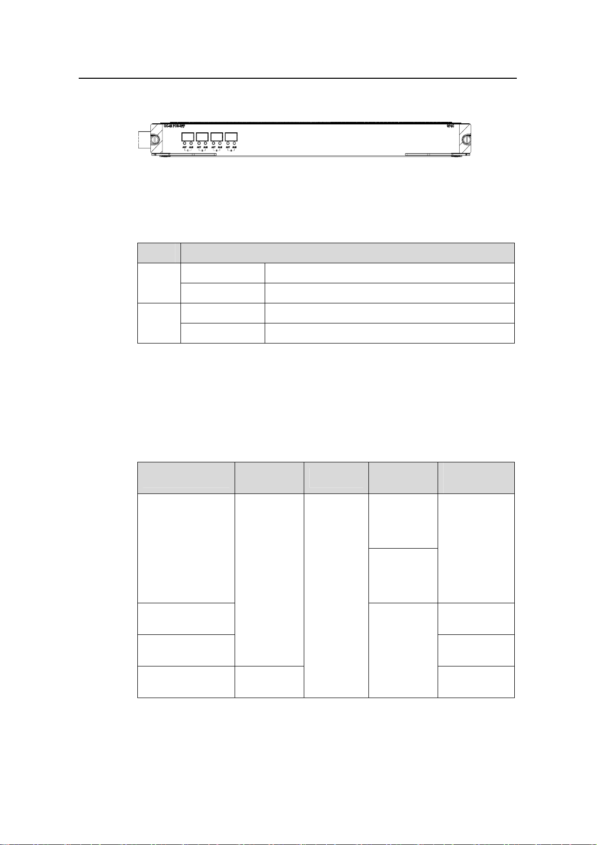
Installation Manual
H3C S9500 Series Routing Switches Chapter 2 LPU Modules
2.13.2 Panel and LEDs
Figure 2-15 SP4 module panel
The SP4 module has two LEDs for each port on its panel.
Table 2-35 POS port LEDs for the SP4 module
LED Status
ALM
OFF No link is present.
Green A link is present.
OFF No packets are transmitted/received on the port.
ACT
Orange blinking Packets are being transmitted/received on the port.
2.13.3 Matching Cable
The SP4 module provides four OC-48c-POS optical ports. To provide optical ports, you
can use these SFP optical modules.
Table 2-36 Optical port modules available for the SP4 module
SFP module
2.5GBASE-FX-MM
-SFP
Central
wavelength
1310 nm
Connector
LC
Matching
cable
50/125 µm
multimode
optical fiber
cable
62.5/125 µm
multimode
optical fiber
cable
Transmission
distance
2 km (1 mi)
2.5GBASE-FX-SMSFP
2.5GBASE-FX-SMLR-SFP
2.5GBASE-FX-SMVR-SFP
1550 nm
2-19
15 km (9 mi)
9/125 µm
single mode
optical fiber
40 km (25 mi)
cable
80 km (50 mi)
Page 61

Installation Manual
H3C S9500 Series Routing Switches Chapter 2 LPU Modules
2.14 UP1 Module
2.14.1 Specifications
The UP1 module provides one OC-192c XFP/LC POS optical ports.
Table 2-37 UP1 module specifications
Attribute UP1
CPU MPC8245
Boot ROM 512 KB
SDRAM 256 MB
Dimensions (L × W) 366.7 × 340 mm (14.4 × 13.4 in)
Max. power consumption 92 W
Number of ports One
Connector XFP/LC
Rate 10 Gbps
2.14.2 Panel and LEDs
Figure 2-16 UP1 module panel
The UP1 module has two LEDs for each port on its panel.
Table 2-38 POS port LEDs
LED Status
OFF The link is normal.
ALM
ON No link is present or the link is faulty.
OFF No packets are transmitted/received on the port.
ACT
ON Packets are being transmitted/received on the port.
2.14.3 Matching Cable
The UP1 module provides one OC-192c XFP/LC POS optical port. For more details
about XFP optical modules (to provide 10 Gbps POS optical ports), see
Table 2-3.
2-20
Page 62

Installation Manual
H3C S9500 Series Routing Switches Table of Contents
Table of Contents
Chapter 3 Installation Preparation............................................................................................... 3-1
3.1 Safety Recommendations.................................................................................................. 3-1
3.1.1 General Safety Recommendations ......................................................................... 3-1
3.1.2 Safety Recommendations against Electricity.......................................................... 3-1
3.1.3 Safety Recommendations in Moving the S9500 Series.......................................... 3-1
3.1.4 Wearing an ESD-Preventive Wrist Strap ................................................................ 3-2
3.1.5 Safety Recommendations against Laser ................................................................ 3-2
3.2 Examining Installation Site................................................................................................. 3-3
3.2.1 Temperature/Humidity Requirements ..................................................................... 3-3
3.2.2 Cleanness Requirements........................................................................................ 3-3
3.2.3 Anti-Static Requirements ........................................................................................ 3-4
3.2.4 Grounding Requirements........................................................................................ 3-5
3.2.5 Power Supply Requirements................................................................................... 3-5
3.2.6 Space Requirements............................................................................................... 3-5
3.2.7 Cabinet-Mounting Requirements ............................................................................ 3-5
3.3 Installation Tools................................................................................................................ 3-6
i
Page 63

Installation Manual
H3C S9500 Series Routing Switches Chapter 3 Installation Preparation
Chapter 3 Installation Preparation
3.1 Safety Recommendations
To avoid possible bodily injury and device impairment, please read the following safety
recommendations carefully before installing the S9500 series. The recommendations
do not cover every possible hazardous condition.
3.1.1 General Safety Recommendations
z The S9500 series use redundant PSUs. Turn off all PSUs and remove all the
power cords before opening the chassis.
z Keep the chassis clean and dust-free.
z Keep the chassis and installation tools away from walk areas.
3.1.2 Safety Recommendations against Electricity
z Look carefully for possible hazards in your work area, such as ungrounded power
extension cables, missing safety grounds, and moist floors.
z Locate the emergency power-off switch in the room before installation. Shut the
power off at once in case accident occurs.
z Unplug all the power cords and external cables before moving the chassis.
z Better not maintain the equipment alone when it has been powered.
z Never assume but check each time that power has been disconnected from a
circuit.
z Do not place the switch on a moist area and avoid liquid flowing into the switch.
3.1.3 Safety Recommendations in Moving the S9500 Series
The S9500 series are rather big and heavy, so follow the recommendations below
when moving it.
z Remove all the external cables (including power cords) before moving the chassis.
z Do not move the switch alone. Work with another person.
z Move the switch slowly and stably. Never move suddenly or twist your body.
z Move the switch at stable and consistent paces with your peer. Keep balance of
your body.
3-1
Page 64

Installation Manual
H3C S9500 Series Routing Switches Chapter 3 Installation Preparation
Caution:
You can only hold the handles at both sides of the chassis when moving the switch, but
not the plastic panel of the chassis, the handle of the fan frame, the handle of the PSUs
or the air vents of chassis.
As these parts are not designed for bearing the weight of the entire chassis, any
attempt trying to carry the switch with these parts may impair the switch and even injure
yourself.
3.1.4 Wearing an ESD-Preventive Wrist Strap
To prevent the electronic components from being damaged by the electrostatic
discharge (ESD), take ESD measures for the area where the switch is located and note
the issues below:
z Always wear an ESD-preventive wrist strap when installing the parts, especially
the electric printed circuit boards.
z Hold the circuit board by the edge. Do not touch the components or the electric
printed circuit.
Take the following steps to use the ESD-preventive wrist strap.
Step 1: Wear the wrist strap on your wrist.
Step 2: Lock the wrist strap tight around your wrist to keep good contact with the skin.
Step 3: Insert it into the hole peculiar to ESD-preventive wrist strap in the chassis or
attach it to the grounding screw of the chassis the alligator clips.
Step 4: Make sure that the ESD-preventive wrist strap is well grounded.
Caution:
For the sake of safety, check the resistance of the ESD-preventive wrist strap. The
resistance reading should be in the range of 1 to 10 Mohm between human body and
the ground.
3.1.5 Safety Recommendations against Laser
Some LPUs of the S9500 series have optical interfaces. In operating status, it is
prohibited to stare into the open optical interface because the laser being transmitted
through the optical fiber will produces a small beam of light which has very high power
3-2
Page 65

Installation Manual
H3C S9500 Series Routing Switches Chapter 3 Installation Preparation
density and is invisible to human eyes; when a beam of light enters the eye, retina may
be burned.
Caution:
The laser inside the optical fiber may hurt your eyes.
3.2 Examining Installation Site
The S9500 series can only be used indoors. To ensure that the switch works normally
and to prolong its service lifetime, the following requirements should be met in terms of
installation environment.
3.2.1 Temperature/Humidity Requirements
To ensure the normal operation and service lifetime of a switch, proper temperature
and humidity should be maintained in the equipment room. Long-lasting high humidity
in the equipment room is prone to poor insulation or even leakage of the insulating
material. Sometimes, the mechanical performance deterioration, the rustiness and
corrosion of some metal parts are also more likely to occur. If the relative humidity is too
low, the captive screws may become loose due to the insulation washer contraction.
Meanwhile, the electrostatic is likely to be produced in the dry environment, which will
jeopardize the CMOS circuit of the switch. The higher the temperature, the greater the
damage it will do to the switch. Long-lasting high temperature will speed up the aging
process of the insulating materials, greatly lower the reliability of the switch, and
therefore affect its service life seriously.
3.2.2 Cleanness Requirements
Dust is a hazard to the operating safety of the switch. The indoor dust accumulated on
the chassis can cause electrostatic adsorption, which may result in the poor contact of
the connector or metal contact point. This happens more frequently when indoor
relative humidity is low, which will not only shorten the service life of the switch, but also
cause communication failure.
The required specifications on dust content and particle diameter in an equipment room
are shown in the following table.
3-3
Page 66

Installation Manual
H3C S9500 Series Routing Switches Chapter 3 Installation Preparation
Table 3-1 Limitation on dust content in equipment room
Mechanical active
material
Dust particle particles/m³
Unit Content
≤3 x 10
4
(No visible dust on desk in three days)
Note: Dust particle diameter ≥ 5µm
Besides the dust specifications, the equipment room of the switch should also meet the
rigorous requirements for the content of salt, acid and sulfide in the air. These harmful
gases could accelerate the metal erosion and the aging process of some parts.
Incursion of harmful gases, such as SO
, H2S, NO2, NH3, and Cl2, should be prevented.
2
The specific limitation values of these harmful gases are given in the following table.
Table 3-2 Harmful gas limits in an equipment room
Gas Average (mg/m3) Max. (mg/m3)
SO
2
0.3 1.0
H2S 0.1 0.5
NO
2
0.004 0.15
NH
3
Cl
2
3.2.3 Anti-Static Requirements
Any possible interference sources, no matter outside or inside the system, affect the
switch in use in a way of capacitive coupling, inductive coupling, electromagnetic
radiation, common impedance (including the grounding system) coupling or conducting
line (power line, signaling line and transmission line etc). To prevent the interference,
you should:
z Take effective measures against electrical net interference for power supply
system.
z Separate the working ground of the switch from the grounding device of the power
supply equipment or lightning-protection grounding device as far as possible.
z Keep the switch far away from the radio launcher, radar launcher, and
high-frequency devices working in the high current.
z Adopt electromagnetic shielding if necessary.
1.0 3
0.1 0.3
3-4
Page 67

Installation Manual
H3C S9500 Series Routing Switches Chapter 3 Installation Preparation
3.2.4 Grounding Requirements
A good grounding system is not only the basis essential to the stable and reliable switch
operation, but also an important guarantee of lightning protection, anti-interference and
ESD-prevention. The user must provide good grounding system for the switch.
3.2.5 Power Supply Requirements
The S9500 series adopt redundant PSUs. Where,
z AC PSU:
Rated voltage: 100 VAC to 240 VAC, 50 Hz or 60 Hz
Maximum tolerance: 90 VAC to 264 VAC, 50 Hz or 60 Hz
Maximum power output: 600 W (S8502)/1200 W (S9505)/2000 W (S9508/S9512)
z DC PSU:
Rated voltage: –60 VDC to –48 VDC
Maximum tolerance: –72 VDC to –36 VDC
Maximum power output: 600 W (S8502)/1200 W (S9505)/2000 W (S9508/S9512)
3.2.6 Space Requirements
For the sake of adequate ventilation and easy equipment maintenance, you are
recommended to keep one meter of clearance between the rear/front of the switch
cabinet and the wall surface or other devices. If the optional cabinet is desired, the clear
height of the equipment room must be more than 3 meters inclusive.
3.2.7 Cabinet-Mounting Requirements
Before cabinet-mounting the switch, make sure that the cabinet meets the following
requirements:
z Better mount the switch in an open cabinet. However, if you want to mount it in a
closed cabinet, make sure of the availability of a good ventilation system.
z Make sure that the cabinet stands steadily enough to support the weight of the
switch and the accessories.
z Make sure that the switch fits the cabinet size. Leave some clearance beside the
left and right panels of the switch for chassis ventilation.
3-5
Page 68

Installation Manual
H3C S9500 Series Routing Switches Chapter 3 Installation Preparation
3.3 Installation Tools
Table 3-3 Required installation tools
Measure
and
lineation
tools
Long tape, ruler (1 meter in length), gradienter, marking
pen, powder marker, pencil
General
tools
Drills
Fastening
tools
Small tools
Auxiliary
tools
Special tools
Meters
One percussion drill, several drill bits, one vacuum
cleaner
Flat-blade screwdriver P4 -- 75 mm
Phillips screwdriver P1 -- 100mm, P2 -- 150mm and P3
-- 250mm
Socket wrench M5
Box-end wrench M6
Double ring spanner (10-12) or open-end wrench
(10-12)
Sharp-nose pliers, diagonal pliers, vices, hand-held
electric drill, file, handsaw, crowbar, rubber hammer
Brush, tweezers, paper knife, hand bellows, electric
iron, solder wire, fork, ladder
ESD-preventive wrist strap, cable stripper, crimping
pliers, RJ-45 crimping pliers, wire punchdown tool
Multimeter, 500V Meg-ohmmeter (used for measuring
the insulation resistance), error detector, optical power
meter, earth resistance tester
Note:
The instruments and tools are not shipped with the S9500 series and it is up to the
users to ensure their availability.
3-6
Page 69

Installation Manual
H3C S9500 Series Routing Switches Table of Contents
Table of Contents
Chapter 4 Switch Installation....................................................................................................... 4-1
4.1 Confirming Installation Preparation....................................................................................4-1
4.2 Installation Flow.................................................................................................................4-1
4.3 Mounting the Switch in User-Supplied Cabinet.................................................................4-2
4.3.1 Cabinet Configuration Guideline............................................................................. 4-2
4.3.2 Mounting the Switch in Cabinet...............................................................................4-6
4.4 Mounting the Switch in B68 Cabinet.................................................................................. 4-7
4.4.1 Installing B68 Cabinet............................................................................................. 4-7
4.4.2 Remodeling B68 Cabinet........................................................................................4-7
4.5 Connecting PGND Wire and Power Cord..........................................................................4-7
4.5.1 Connecting PGND Wire.......................................................................................... 4-7
4.5.2 Connecting AC Power Cord.................................................................................. 4-10
4.5.3 Connecting DC Power Cord.................................................................................. 4-13
4.5.4 Connecting PoE Power Cord................................................................................4-15
4.6 Installing the AC Power Distribution Box......................................................................... 4-16
4.6.1 Terminal Block.......................................................................................................4-16
4.6.2 Power Distribution Box.......................................................................................... 4-17
4.7 Installing DC Power Distribution Box...............................................................................4-20
4.7.1 Terminal Block.......................................................................................................4-20
4.7.2 Installation of Power Distribution Box ...................................................................4-21
4.8 Installing Cabling Rack.................................................................................................... 4-23
4.9 Installing Fan Tray........................................................................................................... 4-23
4.10 Installing LPU................................................................................................................. 4-24
4.11 Connecting Interface Cables......................................................................................... 4-25
4.11.1 Connecting Console Cable................................................................................. 4-25
4.11.2 Connecting AUX Cable....................................................................................... 4-26
4.11.3 Connecting Category-5 Shielded Cable..............................................................4-27
4.11.4 Connecting Fiber.................................................................................................4-27
4.12 Cable Routing Recommendations.................................................................................4-28
4.12.1 Freestanding Switch on Tabletop........................................................................4-28
4.12.2 Cabinet-Mounting Switch....................................................................................4-29
4.13 Cable Management .......................................................................................................4-29
4.13.1 Correct Labels..................................................................................................... 4-29
4.13.2 Cable Management Requirements..................................................................... 4-29
4.14 Verifying the Installation................................................................................................. 4-32
i
Page 70

Installation Manual
H3C S9500 Series Routing Switches Chapter 4 Switch Installation
Chapter 4 Switch Installation
The S9500 series shall be installed indoors in a fixed place.
4.1 Confirming Installation Preparation
z Make sure that you have read Chapter 3 Installation Preparation carefully.
z All requirements mentioned in Chapter 3 Installation Preparation have been met.
4.2 Installation Flow
Start
Start
Confirm preparations
Confirm preparations
Check installati on site
Check installati on site
Install cabinet
Install cabinet
Install chassis and
Install chassis and
other c ompo nents
other c ompo nents
Conn ec t P GND wire/po wer c or d
Conn ec t P GND wire/po wer c or d
Install power distr ibution b ox in
Install power distr ibution b ox in
cabinet
cabinet
Install cabling r ack and fan tr ay
Install cabling r ack and fan tr ay
Insert LP U mo dules and
Insert LP U mo dules and
servic e pr oce s sor cards
servic e pr oce s sor cards
Conn ect cables to LP U mo dules
Conn ect cables to LP U mo dules
and service processor cards
and service processor cards
Figure 4-1 Installation flow
4-1
Page 71

Installation Manual
H3C S9500 Series Routing Switches Chapter 4 Switch Installation
4.3 Mounting the Switch in User-Supplied Cabinet
4.3.1 Cabinet Configuration Guideline
Caution:
z Even if no PoE external power supply is installed, you are recommended to reserve
the PoE power supply slot (just cover a 4 U blank filler panel) in the cabinet for later
PoE expansion.
z For components of 4 U or higher, such as chassis and PoE power supply, more
screws are required to secure the slide rails in the cabinet considering their weight.
z You can adjust the specific height of every slot as needed. The following guideline is
just for reference.
I. One S9505 chassis in a cabinet
The components and their height are as follows (from top down):
z Blank filler panel (2U)
z Cabling frame (2U)
z External PoE power supply (4U. It is blank filler panel if no external PoE power
supply is installed)
z Blank filler panel (1U)
z Backwards cabling frame (1U)
z S9505 chassis (11U)
z Blank filler panel (1U)
z Cabling frame (2U)
4-2
Page 72

Installation Manual
H3C S9500 Series Routing Switches Chapter 4 Switch Installation
S9505 11US9505 11U
(1) Blank filler panel (2) Cabling frame
(3) Backward cabling frame (4) External PoE power supply slot (or reserved)
Figure 4-2 One S9505 chassis in a cabinet
Guideline: The space marked in
Figure 4-2 must be reserved, and the remaining is at
your disposal.
II. Two S9505 chassis in a cabinet
The components and their height are as follows (from top down):
z Blank filler panel (2U)
z Cabling frame (2U)
z External PoE power supply (4U. It is blank filler panel if no external PoE power
supply is installed)
z Blank filler panel (1U)
z Backwards cabling frame (1U)
z S9505 chassis (11U)
z Blank filler panel (1U)
z Cabling frame (2U)
z S9505 chassis (11U)
4-3
Page 73

Installation Manual
H3C S9500 Series Routing Switches Chapter 4 Switch Installation
S9505 11U
S9505 11U
S9505 11U
S9505 11U
(1) Blank filler panel (2) Cabling frame
(3) Backward cabling frame (4) External PoE power supply slot (or reserved)
Figure 4-3 Two S9505 chassis in a cabinet
Guideline: The space marked in
Figure 4-3 must be reserved, and the remaining area is
at your disposal.
III. One S9508 chassis in a cabinet
The components and their height are as follows (from top down):
z Blank filler panel (2U)
z Cabling frame (2U)
z External PoE power supply (4U. It is blank filler panel if no external PoE power
supply is installed)
z Blank filler panel (1U)
z Backwards cabling frame (1U)
z S9508 chassis (14U)
z Blank filler panel (1U)
z Cabling frame (2U)
4-4
Page 74

Installation Manual
H3C S9500 Series Routing Switches Chapter 4 Switch Installation
S9508 14US9508 14U
(1) Blank filler panel (2) Cabling frame
(3) Backward cabling frame (4) External PoE power supply slot (or reserved)
Figure 4-4 One S9508 chassis in a cabinet
Guideline: The space marked in
Figure 4-4 must be reserved, and the remaining is at
your disposal.
IV. One S9512 chassis in a cabinet
The components and their height are as follows (from top down):
z Blank filler panel (2U)
z Cabling frame (2U)
z External PoE power supply (4U. It is blank filler panel if no external PoE power
supply is installed)
z Blank filler panel (1U)
z Backwards cabling frame (1U)
z S9512 chassis (17U)
z Blank filler panel (1U)
z Cabling frame (2U)
4-5
Page 75

Installation Manual
H3C S9500 Series Routing Switches Chapter 4 Switch Installation
S9512 17U
(1) Blank filler panel (2) Cabling frame
(3) Backward cabling frame (4) External Po E power supply slot (or reserved)
Figure 4-5 One S9512 chassis in a cabinet
Guideline: The space marked in
Figure 4-5must be reserved, and the remaining is at
your disposal.
4.3.2 Mounting the Switch in Cabinet
Step 1: Confirm before installation
z Make sure that the cabinet has been well fixed. The layout inside the cabinet for
switch installation has been well done and there is no obstruction inside or around
the cabinet.
z Make sure that the switch is ready for installation and has been carried to a place
convenient for further moving near the cabinet.
Step 2: Mount a shelf inside the cabinet depending on the position where you want to
put the switch.
Step 3: Install the cabling rack and attach the mounting ears shipped with the switch
onto the switch.
Step 4: Carry the switch at both sides with another person to the place in front of the
cabinet slowly.
Step 5: Lift the switch a little higher than the cabinet shelf, put it on the shelf, and push
it into the cabinet.
4-6
Page 76

Installation Manual
H3C S9500 Series Routing Switches Chapter 4 Switch Installation
Step 6: Align the mounting ears with the square holes in the posts of the cabinet, and
fasten the screws in the holes to fix the switch in the cabinet.
4.4 Mounting the Switch in B68 Cabinet
When purchasing the S9500 series, you may also select a B68 Series Cabinet as
needed. There are two types of B68 cabinets available for the S9500 series:
z B68-18 model: 1.8 m B68 cabinet (600 x 800 x 1800 mm, or 23.6 x 31.5 x 70.9 in.)
z B68-22 model: 2.2 m B68 cabinet (600 x 800 x 2200 mm or 23.6 x 31.5 x 86.7 in.)
Note:
Except for the height, B68-18 and B68-22 cabinets have the same requirements in
space planning, cabinet positioning, and fixing.
4.4.1 Installing B68 Cabinet
For the procedure of installing a B68 cabinet, refer to Appendix B.
4.4.2 Remodeling B68 Cabinet
For details, refer to the B68 Cabinet Remodel Introduction shipped with the device.
4.5 Connecting PGND Wire and Power Cord
4.5.1 Connecting PGND Wire
Caution:
For the safety of operators and equipment, the switch must be well grounded. The
resistance reading between switch chassis and the ground must be less than 1 ohm.
I. Common grounding environment
Step 1: Remove the screw from the grou nding hole in the switch chassis.
Step 2: Wear the connector of the PGND wire accompanied with the switch on the
grounding screw.
Step 3: Insert the grou nding screw into the grounding hole and screw it down.
4-7
Page 77

Installation Manual
H3C S9500 Series Routing Switches Chapter 4 Switch Installation
Step 4: Connect the other end of the ground wire to the ground bar of the switch.
Note:
Generally, the cabinets installed in equipment rooms are equipped with ground bar. In
this case, you can connect the PGND wire of the switch to the ground bar for it.
II. Other grounding environment
Following are some methods for grounding the switch in different grounding
environments that you are likely to encounter when installing the switch at different
places.
Note:
Rather than specifying the switch model or showing the actual location of the switch
power input or grounding screw, the following figures are primarily intended for
illustrating the switch grounding, either via grounding screw or power input, in specific
grounding environments.
z If a ground bar is available, attach one end of the yellow-green PGND wire of the
switch to a grounding bolt of the ground bar and faste n the captive nuts. Note th at
the fire main and lightning rod of a building are not suitable for grounding the
switch. The PGND wire of the switch should be connected to the grounding device
in the equipment room. (For the S9500 series, the grounding screw is on the rear
panel. Connect it as illustrated in
(5)
(5)
(5)
(5)
(5)
(5)
(1)
(1)
(1)
(1)
(1)
(1)
(2)
(2)
(2)
(2)
(2)
(2)
(3)
(3)
(3)
(3)
(3)
(3)
(4)
(4)
(4)
(4)
(4)
(4)
(1) Air filter (2) Grounding screw
(3) PGND wire (4) Ground b ar of the equipment room
(5) Rear panel of the switch
Figure 4-6).
Figure 4-6 Ground the switch when ground bar is available
4-8
Page 78
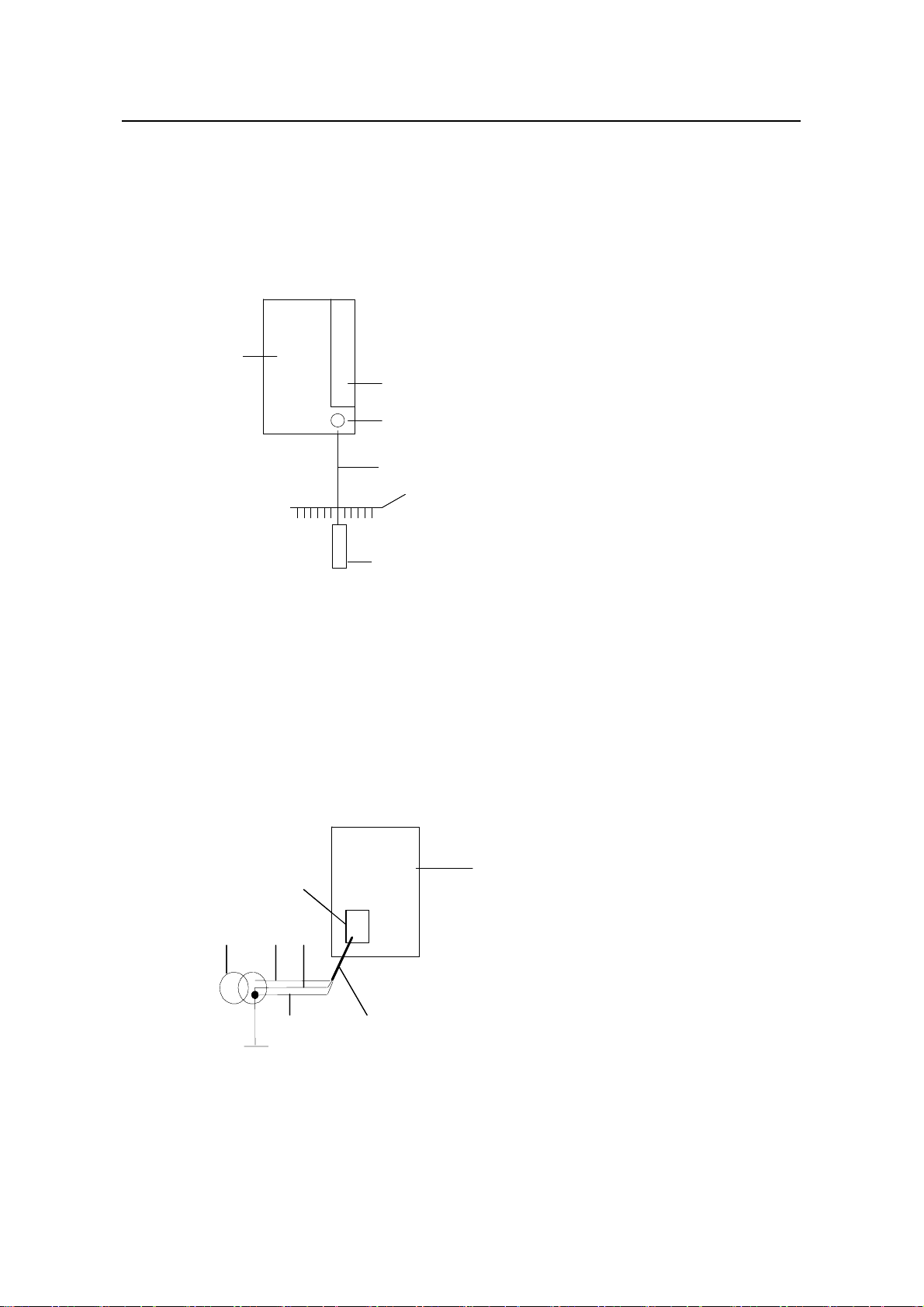
Installation Manual
H3C S9500 Series Routing Switches Chapter 4 Switch Installation
z If there is no ground bar but earth nearby and the grounding body is allowed to be
buried, you can simply hammer an angle iron or steel pipe no shorter than 0.5 m
into the earth. In this case, the yellow-green PGND wire should be welded with the
angle iron (steel pipe) and the joint should be processed against eroding. (F or the
S9500 series, the grounding screw is on the rear panel. Connect it as illustrated in
Figure 4-7).
(6)
(6)
(6)
(1)
(1)
(1)
(2)
(2)
(2)
(3)
(3)
(3)
(4)
(4)
(4)
(5)
(5)
(5)
(1) Air filter (2) Grounding screw
(3) PGND wire (4) Ground b ar of the equipment room
(5) Angle steel (6) Rear panel of the switch
Figure 4-7 Ground the switch when allowed to bury grounding body nearby
z If both ground bar and the conditions for burying the grounding body are not
available, an AC-powered Ethernet switch can be grounded using the PE wire of
the AC power supply. In this case, make sure that the PE wire of the AC power
supply has been well grounded at the power distribution room or AC power supply
transformer side.
(7)
(7)
(6)
(6)
(1) (2)(5)
(1) (2)(5)
(3) (4)
(3) (4)
(1) Live line (2) Neutral line
(3) PE line (4) 3-core AC i
(5) Transforme (6) AC power i
(7) Front panel
Figure 4-8 Gro via AC PE wire
r
of the switch
und the switch
4-9
nput cable
nput
Page 79

Installation Manual
H3C S9500 Series Routing Switches Chapter 4 Switch Installation
Note:
PE: Protection Earth
z If both ground bar and the conditions for burying the grounding body are not
available, a -48V DC-powered Ethernet switch can be grounded using the RTN
wire of the DC power supply. In this case, make sure that the RTN wire has been
well grounded at the DC egress of the DC power cabinet.
(11)
(11)
(12)
(12)
(1)
(1)
(9)
(9)
(10)
(2)
(2)
(4)
(4)
(6)
(6)
(3)
(3)
(5)
(5)
(8)
(8)
(13)
(13)
(10)
(7)
(7)
(1) AC/DC power cabinet (2) -48V line bank
(3) -48V output (4) RTN line bank
(5) RTN output (6) PGND line bank
(7) Earth ground (8) DC power input
(9) Grounding screw (10) Rear p el of the switch
(11) Front panel of the swit (12) Air filter
ch
(13) PGND wire
F cabinet via PGND o
igure 4-9 Ground the f the power cabinet
4.5.2 Conn
ecting AC Power Cord
Caution:
z For lightning protection, the AC power should be led through an external lightning
device into the switch.
z Make sure the power switch on the PSU is at OFF position before connecting the
power cord.
an
On the front panel of AC PSU, there is a connector-retention clamp.
4-10
Page 80

Installation Manual
H3C S9500 Series Routing Switches Chapter 4 Switch Installation
ect AC power cord for the S9502:
Conn
Step 1: Pull up the clamp at the left of the PSU front panel.
e
St p 2: Insert one end of the AC power cord accompanied with the switch into the
soc
ket on the PSU unit.
e
St p 3: Pull down the clamp to hold the power connecter.
Ste e other end of the power cord into the external power socket for the
p 4: Insert th
ch.
swit
(1) connector-retention clamp (2) Input LED
(3) Outp
ut LED (4) Fail LED
Figure 4-10 Connect AC power cord for the S9502
Connect AC power cord for the S9505/S9508/S9512:
Step 1: Pull the clamp at the left of the PSU front panel to the righ
Step 2: Insert one end of the AC power cord accompanied wit
socket on the PSU unit.
Step 3: Pull the clamp to the left to hold the power connector.
tep 4: Insert the other end o ord into the p
S
f the power c ower jack for the switch.
t.
h the switch into the
4-11
Page 81

Installation Manual
H3C S9500 Series Routing Switches Chapter 4 Switch Installation
(5)(5)
(1) Connector-r LED
(3) Output LED ail LED
(5) Power swit
etention clamp (2) Input
(4) F
ch
Figure 4-11 C er cord for the S9505
onnect AC pow
(1)
(1)
(2)
(2)
(3)
(3)
(4)
(4)
(5)
(5)
(1) Connector-retention clamp (2) Input LED
(3) Output LED (4) Fail LED
(5) Power switch
Figure 4-12 Con 9512 nect AC power cord for the S9508/S
4-12
Page 82

Installation Manual
H3C S9500 Series Routing Switches Chapter 4 Switch Installation
4.5.3 Connecting DC Power Cord
Caution:
Power OFF all the related parts of the switch before connecting the DC power cord.
In the connection of DC power cord, a connector bar will be used, and the power cord
will be tightened into the bar using screws for the sake of reliability.
onnect DC power cord for the S9502:
C
Step 1: Loosen the mounting nuts of the connectors on the DC PSU using the M6
socket wrench.
Step 2: Insert the -48V OT terminal
(with a blue wire) of the DC power cord
accompanied with the switch into the “-48V” connector on the PSU and fasten the
mounting nut. In
sert the peer end of the OT terminal into the “-48V” connector on the
external power supply.
Step 3: Insert one end of th e GND OT terminal (with a black wire) of the DC power cord
accompanied with the switch into the “RTN” connector on the PSU and fasten the
mounting nut. Insert the
peer end of the OT terminal into the “RTN” connector on the
external power supply.
Step 4: Insert one end of the PGND OT terminal (with a yellow-green wire) of the DC
power cord accompanied with the switch into the “PGND” connector on the PSU and
fasten the mounting nut.
Insert the peer end of the OT terminal to the ground bar for the
switch.
(1) -48V (2) RTN
(3) PGND (4) Input LED
(5) Output LED
(7) Connector block
(6) Fail LED
Figure 4-13 Connect DC power cord for the S9502
onnect the DC 9508/S9512
C power cord for the S9505/S switches.
4-13
Page 83

Installation Manual
H3C S9500 Series Routing Switches Chapter 4 Switch Installation
S ounting nuts of the co ectors on the DC PSU using the socket
tep 1: Loosen the m nn
wrench.
Step 2: Insert the -48V terminal (with a blue wire) of the DC power cord of the switch
into the “-48V” connector on the PSU and fasten the mounting nut. In
sert the other end
of the OT terminal into the “-48V” connector on the external power supply.
Step 3: In
sert one end of the GND OT terminal (with a black wire) of the DC powe r cord
into the “RTN” connector on the PSU, and fasten the mounting nut. Connect the other
end of the OT terminal to the RTN connector on the external power supply.
Step 4: Insert one end of the PGND OT terminal (with a yellow-green wire
) of the DC
power cord into the “PGND” connector on the PSU, and fasten the mounting nut.
Connect the other end of the OT terminal to the ground bar for the switch.
(1) Input LED (2) Output LED
(4) PGND (5) RTN
(3) Fail LED
(6) -48V
Figure 4-14 Connect DC power cord for the S9505
(7)
(7)
(6)
(6)
(1) Input LED (2) Output LED (3) Fa
(4) Power switch (5) PGND (6) RT
(7) -48V
Figure 4-15 Connect DC power cord for the S9508/S9512
(1)
(1)
(2)
(2)
(3)
(3)
(4)(5)
(4)(5)
il LED
N
4-14
Page 84

Installation Manual
H3C S9500 Series Routing Switches Chapter 4 Switch Installation
Note:
z -48V: -48 V
z RTN: -48 V working ground
z PGND: prote round
DC power supply
ction g
4.5.4 Connecting PoE Power Cord
Th can use PSE4500-A external PoE power supply,
e S9505/S9508/S9512 switch
ch is connected to the switch
whi through the PoE entry module.
The S9502 switch can use
connected to the switch through the PoE filter at the rear of the chassis, for the switch to
re
motely supply power to the connected PD devices.
Note:
This section only focuses on the cable connection between the external PoE power
supply and the S9500 series switch. For the installation of the external PoE power
supply, see the manual shipped with the power supply.
PSE2500-A1 external PoE power supply, which is
chassis I. Grounding PoE
You must g
round the PoE chassis before connecting the PoE power cord to it. Follow
these steps:
Connect the 6 AWG cable of the wiring terminal (with M6 hole) to the grou nding screw
on the rear panel of the switch, as shown in Figure 4-16.
C
onnect the other end of the cable to the grounding bar or other grounding terminals.
(1) Chassis grounding screw
4-15
(1)(1)
Page 85

Installation Manual
H3C S9500 Series Routing Switches Chapter 4 Switch Installation
Figure 4-16 Ground PoE chassis
II.
Connecting PoE power cable
Loosen the mounting screw of the PoE entry modul
Insert the -48V OT terminal (blue) of the DC power co
PoE entry module and fasten the mounting scre
e with a cross screwdriver .
rd to the NEG (-) terminal of the
w; insert the other end to the NEG (-)
terminal of the external PoE power supply.
Insert the GND OT terminal (black) of the DC powe
PoE entry module and fasten the mounting scre
r cord to the RTN (+) terminal of the
w; insert the other end to the NEG (-)
terminal of the external power supply.
Caution:
z Observe the signs on devices and connect the cables correctly.
z Choose right cables based on the load.
(1) DC output terminal: NEG(-) (2) DC output terminal: RTN(+)
3
( ) AC input switch (4) AC input socket
Figure 4-17 Front panel of external PoE pow
4.6 Inst lling the AC Power Distribution Box
a
er supply
4.6.1 Terminal Block
The terminal block is set on the bottom of a power distribution box.
4-16
Page 86

Installation Manual
H3C S9500 Series Routing Switches Chapter 4 Switch Installation
I. Appearance
Figure 4-18 Termi
nal block structure diagram
The terminal block has 21 terminals to connect power cords: seven gray termi
seven blue terminals and seven yellow-green terminals.
z The gray terminals from L1 to L7 are output ports for live wire. These po
rts are
connected to each other.
z The blue terminals from N1 to N7 are output ports for neutral wire. These port
connected to each other.
z The yellow-green terminals from PE1 to PE7 are output ports for earth wire. These
ports are connected to each other and connected to the cabinet.
II. Electrical performance of the terminal block
Inpu
t:
z Rated current: 76 A
z
Rated voltage: 1000 V
z Rated cross-sectional area: 16 mm
Maximum current/maximum crimping area: 101 A/25 mm
z
2
2
Output: seven loop outputs.
nals,
s are
4.6.2 Pow tribution Box
er Dis
I. p
Ap earance
Figure 4-19 Front view of the power distribution box
4-17
Page 87

Installation Manual
H3C S9500 Series Routing Switches Chapter 4 Switch Installation
Figure 4-20 Top view of the power distribution box
Caution:
z The power distribution box takes AC high voltage. Do not operate it before brea
its power.
z Make sure the power cord ports are covered with protection tube such that no wire
tailpiece is exposed at any joint.
II er cords to the power distribution box
. Connect pow
Use three
cabin
cross-se
sp cifications in different countries). Connect the power cords according to the
e
following relations
z istribution box — Live wire L in the cabinet power
cables to connect the client power distribution box to the terminal block of the
et power d
istribution box. You are recommended to use the cables with 16 mm
ctional area (the colors of the cables differ depending on the cable
:
Live wire L in the client power d
distribution box
z
Neutral wire N in the client power distribution box — Neutral wire N in the cabinet
power distribution box
z Earth wire G in the client power distribution box — Ea
rth wire PE in the cabinet
power distribution box
king
2
Use 3.5 m (11.5 ft) long cables to connect the cabinet power distribution box to the
system power supply and PoE power supply. The three wires of each cable should be
respectively connected to the ports L, N and PE of the power distribution box. Make
sure the protection
con ection. You should connect power cord 1 to L1, N1 and PE1, power cord 2 to L2,
n
and PE2, and s
N2 o on. The number of power cords depends on the cabinet
tubes are used and no wire tailpiece is exposed during the
configuration. Note that you should connect the brown wire to L (live wire), the blue wire
(neutral wire), and yello
to N w-green wire to PE (earth wire).
After finishing the connection of the cables, bind these cables in order with cable strap,
wire them along the right side of the cabinet down, and connect them to the input ports
4-18
Page 88

Installation Manual
H3C S9500 Series Routing Switches Chapter 4 Switch Installation
of the system power supply and PoE power supply. You should make sure the cables
are n
ot loose.
II
I. Installing the power distribution box
You should install the power distribution box on the top of the back of the B68 cabinet.
You can adjust the location of the box in a little range.
The following figure describes the cable connections on the cabinet power distribution
box.
Customer PDF
Customer PDF
Terminal
Guide rail
Guide rail
Power
Power
distribution box
distribution box
Terminal
block
block
B68 cabinet
B68 cabinet
Power cord 1
Power cord 1
S9500 chassis
S9500 chassis
PoE lightning
PoE lightning
protection box
protection box
S9500 chassis
S9500 chassis
System
System
power input
power input
PoE monitoring
PoE monitoring
board
board
PoE power
PoE power
supply
supply
Module 1 Module 2
Module 1 Module 2
Power cord 2
Power cord 2
Power cord 3
Power cord 3
Power cord 4
Power cord 4
Power cord 5
Power cord 5
Power cord 6
Power cord 6
Power cord 7
Power cord 7
Module 3
Module 3
PoE power
PoE power
input
input
Figure 4-21 Cable connections on the cabinet power distribution box
4-19
Page 89

Installation Manual
H3C S9500 Series Routing Switches Chapter 4 Switch Installation
4.7 Inst
alling DC Power Distribution Box
4.7.1 Terminal Block
I.
Terminal block structure diagram
Air Switch 1
Rail
terminal
Input
block
48V148
48V148
48V148
48V148
48V148
48V148
48V148
48V148
48V148
48V148
48V148
48V148
48V148
48V148
48V148
48V148
48V148
48V148
48V148
48V148
V2
V2
V2
V2
V2
V2
V2
V2
V2
V2
V2
V2
V2
V2
V2
V2
V2
V2
V2
V2
Clapboard
A ir Switch 2
B
B
B
B
B
B
B
B
B
B
B
B
B
B
B
B
B
B
B
B
B
B
B
B
B
B
B
B
B
B
B
B
B
B
B
B
B
G
G
G
G
G
G
G
G
G
G
G
G
G
G
G
G
G
G
G
G
G
G
G
G
G
G
G
G
G
G
G
G
G
G
G
G
G
N
N
N
N
N
N
N
N
N
N
N
N
N
N
N
N
N
N
N
N
N
N
N
N
N
N
N
N
N
N
N
N
N
N
N
N
N
D
D
D
D
D
D
D
D
D
D
D
D
D
D
D
D
D
D
D
D
D
D
D
D
D
D
D
D
D
D
D
D
D
D
D
D
D
BGND
terminal
block
B
B
B
B
B
B
B
B
B
B
B
B
B
B
B
B
B
B
B
B
B
B
B
B
B
B
B
B
B
B
B
B
B
B
B
G
G
G
G
G
G
G
G
G
G
G
G
G
G
G
G
G
G
G
G
G
G
G
G
G
G
G
G
G
G
G
G
G
G
N
N
N
N
N
N
N
N
N
N
N
N
N
N
N
N
N
N
N
N
N
N
N
N
N
N
N
N
N
N
N
N
N
N
D
D
D
D
D
D
D
D
D
D
D
D
D
D
D
D
D
D
D
D
D
D
D
D
D
D
D
D
D
D
D
D
D
D
B
B
B
B
B
B
B
B
B
B
B
B
B
B
B
B
B
B
B
B
B
B
B
B
B
B
B
B
B
B
B
B
B
G
G
G
G
G
G
G
G
G
G
G
G
G
G
G
G
G
G
G
G
G
G
G
G
G
G
G
G
G
G
G
G
G
G
N
N
N
N
N
N
N
N
N
N
N
N
N
N
N
N
N
N
N
N
N
N
N
N
N
N
N
N
N
N
N
N
N
N
D
D
D
D
D
D
D
D
D
D
D
D
D
D
D
D
D
D
D
D
D
D
D
D
D
D
D
D
D
D
D
D
D
D
P
P
P
P
P
P
P
P
P
P
P
P
P
P
P
P
P
P
P
P
P
P
P
P
P
P
P
P
P
P
P
P
P
P
P
P
P
P
P
P
P
P
P
P
P
P
P
P
P
P
P
P
P
P
G
G
G
G
G
G
G
G
G
G
G
G
G
G
G
G
G
G
G
G
G
G
G
G
G
G
G
G
G
G
G
G
G
G
G
G
G
G
G
G
G
G
G
G
G
G
G
G
G
G
G
G
G
G
N
N
N
N
N
N
N
N
N
N
N
N
N
N
N
N
N
N
N
N
N
N
N
N
N
N
N
N
N
N
N
N
N
N
N
N
N
N
N
N
N
N
N
N
N
N
N
N
N
N
N
N
N
N
D
D
D
D
D
D
D
D
D
D
D
D
D
D
D
D
D
D
D
D
D
D
D
D
D
D
D
D
D
D
D
D
D
D
D
D
D
D
D
D
D
D
D
D
D
D
D
D
D
D
D
D
D
D
Rail
PGND
terminal
block
Figure 4-22 Terminal block structure diagram
As illustrated in Figure 4-22, the two leftmost input terminal blocks are DC input
terminal blocks. Next to them are two air switches, each of which has a through-current
capacity of 63A. On the rightmost side are 9 terminal blocks, 6 of which are BGND
terminal blocks and the rest are PGND terminal blocks.
Diagram for connecting terminal blocks
II.
To DC
To DC Power
To DC
To DC Power
To DC
To DC Power
To DC
To DC Power
GND PGND
GND PGND
GND PGND
GND PGND
GND PGNDGND PGND
GND PGND
GND PGND
GND PGND
GND PGND
GND PGND
GND PGND
GND PGND
GND PGND
GND PGND
GND PGND
GND PGNDGND PGND
GND PGND
GND PGND
GND PGND
GND PGND
GND PGND
B
-48V1-48
-48V1-48
-48V1-48
-48V1-48
-48V1-48
-48V1-48
-48V1-48
-48V1-48
-48V1-48
-48V1-48
-48V1-48
-48V1-48
-48V1-48
-48V1-48
-48V1-48
-48V1-48
-48V1-48
-48V1-48
-48V1-48
-48V1-48
-48V1-48
-48V1-48
-48V1-48
V2
V2
V2
V2
V2
V2
V2
V2
V2
V2
V2
V2
V2
V2
V2
V2
V2
V2
V2
V2
V2
V2
V2
To -48V DC (-)
To -48V DC (-)
B
B
B
B
B
B
B
B
B
B
B
B
B
B
B
B
B
B
B
B
B
B
B
B
B
B
B
B
B
B
B
B
B
B
B
B
B
B
B
B
B
B
B
B
B
G
G
G
G
G
G
G
G
G
G
G
G
G
G
G
G
G
G
G
G
G
G
G
G
G
G
G
G
G
G
G
G
G
G
G
G
G
G
G
G
G
G
G
G
G
G
N
N
N
N
N
N
N
N
N
N
N
N
N
N
N
N
N
N
N
N
N
N
N
N
N
N
N
N
N
N
N
N
N
N
N
N
N
N
N
N
N
N
N
N
N
N
D
D
D
D
D
D
D
D
D
D
D
D
D
D
D
D
D
D
D
D
D
D
D
D
D
D
D
D
D
D
D
D
D
D
D
D
D
D
D
D
D
D
D
D
D
D
To -48V DC (+)
To -48V DC (+)
To -48V DC (+)
To -48V DC (+)
B
B
B
B
B
B
B
B
B
B
B
B
B
B
B
B
B
B
B
B
B
B
B
B
B
B
B
B
B
B
B
B
B
B
B
B
B
B
B
B
B
B
B
B
B
B
B
B
B
B
B
B
B
B
B
B
B
B
B
B
B
B
B
B
B
B
B
B
B
B
B
B
B
B
B
B
B
B
B
B
B
B
B
B
B
B
B
B
B
B
B
B
G
G
G
G
G
G
G
G
G
G
G
G
G
G
G
G
G
G
G
G
G
G
G
G
G
G
G
G
G
G
G
G
G
G
G
G
G
G
G
G
G
G
G
G
G
G
G
G
G
G
G
G
G
G
G
G
G
G
G
G
G
G
G
G
G
G
G
G
G
G
G
G
G
G
G
G
G
G
G
G
G
G
G
G
G
G
G
G
G
G
G
G
N
N
N
N
N
N
N
N
N
N
N
N
N
N
N
N
N
N
N
N
N
N
N
N
N
N
N
N
N
N
N
N
N
N
N
N
N
N
N
N
N
N
N
N
N
N
N
N
N
N
N
N
N
N
N
N
N
N
N
N
N
N
N
N
N
N
N
N
N
N
N
N
N
N
N
N
N
N
N
N
N
N
N
N
N
D
D
D
D
D
D
D
D
D
D
D
D
D
D
D
D
D
D
D
D
D
D
D
D
D
D
D
D
D
D
D
D
D
D
D
D
D
D
D
D
D
D
D
D
D
D
D
D
D
D
D
D
D
D
D
D
D
D
D
D
D
D
D
D
D
D
D
D
D
D
D
D
D
D
D
D
D
D
D
D
D
D
D
D
D
Figure 4-23 Diagram for connecting DC input terminal blocks
4-20
P
P
P
P
P
P
P
P
P
P
P
P
P
P
P
P
P
P
P
P
P
P
P
P
P
P
P
P
P
P
P
P
P
P
P
P
P
P
P
P
P
P
P
P
P
P
P
P
P
P
P
P
P
P
P
P
P
P
P
P
P
P
P
P
P
P
P
P
P
G
G
G
G
G
G
G
G
G
G
G
G
G
G
G
G
G
G
G
G
G
G
G
G
G
G
G
G
G
G
G
G
G
G
G
G
G
G
G
G
G
G
G
G
G
G
G
G
G
G
G
G
G
G
G
G
G
G
G
G
G
G
G
G
G
G
G
G
G
N
N
N
N
N
N
N
N
N
N
N
N
N
N
N
N
N
N
N
N
N
N
N
N
N
N
N
N
N
N
N
N
N
N
N
N
N
N
N
N
N
N
N
N
N
N
N
N
N
N
N
N
N
N
N
N
N
N
N
N
N
N
N
N
N
N
N
N
N
D
D
D
D
D
D
D
D
D
D
D
D
D
D
D
D
D
D
D
D
D
D
D
D
D
D
D
D
D
D
D
D
D
D
D
D
D
D
D
D
D
D
D
D
D
D
D
D
D
D
D
D
D
D
D
D
D
D
D
D
D
D
D
D
D
D
D
D
D
PGND connecting with
PGND connecting with
the cabinet
the cabinet
Page 90
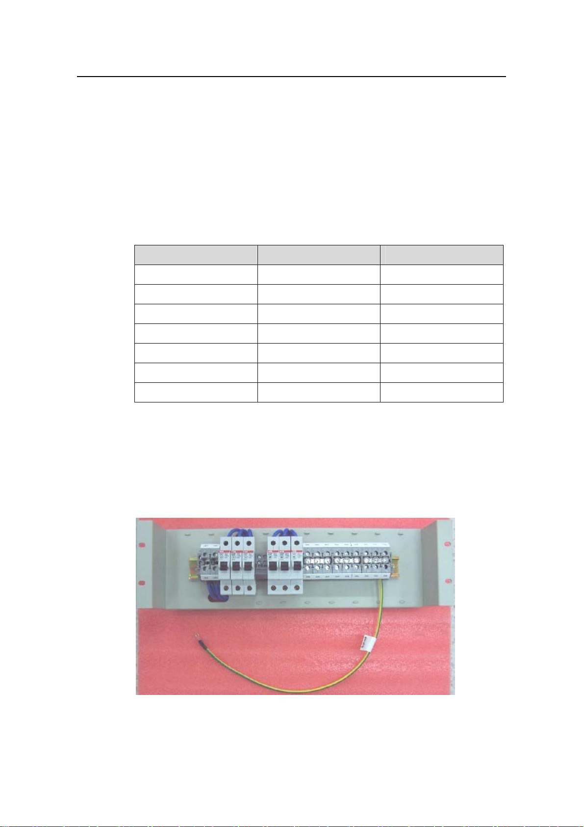
Installation Manual
H3C S9500 Series Routing Switches Chapter 4 Switch Installation
III. Electrical capacity of the terminal blocks
z Rated curre
z e: 600 V
Rated voltag
z Rated cross-sectional area: 16 mm
z Maximum current/maximum crimping area: 63 A/16 mm
nt: 63 A
2
2
IV. Terminal block components
Table 4-1illustrates terminal block components.
Table 4-1 Terminal block components
NO Name Quantity
1 End bracket 2
2 Cross connector 3
3 Marker 6
4 Terminal 11
5 Clapboard 7
6 Rail 1
7 Circuit breaker 6
4.7.2 Inst
allation of Power Distribution Box
To install power distribution box, take the following steps
z Install the DC input terminal blocks and ai
r switches to the cabinet via the rail, as
illustrated in Figure 4-24.
:
Figure 4-24 Install the DC input terminal blocks and air switches
4-21
Page 91

Installation Manual
H3C S9500 Series Routing Switches Chapter 4 Switch Installation
z Connect the DC input terminal blocks and th
fix the cable properly. Also use a 6mm
2
e air switches with 6mm2 cables and
cable for grounding, as illustrated in Figure
4-25.
Figure 4-25 Backplane Diagram for connecting DC input terminal blocks and air
switches
z
Fix the DC power distribution box onto the back of the cabinet, as illustrated in
Figure 4-26.
Figure 4-26 Diagram for fixing the power distribution box to the rear
z You can make the air switches to supply power to D
of the B68 cabinet
C power modules by
connecting the lower terminals of the air switches to DC powe r input terminals and
4-22
Page 92

Installation Manual
H3C S9500 Series Routing Switches Chapter 4 Switch Installation
supply voltages to DC power. (Refer to Figure 4-23 for detail. Note that the
2
diameter of the cables need to be 6mm
z an use the BGND and PGND terminal blocks as needed. The rightmost
You c
PGND terminals must be connected to the cabinet using a 6mm
or 10mm2.)
2
cable
s, as
illustrated in Figure 4-26.
z Fasten the connected power cables with a wire and secure them onto the p
ower
distribution box.
z Use two 16mm
You need to connect the two cables to the leftmost terminal blocks
2
cables to connect the cabinet and the DC power distribu
of the cabinet,
tion box.
as illustrated in Figure 4-23.
4.8 Inst
alling Cabling Rack
For your convenience, cabling racks are shipped with the S9500 series. T
following steps to install the rack.
Step 1: Face the LPU slots of the switch;
Step 2: Att ach the left mounting ear (the one with an elliptical hole o n one surfa
recessed hole on the other) onto the cabling rack and fix it with screws (one cabling
rack for S9505/S9508 and two for S9512);
Step 3: Install mounting ears onto the both sides of the switch.
Cabling rackCabling rack
ake the
e and a
c
Figure 4-27 The position of the cabling rack
alling Fan Tray 4.9 Inst
The fan tray is hot swappable.
4-23
Page 93

Installation Manual
H3C S9500 Series Routing Switches Chapter 4 Switch Installation
Caution:
In ca
se of bodily injuries, do not touch any naked wire, terminal or other parts of the
prod labels.
uct with hazardous voltage
Step 1: Wear the ESD-preventive wrist strap, making sure that it makes good skin
cont
act; take the fan tray out from the packing bag.
Step ection (just check the direction of instructional words,
2: Hold the fan tray in right dir
and if you insert it upside down, the pl
inside the chassis), with one han
ejector levers on the fan tray with both hands and pull them outward. Align the fan tray
with the guides in the chassis and slide it gently into the slot until its plug touches the
chassis socket.
ug of the fan tray cannot touch the right socket
d on its handle and the other hand at its bottom the
4.10 Inst
Step 3: Fasten the mounting screws on the p
Note:
The above installation steps are just for replacing your fan tray, since the fan tray is
delivered together with the chassis and no initial insta
anel of the fan tray with a screw driver.
llation is required.
alling LPU
The LPUs of the S9500 series are hot-swappable.
Step 1: W ear the ESD-preventive wrist strip, makin
Take the LPU out of the packing bag.
Step 2: Unscrew the mounting screws holding the blank filler p
you plan to install the LPU, and remove the pa
Step 3: Hold the ejector levers on the fan tray with both hands and pull them outward.
Align the LPU with the guides in the chas
positioning pin of the LPU touches the hole in the chassis.
sis and slide it gently into the slot until the
g sure that you have grounded it well.
anel in the slot where
nel from the slot.
Step 4: Pull the ejector le
Step 5: Fix the LPU by fastening
vers inward, locking the positioning pin into the hole.
the mounting screws on the LPU with a screw driver.
4-24
Page 94

Installation Manual
H3C S9500 Series Routing Switches Chapter 4 Switch Installation
te: No
Put the removed blank filler panel away for future use.
For the S9500 series, the service processor card can be installed in the LPU slot in the
same way as installing the LPU board.
4.11 Co
4.11.1 Co
I.
nnecting Interface Cables
nnecting Console Cable
Introduction
Console cable is an 8-core shielded cable. At one end of the cable is a crimped RJ-45
connector that is to be plugged into the console port of the switch. At the other end of
the cable is a DB
on the console terminal. The following figure illustrates the console cable.
Enlarged A side
Pos. 25
-9 (female) connector. You can plug it into the 9-pin (male) serial port
DB 25 Female
A
8P8C Plug
DB9 Female
B
Pos.1
Enlarged B side
Pos.8
Enlarged C side
Pos.1
Pos.1
C
Pos.9
Figure 4-28 Console cable
Table 4-2 Console cable pinouts
RJ-45 Signal DB-9 Signal
1 RTS 8 CTS
2 DTR 6 DSR
3 TXD 2 RXD
4 CD 5 SG
4-25
Page 95

Installation Manual
H3C S9500 Series Routing Switches Chapter 4 Switch Installation
RJ-45 Signal DB-9 Signal
5 GND 5 SG
6 RXD 3 TXD
7 DSR 4 DTR
8 CTS 7 RTS
II. Connecting console cable
Take the following
the terminal.
1) Plug the DB-9 female connector of the console cable into the serial port of the
PC/terminal where the switch is to be configured.
2) Connect the RJ-45 connector of the console cable to the console port of the
switch.
Note:
The PC serial port is not hot-swappable, so you are not allowed to insert or remov
console cable into or from the PC serial port.
When connecting the console cable, first connect the DB9 end to the PC serial p o
then the RJ45 end to the console port of the switch. And removing the console ca
just in inverse order.
When removing the console cable, first remove the RJ-45 end and then the DB9
4.11.2 Connectin
steps to connect the console cable, when configuring the switch on
e the
rt and
ble is
end.
g AUX Cable
You need an AUX cable when configuring the S9500 series with the remote m
dial-up approach.
odem
I. Introduction
AUX cable is an 8-core shielded cable. At one end of the cable is an RS-232-compliant
RJ-45 c r that can be into the AUX port of the switch. At end is
DB-9 (male) connector can plug it into ) port of the modem. For
detail, refer to Figure 4-28 and Table 4-2.
onnecto plugged the other
. You the DB-9 (female
II. Connecting AUX cable
1) Plug the RJ-45 con ctor of the AUX c ch.
ne able into the AUX port of the swit
4-26
Page 96

Installation Manual
H3C S9500 Series Routing Switches Chapter 4 Switch Installation
Plug the DB-9 (male) connector at the other end into the serial port of the analog
modem.
4.11.3 Connecting Category-5 Shielded Cable
I. I oduction to RJ-4 nector
ntr 5 con
4.11.4 Co
Being RJ-45 connecto 10Base-T/100B e-TX port of the S9500 series supports
MDI/MDIX auto-sensing and w
The following figure illustra
PIN #8
PIN #1
igure 4-29 RJ-45 connector
F
II ng category-5 shielded cable
. Connecti
Step 1: Plug one end of the network cab le into the desired Ethernet RJ-45 connector on
the switch.
Step 2: Plug the other end of the cable into the RJ-45 port of the peer device.
r, the as
ill be connected using the category-5 shielded cable.
tes an RJ-45 connector.
nnecting Fiber
Note:
All the megabit and gigabit optical modules available for the S9500 series are SFP
modules that provide LC user ports.
I. Introduction to fiber connector
4-27
Page 97

Installation Manual
H3C S9500 Series Routing Switches Chapter 4 Switch Installation
Note:
z When selecting a fiber network facility, make sure that the type of the connector and
the fiber match the adopted optical port.
z Before connecting the fiber, make sure that the receive-end optical power does not
exceed the upper threshold of th
e receiving optical power. Excessive receiving
optical power is very likely to burn the optical module.
Fiber connectors are indispensable pa
communication system. Their application a
optical channels, which makes the optical syste
convenient and the transit dispatching of t
connectors, only LC connector will be intr
z LC fiber connector
ssive components in an optical fiber
llows the removable connection between
m debugging and maintenance more
he system more flexible. Among various fiber
oduced here.
Figure 4-30 LC connector
II
. Connecting fiber
Step 1: Plug one en
tep 2: Connect the other end of the fiber into the corresponding device.
S
d of the fiber into the SFP optical module of the S9500 series.
Caution:
When the optical interface has not been connected with a fiber connector or its
d
ustproof mesh is open, there might be some invisible radiation emitted from the optical
interface. So do not look into the optical interface directly.
Cover the optical interface if there is
no connector plugged in.
4.12 Cable Routing Recommendations
4.12.1 Freestanding Switch on Tabletop
For only selling an integrated chassis, you do not have to care about the cabling inside
or outside the cabinet. All the LPU cables are routed from the left side of the chassis
4-28
Page 98

Installation Manual
H3C S9500 Series Routing Switches Chapter 4 Switch Installation
(along the
cabling channel), and the chassis power cords (AC/DC power cords) are
routed in the front of the chassis.
4.12.2 Cabin
et-Mounting Switch
If t
he switch is mounted in a 19-inch standard cabinet or B68-22 cabinet, the LPU
cab hassis and are routed up or
les are bound on the cabling rack at the lef t side of the c
down to pass through the chassis top or the raised floor depending on the available
e
quipment room condition (that is, the signal cables are routed into the chassis either
from the cabling rack on the chassis top or from the cabling trough under the floor) of
the exchange office. The power cords run along the left-front of the chassis and out of
the chassis either from the top or the raised floor depending on the equipment room
conditions (DC power distribution cabinet, lightning protection box, and terminal block,
etc.) of the exchange office.
4.13 Cable Management
4.13.1 Correct Labels
Before bundling the cables, you shoul
to the right position on the cables. For d
Appendix A Engineering Labels for Cables.
d fill in the labels for them correctly and stick them
etails, refer to the description of label usage in
4.13.2 Cable Management Requirements
Bundle and put the cables inside the cabinet in a straight and neat way. No
z
intertwinement or bending is allowed.
Intertwined
Intertwined
Figure 4-31 Cable bundling example I
Bent
Bent
4-29
Page 99

Installation Manual
H3C S9500 Series Routing Switches Chapter 4 Switch Installation
z The bending radius of cable body cannot be less than twice of the cable diameter.
The bending radius of the cab
le cannot be less than 5 times of its diameter at the
place where it is led out of the connector;
z Different cables (power co
rd, signal cable, PGND wire, etc.) should be cabled and
bundled separately rather than together in the cabinet. If they are close to each
other, you can cable them in cross-shape. For parallel cabli ng, the space between
power cord and signal cable should be no less than 30 mm (1.2 in);
z The cable binding rack and cabling ch annel in sid e an d out side the cabi net shoul d
be smooth and without sharp edges or tips;
z The metal cable management hole should have a smooth and fully rounded
surface or wear a insulating bush;
z Use the right type of ties to bundle the cables. Do not bundle cables with joined
ties. The following types of ties are available currently: 100 × 2.5 mm (3.9 in × 0.1
in), 150 × 3.6 mm (5.9 × 0.1 in), 300
0.4 in), and 580 × 13 m
z Cut the extra parts of th
angular tips
. See the following figure:
m (22.8 × 0.5 in);
e ties neatly after bundling the cables, leaving no sharp or
× 3.6 mm (11.8 × 0.1 in), 530 × 9 mm (20.9 ×
Figure 4-32 Cable bundling example II
z Bundle the cables wherever cable bending cannot be avoided. Ho
ties cannot be placed inside the bending area in case of the likel
core break due to excessive stress. See the following figure.
4-30
wever, the cable
ihood of cable
Page 100

Installation Manual
H3C S9500 Series Routing Switches Chapter 4 Switch Installation
re 4-33 Cable bundling example III
Figu
z
The spare cables or excessive cable parts should be folded and bundled and
placed at a right place in the cabinet or on the cabling channel. A “right place”
refers to the place where the cables will n
ot affect the operation of the device or
impair the device, or be damaged;
z guides of any mobile components;
The power cords cannot be tied on the
z Reserve some redundancy for the cables connectin
PGND wire of the door for example, to free the cables
mobile part should be installed in such a way that the extra cable segme
kept from contacting the heat source, sharp points or edges. Use hi
g to the mobile parts, the
from possible stress. Such a
nts will be
gh temperature
cables near the heat sources;
z For the cable terminals fixed using screw threads, the screws or
securely fastened and prevented from loosing. See the followi
nuts should be
ng figure;
Flat Flat Spring
Flat Flat Spring
washer washer washer
washer washer washer
Nut
Nut
Figure 4-34 Cable fixing example
z When using a hard power cord, fix it near its terminal so as to free the terminal and
the cable from stress;
z Do not use tapping screws to fasten the connecting terminals;
4-31
 Loading...