

H3C S7500E Series, S7502E, S7503-S, S7506E (non-PoE), S7506E-S Installation, Quick Start
...
New H3C Technologies Co., Ltd.
http://www.h3c.com.hk
Document version: 6PW102-20170430
H3C S7500E Switch Series
Installation Quick Start

Copyright © 2015-2017, New H3C Technologies Co., Ltd. and its licensors
All rights reserved
No part of this manual may be reproduced or transmitted in any form or by any means without prior
written consent of New H3C Technologies Co., Ltd.
Trademarks
H3C, , H3CS, H3CIE, H3CNE, Aolynk, , H
3
SecEngine, SecPath, SecCenter, SecBlade, Comware, ITCMM and HUASAN are trademarks of New
H3C Technologies Co., Ltd.
All other trademarks that may be mentioned in this manual are the property of their respective owners
Notice
The information in this document is subject to change without notice. Every effort has been made in the
preparation of this document to ensure accuracy of the contents, but all statements, information, and
recommendations in this document do not constitute the warranty of any kind, express or implied.
Environmental protection
This product has been designed to comply with the environmental protection requirements. The storage,
use, and disposal of this product must meet the applicable national laws and regulations.
Care, , IRF, NetPilot, Netflow,

Contents
Installation quick start ·················································································································································· 1
Chassis views and technical specifications ···················································································································· 1
Chassis views ···························································································································································· 1
Technical specifications ··········································································································································· 2
Safety recommendations ·················································································································································· 4
Examining the installation site ········································································································································· 5
Installing the switch ··························································································································································· 5
Attaching the slide rails to the rack ························································································································ 5
Installing cage nuts ··················································································································································· 6
Installing mounting brackets and cable management brackets ··········································································· 8
Installing the switch in the rack ······························································································································· 9
Grounding the switch ············································································································································ 10
Installing FRUs ························································································································································ 11
Installing a power module ···································································································································· 12
Connecting power cords ······································································································································ 14
Accessing the switch for the first time ·························································································································· 18
Connecting the console cable ······························································································································ 18
Setting terminal parameters ·································································································································· 18
Powering on the switch ········································································································································· 19
Obtaining documentation ············································································································································· 20
Index ··········································································································································································· 21
i
Installation quick start
This installation quick start provides basic instructions for installing an S7500E switch. For more
information about the installation procedure, see H3C S7500E Switch Series Installation Guide.
The installation procedure is similar for all S7500E switch models. This installation quick start uses the
S7503E switch as an example.
NOTE:
The figures in this installation quick start are for illustration only.
Chassis views and technical specifications
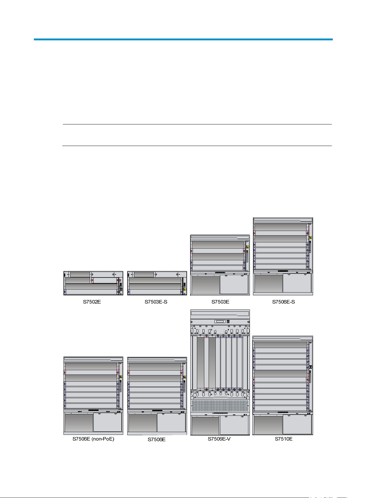
Chassis views
Figure 1 Chassis
1

Figure 2 S7503E switch front panel
g
Dep
p
p
(1) MPU slots (2) LPU slots
(3) Power module slots (4) Fan tray slot
Technical specifications
Table 1 Chassis dimensions
Model Hei
S7502E 175 mm (6.89 in) (4 RU) 436 mm (17.17 in) 420 mm (16.54 in)
S7503-S 175 mm (6.89 in) (4 RU) 436 mm (17.17 in) 420 mm (16.54 in)
S7503E 441 mm (17.36 in) (10 RU) 436 mm (17.17 in) 420 mm (16.54 in)
S7506E-S 575 mm (22.64 in) (13 RU) 436 mm (17.17 in) 420 mm (16.54 in)
S7506E (non-PoE) 575 mm (22.64 in) (13 RU) 436 mm (17.17 in) 420 mm (16.54 in)
S7506E 575 mm (22.64 in) (13 RU) 436 mm (17.17 in) 420 mm (16.54 in)
S7506E-V 930 mm (36.61 in) (21 RU) 436 mm (17.17 in) 420 mm (16.54 in)
S7510E 708 mm (27.87 in) (16 RU) 436 mm (17.17 in) 420 mm (16.54 in)
ht Width
th
Table 2 Power module specifications
Model Rated voltage range
PSR320-A
PSR320-D –48 VDC to –60 VDC 300 W No N/A
100 VAC to 240 VAC @
50/60Hz
Maximum output
ower
300 W No N/A
Support for PoE
Maximum PoE
ut power
out
PSR650-A
PSR650-D –48 VDC to –60 VDC 650 W No N/A
100 VAC to 240 VAC @
50/60Hz
650 W No N/A
2

Model Rated voltage range
p
p
Maximum output
ower
Support for PoE
Maximum PoE
ut power
out
PSR650C-12A
PSR650C-12D –48 VDC to –60 VDC 650 W No N/A
PSR1400-A
PSR1400-D –48 VDC to –60 VDC 1400 W Yes 6720 W
PSR1400-12D1 –48 VDC to –60 VDC 1400 W No N/A
PSR2800-ACV
100 VAC to 240 VAC @
50/60Hz
100 VAC to 240 VAC @
50/60Hz
100 VAC to 240 VAC @
50/60Hz
650 W No N/A
1150 W (110
VAC)
1400 W (220
VAC)
1150 W (110
VAC)
1400 W (220
VAC)
No N/A
No N/A
Yes 1150 W
Yes 1400 W
• One PoE input:
1150 W (110
VAC)
Yes
• Two PoE inputs:
• Three PoE
PSR6000-ACV
100 VAC to 240 VAC @
50/60Hz
1400 W (220
VAC)
Yes
• One PoE input:
• Two PoE inputs:
• Three PoE
1200 W
2400 W
inputs: 3600 W
1800 W
3600 W
inputs: 5300 W
Table 3 Power module and chassis compatibility matrix
Chassis
Power module
S7502E
PSR320-A
PSR320-D
PSR650-A
PSR650-D
PSR650C-12A — —
PSR650C-12D — —
PSR1400-A — —
PSR1400-D — —
PSR1400-12D1 — —
PSR2800-ACV — —
z
z
z
z
S7503E
-S
z
z
z
z
S7503
E
— — — — — —
— — — — — —
{
{
z
z
z
z
z
z
3
S7506E
{
{
z
z
z
z
z
z
S7506E
-S
{
{
—
—
z
z
z
z
S7506E
(non-PoE)
{
{
z
z
z
z
z
—
S7506E
-V
{
{
z
z
z
z
z
z
S7510
E
—
—
z
z
z
z
z
z
Chassis
Power module
S7502E
PSR6000-ACV — —
S7503E
-S
S7503
E
z
NOTE:
• "z" indicates that the power module can be directly installed on the chassis.
• "{" indicates that you must first install a power module adapter on the chassis and then install the power
module on the power module adapter.
• "—" indicates that the power module cannot be installed on the chassis.
Safety recommendations
To avoid equipment damage or bodily injury caused by improper use, read the following safety
recommendations before installation. Note that the recommendations do not cover every possible
hazardous condition.
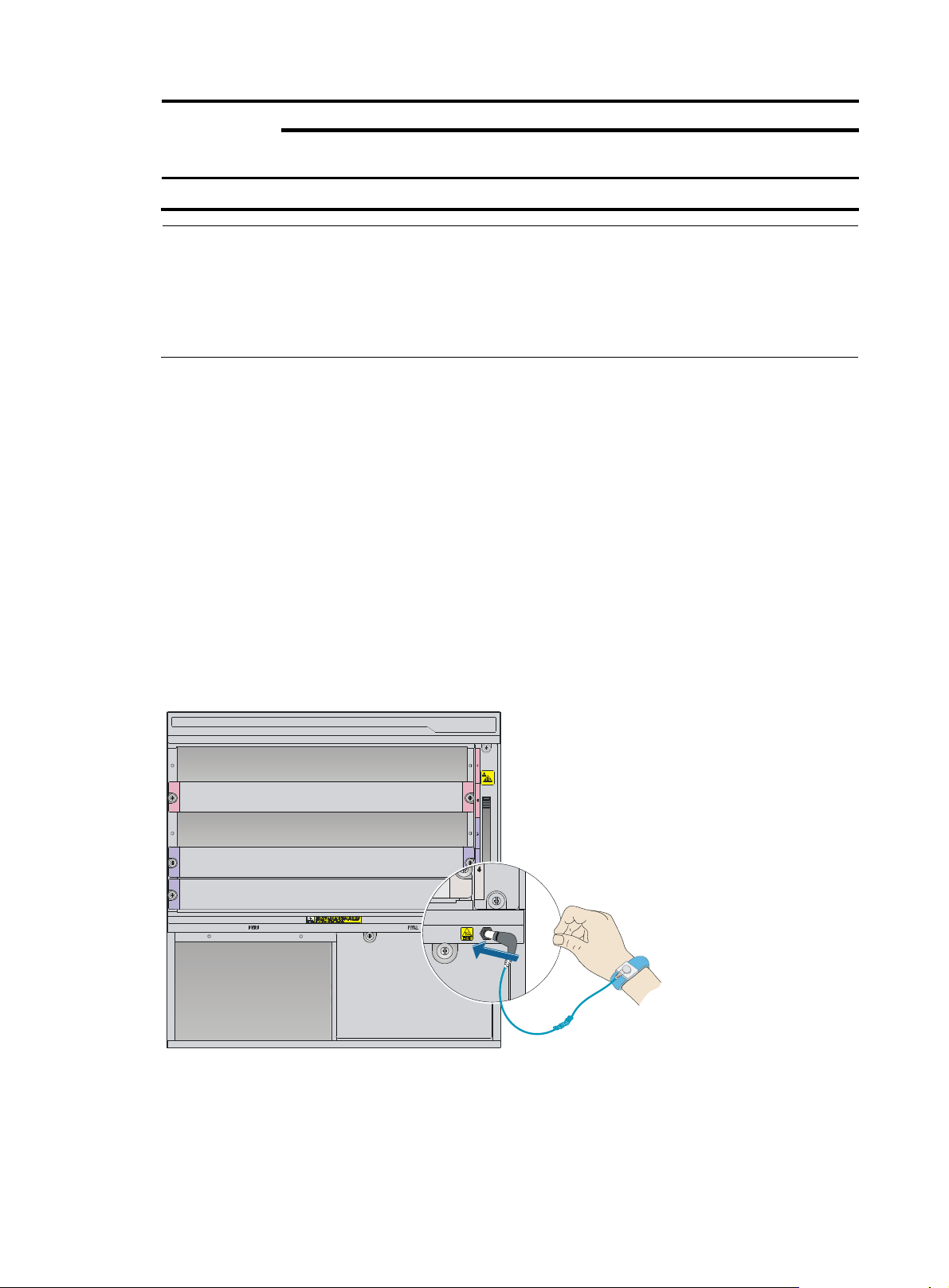
• To prevent ESD damage, always wear an ESD wrist strap and make sure it is reliably grounded
before you touch the switch, cards, or PCB.
• Do not install the switch, FRUs, or cables when the switch is powered on.
S7506E
z
S7506E
-S
z
S7506E
(non-PoE)
—
S7506E
-V
z
S7510
E
z
• To avoid equipment damage or bodily injury, make sure the switch is reliably grounded before
powering on the switch.
• To ensure good ventilation, install a blank filler panel in an unused slot.
Figure 3 Attaching an ESD wrist strap
4
 Loading...