

Page 1

H3C S7500E Series Ethernet Switches
Installation Manual
Hangzhou H3C Technologies Co., Ltd.
http://www.h3c.com
Manual Version: T2-080406-20090526-C-1.06
Page 2

Copyright © 2007-2009, Hangzhou H3C Te chnologie s Co., Ltd . and it s licen sors
All Rights Reserved
No part of this manual may be reproduced or transmitted in any form or by any means without prior
written consent of Hangzhou H3C Technologies Co., Ltd.
Trademarks
H3C, , Aolynk, , H3Care,
SecPro, SecPoint, SecEngine, SecPath, Comware, Secware, Storware, NQA, VVG, V
XGbus, N-Bus, TiGem, InnoVision and HUASAN are trademarks of Hangzhou H3C Technologies Co.,
Ltd.
All other trademarks that may be mentioned in this manual are the property of their respective owners.
Notice
The information in this document is subject to change without notice. Every effort has been made in the
preparation of this document to ensure accuracy of the contents, but all statements, information, and
recommendations in this document do not constitute the warranty of any kind, express or implied.
Technical Support
customer_service@h3c.com
http://www.h3c.com
, TOP G, , IRF, NetPilot, Neocean, NeoVTL,
2
G, VnG, PSPT,
Page 3

About This Manual
Organization
H3C S7500E Series Ethernet Switches Installation Manual is organized as follows:
Chapter Contents
1 Product Overview
2 Installation Preparations
3 Hardware Installation
4 System Commissioning
5 Hardware Maintenance
6 Software Maintenance
7 Troubleshooting
Appendix A List of Pluggable
Optical Modules
Appendix B AC Power Cables
Used in Different Countries or
Regions
Introduces the H3C S7500E Series Ethernet Switches in terms of
chassis, SRPUs, LPUs, power supply, and fan tray.
Specifies the installation requirements of the H3C S7500E Series
Ethernet Switches and presents installation precautions.
Introduces how to install the H3C S7500E Series Ethernet
Switches and how to connect the power supply, ground cables,
and the console cable.
Introduces the startup process of the H3C S7500E Series
Ethernet Switches, including power-on and system initialization.
Introduces how to install and remove power modules, cards, fans,
mounting ears, cable management bracket, CF card, and air filters
of the H3C S7500E Series Ethernet Switches.
Introduces how to load and upgrade the software of the H3C
S7500E Series Ethernet Switches.
Introduces how to troubleshoot the configuration system, power
modules, fans, and LPUs of the H3C S7500E Series Ethernet
Switches.
Introduces pluggable optical modules for different types of ports
and their related parameters.
Introduces AC power cables used in different countries or
Regions, including 10A AC power cables and 16A AC power
cables.
Appendix C Compliance and
Safety Manual
Conventions
The manual uses the following conventions:
Command conventions
Convention Description
Boldface
italic
[ ] Items (keywords or arguments) in square brackets [ ] are optional.
{ x | y | ... }
[ x | y | ... ]
{ x | y | ... } *
Provides Compliance and safety manual
The keywords of a command line are in Boldface.
Command arguments are in italic.
Alternative items are grouped in braces and separated by vertical bars.
One is selected.
Optional alternative items are grouped in square brackets and
separated by vertical bars. One or none is selected.
Alternative items are grouped in braces and separated by vertical bars.
A minimum of one or a maximum of all can be selected.
Page 4
Convention Description
[ x | y | ... ] *
&<1-n>
# A line starting with the # sign is comments.
Optional alternative items are grouped in square brackets and
separated by vertical bars. Many or none can be selected.
The argument(s) before the ampersand (&) sign can be entered 1 to n
times.
GUI conventions
Convention Description
< > Button names are inside angle brackets. For example, click <OK>.
[ ]
/
Window names, menu items, data table and field names are inside
square brackets. For example, pop up the [New User] window.
Multi-level menus are separated by forward slashes. For example,
[File/Create/Folder].
Symbols
Convention Description
Related Documentation
In addition to this manual, each H3C S7500E Series Ethernet Switches documentation set includes the
following:
Manual Description
H3C S7500E Series Ethernet
Switches Operation Manual
H3C S7500E Series Ethernet
Switches Command Manual
Means reader be extremely careful. Improper operation may cause
bodily injury.
Means reader be careful. Improper operation may cause data loss or
damage to equipment.
Means a complementary description.
It guides users how to use H3C S7500E Series Ethernet
Switches.
It provides detailed descriptions of the commands available on
H3C S7500E Series Ethernet Switches.
Page 5

Obtaining Documentation
You can access the most up-to-date H3C product documentation on the World Wide Web at this URL:
http://www.h3c.com.
The following are the columns from which you can obtain different categories of product documentation:
[Products & Solutions]: Provides information about products and technologies, as well as solutions.
[Technical Support & Document > Technical Documents]: Provides several categories of product
documentation, such as installation, configuration, and maintenance.
[Technical Support & Document > Software Download]: Provides the documentation released with the
software version.
Documentation Feedback
You can e-mail your comments about product documentation to info@h3c.com.
We appreciate your comments.
Environmental Protection
This product has been designed to comply with the requirements on environmental protection. For the
proper storage, use and disposal of this product, national laws and regulations must be observed.
Page 6

Table of Contents
1 Product Overview······································································································································1-1
Introduction ·············································································································································1-1
Physical Description of the S7500E Series·····························································································1-1
Chassis and Slots····························································································································1-1
Backplane······································································································································1-10
Power Supply System ···················································································································1-10
Fan Tray ········································································································································1-19
Air Filter ·········································································································································1-20
SRPUs ··················································································································································1-20
SRPU Types··································································································································1-20
LSQ1MPUA0 SRPU······················································································································1-21
Dedicated S7503E-S SRPU-LSQ1CGP24TSC0 ··········································································1-25
Dedicated S7503E-S SRPU-LSQ1CGV24PSC0··········································································1-29
Salience VI-10GE SRPU-LSQ1SRP2XB0 ····················································································1-33
Salience VI-Smart SRPU-LSQ1SRPA0 ························································································1-37
Salience VI SRPU-LSQ1SRPB0 ···································································································1-40
Salience VI-Turbo SRPU-LSQ1SRP1CB0····················································································1-43
Salience VI-Lite SRPU-LSQ1MPUB0 ···························································································1-46
Salience VI-Plus SRPU-LSQ1SRPD0···························································································1-49
Salience VI-GE SRPU-LSQ1SRP12GB0······················································································1-52
LPUs······················································································································································1-56
LSQ1FP48SA0 ······························································································································1-56
LSQ1FV48SA0 ······························································································································1-57
LSQ1GP12EA0 ·····························································································································1-58
LSQ1GP12SC0 ·····························································································································1-58
LSQ1GP24SC0 ·····························································································································1-59
LSQ1GP48SC0 ·····························································································································1-60
LSQ1GP48SD0 ·····························································································································1-61
LSQ1GP48EB0 ·····························································································································1-62
LSQ1GT24SC0 ·····························································································································1-63
LSQ1GV24PSC0···························································································································1-64
LSQ1GV48SA0 ·····························································································································1-66
LSQ1GV48SC0 ·····························································································································1-66
LSQ1GV48SD0 ·····························································································································1-67
LSQ1P24XGSC0···························································································································1-68
LSQ1T24XGSC0···························································································································1-69
LSQ1TGX1EA0 ·····························································································································1-70
LSQ1TGX2SC0·····························································································································1-71
LSQ1TGX2SD0·····························································································································1-72
LSQ1TGX2EB0 ·····························································································································1-73
LSQ1TGX4SD0·····························································································································1-74
LSQ1TGX4EB0 ·····························································································································1-75
LSQ1TGX8SD0·····························································································································1-76
i
Page 7

LSQ1GP24TSC0···························································································································1-76
LSQ1GP24TSD0···························································································································1-78
LSQ1GP24TEB0 ···························································································································1-79
LSQ1GP24TXSD0·························································································································1-81
LSQ1GV40PSC0···························································································································1-83
LSQ1PT4PSC0 ·····························································································································1-84
LSQ1PT8PSC0 ·····························································································································1-85
LSQ1PT16PSC0 ···························································································································1-86
LSQ2FP48SA0 ······························································································································1-87
LSQ2FT48SA0 ······························································································································1-88
Ordering Information for the S7500E Series·························································································1-89
Purchasing a Switch······················································································································1-89
Purchasing SRPUs························································································································1-90
Purchasing LPUs···························································································································1-91
Purchasing Optical Modules··········································································································1-92
Purchasing Air Filters ····················································································································1-92
Purchasing Fan Trays ···················································································································1-92
Purchasing PoE Modules ··············································································································1-92
ii
Page 8
1 Product Overview
Introduction
The S7500E Series Ethernet Switches (hereinafter referred to as the S7500E series) are high
performance, cost-effective Layer-3 switches with a large capacity. The S7500E series are designed to
operate at the core layer of small- and medium-sized networks, the convergence layer of large
enterprise networks, and the convergence and access layers of metropolitan area networks (MANs).
The S7500E series have been optimized to meet users’ diversified demands for devices used on these
networks.
The S7500E series include seven models, as described in
Table 1-1 Dimensions of the S7500E series
Model Slot direction Number of slots Number of SRPU slots
S7502E Horizontal 4 2 (half-sized slots)
S7503E-S Horizontal 3 1
S7503E Horizontal 5 2
S7506E-S Horizontal 8 2
S7506E Horizontal 8 2
S7510E Horizontal 12 2
S7506E-V Vertical 8 2
Table 1-1.
Physical Description of the S7500E Series
Chassis and Slots
The integrated chassis of the S7500E series consists of a card area, a fan area, and a power supply
area.
Table 1-2 Dimensions of the S7500E series
Model Dimensions (H × W × D)
S7502E 175 × 436 × 420 mm (6.89 × 17.17 × 16.54 in.)
S7503E-S 175 × 436 × 420 mm (6.89 × 17.17 × 16.54 in.)
S7503E 441 × 436 × 420 mm (17.36 × 17.17 × 16.54 in.)
S7506E-S 575 × 436 × 420 mm (22.64 × 17.17 × 16.54 in.)
S7506E 575 × 436 × 420 mm (22.64 × 17.17 × 16.54 in.)
1-1
Page 9
Model Dimensions (H × W × D)
S7510E 708 × 436 × 420 mm (27.87 × 17.17 × 16.54 in.)
S7506E-V 930 × 436 × 420 mm (36.61 × 17.17 × 16.54 in.)
z The backplane, switching & routing processing unit (SRPU), power modules, and fan tray are all
required parts of the S7500E series.
z SRPUs and line processing units (LPUs) are distinguished by their edge colors. SRPUs have pink
edges while LPUs have purple edges. SRPUs must be inserted in pink slots while LPUs must be
inserted in purple slots.
z The power supply of the S7500E series can be AC or DC, depending on the actual requirement.
However, it is forbidden to insert different power modules into one S7500E Ethernet switch.
S7502E
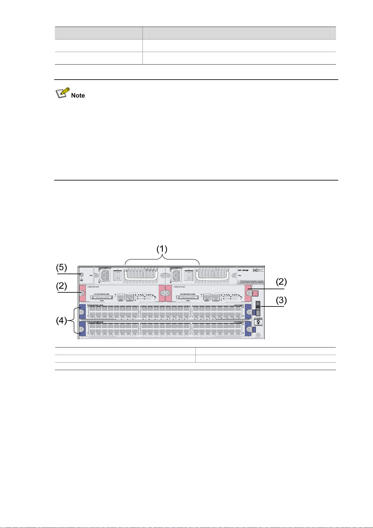
Figure 1-1 shows the front panel of the S7502E.
Figure 1-1 Front panel of the S7502E
(1) Power modules (2) SRPUs (in slot 0 and slot 1)
(3) Fan tray (4) LPUs (in slot 2 and slot 3)
(5) Jack for ESD-preventive wrist strap
All modules of the S7502E are hot swappable.
z The S7502E has four horizontal slots. SRPUs are inserted into the upper two slots. See callout 2 in
Figure 1-1. SRPUs are required and support active-standby switchover. Different LPUs are
inserted into the other two slots. See callout 4 in
z The fan tray is installed on the right side of the chassis. See callout 3 in Figure 1-1.
z The two power modules, which sit in the upper part of the chassis, provide 1+1 redundancy backup
and support dual power supply inputs. See callout 1 in
Figure 1-1.
Figure 1-1. You can select either AC power
supply or DC power supply.
1-2
Page 10
Throughout this chapter, the dual power supply inputs for an S7500E series switch must be the same in
voltage and frequency.
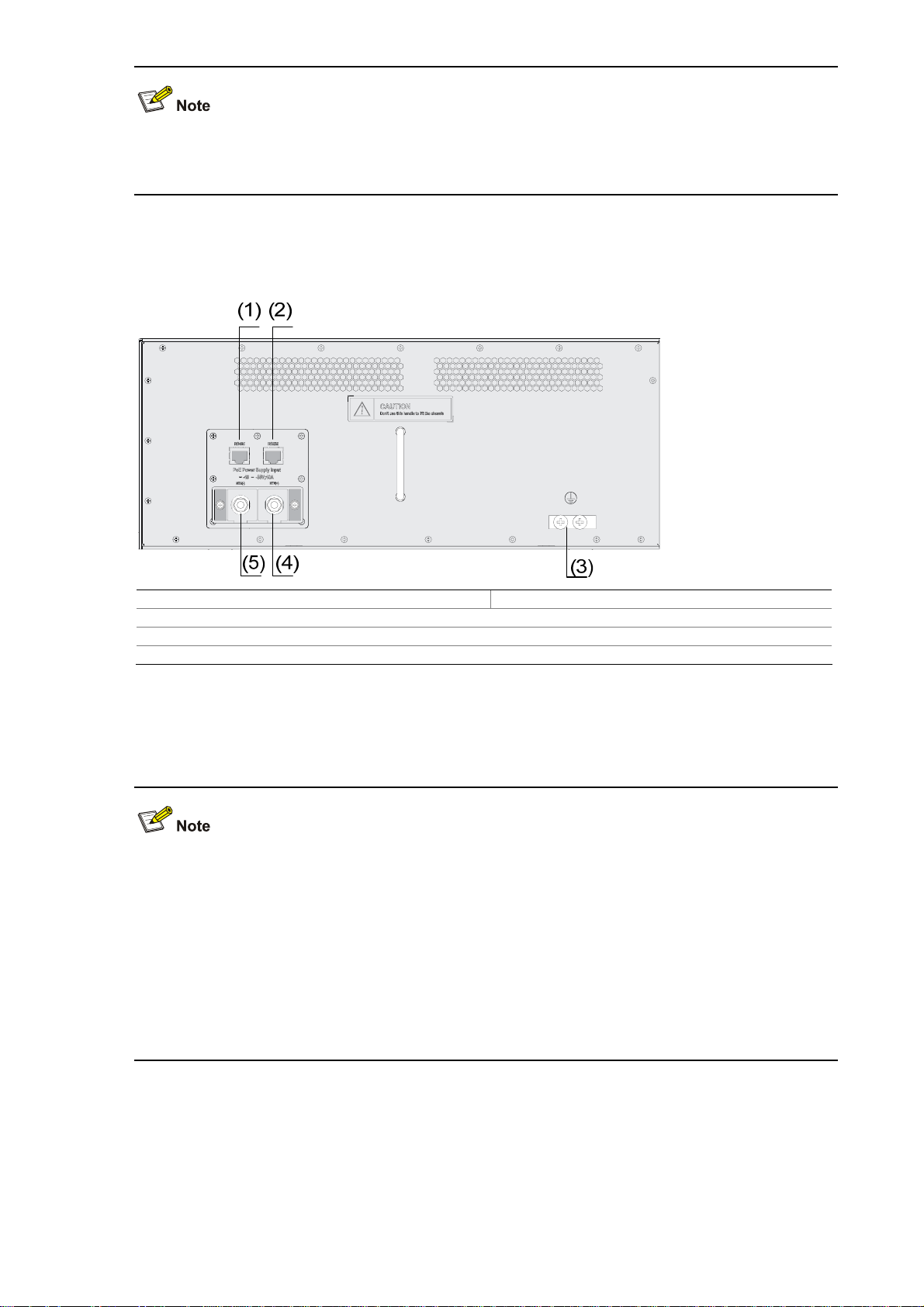
Figure 1-2 shows the rear panel of the S7502E.
Figure 1-2 Rear panel of the S7502E
(1) COM port for monitoring PoE (RS485) (2) COM port for monitoring PoE (RS232)
(3) Grounding screws
(4) RTN terminal (+) of external PoE power supply
(5) Negative terminal (–) of external PoE power supply (–46 V to –55 V)
There are two DC power input (PoE power supply input) terminals and two COM ports (monitor ports)
on the rear panel of the chassis.
z The S7500E series except the S7506E-S are Power over Ethernet (PoE) capable, that is, they can
supply power to devices such as IP phones, wireless access points, and network cameras
connected to their Ethernet ports through twisted pair cables.
z For the S7502E and S7503E-S, the external PoE power supply is connected to the PoE power
supply input terminals on the rear panel, while for the other models of the S7500E series, the
external PoE power supply is connected to a power module. For details, refer to section
PSR1400-D” on page 1-15, section“PSR2800-ACV” on page 1-16 and section PSR6000-ACV on
“
1-17.
page
S7503E-S
Figure 1-3 shows the front panel of the S7503E-S.
1-3
Page 11
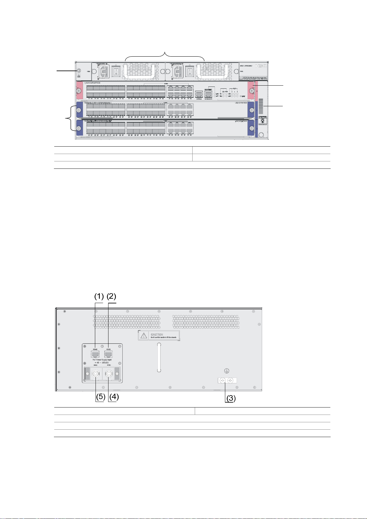
Figure 1-3 Front panel of the S7503E-S
(1)
(5)
(2)
(3)
(4)
(1) Power modules (2) SRPUs (in slot 0)
(3) Fan tray (4) LPUs (in slot 1 and slot 2)
(5) Jack for ESD-preventive wrist strap
All modules of the S7503E-S are hot swappable.
z The S7503E-S has three horizontal slots. The SRPU is inserted into the upper slot. See callout 2 in
Figure 1-3. The dedicated S7503E-S SRPU is required. Different LPUs are inserted into the other
two slots. See callout 4 in
z The fan tray is installed on the right side of the chassis. See callout 3 in Figure 1-3.
z The two power modules, which sit in the upper part of the chassis, provide 1+1 redundancy backup
and support dual power supply inputs. See callout 1 in
Figure 1-3.
Figure 1-3. You can select either AC power
supply or DC power supply.
Figure 1-4 shows the rear panel of the S7503E-S.
Figure 1-4 Rear panel of the S7503E-S
(1) COM port for monitoring PoE (RS485) (2) COM port for monitoring PoE (RS232)
(3) Grounding screws
(4) RTN terminal (+) of external PoE power supply
(5) Negative terminal (–) of external PoE power supply (–46 V to –55 V)
There are two DC power input (PoE power supply input) terminals and two COM ports (monitor ports)
on the rear panel of the chassis.
1-4
Page 12
S7503E
Figure 1-5 shows the front panel of the S7503E.
Figure 1-5 Front panel of the S7503E
(1)
(5)
(4)
(2)
(3)
(1) Fan tray (2) Jack for ESD-preventive wrist strap
(3) Power modules (4) LPUs (in slot 2 to slot 4)
(5) SRPUs (in slot 0 and slot 1)
All the modules of the S7503E are hot swappable.
z The S7503E has five horizontal slots. SRPUs are inserted into the upper two slots (see callout 5 in
Figure 1-5). SRPUs are required and support active-standby switchover. Different LPUs are
inserted into the other three slots (see callout 4 in
z The fan tray is installed on the right side of the chassis (see callout 1 in Figure 1-5).
z The two power modules, which sit in the lower part of the chassis (see callout 3 in Figure 1-5),
provide 1+1 redundancy backup and support dual power supply inputs. You can select either AC
power supply or DC power supply.
Figure 1-5).
(3)
S7506E-S
Figure 1-6 shows the front panel of the S7506E-S.
1-5
Page 13
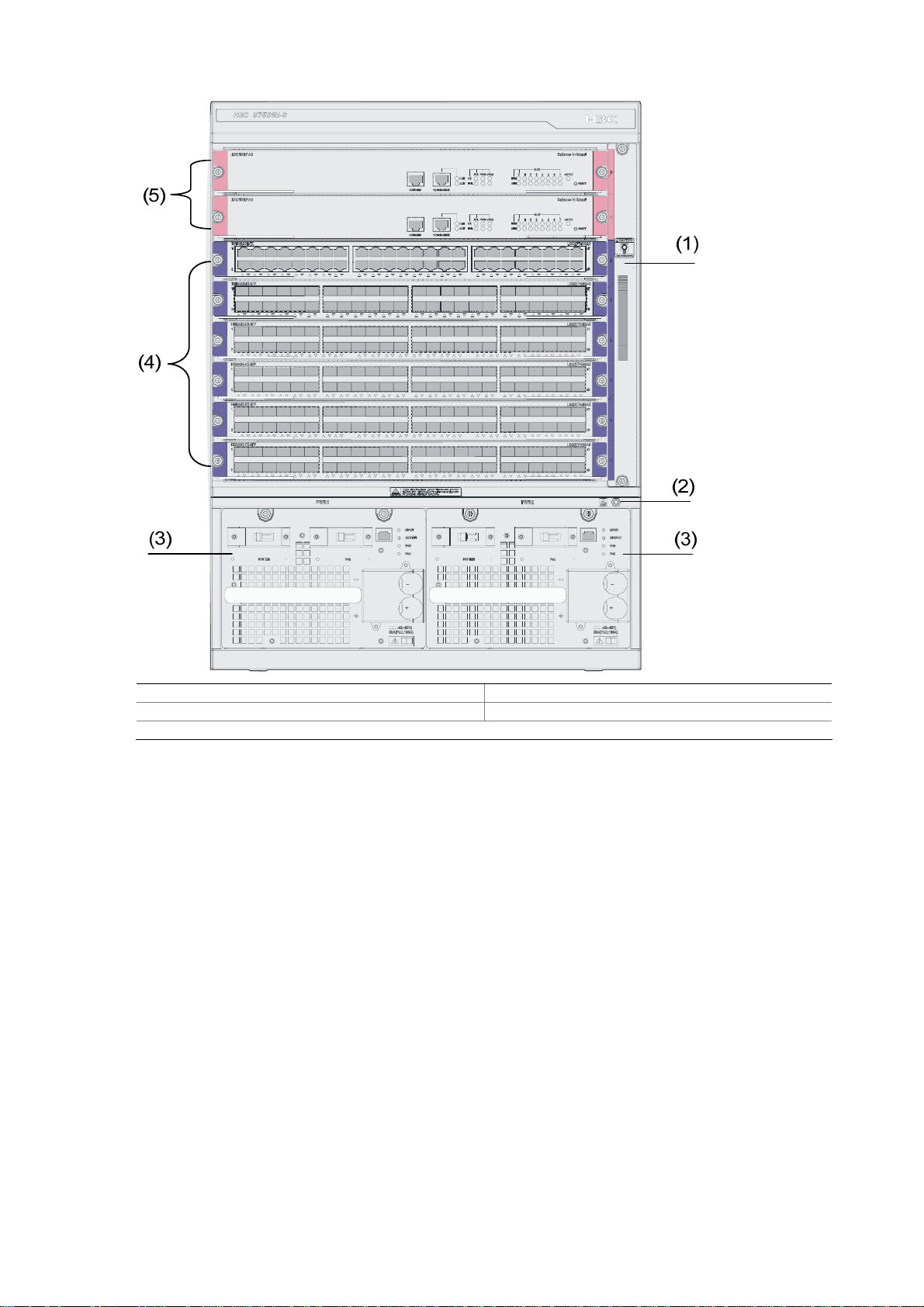
Figure 1-6 Front panel of the S7506E-S
(1) Fan tray (2) Jack for ESD-preventive wrist strap
(3) Power module (4) LPUs (in slot 2 to slot 7)
(5) SRPUs (in slot 0 and slot 1)
All the modules of the S7506E-S are hot swappable.
z The S7506E-S has eight horizontal slots. SRPUs are inserted in the upper two slots (see callout 5
Figure 1-6). SRPUs are required and support active-standby switchover. Different LPUs are
in
inserted into the other six slots (see callout 4 in
z The fan tray is installed on the right side of the chassis (see callout 1 Figure 1-6).
z The two power modules, which sit in the lower part of the chassis (see callout 3 in Figure 1-6),
Figure 1-6).
provide 1+1 redundancy backup and support dual power supply inputs. You can select either AC
power supply or DC power supply.
S7506E
Figure 1-7 shows the front panel of the S7506E.
1-6
Page 14
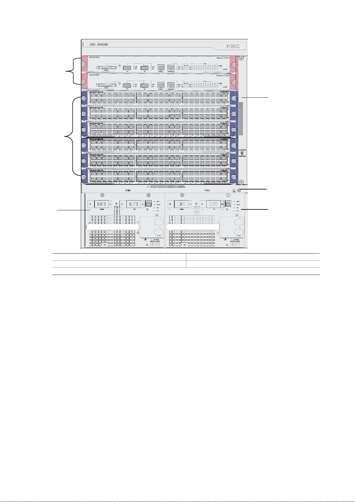
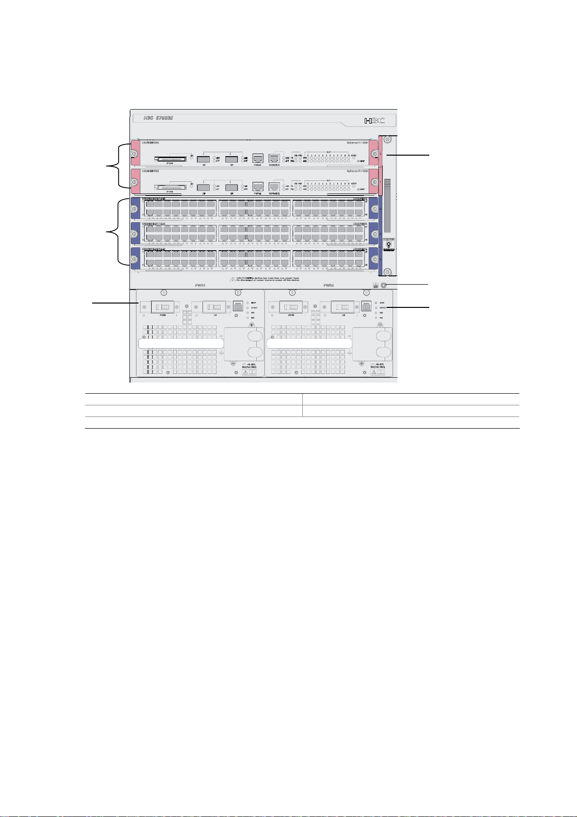
Figure 1-7 Front panel of the S7506E
(5)
(1)
(4)
(2)
(3)
(3)
(1) Fan tray (2) Jack for ESD-preventive wrist strap
(3) Power module (4) LPUs (in slot 2 to slot 7)
(5) SRPUs (in slot 0 and slot 1)
All the modules of the S7506E are hot swappable.
z The S7506E has eight horizontal slots. SRPUs are inserted in the upper two slots (see callout 5 in
Figure 1-7). SRPUs are required and support active-standby switchover. Different LPUs are
inserted into the other six slots (see callout 4 in
z The fan tray is installed on the right side of the chassis (see callout 1 Figure 1-7).
z The two power modules, which sit in the lower part of the chassis (see callout 3 in Figure 1-7),
Figure 1-7).
provide 1+1 redundancy backup and support dual power supply inputs. You can select either AC
power supply or DC power supply.
S7510E
Figure 1-8 shows the front panel of the S7510E.
1-7
Page 15
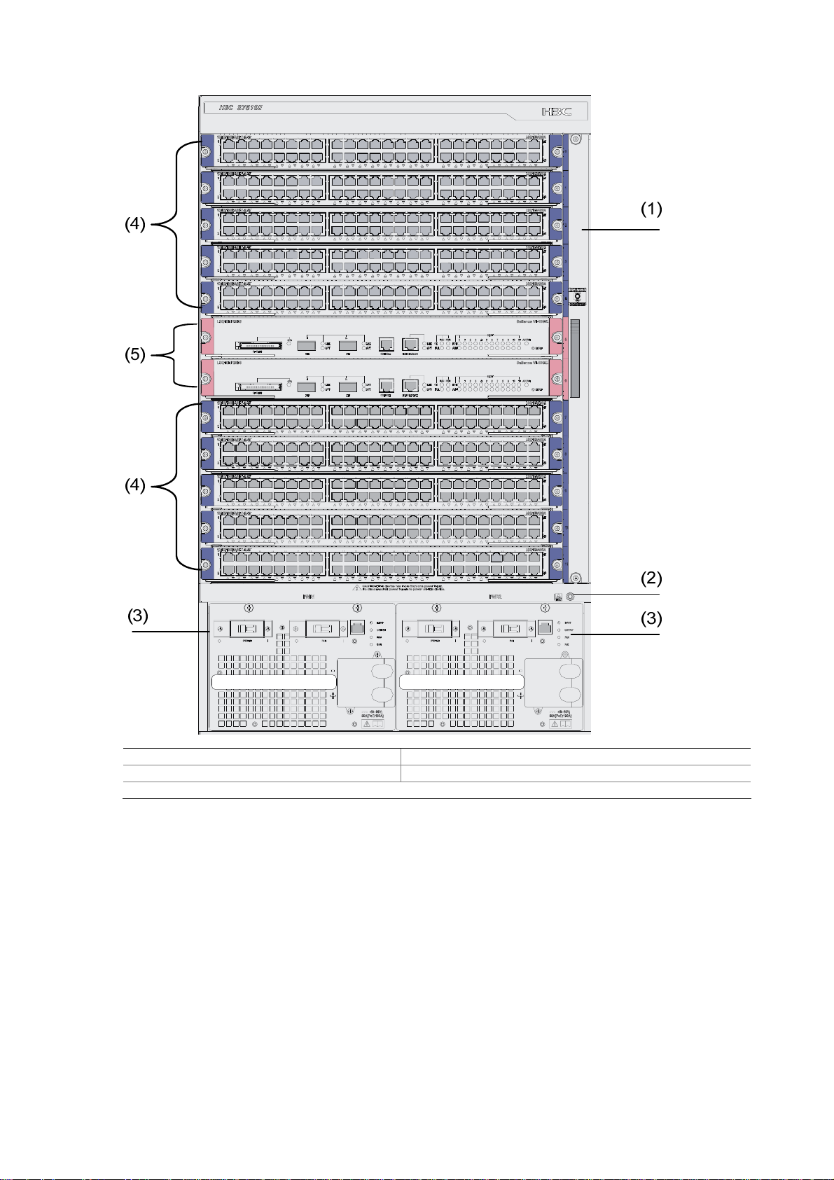
Figure 1-8 Front panel of the S7510E
(1) Fan tray (2) Jack for ESD-preventive wrist strap
(3) Power module (4) LPUs (in slot 0 to slot 4 and slot 7 to slot 11)
(5) SRPUs (in slot 5 and slot 6)
All the modules of the S7510E are hot swappable.
z The S7510E has twelve horizontal slots. SRPUs are inserted in the middle two slots (see callout 5
Figure 1-8). SRPUs are required and support active-standby switchover. Different LPUs are
in
inserted in the other ten slots (see callout 4 in
z The fan tray is installed on the right side of the chassis (see callout 1 in Figure 1-8).
z The two power modules, which sit in the lower part of the chassis (see callout 3 in Figure 1-8),
Figure 1-8).
provide 1+1 redundancy backup and support dual power supply inputs. You can select either AC
power supply or DC power supply.
S7506E-V
Figure 1-9 shows the front panel of the S7506E-V.
1-8
Page 16
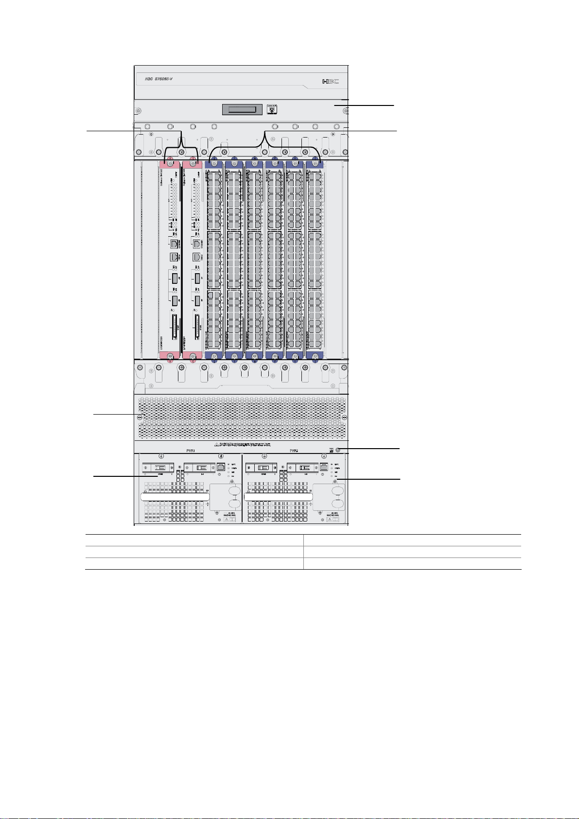
Figure 1-9 Front panel of the S7506E-V
(1)
(6)
(2)
(5)
(3)
(4)
(1) Fan tray (2) LPUs (in slot 2 to slot 7)
(3) Jack for ESD-preventive wrist strap (4) Power module
(5) Air filter (6) SRPUs (in slot 0 and slot 1)
All the modules of the switch are hot swappable.
z The S7506E-V switch has eight vertical slots. SRPUs are inserted in the left two slots (see callout 5
Figure 1-9). SRPUs are required and support active-standby switchover. Different LPUs are
in
inserted in the other six slots (see callout 2 in
z The fan tray is installed above the SRPUs and LPUs (see callout 1 in Figure 1-9) and the air flows
up from the bottom.
z The two power modules, which sit in the lower part of the chassis (see callout 4 in Figure 1-9),
provide 1+1 redundancy backup and support dual power supply inputs. You can select either AC
power supply or DC power supply.
Figure 1-9).
(4)
1-9
Page 17
Backplane
The backplane in the integrated chassis of the S7500E series implements high-speed data exchange
as well as management and control signal exchange between SRPUs and LPUs.
The backplane mainly provides the following functions:
z Interconnection between cards
z Card hot-swapping
z Automatic slot recognition
z Automatic chassis type recognition
z Distributed power supply to the system. The S7506E-V has two backplanes: signal backplane and
power supply backplane. The power supply backplane is connected to the power modules and is
also connected to the signal backplane with an internal cable.
z Connection of the signal cable that monitors the fan tray and power supply
Power Supply System
The S7500E series support a variety of power modules, as listed in Table 1-3.
Table 1-3 Power modules of the S7500E series
Model Height Power input mode Support PoE power
PSR320-A 1 U AC No
PSR320-D 1 U DC No
PSR650-A 1 U AC No
PSR650-D 1 U DC No
PSR1400-A 3 U AC No
PSR1400-D 3 U DC Yes
PSR2800-ACV 3 U AC Yes
PSR6000-ACV 3 U AC Yes
Table 1-4 Features of power modules
Feature Description
Support input under-voltage protection, output over-voltage
Protection functions
protection, short-circuit protection, over-current protection, and
overheat protection
1+1 hot backup support Support 1 + 1 hot backup and current sharing
Hot swap support
Support hot swap with the power switch turned off while the
device is in operation
Typically, the S7502E and the S7503E-S use 1U power modules, while the other models of the S7500E
series use 3U power modules.
The S7500E series support a large variety of card types, and system power consumption of a switch
varies with different types of cards in use. You can choose an appropriate power module model for your
switch based on its system power consumption.
1-10
Page 18
H3C has designed a power module adapter, PWR-SPA, to allow flexible power module options to suit
different system power consumption characteristics.
You can use PSR650 power modules in combination with PWR-SPA power module adapters to power a
switch with system power consumption lower than 650 W, instead of using heavy-duty power modules
like the PSR1400 or PSR2800.
The system power consumption of a switch is determined by its SRPUs, LPUs, and fan tray. Specifically,
the system power consumption of a switch is equal to the power consumption of its SRPUs, LPUs, and
fan tray put together.
For how to install power modules and power module adapters, refer to section 5.2 "Removing and
Installing a Power Module."
Table 1-5 Compatibility matrix between power modules and switch chassis
Chassis
(right)
Power
S7502E
S7503E-
S
S7503E
S7506E-
S
S7506E
S7506E-
V
S7510E
module
(below)
PSR320-A Y1 Y1 N N N N N
PSR320-D Y1 Y1 N N N N N
PSR650-A Y1 Y1 Y2 Y2 Y2 Y2 N
PSR650-D Y1 Y1 Y2 Y2 Y2 Y2 N
PSR1400-A N N Y1 Y1 Y1 Y1 Y1
PSR1400-D N N Y1 Y1 Y1 Y1 Y1
PSR2800-ACV N N Y1 Y1 Y1 Y1 Y1
PSR6000-ACV N N Y1 Y1 Y1 Y1 Y1
z Y1 means that the power module directly fits the chassis.
z Y2 means that you need to insert a power module adapter into the chassis and then inserting the
power module into the power module adapter.
z N means that the power module cannot be used in the chassis.
z Do not use different types of power modules in the same device.
1-11
Page 19
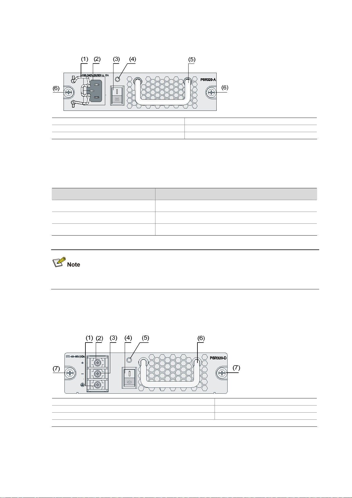
PSR320-A
Figure 1-10 PSR320-A power module
(1) Power cable retainer (2) AC power socket
(3) Power switch (4) Power LED
(5) Power module handle (6) Captive screws
As shown in the figure, above the power switch is the power LED. If the power LED is green, the power
supply operates normally. If the LED is red, the power supply is abnormal.
Table 1-6 Technical specifications of the PSR320-A power module
Item Specifications
Rated voltage range 100 VAC to 240 VAC; 50 Hz or 60 Hz
Maximum output power 300 W
Dimensions (H × W × D) 40 × 140 × 350 mm (1.57 × 5.51 × 13.78 in.)
The PSR320-A uses a 10-A AC power cable.
PSR320-D
Figure 1-11 PSR320-D power module
(1) Grounding screws (2) RTN terminal (+) of DC input
(3) Negative terminal (–) of DC input (–48 V to –60 V) (4) Power switch
(5) Power LED (6) Power module handle
(7) Captive screws
As shown in the figure, above the power switch is the power LED. If the power LED is green, the power
supply operates normally. If the power LED is red, the power supply is abnormal.
1-12
Page 20
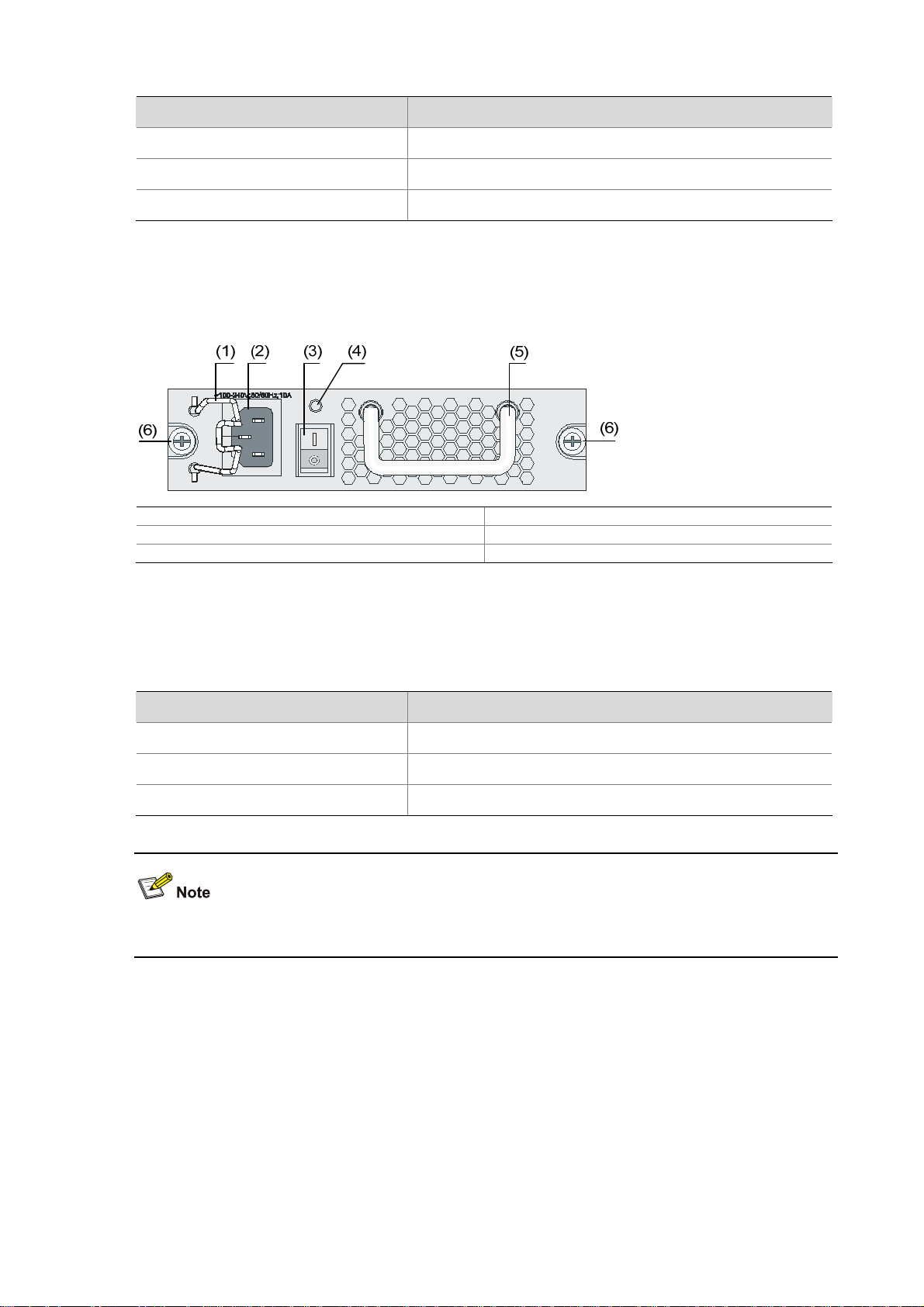
Table 1-7 Technical specifications of the PSR320-D power module
Item Specifications
Rated voltage range –48 VDC to –60 VDC
Maximum output power 300 W
Dimensions (H × W × D) 40 × 140 × 350 mm (1.57 × 5.51 × 13.78 in.)
PSR650-A
Figure 1-12 PSR650-A power module
(1) Power cable retainer (2) AC power socket
(3) Power switch (4) Power LED
(5) Power module handle (6) Captive screws
As shown in the figure, above the power switch is the power LED. If the power LED is green, the power
supply operates normally. If the LED is red, the power supply is abnormal.
Table 1-8 Technical specifications of the PSR650-A power module
Item Specifications
Rated voltage range 100 VAC to 240 VAC; 50 Hz or 60 Hz
Maximum output power 650 W
Dimensions (H × W × D) 40 × 140 × 350 mm (1.57 × 5.51 × 13.78 in.)
The PSR650-A uses a 10-A AC power cable.
1-13
Page 21
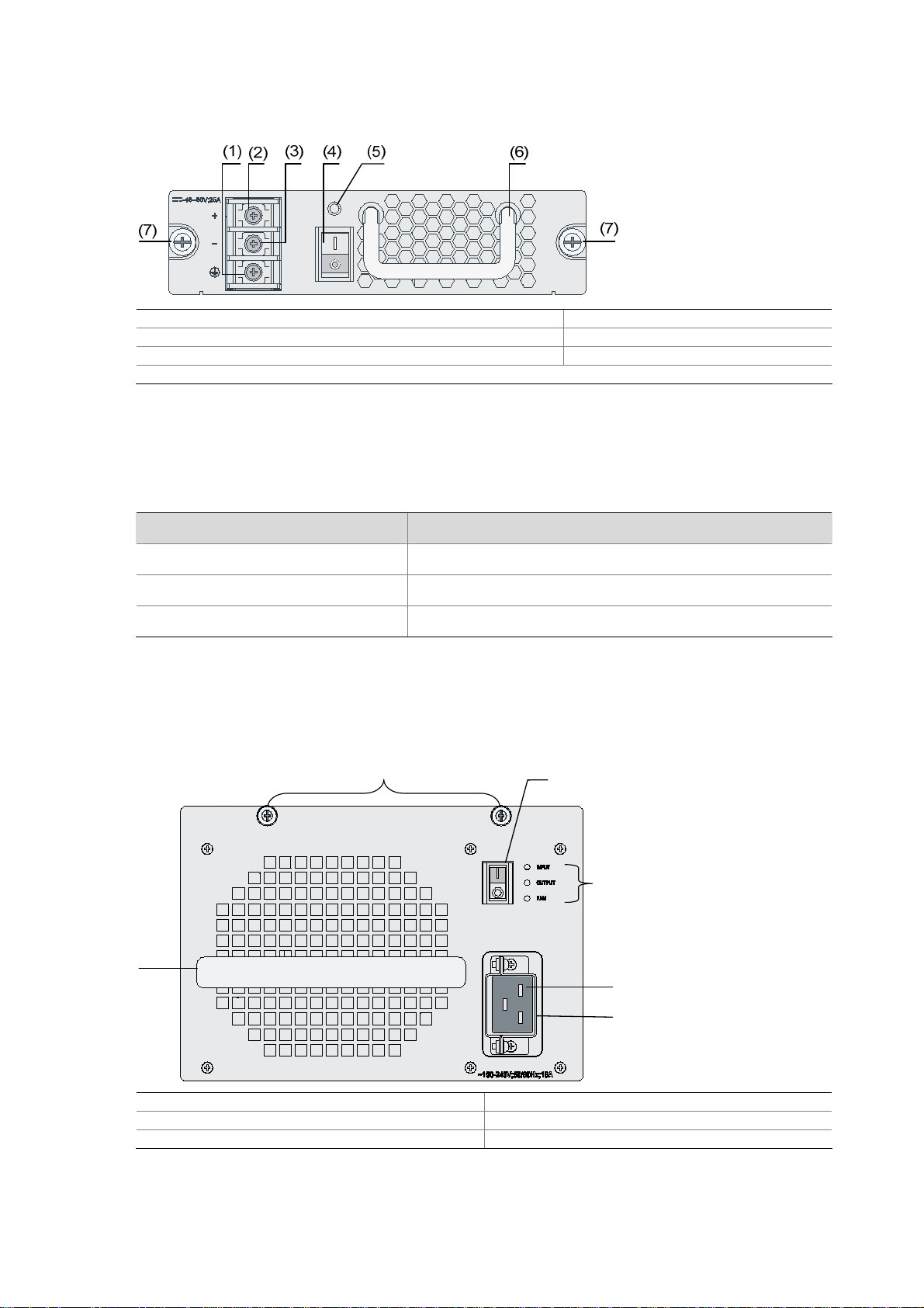
PSR650-D
Figure 1-13 PSR650-D power module
(1) Grounding screw (2) RTN terminal (+) of DC input
(3) Negative terminal (–) of DC input (–48 V to –60 V) (4) Power switch
(5) Power LED (6) Power module handle
(7) Captive screws
As shown in the figure, above the power switch is the power LED. If the power LED is green, the power
supply operates normally. If the power LED is red, the power supply is abnormal.
Table 1-9 Technical specifications of the PSR650-D power module
Item Specifications
Rated voltage range –48 VDC to –60 VDC
Maximum output power 650 W
Dimensions (H × W × D) 40 × 140 × 350 mm (1.57 × 5.51 × 13.78 in.)
PSR1400-A
Figure 1-14 PSR1400-A power module
(1)
(2)
(3)
(6)
(4)
(5)
(1) Captive screws (2) Power switch
(3) Power LEDs (4) AC power socket
(5) Power cable retainer (6) Power module handle
As shown in the figure, on the right of the power switch are the input LED, output LED, and fan LED. For
their colors and descriptions, refer to section 7.2.3 “Troubleshooting PSR1400-A.”
1-14
Page 22
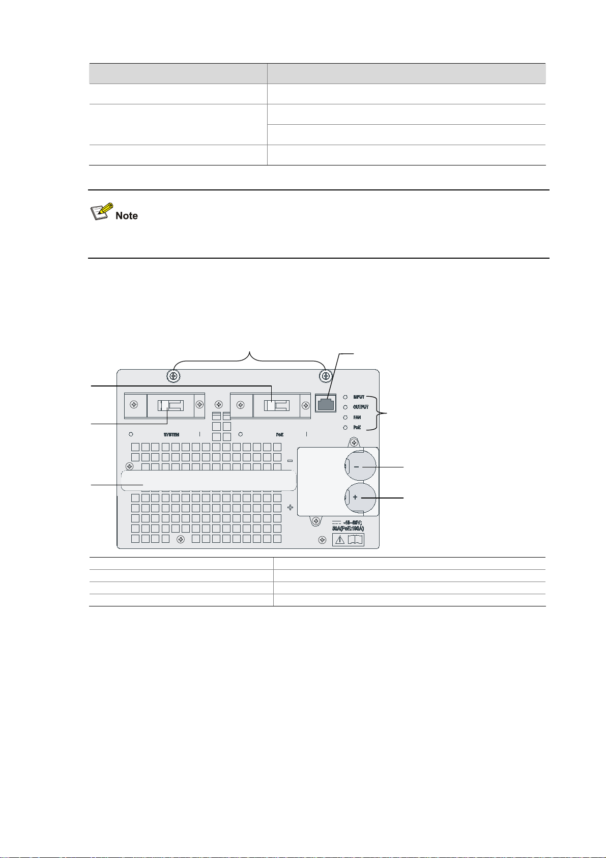
Table 1-10 Technical specifications of the PSR1400-A power module
Item Specifications
Rated voltage range 100 VAC to 240 VAC; 50 Hz or 60 Hz
Maximum output power
Dimensions (H × W × D) 128 × 196 × 380 mm (5.04 × 7.72 × 14.96 in.)
The PSR1400-A uses a 16-A AC power cable.
1150 W (110 V)
1400 W (220 V)
PSR1400-D
Figure 1-15 PSR1400-D power module
(1)
(2)
(8)
(7)
(3)
(4)
(6)
(5)
(1) Captive screws (2) COM port for monitoring PoE
(3) Power LEDs (4) Negative terminal (–) of DC input (–48 V to –60 V)
(5) RTN terminal (+) of DC input (6) Power module handle
(7) System power switch (8) PoE power switch
The PSR1400-D power module provides system power and PoE power. The switch marked “SYSTEM”
is used to control the system power, and the other marked “PoE” is used to control the PoE power. The
RJ-45 port (RS485) on the right of the PoE power switch is the COM port for monitoring PoE.
1-15
Page 23
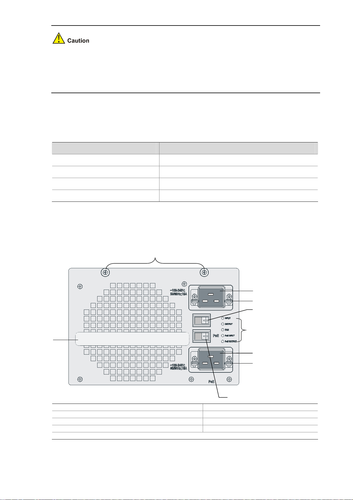
z If power to the PSR1400-D power module is switch controlled, make sure to disconnect the
negative input of the power module when disconnecting power to the power module.
z Keep the PoE switch in the off position unless the device is equipped with appropriate PoE-capable
cards and needs to offer PoE supply.
As shown in the figure, on the right of the panel are the input LED, output LED, fan LED and PoE LED.
For their colors and descriptions, refer to section 7.2.4 “Troubleshooting PSR1400-D.”
Table 1-11 Technical specifications of the PSR1400-D DC power module
Item Specifications
Rated voltage range –48 VDC to –60 VDC
Maximum system output power 1400 W
Maximum PoE output power 6720 W (–48 V)
Dimensions (H × W × D) 128 × 196 × 380 mm (5.04 × 7.72 × 14.96 in.)
PSR2800-ACV
Figure 1-16 PSR2800-ACV power module
(1)
(2)
(3)
(4)
(9)
(5)
(6)
(7)
(8)
(1) Captive screws (2) System power socket
(3) Power cable retainer (4) System power switch
(5) Power LEDs (6) PoE power socket
(7) Power cable retainer (8) PoE power switch
(9) Power module handle
The PSR2800-ACV power module provides system power and PoE power. In
indicated by callout 4 is used to control the system power and the socket indicated by callout 2 is used
1-16
Figure 1-16, the switch
Page 24
for system power input, while the switch indicated by callout 8 is used to control the PoE power and the
socket indicated by callout 6 is used for PoE power input.
Keep the PoE switch in the off position unless the device is equipped with appropriate PoE-capable
cards and needs to offer PoE supply.
On the right of the panel are the input LED, output LED, fan LED, PoE input LED, and PoE output LED.
For the descriptions of these LEDs, refer to section 7.2.5 “Troubleshooting PSR2800-ACV.”
Table 1-12 Technical specifications of the PSR2800-ACV power module
Item Specifications
Rated voltage range 100 VAC to 240 VAC, 50 Hz or 60 Hz
Maximum system output power
Maximum PoE output power
Dimensions (H × W × D) 128 × 196 × 380 mm (5.04 × 7.72 × 14.96 in.)
1150 W (110 V)
1400 W (220 V)
1150 W (110 V)
1400 W (220 V)
PSR6000-ACV
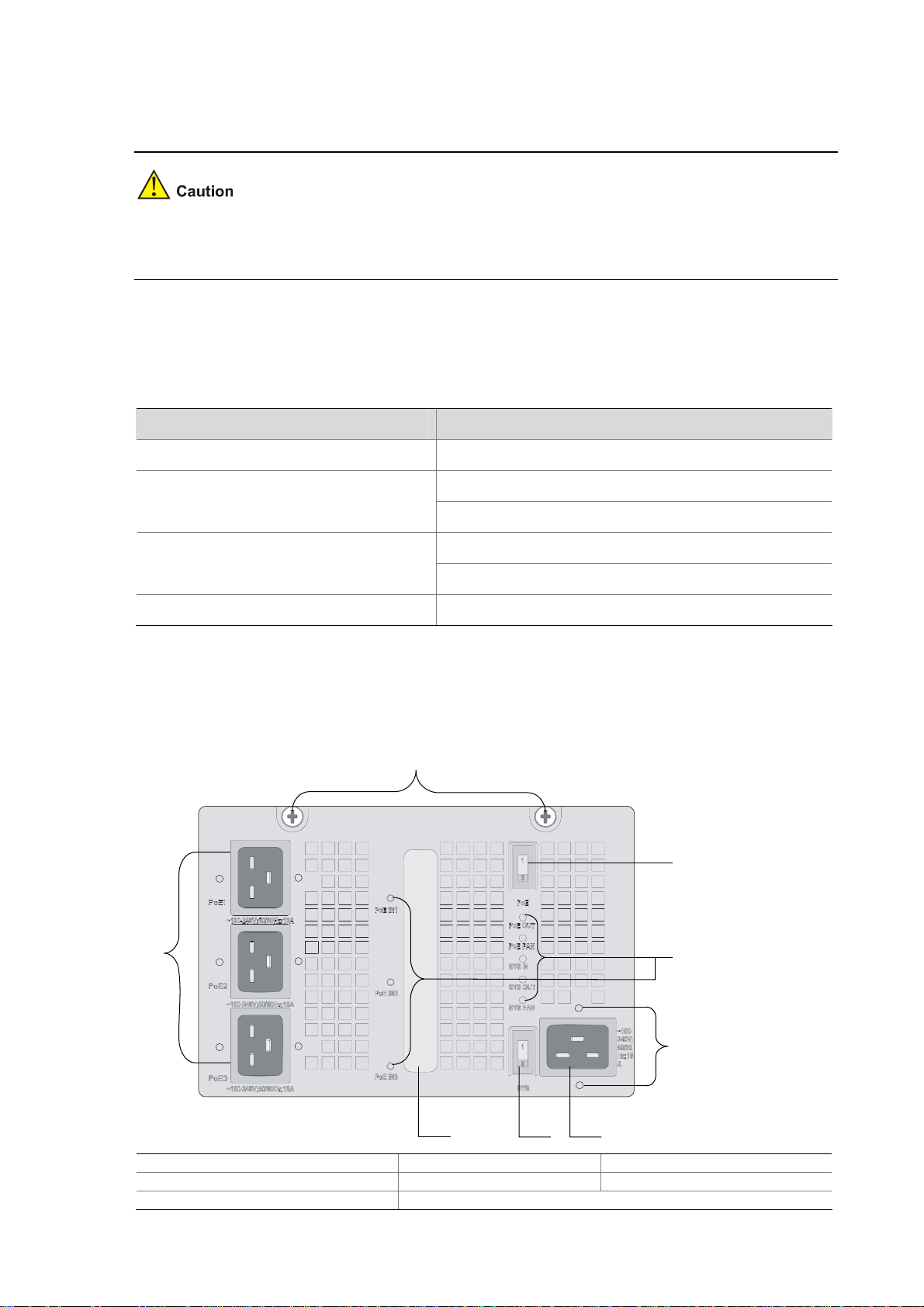
Figure 1-17 PSR6000-ACV power module
(1)
(2)
(8)
(3)
(4)
(6)(7)
(1) Captive screws (2) PoE power switch (3) Power LEDs
(4) Power cable retainer screws (5) System power socket (6) System power switch
(7) Power module handle (8) PoE power sockets
1-17
(5)
Page 25
The PSR6000-ACV power module provides system power and PoE power. In Figure 1-17 the switch
indicated by callout 6 is used to control the system power and the socket indicated by callout 5 is used
for system power input, while the switch indicated by callout 2 is used to control the PoE power and the
sockets indicated by callout 8 are used for PoE power inputs.
To provide PoE power by the PSR6000-ACV, you need to
z Switch on the system power and make sure that the system power output is normal
z Switch on the PoE power and make sure that one of the three PoE power inputs is alive
The PoE output power of the PSR6000-ACV depends on the number of PoE power inputs that are
selected as needed. For detailed technical specifications, refer to
Table 1-13.
z If the system power input and multiple PoE power inputs are used at the same time, the input
voltage must be the same, that is, either 110 VAC or 220 VAC, but not be intermixed.
z Keep the PoE switch in the off position unless the device is equipped with appropriate PoE-capable
cards and needs to offer PoE supply.
On the right of the panel are the system power input LED (SYS IN), system power output LED (SYS
OUT), system power fan LED (SYS FAN), PoE input LEDs (PoE IN1, PoE IN2, and PoE IN3), PoE
output LED (PoE OUT), and PoE power fan LED (PoE FAN). For the descriptions of these LEDs, refer
to section 7.2.6 “Troubleshooting PSR6000-ACV.”
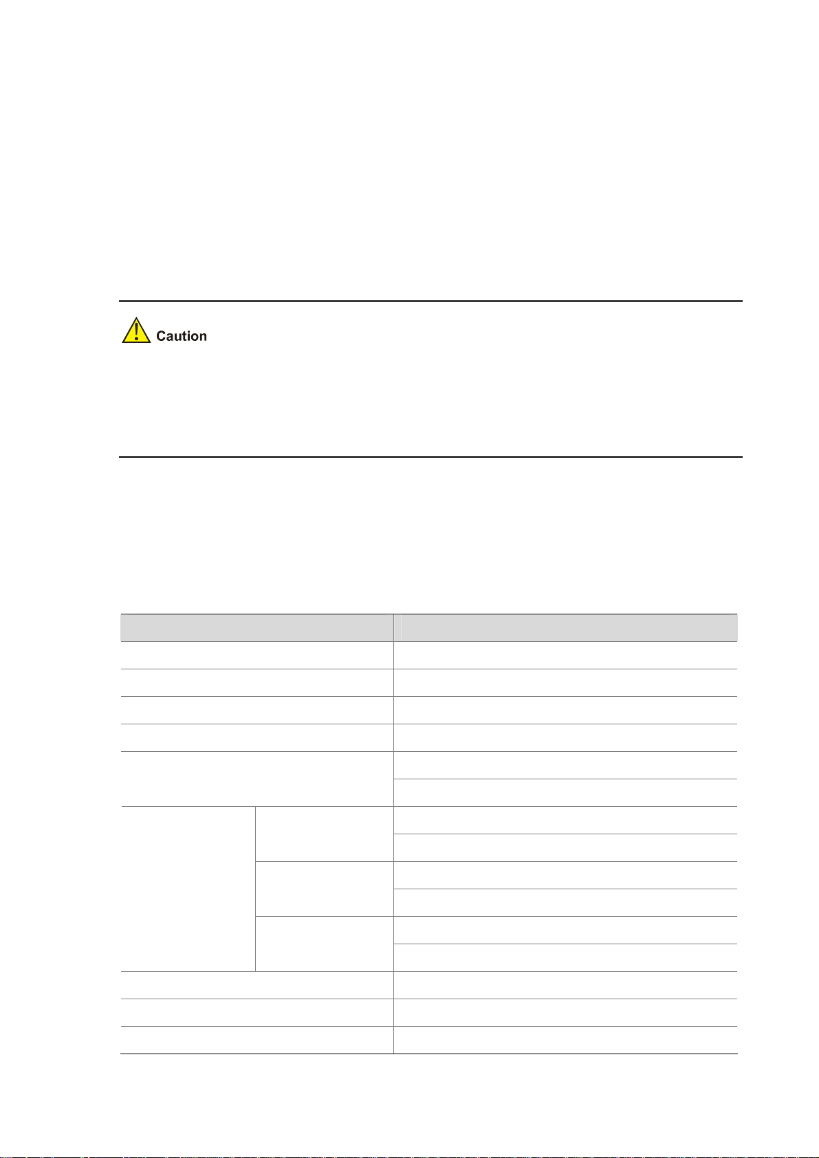
Table 1-13 Technical specifications of the PSR6000-ACV power module
Item Specifications
Rated voltage range 100 VAC to 240 VAC, 50 Hz or 60 Hz
Maximum input current for each socket 16 A
Maximum system output current 117 A
Maximum PoE output current 100 A
1150 W (110 VAC)
Maximum system output power
1400 W (220 VAC)
1200 W (110 VAC)
One PoE input
1800 W (220 VAC)
Maximum PoE
output power
Two PoE inputs
2400 W (110 VAC)
3600 W (220 VAC)
3600 W (110 VAC)
Three PoE inputs
5300 W (220 VAC)
Dimensions (H × W × D) 128 × 196 × 380 mm (5.04 × 7.72 × 14.96 in.)
Operating temperature 0°C to 45°C (32°F to 113°F)
Storage temperature –40°C to +70°C (–40°F to +158°F)
1-18
Page 26
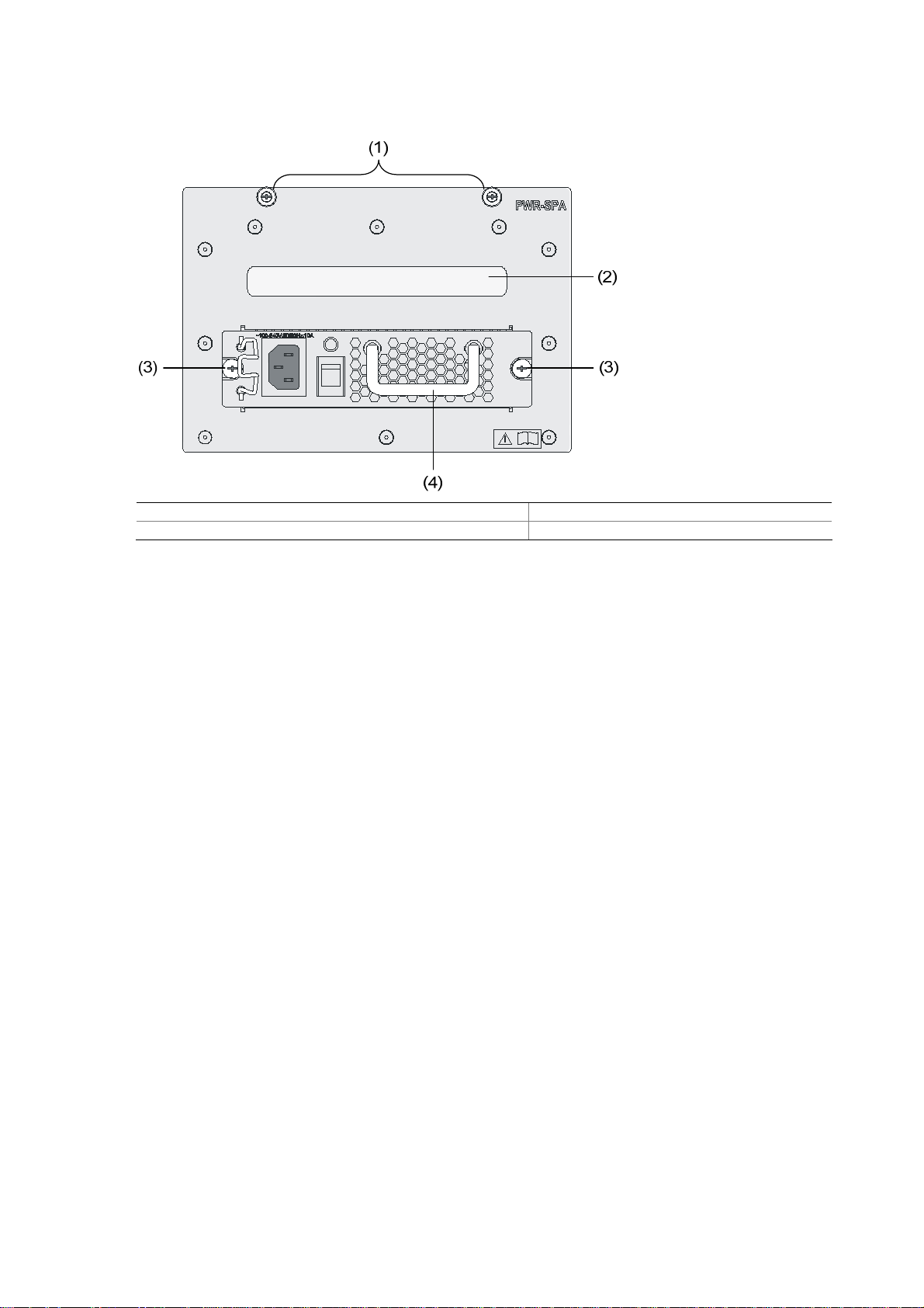
PWR-SPA
Figure 1-18 Schematic view of the power module adapter with a PSR650-A installed
(1) Captive screws on the power module adapter (2) Power module adapter handle
(3) Captive screw on the PWR-SPA power module (4) PWR-SPA power module handle
When the system power consumption of a switch (S7503E, S7506E, S7506E-V, or S7510E) is less than
the maximum output power of a 1U power module, you can first insert the PWR-SPA power module
adapters into the switch, and then insert 1U power modules into the power module adapters. By doing
so, you can use the 1U power modules to power the switch.
A PWR-SPA power module adapter has the same physical dimensions with a 3U power module.
Fan Tray
The S7502E, S7503E-S, S7503E, S7506E-S, S7506E and S7510E switches provide chassis for
horizontal cards. The fan tray is installed on the right side of the front of the chassis. The S7506E-V
switch provides chassis for vertical cards. The fan tray is installed on the upper of the front of the
chassis.
1-19
Page 27
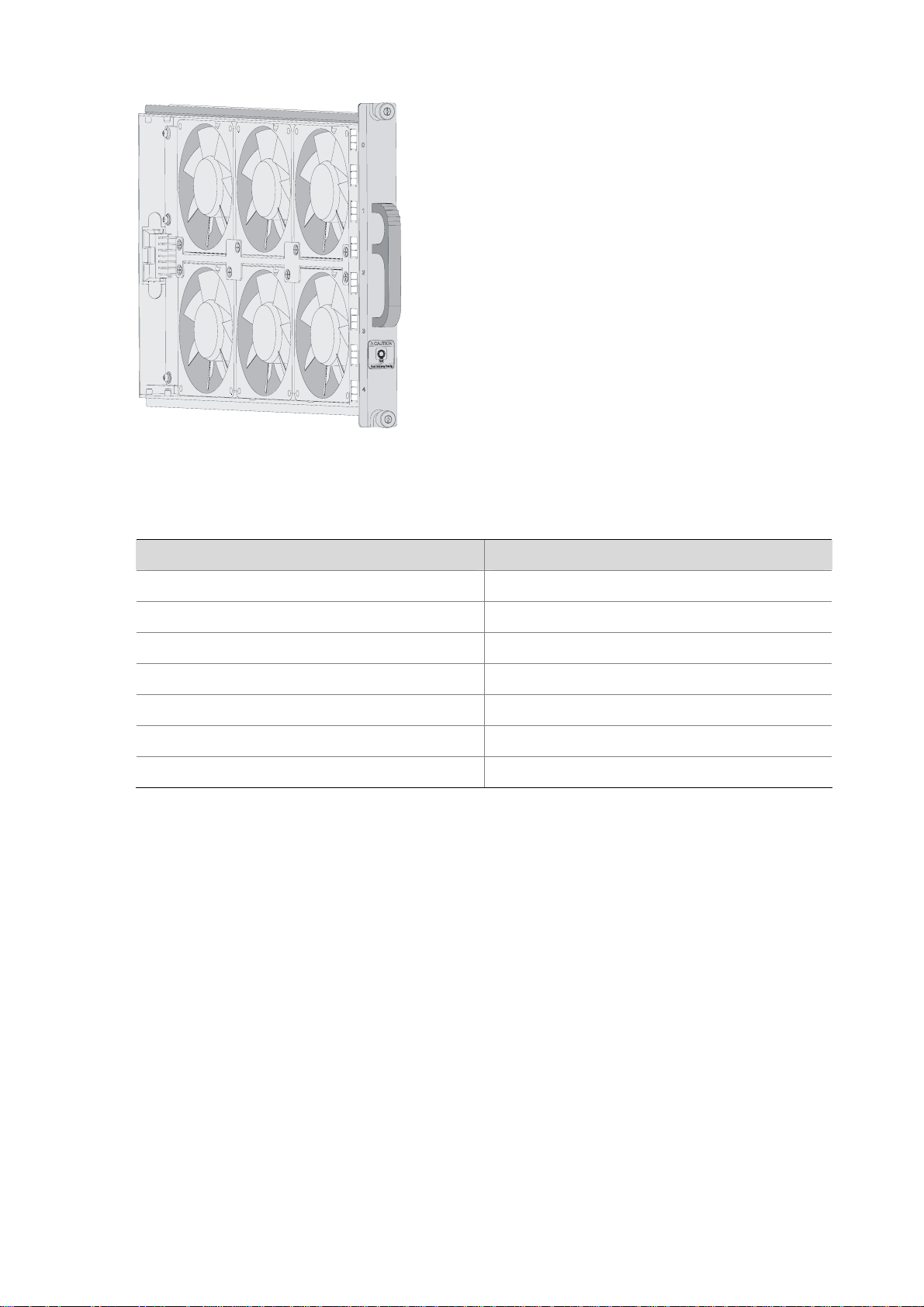
Figure 1-19 Fan tray (for the S7503E)
The power consumption of the fan trays for the S7500E series varies with fan tray models.
Table 1-14 Power consumption of the fan trays for the S7500E series
S7502E fan tray 20
S7503E-S fan tray 20
S7503E fan tray 30
S7506E-S fan tray 45
S7506E fan tray 45
S7510E fan tray 50
S7506E-V fan tray 50
Air Filter
Over a long period of time, dust may block the air filter at the air intake vent of the S7500E series. As a
result, the heat dissipation of the system may be affected. You are recommended to clean the air filter
every three months. Air filters are optional accessories.
Since the air flows up from the bottom, air filters for the S7506E-V, different from those for the other
models, are installed on the front and rear sides near the bottom of the chassis.
Model Power consumption (W)
SRPUs
SRPU Types
For the S7500E series, SRPUs are the core in the control and management plane and switching fabric.
The S7500E series provide 10 types of SRPUs.
1-20
Page 28
Table 1-15 SRPUs and their suitable chassis
Chassis (right)
Engine (below)
LSQ1MPUA0 Yes No No No No No No
LSQ1CGP24TSC0 No Yes No No No No No
LSQ1CGV24PSC0 No Yes No No No No No
LSQ1SRP2XB0
(Salience VI-10GE)
LSQ1SRPA0
(Salience
VI-Smart)
LSQ1SRPB0
(Salience VI)
LSQ1SRP1CB0
(Salience VI-Turbo)
LSQ1MPUB0
(Salience VI-Lite)
LSQ1SRPD0
(Salience VI-Plus)
S7502E
No No Yes No Yes Yes Yes
No No No Yes No No No
No No Yes No Yes Yes Yes
No No Yes No Yes Yes Yes
No No Yes No Yes Yes Yes
No No Yes No Yes Yes Yes
S7503E-
S
S7503E
S7506E-
S
S7506E S7510E
S7506E-
V
LSQ1SRP12GB0
(Salience VI-GE)
The S7500E series, except the S7503E-S, are a dual-SRPU system. The SRPUs in a chassis must be
of the same type.
LSQ1MPUA0 SRPU
Applicable model
S7502E
Technical specifications
Table 1-16 Technical specifications of the LSQ1MPUA0
Item Specifications
No No Yes No Yes Yes Yes
CPU MIPS64, 600 MHz
Boot ROM 512 KB
Flash memory 64 MB
DDR SDRAM 512 MB
Dimensions (H × W × D) 45 × 199 × 355 mm (1.77 × 7.83 × 13.98 in.)
1-21
Page 29
Interfaces
Power consumption 10 W to 15 W
The dimensions of the S7500E series are expressed in the form of H × W × D, where
z H: Height of the front panel of the card.
z W: Width of the part inserted into the chassis, instead of that of the front panel.
z D: Depth from the front panel to the other end, excluding the length of the handle.
Panel and LEDs
Item Specifications
z One compact flash (CF) card slot
z One console port, used for local or remote configuration and
management of the switch through a dialup configuration
z One 10/100Base-TX management port
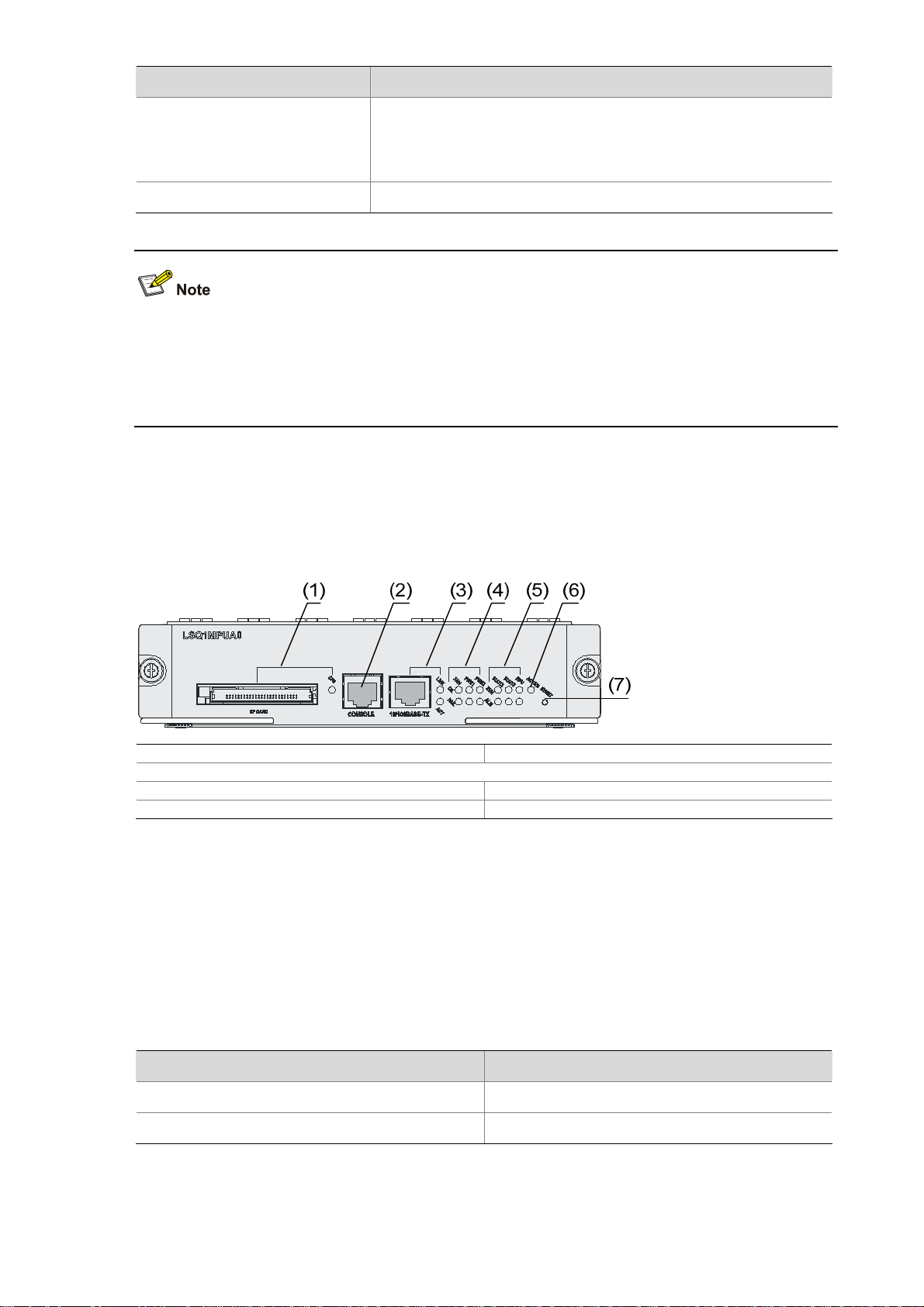
Figure 1-20 shows the front panel of the LSQ1MPUA0.
Figure 1-20 Front panel of the LSQ1MPUA0
(1) CF card slot and CFS LED (2) Console port
(3) 10/100Base-TX management port and its LEDs
(4) Power and fan tray status LEDs (5) LPU status LEDs
(6) ACTIVE LED of LSQ1MPUA0 (7) RESET button
On-board interfaces
z CF card slot
The CF card slot can accommodate a standard CF card (Type I or Type II), where you can store host
software and logs, and thus upgrade software conveniently. The CF card is hot swappable.
Table 1-17 describes the CFS LED on the right of the CF card.
Table 1-17 Description of the CFS LED
Status Description
OFF No CF card is in position.
ON The CF card is in position.
z Console port
1-22
Page 30
Using an RJ-45 connector, the console port can be connected through a common asynchronous serial
cable directly to a computer for system debugging, configuration, maintenance, management, and host
software loading, or to a modem for remote system debugging, configuration, maintenance and
management.
Table 1-18 Specifications of the console port
Item Specifications
Connector type RJ-45
Number of connectors 1
Interface standard Asynchronous EIA/TIA-232
Baud rate 115200 bps (9600 bps by default)
Transmission distance 15 m (49.21 ft.)
z It can be connected to an ASCII terminal.
Functions
z It can be connected to a serial port of a local or remote
(through a pair of modems) PC running terminal emulation
program.
z 10/100Base-TX management port
Using an RJ-45 connector, the 10/100Base-TX management port can be connected to a local PC for
switch program loading and switch debugging, or connected to a remote NMS for remote management.
Table 1-19 Specifications of the 10/100Base-TX management port
Item Specifications
Connector type RJ-45
Number of connectors 1
Transmission speed and type 10/100 Mbps, half/full duplex
Cable medium and maximum transmission
distance
Function
Category-5 twisted pair, with a maximum
transmission distance of 100 m (328.08 ft.)
Host software and Boot ROM upgrade and network
management
Table 1-20 describes the LED status of the 10/100Base-TX management port.
Table 1-20 Description of the status LEDs of the 10/100Base-TX management port
LED Description
LINK
ACT
System LEDs
z System status LEDs
z OFF: No link is present.
z ON: A link is present.
z OFF: No data is being transmitted or received.
z Blinking: Data is being transmitted or received.
1-23
Page 31

The LEDs on the card panel indicate the statuses of the power modules, fan tray, two LPUs, and
LSQ1MPUA0 itself.
z Power status LEDs
PWR1 and PWR2: The LEDs show the status of the two power modules (AC or DC).
Table 1-21 Description of the power status LEDs
LED Description
OK
FAIL
z ON: The power module works normally.
z OFF: The power module is faulty or out of position.
z ON: The power module is faulty, or there is no power input to the power
module, or the power switch is turned off.
z OFF: The power module is operational or out of position.
z Fan status LEDs
FAN: The LEDs show the status of the fan tray.
Table 1-22 Description of the fan status LEDs
LED Description
OK
FAIL
z ON: The fans operate normally.
z OFF: The fans are faulty or out of position.
z ON: The fans are faulty or out of position.
z OFF: The fans operate normally.
z LPU status LEDs (SLOT2, SLOT3, MPU)
SLOT2 and SLOT3: The LEDs show the status of the LPUs in slot 2 and slot 3.
MPU: The LEDs show the status of the LSQ1MPUA0 itself.
Table 1-23 Description of LPU status LEDs
LED Description
RUN
ALM
z ON/OFF: The LPU is faulty or out of position.
z Blinking: The LPU is operating normally.
z OFF: The LPU is operational or out of position.
z ON: The LPU is faulty.
If the RUN LED flashes at a high frequency, the card is in the startup process, but is not yet operational.
At system startup, the ALM LED will be ON for a while but it does not mean that the card is faulty.
z ACTIVE LED
The ACTIVE LED shows the active/standby status of the LSQ1MPUA0. If the ACTIVE LED is ON, the
LSQ1MPUA0 is active; if OFF, the LSQ1MPUA0 is standby.
1-24
Page 32

RESET button
A reset button is provided on the LSQ1MPUA0 for you to reset the card when necessary.
Dedicated S7503E-S SRPU-LSQ1CGP24TSC0
Applicable model
S7503E-S
Technical specifications
Table 1-24 Technical specifications of the LSQ1CGP24TSC0
Item Specifications
CPU MIPS64, 400 MHz
Boot ROM 512 KB
Flash memory 64 MB
DDR SDRAM 512 MB
Dimensions (H × W × D) 45 × 377 × 355 mm (1.77 × 14.84 × 13.98 in.)
z One console port, used for local or remote configuration and
management of the switch through a dialup connection
z One 10/100Base-TX management port
z Sixteen 1000Base-X-SFP/100Base-FX-SFP ports
Ports
z Eight Combo ports, each of which consists of a
10/100/1000Base-T port and an SFP port. The two ports
comprising a Combo port cannot operate at the same time.
For the pairings of the SFP ports and 10/100/1000Base-T
ports, refer to
Table 1-26.
Power consumption 25 W to 45 W
Panel and LEDs
Figure 1-21 shows the front panel of the LSQ1CGP24TSC0.
Figure 1-21 Front panel of the LSQ1CGP24TSC0
(1)
(2)
(3)
(4)
(5)
(6)
(7)
(1) 1000Base-X-SFP/100Base-FX-SFP ports (2) Combo ports
(3) Console port
(4) 10/100Base-TX management port and its LEDs
(5) Power and fan tray status LEDs (6) LPU status LEDs
(7) RESET button
On-board interfaces
z SFP ports and Combo ports
1-25
Page 33

The LSQ1CGP24TSC0 provides sixteen 1000Base-X-SFP/100Base-FX-SFP ports and eight Combo
ports.
Table 1-25 Specifications of the Ethernet ports
Item Specifications
Connector types
Number of connectors
Pluggable module type
z LC
z RJ-45
z 16 SFP connectors
z 8 Combo connectors
z Gigabit SFP modules
z 100 Mbps SFP modules
For details, refer to “Appendix A List of Pluggable Optical Modules.”
Table 1-26 shows the pairings of the eight SFP ports and the eight 10/100/1000Base-T ports for the
Combo ports.
Table 1-26 Pairings of the SFP ports and the 10/100/1000Base-T ports for the Combo ports
1000Base-X-SFP/100Base-FX-SFP port
number
10/100/1000Base-T port number
17 25
18 26
19 27
20 28
21 29
22 30
23 31
24 32
z In a Combo port, only one of the 1000Base-X-SFP/100Base-FX-SFP port and the
10/100/1000Base-T port can be used at a time.
z The 1000Base-X-SFP/100Base-FX-SFP port of a Combo port does not support the pluggable
SFP-GE-T module.
Each Ethernet port has a green LED.
Table 1-27 describes the LED.
Table 1-27 Description of the LED of each Ethernet port
Status Meaning
OFF No link is present.
ON A link is present.
1-26
Page 34

Status Meaning
Blinking Data is being transmitted or received.
z Console port
Using an RJ-45 connector, the console port can be connected through a common asynchronous serial
cable directly to a computer for system debugging, configuration, maintenance, management, and host
software loading, or to a modem for remote system debugging, configuration, maintenance and
management.
Table 1-28 Specifications of the console port
Item Specifications
Connector type RJ-45
Number of connectors 1
Interface standard Asynchronous EIA/TIA-232
Baud rate 115200 bps (9600 bps by default)
Transmission distance 15 m (49.21 ft.)
z It can be connected to an ASCII terminal.
Functions
z It can be connected to the serial port of a local or
remote (through a pair of modems) PC running terminal
emulation program.
z 10/100Base-TX management port
Using an RJ-45 connector, the interface can be connected through a common asynchronous serial
cable directly to a computer for switch program loading and switch debugging, or to a remote NMS for
remote management.
Table 1-29 Specifications of the 10/100Base-TX management port
Item Specifications
Connector type RJ-45
Number of connectors 1
Transmission speed and type 10/100 Mbps, half/full duplex
Cable medium and maximum transmission
distance
Category-5 twisted pair, with a maximum
transmission distance of 100 m (328.08 ft.)
Function
Used for switch software upgrade and network
management
Table 1-30 describes the status LEDs of the 10/100Base-TX management port.
1-27
Page 35

Table 1-30 Description of the status LEDs of the 10/100Base-TX management port
LED Description
LINK
ACT
z OFF: No link is present.
z ON: A link is present.
z OFF: No data is being transmitted or received.
z Blinking: Data is being transmitted or received.
System LEDs
z System status LEDs
The LEDs on the card panel indicate the statuses of the power modules, fan tray, LPUs, and
LSQ1CGP24TSC0 itself.
z Power status LEDs
PWR: The power status LEDs show the status of the power modules.
Table 1-31 Description of the power status LEDs
LED Description
OK
FAIL
z ON: The power modules operate normally.
z OFF: The power module is faulty or out of position.
z ON: At least one power module is faulty or switched off.
z OFF: The power modules are operational or out of position.
z Fan status LEDs
FAN: The LEDs shows the status of the fan tray.
Table 1-32 Description of the fan status LEDs
LED Description
OK
FAIL
z ON: The fans operate normally.
z OFF: The fans are faulty or out of position.
z ON: The fans are faulty or out of position.
z OFF: The fans operate normally.
z LPU status LEDs (SLOT0, SLOT1, and SLOT2)
SLOT0, SLOT1, and SLOT2: The LPU status LEDs indicate the status of the LPUs seated in these
three slots.
Table 1-33 Description of LPU status LEDs
LED Description
RUN
ALM
z ON/OFF: The LPU is faulty or out of position.
z Blinking: The LPU is operating normally.
z OFF: The LPU is operational or out of position.
z ON: The LPU is faulty.
1-28
Page 36

If the RUN LED flashes at a high frequency, the card is in the startup process, but is not operational yet.
At system startup, the ALM LED will be ON for a while, but it does not mean that the card is faulty.
RESET button
A reset button is provided on the LSQ1CGP24TSC0 for you to reset the card when necessary.
Dedicated S7503E-S SRPU-LSQ1CGV24PSC0
Applicable model
S7503E-S
Technical specifications
Table 1-34 Technical specifications of the LSQ1CGV24PSC0
Item Specifications
CPU MIPS64, 400 MHz
Boot ROM 4 MB
Flash memory 64 MB
DDR SDRAM 512 MB
Dimensions (H × W × D) 45 × 377 × 355 mm (1.77 × 14.84 × 13.98 in.)
z One console port, used for local or remote configuration and
management of the switch through a dialup connection
z One 10/100Base-TX management port
z Twenty 10/100/1000Base-T ports
Ports
z Four Combo ports, each of which consists of a
10/100/1000Base-T port and an SFP port. The two ports
comprising a Combo port cannot operate at the same time. For
the pairings of the SFP ports and the 10/100/1000Base-T ports,
refer to
Table 1-36.
Power consumption 30 W to 60 W
Panel and LEDs
Figure 1-22 shows the front panel of the LSQ1CGV24PSC0.
1-29
Page 37

Figure 1-22 Front panel of the LSQ1CGV24PSC0
(1) Combo ports (2) 10/100/1000Base-T ports
(3) Console port (4) 10/100Base-TX management port and its LEDs
(5) Power and fan tray status LEDs (6) LPU status LEDs
(7) RESET button
On-board interfaces
z 10/100/1000Base-T ports and Combo ports
The LSQ1CGV24PSC0 provides twenty 10/100/1000Base-T ports and four Combo ports and can be
upgraded to support the PoE function.
Table 1-35 Specifications of the Ethernet ports
Item Specifications
Connector types
Number of connectors
Pluggable module type
z LC
z RJ-45
z 20 RJ-45 connectors
z 4 Combo connectors
z Gigabit SFP modules
z 100 Mbps SFP modules
For details, refer to “Appendix A List of Pluggable Optical Modules.”
The LSQ1CGV24PSC0 provides two expansion slots (SLOT0 and SLOT1) for installing subcards. After
a subcard is inserted into one of the slots, the 10/100/1000Base-T ports numbered 25 through 28
cannot be used. For the installation procedure and specifications, refer to the corresponding subcard
manuals.
Table 1-36 shows the pairings of the SFP ports and the 10/100/1000Base-T ports for the Combo ports.
Table 1-36 Pairings of the SFP ports and the 10/100/1000Base-T ports for the Combo ports
1000Base-X-SFP/100Base-FX-SFP port
number
10/100/1000Base-T port number
1 5
2 6
3 7
4 8
1-30
Page 38

z In a Combo port, only one of the 1000Base-X-SFP/100Base-FX-SFP port and the
10/100/1000Base-T port can be used at a time.
z The 1000Base-X-SFP/100Base-FX-SFP port of a Combo port does not support the pluggable
SFP-GE-T module.
Each Ethernet port has a LED.
Table 1-37 describes the LEDs when no subcard is installed.
Table 1-37 Description of the LED of each Ethernet port with no subcard installed
Color Status Meaning
ON No link is present.
Green
OFF A link is present.
Blinking Data is being transmitted or received.
Table 1-38 describes the LEDs for ports numbered 25 through 28 when one or more subcards are
installed.
Table 1-38 Description of LEDs for ports 25 through 28 with subcards installed
Color Status Meaning
ON
Yellow
Blinking
z The subcard is being installed.
z The port is invalid.
z The subcard is operating normally.
z The port is invalid.
LEDs of ports numbered 25 and 26 indicate subcard 0; LEDs of ports numbered 27 and 28 indicate
subcard 1. For example, after subcard 0 is installed, the four LEDs are steady yellow. When the subcard
operates normally, LEDs of ports numbered 25 and 26 become blinking yellow, while LEDs of ports
numbered 27 and 28 are still steady yellow. The status of the LEDs indicates that subcard 0 is operating
normally, subcard 1 is unavailable, and Ethernet ports numbered 25 through 28 are invalid.
z Console port
Using an RJ-45 connector, the console port can be connected through a common asynchronous serial
cable directly to a computer for system debugging, configuration, maintenance, management, and host
software loading, or to a modem for remote system debugging, configuration, maintenance and
management.
Table 1-39 Specifications of the console port
Item Specifications
Connector type RJ-45
Number of connectors 1
Interface standard Asynchronous EIA/TIA-232
Baud rate 115200 bps (9600 bps by default)
1-31
Page 39

Item Specifications
Transmission distance 15 m (49.21 ft.)
z It can be connected to an ASCII terminal.
Functions
z It can be connected to the serial port of a local or
remote (through a pair of modems) PC running terminal
emulation program.
z 10/100Base-TX management port
Using an RJ-45 connector, the interface can be connected through a common asynchronous serial
cable directly to a computer for switch program loading and switch debugging, or to a remote NMS for
remote management.
Table 1-40 Specifications of the 10/100Base-TX management port
Item Specifications
Connector type RJ-45
Number of connectors 1
Transmission speed and type 10/100 Mbps, half/full duplex
Cable medium and maximum
transmission distance
Category-5 twisted pair, with a maximum transmission distance of
100 m (328.08 ft.)
Function Used for switch software upgrade and network management
Table 1-41 describes the status LEDs of the 10/100Base-TX management port.
Table 1-41 Description of the status LEDs of the 10/100Base-TX management port
LED Description
LINK
ACT
z OFF: No link is present.
z ON: A link is present.
z OFF: No data is being transmitted or received.
z Blinking: Data is being transmitted or received.
System LEDs
z System status LEDs
The LEDs on the card panel indicate the statuses of the power modules, fan tray, LPUs, and
LSQ1CGV24PSC0 itself.
z Power status LEDs
PWR: The power status LEDs show the status of the power modules.
Table 1-42 Description of the power status LEDs
LED Description
OK
FAIL
z ON: The power modules operate normally.
z OFF: The power module is faulty or out of position.
z ON: At least one power module is faulty or switched off.
z OFF: The power modules are operational or out of position.
1-32
Page 40

z Fan status LEDs
FAN: The LEDs shows the status of the fan tray.
Table 1-43 Description of the fan status LEDs
LED Description
OK
FAIL
z ON: The fans operate normally.
z OFF: The fans are faulty or out of position.
z ON: The fans are faulty or out of position.
z OFF: The fans operate normally.
z LPU status LEDs (SLOT0, SLOT1, and SLOT2)
SLOT0, SLOT1, and SLOT2: The LPU status LEDs indicate the status of the LPUs seated in these
three slots.
Table 1-44 Description of LPU status LEDs
LED Description
RUN
ALM
z ON/OFF: The LPU is faulty or out of position.
z Blinking: The LPU is operating normally.
z OFF: The LPU is operational or out of position.
z ON: The LPU is faulty.
If the RUN LED flashes at a high frequency, the card is in the startup process, but is not operational yet.
At system startup, the ALM LED will be ON for a while, but it does not mean that the card is faulty.
RESET button
A reset button is provided on the LSQ1CGV24PSC0 for you to reset the card when necessary.
Salience VI-10GE SRPU-LSQ1SRP2XB0
Applicable models
z S7503E
z S7506E
z S7510E
z S7506E-V
Technical specifications
Table 1-45 Technical specifications of the LSQ1SRP2XB0
Item Specifications
CPU MIPS64, 600 MHz
Boot ROM 512 KB
1-33
Page 41

Flash memory 64 MB
DDR SDRAM 512 MB
Dimensions (H × W × D) 45 × 377 × 355 mm (1.77 × 14.84 × 13.98 in.)
Interfaces
Power consumption 55 W to 65 W
Panel and LEDs
Figure 1-23 shows the front panel of the LSQ1SRP2XB0.
Figure 1-23 Front panel of the LSQ1SRP2XB0
Item Specifications
z One CF card slot
z Two 10GBase-R-XFP ports
z One console port, used for local or remote configuration and
management of the switch through a dialup connection
z One 10/100Base-TX management port
(1) CF card slot and CFS LED (2) 10GBase-R-XFP ports and LEDs
(3) Console port (4) 10/100Base-TX management port and its LEDs
(5) Power and fan tray status LEDs (6) LPU status LEDs
(7) ACTIVE LED of LSQ1SRP2XB0 (8) RESET button
On-board interfaces
z CF card slot
The CF card slot can accommodate a standard CF card (Type I or Type II), where you can store host
software and logs, and thus upgrade software conveniently. The CF card is hot swappable.
Table 1-46 describes the CFS LED on the right of the CF card.
Table 1-46 Description of the CFS LED
Status Description
OFF No CF card is in position.
ON The CF card is in position.
z 10GBase-R-XFP ports
Table 1-47 Specifications of the 10GBase-R-XFP ports
Item Specifications
Connector type LC
Number of connectors 2
1-34
Page 42

Item Specifications
Interface standard 10GBase-R
Applicable fiber module For details, refer to “Appendix A List of Pluggable Optional Modules.”
Table 1-48 describes the status LEDs of 10GBase-R-XFP ports.
Table 1-48 Description of the status LEDs of 10GBase-R-XFP ports
LED Description
LINK
ACT
z OFF: No link is present.
z ON: A link is present.
z OFF: No data is being transmitted or received.
z Blinking: Data is being transmitted or received.
z Console port
Using an RJ-45 connector, the console port can be connected through a common asynchronous serial
cable directly to a computer for system debugging, configuration, maintenance, management, and host
software loading, or to a modem for remote system debugging, configuration, maintenance and
management.
Table 1-49 Specifications of the console port
Item Specifications
Connector type RJ-45
Number of connectors 1
Interface standard Asynchronous EIA/TIA-232
Baud rate 115200 bps (9600 bps by default)
Transmission distance 15 m (49.21 ft.)
z It can be connected to an ASCII terminal.
Functions
z It can be connected to a serial port of a local or remote (through a pair
of modems) PC running terminal emulation program.
z 10/100Base-TX management port
Using an RJ-45 connector, the 10/100Base-TX management port can be connected to a local PC for
switch program loading and switch debugging, or connected to a remote NMS for remote management.
Table 1-50 Specifications of the 10/100Base-TX management port
Item Specifications
Connector type RJ-45
Number of connectors 1
Transmission speed and type 10/100 Mbps, half/full duplex
Cable medium and maximum
transmission distance
Category-5 twisted pair, with a maximum transmission distance of
100 m (328.08 ft.)
Function Used for switch software upgrade and network management
1-35
Page 43

Table 1-51 Description of the status LEDs of the 10/100Base-TX management port
LED Description
LINK
ACT
z OFF: No link is present.
z ON: A link is present.
z OFF: No data is being transmitted or received.
z Blinking: Data is being transmitted or received.
System LEDs
z System status LEDs
The LEDs on the card panel indicate the statuses of the power modules, fan tray, twelve LPUs, and
LSQ1SRP2XB0 itself.
z Power status LEDs
PWR: The power status LEDs show the status of the power modules.
Table 1-52 Description of the power status LEDs
LED Description
OK
FAIL
z ON: The power modules operate normally.
z OFF: The power module is faulty or out of position.
z ON: At least one power module is faulty or switched off.
z OFF: The power modules are operational or out of position.
z Fan status LEDs
FAN: The LEDs show the status of the fan tray.
Table 1-53 Description of the fan status LEDs
LED Description
OK
FAIL
z ON: The fans operate normally.
z OFF: The fans are faulty or out of position.
z ON: The fans are faulty or out of position.
z OFF: The fans operate normally.
z LPU status LEDs (SLOT0 through SLOT11)
SLOT0 through SLOT11: The LPU status LEDs indicate the status of the LPUs seated in the 12 slots.
Table 1-54 Description of LPU status LEDs
LED Description
RUN
ALM
z ON/OFF: The LPU is faulty or out of position.
z Blinking: The LPU is operating normally.
z OFF: The LPU is operational or out of position.
z ON: The LPU is faulty.
1-36
Page 44

If the RUN LED flashes at a high frequency, the card is in the startup process, but is not yet operational.
At system startup, the ALM LED will be ON for a while, but it does not mean that the card is faulty.
z ACTIVE LED
The ACTIVE LED shows the active/standby status of the LSQ1SRP2XB0. If the ACTIVE LED is ON, the
LSQ1SRP2XB0 is active; if OFF, the LSQ1SRP2XB0 is standby.
RESET button
A reset button is provided on the LSQ1SRP2XB0 for you to reset the card when necessary.
Salience VI-Smart SRPU-LSQ1SRPA0
Applicable model
S7506E-S
Technical specifications
Table 1-55 Technical specifications of the LSQ1SRPA0
Item Specifications
CPU MIPS64, 400 MHz
Boot ROM 4 MB
Flash memory 64 MB
DDR SDRAM 512 MB
Dimensions (H × W × D) 45 × 377 × 355 mm (1.77 × 14.84 × 13.98 in.)
z One console port, used for local or remote configuration and
Ports
management of the switch through a dialup connection
z One 10/100Base-TX management port
Power consumption 25 W to 30 W
Panel and LEDs
Figure 1-24 shows the front panel of the LSQ1SRPA0.
Figure 1-24 Front panel of the LSQ1SRPA0
(1) Console port (2) 10/100Base-TX management port and its LEDs
(3) Power and fan status LEDs (4) LPU status LEDs
(5) ACTIVE LED of LSQ1SRPA0 (6) RESET button
1-37
Page 45

On-board interfaces
z Console port
Using an RJ-45 connector, the console port can be connected through a common asynchronous serial
cable directly to a computer for system debugging, configuration, maintenance, management, and host
software loading, or to a modem for remote system debugging, configuration, maintenance and
management.
Table 1-56 Specifications of the console port
Connector type RJ-45
Number of connectors 1
Interface standard Asynchronous EIA/TIA-232
Baud rate 115200 bps (9600 bps by default)
Transmission distance 15 m (49.21 ft.)
Functions
Item Specifications
z It can be connected to an ASCII terminal.
z It can be connected to the serial port of a local or remote (through
a pair of modems) PC running terminal emulation program.
z 10/100Base-TX management port
Using an RJ-45 connector, the 10/100Base-TX management port can be connected to a local PC for
switch program loading and switch debugging, or connected to a remote NMS for remote management.
Table 1-57 Specifications of the 10/100Base-TX management port
Item Specifications
Connector type RJ-45
Number of connectors 1
Transmission speed and type 10/100 Mbps, half/full duplex
Cable medium and maximum
transmission distance
Category-5 twisted pair, with a maximum transmission distance
of 100 m (328.08 ft.)
Function Used for switch software upgrade and network management
Table 1-58 describes the status LEDs of the 10/100Base-TX management port.
Table 1-58 Description of the status LEDs of the 10/100Base-TX management port
LED Description
LINK
ACT
System LEDs
z System status LED
z OFF: No link is present.
z ON: A link is present.
z OFF: No data is being transmitted or received.
z Blinking: Data is being transmitted or received.
1-38
Page 46

The status LEDs on the panel indicate the statuses of the power modules, fan tray, six LPUs, and
LSQ1SRPA0 itself.
z Power status LED
PWR0 and PWR1: The power status LEDs show the status of the power modules.
Table 1-59 Description of the power status LEDs
LED Description
OK
FAIL
z ON: The power modules operate normally.
z OFF: The power modules are faulty or out of position.
z ON: At least one power module is faulty or switched off.
z OFF: The power modules are operational or out of position.
z Fan status LEDs
FAN: The LEDs show the status of the fan tray.
Table 1-60 Description of the fan status LEDs
LED Description
OK
FAIL
z ON: The fans operate normally.
z OFF: The fans are faulty or out of position.
z ON: The fans are faulty or out of position.
z OFF: The fans operate normally.
z LPU status LEDs (SLOT0 through SLOT7)
SLOT0 through SLOT7: The LPU status LEDs indicate the statuses of the LPUs seated in the eight
slots.
Table 1-61 Description of LPU status LEDs
LED Description
RUN
ALM
z ON/OFF: The LPU is faulty or out of position.
z Blinking: The LPU is operating normally.
z OFF: The LPU is operational or out of position.
z ON: The LPU is faulty.
If the RUN LED flashes at a high frequency, the card is in the startup process, but is not yet operational.
At system startup, the ALM LED will be ON for a while, but it does not mean that the card is faulty
z ACTIVE LED
The ACTIVE LED shows the active/standby status of the LSQ1SRPA0. If the ACTIVE LED is ON, the
LSQ1SRPA0 is active; if OFF, the LSQ1SRPA0 is standby.
RESET button
A reset button is provided on the LSQ1SRPA0 for you to reset the card when necessary.
1-39
Page 47

Salience VI SRPU-LSQ1SRPB0
Applicable models
z S7503E
z S7506E
z S7510E
z S7506E-V
Technical specifications
Table 1-62 Technical specifications of the LSQ1SRPB0
Item Specifications
CPU MIPS64, 600 MHz
Boot ROM 512 KB
Flash memory 64 MB
DDR SDRAM 512 MB
Dimensions (H × W × D) 45 × 377 × 355 mm (1.77 × 14.84 × 13.98 in.)
z One CF card slot
Ports
z One console port, used for local or remote configuration and
management of the switch through a dialup connection
z One 10/100Base-TX management port
Power consumption 42 W to 50 W
Panel and LEDs
Figure 1-25 shows the front panel of the LSQ1SRPB0.
Figure 1-25 Front panel of the LSQ1SRPB0
(1) CF card slot and CFS LED (2) Console port
(3) 10/100Base-TX management port and its LEDs
(4) Power and fan status LEDs (5) LPU status LEDs
(6) ACTIVE LED of LSQ1SRPB0 (7) RESET button
On-board interfaces
z CF card slot
The CF card slot can accommodate a standard CF card (Type I or Type II), where you can store host
software and logs, and thus upgrade software conveniently. The CF card is hot swappable.
Table 1-63 describes the CFS LED on the right of the CF card.
1-40
Page 48

Table 1-63 Description of the CFS LED
Status Description
OFF No CF card is in position.
ON The CF card is in position.
z Console port
Using an RJ-45 connector, the console port can be connected through a common asynchronous serial
cable directly to a computer for system debugging, configuration, maintenance, management, and host
software loading, or to a modem for remote system debugging, configuration, maintenance and
management.
Table 1-64 Specifications of the console port
Item Specifications
Connector type RJ-45
Number of connectors 1
Interface standard Asynchronous EIA/TIA-232
Baud rate 115200 bps (9600 bps by default)
Transmission distance 15 m (49.21 ft.)
z It can be connected to an ASCII terminal.
Functions
z It can be connected to the serial port of a local or
remote (through a pair of modems) PC running
terminal emulation program.
z 10/100Base-TX management port
Using an RJ-45 connector, the 10/100Base-TX management port can be connected to a local PC for
switch program loading and switch debugging, or connected to a remote NMS for remote management.
Table 1-65 Specifications of the 10/100Base-TX management port
Item Specifications
Connector type RJ-45
Number of connectors 1
Transmission speed and type 10/100 Mbps, half/full duplex
Cable medium and maximum transmission
distance
Function
Category-5 twisted pair, with a maximum transmission
distance of 100 m (328.08 ft.)
Used for switch software upgrade and network
management
Table 1-66 describes the status LEDs of the 10/100Base-TX management port.
1-41
Page 49

Table 1-66 Description of the status LEDs of the 10/100Base-TX management port
LED Description
LINK
ACT
z OFF: No link is present.
z ON: A link is present.
z OFF: No data is being transmitted or received.
z Blinking: Data is being transmitted or received.
System LEDs
z System status LED
The status LEDs on the panel indicate the statuses of the power modules, fan tray, twelve LPUs, and
LSQ1SRPB0 itself.
z Power status LED
PWR: The power status LEDs show the status of the power modules
Table 1-67 Description of the power status LEDs
LED Description
OK
FAIL
z ON: The power modules operate normally.
z OFF: The power modules are faulty or out of position.
z ON: At least one power module is faulty or switched off.
z OFF: The power modules are operational or out of position.
z Fan status LEDs
FAN: The LEDs show the status of the fan tray.
Table 1-68 Description of the fan status LEDs
LED Description
OK
FAIL
z ON: The fans operate normally.
z OFF: The fans are faulty or out of position.
z ON: The fans are faulty or out of position.
z OFF: The fans operate normally.
z LPU status LEDs (SLOT0 through SLOT11)
SLOT0 through SLOT11: The LPU status LEDs indicate the status of the LPUs seated in the twelve
slots.
Table 1-69 Description of LPU status LEDs
LED Description
RUN
ALM
z ON/OFF: The LPU is faulty or out of position.
z Blinking: The LPU is operating normally.
z OFF: The LPU is operational or out of position.
z ON: The LPU is faulty.
1-42
Page 50

If the RUN LED flashes at a high frequency, the card is in the startup process, but is not yet operational.
At system startup, the ALM LED will be ON for a while, but it does not mean that the card is faulty.
z ACTIVE LED
The ACTIVE LED shows the active/standby status of the LSQ1SRPB0. If the ACTIVE LED is ON, the
LSQ1SRPB0 is active; if OFF, the LSQ1SRPB0 is standby.
RESET button
A reset button is provided on the LSQ1SRPB0 for you to reset the card when necessary.
Salience VI-Turbo SRPU-LSQ1SRP1CB0
Applicable models
z S7503E
z S7506E
z S7510E
z S7506E-V
Technical specifications
Table 1-70 Technical specifications of LSQ1SRP1CB0
Item Specifications
CPU MIPS64, 600 MHz
Boot ROM 512 KB
Flash memory 64 MB
DDR SDRAM 512 MB
Dimensions (H × W × D) 45 × 377 × 355 mm (1.77 × 14.84 × 13.98 in.)
z One CF card slot
Interfaces
z One console port, used for local or remote configuration and
management of the switch through a dialup connection
z One 10/100Base-TX management port
Power consumption 53 W to 60 W
Panel and LEDs
Figure 1-26 shows the front panel of the LSQ1SRP1CB0.
1-43
Page 51

Figure 1-26 Front panel of the LSQ1SRP1CB0
(1) CF card slot and CFS LED (2) Console port
(3) 10/100Base-TX management port and its LEDs
(4) Power and fan status LEDs (5) LPU status LEDs
(6) ACTIVE LED of LSQ1SRP1CB0 (7) RESET button
On-board interfaces
z CF card slot
The CF card slot can accommodate a standard CF card (Type I or Type II), where you can store host
software and logs, and thus upgrade software conveniently. The CF card is hot swappable.
Table 1-71 describes the CFS LED on the right of the CF card.
Table 1-71 Description of the CFS LED
Status Description
OFF No CF card is in position.
ON The CF card is in position.
z Console port
Using an RJ-45 connector, the console port can be connected through a common asynchronous serial
cable directly to a computer for system debugging, configuration, maintenance, management, and host
software loading, or to a modem for remote system debugging, configuration, maintenance and
management.
Table 1-72 Specifications of the console port
Item Specifications
Connector type RJ-45
Number of connectors 1
Interface standard Asynchronous EIA/TIA-232
Baud rate 115200 bps (9600 bps by default)
Transmission distance 15 m (49.21 ft.)
z It can be connected to an ASCII terminal.
Functions
z It can be connected to a serial port of a local or
remote (through a pair of modems) PC running
terminal emulation program.
z 10/100Base-TX management port
Using an RJ-45 connector, the 10/100Base-TX management port can be connected to a local PC for
switch program loading and switch debugging, or connected to a remote NMS for remote management.
1-44
Page 52

Table 1-73 Specifications of the 10/100Base-TX management port
Item Specifications
Connector type RJ-45
Number of connectors 1
Transmission speed and type 10/100 Mbps, half/full duplex
Cable medium and maximum
transmission distance
Category-5 twisted pair, with a maximum transmission distance
of 100 m (328.08 ft.)
Function Used for switch software upgrade and network management
Table 1-74 describes the status LEDs of the 10/100Base-TX management port.
Table 1-74 Description of the status LEDs of the 10/100Base-TX management port
LED Description
LINK
ACT
z OFF: No link is present.
z ON: A link is present.
z OFF: No data is being transmitted or received.
z Blinking: Data is being transmitted or received..
System LEDs
z System status LEDs
The LEDs on the card panel indicate the statuses of the power modules, fans, LPUs seated in the
twelve slots, and LSQ1SRP1CB0 itself.
z Power status LEDs
PWR: The power status LEDs show the status of the power modules.
Table 1-75 Description of the power status LEDs
LED Description
OK
FAIL
z ON: The power modules operate normally.
z OFF: The power modules are faulty or out of position.
z ON: At least one power module is faulty or out of position.
z OFF: The power modules are operational or out of position.
z Fan status LEDs
FAN: The LEDs show the status of the fan tray.
Table 1-76 Description of the fan status LEDs
LED Description
OK
FAIL
z ON: The fans operate normally.
z OFF: The fans are faulty or out of position.
z ON: The fans are faulty or out of position.
z OFF: The fans operate normally.
z LPU status LEDs (SLOT0 through SLOT11)
1-45
Page 53

SLOT0 through SLOT11: The LEDs indicate the status of the LPUs seated in the twelve slots.
Table 1-77 Description of the LPU status LEDs
LED Description
RUN
ALM
z ON/OFF: The LPU is faulty or out of position.
z Blinking: The LPU is operating normally.
z OFF: The LPU is operational or out of position.
z ON: The LPU is faulty.
If the RUN LED flashes at a high frequency, the card is in the startup process, but is not yet operational.
At system startup, the ALM LED will be ON for a while, but it does not mean that the card is faulty.
z ACTIVE LED
The ACTIVE LED shows the active/standby status of the LSQ1SRP1CB0. If the ACTIVE LED is ON,
the LSQ1SRP1CB0 is active; if OFF, the LSQ1SRP1CB0 is standby.
RESET button
A reset button is provided on the LSQ1SRP1CB0 for you to reset the card when necessary.
Salience VI-Lite SRPU-LSQ1MPUB0
Applicable models
z S7503E
z S7506E
z S7510E
z S7506E-V
Technial specifications
Table 1-78 Technical specifications of the LSQ1MPUB0
Item Specifications
CPU MIPS64, 600 MHz
Boot ROM 512 KB
Flash memory 64 MB
DDR SDRAM 512 MB
Dimensions (H × W × D) 45 × 377 × 355 mm (1.77 × 14.84 × 13.98 in.)
z One CF card slot
Interfaces
z One console port, used for local or remote configuration and
management of the switch through a dialup connection
z One 10/100Base-TX management port
Power consumption 40 W to 45 W
1-46
Page 54

Panel and LEDs
Figure 1-27 shows the front panel of the LSQ1MPUB0.
Figure 1-27 Front panel of the LSQ1MPUB0
(1) CF card slot and CF card status LED (2) Console port
(3) 10/100Base-TX management port and its LEDs
(4)Power module and fan status LEDs (5) LPU status LEDs
(6) ACTIVE LED of LSQ1MPUB0 (7) RESET button
On-board interfaces
z CF card slot
The CF card slot can accommodate a standard CF card (Type I or Type II), where you can store host
software and logs, and thus upgrade software conveniently. The CF card is hot swappable.
z Console port
Using an RJ-45 connector, the console port can be connected through a common asynchronous serial
cable directly to a computer for system debugging, configuration, maintenance, management, and host
software loading, or to a modem for remote system debugging, configuration, maintenance and
management.
Table 1-79 Specifications of the console port
Item Specifications
Connector type RJ-45
Number of connectors 1
Interface standard Asynchronous EIA/TIA-232
Baud rate 115200 bps (9600 bps by default)
Transmission distance 15 m (49.21 ft.)
z It can be connected to an ASCII terminal.
Functions
z It can be connected to a serial port of a local or remote (through a
pair of modems) PC running terminal emulation program.
z 10/100Base-TX management port
Using an RJ-45 connector, the 10/100Base-TX management port can be connected to a local PC for
switch program loading and switch debugging, or connected to a remote NMS for remote management.
Table 1-80 Specifications of the 10/100Base-TX management port
Item Specifications
Connector type RJ-45
Number of connectors 1
Transmission speed and type 10/100 Mbps, half/full duplex
1-47
Page 55

Item Specifications
Cable medium and maximum
transmission distance
Category-5 twisted pair, with a maximum transmission distance
of 100 m (328.08 ft.)
Function Used for switch software upgrade and network management
Table 1-81 describes the status LEDs of the 10/100Base-TX management port.
Table 1-81 Description of the status LEDs of the 10/100Base-TX management port
LED Description
LINK
ACT
z OFF: No link is present.
z ON: A link is present.
z OFF: No data is being transmitted or received.
z Blinking: Data is being transmitted or received.
System LEDs
z System status LEDs
The LEDs on the card panel indicate the statuses of the power modules, fans, LPUs seated in the
twelve slots, and LSQ1MPUB0 itself.
z Power status LEDs
PWR: The power status LEDs show the status of the power modules.
Table 1-82 Description of the power status LEDs
LED Description
OK
FAIL
z ON: The power modules operate normally.
z OFF: The power module is faulty or out of position.
z ON: At least one power module is faulty or out of position.
z OFF: The power modules are operational or out of position.
z Fan status LEDs
FAN: The LEDs show the status of the fan tray.
Table 1-83 Description of the fan status LEDs
LED Description
OK
FAIL
z ON: The fans operate normally.
z OFF: The fans are faulty or out of position.
z ON: The fans are faulty or out of position.
z OFF: The fans operate normally.
z LPU status LEDs (SLOT0 through SLOT11)
SLOT0 through SLOT11: The LEDs indicate the status of the LPUs seated in the twelve slots.
1-48
Page 56

Table 1-84 Description of the LPU status LEDs
LED Description
RUN
ALM
z ON/OFF: The LPU is faulty or out of position.
z Blinking: The LPU is operating normally.
z OFF: The LPU is operational or out of position.
z ON: The LPU is faulty.
If the RUN LED flashes at a high frequency, the card is in the startup process, but is not yet operational.
At system startup, the ALM LED will be ON for a while, but it does not mean that the card is faulty.
z ACTIVE LED
The ACTIVE LED shows the active/standby status of the LSQ1MPUB0. If the ACTIVE LED is ON, the
LSQ1MPUB0 is active; if OFF, the LSQ1MPUB0 is standby.
RESET button
A reset button is provided on the LSQ1MPUB0 for you to reset the card when necessary.
Salience VI-Plus SRPU-LSQ1SRPD0
Applicable models
z S7503E
z S7506E
z S7510E
z S7506E-V
Technial specifications
Table 1-85 Technical specifications of the LSQ1SRPD0
Item Specifications
CPU MIPS64, 600 MHz
Boot ROM 512 KB
Flash memory 64 MB
DDR SDRAM 512 MB
Dimensions (H × W × D) 45 × 377 × 355 mm (1.77 × 14.84 × 13.98 in.)
z One CF card slot
Interfaces
z One console port, used for local or remote configuration and
z One 10/100Base-TX management port
management of the switch through a dialup connection
Power consumption 50 W to 60 W
1-49
Page 57

Panel and LEDs
Figure 1-28 shows the front panel of the LSQ1SRPD0.
Figure 1-28 Front panel of the LSQ1SRPD0
(1) CF card slot and CF card status LED (2) Console port
(3) 10/100Base-TX management port and its LEDs
(4) Power module and fan status LEDs (5) LPU status LEDs
(6) ACTIVE LED of LSQ1SRPD0 (7) RESET button
On-board interfaces
z CF card slot
The CF card slot can accommodate a standard CF card (Type I or Type II), where you can store host
software and logs and thus upgrade software conveniently. The CF card is hot swappable.
z Console port
Using an RJ-45 connector, the console port can be connected through a common asynchronous serial
cable directly to a computer for system debugging, configuration, maintenance, management, and host
software loading, or to a modem for remote system debugging, configuration, maintenance and
management.
Table 1-86 Specifications of the console port
Item Specifications
Connector type RJ-45
Number of connectors 1
Interface standard Asynchronous EIA/TIA-232
Baud rate 115200 bps (9600 bps by default)
Transmission distance 15 m (49.21 ft.)
z It can be connected to an ASCII terminal.
Functions
z It can be connected to a serial port of a local or remote (through a
pair of modems) PC running terminal emulation program.
z 10/100Base-TX management port
Using an RJ-45 connector, the 10/100Base-TX management port can be connected to a local PC for
switch program loading and switch debugging, or connected to a remote NMS for remote management.
Table 1-87 Specifications of the 10/100Base-TX management port
Item Specifications
Connector type RJ-45
Number of connectors 1
Transmission speed and type 10/100 Mbps, half/full duplex
1-50
Page 58

Item Specifications
Cable medium and maximum
transmission distance
Category-5 twisted pair, with a maximum transmission distance
of 100 m (328.08 ft.)
Function Used for switch software upgrade and network management
Table 1-88 describes the status LEDs of the 10/100Base-TX management port.
Table 1-88 Description of the status LEDs of the 10/100Base-TX management port
LED Description
LINK
ACT
z OFF: No link is present.
z ON: A link is present.
z OFF: No data is being transmitted or received.
z Blinking: Data is being transmitted or received.
System LEDs
z System status LEDs
The LEDs on the card panel indicate the statuses of the power modules, fans, LPUs seated in the
twelve slots, and LSQ1SRPD0 itself.
z Power status LEDs
PWR: The power status LEDs show the status of the power modules.
Table 1-89 Description of the power status LEDs
LED Description
OK
FAIL
z ON: The power modules operate normally.
z OFF: The power module is faulty or out of position.
z ON: The power module is faulty or out of position.
z OFF: The power modules are operational or out of position.
z Fan status LEDs
FAN: The LEDs show the status of the fan tray.
Table 1-90 Description of the fan status LEDs
LED Description
OK
FAIL
z ON: The fans operate normally.
z OFF: The fans are faulty or out of position.
z ON: The fans are faulty or out of position.
z OFF: The fans operate normally.
z LPU status LEDs (SLOT0 through SLOT11)
SLOT0 through SLOT11: The LEDs indicate the status of the LPUs seated in the twelve slots.
1-51
Page 59

Table 1-91 Description of the LPU status LEDs
LED Description
RUN
ALM
z ON/OFF: The LPU is faulty or out of position.
z Blinking: The LPU is operating normally.
z OFF: The LPU is operational or out of position.
z ON: The LPU is faulty.
If the RUN LED flashes at a high frequency, the card is in the startup process, but is not yet operational.
At system startup, the ALM LED will be ON for a while, but it does not mean that the card is faulty.
z ACTIVE LED
The ACTIVE LED shows the active/standby status of the LSQ1SRPD0. If the ACTIVE LED is ON, the
LSQ1SRPD0 is active; if OFF, the LSQ1SRPD0 is standby.
RESET button
A reset button is provided on the LSQ1SRPD0 for you to reset the card when necessary.
Salience VI-GE SRPU-LSQ1SRP12GB0
Applicable models
z S7503E
z S7506E
z S7510E
z S7506E-V
Technial specifications
Table 1-92 Technical specifications of the LSQ1SRP12GB0
Item Specifications
Dual CPUs:
CPU
Boot ROM 512 KB
Flash memory 64 MB
DDR SDRAM 512 MB
z MIPS64, 600 MHz
z MIPS64, 400 MHz
Dimensions (H × W × D) 45 × 377 × 355 mm (1.77 × 14.84 × 13.98 in.)
z One CF card slot
z Twelve 1000Base-X-SFP/100Base-FX-SFP ports
Interfaces
z One console port, used for local or remote configuration and
management of the switch through a dialup connection
z One 10/100Base-TX management port
1-52
Page 60

Power consumption 42 W to 60 W
Panel and LEDs
Figure 1-29 shows the front panel of the LSQ1SRP12GB0.
Figure 1-29 Front panel of the LSQ1SRP12GB0
Item Specifications
(1)
(3)
(4) (5)(6) (7)(2)
(8)
(1) CF card slot and CF card status LED
(2) 1000Base-X-SFP/100Base-FX-SFP ports and LEDs (3) Console port
(4) 10/100Base-TX management port and its LEDs
(5) Power and fan tray status LEDs (6) LPU status LEDs
(7) ACTIVE LED of LSQ1SRP12GB0 (8) RESET button
On-board interfaces
z CF card slot
The CF card slot can accommodate a standard CF card (Type I or Type II), where you can store host
software and logs, and thus upgrade software conveniently. The CF card is hot swappable.
Table 1-93 describes the CFS LED on the right of the CF card.
Table 1-93 Description of the CFS LED
Status Description
OFF No CF card is in position.
ON The CF card is in position.
z 1000Base-X-SFP/100Base-FX-SFP ports
Table 1-94 presents the specifications of the 1000Base-X-SFP/100Base-FX-SFP ports.
Table 1-94 Specifications of the 1000Base-X-SFP/100Base-FX-SFP ports
Item Specifications
Connector type LC
Number of connectors 12
z Gigabit SFP modules
Pluggable module type
z 100 Mbps SFP modules
For details, refer to “Appendix A List of Pluggable Optical Modules.”
Each 1000Base-X-SFP/100Base-FX-SFP port has a green LED.
Table 1-95 describes the LED.
1-53
Page 61

Table 1-95 Description of the LED of each 1000Base-X-SFP/100Base-FX-SFP port
Status Meaning
OFF No link is present.
ON A link is present.
Blinking Data is being transmitted or received.
z Console port
Using an RJ-45 connector, the console port can be connected through a common asynchronous serial
cable directly to a computer for system debugging, configuration, maintenance, management, and host
software loading, or to a modem for remote system debugging, configuration, maintenance and
management.
Table 1-96 Specifications of the console port
Item Specifications
Connector type RJ-45
Number of connectors 1
Interface standard Asynchronous EIA/TIA-232
Baud rate 115200 bps (9600 bps by default)
Transmission distance 15 m (49.21 ft.)
z It can be connected to an ASCII terminal.
Functions
z It can be connected to a serial port of a local or remote (through
a pair of modems) PC running terminal emulation program.
z 10/100Base-TX management port
Using an RJ-45 connector, the 10/100Base-TX management port can be connected to a local PC for
switch program loading and switch debugging, or connected to a remote NMS for remote management.
Table 1-97 Specifications of the 10/100Base-TX management port
Item Specifications
Connector type RJ-45
Number of connectors 1
Transmission speed and type 10/100 Mbps, half/full duplex
Cable medium and maximum
transmission distance
Category-5 twisted pair, with a maximum transmission distance
of 100 m (328.08 ft.)
Function Used for switch software upgrade and network management
Table 1-98 describes the status LEDs of the 10/100Base-TX management port.
1-54
Page 62

Table 1-98 Description of the status LEDs of the 10/100Base-TX management port
LED Description
LINK
ACT
z OFF: No link is present.
z ON: A link is present.
z OFF: No data is being transmitted or received.
z Blinking: Data is being transmitted or received.
System LEDs
z System status LEDs
The LEDs on the card panel indicate the statuses of the power modules, fans, LPUs seated in the
twelve slots, and LSQ1SRP12GB0 itself.
z Power status LEDs
PWR: The power status LEDs show the status of the power modules.
Table 1-99 Description of the power status LEDs
LED Description
OK
FAIL
z ON: The power modules operate normally.
z OFF: The power module is faulty or out of position.
z ON: The power module is faulty or out of position.
z OFF: The power modules are operational or out of position.
z Fan status LEDs
FAN: The fan status LEDs show the status of the fan tray.
Table 1-100 Description of the fan status LEDs
LED Description
OK
FAIL
z ON: The fans operate normally.
z OFF: The fans are faulty or out of position.
z ON: The fans are faulty or out of position.
z OFF: The fans operate normally.
z LPU status LEDs (SLOT0 through SLOT11)
SLOT0 through SLOT11: The LEDs indicate the status of the LPUs seated in the twelve slots.
Table 1-101 Description of the LPU status LEDs
LED Description
RUN
ALM
z ON/OFF: The LPU is faulty or out of position.
z Blinking: The LPU is operating normally.
z OFF: The LPU is operational or out of position.
z ON: The LPU is faulty.
1-55
Page 63

If the RUN LED flashes at a high frequency, the card is in the startup process, but is not yet operational.
At system startup, the ALM LED will be ON for a while, but it does not mean that the card is faulty.
z ACTIVE LED
The ACTIVE LED shows the active/standby status of the LSQ1SRP12GB0. If the ACTIVE LED is ON,
the LSQ1SRP12GB0 is active; if OFF, the LSQ1SRP12GB0 is standby.
RESET button
A reset button is provided on the LSQ1SRP12GB0 for you to reset the card when necessary.
LPUs
LSQ1FP48SA0
Introduction
The LSQ1FP48SA0 provides forty-eight 100Base-FX SFP ports.
Table 1-102 Technical specifications of the LSQ1FP48SA0
Item Specifications
CPU MIPS64, 400 MHz
Boot ROM 512 KB
DDR SDRAM 512 MB
Dimensions (H × W × D) 40 × 377 × 355 mm (1.57 × 14.84 × 13.98 in.)
Power consumption 34 W to 85 W
Connector type LC
Number of ports 48
Interface speed 100 Mbps
Pluggable module type
100 Mbps SFP modules
For details, refer to “Appendix A List of Pluggable Optical Modules.”
Panel and LEDs
Figure 1-30 LSQ1FP48SA0 panel
Each 100Base-FX SFP port has a green LED.
Table 1-103 describes the LED.
1-56
Page 64

Table 1-103 Description of the LED of each port on the LSQ1FP48SA0 panel
Status Meaning
OFF No link is present.
ON A link is present.
Blinking Data is being transmitted or received.
LSQ1FV48SA0
Introduction
The LSQ1FV48SA0 provides 48 auto-sensing 10/100Base-T ports and can be upgraded to support the
PoE function.
Table 1-104 Technical specifications of the LSQ1FV48SA0
CPU MIPS64, 400 MHz
Item Specifications
Boot ROM 512 KB
DDR SDRAM 512 MB
Dimensions (H × W × D) 40 × 377 × 355 mm (1.57 × 14.84 × 13.98 in.)
Power consumption 30 W to 35 W
Connector type RJ-45
Number of ports 48
Port transmission speed and type
Cable medium and maximum
transmission distance
z 10/100 Mbps, half/full duplex
z MDI/MDI-X auto-sensing
Category-5 twisted pair with the maximum transmission
distance of 100 m (328.08 ft.)
Panel and LEDs
Figure 1-31 LSQ1FV48SA0 panel
Each auto-sensing 10/100Base-T port has a green LED.
Table 1-105 describes the LED.
Table 1-105 Description of the LED of each port on the LSQ1FV48SA0 panel
Status Meaning
OFF No link is present.
ON A link is present.
Blinking Data is being transmitted or received.
1-57
Page 65

LSQ1GP12EA0
Introduction
The LSQ1GP12EA0 provides twelve 1000Base-X-SFP ports.
Table 1-106 Technical specifications of the LSQ1GP12EA0
CPU MIPS64, 400 MHz
Boot ROM 512 KB
DDR SDRAM 512 MB
Dimensions (H × W × D) 40 × 377 × 355 mm (1.57 × 14.84 × 13.98 in.)
Power consumption 40 W to 50W
Connector type LC
Number of ports 12
Port transmission speed 1000 Mbps
Item Specifications
Pluggable module type
Gigabit SFP modules
For details, refer to “Appendix A List of Pluggable Optical Modules.”
Panel and LEDs
Figure 1-32 LSQ1GP12EA0 panel
Each 1000Base-X-SFP port has a green LED.
Table 1-107 Description of the LED of each port on the LSQ1GP12EA0 panel
Status Meaning
OFF No link is present.
ON A link is present.
Blinking Data is being transmitted or received.
Table 1-107 describes the LED.
LSQ1GP12SC0
Introduction
The LSQ1GP12SC0 provides twelve 1000Base-X-SFP/100Base-FX-SFP ports.
1-58
Page 66

Table 1-108 Technical specifications of the LSQ1GP12SC0
Item Specifications
CPU MIPS64, 400 MHz
Boot ROM 512 KB
DDR SDRAM 512 MB
Dimensions (H × W × D) 40 × 377 × 355 mm (1.57 × 14.84 × 13.98 in.)
Power consumption 26 W to 35 W
Connector type LC
Number of ports 12
Interface speed 1000/100 Mbps
z Gigabit SFP modules
Pluggable module type
z 100 Mbps SFP modules
For details, refer to “Appendix A List of Pluggable Optical Modules.”
Panel and LEDs
Figure 1-33 LSQ1GP12SC0 panel
Each 1000Base-X-SFP/100Base-FX-SFP port has a green LED.
Table 1-109 Description of the LED of each port on the LSQ1GP12SC0 panel
Status Meaning
OFF No link is present.
ON A link is present.
Blinking Data is being transmitted or received.
LSQ1GP24SC0
Table 1-109 describes the LED.
Introduction
The LSQ1GP24SC0 provides twenty-four 1000Base-X-SFP/100Base-FX-SFP ports.
Table 1-110 Technical specifications of the LSQ1GP24SC0
Item Specifications
CPU MIPS64, 400 MHz
Boot ROM 512 KB
DDR SDRAM 512 MB
Dimensions (H × W × D) 40 × 377 × 355 mm (1.57 × 14.84 × 13.98 in.)
1-59
Page 67

Power consumption 38 W to 55 W
Connector type LC
Number of ports 24
Port transmission speed 1000/100 Mbps
Pluggable module type
Panel and LEDs
Figure 1-34 LSQ1GP24SC0 panel
Item Specifications
z Gigabit SFP modules
z 100 Mbps SFP modules
For details, refer to “Appendix A List of Pluggable Optical Modules.”
Each 1000Base-X-SFP/100Base-FX-SFP port has a green LED.
Table 1-111 Description of the LED of each port on the LSQ1GP24SC0 panel
Status Meaning
OFF No link is present.
ON A link is present.
Blinking Data is being transmitted or received.
LSQ1GP48SC0
Introduction
The LSQ1GP48SC0 provides forty-eight 1000Base-X-SFP/100Base-FX-SFP ports.
Table 1-112 Technical specifications of the LSQ1GP48SC0
CPU MIPS64, 400 MHz
Table 1-111 describes the LED.
Item Specifications
Boot ROM 512 KB
DDR SDRAM 512 MB
Dimensions (H × W × D) 40 × 377 × 355 mm (1.57 × 14.84 × 13.98 in.)
Power consumption 43 W to 85 W
Connector type LC
Number of ports 48
Port transmission speed 1000/100 Mbps
1-60
Page 68

Pluggable module type
Panel and LEDs
Figure 1-35 LSQ1GP48SC0 panel
Item Specifications
z Gigabit SFP modules
z 100 Mbps SFP modules
For details, refer to “Appendix A List of Pluggable Optical
Modules.”
Each 1000Base-X-SFP/100Base-FX-SFP port has a green LED.
Table 1-113 Description of the LED of each port on the LSQ1GP48SC0 panel
Status Meaning
OFF No link is present.
ON A link is present.
Blinking Data is being transmitted or received.
LSQ1GP48SD0
Introduction
The LSQ1GP48SD0 provides forty-eight 1000Base-X-SFP/100Base-FX-SFP ports.
Table 1-114 Technical specifications of the LSQ1GP48SD0
CPU MIPS64, 1 GHz
Table 1-113 describes the LED.
Item Specifications
Boot ROM 4 MB
DDR SDRAM 1 GB
Dimensions (H × W × D) 40 × 377 × 355 mm (1.57 × 14.84 × 13.98 in.)
Power consumption 44 W to 95 W
Connector type LC
Number of ports 48
Port transmission speed 1000Base-X-SFP/100Base-FX-SFP port: 1000/100 Mbps
z Gigabit SFP modules
Pluggable module type
z 100 Mbps SFP modules
For details, refer to “Appendix A List of Pluggable Optical Modules.”
1-61
Page 69

Panel and LEDs
Figure 1-36 LSQ1GP48SD0 panel
Each 1000Base-X-SFP port has a green LED.
Table 1-115 Description of the LED of each port on the LSQ1GP48SC0 panel
Status Meaning
OFF No link is present.
ON A link is present.
Blinking Data is being transmitted or received.
LSQ1GP48EB0
Introduction
The LSQ1GP48EB0 provides forty-eight 1000Base-X-SFP/100Base-FX-SFP ports.
Table 1-116 Technical specifications of the LSQ1GP48EB0
CPU MIPS64, 1 GHz
Table 1-115 describes the LED.
Item Specifications
Boot ROM 4 MB
DDR SDRAM 1 GB
Dimensions (H × W × D) 40 × 377 × 355 mm (1.57 × 14.84 × 13.98 in.)
Power consumption 43 W to 110 W
Connector type LC
Number of ports 48
Port transmission speed 1000Base-X-SFP/100Base-FX-SFP port: 1000/100 Mbps
z Gigabit SFP modules
Pluggable module type
z 100 Mbps SFP modules
For details, refer to “Appendix A List of Pluggable Optical Modules.”
Panel and LEDs
Figure 1-37 LSQ1GP48EB0 panel
Each 1000Base-X-SFP port has a green LED.
Table 1-117 describes the LED.
1-62
Page 70

Table 1-117 Description of the LED of each port on the LSQ1GP48EB0 panel
Status Meaning
OFF No link is present.
ON A link is present.
Blinking Data is being transmitted or received.
LSQ1GT24SC0
Introduction
The LSQ1GT24SC0 provides 24 auto-sensing 10/100/1000Base-T ports.
Table 1-118 Technical specifications of the LSQ1GT24SC0
CPU MIPS64, 400 MHz
Boot ROM 512 KB
Item Specifications
DDR SDRAM 512 MB
Dimensions (H × W × D) 40 × 377 × 355 mm (1.57 × 14.84 × 13.98 in.)
Power consumption 42 W to 50 W
Connector type RJ-45
Number of ports 24
Transmission speed and type
Cable medium and maximum
transmission distance
z 10/100/1000 Mbps, half/full duplex
z MDI/MDI-X auto-sensing
Category-5 twisted pair cables, with a maximum
transmission distance of 100 m (328.08 ft.)
Panel and LEDs
Figure 1-38 LSQ1GT24SC0 panel
Each auto-sensing 10/100/1000Base-T port has a green LED.
Table 1-119 describes the LED.
Table 1-119 Description of the LED of each port on the LSQ1GT24SC0 panel
Status Meaning
OFF No link is present.
ON A link is present.
Blinking Data is being transmitted or received.
1-63
Page 71

LSQ1GV24PSC0
Introduction
The LSQ1GV24PSC0 provides twenty 10/100/1000Base-T ports and four Combo ports. Each Combo
port consists of a 10/100/1000Base-T port and an SFP port. The two ports comprising a Combo port
cannot operate at the same time. For pairings of the SFP ports and the 10/100/1000Base-T ports, refer
Table 1-121. The LSQ1GV24PSC0 can be upgraded to support the PoE function.
to
Table 1-120 Technical specifications of the LSQ1GV24PSC0
CPU MIPS64, 400 MHz
Boot ROM 4 MB
DDR SDRAM 512 MB
Dimensions (H × W × D) 40 × 377 × 355 mm (1.57 × 14.84 × 13.98 in.)
Power consumption 30 W to 60 W
Item Specifications
Connector type
Number of ports
z RJ-45
z LC
z 20 RJ-45 ports
z 4 Combo ports
1000Base-X-SFP/100Base-FX-SFP port: 1000/100 Mbps
Transmission speed and
type
Pluggable module type
10/100/1000Base-T port:
z 10/100/1000 Mbps, half/full duplex
z MDI/MDI-X auto-sensing
z Gigabit SFP modules
z 100 Mbps SFP modules
z Auto-sensing 10/100/1000Base-T ports
For details, refer to “Appendix A List of Pluggable Optical Modules.”
The LSQ1GV24PSC0 provides two expansion slots (SLOT0 and SLOT1) for installing subcards. After a
subcard is into one of the slots, the 10/100/1000Base-T ports numbered 25 through 28 cannot be used.
For the installation procedure and specifications, refer to the corresponding subcard manuals.
Table 1-121 shows the pairings of the SFP and the 10/100/1000Base-T ports for the Combo ports.
Table 1-121 Pairings of the SFP ports and 10/100/1000Base-T ports for the Combo ports
1000Base-X-SFP/100Base-FX-SFP port
number
10/100/1000Base-T port number
1 5
2 6
1-64
Page 72

1000Base-X-SFP/100Base-FX-SFP port
number
10/100/1000Base-T port number
3 7
4 8
z In a Combo port, only one of the 1000Base-X-SFP/100Base-FX-SFP port and the
10/100/1000Base-T port can be used at a time.
z The 1000Base-X-SFP/100Base-FX-SFP port of a Combo port does not support the pluggable
SFP-GE-T module.
Panel and LEDs
Figure 1-39 LSQ1GV24PSC0 panel
Each Ethernet port has an LED.
Table 1-122 describes the LEDs when no subcard is installed.
Table 1-122 Description of the LED of each Ethernet port with no subcard installed
Color Status Meaning
ON No link is present.
Green
OFF A link is present.
Blinking Data is being transmitted or received.
Table 1-123 describes the LEDs for ports numbered 25 through 28 when one or more subcards are
installed.
Table 1-123 Description of LEDs for ports 25 through 28 with subcards installed
Color Status Meaning
Yellow
ON
z The port is invalid.
z The subcard is being enabled or cannot be enabled.
Blinking The subcard is operating normally.
LEDs of ports numbered 25 and 26 indicate subcard 0; LEDs of ports numbered 27 and 28 indicate
subcard 1. For example, after subcard 0 is installed, the four LEDs are steady yellow. When the subcard
operates normally, LEDs of ports numbered 25 and 26 become blinking yellow, while LEDs of ports
numbered 27 and 28 are still steady yellow. The status of the LEDs indicates that subcard 0 is operating
normally, subcard 1 is unavailable, and Ethernet ports numbered 25 through 28 are invalid.
1-65
Page 73

LSQ1GV48SA0
Introduction
The LSQ1GV48SA0 provides 48 auto-sensing 10/100/1000Base-T ports and can be upgraded to
support the PoE function.
Table 1-124 Technical specifications of the LSQ1GV48SA0
CPU MIPS64, 400 MHz
Boot ROM 512 KB
DDR SDRAM 512 MB
Dimensions (H × W × D) 40 × 377 × 355 mm (1.57 × 14.84 × 13.98 in.)
Power consumption 60 W to 80 W
Connector type RJ-45
Number of ports 48
Item Specifications
Transmission speed and type
Cable medium and maximum
transmission distance
z 10/100/1000 Mbps, half/full duplex
z MDI/MDI-X auto-sensing
Category-5 twisted pair cables, with a maximum transmission
distance of 100 m (328.08 ft.)
Panel and LEDs
Figure 1-40 LSQ1GV48SA0 panel
Each auto-sensing 10/100/1000Base-T port has a green LED.
Table 1-125 describes the LED.
Table 1-125 Description of the LED of each port on the LSQ1GV48SA0 panel
Status Meaning
OFF No link is present.
ON A link is present.
Blinking Data is being transmitted or received.
LSQ1GV48SC0
Introduction
The LSQ1GV48SC0 provides 48 auto-sensing 10/100/1000Base-T ports and can be upgraded to
support the PoE function.
1-66
Page 74

Table 1-126 Technical specifications of the LSQ1GV48SC0
Item Specifications
CPU MIPS64, 400 MHz
Boot ROM 512 KB
DDR SDRAM 512 MB
Dimensions (H × W × D) 40 × 377 × 355 mm (1.57 × 14.84 × 13.98 in.)
Power consumption 60 W to 90 W
Connector type RJ-45
Number of ports 48
Transmission speed and type
Cable medium and maximum
transmission distance
z 10/100/1000 Mbps, half/full duplex
z MDI/MDI-X auto-sensing
Category-5 twisted pair cables, with a maximum
transmission distance of 100 m (328.08 ft.)
Panel and LEDs
Figure 1-41 LSQ1GV48SC0 panel
Each 10/100/1000Base-T auto-sensing port has a green LED.
Table 1-127 describes the LED.
Table 1-127 Description of the LED of each port on the LSQ1GV48SC0 panel
Status Meaning
OFF No link is present.
ON A link is present.
Blinking Data is being transmitted or received.
LSQ1GV48SD0
Introduction
The LSQ1GV48SD0 provides 48 auto-sensing 10/100/1000Base-T ports and can be upgraded to
support the PoE function.
Table 1-128 Technical specifications of the LSQ1GV48SD0
CPU MIPS64, 1 GHz
Boot ROM 4 MB
DDR SDRAM 1 GB
Dimensions (H × W × D) 40 × 377 × 355 mm (1.57 × 14.84 × 13.98 in.)
Item Specifications
1-67
Page 75

Item Specifications
Power consumption 67 W to 95 W
Connector type RJ-45
Number of ports 48
Transmission speed and type
Cable medium and maximum
transmission distance
z 10/100/1000 Mbps, half/full duplex
z MDI/MDI-X auto-sensing
Category-5 twisted pair cables, with a maximum
transmission distance of 100 m (328.08 ft.)
Panel and LEDs
Figure 1-42 LSQ1GV48SD0 panel
Each auto-sensing 10/100/1000Base-T port has a green LED.
Table 1-129 describes the LED.
Table 1-129 Description of the LED of each port on the LSQ1GV48SD0 panel
Status Meaning
OFF No link is present.
ON A link is present.
Blinking Data is being transmitted or received.
LSQ1P24XGSC0
Introduction
The LSQ1P24XGSC0 provides twenty-four 1000Base-X-SFP/100Base-FX-SFP ports and two
10GBase-R-XFP ports.
Table 1-130 Technical specifications of the LSQ1P24XGSC0
Item Specifications
CPU MIPS64, 400 MHz
Boot ROM 512 KB
DDR SDRAM 512 MB
Dimensions (H × W × D) 40 × 377 × 355 mm (1.57 × 14.84 × 13.98 in.)
Power consumption 40 W to 55 W
Connector type LC
Number of ports 26
Interface speed
z 1000Base-X-SFP/100Base-FX-SFP port: 1000/100 Mbps
z 10GBase-R-XFP port: 10 Gbps
1-68
Page 76

Pluggable module type
Panel and LEDs
Figure 1-43 LSQ1P24XGSC0 panel
Item Specifications
z Gigabit SFP modules
z 100 Mbps SFP modules
z XFP modules
For details, refer to “Appendix A List of Pluggable Optical Modules.”
Each 1000Base-X-SFP/100Base-FX-SFP port has a green LED.
Table 1-131 describes the LED.
Table 1-131 Description of the LED of the 1000Base-X-SFP/100Base-FX-SFP port
Status Meaning
OFF No link is present.
ON A link is present.
Blinking Data is being transmitted or received.
Each 10GBase-R-XFP port has two LEDs.
Table 1-132 describes the LEDs.
Table 1-132 Description of the LEDs of the 10GBase-R-XFP port
LED Description
LINK
ACT
z OFF: No link is present.
z ON: A link is present.
z OFF: No data is being transmitted or received.
z Blinking: Data is being transmitted or received.
LSQ1T24XGSC0
Introduction
The LSQ1T24XGSC0 provides 24 auto-sensing 10/100/1000Base-T ports and two 10GBase-R-XFP
ports.
Table 1-133 Technical specifications of the LSQ1T24XGSC0
CPU MIPS64, 400 MHz
Boot ROM 512 KB
DDR SDRAM 512 MB
Dimensions (H × W × D) 40 × 377 × 355 mm (1.57 × 14.84 × 13.98 in.)
Item Specifications
1-69
Page 77

Item Specifications
Power consumption 50 W to 75 W
Connector type
LC
RJ-45
Number of ports 26
Transmission speed and type
z 10/100/1000Base-T port: 10/100/1000 Mbps, half/full duplex
z 10GBase-R-XFP port: 10 Gbps
XFP modules
Pluggable module type
For details, refer to “Appendix A List of Pluggable Optical
Modules.”
Panel and LEDs
Figure 1-44 LSQ1T24XGSC0 panel
Each auto-sensing 10/100/1000Base-T port has a green LED.
Table 1-134 describes the LED.
Table 1-134 Description of the LED of the auto-sensing 10/100/1000Base-T port
Status Meaning
OFF No link is present.
ON A link is present.
Blinking Data is being transmitted or received.
Each 10GBase-R-XFP port has two LEDs.
Table 1-135 Description of the LEDs of the 10GBase-R-XFP port
LED Description
LINK
ACT
LSQ1TGX1EA0
Table 1-135 describes the LEDs.
z OFF: No link is present.
z ON: A link is present.
z OFF: No data is being transmitted or received.
z Blinking: Data is being transmitted or received.
Introduction
The LSQ1TGX1EA0 provides one 10GBase-R-XFP port.
1-70
Page 78

Table 1-136 Technical specifications of the LSQ1TGX1EA0
Item Specifications
CPU MIPS64, 400 MHz
Boot ROM 512 KB
DDR SDRAM 512 MB
Dimensions (H × W × D) 40 × 377 × 355 mm (1.57 × 14.84 × 13.98 in.)
Power consumption 35 W to 45 W
Connector type LC
Number of ports 1
Interface speed 10 Gbps
Pluggable module type
XFP modules
For details, refer to “Appendix A List of Pluggable Optical Modules.”
Panel and LEDs
Figure 1-45 LSQ1TGX1EA0 panel
The 10GBase-R-XFP port has two green LEDs.
Table 1-137 describes the LEDs.
Table 1-137 Description of the LEDs of the 10GBase-R-XFP port
LED Description
LINK
ACT
z OFF: No link is present.
z ON: A link is present.
z OFF: No data is being transmitted or received.
z Blinking: Data is being transmitted or received.
LSQ1TGX2SC0
Introduction
The LSQ1TGX2SC0 provides two 10GBase-R-XFP ports.
Table 1-138 Technical specifications of the LSQ1TGX2SC0
CPU MIPS64, 400 MHz
Boot ROM 512 KB
DDR SDRAM 512 MB
Dimensions (H × W × D) 40 × 377 × 355 mm (1.57 × 14.84 × 13.98 in.)
Power consumption 30 W to 40 W
Item Specifications
1-71
Page 79

Item Specifications
Connector type LC
Number of ports 2
Interface speed 10 Gbps
Pluggable module type
XFP modules
For details, refer to “Appendix A List of Pluggable Optical Modules.”
Panel and LEDs
Figure 1-46 LSQ1TGX2SC0 panel
Each 10GBase-R-XFP port has two green LEDs.
Table 1-139 describes the LEDs on the
LSQ1TGX2SC0 panel.
Table 1-139 Description of the LEDs of the 10GBase-R-XFP port
LED Description
LINK
ACT
z OFF: No link is present.
z ON: A link is present.
z OFF: No data is being transmitted or received.
z Blinking: Data is being transmitted or received.
LSQ1TGX2SD0
Introduction
The LSQ1TGX2SD0 provides two 10GBase-R-XFP ports.
Table 1-140 Technical specifications of the LSQ1TGX2SC0
CPU MIPS64, 1 GHz
Boot ROM 4 MB
DDR SDRAM 1 GB
Dimensions (H × W × D) 40 × 377 × 355 mm (1.57 × 14.84 × 13.98 in.)
Power consumption 43 W to 55 W
Connector type LC
Number of ports 2
Interface speed 10 Gbps
Item Specifications
Pluggable module type
XFP modules
For details, refer to “Appendix A List of Pluggable Optical Modules.”
1-72
Page 80

Panel and LEDs
Figure 1-47 LSQ1TGX2SD0 panel
Each 10GBase-R-XFP port has two green LEDs.
LSQ1TGX2SD0 panel.
Table 1-141 Description of the LEDs of the 10GBase-R-XFP port
LED Description
LINK
ACT
LSQ1TGX2EB0
Introduction
The LSQ1TGX2EB0 provides two 10GBase-R-XFP ports.
Table 1-142 Technical specifications of the LSQ1TGX2EB0
CPU MIPS64, 1 GHz
Table 1-141 describes the LEDs on the
z OFF: No link is present.
z ON: A link is present.
z OFF: No data is being transmitted or received.
z Blinking: Data is being transmitted or received.
Item Specifications
Boot ROM 4 MB
DDR SDRAM 1 GB
Dimensions (H × W × D) 40 × 377 × 355 mm (1.57 × 14.84 × 13.98 in.)
Power consumption 46 W to 65 W
Connector type LC
Number of ports 2
Interface speed 10 Gbps
Pluggable module type
XFP modules
For details, refer to “Appendix A List of Pluggable Optical Modules.”
Panel and LEDs
Figure 1-48 LSQ1TGX2EB0 panel
1-73
Page 81

Each 10GBase-R-XFP port has two green LEDs. Table 1-143 describes the LEDs on the
LSQ1TGX2EB0 panel.
Table 1-143 Description of the LEDs of the 10GBase-R-XFP port
LED Description
LINK
ACT
LSQ1TGX4SD0
Introduction
The LSQ1TGX4SD0 provides four 10GBase-R-XFP ports.
Table 1-144 Technical specifications of the LSQ1TGX4SD0
CPU MIPS64, 1 GHz
Boot ROM 4 MB
DDR SDRAM 1 GB
Dimensions (H × W × D) 40 × 377 × 355 mm (1.57 × 14.84 × 13.98 in.)
Power consumption 53 W to 80 W
z OFF: No link is present.
z ON: A link is present.
z OFF: No data is being transmitted or received.
z Blinking: Data is being transmitted or received.
Item Specifications
Connector type LC
Number of ports 4
Interface speed 10 Gbps
Pluggable module type
XFP modules
For details, refer to “Appendix A List of Pluggable Optical Modules.”
Panel and LEDs
Figure 1-49 LSQ1TGX4SD0 panel
Each 10GBase-R-XFP port has two green LEDs.
LSQ1TGX4SD0 panel.
Table 1-145 describes the LEDs on the
1-74
Page 82

Table 1-145 Description of the LEDs of the 10GBase-R-XFP port
LED Description
LINK
ACT
LSQ1TGX4EB0
Introduction
The LSQ1TGX4EB0 provides four 10GBase-R-XFP ports.
Table 1-146 Technical specifications of the LSQ1TGX4EB0
CPU MIPS64, 1 GHz
Boot ROM 4 MB
DDR SDRAM 1 GB
Dimensions (H × W × D) 40 × 377 × 355 mm (1.57 × 14.84 × 13.98 in.)
Power consumption 53 W to 80 W
z OFF: No link is present.
z ON: A link is present.
z OFF: No data is being transmitted or received.
z Blinking: Data is being transmitted or received.
Item Specifications
Connector type LC
Number of ports 4
Interface speed 10 Gbps
Pluggable module type
XFP modules
For details, refer to “Appendix A List of Pluggable Optical Modules.”
Panel and LEDs
Figure 1-50 LSQ1TGX4EB0 panel
Each 10GBase-R-XFP port has two green LEDs.
Table 1-147 describes the LEDs on the
LSQ1TGX4EB0 panel.
Table 1-147 Description of the LEDs of the 10GBase-R-XFP port
LINK
ACT
LED Description
z OFF: No link is present.
z ON: A link is present.
z OFF: No data is being transmitted or received.
z Blinking: Data is being transmitted or received.
1-75
Page 83

LSQ1TGX8SD0
Introduction
The LSQ1TGX8SD0 provides eight 10GBase-R-XFP ports.
Table 1-148 Technical specifications of the LSQ1TGX8SD0
CPU MIPS64, 1 GHz
Boot ROM 4 MB
DDR SDRAM 1 GB
Dimensions (H × W × D) 40 × 377 × 355 mm (1.57 × 14.84 × 13.98 in.)
Power consumption 73 W to 120 W
Connector type LC
Number of ports 8
Interface speed 10 Gbps
Item Specifications
Pluggable module type
XFP modules
For details, refer to “Appendix A List of Pluggable Optical Modules.”
Panel and LEDs
Figure 1-51 LSQ1TGX8SD0 panel
Each 10GBase-R-XFP port has two green LEDs.
Table 1-149 describes the LEDs on the
LSQ1TGX8SD0 panel.
Table 1-149 Description of the LEDs of the 10GBase-R-XFP port
LED Description
LINK
ACT
z OFF: No link is present.
z ON: A link is present.
z OFF: No data is being transmitted or received.
z Blinking: Data is being transmitted or received.
LSQ1GP24TSC0
Introduction
The LSQ1GP24TSC0 provides sixteen 1000Base-X-SFP/100Base-FX-SFP ports and eight Combo
ports.
1-76
Page 84

Table 1-150 Technical specifications of the LSQ1GP24TSC0
Item Specifications
CPU MIPS64, 400 MHz
Boot ROM 512 KB
DDR SDRAM 512 MB
Dimensions (H × W × D) 40 × 377 × 355 mm (1.57 × 14.84 × 13.98 in.)
Power consumption 25 W to 45 W
Connector type
Number of ports
z SFP
z RJ-45
z 16 SFP ports
z 8 Combo ports
1000Base-X-SFP/100Base-FX-SFP port: 1000/100 Mbps
Transmission speed and type
Pluggable module type
10/100/1000Base-T port:
z 10/100/1000 Mbps, half/full duplex
z MDI/MDI-X auto-sensing
z Gigabit SFP modules
z 100 Mbps SFP modules
z Auto-sensing 10/100/1000Base-T ports
For details, refer to “Appendix A List of Pluggable Optical
Modules.”
Table 1-151 shows the pairings of the SFP and the 10/100/1000Base-T ports for the Combo ports.
Table 1-151 Pairings of the SFP ports and the 10/100/1000Base-T ports for the Combo ports
1000Base-X-SFP/100Base-FX-SFP port
number
10/100/1000Base-T port number
17 25
18 26
19 27
20 28
21 29
22 30
23 31
24 32
z In a Combo port, only one of the 1000Base-X-SFP/100Base-FX-SFP port and the
10/100/1000Base-T port can be used at a time.
z The 1000Base-X-SFP/100Base-FX-SFP port of a Combo port does not support the pluggable
SFP-GE-T module.
1-77
Page 85

Panel and LEDs
Figure 1-52 LSQ1GP24TSC0 panel
Each Ethernet port has one green LED.
panel.
Table 1-152 Description of the LED of each Ethernet port
Status Meaning
OFF No link is present.
ON A link is present.
Blinking Data is being transmitted or received.
LSQ1GP24TSD0
Introduction
The LSQ1GP24TSD0 provides sixteen 1000Base-X-SFP/100Base-FX-SFP ports and eight Combo
ports.
Table 1-153 Technical specifications of the LSQ1GP24TSD0
Table 1-152 describes the LEDs on the LSQ1GP24TSC0
Item Specifications
CPU MIPS64, 1 GHz
Boot ROM 4 MB
DDR SDRAM 1 GB
Dimensions (H × W × D) 40 × 377 × 355 mm (1.57 × 14.84 × 13.98 in.)
Power consumption 47 W to 75 W
Connector type
Number of ports
z LC
z RJ-45
z 16 SFP ports
z 8 Combo ports
1000Base-X-SFP/100Base-FX-SFP port: 1000/100 Mbps
Transmission speed and
type
Pluggable module type
10/100/1000Base-T port:
z 10/100/1000 Mbps, half/full duplex
z MDI/MDI-X auto-sensing
z Gigabit SFP modules
z 100 Mbps SFP modules
For details, refer to “Appendix A List of Pluggable Optical Modules.”
Table 1-154 shows the pairings of the SFP and the 10/100/1000Base-T ports for the Combo ports.
1-78
Page 86

Table 1-154 Pairings of the SFP ports and the 10/100/1000Base-T ports for the Combo ports
1000Base-X-SFP/100Base-FX-SFP port
number
10/100/1000Base-T port number
17 25
18 26
19 27
20 28
21 29
22 30
23 31
24 32
z In a Combo port, only one of the 1000Base-X-SFP/100Base-FX-SFP port and the
10/100/1000Base-T port can be used at a time.
z The 1000Base-X-SFP/100Base-FX-SFP port of a Combo port does not support the pluggable
SFP-GE-T module.
Panel and LEDs
Figure 1-53 LSQ1GP24TSD0 panel
Each Ethernet port has one green LED.
Table 1-155 describes the LED.
Table 1-155 Description of the LED of each Ethernet port
Status Meaning
OFF No link is present.
ON A link is present.
Blinking Data is being transmitted or received.
LSQ1GP24TEB0
Introduction
The LSQ1GP24TEB0 provides sixteen 1000Base-X-SFP/100Base-FX-SFP ports and eight Combo
ports.
1-79
Page 87

Table 1-156 Technical specifications of the LSQ1GP24TEB0
Item Specifications
CPU MIPS64, 1 GHz
Boot ROM 4 MB
DDR SDRAM 1 GB
Dimensions (H × W × D) 40 × 377 × 355 mm (1.57 × 14.84 × 13.98 in.)
Power consumption 50 W to 90 W
Connector type
Number of ports
z LC
z RJ-45
z 16 SFP ports
z 8 Combo ports
1000Base-X-SFP/100Base-FX-SFP port: 1000/100 Mbps
Transmission speed and
type
Pluggable module type
10/100/1000Base-T port:
z 10/100/1000 Mbps, half/full duplex
z MDI/MDI-X auto-sensing
z Gigabit SFP modules
z 100 Mbps SFP modules
For details, refer to “Appendix A List of Pluggable Optical Modules.”
Table 1-157 shows the pairings of the SFP and the 10/100/1000Base-T ports for the Combo ports.
Table 1-157 Pairings of the SFP ports and the 10/100/1000Base-T ports for the Combo ports
1000Base-X-SFP/100Base-FX-SFP port
number
10/100/1000Base-T port number
17 25
18 26
19 27
20 28
21 29
22 30
23 31
24 32
z In a Combo port, only one of the 1000Base-X-SFP/100Base-FX-SFP port and the
10/100/1000Base-T port can be used at a time.
z The 1000Base-X-SFP/100Base-FX-SFP port of a Combo port does not support the pluggable
SFP-GE-T module.
1-80
Page 88

Panel and LEDs
Figure 1-54 LSQ1GP24TEB0 panel
Each Ethernet port has a green LED.
Table 1-158 Description of the LED of each Ethernet port
Status Meaning
OFF No link is present.
ON A link is present.
Blinking Data is being transmitted or received.
LSQ1GP24TXSD0
Introduction
The LSQ1GP24TXSD0 provides sixteen 1000Base-X-SFP ports, eight Combo ports, and two
10GBase-R-XFP ports.
Table 1-159 Technical specifications of the LSQ1GP24TXSD0
Item Specifications
CPU MIPS64, 1 GHz
Table 1-158 describes the LED.
Boot ROM 4 MB
DDR SDRAM 1 GB
Dimensions (H × W × D) 40 × 377 × 355 mm (1.57 × 14.84 × 13.98 in.)
Power consumption 54 W to 95 W
Connector type
Number of ports
z LC
z RJ-45
z 16 SFP ports
z 8 Combo ports
z 2 XFP ports
10GBase-R-XFP port: 10 Gbps
Transmission speed and
type
Pluggable module type
1000Base-X-SFP/100Base-FX-SFP port: 1000/100 Mbps
10/100/1000Base-T port:
z 10/100/1000 Mbps, half/full duplex
z MDI/MDI-X auto-sensing
z XFP modules
z Gigabit SFP modules
z 100 Mbps SFP modules
For details, refer to “Appendix A List of Pluggable Optical Modules.”
1-81
Page 89

Table 1-160 shows the pairings of the SFP and the 10/100/1000Base-T ports for the Combo ports.
Table 1-160 Pairings of the SFP ports and the 10/100/1000Base-T ports for the Combo ports
1000Base-X-SFP port number 10/100/1000Base-T port number
17 25
18 26
19 27
20 28
21 29
22 30
23 31
24 32
z In a Combo port, only one of the 1000Base-X-SFP/100Base-FX-SFP port and the
10/100/1000Base-T port can be used at a time.
z The 1000Base-X-SFP/100Base-FX-SFP port of a Combo port does not support the pluggable
SFP-GE-T module.
Panel and LEDs
Figure 1-55 LSQ1GP24TXSD0 panel
Each 10/100/1000Base-T port has one green LED.
Table 1-161 describes the LED.
Table 1-161 Description of the LED of each 10/100/1000Base-T port
Status Meaning
OFF No link is present.
ON A link is present.
Blinking Data is being transmitted or received.
Each 10GBase-R-XFP port has two green LEDs.
10GBase-R-XFP port on the LSQ1TGX8SD0 panel.
1-82
Table 1-162 describes the LEDs of the
Page 90

Table 1-162 Description of the LEDs of the 10GBase-R-XFP port
LED Description
LINK
ACT
LSQ1GV40PSC0
Introduction
The LSQ1GV40PSC0 provides forty 1000Base-T ports and eight 1000Base-X-SFP/ 100Base-FX-SFP
ports, and can be upgraded to support the PoE function.
Table 1-163 Technical specifications of the LSQ1GV40PSC0
Item Specifications
CPU MIPS64, 400 MHz
Boot ROM 512 KB
DDR SDRAM 512 MB
Dimensions (H × W × D) 40 × 377 × 355 mm (1.57 × 14.84 × 13.98 in.)
z OFF: No link is present.
z ON: A link is present.
z OFF: No data is being transmitted or received.
z Blinking: Data is being transmitted or received.
Power consumption 41 W to 95 W
Connector type
Number of ports
Interface speed
Pluggable module type
z SFP
z RJ-45
z 8 SFP ports
z 40 RJ-45 ports
z 1000Base-T port: 10/100/1000 Mbps
z 1000Base-X-SFP/100Base-FX-SFP port: 100/1000 Mbps
z Gigabit SFP modules
z 100 Mbps SFP modules
z Auto-sensing 10/100/1000Base-T ports
For details, refer to “Appendix A List of Pluggable Optical Modules.”
Panel and LEDs
Figure 1-56 LSQ1GV40PSC0 panel
Each Ethernet port has a green LED.
Table 1-164 describes the LEDs on the LSQ1GV40PSC0 panel.
1-83
Page 91

Table 1-164 Description of the LED of each Ethernet port
Status Meaning
OFF No link is present.
ON A link is present.
Blinking Data is being transmitted or received.
LSQ1PT4PSC0
Introduction
The LSQ1PT4PSC0 provides four 1000Base-PX-D (EPON) ports and eight
1000Base-X-SFP/100Base-FX-SFP ports.
Table 1-165 Technical specifications of the LSQ1PT4PSC0
CPU MIPS64, 400 MHz
Item Specifications
Boot ROM 512 KB
DDR SDRAM 512 MB
Dimensions (H × W × D) 40 × 377 × 355 mm (1.57 × 14.84 × 13.98 in.)
Power consumption 33 W to 40 W
Connector type
Number of ports
Interface speed
Pluggable module type
z EPON port: SC
z 1000Base-X-SFP/100Base-FX-SFP port: LC
z 4 EPON ports
z 8 SFP ports
z EPON port: 1000 Mbps
z 1000Base-X-SFP/100Base-FX-SFP port: 1000/100 Mbps
z Pluggable modules for EPON ports
z Gigabit SFP modules
z 100 Mbps SFP modules
For details, refer to “Appendix A List of Pluggable Optical Modules.”
Panel and LEDs
Figure 1-57 LSQ1PT4PSC0 panel
Each EPON port has a green LED.
Table 1-166 describes the LED of each EPON port.
1-84
Page 92

Table 1-166 Description of the EPON port status and the LED status
LED status
OFF Down No SFP module is installed.
OFF Up An SFP module is installed but no ONU is registered.
ON Up An ONU is registered.
Likewise, each 1000Base-X-SFP/100Base-FX-SFP port has a green LED.
LED of each 1000Base-X-SFP/100Base-FX-SFP port.
Table 1-167 Description of the LED of each 1000Base-X-SFP/100Base-FX-SFP port
Status Meaning
OFF No link is present.
ON A link is present.
Blinking Data is being transmitted or received.
LSQ1PT8PSC0
EPON port
status
Description
Table 1-167 describes the
Introduction
The LSQ1PT8PSC0 provides eight EPON ports and eight 1000Base-X-SFP/ 100Base-FX-SFP ports.
Table 1-168 Technical specifications of the LSQ1PT8PSC0
Item Specifications
CPU MIPS64, 400 MHz
Boot ROM 512 KB
DDR SDRAM 512 MB
Dimensions (H × W × D) 40 × 377 × 355 mm (1.57 × 14.84 × 13.98 in.)
Power consumption 38 W to 45 W
Connector type
Number of ports
Interface speed
Pluggable module type
z EPON port: SC
z 1000Base-X-SFP/100Base-FX-SFP port: LC
z 8 EPON ports
z 8 SFP ports
z EPON port: 1000 Mbps
z 1000Base-X-SFP/100Base-FX-SFP port: 1000/100 Mbps
z Pluggable modules for EPON ports
z Gigabit SFP modules
z 100 Mbps SFP modules
For details, refer to “Appendix A List of Pluggable Optical Modules.”
1-85
Page 93

Panel and LEDs
Figure 1-58 LSQ1PT8PSC0 panel
Each EPON port has a green LED.
Table 1-169 describes the LED of each EPON port.
Table 1-169 Description of the EPON port status and the LED status
LED status
EPON port
status
Description
OFF Down No SFP module is installed.
OFF Up An SFP module is installed but no ONU is registered.
ON Up An ONU is registered.
Likewise, each 1000Base-X-SFP/100Base-FX-SFP port has a green LED.
Table 1-170 describes the
LED of each 1000Base-X-SFP/100Base-FX-SFP port.
Table 1-170 Description of the LED of each 1000Base-X-SFP/100Base-FX-SFP port
Status Meaning
OFF No link is present.
ON A link is present.
Blinking Data is being transmitted or received.
LSQ1PT16PSC0
Introduction
The LSQ1PT16PSC0 provides sixteen EPON ports and eight 1000Base-X-SFP/ 100Base-FX-SFP
ports.
Table 1-171 Technical specifications of the LSQ1PT16PSC0
Item Specifications
CPU MIPS64, 400 MHz
Boot ROM 512 KB
DDR SDRAM 512 MB
Dimensions (H × W × D) 40 × 377 × 355 mm (1.57 × 14.84 × 13.98 in.)
Power consumption 55 W to 65 W
Connector type
Number of ports
z EPON port: SC
z 1000Base-X-SFP/100Base-FX-SFP port: LC
z 16 EPON ports
z 8 SFP ports
1-86
Page 94

Item Specifications
Interface speed
Pluggable module type
z EPON port: 1000 Mbps
z 1000Base-X-SFP/ 100Base-FX-SFP port: 1000/100 Mbps
z Pluggable modules for EPON ports
z Gigabit SFP modules
z 100 Mbps SFP modules
For details, refer to “Appendix A List of Pluggable Optical Modules.”
Panel and LEDs
Figure 1-59 LSQ1PT16PSC0 panel
Each EPON port has a green LED.
Table 1-172 describes the LED of each EPON port.
Table 1-172 Description of the EPON port status and the LED status
LED status
EPON port
status
Description
OFF Down No SFP module is installed.
OFF Up An SFP module is installed but no ONU is registered.
ON Up An ONU is registered.
Likewise, each 1000Base-X-SFP/100Base-FX-SFP port has a green LED.
LED of each 1000Base-X-SFP/100Base-FX-SFP port.
Table 1-173 Description of the LED of each 1000Base-X-SFP/100Base-FX-SFP port
Status Meaning
OFF No link is present.
ON A link is present.
Blinking Data is being transmitted or received.
LSQ2FP48SA0
Introduction
Table 1-173 describes the
The LSQ2FP48SA0 provides forty-eight 100Base-FX-SFP ports.
Table 1-174 Technical specifications of the LSQ2FP48SA0
Item Specifications
CPU MIPS32, 264 MHz
Boot ROM 4 MB
1-87
Page 95

Item Specifications
DDR SDRAM 256 MB
Dimensions (H × W × D) 40 × 377 × 355 mm (1.57 × 14.84 × 13.98 in.)
Power consumption 30 W to 75 W
Connector type LC
Number of ports 48
Interface speed 100 Mbps
Pluggable module type
100 Mbps SFP modules
For details, refer to “Appendix A List of Pluggable Optical Modules.”
Panel and LEDs
Figure 1-60 LSQ2FP48SA0 panel
Each 100Base-FX-SFP port has a green LED.
Table 1-175 describes the LED of each
100Base-FX-SFP port on the LSQ2FP48SA0.
Table 1-175 Description of the LED of the 100Base-FX-SFP port
Status Meaning
OFF No link is present.
ON A link is present.
Blinking Data is being transmitted or received.
LSQ2FT48SA0
The LSQ2FT48SA0 provides 48 auto-sensing 10/100Base-T ports.
Table 1-176 Technical specifications of the LSQ2FT48SA0
CPU MIPS32, 264 MHz
Boot ROM 4 MB
DDR SDRAM 256 MB
Dimensions (H × W × D) 40 × 377 × 355 mm (1.57 × 14.84 × 13.98 in.)
Power consumption 24 W to 30 W
Connector type RJ-45
Number of ports 48
Transmission speed and type
Item Specifications
z 10/100 Mbps, half/full duplex
z MDI/MDI-X auto-sensing
1-88
Page 96

Item Specifications
Cable medium and maximum
transmission distance
Category-5 twisted pair with the maximum transmission
distance of 100 m (328.08 ft.)
Panel and LEDs
Figure 1-61 LSQ2FT48SA0 panel
Each auto-sensing 10/100Base-T port has a green LED.
Table 1-105 describes the LED.
Table 1-177 Description of the LED of each port on the LSQ2FT48SA0 panel
Status Meaning
OFF No link is present.
ON A link is present.
Blinking Data is being transmitted or received.
Ordering Information for the S7500E Series
The S7500E series are delivered by module to meet various requirements of users. You can purchase
the switch and SRPU modules as needed.
Purchasing a Switch
While purchasing a switch, take the following factors into consideration.
Networking requirements
z Location of this switch in the networking scenario, and the role it plays
z How much the backplane capacity matches the network traffic
z Necessary processing and connecting capability for uplink and downlink
z Required scalability of this switch for network expansion
z Required reliability of switch service
z Required transmission distance in the switch networking
Switch model
Table 1-178 List of the S7500E series models
Description Quantity Remarks
S7502E switch 1 Optional
S7503E-S switch 1 Optional
S7503E switch 1 Optional
S7506E-S 1 Optional
1-89
Page 97

S7506E switch 1 Optional
S7510E switch 1 Optional
S7506E-V switch 1 Optional
Power system
Table 1-179 List of power modules for the S7500E series
PSR320-A 1 to 2
PSR320-D 1 to 2
PSR650-A 1 to 2
PSR650-D 1 to 2
PSR1400-A 1 to 2
PSR1400-D 1 to 2
Description Quantity Remarks
Description Quantity Remarks
At least one is required. Note that an
S7500E switch can only be equipped
with the same type of power module
(AC or DC).
PSR2800-ACV 1 to 2
PSR6000-ACV 1 to 2
PWR-SPA Power module adapter
You can use PSR650 power modules in combination with PWR-SPA power module adapters to power a
switch, such as the S7503E, S7506E, or S7506E-V, with system power consumption lower than 650 W.
You can choose to use one or two PWR-SPA power modules.
Purchasing SRPUs
Table 1-180 List of SRPUs for the S7500E series
Type Quantity Remarks
LSQ1MPUA0 1 to 2
LSQ1CGP24TSC0 1
LSQ1CGV24PSC0 1
Required
For S7502E only
Required
For S7503E-S only
Required
For S7503E-S only
LSQ1SRPA0 (Salience VI-Smart) 1 to 2
LSQ1SRP2XB0 (Salience VI-10GE) 1 to 2 Required
LSQ1SRPB0 (Salience VI) 1 to 2 Required
LSQ1SRP1CB0 (Salience VI-Turbo) 1 to 2 Required
LSQ1MPUB0 (Salience VI-Lite) 1 to 2 Required
1-90
Required
For S7506E-S only
Page 98

LSQ1SRPD0 (Salience VI-Plus) 1 to 2 Required
LSQ1SRP12GB0 (Salience VI-GE) 1 to 2 Required
Purchasing LPUs
Table 1-181 List of LPUs for the S7500E series
Type Quantity Remarks
LSQ1FP48SA0 Determined by the number of LPU slots in the chassis Optional
LSQ1FV48SA0 Determined by the number of LPU slots in the chassis Optional
LSQ1GP12EA0 Determined by the number of LPU slots in the chassis Optional
LSQ1GP12SC0 Determined by the number of LPU slots in the chassis Optional
LSQ1GP24SC0 Determined by the number of LPU slots in the chassis Optional
LSQ1GP48SC0 Determined by the number of LPU slots in the chassis Optional
Type Quantity Remarks
LSQ1GP48SD0 Determined by the number of LPU slots in the chassis Optional
LSQ1GP48EB0 Determined by the number of LPU slots in the chassis Optional
LSQ1GT24SC0 Determined by the number of LPU slots in the chassis Optional
LSQ1GV24PSC0 Determined by the number of LPU slots in the chassis Optional
LSQ1GV48SA0 Determined by the number of LPU slots in the chassis Optional
LSQ1GV48SC0 Determined by the number of LPU slots in the chassis Optional
LSQ1GV48SD0 Determined by the number of LPU slots in the chassis Optional
LSQ1P24XGSC0
Determined by the number of LPU slots provided by the
chassis
Optional
LSQ1T24XGSC0 Determined by the number of LPU slots in the chassis Optional
LSQ1TGX1EA0 Determined by the number of LPU slots in the chassis Optional
LSQ1TGX2SC0 Determined by the number of LPU slots in the chassis Optional
LSQ1TGX2SD0 Determined by the number of LPU slots in the chassis Optional
LSQ1TGX2EB0 Determined by the number of LPU slots in the chassis Optional
LSQ1TGX4SD0 Determined by the number of LPU slots in the chassis Optional
LSQ1TGX4EB0 Determined by the number of LPU slots in the chassis Optional
LSQ1TGX8SD0 Determined by the number of LPU slots in the chassis Optional
LSQ1GP24TSC0 Determined by the number of LPU slots in the chassis Optional
LSQ1GP24TSD0 Determined by the number of LPU slots in the chassis Optional
LSQ1GP24TEB0 Determined by the number of LPU slots in the chassis Optional
LSQ1GP24TXSD0 Determined by the number of LPU slots in the chassis Optional
LSQ1GV40PSC0 Determined by the number of LPU slots in the chassis Optional
LSQ1PT4PSC0 Determined by the number of LPU slots in the chassis Optional
LSQ1PT8PSC0 Determined by the number of LPU slots in the chassis Optional
1-91
Page 99

Type Quantity Remarks
LSQ1PT16PSC0 Determined by the number of LPU slots in the chassis Optional
LSQ2FP48SA0 Determined by the number of LPU slots in the chassis Optional
LSQ2FT48SA0 Determined by the number of LPU slots in the chassis Optional
Purchasing Optical Modules
When ordering optical modules, you need to consider card types, number of cards, types of pluggable
modules supported, and the number of interfaces that a card provides. For detailed types and
parameters of the optical modules, refer to “Appendix A List of Pluggable Optical Modules.”
Purchasing Air Filters
Table 1-182 List of air filters for the S7500E series
Description Quantity Remarks
H3C S7502E air filter 0 to 1 Optional
H3C S7503E-S air filter 0 to 1 Optional
H3C S7503E air filter 0 to 1 Optional
H3C S7506E-S air filer 0 to 1 Optional
H3C S7506E air filter 0 to 1 Optional
H3C S7510E air filter 0 to 1 Optional
H3C S7506E-V air filter 0 to 1 Optional
Purchasing Fan Trays
Table 1-183 List of fan trays for the S7500E series
Description Quantity Remarks
H3C S7502E fan tray 0 to 1 Optional
H3C S7503E-S fan tray 0 to 1 Optional
H3C S7503E fan tray 0 to 1 Optional
H3C S7506E-S fan tray 0 to 1 Optional
H3C S7506E fan tray 0 to 1 Optional
H3C S7510E fan tray 0 to 1 Optional
H3C S7506E-V fan tray 0 to 1 Optional
Purchasing PoE Modules
Except the S7506E-S and its dedicated SRPU Salience VI-Smart (LSQ1SRPA0), the S7500E series
support PoE power supply by using LPUs together with corresponding PoE DIMM modules.
1-92
Page 100

Table 1-184 List of PoE modules for the S7500E series
LPU PoE DIMM PoE power type
LSQ1GV48SD0 — Type 1 and Type 2
LSQ1CGV24PSC0
LSQ1GV24PSC0
LSQ1FV48SA0
LSQ1GV48SA0
LSQ1GV48SC0
LSQ1GV40PSC0
24-port PoE power management micro-electronic
component
24-port PoE power management micro-electronic
component
48-port PoE master/slave power management
micro-electronic component
48-port PoE master/slave power management
micro-electronic component
48-port PoE master/slave power management
micro-electronic component
48-port PoE master/slave power management
micro-electronic component
Type 1
Type 1
Type 1
Type 1
Type 1
Type 1
PoE power types include:
z Type 1: offers power 0 to 15.4 W, voltage 44 V to 57 V and maximum current 350 mA, and provides
power supply for powered devices (PDs) of class 0 through class 3.
z Type 2: offers power 0 to 30 W, voltage 50 V to 57 V and maximum current 600 mA, provides
power supply for PDs of class 4, and is compatible with PDs of class 0 through class 3.
1-93
 Loading...