

Page 1

H3C S7502 Ethernet Switch
Installation Manual
Hangzhou H3C Technologies Co., Ltd.
http://www.h3c.com
Manual Version: T2-08046H-20071205-C-1.02
Product Version: Release 3000/3100
Page 2

Copyright © 2006-2007, Hangzhou H3C Te chnologie s Co., Ltd .
All Rights Reserved
No part of this manual may be reproduced or transmitted in any form or by any means
without prior written consent of Hangzhou H3C Technologies Co., Ltd.
Trademarks
H3C, , Aolynk, , H3Care,
Neocean, NeoVTL, SecPro, SecPoint, SecEngine, SecPath, Comware, Secware,
Storware, NQA, VVG, V
HUASAN are trademarks of Hangzhou H3C Technologies Co., Ltd.
All other trademarks that may be mentioned in this manual are the property of their
respective owners.
Notice
The information in this document is subject to change without notice. Every effort has
been made in the preparation of this document to ensure accuracy of the contents, but
all statements, information, and recommendations in this document do not constitute
the warranty of any kind, express or implied.
To obtain the latest information, please access:
http://www. h3c.com
Technical Support
customer_service@h3c.com
http://www. h3c.com
, TOP G, , IRF, NetPilot,
2
G, VnG, PSPT, XGbus, N-Bus, TiGem, InnoVision and
Page 3
About This Manual
Related Documentation
In addition to this manual, each H3C S7502 Ethernet Switch documentation set
includes the following:
Manual Description
Organization
H3C S7502 Ethernet Switch Installation Manual is organized as follows:
H3C S7500 Series Ethernet Switches
Operation Manual
H3C S7500 Series Ethernet Switches
Command Manual
Chapter Contents
1 Product Overview
2 Line Processing Units
3 Installation Preparations
4 Hardware Installation
Guides the user to configure the
features supported by the S7500 series.
Elaborates on the commands for
configuring the S7500 series.
Introduces the characteristics of the
H3C S7502 Ethernet switch.
Introduces LPUs of the H3C S7502
Ethernet switch.
Introduces the preparations and
precautions for the H3C S7502 Ethernet
switch installation.
Introduces the integrated equipment
installation and cable connection
(including connection of grounding
cables, power cables, and interface
cables, recommended cabling, and
cable binding) of the H3C S7502
Ethernet switch.
5 System Commissioning
6 Hardware Maintenance
7. Software Maintenance
Introduces the initial power-on startup
process of the H3C S7502 Ethernet
switch.
Introduces the removal and installation
of power modules, LPUs, fan tray, and
delivered cable management brackets
of the H3C S7502 Ethernet switch.
Introduces how to load and upgrade
software of the H3C S7502 Ethernet
switch.
Page 4
Chapter Contents
8. Troubleshooting
Introduces how to troubleshoot the
configuration system, power system,
fans, and LPUs of the H3C S7502
Ethernet Switch.
Conventions
The manual uses the following conventions:
I. GUI conventions
Appendix A Lightning Protection
Appendix B AC Power Cables Used in
Different Countries
Convention Description
< >
[ ]
/
Button names are inside angle brackets. For example, click
<OK>.
Window names, menu items, data table and field names
are inside square brackets. For example, pop up the [New
User] window.
Multi-level menus are separated by forward slashes. For
example, [File/Create/Folder].
Introduces lightning protection of the
H3C S7502 Ethernet switch.
Introduces the AC power cables used in
different countries, including 10A AC
power cables and 16A AC power cables.
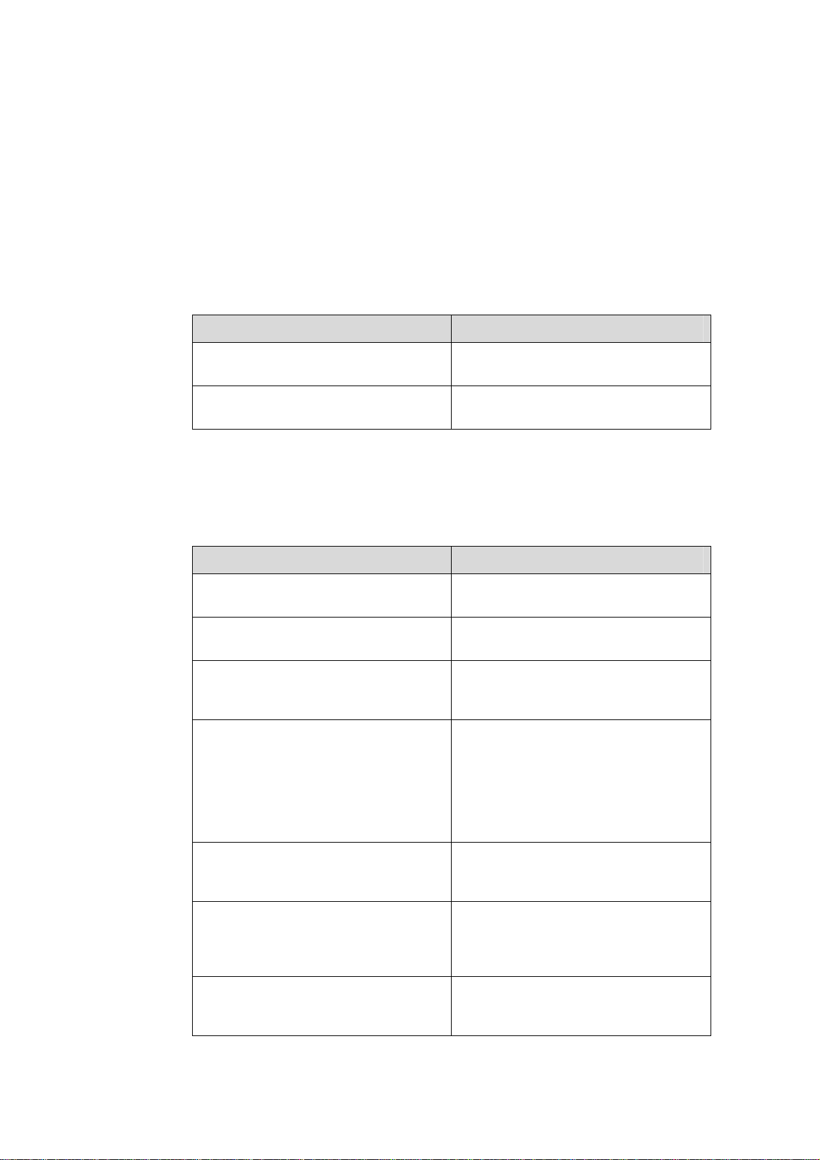
II. Symbols
Convention Description
Warning
Caution
Note Means a complementary description.
Environmental Protection
This product has been designed to comply with the requirements on environmental
protection. For the proper storage, use and disposal of this product, national laws and
regulations must be observed.
Means reader be extremely careful. Improper operation
may cause bodily injury.
Means reader be careful. Improper operation may cause
data loss or damage to equipment.
Page 5

Installation Manual
H3C S7502 Ethernet Switch Table of Contents
Table of contents
Chapter 1 Product Overview........................................................................................................1-1
1.1 General Information...........................................................................................................1-1
1.1.1 Preface....................................................................................................................1-1
1.1.2 Switching Engine..................................................................................................... 1-2
1.1.3 SRPU Specifications...............................................................................................1-2
1.2 LS81P12TE........................................................................................................................1-3
1.2.1 Specifications..........................................................................................................1-3
1.2.2 Panel and LEDs ...................................................................................................... 1-4
1.2.3 Port Cable ............................................................................................................... 1-5
1.3 LS81T12PE........................................................................................................................1-6
1.3.1 Specifications..........................................................................................................1-7
1.3.2 Panel and LEDs ...................................................................................................... 1-7
1.3.3 Port Cable ............................................................................................................... 1-8
1.4 LS81T16P.......................................................................................................................... 1-9
1.4.1 Specifications..........................................................................................................1-9
1.4.2 Panel and LEDs .................................................................................................... 1-10
1.4.3 Port Cable ............................................................................................................. 1-11
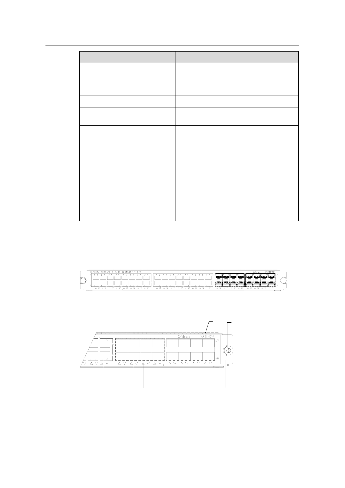
1.5 LS81T32P........................................................................................................................ 1-11
1.5.1 Specifications........................................................................................................1-11
1.5.2 Panel and LEDs .................................................................................................... 1-12
1.5.3 Port Cable ............................................................................................................. 1-13
1.6 LS81GT48B.....................................................................................................................1-13
1.6.1 Specifications........................................................................................................1-13
1.6.2 Panel and LEDs .................................................................................................... 1-14
1.6.3 Port Cable ............................................................................................................. 1-15
1.7 LS81GP48 ....................................................................................................................... 1-15
1.7.1 Specifications........................................................................................................1-15
1.7.2 Panel and LEDs .................................................................................................... 1-16
1.7.3 Port Cable ............................................................................................................. 1-17
1.8 LS81TGX2.......................................................................................................................1-17
1.8.1 Specifications........................................................................................................1-17
1.8.2 Panel and LEDs .................................................................................................... 1-18
1.8.3 Port Cable ............................................................................................................. 1-19
1.9 LS81TGX4.......................................................................................................................1-19
1.9.1 Specifications........................................................................................................1-19
1.9.2 Panel and LEDs .................................................................................................... 1-20
1.9.3 Port Cable ............................................................................................................. 1-21
1.10 LPUs Supported by SRPUs...........................................................................................1-21
i
Page 6

Installation Manual
H3C S7502 Ethernet Switch Table of Contents
1.11 Physical Description of the S7502................................................................................. 1-23
1.11.1 Chassis and Slots ...............................................................................................1-23
1.11.2 Color Description on the Fan Tray and Cards .................................................... 1-27
1.11.3 Backplane............................................................................................................1-28
1.11.4 Power Supply System.........................................................................................1-28
1.11.5 PoE Power Supply..............................................................................................1-29
1.11.6 Fan Tray.............................................................................................................. 1-30
1.12 Technical Specifications ................................................................................................ 1-31
ii
Page 7

Installation Manual
H3C S7502 Ethernet Switch Chapter 1 Product Overview
Chapter 1 Product Overview
1.1 General Information
1.1.1 Preface
H3C S7500 Series Ethernet Switches are modular, large-capacity Layer 2/3 Ethernet
switches that support wire-speed forwarding. The S7500 series include S7502, S7503,
S7506, and S7506R.
z The S7503, S7506, and S7506R are designed to operate at the convergence laye r
of IP metropolitan area networks (MANs) and at the core layer of small to
medium-sized enterprise networks and campus area networks.
z The S7502 is designed to operate at the core layer of small to medium-sized
enterprise networks and at the convergence layer and access layer of IP MANs.
The S7502 is a high-capacity, cost-effective Layer 3 Ethernet switch. It provides
high-density GE/FE ports, as well as modularized components that enable you to
configure flexibly according to your specific needs.
Figure 1-1 S7502 in a MAN
The S7502 supports 1+1 AC power redundancy backup, and provides one switching
and routing processing unit (SRPU) slot and one line processing unit (LPU) slot. Both
the SRPU and the LPU can provide high-density service ports.
1-1
Page 8

Installation Manual
H3C S7502 Ethernet Switch Chapter 1 Product Overview
1.1.2 Switching Engine
Switching engine (also known as SRPU) is the core of the S7502. Currently, switching
engines include the following models:
z LS81P12TE: provides four 10/100/1000Base-T ports and twelve 1000Base-X
(SFP) ports.
z LS81T12PE: provides twelve 10/100/1000Base-T ports and four 1000Base-X
(SFP) ports.
z LS81T16P: provides sixteen 10/100/1000Base-T ports and eight 1000Base-X
(SFP) ports, and supports XG high-speed bus.
z LS81T32P: provides thirty-two 10/100/1000Base-T ports and sixteen 1000Base-X
(SFP) ports, and supports XG high-speed bus.
z LS81GT48B: provides forty-eight 10/100/1000Base-T ports, and supports XG
high-speed bus.
z LS81GP48: provides forty-eight 1000Base-X (SFP) ports, and supports XG
high-speed bus.
z LS81TGX2: provides two 10GBase-XFP ports, and supports XG high-speed bus.
z LS81TGX4: provides four 10GBase-XFP ports and supports XG high-speed bus.
Note:
You can insert an SRPU into the second slot (slot 1) of the S7502 to serve as an LPU.
Generally an SRPU can provide these functions:
z L2/L3 data forwarding between LPUs
z Route calculation
z LPU monitoring
z Processing of the monitoring signals on the power system and fans
1.1.3 SRPU Specifications
The following table lists the SRPU specifications.
Table 1-1 SRPU specifications
Item
Switching
capacity
Packet
forwarding
rate
Number
of VLANs
MAC
address
table
Routing
table
LS81T12PE 48 Gbps 36 Mpps 4 K 16 K 64 K
LS81P12TE 48 Gbps 36 Mpps 4 K 16 K 64 K
LS81T16P 144 Gbps 108 Mpps 4 K 16 K 64 K
1-2
Page 9
Installation Manual
H3C S7502 Ethernet Switch Chapter 1 Product Overview
Item
Switching
capacity
Packet
forwarding
rate
Number
of VLANs
MAC
address
table
Routing
table
LS81T32P 192 Gbps 144 Mpps 4 K 16 K 64 K
LS81GT48B 192 Gbps 144 Mpps 4 K 16 K 64 K
LS81GP48 192 Gbps 144 Mpps 4 K 16 K 64 K
LS81TGX2 144 Gbps 108 Mpps 4 K 16 K 64 K
LS81TGX4 192 Gbps 144 Mpps 4 K 16 K 64 K
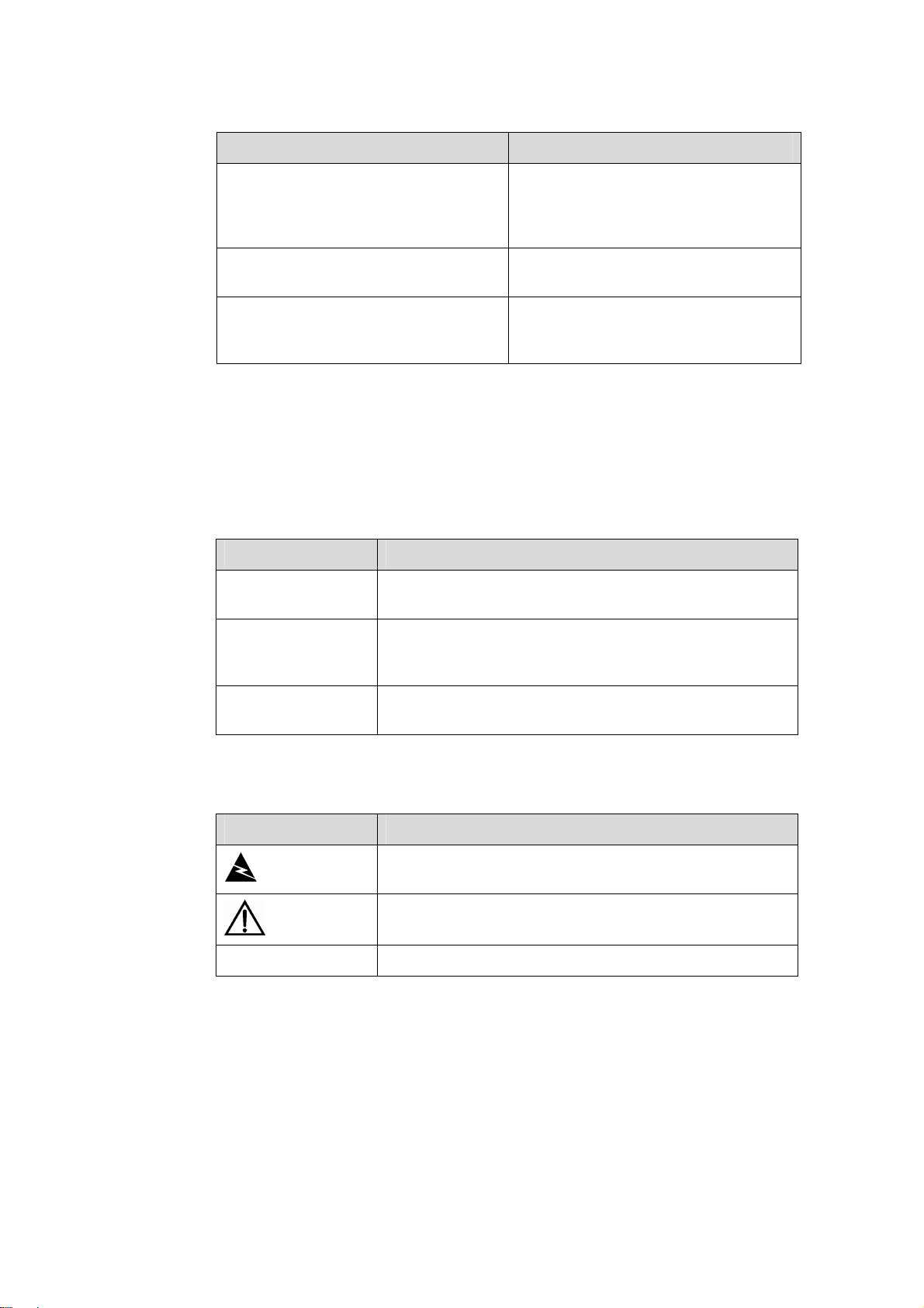
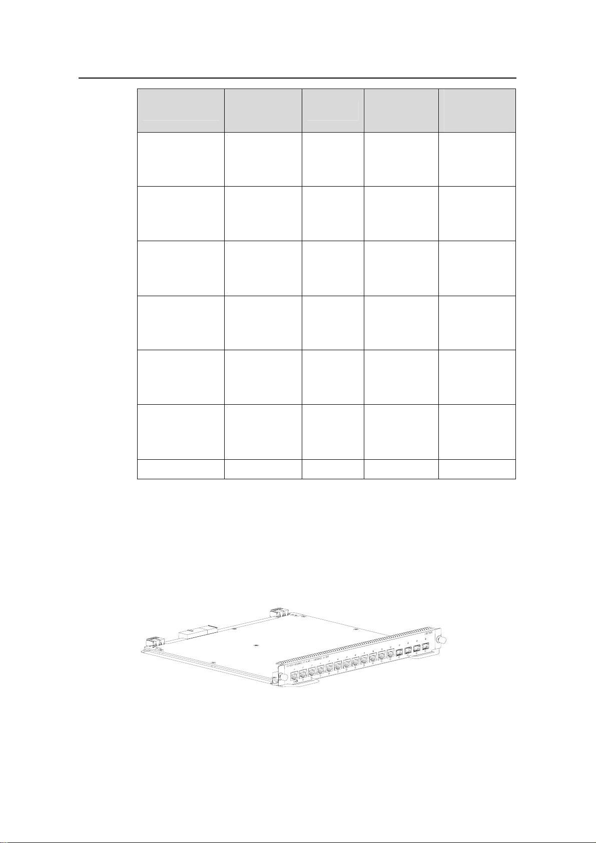
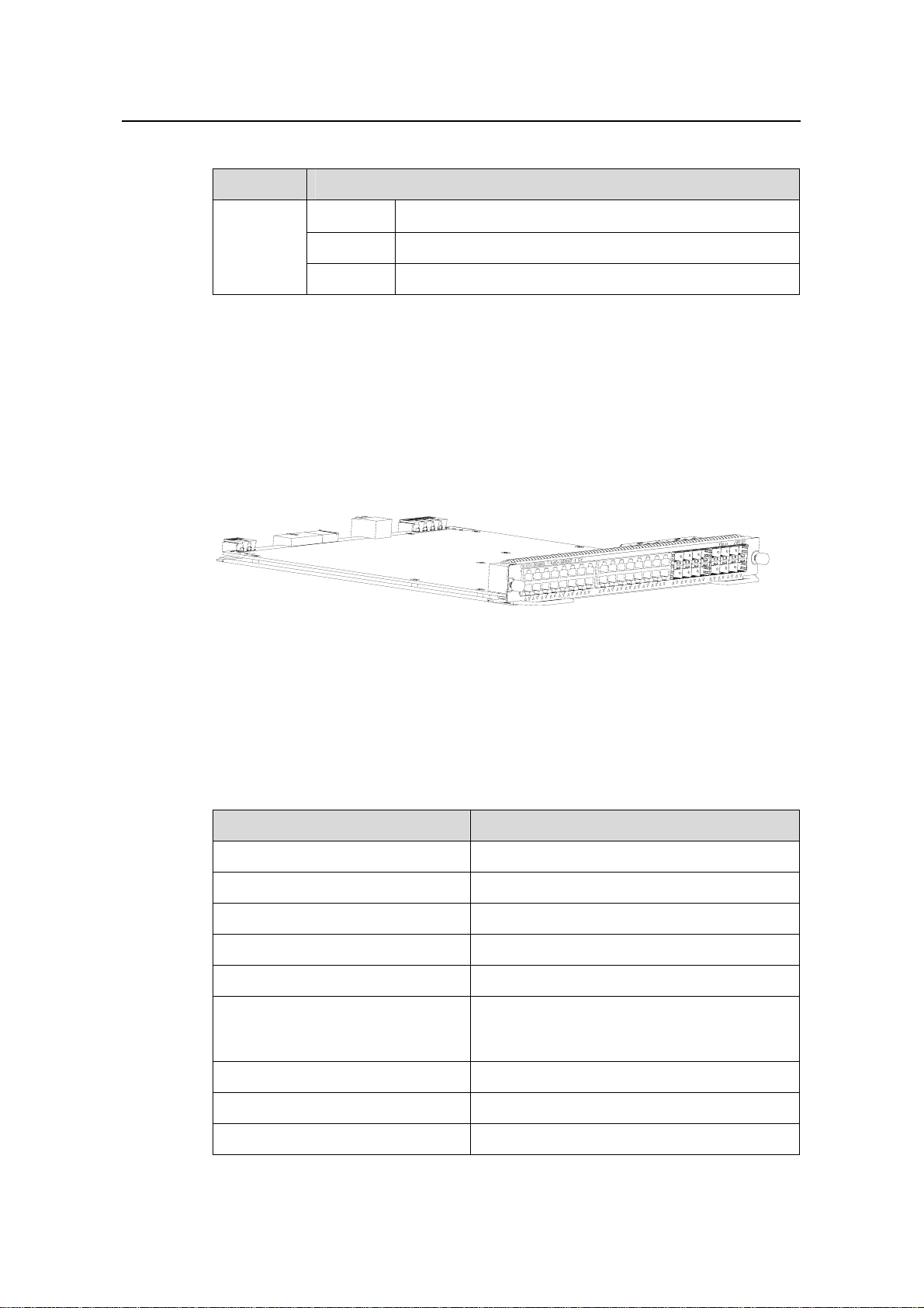
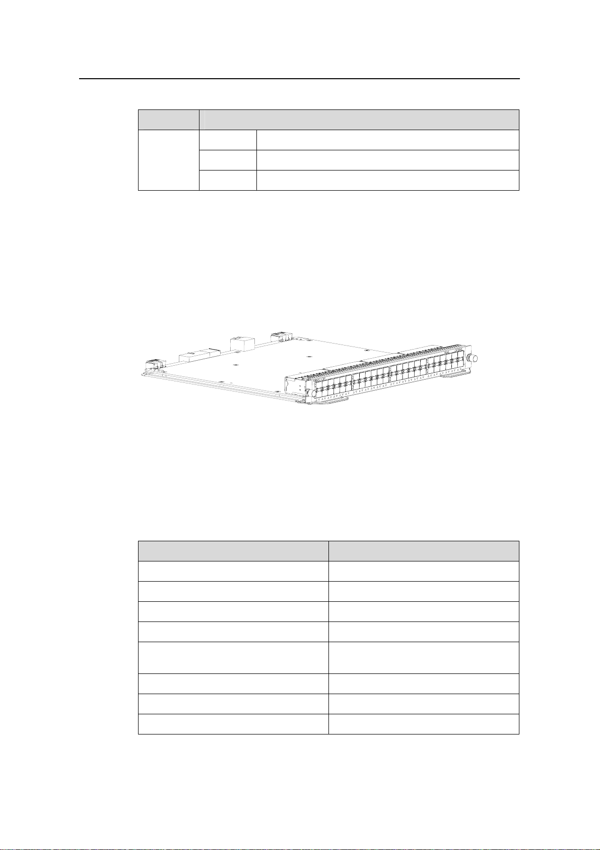
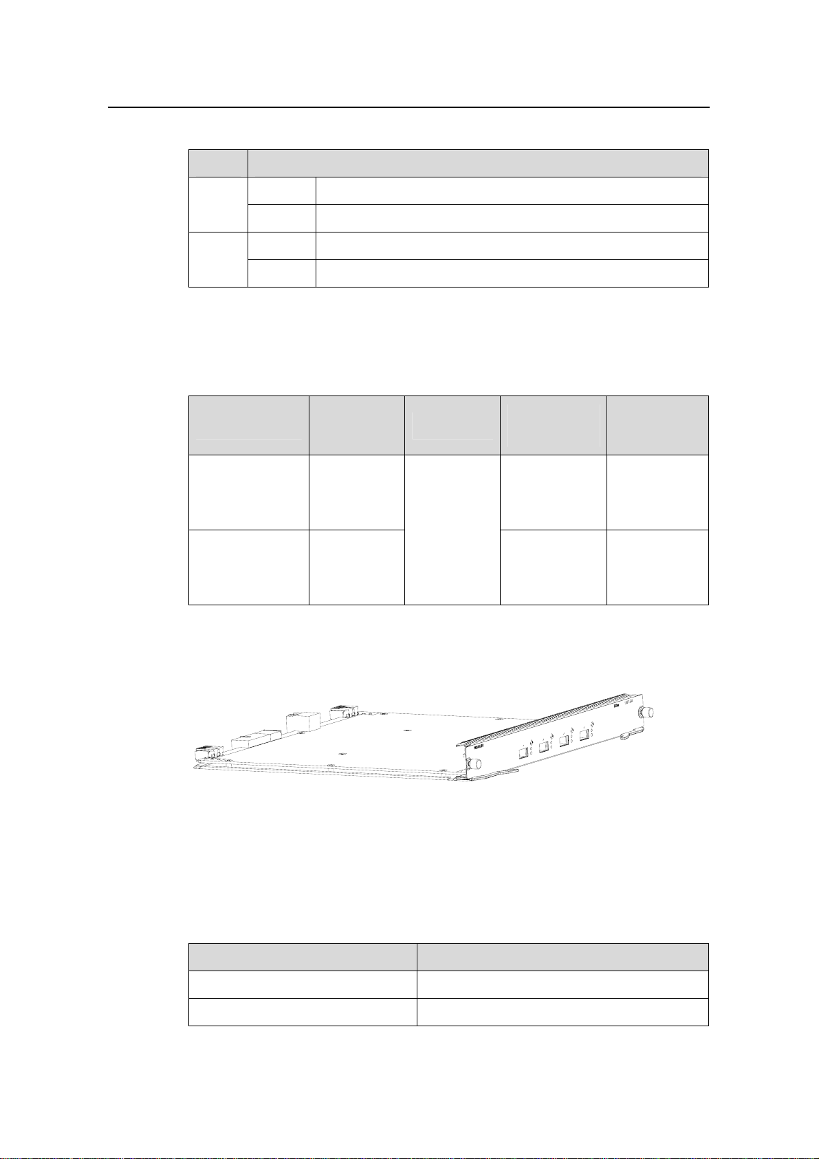
1.2 LS81P12TE
Figure 1-2 Appearance of an LS81P12TE
1.2.1 Specifications
Table 1-2 LS81P12TE specifications
CPU MPC8245 300 MHz
Boot ROM 512 KB
Flash memory 32 MB
SDRAM 256 MB
Dimensions (H × W x D)
Port
Max power consumption 40 W
Port rate
Item LS81P12TE
40.1 × 376.7 × 354.5 mm (1.6 × 14.8 × 14 in.)
z 4 × 10/100/1000Base-T Ethernet ports
z 12 × 1000Base-X (SFP) Ethernet ports
z 1000 Mbps full duplex (optical port)
z 10 Mbps half/full duplex (electrical port)
z 100 Mbps half/full duplex (electrical port)
z 1000 Mbps full duplex (electrical port)
SFP module Refer to Table 1-4
1-3
Page 10
Installation Manual
H3C S7502 Ethernet Switch Chapter 1 Product Overview
Item LS81P12TE
Ethernet port cable and max
transmission distance
Supported standard
100 m (328 ft) over category-5 twisted pair cable
z IEEE 802.3
z IEEE 802.3u
z IEEE 802.3z
z IEEE 802.3ab
z IEEE 802.1p
z IEEE 802.1Q
z IEEE 802.1D
z IEEE802.1X
z IEEE802.1s
z IEEE802.1w
z IEEE 802.3x
z IEEE 802.3ad
Note:
In this manual, card dimensions refer to those of a card with ejector levers.
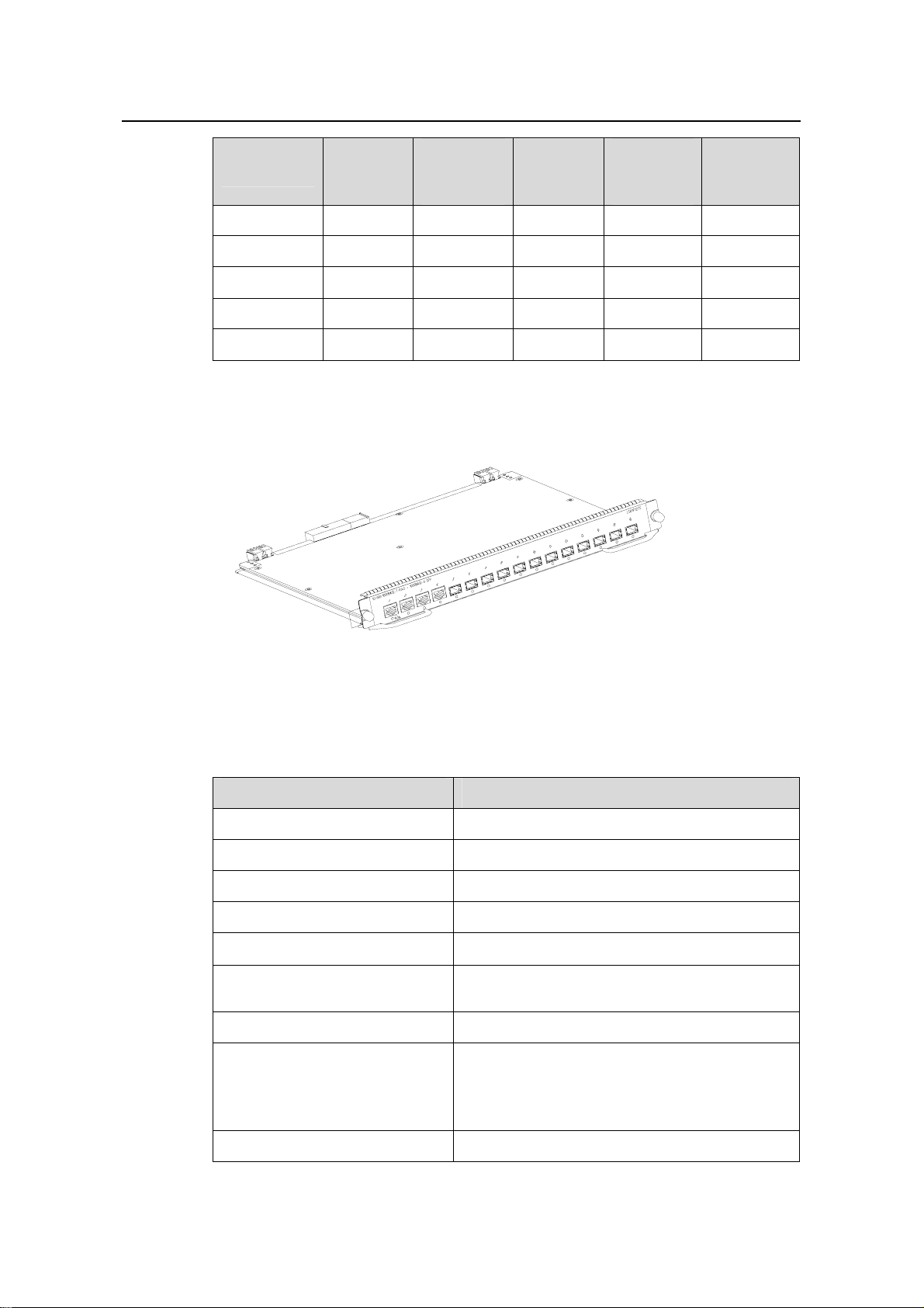
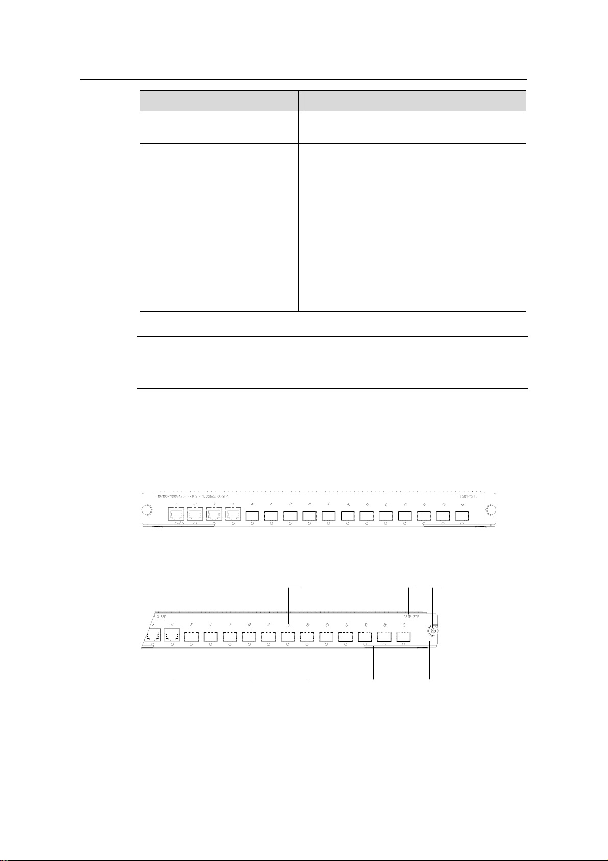
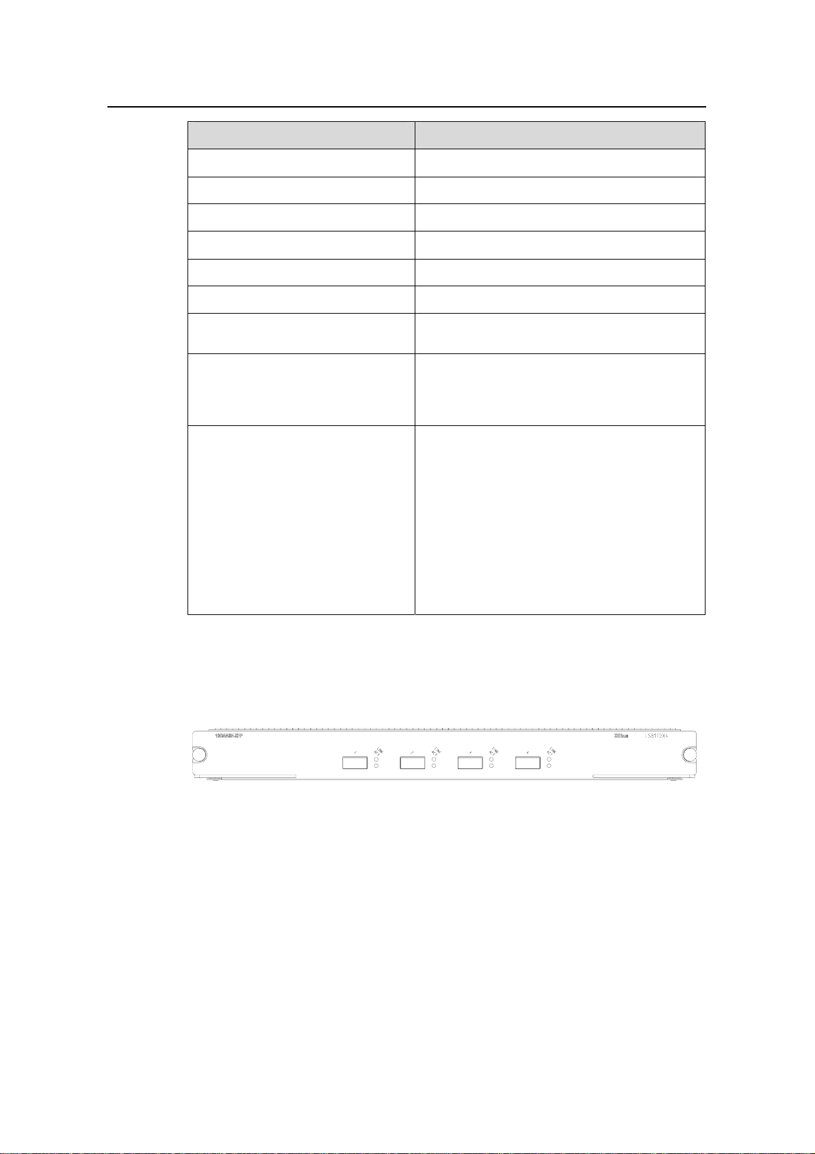
1.2.2 Panel and LEDs
LS81P12TE has four 10/100/1000Base-T ports and twelve 1000Base-X (SFP) ports;
each has a status LED with it.
Figure 1-3 LS81P12TE panel
(1) Interface number (2) Silkscreen
(3) Nut (4) LPU edge (Green)
(5) Ejector lever (6) Interface status indicator
(7) SPF port (Gigabit) (8) Ethernet port (Gigabit)
Figure 1-3 illustrates the panel of an LS81P12TE.
(1)
(7)(8)
(5)(6)
(2)
(3)
(4)
Figure 1-4 LS81P12TE panel
1-4
Page 11

Installation Manual
H3C S7502 Ethernet Switch Chapter 1 Product Overview
The status LEDs on an LS81P12TE are described in the following table.
Table 1-3 Description of LEDs on the panel of an LS81P12TE
LED Status
OFF The link is down or no link is presented.
LINK/ACT
1.2.3 Port Cable
I. Optical port cables for 12-port 1000Base-X (SFP)
Table 1-4 Description of 1000Base-X (SFP) port cables
SFP module
SFP-GE-SX-MM
850-A
ON The link is active.
Blinking Data is being transmitted or received on the port.
Central
wavelength
Connector
Matching
cable
Maximum
transmission
distance
50 µm/125 µm
multimode
optical fiber
550 m (1804
ft)
cable
850 nm LC
62.5 µm/125
µm multimode
optical fiber
275 m (902 ft)
cable
SFP-GE-LX-SM
1310-A
SFP-GE-LH40-S
M1310
SFP-GE-LH40-S
M1550
SFP-GE-LH70-S
M1550
SFP-GE-LH100SM1550
SFP-GE-LH70-S
M1470-CW
SFP-GE-LH70-S
M1490-CW
1310 nm LC
1550 nm LC
1470 nm LC
1490 nm LC
9 µm/125 µm
single mode
optical fiber
cable
9 µm/125 µm
single mode
optical fiber
cable
9 µm/125 µm
single mode
optical fiber
cable
9 µm/125 µm
single mode
optical fiber
cable
10 km (6 mi)
40 km (about
25 mi)
40 km (about
25 mi)
70 km (43 mi)
100 km (62 mi)
70 km (43 mi)
70 km (43 mi)
1-5
Page 12
Installation Manual
H3C S7502 Ethernet Switch Chapter 1 Product Overview
Maximum
transmission
distance
70 km (43 mi)
70 km (43 mi)
70 km (43 mi)
70 km (43 mi)
SFP module
SFP-GE-LH70-S
M1510-CW
SFP-GE-LH70-S
M1530-CW
SFP-GE-LH70-S
M1550-CW
SFP-GE-LH70-S
M1570-CW
Central
wavelength
1510 nm LC
1530 nm LC
1550 nm LC
1570 nm LC
Connector
Matching
cable
9 µm/125 µm
single mode
optical fiber
cable
9 µm/125 µm
single mode
optical fiber
cable
9 µm/125 µm
single mode
optical fiber
cable
9 µm/125 µm
single mode
optical fiber
cable
SFP-GE-LH70-S
M1590-CW
SFP-GE-LH70-S
M1610-CW
SFP-GE-T — RJ45 — 100 m (328 ft)
II. Ethernet port cable for 4-port 10/100/1000Base-T
The Ethernet port cable is category-5 twisted pair cable, ended with RJ45 connectors,
whose maximum transmission distance is 100 m.
1.3 LS81T12PE
1590 nm LC
1610 nm LC
9 µm/125 µm
single mode
optical fiber
cable
9 µm/125 µm
single mode
optical fiber
cable
70 km (43 mi)
70 km (43 mi)
Figure 1-5 Appearance of LS81T12PE
1-6
Page 13

Installation Manual
H3C S7502 Ethernet Switch Chapter 1 Product Overview
1.3.1 Specifications
Table 1-5 LS81T12PE specifications
Item LS81P12TE
CPU MPC8245 300 MHz
Boot ROM 512 KB
Flash memory 32 MB
SDRAM 256 MB
Dimensions (H × W x D)
Port
40.1 × 376.7 × 354.5 mm (1.6 × 14.8 × 14 in.)
z 12 × 10/100/1000Base-T Ethernet ports
z Four 1000Base-X (SFP) Ethernet ports
Max power consumption 45 W
Connector RJ-45, LC
Number of ports 16
z 1000 Mbps full duplex (optical port)
Port rate
z 10 Mbps half/full duplex (electric port)
z 100 Mbps half/full duplex (electric port)
z 1000 Mbps full duplex (electric port)
SFP module Refer to Table 1-4
Port cable and max transmission
distance
Supported standard
100 m (328 ft) over category-5 twisted pair
cable
z IEEE 802.3
z IEEE 802.3u
z IEEE 802.3z
z IEEE 802.3ab
z IEEE 802.1p
z IEEE 802.1Q
z IEEE 802.1D
z IEEE802.1X
z IEEE802.1s
z IEEE802.1w
z IEEE 802.3x
z IEEE 802.3ad
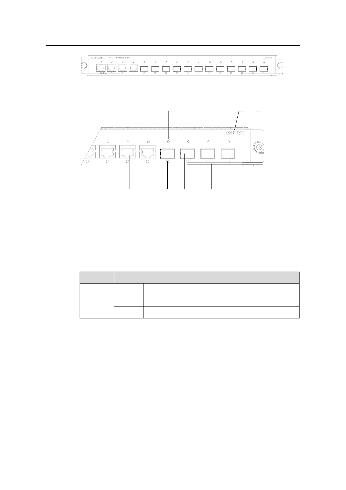
1.3.2 Panel and LEDs
LS81T12PE has 12 × 10/100/1000Base-T ports and four 1000Base-X (SFP) ports;
each has a status LED with it.
Figure 1-6 illustrates the panel of an LS81T12PE.
1-7
Page 14
Installation Manual
H3C S7502 Ethernet Switch Chapter 1 Product Overview
Figure 1-6 LS81T12PE panel
(1) (2)
(8)
(1) Interface number (2) Silkscreen
(3) Nut (4) LPU edge (Green)
(5) Ejector lever (6) SPF port (Gigabit)
(7) Interface status LED (8) Ethernet port (Gigabit)
(5)(6)(7)
Figure 1-7 LS81T12PE panel
The status LEDs on an LS81T12PE are described in
Table 1-6.
Table 1-6 Description of LEDs on the panel of an LS81T12PE
(4)
(3)
LED Status
LINK/ACT
1.3.3 Port Cable
Refer to section 1.2.3 "Port Cable” on page 1-5 for information about the port cable
required by an LS81T12PE.
OFF The link is down or no link is presented.
ON The link is active.
Blinking Data is being transmitted or received on the port.
1-8
Page 15
Installation Manual
H3C S7502 Ethernet Switch Chapter 1 Product Overview
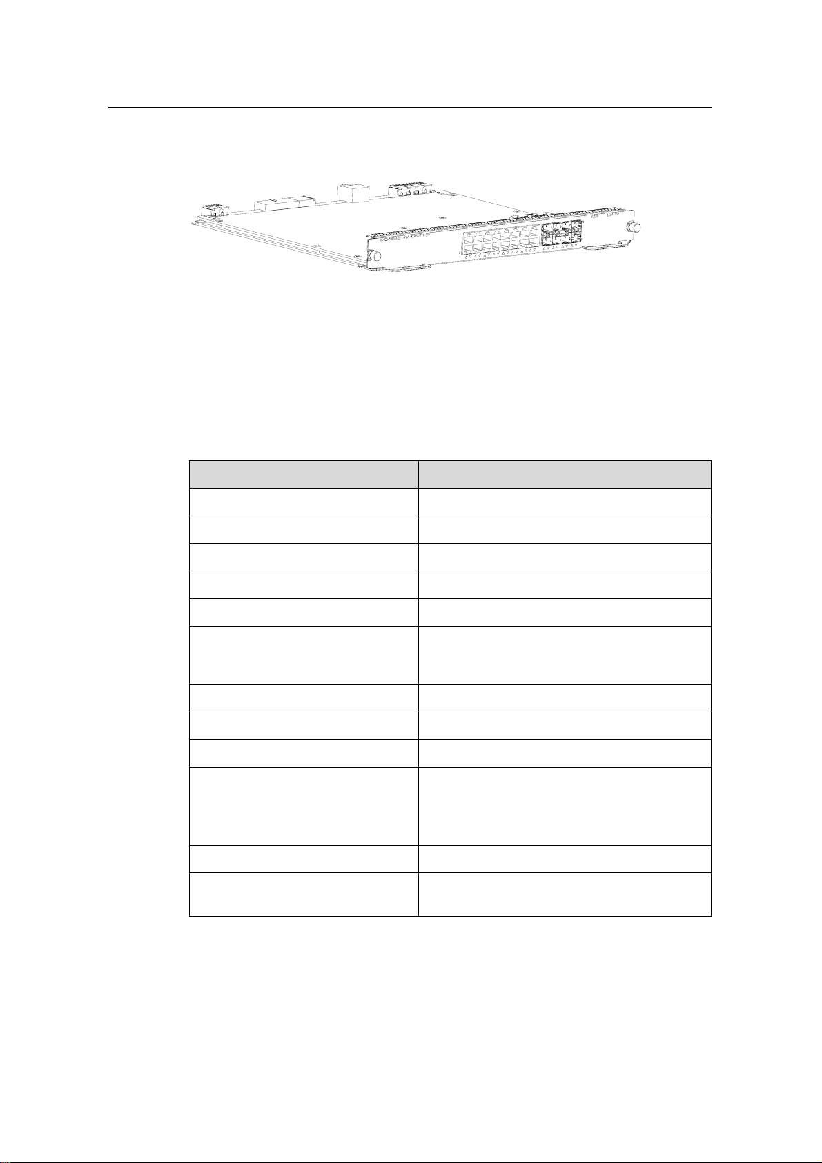
1.4 LS81T16P
Figure 1-8 Appearance of LS81T16P
1.4.1 Specifications
LS81T16P provides the XG high-speed bus and 16 × 10/100/1000Base-T ports and 8 ×
1000Base-X (SFP) ports.
Table 1-7 LS81T16P specifications
Item LS81T16P
CPU MPC8245 300 MHz
BootROM 512 KB
Flash memory 32 MB
SDRAM 256 MB
Dimensions (H × W x D) 40.1 × 376.7 × 354.5 mm (1.6 × 14.8 × 14 in.)
z 16 × 10/100/1000Base-T auto-sensing
Port
Ethernet electric ports
z 8 × 1000Base-X (SFP) Ethernet ports
Max power consumption 55 W
Connector RJ45, LC
Number of ports 24
z 10 Mbps half/full duplex
Port rate
z 100 Mbps half/full duplex
z 1000 Mbps full duplex
z MDI/MDI-X auto-sensing
SFP module Refer to Table 1-4
Port cable and max transmission
distance
100 m (328 ft) over category-5 twisted pair
cable
1-9
Page 16
Installation Manual
H3C S7502 Ethernet Switch Chapter 1 Product Overview
Item LS81T16P
z IEEE 802.3
z IEEE 802.3u
z IEEE 802.3z
z IEEE 802.3ab
z IEEE 802.1p
Supported standard
z IEEE 802.1Q
z IEEE 802.1D
z IEEE 802.1X
z IEEE 802.1s
z IEEE 802.1w
z IEEE 802.3x
z IEEE 802.3ad
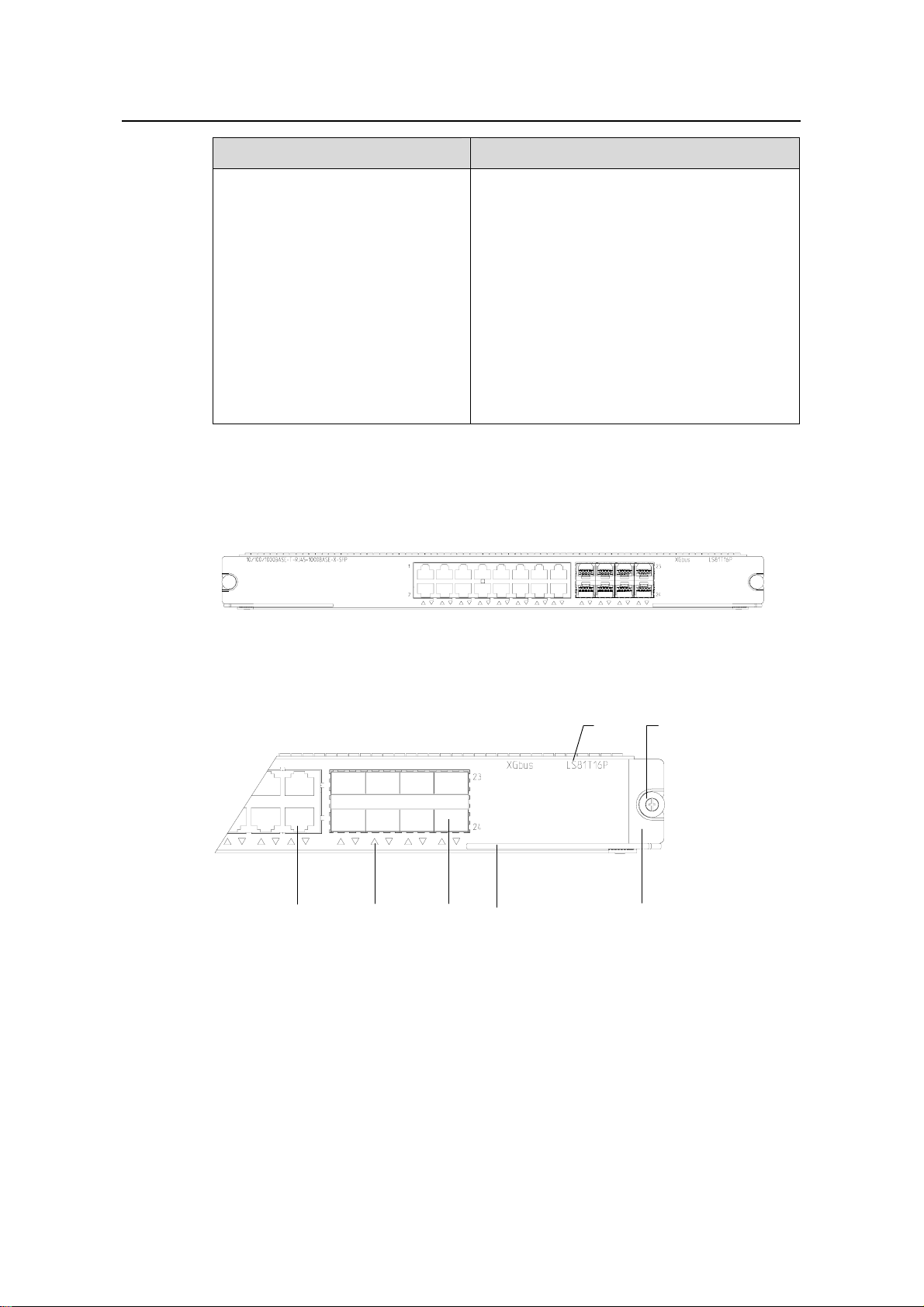
1.4.2 Panel and LEDs
The following figure illustrates the panel of an LS81T16P.
Figure 1-9 LS81T16P panel
(1) (2)
(5)(6)(7)
(1) Silkscreen (2) Nut
(3) LPU edge (Green) (4) Ejector lever
(5) SPF port (Gigabit) (6) Port status LED
(7) Ethernet port (Gigabit)
Figure 1-10 LS81T16P panel
(3)(4)
The status LEDs on an LS81T16P are described in following table
1-10
Page 17
Installation Manual
H3C S7502 Ethernet Switch Chapter 1 Product Overview
Table 1-8 Description of LEDs on the panel of an LS81T16P
LED Status
OFF The link is down or no link is presented.
LINK/ACT
1.4.3 Port Cable
Refer to section 1.2.3 "Port Cable” on page 1-5 for information about the port cable
required by an LS81T16P.
1.5 LS81T32P
Figure 1-11 Appearance of LS81T32P
1.5.1 Specifications
ON The link is active.
Blinking Data is being transmitted or received on the port.
LS81T32P provides the XG high-speed bus, 32 × 10/100/1000Base-T auto-sensing
Ethernet electric ports and 16 ×1000Base-X (SFP) Ethernet ports.
Table 1-9 LS81T32P specifications
Item LS81T32P
CPU MPC8245 300 MHz
BootROM 512 KB
Flash memory 32 MB
SDRAM 256 MB
Dimensions (H × W x D) 40.1 × 376.7 × 354.5 mm (1.6 × 14.8 × 14 in.)
z 32 × 10/100/1000Base-T auto-sensing
Port
Ethernet electric ports
z 16 × 1000Base-X (SFP) Ethernet ports
Max power consumption 95 W
Connector RJ45, LC
Number of ports 48
1-11
Page 18
Installation Manual
H3C S7502 Ethernet Switch Chapter 1 Product Overview
Item LS81T32P
z 10 Mbps half/full duplex
Port rate
z 100 Mbps half/full duplex
z 1000 Mbps full duplex
z MDI/MDI-X auto-sensing
SFP module Refer to Table 1-4
Port cable and max transmission
distance
Supported standard
1.5.2 Panel and LEDs
The following figure illustrates the panel of an LS81T32P.
100 m (328 ft) over category-5 twisted pair
cable
z IEEE 802.3
z IEEE 802.3u
z IEEE 802.3z
z IEEE 802.3ab
z IEEE 802.1p
z IEEE 802.1Q
z IEEE 802.1D
z IEEE 802.1X
z IEEE 802.1s
z IEEE 802.1w
z IEEE 802.3x
z IEEE 802.3ad
Figure 1-12 LS81T32P panel
(1) (2)
(5)(6)(7)
(4)
(3)
(1) Silkscreen (2) Nut
(3) LPU edge (Green) (4) Ejector lever
(5) Port status LED (6) SPF port (Gigabit)
(7) Ethernet port (Gigabit)
Figure 1-13 LS81T32P panel
1-12
Page 19
Installation Manual
H3C S7502 Ethernet Switch Chapter 1 Product Overview
The status LEDs on an LS81T32P are described in following table.
Table 1-10 Description of LEDs on the panel of an LS81T32P
LED Status
OFF The link is down or no link is presented.
LINK/ACT
1.5.3 Port Cable
Refer to section 1.2.3 "Port Cable” on page 1-5 for information about the port cable
required by an LS81T32P.
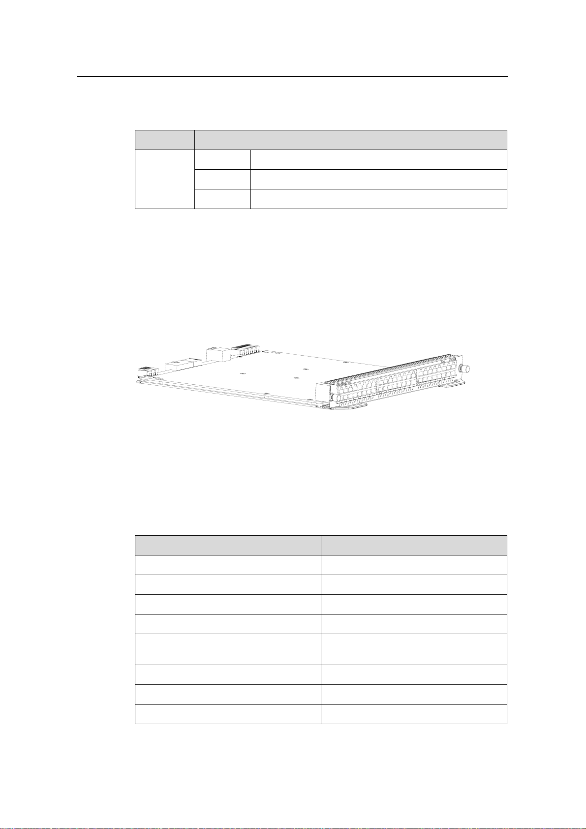
1.6 LS81GT48B
Figure 1-14 Appearance of LS81GT48B
1.6.1 Specifications
ON The link is active.
Blinking Data is being transmitted or received on the port.
LS81GT48B provides the XG high-speed bus, and 48 ×10/100/1000Base-T Ethernet
ports.
Table 1-11 LS81GT48B specifications
Item LS81GT48B
CPU MPC8245 300 MHz
BootROM 512 KB
Flash memory 32 MB
SDRAM 256 MB
Dimensions (H × W x D)
Max power consumption 85 W
Connector RJ45
Number of ports 48
1-13
40.1 × 376.7 × 354.5 mm (1.6 × 14.8 ×
14 in.)
Page 20
Installation Manual
H3C S7502 Ethernet Switch Chapter 1 Product Overview
Item LS81GT48B
z 10 Mbps half/full duplex
Port rate
z 100 Mbps half/full duplex
z 1000 Mbps half/full duplex
z MDI/MDI-X auto-sensing
Port cable and max transmission
distance
Supported standard
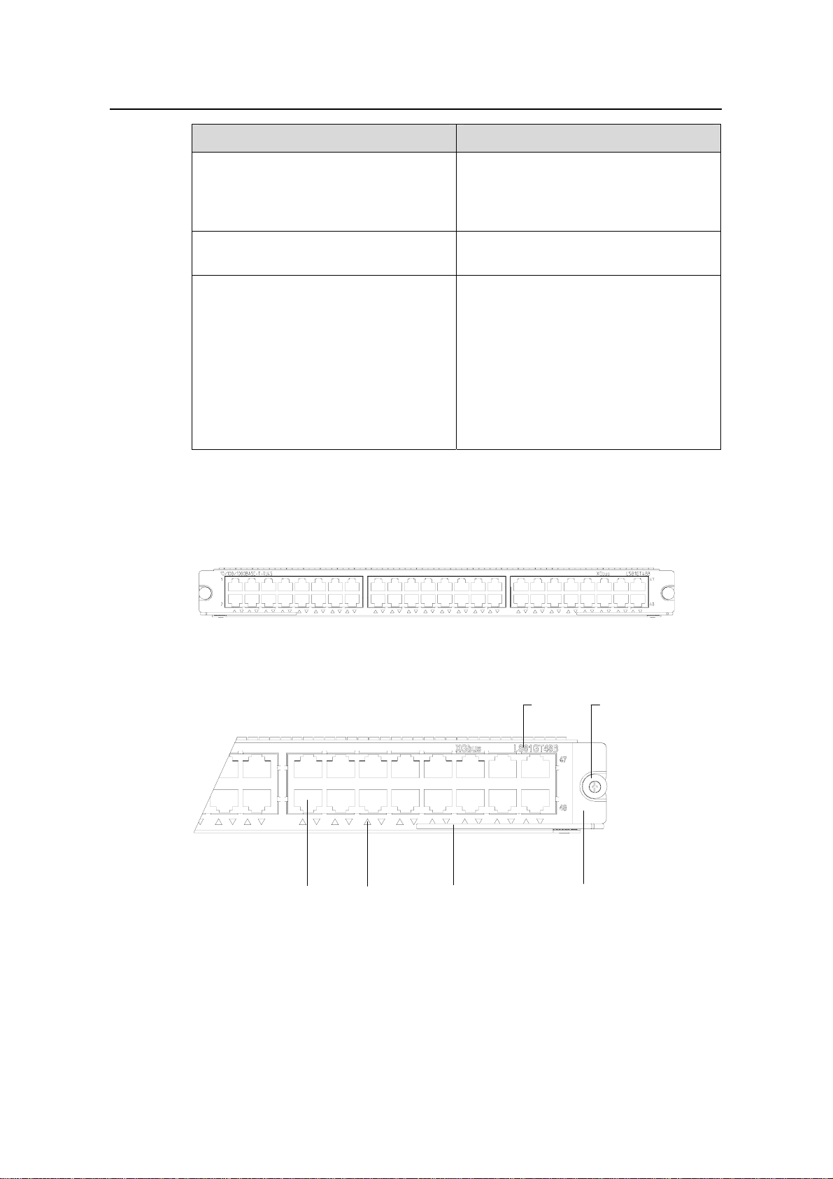
1.6.2 Panel and LEDs
The following figure illustrates the panel of an LS81GT48B.
Figure 1-15 LS81GT48B panel
100 m (328 ft) over category-5 twisted
pair cable
z IEEE 802.3
z IEEE 802.3ab
z IEEE 802.3x
z IEEE 802.1p
z IEEE 802.1D
z IEEE 802.1Q
z IEEE 802.1X
z IEEE 802.1s
z IEEE 802.1w
(1) (2)
(5)(6)
(4)
(1) Silkscreen (2) Nut
(3) LPU edge (Green) (4) Ejector lever
(5) Ethernet port LED (6) Ethernet port
Figure 1-16 LS81GT48B panel
Each port is with a green LED.
1-14
(3)
Page 21
Installation Manual
H3C S7502 Ethernet Switch Chapter 1 Product Overview
Table 1-12 Description of LEDs on the panel of an LS81GT48B
LED Status
OFF The link is down or no link is presented.
LINK/ACT
1.6.3 Port Cable
The port cable is category-5 twisted pair cable conne cted with RJ45 connectors, whose
maximum transmission distance is 100 m.
1.7 LS81GP48
Figure 1-17 Appearance of LS81GP48
ON The link is active.
Blinking Data is being transmitted or received on the port.
1.7.1 Specifications
LS81GP48 provides the XG high-speed bus, and 48 ×10/100/1000Base-T Ethernet
ports.
Table 1-13 LS81GP48 specifications
CPU MPC8245 300 MHz
BootROM 512 KB
Flash memory 32 MB
SDRAM 256 MB
Dimensions (H × W x D)
Max power consumption 75 W
Connector LC
Number of ports 48
Item LS81GP48
40.1 × 376.7 × 354.5 mm (1.6 × 14.8 ×
14 in.)
1-15
Page 22
Installation Manual
H3C S7502 Ethernet Switch Chapter 1 Product Overview
Item LS81GP48
Port rate
SFP module Refer to Table 1-4
Supported standard
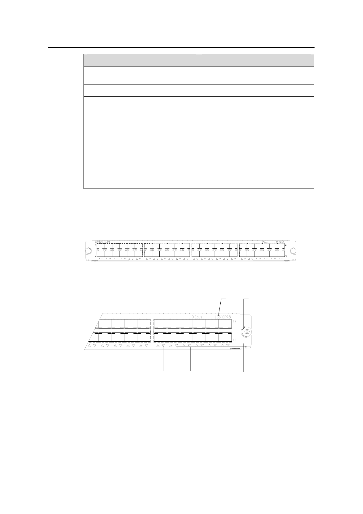
1.7.2 Panel and LEDs
The following figure illustrates the panel of an LS81GP48.
z 1000 Mbps
z Full duplex
z IEEE 802.3
z IEEE 802.3u
z IEEE 802.3z
z IEEE 802.1p
z IEEE 802.1Q
z IEEE 802.1D
z IEEE 802.3x
z IEEE 802.1X
z IEEE 802.1w
z IEEE 802.3ad
z IEEE 802.1s
Figure 1-18 LS81GP48 panel
(1) (2)
(5)(6)
(4)
(3)
(1) Silkscreen (2) Nut
(3) LPU edge (Green) (4) Ejector lever
(5) Ethernet port LED (6) SFP interface
Figure 1-19 LS81GP48 panel
The status LEDs on an LS81GP48 are described in following table.
1-16
Page 23
Installation Manual
H3C S7502 Ethernet Switch Chapter 1 Product Overview
Table 1-14 Description of LEDs on the panel of an LS81GP48
LED Status
OFF The link is down or no link is presented.
LINK/ACT
1.7.3 Port Cable
Refer to Table 1-4.
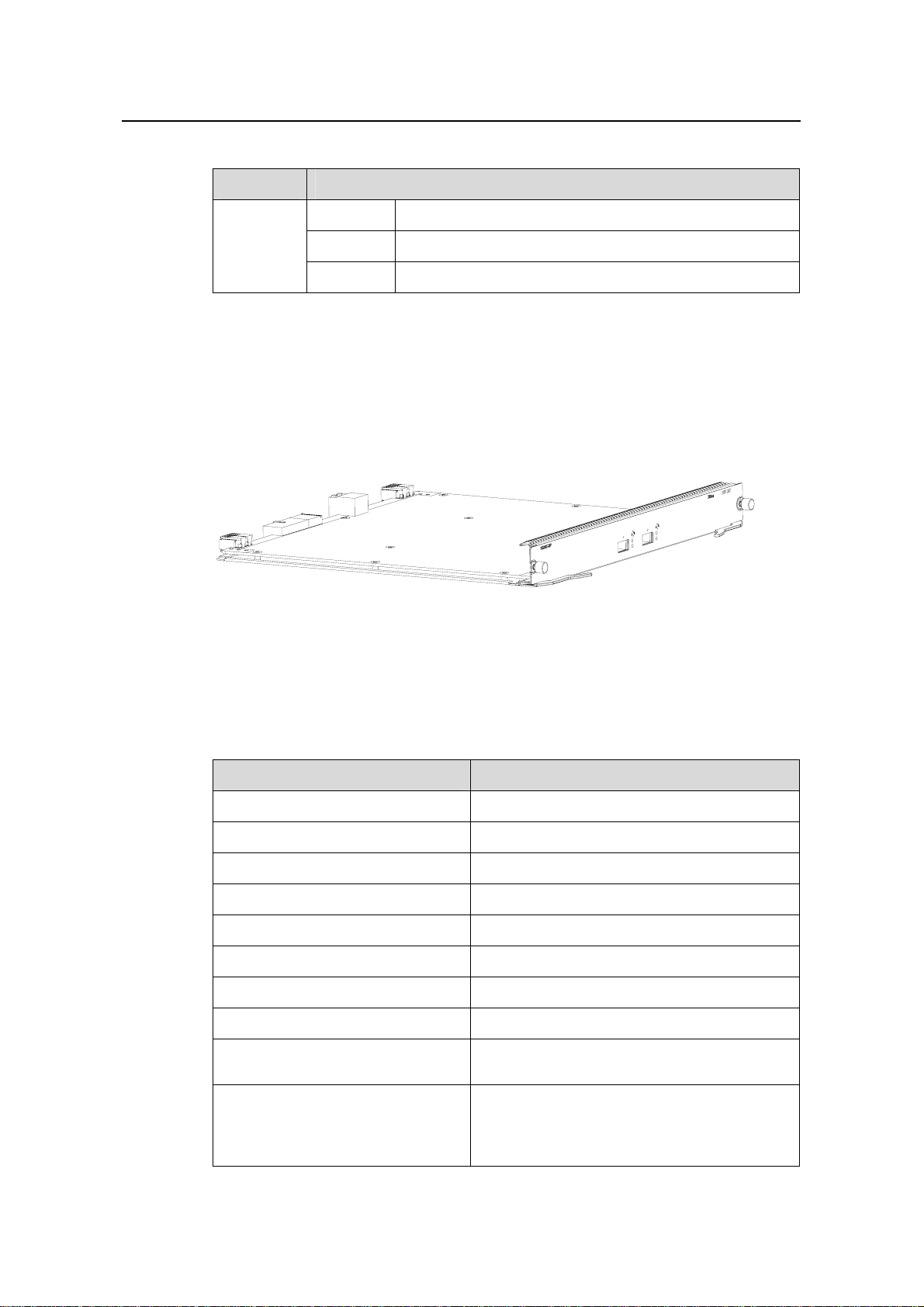
1.8 LS81TGX2
Figure 1-20 Appearance of LS81TGX2
1.8.1 Specifications
ON The link is active.
Blinking Data is being transmitted or received on the port.
LS81TGX2 provides the XG high-speed bus and two full duplex 10GBase-XFP ports.
Table 1-15 LS81TGX2 specifications
Item LS81TGX2
CPU MPC8245 300 MHz
BootROM 512 KB
Flash memory 32 MB
SDRAM 256 MB
Dimensions (H × W x D) 40.1 × 376.7 × 354.5 mm (1.6 × 14.8 × 14 in.)
Max power consumption 35 W
Connector LC
Number of ports 2
Port rate
XFP module
z 10 Gbps
z Full duplex
z XFP-LX-SM1310 (single mode optical
fiber, 1310 nm, 10 km [6.2 mi] )
z XFP-SX-MM850 (multimode optical fiber,
850 nm, 300 m [984 ft] )
1-17
Page 24
Installation Manual
H3C S7502 Ethernet Switch Chapter 1 Product Overview
Item LS81TGX2
z IEEE 802.3
z IEEE 802.1p
z IEEE 802.1Q
z IEEE 802.1D
Supported standard
z IEEE 802.3x
z IEEE 802.3ad
z IEEE 802.3ae
z IEEE 802.1X
z IEEE 802.1s
z IEEE 802.1w
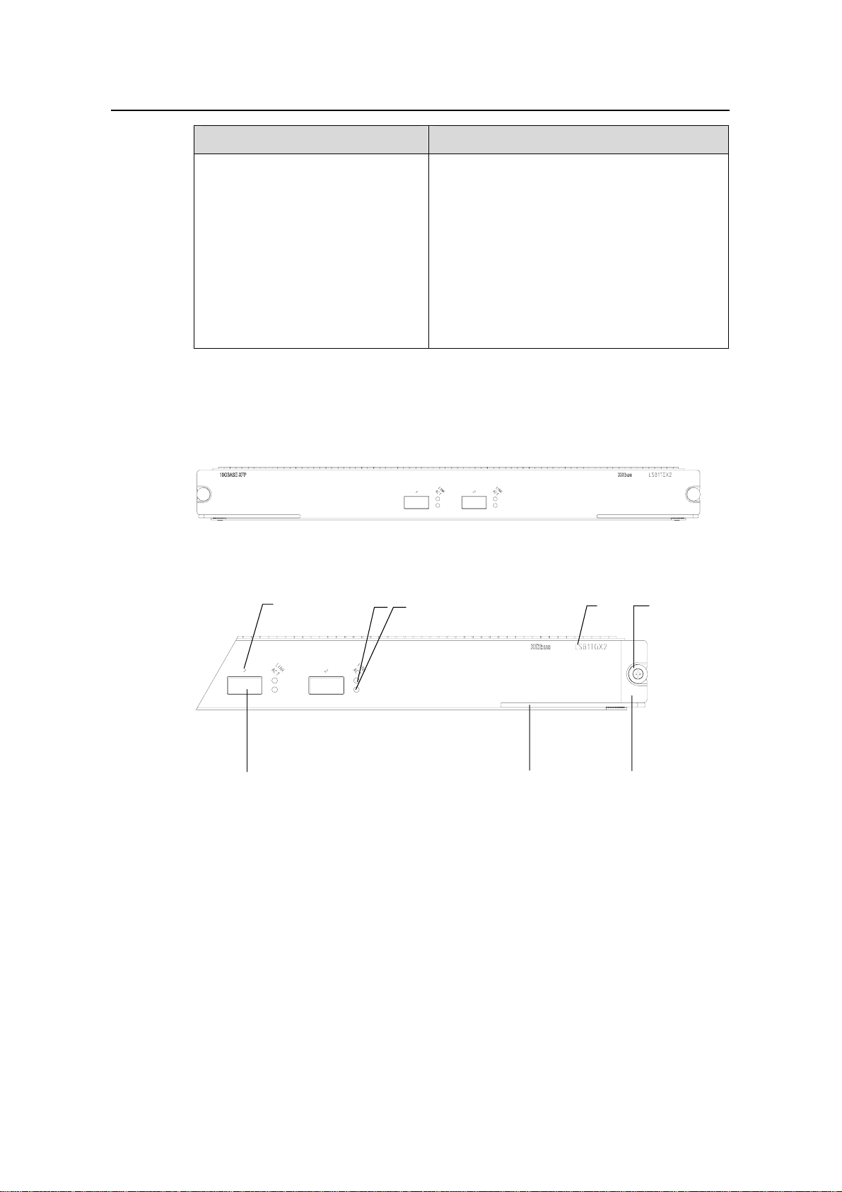
1.8.2 Panel and LEDs
The following figure illustrates the panel of an LS81TGX2.
Figure 1-21 LS81TGX2 panel
(1)
(3) (4)
(2)
(8)
(1) Interface number (2) Interface status LED (LINK)
(3) Interface status LED (ACT) (4) Silkscreen
(5) Nut (6) LPU edge (Green)
(7) Ejector lever (8) XFP module interface (10 Gigabit)
(5)
(6)(7)
Figure 1-22 LS81TGX2 panel
The status LEDs on an LS81TGX2 are described in following table.
1-18
Page 25
Installation Manual
H3C S7502 Ethernet Switch Chapter 1 Product Overview
Table 1-16 Description of LEDs on the panel of an LS81TGX2
LED Status
LINK
ACT
1.8.3 Port Cable
Table 1-17 Description on the port cables for LS81TGX2
XFP module
XFP-SX-MM850 850 nm
XFP-LX-SM1310 1310 nm
OFF The link is down or no link is presented.
ON The link is active.
OFF No data is being transmitted or received on the port
Blinking Data is being transmitted or received on the port.
Central
wavelength
Connector
LC
Matching
cable
50 µm/125 µm
multimode
optical fiber
cable
9 µm/125 µm
single mode
optical fiber
cable
Maximum
transmission
300 m (984 ft)
10 km (6 mi)
distance
1.9 LS81TGX4
Figure 1-23 Appearance of LS81TGX4
1.9.1 Specifications
LS81TGX4 provides the XG high-speed bus and four full duplex 10GBase-XFP ports.
Table 1-18 LS81TGX4 specifications
CPU MPC8245 300 MHz
BootROM 512 KB
Item LS81TGX4
1-19
Page 26
Installation Manual
H3C S7502 Ethernet Switch Chapter 1 Product Overview
Item LS81TGX4
Flash memory 32 MB
SDRAM 256 MB
Dimensions (H × W x D) 40.1 × 376.7 × 354.5 mm (1.6 × 14.8 × 14 in.)
Max power consumption 55 W
Connector LC
Number of ports 4
Port rate
XFP module
Supported standard
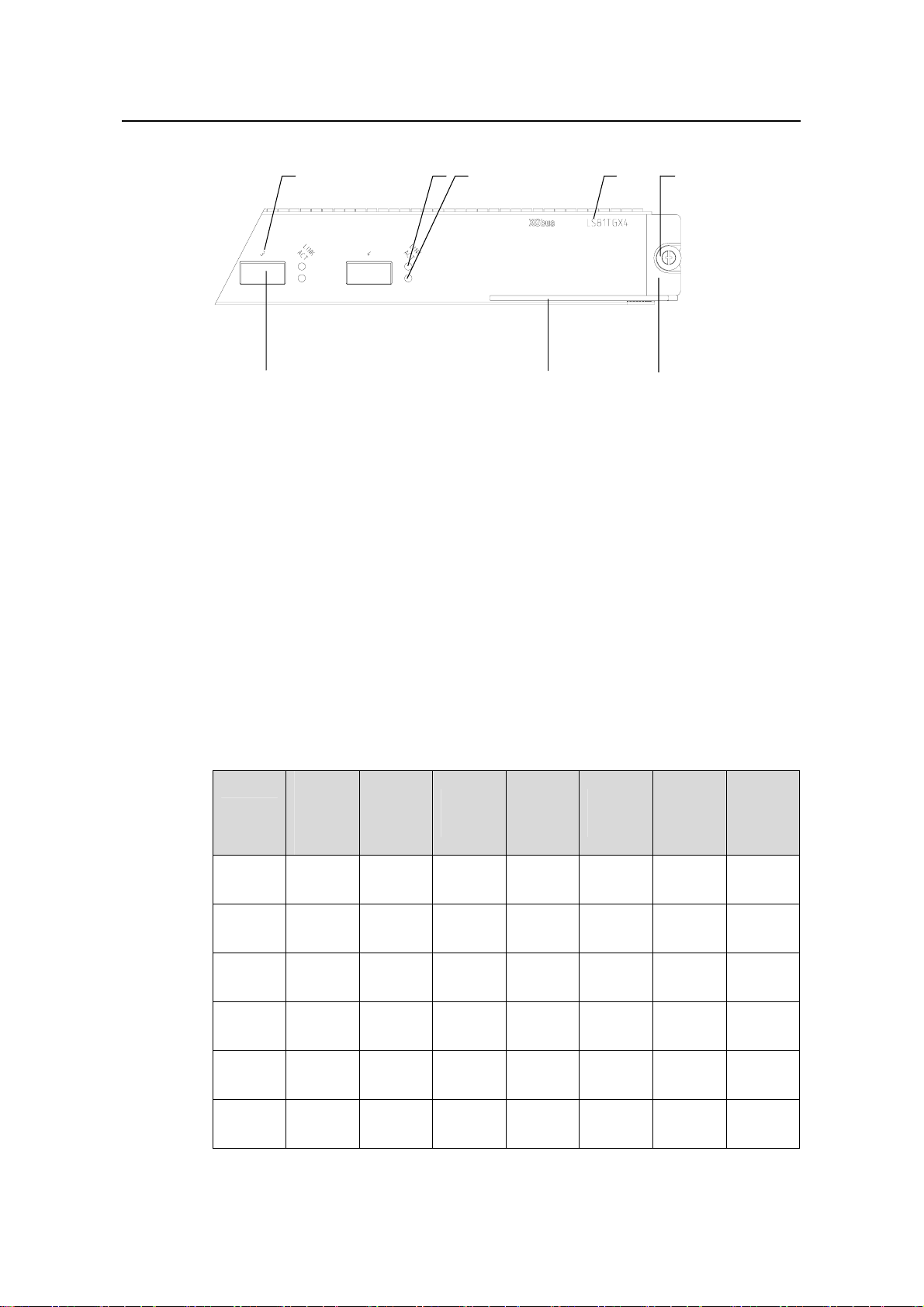
1.9.2 Panel and LEDs
The following figure illustrates the panel of an LS81TGX4.
z 10 Gbps
z Full duplex
z XFP-LX-SM1310 (single mode optical
fiber, 1310 nm, 10 km [6.2 mi] )
z XFP-SX-MM850 (multimode optical fiber,
850 nm, 300 m [984 ft] )
z IEEE 802.3
z IEEE 802.1p
z IEEE 802.1Q
z IEEE 802.1D
z IEEE 802.3x
z IEEE 802.3ad
z IEEE 802.3ae
z IEEE 802.1X
z IEEE 802.1s
z IEEE 802.1w
Figure 1-24 LS81TGX4 panel
1-20
Page 27
Installation Manual
H3C S7502 Ethernet Switch Chapter 1 Product Overview
(1) Interface number (2) Interface status LED (LINK)
(3) Interface status LED (ACT) (4) Silkscreen
(5) Nut (6) LPU edge (Green)
(7) Ejector lever (8) XFP module interface (10 Gigabit)
Figure 1-25 LS81TGX4 panel
Refer to
1.9.3 Port Cable
(1) (2) (3)
(7)
(4)
Table 1-16 for the description of LEDs on an LS81TGX4.
(6)(8)
(5)
Refer to Table 1-4.
1.10 LPUs Supported by SRPUs
I. LPUs supported by SRPUs
Table 1-19 LPUs supported by SRPUs
LS81T1
Item
LS81FT
48E
LS81FT
48F
LS81FP
48
LS81G
T8UE
LS82G
T20
2PE/
LS81P1
2TE
√ — — — — — —
√ — — — — — —
√
√
√
LS81T1
6P
—
—
—
LS81T3
2P
—
—
—
LS81G
T48B
—
—
—
LS81G
P48
—
—
—
LS81T
GX2
—
—
—
LS81T
GX4
—
—
—
LS82G
T20A
√
—
—
1-21
—
—
—
—
Page 28

Installation Manual
H3C S7502 Ethernet Switch Chapter 1 Product Overview
LS81T1
Item
2PE/
LS81P1
LS81T1
6P
LS81T3
2P
LS81G
T48B
LS81G
P48
LS81T
GX2
LS81T
GX4
2TE
LS81G
T48
LS81G
T48A
LS81G
T48B
LS81T1
2P
LS81T1
2PE
LS81T1
6P
LS81T3
2P
LS81P1
2T
LS81P1
2TE
LS81G
P8UB
√
√
√ √ √ √ √ √
—
√
√
√ √ √ √ √ √
—
√ √ √ √ √ √
—
√
√
√
—
—
—
—
—
—
—
—
—
—
—
—
—
—
—
—
—
—
—
—
—
—
—
—
—
—
—
—
—
—
—
—
—
—
—
—
—
—
—
—
—
—
LS82G
P20
LS82G
P20A
LS81G
P48
LS81T
GX1C
LS81T
GX2
LS81T
GX4
LS81V
SNP
√
√
√ √ √ √ √ √
—
√
√ √ √ √ √ √
—
√ √ √ √ √ √
—
√ √ √ √ √ √
—
—
—
—
—
—
—
—
—
—
—
—
—
II. Introduction to LPUs
z LS81FT48E: provides forty-eight 10Base-T/100Base-TX ports.
—
—
—
—
—
—
1-22
Page 29

Installation Manual
H3C S7502 Ethernet Switch Chapter 1 Product Overview
z LS81FT48F: provides forty-eight 10Base-T/100Base-TX ports; supports the PoE
function.
z LS81FP48: provides forty-eight 100Base-FX (SFP) ports.
z LS81GT8UE: provides eight 10/100/1000Base-T ports.
z LS82GT20: provides twenty 10/100/1000Base-T ports.
z LS82GT20A: provides twenty 10/100/1000Base-T ports.
z LS81GT48: provides forty-eight 10/100/1000Base-T ports.
z LS81GT48A: provides forty-eight 10/100/1000Base-T ports and supports PoE
function.
z LS81T12P: provides twelve 10/100/1000Base-T ports and four 1000Base-X (SFP)
ports.
z LS81P12T: provides four 10/100/1000Base-T ports and twelve 1000Base-X (SF P)
ports.
z LS81GB8UA: provides eight 1000Base-X (SFP) ports.
z LS82GP20: provides twenty 1000Base-X (SFP) ports.
z LS82GP20A: provides twenty 1000Base-X (SFP) ports.
z LS81TGX1C: provides one 10GBase-R-XENPAK port.
z LS81VSNP: provides no service port, supports the XG high-speed bus, features
high performance network processor (NP) and CPU, and assists other LPUs to
provide functions of policy-based routing, network address translation (NAT), and
Netstream.
1.11 Physical Description of the S7502
1.11.1 Chassis and Slots
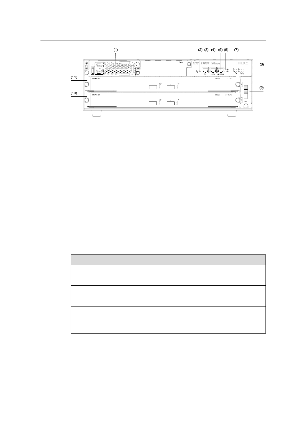
I. Front view
The S7502 chassis uses an XG high-speed bus and XGbus is silkscreened on the
chassis.
Power supply module slots, RESET button, COM port (for PoE management), console
port, 10Base-T/100Base-TX management port and its status LED, fan LED, and card
status LED are in sequence arranged on the front panel.
The S7502 chassis provides two horizontal slots. An SRPU is required in slot 0 and
does not support active-standby switchover), while an LPU is optional in slot 1..
Figure 1-26 illustrates the front view of an S7502, where an LS81TGX2 is inserted in
slot 0 and slot 1, respectively. The LS81TGX2 in slot 0 serves as an SRPU, while the
LS81TGX2 in slot 1 serves as an LPU.
1-23
Page 30
Installation Manual
H3C S7502 Ethernet Switch Chapter 1 Product Overview
(1) Power module (2) RESET button
(3) COM port (4) Console port
(5) Ethernet port for management and
upgrade
(7) Fan LED (8) Card status LED
(9) Fan tray (10) LPU
(11) SRPU
(6) LED of Ethernet port for management and
upgrade
Figure 1-26 Panel of an S7502 switch (an AC chassis in an example)
z Power modules
The power modules, in 1+1 redundancy backup, ar e at the top left corner of the chassis
to provide AC power supply. There are LED, power switch and power input socket on a
power supply module (refer to
z RESET button
Figure 1-31 for more information).
You can reset the system with the RESET button.
COM port
Table 1-20 COM port attributes
Item Description
Connector RJ45
Number of connector 1
Supported standard Asynchronous EIA/TIA-232
Baudrate
Transmission distance
Function
≤ 115,200 bps (defaults to 9,600 bps)
≤ 15 m (49.2 ft)
For monitoring external PoE power
supply when connected to it
1-24
Page 31

Installation Manual
H3C S7502 Ethernet Switch Chapter 1 Product Overview
Note:
The S7502 provides an independent power over Ethernet (PoE) module and can
remotely provide power to powered devices (PDs), such as IP phone sets, WLAN
access points (APs). There are S7502 PoE chassis and non-PoE chassis. If the PoE
function is required, select an S7502 PoE chassis.
z Console port
The Console port matches RJ45 connector and can be connected to a PC with an
asynchronous serial port cable, for local system debugging, configuration,
maintenance, management, system software loading and so o n. It also can be used to
connect to a Modem device for remote debugging, configuration, maintenance,
management and other similar tasks.
Table 1-21 Console port attributes
Item Description
Connector RJ45
Number of connector 1
Electric standard Asynchronous EIA/TIA-232
Baud rate
Transmission distance
Function
≤ 115,200 bps, defaults to 9,600 bps
≤ 15 m (49.2 ft)
z For connection with an ASCII terminal
z Being connected to the serial interface of a local
PC or a remote PC (through a pair of Modems)
running terminal emulation software
z Ethernet interface for management and upgrade (10Base-T/100Base-TX)
The management port matches RJ45 connector and can be used to connect to a PC for
local system debugging, system software loading and other similar tasks, or to a
remote a network management station (NMS) for remote managem ent.
Table 1-22 Attributes of Ethernet interface for management and upgrade
Item Description
Connector RJ45
Number of connector 1
z 10 Mbps, half/full duplex
Port rate
1-25
z 100 Mbps, half/full duplex
z MDI-X
Page 32

Installation Manual
H3C S7502 Ethernet Switch Chapter 1 Product Overview
Item Description
Port cable and max transmission
distance
Function
100 m (328 ft) over category-5 twisted
pair cable
For system software upgrade and
network management
The corresponding LEDs are described in the following table.
Table 1-23 Management port status LEDs
LED Status
LINK
(Green)
ACT
(Green)
OFF No link is presented.
ON A link is presented.
OFF No data traffic through the port
Blinking Data is being transmitted or received on the port.
z Fan tray status LEDs (FAN)
Table 1-24 Fan tray status LEDs
LED Status
OK
(Green)
FAIL
(Green)
OFF A fan is faulty or out of position.
ON The fans run normally.
OFF The fans run normally.
ON A fan is faulty or out of position.
z LPU status LEDs (LPU1, LPU2)
LPU1 shows the status of the LPU in slot 0;
LPU2 shows the status of the LPU in slot 1.
Table 1-25 Card status LED
LED Status
RUN
(Green)
OFF or ON The LPU is faulty or out of position.
Blinking The LPU runs normally.
OFF The card is normal or out of position.
ALM (Red)
ON The LPU is faulty.
1-26
Page 33

Installation Manual
H3C S7502 Ethernet Switch Chapter 1 Product Overview
II. Rear view
(1)(2)(3)(4)
(1) Grounding screw (2) COM port (PSE monitoring port)
(3) RTN (+) terminal of PoE power supply
input
(4) NEG (-) terminal of PoE power supply
input
Figure 1-27 Rear view of an S7502 PoE chassis
An S7502 PoE chassis provides PoE power supply input terminals, through which the
PoE power supply outputs –48 VDC to the switch.
Note:
The backplane, SRPU, power module and fan tray all are required com pon ents f or the
S7502.
1.11.2 Color Description on the Fan Tray and Cards
I. Color description on the fan tray
The slot number in the green area on the fan tray of the S7502 indi cates that the slot is
for an SRPU, and the slot number in the purple area indicates that the slot is for an
LPU.
II. Color description on cards
The left and right edges of an SRPU are in green, and those of an LPU are in purple.
Note:
In an S7502 Ethernet switch, when a card with green edges is inserted into the SRPU
slot, the card acts as an SRPU; when the card is inserted into the LPU slot, the card
acts as an LPU. But a card with purple edges can be inserted only into the LPU slot.
1-27
Page 34

Installation Manual
H3C S7502 Ethernet Switch Chapter 1 Product Overview
1.11.3 Backplane
The backplane of an S7502 Ethernet switch is located in the integrated chassis and
implements high-speed data interconnection between SRPU and LPU and system
management and control signal interconnection.
The backplane mainly functions in:
z Providing communication channels for signal exchange between cards.
z Providing support for card hot-swapping
z Auto-detecting the card type inserted at slots
z Leading in electric power for distributed supply to the system
z Leading in signal lines for monitoring the fan tray and power frame
(1)
(3)(2)
(1) Power module socket (2) Card socket
(3) Fan tray socket
Figure 1-28 Backplane of the S7502
1.11.4 Power Supply System
Note:
z The S7502 supports either AC input or DC input. You can choose one as needed.
z Although one power module can ensure the normal operation of the system, the
S7502 provides two power module slots to implement 1+1 redundancy backup.
z The power module on the S7502 is hot-swappable.
The AC power module or DC power module of the S7502 meets the following
requirements:
z Both an AC power module and DC power module have exactly the same
dimensions and ports.
z Both an AC power module and DC power module have exactly the same type of
output plug-in at the same position.
z An AC power module and DC power module cannot be both inserted in one
S7502.
1-28
Page 35

Installation Manual
H3C S7502 Ethernet Switch Chapter 1 Product Overview
(2) (3) (4)
(1)
(6)
(5)
(1) Power socket (2) Power module LED
(3) Power module handle (4) Nut
(5) Power input switch (6) Mousing-hook for power cable
Figure 1-29 Power module (AC)
I. AC power module
For AC power supply, you must use AC power module and AC power socket.
Table 1-26 AC power module specifications
Item AC po wer module
Rated voltage range 100 VAC to 240 VAC.; 50 Hz to 60 Hz
Input voltage range 90 VAC to 264 VAC.; 50 Hz to 60 Hz
Max power output 296 W
II. DC power module
For DC power supply, you must use a DC power module and DC power socket.
Table 1-27 DC Power supply specifications
Item DC po wer module
Rated voltage range -48 VDC to -60 VDC
Input voltage range -36 VDC to -72 VDC
Max power output 296 W
1.11.5 PoE Power Supply
When connected to a PoE power supply, the S7502 can supply power to remote PDs
such as IP phone sets and WLAN access points, through a card supporting the PoE
function.
1-29
Page 36

Installation Manual
H3C S7502 Ethernet Switch Chapter 1 Product Overview
Figure 1-30 Appearance of an external PoE power supply
Note:
z The S7502 supports a PoE power supply with up to 1500 W power output. A single
PoE module can provide 1250 W power output, and two can provide up to 2400 W
power output in the case that PSE2500-A3 supplies 100 VAC to 140 VAC input
voltage. Three PoE modules are required to provide output power of 2400 W if
power supply redundancy is desired. With 200 VAC to 240VAC input voltage, a
single PoE module can provide 2500 W power output. Two PoE modules are
required to provide 2500 W power output if power supply redundancy is desired.
z There are S7502 PoE chassis and non-PoE chassis. If the PoE function is required,
select an S7502 PoE chassis.
1.11.6 Fan Tray
The fan tray is on the right side of an S7502 chassis, and directly connected to the
backplane through a connector. The fan fault signals are summarized and transmitted
from the backplane to the SRPU for further processing. The fan tray is hot-swap pable.
Figure 1-31 Fan tray on an S7502
1-30
Page 37

Installation Manual
H3C S7502 Ethernet Switch Chapter 1 Product Overview
1.12 Technical Specifications
Table 1-28 System specifications
Item S7502
Physical dimensions (H × W ×
D)
Weight (fully configured) ≤ 25 kg (55 lb )
Number of SRPU slots 1
Number of LPU slots 1
Max number of GE ports 96
Max number of FE ports 48
MTBF (mean time between
failures)
MTTR (mean time to repair) 1 h
AC
Input voltage
DC
130.5 x 436 x 400 mm (5.12 x 17.2 x 15.8 in.)
218,000 h
Rated voltage: 100 VAC to 240 VAC, 50 Hz to 60
Hz
Input voltage range: 90 VAC to 264 VAC, 50 Hz to
60 Hz
Rated voltage: -48 VDC to -60 VDC
Input voltage range: -36 VDC to -72 VDC
PoE input voltage: -55 V to -46 V, 55.0 A
Operating temperature 0ºC to 45ºC (32ºF to 113ºF)
Relative humidity
(noncondensing)
10% to 90%
1-31
Page 38

Installation Manual
H3C S7502 Ethernet Switch Table of Contents
Table of Contents
Chapter 2 Line Processing Units................................................................................................. 2-1
2.1 Introduction to LPUs .......................................................................................................... 2-1
2.2 LS81FT48E........................................................................................................................ 2-1
2.2.1 Technical Specifications.......................................................................................... 2-1
2.2.2 Panel and LEDs ...................................................................................................... 2-2
2.2.3 Matching Cable ....................................................................................................... 2-3
2.3 LS81FT48F ........................................................................................................................ 2-3
2.3.1 Technical Specifications.......................................................................................... 2-3
2.3.2 Panel and LEDs ...................................................................................................... 2-4
2.3.3 Matching Cable ....................................................................................................... 2-5
2.4 LS81FP48 .......................................................................................................................... 2-5
2.4.1 Technical Specifications.......................................................................................... 2-5
2.4.2 Panel and LEDs ...................................................................................................... 2-6
2.4.3 Matching Cable ....................................................................................................... 2-7
2.5 LS81GT8UE....................................................................................................................... 2-8
2.5.1 Technical Specifications.......................................................................................... 2-8
2.5.2 Panel and LEDs ...................................................................................................... 2-9
2.5.3 Matching Cable ....................................................................................................... 2-9
2.6 LS82GT20........................................................................................................................ 2-10
2.6.1 Technical Specifications........................................................................................ 2-10
2.6.2 Panel and LEDs .................................................................................................... 2-11
2.6.3 Matching Cable ..................................................................................................... 2-11
2.7 LS82GT20A ..................................................................................................................... 2-12
2.7.1 Technical Specifications........................................................................................ 2-12
2.7.2 Panel and LEDs .................................................................................................... 2-13
2.7.3 Matching Cable ..................................................................................................... 2-13
2.8 LS81GT48........................................................................................................................ 2-13
2.8.1 Technical Specifications........................................................................................ 2-14
2.8.2 Panel and LEDs .................................................................................................... 2-14
2.8.3 Matching Cable ..................................................................................................... 2-15
2.9 LS81GT48A ..................................................................................................................... 2-15
2.9.1 Technical Specifications........................................................................................ 2-16
2.9.2 Panel and LEDs .................................................................................................... 2-16
2.9.3 Matching Cable ..................................................................................................... 2-17
2.10 LS81T12P ...................................................................................................................... 2-18
2.10.1 Technical Specifications...................................................................................... 2-18
2.10.2 Panel and LEDs ..................................................................................................2-19
2.10.3 Matching Cable ...................................................................................................2-20
i
Page 39

Installation Manual
H3C S7502 Ethernet Switch Table of Contents
2.11 LS81P12T ...................................................................................................................... 2-21
2.11.1 Technical Specifications...................................................................................... 2-21
2.11.2 Panel and LEDs ..................................................................................................2-22
2.11.3 Matching Cable ...................................................................................................2-23
2.12 LS81GP8UB .................................................................................................................. 2-23
2.12.1 Technical Specifications...................................................................................... 2-23
2.12.2 Panel and LEDs ..................................................................................................2-24
2.12.3 Matching Cable ...................................................................................................2-25
2.13 LS82GP20 ..................................................................................................................... 2-25
2.13.1 Technical Specifications...................................................................................... 2-26
2.13.2 Panel and LEDs ..................................................................................................2-26
2.13.3 Matching Cable ...................................................................................................2-27
2.14 LS82GP20A................................................................................................................... 2-27
2.14.1 Technical Specifications...................................................................................... 2-28
2.14.2 Panel and LEDs ..................................................................................................2-28
2.14.3 Matching Cable ...................................................................................................2-29
2.15 LS81TGX1C................................................................................................................... 2-29
2.15.1 Technical Specifications...................................................................................... 2-29
2.15.2 Panel and LEDs ..................................................................................................2-30
2.15.3 Matching Cable ...................................................................................................2-31
2.16 LS81VSNP..................................................................................................................... 2-32
2.16.1 Technical Specifications...................................................................................... 2-32
2.16.2 Panel and LEDs ..................................................................................................2-32
ii
Page 40

Installation Manual
H3C S7502 Ethernet Switch Chapter 2 Line Processing Units
Chapter 2 Line Processing Units
2.1 Introduction to LPUs
Based on industry standards and complying with the modular design idea, the S7502
combines advantages of the mainstream products in the industry. The reasonable
division of the system module ports makes it has a sound system structure and
standard, independent functional modules. By far, the S7502 provides auto-sensing
10/100/1000 Mbps Ethernet electrical ports, 100 Mbps Ethernet (single
mode/multimode) optical ports, GE (single mode/multimode) GBIC optical ports, SFP
optical ports and 10GBASE-R-XENPAK ports.
The following sections describe the LPU specifications and performances in detail.
2.2 LS81FT48E
Figure 2-1 LS81FT48E appearance
2.2.1 Technical Specifications
This LPU provides forty-eight auto-sensing 10/100 Mbps Ethernet electrical ports.
Table 2-1 LS81FT48E specifications
Item LS81FT48E
CPU MPC8241, 200 MHz
Boot ROM 512 KB
SDRAM 128 MB
Dimensions (H × W x D)
40.1 × 376.7 × 354.5 mm (1.6 × 14.8 × 14 in.)
2-1
Page 41

Installation Manual
H3C S7502 Ethernet Switch Chapter 2 Line Processing Units
Item LS81FT48E
Max power consumption 35 W
Connector RJ-45
Number of ports 48
Port rate
Matching cable and maximum
transmission distance
Supported standard
2.2.2 Panel and LEDs
z 10/100 Mbps half-/full-duplex
z MDI/MDI-X auto-sensing
Category-5 twisted pair with maximum
transmission distance of 100 m (328 ft)
z IEEE 802.3
z IEEE 802.3u
z IEEE 802.3ad
z IEEE 802.3x
z IEEE 802.1p
z IEEE 802.1D
z IEEE 802.1Q
z IEEE 802.1X
z IEEE 802.1s
z IEEE 802.1w
Figure 2-2 LS81FT48E panel
(1) Silkscreen of the LPU name (2) Captive screw
(3) LPU edge (Purple) (4) Ejector lever
(5) Ethernet port LED (6) Ethernet port
Figure 2-3 Partial amplification of LS81FT48E panel
2-2
Page 42

Installation Manual
H3C S7502 Ethernet Switch Chapter 2 Line Processing Units
Every port has a green LED. The following table describes the LED state.
Table 2-2 LED state description of LS81FT48E
LED State Description
LINK/ACT
2.2.3 Matching Cable
The matching cable to the port is category-5 twisted pair with a maximum transmission
distance of 100 m (328 ft).
2.3 LS81FT48F
OFF
ON
Blinking
No link is present.
A link is present
Packets are being transmitted/received on the port.
Figure 2-4 LS81FT48F appearance
2.3.1 Technical Specifications
This LPU provides 48 × 10/100 Mbps auto-sensing Ethernet electrical port service
channels. And all the ports support PoE, that is, to implement remote power supply to
PDs through Ethernet twisted pair cables.
Table 2-3 LS81FT48F specifications
Item LS81FT48F
CPU MPC8241, 200 MHz
Boot ROM 512 KB
SDRAM 128 MB
Dimensions (H × W x D)
Max power consumption 35 W
Connector RJ-45
40.1 × 376.7 × 354.5 mm (1.6 × 14.8 × 14 in.)
2-3
Page 43

Installation Manual
H3C S7502 Ethernet Switch Chapter 2 Line Processing Units
Item LS81FT48F
Number of interfaces 48
Port rate
Matching cable and maximum
transmission distance
z 10/100 Mbps half-/full-duplex
z MDI/MDI-X auto-sensing
Category-5 twisted pair with maximum
transmission distance of 100 m (328 ft)
Maximum PoE distance 100m (328 ft)
Max power each port can provide
Supported standard
Each port provides a maximum power of 15.4
W for the connected device.
z IEEE 802.3
z IEEE 802.3u
z IEEE 802.3x
z IEEE 802.3ad
z IEEE 802.1p
z IEEE 802.1D
z IEEE 802.1Q
z IEEE 802.1X
z IEEE 802.1s
z IEEE 802.1w
z IEEE 802.3af
2.3.2 Panel and LEDs
Figure 2-5 LS81FT48F panel
(1) Silkscreen of the LPU name (2) Captive screw
(3) LPU edge (Purple) (4) Ejector lever
(5) Ethernet port LED (6) Ethernet port (Supporting PoE)
Figure 2-6 Partial amplification of LS81FT48F panel
2-4
Page 44

Installation Manual
H3C S7502 Ethernet Switch Chapter 2 Line Processing Units
Every port has a green LED. The following table describes the LED state.
Table 2-4 LED state description of LS81FT48F
LED State Description
LINK/ACT
2.3.3 Matching Cable
The matching cable to the port is category-5 twisted pair with a maximum transmission
distance of 100 m (328 ft).
2.4 LS81FP48
Off
On
Blinking
No link is present.
A link is present
Packets are being transmitted/received on the port.
Figure 2-7 LS81FP48
2.4.1 Technical Specifications
This LPU provides 48 × 100 Mbps full duplex SFP Ethernet optical ports.
Table 2-5 LS81FP48 specifications
Item LS81FP48
CPU MPC8241, 200 MHz
Boot ROM 512 KB
SDRAM 128 MB
Dimensions (H x W x D)
Max power consumption 36.5 W
Connector LC
Number of ports 48
Port transmission speed 100 Mbps full duplex
40.1 × 376.7 × 354.5 mm (1.6 × 14.8 ×
14 in.)
2-5
Page 45

Installation Manual
H3C S7502 Ethernet Switch Chapter 2 Line Processing Units
Item LS81FP48
z SFP-FE-SX-MM1310-A
z SFP-FE-LX-SM1310-A
SFP module
Supported standard
z SFP-FE-LH40-SM1310
z SFP-FE-LH80-SM1550
z SFP-FE-LX-SM1310-BIDI
z SFP-FE-LX-SM1550-BIDI
z IEEE 802.3
z IEEE 802.1p
z IEEE 802.1Q
z IEEE 802.1D
z IEEE 802.3x
z IEEE 802.3ad
z IEEE 802.1X
z IEEE 802.1s
z IEEE 802.1w
2.4.2 Panel and LEDs
Figure 2-8 LS81FP48 panel
(1) Silkscreen of the LPU name (2) Captive screw
(3) LPU edge (Purple) (4) Ejector lever
(5) SFP interface LED (6) SFP interface
Figure 2-9 Partial amplification of LS81FP48 panel
Each 100 Mbps electrical port has a green LED with it, which is described in the
following table.
2-6
Page 46

Installation Manual
H3C S7502 Ethernet Switch Chapter 2 Line Processing Units
Table 2-6 Description of a LS81FP48 LED
LED State
OFF The link is down or no link presented.
LINK/ACT
2.4.3 Matching Cable
Table 2-7 LS81FP48 port cables
SFP module
SFP-FE-SX-M
M1310-A
SFP-FE-LX-S
M1310-A
SFP-FE-LH40
-SM1310
ON The link is active.
Blinking Data is being transmitted/received through the port.
Central
wavelength
Connector Matching cable
Maximum
transmission
distance
Multimode
1,310 nm LC
optical fiber
2 km (1.2 mi)
cable
9 µm/125 µm
1,310 nm LC
single mode
optical fiber
15 km (9.3 mi)
cable
9 µm/125 µm
1,310 nm LC
single mode
optical fiber
40 km (24.9
mi)
cable
SFP-FE-LH80
-SM1550
SFP-FE-LX-S
M1310-BIDI
SFP-FE-LX-S
M1550-BIDI
1,550 nm LC
1550
(receive)/1310
LC
nm (transmit)
1310
(transmit)/155
LC
0nm (receive)
9 µm/125 µm
single mode
optical fiber
cable
9 9 µm/125 µm
single mode
optical fiber
cable
9 µm/125 µm
single mode
optical fiber
cable
80 km (about
49.7 mi)
15 km (9.3 mi)
15 km (9.3 mi)
2-7
Page 47

Installation Manual
H3C S7502 Ethernet Switch Chapter 2 Line Processing Units
2.5 LS81GT8UE
Figure 2-10 LS81GT8UE appearance
2.5.1 Technical Specifications
This LPU provides eight 10/100/1000 Mbps auto-sensing Ethernet electrical ports.
Table 2-8 LS81GT8UE specifications
Item LS81GT8UE
CPU MPC850, 50 MHz
Boot ROM 512 KB
SDRAM 64 MB
Dimensions (H x W x D)
40.1 × 376.7 × 354.5 mm (1.6 × 14.8 ×
14 in.)
Max power consumption 11 W
Connector RJ-45
Number of ports 8
Port rate
Matching cable and maximum
transmission distance
Supported standard
z 10/100/1000 Mbps half-/full-duplex
z MDI/MDI-X auto-sensing
Category-5 twisted pair with maximum
transmission distance of 100 m (328 ft)
z IEEE 802.3
z IEEE 802.3u
z IEEE 802.3ab
z IEEE 802.3x
z IEEE 802.1D
z IEEE 802.1Q
z IEEE 802.1X
z IEEE 802.1s
z IEEE 802.1w
2-8
Page 48

Installation Manual
H3C S7502 Ethernet Switch Chapter 2 Line Processing Units
2.5.2 Panel and LEDs
Figure 2-11 LS81GT8UE panel
(1) Ethernet port number (2) Port status LED(LINK)
(3) Interface status LED (ACT) (4) Silkscreen of the LPU name
(5) Captive screw (6) LPU edge (Purple)
(7) Ejector lever (8) Ethernet interface (Gigabit)
Figure 2-12 Partial amplification of LS81GT8UE panel
Every port has two LEDs. The following table describes the LED state.
Table 2-9 LED state description of LS81GT8UE
LED State
LINK
ACT
2.5.3 Matching Cable
OFF No link is present.
ON A link is present.
OFF No packets are transmitted/received on the port.
Blinking Packets are being transmitted/received on the port.
The matching cable to the port is category-5 twisted pair with a maximum transmission
distance of 100 m (328 ft).
2-9
Page 49

Installation Manual
H3C S7502 Ethernet Switch Chapter 2 Line Processing Units
2.6 LS82GT20
Figure 2-13 LS82GT20 appearance
2.6.1 Technical Specifications
This LPU provides 20 x 10/100/1000 Mbps auto-sensing Ethernet electrical ports.
Table 2-10 LS82GT20 specifications
Item LS82GT20
CPU MPC8241, 200 MHz
Boot ROM 512 KB
SDRAM 64 MB
Dimensions (H x W x D)
40.1 × 376.7 × 354.5 mm (1.6 × 14.8 ×
14 in.)
Max power consumption 45 W
Connector RJ-45
Number of ports 20
z 10/100 Mbps half-/full-duplex
Port rate
Matching cable and maximum
transmission distance
Supported standard
z 1000 Mbps full-duplex
z MDI/MDI-X auto-sensing
Category-5 twisted pair with maximum
transmission distance of 100 m (328 ft)
z IEEE 802.3
z IEEE 802.3u
z IEEE 802.3ab
z IEEE 802.3x
z IEEE 802.1p
z IEEE 802.1D
z IEEE 802.1Q
z IEEE 802.1X
z IEEE 802.1w
z IEEE 802.1ad
z IEEE 802.1s
2-10
Page 50

Installation Manual
H3C S7502 Ethernet Switch Chapter 2 Line Processing Units
2.6.2 Panel and LEDs
Figure 2-14 LS82GT20 panel
(1) Silkscreen of the LPU (2) Captive screw
(3) LPU edge (Purple) (4) Ejector lever
(5) Ethernet interface (Gigabit) (6) Ethernet port LED
Figure 2-15 Partial amplification of LS82GT20 panel
Every port has one LED. The following table describes the LED state.
Table 2-11 LED state description of LS82GT20
LED State Description
LINK/ACT
2.6.3 Matching Cable
The matching cable to the port is category-5 twisted pair with a maximum transmission
distance of 100 m (328 ft).
OFF
ON
Blinking
No link is present.
A link is present
Packets are being transmitted/received on the port.
2-11
Page 51

Installation Manual
H3C S7502 Ethernet Switch Chapter 2 Line Processing Units
2.7 LS82GT20A
Figure 2-16 LS82GT20A appearance
2.7.1 Technical Specifications
This LPU provides 20 x 10/100/1000 Mbps auto-sensing Ethernet electrical ports.
Table 2-12 LS82GT20A specifications
Item LS82GT20A
CPU MPC8241, 200 MHz
Boot ROM 512 KB
SDRAM 128 MB
Dimensions (H x W x D) 40.1 × 376.7 × 354.5 mm (1.6 × 14.8 × 14 in.)
Max power consumption 45 W
Connector RJ-45
Number of ports 20
z 10/100 Mbps half-/full-duplex
Port rate
Matching cable and maximum
transmission distance
Supported standard
z 1000 Mbps full-duplex
z MDI/MDI-X auto-sensing
Category-5 twisted pair with maximum
transmission distance of 100 m (328 ft)
z IEEE 802.3
z IEEE 802.3u
z IEEE 802.3ab
z IEEE 802.3x
z IEEE 802.1p
z IEEE 802.1D
z IEEE 802.1Q
z IEEE 802.1X
z IEEE 802.1w
z IEEE 802.1ad
z IEEE 802.1s
2-12
Page 52

Installation Manual
H3C S7502 Ethernet Switch Chapter 2 Line Processing Units
2.7.2 Panel and LEDs
Figure 2-17 LS82GT20A panel
(1) Ethernet interface (Gigabit) (2) Silkscreen of the LPU name
(3) Captive screw (4) LPU edge (Purple)
(5) Ejector lever (6) Ethernet port LED
Figure 2-18 Partial amplification of LS82GT20A panel
Every port has one LED. The following table describes the LED state.
Table 2-13 LED state description of LS82GT20A
LED State Description
LINK/ACT
2.7.3 Matching Cable
The matching cable to the port is category-5 twisted pair with a maximum transmission
distance of 100 m (328 ft).
2.8 LS81GT48
OFF
ON
Blinking
No link is present.
A link is present
Packets are being transmitted/received on the port.
Figure 2-19 LS81GT48 appearance
2-13
Page 53

Installation Manual
H3C S7502 Ethernet Switch Chapter 2 Line Processing Units
2.8.1 Technical Specifications
This LPU provides 48 x 10/100/1000 Mbps auto-sensing Ethernet electrical ports.
Table 2-14 LS81GT48 specifications
Item LS81GT48
CPU MPC8241, 200 MHz
Boot ROM 512 KB
SDRAM 128 MB
Dimensions (H x W x D) 40.1 × 376.7 × 354.5 mm (1.6 × 14.8 × 14 in.)
Max power consumption 70 W
Connector RJ-45
Number of ports 48
Port rate
Matching cable and maximum
transmission distance
Supported standard
2.8.2 Panel and LEDs
z 10/100/1000 Mbps half-/full-duplex
z MDI/MDI-X auto-sensing
Category-5 twisted pair with maximum
transmission distance of 100 m (328 ft)
z IEEE 802.3
z IEEE 802.3u
z IEEE 802.3ab
z IEEE 802.3x
z IEEE 802.1p
z IEEE 802.1D
z IEEE 802.1Q
z IEEE 802.1X
z IEEE 802.1s
z IEEE 802.1w
Figure 2-20 LS81GT48 panel
2-14
Page 54

Installation Manual
H3C S7502 Ethernet Switch Chapter 2 Line Processing Units
(1) Silkscreen of the LPU name (2) Captive screw
(3) LPU edge (Purple) (4) Ejector lever
(5) Ethernet port LED (6) Ethernet interface (Gigabit)
Figure 2-21 Partial amplification of LS81GT48 panel
Every port has a LED. The following table describes the LED state.
Table 2-15 LED state description of LS81GT48
LED State Description
LINK/ACT
2.8.3 Matching Cable
The matching cable to the port is category-5 twisted pair with a maximum transmission
distance of 100 m (328 ft).
2.9 LS81GT48A
Off
On
Blinking
No link is present.
A link is present
Packets are being transmitted/received on the port.
Figure 2-22 LS81GT48A appearance
2-15
Page 55

Installation Manual
H3C S7502 Ethernet Switch Chapter 2 Line Processing Units
2.9.1 Technical Specifications
This LPU provides 48 x 10/100/1000 Mbps auto-sensing Ethernet electrical port service
channels. And all the ports support PoE, that is, to implement remote power supply to
PDs through Ethernet twisted pair cables.
Table 2-16 LS81GT48A specifications
Item LS81GT48A
CPU MPC8241, 200 MHz
Boot ROM 512 KB
SDRAM 128 MB
Dimensions (H x W x D)
40.1 × 376.7 × 354.5 mm (1.6 × 14.8 ×
14 in.)
Max power consumption 70 W
Connector RJ-45
Number of ports 48
Port rate
Matching cable and maximum
transmission distance
z 10/100/1000 Mbps half-/full-duplex
z MDI/MDI-X auto-sensing
Category-5 twisted pair with maximum
transmission distance of 100 m (328 ft)
Maximum PoE distance 100m (328 ft)
Max power each port can provide
Supported standard
Each port provides a maximum power of
16.8 W for the connected device.
z IEEE 802.3
z IEEE 802.3u
z IEEE 802.3ab
z IEEE 802.3x
z IEEE 802.1p
z IEEE 802.1D
z IEEE 802.1Q
z IEEE 802.1X
z IEEE 802.1s
z IEEE 802.1w
z IEEE 802.3af
2.9.2 Panel and LEDs
Figure 2-23 LS81GT48A panel
2-16
Page 56

Installation Manual
H3C S7502 Ethernet Switch Chapter 2 Line Processing Units
(1) Silkscreen of the LPU name (2) Captive screw
(3) LPU edge (Purple) (4) Ejector lever
(5) Ethernet port LED (6) Ethernet port
Figure 2-24 Partial amplification of LS81GT48A panel
Every port has a LED. The following table describes the LED state.
Table 2-17 LED state description of LS81GT48A
LED State Description
LINK/ACT
2.9.3 Matching Cable
The matching cable to the port is category-5 twisted pair with a maximum transmission
distance of 100 m (328 ft).
Off
On
Blinking
No link is present.
A link is present
Packets are being transmitted/received on the port.
2-17
Page 57

Installation Manual
H3C S7502 Ethernet Switch Chapter 2 Line Processing Units
2.10 LS81T12P
Figure 2-25 LS81T12P appearance
2.10.1 Technical Specifications
This LPU provides 12 x 10/100/1000 Mbps auto-sensing Ethernet electrical ports and
four 1000 Mbps full-duplex SFP ports.
Table 2-18 LS81T12P specifications
Item LS81T12P
CPU MPC8241, 200 MHz
Boot ROM 512 KB
SDRAM 128 MB
Dimensions (H x W x D) 40.1 × 376.7 × 354.5 mm (1.6 × 14.8 × 14 in.)
Max power consumption 33 W
Connector RJ-45, LC
Number of ports 16
Port rate
z 1000 Mbps full-duplex (optical/electrical)
z 10/100 Mbps half-/full-duplex (electrical)
SFP modules Refer to Table 2-20
Matching cable and maximum
transmission distance
Category-5 twisted pair with maximum
transmission distance of 100 m (328 ft)
2-18
Page 58

Installation Manual
H3C S7502 Ethernet Switch Chapter 2 Line Processing Units
Item LS81T12P
z IEEE 802.3
z IEEE 802.3u
z IEEE 802.3z
z IEEE 802.3ab
z IEEE 802.1p
Supported standard
z IEEE 802.1Q
z IEEE 802.1D
z IEEE 802.1X
z IEEE 802.1s
z IEEE 802.1w
z IEEE 802.3x
z IEEE 802.3ad
2.10.2 Panel and LEDs
Figure 2-26 LS81T12P panel
(1) (2)
(7) (6) (5)
(1) Interface number (2) Silkscreen of the LPU name
(3) Captive screw (4) LPU edge (Purple)
(5) Ejector lever (6) SPF interface (Gigabit)
(7) Port status LED (8) Ethernet interface (Gigabit)
Figure 2-27 Partial amplification of LS81T12P panel
(3)
(4)(8)
The following table describes the LED state.
2-19
Page 59

Installation Manual
H3C S7502 Ethernet Switch Chapter 2 Line Processing Units
Table 2-19 LED state description of LS81T12P
LED State Description
OFF
LINK/ACT
ON
Blinking
2.10.3 Matching Cable
I. Matching cable for 4-port 1000Base-X (SFP) optical port
Table 2-20 Description of 1000BASE-X (SFP) cable
SFP module
SFP-GE-SX-MM85
0-A
No link is present.
A link is present
Packets are being transmitted/received on the port.
Central
wavelength
850 nm LC
Conn
ector
Matching cable
50 µm/125 µm
multimode optical
fiber cable
62.5 µm/125 µm
multimode optical
fiber cable
Maximum
transmission
distance
550 m (1804
ft)
275 m (902 ft)
SFP-GE-LX-SM13
10-A
SFP-GE-LH40-SM
1310
SFP-GE-LH40-SM
1550
SFP-GE-LH70-SM
1550
SFP-GE-LH100-S
M1550
SFP-GE-LH70-SM
1470-CW
SFP-GE-LH70-SM
1490-CW
SFP-GE-LH70-SM
1510-CW
SFP-GE-LH70-SM
1530-CW
1,310 nm LC
1,550 nm LC
1,470 nm LC
1,490 nm LC
1,510 nm LC
1,530 nm LC
9 µm/125 µm single
mode optical fiber
cable
9 µm/125 µm single
mode optical fiber
cable
9 µm/125 µm single
mode optical fiber
cable
9 µm/125 µm single
mode optical fiber
cable
9 µm/125 µm single
mode optical fiber
cable
9 µm/125 µm single
mode optical fiber
cable
10 km (6 mi)
30 km (about
19 mi)
40 km (about
25 mi)
70 km (43 mi)
100 km (62
mi)
70 km (43 mi)
70 km (43 mi)
70 km (43 mi)
70 km (43 mi)
2-20
Page 60

Installation Manual
H3C S7502 Ethernet Switch Chapter 2 Line Processing Units
Maximum
transmission
distance
SFP module
Central
wavelength
Conn
ector
Matching cable
SFP-GE-LH70-SM
1550-CW
SFP-GE-LH70-SM
1570-CW
SFP-GE-LH70-SM
1590-CW
SFP-GE-LH70-SM
1610-CW
1000BASE-T-FD-S
FP
1,550 nm LC
1,570 nm LC
1,590 nm LC
1,610 nm LC
— RJ45 — 100 m (328 ft)
9 µm/125 µm single
mode optical fiber
cable
9 µm/125 µm single
mode optical fiber
cable
9 µm/125 µm single
mode optical fiber
cable
9 µm/125 µm single
mode optical fiber
cable
70 km (43 mi)
70 km (43 mi)
70 km (43 mi)
70 km (43 mi)
II. 12-port 10/100/1000Base-T Ethernet port
The matching cable to Ethernet port is category-5 twisted pair with a maximum
transmission distance of 100 m (328 ft).
2.11 LS81P12T
Figure 2-28 LS81P12T appearance
2.11.1 Technical Specifications
This LPU provides 12 x 1000 Mbps full-duplex SFP ports and four 10/100/1000 Base-T
auto-sensing Ethernet ports.
2-21
Page 61

Installation Manual
H3C S7502 Ethernet Switch Chapter 2 Line Processing Units
Table 2-21 LS81P12T specifications
Item LS81P12T
CPU MPC8241, 200 MHz
Boot ROM 512 KB
SDRAM 128 MB
Dimensions (H x W x D)
40.1 × 376.7 × 354.5 mm (1.6 × 14.8 ×
14 in.)
Max power consumption 31 W
Connector RJ-45, LC
Number of ports 16
z 1000 Mbps full-duplex
Port rate
(optical/electrical)
z 10/100 Mbps half-/full-duplex
(electrical)
SFP modules Refer to Table 2-20
Matching cable and maximum
transmission distance
Supported standard
Category-5 twisted pair with maximum
transmission distance of 100 m (328 ft)
z IEEE 802.3
z IEEE 802.3u
z IEEE 802.3z
z IEEE 802.3ab
z IEEE 802.1p
z IEEE 802.1Q
z IEEE 802.1D
z IEEE 802.1X
z IEEE 802.1s
z IEEE 802.1w
z IEEE 802.3x
z IEEE 802.3ad
2.11.2 Panel and LEDs
Figure 2-29 LS81P12T panel
2-22
Page 62

Installation Manual
H3C S7502 Ethernet Switch Chapter 2 Line Processing Units
(1) Interface number (2) Silkscreen of the LPU name
(3) Captive screw (4) LPU edge (Purple)
(5) Ejector lever (6) Interface status LED
(7) SPF interface (Gigabit) (8) Ethernet interface (Gigabit)
Figure 2-30 Partial amplification of LS81P12T panel
The following table describes the LED state.
Table 2-22 LED state description of LS81P12T
LED State Description
OFF
LINK/ACT
ON
Blinking
2.11.3 Matching Cable
Refer to section 2.10.3 “Matching Cable” on page 2-20.
2.12 LS81GP8UB
No link is present.
A link is present
Packets are being transmitted/received on the port.
Figure 2-31 LS81GP8UB appearance
2.12.1 Technical Specifications
This LPU provides 8 1000 Mbps full-duplex SFP ports.
2-23
Page 63

Installation Manual
H3C S7502 Ethernet Switch Chapter 2 Line Processing Units
Table 2-23 LS81GP8UB specifications
Item LS81GP8UB
CPU MPC850, 50 MHz
Boot ROM 512 KB
SDRAM 64 MB
Dimensions (H x W x D)
40.1 × 376.7 × 354.5 mm (1.6 × 14.8 ×
14 in.)
Max power consumption 9.5 W
Connector LC
Number of ports 8
Port rate 1000 Mbps / Full-duplex
SFP modules Refer to Table 2-20
z IEEE 802.3
z IEEE 802.3z
z IEEE 802.1p
z IEEE 802.1Q
Supported standard
z IEEE 802.1D
z IEEE 802.3x
z IEEE 802.3ad
z IEEE 802.1X
z IEEE 802.1s
z IEEE 802.1w
2.12.2 Panel and LEDs
Figure 2-32 LS81GP8UB panel
2-24
Page 64

Installation Manual
H3C S7502 Ethernet Switch Chapter 2 Line Processing Units
(1) Interface number (2) Silkscreen of the LPU name
(3) Captive screw (4) LPU edge (Purple)
(5) Ejector lever (6) Interface status LED
(7) SFP interface (Gigabit)
Figure 2-33 Partial amplification of LS81GP8UB panel
The following table describes the LED state.
Table 2-24 LED state description of LS81GP8UB
LED State Description
OFF
LINK/ACT
ON
Blinking
2.12.3 Matching Cable
Refer to Table 2-20.
2.13 LS82GP20
No link is present.
A link is present
Packets are being transmitted/received on the port.
Figure 2-34 LS82GP20 appearance
2-25
Page 65

Installation Manual
H3C S7502 Ethernet Switch Chapter 2 Line Processing Units
2.13.1 Technical Specifications
This LPU provides 20 1000 Mbps full-duplex SFP ports.
Table 2-25 LS82GP20 specifications
Item LS82GP20
CPU MPC8241, 200 MHz
Boot ROM 512 KB
SDRAM 64 MB
Dimensions (H x W x D)
40.1 × 376.7 × 354.5 mm (1.6 × 14.8 ×
14 in.)
Max power consumption 35 W
Connector LC
Number of ports 20
Port rate
1000 Mbps
Full-duplex
SFP modules Refer to Table 2-20
z IEEE 802.3
z IEEE 802.3z
z IEEE 802.1p
z IEEE 802.1Q
Supported standard
z IEEE 802.1D
z IEEE 802.3x
z IEEE 802.1X
z IEEE 802.1w
z IEEE 802.3ad
z IEEE 802.1s
2.13.2 Panel and LEDs
Figure 2-35 LS82GP20 panel
2-26
Page 66

Installation Manual
H3C S7502 Ethernet Switch Chapter 2 Line Processing Units
(1) Interface number (2) Silkscreen of the LPU name
(3) Captive screw (4) LPU edge (Purple)
(5) Ejector lever (6) SFP interface (Gigabit)
(7) Interface status LED
Figure 2-36 Partial amplification of LS82GP20 panel
The following table describes the LED state.
Table 2-26 LED state description of LS82GP20
LED State Description
OFF
LINK/ACT
ON
Blinking
2.13.3 Matching Cable
Refer to Table 2-20.
2.14 LS82GP20A
No link is present.
A link is present
Packets are being transmitted/received on the port.
Figure 2-37 LS82GP20A appearance
2-27
Page 67

Installation Manual
H3C S7502 Ethernet Switch Chapter 2 Line Processing Units
2.14.1 Technical Specifications
This LPU provides 20 × 1000 Mbps full-duplex SFP ports.
Table 2-27 LS82GP20A specifications
Item LS82GP20A
CPU MPC8241, 200 MHz
Boot ROM 512 KB
SDRAM 128 MB
Dimensions (H x W x D)
40.1 × 376.7 × 354.5 mm (1.6 × 14.8 ×
14 in.)
Max power consumption 35 W
Connector LC
Number of ports 20
Port rate
1000 Mbps
Full-duplex
SFP modules Refer to Table 2-20
z IEEE 802.3
z IEEE 802.3z
z IEEE 802.1p
z IEEE 802.1Q
Supported standard
z IEEE 802.1D
z IEEE 802.3x
z IEEE 802.1X
z IEEE 802.1w
z IEEE 802.3ad
z IEEE 802.1s
2.14.2 Panel and LEDs
Figure 2-38 LS82GP20A panel
2-28
Page 68

Installation Manual
H3C S7502 Ethernet Switch Chapter 2 Line Processing Units
(1) Interface number (2) Silkscreen of the LPU name
(3) Captive screw (4) LPU edge (Purple)
(5) Ejector lever (6) SFP interface (Gigabit)
(7) Interface status LED
Figure 2-39 Partial amplification of LS82GP20A panel
The following table describes the LED state.
Table 2-28 LED state description of LS82GP20A
LED State Description
OFF
LINK/ACT
ON
Blinking
2.14.3 Matching Cable
Refer to Table 2-20.
2.15 LS81TGX1C
No link is present.
A link is present
Packets are being transmitted/received on the port.
Figure 2-40 LS81TGX1C appearance
2.15.1 Technical Specifications
This LPU provides one 10G full-duplex XENPAK port.
2-29
Page 69

Installation Manual
H3C S7502 Ethernet Switch Chapter 2 Line Processing Units
Table 2-29 LS81TGX1C specifications
Item LS81TGX1C
CPU MPC8245, 300 MHz
Boot ROM 512 KB
SDRAM 128 MB
Dimensions (H x W x D)
40.1 × 376.7 × 354.5 mm (1.6 × 14.8 ×
14 in.)
Max power consumption 35 W
Connector SC
Number of ports 1
Port rate
10 Gbps
Full-duplex
XENPAK-LX-SM1310 (multimode
optical fiber, 1,310 nm, 10 km [6 mi])
XENPAK modules
XENPAK-LH40-SM1550 (single mode
optical fiber, 1550 nm, 40 km [24.9 mi])
XENPAK-SX-MM850 (single mode
optical fiber, 850 nm, 300 m [984 ft])
z IEEE 802.3
z IEEE 802.1p
z IEEE 802.1Q
z IEEE 802.1D
Supported standard
z IEEE 802.3x
z IEEE 802.3ad
z IEEE 802.3ae
z IEEE 802.1X
z IEEE 802.1s
z IEEE 802.1w
2.15.2 Panel and LEDs
Figure 2-41 LS81TGX1C panel
2-30
Page 70

Installation Manual
H3C S7502 Ethernet Switch Chapter 2 Line Processing Units
(1) Interface status LED (LINK) (2) Interface status LED (ACT)
(3) Silkscreen of the LPU name (4) Captive screw
(5) LPU edge (Green) (6) Ejector lever
(7) XENPAK interface (8) Captive screw
Figure 2-42 Partial amplification of LS81TGX1C panel
The following table describes the LED states of LS81TGX1C:
Table 2-30 LED state description of LS81TGX1C
LED State Description
LINK
ACT
2.15.3 Matching Cable
Table 2-31 Matching cable available for LS81TGX1C
XENPAK module
XENPAK-SX-MM850 850 nm
XENPAK-LX-SM1310 1310 nm 10 km (6 mi)
XENPAK-LH40-SM1550 1550 nm
OFF
ON
OFF
No link is present.
A link is present.
No packets are being transmitted/received on the port.
Blinking Packets are being transmitted/received on the port.
Central
wavelen
gth
Connect
or
SC
Matching
cable
Multimode
fiber
9µm/125µm
Maximum
transmission
distance
300 m (984 ft)
single mode
fiber
40 km (25 mi)
2-31
Page 71

Installation Manual
H3C S7502 Ethernet Switch Chapter 2 Line Processing Units
2.16 LS81VSNP
Figure 2-43 LS81VSNP appearance
2.16.1 Technical Specifications
The LS81VSNP supports XGbus high speed bus, possesses high-performance NP
(Network Processor) and CPU, and can provide the following features by operating
with other LPUs:
z Policy routing
z Network address translation (NAT)
z Netstream
This card provides no port to the outside.
Table 2-32 LS81VSNP specifications
CPU MPC755, 350 MHz
Boot ROM 512 KB
SDRAM 256 MB
Dimensions (H x W x D)
Max power consumption 100 W
Connector —
Number of ports 0
2.16.2 Panel and LEDs
Figure 2-44 shows the LS81VSNP panel:
Item LS81VSNP
40.1 × 376.7 × 354.5 mm (1.6 × 14.8 ×
14 in.)
Figure 2-44 LS81VSNP panel
The LS81VSNP does not provide any interface.
2-32
Page 72

Installation Manual
H3C S7502 Ethernet Switch Table of Contents
Table of Contents
Chapter 3 Installation Preparations............................................................................................. 3-1
3.1 Safety Instructions ............................................................................................................. 3-1
3.1.1 General Instructions................................................................................................3-1
3.1.2 Electrical Safety.......................................................................................................3-1
3.1.3 Handling Safety....................................................................................................... 3-1
3.1.4 Anti-static Safety ..................................................................................................... 3-2
3.1.5 Laser Safety............................................................................................................3-3
3.2 Examining Installation Site................................................................................................. 3-3
3.2.1 Temperature/Humidity Requirements.....................................................................3-3
3.2.2 Cleanness Requirements........................................................................................3-3
3.2.3 Anti-static Requirements.........................................................................................3-4
3.2.4 Grounding Requirements........................................................................................ 3-5
3.2.5 Power Supply Requirements...................................................................................3-5
3.3 Installation Planning........................................................................................................... 3-5
3.3.1 Space Requirement ................................................................................................3-5
3.3.2 Rack-Mounting Requirements.................................................................................3-5
3.4 Installation Tools................................................................................................................ 3-6
i
Page 73

Installation Manual
H3C S7502 Ethernet Switch Chapter 3 Installation Preparations
Chapter 3 Installation Preparations
3.1 Safety Instructions
To avoid body injury and device damage, please read the following safety
recommendations carefully before installing your S7502. The recommend ations do not
cover every possible hazardous condition.
3.1.1 General Instructions
z Turn off all powers and remove all power cables before opening the chassis.
z Keep the chassis clean and dust-free.
z Keep the chassis and installation tools away from walk areas.
z Do not wear loose clothing, jewelry (including ring and necklace etc.) o r any other
things that could get caught by the chassis when you install and maintain the
switch.
3.1.2 Electrical Safety
z Look carefully for possible hazards in your work area, such as un grou nde d power
extension cables, missing safety grounds, and moist floors.
z Locate the emergency power-off switch in the room before installation. Shut the
power off first when accident occurs.
z Unplug all the power cables and external cables before moving the chassis.
z Better not maintain the equipment alone when it is powered on.
z After shut off a switch, always check and make sure it is powered off.
z Do not place the switch on a moist area and avoid liquid flowing into the switch.
3.1.3 Handling Safety
The S7502 is rather big and heavy , so follow the reco mmendations below when moving
them.
z Turn off all powers and remove all the power cables before moving the chassis.
z Do not move the switch alone. Work with another person.
z Move the switch slowly and stably. Never move suddenly or twist your body.
z Move the switch at stable and consistent paces with your peer. Keep balance of
your body.
3-1
Page 74

Installation Manual
H3C S7502 Ethernet Switch Chapter 3 Installation Preparations
Caution:
Do not hold the power handles, but the handles on the rear of the chassis, or put fingers
into the vent of chassis when moving the switch.
Since the power handle and vent have not been designed to bear the weight of the
entire chassis, it may hurt the switch chassis or even your body when you move the
switch by handling them.
3.1.4 Anti-static Safety
To prevent the electric component from being damaged by the electrostatic discharge
(ESD), take ESD measures for the area where the swit ch is located and pay attention to
the following:
z Always wear an ESD-preventive wrist strap when installing the components,
especially the electric printed circuit boards, of the switch.
z Take the edge of the circuit board. Do not touch the components or the electric
printed circuit.
Take the following steps to use the ESD-preventive wrist strap.
Step 1: Put your hand through the wrist strap and wear it
Step 2: Strain and tighten the strap, ensure that it makes good contact with your skin.
Step 3: Insert it into the ESD-preventive wrist stra p ho le in the switc h cha ssis o r at t a ch
the alligator clips to the grounding screw of the chassis.
Step 4: Make sure the ESD-preventive wrist strap is well grounded.
Note:
z An ESD-preventive wrist strap is shipped with the S7502.
z There is an ESD-preventive wrist strap hole on the left side of the S7502 power
module.
z The grounding screw is located at the bottom right corner of the chassis rear.
Caution:
For safety consideration, check the resistance of the ESD-preventive wrist strap. The
resistance between human body and the ground should be 1 to 10 Mohm.
3-2
Page 75

Installation Manual
H3C S7502 Ethernet Switch Chapter 3 Installation Preparations
3.1.5 Laser Safety
Some LPU of the S7502 has optical ports. In operating status, it is prohibited to stare
into the open optical port because the laser emitted from it has very high power density
and is harmful to your retina.
Caution:
Staring at the laser beam inside the fiber could hurt your eyes.
3.2 Examining Installation Site
The S7502 can only be used indoors. To ensure that the switch works normally and
expand its service life, the installation environment shall meet the requirements
described in the coming sections.
3.2.1 Temperature/Humidity Requirements
To ensure the normal operation and service life of a switch, a certain level of
temperature and humidity should be maintained in the equipment room. If the humidity
in the equipment room is too high and for a long time, it may go bad insulated or even
power leakage may occur. Sometimes, high humidity may result in material mechanical
performance changing or metal parts rusted. If the relative humidity is too low, the
captive screws may become loose due to the shrinkage of the insulation washers.
Meanwhile, the electrostatic is likely to be produced in the dry environment, which will
jeopardize the CMOS circuit of the switch. The higher the temperature, the greater the
damage it will do on the switch. High temperature for a long time will speed up the aging
process of the insulation materials, greatly lower the reliability of the switch and
therefore affect its service life seriously.
Table 3-1 Temperature/humidity requirements
Specification Range
Operating temperature 0°C to 45°C (32°F to 113 °F)
Relative humidity (noncondensing) 10% to 90%
3.2.2 Cleanness Requirements
Dust does serious harm to the normal operation of the switch. The indoor dust
accumulated on the chassis can cause electrostatic adsorption, resulting in poor
3-3
Page 76

Installation Manual
H3C S7502 Ethernet Switch Chapter 3 Installation Preparations
contact between connectors or metal contact points. This happens more frequently
when the relative indoor humidity is low, which will not only shorten the service life of
the switch, but also cause communication failures.
The required specifications on dust density and parti cle diameter in an equipment room
are shown in the following table.
Table 3-2 Required specifications on dust density in an equipment room
Mechanical active
material
Concentration limit (particles/m³)
Dust particle ≤3 x 10⁴ (No visible dust on desk over three days)
Note: Dust particle diameter ≥ 5µm
Except the requirements on dust, rigorous requirements on ingredient of salts, acids
and sulfides of air in an equipment room are also set. These harmful gases will speed
up the metal corrosion and the aging processes of certain parts. The equipment room
should be protected from the invasion of harmful gases such as SO
and Cl
, the value limits of which are shown in Table 3-2:
2
, H2S, NO2, NH3
2
Table 3-3 Limits on harmful gas ingredients in an equipment room
Gas Max. (mg/m3)
SO
H2S
NH
Cl
2
2
3
0.2
0.006
0.05
0.01
3.2.3 Anti-static Requirements
Any possible interference sources, no matter outside or inside the system, affect the
switch in use may in a way of capacitance coupling, inductance coupling, radiation of
electromagnetic wave, common impedance (including the grounding system) coupling
or conducting line (power line, signaling line and transmission line etc.).Therefore, the
following should be considered:
z Adopt effective measures to protect the power supply system against the power
grid interference.
z Separate the working ground of the switch from the ground device of the power
supply equipment or lightning-protection ground device as far as possible.
z Keep the switch far away from the radio launcher, radar launcher, and
high-frequency devices working in high current.
If necessary, adopt electromagnetic shield.
3-4
Page 77

Installation Manual
H3C S7502 Ethernet Switch Chapter 3 Installation Preparations
3.2.4 Grounding Requirements
A good grounding system is the basis for a switch to work stably and reliably and the
important guarantee of lightning protection, anti-interference and ESD. A switch should
be provided with good grounding system.
3.2.5 Power Supply Requirements
The S7502 provides 1+1 power redundancy backup.
For AC power modules:
z Rated voltage range: 100 VAC to 240VAC, 50 Hz or 60 Hz
z Input voltage range: 90 VAC to 264 VAC, 50 Hz or 60 Hz
z Power output power: 300 W
For DC power modules:
z Rated voltage range: –48 VDC to –60 VDC
z Input voltage range: –36 VDC to –72 VDC
z Max output power: 296 W
3.3 Installation Planning
Since the S7502 is a kind of complex equipment, it is necessary to make a good plan
and arrangement concerning installation position, networking measure, power supply
and cabling before installing it.
3.3.1 Space Requirement
For better heat dissipation and equipment maintenance, it is recommended to keep the
front and back of the switch more than 1 meters inclusive away from the walls or other
devices. There can be other devices located beside the left and right of the switch.
However, you shall keep the left and right of the switch more than 0.8 meters inclusive
away from the walls. If the optional rack will be installed, the net height of equipment
room should be more than 3 meters inclusive.
3.3.2 Rack-Mounting Requirements
Before rack-mounting a switch, make sure the rack meets the following requirements:
z Better mount a switch in an open rack. However, if you mount a switch in a closed
rack, make sure of good heat dissipation system.
z Make sure the rack stands steadily enough to well support the switch and
accessories.
z Make sure that the switch fits the rack size. Leave enough spaces beside the left
and right panels of the switch for chassis heat dissipation.
3-5
Page 78

Installation Manual
H3C S7502 Ethernet Switch Chapter 3 Installation Preparations
3.4 Installation Tools
Table 3-4 Required installation tools list
Tool
classification
General tools
Special tools
Tool purpose Tool
Measure and
lineation tools
Drills
Fastening
tools
Small tools
Auxiliary tools
ESD-preventive wrist strap, cable stripper, crimping pliers, RJ-45
crimping pliers and wire punchdown tool
Long tape, ruler (of 1 meter), level, marking pen,
powder marker and pencil
A percussion drill, several auxiliary drill bits, a
vacuum cleaner
Flat-blade screwdriver P4-75mm
Phillips screwdriver P1-100mm, P2-150mm and
P3-250mm
Socket wrench 5.0kgf.cm
Box-end wrench M6
Box-end wrenches (10-12) or open-end wrench
(10-12)
Sharp-nose pliers, diagonal pliers, vices,
hand-held electric drill, file, handsaw, crowbar
and rubber hammer
Hair brush, tweezers, paper knife, hand bellows,
electric iron, solder wire, fork and ladder
Fiber cleaner
tools
Instruments
Note:
No instruments or tools are shipped with the S7502, so you need to prepare them by
yourself.
Tissue paper, microscope
Multimeter, 500V Meg-ohmmeter (used to measure the insulation
resistance), error detector, optical power meter and earth
resistance tester
3-6
Page 79

Installation Manual
H3C S7502 Ethernet Switch Table of Contents
Table of Contents
Chapter 4 Hardware Installation .................................................................................................. 4-1
4.1 Confirming the Installation Preparations............................................................................ 4-1
4.2 Installation Flowchart ......................................................................................................... 4-1
4.3 Mounting the Switch to the Designated Position ............................................................... 4-2
4.3.1 Mounting the Switch onto a 19” Standard Rack...................................................... 4-2
4.3.2 Mounting the Switch on the Tabletop...................................................................... 4-3
4.4 Installing Modules of the Switch ........................................................................................ 4-3
4.5 Connecting the Grounding Cable and Power Cables........................................................ 4-3
4.5.1 Connecting the Grounding Cable............................................................................ 4-3
4.5.2 Connecting the AC Power Cable ............................................................................ 4-5
4.5.3 Connecting the DC Power Cable ............................................................................ 4-6
4.5.4 Connecting the PoE Power Cable........................................................................... 4-8
4.6 Connecting Interface Cables ............................................................................................. 4-9
4.6.1 Connecting the Console Cable ............................................................................... 4-9
4.6.2 Connecting the COM Port Cables......................................................................... 4-10
4.6.3 Connecting Category-5 Cables............................................................................. 4-11
4.6.4 Connecting Fibers ................................................................................................. 4-12
4.7 Cabling............................................................................................................................. 4-14
4.7.1 Table-Mounted Switch .......................................................................................... 4-14
4.7.2 Rack-Mounted Switch ........................................................................................... 4-14
4.8 Cable Binding................................................................................................................... 4-14
4.8.1 Use of Labels ........................................................................................................ 4-14
4.8.2 Precautions for Cable Binding............................................................................... 4-14
4.9 Checking the Installation.................................................................................................. 4-18
i
Page 80

Installation Manual
H3C S7502 Ethernet Switch Chapter 4 Hardware Installation
Chapter 4 Hardware Installation
The S7502 is designed for indoor application and must be fixed when applied.
4.1 Confirming the Installation Preparations
z Make sure that you have read Chapter 3 carefully.
z All requirements introduced in Chapter 3 have been met.
4.2 Installation Flowchart
Figure 4-1 Installation flowchart of the switch
4-1
Page 81

Installation Manual
H3C S7502 Ethernet Switch Chapter 4 Hardware Installation
Note:
The switch should be equipped with at least two sets of power supply.
4.3 Mounting the Switch to the Designated Position
4.3.1 Mounting the Switch onto a 19” Standard Rack
The S7502 has an integrated chassis and should operate indoors.
Figure 4-2 Mount an S7502 Ethernet switch onto a 19” standard rack
Take the following installation steps.
Step 1: Confirm the following before installation:
z The rack has been well fixed. The installation position for the switch has been well
arranged and there is no obstacle around.
z The switch is ready for installation and has been carried to a place near the rack
and convenient for moving.
Step 2: Install the wiring channel and mounting angle sets shipped with the switch.
Step 3: With two people lifting the switch at both sides slowly, move the switch to a
place in front of the rack.
Step 4: Carry the switch a little higher than the rack tray or guides. Put the switch on the
tray or the guides and push it into the rack.
Step 5: Fasten the angle sets on the 19-inch columns to seat the switch in the chassis.
4-2
Page 82

Installation Manual
H3C S7502 Ethernet Switch Chapter 4 Hardware Installation
4.3.2 Mounting the Switch on the Tabletop
Step 1: Confirm the following before installation:
z The table is firm enough to hold the switch and cables.
z No obstacles around the table that may interfere with the installation.
z The switch is ready for installation and has been carried to a place near the
cabinet and convenient for moving.
Step 2: With two people lifting the switch at both sides slowly, position the switch to a
place in front of the table.
Step 3: Carry the switch a little higher than the table and put the switch on it.
4.4 Installing Modules of the Switch
Common modules of the switch include the cards, power module, and fan frame. For
detailed installation procedures, see Chapter 6 “Hardware Maintenance”.
4.5 Connecting the Grounding Cable and Power Cables
4.5.1 Connecting the Grounding Cable
Caution:
For the safety of personnel and equipments, the switch must be well grounded. The
resistance between switch chassis and the ground should be less than 1 ohm.
Note:
The grounding screw is located on the bottom right corner of the chassis.
I. Common grounding environment
Step 1: Remove the screw from the grounding hole in the switch chassis.
Step 2: Set the grounding cable connector shipped with the switch around the
grounding screw.
Step 3: Fasten the grounding screw in the grounding hole on the chassis.
Step 4: Connect the other end of the grounding cable to the grounding strip of the
switch.
4-3
Page 83

Installation Manual
H3C S7502 Ethernet Switch Chapter 4 Hardware Installation
Note:
Each cabinet has a grounding strip, to which you can connect the grounding cable of a
switch.
II. Other grounding environment
Hereafter introduced some methods for grounding the switch in different environment.
z If there is a grounding strip in the Ethernet switch installation environment, attach
one end of the yellow-green protection grounding cable to the grounding screw of
the grounding strip and fasten the captive nuts. The grounding cable of a switch
shall be connected to the project ground of the equipment room.
Caution:
Note that the fire main and lightning rod of a building are not suitable for grounding the
switch.
Figure 4-3 Connect the grounding cable to the grounding strip
z If there is no grounding strip but earth nearby and the grounding body is allowed to
be buried, you can simply hammer an angle iron or steel pipe no shorter than 0.5m
into the earth. In this case, the yellow-green protection grounding cable should be
welded with the angle iron (steel pipe) and the joint should be processed against
eroding.
4-4
Page 84

Installation Manual
H3C S7502 Ethernet Switch Chapter 4 Hardware Installation
Figure 4-4 Connect the grounding cable to the grounding body nearby
z If there is no grounding strip and no grounding body can be buried, and the
Ethernet switch is AC powered, you can grounded through the PE wire of the AC
power supply. In this case, make sure that the PE wire of the AC power supply has
been well grounded at the power distribution room or AC power supply
transformer side.
Figure 4-5 Connect the grounding cable through AC PE wire
4.5.2 Connecting the AC Power Cable
Caution:
For lightning protection, the AC power should be led through the external lightning
device into the S7502.
4-5
Page 85

Installation Manual
H3C S7502 Ethernet Switch Chapter 4 Hardware Installation
(2) (3)
(1)
(4)(5)
(1) AC input socket (2) Power LED
(3) Handle of power module (4) Power switch
(5) Bail latch
Figure 4-6 S7502 power module
The power module has AC input socket with bail latch and a power LED on its front
panel (The LED is described in 6.1.2).
Step 1: Pull up the bail latch to the right. The bail latch is on the left side of the panel.
Step 2: Insert the AC power cable which is shipped with the switch into the AC input
socket of the power supply module.
Step 3: Push back the bail latch to keep the power cable from being removed.
Step 4: Insert the other end of the power cable into the site power socket.
4.5.3 Connecting the DC Power Cable
Caution:
Power off all the related parts of the switch before connecting DC power cable.
4-6
Page 86

Installation Manual
H3C S7502 Ethernet Switch Chapter 4 Hardware Installation
(1) (2)
PGNDRTN -48V
-48V 60V;15A
(3)
(4)
(1) Power switch (2) Power LED
(3) Handle of power module (4) DC power socket
RTN: -48 V working ground -48V: -48 V DC power
PGND: protection ground (You do not need to connect it because it is connected to the
chassis from inside the power module).
Figure 4-7 S7502 DC power module
Follow these steps to connect the DC power cable:
Step 1: Install the DC power plug components.
Screw 1 Screw 2
Screw 1 Screw 2
Screw 3
Screw 3
Dustproof c over
Cable 1
Cable 1
Dustproof c over
Cable tie
Cable tie
Screw 4
Connect or
Connect or
Screw 4
Cable 2
Cable 2
Figure 4-8 DC power plug
As shown in
Figure 4-8, first insert two cables into the appropriate holes through
dust-proof shield, and then fix the cables separately by using screws 1 and 2. Make
sure that the positive and negative ends of the cable are inserted appropriately in
accordance with the silkscreen print on the holes.
Fix the dust-proof shield by screws 3 and 4 by using a small flathead screwdriver, see
Figure 4-8.
Enlace the two cables to the polarizing key at the back of the dust-proof shield using the
cable tie, as shown in
Figure 4-8.
Step 2: After installing connector component, directly insert the component into DC
socket on the cabinet (Note that the component cannot be inserted in the wrong
4-7
Page 87

Installation Manual
H3C S7502 Ethernet Switch Chapter 4 Hardware Installation
direction), and then fix the screws 1 and 2 carried by the connector itself to the
appropriate holes on the cabinet socket using a small flathead screwdriver.
Step 3: Check whether the power LED is ON. If the LED is ON, it indicates the power
cable is properly connected.
4.5.4 Connecting the PoE Power Cable
(a) AC power input socket (b) DC power output
(c) RS232 and RS485 interfaces (d) Chassis grounding point
Figure 4-9 Appearance of the PSE
Note:
For the method of installing the PSE2500-A3, see the related manual shipped with the
switch.
(1)(2)(3)
(1) Grounding screw (2) RTN(+) terminal of of PoE power supply
input
(3) NEG(-) terminal of PoE power supply input
Figure 4-10 Rear view of an S7502 PoE chassis
4-8
Page 88

Installation Manual
H3C S7502 Ethernet Switch Chapter 4 Hardware Installation
Follow these steps to connect the PoE power cable:
Step 1: Loosen the mounting screw of the PoE terminal block on the rear panel of the
switch.
Step 2: Insert the -48V OT terminal of the DC power cable to the NEG (-) terminal of the
switch and fasten the mounting screw; insert the other end to the NEG (-) terminal of
the external PoE power supply.
Figure 4-11 Rear panel of external PoE power supply (PSE2500-A3)
Step 3: Insert the GND OT terminal of the DC power cable to the RTN(+) terminal of the
switch and fasten the mounting screw; insert the other end to the RTN(+) terminal on
the rear panel of the external PoE power supply.
Step 4: Insert the PGND OT terminal of the DC power cable to the grounding screw of
the switch and fasten the mounting screw; insert the other end to the grounding bar for
the switch.
4.6 Connecting Interface Cables
4.6.1 Connecting the Console Cable
I. Introduction
Console cable is an 8-core shielded cable. One end of the cable is a crimped RJ-45
connector, which is to be plugged into the Console port of the switch. The other end is
furnished with a DB-9 (male) connector and can be inserted to the 9-core (female)
socket. The following figure illustrates the Console cable.
Figure 4-12 A Console cable
4-9
Page 89

Installation Manual
H3C S7502 Ethernet Switch Chapter 4 Hardware Installation
Table 4-1 Console cable pinout
RJ45 Signal DB-9 Signal
1 RTS 8 CTS
2 DTR 6 DSR
3 TXD 2 RXD
4 SG 5 SG
5 SG 5 SG
6 RXD 3 TXD
7 DSR 4 DTR
8 CTS 7 RTS
II. Connect a Console cable
Take the following steps to connect the Console cable when configuring the switch via a
terminal.
Step 1: Plug the DB-9 female plug of the Console cable to the serial port of a PC or a
terminal where the switch is to be configured.
Step 2: Connect the RJ-45 connector of the Console cable to the Console port of the
switch.
Note:
The RS-232 serial port is not hot swappable. You are recommended to disconnect the
power supply to the PC or terminal before connecting the DB-9 connector. Or you can
first connect the DB-9 connector and then insert the RJ-45 connector of the console
cable into the console port.
4.6.2 Connecting the COM Port Cables
I. Introduction
COM port cable is an 8-core shielded cable. One end of the cable is crimped with an
RJ-45 connector, for connection with the COM port of the switch; the other end is
attached with a DB-9 female connector and can be inserted to 9-pin male connector.
The COM port cable is the same as the Console cable.
For detailed description, see
Figure 4-12 and Table 4-1.
4-10
Page 90

Installation Manual
H3C S7502 Ethernet Switch Chapter 4 Hardware Installation
II. Connect COM Port Cable
When connected to the external PoE power supply, the switch can monitor the running
state of the external PoE power supply through the COM port. Take the following steps
to connect the COM port cable:
Step 1: Insert the DB-9 female plug of the COM port cable to the RS232 port of the PoE
power supply.
Step 2: Connect the RJ-45 connector of the COM port cable to the COM port of the
switch.
4.6.3 Connecting Category-5 Cables
I. Introduction
The 10Base-T/100Base-TX and 1000Base-T ports of an S7502 switch match RJ-45
connectors, and are MDI/MDIX auto-sensing. You can use category-5 cables to
connect it. The following figure illustrates the appearance and pinouts of an RJ-45
connector.
PIN #8
PIN #1
Figure 4-13 An RJ-45 connector
Table 4-2 RJ-45 MDI port pinout
10Base-T/100Base-TX 1000Base-T
Pinout
Signal Function Signal Function
1 Tx+ Outbound
2 Tx- Outbound
3 Rx+ Inbound
BIDA+
BIDA-
BIDB+
Bi-directional data
cable A+
Bi-directional data
cable A-
Bi-directional data
cable B+
4 Reserved
5 Reserved
— BIDC+
— BIDC-
6 Rx- Inbound
4-11
Bi-directional data
cable C+
Bi-directional data
cable C-
BIDB-
Bi-directional data
cable B-
Page 91

Installation Manual
H3C S7502 Ethernet Switch Chapter 4 Hardware Installation
10Base-T/100Base-TX 1000Base-T
Pinout
Signal Function Signal Function
7 Reserved
8 Reserved
— BIDD+
— BIDD-
Note:
Tx refers to Outbound.
Rx refers to Inbound.
BI refers to Bi-directional.
Table 4-3 RJ-45 MDI-X port pinout
10Base-T/100Base-TX 1000Base-T
Pinout
Signal Function Signal Function
1 Rx+ Inbound
2 Rx- Inbound
Bi-directional data
cable D+
Bi-directional data
cable D-
BIDB+ Bi-directional data cable B+
BIDB- Bi-directional data cable B-
3 Tx+ Outbound BIDA+ Bi-directional data cable A+
4 Reserved
5 Reserved
6 Tx- Outbound BIDA- Bi-directional data cable A-
7 Reserved
8 Reserved
II. Connect a Category-5 cable
Step 1: Plug one end of the category-5 cable into an Ethernet RJ-45 jack of the switch
to be connected.
Step 2: Plug the other end of the cable into an RJ-45 port of the peer device.
4.6.4 Connecting Fibers
I. Introduction
Before connecting the fibers, make sure the type of the connector and the fiber match
that of the optical port.
— BIDD+ Bi-directional data cable D+
— BIDD- Bi-directional data cable D-
— BIDC+ Bi-directional data cable C+
— BIDC- Bi-directional data cable C-
4-12
Page 92

Installation Manual
H3C S7502 Ethernet Switch Chapter 4 Hardware Installation
Fiber connectors are indispensable passive components in optical fiber communication
system. Their application enables the removable connection between optical channel,
which makes optical system debugging and maintenance more convenient and transit
dispatching more flexible. Among multiple fiber connectors, only SC, LC, and MT-RJ
will be introduced here.
z MT-RJ fiber connector: It integrates two channels of light sources into a single
fiber, which reduces the actual ports that are in use of a connector.
Figure 4-14 An MT-RJ connector
z SC fiber connector
Figure 4-15 An SC connector
z LC fiber connector
Figure 4-16 An LC connector
II. Connect an optical fiber
Step 1: Remove the protective cap from the connector and clean the fiber end.
Step 2: Remove the optical port cover of the switch. Insert one end of the fiber into the
optical port of the switch.
Step 3: Connect the other end of the fiber to the corresponding device.
4-13
Page 93

Installation Manual
H3C S7502 Ethernet Switch Chapter 4 Hardware Installation
Caution:
When the optical port has not been connected with a fiber connector or its dustproof
cover is open, there might be some invisible radiation emitted from the optical port. So
do not stare into the optical port directly.
Cover the optical port if there is no connector plugged in.
4.7 Cabling
4.7.1 Table-Mounted Switch
If the chassis of a switch stands alone, you do not have to care about the inside or
outside cabinet cabling. All the port service cables can run along the left side of the
chassis (cabling channel), and the chassis power cables can run upward or downward
based on the specific conditions in the equipment room (lightning protection box,
terminal bar etc).
4.7.2 Rack-Mounted Switch
For the switches are mounted in a 19-inch standard rack, the service cables can be
bound to the cable binding rack at the left side of the chassis and be arranged to run on
the cable rack or in the raised floor according to the situation in an exchange equipment
room (whether the signal cable of the room is accessed from the cable rack on the top
of the chassis or the cable channel under the floor.) Collect all the transit data signal
cable connectors and locate them on the floor of the chassis instead of any places
outside the chassis for fear of unexpected damage. The power cables run out of the
rear left of the chassis and either on the cable rack or in the raised floor as near as
possible based on the specific conditions in the equipment room (lightning protection
box, terminal bar etc).
4.8 Cable Binding
4.8.1 Use of Labels
Correctly edit the label and paste it to a proper place on the bound cables.
4.8.2 Precautions for Cable Binding
z Bind the cables straight in the cabinet. No twisting or bending.
4-14
Page 94

Installation Manual
H3C S7502 Ethernet Switch Chapter 4 Hardware Installation
Twisting
Twisting
Bending
Bending
Figure 4-17 Cable binding example I
z The radius of the curve at which a cable is bent should be no less than twice of the
cable’s diameter. At the point where a cable runs out of a connector, the radius of
the curve at which the cable is bent should be no less than five times of its
diameter.
z Cables of different type (that is, power cable, signal cable, grounding cable, etc.)
should run and be bound separately in a cabinet. They cannot be bound together.
If they are close to each other, you can cable them in a crossing way. For parallel
cabling, the space between power cable and signal cable should be no less than
30mm;
z The cable binding rack and cable channel inside and outside a cabinet should be
smooth and stretch no sharp points.
z The metal hole through which a cable runs should have a smooth and fully surface
or an insulating bush;
z Use the right type of ties to bind the cables. Do not bind any cables with tied ties.
The following types of ties are provided: 100*2.5mm, 150*3.6mm, 300*3.6mm,
530*9mm, and 580*13mm;
z Bind the cables with ties and cut the extra parts. Trim the cut and leave no sharp
points. See the following figure:
4-15
Page 95

Installation Manual
H3C S7502 Ethernet Switch Chapter 4 Hardware Installation
Figure 4-18 Cable binding example II
z Before bending the cables, bind them first. Mind that no tie binds the bended part
of any cables, for fear of cable core breaking due to excessive stress. See the
following figure.
Figure 4-19 Cable binding example III
z The spare cables or excessive parts should be folded and bound and located at
right places in a cabinet or on the cable channel. In the so-called right places, the
running device will not be affected or damaged and the cables will not be damaged,
either.
z 220V power cable and -48V power cable cannot be tied on the guides of any
mobile components;
z Keep excessive parts of power cables for those mobile components, such as
grounding cable of doors, to free the cables from possible stress. When installing
these components, make sure the excessive cables will not touch heat source,
sharp point, or keen edges. Use high temperature cables near the heat sources;
4-16
Page 96

Installation Manual
H3C S7502 Ethernet Switch Chapter 4 Hardware Installation
z For the cable terminals fixed with screw thread, the screws or nuts should be
fastened and prevented from loosing. See the following figure;
Flat
Flat
washer
washer
Flat
Flat
washer
washer
Spring
Spring
washer
washer
Nut
Nut
Figure 4-20 Cable fixing example
z Fix the terminal of harder power cables to free the terminal and the cable from
stress;
z No tapping screw can be used to fasten the cabling terminals;
z The power cables of the same type and in the same direction should be bound
together and kept clean and straight;
Follow the parameters defined in the following table for binding cables with ties.
Table 4-4 Tie-binding parameters
Cable bundle diameter (mm) Space between bundles (mm)
10 80~150
10~30 150~200
30 200~300
z No cable or bundle can tie a knot;
z The metal parts of crimping cold-pressed terminal blocks (such as air switch)
cannot stretch beyond the blocks.
4-17
Page 97

Installation Manual
H3C S7502 Ethernet Switch Chapter 4 Hardware Installation
4.9 Checking the Installation
Caution:
Confirm that you have turned off the power before checking. Otherwise, improper
connection may cause bodily injury or device damage.
After installing the switch, please check if the items listed in the following table are
normal.
Table 4-5 Installation checklist
Items Normal Abnormal (Description)
ESD wrist strap
Console cable
Grounding cable
Power cable
SRPU
LPU
Fan tray
4-18
Page 98

Installation Manual
H3C S7502 Ethernet Switch Table of Contents
Table of Contents
Chapter 5 System Commissioning.............................................................................................. 5-1
5.1 Configuration Environment Setup...................................................................................... 5-1
5.1.1 Setting up Networking Environment........................................................................ 5-1
5.1.2 Connecting the Console Cable ............................................................................... 5-1
5.1.3 Setting Terminal Parameters .................................................................................. 5-1
5.2 Power-on............................................................................................................................ 5-5
5.2.1 Check before Power-on .......................................................................................... 5-5
5.2.2 Power-on ................................................................................................................. 5-6
5.2.3 Check after Power-on (Recommended) ................................................................. 5-6
5.2.4 Starting the Interface............................................................................................... 5-6
i
Page 99

Installation Manual
H3C S7502 Ethernet Switch Chapter 5 System Commissioning
Chapter 5 System Commissioning
5.1 Configuration Environment Setup
5.1.1 Setting up Networking Environment
A terminal (a PC in this example) is connected to the switch Console port through a
Console cable.
Switch
Console port
Serial port
Console cable
PC
Figure 5-1 Configuration environment
5.1.2 Connecting the Console Cable
Step 1: Plug the DB-9 female plug of the Console cable to the serial port of the PC or
the terminal where the switch is to be configured.
Step 2: Connect the RJ-45 connector of the Console cable to the Console port of the
switch.
5.1.3 Setting Terminal Parameters
Parameter requirements:
z Bits per second: 9600
z Data bits: 8
z Parity: none
z Stop bits: 1
z Flow control: none
z Emulation: VT100
5-1
Page 100

Installation Manual
H3C S7502 Ethernet Switch Chapter 5 System Commissioning
Taking the PC running Windows XP HyperTerminal as an example, this section
introduces how to set the terminal parameters.
Note:
The terminal emulator on a Windows3.1 computer is Terminal and that on a
Windows95/Windows98/Windows 2000/Windows NT/Windows XP/Windows ME
computer is HyperTerminal.
Step 1: Start the PC and run the terminal emulator.
Step 2: Set the parameters for Windows XP HyperTerminal as follows:
1) Select Start > Programs/All Programs > Accessories > Communications >
HyperTerminal to enter the HyperTerminal window to establish a new connection
and the system will display the Connection Description dialog box.
Figure 5-2 Connection description of HyperTerminal
2) Input the name of the new connection and click <OK>. Then there pops up the
interface as shown in the following figure. Select the serial port to be used from the
“Connect using” drop down list.
5-2
 Loading...