

Page 1

H3C S7500E Series Ethernet Switches
Installation Manual
Hangzhou H3C Technologies Co., Ltd.
http://www.h3c.com
Manual Version: T2-080406-20080725-C-1.04
Page 2

Copyright © 2007-2008, Hangzhou H3C Te chnologie s Co., Ltd .
All Rights Reserved
No part of this manual may be reproduced or transmitted in any form or by any means
without prior written consent of Hangzhou H3C Technologies Co., Ltd.
Trademarks
H3C, , Aolynk, , H3Care,
Neocean, NeoVTL, SecPro, SecPoint, SecEngine, SecPath, Comware, Secware,
Storware, NQA, VVG, V
HUASAN are trademarks of Hangzhou H3C Technologies Co., Ltd.
All other trademarks that may be mentioned in this manual are the property of their
respective owners.
Notice
The information in this document is subject to change without notice. Every effort has
been made in the preparation of this document to ensure accuracy of the content s, but
all statements, information, and recommendations in this document do not constitute
the warranty of any kind, express or implied.
Technical Support
customer_service@h3c.com
http://www.h3c.com
, TOP G, , IRF, NetPilot,
2
G, VnG, PSPT, XGbus, N-Bus, TiGem, InnoVision and
Page 3

About This Manual
Organization
H3C S7500E Series Ethernet Switches Installation Manual is organized as follows:
Chapter Contents
1 Product Overview
2 Installation Preparations
3 Hardware Installation
4 System Commissioning
Introduces the H3C S7500E Series Ethernet
Switches in terms of chassis, SRPUs, LPUs,
power supply, and fan tray.
Specifies the installation requirements of the H3C
S7500E Series Ethernet Switches and presents
installation precautions.
Introduces how to install the H3C S7500E Series
Ethernet Switches and how to connect the power
supply, ground cables, and the console cable.
Introduces the startup process of the H3C S7500E
Series Ethernet Switches, including power-on and
system initialization.
5 Hardware Maintenance
6 Software Maintenance
7 Troubleshooting
Appendix A List of Pluggable
Modules
Appendix B AC Power Cables
Used in Different Countries or
Regions
Appendix C Compliance and
safety manual
Introduces how to install and remove power
modules, cards, fans, mounting ears, cable
management bracket, CF card, and air filters of the
H3C S7500E Series Ethernet Switches.
Introduces how to load and upgrade the software
of the H3C S7500E Series Ethernet Switches.
Introduces how to troubleshoot the configuration
system, power modules, fans, and LPUs of the
H3C S7500E Series Ethernet Switches.
Introduces pluggable modules for different types of
ports and their related parameters.
Introduces AC power cables used in different
countries or Regions, including 10A AC power
cables and 16A AC power cables.
Provides Compliance and safety manual
Page 4
Conventions
The manual uses the following conventions:
I. Command conventions
Convention Description
Boldface
italic
[ ]
{ x | y | ... }
[ x | y | ... ]
{ x | y | ... } *
[ x | y | ... ] *
&<1-n>
# A line starting with the # sign is comments.
The keywords of a command line are in Boldface.
Command arguments are in italic.
Items (keywords or arguments) in square brackets [ ] are
optional.
Alternative items are grouped in braces and separated by
vertical bars. One is selected.
Optional alternative items are grouped in square brackets
and separated by vertical bars. One or none is selected.
Alternative items are grouped in braces and separated by
vertical bars. A minimum of one or a maximum of all can be
selected.
Optional alternative items are grouped in square brackets
and separated by vertical bars. Many or none can be
selected.
The argument(s) before the ampersand (&) sign can be
entered 1 to n times.
II. GUI conventions
Convention Description
< >
[ ]
/
Button names are inside angle brackets. For example, click
<OK>.
Window names, menu items, data table and field names
are inside square brackets. For example, pop up the [New
User] window.
Multi-level menus are separated by forward slashes. For
example, [File/Create/Folder].
Page 5
III. Symbols
Convention Description
Warning
Caution
Means reader be extremely careful. Improper operation
may cause bodily injury.
Means reader be careful. Improper operation may cause
data loss or damage to equipment.
Note
Related Documentation
In addition to this manual, each H3C S7500E Series Ethernet Switches documentation
set includes the following:
H3C S7500E Series Ethernet Switches
Operation Manual
H3C S7500E Series Ethernet Switches
Command Manual
Obtaining Documentation
You can access the most up-to-date H3C product documentation on the World Wide
Web at this URL: http://www.h3c.com.
Means a complementary description.
Manual Description
It guides users how to use H3C S7500E
Series Ethernet Switches.
It provides detailed descriptions of the
commands available on H3C S7500E
Series Ethernet Switches.
The following are the columns from which you can obtain different categories of product
documentation:
[Products & Solutions]: Provides information about products and technologies, as well
as solutions.
[Technical Support & Document > Technical Documents]: Provides several categories
of product documentation, such as installation, operation, command, and typical
configuration example.
[Technical Support & Document > Product Support > Software]: Provides the
documentation released with the software version.
Documentation Feedback
You can e-mail your comments about product documentation to info@h3c.com.
We appreciate your comments.
Page 6

Environmental Protection
This product has been designed to comply with the requirements on environmental
protection. For the proper storage, use and disposal of this product, national laws and
regulations must be observed.
Page 7

Installation Manual
H3C S7500E Series Ethernet Switches Table of Contents
Table of Contents
Chapter 1 Product Overview........................................................................................................1-1
1.1 Introduction........................................................................................................................1-1
1.2 Physical Description of the S7500E Series.......................................................................1-1
1.2.1 Chassis and Slots ...................................................................................................1-1
1.2.2 Backplane................................................................................................................1-9
1.2.3 Power Supply System.............................................................................................1-9
1.2.4 Fan Tray................................................................................................................1-18
1.2.5 Air Filter.................................................................................................................1-19
1.3 SRPUs.............................................................................................................................1-19
1.3.1 SRPU Types..........................................................................................................1-19
1.3.2 LSQ1MPUA0 SRPU.............................................................................................. 1-20
1.3.3 Dedicated S7503E-S SRPU-LSQ1CGP24TSC0..................................................1-24
1.3.4 Salience VI-10GE SRPU-LSQ1SRP2XB0............................................................1-28
1.3.5 Salience VI SRPU-LSQ1SRPB0........................................................................... 1-33
1.3.6 Salience VI-Turbo SRPU-LSQ1SRP1CB0 ...........................................................1-36
1.3.7 Salience VI-Lite SRPU-LSQ1MPUB0...................................................................1-40
1.3.8 Salience VI-Plus SRPU-LSQ1SRPD0 .................................................................. 1-44
1.3.9 Salience VI-GE SRPU-LSQ1SRP12GB0 ............................................................. 1-47
1.4 LPUs................................................................................................................................1-52
1.4.1 LSQ1FP48SA0...................................................................................................... 1-52
1.4.2 LSQ1FV48SA0...................................................................................................... 1-53
1.4.3 LSQ1GP12EA0.....................................................................................................1-54
1.4.4 LSQ1GP12SC0.....................................................................................................1-55
1.4.5 LSQ1GP24SC0.....................................................................................................1-56
1.4.6 LSQ1GP48SC0.....................................................................................................1-57
1.4.7 LSQ1GT24SC0.....................................................................................................1-58
1.4.8 LSQ1GV48SA0.....................................................................................................1-59
1.4.9 LSQ1GV48SC0.....................................................................................................1-60
1.4.10 LSQ1P24XGSC0 ................................................................................................1-61
1.4.11 LSQ1T24XGSC0................................................................................................. 1-63
1.4.12 LSQ1TGX1EA0...................................................................................................1-64
1.4.13 LSQ1TGX2SC0................................................................................................... 1-65
1.4.14 LSQ1GP24TSC0................................................................................................. 1-66
1.4.15 LSQ1GV40PSC0 ................................................................................................1-68
1.4.16 LSQ1PT4PSC0...................................................................................................1-69
1.4.17 LSQ1PT8PSC0...................................................................................................1-71
1.4.18 LSQ1PT16PSC0................................................................................................. 1-73
1.5 Ordering Information for the S7500E Series ................................................................... 1-74
i
Page 8

Installation Manual
H3C S7500E Series Ethernet Switches Table of Contents
1.5.1 Purchasing a Switch.............................................................................................. 1-74
1.5.2 Purchasing SRPUs ...............................................................................................1-76
1.5.3 Purchasing LPUs...................................................................................................1-76
1.5.4 Purchasing Optical Modules ................................................................................. 1-77
1.5.5 Purchasing Air Filters............................................................................................1-77
1.5.6 Purchasing Fan Trays........................................................................................... 1-78
ii
Page 9
Installation Manual
H3C S7500E Series Ethernet Switches Chapter 1 Product Overview
Chapter 1 Product Overview
1.1 Introduction
The S7500E Series Ethernet Switches (hereinafter referred to as the S7500E series)
are high performance, cost-effective Layer-3 switches with a large capacity. The
S7500E series are designed to operate at the core layer of small- and medium-sized
networks, the convergence layer of large enterprise networks, and the convergence
and access layers of metropolitan area networks (MANs). The S7500E series have
been optimized to meet users’ diversified demands for devices used on these
networks.
The S7500E series include six models, as described in
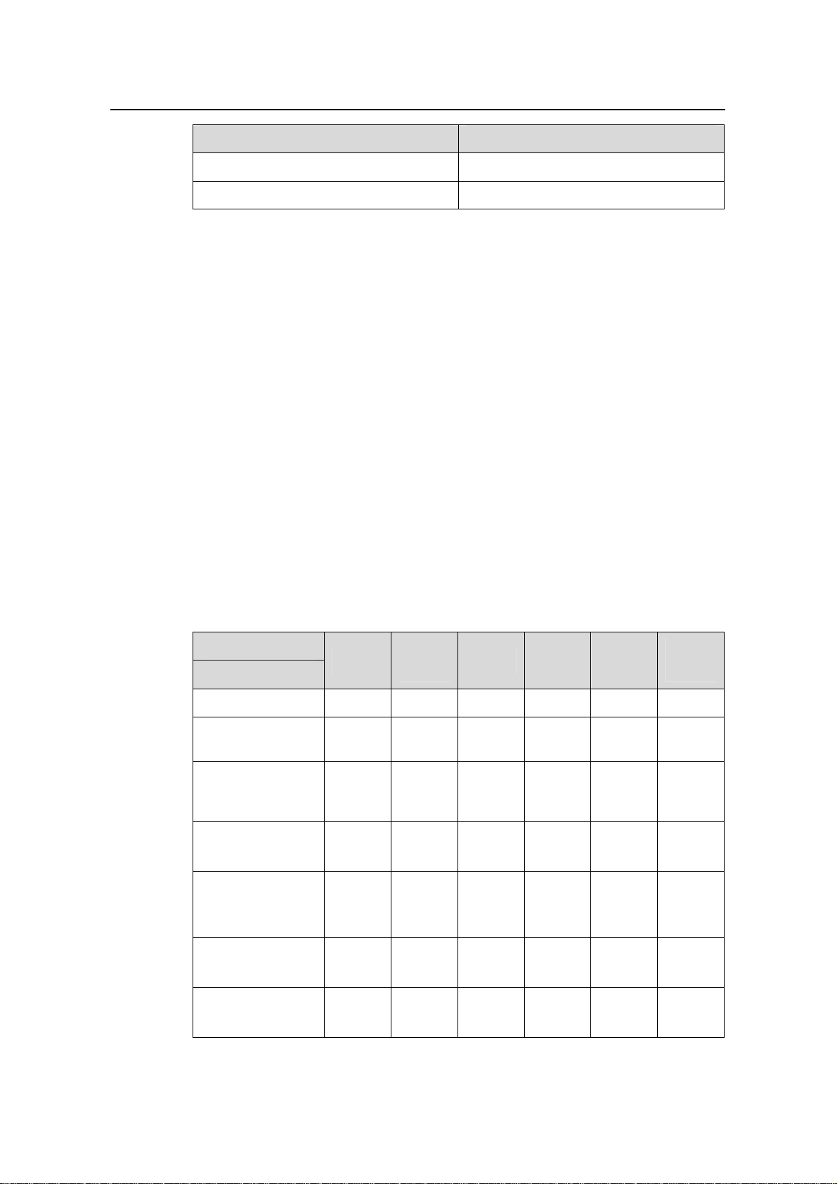
Table 1-1 Dimensions of the S7500E series
Model Slot direction Number of slots Number of SRPU slots
S7502E Horizontal 4 2 half-sized slots
S7503E-S Horizontal 3 1
S7503E Horizontal 5 2
S7506E Horizontal 8 2
S7510E Horizontal 12 2
S7506E-V Vertical 8 2
Table 1-1.
1.2 Physical Description of the S7500E Series
1.2.1 Chassis and Slots
The integrated chassis of the S7500E series consists of a card are a, a fan area, and a
power supply area.
Table 1-2 Dimensions of the S7500E series
Model Dimensions (H × W × D)
S7502E 175 × 436 × 420 mm (6.89 × 17.17 × 16.54 in.)
S7503E-S 175 × 436 × 420 mm (6.89 × 17.17 × 16.54 in.)
S7503E 441 × 436 × 420 mm (17.36 × 17.17 × 16.54 in.)
S7506E 575 × 436 × 420 mm (22.64 × 17.17 × 16.54 in.)
S7510E 708 × 436 × 420 mm (27.87 × 17.17 × 16.54 in.)
1-1
Page 10
Installation Manual
H3C S7500E Series Ethernet Switches Chapter 1 Product Overview
Model Dimensions (H × W × D)
S7506E-V 930 × 436 × 420 mm (36.61 × 17.17 × 16.54 in.)
Note:
z The backplane, switching & routing processing unit (SRPU), power modules, and
fan tray are all required parts of the S7500E series.
z SRPUs and line processing units (LPUs) are distinguished by their edge colors.
SRPUs have pink edges while LPUs have purple edges. SRPUs must be inserted in
pink slots while LPUs must be inserted in purple slots.
z The power supply of the S7500E series can be AC or DC, depending on the actual
requirement. However, it is forbidden to insert different power modules into one
S7500E Ethernet switch.
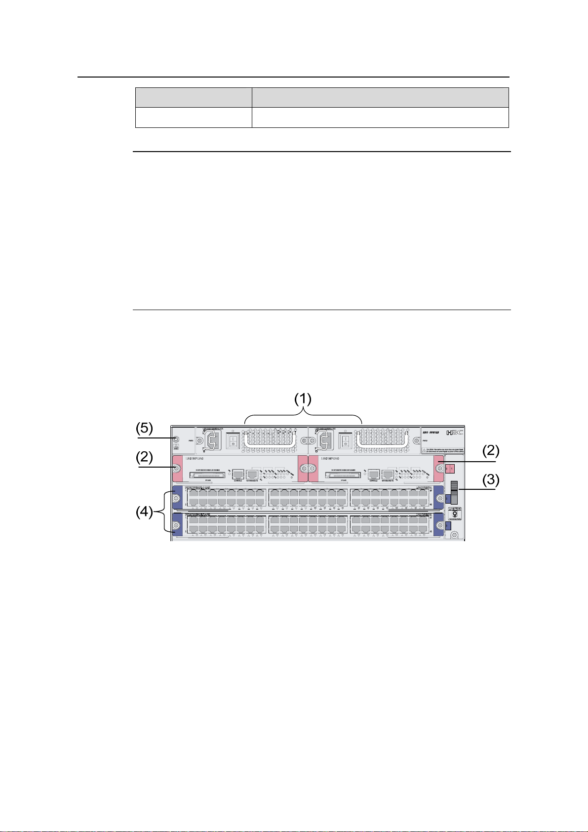
I. S7502E
Figure 1-1 shows the front panel of the S7502E.
(1) Power modules (2) SRPUs (in slot 0 and slot 1)
(3) Fan tray (4) LPUs (in slot 2 and slot 3)
(5) Jack for ESD-preventive wrist strap
Figure 1-1 Front panel of the S7502E
All modules of the S7502E are hot swappable.
z The S7502E has four horizontal slots. SRPUs are inserted into the upper two slo ts.
See callout (2) in
Figure 1-1. SRPUs are required and support active-standby
switchover. Different LPUs are inserted into the other two slots. See callout (4) in
Figure 1-1.
z The fan tray is installed on the right side of the chassis. See callout (3) in Figure
1-1.
1-2
Page 11
Installation Manual
H3C S7500E Series Ethernet Switches Chapter 1 Product Overview
z The two power modules, which sit in the upper part of the chassis provide 1+1
redundancy backup. See callout (1) in
Figure 1-1. You can select either AC power
supply or DC power supply.
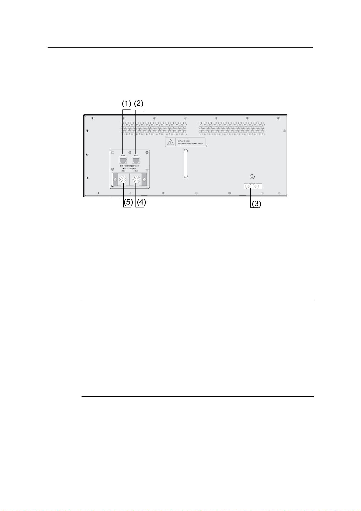
Figure 1-2 shows the rear panel of the S7502E.
(1) COM port for monitoring PoE (RS485) (2) COM port for monitoring PoE (RS232)
(3) Grounding screws
(5) Negative terminal (–) of external PoE
power supply (–46 V to –55 V)
(4) RTN terminal (+) of external PoE power
supply
Figure 1-2 Rear panel of the S7502E
There are two DC power input (PoE power supply input) terminals and two COM ports
(monitor ports) on the rear panel of the chassis.
Note:
z The S7500E se ries are Power over Ethernet (PoE ) capable, that is, they can supply
power to devices such as IP phones, wireless access points, and network cameras
connected to their Ethernet ports through twisted pair cables.
z For the S7502E and S7503E-S, the external PoE power supply is connected to the
PoE power supply input terminals on the rear panel, while for the other models of
the S7500E series, the external PoE power supply is connected to a power module.
For details, refer to section
PSR2800-ACV” on page 1-16.
VII. “
1.2.3 VI. “PSR1400-D” on page 1-15 and section 1.2.3
II. S7503E-S
Figure 1-3 shows the front panel of the S7503E-S.
1-3
Page 12
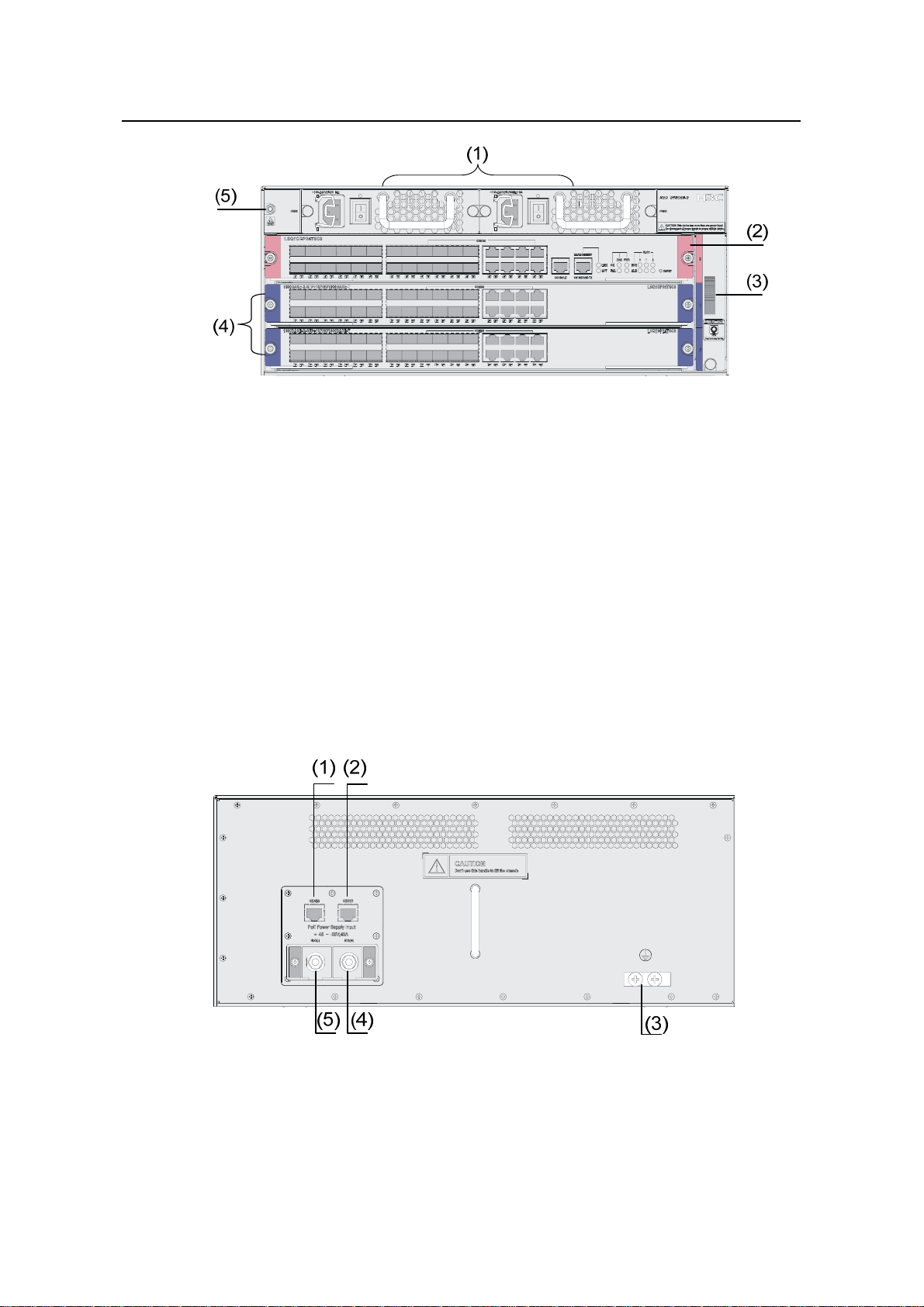
Installation Manual
H3C S7500E Series Ethernet Switches Chapter 1 Product Overview
(1) Power modules (2) SRPUs (in slot 0)
(3) Fan tray (4) LPUs (in slot 1 and slot 2)
(5) Jack for ESD-preventive wrist strap
Figure 1-3 Front panel of the S7503E-S
All modules of the S7503E-S are hot swappable.
z The S7503E-S has three horizontal slots. SRPUs are inserted into the upper slot.
See callout (2) in
LPUs are inserted into the other two slots. See callout (4) in
z The fan tray is installed on the right side of the chassis. See callout (3) in Figure
Figure 1-3. Dedicated S7503E-S SRPUs are required. Different
Figure 1-3.
1-3.
z The two power modules, which sit in the upper part of the chassis provide 1+1
redundancy backup. See callout (1) in
Figure 1-3. You can select either AC power
supply or DC power supply.
Figure 1-4 shows the rear panel of the S7503E-S.
(1) COM port for monitoring PoE (RS485) (2) COM port for monitoring PoE (RS232)
(3) Grounding screws
(5) Negative terminal (–) of external PoE
power supply (–46 V to –55 V)
(4) RTN terminal (+) of external PoE power
supply
Figure 1-4 Rear panel of the S7503E-S
1-4
Page 13
Installation Manual
H3C S7500E Series Ethernet Switches Chapter 1 Product Overview
There are two DC power input (PoE power supply input) terminals and two COM ports
(monitor ports) on the rear panel of the chassis.
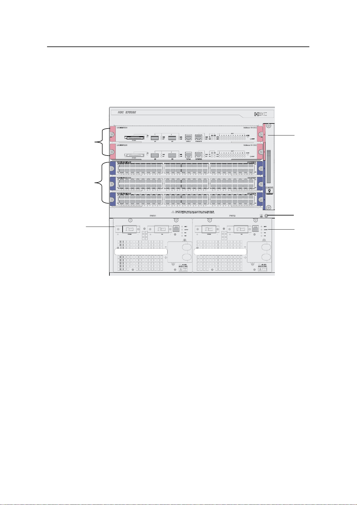
III. S7503E
Figure 1-5 shows the front panel of the S7503E.
(1)
(5)
(4)
(2)
(3)
(3)
(1) Fan tray (2) Jack for ESD-preventive wrist strap
(3) Power modules (4) LPUs (in slot 2 to slot 4)
(5) SRPUs (in slot 0 and slot 1)
Figure 1-5 Front panel of the S7503E
All the modules of the S7503E are hot swappable.
z The S7503E has five horizontal slots. SRPUs are inserted into the upper two slots
(see callout (5) in
Figure 1-5). SRPUs are required and support active-standby
switchover. Different LPUs are inserted into the other three slots (see callout (4) in
Figure 1-5).
z The fan tray is installed on the right side of the chassis (see callout (1) in Figure
1-5).
z The two power modules, which sit in the lower part of the chassis (se e callout (3) in
Figure 1-5), provide 1+1 redundancy backup. You can select either AC power
supply or DC power supply.
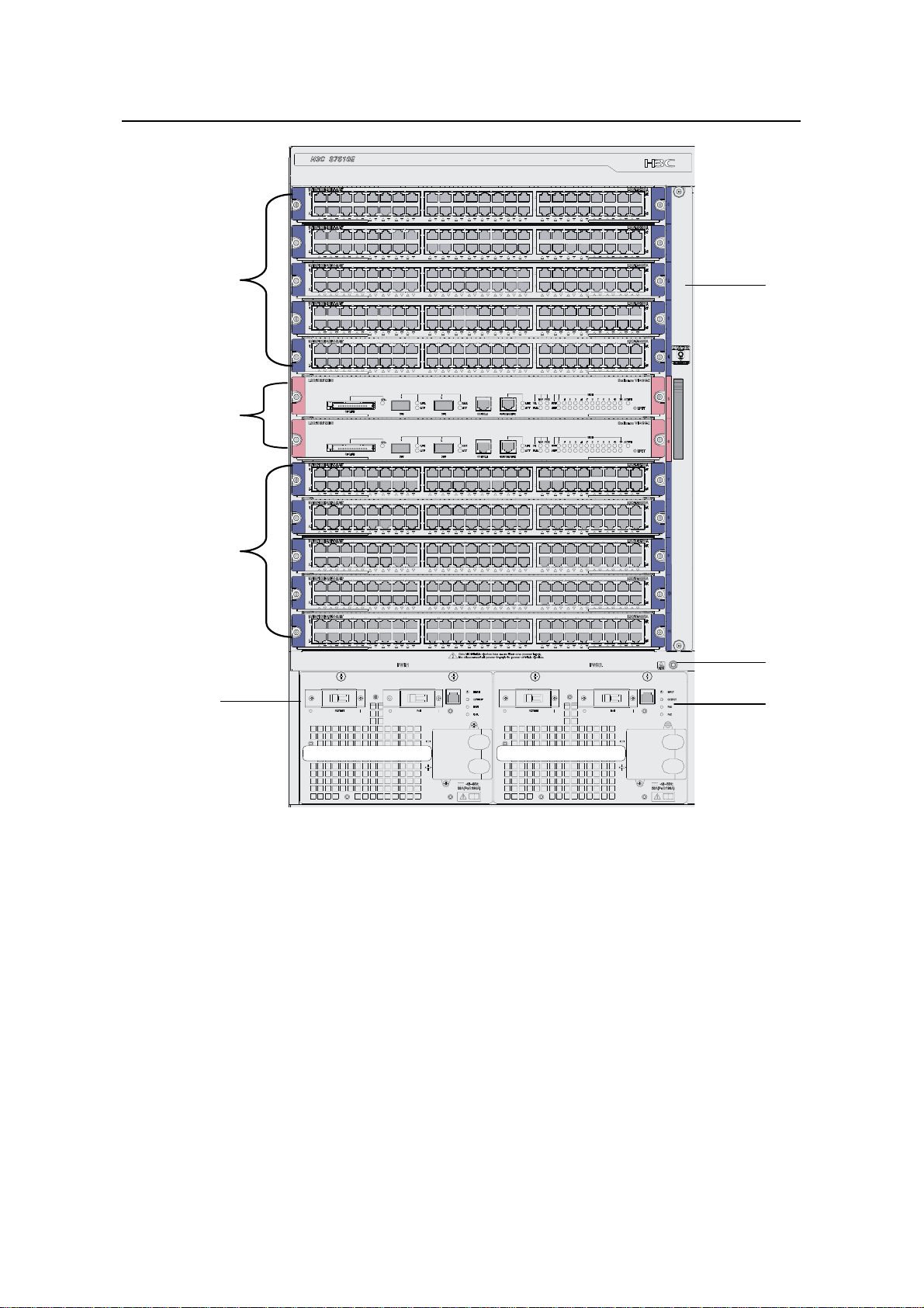
IV. S7506E
Figure 1-6 shows the front panel of the S7506E.
1-5
Page 14
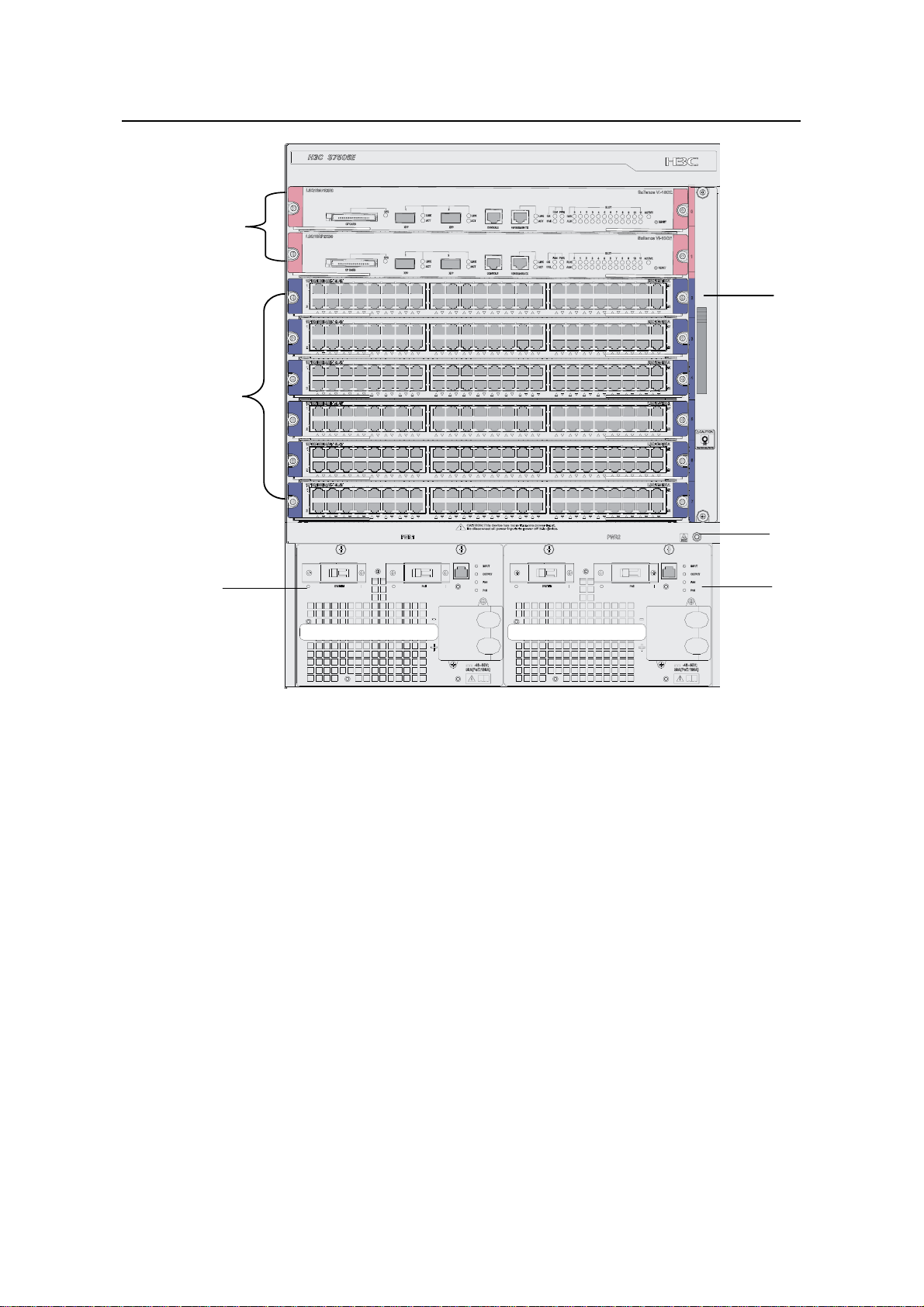
Installation Manual
H3C S7500E Series Ethernet Switches Chapter 1 Product Overview
(5)
(1)
(4)
(2)
(3)
(3)
(1) Fan tray (2) Jack for ESD-preventive wrist strap
(3) Power module (4) LPUs (in slot 2 to slot 7)
(5) SRPUs (in slot 0 and slot 1)
Figure 1-6 Front panel of the S7506E
All the modules of the S7506E are hot swappable.
z The S7506E has eight horizontal slots. SRPUs are inserted in the upper two slots
(see callout (5) in
Figure 1-6). SRPUs are required and support active-standby
switchover. Different LPUs are inserted into the other six slots (see callout (4) in
Figure 1-6).
z The fan tray is installed on the right side of the chassis (see callout (1) Figure 1-6).
z The two power modules, which sit in the lower part of the chassis (se e callout (3) in
Figure 1-6), provide 1+1 redundancy backup. You can select either AC power
supply or DC power supply.
V. S7510E
Figure 1-7 shows the front panel of the S7510E.
1-6
Page 15
Installation Manual
H3C S7500E Series Ethernet Switches Chapter 1 Product Overview
(4)
(5)
(4)
(3)
(1)
(2)
(3)
(1) Fan tray (2) Jack for ESD-preventive wrist strap
(3) Power module (4) LPUs (in slot 0 to slot 4 and slot 7 to slot 11)
(5) SRPUs (in slot 5 and slot 6)
Figure 1-7 Front panel of the S7510E
All the modules of the S7510E are hot swappable.
z The S7510E has twelve horizontal slots. SRPUs are inserted in the middle two
slots (see callout (5) in
Figure 1-7). SRPUs are required and support
active-standby switchover. Different LPUs are inserted in the other ten slots (see
callout (4) in
z The fan tray is installed on the right side of the chassis (see callout (1) in Figure
Figure 1-7).
1-7).
z The two power modules, which sit in the lower part of the chassis (se e callout (3) in
Figure 1-7), provide 1+1 redundancy backup. You can select either AC power
supply or DC power supply.
1-7
Page 16
Installation Manual
H3C S7500E Series Ethernet Switches Chapter 1 Product Overview
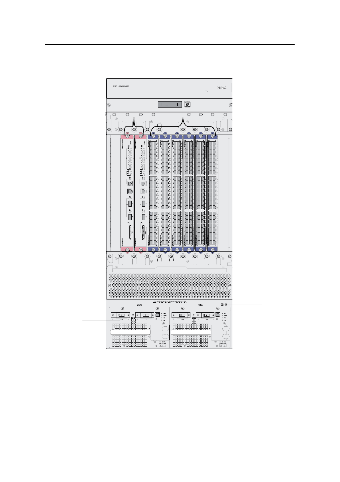
VI. S7506E-V
Figure 1-8 shows the front panel of the S7506E-V.
(1)
(6)
(2)
(5)
(3)
(4)
(1) Fan tray (2) LPUs (in slot 2 to slot 7)
(3) Jack for ESD-preventive wrist strap (4) Power module
(5) Air filter (6) SRPUs (in slot 0 and slot 1)
Figure 1-8 Front panel of the S7506E-V
All the modules of the switch are hot swappable.
z The S7506E-V switch has eight vertical slots. SRPUs are inserted in the left two
slots (see callout (5) in
Figure 1-8). SRPUs are required and support
(4)
1-8
Page 17
Installation Manual
H3C S7500E Series Ethernet Switches Chapter 1 Product Overview
active-standby switchover. Different LPUs are inserted in the other six slots (see
callout (2) in
z The fan tray is installed above the SRPUs and LPUs (see callout (1) in Figure 1-8)
Figure 1-8).
and the air flows up from the bottom.
z The two power modules, which sit in the lower part of the chassis (se e callout (3) in
Figure 1-8), provide 1+1 redundancy backup. You can select either AC power
supply or DC power supply.
1.2.2 Backplane
The backplane in the integrated chassis of the S7500E series implements high-speed
data exchange as well as management & control signal exchange bet ween SRPUs and
LPUs.
The backplane mainly provides the following functions:
z Interconnection between cards
z Card hot-swapping
z Automatic slot recognition
z Automatic chassis type recognition
z Distributed power supply to the system. The S7506E-V has two backplanes:
signal backplane and power supply backplane. The power supply backplane is
connected to the power modules and is also connected to the signal backplane
with an internal cable.
z Connection of the signal cable that monitors the fan tray and power supply
1.2.3 Power Supply System
The S7500E series support a variety of power modules, as listed in Table 1-3.
Table 1-3 Power module models of the S7500E series
Model Height
PSR320-A 1 U AC No
PSR320-D 1 U DC No
PSR650-A 1 U AC No
PSR650-D 1 U DC No
PSR1400-A 3 U AC No
PSR1400-D 3 U DC No
PSR2800-ACV 3 U AC No
Power input
mode (AC/DC)
Support PoE
power (Yes/No)
1-9
Page 18
Installation Manual
H3C S7500E Series Ethernet Switches Chapter 1 Product Overview
Table 1-4 Features of power modules
Feature Description
Support input under-voltage protection, output
Protection functions
over-voltage protection, short-circuit protection,
over-current protection, and overheat protection
1+1 hot backup support Support 1 + 1 hot backup and current sharing
Hot swap support
Support hot swap with the power switch turned off
while the device is in operation
Typically, the S7502E and the S7503E-S use 1U power modules, while the other
models of the S7500E series use 3U power modules.
The S7500E series support a large variety of card types, and system power
consumption of a switch varies with different types of cards in use. You can choose an
appropriate power module model for your switch based on its system power
consumption.
H3C has designed a power module adapter, PWR-SPA, to allow flexible power module
options to suit different system power consumption characteristics.
You can use PSR650 power modules in combination with PWR-SPA power module
adapters to power a switch with system power consumption lower than 650 W, instead
of using heavy-duty power modules like the PSR1400 or PSR2800.
The system power consumption of a switch is determined by its SRPUs, LPUs, and fan
tray. Specifically, the system power consumption of a switch is equal to the power
consumption of its SRPUs, LPUs, and fan tray put together.
For how to install power modules and power module adapters, refer to section 5.2
"Removing and Installing a Power Module."
Table 1-5 Compatibility matrix between power modules and switch chasses
Chassis
(right)
Power
S7502E
S7503E-
S
S7503E S7506E
S7506E-V S7510
E
module
(below)
PSR320-A Y1 Y1 N N N N
PSR320-D Y1 Y1 N N N N
PSR650-A Y1 Y1 Y2 Y2 Y2 N
PSR650-D Y1 Y1 Y2 Y2 Y2 N
PSR1400-A N N Y1 Y1 Y1 Y1
PSR1400-D N N Y1 Y1 Y1 Y1
1-10
Page 19
Installation Manual
H3C S7500E Series Ethernet Switches Chapter 1 Product Overview
Chassis
(right)
Power
S7502E
S7503E-
S
S7503E S7506E
S7506E-V S7510
E
module
(below)
PSR2800-AC
V
N N Y1 Y1 Y1 Y1
Note:
z Y1 means that the power module directly fits the chassis.
z Y2 means that you need to insert a power module adapter into the chassis and then
inserting the power module into the power module adapter.
z N means that the power module cannot be used in the chassis.
z Do not use di fferent types of power modules in the same device.
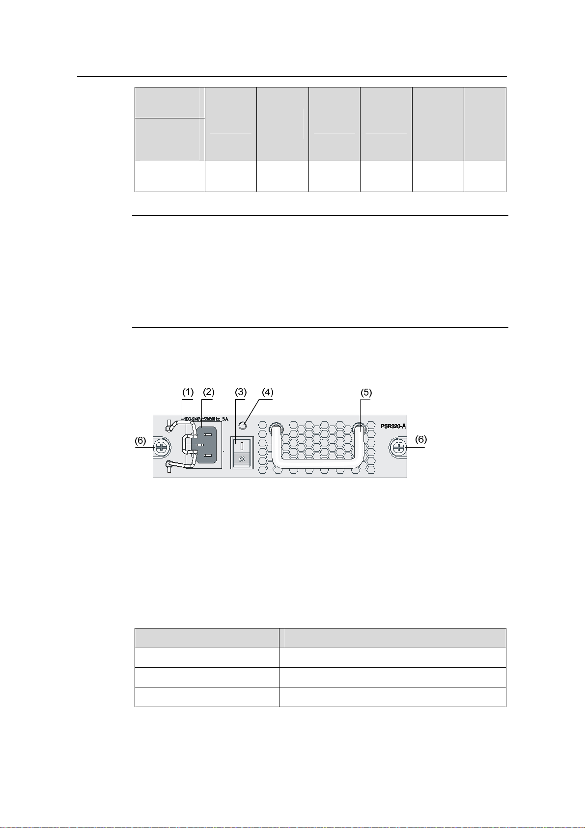
I. PSR320-A
(1) Power cable retainer (2) AC power socket
(3) Power switch (4) Power LED
(5) Power module handle (6) Captive screws
Figure 1-9 PSR320-A power module
As shown in the figure, above the power switch is the power LED. If the power LED is
green, the power supply operates normally. If the LED is red, the power supply is
abnormal.
Table 1-6 Technical specifications of the PSR320-A power module
Item Specifications
Rated voltage range 100 VAC to 240 VAC; 50 Hz or 60 Hz
Maximum output power 300 W
Dimensions (H × W × D) 40 × 140 × 350 mm (1.57 × 5.51 × 13.78 in.)
1-11
Page 20
Installation Manual
H3C S7500E Series Ethernet Switches Chapter 1 Product Overview
Note:
The PSR320-A uses a 10-A AC power cable.
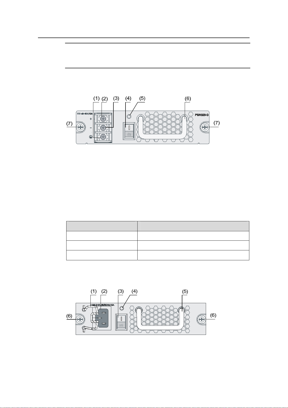
II. PSR320-D
(1) Grounding screws (2) RTN terminal (+) of DC input
(3) Negative terminal (–) of DC input (–48 V to –60 V) (4) Power switch
(5) Power LED (6) Power module handle
(7) Captive screws
Figure 1-10 PSR320-D power module
As shown in the figure, above the power switch is the power LED. If the power LED is
green, the power supply operates normally. If the power LED is red, the power supply is
abnormal.
Table 1-7 Technical specifications of the PSR320-D power module
Item Specifications
Rated voltage range –48 VDC to –60 VDC
Maximum output power 300 W
Dimensions (H × W × D) 40 × 140 × 350 mm (1.57 × 5.51 × 13.78 in.)
III. PSR650-A
(1) Power cable retainer (2) AC power socket
(3) Power switch (4) Power LED
(5) Power module handle (6) Captive screws
Figure 1-11 PSR650-A power module
1-12
Page 21
Installation Manual
H3C S7500E Series Ethernet Switches Chapter 1 Product Overview
Above the power switch is the power LED. If the power LED is gree n, the power supply
operates normally. If the LED is red, the power supply is abnormal.
Table 1-8 Technical specifications of the PSR650-A power module
Item Specifications
Rated voltage range 100 VAC to 240 VAC; 50 Hz or 60 Hz
Maximum output power 650 W
Dimensions (H × W × D) 40 × 140 × 350 mm (1.57 × 5.51 × 13.78 in.)
Note:
The PSR650-A uses a 10 A AC power cable.
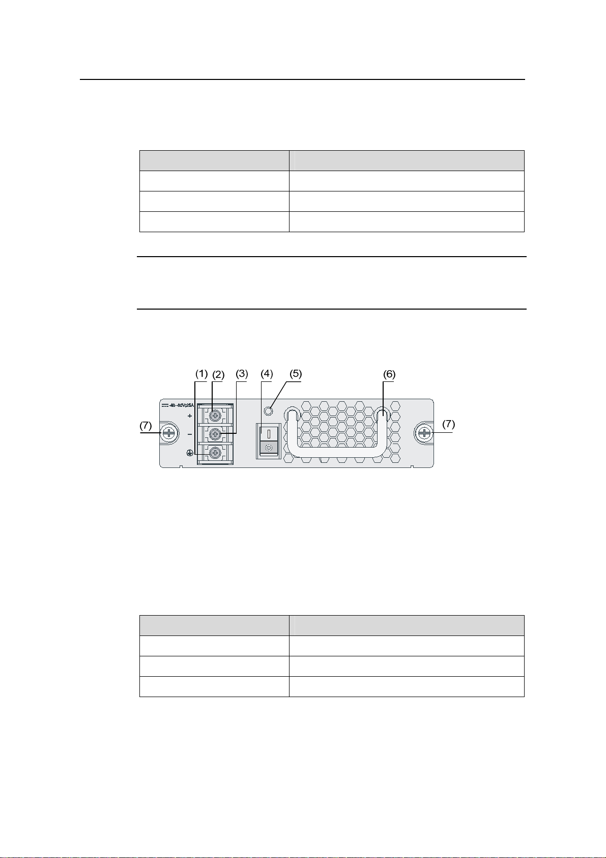
IV. PSR650-D
(1) Grounding screw (2) RTN terminal (+) of DC input
(3) Negative terminal (–) of DC input (–48 V to –60 V) (4) Power switch
(5) Power LED (6) Power module handle
(7) Captive screws
Figure 1-12 PSR650-D power module
Above the power switch is the power LED. If the power LED is gree n, the power supply
operates normally. If the power LED is red, the power supply is abnormal.
Table 1-9 Technical specifications of the PSR650-D power module
Item Specifications
Rated voltage range –48 VDC to –60 VDC
Maximum output power 650 W
Dimensions (H × W × D) 40 × 140 × 350 mm (1.57 × 5.51 × 13.78 in.)
1-13
Page 22
Installation Manual
H3C S7500E Series Ethernet Switches Chapter 1 Product Overview
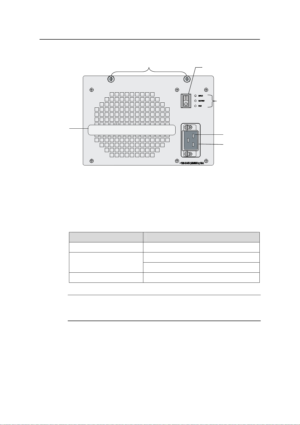
V. PSR1400-A
(1)
(2)
(3)
(6)
(4)
(5)
(1) Captive screws (2) Power switch
(3) Power LEDs (4) AC power socket
(5) Power cable retainer (6) Power module handle
Figure 1-13 PSR1400-A power module
On the right of the switch are the input LED, output LED, and fan LED. For their colo rs
and descriptions, refer to section 7.2.3 “Troubleshooti ng PSR1400-A.”
Table 1-10 Technical specifications of the PSR650-A power module
Item Specifications
Rated voltage range 100 VAC to 240 VAC; 50 Hz or 60 Hz
1150 W (110 V)
Maximum output power
1400 W (220 V)
Dimensions (H × W × D) 128 × 196 × 380 mm (5.04 × 7.72 × 14.96 in.)
Note:
The PSR1400-A uses a 16 A AC power cable.
1-14
Page 23
Installation Manual
H3C S7500E Series Ethernet Switches Chapter 1 Product Overview
VI. PSR1400-D
(1)
(2)
(8)
(7)
(3)
(4)
(6)
(5)
(1) Captive screws (2) COM port for monitoring PoE
(3) Power LEDs (4) Negative terminal (–) of DC input (–48 V to –60 V)
(5) RTN terminal (+) of DC input (6) Power module handle
(7) System power switch (8) PoE power switch
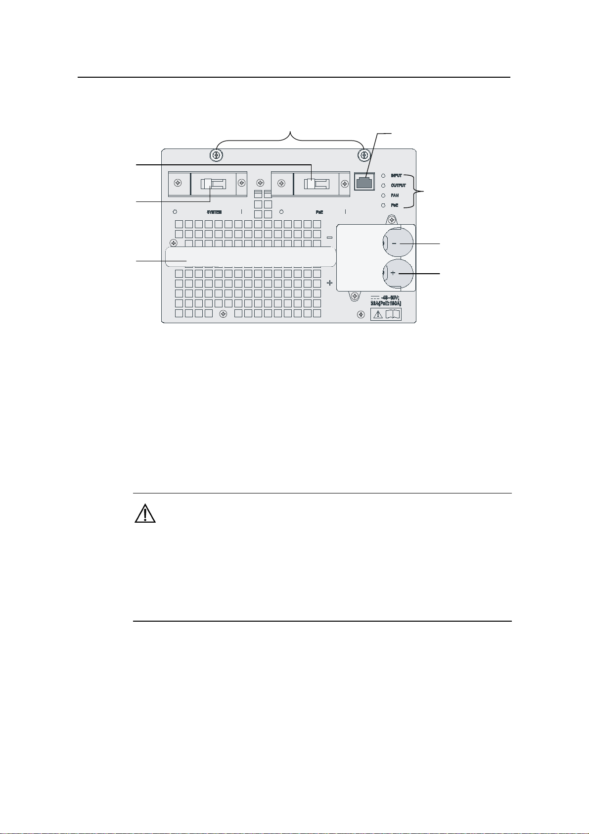
Figure 1-14 PSR1400-D power module
The PSR1400-D power module provides system power and PoE power. The switch
marked “SYSTEM” is used to control the system power, and the other marked “PoE” is
used to control the PoE power. The RJ-45 port (RS485) on the right of the PoE power
switch is the COM port for monitoring PoE.
Caution:
z If power to the PSR1400-D power module is switch controlled, make sure that the
negative input of the power module is disconnected when disconnecting power to
the power module.
z Keep the PoE power swit ch in the off position unless the device needs to offer PoE
supply and is equipped with appropriate PoE-capable cards.
On the right of the panel are the input LED, output LED, fan LED and PoE LED. For
their colors and descriptions, refer to section 7.2.4 “Troubleshooting PSR1400-D.”
1-15
Page 24
Installation Manual
H3C S7500E Series Ethernet Switches Chapter 1 Product Overview
Table 1-11 Technical specifications of the PSR1400-D DC power module
Item Specifications
Rated voltage range –48 VDC to –60 VDC
Maximum system output power 1400 W
Maximum PoE output power 6720 W
Dimensions (H × W × D) 128 × 196 × 380 mm (5.04 × 7.72 × 14.96 in.)
VII. PSR2800-ACV
(1)
(2)
(3)
(4)
(9)
(5)
(6)
(7)
(8)
(1) Captive screws (2) System power socket
(3) Power cable retainer (4) System power switch
(5) Power LEDs (6) PoE power socket
(7) Power cable retainer (8) PoE power switch
(9) Power module handle
Figure 1-15 PSR2800-ACV power module
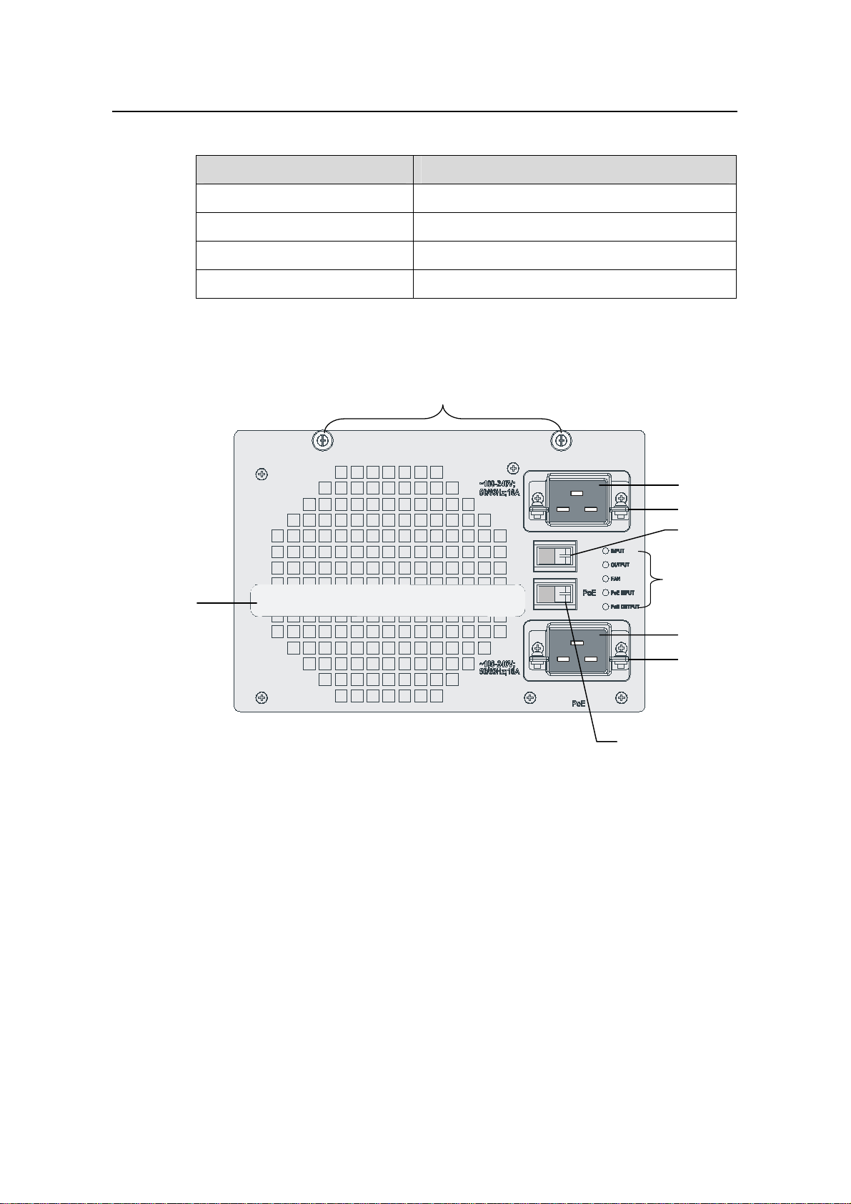
The PSR2800-ACV power module provides system power and PoE power. In
1-15, the switch indicated by (4) is used to control the power input of the whole system
and the socket indicated by (2) is used for system power input, while the switch
indicated by (8) is used to control the PoE power and the socket indicated by (6) i s used
for PoE power input.
Figure
1-16
Page 25
Installation Manual
H3C S7500E Series Ethernet Switches Chapter 1 Product Overview
Caution:
Keep the PoE power switch in the off position unless the device needs to offer PoE
supply and is equipped with appropriate PoE-capable cards.
On the right of the panel are the input LED, output LED, fan LED, PoE input LED, and
PoE output LED. For the descriptions of these LEDs, refer to section 7.2.5
“Troubleshooting PSR2800-ACV.”
Table 1-12 Technical specifications of the PSR2800-ACV power module
Specifications Value or ran ge
Rated voltage range 100 VAC to 240 VAC, 50 Hz or 60 Hz
Maximum system output power
1150 W (110 V)
1400 W (220 V)
1150 W (110 V)
Maximum PoE output power
1400 W (220 V)
Physical dimensions (H × W × D) 128 × 196 × 380 mm (5.04 × 7.72 × 14.96 in.)
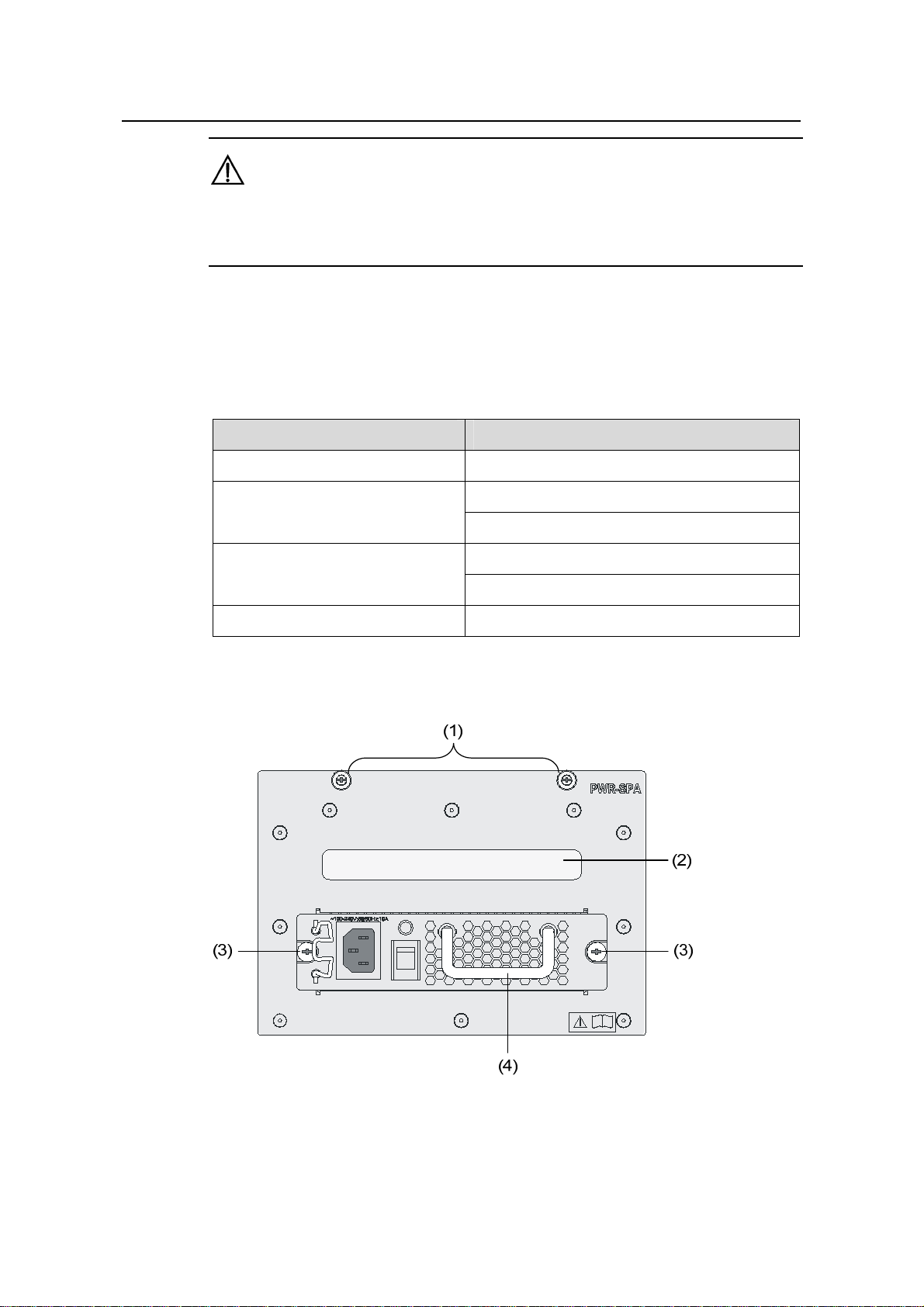
VIII. PWR-SPA
(1) Captive screw on the power module adapter (2) Power module adapter ha ndle
(3) Captive screw on the PSR650-A power module (4) PSR650-A power module handle
Figure 1-16 Schematic view of the power module adapter with a PSR650-A installed
1-17
Page 26
Installation Manual
H3C S7500E Series Ethernet Switches Chapter 1 Product Overview
When the system power consumption of a switch (S7503E, S7506E, S7506E-V, or
S7510E) is less than the maximum output power of a 1U power module, you can first
insert the PWR-SPA power module adapters into the switch, and then insert 1U power
modules into the power module adapters. By doing so, you can use the 1U-high power
modules to power the switch.
A PWR-SPA power module adapter has the same physical dimensions with a 3U power
module.
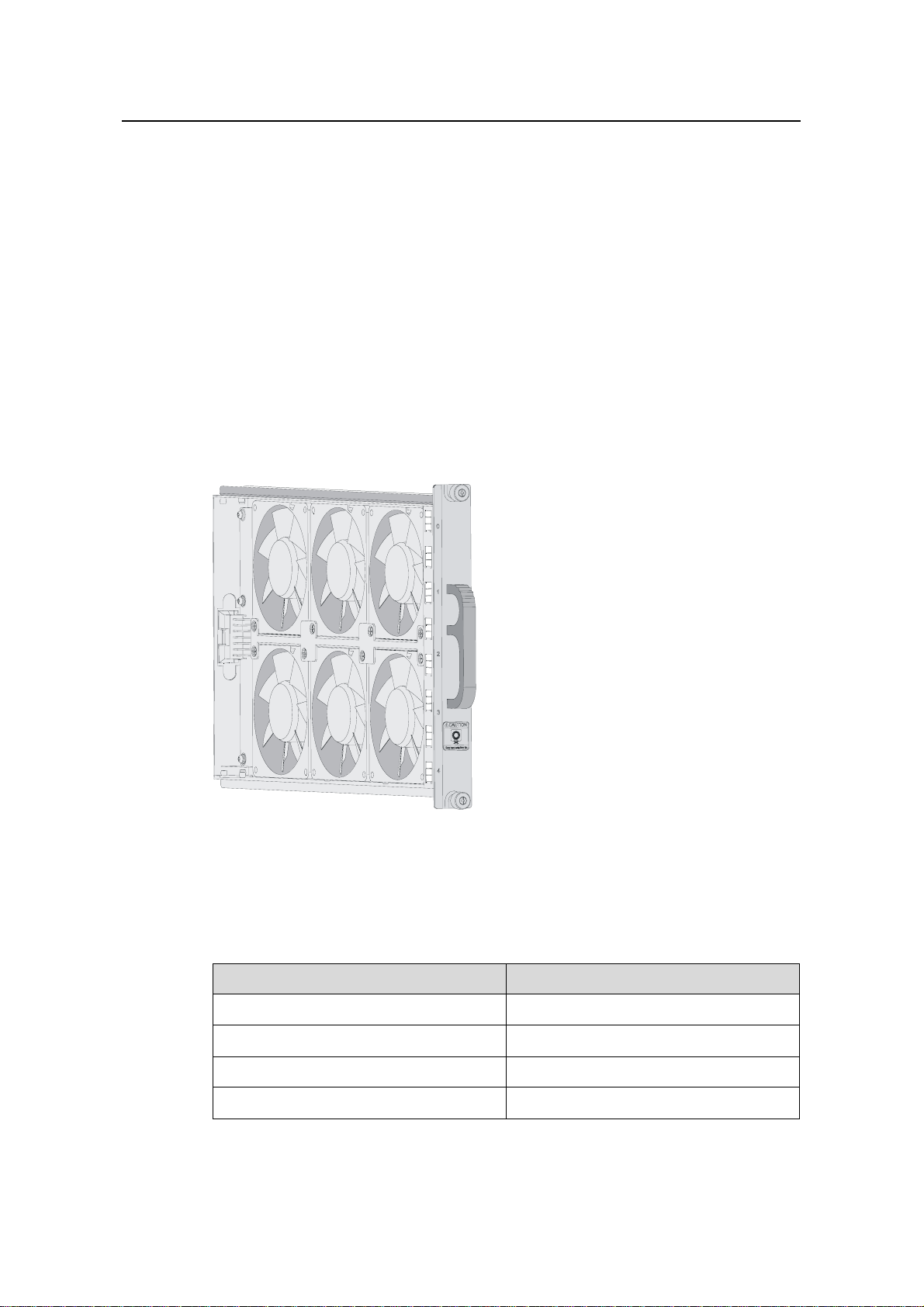
1.2.4 Fan Tray
The S7502E, S7503E-S, S7503E, S7506E and S7510E switches provide chassis for
horizontal cards. The fan tray is installed on the right side of the front of the chassis.
The S7506E-V switch provides chassis for vertical ca rds. The fan tray is installed on the
upper of the front of the chassis.
Figure 1-17 Fan tray (for the S7503E)
The power consumption of the fan trays for the S7500E series varies with fan tray
models.
Table 1-13 Power consumption of the fan trays for the S7500E series
Model Power consumption (W)
S7502E fan tray 20
S7503E-S fan tray 20
S7503E fan tray 30
S7506E fan tray 45
1-18
Page 27
Installation Manual
H3C S7500E Series Ethernet Switches Chapter 1 Product Overview
Model Power consumption (W)
S7510E fan tray 50
S7506E-V fan tray 50
1.2.5 Air Filter
Over a long period of time, dust may block the air filter at the air intake vent of the
S7500E series. As a result, the heat dissipation of the system may be affected. You are
recommended to clean the air filter every three months. Air filters are optional
accessories.
Since the air flows up from the bottom, air filters for the S7506E-V, different from those
for the other models, are installed on the front and rear sides near the bottom of the
chassis.
1.3 SRPUs
1.3.1 SRPU Types
For the S7500E series, SRPUs are the core in the control and management plane and
switching fabric. The S7500E series provide eight types of SRPUs.
Table 1-14 SRPUs and their suitable chassis
Chassis (right)
Engine (below)
LSQ1MPUA0 Yes No No No No No
LSQ1CGP24TSC
0
LSQ1SRP2XB0
(Salience
VI-10GE)
LSQ1SRPB0
(Salience VI)
LSQ1SRP1CB0
(Salience
VI-Turbo)
S7502E
No Yes No No No No
No No Yes Yes Yes Yes
No No Yes Yes Yes Yes
No No Yes Yes Yes Yes
S7503E
-S
S7503E S7506E S7510E
S7506E
-V
LSQ1MPUB0
(Salience VI-Lite)
LSQ1SRPD0
(Salience VI-Plus)
No No Yes Yes Yes Yes
No No Yes Yes Yes Yes
1-19
Page 28
Installation Manual
H3C S7500E Series Ethernet Switches Chapter 1 Product Overview
Chassis (right)
S7502E
Engine (below)
S7503E
-S
S7503E S7506E S7510E
S7506E
-V
LSQ1SRP12GB0
(Salience VI-GE)
Note:
The S7500E series, except the S7503E-S, are a dual-SRPU system. The SRPUs in a
chassis must be of the same type.
1.3.2 LSQ1MPUA0 SRPU
I. Applicable model
S7502E
II. Technical specifications
Table 1-15 Technical specifications of the LSQ1MPUA0
Item Specifications
No No Yes Yes Yes Yes
CPU MIPS64, 600 MHz
Boot ROM 512 KB
Flash memory 64 MB
DDR SDRAM 512 MB
Dimensions (H × W × D) 45 × 199 × 355 mm (1.77 × 7.83 × 13.98 in.)
z One compact flash (CF) card interface
z One console port, used for local or remote
Interfaces
configuration and management of the switch
through a dialup configuration
z One 10/100Base-TX management Ethernet port
Power consumption 10 W to 15 W
Note:
The dimensions of the S7500E series are expressed in the form of H × W × D, where
H: Height of the front panel of the card.
W: Width of the part inserted into the chassis, instead of that of the front panel.
D: Depth from the front panel to the other end, excluding the length of the handle.
1-20
Page 29
Installation Manual
H3C S7500E Series Ethernet Switches Chapter 1 Product Overview
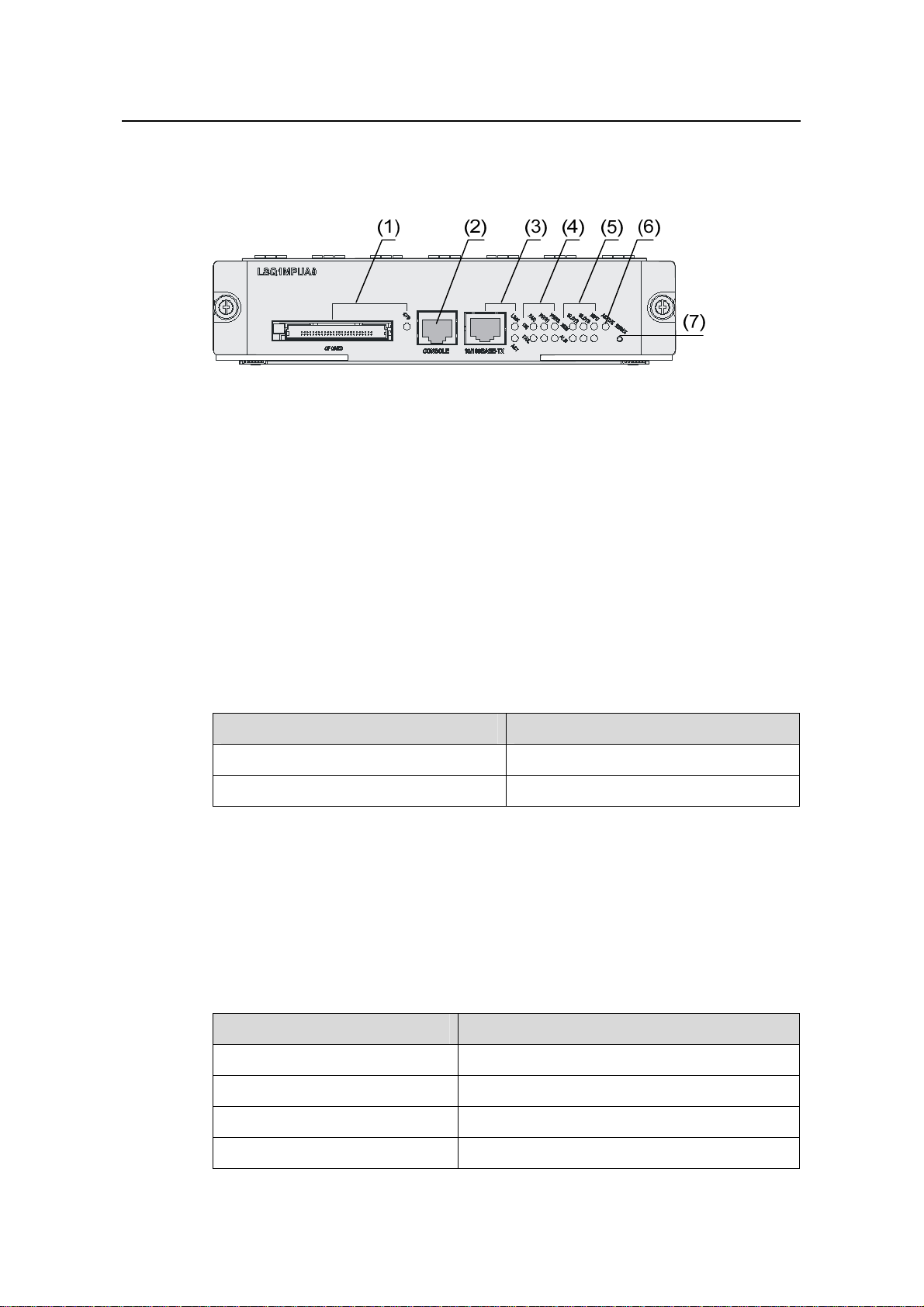
III. Panel and LEDs
Figure 1-18 shows the front panel of the LSQ1MPUA0.
(1) CF card interface and CFS LED (2) Console port
(3) 10/100Base-TX Ethernet port for management and LEDs
(4) Power and fan tray status LEDs (5) LPU status LEDs
(6) ACTIVE LED of LSQ1MPUA0 (7) RESET button
Figure 1-18 Front panel of the LSQ1MPUA0
IV. On-board interfaces
z CF card slot
The CF card slot can accommodate a standard CF card (Type I or Type II), where you
can store host software and logs, and thus u pgrade software conveniently. The CF card
is hot swappable.
Table 1-16 describes the CFS LED on the right of the CF card.
Table 1-16 Description of the CFS LED
Status Description
OFF No CF card is in position.
ON The CF card is in position.
z Console port
Using an RJ-45 connector, the console port can be connected through a regular
asynchronous serial cable directly to a computer for system debugging, configuration,
maintenance, management, and host software loading, or to a modem for remote
system debugging, configuration, maintenance and management.
Table 1-17 Specifications of the console port
Item Specifications
Connector type RJ-45
Number of connectors 1
Interface standard Asynchronous EIA/TIA-232
Baud rate 115,200 bps (defaulting to 9,600 bps)
1-21
Page 30
Installation Manual
H3C S7500E Series Ethernet Switches Chapter 1 Product Overview
Item Specifications
Transmission distance 15 m (49.21 ft.)
z It can be connected to an ASCII terminal.
Functions
z It can be connecte d to a serial port of a local
or remote (through a pair of modems) PC
running terminal emulation program.
z 10/100Base-TX Ethernet port for management
Using an RJ-45 connector, the 10/100Base-TX management Ethernet port can be
connected to a local PC for switch program loading and switch debugging, or
connected to a remote NMS for remote management.
Table 1-18 Specifications of the 10/100Base-TX Ethernet port
Item Specifications
Connector type RJ-45
Number of connectors 1
Interface speed 10/100 Mbps, half/full duplex
Cable medium and maximum
transmission distance
Function
Category-5 twisted pair, with a maximum
transmission distance of 100 m (328.08 ft.)
Host software & Boot ROM upgrade and
network management
T able 1-1 9 describes the LED status of the 10/10 0Base-TX management Ethernet port.
Table 1-19 Description of the status LEDs of the 10/100Base-TX management
Ethernet port
LED Description
LINK
ACT
z OFF: No link is present.
z ON: A link is present.
z OFF: No data is being transmitted or received.
z Blinking: Data is being transmitted or received.
V. System LEDs
z System status LEDs
The LEDs on the card panel indicate the statuses of the power modules, fan tray, two
LPUs, and LSQ1MPUA0 itself.
z Power status LEDs
PWR1 and PWR2: The LEDs show the statu s of the two po wer modules (AC or DC).
1-22
Page 31

Installation Manual
H3C S7500E Series Ethernet Switches Chapter 1 Product Overview
Table 1-20 Description of the power status LEDs
LED Description
OK
ON: The power module works normally.
OFF: The power module is faulty or out of position.
ON: The power module is faulty, or there is no power input to the power
FAIL
module, or the power switch is turned off.
OFF: The power module is operational or out of position.
z Fan status LEDs
FAN: The LEDs show the status of the fan tray.
Table 1-21 Description of the fan status LEDs
LED Description
OK
FAIL
z ON: The fans operate normally.
z OFF: The fans are faulty or out of position.
z ON: The fans are faulty or out of position.
z OFF: The fans operate normally.
z LPU status LEDs (SLOT2, SLOT3, MPU)
SLOT2 and SLOT3: The LEDs show the status of the LPUs in slot 2 and slot 3.
MPU: The LEDs show the status of the LSQ1MPUA0 itself.
Table 1-22 Description of LPU status LEDs
LED Description
RUN
ALM
z ON/OFF: The LPU is faulty or out of position.
z Blinking: The LPU is operating normally.
z OFF: The LP U is operational or out of position.
z ON: The LP U is faulty.
Note:
If the RUN LED flashes at a high frequency, the card is in the startup process, but is not
yet operational. At system startup, the ALM LED will be ON for a while but it does not
mean that the card is faulty.
z ACTIVE LED
The ACTIVE LED shows the active/standby status of the LSQ1MPUA0. If the ACTIVE
LED is ON, the LSQ1MPUA0 is active; if OFF, the LSQ1MPUA0 is standby .
1-23
Page 32

Installation Manual
H3C S7500E Series Ethernet Switches Chapter 1 Product Overview
VI. RESET button
A reset button is provided on the LSQ1MPUA0 for you to reset the card when
necessary.
1.3.3 Dedicated S7503E-S SRPU-LSQ1CGP24TSC0
I. Applicable model
S7503E-S
II. Technical specifications
Table 1-23 Technical specifications of the LSQ1CGP24TSC0
Item Specifications
CPU MIPS64, 400 MHz
Boot ROM 512 KB
Flash memory 64 MB
DDR SDRAM 512 MB
Dimensions (H × W × D) 45 × 377 × 355 mm (1.77 × 14.84 × 13.98 in.)
z Twenty-four
1000Base-X-SFP/100Base-FX-SFP ports, eight
of which can form eight Combo ports with the
eight 10/100/1000Base-T GE ports
Ports
z One console port, used for local or remote
configuration and management of the switch
through a dialup connection
z One 10/100Base-TX port for management and
upgrade
Power consumption 25 W to 45 W
III. Panel and LEDs
Table 1-19 shows the front panel of the LSQ1CGP24TSC0.
(1)
(2)
(3)
(4)
(5)
(6)
(1) GE/FE SFP optical ports (2) Combo ports
(3) Console port
(5) Power and fan tray status LEDs (6) LPU status LEDs
(7) RESET button
(4) 10/100Base-TX Ethernet management
port and its LEDs
Figure 1-19 Front panel of the LSQ1CGP24TSC0
1-24
(7)
Page 33

Installation Manual
H3C S7500E Series Ethernet Switches Chapter 1 Product Overview
IV. On-board interfaces
z Optical Ethernet ports and Combo ports
The LSQ1CGP24TSC0 provides twenty-four 1000Base-X-SFP/100Base-FX-SFP
ports and eight 10/100/1000Base-T GE port s. The eight GE port s and eight of th e SFP
ports can form eight Combo ports, each comprising a GE port and an SFP port.
Table 1-24 Specifications of the Ethernet ports
Item Specifications
Connector types
Number of connectors
Standards
Pluggable module type
z SFP
z RJ-45
z 24 SFP connectors
z 8 RJ-45 connectors
z IEEE 802.3-2005
z IEEE 802.1D-2004
z IEEE 802.1Q-2003
z IEEE 802.1X-2004
z Gigabit SFP module
z 100 Mbps SFP module
Refer to “Appendix A List of Pluggable Modules.”
Table 1-25 shows the pairings of the eight SFP ports and the eight GE ports for the
Combo interfaces.
Table 1-25 Pairings of the SFP ports and the GE ports for the Combo interfaces
1000Base-X-SFP/100Base-FX-SFP port
number
10/100/1000Base-T GE port
number
17 25
18 26
19 27
20 28
21 29
22 30
23 31
24 32
1-25
Page 34

Installation Manual
H3C S7500E Series Ethernet Switches Chapter 1 Product Overview
Note:
In a Combo port, only one of the 1000Base-X-SFP/100Base-FX-SFP port and the
10/100/1000Base-T GE port can be used at a time.
Each Ethernet port has a green LED.
Table 1-26 describes the LEDs.
Table 1-26 Description of the LED of each Ethernet port
LED Description
z OFF: No link is present.
LINK/ACT
z ON: A link is present.
z Blinking: Data is being transmitted or received.
z Console port
Using an RJ-45 connector, the console port can be connected through a regular
asynchronous serial cable directly to a computer for system debugging, configuration,
maintenance, management, and host software loading, or to a modem for remote
system debugging, configuration, maintenance and management.
Table 1-27 Specifications of the console port
Item Specifications
Connector type RJ-45
Number of connectors 1
Interface standard Asynchronous EIA/TIA-232
Baud rate 115,200 bps (defaulting to 9,600 bps)
Transmission distance 15 m (49.21 ft.)
z It can be connected to an ASCII terminal.
Functions
z It can be connected to the serial port of a
local or remote (through a pair of modems)
PC running terminal emulation program.
z 10/100Base-TX Ethernet port for management
Using an RJ-45 connector, the interface can be connected through a regular
asynchronous serial cable directly to a computer for switch program loading and switch
debugging, or to a remote NMS for remote management.
1-26
Page 35

Installation Manual
H3C S7500E Series Ethernet Switches Chapter 1 Product Overview
Table 1-28 Specifications of the 10/100Base-TX Ethernet port for management
Item Specifications
Connector type RJ-45
Number of connectors 1
Interface speed 10/100 Mbps, half/full duplex
Connecting cable and maximum
transmission distance
Function
Category-5 twisted pair, with a maximum
transmission distance of 100 m (328.08 ft.)
Used for switch software upgrade and
network management
Table 1-29 describes the status LED of the 10/100Base-TX Ethernet port.
Table 1-29 Description of the status LED of the 10/100Base-TX Ethernet port
LED Description
LINK
ACT
z OFF: No link is present.
z ON: A link is present.
z OFF: No data is being transmitted or received.
z Blinking: Data is being transmitted or received.
V. System LEDs
z System status LEDs
The LEDs on the card panel indicate the st atuses of the power modules, fan tray, LPUs,
and LSQ1CGP24TSC0 itself.
z Power status LEDs
PWR: The power status LEDs show the status of the power modules.
Table 1-30 Description of the power status LEDs
LED Description
OK
FAIL
z ON: The power modules operate normally.
z OFF: The power module is faulty or out of position.
z ON: At least one power m odule i s faulty or switched off.
z OFF: The power modules are operational or out of position.
z Fan status LEDs
FAN: The LEDs shows the status of the fan tray.
1-27
Page 36

Installation Manual
H3C S7500E Series Ethernet Switches Chapter 1 Product Overview
Table 1-31 Description of the fan status LEDs
LED Description
OK
FAIL
z ON: The fans operate normally.
z OFF: The fans are faulty or out of position.
z ON: The fans are faulty or out of position.
z OFF: The fans operate normally.
z LPU status LEDs (SLOT0, SLOT1, and SLOT2)
SLOT0, SLOT1, and SLOT2: The LPU status LEDs indicate the status of the LPUs
seated in these three slots.
Table 1-32 Description of LPU status LEDs
LED Description
RUN
ALM
z ON/OFF: The LPU is faulty or out of position.
z Blinking: The LPU is operating normally.
z OFF: The LP U is operational or out of position.
z ON: The LP U is faulty.
Note:
If the RUN LED flashes at a high frequency, the card is in the startup process, but is not
operational yet. At system startup, the ALM LED will be ON for a while, but it does not
mean that the card is faulty.
VI. RESET button
A reset button is provided on the LSQ1CGP24TSC0 for you to reset the card when
necessary.
1.3.4 Salience VI-10GE SRPU-LSQ1SRP2XB0
I. Applicable models
z S7503E
z S7506E
z S7510E
z S7506E-V
1-28
Page 37

Installation Manual
H3C S7500E Series Ethernet Switches Chapter 1 Product Overview
II. Technical specifications
Table 1-33 Technical specifications of the LSQ1SRP2XB0
Item Specifications
CPU MIPS64, 600 MHz
Boot ROM 512 KB
Flash memory 64 MB
DDR SDRAM 512 MB
Dimensions (H × W × D) 45 × 377 × 355 mm (1.77 × 14.84 × 13.98 in.)
z One CF card interface
z Two 10GBase-R-XFP Ethernet ports
Interfaces
z One console port, used for local or remote
configuration and management of the switch through
a dialup connection
z One 10/100Base-TX management Ethernet port
Power consumption 55 W to 65 W
III. Panel and LEDs
Figure 1-20 shows the front panel of the LSQ1SRP2XB0.
(1) CF card slot and CFS LED (2) 10GBase-R-XFP Ethernet ports and LEDs
(3) Console port
(4) 10/100Base-TX Ethernet port for management and LEDs
(5) Power and fan tray status LEDs (6) LPU status LEDs
(7) ACTIVE LED of LSQ1SRP2XB0 (8) RESET button
Figure 1-20 Front panel of the LSQ1SRP2XB0
IV. On-board interfaces
z CF card slot
The CF card slot can accommodate a standard CF card (Type I or Type II), where you
can store host software and logs, and thus u pgrade software conveniently. The CF card
is hot swappable.
Table 1-34 describes the CFS LED on the right of the CF card.
1-29
Page 38

Installation Manual
H3C S7500E Series Ethernet Switches Chapter 1 Product Overview
Table 1-34 Description of the CFS LED
Status Description
OFF No CF card is in position.
ON The CF card is in position.
z 10GBase-R-XFP Ethernet ports
Table 1-35 Specifications of the 10GBase-R-XFP Ethernet ports
Item Specifications
Connector type LC
Number of interfaces 2
Interface standard 10GBase -R
Applicable fiber module Refer to “Appendix A List of Pluggable Modules.”
Table 1-36 describes the status LEDs of 10GBase-R-XFP Ethernet ports.
Table 1-36 Description of the status LEDs of 10GBase-R-XFP Ethernet ports
LED Description
LINK
ACT
z OFF: No link is present.
z ON: A link is present.
z OFF: No data is being transmitted or received.
z Blinking: Data is being transmitted or received.
z Console port
Using an RJ-45 connector, the console port can be connected through a regular
asynchronous serial cable directly to a computer for system debugging, configuration,
maintenance, management, and host software loading, or to a modem for remote
system debugging, configuration, maintenance and management.
Table 1-37 Specifications of the console port
Item Specifications
Connector type RJ-45
Number of connectors 1
Interface standard Asynchronous EIA/TIA-232
Baud rate 115,200 bps (defaulting to 9,600 bps)
Transmission distance 15 m (49.21 ft.)
1-30
Page 39

Installation Manual
H3C S7500E Series Ethernet Switches Chapter 1 Product Overview
Item Specifications
z It can be connected to an ASCII terminal.
Functions
z It can be connecte d to a serial port of a local
or remote (through a pair of modems) PC
running terminal emulation program.
z 10/100Base-TX management Ethernet port
Using an RJ-45 connector, the 10/100Base-TX management Ethernet port can be
connected to a local PC for switch program loading and switch debugging, or
connected to a remote NMS for remote management.
Table 1-38 Specifications of the 10/100Base-TX Ethernet port for management
Item Specifications
Connector type RJ-45
Number of interfaces 1
Interface speed 10/100 Mbps, half/full duplex
Cable medium and maximum
transmission distance
Function
Category-5 twisted pair, with a maximum
transmission distance of 100 m (328.08 ft.)
Used for switch software upgrade and network
management
Table 1-39 Description of the status LEDs of the 10/100Base-TX management
Ethernet port
LED Description
LINK
ACT
z OFF: No link is present.
z ON: A link is present.
z OFF: No data is being transmitted or received.
z Blinking: Data is being transmitted or received.
V. System LEDs
z System status LEDs
The LEDs on the card panel indicate the statuses of the power modules, fan tray,
twelve LPUs, and LSQ1SRP2XB0 itself.
z Power status LEDs
PWR: The power status LEDs show the status of the power modules.
1-31
Page 40

Installation Manual
H3C S7500E Series Ethernet Switches Chapter 1 Product Overview
Table 1-40 Description of the power status LEDs
LED Description
OK
ON: The power modules operate normally.
OFF: The power module is faulty or out of position.
ON: At least one power module is faulty or switched off.
FAIL
OFF: The power modules are operational or out of position.
z Fan status LEDs
FAN: The LEDs show the status of the fan tray.
Table 1-41 Description of the fan status LEDs
LED Description
OK
FAIL
z ON: The fans operate normally.
z OFF: The fans are faulty or out of position.
z ON: The fans are faulty or out of position.
z OFF: The fans operate normally.
z LPU status LEDs (SLOT0 through SLOT11)
SLOT0 through SLOT11: The LPU status LEDs indicate the status of the LPUs seated
in the 12 slots.
Table 1-42 Description of LPU status LEDs
LED Description
RUN
ALM
z ON/OFF: The LPU is faulty or out of position.
z Blinking: The LPU is operating normally.
z OFF: The LP U is operational or out of position.
z ON: The LP U is faulty.
Note:
If the RUN LED flashes at a high frequency, the card is in the startup process, but is not
yet operational. At system startup, the ALM LED will be ON for a while, but it does not
mean that the card is faulty
z ACTIVE LED
The ACTIVE LED shows the active/standby status of the LSQ1SRP2XB0. If the
ACTIVE LED is ON, the LSQ1SRP2XB0 is active; if OFF, the LSQ1SRP2XB0 is
standby.
1-32
Page 41

Installation Manual
H3C S7500E Series Ethernet Switches Chapter 1 Product Overview
VI. RESET button
A reset button is provided on the LSQ1SRP2XB0 for you to reset the card when
necessary.
1.3.5 Salience VI SRPU-LSQ1SRPB0
I. Applicable models
z S7503E
z S7506E
z S7510E
z S7506E-V
II. Technical specifications
Table 1-43 Technical specifications of the LSQ1SRPB0
Item Specifications
CPU MIPS64, 600 MHz
Boot ROM 512 KB
Flash memory 64 MB
DDR SDRAM 512 MB
Dimensions (H x W x D) 45 × 377 × 355 mm (1.77 × 14.84 × 13.98 in.)
z One CF card slot
z One console port, used for local or remote
Ports
configuration and management of the switch through
a dialup connection
z One 10/100Base-TX management Ethernet port
Power consumption 42 W to 50 W
III. Panel and LEDs
Figure 1-21 shows the front panel of the LSQ1SRPB0.
(1) CF card slot and CFS LED (2) Console port
(3) 10/100Base-TX Ethernet port for management and LEDs
(4) Power and fan status LEDs (5) LPU status LEDs
(6) ACTIVE LED of LSQ1SRPB0 (7) RESET button
Figure 1-21 Front panel of the LSQ1SRPB0
1-33
Page 42

Installation Manual
H3C S7500E Series Ethernet Switches Chapter 1 Product Overview
IV. On-board interfaces
z CF card slot
The CF card slot can accommodate a standard CF card (Type I or Type II), where you
can store host software and logs, and thus u pgrade software conveniently. The CF card
is hot swappable.
Table 1-44 describes the CFS LED on the right of the CF card.
Table 1-44 Description of the CFS LED
Status Description
OFF No CF card is in position.
ON The CF card is in position.
z Console port
Using an RJ-45 connector, the console port can be connected through a regular
asynchronous serial cable directly to a computer for system debugging, configuration,
maintenance, management, and host software loading, or to a modem for remote
system debugging, configuration, maintenance and management.
Table 1-45 Specifications of the console port
Item Specifications
Connector type RJ-45
Number of connectors 1
Interface standard Asynchronous EIA/TIA-232
Baud rate 115,200 bps (defaulting to 9,600 bps)
Transmission distance 15 m (49.21 ft.)
z It can be connected to an ASCII terminal.
Functions
z It can be connected to the serial port of a
local or remote (through a pair of modems)
PC running terminal emulation program.
z 10/100BasE-TX management Ethernet port
Using an RJ-45 connector, the 10/100Base-TX management Ethernet port can be
connected to a local PC for switch program loading and switch debugging, or
connected to a remote NMS for remote management.
1-34
Page 43

Installation Manual
H3C S7500E Series Ethernet Switches Chapter 1 Product Overview
Table 1-46 Specifications of the 10/100Base-TX Ethernet port
Item Specifications
Connector type RJ-45
Number of interfaces 1
Interface speed 10/100 Mbps, half/full duplex
Connecting cable and maximum
transmission distance
Function
Category-5 twisted pair, with a maximum
transmission distance of 100 m (328.08 ft.)
Used for switch software upgrade and network
management
Table 1-47 describes the status LEDs of the 10/100Base-TX management Ethernet
port.
Table 1-47 Description of the status LEDs of the 10/100Base-TX Ethernet port
LED Description
LINK
ACT
z OFF: No link is present.
z ON: A link is present.
z OFF: No data is being transmitted or received.
z Blinking: Data is being transmitted or received.
V. System LEDs
z System status LED
The status LEDs on the panel indicate the statuses of the power modules, fan tray,
twelve LPUs, and SQ1SRPB0 itself.
z Power status LED
PWR: The power status LEDs show the status of the power modules
Table 1-48 Description of the power status LEDs
LED Description
ON: The power modules operate normally.
OK
OFF: The power modules are faulty or out of position.
ON: At least one power module is faulty or switched off.
FAIL
OFF: The power modules are operational or out of position.
z Fan status LEDs
FAN: The LEDs show the status of the fan tray.
1-35
Page 44

Installation Manual
H3C S7500E Series Ethernet Switches Chapter 1 Product Overview
Table 1-49 Description of the fan status LEDs
LED Description
OK
FAIL
z ON: The fans operate normally.
z OFF: The fans are faulty or out of position.
z ON: The fans are faulty or out of position.
z OFF: The fans operate normally.
z LPU status LEDs (SLOT0 through SLOT11)
SLOT1 through SLOT11: The LPU status LEDs indicate the status of the LPUs seated
in the twelve slots.
Table 1-50 Description of LPU status LEDs
LED Description
RUN
ALM
z ON/OFF: The LPU is faulty or out of position.
z Blinking: The LPU is operating normally.
z OFF: The LP U is operational or out of position.
z ON: The LP U is faulty.
Note:
If the RUN LED flashes at a high frequency, the card is in the startup process, but is not
yet operational. At system startup, the ALM LED will be ON for a while, but it does not
mean that the card is faulty
z ACTIVE LED
The ACTIVE LED shows the active/standby status of the LSQ1SRPB0. If the ACTIVE
LED is ON, the LSQ1SRPB0 is active; if OFF, the LSQ1SRPB0 is standby.
VI. RESET button
A reset button is provided on the LSQ1SRPB0 for you to reset the card when
necessary.
1.3.6 Salience VI-Turbo SRPU-LSQ1SRP1CB0
I. Applicable models
z S7503E
z S7506E
z S7510E
z S7506E-V
1-36
Page 45

Installation Manual
H3C S7500E Series Ethernet Switches Chapter 1 Product Overview
II. Technical specifications
Table 1-51 Technical specifications of LSQ1SRP1CB0
Item Specifications
CPU MIPS64, 600 MHz
Boot ROM 512 KB
Flash memory 64 MB
DDR SDRAM 512 MB
Card physical
dimensions (H x W x D)
Interfaces
45.1 × 377 × 355 mm (1.77 × 14.84 × 13.98 in.)
z One CF card slot
z One console port, used for local or remote
configuration and management of the switch through
a dialup connection
z One 10/100Base-TX management Ethernet port
Power consumption 53 W to 60 W
III. Panel and LEDs
Figure 1-22 shows the front panel of the LSQ1SRP1CB0.
(1) (2) (3) (4) (5)
(1) CF card slot and CFS LED (2) Console port
(3) 10/100Base-TX Ethernet port for management and LEDs
(4) Power and fan status LEDs (5) LPU status LEDs
(6) ACTIVE LED of LSQ1SRP1CB0 (7) RESET button
(6)
(7)
Figure 1-22 Front panel of the LSQ1SRP1CB0
IV. On-board interfaces
z CF card slot
The CF card slot can accommodate a standard CF card (Type I or Type II), where you
can store host software and logs, and thus u pgrade software conveniently. The CF card
is hot swappable.
Table 1-52 describes the CFS LED on the right of the CF card.
1-37
Page 46

Installation Manual
H3C S7500E Series Ethernet Switches Chapter 1 Product Overview
Table 1-52 Description of the CFS LED
Status Description
OFF No CF card is in position.
ON The CF card is in position.
z Console port
Using an RJ-45 connector, the console port can be connected through a regular
asynchronous serial cable directly to a computer for system debugging, configuration,
maintenance, management, and host software loading, or to a modem for remote
system debugging, configuration, maintenance and management.
Table 1-53 Specifications of the console port
Item Specifications
Connector type RJ-45
Number of connectors 1
Interface standard Asynchronous EIA/TIA-232
Baud rate 115,200 bps (defaulting to 9,600 bps)
Transmission distance 15 m (49.21 ft.)
z It can be connected to an ASCII terminal.
Functions
z It can be connected to a serial port of a
local or remote (through a pair of modems)
PC running terminal emulation program.
z 10/100Base-TX management Ethernet port
Using an RJ-45 connector, the 10/100Base-TX management Ethernet port can be
connected to a local PC for switch program loading and switch debugging, or
connected to a remote NMS for remote management.
Table 1-54 Specifications of the 10/100Base-TX Ethernet port
Item Specifications
Connector type RJ-45
Number of interfaces 1
Interface speed 10/100 Mbps, half/full duplex
Cable medium and maximum
transmission distance
Category-5 twisted pair, with a maximum
transmission distance of 100 m (328.08 ft.)
1-38
Page 47

Installation Manual
H3C S7500E Series Ethernet Switches Chapter 1 Product Overview
Item Specifications
Function
Used for switch software upgrade and network
management
Table 1-55 describes the status LEDs of the 10/100Base-TX management Ethernet
port.
Table 1-55 Description of the status LEDs of the 10/100Base-TX Ethernet port
LED Description
LINK
ACT
z OFF: No link is present.
z ON: A link is present.
z OFF: No data is being transmitted or received.
z Blinking: Data is being transmitted or received..
V. System LEDs
z System status LEDs
The LEDs on the card panel indicate the statuses of the power modules, fans, LPUs
seated in the twelve slots, and LSQ1SRP1CB0 itself.
z Power status LEDs
PWR: The power status LEDs show the status of the power modules.
Table 1-56 Description of the power status LEDs
LED Description
ON: The power modules operate normally.
OK
OFF: The power modules are faulty or out of position.
ON: At least one power module is faulty or out of position.
FAIL
OFF: The power modules are operational or out of position.
z Fan status LEDs
FAN: The LEDs show the status of the fan tray.
1-39
Page 48

Installation Manual
H3C S7500E Series Ethernet Switches Chapter 1 Product Overview
Table 1-57 Description of the fan status LEDs
LED Description
OK
FAIL
z ON: The fans operate normally.
z OFF: The fans are faulty or out of position.
z ON: The fans are faulty or out of position.
z OFF: The fans operate normally.
z LPU status LEDs (SLOT0 through SLOT11)
SLOT0 through SLOT1 1: The LEDs indicate the status of the LPUs seated in the twelve
slots.
Table 1-58 Description of the LPU status LEDs
LED Description
RUN
ALM
z ON/OFF: The LPU is faulty or out of position.
z Blinking: The LPU is operating normally.
z OFF: The LP U is operational or out of position.
z ON: The LP U is faulty.
Note:
If the RUN LED flashes at a high frequency, the card is in the startup process, but is not
yet operational. At system startup, the ALM LED will be ON for a while, but it does not
mean that the card is faulty
z ACTIVE LED
The ACTIVE LED shows the active/standby status of the LSQ1SRP1CB0. If the
ACTIVE LED is ON, the LSQ1SRP1CB0 is active; if OFF, the LSQ1SRP1CB0 is
standby.
VI. RESET button
A reset button is provided on the LSQ1SRP1CB0 for you to reset the card when
necessary.
1.3.7 Salience VI-Lite SRPU-LSQ1MPUB0
I. Applicable models
z S7503E
z S7506E
z S7510E
z S7506E-V
1-40
Page 49

Installation Manual
H3C S7500E Series Ethernet Switches Chapter 1 Product Overview
II. Technial specifications
Table 1-59 Technical specifications of the LSQ1MPUB0
Item Specifications
CPU MIPS64, 600 MHz
Boot ROM 512 KB
Flash memory 64 MB
DDR SDRAM 512 MB
Dimensions (H x W x D) 45 × 377 × 355 mm (1.77 × 14.84 × 13.98 in.)
z One CF card slot
z One console port, used for local or remote
Interfaces
configuration and management of the switch
through a dialup connection
z One 10/100Base-TX management Ethernet port
Power consumption 40 W to 45 W
III. Panel and LEDs
Figure 1-23 shows the front panel of the LSQ1MPUB0.
(1) CF card slot and CF card status LED (2) Console port
(3) 10/100Base-TX management Ethernet port and
LEDs
(5) LPU status LEDs (6) ACTIVE LED of LSQ1MPUB0
(7) RESET button
(4)Power module and fan status LEDs
Figure 1-23 Front panel of the LSQ1MPUB0
IV. On-board interfaces
z CF card slot
The CF card slot can accommodate a standard CF card (Type I or Type II), where you
can store host software and logs, and thus u pgrade software conveniently. The CF card
is hot swappable.
z Console port
Using an RJ-45 connector, the console port can be connected through a regular
asynchronous serial cable directly to a computer for system debugging, configuration,
maintenance, management, and host software loading, or to a modem for remote
system debugging, configuration, maintenance and management.
1-41
Page 50

Installation Manual
H3C S7500E Series Ethernet Switches Chapter 1 Product Overview
Table 1-60 Specifications of the console port
Item Specifications
Connector type RJ-45
Number of connectors 1
Interface standard Asynchronous EIA/TIA-232
Baud rate 115,200 bps (defaulting to 9,600 bps)
Transmission distance 15 m (49.21 ft.)
z It can be connected to an ASCII terminal.
Functions
z It can be connected to a serial port of a local or
remote (through a pair of modems) PC running
terminal emulation program.
z 10/100Base-TX management Ethernet port
Using an RJ-45 connector, the 10/100Base-TX management Ethernet port can be
connected to a local PC for switch program loading and switch debugging, or
connected to a remote NMS for remote management.
Table 1-61 Specifications of the 10/100Base-TX management Ethernet port
Item Specifications
Connector type RJ-45
Number of interfaces 1
Interface speed 10/100 Mbps, half/full duplex
Cable medium and maximum
transmission distance
Function
Category-5 twisted pair, with a maximum
transmission distance of 100 m (328.08 ft.)
Used for switch software upgrade and network
management
Table 1-62 describes the status LEDs of the 10/100Base-TX management Ethernet
port.
Table 1-62 Description of the status LEDs of the 10/100Base-TX management
Ethernet port
LED Description
LINK
ACT
z OFF: No link is present.
z ON: A link is present.
z OFF: No data is being transmitted or received.
z Blinking: Data is being transmitted or received.
1-42
Page 51

Installation Manual
H3C S7500E Series Ethernet Switches Chapter 1 Product Overview
V. System LEDs
z System status LEDs
The LEDs on the card panel indicate the statuses of the power modules, fans, LPUs
seated in the twelve slots, and LSQ1MPUB0 itself.
z Power status LEDs
PWR: The power status LEDs show the status of the power modules.
Table 1-63 Description of the power status LEDs
LED Description
OK
ON: The power modules operate normally.
OFF: The power module is faulty or out of position.
ON: At least one power module is faulty or out of position.
FAIL
OFF: The power modules are operational or out of position.
z Fan status LEDs
FAN: The LEDs show the status of the fan tray.
Table 1-64 Description of the fan status LEDs
LED Description
OK
FAIL
z ON: The fans operate normally.
z OFF: The fans are faulty or out of position.
z ON: The fans are faulty or out of position.
z OFF: The fans operate normally.
z LPU status LEDs (SLOT0 through SLOT11)
SLOT0 through SLOT1 1: The LEDs indicate the status of the LPUs seated in the twelve
slots.
Table 1-65 Description of the LPU status LEDs
LED Description
RUN
ALM
z ON/OFF: The LPU is faulty or out of position.
z Blinking: The LPU is operating normally.
z OFF: The LP U is operational or out of position.
z ON: The LP U is faulty.
1-43
Page 52

Installation Manual
H3C S7500E Series Ethernet Switches Chapter 1 Product Overview
Note:
If the RUN LED flashes at a high frequency, the card is in the startup process, but is not
yet operational. At system startup, the ALM LED will be ON for a while, but it does not
mean that the card is faulty.
z ACTIVE LED
The ACTIVE LED shows the active/standby status of the LSQ1MPUB0. If the ACTIVE
LED is ON, the LSQ1MPUB0 is active; if OFF, the LSQ1MPUB0 is standby .
VI. RESET button
A reset button is provided on the LSQ1MPUB0 for you to reset the card when
necessary.
1.3.8 Salience VI-Plus SRPU-LSQ1SRPD0
I. Applicable models
z S7503E
z S7506E
z S7510E
z S7506E-V
II. Technial specifications
Table 1-66 Technical specifications of the LSQ1SRPD0
Item Specifications
CPU MIPS64, 600 MHz
Boot ROM 512 KB
Flash memory 64 MB
DDR SDRAM 512 MB
Dimensions (H x W x D) 45 × 377 × 355 mm (1.77 × 14.84 × 13.98 in.)
z One CF card slot
z One console port, used for local or remote
Interfaces
configuration and management of the switch through
a dialup connection
z One 10/100Base-TX management Ethernet port
Power consumption 50 W to 60 W
1-44
Page 53

Installation Manual
H3C S7500E Series Ethernet Switches Chapter 1 Product Overview
III. Panel and LEDs
Figure 1-24 shows the front panel of the LSQ1SRPD0.
(1) CF card slot and CF card status LED (2) Console port
(3) 10/100Base-TX management Ethernet port and
LEDs
(5) LPU status LEDs (6) ACTIVE LED of LSQ1SRPD0
(7) RESET button
(4)Power module and fan status LEDs
Figure 1-24 Front panel of the LSQ1SRPD0
IV. On-board interfaces
z CF card slot
The CF card slot can accommodate a standard CF card (Type I or Type II), where you
can store host software and logs and thus upgrade sof tware conveniently. The CF card
is hot swappable.
z Console port
Using an RJ-45 connector, the console port can be connected through a regular
asynchronous serial cable directly to a computer for system debugging, configuration,
maintenance, management, and host software loading, or to a modem for remote
system debugging, configuration, maintenance and management.
Table 1-67 Specifications of the console port
Item Specifications
Connector type RJ-45
Number of connectors 1
Interface standard Asynchronous EIA/TIA-232
Baud rate 115,200 bps (defaulting to 9,600 bps)
Transmission distance 15 m (49.21 ft.)
z It can be connected to an ASCII terminal.
Functions
z It can be connected to a serial port of a local or
remote (through a pair of modems) PC running
terminal emulation program.
z 10/100Base-TX management Ethernet port
Using an RJ-45 connector, the 10/100Base-TX management Ethernet port can be
connected to a local PC for switch program loading and switch debugging, or
connected to a remote NMS for remote management.
1-45
Page 54

Installation Manual
H3C S7500E Series Ethernet Switches Chapter 1 Product Overview
Table 1-68 Specifications of the 10/100Base-TX management Ethernet port
Item Specifications
Connector type RJ-45
Number of interfaces 1
Interface speed 10/100 Mbps, half/full duplex
Cable medium and maximum
transmission distance
Function
Category-5 twisted pair, with a maximum
transmission distance of 100 m (328.08 ft.)
Used for switch software upgrade and network
management
Table 1-69 describes the status LEDs of the 10/100Base-TX management Ethernet
port.
Table 1-69 Description of the status LEDs of the 10/100Base-TX management
Ethernet port
LED Description
LINK
ACT
z OFF: No link is present.
z ON: A link is present.
z OFF: No data is being transmitted or received.
z Blinking: Data is being transmitted or received.
V. System LEDs
z System status LEDs
The LEDs on the card panel indicate the statuses of the power modules, fans, LPUs
seated in the twelve slots, and LSQ1SRPD0 itself.
z Power status LEDs
PWR: The power status LEDs show the status of the power modules.
Table 1-70 Description of the power status LEDs
LED Description
ON: The power modules operate normally.
OK
OFF: The power module is faulty or out of position.
ON: The power module is faulty or out of position.
FAIL
OFF: The power modules are operational or out of position.
z Fan status LEDs
FAN: The LEDs show the status of the fan tray.
1-46
Page 55

Installation Manual
H3C S7500E Series Ethernet Switches Chapter 1 Product Overview
Table 1-71 Description of the fan status LEDs
LED Description
OK
FAIL
z ON: The fans operate normally.
z OFF: The fans are faulty or out of position.
z ON: The fans are faulty or out of position.
z OFF: The fans operate normally.
z LPU status LEDs (SLOT0 through SLOT11)
SLOT0 through SLOT1 1: The LEDs indicate the status of the LPUs seated in the twelve
slots.
Table 1-72 Description of the LPU status LEDs
LED Description
RUN
ALM
z ON/OFF: The LPU is faulty or out of position.
z Blinking: The LPU is operating normally.
z OFF: The LP U is operational or out of position.
z ON: The LP U is faulty.
Note:
If the RUN LED flashes at a high frequency, the card is in the startup process, but is not
yet operational. At system startup, the ALM LED will be ON for a while, but it does not
mean that the card is faulty.
z ACTIVE LED
The ACTIVE LED shows the active/standby status of the LSQ1SRPD0. If the ACTIVE
LED is ON, the LSQ1SRPD0 is active; if OFF, the LSQ1SRPD0 is standby.
VI. RESET button
A reset button is provided on the LSQ1SRPD0 for you to reset the card when
necessary.
1.3.9 Salience VI-GE SRPU-LSQ1SRP12GB0
I. Applicable models
z S7503E
z S7506E
z S7510E
z S7506E-V
1-47
Page 56

Installation Manual
H3C S7500E Series Ethernet Switches Chapter 1 Product Overview
II. Technial specifications
Table 1-73 Technical specifications of the LSQ1SR12GB0
Item Specifications
Dual CPUs:
CPU
z MIPS64, 600 MHz
z MIPS64, 400 MHz
Boot ROM 512 KB
Flash memory 64 MB
DDR SDRAM 512 MB
Dimensions (H x W x D) 45 × 377 × 355 mm (1.77 × 14.84 × 13.98 in.)
z One CF card slot
z Twelve 1000Base-X-SFP/100Base-FX-SFP ports
Interfaces
z One console port, used for local or remote
configuration and management of the switch through
a dialup connection
z One 10/100Base-TX management Ethernet port
Power consumption 42 W to 60 W
III. Panel and LEDs
Figure 1-25 shows the front panel of the LSQ1SR12GB0.
(1)
(1) CF card slot and CF card status LED (2) Gigabit/100 Mbps Ethernet ports and LEDs
(3) Console port
(5) Power and fan tray status LEDs (6) LPU status LEDs
(7) ACTIVE LED of LSQ1SR12GB0 (8) RESET button
(3)
(4) (5)(6) (7)(2)
(4) 10/100Base-TX Ethernet port for
management and LEDs
Figure 1-25 Front panel of the LSQ1SR12GB0
IV. On-board interfaces
z CF card slot
The CF card slot can accommodate a standard CF card (Type I or Type II), where you
can store host software and logs, and thus u pgrade software conveniently. The CF card
is hot swappable.
(8)
Table 1-74 describes the CFS LED on the right of the CF card.
1-48
Page 57

Installation Manual
H3C S7500E Series Ethernet Switches Chapter 1 Product Overview
Table 1-74 Description of the CFS LED
Status Description
OFF No CF card is in position.
ON The CF card is in position.
z GE/FE SFP ports
Table 1-75 presents the specifications of the GE/FE ports.
Table 1-75 Specifications of the GE/FE SFP ports
Item Specifications
Connector type SFP
Number of connectors 12
z IEEE 802.3-2005
Standards
Pluggable module type
z IEEE 802.1D-2004
z IEEE 802.1Q-2003
z IEEE 802.1X-2004
z Gigabit SFP module
z 100 Mbps SFP module
Refer to “Appendix A List of Pluggable Modules.”
Table 1-76 describes the status LEDs of the 1000Base-X-SFP/100Base-FX-SFP ports.
Table 1-76 Description of the status LEDs of the 1000Base-X-SFP/100Base-FX-SFP
ports
LED Description
z OFF: No link is present.
LINK/ACT
z ON: A link is present.
z Blinking: Data is being transmitted or received.
z Console port
Using an RJ-45 connector, the console port can be connected through a regular
asynchronous serial cable directly to a computer for system debugging, configuration,
maintenance, management, and host software loading, or to a modem for remote
system debugging, configuration, maintenance and management.
1-49
Page 58

Installation Manual
H3C S7500E Series Ethernet Switches Chapter 1 Product Overview
Table 1-77 Specifications of the console port
Item Specifications
Connector type RJ-45
Number of connectors 1
Interface standard Asynchronous EIA/TIA-232
Baud rate 115,200 bps (defaulting to 9,600 bps)
Transmission distance 15 m (49.21 ft.)
z It can be connected to an ASCII terminal.
Functions
z It can be connected to a serial port of a local or
remote (through a pair of modems) PC running
terminal emulation program.
z 10/100Base-TX management Ethernet port
Using an RJ-45 connector, the 10/100Base-TX management Ethernet port can be
connected to a local PC for switch program loading and switch debugging, or
connected to a remote NMS for remote management.
Table 1-78 Specifications of the 10/100Base-TX management Ethernet port
Item Specifications
Connector type RJ-45
Number of connectors 1
Interface speed 10/100 Mbps, half/full duplex
Cable medium and maximum
transmission distance
Function
Category-5 twisted pair, with a maximum
transmission distance of 100 m (328.08 ft.)
Used for switch software upgrade and network
management
Table 1-79 describes the status LEDs of the 10/100Base-TX management Ethernet
port.
Table 1-79 Description of the status LEDs of the 10/100Base-TX management
Ethernet port
LED Description
LINK
ACT
z OFF: No link is present.
z ON: A link is present.
z OFF: No data is being transmitted or received.
z Blinking: Data is being transmitted or received.
1-50
Page 59

Installation Manual
H3C S7500E Series Ethernet Switches Chapter 1 Product Overview
V. System LEDs
z System status LEDs
The LEDs on the card panel indicate the statuses of the power modules, fans, LPUs
seated in the twelve slots, and LSQ1SR12GB0 itself.
z Power status LEDs
PWR: The power status LEDs show the status of the power modules.
Table 1-80 Description of the power status LEDs
LED Description
OK
ON: The power modules operate normally.
OFF: The power module is faulty or out of position.
ON: The power module is faulty or out of position.
FAIL
OFF: The power modules are operational or out of position.
z Fan status LEDs
FAN: The fan status LEDs show the status of the fan tray.
Table 1-81 Description of the fan status LEDs
LED Description
OK
FAIL
z ON: The fans operate normally.
z OFF: The fans are faulty or out of position.
z ON: The fans are faulty or out of position.
z OFF: The fans operate normally.
z LPU status LEDs (SLOT0 through SLOT11)
SLOT0 through SLOT1 1: The LEDs indicate the status of the LPUs seated in the twelve
slots.
Table 1-82 Description of the LPU status LEDs
LED Description
RUN
ALM
z ON/OFF: The LPU is faulty or out of position.
z Blinking: The LPU is operating normally.
z OFF: The LP U is operational or out of position.
z ON: The LP U is faulty.
1-51
Page 60

Installation Manual
H3C S7500E Series Ethernet Switches Chapter 1 Product Overview
Note:
If the RUN LED flashes at a high frequency, the card is in the startup process, but is not
yet operational. At system startup, the ALM LED will be ON for a while, but it does not
mean that the card is faulty.
z ACTIVE LED
The ACTIVE LED shows the active/standby status of the LSQ1SR12GB0. If the
ACTIVE LED is ON, the LSQ1SR12GB0 is active; if OFF, the LSQ1SR12GB0 is
standby.
VI. RESET button
A reset button is provided on the LSQ1SR12GB0 for you to reset the card when
necessary.
1.4 LPUs
1.4.1 LSQ1FP48SA0
I. Introduction
The LSQ1FP48SA0 provides forty-eight 100Base-FX-SFP ports.
Table 1-83 Technical specifications of the LSQ1FP48SA0
CPU MIPS64, 400 MHz
Boot ROM 512 KB
DDR SDRAM 512 MB
Dimensions (H x W x D) 40 × 377 × 355 mm (1.57 × 14.84 × 13.98 in.)
Power consumption 34W to 85 W
Connector type LC
Number of ports 48
Interface speed 100 Mbps
Pluggable module type
Item Specifications
100 Mbps SFP module
Refer to “Appendix A List of Pluggable Modules.”
Standards
z IEEE 802.3-2005
z IEEE 802.1D-2004
z IEEE 802.1Q-2003
z IEEE802.1X-2004
1-52
Page 61

Installation Manual
H3C S7500E Series Ethernet Switches Chapter 1 Product Overview
II. Panel and LEDs
Figure 1-26 LSQ1FP48SA0 panel
Each 100M Ethernet optical port has a green LED.
Table 1-84 Description of the LED of each port on the LSQ1FP48SA0 panel
LED Description
LINK/ACT
1.4.2 LSQ1FV48SA0
I. Introduction
The LSQ1FV48SA0 provides forty-eight 10/100M auto-sensing Ethernet electrical
ports and can be upgraded to support the PoE function.
Table 1-85 Technical specifications of the LSQ1FV48SA0
CPU MIPS64, 400 MHz
Table 1-84 describes the LED.
z OFF: No link is present.
z ON: A link is present.
z Blinking: Data is being transmitted or received.
Item Specifications
Boot ROM 512 KB
DDR SDRAM 512 MB
Dimensions (H × W × D) 40 × 377 × 355 mm (1.57 × 14.84 × 13.98 in.)
Power consumption 30 W to 35 W
Connector type RJ-45
Number of ports 48
Interface speed
Cable medium and maximum
transmission distance
Standards
z 10/100 Mbps, half/full duplex
z MDI/MDI-X auto-sensing
Category-5 twisted pair with the maximum
transmission distance of 100 m (328.08 ft.)
z IEEE 802.3-2005
z IEEE 802.1D-2004
z IEEE 802.1Q-2003
z IEEE802.1X-2004
1-53
Page 62

Installation Manual
H3C S7500E Series Ethernet Switches Chapter 1 Product Overview
II. Panel and LEDs
Figure 1-27 LSQ1FV48SA0 panel
Each 10/100M auto-sensing Ethernet electrical port has a green LED.
describes the LED.
Table 1-86 Description of the LED of each port on the LSQ1FV48SA0 panel
LED Description
LINK/ACT
1.4.3 LSQ1GP12EA0
I. Introduction
The LSQ1GP12EA0 provides twelve 1000Base-X-SFP Ethernet ports.
Table 1-87 Technical specifications of the LSQ1GP12EA0
CPU MIPS64, 400 MHz
Table 1-86
z OFF: No link is present.
z ON: A link is present.
z Blinking: Data is being transmitted or received.
Item Specifications
Boot ROM 512 KB
DDR SDRAM 512 MB
Dimensions (H × W × D) 40 × 377 × 355 mm (1.57 × 14.84 × 13.98 in.)
Power consumption 40 W to 50W
Connector type LC
Number of ports 12
Port transmission speed 1000 Mbps
Pluggable module type
Standards
Gigabit SFP module
Refer to “Appendix A List of Pluggable Modules.”
z IEEE 802.3-2005
z IEEE 802.1D-2004
z IEEE 802.1Q-2003
z IEEE802.1X-2004
1-54
Page 63

Installation Manual
H3C S7500E Series Ethernet Switches Chapter 1 Product Overview
II. Panel and LEDs
Figure 1-28 LSQ1GP12EA0 panel
Each 1000Base-X-SFP Ethernet port has a green LED.
Table 1-88 Description of the LED of each port on the LSQ1GP12EA0 panel
LED Description
LINK/ACT
1.4.4 LSQ1GP12SC0
I. Introduction
The LSQ1GP12SC0 provides twelve 1000Base-X-SFP/100Base-FX-SFP Ethernet
ports.
Table 1-89 Technical specifications of the LSQ1GP12SC0
CPU MIPS64, 400 MHz
Table 1-88 describes the LED.
z OFF: No link is present.
z ON: A link is present.
z Blinking: Data is being transmitted or received.
Item Specifications
Boot ROM 512 KB
DDR SDRAM 512 MB
Dimensions (H × W × D) 40 × 377 × 355 mm (1.57 × 14.84 × 13.98 in.)
Power consumption 26 W to 35 W
Connector type LC
Number of ports 12
Interface speed 1000/100 Mbps
z Gigabit SFP module
Pluggable module type
z 100 Mbps SFP module
Refer to “Appendix A List of Pluggable Modules.”
z IEEE 802.3-2005
Standards
z IEEE 802.1D-2004
z IEEE 802.1Q-2003
z IEEE802.1X-2004
1-55
Page 64

Installation Manual
H3C S7500E Series Ethernet Switches Chapter 1 Product Overview
II. Panel and LEDs
Figure 1-29 LSQ1GP12SC0 panel
Each 1000Base-X-SFP/100Base-FX-SFP Ethernet port has a green LED.
describes the LED.
Table 1-90 Description of the LED of each port on the LSQ1GP12SC0 panel
LED Description
LINK/ACT
1.4.5 LSQ1GP24SC0
I. Introduction
The LSQ1GP24SC0 provides twenty-four 1000Base-X-SFP/100Base-FX-SFP
Ethernet ports.
Table 1-91 Technical specifications of the LSQ1GP24SC0
CPU MIPS64, 400 MHz
Table 1-90
z OFF: No link is present.
z ON: A link is present.
z Blinking: Data is being transmitted or received.
Item Specifications
Boot ROM 512 KB
DDR SDRAM 512 MB
Dimensions (H × W × D) 40 × 377 × 355 mm (1.57 × 14.84 × 13.98 in.)
Power consumption 38 W to 55 W
Connector type LC
Number of ports 24
Port transmission speed 1000/100 Mbps
z Gigabit SFP module
Pluggable module type
z 100 Mbps SFP module
Refer to “Appendix A List of Pluggable Modules.”
1-56
Page 65

Installation Manual
H3C S7500E Series Ethernet Switches Chapter 1 Product Overview
Item Specifications
z IEEE 802.3-2005
Standards
z IEEE 802.1D-2004
z IEEE 802.1Q-2003
z IEEE802.1X-2004
II. Panel and LEDs
Figure 1-30 LSQ1GP24SC0 panel
Each 1000Base-X-SFP/100Base-FX-SFP Ethernet port has a green LED.
describes the LED.
Table 1-92 Description of the LED of each port on the LSQ1GP24SC0 panel
LED Description
LINK/ACT
1.4.6 LSQ1GP48SC0
I. Introduction
The LSQ1GP48SC0 provides forty-eight 1000Base-X-SFP/100Base-FX-SFP Ethernet
ports.
Table 1-93 Technical specifications of the LSQ1GP48SC0
CPU MIPS64, 400 MHz
Table 1-92
z OFF: No link is present.
z ON: A link is present.
z Blinking: Data is being transmitted or received.
Item Specifications
Boot ROM 512 KB
DDR SDRAM 512 MB
Dimensions (H x W x D) 40 × 377 × 355 mm (1.57 × 14.84 × 13.98 in.)
Power consumption 43 W to 85 W
Connector type LC
Number of ports 48
Port transmission speed 1000/100 Mbps
1-57
Page 66

Installation Manual
H3C S7500E Series Ethernet Switches Chapter 1 Product Overview
Item Specifications
z Gigabit SFP module
Pluggable module type
z 100 Mbps SFP module
Refer to “Appendix A List of Pluggable Modules.”
z IEEE 802.3-2005
Standard
z IEEE 802.1D-2004
z IEEE 802.1Q-2003
z IEEE802.1X-2004
II. Panel and LEDs
Figure 1-31 LSQ1GP48SC0 panel
Each 1000Base-X-SFP/100Base-FX-SFP Ethernet port has a green LED.
describes the LED.
Table 1-94 Description of the LED of each port on the LSQ1GP48SC0 panel
LED Description
LINK/ACT
1.4.7 LSQ1GT24SC0
I. Introduction
The LSQ1GT24SC0 provides twenty-four 10/100/1000M autosensing Ethernet
electrical ports.
Table 1-95 Technical specifications of the LSQ1GT24SC0
CPU MIPS64, 400 MHz
Table 1-94
z OFF: No link is present.
z ON: A link is present.
z Blinking: Data is being transmitted or received.
Item Specifications
Boot ROM 512 KB
DDR SDRAM 512 MB
Dimensions (H x W x D) 40 × 377 × 355 mm (1.57 × 14.84 × 13.98 in.)
Power consumption 42 W to 50 W
Connector type RJ-45
1-58
Page 67

Installation Manual
H3C S7500E Series Ethernet Switches Chapter 1 Product Overview
Item Specifications
Number of ports 24
Interface speed
Cable medium and maximum
transmission distance
Standards
z 10/100/1000 Mbps, half/full duplex
z MDI/MDI-X auto-sensing
Category-5 twisted pair cables, with a maximum
transmission distance of 100 m (328.08 ft.)
z IEEE 802.3-2005
z IEEE 802.1D-2004
z IEEE 802.1Q-2003
z IEEE802.1X-2004
II. Panel and LEDs
Figure 1-32 LSQ1GT24SC0 panel
Each 10/100/1000M auto-sensing Ethernet electrical port has a green LED.
describes the LED.
Table 1-96
Table 1-96 Description of the LED of each port on the LSQ1GT24SC0 panel
LED Description
LINK/ACT
1.4.8 LSQ1GV48SA0
I. Introduction
The LSQ1GV48SA0 provides forty-eight 10/100/1000M auto-sensing Ethernet
electrical ports and can be upgraded to support the PoE function.
Table 1-97 Technical specifications of the LSQ1GV48SA0
CPU MIPS64, 400 MHz
Boot ROM 512 KB
DDR SDRAM 512 MB
z OFF: No link is present.
z ON: A link is present.
z Blinking: Data is being transmitted or received.
Item Specifications
Dimensions (H x W x D) 40 × 377 × 355 mm (1.57 × 14.84 × 13.98 in.)
1-59
Page 68

Installation Manual
H3C S7500E Series Ethernet Switches Chapter 1 Product Overview
Item Specifications
Power consumption 60 W to 80 W
Connector type RJ-45
Number of ports 48
Interface speed
Cable medium and maximum
transmission distance
Standards
z 10/100/1000 Mbps, half/full duplex
z MDI/MDI-X auto-sensing
Category-5 twisted pair cables, with a maximum
transmission distance of 100 m (328.08 ft.)
z IEEE 802.3-2005
z IEEE 802.1D-2004
z IEEE 802.1Q-2003
z IEEE802.1X-2004
II. Panel and LEDs
Figure 1-33 LSQ1GV48SA0 panel
Each 10/100/1000M auto-sensing Ethernet electrical port has a green LED.
describes the LED.
Table 1-98
Table 1-98 Description of the LED of each port on the LSQ1GV48SA0 panel
LED Description
LINK/ACT
1.4.9 LSQ1GV48SC0
I. Introduction
The LSQ1GV48SC0 provides forty-eight 10/100/1000M auto-sensing Ethernet
electrical ports and can be upgraded to support the PoE function.
Table 1-99 Technical specifications of the LSQ1GV48SC0
CPU MIPS64, 400 MHz
Boot ROM 512 KB
z OFF: No link is present.
z ON: A link is present.
z Blinking: Data is being transmitted or received.
Item Specifications
1-60
Page 69

Installation Manual
H3C S7500E Series Ethernet Switches Chapter 1 Product Overview
Item Specifications
DDR SDRAM 512 MB
Dimensions (H x W x D) 40 × 377 × 355 mm (1.57 × 14.84 × 13.98 in.)
Power consumption 60 W to 90 W
Connector type RJ-45
Number of ports 48
Interface speed
Cable medium and maximum
transmission distance
Standards
z 10/100/1000 Mbps, half/full duplex
z MDI/MDI-X auto-sensing
Category-5 twisted pair cables, with a maximum
transmission distance of 100 m (328.08 ft.)
z IEEE 802.3-2005
z IEEE 802.1D-2004
z IEEE 802.1Q-2003
z IEEE802.1X-2004
II. Panel and LEDs
Figure 1-34 LSQ1GV48SC0 panel
Each 10/100/1000M auto-sensing Ethernet electrical port has a green LED.
1-100 describes the LED.
Table
Table 1-100 Description of the LED of each port on the LSQ1GV48SC0 panel
LED Description
LINK/ACT
1.4.10 LSQ1P24XGSC0
I. Introduction
The LSQ1P24XGSC0 provides twenty-four 1000Base-X-SFP/100Base-FX-SFP
Ethernet ports and two 10GBase-R-XFP Ethernet po rts.
z OFF: No link is present.
z ON: A link is present.
z Blinking: Data is being transmitted or received.
1-61
Page 70

Installation Manual
H3C S7500E Series Ethernet Switches Chapter 1 Product Overview
Table 1-101 Technical specifications of the LSQ1P24XGSC0
Item Specifications
CPU MIPS64, 400 MHz
Boot ROM 512 KB
DDR SDRAM 512 MB
Dimensions (H x W x D) 40 × 377 × 355 mm (1.57 × 14.84 × 13.98 in.)
Power consumption 40 W to 55 W
Connector type LC
Number of ports 26
z 1000B ase-X-SFP Ethernet port: 1000 Mbps
Interface speed
Pluggable module type
z 100Base -FX-SFP Ethernet ports: 100 Mbps
z 10GBase-R-XFP Ethernet ports: 10 Gbps
z Gigabit SFP module
z 100 Mbps SFP module
z 10G XFP module
Refer to “Appendix A List of Pluggable Modules.”
z IEEE 802.3-2005
Standards
z IEEE 802.1D-2004
z IEEE 802.1Q-2003
z IEEE802.1X-2004
II. Panel and LEDs
Figure 1-35 LSQ1P24XGSC0 panel
Each 1000MBase-X-SFP/100Base-FX-SFP Ethernet port has a green LED.
1-102 describes the LED.
Table 1-102 Description of the LED of the 1000MBase-X-SFP Ethernet port
LED Description
z OFF: No link is present.
LINK/ACT
z ON: A link is present.
z Blinking: Data is being transmitted or received.
Table
Each 10GBase-R-XFP Ethernet port has two LEDs.
1-62
Table 1-103 describes the LEDs.
Page 71

Installation Manual
H3C S7500E Series Ethernet Switches Chapter 1 Product Overview
Table 1-103 Description of the LEDs of the 10GBase-R-XFP Ethernet port
LED Description
LINK
ACT
1.4.11 LSQ1T24XGSC0
I. Introduction
The LSQ1T24XGSC0 provides 24 auto-sensing 10/100/1000Base-T Ethernet ports
and two 10GBase-R-XFP Ethernet port s.
Table 1-104 Technical specifications of the LSQ1T24XGSC0
Item Specifications
CPU MIPS64, 400 MHz
Boot ROM 512 KB
DDR SDRAM 512 MB
Dimensions (H × W × D) 40 × 377 × 355 mm (1.57 × 14.84 × 13.98 in.)
z OFF: No link is present.
z ON: A link is present.
z OFF: No data is being transmitted or received.
z Blinking: Data is being transmitted or received.
Power consumption 50 W to 75 W
Connector type
LC
RJ-45
Number of ports 26
10GBase-R-XFP Ethernet port: 10 Gbps
Port transmission speed
auto-sensing 10/100/1000Base-T Ethernet port:
1000 Mbps
Pluggable module type
Standards
10G XFP module
Refer to “Appendix A List of Pluggable Modules.”
z IEEE 802.3-2005
z IEEE 802.1D-2004
z IEEE 802.1Q-2003
z IEEE802.1X-2004
1-63
Page 72

Installation Manual
H3C S7500E Series Ethernet Switches Chapter 1 Product Overview
II. Panel and LEDs
Figure 1-36 LSQ1T24XGSC0 panel
Each auto-sensing 10/100/1000Base-T Ethernet port has a green LED.
Table 1-105
describes the LED.
Table 1-105 Description of the LED of the auto-sensing 10/100/1000Base-T Ethernet
port
LED Description
z OFF: No link is present.
LINK/ACT
z ON: A link is present.
z Blinking: Data is passing through the port.
Each 10GBase-R-XFP Ethernet port has two LEDs.
Table 1-106 describes the LEDs.
Table 1-106 Description of the LEDs of the 10GBase-R-XFP Ethernet port
LED Description
LINK
ACT
z OFF: No link is present.
z ON: A link is present.
z OFF: No data is being transmitted or received.
z Blinking: Data is being transmitted or received.
1.4.12 LSQ1TGX1EA0
I. Introduction
The LSQ1TGX1EA0 provides one 10GBase-R-XFP Ethernet port.
Table 1-107 Technical specifications of the LSQ1TGX1EA0
Item Specifications
CPU MIPS64, 400 MHz
Boot ROM 512 KB
DDR SDRAM 512 MB
Dimensions (H × W × D) 40 × 377 × 355 mm (1.57 × 14.84 × 13.98 in.)
Power consumption 35 W to 45 W
Connector type LC
1-64
Page 73

Installation Manual
H3C S7500E Series Ethernet Switches Chapter 1 Product Overview
Item Specifications
Number of ports 1
Interface speed 10 Gbps
Pluggable module type
Standards
10G XFP module
Refer to “Appendix A List of Pluggable Modules.”
z IEEE 802.3-2005
z IEEE 802.1D-2004
z IEEE 802.1Q-2003
z IEEE802.1X-2004
II. Panel and LEDs
Figure 1-37 LSQ1TGX1EA0 panel
The 10GBase-R-XFP Ethernet port has two green LEDs.
Table 1-108 describes the
LEDs.
Table 1-108 Description of the LEDs of the 10GBase-R-XFP Ethernet port
LED Description
LINK
ACT
z OFF: No link is present.
z ON: A link is present.
z OFF: No data is being transmitted or received.
z Blinking: Data is being transmitted or received.
1.4.13 LSQ1TGX2SC0
I. Introduction
The LSQ1TGX2SC0 provides two 10GBase-R-XFP Ethernet ports.
Table 1-109 Technical specifications of the LSQ1TGX2SC0
Item Specifications
CPU MIPS64, 400 MHz
Boot ROM 512 KB
DDR SDRAM 512 MB
Dimensions (H x W x D) 40 × 377 × 355 mm (1.57 × 14.84 × 13.98 in.)
1-65
Page 74

Installation Manual
H3C S7500E Series Ethernet Switches Chapter 1 Product Overview
Item Specifications
Power consumption 30 W to 40 W
Connector type LC
Number of ports 2
Interface speed 10 Gbp s
Pluggable module type
Standards
10G XFP module
Refer to “Appendix A List of Pluggable Modules.”
z IEEE 802.3-2005
z IEEE 802.1D-2004
z IEEE 802.1Q-2003
z IEEE802.1X-2004
II. Panel and LEDs
Figure 1-38 LSQ1TGX2SC0 panel
Each 10GBase-X-XFP Ethernet port has two green LEDs.
Table 1-110 describes the
LEDs on the LSQ1TGX2SC0 panel.
Table 1-110 Description of the LEDs of the 10GBase-X-XFP Ethernet port
LED Description
LINK
ACT
1.4.14 LSQ1GP24TSC0
I. Introduciton
The LSQ1GP24TSC0 provides twenty-four 1000Base-X-SFP/100Base-FX-SFP
Ethernet ports and eight 10/100/1000Base-T GE ports. The eight GE ports an d eight of
the SFP ports can form eight Combo p orts, each comprising a GE port an d an SFP port.
z OFF: No link is present.
z ON: A link is present.
z OFF: No data is being transmitted or received.
z Blinking: Data is being transmitted or received.
1-66
Page 75

Installation Manual
H3C S7500E Series Ethernet Switches Chapter 1 Product Overview
Table 1-111 Technical specifications of the LSQ1GP24TSC0
Item Specifications
CPU MIPS64, 400 MHz
Boot ROM 512 KB
DDR SDRAM 512 MB
Dimensions (H x W x D) 40 × 377 × 355 mm (1.57 × 14.84 × 13.98 in.)
Power consumption 25 W to 45 W
Connector type
SFP
RJ-45
Number of ports 24 SFP + 8 RJ-45
z 1000B ase-X-SFP Ethernet ports: 1000 Mbps
z 100Base -FX-SFP Ethernet ports: 100 Mbps
Interface speed
z Ethernet elec trical ports:
10/100/1000 Mbps, half/full duplex
MDI/MDI-X auto-sensing
z Gigabit SFP module
z 100 Mbps SFP module
Pluggable module type
z 10/100/1000 Mbps auto-sensing electrical
Ethernet port
Refer to “Appendix A List of Pluggable Modules.”
z IEEE 802.3-2005
Standards
z IEEE 802.1D-2004
z IEEE 802.1Q-2003
z IEEE802.1X-2004
Table 1-112 shows the pairings of the eight SFP and the eight GE ports for the Combo
interfaces.
Table 1-112 Pairings of the SFP ports and the GE ports for the Combo interfaces
1000Base-X-SFP/100Base-FX-SFP
Ethernet port number
10/100/1000Base-T GE port
number
17 25
18 26
19 27
20 28
21 29
22 30
1-67
Page 76

Installation Manual
H3C S7500E Series Ethernet Switches Chapter 1 Product Overview
1000Base-X-SFP/100Base-FX-SFP
Ethernet port number
10/100/1000Base-T GE port
number
23 31
24 32
Note:
In a Combo port, only one of the 1000Base-X-SFP/100Base-FX-SFP port and the
10/100/1000Base-T GE port can be used at a time.
II. Panel and LEDs
Figure 1-39 LSQ1GP24TSC0 panel
Each Ethernet port has one green LED.
LSQ1GP24TSC0 panel.
Table 1-113 Description of the LED of each Ethernet port
LED Description
LINK/ACT
1.4.15 LSQ1GV40PSC0
I. Introduction
The LSQ1GV40PSC0 provides forty electrical GE ports and eight 1000Base-X-SFP/
100Base-FX-SFP ports.
Table 1-114 Technical specifications of the LSQ1GV40PSC0
Table 1-113 describes the LEDs on the
z OFF: No link is present.
z ON: A link is present.
z Blinking: Data is being transmitted or received.
Item Specifications
CPU MIPS64, 400 MHz
Boot ROM 512 KB
DDR SDRAM 512 MB
Dimensions (H x W x D) 40 × 377 × 355 mm (1.57 × 14.84 × 13.98 in.)
1-68
Page 77

Installation Manual
H3C S7500E Series Ethernet Switches Chapter 1 Product Overview
Item Specifications
Power consumption 41 W to 95 W
Connector type
z SFP
z RJ-45
Number of ports 40 RJ-45 + 8 SFP
Interface speed
Pluggable module type
z Electrical GE port: 10/100/1000 Mbps
z Gigabit SFP port: 100/1000 Mbps
z Gigabit SFP module
z 100 Mbps SFP module
z Auto-sensing 10/100/1000Base-T Ethernet port
Refer to “Appendix A List of Pluggable Modules.”
z IEEE 802.3-2005
Standards
z IEEE 802.1D-2004
z IEEE 802.1Q-2003
z IEEE802.1X-2004
II. Panel and LEDs
Figure 1-40 LSQ1GV40PSC0 panel
Each Ethernet port has a green LED.
LSQ1GV40PSC0 panel.
Table 1-115 Description of the LED of each Ethernet port
LED Description
LINK/ACT
1.4.16 LSQ1PT4PSC0
I. Introduction
The LSQ1PT4PSC0 provides four 1000Base-PX-D (EPON) ports and eight
1000Base-X-SFP/100Base-FX-SFP Ethernet ports.
Table 1-115 describes the LEDs on the
z OFF: No link is present.
z ON: A link is present.
z Blinking: Data is being transmitted or received.
1-69
Page 78

Installation Manual
H3C S7500E Series Ethernet Switches Chapter 1 Product Overview
Table 1-116 Technical specifications of the LSQ1PT4PSC0
Item Specifications
CPU MIPS64, 400 MHz
Boot ROM 512 KB
DDR SDRAM 512 MB
Dimensions (H x W x D) 40 × 377 × 355 mm (1.57 × 14.84 × 13.98 in.)
Power consumption 33 W to 40 W
z Pluggable modules for EPON interfaces: SC
Connector type
z Gigabit SFP module: LC
z 100 Mbps SFP module: LC
Number of ports 4 EPON + 8 SFP
z Pluggable modules for EPON interfaces: 1000
Interface speed
Pluggable module type
Mbps
z Gigabit SFP module: 1000 Mbps
z 100 Mbps SFP module: 100 Mbps
z Pluggable modules for EPON interfaces
z Gigabit SFP module
z 100 Mbps SFP module
Refer to “Appendix A List of Pluggable Modules.”
z IEEE 802.3-2005
Standards
z IEEE 802.1D-2004
z IEEE 802.1Q-2003
z IEEE802.1X-2004
II. Panel and LEDs
Figure 1-41 LSQ1PT4PSC0 panel
Each EPON port has a green LED.
Table 1-117 describes the LED of each EPON port.
Table 1-117 Description of the EPON port status and the LED status of the
LSQ1PT4PSC0
LED status
EPON port
status
Description
OFF Down No SFP module is installed.
OFF UP
An SFP module is installed but no ONU is
registered.
1-70
Page 79

Installation Manual
H3C S7500E Series Ethernet Switches Chapter 1 Product Overview
LED status
EPON port
status
Description
ON UP An ONU is registered.
Likewise, each 1000Base-X-SFP/100Base-FX-SFP Ethernet port has a green LED.
Table 1-118 describes the LED of each 1000Base-X-SFP/100Base-FX-SFP Ethernet
port.
Table 1-118 Description of the LED of each 1000Base-X-SFP/100Base-FX-SFP
Ethernet port
LED Description
z OFF: No link is present.
LINK/ACT
z ON: A link is present.
z Blinking: Data is being transmitted or received.
1.4.17 LSQ1PT8PSC0
I. Introduction
The LSQ1PT8PSC0 provides eight EPON ports and eight 1000Base-X-SFP/
100Base-FX-SFP Ethernet ports.
Table 1-119 Technical specifications of the LSQ1PT8PSC0
Item Specifications
CPU MIPS64, 400 MHz
Boot ROM 512 KB
DDR SDRAM 512 MB
Dimensions (H x W x D) 40 × 377 × 355 mm (1.57 × 14.84 × 13.98 in.)
Power consumption 38 W to 45 W
Connector type
Number of ports 8 EPON + 8 SFP
z Pluggable modules for EPON interfaces: SC
z Gigabit SFP module: LC
z 100 Mbps SFP module: LC
Interface speed
z Pluggable modules for EPON interfaces: 1000
Mbps
z Gigabit SFP module: 1000 Mbps
z 100 Mbps SFP module: 100 Mbps
1-71
Page 80

Installation Manual
H3C S7500E Series Ethernet Switches Chapter 1 Product Overview
Item Specifications
z Pluggable modules for EPON interfaces
Pluggable module type
z Gigabit SFP module
z 100 Mbps SFP module
Refer to “Appendix A List of Pluggable Modules.”
z IEEE 802.3-2005
Standards
z IEEE 802.1D-2004
z IEEE 802.1Q-2003
z IEEE802.1X-2004
II. Panel and LEDs
Figure 1-42 LSQ1PT8PSC0 panel
Each EPON port has a green LED.
Table 1-120 describes the LED of each EPON port.
Table 1-120 Description of the EPON port status and the LED status of the
LSQ1PT8PSC0
LED status
EPON port
status
Description
OFF Down No SFP module is installed.
OFF UP
An SFP module is installed but no ONU is
registered.
ON UP An ONU is registered.
Likewise, each 1000Base-X-SFP/100Base-FX-SFP Ethernet port has a green LED.
Table 1-121 describes the LED of each 1000Base-X-SFP/100Base-FX-SFP Ethernet
port.
Table 1-121 Description of the LED of each 1000Base-X-SFP/100Base-FX-SFP
Ethernet port
LED Description
LINK/ACT
z OFF: No link is present.
z ON: A link is present.
z Blinking: Data is being transmitted or received.
1-72
Page 81

Installation Manual
H3C S7500E Series Ethernet Switches Chapter 1 Product Overview
1.4.18 LSQ1PT16PSC0
I. Introduction
The LSQ1PT16PSC0 provides sixteen EPON ports and eight 1000Base-X-SFP/
100Base-FX-SFP Ethernet ports.
Table 1-122 Technical specifications of the LSQ1PT16PSC0
Item Specifications
CPU MIPS64, 400 MHz
Boot ROM 512 KB
DDR SDRAM 512 MB
Dimensions (H x W x D) 40 × 377 × 355 mm (1.57 × 14.84 × 13.98 in.)
Power consumption 55 W to 65 W
z Pluggable modules for EPON interfaces: SC
Connector type
z Gigabit SFP module: LC
z 100 Mbps SFP module: LC
Number of ports 16 EPON + 8 SFP
z Pluggable modules for EPON interfaces: 1000 Mbps
Interface speed
Pluggable module type
z Gigabit SFP module: 1000 Mbps
z 100 Mbps SFP module: 100 Mbps
z Pluggable modules for EPON interfaces
z Gigabit SFP module
z 100 Mbps SFP module
Refer to “Appendix A List of Pluggable Modules.”
z IEEE 802.3-2005
Standards
z IEEE 802.1D-2004
z IEEE 802.1Q-2003
z IEEE802.1X-2004
II. Panel and LEDs
Figure 1-43 LSQ1PT16PSC0 panel
Each EPON port has a green LED.
Table 1-123 describes the LED of each EPON port.
1-73
Page 82

Installation Manual
H3C S7500E Series Ethernet Switches Chapter 1 Product Overview
Table 1-123 Description of the EPON port status and the LED status of the
LSQ1PT16PSC0
LED status EPON port status Description
OFF Down No SFP module is installed.
OFF UP
An SFP module is installed but no ONU
is registered.
ON UP An ONU is registered.
Likewise, each 1000Base-X-SFP/100Base-FX-SFP Ethernet port has a green LED.
Table 1-124 describes the LED of each 1000Base-X-SFP/100Base-FX-SFP Ethernet
port.
Table 1-124 Description of the LED of each 1000Base-X-SFP/100Base-FX-SFP
Ethernet port
LED Description
z OFF: No link is present.
LINK/ACT
z ON: A link is present.
z Blinking: Data is being transmitted or received.
1.5 Ordering Information for the S7500E Series
The S7500E series are delivered by module to meet various requirements of users.
You can purchase the switch and SRPU modules as you need.
1.5.1 Purchasing a Switch
While purchasing a switch, take the following factors into consideration.
I. Networking requirements
z Location of this switch in the networking scenario, and the role it plays
z How much the backplane capacity matches the network traffic
z Necessary processing and connecting capability for uplink and downlink
z Required scalability of this switch for network expansion
z Required reliability of switch service
z Required transmission distance in the switch networking
1-74
Page 83

Installation Manual
H3C S7500E Series Ethernet Switches Chapter 1 Product Overview
II. Switch model
Table 1-125 List of the S7500E series models
Description Quantity Remarks
S7502E switch 1 Optional
S7503E-S switch 1 Optional
S7503E switch 1 Optional
S7506E switch 1 Optional
S7510E switch 1 Optional
S7506E-V switch 1 Optional
III. Power system
Table 1-126 List of power modules for the S7500E series
Description Quantity Remarks
PSR320-A 1 to 2
PSR320-D 1 to 2
PSR650-A 1 to 2
PSR650-D 1 to 2
PSR1400-A 1 to 2
At least one is required. Note
that an S7500E switch can only
be equipped with the same type
of power module (AC or DC).
PSR1400-D 1 to 2
PSR2800-ACV 1 to 2
IV. PWR-SPA Power module adapter
You can use PSR650 power modules in combination with PWR-SPA power module
adapters to power a switch, such as the S7503E, S7506E, or S7506E-V, with system
power consumption lower than 650 W. You can choose to use one or two PWR-SPA
power modules.
1-75
Page 84

Installation Manual
H3C S7500E Series Ethernet Switches Chapter 1 Product Overview
1.5.2 Purchasing SRPUs
Table 1-127 List of SRPUs for the S7500E series
Type Quantity Remarks
LSQ1MPUA0 1 to 2
LSQ1CGP24TSC0 1
Salience VI-10GE 1 to 2 Required
Salience VI 1 to 2 Required
Salience VI-Turbo 1 to 2 Required
Salience VI-Lite 1 to 2 Required
Salience VI-Plus 1 to 2 Required
Salience VI-GE 1 to 2 Required
1.5.3 Purchasing LPUs
Table 1-128 List of LPUs for the S7500E series
Type Quantity Remarks
Required
For S7502E only
Required
For S7503E-S only
LSQ1FP48SA0
LSQ1FV48SA0
LSQ1GP12EA0
LSQ1GP12SC0
LSQ1GP24SC0
LSQ1GP48SC0
LSQ1GT24SC0
LSQ1GV48SA0
LSQ1GV48SC0
Determined by the number of LPU slots in
the chassis
Determined by the number of LPU slots in
the chassis
Determined by the number of LPU slots in
the chassis
Determined by the number of LPU slots in
the chassis
Determined by the number of LPU slots in
the chassis
Determined by the number of LPU slots in
the chassis
Determined by the number of LPU slots in
the chassis
Determined by the number of LPU slots in
the chassis
Determined by the number of LPU slots in
the chassis
Optional
Optional
Optional
Optional
Optional
Optional
Optional
Optional
Optional
1-76
Page 85

Installation Manual
H3C S7500E Series Ethernet Switches Chapter 1 Product Overview
Type Quantity Remarks
LSQ1P24XGSC0
LSQ1T24XGSC0
LSQ1TGX1EA0
LSQ1TGX2SC0
LSQ1GP24TSC0
LSQ1PT40PSC0
LSQ1PT4PSC0
LSQ1PT8PSC0
LSQ1PT16PSC0
Determined by the number of LPU slots
provided by the chassis
Determined by the number of LPU slots in
the chassis
Determined by the number of LPU slots in
the chassis
Determined by the number of LPU slots in
the chassis
Determined by the number of LPU slots in
the chassis
Determined by the number of LPU slots in
the chassis
Determined by the number of LPU slots in
the chassis
Determined by the number of LPU slots in
the chassis
Determined by the number of LPU slots in
the chassis
Optional
Optional
Optional
Optional
Optional
Optional
Optional
Optional
Optional
1.5.4 Purchasing Optical Modules
When ordering optical modules, you need to consider card types, number of cards,
types of pluggable modules supported, and the number of interfaces that a card
provides. For detailed types and parameters of the optical mod ules, refer to “App e ndix
A List of Pluggable Modules.”
1.5.5 Purchasing Air Filters
Table 1-129 List of air filters for the S7500E series
Description Quantity Remarks
H3C S7502E air filter 0 to 1 Optional
H3C S7503E-S air filter 0 to 1 Optional
H3C S7503E air filter 0 to 1 Optional
H3C S7506E air filter 0 to 1 Optional
H3C S7510E air filter 0 to 1 Optional
H3C S7506E-V air filter 0 to 1 Optional
1-77
Page 86

Installation Manual
H3C S7500E Series Ethernet Switches Chapter 1 Product Overview
1.5.6 Purchasing Fan Trays
Table 1-130 List of fan trays for the S7500E series
Description Quantity Remarks
H3C S7502E fan tray 0 to 1 Optional
H3C S7503E-S fan tray 0 to 1 Optional
H3C S7503E fan tray 0 to 1 Optional
H3C S7506E fan tray 0 to 1 Optional
H3C S7510E fan tray 0 to 1 Optional
H3C S7506E-V fan tray 0 to 1 Optional
1-78
Page 87

Installation Manual
H3C S7500E Series Ethernet Switches Tables of Contents
Table of Contents
Chapter 2 Installation Preparations............................................................................................. 2-1
2.1 Safety Instructions ............................................................................................................. 2-1
2.1.1 General Instructions................................................................................................2-1
2.1.2 Electrical Safety.......................................................................................................2-1
2.1.3 Handling Safety.......................................................................................................2-1
2.1.4 Anti-static Safety ..................................................................................................... 2-2
2.1.5 Laser Safety............................................................................................................2-3
2.2 Examining Installation Site................................................................................................. 2-3
2.2.1 Temperature/Humidity Requirements..................................................................... 2-3
2.2.2 Cleanness Requirements........................................................................................2-4
2.2.3 Anti-static Requirements......................................................................................... 2-4
2.2.4 Grounding Requirements........................................................................................ 2-5
2.2.5 Power Supply Requirements...................................................................................2-5
2.3 Installation Planning........................................................................................................... 2-5
2.3.1 Installation Space Requirement..............................................................................2-5
2.3.2 Rack-Mounting Requirements.................................................................................2-5
2.4 Installation Tools................................................................................................................ 2-6
i
Page 88

Installation Manual
H3C S7500E Series Ethernet Switches Chapter 2 Installation Prepar ations
Chapter 2 Installation Preparations
2.1 Safety Instructions
To avoid damage to human body and devices, please read the following safety
recommendations carefully before installing the S7500E series. The recommendations
do not cover every possible hazardous condition.
2.1.1 General Instructions
z Turn OFF all the powers and remove all the power cables before opening the
chassis.
z Keep the chassis clean and dust-free.
z Keep the chassis and installation tools away from walk areas.
z Do not wear loose clothing, jewelry (including ring and necklace, and so on ) or any
other things that could get caught in the chassis when you install and maintain the
switch.
2.1.2 Electrical Safety
z Look carefully for possible hazards in your work area, such as un grou nde d power
extension cables, missing safety grounds, and moist floors.
z Locate the emergency power-off switch in the room before installation. Shut the
power off at once in case accident occurs.
z Unplug all the power cables and external cables before moving the chassis.
z Better not maintain the equipment alone when it has been powered by electricity.
z Never assume that power is disconnected from a circuit. Always check.
z Do not place the switch on a moist area and avoid liquid flowing into the switch.
2.1.3 Handling Safety
The S7500E series are rather big and heavy, so follow the recommendations below
when moving them.
z Turn off all the powers and remove all the power cables before opening the
chassis.
z Do not move the switch alone. Work with another person.
z Move the switch slowly and stably. Never move suddenly or twist your body.
z Move the switch at stable and consistent paces with your peer. Keep balance of
your body.
2-1
Page 89

Installation Manual
H3C S7500E Series Ethernet Switches Chapter 2 Installation Prepar ations
Caution:
Hold the handles on both sides of the chassis, instead of power handles or the vent of
the chassis when moving the switch. Since the power handle or the vent is not
designed to bear the weight of the entire chassis, the switch may get damaged or even
your body may get hurt if you hold these parts to move the switch.
2.1.4 Anti-static Safety
To prevent the electric component from being damaged by the electrostatic discharge
(ESD), take ESD measures for the area where the swi tch is located and note the points
below:
z Always wear an ESD-preventive wrist strap when installing the parts, especially
the electric printed circuit boards, of the switch.
z Take the edge of the circuit board. Do not touch the components or the electric
printed circuit.
Take the following steps to use the ESD-preventive wrist strap.
Step 1: Wear the ESD-preventive wrist strap.
Step 2: Strain and tighten the strap, and ensure that it makes good contact with your
skin.
Step 3: Insert the grounding terminal of the ESD-preventive wrist strap into the jack on
the switch chassis or attach it to the grounding screw of the chassis with an alligator
clip.
Step 4: Make sure the ESD-preventive wrist strap is well grounded.
Note:
An ESD-preventive wrist strap is shipped with the S7500E series.
There is a jack for the ESD-preventive wrist strap on the chassis of the S7500E series.
Caution:
For safety case, check the re sistance of the ESD-preventive wrist st rap. The resistance
between human body and the ground should be 1 to 10M ohm.
2-2
Page 90

Installation Manual
H3C S7500E Series Ethernet Switches Chapter 2 Installation Prepar ations
2.1.5 Laser Safety
Some LPUs of the S7500E series have optical interfaces. In operating status, it is
prohibited to stare into the open optical interface because the laser being transmitted
through the optical fiber will produces a small beam of light, it has very high power
density and is invisible to human eyes, when a beam of light enters the eye, retina may
be burned.
Caution:
Staring at the laser beam inside the fiber could hurt your eyes.
2.2 Examining Installation Site
The S7500E series can only be used indoors. To ensure that the switch works normally
and expand its service life, the installation environment shall meet the requirements
below.
2.2.1 Temperature/Humidity Requirements
To ensure the normal operation and service life of a switch, a certain level of
temperature and humidity should be maintained in the equipment room. If the humidity
in the equipment room is too high for a long time, it will lead to bad insulation of the
insulating material or even creepage. Sometimes, the mechanical performance
changes of material, the rustiness and corrosion of some metal parts are also likely to
occur. If the relative humidity is too low, the captive screws may become loose due to
the shrinkage of the insulation washers. Meanwhile, the electrostatic is likely to be
produced in the dry environment, which will jeopardize the CMOS circuit of the switch.
The higher the temperature, the greater the damage it will do on the switch. High
temperature for a long time will speed up the aging process of the insulation materials,
greatly lower the reliability of the switch and therefore affect its service life serio usly.
Table 2-1 Temperature/humidity requirements
Temperature Relative humidity
Working condition Idle condition Working condition Idle condition
00C to 450C (320F
0
to 113
F)
–40
C to +700C
0
F to +1580F)
(–40
10% to 95%,
noncondensing
5% to 95%,
noncondensing
0
2-3
Page 91

Installation Manual
H3C S7500E Series Ethernet Switches Chapter 2 Installation Prepar ations
2.2.2 Cleanness Requirements
Dust is a big harm for the normal operation of the switch. The indoor dust accumulated
on the chassis can cause electrostatic adsorption, resulting in the poor contact of the
connector or metal contact point. This happens more frequently when the relative
indoor humidity is low, which will not only shorten the service life of the switch, but also
cause communication failure.
The required specifications on dust content and particle diameter in an equipment room
are shown in
Table 2-2 Dust concentration limit in the equipment room
Physical active substance Concentration limit (particles/m³)
Dust particle ≤3 x 10⁴ (No visible dust on desk over three days)
Note: Dust particle diameter ≥ 5µm
Except the requirements on dust, rigorous requirements on ingredient of salts, acids
and sulfides of air in an equipment room are also set. These harmful gases will speed
up the metal corrosion and the aging processes of certain parts. The equipment room
should be protected from the invasion of harmful gases such as SO
and Cl
Table 2-2.
, the value limits of which are shown in the following table:
2
, H2S, NO2, NH3
2
Table 2-3 Limits on harmful gases in the equipment room
Gas Maximum concentration (mg/m3)
SO
2
H2S 0.06
NH
3
Cl
2
2.2.3 Anti-static Requirements
Any possible interference sources, no matter outside or inside the system, affect the
switch in use may in a way of capacitance coupling, inductance coupling, radiation of
electromagnetic wave, common impedance (including the grounding system) coupling
or conducting line (power line, signaling line and transmission line etc.).Therefore, the
following should be considered:
z Adopt effective measures to protect the power supply system against the power
grid interference.
z Separate the working ground of the switch from the ground device of the power
supply equipment or lightning-protection ground device as far as possible.
0.2
0.05
0.01
2-4
Page 92

Installation Manual
H3C S7500E Series Ethernet Switches Chapter 2 Installation Prepar ations
z Keep the switch far away from the radio launcher, radar launcher, and
high-frequency devices working in high currents.
If necessary, adopt electromagnetic shield.
2.2.4 Grounding Requirements
A good grounding system is the basis for a switch to work stably and reliably and the
important guarantee of lightning protection, anti-interference and ESD. A user should
provide good grounding system for the switch and the grounding resistance should be
less than 1.5 ohm.
2.2.5 Power Supply Requirements
For the power supply requirements, refer to section 1.2.3 “Power Supply System” in
Chapter 1 “Product Overview”.
2.3 Installation Planning
Since the S7500E series are a kind of complex equipment, it is necessary to make a
good plan and arrangement concerning installation position, networking mode, power
supply and cabling before installation.
2.3.1 Installation Space Requirement
For better heat dissipation and equipment maintenance, it is recommended that the
front and back of the switch should be at least one meter away from walls or other
devices, and that the left and right of the switch should be at least 0.8 meters away from
walls. If a rack is to be installed, the headroom should be 3 meters at least.
If the above-mentioned requirements are not satisfied, it will be very inconvenient to
install a rack or install air filters on the switch.
2.3.2 Rack-Mounting Requirements
Before rack-mounting a switch, make sure the rack meets the following requirements:
z Better mount a switch in an open rack. However, if you mount a switch in a closed
rack, make sure of good heat dissipation system.
z Make sure the rack stands steadily enough to well support the switch and
accessories.
z Make sure that the switch fits the rack size. Leave some spaces be side the left and
right panels of the switch for chassis heat dissipation.
2-5
Page 93

Installation Manual
H3C S7500E Series Ethernet Switches Chapter 2 Installation Prepar ations
2.4 Installation Tools
Table 2-4 Required installation tools list
Type Name Tools
General tools
Special tools
Tools for
fiber-optic
cleaning
Measure and
lineation tools
Drills
Fastening tools
Small tools
Auxiliary tools
ESD-preventive wrist glove, cable stripper, crimping pliers, RJ-45
crimping pliers and wire punchdown tool
Lint-free paper, and optical fiber End-Face microscope
Long tape, ruler (of 1 meter), gradienter, marking
pen, powder marker and pencil
A percussion drill, several auxiliary drill bits, a
vacuum cleaner
Flat-blade screwdriver P4-75mm
Phillips screwdriver P1-100mm, P2-150mm and
P3-250mm
Socket wrench M5
Socket wrench M6
Double offset ring wrench M6
Double-ended double offset ring wrench (10-12)
or double open-end wrench (10-12)
Sharp-nose pliers, diagonal pliers, vices,
hand-held electrical drill, file, handsaw, crowbar
and rubber hammer
Hair brush, tweezers, paper knife, hand bellows,
electric iron, solder wire, fork and ladder
Multimeter, 500 V Meg-ohmmeter (used to measure the insulation
Instruments
Note:
The above instruments and tools are not shipped with the S7500E series and need to
be prepared by the users.
resistance), error detector, optical power meter and earth
resistance tester
2-6
Page 94

Installation Manual
H3C S7500E Series Ethernet Switches Tables of Contents
Table of Contents
Chapter 3 Hardware Installation .................................................................................................. 3-1
3.1 Confirming Installation Preparations.................................................................................. 3-1
3.2 Installation Flowchart.........................................................................................................3-1
3.3 Mounting a Switch to the Designated Position..................................................................3-2
3.3.1 Mounting a Switch into a Cabinet............................................................................3-2
3.3.2 Mounting a Switch on a Workbench........................................................................3-3
3.4 Connecting the Grounding Cable ...................................................................................... 3-3
3.5 Installing Switch Modules ..................................................................................................3-6
3.6 Connecting the Power Cable............................................................................................. 3-6
3.6.1 Connecting the AC Power Cable ............................................................................ 3-6
3.6.2 Connecting the DC Power Cables .......................................................................... 3-8
3.6.3 Connecting PoE Power Cables.............................................................................3-10
3.7 Connecting Interface Cables ...........................................................................................3-12
3.7.1 Connecting the Console Cable ............................................................................. 3-12
3.7.2 Connecting the AUX Cable (Optional) .................................................................. 3-13
3.7.3 Connecting the COM Cable..................................................................................3-14
3.7.4 Connecting Category-5 Cables............................................................................. 3-14
3.7.5 Connecting Fibers.................................................................................................3-16
3.8 Cabling.............................................................................................................................3-17
3.8.1 Workbench-Mounted Switch.................................................................................3-17
3.8.2 Rack-Mounted Switch...........................................................................................3-17
3.8.3 General Cabling Requirements.............................................................................3-18
3.9 Cable Binding...................................................................................................................3-18
3.9.1 Correct Use of Labels ...........................................................................................3-18
3.9.2 Precautions for Cable Binding...............................................................................3-19
3.10 Checking the Installation................................................................................................3-22
i
Page 95

Installation Manual
H3C S7500E Series Ethernet Switches Chapter 3 Hardware Installation
Chapter 3 Hardware Installation
Note:
The S7500E series are designed for indoor application.
3.1 Confirming Installation Preparations
z Make sure that you have read Chapter 2 carefully
z All requirements introduced in Chapter 2 are satisfied.
3.2 Installation Flowchart
Start
Start
Mount the switch to
Mount the switch to
the designated position
the designated position
Connect the grounding cables
Connect the grounding cables
Install modules of th e sw it ch
Install modules of th e sw it ch
Connect the power cables
Connect the power cables
Connect the interface cables
Connect the interface cables
Route and bind the cables
Route and bind the cables
Check the installation
Check the installation
End
End
Figure 3-1 Installation flowchart
3-1
Page 96

Installation Manual
H3C S7500E Series Ethernet Switches Chapter 3 Hardware Installation
3.3 Mounting a Switch to the Designated Position
3.3.1 Mounting a Switch into a Cabinet
After purchasing an S7500E Ethernet switch, you can mount the switch into an H3C
N68 cabinet or a standard 19” cabinet. The installation methods are similar. The
following describes how to mount a switch into an N68 cabinet.
Figure 3-2 Mount a switch into an N68 cabinet
I. Installing an N68 cabinet
In a special-purpose N68 cabinet ready for delivery, a place for an S7500E Ethernet
switch has been left and well prepared according to your order, and all accessories
except LPUs and cables, have been installed. For the procedure for installing an N68
cabinet, refer to H3C N68 Cabinet Installation and Remodel Introduction.
II. Mounting a Switch
You are recommended to mount an S7500E Ethernet switch in an N68 cabinet in the
following way:
1) Before installation, ensure that:
z The N68 cabinet has been well fixed. The installation position for the switch has
been well arranged and there is no obstacle around.
z The switch is ready for installation and has been carried to a place near the
cabinet and convenient for moving.
z An air filter, if required, is already installed because it is inconvenient to mount it
onto the switch that is installed in the cabinet.
3-2
Page 97

Installation Manual
H3C S7500E Series Ethernet Switches Chapter 3 Hardware Installation
2) Mount weight-bearing guide rails on the N68 cabinet based on the installation
position of the switch. (Two types of weight-bearing guide rails are available. One
is small guide rails and applicable to the S7502E and S7503E-S. The othe r is large
guide rails and applicable to the S7500E series other than the S7502E and
S7503E-S.)
3) Mount the cable rack and mounting ears on the switch.
4) Together with another person, carry the switch to the front of the cabinet slowly.
5) Lift the switch a little above the weight-bearing guide rails and put it on the guide
rails and adjust its position.
6) Fix the mounting ears to the square-hole brackets of the N68 cabinet with
fastening screws.
3.3.2 Mounting a Switch on a Workbench
1) Before installation, make sure that:
z The workbench is firm enough to hold the switch and cables.
z There are no obstacles around the workbench.
z The switch is ready for installation and has been carried near to the workbench.
2) Together with another person, carry the switch to front of the workbench slowly.
3) Lift the switch a little above the workbench and put the switch on it.
3.4 Connecting the Grounding Cable
Warning:
Correct connection of the protection grounding cable of the switch ensures the lightning
protection and anti-interference performance of the switch. Thus, you must conn ect the
grounding cable properly when installing and using a switch.
I. Common grounding environment
1) Remove the grounding screw from the lower right part of the rear panel of the
switch chassis.
2) Set the grounding cable connector provided together with the switch around the
grounding screw.
3) Fasten the grounding screw in the hole on the chassis.
4) Connect the other end of the grounding cable to the grounding strip of the switch.
3-3
Page 98

Installation Manual
H3C S7500E Series Ethernet Switches Chapter 3 Hardware Installation
Note:
z The S7500E series provide dual grounding screws in compliance with the NEBS
standard to deliver high reliability.
z Generally, the ca binet has a gro unding strip. The groundin g cable of the swit ch can
be connected to the grounding strip of the cabinet.
II. Other grounding environment
Note:
The following figures are sketch maps, and just show the way of cable connecting
rather than the real layouts.
Hereafter introduced some methods for grounding the switch in different environment.
z If there is a grounding strip in the Ethernet switch installation environment, attach
one end of the yellow-green protection grounding cable to the grounding screw of
the grounding strip and fasten the captive nuts. The grounding cable of a switch
shall be connected to the project ground of the equipment room.
Ethernet
Ethernet
Ethernet
Switch
Switch
Switch
Grounding sc rew
Power input
Protec t ion grounding cable
Grounding st rip
Figure 3-3 Connect the protection grounding cable to the grounding strip
z If there is no grounding strip but earth nearby and the gro unding body is allowed to
be buried, you can simply hammer an angle iron or steel pipe no shorter than 0.5m
into the earth. In this case, the yellow-green protection grounding cable should be
welded with the angle iron (steel pipe) and the joint should be processed against
eroding.
3-4
Page 99

Installation Manual
H3C S7500E Series Ethernet Switches Chapter 3 Hardware Installation
Ethernet Switch
Grounding screw
Power input
Protection grounding cable
Ground
Angle st eel
Figure 3-4 Connect the protection grounding cable to the grounding body nearby
z If there is no grounding strip and no grounding body can be buried, the
AC-powered Ethernet switch can be grounded through the PE wire of the AC
power supply. In this case, make sure that the PE wire of the AC power supply has
been well grounded at the power distribution room or AC power supply
transformer side.
Ethernet Switch
Power transformer
N
L
AC power input
( with a 3- co r e c a ble)
PE
Figure 3-5 Ground an AC-powered Ethernet switch through the AC PE wire
z If there is no grounding strip and no grounding body can be buried, the
DC-powered Ethernet switch can be grounded through the return (RTN) wire of
the DC power supply. In this case, make sure the RTN wire has been well
grounded from the DC egress of the DC power cabinet.
Grounding screw
3-5
Page 100

Installation Manual
H3C S7500E Series Ethernet Switches Chapter 3 Hardware Installation
Et h e r n e t Switch
AC/DC
power box
-48V strip
RTN st ri p
PGND stri p
-48V
RTN
DC power input
Grounding screw
Ground
Figure 3-6 Ground a DC-powered Ethernet switch through the RTN wire of a power
cabinet
3.5 Installing Switch Modules
For the procedure for installing cards, power modules, and fan tray, refer to Chapter 5
“Hardware Maintenance”.
3.6 Connecting the Power Cable
3.6.1 Connecting the AC Power Cable
I. PSR320-A power module
Figure 3-7 Connect the AC power cable for the PSR320-A (I)
3-6
 Loading...