

H3C S7500E Series, S7502E, S7503-S, S7506E (non-PoE), S7506E-S Installation, Quick Start
...Page 1

New H3C Technologies Co., Ltd.
http://www.h3c.com.hk
Document version: 6PW102-20170430
H3C S7500E Switch Series
Installation Quick Start
Page 2

Copyright © 2015-2017, New H3C Technologies Co., Ltd. and its licensors
All rights reserved
No part of this manual may be reproduced or transmitted in any form or by any means without prior
written consent of New H3C Technologies Co., Ltd.
Trademarks
H3C, , H3CS, H3CIE, H3CNE, Aolynk, , H
3
SecEngine, SecPath, SecCenter, SecBlade, Comware, ITCMM and HUASAN are trademarks of New
H3C Technologies Co., Ltd.
All other trademarks that may be mentioned in this manual are the property of their respective owners
Notice
The information in this document is subject to change without notice. Every effort has been made in the
preparation of this document to ensure accuracy of the contents, but all statements, information, and
recommendations in this document do not constitute the warranty of any kind, express or implied.
Environmental protection
This product has been designed to comply with the environmental protection requirements. The storage,
use, and disposal of this product must meet the applicable national laws and regulations.
Care, , IRF, NetPilot, Netflow,
Page 3

Contents
Installation quick start ·················································································································································· 1
Chassis views and technical specifications ···················································································································· 1
Chassis views ···························································································································································· 1
Technical specifications ··········································································································································· 2
Safety recommendations ·················································································································································· 4
Examining the installation site ········································································································································· 5
Installing the switch ··························································································································································· 5
Attaching the slide rails to the rack ························································································································ 5
Installing cage nuts ··················································································································································· 6
Installing mounting brackets and cable management brackets ··········································································· 8
Installing the switch in the rack ······························································································································· 9
Grounding the switch ············································································································································ 10
Installing FRUs ························································································································································ 11
Installing a power module ···································································································································· 12
Connecting power cords ······································································································································ 14
Accessing the switch for the first time ·························································································································· 18
Connecting the console cable ······························································································································ 18
Setting terminal parameters ·································································································································· 18
Powering on the switch ········································································································································· 19
Obtaining documentation ············································································································································· 20
Index ··········································································································································································· 21
i
Page 4
Installation quick start
This installation quick start provides basic instructions for installing an S7500E switch. For more
information about the installation procedure, see H3C S7500E Switch Series Installation Guide.
The installation procedure is similar for all S7500E switch models. This installation quick start uses the
S7503E switch as an example.
NOTE:
The figures in this installation quick start are for illustration only.
Chassis views and technical specifications
Chassis views
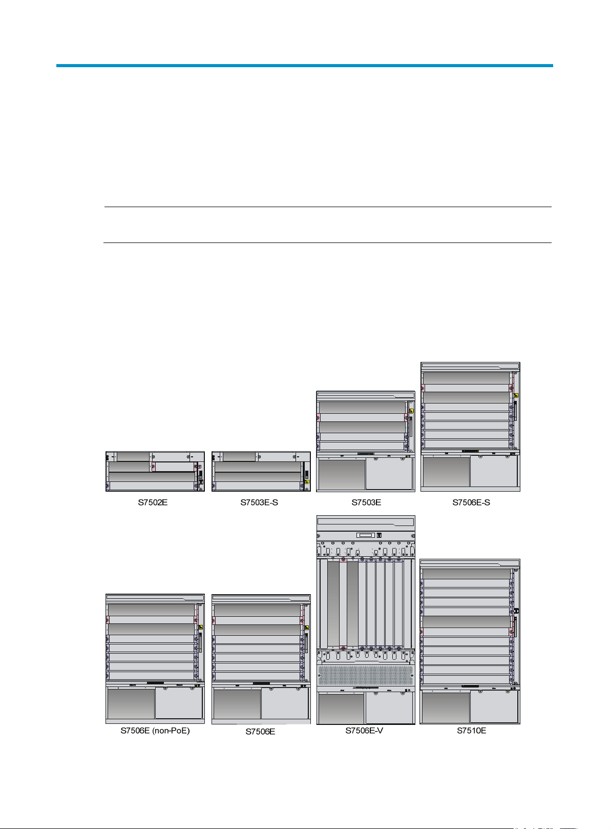
Figure 1 Chassis
1
Page 5

Figure 2 S7503E switch front panel
g
Dep
p
p
(1) MPU slots (2) LPU slots
(3) Power module slots (4) Fan tray slot
Technical specifications
Table 1 Chassis dimensions
Model Hei
S7502E 175 mm (6.89 in) (4 RU) 436 mm (17.17 in) 420 mm (16.54 in)
S7503-S 175 mm (6.89 in) (4 RU) 436 mm (17.17 in) 420 mm (16.54 in)
S7503E 441 mm (17.36 in) (10 RU) 436 mm (17.17 in) 420 mm (16.54 in)
S7506E-S 575 mm (22.64 in) (13 RU) 436 mm (17.17 in) 420 mm (16.54 in)
S7506E (non-PoE) 575 mm (22.64 in) (13 RU) 436 mm (17.17 in) 420 mm (16.54 in)
S7506E 575 mm (22.64 in) (13 RU) 436 mm (17.17 in) 420 mm (16.54 in)
S7506E-V 930 mm (36.61 in) (21 RU) 436 mm (17.17 in) 420 mm (16.54 in)
S7510E 708 mm (27.87 in) (16 RU) 436 mm (17.17 in) 420 mm (16.54 in)
ht Width
th
Table 2 Power module specifications
Model Rated voltage range
PSR320-A
PSR320-D –48 VDC to –60 VDC 300 W No N/A
100 VAC to 240 VAC @
50/60Hz
Maximum output
ower
300 W No N/A
Support for PoE
Maximum PoE
ut power
out
PSR650-A
PSR650-D –48 VDC to –60 VDC 650 W No N/A
100 VAC to 240 VAC @
50/60Hz
650 W No N/A
2
Page 6

Model Rated voltage range
p
p
Maximum output
ower
Support for PoE
Maximum PoE
ut power
out
PSR650C-12A
PSR650C-12D –48 VDC to –60 VDC 650 W No N/A
PSR1400-A
PSR1400-D –48 VDC to –60 VDC 1400 W Yes 6720 W
PSR1400-12D1 –48 VDC to –60 VDC 1400 W No N/A
PSR2800-ACV
100 VAC to 240 VAC @
50/60Hz
100 VAC to 240 VAC @
50/60Hz
100 VAC to 240 VAC @
50/60Hz
650 W No N/A
1150 W (110
VAC)
1400 W (220
VAC)
1150 W (110
VAC)
1400 W (220
VAC)
No N/A
No N/A
Yes 1150 W
Yes 1400 W
• One PoE input:
1150 W (110
VAC)
Yes
• Two PoE inputs:
• Three PoE
PSR6000-ACV
100 VAC to 240 VAC @
50/60Hz
1400 W (220
VAC)
Yes
• One PoE input:
• Two PoE inputs:
• Three PoE
1200 W
2400 W
inputs: 3600 W
1800 W
3600 W
inputs: 5300 W
Table 3 Power module and chassis compatibility matrix
Chassis
Power module
S7502E
PSR320-A
PSR320-D
PSR650-A
PSR650-D
PSR650C-12A — —
PSR650C-12D — —
PSR1400-A — —
PSR1400-D — —
PSR1400-12D1 — —
PSR2800-ACV — —
z
z
z
z
S7503E
-S
z
z
z
z
S7503
E
— — — — — —
— — — — — —
{
{
z
z
z
z
z
z
3
S7506E
{
{
z
z
z
z
z
z
S7506E
-S
{
{
—
—
z
z
z
z
S7506E
(non-PoE)
{
{
z
z
z
z
z
—
S7506E
-V
{
{
z
z
z
z
z
z
S7510
E
—
—
z
z
z
z
z
z
Page 7
Chassis
Power module
S7502E
PSR6000-ACV — —
S7503E
-S
S7503
E
z
NOTE:
• "z" indicates that the power module can be directly installed on the chassis.
• "{" indicates that you must first install a power module adapter on the chassis and then install the power
module on the power module adapter.
• "—" indicates that the power module cannot be installed on the chassis.
Safety recommendations
To avoid equipment damage or bodily injury caused by improper use, read the following safety
recommendations before installation. Note that the recommendations do not cover every possible
hazardous condition.
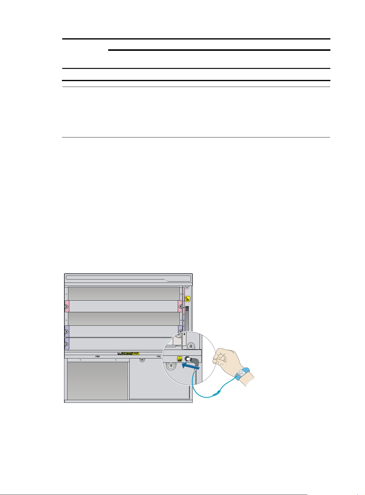
• To prevent ESD damage, always wear an ESD wrist strap and make sure it is reliably grounded
before you touch the switch, cards, or PCB.
• Do not install the switch, FRUs, or cables when the switch is powered on.
S7506E
z
S7506E
-S
z
S7506E
(non-PoE)
—
S7506E
-V
z
S7510
E
z
• To avoid equipment damage or bodily injury, make sure the switch is reliably grounded before
powering on the switch.
• To ensure good ventilation, install a blank filler panel in an unused slot.
Figure 3 Attaching an ESD wrist strap
4
Page 8

Examining the installation site
g
g
The switch can only be used indoors. To make sure the switch operates correctly and prolong its service
lifetime, the installation site must meet the requirements for load-bearing, temperature, humidity,
cleanness, EMI, grounding power module, ventilation, and space. For more information, see H3C
S7500E Switch Series Installation Guide.
Installing the switch
Attaching the slide rails to the rack
1. Read the signs on the slide rails to identify the left and right slide rails and their front ends, as
shown in Table 4.
Table 4 Description f
Si
n Meanin
F/L Front end of the left slide rail Mount this end to the front left rack post.
F/R Front end of the right slide rail Mount this end to the front right rack post.
2. Mark the installation position on the rack for the slide rails:
a. Make sure the top flange of a slide rail aligns with the middle of the narrower metal area
between holes in a rack post, as shown in Figure 4.
b. Eac
c. Mark the square holes at the same height on the other three rack posts.
Figure 4 Determining the cage nut installation holes by using a slide rail
h rack post requires six screws to attach the slide rail. Mark only the uppermost and
lowermost holes.
or signs on the slide rails
Remarks
(1) Middle of the narrower metal area between holes
3. Install six cage nuts in the square holes in each rack post, as shown in Figure 5.
5
Page 9

Figure 5 Installing a cage nut
4. Align the installation holes on the front end of a slide rail with the cage nuts on a front rack post,
and use six screws to attach the slide rail to the front rack post. Figure 6 us
es the right slide rail as
an example.
Figure 6 Attaching the right slide rail to the front right rack post
5. Keep the slide rail horizontal and adjust its length until the installation holes on the rear end of the
slide rail touch the cage nuts on the rear rack post. Then use screws to attach the slide rail to the
rear rack post.
6. Repeat steps 4 and 5 to install the other slide rail. Make sure the two slide rails are at the same
height so that the switch can be placed on them horizontally.
Installing cage nuts
1. Determine and mark the cage nut installation holes on the front rack posts ,as shown in Figure 7.
6
Page 10

Figure 7 Cage nut installation holes
1
1
1
1
(1) Cage nuts
Figure 8 Marking the cage nut installation holes
2. Install the cage nuts.
7
Page 11

Installing mounting brackets and cable management brackets
Installing the cable management brackets on the S7506E-V
The S7506E-V has two cable management brackets: the one with a tray is installed at the lower part of
the switch, and the one without a tray is installed at the upper part of the switch. They are installed in the
same way.
To install a cable management bracket:
1. Unpack the cable management brackets.
2. Attach the cable management bracket to the chassis, and align the screws with the screw holes in
the chassis, as shown in Figure 9.
3. Fasten the s
Figure 9 Installing cable management brackets on an S7506E-V
crews.
Installing the cable management brackets on other models
For the models except the S7506E-V, install the cable management bracket on the left mounting bracket,
as shown in Figure 10. T
management bracket screw holes is the left mounting bracket.
he switch is supplied with two mounting brackets, and the one with the cable
8
Page 12

Figure 10 Attaching the cable management bracket to the left mounting bracket
Installing the mounting brackets
Before installing the switch in the rack, install the mounting brackets to the chassis, as shown in Figure 11.
• S7506E-V—Facing the front of the switch, mount the left and right mounting brackets to the two
sides of the switch.
• Other models—Facing the front of the switch, mount the mounting bracket with a cable
management bracket to the left of the switch, and mount the mounting bracket without a cable
management bracket to the right of the switch (where the fan tray is located).
Figure 11 Installing the mounting brackets
2
1
Installing the switch in the rack
2
1
Follow these guidelines when you install the switch in the rack:
• To avoid equipment damage or bodily injury, use a minimum of two people to lift the switch. H3C
recommends that you use a mechanical lift to move the switch.
9
Page 13

• Do not hold the filler panels, filler panel handles, or the air vents of chassis to carry the chassis. Any
g
attempt to carry the switch with these parts might cause equipment damage or even bodily injury.
• After placing the switch on the slide rails, do not leave go of your hands immediately because this
might tip the switch. Tipping the switch can cause switch damage and even bodily injury.
Figure 12 Installing the switch in the rack
1
Grounding the switch
CAUTION:
Connect the
main or lightning rod.
Use the provided grounding cable (yellow-green grounding cable).
rounding cable to the grounding system in the equipment room. Do not connect it to a fire
2
2
10
Page 14

Figure 13 Grounding the switch
Installing FRUs
Installing a card
IMPORTANT:
• Before installing a card in the chassis, make sure the connectors on the card are not broken or blocked.
• To ensure good ventilation, install a blank filler panel in an empty slot.
11
Page 15

Figure 14 Installing a card
1
2
3
4
Installing a power module
CAUTION:
• Provide a circuit breaker for each power module and make sure the circuit breaker is off before
installation.
• Do not install power modules of different models on the same switch.
• For dual-grid input, the input voltage and frequency for the two grids must be the same.
• To avoid power module damage or bodily injury, support the bottom of a power module instead of
holding its handle to move the power module.
• To ensure good ventilation, install a blank filler panel over an empty slot.
After you push the power module into the slot, press the power module handle inward until it is secured
in place, and then fasten the captive screws on the power module.
12
Page 16

Figure 15 Installing a power module
13
Page 17

Connecting power cords
Connecting the PSR320-A/PSR650-A power cord
Figure 16 Connecting the PSR320-A/PSR650-A power cord
Connecting the PSR650C-12A power cord
Figure 17 Connecting the PSR650C-12A power cord
14
Page 18

Connecting the PSR1400-A power cord
Figure 18 Connecting the PSR1400-A power cord
1
2
5
1
6
3
4
A
Connecting the PSR2800-ACV power cord
The PSR2800-ACV is a built-in power module with AC input and DC output. It provides one system power
socket and one PoE power socket. The methods for connecting the system power cord and PoE power
cord are similar to connecting the PSR1400-A power cord. For more information, see "Connecting the
PS
R1400-A power cord."
Connecting the PSR6000-ACV power cord
The PSR6000-ACV is a built-in power module with AC input and DC output. It provides one system power
socket and three PoE power sockets. Connecting the system power cord is the same as connecting the
PoE power cord. The following illustrates how to connect the system power cord.
To attach the power cord retainer suite:
1. Fasten the retainer suite to the plug of the power cord, making sure you can align the screw holes
in the retainer suite with the screw holes in the power module.
If you cannot align the screw holes in the retainer suite with the screw holes in the power module,
pull the cable retainer suite outwards, rotate it by 180 degrees, and push it in until it is secured in
place.
2. Use a Phillips screwdriver to fasten the two parts of the retainer suite together.
6
15
Page 19

Figure 19 Attaching the power cord retainer suite
(1) Screw holes for connecting the retainer suite to the power module (2) Power cord plug
(3) Screw holes for connecting the two parts of the retainer suite
3. Insert the power cord into the power socket on the power module, and fasten the power cord
retainer suite to the power module.
Figure 20 Connecting the AC power cord to the PSR6000-ACV
1
6
A
1
2
16
Page 20

Connecting the PSR320-D/PSR650-D/PSR650C-12D power cord
Figure 21 Connecting the PSR320-D/PSR650-D/PSR650C-12D power cord
Connecting the PSR1400-D/PSR1400-12D1 power cord
Figure 22 Connecting the PSR1400-D/PSR1400-12D1 power cord
1
2
3
6
5
4
17
Page 21

Accessing the switch for the first time
Connecting the console cable
The first time you access the switch you must use a console cable to connect a console terminal, for
example, a PC, to the console port or USB console port on the switch. If both the console port and USB
console port are connected to terminals, you can only access the switch through the USB console port.
To connect the console cable to the console port:
1. Connect the DB-9 connector of the console cable to the 9-core serial port on the terminal.
2. Connect the crimped RJ-45 connector of the console cable to the console port on the switch.
To connect the console cable to the USB console port:
1. Connect the USB A connector of the console cable to the USB port on the terminal.
2. Connect the mini-USB A/B connector of the console cable to the USB console port on the switch.
Figure 23 Connecting the console port to a PC
Setting terminal parameters
To configure and manage the switch through the console port, you must run a terminal emulator program,
HyperTerminal or PuTTY, on your configuration terminal. You can use the emulator program to connect a
network device, a Telnet site, or an SSH site. For more information about the terminal emulator programs,
see the user guides for these programs.
The following are the required terminal settings:
• Bits per second—9,600.
• Data bits—8.
• Stop bits—1.
18
Page 22

• Parity—None.
• Flow control—None.
Powering on the switch
1. Make sure the power cords are connected correctly to the power source, and the power source is
supplying power correctly.
2. Turn on the circuit breakers for the power modules.
3. Power on the switch.
4. Verify that the LEDs on the switch are in the states as described Table 5. For more information
about the LED
Table 5 LED status when the switching is operating correctly
s, see H3C S7500E Switch Series Installation Guide.
Item Model LED
LINK/ACT Steady on or flashing
OK Steady on
LSQM3MPUA0
• LSQ1MPUA0
FAIL Off
RUN Flashing
ALM Steady on or off
LINK Steady on
• LSQ1CGV24PSC0
• LSQ1CGP24TSC0
ACT Flashing or off
• LSQ1CTGS16SC0
MPU
• LSQ1MPUB0 (Salience VI-Lite)
• LSQ1SRPA0 (Salience VI-Smart)
• LSQ1SRPB0 (Salience VI)
OK Steady on
FAIL Off
• LSQ1SRPD0 (Salience VI-Plus)
• LSQ1SRP1CB0 (Salience VI-Turbo)
• LSQ1SRP12GB0 (Salience VI-GE)
RUN Flashing
• LSQ1SRP2XB0 (Salience VI-10GE)
• LSQM3MPUB0
• LSQM2MPUC0
• LSQM2MPUD0
• LSQM2MPUDS0
• LSQM1SRP8X2QE0
ACT Steady on or off
LINK Steady on
ACT Flashing or off
PWR/FAN Steady green
SLOT Flashing green
• PSR320-A
Power module
• PSR320-D
• PSR650 -A
Power module status
LED
• PSR650 -D
Status
Steady green
19
Page 23

Item Model LED
• PSR650C-12A
• PSR650C-12D
INPUT Steady green
OUTPUT Steady green
• PSR1400-A
• PSR1400-D
FAN Steady green
• PSR1400-12D1
INPUT Steady green
OUTPUT Steady green
Status
PSR2800-ACV
PSR6000-ACV
Obtaining documentation
Take the following steps to get related documents from the H3C website at www.h3c.com.hk.
1. Go to http://www.h3c.com.hk/Technical_Documents
FAN Steady green
PoE INPUT Steady green
PoE OUTPUT Steady green
SYS IN Steady green
SYS OUT Steady green
SYS FAN Steady green
PoE IN1 Steady green
PoE IN2 Steady green
PoE IN3 Steady green
PoE OUT Steady green
PoE FAN Steady green
.
2. Choose the desired product category and model.
20
 Loading...