

Page 1

Hangzhou H3C Technologies Co., Ltd.
http://www.h3c.com
Document version: 6W102-20130626
H3C S5830 Switch Series
Installation Guide
Page 2

Copyright © 2011-2013, Hangzhou H3C Technologies Co., Ltd. and its licensors
All rights reserved
No part of this manual may be reproduced or transmitted in any form or by any means without prior
written consent of Hangzhou H3C Technologies Co., Ltd.
Trademarks
H3C,
SecEngine, SecPath, SecCenter, SecBlade, Comware, ITCMM and HUASAN are trademarks of
Hangzhou H3C Technologies Co., Ltd.
All other trademarks that may be mentioned in this manual are the property of their respective owners
Notice
The information in this document is subject to change without notice. Every effort has been made in the
preparation of this document to ensure accuracy of the contents, but all statements, information, and
recommendations in this document do not constitute the warranty of any kind, express or implied.
Environmental protection
This product has been designed to comply with the environmental protection requirements. The storage,
use, and disposal of this product must meet the applicable national laws and regulations.
, H3CS, H3CIE, H3CNE, Aolynk, , H3Care,
, IRF, NetPilot, Netflow,
Page 3

Preface
The H3C S5830 Switch Series Installation Guide guides you through the installation of your switch. It
covers product overview, preparing for installation, installing the switch, powering on the switch for the
first time, setting up an IRF fabric, and troubleshooting.
This preface includes:
• Audience
• Conventions
• Obtaining documentation
• Technical support
• Documentation feedback
Audience
This documentation is intended for:
• Network planners
• Field technical support and servicing engineers
• Network administrators working with the S5830 switch series
Conventions
This section describes the conventions used in this documentation set.
GUI conventions
Convention Description
Boldface
> Multi-level menus are separated by angle brackets. For example, File > Create > Folder.
Convention Description
< > Button names are inside angle brackets. For example, click <OK>.
[ ]
/ Multi-level menus are separated by forward slashes. For example, [File/Create/Folder].
Window names, button names, field names, and menu items are in Boldface. For
example, the New User window appears; click OK.
Window names, menu items, data table and field names are inside square brackets. For
example, pop up the [New User] window.
Page 4
Symbols
Convention Description
WARNING
CAUTION
IMPORTANT
NOTE
TIP
Network topology icons
Port numbering in examples
The port numbers in this document are for illustration only and might be unavailable on your device.
An alert that calls attention to important information that if not understood or followed can
result in personal injury.
An alert that calls attention to important information that if not understood or followed can
result in data loss, data corruption, or damage to hardware or software.
An alert that calls attention to essential information.
An alert that contains additional or supplementary information.
An alert that provides helpful information.
Represents a generic network device, such as a router, switch, or firewall.
Represents a routing-capable device, such as a router or Layer 3 switch.
Represents a generic switch, such as a Layer 2 or Layer 3 switch, or a router that supports
Layer 2 forwarding and other Layer 2 features.
Obtaining documentation
You can access the most up-to-date H3C product documentation on the World Wide Web at
http://www.h3c.com
Click the links on the top navigation bar to obtain different categories of product documentation:
[Technical Support & Documents > Technical Documents]
upgrading, and software feature configuration and maintenance documentation.
[Products & Solutions]
[Technical Support & Documents > Software Download]
software version.
.
– Provides information about products and technologies, as well as solutions.
Technical support
service@h3c.com
http://www.h3c.com
Documentation feedback
You can e-mail your comments about product documentation to info@h3c.com.
– Provides hardware installation, software
– Provides the documentation released with the
We appreciate your comments.
Page 5

Contents
Product overview·························································································································································· 1
S5830-52SC panel views················································································································································1
S5830-106S panel views ················································································································································2
Preparing for installation ············································································································································· 4
Safety recommendations ··················································································································································4
Examining the installation site ·········································································································································4
Temperature/humidity ·············································································································································4
Cleanness··································································································································································5
EMI·············································································································································································5
Laser safety································································································································································5
Installation tools·································································································································································6
Installing the switch······················································································································································ 7
Installing the switch in a 19-inch rack·····························································································································8
Mounting bracket and cable management bracket kits ·······················································································8
Rack mounting rail kit ··············································································································································9
Installation methods··············································································································································· 10
Installing the mounting brackets, chassis rails, and grounding cable (for the S5830-52SC) ······················· 11
Installing the mounting brackets, chassis rails, and grounding cable (for the S5830-106S) ······················· 13
Rack-mounting the S5830-52SC switch·············································································································· 15
Rack-mounting the S5830-106S switch ·············································································································· 17
Grounding the switch ···················································································································································· 20
Grounding the switch with a grounding strip····································································································· 20
Grounding the switch through the PE wire of an AC power cord ··································································· 21
Installing/removing a fan tray ······································································································································ 21
Selecting a fan tray ··············································································································································· 21
Installing a fan tray ··············································································································································· 22
Removing a fan tray·············································································································································· 23
Installing/removing a power module··························································································································· 23
Installing/removing a power module·················································································································· 23
Connecting the power cord ·········································································································································· 26
Connecting the AC power cord··························································································································· 26
Connecting the DC power cord··························································································································· 26
Installing/removing an interface card ························································································································· 27
Installing an interface card··································································································································· 27
Removing an interface card ································································································································· 28
Verifying the installation················································································································································ 28
Powering on the switch for the first time···················································································································30
Setting up the configuration environment···················································································································· 30
Connecting the console cable ······································································································································30
Console cable························································································································································ 30
Connection procedure ·········································································································································· 30
Setting terminal parameters ·········································································································································· 31
Powering on the switch·················································································································································· 34
Setting up an IRF fabric ·············································································································································35
IRF fabric setup flowchart·············································································································································· 35
Planning IRF fabric setup··············································································································································· 36
Planning IRF fabric size and the installation site································································································ 36
i
Page 6

Identifying the master switch and planning IRF member IDs ············································································ 36
Planning IRF topology and connections ·············································································································· 37
Identifying physical IRF ports on the member switches ····················································································· 38
Planning the cabling scheme ······························································································································· 38
Configuring basic IRF settings······································································································································· 40
Connecting the physical IRF ports ································································································································41
Accessing the IRF fabric to verify the configuration ··································································································· 41
Maintenance and troubleshooting ····························································································································42
Power module failure····················································································································································· 42
Fan failure······································································································································································· 42
Configuration terminal problems·································································································································· 42
Appendix A Technical specifications························································································································44
Technical specifications················································································································································· 44
Cooling system ······························································································································································· 45
Cooling system of the S5830-52SC···················································································································· 45
Cooling system of the S5830-106S···················································································································· 46
Appendix B FRUs and compatibility matrixes··········································································································48
Hardware compatibility matrix····································································································································· 48
Hot swappable power modules···································································································································· 48
Hot swappable fan trays··············································································································································· 49
Interface cards································································································································································ 50
Appendix C Ports and LEDs ······································································································································51
Ports ················································································································································································· 51
Console port··························································································································································· 51
Management Ethernet port··································································································································· 51
10/100/1000Base-T Ethernet port ···················································································································· 51
SFP port ·································································································································································· 52
SFP+ port································································································································································ 54
LEDs ················································································································································································· 56
System status LED··················································································································································· 57
10/100/1000Base-T Ethernet port LED············································································································· 57
SFP port LED··························································································································································· 57
SFP+ port LED ························································································································································ 58
Management Ethernet port LEDs·························································································································· 58
Interface card status LED······································································································································· 58
Index ···········································································································································································59
ii
Page 7
Product overview
The H3C S5830 Switch Series includes the following models:
• S5830-52SC
• S5830-106S
This chapter describes the chassis panel views of the S5830 switches.
S5830-52SC panel views
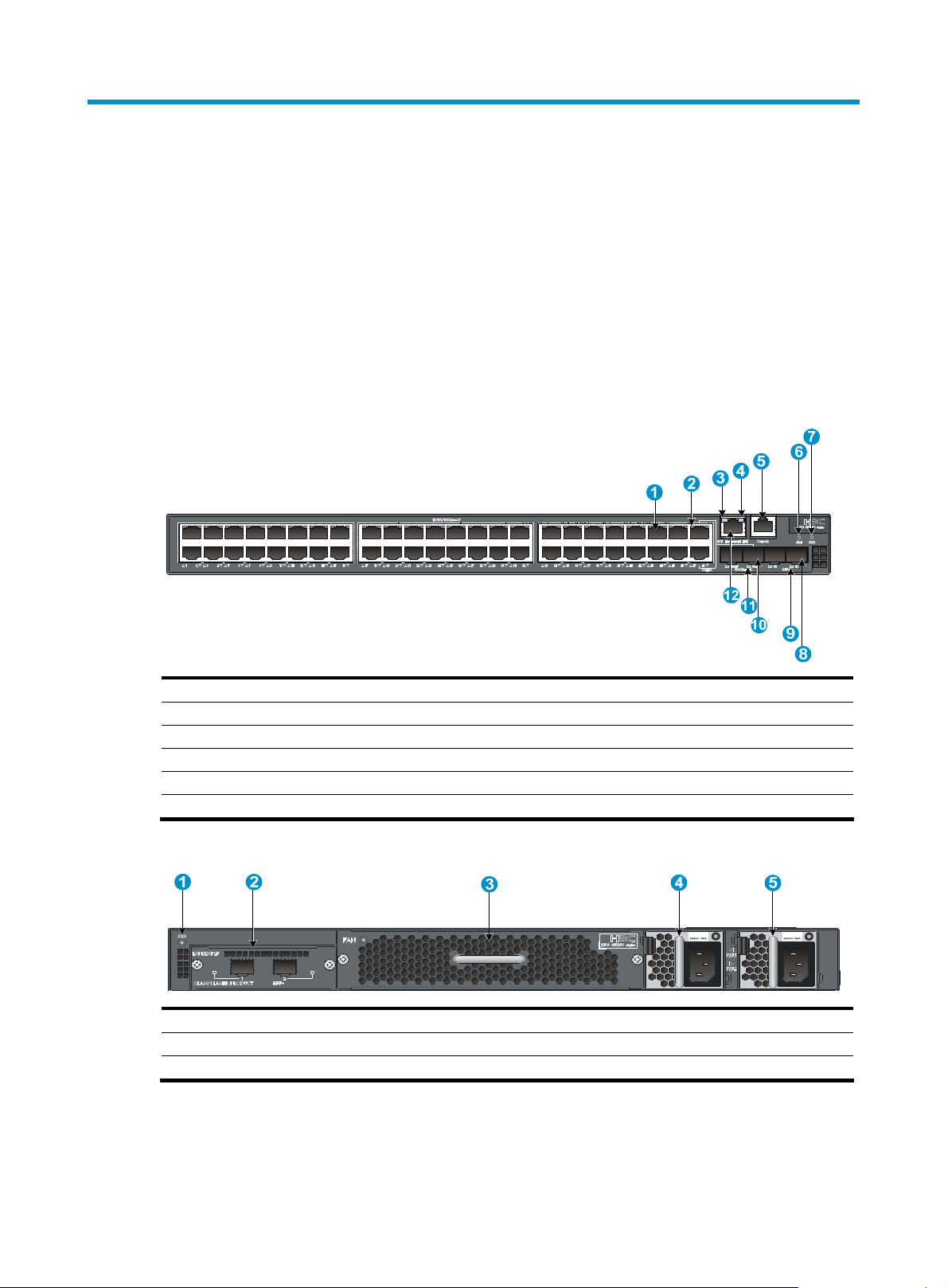
Figure 1 S5830-52SC front panel
(1) 10/100/1000Base-T auto-sensing Ethernet port (2) 10/100/1000Base-T Ethernet port LED
(3) ACT LED for the management Ethernet port (4) LINK LED for the management Ethernet port
(5) Console port (6) Interface card status LED (Slot)
(7) System status LED (SYS) (8) SFP+ port
(9) SFP+ port LED (10) 1000Base-X SFP port
(11) SFP port LED (12) Management Ethernet port
Figure 2 S5830-52SC rear panel
1
00-240Vac
(1) System status LED (SYS) (2) Expansion interface card slot
(3) Fan tray slot (4) Power module slot 1 (PWR1)
(5) Power module slot 2 (PWR2)
100-240Vac
1
Page 8
NOTE:
The S5830-52SC switch comes with one expansion interface card slot, one fan tray slot, and two power
modules slots with filler panels. In this figure, two LSVM1AC650 AC power modules, one
LSWM152SCFAN fan tray, and one LSPM2SP2P expansion interface card are installed.
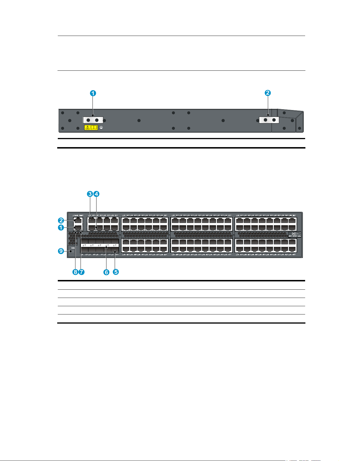
Figure 3 S5830-52SC left side panel
(1) Primary grounding point (2) Auxiliary grounding point
S5830-106S panel views
Figure 4 S5830-106S front panel
(1) Management Ethernet port (2) Console port
(3) 10/100/1000Base-T auto-sensing Ethernet port (4) 10/100/1000Base-T -Ethernet port LED
(5) SFP+ port (6) SFP+ port LED
(7) LINK LED for the management Ethernet port (8) ACT LED for the management Ethernet port
(9) System status LED (SYS)
2
Page 9
NOTE:
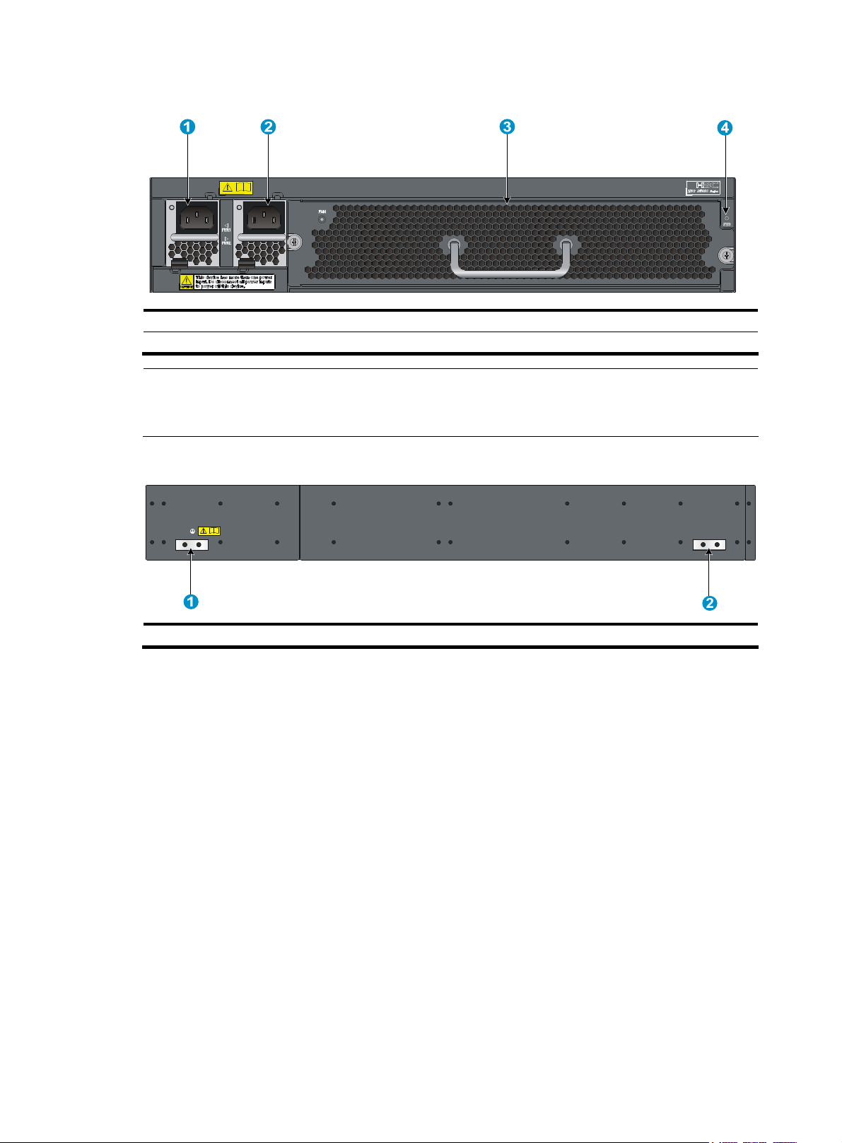
Figure 5 S5830-106S rear panel
(1) Power module slot 1 (PWR1) (2) Power module slot 2 (PWR2)
(3) Fan tray slot (4) System status LED (SYS)
The S5830-106S switch comes with one fan tray slot and two power modules slots with filler panels. In this
figure, two LSVM1AC650 AC power modules and one LSVM1106SFAN fan tray are installed.
Figure 6 S5830-106S left side panel
(1) Primary grounding point (2) Auxiliary grounding point
3
Page 10

Preparing for installation
Safety recommendations
To avoid any equipment damage or bodily injury caused by improper use, read the following safety
recommendations before installing an H3C S5830 switch. Note that the recommendations do not cover
every possible hazardous condition.
• Before cleaning the switch, unplug the power cord of the power module of the switch. Do not clean
the switch with wet cloth or liquid.
• Do not place the switch near water or in a damp environment. Prevent water or moisture from
entering the switch chassis.
• Do not place the switch on an unstable case or desk. The switch might be severely damaged in case
of a fall.
• Ensure proper ventilation of the equipment room and keep the ventilation vents of the switch free of
obstruction.
• Make sure the operating voltage is in the range labeled on the power module of the switch.
• To avoid electrical shocks, do not open the chassis when the switch is operating or when the switch
is just powered off.
• When replacing interface cards, hot-swappable power modules and fan trays, wear an
ESD-preventive wrist strap to avoid damaging the units.
Examining the installation site
The H3C S5830 Switch Series must be used indoors. You can mount the switch in a rack, but make sure:
• Adequate clearance is reserved at the air inlet and exhaust vents for ventilation.
• The rack has a good ventilation system.
• Identify the hot aisle and cold aisle at the installation site, and make sure ambient air flows into the
switch from the cold aisle and exhausts to the hot aisle.
• Identify the airflow designs of neighboring devices, and prevent hot air flowing out of the bottom
device from entering the top device.
• The rack is sturdy enough to support the switch and its accessories.
• The rack is well earthed.
To ensure normal operation and long service life of your switch, install it in an environment that meets the
requirements described in the following subsections.
Temperature/humidity
You must maintain a proper temperature and humidity in the equipment room. Long-term high humidity
may lead to bad insulation, electricity leakage, mechanical property changes, and metal corrosion.
However, if the relative humidity is too low, captive screws may become loose as the result of contraction
of insulation washers and static electricity may be produced in a dry environment to jeopardize the
4
Page 11

circuits on the device. A high temperature is the most undesirable condition, because it accelerates the
aging of insulation materials and significantly lowers reliability and service life of the switch.
For the temperature and humidity requirements of different switch models, see Table 9 in Appendix A
Technical specifications.
Cleanness
Dust buildup on the chassis may result in electrostatic adsorption, which causes poor contact of metal
components and contact points, especially when indoor relative humidity is low. In the worst case,
electrostatic adsorption can cause communication failure.
Table 1 Dust concentration limit in the equipment room
Substance Concentration limit (particles/m³)
EMI
Dust
NOTE:
The dust diameter is greater than or equal to 5 μm.
≤ 3 x 10⁴ (no visible dust on the tabletop over three days)
The equipment room must also meet strict limits on salts, acids, and sulfides to eliminate corrosion and
premature aging of components, as shown in Table 2.
Table 2 Harmful gas limits in the equipment room
Gas Maximum concentration (mg/m
SO
2
H2S 0.006
NH3 0.05
Cl2 0.01
0.2
3
)
All electromagnetic interference (EMI) sources, from outside or inside of the switch and application
system, adversely affect the switch in a conduction pattern of capacitance coupling, inductance coupling,
electromagnetic wave radiation, or common impedance (including the grounding system) coupling.
To prevent EMI, take the following actions:
• If AC power is used, use a single-phase three-wire power receptacle with protection earth (PE) to
filter interference from the power grid.
• Keep the switch far away from radio transmitting stations, radar stations, and high-frequency
devices.
• Use electromagnetic shielding, for example, shielded interface cables, when necessary.
• Route interface cables only indoors to prevent signal ports from getting damaged by over-voltage or
over-current caused by lightning strikes.
Laser safety
The H3C S5830 Switch Series is a line of class 1 laser devices.
5
Page 12

g
WARNING!
Do not stare into any fiber port when the switch has power. The laser li
may hurt your eyes.
Installation tools
• Flat-blade screwdriver P4-75mm
• Phillips screwdriver P1-100mm, P2-150mm, and P3-250mm
• ESD-preventive wrist strap
All these installation tools are user supplied.
ht emitted from the optical fiber
6
Page 13
g
Installing the switch
CAUTION:
Keep the tamper-proof seal on a mountin
chassis, contact the local agent of H3C for permission. Otherwise, H3C shall not be liable for any
consequence caused thereby.
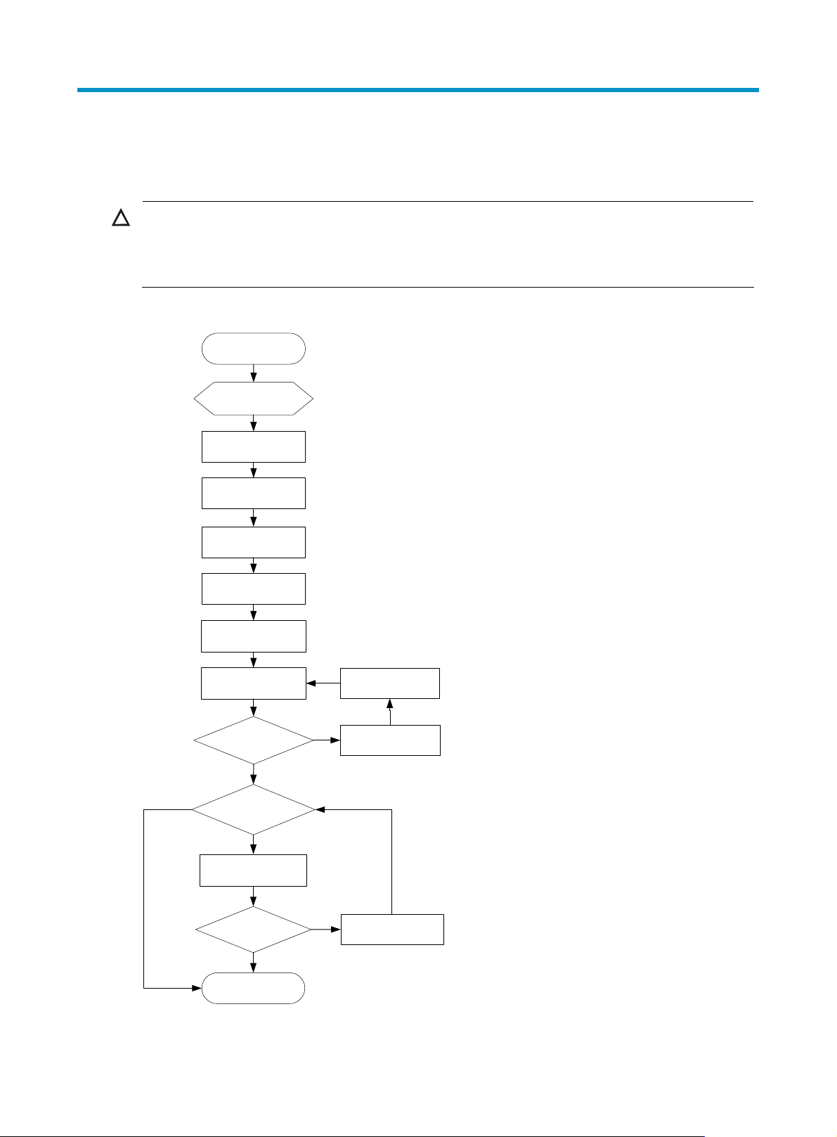
Figure 7 Hardware installation flow
Start
Install to a
specified
position
Ground the switch
screw on the chassis cover intact, and if you want to open the
Install a fan tray
Connect the power
No
Install an interface
Install a power
module
cord
Verify the
installation
Power on the
switch
Operating
properly?
Yes
card?
Yes
Verify the
installation
Troubleshoot the
No
Power off the
switch
switch
No
Operating
properly?
Yes
End
Troubleshoot the
switch
7
Page 14
NOTE:
The S5830-106S does not support expansion interface card. You can skip the step for installing an
expansion interface card when installing an S5830-106S switch.
Installing the switch in a 19-inch rack
Mounting bracket and cable management bracket kits
Table 3 Mounting bracket and cable management bracket kits for the H3C S5830 Switch Series
Switch models Mounting brackets
One pair of 1U
S5830-52SC
S5830-106S
mounting brackets
(supplied with the
switch)
One pair of 2U
mounting brackets
(supplied with the
switch)
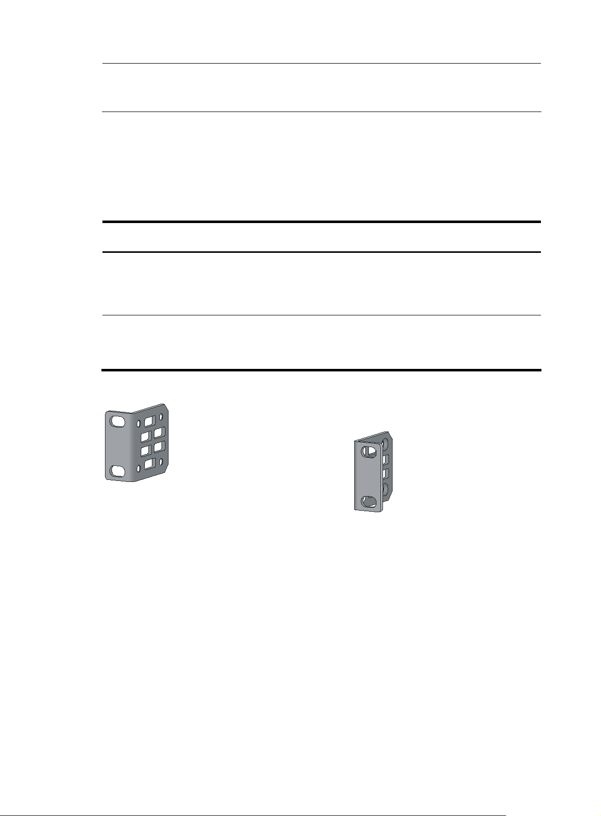
Figure 8 1U mounting bracket kit
Cable management
brackets
N/A See Figure 8.
One pair (supplied with the
switch)
Bracket view
The mounting brackets and
cable management brackets
are secured together by default
(see Figure 9).
8
Page 15
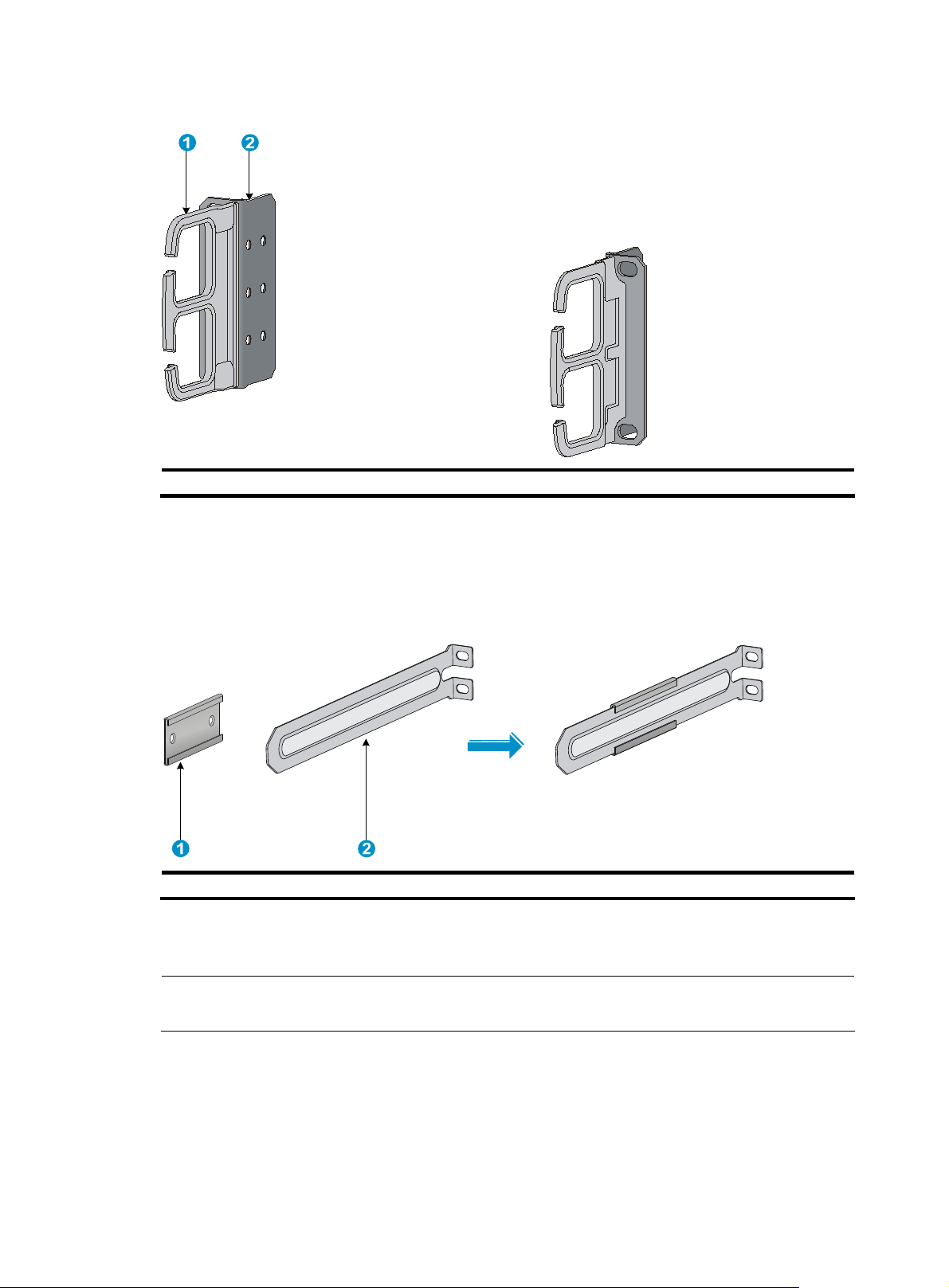
Figure 9 2U cable management bracket and mounting bracket kit
(1) Cable management bracket (2) Mounting bracket
Rack mounting rail kit
The S5830 switch comes with a pair of chassis rails and a pair of slide rails.
Figure 10 Chassis rail and slide rail kit for the S5830-52SC
(1) Chassis rail (2) Slide rail
For the S5830-52SC, H3C provides slide rails of two sizes to install the switch in racks of different depths.
For more information, see Table 5.
NOTE:
To order long slide rails, contact the H3C marketing personnel or local dealer.
9
Page 16
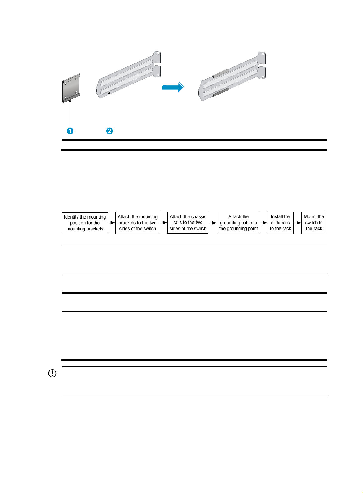
Figure 11 Chassis rail and slide rail kit for the S5830-106S
(1) Chassis rail (2) Slide rail
Installation methods
You can install the H3C S5830 Switch Series in a 19-inch rack by using mounting brackets, chassis rails,
and slide rails, as shown in Figure 12.
Figure 12 Installing an S5830 switch in a 19-inch rack
NOTE:
If a rack shelf is available, you can put the switch on the rack shelf, slide the switch to an appropriate
location, and fix the switch to the rack with the mounting brackets.
Table 4 Installing an S5830 switch in the rack
Mounting bracket
position
• Rear mounting
(near the power
modules)
• Front mounting
(near the network
ports)
IMPORTANT:
Installing the chassis rails and slide rails Installing the switch
• See "Installing the mounting brackets,
chassis rails, and grounding cable (for the
S5830-52SC)"
• See "Installing the mounting brackets,
chassis rails, and grounding cable (for the
S5830-106S)"
• See "Rack-mounting the
S5830-52SC switch"
• See "Rack-mounting the
S5830-106S switch"
To mount the switch steadily in a rack, you must also install slide rails and chassis rails besides the
mounting brackets.
For the minimum and maximum distances required between front and rear rack posts, see Table 5.
10
Page 17
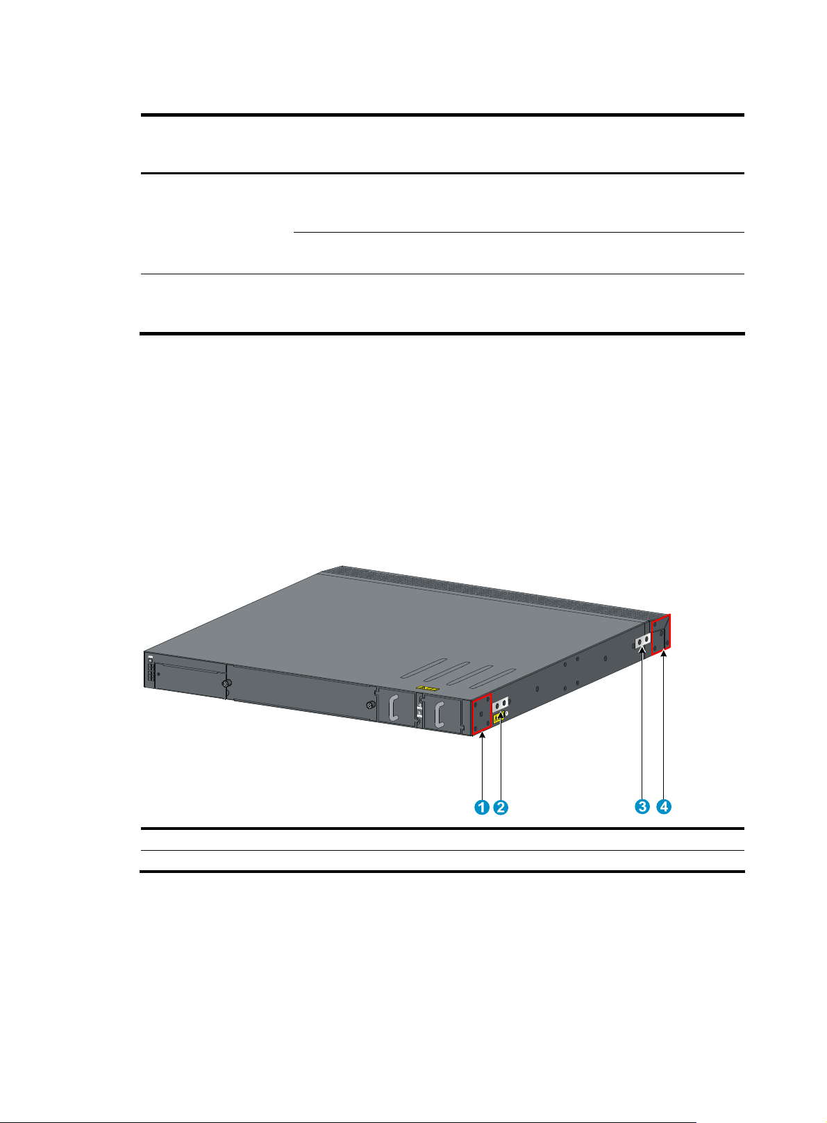
Table 5 Minimum and maximum distances required between front and rear rack posts
Switch model Installation method
Mounting brackets and
short slide rails (supplied
S5830-52SC
S5830-106S
with the switch)
Mounting brackets and
long slide rails (optional)
Mounting brackets and
slide rails (supplied with
the switch)
Minimum distance
between front and
rear rack posts
401 mm (15.79 in) 654 mm (25.75 in)
621 mm (24.45 in) 874 mm (34.41 in)
489 mm (19.25 in) 993 mm (39.09 in)
Maximum distance
between front and
rear rack posts
Installing the mounting brackets, chassis rails, and grounding cable (for the S5830-52SC)
The S5830-52SC switch provides one front mounting position (near the network ports) and one rear
mounting position (near the power modules), and two grounding points (one primary grounding point
with a grounding sign, and one auxiliary grounding point). You use the primary grounding point in most
cases. If the primary grounding point fails or is not suitable for the installation site, use the auxiliary
grounding point.
Figure 13 Identifying the mounting and grounding positions
(1) Rear mounting position (2) Primary grounding point
(3) Auxiliary grounding point (4) Front mounting position
Attaching the mounting brackets and chassis rails to the switch chassis
1. Align the mounting brackets with the screw holes in the rear mounting position (see Figure 14) or
front mounting position (see Figure 15).
2. Use M4 screws (supplied with the switch) to fix the mounting brackets to the chassis.
3. If the mounting brackets are in the rear mounting position, align the chassis rails with the screw
holes at the front of the side panels (see Figure 14). If the mounting brackets are in the front
11
Page 18
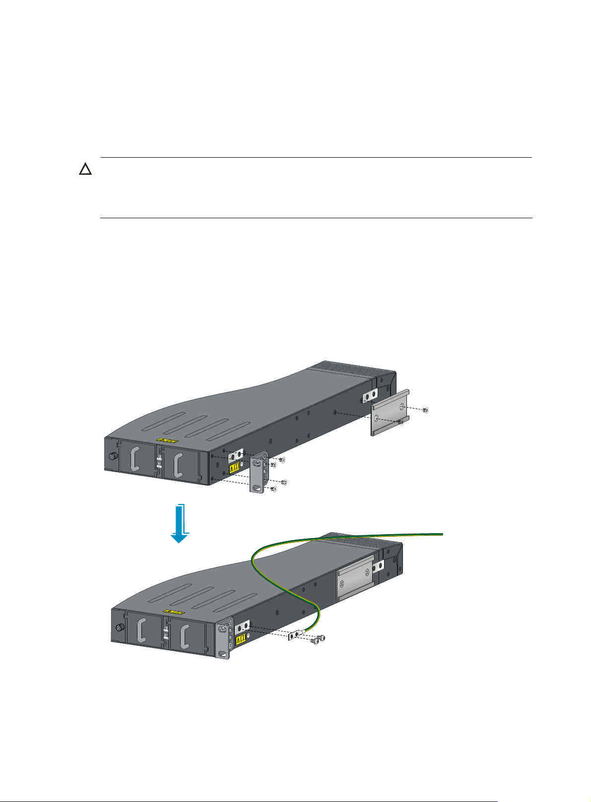
mounting position, align the chassis rails with the screw holes at the rear of the side panels (see
Figure 15).
4. Use M4 screws (supplied with the switch) to fix the chassis rails to the chassis.
Attach the mounting brackets and chassis rails to both sides of the chassis in the same way.
Connecting the grounding cable to the switch chassis
CAUTION:
The primary grounding point and auxiliary grounding point are located on the left side panel. If you use
either of the grounding points, you must connect the grounding cable to the grounding point before you
mount the switch in the rack.
To connect the grounding cable to a chassis grounding point, for example, the primary grounding point:
1. Select a grounding point.
2. Remove the grounding screws from the primary grounding point. (You can use the screws for
connecting to the primary grounding point or the auxiliary grounding point.)
3. Align the two-hole grounding lug at one end of the cable with the grounding holes of the
grounding point, insert the grounding screws into the holes, and tighten the screws with a
screwdriver to fix the grounding lug to the chassis, as shown in Figure 14.
Figure 14 Attaching the rear mounting brackets, chassis rails, and the grounding cable to the chassis
12
Page 19
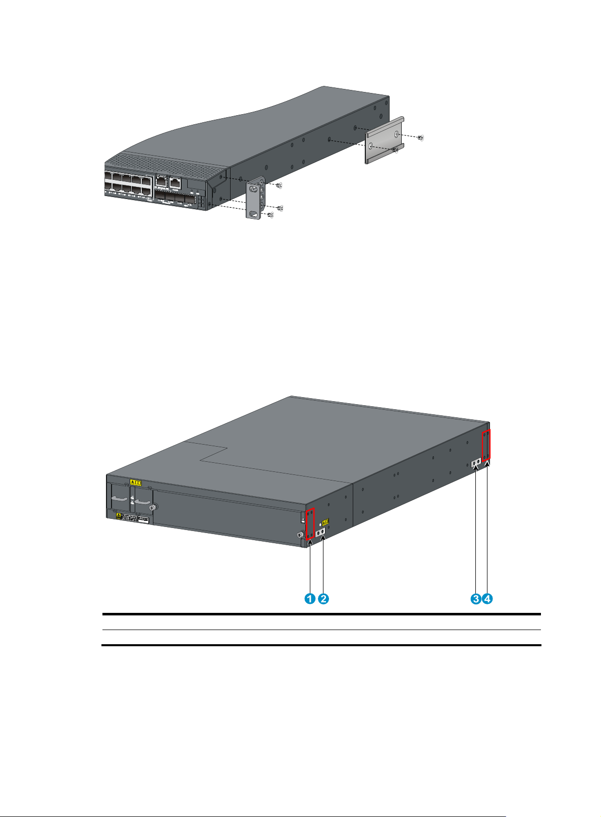
Figure 15 Attaching the front mounting brackets and the chassis rails to the chassis
Installing the mounting brackets, chassis rails, and grounding cable (for the S5830-106S)
The S5830-106S switch provides one front mounting position (near the network ports) and one rear
mounting position (near the power modules), and two grounding points—one primary grounding point
(with a grounding sign), and one auxiliary grounding point. You use the primary grounding point in most
cases. If the primary grounding point fails or is not suitable for the installation site, use the auxiliary
grounding point.
Figure 16 Identifying the mounting and grounding positions
(1) Rear mounting position (2) Primary grounding point
(3) Auxiliary grounding point (4) Front mounting position
Attaching the mounting brackets and chassis rails to the switch chassis
1. Align the mounting brackets with the screw holes in the rear mounting position (see Figure 17) or
front mounting position (see Figure 18).
2. Use M4 screws (supplied with the switch) to fix the mounting brackets to the chassis.
3. Align the chassis rails with the screw holes at the side panels (see Figure 17 and Figure 18).
13
Page 20
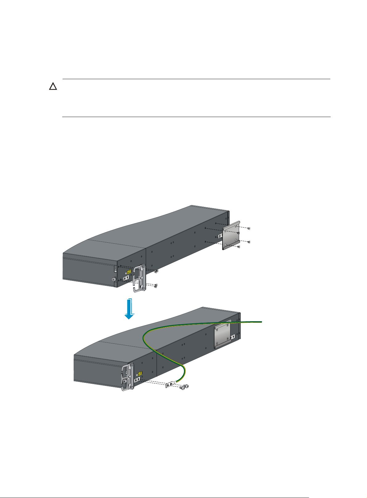
Use M4 screws (supplied with the switch) to fix the chassis rails to the chassis.
4.
Attach the mounting brackets and chassis rails to both sides of the chassis in the same way.
Connecting the grounding cable to the switch chassis
CAUTION:
The primary grounding point and auxiliary grounding point are located on the left side panel. If you use
either of the grounding points, you must connect the grounding cable to the grounding point before you
mount the switch in the rack.
To connect the grounding cable to a chassis grounding point, for example, the primary grounding point:
1. Select a grounding point.
2. Unpack the grounding cable and the grounding screws. (You can use the cable and screws for
connecting to the primary grounding point or the auxiliary grounding point.)
3. Align the two-hole grounding lug at one end of the cable with the grounding holes of the
grounding point, insert the grounding screws into the holes, and tighten the screws with a
screwdriver to fix the grounding lug to the chassis, as shown in Figure 17.
Figure 17 Attaching the rear mounting brackets, chassis rails, and the grounding cable to the chassis
14
Page 21

Figure 18 Attaching the front mounting brackets and the chassis rails to the chassis
Rack-mounting the S5830-52SC switch
Attaching the slide rails to the rack
1. Identify the rack attachment position for the slide rails.
2. Install cage nuts (user-supplied) in the mounting holes in the rack posts.
3. Align the screw holes in one slide rail with the cage nuts in the rack post on one side, and use
screws (user supplied) to fix the slide rail to the rack, as shown in Figure 19.
4. Repeat the preceding step to attach the other slide rail to the rack post on the other side. Keep the
two slide rails at the same height so the slide rails can fix into the chassis rails.
Figure 19 Installing the slide rails
Installing the switch in the rack
This task requires two persons.
To install the switch in the rack:
15
Page 22

Wear an ESD-preventive wrist strap and make sure it makes good skin contact and is well
1.
grounded.
2. Verify that the mounting brackets and chassis rails have been securely fixed on the two sides of the
switch (see "Installing the mounting brackets, chassis rails, and grounding cable (for the
S5830-52SC)").
3. Verify that the slide rails have been correctly attached to the rack posts (see "Attaching the slide
rails to the rack").
4. Install cage nuts (user-supplied) to the front rack posts and make sure they are at the same level as
the slide rails.
5. Supporting the bottom of the switch, align the chassis rails with the slide rails on the rack posts, as
shown in Figure 20. Work with another person to slide the chassis rails along the slide rails until
the mounting brackets flush with the rack posts.
6. Use appropriate screws to fix the mounting brackets to the rack, as shown in Figure 21.
Figure 20 Installing the switch in the rack (I)
16
Page 23

Figure 21 Installing the switch in the rack (II)
IMPORTANT:
To ensure steadiness of the switch in the rack, make sure the front ends of the slide rails reach
chassis rails, as shown in callout 1 in Figure 21.
Rack-mounting the S5830-106S switch
Attaching the slide rails to the rack
1. Identify the rack attachment position for the slide rails.
2. Install cage nuts (user-supplied) in the mounting holes in the rack posts.
3. Align the screw holes in one slide rail with the cage nuts in the rack post on one side, and use
screws (user supplied) to fix the slide rail to the rack, as shown in Figure 22.
4. Repeat the preceding steps to attach the other slide rail to the rack post on the other side. Keep the
two slide rails at the same height so the slide rails can fix into the chassis rails.
out of the
17
Page 24

Figure 22 Installing the slide rails
Installing the switch in the rack
This task requires two persons.
To install the switch in the rack:
1. Wear an ESD-preventive wrist strap and make sure it makes good skin contact and is well
grounded.
2. Verify that the mounting brackets and chassis rails have been securely fixed on the two sides of the
switch (see "Installing the mounting brackets, chassis rails, and grounding cable (for the
S5830-106S)").
3. Verify that the slide rails have been correctly attached to the rack posts (see "Attaching the slide
rails to the rack").
4. Install cage nuts (user-supplied) to the front rack posts and make sure they are at the same level as
the slide rails.
5. Supporting the bottom of the switch, align the chassis rails with the slide rails on the rack posts, as
shown in Figure 23. Work with another person to slide the chassis rails along the slide rails until
the mounting brackets flush with the rack posts.
6. Use appropriate screws to fix the mounting brackets to the rack, as shown in Figure 24.
18
Page 25

Figure 23 Installing the switch in the rack (I)
Figure 24 Installing the switch in the rack (II)
IMPORTANT:
To ensure steadiness of the switch in the rack, make sure the front ends of the slide rails reach
out of the
chassis rails, as shown in callout 1 in Figure 24.
19
Page 26

Grounding the switch
WARNING!
Correctly connecting the switch grounding cable is crucial to lightning protection and EMI protection.
NOTE:
The power and grounding terminals in this section are for illustration only.
The power input end of the switch has a noise filter, whose central ground is directly connected to the
chassis to form the chassis ground (commonly known as PGND). You must securely connect this chassis
ground to the earth so the faradism and leakage electricity can be safely released to the earth to
minimize EMI susceptibility of the switch.
You can ground the switch in one of the following ways, depending on the grounding conditions
available at the installation site:
• Grounding the switch with a grounding strip
• Grounding the switch through the PE wire of an AC power cord
Grounding the switch with a grounding strip
1. Attach the two-hole grounding lug at one end of the grounding cable to a grounding point on the
switch chassis (see "Connecting the grounding cable to the switch chassis").
2. Connect the OT terminal at the other end of the grounding cable to a grounding post on the
grounding strip, and fasten the grounding cable to the grounding post with a hex nut.
Figure 25 Connecting the grounding cable to a grounding strip
(1) Hex nut (2) OT terminal
(3) Grounding post (4) Grounding strip
20
Page 27

for
Grounding the switch through the PE wire of an AC power cord
If you ground an AC-powered switch through the protective earth (PE) wire of the power cord, verify that
the following conditions are met:
• The power cord is a three-wire power cord that provides a PE terminal.
• The ground contact in the power outlet is well connected to the ground in the power distribution
room or on the AC transformer side.
• The power cord is securely connected to the power outlet.
Figure 26 Grounding through the PE wire of an AC power cord
Installing/removing a fan tray
CAUTION:
The S5830 switches have only one fan tray slot. To ensure good ventilation, follow these guidelines:
• Do not operate the switch without a fan tray.
• If the fan tray has problems during operation, replace it within 8 minutes while the switch is operating
the LSVM152SCFAN and LSVM252SCFAN, and 6 minutes for the LSVM1106SFAN and
LSVM2106SFAN. Otherwise, the switch generates alarms and the system LED flashes red, or the switch
may even be damaged.
Selecting a fan tray
The S5830 switches provide two types of fan trays with different airflow directions: from power side to
port side and from port side to power side. Before you install a fan tray, check the airflow direction
labeled on the fan tray and make sure the airflow of the chassis is appropriate to the installation site.
When the switch is started up, the system records the airflow direction of the fan tray. After you replace
the fan tray when the switch is operating, if the airflow direction of the new fan tray is not the same as
the old one, the system displays the following trap and log information:
System fan airflow direction is not preferred on slot x, please check it.
If you confirm that the airflow direction of the new fan tray is correct, use the fan prefer-direction slot
slot-number { power-to-port | port-to-power } command in system view to change the preferred airflow
direction.
For more information about the cooling system and fan tray specifications of the switch, see "Cooling
system" and "Hot swappable fan trays."
21
Page 28

For more information about the fan prefer-direction slot command, see H3C S5830 Switch Series
Fundamentals Command Reference.
Installing a fan tray
CAUTION:
To prevent damage to the fan tray or the connectors on the backplane, insert the fan tray gently. If you
encounter a hard resistance while inserting the fan tray, pull out the fan tray and insert it again.
To install a fan tray:
1. Wear an ESD-preventive wrist strap and make sure it makes good skin contact and is well
grounded.
2. Loosen the captive screws on the filler panel to remove the filler panel.
3. Unpack the fan tray and verify that the fan tray model is correct.
4. Grasp the handle of the fan tray with one hand and support the fan tray bottom with the other, and
slide the fan tray along the guide rails into the slot until the fan tray seats in the slot and has a firm
contact with the backplane (see callout 1 in Figure 27 or Figure 28).
5. Fasten the captive screw on the fan tray with a Philips screwdriver until the fan tray is securely fixed
into the chassis (see callout 2 in Figure 27 or Figure 28).
If the captive screw cannot be tightly attached, examine the installation of the fan tray.
Figure 27 Installing an LSVM152SCFAN or LSVM252SCFAN fan tray
22
Page 29

Figure 28 Installing an LSVM1106SFAN or LSVM2106SFAN fan tray
Removing a fan tray
WARNING!
Take out the fan tray after the fans completely stop rotating. Do not touch the fans even if the fans stop
rotating to avoid affecting fan balance, which might cause loud fan operating noise.
To remove a fan tray:
1. Wear an ESD-preventive wrist strap and make sure it makes good skin contact and is well
grounded.
2. Loosen the captive screw of the fan tray with a Philips screwdriver until it is fully disengaged from
the switch chassis.
3. Grasp the handle of the fan tray with one hand and pull the fan tray part way out the slot. Support
the fan tray bottom with the other hand, and pull the fan tray slowly along the guide rails out of the
slot.
Put the removed fan tray in an antistatic bag.
Installing/removing a power module
The S5830 switch comes with both power module slots covered by a filler panel. You can install one or
two power modules for these switches as needed. For more information about the power modules
available for the switches, see "Appendix B FRUs and compatibility matrixes."
Installing/removing a power module
Installing a power module
23
Page 30

g
t
CAUTION:
• Follow the forward inertia of the power module when inserting it into the chassis to make sure
the power
module has firm contact with the connectors on the backplane.
• To prevent damage to the connectors inside the switch chassis, insert the power module gently. If you
encounter a hard resistance while insertin
the power module, pull out the power module and insert i
again.
To install a power module:
1. Wear an ESD-preventive wrist strap and make sure it makes good skin contact and is well
grounded.
2. Remove the filler panel on the target power module slot.
3. Unpack the power module and verify that the power module model is correct.
4. Correctly orient the power module with the power module slot (see Figure 29 and Figure 30),
grasp the handle of the module with one hand and support the module bottom with the other, and
slide the module slowly along the guide rails into the slot. The slot is foolproof. If you cannot insert
the power module into the slot, re-orient the power module rather than use excessive force to push
it in.
Figure 29 Installing a power module (S5830-52SC)
Figure 30 Installing a power module (S5830-106S)
Removing a power module
CAUTION:
If the switch has two power modules, removing one power module does not affect the operation of the
switch. If the switch has only one power module, removing the power module powers off the switch.
24
Page 31

To remove a power module:
1. Wear an ESD-preventive wrist strap and make sure it makes good skin contact and is well
grounded.
2. Remove the power cord from the power module. When removing the DC power cord, squeeze the
tabs on the power cord connector with your thumb and forefinger and then pull the connector out,
as shown in Figure 31.
3. Hold the handle on the power module with one hand, pivot the latch on the power module with
your thumb, and pull the power module part way out of the slot. Then supporting the power module
bottom with one hand, slowly pull the power module out with the other hand, as shown in Figure
32 and Figure 33.
Put the removed power module in an antistatic bag.
Install a filler panel if no power module is to be installed.
Figure 31 Removing the DC power cord
(1) Press the tabs on the power cord connector with your thumb
and forefinger
(2) Pull the power cord connector out
Figure 32 Removing the power module (S5830-52SC)
(1) Pivot the latch to the right with your thumb (2) Pull the power module out
25
Page 32

Figure 33 Removing the power module (S5830-106S)
(1) Pivot the latch up with your thumb (2) Pull the power module out
Connecting the power cord
Connecting the AC power cord
1. Insert the female connector of the AC power cord supplied with the power module into the
AC-input power receptacle of the power module.
2. Use a cable tie to secure the power cord to the handle of the power module, as shown in Figure
34.
3. Connect the other end of the power cord to an AC power outlet.
Figure 34 Connecting the AC power cord
(1) Cable tie
(2) Tighten the cable tie to secure the power cord to the handle of the power module
Connecting the DC power cord
1. Unpack the DC power cord, identify the plug for connecting to the power module, orient the plug
with the power receptacle on the power module, and insert the plug into the receptacle (see Figure
26
Page 33

35). The receptacle is foolproof. If you cannot insert the plug into the receptacle, re-orient the plug
rather than use excessive force to push it in.
2. Use a cable tie to secure the power cord to the handle of the power module, as shown in Figure
34.
3. Connect the other end of the power cord to the DC power source.
Figure 35 Connecting the DC power cord
Installing/removing an interface card
The S5830-52SC switch provides an expansion interface slot covered with a filler panel. For the interface
card available for the switch, see "Appendix B FRUs and compatibility matrixes."
Installing an interface card
1. Wear an ESD-preventive wrist strap, ensure a good skin contact and make sure the ESD-preventive
wrist strap is properly grounded.
2. Loosen the mounting screws on the filler panel over the interface card slot at the front panel with a
Phillips screwdriver and remove the filler panel.
Put away the removed filler panel for future use.
Figure 36 Removing the filler panel over an interface card slot
3. Unpack the interface card. Squeezing the mounting screws on the interface card, gently push the
interface card in along the slot guide rails until the interface card has close contact with the switch.
4. Tighten the captive screws with a Phillips screwdriver to fix the interface card.
27
Page 34
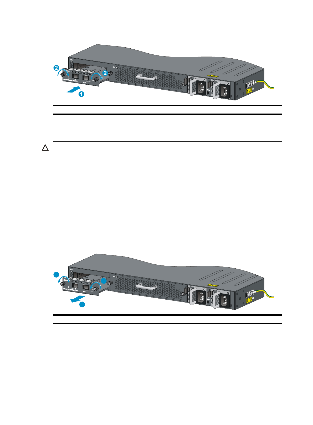
Figure 37 Installing an interface card
(1) Slide the interface card into the slot (2) Tighten the captive screws
Removing an interface card
CAUTION:
• Do not touch the surface-mounted components directly with your hands.
• Do not use excessive force in the operation.
To remove an interface card:
1. Wear an ESD-preventive wrist strap, ensure a good skin contact and make sure the ESD-preventive
wrist strap is properly grounded.
2. Use a Phillips screwdriver to loosen the captive screws at both sides of the interface card until all
spring pressure is released.
3. Pull the interface card along the guide rails until it completely comes out of the switch chassis.
If no new card is to be ins talle d after you remove an interface card, install the filler panel to prevent
dust and ensure good ventilation in the switch.
Figure 38 Removing an interface card
1
1
2
(1) Loosen the captive screws (2) Pull the interface card out of the slot
Verifying the installation
Before powering on the switch, verify that:
• There is enough space for heat dissipation around the switch, and the rack is stable.
• The grounding cable is securely connected.
• The correct power source is used.
28
Page 35

• The power cords are properly connected.
29
Page 36

Powering on the switch for the first time
Setting up the configuration environment
To set up the configuration environment, connect a terminal (a PC in this example) to the console port on
the switch with a console cable.
Figure 39 Setting up the configuration environment
Connecting the console cable
Console cable
A console cable is an 8-core shielded cable, with a crimped RJ-45 connector at one end for connecting
to the console port of the switch, and a DB-9 female connector at the other end for connecting to the
serial port on the console terminal.
Figure 40 Console cable
A side
Pos.9
A
Pos.1
Main label
8
1
B side
B
Connection procedure
When you connect the console cable, follow these guidelines:
• Identify the mark on the console port to make sure you are connecting to the correct port.
30
Page 37

• The serial port on a PC does not support hot swapping. When you connect a PC to a powered-on
switch, connect the DB-9 connector of the console cable to the PC before connecting the RJ-45
connector to the switch.
• When you disconnect a PC from a powered-on switch, Disconnect the DB-9 connector of the console
cable from the PC after disconnecting the RJ-45 connector from the switch.
Use a console cable to connect a terminal device to the switch, as follows:
1. Plug the DB-9 female connector to the serial port of the console terminal or PC.
2. Connect the RJ-45 connector to the console port of the switch.
Setting terminal parameters
To configure and manage the switch, you must run a terminal emulator program on the console terminal,
for example, a PC. This section uses Windows XP HyperTerminal as an example.
The following are the required terminal settings:
• Bits per second—9,600
• Data bits—8
• Parity—None
• Stop bits—1
• Flow control—None
• Emulation—VT100
To set terminal parameters, for example, on a Windows XP HyperTerminal:
1. Select Start > All Programs > Accessories > Communications > HyperTerminal.
The Connection Description dialog box appears.
2. Enter the name of the new connection in the Name field and click OK.
Figure 41 Connection description
3. Select the serial port to be used from the Connect using list, and click OK.
31
Page 38

Figure 42 Setting the serial port used by the HyperTerminal connection
4. Set Bits per second to 9600, Data bits to 8, Parity to None, Stop bits to 1, and Flow control to None,
and click OK.
Figure 43 Setting the serial port parameters
5. Select File > Properties in the HyperTerminal window.
32
Page 39

Figure 44 HyperTerminal window
6. On the Settings tab, set the emulation to VT100 and click OK.
Figure 45 Setting terminal emulation in Switch Properties dialog box
33
Page 40

Powering on the switch
Before powering on the switch, verify that:
• The power cord is properly connected.
• The input power voltage meets the requirement of the switch.
• The console cable is properly connected, the terminal or PC used for configuration has started, and
the configuration parameters have been set.
Power on the switch. During the startup process, you can access the BootWare menu to perform tasks
such as software upgrade and file management. The BootWare menu output and options differ with
software versions. For more information about BootWare menu options, see the software-matching
release notes for the device.
After the startup completes, you can access the CLI to configure the switch.
For more information about the configuration commands and CLI, see H3C S5830 Switch Series
Configuration Guides and H3C S5830 Switch Series Command References.
34
Page 41

Setting up an IRF fabric
You can use H3C Intelligent Resilient Framework (IRF) technology to connect and virtualize S5830
switches into a virtual switch called an "IRF fabric" or "IRF virtual device" for flattened network topology,
and high availability, scalability, and manageability.
IRF fabric setup flowchart
Figure 46 IRF fabric setup flowchart
Start
Plan IRF fabric setup
Install IRF member switches
Connect the grounding cable
and power cords
Power on the switches
Configure basic IRF settings
Connect the physical IRF ports
Slave switches reboot and the
IRF fabric is automatically
established
End
To set up an IRF fabric:
35
Page 42

Step Description
Plan the installation site and IRF fabric setup parameters. Complete the
following tasks:
• Planning IRF fabric size and the installation site
1. Plan IRF fabric setup.
• Identifying the master switch and planning IRF member IDs
• Planning IRF topology and connections
• Identifying physical IRF ports on the member switches
• Planning the cabling scheme
2. Install IRF member
switches.
3. Connect ground wires
and power cords.
See "Installing the switch in a 19-inch rack."
See "Grounding the switch" and "Connecting the power cord."
4. Power on the switches.
5. Configure basic IRF
settings.
6. Connect the physical
IRF ports.
N/A
For more information about IRF, see H3C S5830 Switch Series IRF
Configuration Guide.
Connect the physical IRF ports on the switches. Use SFP+ transceiver modules
and fibers to connect 10-Gigabit SFP+ ports over a long distance, or use SFP+
cables to connect 10-Gigabit SFP+ ports over a short distance.
All switches except the master switch automatically reboot, and the IRF fabric is
established.
Planning IRF fabric setup
Planning IRF fabric size and the installation site
Choose S5830 switch models and identify the number of required IRF member switches, depending on
the user density and upstream bandwidth requirements. The switching capacity of an IRF fabric equals
the total switching capacities of all member switches.
Plan the installation site depending on your network solution, as follows:
• Place all IRF member switches in one rack for centralized high-density access.
• Distribute the IRF member switches in different racks to implement the top-of-rack (ToR) access
solution for a data center.
NOTE:
To increase the switching capacity without any topology change or replacement, you can plug an S5830
switch into an IRF fabric.
Identifying the master switch and planning IRF member IDs
Determine which switch you want to use as t he master for ma na ging all member switches in t he IRF fabric.
An IRF fabric has only one master switch. You configure and manage all member switches in the IRF
fabric at the command line interface of the master switch.
36
Page 43

C
NOTE:
IRF member switches will automatically elect a master. You can affect the election result by assigning a
high member priority to the intended master switch. For more information about master election, see
S5830 Switch Series IRF Configuration Guide
.
Prepare an IRF member ID assignment scheme. An IRF fabric uses member IDs to uniquely identify and
manage its members, and you must assign each IRF member switch a unique member ID.
Planning IRF topology and connections
You can create an IRF fabric in daisy chain topology, or more reliably, ring topology. In ring topology,
the failure of one IRF link does not cause the IRF fabric to split as in daisy chain topology. Rather, the IRF
fabric changes to a daisy chain topology without interrupting network services.
You connect the IRF member switches through IRF ports, the logical interfaces for the connections
between IRF member switches. Each IRF member switch has two IRF ports: IRF-port 1 and IRF-port 2. An
IRF port is activated when you bind a physical port to it.
When connecting IRF member switches, you must connect the physical ports of IRF-port 1 on one switch
to the physical ports of IRF-port 2 on its neighbor switch.
The S5830 switches can provide 10-GE IRF connections through SFP+ ports, and you can bind several
SFP+ ports to an IRF port for increased bandwidth and availability.
H3
NOTE:
Figure 47 and Figure 48 show the topologies for an IRF fabric made up of three S5830-52SC switches for
IRF connections. The IRF port connections in the
two figures are for illustration only, and more connection
methods are available.
Figure 47 IRF fabric in daisy chain topology
37
Page 44

Figure 48 IRF fabric in ring topology
Identifying physical IRF ports on the member switches
Identify the physical IRF ports on the member switches according to your topology and connection
scheme.
Table 6 shows the physical ports that can be used for IRF connection.
Table 6 Physical IRF port requirements
Switch chassis Candidate physical IRF ports
• 2 fixed SFP+ ports on the front panel
• 2 SFP+ ports on the 10 GE SFP+ expansion interface card at the rear panel
S5830-52SC
S5830-106S 10 fixed SFP+ ports on the front panel
NOTE:
You must purchase the expansion interface card separately.
Planning the cabling scheme
Use SFP+ cables or SFP+ transceivers and fibers to connect the IRF member switches. If the IRF member
switches are far away from one another, choose the SFP+ transceiver modules with optical fibers. If the
IRF member switches are all in one equipment room, choose SFP+ cables.
Table 7 lists the SFP+ transceivers and SFP+ cables available for IRF connections.
Table 7 SFP+ transceiver modules and SFP+ cables available for IRF connections
Transceiver/cable
Central
wavelength
Connector Cable Max transmission distance
10 GE SFP+ transceivers
50/125 μm
SFP-XG-SX-MM850-A 850 nm LC
38
multi-mode
optical fiber
300 m (984.3 ft)
Page 45

t
Transceiver/cable
SFP-XG-LX220-MM1310 1310 nm LC
SFP-XG-LX-SM1310 1310 nm LC
Central
wavelength
Connector Cable Max transmission distance
62.5/125 μm
multi-mode
optical fiber
9/125 μm
single-mode
optical fiber
220 m (721.8 ft)
10 km (6.21 miles)
10 GE SFP+ cables
LSWM1STK N/A N/A SFP+ cable 0.65 m (2.1 ft)
LSWM2STK N/A N/A SFP+ cable 1.2 m (3.9 ft)
LSWM3STK N/A N/A SFP+ cable 3 m (9.8 ft)
LSTM1STK N/A N/A SFP+ cable 5 m (16.4 ft)
LSTM2STK N/A N/A SFP+ cable 7 m (22.97 ft)
The following subsections describe several H3C recommended IRF connection schemes. All these
schemes use a ring topology.
IMPORTANT:
In these schemes, all physical IRF ports are located on the same side. If physical IRF ports are on differen
sides, you must measure the distance between them to select an appropriate cable.
Connecting the IRF member switches in one rack
Use short-haul and long-haul SFP+ cables to connect the IRF member switches (four switches in this
example) in a rack as shown in Figure 49. The switches in the ring topology (see Figure 51) are in the
same order as connected in the rack.
Figure 49 Connecting the switches in one rack (Method 1)
39
Page 46

Figure 50 Connecting the switches in one rack (Method 2)
Figure 51 IRF fabric topology
Connecting the IRF member switches in a ToR solution
You can install IRF member switches in different racks side by side to deploy a top of rack (ToR) solution.
Figure 52 shows an example for connecting four top of rack IRF member switches by using SFP+
transceiver modules and optical fibers. The topology is the same as Figure 51.
Figure 52 Connecting top of rack switches
Configuring basic IRF settings
After you install the IRF member switches, power on the switches, and log in to each IRF member switch
(see H3C S5830 Switch Series Fundamentals Configuration Guide) to configure their member IDs,
member priorities, and IRF port bindings.
Follow these guidelines when you configure the switches:
• Assign the master switch higher member priority than any other switch.
• Bind physical ports to IRF port 1 on one switch and to IRF port 2 on the other switch. You perform IRF
port binding before or after connecting IRF physical ports depending on the software release.
• To bind the ports on an interface card to an IRF port, you must install the interface card first. For how
to install an interface card, see H3C LSPM2SP2P Interface Card User Manual.
• Execute the display irf configuration command to verify the basic IRF settings.
For more information about configuring basic IRF settings, see H3C S5830 Switch Series IRF
Configuration Guide.
40
Page 47

Connecting the physical IRF ports
CAUTION:
Wear an ESD-preventive wrist strap when you connect SFP+ cables or SFP+ transceiver modules and
fibers. For how to connect them, see
Guide
.
H3C Pluggable SFP/SFP+/XFP Transceiver Modules Installation
Connect IRF member switches with SFP+ cables or SFP+ transceivers and fibers as planned.
Accessing the IRF fabric to verify the configuration
To verify the basic functionality of the IRF fabric when you are finished configuring basic IRF settings and
connecting IRF ports:
1. Log in to the IRF fabric through the console port of any member switch.
2. Create a Layer 3 interface, assign it an IP address, and make sure the IRF fabric and the remote
network management station can reach each other.
3. Use Telnet, web or SNMP to access the IRF fabric from the network management station. (See H3C
S5830 Switch Series Fundamentals Configuration Guide.)
4. Verify that you can manage all member switches as if they were one node.
5. Display the running status of the IRF fabric by using the commands in Table 8.
Table 8 Displaying and maintaining IRF configuration and running status
Task Command
Display information about the IRF fabric. display irf
Display all members' configurations. display irf configuration
Display topology information about the IRF
fabric.
display irf topology
NOTE:
To avoid IP address collision and network problems, configure at least one multi-active detection (MAD)
mechanism to detect the presence of multiple identical IRF fabrics and handle collisions. For more
information about MAD detection, see
H3C S5830 Switch Series IRF Configuration Guide
.
41
Page 48

Maintenance and troubleshooting
Power module failure
When a power module is operating properly, its status LED is green. If not, follow these steps to
troubleshoot the power module:
1. Check for an over-temperature condition. Over-temperature can cause a power module to enter
the protection state. Make sure the switch is well ventilated.
2. Check for loose power cord connection, and reconnect the power cord. If the power cord is
broken, replace it.
3. Verify that the power module is fully seated in the slot.
4. Verify that the power source is normally supplying power at the correct voltage.
5. If the other power module slot is empty, plug the power module into the empty slot to check for an
operating anomaly.
6. Plug a new power module of the same model into the same slot, and connect it to the same power
input end. If the new power module can work properly, the old power module has failed. Contact
the H3C local agent to replace the old power module.
Fan failure
When a fan tray is operating properly, its status LED is green. If the LED is red or off, follow these steps
to troubleshoot the fan tray:
1. Verify that the switch and the power modules are operating properly.
2. Verify that the air intakes and exhaust vents of the chassis are not blocked.
If the problem persists, contact the H3C local agent or technical support engineer for help.
Configuration terminal problems
If the configuration environment setup is correct, the configuration terminal displays boot information
when the switch is powered on. If the setup is incorrect, the configuration terminal displays nothing or
garbled text.
No terminal display
If the configuration terminal displays nothing when the switch is powered on, verify the following items:
• The power supply is supplying power to the switch.
• The console cable is properly connected.
• The console cable has no problem and the terminal settings are correct.
Garbled terminal display
If terminal display is garbled, verify that the following settings are configured for the terminal, for
example, HyperTerminal:
• Baud rate—9,600
42
Page 49

• Data bits—8
• Parity—None
• Stop bits—1
• Flow control—None
• Emulation—VT100
43
Page 50

Appendix A Technical specifications
Technical specifications
Table 9 H3C S5830 Switch Series technical specifications
Item S5830-52SC S5830-106S
Dimensions (H × W × D)
Weight < 10 kg (22.05 lb) < 20 kg (44.09 lb)
Console ports 1 1
Management Ethernet ports 1 1
10/100/1000 Base-T
auto-sensing Ethernet ports
1000Base-X SFP ports 2 N/A
SFP+ ports 2 10
Expansion interface card
slots
Fan tray slots 1, on the rear panel 1, on the rear panel
Power module slots 2, on the rear panel 2, on the rear panel
Input
voltage
Total
power
consumpti
on
AC
DC Rated voltage: –40 VDC to –60 VDC
Static Minimum: 91.2 W Minimum: 283.5 W
Full
configuration
43.6 × 440 × 460 mm (1.72 ×
17.32 × 18.11 in)
48 96
1, on the rear panel N/A
Rated voltage: 100 VAC to 240
VAC @ 50 Hz or 60 Hz
Maximum: 128.6 W Maximum: 380 W
86 × 440 × 700 mm (3.39 × 17.32 ×
27.56 in)
Rated voltage: 100 VAC to 240 VAC @
50 Hz or 60 Hz
Rated voltage: –40 VDC to –60 VDC
Fan power consumption 0.9 W to 8.4 W 4.4 W to 75.5 W
Chassis leakage current UL60950-1/EN60950-1/IEC60950-1/GB4943
Melting
current of
power
module fuse
Operating temperature 0°C to 45°C (32°F to 113°F)
Operating humidity 5% to 95%, noncondensing
Fire prevention
requirements
AC-input 10A/250V 10A/250V
DC-input 30A/250V 30A/250V
UL60950-1/EN60950-1/IEC60950-1/GB4943
44
Page 51

Cooling system
The cooling system of the S5830 switch comprises the air vents in the chassis, fan tray, and built-in fans
of power modules. To guarantee the performance of this cooling system, you must consider the
ventilation design for the installation site when you choose a fan tray assembly and plan the installation
site for the S5830 switch.
Cooling system of the S5830-52SC
• When an LSVM152SCFAN fan tray is used, ambient air flows in through the air vents in the fan tray
panel and the power module panels, circulates through the chassis and the power modules, and
exhausts at the port side, as shown in Figure 53.
• When an LSVM252SCFAN fan tray is used, ambient air flows in through the air vents in the
port-side panel and the power module panels, circulates through the chassis and the power
modules, and exhausts through the air vents in the fan tray panel, as shown in Figure 54.
Figure 53 Airflow through the S5830-52SC chassis (with the LSVM152SCFAN fan tray)
1
Port side
3
(1) Power module air vents (2) Fan tray air vents
(3) Port side air vents
1
Power side
2
45
Page 52

Figure 54 Airflow through the S5830-52SC chassis (with the LSVM252SCFAN fan tray)
(1) Power module air vents (2) Fan tray air vents
(3) Port-side air vents
IMPORTANT:
The chassis and the power modules use separate air aisles. Make sure both aisles are not blocked.
Cooling system of the S5830-106S
• When an LSVM1106SFAN fan tray is used, ambient air flows in through the air vents in the fan tray
panel and the power module panels, circulates through the chassis and the power modules, and
exhausts at the port side, as shown in Figure 55.
• When an LSVM2106SFAN fan tray is used, ambient air flows in through the air vents in the port-side
panel and the power module panels, circulates through the chassis and the power modules, and
exhausts through the air vents in the fan tray panel, as shown in Figure 56.
46
Page 53

Figure 55 Airflow through the S5830-106S chassis (with the LSVM1106SFAN fan tray)
2
Power side
Port side
1
1
3
(1) Power module air vents (2) Fan tray air vents
(3) Port side air vents
Figure 56 Airflow through the S5830-106S chassis (with the LSVM2106SFAN fan tray)
(1) Power module air vents (2) Fan tray air vents
(3) Port-side air vents
47
Page 54

Appendix B FRUs and compatibility matrixes
Hardware compatibility matrix
Interface cards, power modules, and fan trays are field replaceable units (FRUs) and must be purchased
separately. When you purchase or install these FRUs, use Table 10 to verify that they are compatible with
the switch.
Table 10 FRU compatibility matrix
Card/module S5830-52SC S5830-106S
Hot swappable power module options
LSVM1AC650 Yes Yes
LSVM1DC650 Yes Yes
LSVM1AC300 Yes No
LSVM1DC300 Yes No
Hot swappable fan tray options
LSVM152SCFAN Yes No
LSVM252SCFAN Yes No
LSVM1106SFAN No Yes
LSVM2106SFAN No Yes
Interface card options
LSPM2SP2P Yes No
Hot swappable power modules
Every S5830 switch has two power module slots. You can install one power module, or for redundancy,
two power modules in Table 11 for an S5830 switch. All these power modules are hot swappable.
IMPORTANT:
H3C recommends that you use power modules of the same model on the same switch.
Table 11 Power module specifications and the compatibility with the H3C S5830 Switch Series
Power module Specifications Switch chassis Reference
• Rated input voltage range:
100 VAC to 240 VAC @ 50 Hz or 60
Hz
LSVM1AC650
• Max input voltage range:
90 VAC to 264 VAC @ 47 Hz or 63 Hz
• Max output power:
650 W
S5830-52SC
S5830-106S
H3C LSVM1AC650 &
LSVM1DC650 Power
Modules User Manual
48
Page 55

Power module Specifications Switch chassis Reference
• Rated input voltage range:
LSVM1DC650
–40 VDC to –60 VDC
• Max input voltage range:
–40 VDC to –72 VDC
• Max output power:
650 W
S5830-52SC
S5830-106S
H3C LSVM1AC650 &
LSVM1DC650 Power
Modules User Manual
• Rated input voltage range:
100 VAC to 240 VAC @ 50 Hz or 60
LSVM1AC300
Hz
• Max input voltage range:
85 VAC to 264 VAC @ 47 Hz or 63 Hz
S5830-52SC
H3C LSVM1AC300 &
LSVM1DC300 Power
Modules User Manual
• Max output power:
315 W
• Rated input voltage range:
LSVM1DC300
–48 VDC to –60 VDC
• Max input voltage range:
–36 VDC to –72 VDC
• Max output power:
315 W
S5830-52SC
H3C LSVM1AC300 &
LSVM1DC300 Power
Modules User Manual
Hot swappable fan trays
The S5830 switches use hot swappable fan trays for heat dissipation. Table 12 describes the fan trays
available for these switches.
Table 12 Fan tray specifications
Item Specifications
LSVM152SCFAN (S5830-52SC)
Fans Four 40 × 40 × 28 mm (1.57 × 1.57 × 1.1 in) fans
Max fan speed 9500 R.P.M
Max airflow 40 cubic feet per minute (CFM)
Airflow direction Rear to front (fans blow air from the power side to the port side.)
Max power
consumption
Min power
consumption
Documentation
reference
LSVM252SCFAN (S5830-52SC)
Fans Four 40 × 40 × 28 mm (1.57 × 1.57 × 1.1 in) fans
8.42 W
0.87 W
H3C LSVM152SCFAN & LSVM252SCFAN Fan Modules User Manual
Max fan speed 9500 R.P.M
Max airflow 40 CFM
49
Page 56

Item Specifications
Airflow direction ar (fans draw air from the port side to the power side.) Front to re
Max power
consumption
Min power
consumption
Documentation
reference
8.42 W
0.87 W
H3C LSVM152
SCFAN & LSVM252SCFAN Fan Modules User Manual
LSVM1106SFAN (S5830-106S)
Fans Five 60 × 60 × 38 mm (2.36 × 2.36 × 1.50 in) fans
Max fan speed M 11000 R.P.
Max airflow 135 CFM
Airflow direction ont (fans blow air from the power side to the port side.) Rear to fr
Max power
consumption
Min power
consumption
Documentation
reference
75.5 W
4.4 W
H3C LSVM1106SFAN & LSVM2106SFAN Fan Modules User Manual
LSVM2106SFAN (S5830-106S)
Fans Five 60 × 60 × 38 mm (2.36 × 2.36 × 1.50 in) fans
Fan speed 11000 R.P.M
Max airflow 135 CFM
Airflow direction ar (fans draw air from the port side to the power side.) Front to re
Max power
consumption
Min power
consumption
Documentation
reference
Interface cards
Table 13 describes t
interface card slot.
able 13 S583 2SC inte
T 0-5 rface card
Card model Name Description
LSPM2SP2P 2-port 10 GE SFP+ optical interface card
he interface card available for the S5830-52SC switch that has one expansion
75.5 W
4.4 W
H3C LSVM1106SFAN & LSVM2106SFAN Fan Modules User Manual
es two 1-/10- Gbps SFP+ fiber
Provid
ports
For more information about the interface card, see H3C LSPM2SP2P Interface Card User Manual.
50
Page 57

Appendix C Ports and LEDs
Ports
Console port
Every S5830 switch has one console port.
Table 14 Console port specifications
Item Specification
Connector type
Compliant standard
Transmission baud rate 9600 bps (default) to 115200 bps
Services
RJ-45
EIA/TIA-232
• Provides connection to an ASCII terminal.
• Provides connection to the serial port of a local PC running terminal emulation
program.
Management Ethernet port
Every S5830 switch has a management Ethernet port. You can connect this port to a PC or management
station for loading and debugging system software or remote management.
Table 15 Management Ethernet port specifications
Item Specification
Connector type RJ-45
Connector quantity 1
Port transmission rate 10/100/1000 Mbps, half/full duplex
Transmission medium and
max transmission
distance
100 m (328.08 ft) over category-5 twisted pair cable
Functions and services Switch software and Boot ROM upgrade, network management
10/100/1000Base-T Ethernet port
Every S5830 switch has 10/100/1000Base-T Ethernet ports.
Table 16 10/100/1000Base-T Ethernet port specifications
Item Specification
Connector type
RJ-45
51
Page 58

Item Specification
• 10 Mbps, full duplex
Interface attributes
• 100 Mbps, full duplex
• 1000 Mbps, full duplex
• MDI/MDI-X, auto-sensing
Max transmission
distance
Transmission medium
Standards
SFP port
The S5830-52SC switch has two GE SFP ports, and yo u c an ins ta ll t he 100 Mbp s or 100 0 M bps SF P
transceiver modules in Table 17 in the ports.
Table 17 SFP transceiver modules available for the S5830-52SC switch
Transceiver module
1000 Mbps transceiver modules
SFP-GE-SX-MM850-A 850 nm LC
100 m (328.08 ft)
Category-5 (or above) twisted pair cable
IEEE 802.3i, 802.3u, and 802.3ab
Central
wavelength
Connector
Fiber
• 50/125 μm
multi-mode
optical fiber
• 62.5/125 μm
multi-mode
optical fiber
Max transmission
distance
• 550 m (1804.46 ft)
over 50/125 μm
fiber
• 275 m (902.23 ft)
over 62.5/125 μm
fiber
SFP-GE-LX-SM1310-A 1310 nm LC
SFP-GE-LH40-SM1310 1310 nm LC
SFP-GE-LH40-SM1550 1550 nm LC
SFP-GE-LH70-SM1550 1550 nm LC
SFP-GE-LH100-SM1550 1550 nm LC
SFP-GE-LH70-SM1470-C
W
SFP-GE-LH70-SM1490-C
W
1470 nm LC
1490 nm LC
9/125 μm
single-mode optical
fiber
9/125 μm
single-mode optical
fiber
9/125 μm
single-mode optical
fiber
9/125 μm
single-mode optical
fiber
9/125 μm
single-mode optical
fiber
9/125 μm
single-mode optical
fiber
9/125 μm
single-mode optical
fiber
10 km (6.21 miles)
40 km (24.86 miles)
40 km (24.86 miles)
70 km (43.50 miles)
100 km (62.14 miles)
70 km (43.50 miles)
70 km (43.50 miles)
52
Page 59

Transceiver module
SFP-GE-LH70-SM1510-C
W
SFP-GE-LH70-SM1530-C
W
SFP-GE-LH70-SM1550-C
W
SFP-GE-LH70-SM1570-C
W
SFP-GE-LH70-SM1590-C
W
SFP-GE-LH70-SM1610-C
W
SFP-GE-LX-SM1310-BIDI
Central
wavelength
1510 nm LC
1530 nm LC
1550 nm LC
1570 nm LC
1590 nm LC
1610 nm LC
TX: 1310 nm
RX: 1490 nm
Connector Fiber
LC
9/125 μm
single-mode optical
fiber
9/125 μm
single-mode optical
fiber
9/125 μm
single-mode optical
fiber
9/125 μm
single-mode optical
fiber
9/125 μm
single-mode optical
fiber
9/125 μm
single-mode optical
fiber
9/125 μm
single-mode optical
fiber
Max transmission
distance
70 km (43.50 miles)
70 km (43.50 miles)
70 km (43.50 miles)
70 km (43.50 miles)
70 km (43.50 miles)
70 km (43.50 miles)
10 km (6.21 miles)
SFP-GE-LX-SM1490-BIDI
IMPORTANT:
You must use the SFP-GE-LX-SM1310-BIDI and SFP-GE-LX-SM1490-BIDI transceiver modules in pairs.
TX: 1490 nm
RX: 1310 nm
LC
9/125 μm
single-mode optical
fiber
10 km (6.21 miles)
100 Mbps transceiver modules
62.5/125 μm
SFP-FE-SX-MM1310-A 1310 nm LC
SFP-FE-LX-SM1310-A 1310 nm LC
SFP-FE-LH40-SM1310 1310 nm LC
SFP-FE-LH80-SM1550 1550 nm LC
SFP-FE-LX-SM1310-BIDI
TX: 1310 nm
RX: 1550 nm
LC
multi-mode optical
fiber
9/125 μm
single-mode optical
fiber
9/125 μm
single-mode optical
fiber
9/125 μm
single-mode optical
fiber
9/125 μm
single-mode optical
fiber
2 km (1.24 miles)
15 km (9.32 miles)
40 km (24.86 miles)
80 km (49.71 miles)
15 km (9.32 miles)
9/125 μm
single-mode optical
fiber
15 km (9.32 miles)
SFP-FE-LX-SM1550-BIDI
TX: 1550 nm
RX: 1310 nm
LC
53
Page 60

g
t
Transceiver module
IMPORTANT:
You must use the SFP-FE-LX-SM1310-BIDI and SFP-FE-LX-SM1550-BIDI transceiver modules in pairs.
Central
wavelength
Connector Fiber
Max transmission
distance
For the SFP transceiver module specifications, see H3C Low End Series Ethernet Switches Pluggable
Modules Manual.
NOTE:
• To guarantee the functionality of the SFP ports, use only H3C SFP transceiver modules on the
S5830-52SC switch.
• The SFP transceiver modules available for this switch series are subject to chan
e over time. For the mos
up-to-date list of SFP transceiver modules, consult your H3C sales representative or technical support
engineer.
NOTE:
The SFP ports (numbered 49 and 50) and the last two 10/100/1000Base-T
Ethernet ports (numbered 47
and 48) on the S5830-52SC form two combo interfaces. Ports 49 and 47 form one combo interface, and
ports 50 and 48 form another. Only one port in a combo interface can work at a time.
SFP+ port
Every S5830 switch has SFP+ ports, and you can plug the SFP+ transceiver modules, SFP transceiver
modules, and SFP+ cables in Table 18 into the SFP ports as needed. You can use the SFP+ ports as IRF
physical ports to connect S5830 switches in an IRF deployment.
Table 18 SFP+ transceiver modules and cables available for the H3C S5830 Switch Series
Transceiver
module/cable
1000 Mbps SFP transceiver modules
SFP-GE-SX-MM850-A 850 nm LC
SFP-GE-LX-SM1310-A 1310 nm LC
SFP-GE-LH40-SM1310 1310 nm LC
Central
wavelength
Connector
Fiber
• 50/125 μm
multi-mode
optical fiber
• 62.5/125 μm
multi-mode
optical fiber
9/125 μm
single-mode optical
fiber
9/125 μm
single-mode optical
fiber
Max transmission
distance
• 550 m (1804.46 ft)
over 50/125 μm fiber
• 275 m (902.23 ft) over
62.5/125 μm fiber
10 km (6.21 miles)
40 km (24.86 miles)
9/125 μm
SFP-GE-LH40-SM1550 1550 nm LC
54
single-mode optical
fiber
40 km (24.86 miles)
Page 61

Transceiver
module/cable
SFP-GE-LH70-SM1550 1550 nm LC
SFP-GE-LH100-SM1550 1550 nm LC
SFP-GE-LH70-SM1470-C
W
SFP-GE-LH70-SM1490-C
W
SFP-GE-LH70-SM1510-C
W
SFP-GE-LH70-SM1530-C
W
SFP-GE-LH70-SM1550-C
W
Central
wavelength
1470 nm LC
1490 nm LC
1510 nm LC
1530 nm LC
1550 nm LC
Connector Fiber
9/125 μm
single-mode optical
fiber
9/125 μm
single-mode optical
fiber
9/125 μm
single-mode optical
fiber
9/125 μm
single-mode optical
fiber
9/125 μm
single-mode optical
fiber
9/125 μm
single-mode optical
fiber
9/125 μm
single-mode optical
fiber
Max transmission
distance
70 km (43.50 miles)
100 km (62.14 miles)
70 km (43.50 miles)
70 km (43.50 miles)
70 km (43.50 miles)
70 km (43.50 miles)
70 km (43.50 miles)
SFP-GE-LH70-SM1570-C
W
SFP-GE-LH70-SM1590-C
W
SFP-GE-LH70-SM1610-C
W
SFP-GE-LX-SM1310-BIDI
SFP-GE-LX-SM1490-BIDI
IMPORTANT:
You must use the SFP-GE-LX-SM1310-BIDI and SFP-GE-LX-SM1490-BIDI transceiver modules in pairs.
1570 nm LC
1590 nm LC
1610 nm LC
TX: 1310 nm
RX: 1490 nm
TX: 1490 nm
RX: 1310 nm
LC
LC
9/125 μm
single-mode optical
fiber
9/125 μm
single-mode optical
fiber
9/125 μm
single-mode optical
fiber
9/125 μm
single-mode optical
fiber
9/125 μm
single-mode optical
fiber
70 km (43.50 miles)
70 km (43.50 miles)
70 km (43.50 miles)
10 km (6.21 miles)
10 km (6.21 miles)
10 GE SFP+ transceiver modules
50/125 μm
SFP-XG-SX-MM850-A 850 nm LC
multi-mode optical
fiber
300 m (984.3 ft)
62.5/125 μm
SFP-XG-LX220-MM1310 1310 nm LC
55
multi-mode optical
fiber
220 m (721.8 ft)
Page 62

g
Transceiver
module/cable
SFP-XG-LX-SM1310 1310 nm LC
Central
wavelength
Connector Fiber
9/125 μm
single-mode optical
fiber
Max transmission
distance
10 km (6.21 miles)
10 GE SFP+ cables
LSWM1STK N/A N/A SFP+ cable 0.65 m (2.13 ft)
LSWM2STK N/A N/A SFP+ cable 1.2 m (3.94 ft)
LSWM3STK N/A N/A SFP+ cable 3 m (9.84 ft)
LSTM1STK N/A N/A SFP+ cable 5 m (16.40 ft)
LSTM2STK N/A N/A SFP+ cable 7 m (22.97 ft)
For the SFP transceiver module specifications, see H3C Low End Series Ethernet Switches Pluggable
Modules Manual.
NOTE:
• To guarantee the functionality of the SFP ports, use only H3C SFP transceiver modules on the H3C
S5830 Switch Series.
• The SFP and SFP+ transceiver modules available for this switch series are subject to chan
e over time.
For the most up-to-date list of SFP transceiver modules, consult your H3C sales representative or
technical support engineer.
LEDs
The SFP+ cables available for the H3C S5830 Switch Series are 10 Gbps SFP+ Cu cables, as shown in
Figure 57.
Figure 57 SFP+ cable
(1) Connector (2) Pull latch
Table 19 LEDs at a glance
LED Availability
System status LED
Entire series
10/100/1000Base-T Ethernet port LED
SFP port LED
Entire series
S5830-52SC
56
Page 63

LED Availability
SFP+ port LED
Management Ethernet port LEDs
Interface card status LED
Entire series
Entire series
S5830-52SC
System status LED
The system status LED shows the operating status of the switch.
Table 20 System status LED description
LED mark Status Description
Flashing green The switch has started up properly.
SYS
Flashing red An alarm is generated.
Off The switch is powered off.
10/100/1000Base-T Ethernet port LED
Each 10/100/1000Base-T auto-sensing Ethernet port has a status LED to show port operating status and
activities.
Table 21 10/100/1000Base-T auto-sensing Ethernet port LED description
Port LED status Description
Steady green
Steady yellow
Off No link is present on the port.
SFP port LED
Each SFP port has a status LED to show port operating status and activities.
Table 22 SFP port LED description
Port LED status Description
Steady green
Steady yellow
Off No link is present on the port.
The port is operating at 1000 Mbps. The port LED fast flashes when the port is
sending or receiving data.
The port is operating at 10/100 Mbps. The port LED fast flashes when the port is
sending or receiving data.
The port is operating at 1000 Mbps. The port LED fast flashes when the port is
sending or receiving data.
The port is operating at 100 Mbps. The port LED fast flashes when the port is
sending or receiving data.
57
Page 64

SFP+ port LED
Each SFP+ port has a status LED to show port operating status and activities.
Table 23 SFP+ port LED description
Port LED status Description
Steady green
Steady yellow
Off No link is present on the port.
The port is operating at 10 Gbps. The port LED fast flashes when the port is
sending or receiving data.
The port is operating at 1 Gbps. The port LED fast flashes when the port is sending
or receiving data.
Management Ethernet port LEDs
Every S5830 switch has two management Ethernet port LEDs (LINK and ACT).
Table 24 Management Ethernet port LED description
LED mark Status Description
LINK
ACT
Off The management Ethernet port is not connected.
Steady green The management Ethernet port is operating at 10/100/1000 Mbps.
Off The management Ethernet port is not receiving or sending data.
Flashing yellow The management Ethernet port is sending or receiving data.
Interface card status LED
Every S5830 switch has an interface card status LED to show the status of the interface card in the
expansion interface card slot.
Table 25 Interface card status LED description
LED mark Status Description
Steady green The interface card is in position and operating properly.
Slot
Steady red
Off The expansion interface card slot is empty.
The interface card has failed.
58
Page 65

Index
A C E F G H I L P S T V
A
Accessing the IRF fabric to verify the configuration,41
C
Configuration terminal problems,42
Configuring basic IRF settings,40
Connecting the console cable,30
Connecting the physical IRF ports,41
Connecting the power cord,26
Cooling system,45
E
Examining the installation site,4
F
Fan failure,42
G
Grounding the switch,20
H
Hardware compatibility matrix,48
Hot swappable fan trays,49
Hot swappable power modules,48
Installing/removing a fan tray,21
Installing/removing a power module,23
Installing/removing an interface card,27
Interface cards,50
IRF fabric setup flowchart,35
L
LEDs,56
P
Planning IRF fabric setup,36
Ports,51
Power module failure,42
Powering on the switch,34
S
S5830-106S panel views,2
S5830-52SC panel views,1
Safety recommendations,4
Setting terminal parameters,31
Setting up the configuration environment,30
T
Technical specifications,44
I
Installation tools,6
Installing the switch in a 19-inch rack,8
V
Verifying the installation,28
59
 Loading...