

Page 1

H3C S5820X&S5800 Series Ethernet Switches
IRF
Configuration Guide
Hangzhou H3C Technologies Co., Ltd.
http://www.h3c.com
Document Version: 6W103-20100716
Product Version: Release 1110
Page 2

Copyright © 2009-2010, Hangzhou H3C Technologies Co., Ltd. and its licensors
All Rights Reserved
No part of this manual may be reproduced or transmitted in any form or by any means without prior
written consent of Hangzhou H3C Technologies Co., Ltd.
Trademarks
H3C, , Aolynk, , H3Care,
, TOP G, , IRF, NetPilot, Neocean, NeoVTL,
SecPro, SecPoint, SecEngine, SecPath, Comware, Secware, Storware, NQA, VVG, V
2
G, VnG, PSPT,
XGbus, N-Bus, TiGem, InnoVision and HUASAN are trademarks of Hangzhou H3C Technologies Co.,
Ltd.
All other trademarks that may be mentioned in this manual are the property of their respective owners.
Notice
The information in this document is subject to change without notice. Every effort has been made in the
preparation of this document to ensure accuracy of the contents, but all statements, information, and
recommendations in this document do not constitute the warranty of any kind, express or implied.
Page 3

Preface
The H3C S5800&S5820X documentation set includes 11 configuration guides, which describe the
software features for the S5800&S5820X Series Ethernet Switches and guide you through the software
configuration procedures. These configuration guides also provide configuration examples to help you
apply software features to different network scenarios.
The IRF Configuration Guide describes how to use multiple S5800&S5820X switches to create an IRF
virtual device based on the IRF technology. It covers planning the switch roles in the IRF virtual device,
connecting the IRF link, and detecting and maintaining the IRF virtual device.
This preface includes:
z Audience
z Document Organization
z Conventions
z About the H3C S5820X&S5800 Documentation Set
z Obtaining Documentation
z Documentation Feedback
Audience
This documentation set is intended for:
z Network planners
z Field technical support and servicing engineers
z Network administrators working with the S5800 and S5820X series
Document Organization
The IRF Configuration Guide comprises the following part:
IRF Configuration
Conventions
This section describes the conventions used in this documentation set.
Command conventions
Convention Description
Boldface Bold text represents commands and keywords that you enter literally as shown.
italic
Italic text represents arguments that you replace with actual values.
[ ]
Square brackets enclose syntax choices (keywords or arguments) that are
optional.
{ x | y | ... }
Braces enclose a set of required syntax choices separated by vertical bars,
from which you select one.
[ x | y | ... ]
Square brackets enclose a set of optional syntax choices separated by vertical
bars, from which you select one or none.
Page 4
Convention Description
{ x | y | ... } *
Asterisk marked braces enclose a set of required syntax choices separated by
vertical bars, from which you select at least one.
[ x | y | ... ] *
Asterisk marked square brackets enclose optional syntax choices separated by
vertical bars, from which you may select multiple choices or none.
&<1-n>
The argument or keyword and argument combination before the ampersand (&)
sign can be entered 1 to n times.
# A line that starts with a pound (#) sign is comments.
GUI conventions
Convention Description
Boldface
Window names, button names, field names, and menu items are in Boldface.
For example, the New User window appears; click OK.
>
Multi-level menus are separated by angle brackets. For example, File > Create
> Folder.
Symbols
Convention Description
Means reader be careful. Improper operation may cause data loss or damage to
equipment.
Means a complementary description.
About the H3C S5820X&S5800 Documentation Set
The H3C S5800&S5820X documentation set also includes:
Category Documents Purposes
Marketing brochures Describe product specifications and benefits.
Product description and
specifications
Technology white papers
Provide an in-depth description of software features
and technologies.
PSR150-A [ PSR150-D ]
Power Modules User
Manual
Describes the appearances, features, specifications,
installation, and removal of the pluggable 150W power
modules available for the products.
PSR300-12A
[ PSR300-12D1 ] Power
Modules User Manual
Describes the appearances, features, specifications,
installation, and removal of the pluggable 300W power
modules available for the products.
PSR750-A [ PSR750-D ]
Power Modules User
Manual
Describes the appearances, features, specifications,
installation, and removal of the pluggable 750W power
modules available for the products.
RPS User Manual
Describes the appearances, features, and
specifications of the RPS units available for the
products.
Pluggable module
description
LSW1FAN and
LSW1BFAN Installation
Manual
Describes the appearances, specifications,
installation, and removal of the pluggable fan modules
available for the products.
Page 5
Category Documents Purposes
LSW148POEM Module
User Manual
Describes the appearance, features, installation, and
removal of the pluggable PoE module available for the
products.
S5820X [ S5800 ] Series
Ethernet Switches
Interface Cards User
Manual
Describes the models, hardware specifications,
installation, and removal of the interface cards
available for the products.
H3C OAP Cards User
Manual
Describes the benefits, features, hardware
specifications, installation, and removal of the OAP
cards available for the products.
H3C Low End Series
Ethernet Switches
Pluggable Modules
Manual
Describes the models, appearances, and
specifications of the pluggable modules available for
the products.
S5800-60C-PWR
Ethernet Switch Hot
Swappable Power
Module Ordering Guide
Guides you through ordering the hot-swappable power
modules available for the S5800-60C-PWR switches
in different cases.
Power configuration
RPS Ordering
Information for H3C
Low-End Ethernet
Switches
Provides the RPS and switch compatibility matrix and
RPS cable specifications.
z S5800 Series
Ethernet Switches
Quick Start
z S5820X Series
Ethernet Switches
Quick Start
z S5800 Series
Ethernet Switches
CE DOC
z S5820X Series
Ethernet Switches
CE DOC
Provides regulatory information and the safety
instructions that must be followed during installation.
z S5800 Series
Ethernet Switches
Quick Start
z S5820X Series
Ethernet Switches
Quick Start
Guides you through initial installation and setup
procedures to help you quickly set up and use your
device with the minimum configuration.
z S5800 Series
Ethernet Switches
Installation Manual
z S5820X Series
Ethernet Switches
Installation Manual
Provides a complete guide to hardware installation
and hardware specifications.
Hardware installation
Pluggable
SFP[SFP+][XFP]
Transceiver Modules
Installation Guide
Guides you through installing SFP/SFP+/XFP
transceiver modules.
Page 6

Category Documents Purposes
z S5800-60C-PWR
Switch Video
Installation Guide
z S5820X-28C Switch
Video Installation
Guide
Shows how to install the H3C S5800-60C-PWR and
H3C S5820X-28C Ethernet switches.
Configuration guide
Describe software features and configuration
procedures.
Software configuration
Command reference Provide a quick reference to all available commands.
H3C Series Ethernet
Switches Login
Password Recovery
Manual
Tells how to find the lost password or recover the
password when the login password is lost.
Operations and
maintenance
Release notes
Provide information about the product release,
including the version history, hardware and software
compatibility matrix, version upgrade information,
technical support information, and software upgrading.
Obtaining Documentation
You can access the most up-to-date H3C product documentation on the World Wide Web at
http://www.h3c.com.
Click the links on the top navigation bar to obtain different categories of product documentation:
[Technical Support & Documents > Technical Documents] – Provides hardware installation, software
upgrading, and software feature configuration and maintenance documentation.
[Products & Solutions] – Provides information about products and techn ologies, as well as solutions.
[Technical Support & Documents > Software Download] – Provides the documentation released with
the software version.
Documentation Feedback
You can e-mail your comments about product documentation to info@h3c.com.
We appreciate your comments.
Page 7

i
Table of Contents
1 IRF Configuration ······································································································································1-1
IRF Overview ··········································································································································1-1
Introduction······································································································································1-1
Advantages······································································································································1-1
Application and Advantages············································································································1-2
Basic Concepts·······································································································································1-2
Working Process·····································································································································1-3
Physical Connections······················································································································1-4
Topology Collection·························································································································1-6
Role Election ···································································································································1-6
IRF Virtual Device Management ·····································································································1-7
IRF Multi-Active Detection (MAD) Mechanism··············································································1-10
IRF Virtual Device Configuration Task List···························································································1-11
IRF Virtual Device Configuration···········································································································1-12
Specifying a Domain ID for an IRF Virtual Device ········································································1-12
Setting a Member ID for a Device·································································································1-14
Configuring IRF Ports····················································································································1-15
Specifying a Priority for a Member································································································1-18
Specifying the Preservation Time of the Bridge MAC Address·····················································1-19
Enabling Auto Upgrade of Boot Files····························································································1-20
Setting the Delay Time for the Link Layer to Report a Link-Down Event······································1-20
Configuring MAD Detection ··················································································································1-21
Configuring LACP MAD·················································································································1-21
Configuring BFD MAD···················································································································1-23
Excluding a Port from the Shut Down Action upon Detection of Multi-Active Collision ················1-25
Manually Recovering an IRF Virtual Device··················································································1-26
Logging In to an IRF Virtual Device······································································································1-28
Logging In to the Master················································································································1-28
Logging In to a Slave·····················································································································1-28
Displaying and Maintaining an IRF Virtual Device················································································1-29
IRF Virtual Device Configuration Examples··························································································1-29
Configuration Example of Using the LACP MAD Detection··························································1-29
Configuration Example of Using the BFD MAD Detection····························································1-31
2 Index ···························································································································································2-1
Page 8

1-1
1 IRF Configuration
This chapter includes these sections:
z IRF Overview
z Basic Concepts
z IRF Virtual Device Configuration Task List
z IRF Virtual Device Configuration
z Logging In to an IRF Virtual Device
z Displaying and Maintaining an IRF Virtual Device
z IRF Virtual Device Configuration Examples
You can establish an IRF virtual device by connecting switches of the same series, S5820X series or
S5800 series, or establish a mixed IRF virtual device that comprises both S5820X series and S5800
series switches.
IRF Overview
Introduction
Developed by H3C, Intelligent Resilient Framework (IRF) provides a new method to connect multiple
devices. Individual devices join to form a distributed device. IRF realizes the cooperation, unified
management, and non-stop maintenance of multiple devices.
Advantages
IRF features the following advantages:
z Streamlined management. When an IRF virtual device is established, you can log in to it by
connecting to any port of any member to manage all members of the IRF virtual device. Comp ared
with traditional methods of managing multiple devices, you do not need to connect to each
member physically, allocate an IP address to each member, interconnect the members, nor run
routing protocols on each member.
z High reliability. An IRF virtual device comprises multiple member devices: the master runs,
manages and maintains the IRF virtual device, whereas the slaves process services as well as
functioning as the backups. As soon as the master fails, the IRF virtual device immediately ele cts a
new master to prevent service interruption and implement 1:N backup. In addition, not only the IRF
links of members can be aggregated, but also the physical links between the IRF virtual device and
Page 9
1-2
the upper or lower layer devices can be aggregated, and thus the reliability of the IRF virtual device
is increased through link backup.
z Powerful network expansion capability. By adding member devices, the number of IRF ports and
network bandwidth of the IRF virtual device can be easily expanded. Each member device ha s its
own CPU and they can independently process and forward protocol packets; therefore, the
processing capability of the IRF virtual device also can be easily expanded.
Application and Advantages
As shown in Figure 1-1, the master and a slave form an IRF virtual device, which is a single device to
the upper and lower layer devices.
Figure 1-1 IRF networking
IP network
IRF virtual device
IP network
IRF link
Equal to
Master
Slave
Basic Concepts
The IRF technology involves the following basic concepts:
Role
The devices that form an IRF virtual device are called IRF member devices. Each of them plays either
of the following two roles:
z Master: Manages the IRF virtual device.
z Slave: All members that operate as the backups of the master are called slaves. When the master
fails, the IRF virtual device automatically elects a new master from one of the slaves.
Master and slaves are elected through the role elect ion mechanism. An IRF virtual dev ice has only one
master at a time. Other members are the slaves. For the detailed role election process, refer to
Role
Election.
IRF port
An IRF port is a logical port dedicated to the internal connection of an IRF virtual device, which can be
numbered as IRF-port1 or IRF-port2. An IRF port is effective only when it is bound to a physical IRF
port.
Page 10

1-3
Physical IRF port
Physical ports used for connecting members of an IRF virtual device are called physical IRF ports.
Typically, an Ethernet port or optical port forwa rds pa cket s to the ne twork. When boun d to an IRF port,
it acts as a physical IRF port and forwards data traf fic such as IRF-related negotiat ion packet s and dat a
traffic among members.
For the detailed information of physical IRF ports on the S5820X and S5800 series switches, see
Physical Connections.
IRF virtual device merge
As shown in Figure 1-2, two IRF virtual devices operate independently and steadily. You can connect
them physically and perform necessary configurations to make them form one IRF virtual device. This
process is called IRF virtual device merge.
Figure 1-2 IRF virtual device merge
IRF virtual device partition
As shown in Figure 1-3, when an IRF virtual device is formed, the failure of the IRF link causes physical
disconnection between the two members, and then the IRF virtual device is divided into two IRF virtual
devices. This process is called IRF virtual device partition.
Figure 1-3 IRF virtual device partition
Member priority
Member priority determines the role of a member during a role election process. A member with a
higher priority is more likely to be a master. The priority of a device defaults to 1. You can confi gure the
priority at the command line interface (CLI).
Working Process
IRF virtual device management involves four stages: Physical Connections, Topology Collection, Role
Election
, and IRF Virtual Device Management. You need to connect the members of an IRF virtual
device physically, and then the members perform topology collection and role election. Finally, the IRF
virtual device can operate normally and enter the IRF virtual device management and maintenance
stage.
Page 11

1-4
Physical Connections
Physical port
To make an IRF virtual device operate normally, physically connect the member devices. For the
S5820X and S5800 series switches, use SFP+ ports on the front panel or SFP+ ports on an interface
card as physical IRF ports.
For details of SFP+ ports and interface cards used on different device models, refer to H3C S5800
Series Ethernet Switches Installation Manual and H3C S5820X Series Ethernet Switches Installation
Manual.
When you use SFP+ ports, select SFP+ transceivers and optical fibers or SFP+ cables described in
Table 1-1 for connecting member devices.
Table 1-1 SFP+ transceivers and cables supported by the S5820X series and S5800 series
Transceiver/
Cable type
Transceiver/Cable
Central
wavelength
Connector Fiber
Max
transmission
distance
SFP-XG-SX-MM850-A 850 nm
50/125 µm
multimode
optical fiber
300 m (984.3
ft.)
SFP-XG-LX220-MM1310
62.5/125 µm
multimode
optical fiber
220 m (721.8
ft.)
10 GE SFP+
transceiver
SFP-XG-LX-SM1310
1310 nm
LC
9/125 µm
single mode
optical fiber
10 km (about
6.2 mi)
LSWM1STK 0.65 m (2.1 ft.)
LSWM2STK 1.2 m (3.9 ft.)
Short-haul 10
GE SFP+
cable
LSWM3STK
— SFP+ SFP+ cable
3 m (9.8 ft.)
Use SFP+ transceivers with optical fibers when members are far from each other to increase network
flexibility; use SFP+ cables when members are all in one equipment room.
For the details of the interface modules, refer to H3C Low End Series Ethernet Switches Pluggable
Modules Manual.
Physical IRF ports can be used for connecting members and transmitting data traffic. To establish an
IRF virtual device, bind physical IRF ports to IRF ports.
Correspondence between an IRF port and a physical IRF port
The connection of IRF ports is based on that of physical IRF ports; therefore, bind an IRF port to
physical IRF port(s). An IRF port can be bound to one physi cal IRF port or , to back up links and expand
bandwidth, bound to multiple physical IRF ports (aggregated as an aggregate IRF port).
The following describes the correspondence between an IRF port and physical IRF port(s) on the
S5800 series and S5820X series:
Page 12
1-5
Table 1-2 Correspondence between an IRF port and physical IRF port(s) for different device models
Device model Physical IRF port IRF port correspondence
S5800-60C-PWR
Physical IRF ports are provided on
the two interface cards on the front
panel.
All physical IRF ports bound to the same
IRF port must be located on the same
interface card.
z S5800-56C
z S5800-56C-PWR
z Four SFP+ ports are provided on
the front panel.
z Physical IRF ports are provided
on interface cards on the rear
panel.
All physical IRF ports bound to the same
IRF port must be located on the front
panel or on the interface card plugged in
the rear panel.
z S5800-32C
z S5800-32C-PWR
z Four SFP+ ports are provided on
the front panel.
z Physical IRF ports are provided
on interface cards on the rear
panel.
S5800-32F
z Four SFP+ ports are provided on
the front panel.
z The front panel can provide
physical IRF ports through
interface cards plugged in the
slots.
S5820X-28C
z The front panel can provide 14
SFP+ ports.
z Physical IRF ports are provided
on interface cards on the front
panel.
No location limitation to the physical IRF
ports bound to the same IRF port. Some
of the physical IRF ports can be located
on the front panel and some of them can
be located on interface cards.
S5820X-28S
24 SFP+ ports are provided on the
front panel.
No location limitation to the physical IRF
ports bound to the same IRF port.
Connection requirements
As shown in Figure 1-4, IRF-Port1 on one device can only be connected to the physical port bound to
IRF-Port2 of a neighbor device; otherwise, an IRF virtual device cannot be formed.
Figure 1-4 IRF physical connection
An IRF port can be bound to one physical IRF port or multiple physical IRF ports, thus to increase the
bandwidth and reliability of IRF links. You can bind at most four physical IRF ports to one IRF port on
the S5820X series or S5800 series.
Page 13
1-6
IRF topology
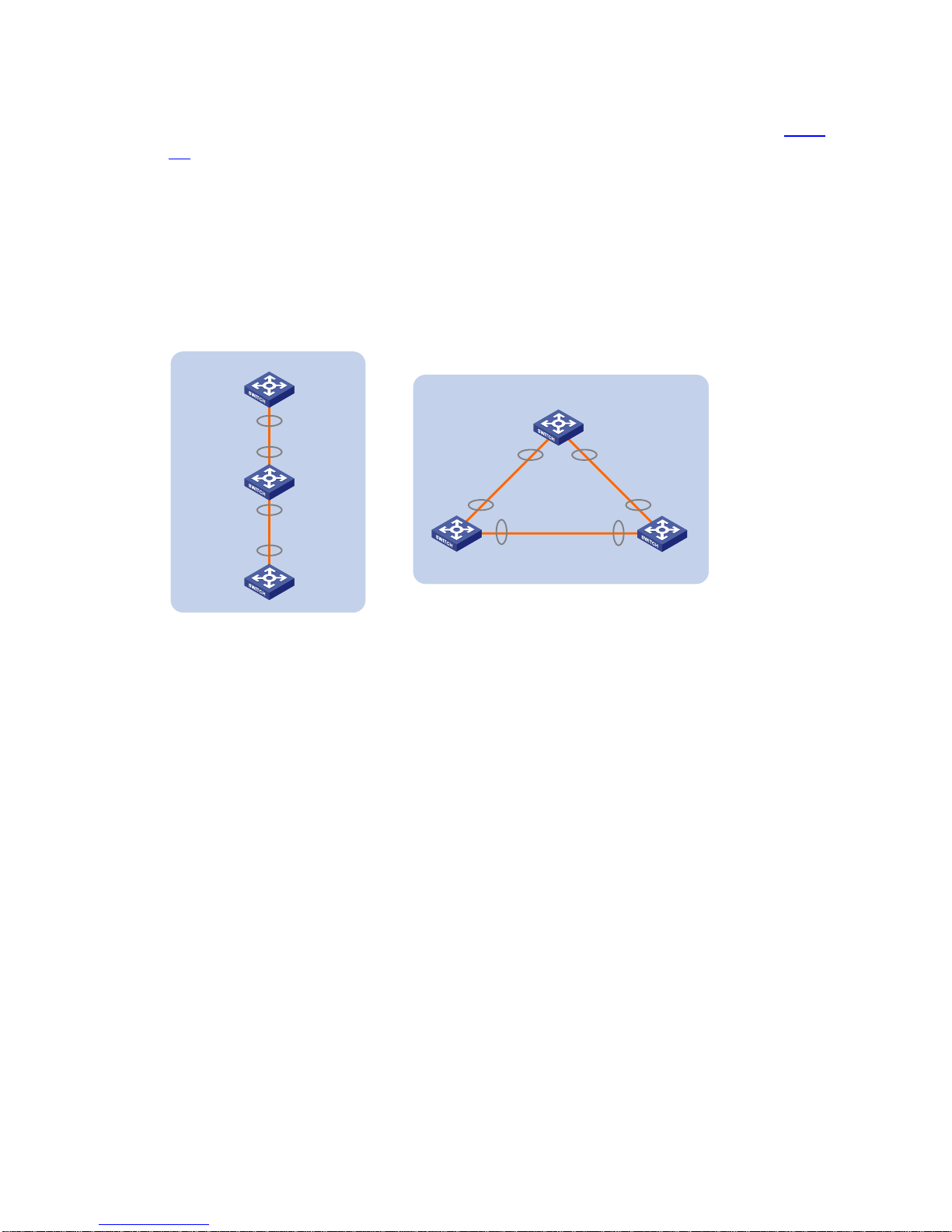
An IRF virtual device typically adopts daisy chain connection or ring connection, as shown in Figure
1-5.
z A daisy chain connection is mainly used in a network where member devices are distributedly
located.
z A ring connection is more reliable than the daisy chain connection. In a daisy chained IRF virtual
device, the failure of one link can cause the IRF virtual device to partition into two independent IRF
virtual devices; where the failure of a link in a ring connection result in a dai sy chain connection, not
affecting IRF services.
Figure 1-5 IRF connections
IRF virtual
device
Ring connection
Slave Slave
Master
IRF-Port1 IRF-Port2
IRF-Port1
IRF-Port2IRF-Port1
IRF-Port2
Daisy chain
connection
IRF
virtual
device
Master
Slave
Slave
IRF-Port2
IRF-Port2
IRF-Port1
IRF-Port1
Topology Collection
Each member exchanges hello packets with the directly conne cted neighbors to collect topolo gy of the
IRF virtual device. The hello packets carry topology information, including IRF port connection states,
member IDs, priorities, and bridge MAC addresses.
Each member records its known topology information locally. At the initiation of the collection, the
members record their own topology information. When an IRF port of a member becomes up, the
member sends its known topology information from this port periodically. Upon receiving the topology
information, the directly connected neighbor updates the local topology information.
The collection process lasts for a period of time. When all members have obtained the complete
topology information (known as topology convergence), the IRF virtual device enters the next stage:
role election.
Role Election
The process of defining the role (master or slave) of members is role election.
Role election is held when the topology changes, such as, forming an IRF virtual device, adding a new
member, leaving or failu re of the master, or IRF virtual device partition. The master is elected based on
Page 14

1-7
the rules below, in the order specified. If the first rule does not apply, a second rule is tried, and so on,
until the only winner is found.
z The current master, even if a new member has a higher priority. (When an IRF virtual device is
being formed, all member devices consider themselves as the mast er, so this principle is skip ped)
z A member with a higher priority.
z A member with the longest system up-time. (The system up-time information of each device is
delivered through IRF hello packets)
z A member with the lowest bridge MAC address.
Then, the IRF virtual device is formed and enters the next stage: IRF virtual device management and
maintenance.
z The precision of the system up-time is six minutes. For example, if two member devices with the
same priority values reboot one after another within six minutes, they have the same system
up-time and the last role election rule mentioned abov e is applied. In other word s, the one with the
lowest bridge MAC address wins.
z Merge: The process of connecting two existing IRF virtual devices with cables. When two IRF
virtual devices are merged into one, an election is held, and members of the loser side reboot and
join the winner side as slaves.
z Partition: For an IRF virtual device, IRF link failure or power-off of a member causes physical
disconnection between two devices. The process is called IRF virtual device partition.
IRF Virtual Device Management
After role election, an IRF virtual device is established: all member devices operate as one virtual
device on the network, and all resources on the member devices are processed by this virtual device
and managed by the master .
Member ID
An IRF virtual device uses member IDs to uniquely identify and manage its members. For a device that
does not support IRF, an interface is named GigabitEthernet 1/0/1, where the first number is always 1;
for a device that supports IRF, if its member ID is 2, the name of the interface is GigabitEthernet 2/0/1,
where the first number indicates the member ID of the device.
A member ID is ranges from 1 to 10 and defaults to 1. To ensure the uniqueness of member IDs, plan
and configure member IDs before member devices join the IRF virtual device.
When multiple devices form an IRF virtual device, a logical distributed device is formed. Each member
device acts as a card on the distributed device. The master acts as the active main board (AMB), the
slaves act as the standby main boards (SMBs), and each member device also acts as an interface
board.
As shown in
Figure 1-6, an IRF virtual device comprises four members, whi ch are numbered 1, 2, 3 and
4. When the IRF virtual device is established, it functions like a distributed device: slot s 1,2, 3 and 4 are
Page 15

1-8
inserted with cards, and each card has its own power supply unit (PSU), fan, CPU, console port and
Ethernet ports.
Figure 1-6 IRF virtual device
Interface name
For a device that operates independently (in other words, the device does not belong to any IRF virtual
device), its interface name is in the format of member ID/slot number/interface serial number, where:
z The default member ID is 1.
z When a device leaves an IRF virtual device, it retains its member ID.
z Subslot number is the number of the slot in which the interface card resides. On the S5820X series
or S5800 series, the subslot of the fixed port on the front panel is numbered 0; if the swit ch has only
one expansion slot, the subslot of this slot is numbered 1; if the switch has two expansion slots, the
subslots of the two expansion slots are numbered 1 and 2 from left to right.
z Interface serial number is dependent on the number of interfaces supported by the device. View
the silkscreen on the interface card for the number of supported interfaces.
For example, GigabitEthernet 1/0/1 is an interface on the independently operating device Sysname. T o
set the link type of GigabitEthernet 1/0/1 to trunk, perform the following steps:
<Sysname> system-view
[Sysname] interface gigabitethernet 1/0/1
[Sysname-GigabitEthernet1/0/1] port link-type trunk
For a member of an IRF virtual device, the interface name also adop ts the previously introduced format:
member ID/slot number/interface serial number, where
z The member ID identifies the IRF member on which the interface resides.
z Meaning and value of the subslot number and the interface serial number are the same as those
on an independently operating device.
For example, GigabitEthernet 1/0/1 is an interface on slave 3 (member ID is 3). To set the link type of
GigabitEthernet 1/0/1 to trunk, perform the following steps:
<Master> system-view
[Master] interface gigabitethernet 3/0/1
[Master-GigabitEthernet3/0/1] port link-type trunk
Page 16

1-9
File naming rules
You can use the name of a storage medium to access files on an independently operating device. For
the naming rules of a storage medium, see File Management Configuration in the Configuration
Fundamentals Configuration Guide.
To access the files of the master, use the name of the storage medium; to access files of a slave, use
the name in the following format: Member-ID#Storage-device-name.
For example:
1) To access the test folder in the root directory of the flash on the master, perform the following
steps:
<Master> mkdir test
...
%Created dir flash:/test.
<Master> dir
Directory of flash:/
0 -rw- 10105088 Apr 26 2000 13:44:57 test.app
1 -rw- 2445 Apr 26 2000 15:18:19 config.cfg
2 drw- - Jul 14 2008 15:20:35 test
30861 KB total (20961 KB free)
2) To create and access the test folder in the root directory of the flash on slave 3, perform the
following steps:
<Master> mkdir slot3#flash:/test
%Created dir slot3#flash:/test.
<Master> cd slot3#flash:/test
<Master> pwd
slot3#flash:/test
Or:
<Master> cd slot3#flash:/
<Master> mkdir test
%Created dir slot3#flash:/test.
3) To copy the test.app file on the master to the root directory of the flash on slave 3, perform the
following steps:
<Master> pwd
slot3#flash:
//The above information shows that the current working path is the root directory of the flash on slave 3.
<Master> cd flash:/
<Master> pwd
flash:
// The above operations show that the current working path is the root directory of the flash on the
master.
<Master> copy test.app slot3#flash:/
Copy flash:/test.app to slot3#flash:/test.app?[Y/N]:y
%Copy file flash:/test.app to slot3#flash:/test.app...Done.
Configuration file management
1) Configuration file synchronization
Page 17

1-10
IRF uses a strict configuration file synchronization mechanism to ensure that the members of an IRF
virtual device can work as a single device and that when the maste r fails, the other devices can operate
normally.
z When a slave starts up, it automatically searches for the master, synchronizes the master's
configuration file, and executes the configuration file. If all members start up simultaneously, the
slaves synchronize the master's initial configuration file and execute it.
z When the IRF virtual device operates normally, all your configurations are recorded into the current
configuration file of the master, and are synchronized to each member device. When you save the
current configuration file of the master as the startup configuration file by using the save command,
all slaves execute the same saving operation to make the startup configuration file of all members
consistent.
Through the real-time synchronization, all members keep the same configuration file. Even if the
master fails, all the other devices can execute various functions based on the same configuration file.
2) Configuration file application
The configuration file can be divided into two parts: global configuration and port configuration. When a
slave applies these two kinds of configurations of the master, it handles them as follows:
z Global configuration: All slaves execute the current global configuration on the master. In other
words, all members apply the same global configuration.
z Port configuration: When a slave applies the port configuration of the master, it cares about the
configuration related to its own port. For example, the slave with member ID 3 only cares a bout the
configuration related to the GigabitEthernet 3/0/x port on the master. If there is a configuration
related to its own port, it applies the configuration; if not, no matter what configuration has been
made to the port before the slave joins the IRF, the slave functions by using the default
configuration.
IRF topology maintenance
Direct neighbors of an IRF virtual device periodically exchange hello packets (the period is 200 ms).
Without receiving any hello packet from a direct neighbor for 100 periods, a member considers that the
hello packets timed out, and the expired device is isolated and the topology database is updated.
When an IRF port of a member is down, the member immediately broadcasts the information to all the
other members. If the IRF port of the master is down, an election is triggered.
IRF Multi-Active Detection (MAD) Mechanism
A link disconnection cau ses an IRF virtual device to divide into two or more IRF virtual devices with the
same global configuration, which may cause a network failure. Therefore, the multi-active detection
(MAD) mechanism is introduced to detect whether devices on the two sides of the detected link belong
to the same IRF virtual device and then judge whether the IRF virtual device is already p a rtitioned i nto
multiple IRF virtual devices. The MAD mechanism provides the following functions:
z Detection: Enabled for an IRF virtual device, the MAD mechanism detects the network for multiple
active IRF virtual devices with the same global configuration. This is done with the Link
Aggregation Control Protocol (LACP) or the Bidirectional Forwarding Detection (BFD) protocol.
z Collision handling: When an IRF virtual device is partitioned, if multiple active IRF virtual devices
are detected, the MAD mechanism keeps only the one with the lowest master ID to operate
normally (keeping the active state). The state of all the other IRF virtual devices are set to recovery
Page 18

1-11
(disabled) and all physical ports (usually the service ports) in them are shut down except for the
reserved ones to make sure that these IRF virtual devices cannot forward data traffic.
z Failure recovery: An IRF link failure triggers IRF virtual device partition and thus causes
multi-active collision. In this case, repair the failed IRF link to make the collided IRF virtual devices
merge into one and the failure is recovered. If the IRF virtual device in the recovery state fails
before the failure is recovered, repair both the failed IRF virtual device and the failed IRF link, and
then the collided IRF virtual devices can merge into one and the failure is recovered. If the IRF
virtual device in the active state fails before the failure is recovered, enable the IRF virtual device in
the recovery state at the CLI to make it take over the active IRF virtual device and protect the
services from being affected. Then, recover the MAD failure.
z When an IRF virtual device is portioned, the system disables all service ports on the member
devices from the loser side (equal to executing the shutdown command on these ports). However,
some ports are not disabled and they are called reserved ports. By default, only physical IRF port s
can be set to reserved ports. To set other ports (such as the port for telnetting) to reserved ports,
configure them at the CLI.
z For configuration information about LACP, see Ethernet Link Aggregation Configuration in the
Layer 2 - LAN Switching Configuration Guide; for configuration information about BFD, see BFD
Configuration in the High Availability Configuration Guide.
IRF Virtual Device Configuration Task List
Before configuring an IRF virtual device, define the roles and functions of all the members. Because
some configurations takes effect after device reboot, you are recommended to follow the procedure
shown in
Figure 1-7.
Figure 1-7 IRF configuration flow chart
You can connect physical IRF ports with SFP+ cables or fibers after activating IRF port configurations.
After the device detects that the IRF ports are conn ected no rmally, role election is started immediately,
and then the elected slaves automatically reboot.
When an IRF virtual device is formed, you can configure and manage it by logging in to any member
device. The operations you make take effect on the m aster , and are applied to all member devices. For
Page 19

1-12
easy fault location and device maintenance, the S5820X series or S5800 series provides slave view,
where you can execute the display, terminal, and debug commands.
Complete the following tasks to configure an IRF virtual device:
Task Remarks
Specifying a Domain ID for an IRF Virtual Device Optional
Setting a Member ID for a Device Optional
Configuring IRF Ports Required
Specifying a Priority for a Member Required
Specifying the Preservation Time of the Bridge MAC
Address
Optional
Enabling Auto Upgrade of Boot Files Optional
IRF Virtual Device
Configuration
Setting the Delay Time for the Link Layer to Report a
Link-Down Event
Optional
Connect the physical IRF ports of devices by using SFP+ cables or optical fibers (a ring connection is
recommended), and then power on the devices.
Configuring LACP MAD Optional
Configuring BFD MAD Optional
Excluding a Port from the Shut Down Action upon
Detection of Multi-Active Collision
Optional
Configuring MAD Detection
Manually Recovering an IRF Virtual Device Optional
Logging In to the Master Required
Logging In to an IRF Virtual
Device
Logging In to a Slave Optional
To avoid influence to your network caused by accidental partition of an IRF virtual device, you are
recommended to enable the MAD detection function after establishing the IRF virtual device.
IRF Virtual Device Configuration
Specifying a Domain ID for an IRF Virtual Device
Introduction to domain
To differentiate IRF virtual devices, each IRF virtual device is assigned a domain ID.
As shown in
Figure 1-8, Switch A and Switch B form IRF virtual device 1, and Switch C and Switch D
form IRF virtual device 2. If there is an LACP MAD detection link between IRF virtual device 1 and IRF
virtual device 2, they send MAD detection packets to each other through the detection link. In this case,
the system statuses and operations of both IRF virtual device 1 and IRF virtual device 2 are affected. To
solve this problem, specify different domain IDs for the two IRF virtual devices.
Page 20

1-13
Figure 1-8 Network diagram for multiple domains
Switch A Switch B
IRF virtual device 1
(domain 10)
IRF link
Core network
IRF virtual device 2
(domain 20)
IRF link
Switch C
Switch D
Access network
Assigning a domain ID to an IRF virtual device
If LACP MAD detection is applied for multiple IRF virtual devices and LACP MAD detection links exist
among the IRF virtual devices, assign different domain IDs for the IRF virtual devices. If there is no
LACP MAD detection link among IRF virtual devices, or BFD MAD detection is applied, you do not need
to assign domain IDs to them.
Follow these steps to assign a domain ID to an IRF virtual device:
To do… Use the command… Remarks
Enter system view
system-view
—
Assign a domain ID to an IRF
virtual device
irf domain
domain-id
Optional
By default, the domain ID of an
IRF virtual device is 0.
Page 21

1-14
z You must assign a domain ID for an IRF virtual device before enabling LACP MAD detection.
z Although devices with different domain IDs can form an IRF virtual device, you are recommended to
assign the same domain ID to the members of the same IRF virtual device; otherwise, the LACP
MAD detection function cannot function properly.
z To display the domain IDs and verify your configuration, execute the display irf command in any
view.
Setting a Member ID for a Device
The member ID of a device defaults to 1. During the establishment of an IRF virtual device, if the
member IDs of two devices are duplicate, you need to manually change the member IDs. Therefore,
you are recommended to plan and configure the member ID for each member before configuring an
IRF virtual device.
For a device that is already a member of an IRF virtual device, use the commands in
Table 1-3 to
change the member ID of the device. Your modification takes effect at the reboot of the device.
For a device that is not a member of an IRF virtual device, you are recommended to set it s me mber ID
as follows:
1) Plan the member ID in advance. View the member IDs of all member devices, and select an
unused ID for the new device.
2) Log in to the device, and change its member ID to the unused ID found out in step 1.
3) Save the current configuration. Power off the device, connect the device to the IRF virtual device
with SFP+ cables or fibers and power it on. Use the configuration introduced in this section to
enable IRF on the device and add it into the IRF virtual device.
Table 1-3 Set a member ID for a device
To do… Use the command… Remarks
Enter system view
system-view
—
Set a member ID for a device
irf member
member-id
renumber
new-id
Optional
The member ID of a device
defaults to 1
Page 22

1-15
z Member ID change takes effect at the reboot of a device.
z To view the current member ID of a device, use the display irf configuration command. The
member ID takes effect at the device reboot.
z Member IDs are not only used to identify members of an IRF virtual device, but also used to
identify the port configurations on different members. Therefore, member ID change may cause
device configuration changes or even losses, so change member ID with caution. For example,
three members (of same device model) with the member IDs of 1, 2 and 3 are connected to an IRF
port. Assume that each member has several ports: change the member I D of device 2 to 3, change
that of device 3 to 2, reboot both devices, and add them into the IRF virtual device again. Then
device 2 uses the original port configurations of device 3, and device 3 uses those of device 2.
Configuring IRF Ports
Configuring the correspondence between an IRF port and a physical IRF port
IRF can run on a device only when IRF ports are bound with physi cal IRF ports.
For how to bind IRF ports and physical IRF ports, see
Correspondence between an IRF port and a
physical IRF port
.
Follow these steps to configure IRF ports:
To do… Use the command… Remarks
Enter system view
system-view
—
Enter physical IRF port view
interface
interface-type
interface-number
—
Shut down the port
shutdown
Required
Return to system view
quit
—
Create an IRF port and enter IRF
port view
irf-port
member-id/port-number
Required
No IRF port is created on the
device by default.
If the IRF port is already created,
you can use this command to
enter IRF port view.
Bind a physical IRF port to the
IRF port
port group interface
interface-type
interface-number [
mode
{
enhanced
|
normal
} ]
Required
By default, no physical IRF port
is bound to the IRF port.
Return to system view
quit
—
Enter physical IRF port view
interface
interface-type
interface-number
—
Bring up the port
undo shutdown
Required
Return to system view
quit
—
Save the current configuration
save
Required
Page 23

1-16
To do… Use the command… Remarks
Activate configurations on all IRF
ports on the device
irf-port-configuration active
Optional
When you physically connect the
devices and bind physical IRF
port(s) to an IRF port whose link
state is
DIS
or
DOWN
, which you
can display with the
display irf
topology
command, this step is
required to establish an IRF
virtual device.
z To bind several physical IRF ports to an IRF port, or, in other words, to form an aggregate IRF port,
execute the port group interface command for multiple times Aggregate IRF ports expand
network bandwidth and provide link redundancy. You can bind at most four physical IRF ports to
one IRF port on the S5820X series or S5800 series.
z To bind multiple IRF physical ports to one IRF port, the physical location of these physical IRF
ports must meet the requirements of the conditions listed in
Correspondence between an IRF port
and a physical IRF port
.
z If you specify the mode keyword when you use the port group interface interface-type
interface-number [ mode { enhanced | normal } ] command to bind a physical IRF port to the IRF
port, the binding modes of ports on the two sides of the IRF link must be the same.
z When the IRF virtual device is established, if you need to plug out the interface card on which a
physical IRF port resides, first plug out the cables (SFP+ cables or fibers), or execute the
shutdown command in IRF physical port view to disable the port, and then plug out the interface
board.
Configuring IRF port load sharing mode
When you bind an IRF port to multiple physical IRF ports, an aggregate IRF port is formed. When data
is forwarded among members of the IRF virtual device, aggregate IRF ports can realize load sharing
and thus increase link utilization.
The S5820X series and S5800 series switches implement load sharing through the hash algorithm,
which can perform hash functions with different hash keys (that is, different load sharing modes). The
IP or MAC address carried by a packet, inbound port number, or a certain combination of these
parameters can be used as the hash key. You can flexibly share load on aggregate IRF ports by
switching the load sharing mode.
When you specify a load sharing mode, the switch extracts the corresponding field (IP addre ss or MAC
address) in a packet or the inbound port number based on the selected mode, and performs the hash
function on the address or port number and the number of physical IRF ports in an aggregate IRF port,
and then determines which physical IRF port sends out the packet. In this way, Load can be shared
among multiple physical IRF ports.
To configure IRF port load sharing mode, use either of the following two approaches.
z Configuring global IRF port load sharing mode
Page 24

1-17
Follow these steps to configure global IRF port load sharing mode:
To do… Use the command… Remarks
Enter system view
system-view
—
Configure global IRF port
load sharing mode
irf-port load-sharing mode
{
destination-ip
|
destination-mac
|
source-ip
|
source-mac
} *
Required
By default,
z The S5800-56C and
S5800-56C-PWR switches use the
inbound port number as the hash
key.
z Other models of the S5820X series
and S5800 series switches use the
combination of the source and
destination MAC addresses as the
hash key when processing Layer 2
packets, and use the combination
of the source and destination IP
addresses when processing Layer
3 packets.
This configuration is effective to all IRF
ports.
At present, when configuring IRF port load sharing mode in system view, you can specify:
z Any of the source IP address, destination IP address, source MAC address or destination MAC
address separately as the hash key.
z The combination of the source and the destination IP addresses as the hash key.
z The combination of the source and the destination MAC addresses as the hash key.
z Configuring load sharing mode for an IRF port
Follow these steps to configure load sharing mode for an IRF port:
To do… Use the command… Remarks
Enter system view
system-view
—
Enter IRF port view
irf-port member-id/port-number
—
Page 25

1-18
To do… Use the command… Remarks
Configure load sharing mode
for the current IRF port
irf-port load-sharing mode
{
destination-ip
|
destination-mac
|
source-ip
|
source-mac
} *
Required
By default,
z The S5800-56C and
S5800-56C-PWR switches use the
inbound port number as the hash
key
z Other models of the S5820X series
and S5800 series switches use the
combination of the source and
destination MAC addresses as the
hash key when processing Layer 2
packets, and use the combination
of the source and destination IP
addresses when processing Layer
3 packets.
If you have configured the load sharing
mode both globally and for an IRF port,
the configuration on the port takes
precedence. If the configuration on the
port is removed, the global
configuration is applied.
At present, when configuring IRF port load sharing mode in IRF port view, you can specify:
z Any of the source IP address, destination IP address, source MAC address or destination MAC
address separately as the hash key.
z The combination of the source and the destination IP addresses as the hash key.
z The combination of the source and the destination MAC addresses as the hash key.
Specifying a Priority for a Member
Each member of an IRF virtual device has a priority. A member with the greatest priority is preferably
elected as the master.
The priority of a device defaults to 1. You can modify the priority at the CLI. The greater the priority
value, the higher the priority. A member with a higher priority is more likely to be the master.
Follow these steps to specify a priority for a member:
To do… Use the command… Remarks
Enter system view
system-view
—
Specify a priority for a member of
an IRF virtual device
irf member
member-id
priority
priority
Optional
The priority of a member defaults
to 1.
Page 26

1-19
The priority setting takes effect right after your configuration without the need of rebooting the device.
Specifying the Preservation Time of the Bridge MAC Address
A device uses the bridge MAC address when it communicates with external networks as a bridge.
Some Layer 2 protocols (like LACP) use bridge MAC addresses to identify different devices. During
Layer 2 packet forwarding, if the destination MAC address of a packet is the bridge MAC address of a
device, the packet is sent to this device; otherwise, the packet is discarded. Therefore, a bridge device
on the network must have a unique bridge MAC address. If two devices on the network have t he same
bridge MAC addresses, bridge MAC address collision occurs and the communication fails.
An IRF virtual device communicates with external networks as a single device; therefore, it also has a
bridge MAC address, which is called the bridge MAC address of the IRF virtual device. T ypically, an IRF
virtual device uses the bridge MAC address of the master as its bridge MAC address.
Bridge MAC address collision causes communication failure, and bridge MAC address switching
causes traffic interruption. Therefore, you need to properly configure the preservati on time of the bridge
MAC address of the IRF virtual device:
z Preserve for six minutes: When the master leaves, the bridge MAC address does not change
within six minutes. If the master does not come back when the preserve time expired, the IRF
virtual device uses the bridge MAC address of the newly elected master as its bridge MAC address.
If the master leaves the IRF virtual device for a short time due to device reboot or link failure, this
configuration can reduce unnecessary switch of bridge MAC address and thus avoid traffic
interruption.
z Preserve permanently: No matter whether the master leaves the IRF virtual device or not, the
bridge MAC address of the IRF virtual device remains unchanged.
z Not preserved: As soon as the master leaves, the IRF virtual device uses the bridge MAC address
of the newly elected master as its bridge MAC address.
Follow these steps to specify the preservation time of t he bridge MAC ad dress of an IRF virtual device:
To do… Use the command… Remarks
Enter system view
system-view
—
Configure the bridge MAC address of
the IRF virtual device to be preserved
permanently when the master leaves
irf mac-address persistent always
Specify the preservation time of the
bridge MAC address of the IRF virtual
device as 6 minutes when the master
leaves
irf mac-address persistent timer
Configure that the bridge MAC
address of the IRF virtual device
changes as soon as the master
leaves
undo irf mac-address persistent
Optional
By default, the bridge
MAC address of an IRF
virtual device is preserved
for 6 minutes when the
master leaves.
Page 27

1-20
Bridge MAC address change may cause a temporary traffic interruption.
Enabling Auto Upgrade of Boot Files
If auto upgrade of boot files is disabled, when the boot files of slaves and the boot file of the master are
in different versions, the new member or the member with a low priority will not boot normally. Y ou need
to manually update the device version and add the device into the IRF virtual device again.
If auto upgrade of boot files is enabled, as soon as a device is added into an IRF virtual device, the IRF
virtual device compares its software version with that of the master. If the versions are not consistent,
the device automatically downloads the boot file from the master, reboots with the new boot file, and
joins the IRF virtual device again. If the downloaded boot file and the local file have duplicate file names,
the local file is overwritten.
Follow these steps to enable auto upgrade of boot files for an IRF virtual device:
To do… Use the command… Remarks
Enter system view
system-view
—
Enable auto upgrade of boot files
for an IRF virtual device
irf auto-update enable
Optional
Enabled by default
z Although an IRF virtual device supports the auto upgrade of boot files, you are recommended to
ensure that a new device and the master have the same software version before adding the into
the IRF virtual device, thus to shorten the time for IRF virtual device establishment and reduce the
influences caused by IRF virtual device establishment to the network,
z After automatically loading the master’s boot file, a slave configures the file as the boot file to be
used at the next boot and reboots automatically.
z To make the auto upgrade succeed, ensure that there is enough space on the storage media of
slaves because system boot file occupies large memory space.
Setting the Delay Time for the Link Layer to Report a Link-Down Event
After you set the delay time for the link layer to report a link-down event:
z If the IRF link state changes from up to down, the port does not immediately report the link state
changes to the system. After the configured time interval, if the IRF link state is still down, the port
reports the link state changes to the system, and then the system handles the problem
accordingly.
z If the link state changes from down to up, the link layer immediately reports the event to the
system.
Page 28

1-21
Use this function to avoid unnecessary IRF virtual device partition and merge caused by frequent link
state changes of a port in a short time.
Follow these steps to set the delay time for the link layer to report a link-down event of an IRF virtual
device:
To do… Use the command… Remarks
Enter system view
system-view
—
Set the delay time for the link
layer to report a link-down event
of an IRF virtual device
irf link-delay
interval
Optional
The function is disabled by
default.
Do not set the time interval to a very long time; otherwise, the IRF virtual device cannot be aware of the
topology changes in time and thus the service will be recovered slowly.
Configuring MAD Detection
The S5820X and S5800 series switches support two MAD approaches: BFD MAD detection and LACP
MAD detection.
z BFD MAD detection requires either direct connection or intermediate devices.
z LACP MAD detection requires intermediate devices, which must be capable of identifying and
processing LACPDU protocol packets that carry Active ID values.
The two approaches operate independently and do not interfere with one another; therefore, you can
configure two MAD detection approaches for one IRF virtual device.
Configuring LACP MAD
LACP MAD detection mechanism
LACP MAD is implemented by sending extended LACP dat a units (LACPDUs) with a type length value
(TL V) that conveys the a ctive ID of an IRF virtual devic e. The active ID is id entical to the member ID of
the master and is thus unique to the IRF virtual device.
When LACP MAD detection is enabled, the members exchange their active IDs by sending extended
LACPDUs.
z When the IRF virtual device operates normally, the active IDs in the extended LACPDUs sent by
all members are the same, indicating that there is no multi-active collision.
z When the IRF virtual device partitions, the active IDs in the extended LACPDUs sent by the
members in different IRF virtual devices are different, indicating that there are multi-active
collisions.
Networking requirements
LACP MAD requires intermediate devices that are capable of identifying and processing extended
LACPDUs to carry the Active ID field. For more information, refer to the LACP protocol section in
Ethernet Link Aggregation Configuration of the Layer 2 - LAN Switching Configuration Guide. The
Page 29

1-22
commonly used networking diagram is as shown in Figure 1-9: the member devices exchange
LACPDUs through Device.
Figure 1-9 Network diagram for LACP MAD detection
Device
Master
Slave
IRF virtual
device
Internet
Terminal
network
IRF link
Path where data traffic is transmitted
Path where LACP MAD packets are transmitted
Dynamic aggregation group on
Device, used for LACP MAD and
data traffic forwarding.
Dynamic aggregation group on
the IRF virtual device, used for
LACP MAD and data traffic
forwarding.
Configuring LACP MAD detection
Configure LACP MAD detection in the following order:
z Create an aggregate interface (also required on the intermediate device);
z Configure the aggregation group to work in dynamic aggregation mode; (also required on the
intermediate device)
z Enable LACP MAD detection on the dynamic aggregate interface; (also required on the
intermediate device)
z Add member ports to the aggregation group.(also required on the intermediate device)
Follow these steps to configure LACP MAD detection:
To do… Use the command… Remarks
Enter system view
system-view
—
Enter Layer 2 aggregate interface
view
interface bridge-aggregation
interface-number
—
Configure the aggregation group
to work in dynamic aggregation
mode
link-aggregation mode dynamic
Required
By default, the aggregation
group works in static aggregation
mode.
Page 30

1-23
To do… Use the command… Remarks
Enable LACP MAD detection
mad enable
Required
Disabled by default.
Even though this command can
be configured on both static and
dynamic aggregate interfaces, it
takes effect only on dynamic
aggregate interfaces. This is
because this detection approach
depends on LACP.
Return to system view
quit
—
Enter Ethernet interface view
interface
interface-type
interface-number
—
Assign the current Ethernet
interface to the specified
aggregation group
port link-aggregation group
number Required
Configuring BFD MAD
BFD MAD detection mechanism
BFD MAD is implemented with the BFD protocol. In this approach, to configure BFD MAD detection,
configure a MAD IP address on a BFD-enabled Layer 3 interface for each member device. This MAD
address identifies the member during BFD MAD detection. The MAD IP addresses assigned to the
member devices must belong to the same network segment.
z When the IRF virtual device operates normally, only the MAD IP address of the master is effective
and the BFD session is down.
z When the IRF virtual device partitions, the MAD IP addresses of the masters in different IRF virtual
devices become effective to activate the BFD sessions to detect for multi-active IRF virtual device
collision.
Network requirements
BFD MAD detection can be achieved with or without intermediate devices. The commonly used
networking diagram is as shown in
Figure 1-10: there must be a BFD MAD detection link among all
members, and the interfaces connected by this link must belong to the same VL AN. In VLAN interface
view, assign different IP addresses on the same network segment for different member devices.
A Layer 3 interface used for BFD MAD must be dedicated. Do not configure any other services on a
Layer 3 interface with BFD MAD enabled; otherwise, both the configured services and the BFD MAD
detection function may be affected.
Page 31

1-24
Figure 1-10 Network diagram for BFD MAD detection
Device
Master
Slave
IRF
Internet
Terminal
network
IRF link
Aggregation group on
Device, used for data
traffic forwarding.
BFD MAD link
Vlan2
192.168.1.2/24
Vlan2
192.168.1.3/24
Configuring BFD MAD detection
Configure BFD MAD detection in the following order:
z Create a VLAN dedicated for BFD MAD detection; (also required on the intermediate device, if
any)
z Select the physical IRF ports to be used for BFD MAD detection (at least one on each member
device) and add them into the detection-dedicated VLAN; (also required on the intermediate
device, if any)
z Create VLAN interfaces for the detection-dedicated VLAN, enable BFD MAD detection on these
interfaces, and then assign MAD IP addresses for them.
Follow these steps to configure BFD MAD:
To do… Use the command… Remarks
Enter system view
system-view
—
Create a new VLAN dedicated for
the BFD MAD detection
vlan
vlan-id
Required
The default VLAN on the device
is VLAN 1.
Return to system view
quit
—
Enter Ethernet interface view
interface
interface-type
interface-number
—
Page 32

1-25
To do… Use the command… Remarks
Access port
port access vlan
vlan-id
Trunk port
port trunk permit vlan
vlan-id
Assign the port
to the VLAN
dedicated for
the BFD MAD
detection
Hybrid port
port hybrid vlan
vlan-id
Required
You can select one approach
according to the port type.
BFD MAD detection has no
requirement on the link type of
the detection port, and you do
not need to modify the current
link type.
By default, the port is an access
port.
Return to system view
quit
—
Enter VLAN interface view
interface vlan-interface
interface-number
—
Enable BFD MAD
mad bfd enable
Required
Disabled by default.
Configure a MAD IP address for
the VLAN interface on the
specified member
mad ip address
ip-address { mask |
mask-length }
chassis
chassis-number
Required
By default, no MAD IP address is
configured for any interface.
z Add all ports (including ports on both the IRF member and the intermediate device) on the BFD
MAD detection link into the VLAN that corresponds to the VLAN interface used for the detection.
z A VLAN interface enabled with BFD MAD detection and the interfaces of this VLAN do n ot support
any Layer 2 and Layer 3 protocol applications, including ARP and LACP.
z You cannot enable BFD MAD detection on VLAN-interface 1.
z BFD MAD detection links are dedicated, and you are not allowed to configure other services on
BFD MAD detection link.
z Only the MAD IP address can be configured for a VLAN interface enabled with BFD MAC detection,
and other type of IP addresses are not allowed to be configured for it.
z If the BFD MAD detection link between two members is set up through an intermediate device,
disable the STP function on the intermediate device to ensure the normal function of BFD MAD
detection.
z If an IRF virtual device enabled with BFD MAD detection partitions, the partitioned IRF virtual
devices may still keep the forwarding entries destined to the original master, and thus routing
collision information is generated. The routing collision information does not affect data forwarding
and stops being generated when the entries are aged out.
Excluding a Port from the Shut Down Action upon Detection of Multi-Active Collision
By default, all service ports of an IRF virtual device except the IRF ports are shut down when the IRF
virtual device transits to recovery state upon detection of a multi-active collision. If a port must be kept
in the up state for special purposes such as telnet connection, excl ude it from the shut down action.
Page 33

1-26
Follow these steps to configure a port not to shut down when the IRF virtual device transits to recovery
state:
To do… Use the command… Remarks
Enter system view
system-view
—
Specify the reserved ports, which
are ports that are not disabled
when the device is in the recovery
state
mad exclude interface
interface-type
interface-number
Optional
By default, no reserved port is
specified. In other words, all
physical ports are automatically
disabled when the device is in
the recovery state.
z Physical IRF ports and console ports are not shut down when the IRF virtual device transits to
recovery state, and do not need to be configured as reserved ports.
z If a certain VLAN interface is required to go on receiving and sending packets (for example, the
VLAN interface is used for remote login) after the IRF virtual device transits to recovery state,
configure this VLAN interface and its corresponding Layer 2 Ethernet interface not to shut down
when the IRF virtual device transits to recovery state. However, if the VLAN interface is up in the
IRF virtual device in active state, IP collision occurs in your network.
Manually Recovering an IRF Virtual Device
An IRF link failure causes an IRF virtual device to divide into two IRF virtual devices and thus
multi-active collision occurs. When the system detects the collision, it holds a role election between the
two collided IRF virtual devices. The IRF virtual device whose master’s member ID is smaller prevails
and operates normally. The state of the other IRF virtual device transits to the recovery state and
cannot forward data packets temporally. In this case, recover the IRF virtual device by repairing the IRF
link first. (The device tries to automatically repair the failed IRF links. If the reparation fails, manually
repair the failed links.)
When the link is recovered, the IRF virtual device in the recovery state reboots and the two IRF virtual
devices merge into one. Service ports that were shut down and belonged to the IRF virtual device in the
recovery state restore their original physical state, as shown in
Figure 1-11.
Page 34

1-27
Figure 1-11 Auto-recovery of the IRF virtual device when the IRF link is repaired
If the IRF virtual device in the active state fails due to exceptions (a member fails or link failure occurs,
for example) before the IRF link is recovered, as shown in
Figure 1-12, enable IRF virtual device 2 (in
the recovery state) at the CLI by executing the mad restore command. Then, the state of IRF virtual
device 2 changes from recovery to active without the need of rebooting and takes over IRF virtual
device 1. Repair the IRF links. Two IRF virtual devices merge when the IRF link failure is recovered,
and the merged IRF virtual device recovers after the role election.
Figure 1-12 ecover the IRF virtual device in the recovery state at the CLI
Follow these steps to manually recover an IRF virtual device in recovery state:
To do… Use the command… Remarks
Enter system view
system-view
—
Recover an IRF virtual device in
recovery state
mad restore
Required
Page 35

1-28
If you change the state of an IRF virtual device from recovery to active and recover the failed IRF virtual
device whose original state was active, an election is held, and then members of the loser side reboot
and join the winner side as slaves.
Logging In to an IRF Virtual Device
Logging In to the Master
To access an IRF virtual device, perform either of the following two ways:
z Local login: Log in through the AUX or console port of a member device.
z Remote login: Configure an IP address for a VLAN interface of a member device and make sure
that the route is reachable, and then you can access the IRF virtual device remotely through Telnet,
Web, or SNMP.
When you log in to the IRF virtual device, actually you log in to the master. The master is the
configuration and control center of an IRF virtual device. After you configure the IRF virtual device on
the master, the IRF virtual device synchronizes the configurations to the slaves.
Logging In to a Slave
When you log in to an IRF virtual device, actually you log in to the master. To log in to a slave, redirect
to the slave. When you are redirected to a slave, the user access terminal displays the console of the
slave device instead of that of the master. The system enters user view of the slave and the command
prompt is changed to <Sysname-member ID>, for example, <Sysname-2>. What you have input on the
access terminal is redirected to the specified slave for processing. At present, only the following
commands are allowed to be executed on a slave:
z display
z quit
z return
z system-view
z debugging
z terminal debugging
z terminal trapping
z terminal logging
To return to the master console, press Ctrl+K or use the quit or return command. At this time, the
master console is reactivated, and therefore system information and logs can be output.
Follow these steps below to log in to the specified slave:
To do… Use the command… Remarks
Enter system view
system-view
—
Page 36

1-29
To do… Use the command… Remarks
Log in to the specified slave
irf switch-to
member-id
Required
By default, you actually log in to the
master when you log in to an IRF
virtual device.
Concurrent user login to an IRF virtual device occupies large memory spa ce. Therefore, a n IRF virtual
device allows at most 15 concurrent virtual type terminal (VTY) users. The maximum number of
permitted concurrent console login users is the same as the number of members of the IRF virtual
device.
Displaying and Maintaining an IRF Virtual Device
To do… Use the command… Remarks
Display information about the IRF
virtual device
display irf
Available in any view
Display topology information about
the IRF virtual device
display irf topology
Available in any view
Display the pre-configurations of all
members of the IRF virtual device
(The pre-configuration takes effect
at the reboot of the members.)
display irf configuration
Available in any view
Display the master/slave switchover
states of members of the IRF virtual
device
display switchover state
[ member-id ]
Available in any view
Display configuration information
about MAD detection
display mad [ verbose ]
Available in any view
Display the global IRF port load
sharing mode, or the load sharing
mode on an aggregate IRF port
display irf-port load-sharing mode
[
irf-port
[ member-id/port-number ] ]
Available in any view
IRF Virtual Device Configuration Examples
Configuration Example of Using the LACP MAD Detection
Network requirements
As shown in Figure 1-13, Device A and Device B are members of an IRF virtual device, which adopts
LACP MAD detection.
Page 37

1-30
Figure 1-13 Network diagram for an IRF virtual device that uses LACP MAD detection
Configuration procedure
1) Set member IDs
# Keep the default member ID of Device A unchanged.
# Set the member ID of Device B to 2.
<Sysname> system-view
[Sysname] irf member 1 renumber 2
Warning: Renumbering the switch number may result in configuration change or loss. Continue?
[Y/N]:y
[Sysname]
2) Power off the two devices and connect IRF links and LACP MAD detection links according to
Figure 1-13. Then power on the two devices.
# Create IRF port 2 on Device A, and bind it to physical IRF port Ten-GigabitEthernet 1/0/25. Then save
your configuration.
<Sysname> system-view
[Sysname] interface ten-gigabitethernet 1/0/25
[Sysname-Ten-GigabitEthernet1/0/25] shutdown
[Sysname] irf-port 1/2
[Sysname-irf-port 1/2] port group interface ten-gigabitethernet 1/0/25
[Sysname-irf-port 1/2] quit
[Sysname] interface ten-gigabitethernet 1/0/25
[Sysname-Ten-GigabitEthernet1/0/25] undo shutdown
[Sysname-Ten-GigabitEthernet1/0/25] save
# Create IRF port 1 on Device B, and bind it to physical IRF port Ten-GigabitEthernet 1/0/26. Then save
your configuration.
<Sysname> system-view
[Sysname] interface ten-gigabitethernet 2/0/26
[Sysname -Ten-GigabitEthernet2/0/26] shutdown
[Sysname] irf-port 2/1
[Sysname-irf-port 2/1] port group interface ten-gigabitethernet 1/0/25
[Sysname-irf-port 2/1] quit
[Sysname] interface ten-gigabitethernet 2/0/26
[Sysname-Ten-GigabitEthernet2/0/26] undo shutdown
[Sysname-Ten-GigabitEthernet2/0/26] save
# Activate IRF port configuration on Device A.
[Sysname-Ten-GigabitEthernet1/0/25] quit
[Sysname] irf-port-configuration active
# Activate IRF port configuration on Device B.
Page 38

1-31
[Sysname-Ten-GigabitEthernet2/0/26] quit
[Sysname] irf-port-configuration active
3) Two devices reboot automatically. Then, an IRF virtual device is established.
4) Configure LACP MAD detection
# Create a dynamic aggregation interface and enable LACP MAD detection.
<Sysname> system-view
[Sysname] interface bridge-aggregation 2
[Sysname-Bridge-Aggregation2] link-aggregation mode dynamic
[Sysname-Bridge-Aggregation2] mad enable
[Sysname-Bridge-Aggregation2] quit
# Add ports GigabitEthernet 1/0/1 and GigabitEthernet 2/0/1 to the aggregation interface and they are
dedicated to the LACP MAD detection for Device A and Device B.
[Sysname] interface gigabitethernet 1/0/1
[Sysname-GigabitEthernet1/0/1] port link-aggregation group 2
[Sysname-GigabitEthernet1/0/1] quit
[Sysname] interface gigabitethernet 2/0/1
[Sysname-GigabitEthernet2/0/1] port link-aggregation group 2
5) Configure Device C as the intermediate device
Acting as the intermediate device, Device C needs to support LACP to forward and process LACP
protocol packets, and help Device A and Device B implement MAD detection. An LACP-supported
switch is used here to save the cost.
# Create a dynamic aggregation interface.
<Sysname> system-view
[Sysname] interface bridge-aggregation 2
[Sysname-Bridge-Aggregation2] link-aggregation mode dynamic
[Sysname-Bridge-Aggregation2] quit
# Add ports GigabitEthernet 1/0/1 and GigabitEthernet 1/0/2 to the aggregation interface and they are
used for the LACP MAD detection.
[Sysname] interface gigabitethernet 1/0/1
[Sysname-GigabitEthernet1/0/1] port link-aggregation group 2
[Sysname-GigabitEthernet1/0/1] quit
[Sysname] interface gigabitethernet 1/0/2
[Sysname-GigabitEthernet1/0/2] port link-aggregation group 2
Configuration Example of Using the BFD MAD Detection
Network requirements
As shown in Figure 1-14, Device A and Device B are members of an IRF virtual device, which adopts
BFD MAD detection.
Figure 1-14 Network diagram for an IRF virtual device that uses BFD MAD detection
Configuration procedure
1) Set member IDs
Page 39

1-32
# Keep the default member ID of Device A unchanged.
# Set the member ID of Device B to 2.
<Sysname> system-view
[Sysname] irf member 1 renumber 2
Warning: Renumbering the switch number may result in configuration change or loss. Continue?
[Y/N]:y
[Sysname]
2) Power off the two devices and connect IRF links and BFD MAD detection links according to Figure
1-14. Then power on the two devices.
# Create IRF port 2 on Device A, and bind it to physical IRF port Ten-GigabitEthernet 1/0/25. Then save
the configuration.
<Sysname> system-view
[Sysname] interface ten-gigabitethernet 1/0/25
[Sysname-Ten-GigabitEthernet1/0/25] shutdown
[Sysname] irf-port 1/2
[Sysname-irf-port 1/2] port group interface ten-gigabitethernet 1/0/25
[Sysname-irf-port 1/2] quit
[Sysname] interface ten-gigabitethernet 1/0/25
[Sysname-Ten-GigabitEthernet1/0/25] undo shutdown
[Sysname-Ten-GigabitEthernet1/0/25] save
# Create IRF port 1 on Device B, and bind it to physical IRF port Ten-GigabitEthernet 1/0/26. Then save
the configuration.
<Sysname> system-view
[Sysname] interface ten-gigabitethernet 2/0/26
[Sysname -Ten-GigabitEthernet2/0/26] shutdown
[Sysname] irf-port 2/1
[Sysname-irf-port 2/1] port group interface ten-gigabitethernet 1/0/25
[Sysname-irf-port 2/1] quit
[Sysname] interface ten-gigabitethernet 2/0/26
[Sysname-Ten-GigabitEthernet2/0/26] undo shutdown
[Sysname-Ten-GigabitEthernet2/0/26] save
# Activate IRF port configuration on Device A.
[Sysname-Ten-GigabitEthernet1/0/25] quit
[Sysname] irf-port-configuration active
# Activate IRF port configuration on Device B.
[Sysname-Ten-GigabitEthernet2/0/26] quit
[Sysname] irf-port-configuration active
3) Two devices reboot automatically. Then, an IRF virtual device is established.
4) Configure BFD MAD detection
# Create VLAN 3, and add port GigabitEthernet 1/0/1 on Device A (with the member ID of 1) and port
GigabitEthernet 2/0/1 on Device B (with the member ID of 2) to VLAN 3.
<DeviceA> system-view
[DeviceA] vlan 3
[DeviceA-vlan3] port gigabitethernet 1/0/1 gigabitethernet 2/0/1
[DeviceA-vlan3] quit
# Create VLAN-interface 3 and configure the MAD IP address for the interface.
[Sysname] interface vlan-interface 3
[Sysname-Vlan-interface3] mad bfd enable
Page 40

1-33
[Sysname-Vlan-interface3] mad ip address 192.168.2.1 24 member 1
[Sysname-Vlan-interface3] mad ip address 192.168.2.2 24 member 2
[Sysname-Vlan-interface3] quit
Page 41

2-1
2 Index
A
Advantages
1-1
Application and Advant ages
1-2
C
Configuration Example of Using the BFD
MAD Detection
1-31
Configuration Example of Using the LACP
MAD Detection
1-29
Configuring BFD MAD
1-23
Configuring IRF Ports
1-15
Configuring LACP MAD
1-21
E
Enabling Auto Upgrade of Boot Files
1-20
Excluding a Port from the Shut Down Action
upon Detection of Multi-Active Collision
1-25
I
Introduction
1-1
IRF Multi-Active Detection (MAD) Mechanism
1-10
IRF Virtual Device Management
1-7
L
Logging In to a Slave
1-28
Logging In to the Master
1-28
M
Manually Recovering an IRF Virtual Device
1-26
P
Physical Connections
1-4
R
Role Election
1-6
S
Setting a Member ID for a Device
1-14
Setting the Delay Time for the Link Layer to
Report a Link-Down Event
1-20
Specifying a Domain ID for an IRF Virtual
Device
1-12
Specifying a Priority for a Member
1-18
Specifying the Preservation Time of the
Bridge MAC Addre ss
1-19
T
Topology Collection
1-6
 Loading...