

Page 1

H3C S5810 Series Ethernet Switches
Quick Start
Hangzhou H3C Technologies Co., Ltd.
http://www.h3c.com
Manual Version: 6PW102-20101105
Page 2

Copyright © 2009-2010, Hangzhou H3C Technologies Co., Ltd. and its licensors
All Rights Reserved
No part of this manual may be reproduced or transmitted in any form or by any means without prior
written consent of Hangzhou H3C Technologies Co., Ltd.
Trademarks
H3C, , Aolynk, , H3Care,
SecPro, SecPoint, SecEngine, SecPath, Comware, Secware, Storware, NQA, VVG, V
XGbus, N-Bus, TiGem, InnoVision and HUASAN are trademarks of Hangzhou H3C Technologies Co.,
Ltd.
All other trademarks that may be mentioned in this manual are the property of their respective owners.
Notice
The information in this document is subject to change without notice. Every effort has been made in the
preparation of this document to ensure accuracy of the contents, but all statements, information, and
recommendations in this document do not constitute the warranty of any kind, express or implied.
Technical Support
customer_service@h3c.com
http://www.h3c.com
, TOP G, , IRF, NetPilot, Neocean, NeoVTL,
2
G, VnG, PSPT,
Page 3

About This Manual
Organization
H3C S5810 Series Ethernet Switches Quick Start is organized as follows:
Chapter Contents
1 Product Overview
2 Installation Preparations
3 Installing a Switch
4 Initial Power-On
5 Maintenance and
Troubleshooting
Appendix
Conventions
The manual uses the following conventions:
Briefly introduces the appearance, system description, as well as
the features and applications of the H3C S5810 series switches.
Describes the requirements on installation site, the safety
recommendations before and during installation, and the required
tools.
Covers the procedures for installing the H3C S5810 series,
ground wire connection, power module installation, interface
module installation, and so on.
Helps you get familiar with the basic knowledge of how to boot and
configure the H3C S5810 series, including device startup,
power-on, and initialization of system files, and so on.
Introduces how to maintain software and hardware of the H3C
S5810 series.
Appendix A: Lightning protection of the H3C S5810 series switch.
Appendix B: Provides Compliance and safety manual.
GUI conventions
Convention Description
< > Button names are inside angle brackets. For example, click <OK>.
[ ]
/
Window names, menu items, data table and field names are inside
square brackets. For example, pop up the [New User] window.
Multi-level menus are separated by forward slashes. For example,
[File/Create/Folder].
Symbols
Convention Description
Means reader be extremely careful. Improper operation may cause
bodily injury.
Means reader be careful. Improper operation may cause data loss or
damage to equipment.
Means a complementary description.
Page 4

Related Documentation
Manual Description
H3C S5810 Series Ethernet Switches
Installation Manual
H3C S5810 Series Ethernet Switches Operation
Manual
H3C S5810 Series Ethernet Switches Command
Manual
Introduces the appearance, installation,
power-on and startup, troubleshooting and
maintenance of the H3C S5810 series Ethernet
switches.
It includes Product Overview, Access Volume, IP
Service Volume, IP Routing Volume, IP Multicast
Volume, QoS Volume, Security Volume, System
Volume and Acronyms.
It includes Feature List and Command Index,
Access Volume, IP Services Volume, IP Routing
Volume, IP Multicast Volume, QoS Volume,
Security Volume and System Volume
commands.
H3C PSR300-12A & PSR300-12D1 Power
Modules User Manual
H3C LSWM1FAN & LSWM1BFAN Installation
Manual
Obtaining Documentation
You can access the most up-to-date H3C product documentation on the World Wide Web at this URL:
http://www.h3c.com.
The following are the columns from which you can obtain different categories of product docume ntation:
[Products & Solutions]: Provides information about products and technologies, as well as solutions.
[Technical Support & Document > Technical Documents]: Provides several categories of product
documentation, such as installation, operation, and maintenance.
[Technical Support & Document > Product Support > Software]: Provides the documentation released
with the software version.
Documentation Feedback
Introduces the features, specifications,
installation and removal of the PSR300-12A and
PSR300-12D1 power modules.
Introduces the features, specifications,
installation and removal of the LSWM1FAN and
LSWM1BFAN fan modules.
You can e-mail your comments about product documentation to info@h3c.com.
We appreciate your comments.
Environmental Protection
This product has been designed to comply with the requirements on environmental protection. For the
proper storage, use and disposal of this product, national laws and regulations must be ob served.
Page 5

Table of Contents
1 Product Overview······································································································································1-1
Overview ·················································································································································1-1
S5810-50S ··············································································································································1-2
Front Panel ······································································································································1-2
Rear Panel·······································································································································1-4
S5810-50S-DC········································································································································1-4
Front Panel ······································································································································1-4
Rear Panel·······································································································································1-5
Ports························································································································································1-5
Console Port····································································································································1-5
Management Ethernet Port ·············································································································1-6
USB Interface ··································································································································1-6
10/100/1000Base-T Ethernet Port···································································································1-6
100/1000Base-X SFP Interface·······································································································1-6
SFP+ Interface·································································································································1-8
LEDs························································································································································1-9
System LED···································································································································1-10
Power Module Status LEDs ··········································································································1-10
Seven-Segment LED·····················································································································1-10
Port Mode LED ······························································································································1-11
10/100/1000Base-T Auto-Sensing Ethernet Port Status LED·······················································1-11
100/1000Base-X SFP Interface Status LED ·················································································1-12
SFP+ Interface Status LED ···········································································································1-13
Management Ethernet Port Status LED ························································································1-13
Pluggable Power Modules ····················································································································1-13
AC Power Module··························································································································1-14
DC Power Module ·························································································································1-14
Ventilation System ································································································································1-14
2 Installation Preparations···························································································································2-1
Safety Precautions ··································································································································2-1
Installation Site········································································································································2-1
Temperature/Humidity·····················································································································2-1
Cleanness········································································································································2-2
Electromagnetic Susceptibility·········································································································2-2
Laser Safety ····································································································································2-2
Installation Tools ·····································································································································2-3
3 Installing a Switch ·····································································································································3-1
Installing the Switch into a 19-Inch Rack Using Mounting Brackets·······················································3-1
Introduction to Mounting Brackets···································································································3-1
Attaching the Mounting Brackets to a Switch··················································································3-1
Mounting the Switch to a Rack········································································································3-2
Mounting the Switch on a Workbench ····································································································3-3
Connecting the Ground Wire ··················································································································3-4
i
Page 6

Installing a Power Module·······················································································································3-6
Verifying the Installation··························································································································3-6
4 Initial Power-On ·········································································································································4-1
Setting Up the Configuration Environment······························································································4-1
Connecting the Console Cable ···············································································································4-1
Console Cable ·································································································································4-1
Connection Procedure·····················································································································4-1
Setting Terminal Parameters ··················································································································4-2
Booting the Switch ··································································································································4-5
Checking before Power-On ·············································································································4-5
Powering On the Switch ··················································································································4-5
Changing the Boot Mode·················································································································4-8
5 Maintenance and Troubleshooting··········································································································5-1
Software Loading Failure ························································································································5-1
Password Loss········································································································································5-1
User Password Loss························································································································5-1
Boot ROM Password Loss ··············································································································5-1
Power Supply Failure······························································································································5-2
Fan Tray Failure······································································································································5-2
Configuration Terminal Failure················································································································5-2
ii
Page 7

1 Product Overview
Overview
The H3C S5810 Series Ethernet Switches (hereinafter referred to as the S5810 series) are
high-performance gigabit Ethernet switches developed by Hangzhou H3C Technologies Co., Ltd.
(hereinafter referred to as H3C). The S5810 series adopt advanced hardware structure design and
provide excellent inbound/outbound cache capability. The dual power module slot design enhances the
device availability, making the device applicable to the Top of Rack application at data centers.
The H3C S5810 series includes the following two models, and has the system specifications as shown
Table 1-1.
in
z S5810-50S
z S5810-50S-DC
Table 1-1 The S5810 series system specifications
Item S5810-50S/S5810-50S-DC
Dimensions (H × W × D) 43.6 × 440 × 420 mm (1.72 × 17.32 × 16.54 in.)
Weight < 8 kg (17.64 lb)
Forty-eight 10/100/1000Base-T auto-sensing Ethernet ports
Service port
Console port 1
Management Ethernet port 1
USB interface 1 A-type USB interface
AC
Input voltage
DC
Power consumption 110 W
Power consumption (full
configuration)
Two 100/1000Base-X SFP Combo ports
Two 10 GE SFP+ interfaces
Rated voltage range: 100 VAC to 240 VAC, 50/60 Hz
Max voltage range: 90 VAC to 264 VAC, 47/63 Hz
Rated voltage range: –48 VDC to –60 VDC
Max voltage range: –40.5 VDC to –72 VDC
180 W
The system supports up to three fans, including:
Fan
Operating temperature 0ºC to 45ºC (32°F to 113°F)
Operating humidity
(noncondensing)
z One pluggable turbo fan
z Two fans respectively on the two pluggable power modules
10% to 90%
1-1
Page 8
The S5810-50S and S5810-50S-DC switches are similar in system specifications except that they
provide different power modules when shipped.
S5810-50S
Front Panel
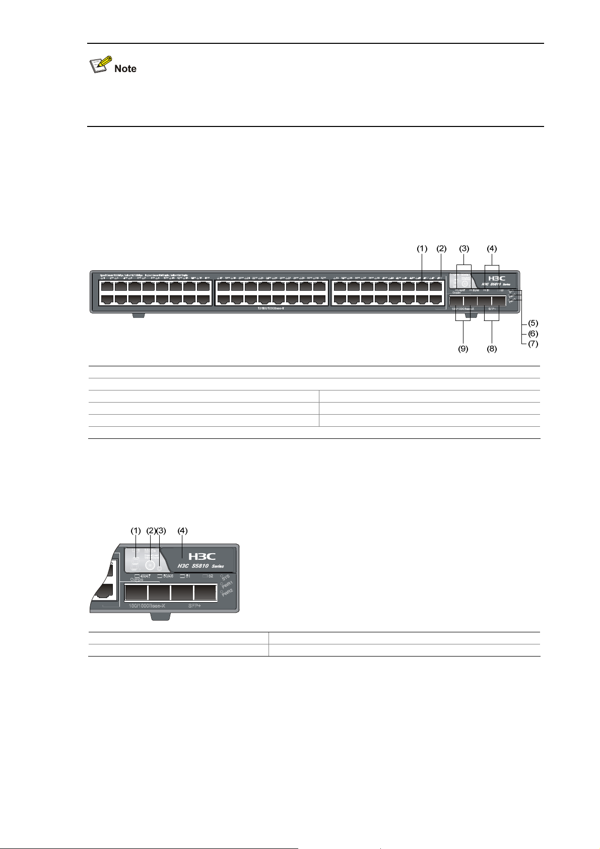
Figure 1-1 S5810-50S front panel
(1) 10/100/1000Base-T auto-sensing Ethernet port
(2) 10/100/1000Base-T auto-sensing Ethernet port status LED
(3) 100/1000Base-X SFP interface status LED (4) SFP+ interface status LED
(5) System LED (SYS) (6) Power module 1 status LED (PWR1)
(7) Power module 2 status LED (PWR2) (8) 10 GE SFP+ interface
(9) 100/1000Base-X SFP interface
The top right area on the front panel of the S5810-50S switch is the management area. The
management area provides LEDs and ports used for management and maintenance.
Figure 1-2 Management area of the S5810-50S switch
(1) Seven-segment LED (2) Mode switching button of the port status LED
(3) Port mode LED (4) Logo panel
After pulling out the logo panel, you can manage and maintain the switch through console port or USB
interface.
1-2
Page 9
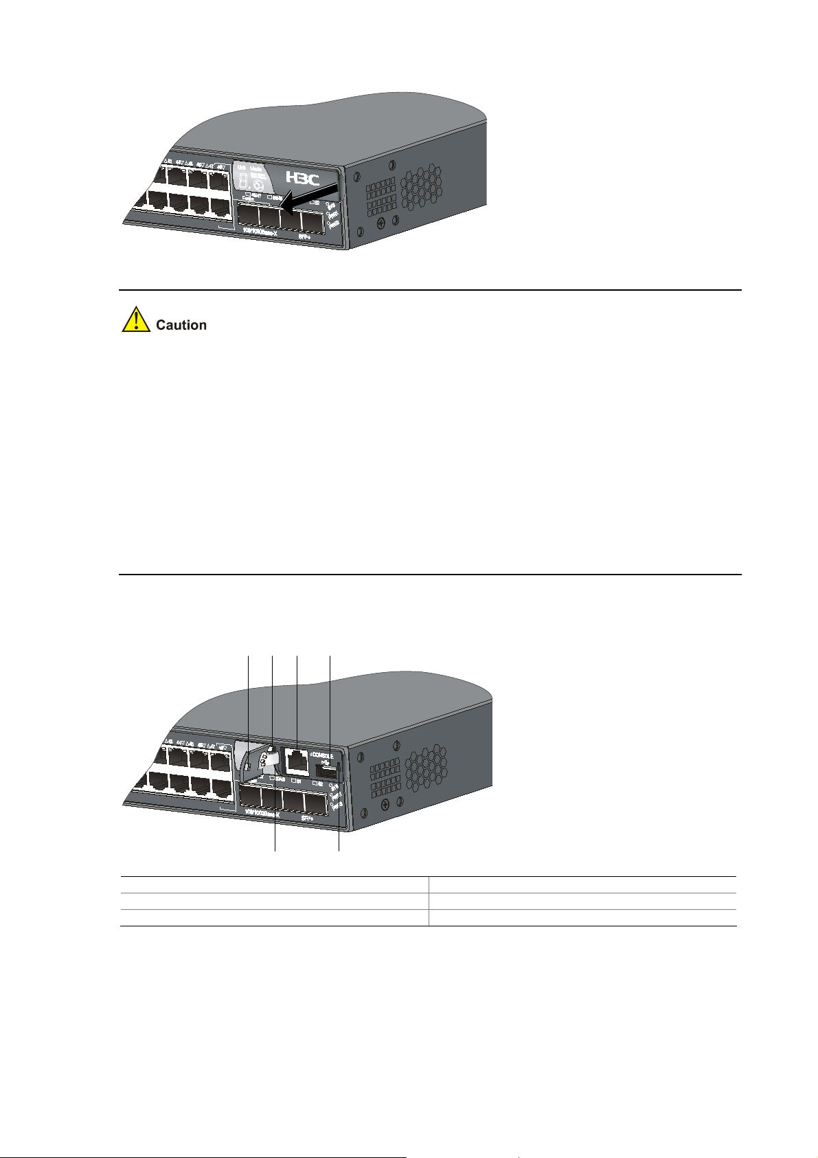
Figure 1-3 Logo panel of the S5810 series I
To pull out and push in the logo panel, follow these steps:
z Use your fingertip to hold the arc notch at the right edge of the logo panel, and then pull the panel
out with appropriate strength. Do not try to pull from any other part of the logo panel.
z The left part of the logo panel is attached to the chassis through a rubber strip. You can rotate the
strip or turn the logo panel over within the allowed elasticity of the rubber strip. Do not pull out the
strip rudely or turn over the panel excessively; otherwise, the rubber strip may fall off or be broken.
z Before pushing in the logo panel, make sure that the pin on the left side of the logo panel is inserted
in the corresponding recess of the chassis. Then clip the right side of the panel to the
corresponding recess of the chassis, and push the logo panel until the clip is locked to the chassis.
If the clip is not inserted in the recess, do not push the panel; otherwise the clip may be broken.
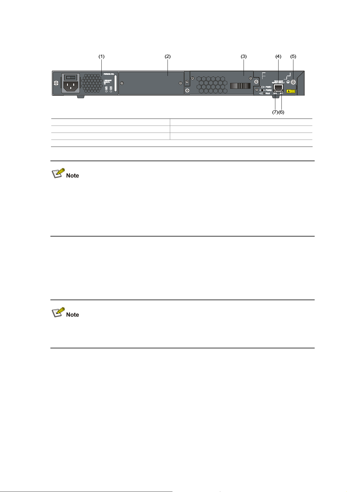
Figure 1-4 Logo panel of the S5810 series II
(1) (2) (3) (4)
(5)(6)
(1) Clip of the logo panel (2) Pin of the logo panel
(3) Console port (4) USB interface
(5) Position hole on the front panel (6) Rubber strip
1-3
Page 10
Rear Panel
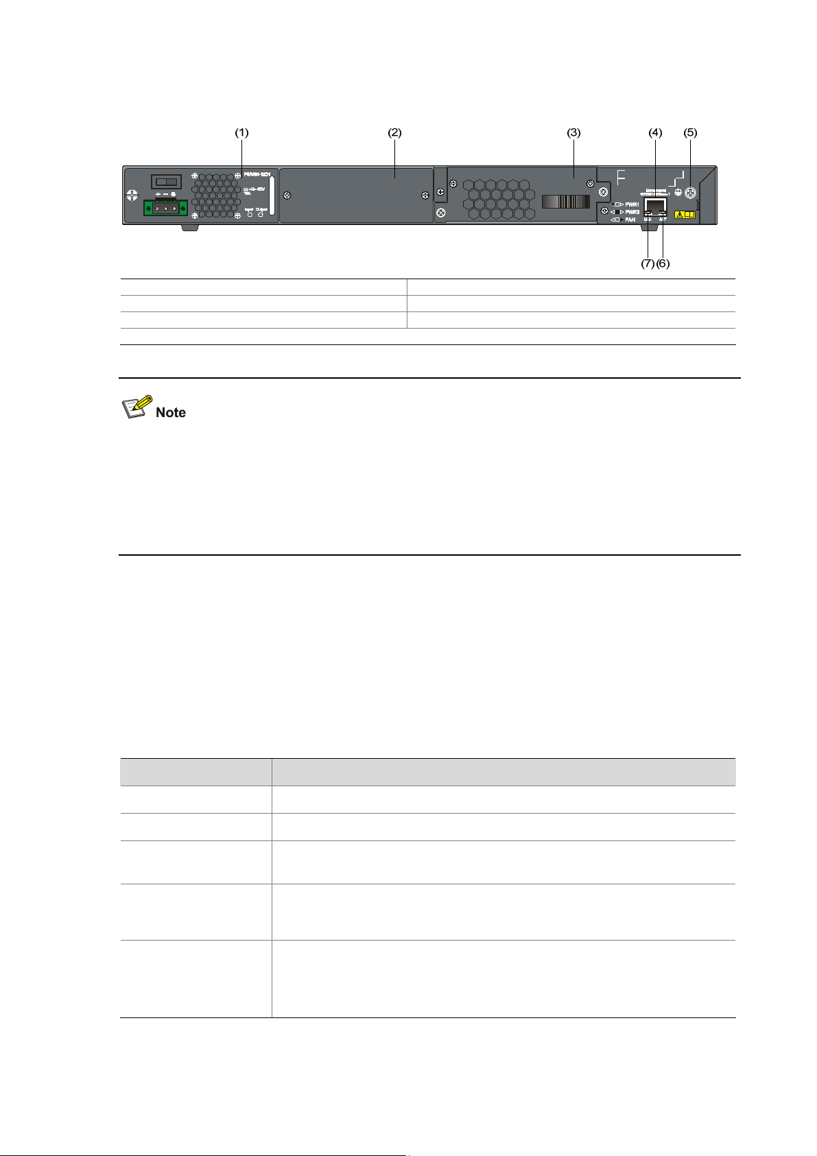
Figure 1-5 S5810-50S rear panel
(1) AC power module 1 (2) Power module slot 2
(3) Fan tray (4) Management Ethernet port
(5) Grounding screw (6) Management Ethernet port status LED (ACT)
(7) Management Ethernet port status LED (LINK)
The S5810-50S provides a PSR300-12A AC power module when shipped. Power module 2 is installed
with a filler panel. You can select two power modules to implement 1+1 power supply redundancy. See
Pluggable Power Modules on page 1-13 for the power module models supported by the S5810 series.
See H3C PSR300-12A & PSR300 -12D1 Power Modules User Manual for the detailed description of the
power modules.
S5810-50S-DC
Front Panel
The front panel of the S5810-50S-DC is the same as that of the S5810-50S. For related description,
refer to
Front Panel on page 1-2.
1-4
Page 11
Rear Panel
Figure 1-6 S5810-50S-DC rear panel
(1) DC power module 1 (2) Power module slot 2
(3) Fan tray (4) Management Ethernet port
(5) Grounding screw (6) Management Ethernet port status LED (ACT)
(7) Management Ethernet port status LED (LINK)
The S5810-50S-DC provides a PSR300-12D1 DC power module when shipped. Power module 2 is
installed with a filler panel. You can select two power modules to implement 1+1 power supply
redundancy. See
the S5810 series. See H3C PSR300-12A & PSR300-12D1 Power Module User Manual for the detailed
description of the power modules.
Ports
Console Port
Each S5810 series provides one console port on the front panel. Table 1-2 describes the console port
specifications.
Table 1-2 Console port specifications
Connector type
Compliant standard
Pluggable Power Modules on page 1-13 for the power module models supported by
Item Specification
RJ-45
EIA/TIA-232
Transmission baud
rate
Service
Default connection
parameters
9600 bps to 115200 bps
z It can be connected to an ASCII terminal.
z It can be connected to a serial port of a local or remote (through a pair of
modems) PC running terminal emulation program.
z Baud rate: 9600 bps
z Data bits: 8
z Parity check: none
z Stop bits: 1
1-5
Page 12

Management Ethernet Port
The S5810 series provides a management Ethernet port, which connects to a computer to perform
system program loading and debugging without being affected by the switching chip working status; or
the management Ethernet port can be connected to a remote NMS to implement remote management
of the system.
Table 1-3 S5810 management Ethernet port specifications
Item Specification
Connector type RJ-45
Connector quantity 1
Port transmission rate 10/100/1000 Mbps half duplex, full duplex
Transmission medium and
maximum transmission distance
Function and service Host software, Boot ROM upgrade, and network management
USB Interface
Each S5810 series provides a USB interface compliant with the OHC standard, supporting an upload
and download speed of 12 Mbps. With this USB interface, you can access the file system on the flash of
the switch to upload or download application and configuration files.
10/100/1000Base-T Ethernet Port
Each S5810 series provides forty-eight 10/100/1000Base-T Ethernet ports on its front panel. Table 1-4
describes the specifications of the 10/100/1000Base-T Ethernet ports.
Table 1-4 S5810 series 10/100/1000Base-T Ethernet port specifications
Item Specification
Connector type
Category-5 twisted pair cable, with a maximum transmission
distance of 100 m (328.1 ft.)
RJ-45
Interface standard
Max transmission distance
Transmission medium
Standard
100/1000Base-X SFP Interface
Each S5810 series provides two 100/1000Base-X SFP interfaces on its front panel. Each SFP interface
and its corresponding Ethernet port form a combo port group. Only one port is available in a combo port
group at one time.
Table 1-5 describes the combo port groups.
z 10 Mbps half duplex, full duplex
z 100 Mbps half duplex, full duplex
z 1000 Mbps half duplex, full duplex
z MDI/MDI-X, auto-sensing
100 m (328.1 ft.)
Category-5 unshielded twisted pair cable
IEEE 802.3i, 802.3u, 802.3ab
1-6
Page 13

Table 1-5 Combo port groups of the S5810 series
Combo port group SFP interface number Ethernet port number
1 49 47
2 50 48
Table 1-6 describes the 100/1000Base-X SFP interface specifications.
Table 1-6 S5810 series 100/1000Base-X SFP interface specifications
Item Specification
Connector type
LC (for SFP optical interface module)/RJ-45 (for SFP electrical interface
module)
Work mode Supports full duplex mode
Optical module
attribute
The SFP optical module is hot swappable. The specifications vary by the SFP
module models. For details, refer to
You can select SFP modules listed in
Table 1-7 as needed.
Table 1-7 SFP modules supported by SFP interfaces
SFP
modul
e type
SFP module
Central
wavelength
SFP-GE-SX-MM850-A 850nm
SFP-GE-LX-SM1310-A
1310nm
1000
SFP-GE-LH40-SM1310
Mbps
SFP
modul
e
SFP-GE-LH40-SM1550
1550nm
SFP-GE-LH70-SM1550
Table 1-7.
Connector Fiber
50/125µm
multimode
optical fiber
62.5/125µm
multimode
optical fiber
LC
9/125µm single
mode optical
fiber
Max
transmissi
on distance
550 m
(1804.5 ft.)
275 m
(902.2 ft.)
10 km (6.2
mi.)
40 km (24.9
mi.)
40 km (24.9
mi.)
70 km (43.5
mi.)
SFP-GE-LX-SM1310-BID
I
SFP-GE-LX-SM1490-BID
I
SFP-GE-T — RJ-45
TX: 1310
RX: 1490
TX: 1490
RX:1310
1-7
LC
9/125µm single
mode optical
fiber
Twisted pair
cable
10 km (6.2
mi.)
100 m
(328.1 ft.)
Page 14
SFP
modul
e type
100
Mbps
SFP
modul
e
SFP module
Central
wavelength
SFP-FE-SX-MM1310-A
SFP-FE-LX-SM1310-A
1310nm
SFP-FE-LH40-SM1310
SFP-FE-LH80-SM1550 1550nm
SFP-FE-LX-SM1310-BIDI
SFP-FE-LX-SM1550-BIDI
TX: 1310
RX: 1550
TX: 1310
RX: 1550
Connector Fiber
62.5/125µm
multimode
optical fiber
9/125µm single
mode optical
fiber
LC
9/125µm single
mode optical
fiber
9/125µm single
mode optical
fiber
9/125µm single
LC
mode optical
fiber
Max
transmissi
on distance
2 km (1.2
mi.)
15 km (9.3
mi.)
40 km (24.9
mi.)
80 km (49.7
mi.)
15 km (9.3
mi.)
z You are recommended to use SFP optical modules of H3C on the S5810 series.
z The types of SFP optical modules may update with time. For information about SFP modules,
contact technical support.
z For the models and specifications of each kind of optical modules, refer to H3C Low End Series
Ethernet Switches Pluggable Modules Manual.
SFP+ Interface
Each S5810 series provides two fixed SFP+ interfaces on its front panel. You can connect SFP+
modules or SFP+ cables to the SFP+ interfaces as needed to enhance the network flexibility.
describes the specifications of the 10G SFP modules and SFP+ cables.
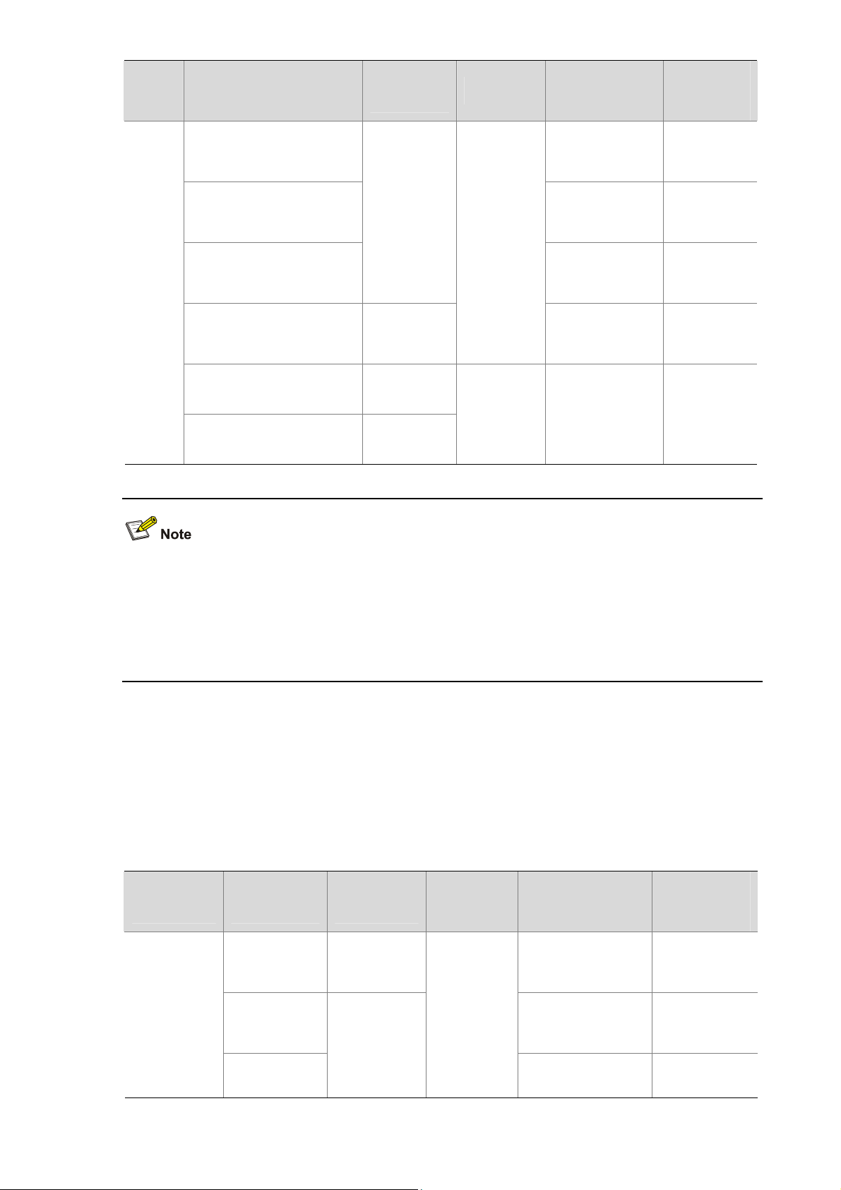
Table 1-8 Transceivers and cables supported by SFP+ interfaces
Transceiver/
Cable type
Transceiver/
Cable
SFP-XG-SXMM850-A
Central
wavelength
850nm
Connector Fiber
50/125µm
multimode optical
fiber
Table 1-8
Max
transmission
distance
300 m (984.3
ft.)
10G SFP+
transceiver
SFP-XG-LX2
20-MM1310
SFP-XG-LXSM1310
1310nm
1-8
LC
62.5/125µm
multimode optical
fiber
9µm/125µm single
mode optical fiber
220 m (721.8
ft.)
10 km (about
6.2 mi.)
Page 15
Transceiver/
Cable type
Transceiver/
Cable
Central
wavelength
Connector Fiber
LSWM1STK 0.65 m (2.1 ft.)
Short-haul
10G SFP+
cable
LSWM2STK 1.2 m (3.9 ft.)
—
1X
Infiniband
SFP+ cable
LSWM3STK
H3C provides three types of SFP+ cables with various lengths, as shown in
Figure 1-7 SFP+ cable
Max
transmission
distance
3 m (9.8 ft.)
Figure 1-7.
z You are recommended to use SFP+ transceivers of H3C on the S5810 series.
z The types of SFP+ transceivers may update with time. For information about transceivers, contact
z For the models and specifications of each kind of transceivers, refer to H3C Low End Series
LEDs
Table 1-9 LEDs
(1) Connector (2) Handle
technical support.
Ethernet Switches Pluggable Modules Manual.
LED Description
System status LED See System LED on page 1-10.
Hot swappable power module LED See Power Module Status LEDs on page 1-10.
Seven-segment LED See Seven-Segment LED on page 1-10.
Port mode LED See Port Mode LED on page 1-11.
10/100/1000Base-T auto-sensing Ethernet
port status LED
100/1000Base-X SFP interface status LED
See 10/100/1000Base-T Auto-Sensing Ethernet Port
Status LED on page
See
100/1000Base-X SFP Interface Status LED on
1-12.
page
1-9
1-11.
Page 16

LED Description
SFP+ interface status LED See SFP+ Interface Status LED on page 1-13.
Management Ethernet port status LED
System LED
Table 1-10 System LED description
LED Status Description
Steady green The switch is started normally.
Flashing green (1 Hz) The system is performing POST.
SYS
Steady red POST failed.
Flashing yellow (1 Hz) POST on some ports failed.
Off The switch is powered off.
Power Module Status LEDs
See
Management Ethernet Port Status LED on page
1-13.
Table 1-11 Description of the LEDs
Mark Status Status
PWR1
PWR2
Seven-Segment LED
The seven-segment LED and the system LED together indicate the operating status of the device. For
details, refer to
Table 1-12.
Steady green
Steady yellow
Off
Steady green
Steady yellow
Off
Hot swappable power module slot 1 is installed with a power
module, and the power input is normal.
Hot swappable power module slot 1 is installed with a power
module, but an output failure occurs.
No power module is installed in hot swappable power module
slot 1, or no power is input.
Hot swappable power module slot 2 is installed with a power
module, and the power input is normal.
Hot swappable power module slot 2 is installed with a power
module, but an output failure occurs.
No power module is installed in hot swappable power module
slot 2, or no power is input.
Table 1-12 Seven-segment LED description
Status
Mark
Unit
System LED
(SYS) status
Flashing green The LED displays the specific POST running. The LED
Seven-segment LED status
Description
1-10
Page 17

Status
Mark
System LED
(SYS) status
Seven-segment LED status
Description
numbers one by one. displays the POST test ID.
Flashing red
Flashing green
Steady red
Steady red
Steady green
The LED flashes the specific
numbers.
A bar rotates clockwise
around the LED.
The LED displays F.
The LED displays t.
The LED displays C.
The LED displays S.
The LED displays c.
POST failed. The LED flashes
the POST test ID of the failed
test.
Software loading
Fan failure
Over-temperature alarm
The current switch is the
command switch in the cluster.
The current switch is a member
switch in the cluster.
The current switch is a
candidate switch in the cluster.
The LED displays the specific
numbers.
Port Mode LED
Table 1-13 Port mode LED description
LED Status Description
Steady green Indicates port rate.
Mode
Steady yellow Indicates port duplex mode.
10/100/1000Base-T Auto-Sensing Ethernet Port Status LED
The port mode LED and the 10/100/1000Base-T auto-sensing Ethernet port status LED together
indicate the port operation status, as shown in
Table 1-14.
The member ID of the current
switch.
1-11
Page 18

Table 1-14 10/100/1000Base-T auto-sensing Ethernet port LEDs description
Status
Port mode
LED
Ethernet port
status LED
Meaning
The port operates at the rate of 1000 Mbps; the LED is fast
Steady green
flashing when data is being sent and/or received on the
port.
Steady green
(rate mode)
Yellow
Flashing yellow (3
Hz)
fast flashing when data is being sent and/or received on the
port.
Power-on self test (POST) failed on the port.
Off No link is present on the port.
The port operates in full-duplex mode; the LED is fast
The port operates at the rate of 10/100 Mbps; the LED is
Steady green
flashing when data is being sent and/or received on the
port.
The port operates in half-duplex mode; the LED is fast
Steady yellow
(duplex mode)
Yellow
Flashing yellow (3
Hz)
flashing when data is being sent and/or received on the
port.
POST failed on the port.
Off No link is present on the port.
100/1000Base-X SFP Interface Status LED
Table 1-15 100/1000Base-X SFP interface status LEDs description
Interface
mode LED
Steady green
(rate mode)
Steady yellow
(duplex mode)
Status
SFP interface
Meaning
status LED
Off No link is present on the interface.
The interface operates at the rate of 1000 Mbps; the LED
Steady green
fast flashes when data is being sent and/or received on the
interface.
The interface operates at the rate of 100 Mbps; the LED
Steady yellow
fast flashes when data is being sent and/or received on the
interface.
Flashing yellow (3
Hz)
POST failed on the interface.
Off No link is present on the interface.
The interface operates in full duplex mode; the LED fast
Steady green
flashes when data is being sent and/or received on the
interface.
Flashing yellow (3
Hz)
POST failed on the interface.
1-12
Page 19

SFP+ Interface Status LED
The port mode LED and the SFP+ status LED together indicate the SFP+ interface operation status, as
shown in
Table 1-16 SFP+ status LEDs description
Steady green
(rate mode)
Steady yellow
(duplex mode)
Table 1-16.
Port mode
LED
Status
Ethernet port status
Steady green
Flashing yellow (3 Hz) POST failed on the port.
Off No link is present on the port.
Steady green
Flashing yellow (3 Hz) POST failed on the port.
Meaning
LED
The port operates at the rate of 10 Gbps; the LED is fast
flashing when data is being sent and/or received on the
port.
The port operates in full-duplex mode; the LED is fast
flashing when data is being sent and/or received on the
port.
Off No link is present on the port.
Management Ethernet Port Status LED
Table 1-17 The S5810 management Ethernet port status LED description
Mark Status Description
Off The management Ethernet port is not connected.
LINK
Steady green The management Ethernet port operates at a rate of 10/100/1000 Mbps.
Off The management Ethernet port is not receiving or sending data.
ACT
Flashing
yellow
The management Ethernet port is receiving or sending data.
Pluggable Power Modules
The S5810 series provides two power module slots. A power module is shipped with the switch.
z A PSR300-12A AC power module is shipped with the S5810-50S
z A PSR300-12D1 DC power module is shipped with the S5810-50S-DC
The switch only requires one power module to ensure the normal operation of the whole system. You
can also select two power modules to implement 1+1 power module redundancy and load sharing.
When implementing 1+1 power module redundancy, you can hot plug a power module. To prevent
damage to the device and personal injury, follow the installation and removal procedures illustrated in
Figure 1-8 and Figure 1-9, respectively.
1-13
Page 20

Figure 1-8 Installation procedure
Install the
Install the
power module
power module
Figure 1-9 Removal procedure
Switch off the
Switch off the
power module
power module
AC Power Module
The S5810 series uses PSR300-12A as the AC power module. The specifications of PSR300-12A are
illustrated in
Table 1-18 PSR300-12A specifications
Rated voltage range 100 VAC to 240 VAC; 50/60 Hz
Max voltage range 90 VAC to 264 VAC; 47/63 Hz
Output voltage 12 V
Table 1-18.
Connect the
Connect the
power cord
power cord
Disconnect the
Disconnect the
power cord
power cord
Switch on the
Switch on the
power module
power module
Remove the
Remove the
power module
power module
Item Specifications
Max output current 25 A
Max output power 300 W
DC Power Module
The S5810 series uses the PSR300-12D1 as the DC power module. The specifications of
PSR300-12D1 are illustrated in
Table 1-19 PSR300-12D1 specifications
Rated voltage range –48 VDC to –60 VDC
Max voltage range –40.5 VDC to –72 VDC
Output voltage 12 V
Max output current 25 A
Max output power 300 W
Table 1-19.
Item Specifications
See H3C PSR300-12A & PSR300 -12D1 Power M od ule User M anual for the detailed description of the
power modules.
Ventilation System
The ventilation system of the S5810 series consists of the air vents at both sides of the chassis, the
turbo fan, and the power module fans. With the ventilation system, the heat generated from the chassis
and the power modules can be dissipated in time to ensure the system stability. When installing the
1-14
Page 21

S5810 series, select a proper location according to the ventilation design of your installation
environment.
The ventilation process of the S5810 series is shown in
Figure 1-10. Air goes in from the air vents at
both sides of the chassis, takes the heat generated from the chassis and the power modules, and then
goes out from the exhaust vents of the turbo fan and power modules. The chassis and power modules
use separate air channels for heat dissipation. Make sure that both air channels are free of obstruction.
Figure 1-10 Ventilation process of the S5810 series
(3) (4)
(2)
(2)
(1)
(1) Front panel (2) Air vents at both side of the chassis
(3) Air exhaust vent of the turbo fan (4) Air exhaust vents of the power modules
The turbo fan model supported by the S5810 series is LSWM1BFAN. The specifications of
LSWM1BFAN are illustrated in
Table 1-20.
Table 1-20 LSWM1BFAN specifications
Specification Description
Fan number 1
Fan speed 5000 R.P.M
Max airflow 41.65 CFM
Input voltage 12 V
Power consumption 24 W
Acoustics
Normal speed: 48.4 dB-A
Max speed: 59.7 dB-A
Operating temperature –10°C to +60°C (14°F to 140°F)
1-15
Page 22

Specification Description
Relative humidity (noncondensing) 5% to 90%
Storage temperature –40°C to +75°C (-40°F to +167°F)
Storage relative humidity
(noncondensing)
5% to 95%
You can judge whether the fan works normally by checking the system status LED and the
seven-segment LED (for details, refer to
how to replace a turbo fan, refer to
Table 1-12). If a failure occurs, replace the turbo fan in time (for
Fan Tray Failure). For detailed information about fan trays, refer to
H3C LSWM1FAN & LSWM1BFAN Installation Manual.
1-16
Page 23

2 Installation Preparations
Safety Precautions
To avoid any device impairment and bodily injury caused by improper use, observe these rules:
z Before cleaning the switch, plug out the power cord of the power module of the switch first. Do not
clean the switch with wet cloth or liquid.
z Do not place the switch near water or in a damp environment. Prevent water or moisture from
entering the switch chassis.
z Do not place the switch on an unstable case or desk. The switch might be damaged severely in
case of a fall.
z Ensure proper ventilation of the equipment room and keep the ventilation vents of the switch free of
obstruction.
z Connect the yellow-green protection grounding cable before power-on.
z Make sure that the operating voltage is in the range labeled on the power module of the switch.
z Do not open the chassis to avoid electrical shocks when the switch is operating or just when the
switch is powered off.
z When replacing hot-swappable power modules and fan trays, wear ESD-preventive gloves to
avoid damaging the units.
Installation Site
The S5810 series must be used indoors. You can mount the switch in a rack or on a workbench, but
make sure:
z Adequate clearance is reserved at the air inlet/exhaust vents for ventilation.
z The rack or workbench has a good ventilation system.
z The rack is sturdy enough to support the device and its accessories.
z The rack or workbench is well earthed.
To ensure normal operation and long service life of your switch, install it in an environment that meets
the requirements described in the following subsections.
Temperature/Humidity
You must maintain a proper temperature and humidity in the equipment room. Long-term high humidity
may lead to bad insulation, electricity leakage, mechanical property changes, and metal corrosion.
However, if the relative humidity is too low, captive screws may become loose as the result of
contraction of insulation washers and static electricity may be produced in a dry environment to
jeopardize the circuits on the device. A high temperature is the most undesirable condition, because it
accelerates the aging of insulation materials and thus significantly lowers reliability and service life of
the switch.
For the temperature and humidity requirements of different models, refer to
2-1
Table 1-1 on page 1-1.
Page 24

Cleanness
Dust is a hazard to the operating safety of your device. The dust accumulated on the chassis can be
adsorbed by static electricity and result in poor contact of metal connectors or metal contact points.
Especially when the indoor relative humidity is low, electrostatic adsorption is more likely to happen.
This can not only shorten the service life of your device but also cause communications failures. The
following table lists the dust concentration limit.
Table 2-1 Dust concentration limit in the equipment room
Substance Concentration limit (particles//m³)
Dust
≤ 3 x 10⁴ (no visible dust on the tabletop over three days)
Note: The dust diameter is greater than or equal to 5 μm.
Besides dust, there are rigorous limits on the content of harmful substances in the air that can
accelerate the corrosion and aging of metals, such as chloride, acid, and sulfide in the equipment room.
The equipment room must be protected against ingression of harmful gases such as SO
and Cl
. For specific requirements, see the following table.
2
Table 2-2 Harmful gas limits in the equipment room
Gas Maximum concentration (mg/m3)
SO
2
H2S 0.006
NH3 0.05
Cl2 0.01
Electromagnetic Susceptibility
0.2
, H2S, NH3,
2
The operation of your switch can be affected by external interferences, such as conducted emission by
capacitance coupling, inductance coupling, electromagnetic wave radiation, and common impedance
(including the grounding system) coupling, and leads (power cables, signaling cables and output wires).
To eliminate the interferences, pay attention to the following:
z As the AC power system is a TN system, use a single-phase three-wire power socket with a
protection earth (PE) to effectively filter interference from the power grid.
z Keep the device far away from radio transmitting stations, radar stations, and high-frequency
devices.
z Use electromagnetic shielding, for example, shielded interface cables, when necessary.
z Route interface cables only indoors to prevent signal ports from getting damaged by over-voltage
or over-current caused by lightning strikes.
Laser Safety
The S5810 series are Class 1 laser devices.
2-2
Page 25

When an optional interface module or SFP/SFP+ module on the S5810 series is operating, do not stare
into the optical port because the laser light emitted from the optical fiber may hurt your eyes.
Installation Tools
z Flat-blade screwdriver
z Phillips screwdriver
z ESD-preventive wrist strap
The installation tools are not shipped with the S5810 series.
2-3
Page 26

3 Installing a Switch
On a mounting screw of the chassis of the H3C series switches, there is a seal labeled with H3C. You
must keep it intact before asking the agent to maintain the switch. You must get the permission of the
local agent before you can open the chassis. Otherwise, you will be responsible for irreversible
damages caused by your operations.
Installing the Switch into a 19-Inch Rack Using Mounting Brackets
The S5810 series switches can be installed into a 19-inch rack with load-bearing mounting brackets.
Figure 3-1 show how to install an S5810 switch into a 19-inch rack.
Figure 3-1 Install an S5810 into a 19-inch rack
Choose proper installation
positions for mounting brackets
(Front, center, or rear mounting)
Introduction to Mounting Brackets
The S5810 series switches provides a pair of 1U mounting brackets as shown in Figure 3-2.
Figure 3-2 Mounting brackets of an S5810
Install the mounting
brackets to the left and
right sides of the switch
Mount the switch to
a rack
Attaching the Mounting Brackets to a Switch
The mounting brackets can be attached to a switch for center, front, or rear mounting. You can choose a
proper position according to the actual requirements.
1) Fix the left and right mounting brackets respectively to the left and right sides of the chassis.
Figure 3-4, and Figure 3-5 show how to install the brackets for front mounting, center mounting,
3-3,
3-1
Figure
Page 27

and rear mounting (because the installation procedures of the two brackets are the same, each
figure shows only how to install one bracket).
2) Fasten the M4x8 screws.
Figure 3-3 Attach the mounting bracket to an S5810 for front mounting
Figure 3-4 Attach the mounting bracket to an S5810 for center mounting
Figure 3-5 Attach the mounting bracket to an S5810 for rear mounting
Mounting the Switch to a Rack
1) Wear an ESD-preventive wrist strap and make sure the rack is well grounded and is firm enough to
hold the switch and cables.
2) Attach the mounting brackets to the switch. For details, refer to
a Switch.
3) Hold the bottom of the switch and gently place the switch on the rack to a proper location with one
person.
4) Fix the mounting brackets with screws (anti-rust screws prepared by yourself) with another person
to install the switch to the rack horizontally.
Attaching the Mounting Brackets to
3-2
Page 28

If support trays are provided on the rack, you can mount the switch to the rack with mounting brackets
and trays. Put the switch on the support tray and slide the switch to an appropriate place. Then fix the
mounting brackets.
Figure 3-6 Mount the S5810 to a rack
Mounting the Switch on a Workbench
In many cases, standard 19-inch cabinets are not available. Therefore, switches are often placed on
clean workbenches. To place the switch on a workbench, follow these steps:
3-3
Page 29

1) Place the switch with bottom up carefully, and then clean the round holes on the chassis bottom
with dry cloth.
2) Attach the rubber feet to the four round holes on the chassis bottom.
3) Place the switch with upside up on the workbench.
During the operation, you simply need to:
z Make sure that the workbench is flat and sturdy.
z Ensure good ventilation and a space of 10 cm (3.9 in.) around the chassis for heat dissipation.
z Do not place heavy objects on the switch.
Connecting the Ground Wire
z Correctly connecting the switch ground wire is crucial to the lightning protection and
electromagnetic susceptibility (EMS) of a switch.
z The power and grounding terminals in this section are for illustration only.
The power input end of the switch is connected with a noise filter, whose central ground is directly
connected to the chassis, forming the so-called chassis ground (commonly known as PGND). This
chassis ground must be securely connected to the earth so that the faradism and leakage electricity can
be safely released to the earth, enhancing the EMS capability of the switch.
The most common method is: Attach one end of the yellow-green ground wire of the switch to the
grounding screw on the grounding strip (the grounding screw and the grounding hole are on the rear
panel of the switch and are marked with a grounding sign). To do this, follow these steps:
1) Remove the grounding screw from the rear panel of the switch chassis.
2) Put the supplied OT terminal of the PGND cable on the grounding screw.
3) Fasten the grounding screw, which is attached with the OT terminal of the PGND cable, into the
grounding screw hole with a screwdriver.
3-4
Page 30

Figure 3-7 Connect the PGND cable to the grounding hole of switch
(1) Rear panel of the switch (2) Grounding sign
(3) Grounding hole (4) OT terminal
(5) PGND cable (6) Grounding screw
To attach the other end of the PGND cable to the grounding strip in the equipment room, follow these
steps:
1) Cut the PGND cable to a proper length according to the distance between the switch and the
grounding strip.
2) Peel 5 mm (0.2 in.) of insulation sheath using a wire stripper, and then insert the naked metal part
through the black insulation covering into the end of the OT terminal. (Two OT terminals are
provided with the PGND cable when shipped with the switch; select a proper OT terminal according
to the size of the grounding post.)
3) Secure the metal part of the cable to the OT terminal with a crimper, and then cover it with the
insulation covering. Then heat the insulation covering with a blowing machine to let it completely
cover the metal part.
4) Connect the OT terminal to the grounding pole of the grounding strip, and then fasten it with a hex
nut.
Figure 3-8 Connect the ground wire to the grounding strip
(1) Grounding post (2) Grounding strip
(3) PGND cable (4) Hex nut
3-5
Page 31

z Use the PGND cable provided with the switch to connect the grounding strip in the equipment room.
Otherwise, the switch may not be effectively grounded, which easily causes damage to the switch.
z If no grounding strip is available, refer to H3C S5810 S eries Ethernet Switches Installation Manual
for detailed grounding methods.
Installing a Power Module
The S5810 series provides two power module slots on its rear panel. Hot swappable power module slot
1 is empty when the switch is shipped, and hot swappable power module 2 is installed with a filler panel.
You can select one or two power modules for your switch as needed. For details about optional power
modules, refer to
The installation and removal procedure includes the installation and removal of power modules and
power cords. To prevent damage to the device and personal injury, follow the installation and removal
procedures illustrated in
Pluggable Power Modules on page 1-13.
Figure 3-9 and Figure 3-10, respectively.
Figure 3-9 Installation procedure
Install the
Install the
power module
power module
Connect the
Connect the
power cord
power cord
Figure 3-10 Removal procedure
Switch off the
Switch off the
power module
power module
Disconnect the
Disconnect the
power cord
power cord
Verifying the Installation
Before powering on the switch, check that:
z There is enough space for heat dissipation around the switch, and the rack or workbench is stable.
z The ground wire is connected.
z The selected power module matches that required by the switch.
z The power cables are properly connected.
z All the interface cables are cabled indoors. If there is any cable wired outdoors, verify that socket
strip with lightning protection and lightning arresters for network ports have been properly
connected.
Switch on the
Switch on the
power module
power module
Remove the
Remove the
power module
power module
3-6
Page 32

4 Initial Power-On
Setting Up the Configuration Environment
Set up the configuration environment as follows:
Connect a terminal (a PC in this example) to the console port on the switch with a console cable.
Figure 4-1 Network diagram for configuration environment setup
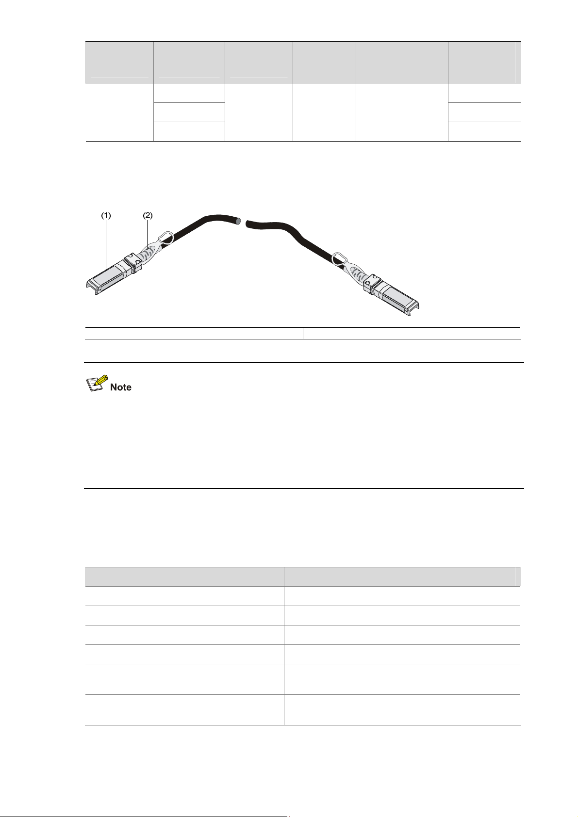
Connecting the Console Cable
Console Cable
A console cable is an 8-core cable. One end of the cable is a crimped RJ-45 connector, which is
connected to the console port of the switch, and the other end is a DB-9 female connector, which is
connected to the serial port on the console terminal, as shown below.
Figure 4-2 Console cable
Connection Procedure
When you want to use the terminal to configure the switch, follow these steps to connect a terminal
device to the switch using the console cable:
4-1
Page 33

1) Plug the DB-9 female connector of the console cable to the serial port of the PC or terminal where
the switch is to be configured.
2) Connect the RJ-45 connector of the console cable to the console port of the switch.
Pay attention to the mark on the console port and be sure to plug the connector to the right port.
z When connecting a PC to a powered-on switch, you are recommended to connect the DB-9
connector of the console cable to the PC before connecting the RJ-45 connector to the switch.
z When disconnecting a PC from a powered-on switch, you are recommended to disconnect the
DB-9 connector of the console cable from the PC after disconnecting the RJ-45 connector from the
switch.
Setting Terminal Parameters
1) Start the PC and run the terminal emulation program such as the Terminal of Windows 3.1 or the
HyperTerminal of Windows 2000/XP.
2) Set terminal parameters (take the HyperTerminal of Windows XP as an example) as follows:
z Bits per second: 9,600
z Data bits: 8
z Parity: None
z Stop bits: 1
z Flow control: None
z Emulation: VT100
The specific procedure is as follows:
3) Select Start > Programs > Accessories > Communications > HyperTerminal to enter the
HyperTerminal window, and then click
description interface appears, as shown below.
to establish a new connection. The connection
4-2
Page 34

Figure 4-3 Connection description of HyperTerminal
4) Type the name of the new connection in the connection description interface and click OK. The
following interface pops up. Select the serial port to be used from the Connect using drop-down
list.
Figure 4-4 Set the serial port used by the HyperTerminal connection
5) Click OK after selecting a serial port and the following interface pops up. On the interface, set Bits
per second to 9600, Data bits to 8, Parity to None, Stop bits to 1, and Flow control to None.
4-3
Page 35

Figure 4-5 Set the serial port parameters
6) Click OK after setting the serial port parameters and the system enters the following interface.
Figure 4-6 HyperTerminal window
Click Properties in the HyperTerminal window to enter the properties window. Click Settings to enter
the following properties setting window, set the emulation to VT100, and then click OK.
4-4
Page 36

Figure 4-7 Set terminal emulation in properties setting window
Booting the Switch
Checking before Power-On
Before powering on the switch, verify that:
z The power cable and grounding cable are properly connected.
z The power supply voltage is consistent with that required by the switch.
z The console cable is properly connected; the terminal (which can be a PC) used for configuration
has been started; and the configuration parameters have been set.
Powering On the Switch
The S5810 series have the same Boot ROM display style. This document uses the Boot ROM display of
S5810-50S as an example:
Starting......
************************************************************************
* *
* H3C S5810-50S BOOTROM, Version 103 *
* *
************************************************************************
Copyright (c) 2004-2008 Hangzhou H3C Technologies Co., Ltd.
Creation Date : Dec 15 2008,14:19:14
CPU Clock Speed : 750MHz
4-5
Page 37

Memory Size : 512MB
Flash Size : 256MB
CPLD Version : 000
PCB Version : Ver.A
Mac Address : 00E0FC005810
Press Ctrl-B to enter Extended Boot menu...1
The last line asks whether you want to enter the Boot Menu. The system waits one second for your
response.
z The system has two startup modes: normal startup and fast startup. The normal startup mode
takes a little longer time than the fast startup mode because of more self-test operations.
z By default, the system starts up in fast mode and the waiting time here is one second. If you set the
startup mode to normal, the waiting time is five seconds. For the setting of the startup mode, refer
to the next section.
z If you press Ctrl + B within one second, the Boot Menu is displayed:
BOOT MENU
1. Download application file to flash
2. Select application file to boot
3. Display all files in flash
4. Delete file from flash
5. Modify BootRom password
6. Enter BootRom upgrade menu
7. Skip current configuration file
8. Set BootRom password recovery
9. Set switch startup mode
0. Reboot
Enter your choice(0-9):
Table 4-1 describes the fields above.
Table 4-1 Description on the fields
Item Description
1. Download application file to flash Download the application file to the flash memory
2. Select application file to boot Select the application file to boot
3. Display all files in flash Display all files in the flash memory
4. Delete file from flash Delete files from the flash memory
5. Modify BootRom password Modify the Boot ROM password
4-6
Page 38

Item Description
6. Enter BootRom upgrade menu Enter the Boot ROM update menu
7. Skip current configuration file
Skip the current configuration file (this configuration is valid
once)
8. Set BootRom password recovery Restore the Boot ROM password
9. Set switch startup mode Set the startup mode of the switch
0. Reboot Restart the switch
z If you perform no operation or press a key other than Ctrl + B within one second, once the
remaining waiting time becomes zero, the system begins to automatically start up and the following
information is displayed:
Starting to get the main application file--flash:/S5810_RELEASE.bin!...........
.........................................................
The main application file is self-decompressing................................
...............................................................................
..........................................Done!
System is starting...
Board checking.....................................LSW158150S
Switch chip selftest......................................OK!
SDRAM fast selftest.................................NOT TEST!
Flash fast selftest.......................................OK!
PHY selftest..............................................OK!
CPLD selftest.............................................OK!
Please check port leds..............................finished!
The switch Mac is: 00E0-FC00-5810
User interface aux0 is available.
Press ENTER to get started.
The appearance of "Press ENTER to get started" indicates that the automatic startup of the switch is
completed.
Press Enter. The following prompt is displayed:
<H3C>
You can configure the switch now.
The H3C Series switches provide abundant command views. For detailed descriptions about the
configuration commands and CLI, refer to H3C S5810 Series Ethernet Switches Operation Ma nual and
H3C S5810 Series Ethernet Switches Command Manual.
4-7
Page 39

Changing the Boot Mode
By default, the system starts up in fast boot mode. If you want to change the boot mode to normal,
press Ctrl + B within one second to enter the Boot Menu showed below:
BOOT MENU
1. Download application file to flash
2. Select application file to boot
3. Display all files in flash
4. Delete file from flash
5. Modify BootRom password
6. Enter BootRom upgrade menu
7. Skip current configuration file
8. Set BootRom password recovery
9. Set switch startup mode
0. Reboot
Enter your choice(0-9):
Select 9, and the system prompts you to change the startup mode:
The current mode is fast startup mode!
Are you sure to change it to full startup mode? Yes or No(Y/N)
Enter Y. The system displays the following information:
Setting startup mode...done!
BOOT MENU
1. Download application file to flash
2. Select application file to boot
3. Display all files in flash
4. Delete file from flash
5. Modify BootRom password
6. Enter BootRom upgrade menu
7. Skip current configuration file
8. Set BootRom password recovery
9. Set switch startup mode
0. Reboot
Enter your choice(0-9):
Select 0. The system reboots in normal startup mode and displays the following information:
Starting......
************************************************************************
* *
* H3C S5810-50S BOOTROM, Version 103 *
* *
************************************************************************
Copyright (c) 2004-2008 Hangzhou H3C Technologies Co., Ltd.
4-8
Page 40

Creation Date : Dec 15 2008,14:19:14
CPU Clock Speed : 750MHz
Memory Size : 512MB
Flash Size : 256MB
CPLD Version : 000
PCB Version : Ver.A
Mac Address : 00E0FC005810
Press Ctrl-B to enter Extended Boot menu...5
In normal startup mode, the waiting time here is five seconds. If you press Ctrl + B within five seconds,
the Boot Menu is displayed. If you perform no operation or press a key other than Ctrl + B within five
seconds, the system begins to automatically start up and the following information is displayed:
Starting to get the main application file--flash:/S5810_release.bin............
The main application file is self-decompressing................................
...............................................................................
...............................................................................
...............................................................................
...............................................................................
..........................Done!
System is starting...
User interface aux0 is available.
Press ENTER to get started.
The appearance of "Press ENTER to get started" indicates that the automatic startup of the switch is
completed.
Press Enter. The following prompt is displayed:
<H3C>
You can configure the switch now.
The H3C Series switches provide abundant command views. For detailed descriptions about the
configuration commands and CLI, refer to H3C S5810 Series Ethernet Switches Operation Ma nual and
H3C S5810 Series Ethernet Switches Command Manual.
4-9
Page 41

5 Maintenance and Troubleshooting
Software Loading Failure
If software loading fails, the system runs steadily using the original system file. In this case, check
whether the physical ports are properly connected.
z If not, reconnect them correctly and restart the loading procedure.
z If so, view the loading procedure information displayed on the HyperTerminal to check for input
errors. If there is any input error, restart the loading procedure with correct input.
Common input errors include:
z Fail to set the baud rate of the HyperTerminal to 9,600 bps when loading the software at a baud
rate other than 9,600 bps through XMODEM.
z Enter an incorrect IP address, software name, or path of the TFTP server when using TFTP.
z Enter an incorrect IP address, software name, username, or password when using FTP.
If software loading fails when there are neither physical connection problems nor input errors, please
contact your agent for help.
Password Loss
User Password Loss
If you have forgotten the user password, you can enter the Boot Menu:
BOOT MENU
1. Download application file to flash
2. Select application file to boot
3. Display all files in flash
4. Delete file from flash
5. Modify BootRom password
6. Enter BootRom upgrade menu
7. Skip current configuration file
8. Set BootRom password recovery
9. Set switch startup mode
0. Reboot
Enter your choice(0-9):
Select 7, and then restart the switch. After the switch is restarted, the user password is removed.
Boot ROM Password Loss
Please contact with your sales agent.
5-1
Page 42

Power Supply Failure
You can check whether the power system of the switch fails by viewing the hot-swappable PWR1 or
PWR2 LED on the front panel and the LED on the power module. When the power supply system
functions normally, the corresponding LEDs should be ON. Otherwise, please check whether
z The switch power cable is properly connected.
z The power supply meets the requirement.
To replace the hot-swappable power module, refer to H3C S5810 Series Ethernet Switches Installation
Manual for detailed operation steps.
Fan Tray Failure
The fan tray do not have status LEDs. You can check the system LED and the seven-segment LED of
the device to determine whether the fan tray operates normally. If the fan tray fails, the two LEDs give an
indication, as shown in
Table 5-1 Fan tray fail LEDs description
LED Mark State
Table 5-1.
System LED SYS Steady red
Seven-segment LED Unit
Only when the system LED and the seven-segment LED are displayed as steady red and F respectively
does it indicate that a fan tray fails.
To replace the fan tray, refer to H3C S5810 Series Ethernet Switches Installation Manual for detailed
operation steps.
Configuration Terminal Failure
After the switch is powered on and the system is normal, the booting information will be displayed on the
configuration terminal. If the configuration system has any faults, there will not be any screen display at
the configuration terminal or the displayed characters will be totally illegible.
The LED displays F for fan failure.
Troubleshooting when there is no terminal display
If there is no output information after the configuration is powered on, please check whether:
z The power supply is normal
z The console cable is properly connected
If no problems are found after the above-mentioned items have been checked, the cause may lie in the
console cable or the settings of the terminal (such as hyper terminal) parameters. Please perform the
corresponding check.
5-2
Page 43

Troubleshooting when the terminal display is illegible
If there is illegible display at the configuration terminal, the cause might lie in the parameter setting error
at the terminal (such as HyperTerminal). Verify the following terminal parameter (such as hyper terminal)
settings:
z Baud rate: 9,600
z Data bits: 8
z Parity: none
z Stop bits: 1
z Flow control: none
z Emulation: VT100.
5-3
Page 44

Table of Contents
Appendix A Lightning Protection of the Switch·······················································································A-1
Installation of Lightning Arrester for AC Power (Socket Strip with Lightning Protection) ······················ A-1
Installation of Lightning Arrester for Network Port················································································· A-2
Appendix B Compliance and Safety Manual ···························································································· B-1
Regulatory compliance standards·········································································································· B-1
Regulatory compliance standards··································································································B-1
European Directives compliance···································································································· B-1
USA regulatory compliance············································································································ B-2
Canada regulatory compliance······································································································· B-2
Japan regulatory compliance ·········································································································B-3
CISPR 22 compliance ···················································································································· B-3
产品符合CLASS A 的声明 ··············································································································B-3
Safety Information Sicherheits informationen安全信息··········································································B-3
Overview Überblick 概述 ················································································································ B-3
Electricity Safety Elektrische Sicherheit 用电安全·········································································· B-7
Laser Laser激光辐射 ····················································································································B-10
i
Page 45

Appendix A Lightning Protection of the Switch
Installation of Lightning Arrester for AC Power (Socket Strip with Lightning Protection)
Lightning arrester will not be shipped with the switch. You should purchase it by yourself if needed.
If an outdoor AC power cord should be directly led to the switch, please serially connect the lightning
arrester for AC power (Socket Strip with Lightning Protection) before you plug AC power cord into the
switch, thus to prevent the possible damage to the switch due to lightning st rike. Y ou can use cable clips
and screws to fasten the lightning arrester for AC power on the cabinet, workbench or the wall of
equipment room.
Figure A-1 Diagram of lightning arrester
(1) Working LED (green)
(2) Grounding/pole detection LED
(red)
(3) Power switch
(4) IEC standard socket
(5) Overload automatic protector It can reset automatically.
(6) Multifunctional socket It is used to connect the power module of the device.
On means the circuit is working normally; off means the
circuit is damaged.
On indicates a wrong wire connection (the wire is not
grounded or the live line and null line are reversely
connected), and you need to check the power supply line.
It is used to connect to the power supply in the equipment
room through a power cord.
A-1
Page 46

z Make sure that the arrester is well grounded before using the lightning arrester for power.
z After inserting AC power cord plug of switch into the socket of lightning arrester, if the green LED is
on and the red LED does not alarm, it means that the lightning arrester of power is running an d the
function of lightning protection has taken effect.
z Pay adequate attention if the red LED is on. You should correctly locate the problem, whether it is
caused because the ground wire of the arrester is not well grounded or because the live and zero
wires are connected in reverse direction. You may check that in the following way. When the red
LED is on, use a multimeter to examine polarity at the power socket of the arrester. If it is same to
that of the power socket in the equipment room, it means that arrester is not well grounded. If it is
adverse to that of the power socket in the equipment room, it means that the power socket of the
arrester is set to the reverse polarity. In this case, you should open the power socket of arreste r to
correct polarity. After that, if the red LED still alarms, it means that the arrester is not well grounded
yet.
Installation of Lightning Arrester for Network Port
Lightning arrester for network port is specially designed for the Ethernet port of 10/100/1000M electrical
interface (RJ-45 connector is adopted in this case).
Lightning arrester for network port will not be provided along with the switch, and you sho uld purchase
it by yourself if needed.
If an outdoor network cable should be led to the switch, please se rially connect the lightning arrester for
network port before you plug this cable into the interface on the switch, in case of the possibility that the
switch may be damaged due to lightning strike.
Required tools
z Phillips screwdriver or Flat-blade screwdriver
z Multimeter
z Tilted wire cutter
Installation procedure
Step 1: Tear the protection paper at one side of the double faced adhesive tape a part from the tape, and
stick the tape on the surface of the arrester. Tear the protection paper at another side apart from the
tape, and stick the arrester onto the chassis of the switch. The arrester should be attached on the
chassis as close to the grounding screw as possible.
A-2
Page 47

Step 2: According to the distance to the grounding screw of the switch, cut the ground wire of the
arrester, and se curely tightening its ground wire to the grounding screw of the switch.
Step 3: Use the multimeter to measure whether the ground wire of the arrester contacts well with the
grounding screw of chassis.
Step 4: According to the instru ction of arrester for network port, connect the arrester with switch by the
cables (be carefully with the cable direction. Outdoor network cable should be inserted into the
arrester‘s IN end, and the cable connected to the switch should be inserted into t he arrester’s OUT end).
When you do that, observe whether the arrester indicators normally display.
The instruction of lightning arrester for network port contains the technical specifications, installation
and maintenance guide of the arrester. Please carefully read it before installing the arrester.
Step 5: Use the nylon ties to bundle the cables neatly.
Figure A-2 Installation diagram of lightning arrester for network port
Network cable indoors
Switch
Power input
Network cable led into from out d oor
Lightning arrester for network port
(attached onto the chassis)
Ground wire of lightning arrester
Grounding screw of switch
Metal cabinet that contains the switch
Installation precautions
Fully consider the following items in the installatio n process, otherwise, the pe rformance of the lightning
arrester for network port will be affected:
z Lightning arrester for network port is installed in reverse direction. In practice, the “IN” end should
be connected to the outdoor network cable and the “OUT” end to the network port on the switch.
z Lightning arrester for the network port is not well grounded. The ground wire for the arrester should
be as short as possible, so to ensure its good contact with the grounding screw of the switch. After
the connection, use the multimeter to confirm that.
z The lightning arrester for the network port is not installed completely. If the switch has more than
one network ports to interconnect with other devices via cable s outdoor, you should install lightning
arresters for all these network ports for protection.
A-3
Page 48

Appendix B Compliance and Safety Manual
Regulatory compliance standards
Regulatory compliance standards
Table B-1 Regulatory compliance standards
Discipline Standards
FCC Part 15 (CFR 47) CLASS A
ICES-003 CLASS A
VCCI-3 CLASS A
VCCI-4 CLASS A
CISPR 22 CLASS A
EN 55022 CLASS A
AS/NZS CISPR22 CLASS A
EMC
CISPR 24
EN 55024
EN 61000-3-2
EN 61000-3-3
EN 61000-6-1
ETSI EN 300 386
GB 9254
GB 17625.1
UL 60950-1
CAN/CSA C22.2 No 60950-1
IEC 60950-1
EN 60950-1/A11
Safety
AS/NZS 60950-1
EN 60825-1
EN 60825-2
FDA 21 CFR Subchapter J
GB 4943
European Directives compliance
LVD/EMC Directive
H3C S5810-50S product complies with the European Low Voltage Directive 2006/95/EC and EMC
Directive 2004/108/EC.
A copy of the signed Decl aration of Conformity can be downloaded from:
http://www.h3c.com/portal/Technical_Documents
B-1
Page 49

WEEE Directive–2002/96/EC
The products this manual refers to are covered by the Waste Electrical & Electronic Equipment (WEEE)
Directive and must be disposed of in a responsible manner.
USA regulatory compliance
FCC Part 15
H3C S5810-50S complies with Part 15 of the FCC Rules. Operation is subject to the following two
conditions:
z This device may not cause harmful interference.
z This device must accept any interference received, including interference that may cause
undesired operation.
If the customer modifies the equipment without the authorization of H3C, which directly or indirectly
contribute to the e quipme nt incom pliance with FCC require ment s for Cla ss A digital devices, Hangzhou
H3C Technologies Co.,Ltd is not liable for such interference problem and the expenses incurred
therefore shall be covered by the customers.
This equipment has been tested and found to comply with the limits for a Class A digital device,
pursuant to Part 15 of the FCC Rules. These limits are designed to provide reasonable protection
against harmful interference when the equipment is operated in a commercial environment. This
equipment generates, uses, and can radiate radio frequency energy and, if not installed and used in
accordance with the instruction manual, may cause harmful interference to radio communications.
Operation of this equipment in a residential area is likely to cause harmful interference in which case the
user will be required to correct the interference at his own expense.
FDA
H3C S5810-50S Conforms to the applicable requirements of 21 CFR Subchapter J
Canada regulatory compliance
ICES-003
This Class A digital apparatus complies with Canadian ICES-003.
Cet appareil numérique de la classe A est conforme à la norme NMB-003 du Canada.
B-2
Page 50

Japan regulatory compliance
VCCI
H3C S5810-50S complies with the requirements of VCCI Class A Information Technology Equipment
(ITE).
Warning: If this e quipment is used in a domestic environment, radi o disturbance may arise. When such
trouble occurs, the user may be required to take corrective actions.
CISPR 22 compliance
H3C S5810-50S complies with the requirements of CISPR 22 for Class A Information Technology
Equipment (ITE).
Warning: If this equipment is used in a domestic e nvironment, radio disturbance may arise. When such
trouble occurs, the user may be required to take corrective actions.
产品符合 CLASS A 的声明
此为 A级产品,在生活环境中,该产品可能会造成无线电干扰。在这种情况下,可能需要用户对其干扰
采取切实可行的措施。
Safety Information Sicherheits informationen
Overview Überblick 概述
This section introduces part of the safety precautions that should be followed during the in stallation and
maintenance of the equipment. And for the safety statements and warnings, there followed the
translations of both German and Chinese to comply with the national requirements.
Dieser Abschnitt macht Sie mit den Sicherheitsvorschriften vertraut, die Sie bei der Installation und
Instandhaltung der Ausrüstung beachten müssen.
本章节介绍了在安装、日常维护本系列设备时,必须遵循的安全预防规范。
安全信息
B-3
Page 51

Before any operation is performed, please read the operation instructions and precautions carefully to
minimize the possibility of accidents. The Note, Caution, Warning and Danger items in other manuals
do not cover all safety precautions that should be followed. They are only the supplements to the safety
precautions for operations as a whole. Therefore, the personnel in charge of the installation and
maintenance of the products are required to understand these basics of safety operation.
In performing various operations, please follow the local safety regulations. The safety precautions
introduced in the product manuals are supplementary and subject to the local safety regulations.
When various operations are executed on the products, the precautions and special safety instruction s
provided with the products must be followed to the full.
The personnel in charge of the installation and maintenance of the products must be trained as
professionals to master the proper operating methods and all safety precautions. Only the trained and
qualified personnel can perform operations such as equipment installation and maintenance.
Lesen Sie bitte alle Arbeitsanweisungen und Sicherheitvorschriften sorgfältig durch, bevor Sie mit dem
Arbeiten beginnen. Nur durch Beachtung dieser Hinweise lässt si ch das Unfall ri si ko minimie re n. Die in
anderen Handbüchern aufgeführten Symbole Anmerkung, Achtung, Warnung und Gefahr
beinhalten nicht alle zu beachtenden Sicherheitvorschriften. Sie dienen lediglich der Ergänzung.
Deshalb muss sich das für die Installation und Instandhaltung der A usrüstung verantwortliche Personal
mit allen Sicherheitshinweise vertraut machen.
Bei der Durchführung der verschiedenen Arbeitsschritte müssen außerdem die örtlichen
Sicherheitsvorschriften beachtet werden. Die in den Handbüch ern der einzelnen Produkte aufgef ührten
Sicherheitshinweise sind Ergänzungen und unterliegen den nationalen Sicherheitsvorschriften.
Während der Arbeit mit den Produkten sind deshalb grundsätzlich alle Sicherheitsvorschriften und
spezifischen Sicherheitshinweise genau zu beachten.
Das für die Installation und Instandhaltung der Produkte verantwortliche Pesonal muss geschult
werden, um alle Sicherheitsvorschriften zu kennen und die richtigen Arbeitsmethoden anwenden zu
können. Nur geschultes und qualifiziertes Personal kann die Installation und Instandhaltung in korrekter
Weise durchführen.
B-4
Page 52

为了避免可能发生的事故,请在进行任何操作前,仔细阅读设备操作手册和本章节的安全规范。手册中 出
现的说明、注意、警告、危险,不能涵盖所有的安全预防,仅仅是在整个操作过程中的安全提示和补充。
因此,负责安装和日常维护本设备的人员必须具备安全操作基本技能。
操作人员要按照当地的安全规范进行操作。出现在产品手册中的安全预防措施仅仅是当地安全规范的补
充。
在操作本设备时,请认真执行产品手册规定的安全规范。
设备安装、维护人员必须通过专业培训,并且掌握足够的操作技能和安规预防意识。只有专业人员才能
担任本设备的安装和维护工作。
Conventions Used Symbole Erläuterung 应用惯例
The symbols in this manual are shown in the following t able. They a re used to rem ind the rea der of the
safety precautions during equipment installation and maintenance.
Die Symbole in diesem Handbuch verwendeten sind in der folgenden Tabelle dargestellt. Diese
Symbole sollen das Personal während der Installation und Instandhaltung der Ausrüstung an die
Wichtigkeit der im Handbuch aufgeführten Sicherheitsvorschriften erin nern.
以下表格中的安全标识,是用来提示读者在进行设备安装和维护时的安全预防要求。
Table B-2 Safety symbol and description
Sicherheitssymbole und Beschreibung安全标识和描述
Safety Symbol
Symbole
安全标识
Generic alarm symbol: To suggest a general safety concern
Alarm: Hinweis auf ein generelles Sicherheitsproblem
一般注意标识:用于一般安全提示
ESD protection symbol: To suggest electrostatic-sensitive equipment.
ESD-Schutz: Hinweis auf Beschädigung infolge elektrostatischer Entladung
防静电标识:用于表示静电敏感的设备
Electric shock symbol: To suggest a danger of high voltage
Elektrischer Schlag: Hinweis auf Gefährdung durch Hochspannung
电击防护标识:用于表示高压危险
Laser symbol: To suggest a strong laser beam
Laser: Hinweis auf starken Laser
激光辐射标识:用于表示强激光辐射
Description
Erläuterung
描述
General Requirements Allgemeine Anforderungen 通用要求
In order to reduce the technically unavoidable residual risk to a minimum, it is imperative to follow the
rules below:
Um das technisch bedingte Restrisiko auf ein Minimum zu begre nzen, ist es unbedingt erfo rderlich, die
folgenden Regeln zu beachten:
为了避免对人和设备造成伤害,请认真执行下列要求:
B-5
Page 53

z Read all the instructions before operation.
z Lesen Sie alle Anweisungen sorgfältig durch, bevor Sie mit dem Arbeiten beginnen.
z 在进行操作前仔细阅读手册内容。
z When installing the unit, always make the ground connection first and disconnect it last.
z Beachten Sie, dass bei der Installation des Systems stets zuerst die Erdverbindung angebracht
wird und das die Erdverbindung stets als letztes getrennt wird.
z 进行设备安装时,必须确保接地连接是最先连接和最后断开。
z Do not block ventilation openings while the system is on, and keep at least 5 cm distance from
ventilation openings and walls or other things which may block the openings.
z Sorgen Sie dafür, dass die Öffnungen der Ventilation zu keinem Zeitpunkt verschlossen, verstopft
oder anderweitig blockiert sind. Zwischen den Ventilationsöffnungen und Wänden bzw. anderen
Gegenständen muss stets ein Abstand von mindestens 5cm bestehen.
z 设备在工作时必须确保通风口的畅通,确保设备离墙壁或是其它的可能堵塞通风口的物体的间距至
少 5cm。
z Never defeat the ground conductor or operate the equipment in the absence of a suitably installed
ground conductor. Contact the appropriate electrical inspection.
z Betreiben Sie die Ausrüstung niemals ohne Erdung. Trennen Sie das System nich t von der Erdung.
Kontaktieren Sie die entsprechende elektrische Kontrolle.
z 不允许破坏设备的接地导线或是在无接地连接的情况下操作设备,要进行适当的电气检查。
z The unit/system must be connected to the protection ground before operation permanently. And
2
the cross-section of protective earthing conductor shall be at least 1mm
z Das System muss vor der ständigen Inbetriebnahme geerdet werden. Der Querschnitt der
2
Erdverbindung sollte mindestens 1mm
z 进行设备/系统操作前,请确保永久接地,并且用于进行保护接地连接的接地线截面不小于 1mm
z For AC supplied model: The device applies to TN power systems.
z Mit Wechselstrom betriebenes Modell: Das Gerät arbeitet mit einem Phase-Nullleiter-System.
z AC 电源输入:此设备用于 TN 电源系统。
z For DC supplied model: Reinforced insulation must be provided to isolate 61-72V source from the
betragen.
.
2
。
AC mains supply.
z Mit Gleichstrom betriebenes Modell: Für das Gerät muss eine verstärkte Isolation bereitgestellt
werden, um die 61-72V-Quelle gegen die Hauptversorgung zu isolieren.
z DC 电源输入:61-72V 电源和 AC主输入之间的绝缘等级是加强绝缘。
z This product relies on the building’s installation for short-circuit (overcurrent) protection. It is
required to use a fuse or circuit breaker no larger than 120 VAC, 20A U.S. (240 VAC, 16A
international) or 80VDC, 50A.on the phase conductors (all current-carrying conductors).
z Dieses Produkt muss so installiert werden, dass es gegen Kurzschl uss (Überstrom) abgesichert ist.
Stellen Sie sicher, dass die Sicherungswerte auf allen Phasen ni cht größer al s 120VAC, 2 0A U.S.
(240VAC, 16A international) bei den mit Wechselstrom betriebenen Modellen sowie 80VDC, 50A.
bei den mit Gleichstrom betriebenen Modellen sind.
z 该产品需要使用建筑物安装来提供短路保护,要求保险丝或者短路保护器不小于 120 VAC, 20A U.S.
(240 VAC, 16A international) 或 80Vdc,50A。
z For AC supplied model: The plug-socket combination must be accessible at all times because it
serves as the main disconnecting device.
z Mit Wechselstrom betriebenes Modell: Der Netzstecker muss jederzeit leicht zugänglich sein.
Denn sie dient als wichtigstes Trennvorrichtung
B-6
Page 54

z AC 供电:插座必须随时可用,因为它是主要的切断电源装置。
z Because the device has several power supplies, disconnect all of them to switch off the device.
z Da das Gerät mehrere Energiequellen hat, ist es notwendig stets alle Verbindungen zu
unterbrechen, um den energiefreien Zustand zu erreichen.
z 因为设备存在多种电源输入,在关闭设备时确保切断所有电源连接。
z To prevent laser radiation from hurting your eyes, never stare into the open optical port.
z Nehmen Sie das Gerät nicht in Betrieb, solange das optische Fenster nicht geschlossen ist. Der
Laserstrahl kann zu Augenverletzungen führen.
z 为了避免光纤发出的高能量的激光光束伤害到视网膜,请不要直视光接口。
Electricity Safety Elektrische Sicherheit 用电安全
High Voltage Hochspannung 高电压
High voltage power supply offers electric power for equipment operation. Direct contact or indirect
contact (via damp objects) with high voltage and AC mains supply may result in fatal danger.
Die Hochspannungsleitungen stellen fü r die Arbeit der Ausrüstung erforderliche Energie zur Verfügung.
Direkter oder indirekter Kontakt (z. B. durch feuchte Gegenstände) mit Hochspannung und
Wechselstromversorgung kann zu tödlichen Unfällen führen.
高压电源为设备运行提供电能,直接或是间接(通过潮湿的物体)接触高压和 AC 交流电源输入,都会
导致致命危险。
z During the installation of AC power supply facility, the local safety regulations must be followed.
The personnel who install the AC facility must be qualified for high voltage and AC operations.
z Bei der Installation der Wechselstromversorgung sind die örtlichen Sicherheitsbestimmungen zu
beachten. Das Personal muss besonders qualifiziert sein für das Arbeiten mit Hochspannung und
Wechselstrom.
z 必须按照当地安全规定进行 AC 交流供电设备的安装。负责电源安装的人员必须是通过高压和电源
操作专业培训的专业人员。
z Conducting articles, such as watch, hand chain, bracelet and ring are prohibited during the
operation.
z Es ist nicht erlaubt während dieser Arbeiten leitende Gegenstände wie Uhren, Armbänder,
Armreifen und Ringe am Körper zu tragen.
z 在操作中不能穿戴导电性的物品,如:手表,手琏,手镯和项链等。
B-7
Page 55

z When water is found in the rack, or the rack is damp, please immediately switch off the power
supply.
z Sollte sich Wasser im Baugruppenträger befinden oder der Baugruppenträger feucht sein, ist die
Energiezufuhr sofort zu unterbrechen und das System abzuschalten.
z 当有液体进入机架或机架有损坏时,请立即切断电源。
z When operation is performed in a damp environment, make sure that water is kept off the
equipment.
z Muss in einem feuchten Umgebung gearbeitet werden, ist sicherzustellen, dass kein Wasser i n die
Ausrüstung dringen kann.
z 在潮湿环境下进行安装时,请避免液体进入设备。
Non-standard and improper high voltage operations may result in fire and electric shock. Therefore, AC
cable bridging and wiring through a certain area must follow the local rules and regulations. The
personnel who perform high voltage operations should be qualified for high voltage and A C operations.
Die Nichtbeachtung der Sicherheitsvorschriften bei der Arbeit mit Hochspannung kann zu Feuer und
elektrischem Schlag führen. Deshalb muss die Verlegung von Leitungen und Verbindungen den
örtlichen Anforderungen und Sicherheitsvorschriften entsprechen. Arbeiten mit Hochspannung dürfen
nur von qualifiziertem Fachpersonal durchgeführt werden.
不规范和不正确的高压电源操作,都会导致失火和电击危险。因此,必须由通过高压和 AC 电源操作专
业培训的专业人员按照当地电气安全规定配置线缆。
Power Cable Zuleitung 电缆
Installation and removal of live power cable is prohibited strictly. Transi ent conta ct between the co re of
power cable and conductor may generate electric arc or spark or electric arc, which may lead to fire or
eye injury.
B-8
Page 56

Das Entfernen und Anbringen von Zuleitungen ist strengstens verboten. Kurzschlüsse zwischen
innerem und äußerem Leiter können Lichtbögen oder Funkenflug verursachen, was zu Feuer oder
einer Augenverletzung führen kann.
禁止安装和移动带电的线缆。因为导电体和带电的线缆,即使短暂接触,也会引起电火花或电弧,从而
导致失火或是伤害眼睛。
z Before the power cable is installed or removed, the power switch must be turned off.
z Das System muss stets abgeschaltet werden, bevor die Zuleitung angebracht oder entfernt wird.
z 在安装、移动线缆之前,请切断电源。
z Before the power cable is connected, it must be confirmed that the power cable and label comply
with the requirements of the actual installation.
z Überprüfen Sie vor dem Anbringen der Zuleitung immer, ob das von Ihnen verwendete Kabel den
Anforderungen entspricht.
z 在进行线缆连接前,请确认线缆和线缆的标识与实际安装要求是一致的。
For DC power supplied equipment, please use 1mm2 or 16AWG minimum power supply cord.
For AC power supplied equipment, please use 0.75mm
2
or 18AWG minimum power supply cord.
Für mit Gleichstrom betriebene Ausrüstung benutzen Sie bitte eine Mindest-1mm2 oder 16AWG
Zuleitung.
Für mit Wechselstrom betriebene Ausrüstung benutzen Sie bitte eine Mindest-0.75mm
2
oder 18AWG
Zuleitung.
DC 电源设备,请使用 1mm2 或 16AWG电缆;
AC 电源设备,请使用 0.75mm
2
或 18AWG电缆。
B-9
Page 57

Thunderstorm Gewitter 防雷击
High voltage and AC operations or operations on a steel tower and a mast on a thunderstorm day are
prohibited. In order to prevent the equipment from being damaged by lightning, proper grounding is
required.
Arbeiten mit Hochspannung und Wechselstrom oder Arbeiten auf Stahltürmen und masten während
eines Gewitters sind verboten. Um die Ausrüstung vor Beschädigung durch Blitzschlag zu schützen, ist
eine ordnungsgemäße Erdung erforderlich.
禁止在雷雨天进行高压电源和 AC 交流电源安装操作,对金属架和天线的操作也是不允许的。为保护设
备免遭雷击破坏,设备应可靠接地。
Laser Laser 激光辐射
The laser hazard level of this equipment is Class 1.
Die von diesem Laser ausgehende Gefahr entspricht der Kateg orie 1.
本设备的激光防护等级是 1 类
When performing installation and maintenance operations of optical fibers, you should not stand close
to, or look into the optical fiber outlet directly with unaided eyes.
Während der Installation und Instandhaltung der optischen Fasern dürfen Sie nicht zu nahe am
Ausgang der optischen Fasern stehen und nicht ohne Augenschutz in die optischen Fasern sehen.
在安装和维护设备的光纤接口时,请不要把眼睛靠近或是直视这些光接口。
B-10
 Loading...