

Page 1

Operation Manual – Multicast
H3C S5500-EI Series Ethernet Switches Table of Contents
Table of Contents
Chapter 1 Multicast Overview......................................................................................................1-1
1.1 Introduction to Multicast.....................................................................................................1-1
1.1.1 Comparison of Information Transmission Techniques............................................1-1
1.1.2 Roles in Multicast....................................................................................................1-4
1.1.3 Advantages and Applications of Multicast .............................................................. 1-5
1.2 Multicast Models................................................................................................................1-6
1.3 Multicast Architecture ........................................................................................................1-6
1.3.1 Multicast Addresses................................................................................................1-7
1.3.2 Multicast Protocols................................................................................................ 1-11
1.4 Multicast Packet Forwarding Mechanism........................................................................1-13
Chapter 2 IGMP Snooping Configuration ................................................................................... 2-1
2.1 IGMP Snooping Overview ................................................................................................. 2-1
2.1.1 Principle of IGMP Snooping....................................................................................2-1
2.1.2 Basic Concepts in IGMP Snooping.........................................................................2-2
2.1.3 Work Mechanism of IGMP Snooping......................................................................2-4
2.1.4 Processing of Multicast Protocol Messages ...........................................................2-6
2.1.5 Protocols and Standards.........................................................................................2-6
2.2 IGMP Snooping Configuration Task List ........................................................................... 2-7
2.3 Configuring Basic Functions of IGMP Snooping ............................................................... 2-8
2.3.1 Configuration Prerequisites.....................................................................................2-8
2.3.2 Enabling IGMP Snooping........................................................................................2-8
2.3.3 Configuring the Version of IGMP Snooping............................................................ 2-9
2.4 Configuring IGMP Snooping Port Functions...................................................................... 2-9
2.4.1 Configuration Prerequisites.....................................................................................2-9
2.4.2 Configuring Aging Timers for Dynamic Ports........................................................2-10
2.4.3 Configuring Static Ports ........................................................................................ 2-11
2.4.4 Configuring Simulated Joining .............................................................................. 2-12
2.4.5 Configuring Fast Leave Processing......................................................................2-13
2.5 Configuring IGMP Snooping Querier...............................................................................2-14
2.5.1 Configuration Prerequisites...................................................................................2-14
2.5.2 Enabling IGMP Snooping Querier......................................................................... 2-14
2.5.3 Configuring IGMP Queries and Responses..........................................................2-15
2.5.4 Configuring Source IP Address of IGMP Queries.................................................2-16
2.6 Configuring an IGMP Snooping Policy............................................................................2-17
2.6.1 Configuration Prerequisites...................................................................................2-17
2.6.2 Configuring a Multicast Group Filter......................................................................2-17
2.6.3 Configuring Multicast Source Port Filtering........................................................... 2-18
i
Page 2

Operation Manual – Multicast
H3C S5500-EI Series Ethernet Switches Table of Contents
2.6.4 Configuring the Function of Dropping Unknown Multicast Data...........................2-19
2.6.5 Configuring IGMP Report Suppression................................................................. 2-20
2.6.6 Configuring Maximum Multicast Groups that Can Be Joined on a Port................ 2-20
2.6.7 Configuring Multicast Group Replacement ........................................................... 2-21
2.7 Displaying and Maintaining IGMP Snooping...................................................................2-23
2.8 IGMP Snooping Configuration Examples........................................................................ 2-23
2.8.1 Configuring Simulated Joining .............................................................................. 2-23
2.8.2 Static Router Port Configuration ........................................................................... 2-26
2.8.3 IGMP Snooping Querier Configuration.................................................................2-29
2.9 Troubleshooting IGMP Snooping Configuration..............................................................2-31
2.9.1 Switch Fails in Layer 2 Multicast Forwarding........................................................2-31
2.9.2 Configured Multicast Group Policy Fails to Take Effect........................................2-32
Chapter 3 MLD Snooping Configuration..................................................................................... 3-1
3.1 MLD Snooping Overview................................................................................................... 3-1
3.1.1 Introduction to MLD Snooping.................................................................................3-1
3.1.2 Basic Concepts in MLD Snooping...........................................................................3-2
3.1.3 How MLD Snooping Works..................................................................................... 3-4
3.1.4 Protocols and Standards.........................................................................................3-6
3.2 MLD Snooping Configuration Task List............................................................................. 3-6
3.3 Configuring Basic Functions of MLD Snooping.................................................................3-7
3.3.1 Configuration Prerequisites.....................................................................................3-7
3.3.2 Enabling MLD Snooping ......................................................................................... 3-7
3.3.3 Configuring the Version of MLD Snooping..............................................................3-8
3.4 Configuring MLD Snooping Port Functions.......................................................................3-8
3.4.1 Configuration Prerequisites.....................................................................................3-8
3.4.2 Configuring Aging Timers for Dynamic Ports..........................................................3-9
3.4.3 Configuring Static Ports ........................................................................................ 3-10
3.4.4 Configuring Simulated Joining .............................................................................. 3-10
3.4.5 Configuring Fast Leave Processing......................................................................3-11
3.5 Configuring MLD Snooping Querier.................................................................................3-12
3.5.1 Configuration Prerequisites...................................................................................3-12
3.5.2 Enabling MLD Snooping Querier .......................................................................... 3-13
3.5.3 Configuring MLD Queries and Responses ........................................................... 3-13
3.5.4 Configuring Source IPv6 Addresses of MLD Queries...........................................3-15
3.6 Configuring an MLD Snooping Policy..............................................................................3-15
3.6.1 Configuration Prerequisites...................................................................................3-15
3.6.2 Configuring an IPv6 Multicast Group Filter...........................................................3-16
3.6.3 Configuring IPv6 Multicast Source Port Filtering .................................................. 3-17
3.6.4 Configuring Dropping Unknown IPv6 Multicast Data............................................ 3-18
3.6.5 Configuring MLD Report Suppression ..................................................................3-18
3.6 . 6 C on f i g u r i n g M a x i m u m M ul t i c a s t Gr o u p s t h at t h a t C a n Be J o i n e d o n a P o r t.................3-19
3.6.7 Configuring IPv6 Multicast Group Replacement................................................... 3-20
ii
Page 3

Operation Manual – Multicast
H3C S5500-EI Series Ethernet Switches Table of Contents
3.7 Displaying and Maintaining MLD Snooping.....................................................................3-21
3.8 MLD Snooping Configuration Examples..........................................................................3-22
3.8.1 Simulated Joining..................................................................................................3-22
3.8.2 Static Router Port Configuration ........................................................................... 3-24
3.8.3 MLD Snooping Querier Configuration...................................................................3-27
3.9 Troubleshooting MLD Snooping...................................................................................... 3-29
3.9.1 Switch Fails in Layer 2 Multicast Forwarding........................................................3-29
3.9.2 Configured IPv6 Multicast Group Policy Fails to Take Effect ...............................3-30
Chapter 4 Multicast VLAN Configuration.................................................................................... 4-1
4.1 Introduction to Multicast VLAN .......................................................................................... 4-1
4.2 Configuring Multicast VLAN...............................................................................................4-1
4.3 Displaying and Maintaining Multicast VLAN...................................................................... 4-2
4.4 Multicast VLAN Configuration Example............................................................................. 4-2
Chapter 5 IPv6 Multicast VLAN Configuration...........................................................................5-1
5.1 Introduction to IPv6 Multicast VLAN..................................................................................5-1
5.2 Configuring IPv6 Multicast VLAN.......................................................................................5-1
5.3 Displaying and Maintaining IPv6 Multicast VLAN.............................................................. 5-2
5.4 IPv6 Multicast VLAN Configuration Examples................................................................... 5-3
Chapter 6 IGMP Configuration..................................................................................................... 6-1
6.1 IGMP Overview.................................................................................................................. 6-1
6.1.1 IGMP Versions........................................................................................................6-1
6.1.2 Work Mechanism of IGMPv1 .................................................................................. 6-1
6.1.3 Enhancements Provided by IGMPv2...................................................................... 6-3
6.1.4 Enhancements in IGMPv3 ...................................................................................... 6-4
6.1.5 Protocols and Standards.........................................................................................6-6
6.2 IGMP Configuration Task List............................................................................................6-6
6.3 Configuring Basic Functions of IGMP................................................................................ 6-7
6.3.1 Configuration Prerequisites.....................................................................................6-7
6.3.2 Enabling IGMP........................................................................................................6-7
6.3.3 Configuring IGMP Versions..................................................................................... 6-8
6.3.4 Configuring a Static Member of a Multicast Group.................................................6-8
6.3.5 Configuring a Multicast Group Filter........................................................................6-9
6.4 Adjusting IGMP Performance............................................................................................6-9
6.4.1 Configuration Prerequisites.....................................................................................6-9
6.4.2 Configuring IGMP Message Options.....................................................................6-10
6.4.3 Configuring IGMP Query and Response Parameters........................................... 6-11
6.4.4 Configuring IGMP Fast Leave Processing............................................................6-13
6.5 Displaying and Maintaining IGMP....................................................................................6-14
6.6 IGMP Configuration Example..........................................................................................6-15
6.7 Troubleshooting IGMP.....................................................................................................6-17
6.7.1 No Member Information on the Receiver-Side Router.......................................... 6-17
iii
Page 4

Operation Manual – Multicast
H3C S5500-EI Series Ethernet Switches Table of Contents
6.7.2 Inconsistent Memberships on Routers on the Same Subnet................................6-18
Chapter 7 PIM Configuration........................................................................................................7-1
7.1 PIM Overview.....................................................................................................................7-1
7.1.1 Introduction to PIM-DM...........................................................................................7-2
7.1.2 How PIM-DM Works................................................................................................ 7-2
7.1.3 Introduction to PIM-SM ........................................................................................... 7-5
7.1.4 How PIM-SM Works................................................................................................7-6
7.1.5 Introduction to BSR Admin-scope Regions in PIM-SM.........................................7-11
7.1.6 SSM Model Implementation in PIM....................................................................... 7-13
7.1.7 Protocols and Standards.......................................................................................7-15
7.2 Configuring PIM-DM........................................................................................................7-16
7.2.1 PIM-DM Configuration Task List...........................................................................7-16
7.2.2 Configuration Prerequisites...................................................................................7-16
7.2.3 Enabling PIM-DM.................................................................................................. 7-16
7.2.4 Enabling State Refresh.........................................................................................7-17
7.2.5 Configuring State Refresh Parameters................................................................. 7-17
7.2.6 Configuring PIM-DM Graft Retry Period................................................................7-18
7.3 Configuring PIM-SM ........................................................................................................7-19
7.3.1 PIM-SM Configuration Task List ........................................................................... 7-19
7.3.2 Configuration Prerequisites...................................................................................7-19
7.3.3 Enabling PIM-SM ..................................................................................................7-20
7.3.4 Configuring a BSR ................................................................................................7-21
7.3.5 Configuring an RP.................................................................................................7-25
7.3.6 Configuring PIM-SM Register Messages..............................................................7-28
7.3.7 Disabling RPT-to-SPT Switchover........................................................................7-29
7.4 Configuring PIM-SSM...................................................................................................... 7-30
7.4.1 PIM-SSM Configuration Task List.........................................................................7-30
7.4.2 Configuration Prerequisites...................................................................................7-30
7.4.3 Enabling PIM-SM ..................................................................................................7-31
7.4.4 Configuring the SSM Group Range ......................................................................7-31
7.5 Configuring PIM Common Information ............................................................................7-32
7.5.1 PIM Common Information Configuration Task List...............................................7-32
7.5.2 Configuration Prerequisites...................................................................................7-33
7.5.3 Configuring a PIM Filter ........................................................................................ 7-33
7.5.4 Configuring PIM Hello Options..............................................................................7-34
7.5.5 Configuring PIM Common Timers......................................................................... 7-36
7.5.6 Configuring Join/Prune Message Limits ............................................................... 7-38
7.6 Displaying and Maintaining PIM ...................................................................................... 7-38
7.7 PIM Configuration Examples...........................................................................................7-39
7.7.1 PIM-DM Configuration Example............................................................................7-39
7.7.2 PIM-SM Configuration Example............................................................................ 7-43
7.7.3 PIM-SSM Configuration Example ......................................................................... 7-48
iv
Page 5

Operation Manual – Multicast
H3C S5500-EI Series Ethernet Switches Table of Contents
7.8 Troubleshooting PIM Configuration.................................................................................7-51
7.8.1 Failure of Building a Multicast Distribution Tree Correctly....................................7-51
7.8.2 Multicast Data Abnormally Terminated on an Intermediate Router...................... 7-53
7.8.3 RPs Unable to Join SPT in PIM-SM......................................................................7-53
7.8.4 No Unicast Route Between BSR and C-RPs in PIM-SM......................................7-54
Chapter 8 MSDP Configuration....................................................................................................8-1
8.1 MSDP Overview.................................................................................................................8-1
8.1.1 Introduction to MSDP.............................................................................................. 8-1
8.1.2 How MSDP Works...................................................................................................8-2
8.1.3 Protocols and Standards.........................................................................................8-8
8.2 MSDP Configuration Task List...........................................................................................8-9
8.3 Configuring Basic Functions of MSDP ..............................................................................8-9
8.3.1 Configuration Prerequisites.....................................................................................8-9
8.3.2 Enabling MSDP.......................................................................................................8-9
8.3.3 Creating an MSDP Peer Connection....................................................................8-10
8.3.4 Configuring a Static RPF Peer..............................................................................8-10
8.4 Configuring an MSDP Peer Connection.......................................................................... 8-11
8.4.1 Configuration Prerequisites...................................................................................8-11
8.4.2 Configuring MSDP Peer Description..................................................................... 8-11
8.4.3 Configuring an MSDP Mesh Group.......................................................................8-12
8.4.4 Configuring MSDP Peer Connection Control........................................................8-12
8.5 Configuring SA Messages Related Parameters.............................................................. 8-13
8.5.1 Configuration Prerequisites...................................................................................8-13
8.5.2 Configuring SA Message Content......................................................................... 8-13
8.5.3 Configuring SA Request Messages......................................................................8-14
8.5.4 Configuring an SA Message Filtering Rule........................................................... 8-15
8.5.5 Configuring SA Message Cache...........................................................................8-16
8.6 Displaying and Maintaining MSDP ..................................................................................8-16
8.7 MSDP Configuration Examples.......................................................................................8-17
8.7.1 Inter-AS Multicast Configuration Leveraging BGP Routes...................................8-17
8.7.2 Inter-AS Multicast Configuration Leveraging Static RPF Peers............................8-23
8.7.3 Anycast RP Configuration..................................................................................... 8-27
8.8 Troubleshooting MSDP.................................................................................................... 8-32
8.8.1 MSDP Peers Stay in Down State.......................................................................... 8-32
8.8.2 No SA Entries in the Router’s SA Cache.............................................................. 8-32
8.8.3 Inter-RP Communication Faults in Anycast RP Application .................................8-33
Chapter 9 Multicast Routing and Forwarding Configuration.................................................... 9-1
9.1 Multicast Routing and Forwarding Overview..................................................................... 9-1
9.1.1 Introduction to Multicast Routing and Forwarding................................................... 9-1
9.1.2 RPF Mechanism...................................................................................................... 9-2
9.1.3 Multicast Static Routes............................................................................................ 9-4
9.1.4 Multicast Traceroute................................................................................................ 9-5
v
Page 6

Operation Manual – Multicast
H3C S5500-EI Series Ethernet Switches Table of Contents
9.2 Configuration Task List...................................................................................................... 9-6
9.3 Configuring Multicast Routing and Forwarding.................................................................. 9-6
9.3.1 Configuration Prerequisites.....................................................................................9-6
9.3.2 Enabling IP Multicast Routing.................................................................................9-7
9.3.3 Configuring Multicast Static Routes........................................................................9-7
9.3.4 Configuring a Multicast Route Match Rule.............................................................. 9-8
9.3.5 Configuring Multicast Load Splitting........................................................................ 9-8
9.3.6 Configuring a Multicast Forwarding Range.............................................................9-9
9.3.7 Configuring the Multicast Forwarding Table Size ................................................... 9-9
9.3.8 Tracing a Multicast Path........................................................................................ 9-10
9.4 Displaying and Maintaining Multicast Routing and Forwarding.......................................9-11
9.5 Configuration Examples................................................................................................... 9-12
9.5.1 Changing an RPF Route....................................................................................... 9-12
9.5.2 Creating an RPF Route.........................................................................................9-14
9.6 Troubleshooting Multicast Routing and Forwarding........................................................9-17
9.6.1 Multicast Static Route Failure ............................................................................... 9-17
9.6.2 Multicast Data Fails to Reach Receivers .............................................................. 9-17
vi
Page 7

Operation Manual – Multicast
H3C S5500-EI Series Ethernet Switches Chapter 1 Multicast Overview
Chapter 1 Multicast Overview
Note:
This manual chiefly focuses on the IP multicast technology and device operations.
Unless otherwise stated, the term “multicast” in this document refers to IP multicast.
1.1 Introduction to Multicast
As a technique coexisting with unicast and broadcast, the multicast technique
effectively addresses the issue of point-to-multipoint data transmission. By allowing
high-efficiency point-to-multipoint data transmission over a network, multicast greatly
saves network bandwidth and reduces network load.
With the multicast technology, a network operator can easily provide new value-added
services, such as live Webcasting, Web TV, dist ance learning, telemedi cine, Web ra dio,
real-time videoconferencing, and other bandwidth- and time-critical information
services.
1.1.1 Comparison of Information Transmission Techniques
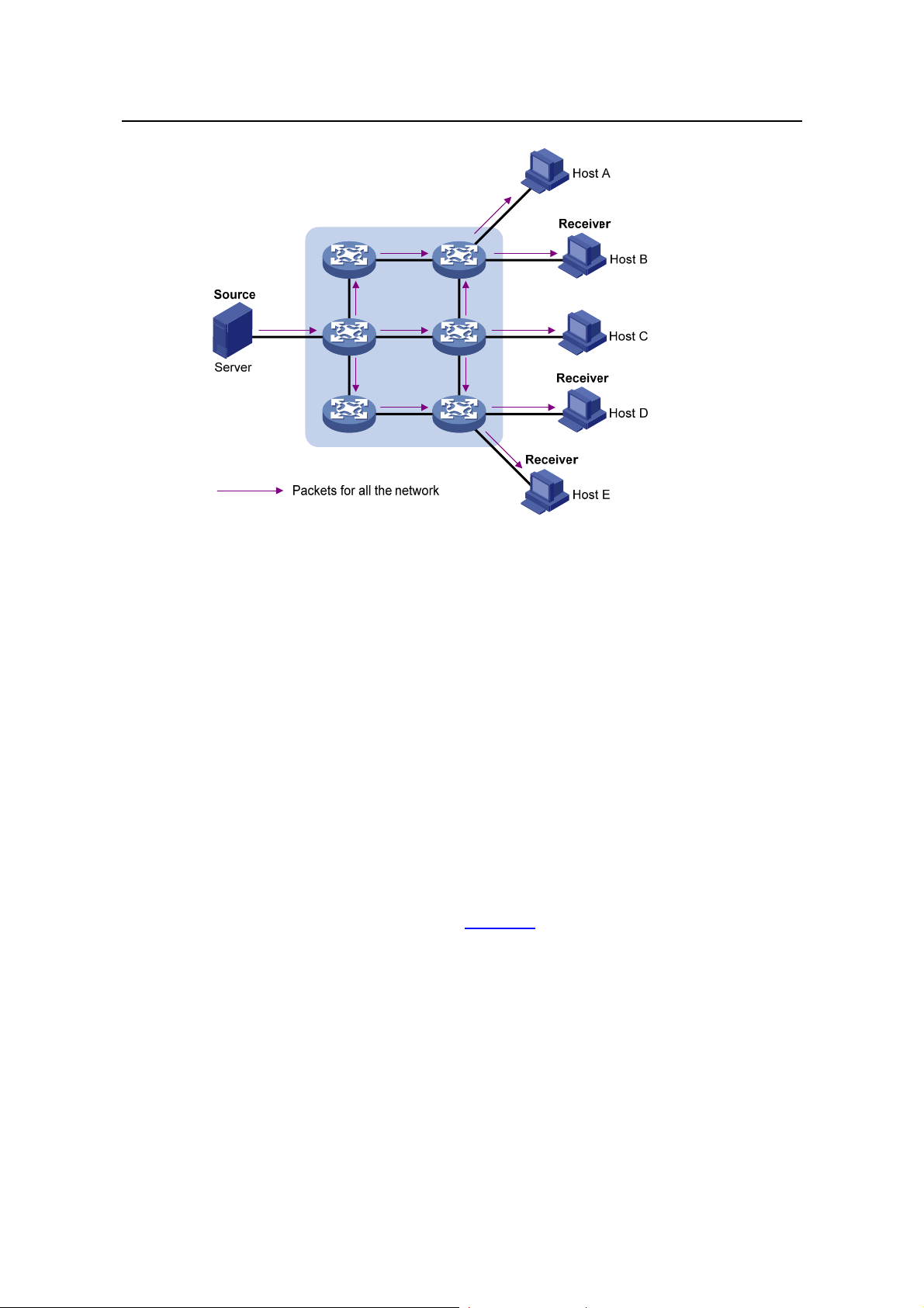
I. Unicast
In unicast, the information source sends a separate copy of information to each host
that needs the information, as shown in
Figure 1-1.
1-1
Page 8

Operation Manual – Multicast
H3C S5500-EI Series Ethernet Switches Chapter 1 Multicast Overview
Figure 1-1 Unicast transmission
Assume that Hosts B, D and E need this information. The information source
establishes a separate transmission channel for each of these hosts.
In unicast transmission, the traffic over the network is proportional to the number of
hosts that need the information. If a large number of users need the information, the
information source needs to send a copy of the same information to each of these users.
This means a tremendous pressure on the information source and the network
bandwidth.
As we can see from the information transmission process, unicast is not suitable for
batch transmission of information.
II. Broadcast
In broadcast, the information source sends information to all h osts on the network, even
if some hosts do not need the information, as shown in
Figure 1-2.
1-2
Page 9
Operation Manual – Multicast
H3C S5500-EI Series Ethernet Switches Chapter 1 Multicast Overview
Figure 1-2 Broadcast transmission
Assume that only Hosts B, D, and E need the information. If the information source
broadcasts the information, Hosts A and C also receive it. In addition to information
security issues, this also causes traffic flooding on the same network.
Therefore, broadcast is disadvantageous in transmitting data to specific hosts;
moreover, broadcast transmission is a significant usage of network resources.
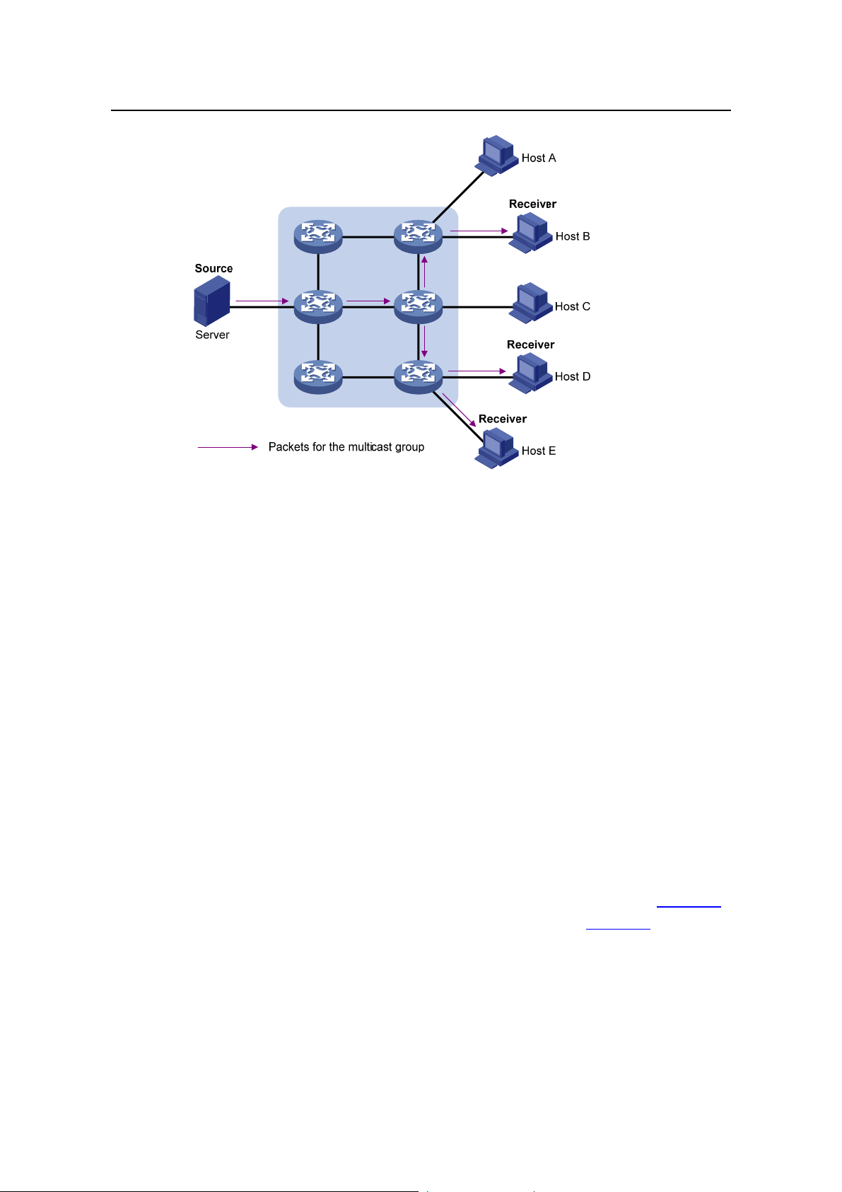
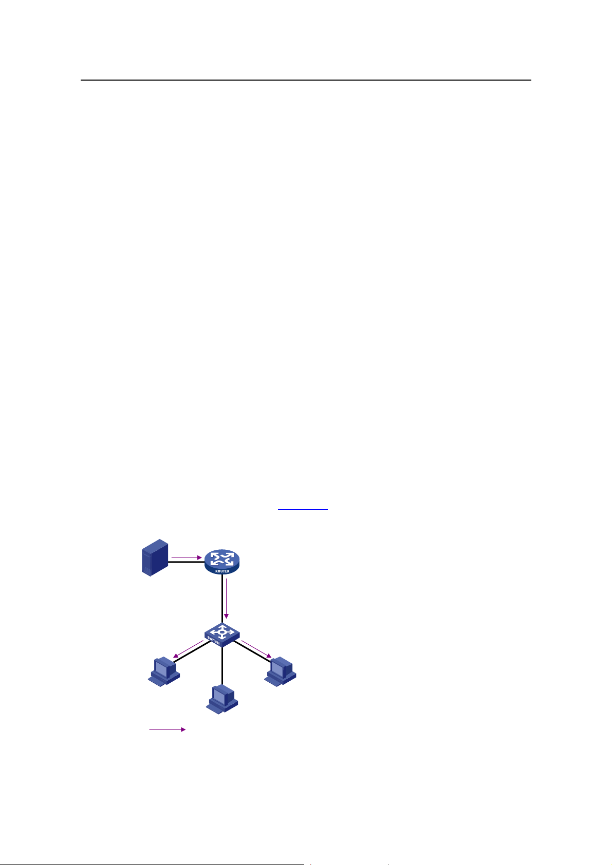
III. Multicast
As discussed above, the unicast and broadcast techniques are unable to provide
point-to-multipoint data transmissions with the minimum network consumption.
The multicast technique has solved this problem. When some hosts on the network
need multicast information, the multicast source (Source in the figure) sends only one
copy of the information. Multicast distribution threes are built for the multicast packets
through multicast routing protocols, and the packets are replicated only on nodes
where the trees branch, as shown in
Figure 1-3:
1-3
Page 10
Operation Manual – Multicast
H3C S5500-EI Series Ethernet Switches Chapter 1 Multicast Overview
Figure 1-3 Multicast transmission
Assume that Hosts B, D and E need the information. To receive the information
correctly, these hosts need to join a receiver set, which is known as a multicast group.
The routers on the network duplicate and forward the information based on the
distribution of the receivers in this set. Finally, the information is correctly delivered to
Hosts B, D, and E.
To sum up, multicast has the following advantages:
z Over unicast: As multicast traffic flows to the node the farthest possible from the
source before it is replicated and distributed, an increase of the number of hosts
will not remarkably add to the network load.
z Over broadcast: As multicast data is sent only to the receivers that need it,
multicast uses the network bandwidth reasonably and brings no waste of network
resources, and enhances network security.
1.1.2 Roles in Multicast
The following roles are involved in multicast transmission:
z An information sender is referred to as a Multicast Source (“Source” in Figure 1-3).
z Each receiver is a Multicast Group Member (“Receiver” in Figure 1-3).
z All receivers interested in the same information form a Multicast Group. Multicast
groups are not subject to geographic restrictions.
z A router that supports Layer 3 multicast is called multicast router or Layer 3
multicast device. In addition to providing the multicast routing function, a multicast
router can also manage multicast group members.
1-4
Page 11

Operation Manual – Multicast
H3C S5500-EI Series Ethernet Switches Chapter 1 Multicast Overview
For a better understanding of the multicast concept, you can assimilate multicast
transmission to the transmission of TV programs, as shown in
Table 1-1.
Table 1-1 An analogy between TV transmission and multicast transmission
Step TV transmission Multicast transmission
1
2
3
4
A TV station transmits a TV
program through a channel.
A user tunes the TV set to the
channel.
The user starts to watch the TV
program transmitted by the TV
station via the channel.
The user turns off the TV set or
tunes to another channel.
A multicast source sends multicast
data to a multicast group.
A receiver joins the multicast group.
The receiver starts to receive the
multicast data that the source sends
to the multicast group.
The receiver leaves the multicast
group or joins another group.
Note:
z A multicast source does not necessarily belong to a multicast group. Namely, a
multicast source is not necessarily a multicast data receiver.
z A multicast source can send data to multiple multicast groups at the same time, and
multiple multicast sources can send data to the same multicast group at the same
time.
1.1.3 Advantages and Applications of Multicast
I. Advantages of multicast
Advantages of the multicast technique include:
z Enhanced efficiency: reduces the CPU load of information source servers and
network devices.
z Optimal performance: reduces redundant traffic.
z Distributive application: Enables point-to-multiple-point applications at the price of
the minimum network resources.
II. Applications of multicast
Applications of the multicast technique include:
z Multimedia and streaming applications, such as Web TV, Web radio, and real-time
video/audio conferencing.
z Communication for training and cooperative operations, su ch as distance learning
and telemedicine.
z Data warehouse and financial applications (stock quotes).
1-5
Page 12

Operation Manual – Multicast
H3C S5500-EI Series Ethernet Switches Chapter 1 Multicast Overview
z Any other point-to-multiple-point data distribution application.
1.2 Multicast Models
Based on how the receivers treat the multicast sources, there are two multicast models:
I. ASM model
In the ASM model, any sender can send information to a multicast group as a multicast
source, and numbers of receivers can join a multicast group identified by a group
address and obtain multicast information addressed to that multicast group. In this
model, receivers are not aware of the position of multicast sources in advance.
However, they can join o r leave the multicast group at any time.
II. SSM model
In the practical life, users may be interested in the multicast data from only certain
multicast sources. The SSM model provides a transmission service that allows users to
specify the multicast sources they are interested in at the client side.
The radical difference between the SSM model and the ASM model is that in the SSM
model, receivers already know the locations of the multicast sources by some other
means. In addition, the SSM model uses a multicast address range that is differe nt from
that of the ASM model, and dedicated multicast forwarding paths are established
between receivers and the specified multicast sources.
1.3 Multicast Architecture
IP multicast addresses the following questions:
z Where should the multicast source transmit information to? (multicast addressing)
z What receivers exist on the network? (host registration)
z Where is the multicast source from which the receivers need to receive multicast
data? (multicast source discovery)
z How should information be transmitted to the receivers? (multicast routing)
IP multicast falls in the scope of end-to-end service. The multicast architectu re involves
the following four parts:
1) Addressing mechanism: Information is sent from a multicast source to a group of
receivers through a multicast address.
2) Host registration: Receiver hosts are allowed to join and leave multicast groups
dynamically. This mechanism is the basis for group membership management.
3) Multicast routing: A multicast distribution tree (namely a forwarding path tree for
multicast data on the network) is constructed for delivering multicast data from a
multicast source to receivers.
4) Multicast applications: A software system that supports multicast applications,
such as video conferencing, must be installed on multicast sources and receiver
1-6
Page 13

Operation Manual – Multicast
H3C S5500-EI Series Ethernet Switches Chapter 1 Multicast Overview
hosts, and the TCP/IP stack must support reception and transmission of multicast
data.
1.3.1 Multicast Addresses
To allow communication between multicast sources and multicast group members,
network-layer multicast addresses, namely, multicast IP addresses must be provided.
In addition, a technique must be available to map multicast IP addresses to link-layer
multicast MAC addresses.
I. IPv4 multicast addresses
Internet Assigned Numbers Authority (IANA) assigned the Class D address space
(224.0.0.0 to 239.255.255.255) for IPv4 multicast. The specific address blocks and
usages are shown in
Table 1-2 Class D IP address blocks and description
Address block Description
Table 1-2.
224.0.0.0 to 224.0.0.255
224.0.1.0 to 238.255.255.255
239.0.0.0 to 239.255.255.255
Reserved permanent group addresses. The IP
address 224.0.0.0 is reserved, and other IP
addresses can be used by routing protocols and for
topology searching, protocol maintenance, and so
on. Commonly used permanent group addresses
are listed in
Table 1-3. A packet destined for an
address in this block will not be forwarded beyond
the local subnet regardless of the Time to Live
(TTL) value in the IP header.
Globally scoped group addresses. This block
includes two types of designated group addresses:
z 232.0.0.0/8: SSM group addresses, and
z 233.0.0.0/8: Glop group addresses; for details,
see RFC 2770.
Administratively scoped multicast addresses.
These addresses are considered to be locally
rather than globally unique, and can be reused in
domains administered by different organizations
without causing conflicts. For details, refer to RFC
2365.
1-7
Page 14

Operation Manual – Multicast
H3C S5500-EI Series Ethernet Switches Chapter 1 Multicast Overview
Note:
z The membership of a group is dynamic. Hosts can join or leave multicast groups at
any time.
z “Glop” is a mechanism for assigning multicast addresses between different
autonomous systems (ASs). By filling an AS number into the middle two bytes of
233.0.0.0, you get 255 multicast addresses for that AS.
Table 1-3 Some reserved multicast addresses
Address Description
224.0.0.1 All systems on this subnet, including hosts and routers
224.0.0.2 All multicast routers on this subnet
224.0.0.3 Unassigned
224.0.0.4 Distance Vector Multicast Routing Protocol (DVMRP) routers
224.0.0.5 Open Shortest Path First (OSPF) routers
224.0.0.6 OSPF designated routers/backup designated routers
224.0.0.7 Shared Tree (ST) routers
224.0.0.8 ST hosts
224.0.0.9 Routing Information Protocol version 2 (RIPv2) routers
224.0.0.11 Mobile agents
224.0.0.12 Dynamic Host Configuration Protocol (DHCP) server/relay agent
224.0.0.13 All Protocol Independent Multicast (PIM) routers
224.0.0.14 Resource Reservation Protocol (RSVP) encapsulation
224.0.0.15 All Core-Based Tree (CBT) routers
224.0.0.16 Designated Subnetwork Bandwidth Management (SBM)
224.0.0.17 All SBMs
224.0.0.18 Virtual Router Redundancy Protocol (VRRP)
II. IPv6 Multicast Addresses
As defined in RFC 4291, the format of an IPv6 multicast is as follows:
1-8
Page 15

Operation Manual – Multicast
H3C S5500-EI Series Ethernet Switches Chapter 1 Multicast Overview
Figure 1-4 IPv6 multicast format
z 0xFF: 8 bits, indicating that this address is an IPv6 multicast address.
z Flags: 4 bits, of which the high-order flag is reserved and set to 0; the definition
and usage of the second bit can be found in RFC 3956; and definition and usage
of the third bit can be found in RFC 3306; the low-order bit is the Transient (T) flag.
When set to 0, the T flag indicates a permanently-assigned multicast address
assigned by IANA; when set to 1, the T flag indicates a transient, or dynamically
assigned multicast address.
z Scope: 4 bits, indicating the scope of the IPv6 internetwork for which the multicast
traffic is intended. Possible values of this field are given in
z Reserved: 80 bits, all set to 0 currently.
z Group ID: 112 bits, identifying the multicast group. For details about this field, refer
Table 1-4.
to RFC 3306.
Table 1-4 Values of the Scope field
Value Meaning
0, 3, F Reserved
1 Node-local scope
2 Link-local scope
4 Admin-local scope
5 Site-local scope
6, 7, 9 through D Unassigned
8 Organization-local scope
E Global scope
III. Ethernet multicast MAC addresses
When a unicast IP packet is transmitted over Ethernet, the destination MAC address is
the MAC address of the receiver. When a multicast p acket is transmitted over Ethernet,
however, the destination address is a multicast MAC address because the packet is
directed to a group formed by a number of receivers, rather than to one specific
receiver .
1-9
Page 16
Operation Manual – Multicast
H3C S5500-EI Series Ethernet Switches Chapter 1 Multicast Overview
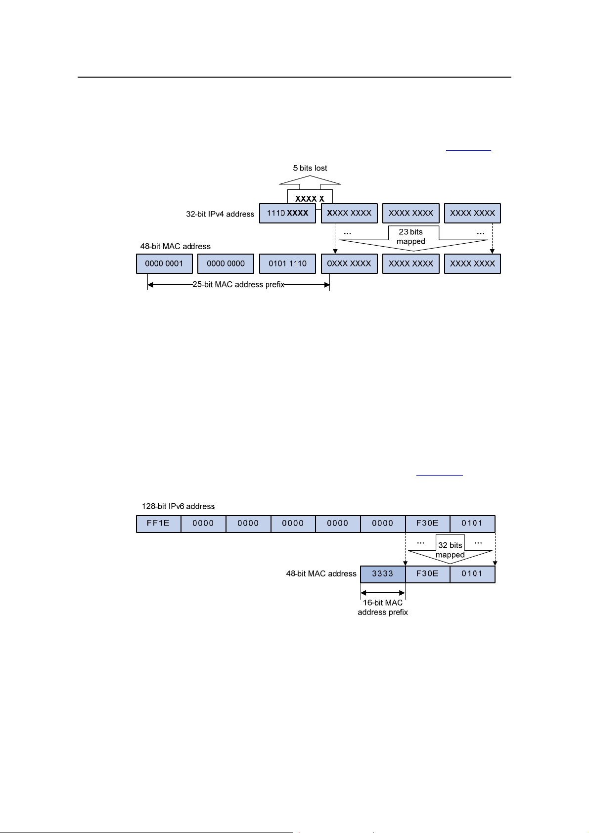
1) IPv4 multicast MAC addresses
As defined by IANA, the high-order 24 bits of an IPv4 multicast MAC address are
0x01005e, bit 25 is 0x0, and the low-order 23 bits are the low-order 23 bits of a
multicast IPv4 address. The IPv4-to-MAC mapping relation is shown in
Figure 1-5.
Figure 1-5 IPv4-to-MAC address mapping
The high-order four bits of a multicast IPv4 address are 1110, indicating that this
address is a multicast address, and only 23 bits of the remaining 2 8 bits are mapped t o
a MAC address, so five bits of the multicast IPv4 address are lost. As a result, 32
multicast IPv4 addresses map to the same MAC address. Therefore, in Layer 2
multicast forwarding, a device may receive some multicast data addressed for other
IPv4 multicast groups, and such redundant data n eeds to be filtered by the upper layer.
2) IPv6 multicast MAC addresses
The high-order 16 bits of an IPv6 multicast MAC address are 0x3333, and the low-order
32 bits are the low-order 32 bits of a multicast IPv6 address.
Figure 1-6 shows an
example of mapping an IPv6 multicast address, FF1E::F30E:0101, to a MAC address.
Figure 1-6 An example of IPv6-to-MAC address mapping
1-10
Page 17
Operation Manual – Multicast
H3C S5500-EI Series Ethernet Switches Chapter 1 Multicast Overview
1.3.2 Multicast Protocols
Note:
z Generally, we refer to IP multicast working at the network layer as Layer 3 multicast
and the corresponding multicast protocols as Layer 3 multicast protocols, which
include IGMP/MLD, PIM/IPv6 PIM, and MSDP; we refer to IP multicast working at
the data link layer as Layer 2 multicast and the corresponding multicast protocols as
Layer 2 multicast protocols, which include IGMP Snooping/MLD Snooping, and
multicast VLAN/IPv6 multicast VLAN.
z IGMP Snooping, IGMP, multicast VLAN, PIM and MSDP are for IPv4, MLD
Snooping, MLD, IPv6 multicast VLAN, and IPv6 PIM are for IPv6.
This section provides only general descriptions about appli cations and function s of the
Layer 2 and Layer 3 multicast protocols in a network. For details of these protocols,
refer to the respective chapters.
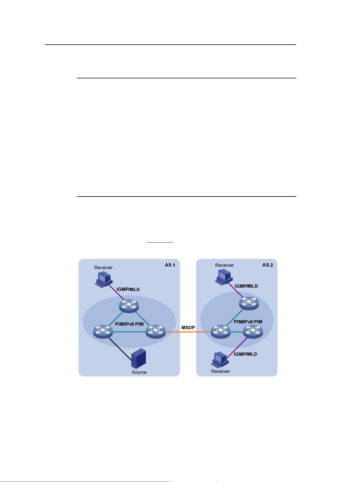
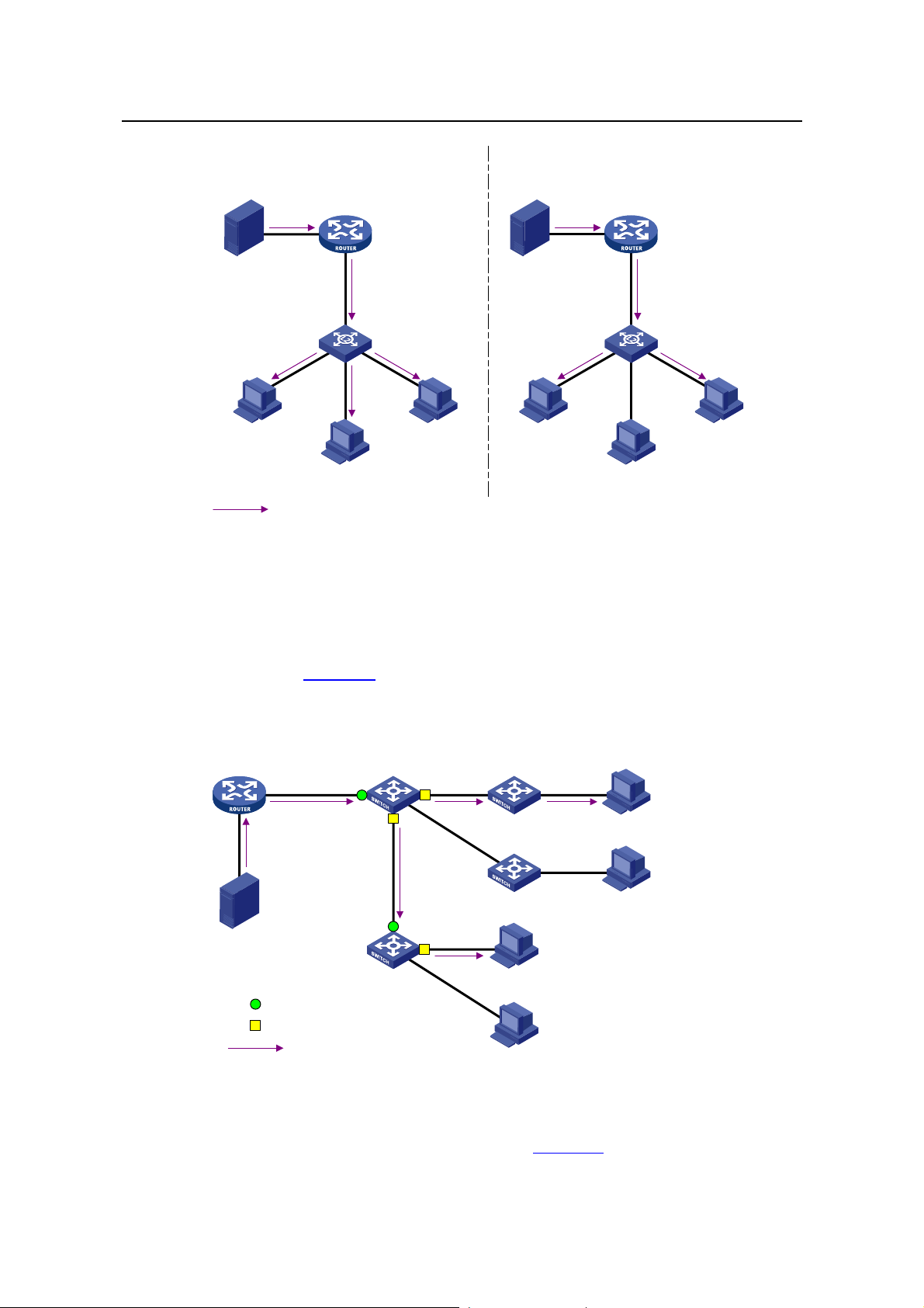
I. Layer 3 multicast protocols
Layer 3 multicast protocols include multicast group management protocols and
multicast routing protocols.
Figure 1-7 describes where these multicast protocols are in
a network.
Figure 1-7 Positions of Layer 3 multicast protocols
1) Multicast management protocols
Typically, the internet group management protocol (IGMP) or multicast listener
discovery protocol (MLD) is used between host s and Layer 3 multicast devices di rectly
1-11
Page 18
Operation Manual – Multicast
H3C S5500-EI Series Ethernet Switches Chapter 1 Multicast Overview
connected with the hosts. These protocols define the mechanism of establishing and
maintaining group memberships between hosts and Layer 3 multicast devices.
2) Multicast routing protocols
A multicast routing proto col runs on Layer 3 multicast devices to esta blish and maintain
multicast routes and forward multicast packets correctly and ef ficiently . Multicast routes
constitute a loop-free data transmission path from a data source to multiple receivers,
namely, a multicast distribution tree.
In the ASM model, multicast routes come in intra-domain routes and inter-domain
routes.
z An intra-domain multicast routing protocol is used to discover multicast sources
and build multicast distribution trees within an AS so as to deliver multicast data to
receivers. Among a variety of mature intra-domain multicast routing protocols,
protocol independent multicast (PIM) is a popular one. Based on the forwarding
mechanism, PIM comes in two modes – dense mode (often referred to as PIM-DM)
and sparse mode (often referred to as PIM-SM).
z An inter-domain multicast routing protocol is used for delivery of multicast
information between two ASs. So far, mature solutions include multicast source
discovery protocol (MSDP).
For the SSM model, multicast routes are not divided into inter-domain routes and
intra-domain routes. Since receivers know the position of the multicast source,
channels established through PIM-SM are suff icient for multicast information transport.
II. Layer 2 multicast protocols
Layer 2 multicast protocols include IGMP Snooping/MLD Snooping and multicast
VLAN/IPv6 multicast VLAN.
Figure 1-8 shows where these protocols are in the
network.
Source
Receiver Receiver
Multicast VLAN
/IPv6 Multicast VLAN
IGMP Snooping
/MLD Snooping
IPv4/IPv6 multicast packets
Figure 1-8 Position of Layer 2 multicast protocols
1-12
Page 19

Operation Manual – Multicast
H3C S5500-EI Series Ethernet Switches Chapter 1 Multicast Overview
1) IGMP Snooping/MLD Snooping
Running on Layer 2 devices, Internet Group Management Protocol Snooping (IGMP
Snooping) and Multicast Listener Discovery Snooping (MLD Snooping) are multicast
constraining mechanisms that manage and control multicast groups by listening to and
analyzing IGMP or MLD messages exchanged between the hosts and Layer 3
multicast devices, thus effectively controlling the flooding of multicast dat a i n a L ayer 2
network.
2) Multicast VLAN/IPv6 multicast VLAN
In the traditional multicast-on-demand mode, when users in differen t VLANs on a Layer
2 device need multicast information, the upstream Layer 3 device needs to forward a
separate copy of the multicast data to each VLAN of the Layer 2 device. With the
multicast VLAN or IPv6 multicast VLAN feature enabled on the Layer 2 device, the
Layer 3 multicast device needs to send only one copy of multicast to the multicast
VLAN or IPv6 multicast VLAN on the Layer 2 device. This avoids waste of network
bandwidth and extra burden on the Layer 3 device.
1.4 Multicast Packet Forwarding Mechanism
In a multicast model, a multicast source sends information to the host group identified
by the multicast group address in the destination address field of IP multicast packets.
Therefore, to deliver multicast packets to receivers located in different parts of the
network, multicast routers on the forwarding path usually need to forward multicast
packets received on one incoming interface to multiple outgoing interfaces. Compared
with a unicast model, a multicast model is more complex in the following aspect s.
z To ensure multicast packet transmission in the network, unicast routing tables or
multicast routing tables specially provided for multicast must be used as guidance
for multicast forwarding.
z To process the same multicast information from different peers received on
different interfaces of the same device, every multicast packet is subject to a
reverse path forwarding (RPF) check on the incoming interface. The result of the
RPF check determines whether the packet will be forwarded or discarded. The
RPF check mechanism is the basis for most multicast routing protocols to
implement multicast forwarding.
Note:
For details about the RPF mechanism, refer to RPF Mechanism.
1-13
Page 20

Operation Manual – Multicast
H3C S5500-EI Series Ethernet Switches Chapter 2 IGMP Snooping Configuration
Chapter 2 IGMP Snooping Configuration
When configuring IGMP Snooping, go to the following sections for information you are
interested in:
z IGMP Snooping Overview
z IGMP Snooping Configuration Task List
z Displaying and Maintaining IGMP Snooping
z IGMP Snooping Configuration Examples
z Troubleshooting IGMP Snooping Configuration
2.1 IGMP Snooping Overview
Internet Group Management Protocol Snooping (IGMP Snooping) is a multicast
constraining mechanism that runs on Layer 2 devices to manage and control multicast
groups.
2.1.1 Principle of IGMP Snooping
By analyzing received IGMP messages, a Layer 2 device running IGMP Snooping
establishes mappings between ports and multicast IP addresses and forwards
multicast data based on these mappings.
As shown in
packets are broadcast to all devices at Layer 2. When IGMP Snooping is running on the
switch, multicast packets for known multicast groups are multicast to the receivers,
rather than broadcast to all hosts, at Layer 2.
Figure 2-1, when IGMP Snooping is not running on the switch, multicast
2-1
Page 21
Operation Manual – Multicast
H3C S5500-EI Series Ethernet Switches Chapter 2 IGMP Snooping Configuration
Multicast packet transmission
without IGMP Snooping
Multicast router
Source
Layer 2 switch
Host A
Receiver
Host B
Multicast packets
Host C
Receiver
Figure 2-1 Before and after IGMP Snooping is enabled on the Layer 2 device
2.1.2 Basic Concepts in IGMP Snooping
Multicast packet transmission
when IGMP Snooping runs
Source
Host A
Receiver
Host B
Multicast router
Layer 2 switch
Host C
Receiver
I. IGMP Snooping related ports
As shown in Figure 2-2, Router A connects to the multicast source, IGMP Snooping
runs on Switch A and Switch B, Host A and Ho st C are receiver hosts (namely, multicast
group members).
Router A Switch A
Eth1/0/1 Eth1/0/2
Eth1/0/3
Eth1/0/1
Source
Switch B
Router port
Member port
Multicast packets
Receiver
Eth1/0/2
Host C
Host D
Receiver
Host A
Host B
Figure 2-2 IGMP Snooping related ports
Ports involved in IGMP Snooping, as shown in
2-2
Figure 2-2, are described as follows:
Page 22

Operation Manual – Multicast
H3C S5500-EI Series Ethernet Switches Chapter 2 IGMP Snooping Configuration
z Router port: A router port is a port on the Ethernet switch that leads switch towards
the Layer 3 multicast device (DR or IGMP querier). In the figure, Ethernet 1/0/1 of
Switch A and Ethernet 1/0/1 of Switch B are router ports. The switch registers all
its local router ports (including static and dynamic router ports) in its router port list .
z Member port: A member port is a port on the Ethernet switch that leads switch
towards multicast group members. In the figure, Ethernet 1/0/2 and Ethernet 1/0/3
of Switch A and Ethernet 1/0/2 of Switch B are member ports. The swit ch registers
all the member ports (including static and dynamic member ports) on the local
device in its IGMP Snooping forwarding table.
Note:
z Whenever mentioned in this document, a router port is a port on the switch that
leads the switch to a Layer 3 multicast device, rather than a port on a router.
z An IGMP-snooping-enabled switch deems that all its ports on which IGMP general
queries with the source address other than 0.0.0.0 or PIM hello messages are
received to be router ports.
II. Aging timers for dynamic ports in IGMP Snooping and related messages
and actions
Table 2-1 Aging timers for dynamic ports in IGMP Snooping and related messages and
actions
Timer Description
For each router
port, the switch
Router port aging
timer
sets a timer
initialized to the
aging time of the
route port.
Message before
expiry
IGMP general
query of which the
source address is
not 0.0.0.0 or PIM
hello
Action after
expiry
The switch
removes this port
from its router port
list.
When a port joins
Member port aging
timer
a multicast group,
the switch sets a
timer for the port,
which is initialized
to the member port
aging time.
IGMP membership
report
The switch
removes this port
from the multicast
group forwarding
table.
2-3
Page 23

Operation Manual – Multicast
H3C S5500-EI Series Ethernet Switches Chapter 2 IGMP Snooping Configuration
Note:
The port aging mechanism of IGMP Snooping works only for dynamic ports; a static
port will never age out.
2.1.3 Work Mechanism of IGMP Snooping
A switch running IGMP Snooping performs different actions when it receives different
IGMP messages, as follows:
I. When receiving a general query
The IGMP querier periodically sends IGMP general queries to all hosts and routers
(224.0.0.1) on the local subnet to find out whether active multicast group members
exist on the subnet.
Upon receiving an IGMP general query, the switch forwards it through all ports in the
VLAN except the receiving port and performs the following to the receiving port:
z If the receiving port is a router port existing in its router port list, the switch resets
the aging timer of this router port.
z If the receiving port is not a router port existing in its router port list, the switch adds
it into its router port list and sets an aging timer for this router port.
II. When receiving a membership report
A host sends an IGMP report to the multicast router in the following circumstances:
z Upon receiving an IGMP query, a multicast group member host responds with an
IGMP report.
z When intended to join a multicast group, a host sends an IGMP report to the
multicast router to announce that it is interested in the multicast information
addressed to that group.
Upon receiving an IGMP report, the switch forwards it through all the router po rts in the
VLAN, resolves the address of the reported multicast group, and performs the
following:
z If no forwarding table entry exists for the reported group, the switch creates an
entry, adds the port as member port to the outgoing port list, and starts a member
port aging timer for that port.
z If a forwarding table entry exists for the reported group, but the port is not included
in the outgoing port list for that group, the switch adds the port as a member port to
the outgoing port list, and starts a member port aging timer for that port.
2-4
Page 24

Operation Manual – Multicast
H3C S5500-EI Series Ethernet Switches Chapter 2 IGMP Snooping Configuration
z If a forwarding table entry exists for the reported group and the port is included in
the outgoing port list, which means that this port is already a member port, the
switch resets the member port aging timer for that port.
Note:
A switch does not forward an IGMP report through a non-router port. The reason is as
follows: Due to the IGMP report suppression mechanism, if the switch forwards a report
message through a member port, all the attached hosts listening to the reported
multicast address will suppress their own reports upon hea ring thi s repo rt, and this will
prevent the switch from knowing whether any hosts attached to that port are still active
members of the reported multicast group.
For the description of IGMP report suppression mechanism, refer to
of IGMPv1
.
Work Mechanism
III. When receiving a leave group message
When an IGMPv1 host leaves a multicast group, the host does not send an IGMP leave
group message, so the switch cannot know immediately that the host has left the
multicast group. However , as the ho st stop s sending IGMP report s as soo n as it leaves
a multicast group, the switch deletes the forwarding entry for the member port
corresponding to the host from the forwarding table when its aging timer expires.
When an IGMPv2 or IGMPv3 host leaves a multicast group, the host sends an IGMP
leave group message to the multicast router.
When the switch hears a group-specific IGMP leave g roup message on a member port,
it first checks whether a forwarding table entry for that group exists, and, if one exists,
whether its outgoing port list contains that port.
z If the forwarding table entry does not exist or if its outgoing port list does not
contain the port, the switch discards the IGMP leave group message instead of
forwarding it to any port.
z If the forwarding table entry exists and its outgoing port list contains the port, the
switch forwards the leave group message to all router ports in the VLAN. Because
the switch does not know whether any other hosts attached to the port are still
listening to that group address, the switch does not immediately removes the port
from the outgoing port list of the forwarding table entry for that group; instead, it
resets the member port aging timer for the port.
Upon receiving the IGMP leave group message from a host, the IGMP querier resolves
from the message the address of the multicast group that the host just left and sends an
IGMP group-specific query to that multicast group through the port that received the
leave group message. Upon hearing the IGMP group-specific query, the switch
2-5
Page 25

Operation Manual – Multicast
H3C S5500-EI Series Ethernet Switches Chapter 2 IGMP Snooping Configuration
forwards it through all its router ports in the VLAN and all member ports for that
multicast group, and performs the following:
z If any IGMP report in response to the group-specific query is heard on a member
port before its aging timer expires, this means that some host attached to the port
is receiving or expecting to receive multicast data for that multicast group. The
switch resets the aging timer of the member port.
z If no IGMP report in response to the group-specific query is heard on a member
port before its aging timer expires, this means that no hosts attached to the port
are still listening to that group address: the switch removes the port from the
outgoing port list of the forwarding table entry for that multicast group when the
aging timer expires.
2.1.4 Processing of Multicast Protocol Messages
With Layer 3 multicast routing enabled, an IGMP Snooping switch processes multicast
protocol messages differently under different conditions, specifically as follows:
1) If only IGMP is enabled, or both IGMP and PIM are enabled on the switch, the
switch handles multicast protocol messages in the normal way.
2) In only PIM is enabled on the switch:
z The switch broadcasts IGMP messages as unknown messages in the VLAN.
z Upon receiving a PIM hello message, the switch will maintain the corresponding
router port.
3) When IGMP is disabled on the switch, or when IGMP forwarding entries are
cleared (by using the reset igmp group command):
z If PIM is disabled, the switch clears all its Layer 2 multicast entries and router
ports.
z If PIM is enabled, the switch clears only its Layer 2 multicast entries without
deleting its router ports.
4) When PIM is disabled on the switch:
z If IGMP is disabled, the switch clears all its router ports.
z If IGMP is enabled, the switch maintains all its Layer 2 multicast entries and router
ports.
2.1.5 Protocols and Standards
IGMP Snooping is documented in:
z RFC 4541: Considerations for Internet Group Management Protocol (IGMP) and
Multicast Listener Discovery (MLD) Snooping Switches
2-6
Page 26

Operation Manual – Multicast
H3C S5500-EI Series Ethernet Switches Chapter 2 IGMP Snooping Configuration
2.2 IGMP Snooping Configuration Task List
Complete these tasks to configure IGMP Snooping:
Task Remarks
Configuring Basic
Functions of IGMP
Snooping
Configuring IGMP
Snooping Port
Functions
Configuring IGMP
Snooping Querier
Configuring an
IGMP Snooping
Policy
Enabling IGMP Snooping Required
Configuring the Version of IGMP
Snooping
Configuring Aging Timers for Dynamic
Ports
Configuring Static Ports Optional
Configuring Simulated Joining Optional
Configuring Fast Leave Processing Optional
Enabling IGMP Snooping Querier Optional
Configuring IGMP Queries and
Responses
Configuring Source IP Address of IGMP
Queries
Configuring a Multicast Group Filter Optional
Configuring Multicast Source Port
Filtering
Configuring the Function of Dropping
Unknown Multicast Data
Configuring IGMP Report Suppression Optional
Optional
Optional
Optional
Optional
Optional
Optional
Configuring Maximum Multicast Groups
that Can Be Joined on a Port
Configuring Multicast Group
Replacement
2-7
Optional
Optional
Page 27

Operation Manual – Multicast
H3C S5500-EI Series Ethernet Switches Chapter 2 IGMP Snooping Configuration
Note:
z Configurations made in IGMP Snooping view are effective for all VLANs, while
configurations made in VLAN view are effective only for ports belonging to the
current VLAN. For a given VLAN, a configuration made in IGMP Snooping view is
effective only if the same configuration is not made in VLAN view.
z Configurations made in IGMP Snooping view are effective for all ports;
configurations made in Ethernet port view are effective only for the current port;
configurations made in manual port group view are effective only for all the ports in
the current port group; configurations made in aggregation group view are effective
only for the master port. For a given port, a configuration made in IGMP Snooping
view is effective only if the same configuration is not made in Ethernet port view or
port group view.
2.3 Configuring Basic Functions of IGMP Snooping
2.3.1 Configuration Prerequisites
Before configuring the basic functions of IGMP Snooping, complete the following task:
z Configure the corresponding VLANs.
Before configuring the basic functions of IGMP Snooping, prepare the following data:
z Version of IGMP Snooping.
2.3.2 Enabling IGMP Snooping
Follow these steps to enable IGMP Snooping:
To do... Use the command... Remarks
Enter system view
Enable IGMP Snooping
globally and enter
IGMP-Snooping view
Return to system view
Enter VLAN view
Enable IGMP Snooping in
the VLAN
system-view
vlan vlan-id
igmp-snooping
quit
igmp-snooping enable
—
Required
Disabled by default
—
—
Required
Disabled by default
2-8
Page 28

Operation Manual – Multicast
H3C S5500-EI Series Ethernet Switches Chapter 2 IGMP Snooping Configuration
Note:
z IGMP Snooping must be enabled globally before it can be enabled in a VLAN.
z After enabling IGMP Snooping in a VLAN, you cannot enable IGMP and/or PIM on
the corresponding VLAN interface, and vice versa.
z When you enable IGMP Snooping in a specified VLAN, this function takes effect for
Ethernet ports in this VLAN only.
2.3.3 Configuring the Version of IGMP Snooping
By configuring an IGMP Snooping version, you actually configure the version of IGMP
messages that IGMP Snooping can process.
z IGMP Snooping version 2 can process IGMPv1 and IGMPv2 messages, but not
IGMPv3 messages, which will be flooded in the VLAN.
z IGMP Snooping version 3 can process IGMPv1, IGMPv2 and IGMPv3 messages.
Follow these steps to configure the version of IGMP Snooping:
To do... Use the command... Remarks
Enter system view
Enter VLAN view
system-view
vlan vlan-id
Configure the version of
IGMP Snooping
igmp-snooping version
version-number
—
—
Optional
Version 2 by default
Caution:
If you switch IGMP Snooping from version 3 to version 2, the system will clear all IGMP
Snooping forwarding entries from dynamic joins, and will:
z Keep forwarding entries for version 3 static (*, G) joins;
z Clear forwarding entries from version 3 static (S, G) joins, which will be restored
when IGMP Snooping is switched back to version 3.
For details about static joins, Refer to
Configuring Static Ports.
2.4 Configuring IGMP Snooping Port Functions
2.4.1 Configuration Prerequisites
Before configuring IGMP Snooping port functions, complete the following t asks:
2-9
Page 29

Operation Manual – Multicast
H3C S5500-EI Series Ethernet Switches Chapter 2 IGMP Snooping Configuration
z Enable IGMP Snooping in the VLAN or enable IGMP on the desired VLAN
interface
z Configure the corresponding port groups.
Before configuring IGMP Snooping port functions, prepare the following data:
z Aging time of router ports,
z Aging timer of member ports, and
z Multicast group and multicast source addresses
2.4.2 Configuring Aging Timers for Dynamic Ports
If the switch receives no IGMP general queries or PIM hello messages on a dynamic
router port, the switch removes the port from the router port list when the aging timer of
the port expires.
If the switch receives no IGMP reports for a multi cast group on a dynamic member port,
the switch removes the port from the outgoing port list of the forwarding table entry for
that multicast group when the aging timer of the port for that group expires.
If multicast group memberships change frequently, you can set a relatively small value
for the member port aging timer , and vice versa.
I. Configuring aging timers for dynamic ports globally
Follow these steps to configure aging timers for dynamic ports globally:
To do... Use the command... Remarks
Enter system view
system-view
Enter IGMP Snooping
view
Configure router port
aging time
Configure member port
aging time
igmp-snooping
router-aging-time
interval
host-aging-time interval
—
—
Optional
105 seconds by default
Optional
260 seconds by default
II. Configuring aging timers for dynamic ports in a VLAN
Follow these steps to configure aging timers for dynamic ports in a VLAN:
To do... Use the command... Remarks
Enter system view
Enter VLAN view
system-view
vlan vlan-id
Configure router port
aging time
igmp-snooping
router-aging-time
interval
2-10
—
—
Optional
105 seconds by default
Page 30

Operation Manual – Multicast
H3C S5500-EI Series Ethernet Switches Chapter 2 IGMP Snooping Configuration
To do... Use the command... Remarks
Configure member port
aging time
2.4.3 Configuring Static Ports
If all the hosts attached to a port are interested in the multicast data addressed to a
particular multicast group or the multicast data that a particular multica st source sends
to a particular group, you can configure static (*, G) or (S, G) joining on that port,
namely configure the port as a group-specific or source-and-group-specific static
member port.
You can configure a port of a switch to be a st atic rout er p ort, thro ugh which the swit ch
can forward all the multicast traffic it received.
Follow these steps to configure static ports:
To do... Use the command... Remarks
Enter system view
Enter the
corresponding
view
system-view
Enter Ethernet
port view
Enter port
group view
igmp-snooping
host-aging-time interval
interface interface-type
interface-number
port-group { manual
port-group-name |
aggregation agg-id }
Optional
260 seconds by default
—
Use either
command.
igmp-snooping
Configure the port(s) as static
member port(s)
Configure the port(s) as static
router port(s)
static-group group-address
[ source-ip
source_address ] vlan
vlan-id
igmp-snooping
static-router-port vlan
vlan-id
Required
Disabled by
default
Required
Disabled by
default
Note:
z The static (S, G) joining function is available only if a valid multicast source address
is specified and IGMP Snooping version 3 is currently running on th e switch.
z A static member port does not respond to queries from the IGMP querier; when
static (*, G) or (S, G) joining is enabled or disabled on a port, the port does not send
an unsolicited IGMP report or an IGMP leave group message.
z Static member ports and static router ports never age out. To remove such a port,
you need to use the corresponding command.
2-11
Page 31

Operation Manual – Multicast
H3C S5500-EI Series Ethernet Switches Chapter 2 IGMP Snooping Configuration
2.4.4 Configuring Simulated Joining
Generally, a host running IGMP responds to IGMP queries from the IGMP querier. If a
host fails to respond due to some reasons, the multicast router may deem that no
member of this multicast group exists on the network segment, and therefore will
remove the corresponding forwarding path.
To avoid this situation from happening, you can enable simulated joining on a port of
the switch, namely configure the port as a simulated member host for a multicast group.
When an IGMP query is heard, the simulated host gives a response. Thus, the switch
can continue receiving multicast data.
A simulated host acts like a real host, as follows:
z When a port is configured as a simulated member host, the switch sends an
unsolicited IGMP report through that port.
z After a port is configured as a simulated member host, the switch responds to
IGMP general queries by sending IGMP reports through that port.
z When the simulated joining function is disabled on a port, the switch sends an
IGMP leave group message through that port.
Follow these steps to configure simulated joining:
To do... Use the command... Remarks
Enter system view
system-view
Enter Ethernet
Enter the
port view
corresponding
view
Enter port
group view
Configure simulated (*, G) or (S,
G) joining
interface interface-type
interface-number
port-group { manual
port-group-name |
aggregation agg-id }
igmp-snooping host-join
group-address [ source-ip
source-address ] vlan vlan-id
—
Use either
command
Required
Disabled by
default
Note:
z Each simulated host is equivalent to an independent host. For example, when
receiving an IGMP query, the simulated host corresponding to each configuration
responds respectively.
z Unlike a static member port, a port configured as a simulated member host will age
out like a dynamic member port.
2-12
Page 32

Operation Manual – Multicast
H3C S5500-EI Series Ethernet Switches Chapter 2 IGMP Snooping Configuration
2.4.5 Configuring Fast Leave Processing
The fast leave processing feature allows the switch to process IGMP leave group
messages in a fast way . With the fast leave processing feature enabled, when receiving
an IGMP leave group message on a port, the switch immediately removes that port
from the outgoing port list of the forwarding table entry for the indicated group. Then,
when receiving IGMP group-specific queries for that multicast group, the switch will not
forward them to that port.
In VLANs where only one host is attached to each port, fast leave processing helps
improve bandwidth and resource usage.
I. Configuring fast leave processing globally
Follow these steps to configure fast leave processing globally:
To do... Use the command... Remarks
Enter system view
system-view
Enter IGMP Snooping
view
Enable fast leave
processing
igmp-snooping
fast-leave [ vlan vlan-list ]
—
—
Required
Disabled by default
II. Configuring fast leave processing on a port or a group of ports
Follow these steps to configure fast leave processing on a port or a group of ports:
To do... Use the command... Remarks
Enter system view
system-view
Enter Ethernet
Enter the
port view
corresponding
view
Enter port
group view
Enable fast leave processing
interface interface-type
interface-number
port-group { manual
port-group-name |
aggregation agg-id }
igmp-snooping
fast-leave [ vlan vlan-list ]
—
Use either
command
Required
Disabled by
default
2-13
Page 33

Operation Manual – Multicast
H3C S5500-EI Series Ethernet Switches Chapter 2 IGMP Snooping Configuration
Caution:
If fast leave processing is enabled on a port to which more than one host is attached,
when one host leaves a multicast group, the other hosts attached to the port and
interested in the same multicast group will fail to receive multicast data for that group.
2.5 Configuring IGMP Snooping Querier
2.5.1 Configuration Prerequisites
Before configuring IGMP Snooping querier, complete the following task:
z Enable IGMP Snooping in the VLAN.
Before configuring IGMP Snooping querier, prepare the following data:
z IGMP general query interval,
z IGMP last-member query interval,
z Maximum response time to IGMP general queries,
z Source address of IGMP general queries, and
z Source address of IGMP group-specific queries.
2.5.2 Enabling IGMP Snooping Querier
In an IP multicast network running IGMP, a multicast router or Layer 3 multicast switch
is responsible for sending IGMP general queries, so that all Layer 3 multicast devices
can establish and maintain multicast forwarding entries, thus to forward multicast traf fic
correctly at the network layer. This router or Layer 3 switch is called IGMP querier.
However, a Layer 2 multicast switch does not support IGMP, and therefore cannot send
general queries by default. By enabling IGMP Snooping on a Layer 2 swit ch in a VLAN
where multicast traffic needs to be Layer-2 switched only and no multicast routers are
present, the Layer 2 switch will act as the IGMP Snooping querier to send IGMP
queries, thus allowing multicast forwarding entries to be established and maint ai ned at
the data link layer.
Follow these steps to enable IGMP Snooping querier:
To do... Use the command... Remarks
Enter system view
Enter VLAN view
Enable IGMP Snooping
querier
system-view
vlan vlan-id
igmp-snooping querier
—
—
Required
Disabled by default
2-14
Page 34

Operation Manual – Multicast
H3C S5500-EI Series Ethernet Switches Chapter 2 IGMP Snooping Configuration
Caution:
It is meaningless to configure an IGMP Snooping querier in a multi cast network running
IGMP. Although an IGMP Snooping querier does not take part in IGMP querier
elections, it may affect IGMP querier elections because it sends IGMP general queries
with a low source IP address.
2.5.3 Configuring IGMP Queries and Responses
Y ou can tune the IGMP general query interval based on actual condition of the network.
Upon receiving an IGMP query (general query or group-specific query), a host starts a
timer for each multicast group it has joined. This timer is initialized to a random value in
the range of 0 to the maximum response time (the host obtains the value of the
maximum response time from the Max Response Time field in the IGMP query it
received). When the timer value comes down to 0, the host sends an IGMP report to the
corresponding multicast group.
An appropriate setting of the maximum response time for IGMP queries allows host s to
respond to queries quickly and avoids bursts of IGMP traffic on the network caused by
reports simultaneously sent by a large numbe r of host s when the corre sponding timers
expire simultaneously.
z For IGMP general queries, you can configure the maximum response time to fill
their Max Response time field.
z For IGMP group-specific queries, you can configure the IGMP last-member query
interval to fill their Max Response time field. Namely, for IGMP group-specific
queries, the maximum response time equals to the IGMP last-member query
interval.
I. Configuring IGMP queries and responses globally
Follow these steps to configure IGMP queries and responses globally:
To do... Use the command... Remarks
Enter system view
system-view
Enter IGMP Snooping view
Configure the maximum
response time to IGMP
general queries
igmp-snooping
max-response-time
interval
—
—
Optional
10 seconds by default
Configure the IGMP
last-member query interval
last-member-query-int
erval interval
2-15
Optional
1 second by default
Page 35

Operation Manual – Multicast
H3C S5500-EI Series Ethernet Switches Chapter 2 IGMP Snooping Configuration
II. Configuring IGMP queries and responses in a VLAN
Follow these steps to configure IGMP queries and responses in a VLAN:
To do... Use the command... Remarks
Enter system view
Enter VLAN view
system-view
vlan vlan-id
Configure IGMP general
query interval
Configure the maximum
response time to IGMP
general queries
Configure the IGMP
last-member query
interval
igmp-snooping
query-interval interval
igmp-snooping
max-response-time
interval
igmp-snooping
last-member-query-inter
val interval
—
—
Optional
60 seconds by default
Optional
10 seconds by default
Optional
1 second by default
Caution:
In the configuration, make sure that the IGMP general query interval is larger than the
maximum response time for IGMP general queries. Otherwise, multicast group
members may be deleted by mistake.
2.5.4 Configuring Source IP Address of IGMP Queries
Upon receiving an IGMP query whose source IP address is 0.0.0.0 on a port, the switch
will not set that port as a router port. This may prevent multicast forwarding entries from
being correctly created at the data link layer and cause multicast traffic forwarding
failure in the end. When a Layer 2 device acts as an IGMP-Snooping querier, to avoid
the aforesaid problem, you are commended to configure a non-all-zero IP address as
the source IP address of IGMP queries.
Follow these steps to configure source IP addre ss of IGMP queries:
To do... Use the command... Remarks
Enter system view
Enter VLAN view
Configure the source
address of IGMP general
queries
system-view
vlan vlan-id
igmp-snooping
general-query source-ip
{ current-interface |
ip-address }
—
—
Optional
0.0.0.0 by default
2-16
Page 36

Operation Manual – Multicast
H3C S5500-EI Series Ethernet Switches Chapter 2 IGMP Snooping Configuration
To do... Use the command... Remarks
Configure the source IP
address of IGMP
group-specific queries
igmp-snooping
special-query source-ip
{ current-interface |
ip-address }
Caution:
The source address of IGMP query messages may affect IGMP querier selection within
the segment.
2.6 Configuring an IGMP Snooping Policy
2.6.1 Configuration Prerequisites
Before configuring an IGMP Snooping policy, complete the following task:
z Enable IGMP Snooping in the VLAN or enable IGMP on the desired VLAN
interface
Optional
0.0.0.0 by default
Before configuring an IGMP Snooping policy, prepare the following data:
z ACL rule for multicast group filtering
z The maximum number of multicast groups that can pass the ports
2.6.2 Configuring a Multicast Group Filter
On an IGMP Snooping–enabled switch, the configuration of a multicast group allows
the service provider to define restrictions on multicast programs available to different
users.
In an actual application, when a user requests a multicast program, the user’s host
initiates an IGMP report. Upon receiving this report message, the switch checks the
report against the configured ACL rule. If the port on which the report was heard can
join this multicast group, the switch adds an entry for this port in the IGMP Snooping
forwarding table; otherwise the switch drops this report message. Any multicast data
that has failed the ACL check will not be sent to this port. In this way, the service
provider can control the VOD programs provided for multicast users.
2-17
Page 37

Operation Manual – Multicast
H3C S5500-EI Series Ethernet Switches Chapter 2 IGMP Snooping Configuration
I. Configuring a multicast group filter globally
Follow these steps to configure a multicast group filter globally:
To do... Use the command... Remarks
Enter system view
system-view
Enter IGMP Snooping
view
igmp-snooping
—
—
Required
Configure a multicast
group filter
group-policy acl-number
[ vlan vlan-list ]
No group filter is
configured by default,
namely hosts can join any
multicast group.
II. Configuring a multicast group filter on a port or a group of ports
Follow these steps to configuring a multicast group filter on a port or a group of ports:
To do... Use the command... Remarks
Enter system view
Enter the
correspondin
g view
system-view
Enter Ethernet
port view
Enter port
group view
interface interface-type
interface-number
port-group { manual
port-group-name |
aggregation agg-id }
—
Use either
command
Configure a multicast group
filter
igmp-snooping
group-policy acl-number
[ vlan vlan-list ]
2.6.3 Configuring Multicast Source Port Filtering
With the multicast source port filtering feature enabled on a port, the port can be
connected with multicast receivers only rather than with multicast sources, because the
port will block all multicast data packets while it permits multicast protocol packets to
pass.
If this feature is disabled on a port, the port can be connected with both multicast
sources and multicast receivers.
I. Configuring multicast source port filtering globally
Follow these steps to configure multicast source port filtering globally:
Required
No filter is
configured by
default, namely
hosts can join any
multicast group.
2-18
Page 38

Operation Manual – Multicast
H3C S5500-EI Series Ethernet Switches Chapter 2 IGMP Snooping Configuration
To do... Use the command... Remarks
Enter system view
system-view
Enter IGMP Snooping
view
Enable multicast source
port filtering
igmp-snooping
source-deny port
interface-list
—
—
Required
Disabled by default
II. Configuring multicast source port filtering on a port or a group of ports
Follow these steps to configure multicast source port filtering on a port or a group of
ports:
To do... Use the command... Remarks
Enter system view
system-view
Enter Ethernet
Enter the
port view
corresponding
view
Enter port
group view
Enable multicast source port
filtering
interface interface-type
interface-number
port-group { manual
port-group-name |
aggregation agg-id }
igmp-snooping
source-deny
—
Use either command
Required
Disabled by default
Note:
When enabled to filter IPv4 multicast data based on the source ports, the device is
automatically enabled to filter IPv6 multicast data based on the source ports.
2.6.4 Configuring the Function of Dropping Unknown Multicast Data
Unknown multicast data refers to multicast data for which no entries exist in the IGMP
Snooping forwarding table. When the switch receives such multicast traffic:
z With the function of dropping unknown multicast data enabled, the switch drops all
the unknown multicast data received.
z With the function of dropping unknown multicast data disabled, the switch floods
unknown multicast data in the VLAN which the unknown multicast data belongs to.
Follow these steps to configure the function of dropping unknown multicast data in a
VLAN:
2-19
Page 39

Operation Manual – Multicast
H3C S5500-EI Series Ethernet Switches Chapter 2 IGMP Snooping Configuration
To do... Use the command... Remarks
Enter system view
Enter VLAN view
Enable the function of
dropping unknown
multicast data
system-view
vlan vlan-id
igmp-snooping
drop-unknown
Note:
When enabled to drop unknown IPv4 multicast data, the device is automatically
enabled to drop unknown IPv6 multicast data.
2.6.5 Configuring IGMP Report Suppression
When a Layer 2 device receives an IGMP report from a multicast group member, the
device forwards the message to the Layer 3 device directly connected with it. Thus,
when multiple members of a multicast group are attached to the Layer 2 device, the
Layer 3 device directly connected with it will receive duplicate IGMP reports from these
members.
—
—
Required
Disabled by default
With the IGMP report suppression function ena bled, within each query cy cle, the Layer
2 device forwards only the first IGMP report per multicast group to the Layer 3 device
and will not forward the subsequent IGMP repo rts from the same multicast gro up to the
Layer 3 device. This helps reduce the number of packets being transmitted over the
network.
Follow these steps to configure IGMP report supp ression:
To do... Use the command... Remarks
Enter system view
system-view
Enter IGMP Snooping
view
Enable IGMP report
suppression
igmp-snooping
report-aggregation
—
—
Optional
Enabled by default
2.6.6 Configuring Maximum Multicast Groups that Can Be Joined on a Port
By configuring the maximum number of multicast groups that can be joined on a port,
you can limit the number of multicast programs on-demand available to users, thus to
regulate traffic on the port.
2-20
Page 40

Operation Manual – Multicast
H3C S5500-EI Series Ethernet Switches Chapter 2 IGMP Snooping Configuration
Follow these steps to configure the maximum number of multicast groups that can be
joined on a port or ports:
To do... Use the command... Remarks
Enter system view
system-view
Enter Ethernet
Enter the
port view
corresponding
view
Enter port
group view
Configure the maximum number
of multicast groups that can be
joined on the port(s)
interface interface-type
interface-number
port-group { manual
port-group-name |
aggregation agg-id }
igmp-snooping
group-limit limit [ vlan
vlan-list ]
—
Use either command
Optional
The default is 1024.
Note:
z When the number of multicast groups a port has joined reaches the maximum
number configured, the system deletes all the forwarding entries persistent to that
port from the IGMP Snooping forwarding table, and the hosts on this port need to
join the multicast groups again.
z If you have configured static or simulated joins on a port, however, when the number
of multicast groups on the port exceeds the configured threshold, the system
deletes all the forwarding entries persistent to that port from the IGMP Snooping
forwarding table and applies the static or simulated joins again, until the number of
multicast groups joined by the port comes back within the configured threshold.
2.6.7 Configuring Multicast Group Replacement
For some special reasons, the number of multicast groups that can be joined on the
current switch or port may exceed the number configured for the switch or the port. In
addition, in some specific applications, a multicast group newly joined on the switch
needs to replace an existing multicast group automatically. A typical example is
“channel switching”, namely, by joining a new multicast group, a user automatically
switches from the current multicast group to the new one.
To address such situations, you can enable the multicast group replacement function
on the switch or certain ports. When the number of multicast groups joined on the
switch or a port has joined reaches the limit:
z If the multicast group replacement feature is enabled, the newly joined multicast
group automatically replaces an existing multicast group with the lowest address.
z If the multicast group replacement feature is not enabled, new IGMP reports will
be automatically discarded.
2-21
Page 41

Operation Manual – Multicast
H3C S5500-EI Series Ethernet Switches Chapter 2 IGMP Snooping Configuration
I. Configuring multicast group replacement globally
Follow these steps to configure multicast group replacement globally:
To do... Use the command... Remarks
Enter system view
system-view
Enter IGMP Snooping
view
Configure multicast group
replacement
igmp-snooping
overflow-replace [ vlan
vlan-list ]
—
—
Required
Disabled by default
II. Configuring multicast group replacement on a port or a group of ports
Follow these steps to configure multicast group replacement on a port or a group of
ports:
To do... Use the command... Remarks
Enter system view
Enter the
corresponding
view
system-view
Enter
Ethernet
port view
Enter port
group view
interface interface-type
interface-number
port-group { manual
port-group-name |
aggregation agg-id }
—
Use either
command
Configure multicast group
replacement
igmp-snooping
overflow-replace [ vlan
vlan-list ]
Required
Disabled by default
Caution:
Be sure to configure the maximum number of multicast groups allowed on a port (refer
Configuring Maximum Multicast Groups that Can Be Joined on a Port) before
to
configuring multicast group replacement. Otherwise, the multicast group replacement
functionality will not take effect.
2-22
Page 42

Operation Manual – Multicast
H3C S5500-EI Series Ethernet Switches Chapter 2 IGMP Snooping Configuration
2.7 Displaying and Maintaining IGMP Snooping
To do... Use the command... Remarks
View the information of IGMP
Snooping multicast groups
View the statistics information
of IGMP messages learned
by IGMP Snooping
Clear IGMP Snooping
multicast group information
display igmp-snooping group
[ vlan vlan-id ] [ verbose ]
display igmp-snooping statistics
reset igmp-snooping group
{ group-address | all } [ vlan vlan-id ]
Available in
any view
Available in
any view
Available in
user view
Clear the statistics
information of all kinds of
IGMP messages learned by
reset igmp-snooping statistics
Available in
user view
IGMP Snooping
Note:
z The reset igmp-snooping group command works only on an IGMP
Snooping–enabled VLAN, but not on a VLAN with IGMP enabled on its VLAN
interface.
z The reset igmp-snooping group command cannot clear IGMP Snooping
forwarding table entries for static joins.
2.8 IGMP Snooping Configuration Examples
2.8.1 Configuring Simulated Joining
I. Network requirements
z As shown in Figure 2-3, Router A connects to the multicast source through
GigabitEthernet 1/0/2 and to Switch A through GigabitEthernet 1/0/1. Router A is
the IGMP querier on the subnet.
z IGMP is required on Router A, IGMP Snooping is required on Switch A, and
Router A will act as the IGMP querier on the subnet.
z Perform the following configuration so that multicast data can be forwarded
through GigabitEthernet 1/0/3 and GigabitEthernet 1/0/4 even if Host A and Host B
temporarily stop receiving multicast data for some unexpected reasons.
2-23
Page 43

Operation Manual – Multicast
H3C S5500-EI Series Ethernet Switches Chapter 2 IGMP Snooping Configuration
II. Network diagram
Receiver
Host A
Source
1.1.1.1/24
GE1/0/2
1.1.1.2/24
GE1/0/1
10.1.1.1/24
Router A Switch A
IGMP querier
Vlan100
GE1/0/1
GE1/0/4
GE1/0/3
GE1/0/2
Host C
Receiver
Host B
Figure 2-3 Network diagram for simulated joining configuration
III. Configuration procedure
1) Configure the IP address of each interface
Configure an IP address and subnet mask for each interface as per
Figure 2-3. The
detailed configuration steps are omitted.
2) Configure Router A
# Enable IP multicast routing, enable PIM-DM on each interface, and enable IGMPv2
on GigabitEthernet 1/0/1.
<RouterA> system-view
[RouterA] multicast routing-enable
[RouterA] interface GigabitEthernet 1/0/1
[RouterA-GigabitEthernet1/0/1] igmp enable
[RouterA-GigabitEthernet1/0/1] pim dm
[RouterA-GigabitEthernet1/0/1] quit
[RouterA] interface GigabitEthernet 1/0/2
[RouterA-GigabitEthernet1/0/2] pim dm
[RouterA-GigabitEthernet1/0/2] quit
3) Configure Switch A
# Enable IGMP Snooping globally.
<SwitchA> system-view
[SwitchA] igmp-snooping
[SwitchA-igmp-snooping] quit
# Create VLAN 100, assign GigabitEthernet 1/0/1 through GigabitEthernet 1/0/4 to this
VLAN, and enable IGMP Snooping in the VLAN.
2-24
Page 44

Operation Manual – Multicast
H3C S5500-EI Series Ethernet Switches Chapter 2 IGMP Snooping Configuration
[SwitchA] vlan 100
[SwitchA-vlan100] port GigabitEthernet 1/0/1 to GigabitEthernet 1/0/4
[SwitchA-vlan100] igmp-snooping enable
[SwitchA-vlan100] quit
# Enable simulated host joining on GigabitEthernet 1/0/3 and GigabitEthernet 1/0/4
respectively.
[SwitchA] interface GigabitEthernet 1/0/3
[SwitchA-GigabitEthernet1/0/3] igmp-snooping host-join 224.1.1.1 vlan 100
[SwitchA-GigabitEthernet1/0/3] quit
[SwitchA] interface GigabitEthernet 1/0/4
[SwitchA-GigabitEthernet1/0/4] igmp-snooping host-join 224.1.1.1 vlan 100
[SwitchA-GigabitEthernet1/0/4] quit
4) Verify the configuration
# View the detailed information about IGMP Snooping multicast group s in VLAN 100 on
Switch A.
[SwitchA] display igmp-snooping group vlan 100 verbose
Total 1 IP Group(s).
Total 1 IP Source(s).
Total 1 MAC Group(s).
Port flags: D-Dynamic port, S-Static port, A-Aggregation port, C-Copy port
Subvlan flags: R-Real VLAN, C-Copy VLAN
Vlan(id):100.
Total 1 IP Group(s).
Total 1 IP Source(s).
Total 1 MAC Group(s).
Router port(s):total 1 port.
GE1/0/1 (D) ( 00:01:30 )
IP group(s):the following ip group(s) match to one mac group.
IP group address:224.1.1.1
(0.0.0.0, 224.1.1.1):
Attribute: Host Port
Host port(s):total 2 port.
GE1/0/3 (D) ( 00:03:23 )
GE1/0/4 (D) ( 00:03:23 )
MAC group(s):
MAC group address:0100-5e01-0101
Host port(s):total 2 port.
GE1/0/3
GE1/0/4
2-25
Page 45

Operation Manual – Multicast
H3C S5500-EI Series Ethernet Switches Chapter 2 IGMP Snooping Configuration
As shown above, GigabitEthernet 1/0/3 and GigabitEthernet 1/0/4 of Switch A have
joined multicast group 224.1.1.1.
2.8.2 Static Router Port Configuration
I. Network requirements
z As shown in Figure 2-4, Router A connects to a multicast source (Source) through
GigabitEthernet 1/0/2, and to Switch A through GigabitEthernet 1/0/1.
z IGMP is to run between Router A and Switch A, and IGMP Snooping is to run on
Switch A, Switch B and Switch C, with Router A acting as the IGMP querier.
z Suppose STP runs on the network. To avoid data loops, the forwarding path from
Switch A to Switch C is blocked under normal conditions, and multicast traffic
flows to the receivers, Host A and Host C, attached to Switch C only along the path
of Switch A—Switch B—Switch C.
z Now it is required to configure GigabitEthernet 1/0/3 that connects Switch A to
Switch C as a static router port, so that multicast traffic can flows to the receivers
nearly uninterruptedly along the path of Switch A—Switch C in the case that the
path of Switch A—Switch B—Switch C gets blocked.
Note:
If no static router port is configured, when the path of Switch A—Switch B—Switch C
gets blocked, at least one IGMP query-response cycle must be completed before the
multicast data can flow to the receivers along the new path of Switch A—Switch C,
namely multicast delivery will be interrupted during this process.
2-26
Page 46

Operation Manual – Multicast
H3C S5500-EI Series Ethernet Switches Chapter 2 IGMP Snooping Configuration
II. Network diagram
Source
1.1.1.1/24
GE1/0/2
1.1.1.2/24
Host C
Receiver
GE1/0/1
10.1.1.1/24
Router A
IGMP querier
Switch C
GE1/0/5
Host B Host A
Switch A
GE1/0/1
GE1/0/2GE1/0/2
Switch B
Receiver
Figure 2-4 Network diagram for static router port configuration
III. Configuration procedure
1) Configure the IP address of each interface
Configure an IP address and subnet mask for each interface as per
Figure 2-4. The
detailed configuration steps are omitted.
2) Configure Router A
# Enable IP multicast routing, enable PIM-DM on each interface, and enable IGMP on
GigabitEthernet 1/0/1.
<RouterA> system-view
[RouterA] multicast routing-enable
[RouterA] interface GigabitEthernet 1/0/1
[RouterA-GigabitEthernet1/0/1] igmp enable
[RouterA-GigabitEthernet1/0/1] pim dm
[RouterA-GigabitEthernet1/0/1] quit
[RouterA] interface GigabitEthernet 1/0/2
[RouterA-GigabitEthernet1/0/2] pim dm
[RouterA-GigabitEthernet1/0/2] quit
3) Configure Switch A
# Enable IGMP Snooping globally.
<SwitchA> system-view
[SwitchA] igmp-snooping
[SwitchA-igmp-snooping] quit
2-27
Page 47

Operation Manual – Multicast
H3C S5500-EI Series Ethernet Switches Chapter 2 IGMP Snooping Configuration
# Create VLAN 100, assign GigabitEthernet 1/0/1 through GigabitEthernet 1/0/3 to this
VLAN, and enable IGMP Snooping in the VLAN.
[SwitchA] vlan 100
[SwitchA-vlan100] port GigabitEthernet 1/0/1 to GigabitEthernet 1/0/3
[SwitchA-vlan100] igmp-snooping enable
[SwitchA-vlan100] quit
# Configure GigabitEthernet 1/0/3 to be a static router port.
[SwitchA] interface GigabitEthernet 1/0/3
[SwitchA-GigabitEthernet1/0/3] igmp-snooping static-router-port vlan 100
[SwitchA-GigabitEthernet1/0/3] quit
4) Configure Switch B
# Enable IGMP Snooping globally.
<SwitchB> system-view
[SwitchB] igmp-snooping
[SwitchB-igmp-snooping] quit
# Create VLAN 100, assign GigabitEthernet 1/0/1 and GigabitEthernet 1/0/2 to this
VLAN, and enable IGMP Snooping in the VLAN.
[SwitchB] vlan 100
[SwitchB-vlan100] port GigabitEthernet 1/0/1 GigabitEthernet 1/0/2
[SwitchB-vlan100] igmp-snooping enable
[SwitchB-vlan100] quit
5) Configure Switch C
# Enable IGMP Snooping globally.
<SwitchC> system-view
[SwitchC] igmp-snooping
[SwitchC-igmp-snooping] quit
# Create VLAN 100, assign GigabitEthernet 1/0/1 through GigabitEthernet 1/0/5 to this
VLAN, and enable IGMP Snooping in the VLAN.
[SwitchC] vlan 100
[SwitchC-vlan100] port GigabitEthernet 1/0/1 to GigabitEthernet 1/0/5
[SwitchC-vlan100] igmp-snooping enable
[SwitchC-vlan100] quit
6) Verify the configuration
# View the detailed information about IGMP Snooping multicast group s in VLAN 100 on
Switch A.
[SwitchA] display igmp-snooping group vlan 100 verbose
Total 1 IP Group(s).
Total 1 IP Source(s).
2-28
Page 48

Operation Manual – Multicast
H3C S5500-EI Series Ethernet Switches Chapter 2 IGMP Snooping Configuration
Total 1 MAC Group(s).
Port flags: D-Dynamic port, S-Static port, A-Aggregation port, C-Copy port
Subvlan flags: R-Real VLAN, C-Copy VLAN
Vlan(id):100.
Total 1 IP Group(s).
Total 1 IP Source(s).
Total 1 MAC Group(s).
Router port(s):total 2 port.
GE1/0/1 (D) ( 00:01:30 )
GE1/0/3 (S)
IP group(s):the following ip group(s) match to one mac group.
IP group address:224.1.1.1
(0.0.0.0, 224.1.1.1):
Attribute: Host Port
Host port(s):total 1 port.
GE1/0/2 (D) ( 00:03:23 )
MAC group(s):
MAC group address:0100-5e01-0101
Host port(s):total 1 port.
GE1/0/2
As shown above, GigabitEthernet 1/0/3 of Switch A has become a static router port.
2.8.3 IGMP Snooping Querier Configuration
I. Network requirements
z As shown in Figure 2-5, in a Layer-2-only network environment, Switch C is
connected to the multicast source (Source) through GigabitEthernet 1/0/3. At
least one receiver is attached to Switch B and Switch C respectively.
z IGMPv2 is enabled on all the receivers. Switch A, Switch B, and Switch C run
IGMP Snooping. Switch A acts as the IGMP-Snooping querier.
z Configure a non-all-zero IP address as the source IP address of IGMP queries to
ensure normal creation of multicast forwarding entries.
2-29
Page 49

Operation Manual – Multicast
H3C S5500-EI Series Ethernet Switches Chapter 2 IGMP Snooping Configuration
II. Network diagram
Querier
GE1/0/1 GE1/0/2
Switch A
Switch C
Source
1.1.1.1/24
Receiver
Host A
Switch B
GE1/0/2 GE1/0/3 GE1/0/2 GE1/0/3
GE1/0/1 GE1/0/1
Receiver
Host B
Receiver
Host C
Figure 2-5 Network diagram for IGMP Snooping querier configuration
III. Configuration procedure
1) Configure switch A
# Enable IGMP Snooping globally.
<SwitchA> system-view
[SwitchA] igmp-snooping
[SwitchA-igmp-snooping] quit
# Create VLAN 100 and add GigabitEthernet 1/0/1 and GigabitEthernet 1/0/2 to VLAN
100.
[SwitchA] vlan 100
[SwitchA-vlan100] port GigabitEthernet 1/0/1 GigabitEthernet 1/0/2
# Enable IGMP Snooping in VLAN 100 and configure the IGMP-Snooping querier
feature.
[SwitchA-vlan100] igmp-snooping enable
[SwitchA-vlan100] igmp-snooping querier
# Set the source IP address of IGMP general queries and group-specific queries to
192.168.1.1.
[SwitchA-vlan100] igmp-snooping general-query source-ip 192.168.1.1
[SwitchA-vlan100] igmp-snooping special-query source-ip 192.168.1.1
2) Configure Switch B
# Enable IGMP Snooping globally.
<SwitchB> system-view
[SwitchB] igmp-snooping
[SwitchB-igmp-snooping] quit
2-30
Page 50

Operation Manual – Multicast
H3C S5500-EI Series Ethernet Switches Chapter 2 IGMP Snooping Configuration
# Create VLAN 100, add GigabitEthernet 1/0/1 through GigabitEthernet 1/0/3 to VLAN
100, and enable IGMP Snooping in this VLAN.
[SwitchB] vlan 100
[SwitchB-vlan100] port GigabitEthernet 1/0/1 to GigabitEthernet 1/0/3
[SwitchB-vlan100] igmp-snooping enable
3) Configuration on Switch C
# Enable IGMP Snooping globally.
<SwitchC> system-view
[SwitchC] igmp-snooping
[SwitchC-igmp-snooping] quit
# Create VLAN 100, add GigabitEthernet 1/0/1 through GigabitEthernet 1/0/3 to VLAN
100, and enable IGMP Snooping in this VLAN.
[SwitchC] vlan 100
[SwitchC-vlan100] port GigabitEthernet 1/0/1 to GigabitEthernet 1/0/3
[SwitchC-vlan100] igmp-snooping enable
4) Verify the configuration
# View the IGMP message st atistics on Switch C.
[SwitchC-vlan100] display igmp-snooping statistics
Received IGMP general queries:3.
Received IGMPv1 reports:0.
Received IGMPv2 reports:4.
Received IGMP leaves:0.
Received IGMPv2 specific queries:0.
Sent IGMPv2 specific queries:0.
Received IGMPv3 reports:0.
Received IGMPv3 reports with right and wrong records:0.
Received IGMPv3 specific queries:0.
Received IGMPv3 specific sg queries:0.
Sent IGMPv3 specific queries:0.
Sent IGMPv3 specific sg queries:0.
Received error IGMP messages:0.
Switch C received IGMP general queries. This means that Switch A works as an
IGMP-Snooping querier.
2.9 Troubleshooting IGMP Snooping Configuration
2.9.1 Switch Fails in Layer 2 Multicast Forwarding
I. Symptom
A switch fails to implement Layer 2 multicast forwarding.
2-31
Page 51

Operation Manual – Multicast
H3C S5500-EI Series Ethernet Switches Chapter 2 IGMP Snooping Configuration
II. Analysis
IGMP Snooping is not enabled.
III. Solution
1) Enter the display current-configuration command to view the running status of
IGMP Snooping.
2) If IGMP Snooping is not enabled, use the igmp-snooping command to enable
IGMP Snooping globally, and then use igmp-snooping enable command to
enable IGMP Snooping in VLAN view.
3) If IGMP Snooping is disabled only for the corresponding VLAN, just use the
igmp-snooping enable command in VLAN view to enable IGMP Snooping in the
corresponding VLAN.
2.9.2 Configured Multicast Group Policy Fails to Take Effect
I. Symptom
Although a multicast group policy has been configured to allow hosts to join specific
multicast groups, the hosts can still receive multicast data addressed to other multica st
groups.
II. Analysis
z The ACL rule is incorrectly configured.
z The multicast group policy is not correctly applied.
z The function of dropping unknown multicast data is not enabled, so unknown
multicast data is flooded.
z Certain ports have been configured as static member ports of multicasts groups,
and this configuration conflicts with the configured multicast group policy.
III. Solution
1) Use the display acl command to check the configured ACL rule. Make sure that
the ACL rule conforms to the multicast group policy to be implemented.
2) Use the display this command in IGMP Snooping view or in the corresponding
interface view to check whether the correct multicast group policy has been
applied. If not, use the group-policy or igmp-snooping group-policy command
to apply the correct multicast group policy.
3) Use the display current-configuration command to check whether the function
of dropping unknown multicast data is enabled. If not, use the igmp-snooping
drop-unknown command to enable the function of dropping unknown multicast
data.
2-32
Page 52

Operation Manual – Multicast
H3C S5500-EI Series Ethernet Switches Chapter 2 IGMP Snooping Configuration
4) Use the display igmp-snooping group command to check whether any port has
been configured as a static member port of any multicast group. If so, check
whether this configuration conflicts with the configured multicast group policy. If
any conflict exists, remove the port as a static member of the multicast group.
2-33
Page 53

Operation Manual – Multicast
H3C S5500-EI Series Ethernet Switches Chapter 3 MLD Snooping Configuration
Chapter 3 MLD Snooping Configuration
When configuring MLD Snooping, go to these sections for information you are
interested in:
z MLD Snooping Overview
z MLD Snooping Configuration Task List
z Displaying and Maintaining MLD Snooping
z MLD Snooping Configuration Examples
z Troubleshooting MLD Snooping
3.1 MLD Snooping Overview
Multicast Listener Discovery Snooping (MLD Snooping) is an IPv6 multicast
constraining mechanism that runs on Layer 2 devices to manage and control IPv6
multicast groups.
3.1.1 Introduction to MLD Snooping
By analyzing received MLD messages, a Layer 2 device running MLD Snooping
establishes mappings between ports and multicast MA C add re sses and forwa rd s IPv6
multicast data based on these mappings.
As shown in
broadcast to all devices at Layer 2. When MLD Snooping runs, multicast packets for
known IPv6 multicast groups are multicast to the receivers at Layer 2.
Figure 3-1, when MLD Snooping is not running, IPv6 multicast packets are
3-1
Page 54

Operation Manual – Multicast
H3C S5500-EI Series Ethernet Switches Chapter 3 MLD Snooping Configuration
IPv6 multicast packet transmission
without MLD Snooping
Multicast router
Source
Layer 2 switch
Host A
Receiver
Host B
IPv6 multicast packets
Host C
Receiver
Figure 3-1 Before and after MLD Snooping is enabled on the Layer 2 device
3.1.2 Basic Concepts in MLD Snooping
IPv6 multicast packet transmission
when MLD Snooping runs
Source
Host A
Receiver
Host B
Multicast router
Layer 2 switch
Host C
Receiver
I. MLD Snooping related ports
As shown in Figure 2-2, Router A connects to the multica st source, MLD Snooping runs
on Switch A and Switch B, Host A and Host C are receiver hosts (namely , IPv6 multicast
group members).
Router A Switch A
Eth1/0/1 Eth1/0/2
Eth1/0/3
Eth1/0/1
Source
Switch B
Router port
Member port
IPv6 Multicast packets
Receiver
Eth1/0/2
Host C
Host D
Receiver
Host A
Host B
Figure 3-2 MLD Snooping related ports
Ports involved in MLD Snooping, as shown in
3-2
Figure 2-2, are described as follows:
Page 55

Operation Manual – Multicast
H3C S5500-EI Series Ethernet Switches Chapter 3 MLD Snooping Configuration
z Router port: A router port is a port on the Ethernet switch that leads switch towards
the Layer-3 multicast device (DR or MLD querier). In the figure, Ethernet 1/0/1 of
Switch A and Ethernet 1/0/1 of Switch B are router ports. The switch registers all
its local router ports (including static and dynamic router ports) in its router port list .
z Member port: A member port (also known as IPv6 multicast group member port) is
a port on the Ethernet switch that leads switch towards multicast g r oup membe r s.
In the figure, Ethernet 1/0/2 and Ethernet 1/0/3 of Switch A and Ethernet 1/0/2 of
Switch B are member ports. The switch registers all the member ports (including
static and dynamic member ports) on the local device in its MLD Snooping
forwarding table.
Note:
z Whenever mentioned in this document, a router port is a router-connecting port on
the switch, rather than a port on a router.
z On an MLD-snooping-enabled switch, the ports that received MLD general queries
with the source address other than 0::0 or IPv6 PIM hello messages are router
ports.
II. Aging timers for dynamic ports in MLD Snooping
Table 3-1 Aging timers for dynamic ports in MLD Snooping and related messages and
actions
Timer Description
For each router
port, the switch
Router port aging
timer
sets a timer
initialized to the
aging time of the
route port.
Message before
expiry
MLD general
query of which the
source address is
not 0::0 or IPv6
PIM hello.
Action after
expiry
The switch
removes this port
from its router port
list.
When a port joins
Member port aging
timer
an IPv6 multicast
group, the switch
sets a timer for the
port, which is
initialized to the
member port aging
MLD report
message.
The switch
removes this port
from the IPv6
multicast group
forwarding table.
time.
3-3
Page 56

Operation Manual – Multicast
H3C S5500-EI Series Ethernet Switches Chapter 3 MLD Snooping Configuration
Note:
The port aging mechanism of MLD Snooping works only for dynamic ports; a static port
will never age out.
3.1.3 How MLD Snooping Works
A switch running MLD Snooping performs different actions when it receives different
MLD messages, as follows:
I. General queries
The MLD querier periodically sends MLD general queries to all hosts and routers
(FF02::1) on the local subnet to find out whether IPv6 multicast group members exist on
the subnet.
Upon receiving an MLD general query, the switch forwards it through all ports in the
VLAN except the receiving port and performs the following to the receiving port:
z If the receiving port is a router port existing in its router port list, the switch resets
the aging timer of this router port.
z If the receiving port is not a router port existing in its router port list, the switch adds
it into its router port list and sets an aging timer for this router port.
II. Membership reports
A host send s an MLD report to the multicast router in the following circumstances:
z Upon receiving an MLD query, an IPv6 multicast group member host responds
with an MLD report.
z When intended to join an IPv6 multicast group, a host sends an MLD re port to the
multicast router to announce that it is interested in the multicast information
addressed to that IPv6 multicast group.
Upon receiving an MLD report, the switch forwards it through all the router ports in the
VLAN, resolves the address of the reported IPv6 multicast group, and performs the
following to the receiving port:
z If no forwarding table entry exists for the reported IPv6 multicast group, the swit ch
creates an entry, adds the port as member port to the outgoing port list, and starts
a member port aging timer for that port.
z If a forwarding table entry exists for the reported IPv6 multicast group, but the port
is not included in the outgoing port list for that group, the switch adds the port as a
member port to the outgoing port list, and starts a member port aging timer for that
port.
3-4
Page 57

Operation Manual – Multicast
H3C S5500-EI Series Ethernet Switches Chapter 3 MLD Snooping Configuration
z If a forwarding table entry exists for the reported IPv6 multicast group and the port
is included in the outgoing port list, which means that this port is already a member
port, the switch resets the member port aging timer for that port.
Note:
A switch does not forward an MLD report through a non-router port. The reason is as
follows: Due to the MLD report suppression mechanism, if the swit ch forwards a report
message through a member port, all the attached hosts listening to the reported IPv6
multicast address will suppress their own reports upon hea ring thi s repo rt, and this will
prevent the switch from knowing whether any hosts attached to that port are still active
members of the reported IPv6 multicast group.
III. Done messages
When a host leaves an IPv6 multicast group, the host sends an MLD do ne message to
the multicast router.
When the switch receives a group-specific MLD done message on a member port, it
first checks whether a forwarding table entry for that IPv6 multicast group exists, and, if
one exists, whether its outgoing port list contains that port.
z If the forwarding table entry does not exist or if its outgoing port list does not
contain the port, the switch discards the MLD done message instead of forwarding
it to any port.
z If the forwarding table entry exists and its outgoing port list contains the port, the
switch forwards the done message to all router ports in the VLAN. Because the
switch does not know whether any other hosts attached to the port are still
listening to that IPv6 multicast group address, the switch does not immediately
removes the port from the outgoing port list of the forwarding table entry for that
group; instead, it resets the member port aging timer for the port.
Upon receiving an MLD done message from a host, the MLD querier re solves from the
message the address of the IPv6 multicast group that the host just left and sends an
MLD multicast-address-specific query to that IPv6 multicast group through the port that
received the done message. Upon hearing the MLD multicast-address-specific query,
the switch forwards it through all its router ports in the VLAN and all member ports for
that IPv6 multicast group, and performs the following to the receiving port:
z If any MLD report in response to the MLD multicast-address-specific query is
heard on a member port before its aging timer expire s, this mean s that some ho st
attached to the port is receiving or expecting to receive IPv6 multicast data for that
IPv6 multicast group. The switch resets the aging timer of the member port.
3-5
Page 58

Operation Manual – Multicast
H3C S5500-EI Series Ethernet Switches Chapter 3 MLD Snooping Configuration
z If no MLD report in response to the MLD multicast-address-specific query is heard
on a member port before its aging timer expires, this means that no hosts attached
to the port are still listening to that IPv6 multicast group address. The switch
removes the port from the outgoing port list of the forwarding table entry for that
IPv6 multicast group when the aging timer expires.
3.1.4 Protocols and Standards
MLD Snooping is documented in:
z RFC 4541: Considerations for Internet Group Management Protocol (IGMP) and
Multicast Listener Discovery (MLD) Snooping Switches
3.2 MLD Snooping Configuration Task List
Complete these tasks to configure MLD Snooping:
Task Remarks
Enabling MLD Snooping Required Configuring Basic
Functions of MLD
Snooping
Configuring the Version of MLD Snooping Optional
Configuring MLD
Snooping Port
Functions
Configuring MLD
Snooping Querier
Configuring an MLD
Snooping Policy
Configuring Aging Timers for Dynamic
Ports
Optional
Configuring Static Ports Optional
Configuring Simulated Joining Optional
Configuring Fast Leave Processing Optional
Enabling MLD Snooping Querier Optional
Configuring MLD Queries and Responses Optional
Configuring Source IPv6 Addresses of MLD
Queries
Optional
Configuring an IPv6 Multicast Group Filter Optional
Configuring IPv6 Multicast Source Port
Filtering
Configuring Dropping Unknown IPv6
Multicast Data
Optional
Optional
Configuring MLD Report Suppression Optional
Configuring Maximum Multicast Groups
that that Can Be Joined on a Port
Optional
Configuring IPv6 Multicast Group
Replacement
Optional
3-6
Page 59

Operation Manual – Multicast
H3C S5500-EI Series Ethernet Switches Chapter 3 MLD Snooping Configuration
Note:
z Configurations made in MLD Snooping view are effective for all VLANs, while
configurations made in VLAN view are effective only for ports belonging to the
current VLAN. For a given VLAN, a configuration made in MLD Snooping view is
effective only if the same configuration is not made in VLAN view.
z Configurations made in MLD Snooping view are effective for all ports; configurations
made in Ethernet port view are effective only for the current port; configurations
made in manual port group view are effective only for all the ports in the current port
group; configurations made in aggregation group view are effective only for the
master port. For a given port, a configuration made in MLD Snooping view is
effective only if the same configuration is not made in Ethernet port view or port
group view.
3.3 Configuring Basic Functions of MLD Snooping
3.3.1 Configuration Prerequisites
Before configuring the basic functions of MLD Snooping, complete the following tasks:
z Configure the corresponding VLANs
Before configuring the basic functions of MLD Snooping, prep are the following data:
z The version of MLD Snooping
3.3.2 Enabling MLD Snooping
Follow these steps to enable MLD Snooping:
To do... Use the command... Remarks
Enter system view
Enable MLD Snooping
globally and enter
MLD-Snooping view
Return to system view
Enter VLAN view
Enable MLD Snooping in
the VLAN
system-view
mld-snooping
quit
vlan vlan-id
mld-snooping enable
—
Required
Disabled by default
—
—
Required
Disabled by default
3-7
Page 60

Operation Manual – Multicast
H3C S5500-EI Series Ethernet Switches Chapter 3 MLD Snooping Configuration
Note:
z MLD Snooping must be enabled globally before it can be enabled in a VLAN.
z After enabling MLD Snooping in a VLAN, you cannot enable MLD and/or IPv6 PIM
on the corresponding VLAN interface, and vice versa.
z When you enable MLD Snooping in a specified VLAN, this function takes effect for
Ethernet ports in this VLAN only.
3.3.3 Configuring the Version of MLD Snooping
By configuring the MLD Snooping version, you actually configure the version of MLD
messages that MLD Snooping can process.
z MLD Snooping version 1 can process MLDv1 messages, but cannot analyze and
process MLDv2 messages, which will be flooded in the VLAN.
z MLD Snooping version 2 can process MLDv1 and MLDv2 messages.
Follow these steps to configure the version of MLD Snooping:
To do… Use the command… Remarks
Enter system view
Enter VLAN view
Configure the version of
MLD Snooping
system-view
vlan vlan-id
mld-snooping version
version-number
—
—
Optional
Version 1 by default
Caution:
If you switch MLD Snooping from version 2 to version 1, the system will clear all MLD
Snooping forwarding entries from dynamic joins, and will:
z Keep forwarding entries from version 2 static (*, G) joins;
z Clear forwarding entries from version 2 static (S, G) joins, which will be restored
when MLD Snooping is switched back to version 2.
For details about static joins, Refer to
Configuring Static Ports.
3.4 Configuring MLD Snooping Port Functions
3.4.1 Configuration Prerequisites
Before configuring MLD Snooping port functions, complete the following tasks:
z Enable MLD Snooping in the VLAN
3-8
Page 61

Operation Manual – Multicast
H3C S5500-EI Series Ethernet Switches Chapter 3 MLD Snooping Configuration
z Configure the corresponding port groups
Before configuring MLD Snooping port functions, prepare the following data:
z Aging time of router ports
z Aging timer of member ports
z IPv6 multicast group and IPv6 multicast source addresses
3.4.2 Configuring Aging Timers for Dynamic Ports
If the switch receives no MLD general queries or IPv6 PIM hello messages on a
dynamic router port, the switch removes the port from the router port list when the aging
timer of the port expires.
If the switch receives no MLD reports for an IPv6 multicast group on a dynamic member
port, the switch removes the port from the outgoing port list of the forwarding table entry
for that IPv6 multicast group when the aging timer of the port for that group expires.
If IPv6 multicast group memberships change frequently, you can set a relatively small
value for the member port aging timer, and vice versa.
I. Configuring aging timers for dynamic ports globally
Follow these steps to configure aging timers for dynamic ports globally:
To do... Use the command... Remarks
Enter system view
Enter MLD Snooping view
Configure router port
aging time
Configure member port
aging time
system-view
mld-snooping
router-aging-time
interval
host-aging-time interval
—
—
Optional
260 seconds by default
Optional
260 seconds by default
II. Configuring aging timers for dynamic ports in a VLAN
Follow these steps to configure aging timers for dynamic ports in a VLAN:
To do... Use the command... Remarks
Enter system view
Enter VLAN view
system-view
vlan vlan-id
—
—
Configure router port
aging time
Configure member port
aging time
mld-snooping
router-aging-time interval
mld-snooping
host-aging-time interval
3-9
Optional
260 seconds by default
Optional
260 seconds by default
Page 62

Operation Manual – Multicast
H3C S5500-EI Series Ethernet Switches Chapter 3 MLD Snooping Configuration
3.4.3 Configuring Static Ports
If all the hosts attached to a port is interested in the IPv6 multicast data add ressed to a
particular IPv6 multicast group, you can configure that port as a static member port for
that IPv6 multicast group.
You can configure a port of a switch to be static router port, through which the switch
can forward all IPv6 multicast data it received.
Follow these steps to configure static ports:
To do... Use the command... Remarks
Enter system view
Enter the
corresponding
view
Enter Ethernet
port view
Enter port group
view
system-view
interface interface-type
interface-number
port-group { manual
port-group-name |
aggregation agg-id }
—
Use either
command
mld-snooping static-group
Configure the port(s) as static
member port(s)
ipv6-group-address
[ source-ip
ipv6-source-address ] vlan
Required
Disabled by
default
vlan-id
Configure the port(s) as static
router port(s)
mld-snooping
static-router-port vlan
vlan-id
Required
Disabled by
default
Note:
z The IPv6 static (S, G) joining function is available only if a valid IPv6 multicast
source address is specified and MLD Snooping version 2 is curren tly running on the
switch.
z A static member port does not respond to queries from the ML D querier; when static
(*, G) or (S, G) joining is enabled or disabled on a port, the port does not send an
unsolicited MLD report or an MLD done message.
z Static member ports and static router ports never age out. To remove such a port,
you need to use the corresponding command.
3.4.4 Configuring Simulated Joining
Generally , a host running MLD responds t o MLD queries from the MLD querier . If a host
fails to respond due to some reasons, the multicast router will deem that no member of
this IPv6 multicast group exists on the network segment, and therefore will remove the
corresponding forwarding path.
3-10
Page 63

Operation Manual – Multicast
H3C S5500-EI Series Ethernet Switches Chapter 3 MLD Snooping Configuration
To avoid this situation from happening, you can enable simulated joining on a port of
the switch, namely configure the port as a simulated member host for an IPv6 multicast
group. When an MLD query is heard, simulated host gives a response. Thus, the swit ch
can continue receiving IPv6 multicast data.
A simulated host acts like a real host, as follows:
z When a port is configured as a simulated member host, the switch sends an
unsolicited MLD report through that port.
z After a port is configured as a simulated member host, the switch responds to MLD
general queries by sending MLD reports through that port.
z When the simulated joining function is disabled on a port, the switch sends an
MLD done message through that port.
Follow these steps to configure simulated joining:
To do... Use the command... Remarks
Enter system view
Enter Ethernet
Enter the
port view
corresponding
view
Enter port
group view
Configure simulated joining
system-view
interface interface-type
interface-number
port-group { manual
port-group-name | aggregation
agg-id }
mld-snooping host-join
ipv6-group-address [ source-ip
ipv6-source-address ] vlan
vlan-id
—
Use either
command
Required
Disabled by
default
Note:
z Each simulated host is equivalent to an independent host. For example, when
receiving an MLD query, the simulated host corresponding to each configuration
responds respectively.
z Unlike a static member port, a port configured as a simulated member host will age
out like a dynamic member port.
3.4.5 Configuring Fast Leave Processing
The fast leave processing feature allows the switch to process MLD done messages in
a fast way. With the fast leave processing feature enabled, when receiving an MLD
done message on a port, the switch immediately removes that port from the outgoing
port list of the forwarding table entry for the indicated IPv6 multicast group. Then, when
receiving MLD done multicast-address-specific queries for that IPv6 multicast group,
the switch will not forward them to that port.
3-11
Page 64

Operation Manual – Multicast
H3C S5500-EI Series Ethernet Switches Chapter 3 MLD Snooping Configuration
In VLANs where only one host is attached to each port, fast leave processing helps
improve bandwidth and resource usage.
I. Configuring fast leave processing globally
Follow these steps to configure fast leave processing globally:
To do... Use the command... Remarks
Enter system view
Enter MLD Snooping view
Enable fast leave
processing
system-view
mld-snooping
fast-leave [ vlan vlan-list ]
—
—
Required
Disabled by default
II. Configuring fast leave processing on a port or a group of ports
Follow these steps to configure fast leave processing on a port or a group of ports:
To do... Use the command... Remarks
Enter system view
Enter
Enter the
corresponding
view
Enable fast leave processing
Ethernet
port view
Enter port
group view
system-view
interface interface-type
interface-number
port-group { manual
port-group-name | aggregation
agg-id }
mld-snooping fast-leave [ vlan
vlan-list ]
—
Use either
command
Required
Disabled by
default
Caution:
If fast leave processing is enabled on a port to which more than on e host is connected,
when one host leaves an IPv6 multicast group, the other hosts connected to port and
interested in the same IPv6 multicast group will fail to receive IPv6 multicast data
addressed to that group.
3.5 Configuring MLD Snooping Querier
3.5.1 Configuration Prerequisites
Before configuring MLD Snooping querier, complete the following task:
3-12
Page 65

Operation Manual – Multicast
H3C S5500-EI Series Ethernet Switches Chapter 3 MLD Snooping Configuration
z Enable MLD Snooping in the VLAN.
Before configuring MLD Snooping querier, prepare the following data:
z MLD general query interval,
z MLD last-member query interval,
z Maximum response time for MLD general queries,
z Source IPv6 address of MLD general queries, and
z Source IPv6 address of MLD multicast-address-specific queries.
3.5.2 Enabling MLD Snooping Querier
In an IPv6 multicast network running MLD, a multicast router or Layer 3 multicast switch
is responsible for sending periodic MLD general queries, so that all Layer 3 multicast
devices can establish and maintain multicast forwarding entries, thus to forward
multicast traffic correctly at the network layer. This router or Layer 3 switch is called
MLD querier.
However, a L ayer 2 multicast switch does n ot support MLD, and therefo re cannot sen d
MLD general queries by default. By enabling MLD Snooping querier on a Layer 2
switch in a VLAN where multicast traffic needs to be Layer-2 switched only and no
Layer 3 multicast devices are present, the Layer 2 switch will act as the MLD querier to
send periodic MLD queries, thus allowing multicast forwarding entries to be est ablished
and maintained at the data link layer.
Follow these steps to enable the MLD Snooping querier:
To do... Use the command... Remarks
Enter system view
Enter VLAN view
Enable the MLD Snooping
querier
system-view
vlan vlan-id
mld-snooping querier
Caution:
It is meaningless to configure an MLD Snooping querier in an IPv6 multicast network
running MLD. Although an MLD Snooping querier does not take part in MLD querier
elections, it may affect MLD querier elections because it sends MLD general queries
with a low source IPv6 address.
3.5.3 Configuring MLD Queries and Responses
—
—
Required
Disabled by default
You can tune the MLD general query interval based on actual condition of the network.
3-13
Page 66

Operation Manual – Multicast
H3C S5500-EI Series Ethernet Switches Chapter 3 MLD Snooping Configuration
Upon receiving an MLD query (general query or group-specific query), a host starts a
timer for each IPv6 multicast group it has joined. This timer is initialized to a random
value in the range of 0 to the maximum response time (the host obtains the value of the
maximum response time from the Max Response Time field in the MLD query it
received). When the timer value comes down to 0, the host sends an MLD report to the
corresponding IPv6 multicast group.
An appropriate setting of the maximum response time for MLD queries allows hosts to
respond to queries quickly and avoids burstiness of MLD traffic on the network caused
by reports simultaneously sent by a large number of hosts when the corresponding
timers expire simultaneously.
z For MLD general queries, you can configure the maximum response time to fill
their Max Response time field.
z For MLD multicast-address-specific queries, you can configure the MLD
last-member query interval to fill their Max Response time field. Namely, for MLD
multicast-address-specific queries, the maximum response time equals to the
MLD last-member query interval.
I. Configuring MLD queries and responses globally
Follow these steps to configure MLD queries and responses globally:
To do... Use the command... Remarks
Enter system view
Enter MLD Snooping view
Configure the maximum
response time for MLD
general queries
Configure the MLD
last-member query
interval
system-view
mld-snooping
max-response-time
interval
last-listener-query-inter
val interval
—
—
Optional
10 seconds by default
Optional
1 second by default
II. Configuring MLD queries and responses in a VLAN
Follow these steps to configure MLD queries and respon ses in a VLAN
To do... Use the command... Remarks
Enter system view
system-view
—
Enter VLAN view
Configure MLD query
interval
Configure the maximum
response time for MLD
general queries
vlan vlan-id
mld-snooping
query-interval interval
mld-snooping
max-response-time
interval
3-14
—
Optional
125 seconds by default
Optional
10 seconds by default
Page 67

Operation Manual – Multicast
H3C S5500-EI Series Ethernet Switches Chapter 3 MLD Snooping Configuration
To do... Use the command... Remarks
Configure the MLD
last-member query
interval
Caution:
Make sure that the MLD query interval is greater than the maximum response time for
MLD general queries; otherwise undesired deletion of IPv6 multicast members may
occur.
mld-snooping
last-listener-query-inter
val interval
Optional
1 second by default
3.5.4 Configuring Source IPv6 Addresses of MLD Queries
This configuration allows you to change the source IPv6 address of MLD queries.
Follow these steps to configure source IPv6 addresses of MLD que ries:
To do... Use the command... Remarks
Enter system view
system-view
—
Enter VLAN view
Configure the source IPv6
address of MLD general
queries
Configure the source IPv6
address of MLD
multicast-address-specific
queries
Caution:
The source IPv6 address of MLD query messages may affect MLD querier election
within the segment.
vlan vlan-id
mld-snooping
general-query source-ip
{ current-interface |
ipv6-address }
mld-snooping
special-query source-ip
{ current-interface |
ipv6-address }
3.6 Configuring an MLD Snooping Policy
—
Optional
FE80::02FF:FFFF:FE00:0
001 by default
Optional
FE80::02FF:FFFF:FE00:0
001 by default
3.6.1 Configuration Prerequisites
Before configuring an MLD Snooping policy, complete the following tasks:
3-15
Page 68

Operation Manual – Multicast
H3C S5500-EI Series Ethernet Switches Chapter 3 MLD Snooping Configuration
z Enable MLD Snooping in the VLAN
Before configuring an MLD Snooping policy, prepare the following data:
z IPv6 ACL rule for IPv6 multicast group filtering
z The maximum number of IPv6 multicast groups that can pass the ports
3.6.2 Configuring an IPv6 Multicast Group Filter
On a MLD Snooping–enabled switch, the configuration of an IPv6 multicast group filter
allows the service provider to define limits of multicast programs available to different
users.
In an actual application, when a user requests a multicast program, the user’s host
initiates an MLD report. Upon receiving this report message, the switch checks the
report against the configured ACL rule. If the port on which the report was heard can
join this IPv6 multicast group, the switch adds an entry for this port in the MLD
Snooping forwarding table; otherwise the switch drops this report message. Any IPv6
multicast data that fails the ACL check will not be sent to this port. In this way, the
service provider can control the VOD programs provided for multicast users.
I. Configuring an IPv6 multicast group filter globally
Follow these steps to configure an IPv6 multicast group globally:
To do... Use the command... Remarks
Enter system view
Enter MLD Snooping view
Configure an IPv6
multicast group filter
system-view
mld-snooping
group-policy
acl6-number [ vlan
vlan-list ]
—
—
Required
No IPv6 filter configured by
default, namely hosts can join
any IPv6 multicast group.
II. Configuring an IPv6 multicast group filter on a port or a group of ports
Follow these steps to configure an IPv6 multicast group filer on a port or a group of
ports:
To do... Use the command... Remarks
Enter system view
system-view
—
Enter the
corresponding
view
Enter Ethernet
port view
Enter port
group view
interface interface-type
interface-number
port-group { manual
port-group-name |
aggregation agg-id }
3-16
Use either
command
Page 69

Operation Manual – Multicast
H3C S5500-EI Series Ethernet Switches Chapter 3 MLD Snooping Configuration
To do... Use the command... Remarks
Required
No IPv6 filter
Configure an IPv6 multicast
group filter
mld-snooping group-policy
acl6-number [ vlan vlan-list ]
configured by
default, namely
hosts can join
any IPv6
multicast group.
3.6.3 Configuring IPv6 Multicast Source Port Filtering
With the IPv6 multicast source port filtering feature enabled on a port, the port can be
connected with IPv6 multicast receivers only rather than with multicast sources,
because the port will block all IPv6 multicast data packets while it permits multicast
protocol packets to pass.
If this feature is disabled on a port, the port can be connected with both multicast
sources and IPv6 multicast receivers.
I. Configuring IPv6 multicast source port filtering globally
Follow these steps to configure IPv6 multicast source port filtering:
To do... Use the command... Remarks
Enter system view
Enter MLD Snooping view
Enable IPv6 multicast
source port filtering
system-view
mld-snooping
source-deny port
interface-list
—
—
Required
Disabled by default
II. Configuring IPv6 multicast source port filtering on a port or a group of ports
Follow these steps to configure IPv6 multicast source port filterin g o n a port or a gro up
of ports:
To do... Use the command... Remarks
Enter system view
Enter the
corresponding
view
Enter
Ethernet
port view
Enter port
group view
system-view
interface interface-type
interface-number
port-group { manual
port-group-name | aggregation
agg-id }
—
Use either
command
3-17
Page 70

Operation Manual – Multicast
H3C S5500-EI Series Ethernet Switches Chapter 3 MLD Snooping Configuration
To do... Use the command... Remarks
Enable IPv6 multicast source
port filtering
mld-snooping source-deny
Note:
When enabled to filter IPv6 multicast data based on the source ports, the device is
automatically enabled to filter IPv4 multicast data based on the source ports.
3.6.4 Configuring Dropping Unknown IPv6 Multicast Data
Unknown IPv6 multicast data refers to IPv6 multicast data for which no forwarding
entries exist in the MLD Snooping forwarding table: When the switch receives such
IPv6 multicast traffic:
z With the function of dropping unknown IPv6 multicast data enabled, the switch
drops all unknown IPv6 multicast data received.
z With the function of dropping unknown IPv6 multicast data disabled, the switch
floods unknown IPv6 multicast data in the VLAN to which the unknown IPv6
multicast data belongs.
Required
Disabled by
default
Follow these steps to enable dropping unknown IPv6 multicast data in a VLAN:
To do... Use the command... Remarks
Enter system view
Enter VLAN view
Enable dropping unknown
IPv6 multicast data
system-view
vlan vlan-id
mld-snooping
drop-unknown
Note:
When enabled to drop unknown IPv6 multicast data, the device is automatically
enabled to drop unknown IPv4 multicast data.
3.6.5 Configuring MLD Report Suppression
When a Layer 2 device receives an MLD report from an IPv6 multicast group member,
the Layer 2 device forwards the message to the Layer 3 device directly connected with
it. Thus, when multiple members belonging to an IPv6 multicast group exist on the
—
—
Required
Disabled by default
3-18
Page 71

Operation Manual – Multicast
H3C S5500-EI Series Ethernet Switches Chapter 3 MLD Snooping Configuration
Layer 2 device, the Layer 3 device directly connected with it will receive duplicate MLD
reports from these members.
With the MLD report suppression function enabled, within a query interval, the Layer 2
device forwards only the first MLD report of an IPv6 group to the Layer 3 device and will
not forward the subsequent MLD reports from the same multicast group to the Layer 3
device. This helps reduce the number of packets being transmitted over the network.
Follow these steps to configure MLD report suppression:
To do... Use the command... Remarks
Enter system view
Enter MLD Snooping view
Enable MLD report
suppression
system-view
mld-snooping
report-aggregation
—
—
Optional
Enabled by default
3.6.6 Configuring Maximum Multicast Groups that that Can Be Joined on a Port
By configuring the maximum number of IPv6 multicast groups that can be joined on a
port or a group of ports, you can limit the number of multicast programs available to
VOD users, thus to control the traffic on the port.
Follow these steps configure the maximum number of IPv6 multicast groups that can
be joined on a port or a group of ports:
To do... Use the command... Remarks
Enter system view
Enter the
corresponding
view
Enter
Ethernet
port view
Enter port
group
view
system-view
interface interface-type
interface-number
port-group { manual
port-group-name |
aggregation agg-id }
—
Use either
command
Configure the maximum
number of IPv6 multicast
groups that can be joined on
a port
mld-snooping group-limit
limit [ vlan vlan-list ]
3-19
Optional
The default is 512.
Page 72

Operation Manual – Multicast
H3C S5500-EI Series Ethernet Switches Chapter 3 MLD Snooping Configuration
Note:
z When the number of IPv6 multicast groups that can be joined on a port reaches the
maximum number configured, the system deletes all the forwarding entries
persistent to that port from the MLD Snooping forwarding table, and the hosts on
this port need to join IPv6 multicast groups again.
z If you have configured static or simulated joins on a port, however, when the number
of IPv6 multicast groups on the port exceeds the configured threshold, the system
deletes all the forwarding entries persistent to that port from the MLD Snooping
forwarding table and applies the static or simulated joins again, until the number of
IPv6 multicast groups joined by the port comes back within the configured thresh old.
3.6.7 Configuring IPv6 Multicast Group Replacement
For some special reasons, the number of IPv6 multicast groups passing through a
switch or port may exceed the number configured for the switch or the port. In addition,
in some specific applications, an IPv6 multicast group newly joined o n the switch needs
to replace an existing IPv6 multicast group automatically. A typical example is “channel
switching”, namely , by joining the ne w multicast, a user automatically switches from the
current IPv6 multicast group to the one.
T o addres s this situation, you can enable the IPv6 multicast group replacement function
on the switch or certain ports. When the numb er of IPv6 multicast groups a switch or a
port has joined exceeds the limit.
z If the IPv6 multicast group replacement is enabled, the newly joined IPv6 multicast
group automatically replaces an existing IPv6 multicast group with the lowest IPv6
address.
z If the IPv6 multicast group replacement is not enabled, new MLD reports will be
automatically discarded.
I. Configuring IPv6 multicast group replacement globally
Follow these steps to configure IPv6 multicast group replacement globally:
To do... Use the command... Remarks
Enter system view
Enter MLD Snooping view
Configure IPv6 multicast
group replacement
system-view
mld-snooping
overflow-replace [ vlan
vlan-list ]
—
—
Required
Disabled by default
3-20
Page 73

Operation Manual – Multicast
H3C S5500-EI Series Ethernet Switches Chapter 3 MLD Snooping Configuration
II. Configuring IPv6 multicast group replacement on a port or a group of ports
Follow these steps to configure IPv6 multicast group replacement on a port or a group
of ports:
To do... Use the command... Remarks
Enter system view
Enter
Enter the
corresponding
view
Configure IPv6 multicast group
replacement
Caution:
Be sure to configure the maximum number of IPv6 multicast groups allowed on a port
(refer to
before configuring IPv6 multicast group replacement. Otherwise, the IPv6 multicast
group replacement functionality will not take effect.
Configuring Maximum Multicast Groups that that Can Be Joined on a Port)
Ethernet port
view
Enter port
group view
system-view
interface interface-type
interface-number
port-group { manual
port-group-name |
aggregation agg-id }
mld-snooping
overflow-replace [ vlan
vlan-list ]
—
Use either
command
Required
Disabled by default
3.7 Displaying and Maintaining MLD Snooping
To do… Use the command... Remarks
View the information about
MLD Snooping multicast
groups
View the statistics information
of MLD messages learned by
MLD Snooping
Clear MLD Snooping multicast
group information
Clear the statistics information
of all kinds of MLD messages
learned by MLD Snooping
display mld-snooping group
[ vlan vlan-id ] [ verbose ]
display mld-snooping
statistics
reset mld-snooping group
{ ipv6-group-address | all }
[ vlan vlan-id ]
reset mld-snooping statistics
3-21
Available in any
view
Available in any
view
Available in
user view
Available in
user view
Page 74

Operation Manual – Multicast
H3C S5500-EI Series Ethernet Switches Chapter 3 MLD Snooping Configuration
Note:
The reset mld-snooping group command cannot clear MLD Snooping multicast
group information for static joins.
3.8 MLD Snooping Configuration Examples
3.8.1 Simulated Joining
I. Network requirements
As shown in Figure 3-3, Router A connects to the IPv6 multicast source through
GigabitEthernet 1/0/2 and to Switch A through GigabitEthernet 1/0/1. Router A is the
MLD querier on the subnet.
Perform the following configuration so that multicast data can be forwarded through
GigabitEthernet 1/0/3 and GigabitEthernet 1/0/4 even if Host A and Host B temporarily
stop receiving IPv6 multicast data for some unexpected reasons.
II. Network diagram
Receiver
Host A
Source
1::1/64
GE1/0/2
1::2/64
Router A Switch A
MLD querier
GE1/0/1
2001::1/64
VLAN100
GE1/0/1
GE1/0/4
GE1/0/3
GE1/02
Host C
Receiver
Host B
Figure 3-3 Network diagram for simulated joining configuration
III. Configuration procedure
1) Enable IPv6 forwarding and configure the IPv6 address of each interface
Enable IPv6 forwarding and configure an IPv6 address and prefix length for each
interface as per
Figure 3-3. The detailed configuration steps are omitted.
3-22
Page 75

Operation Manual – Multicast
H3C S5500-EI Series Ethernet Switches Chapter 3 MLD Snooping Configuration
2) Configure Router A
# Enable IPv6 multicast routing, enable IPv6 PIM-DM on each interface, and enable
MLDv1 on GigabitEthernet 1/0/1.
<RouterA> system-view
[RouterA] multicast ipv6 routing-enable
[RouterA] interface GigabitEthernet 1/0/1
[RouterA-GigabitEthernet1/0/1] mld enable
[RouterA-GigabitEthernet1/0/1] pim ipv6 sm
[RouterA-GigabitEthernet1/0/1] quit
[RouterA] interface GigabitEthernet 1/0/2
[RouterA-GigabitEthernet1/0/2] pim ipv6 sm
[RouterA-GigabitEthernet1/0/2] quit
3) Configure Switch A
# Enable MLD Snooping globally.
<SwitchA> system-view
[SwitchA] mld-snooping
[SwitchA-mld-snooping] quit
# Create VLAN 100, assign GigabitEthernet 1/0/1 through GigabitEthernet 1/0/4 to this
VLAN, and enable MLD Snooping in the VLAN.
[SwitchA] vlan 100
[SwitchA-vlan100] port GigabitEthernet 1/0/1 to GigabitEthernet 1/0/4
[SwitchA-vlan100] mld-snooping enable
[SwitchA-vlan100] quit
# Enable simulated host joining on GigabitEthernet 1/0/3 and GigabitEthernet 1/0/4.
[SwitchA] interface GigabitEthernet 1/0/3
[SwitchA-GigabitEthernet1/0/3] mld-snooping host-join ff1e::101 vlan 100
[SwitchA-GigabitEthernet1/0/3] quit
[SwitchA] interface GigabitEthernet 1/0/4
[SwitchA-GigabitEthernet1/0/4] mld-snooping host-join ff1e::101 vlan 100
[SwitchA-GigabitEthernet1/0/4] quit
4) Verify the configuration
# View the detailed information about MLD Snooping multica st group s in VLAN 100 on
Switch A.
[SwitchA] display mld-snooping group vlan 100 verbose
Total 1 IP Group(s).
Total 1 IP Source(s).
Total 1 MAC Group(s).
Port flags: D-Dynamic port, S-Static port, A-Aggregation port, C-Copy port
Subvlan flags: R-Real VLAN, C-Copy VLAN
3-23
Page 76

Operation Manual – Multicast
H3C S5500-EI Series Ethernet Switches Chapter 3 MLD Snooping Configuration
Vlan(id):100.
Total 1 IP Group(s).
Total 1 IP Source(s).
Total 1 MAC Group(s).
Router port(s):total 1 port.
GE1/0/1 (D) ( 00:01:30 )
IP group(s):the following ip group(s) match to one mac group.
IP group address:FF1E::101
(::, FF1E::101):
Attribute: Host Port
Host port(s):total 2 port.
GE1/0/3 (D) ( 00:03:23 )
GE1/0/4 (D) ( 00:03:23 )
MAC group(s):
MAC group address:3333-0000-1001
Host port(s):total 2 port.
GE1/0/3
GE1/0/4
As shown above, GigabitEthernet 1/0/3 and GigabitEthernet 1/0/4 of Switch A have
joined IPv6 multicast group FF1E::101.
3.8.2 Static Router Port Configuration
I. Network requirements
z As shown in Figure 3-4, Router A connects to an IPv6 multicast source (Source)
through GigabitEthernet 1/0/2, and to Switch A through GigabitEthernet 1/0/1.
z MLD is to run on Router A, and MLD Snooping is to run on Switch A, Switch B and
Switch C, with Router A acting as the MLD querier.
z Suppose STP runs on the network. To avoid data loops, the forwarding path from
Switch A to Switch C is blocked under normal conditions, and IPv6 multicast traffic
flows to the receivers, Host A and Host C, attached to Switch C only along the path
of Switch A—Switch B—Switch C.
z Now it is required to configure GigabitEthernet 1/0/3 that connects Switch A to
Switch C as a static router port, so that IPv6 multicast traffic can flows to the
receivers nearly uninterruptedly along the path of Switch A—Switch C in the case
that the path of Switch A—Switch B—Switch C gets blocked.
3-24
Page 77

Operation Manual – Multicast
H3C S5500-EI Series Ethernet Switches Chapter 3 MLD Snooping Configuration
Note:
If no static router port is configured, when the path of Switch A—Switch B—Switch C
gets blocked, at least one MLD query-response cycle must be completed before the
IPv6 multicast data can flow to the receivers along the new path of Switch A—Switch C,
namely IPv6 multicast delivery will be interrupted during this process.
II. Network diagram
Source
1::1/64
GE1/0/2
1::2/64
Receiver
Router A
MLD querier
GE1/0/5
Host C
GE1/0/1
2001::1/64
Switch C
/
1
E
G
0
/
1
h
t
E
G
4
/
0
GE1/01
1
/
GE1/0/2
E
1
/
0
/
3
Switch A
3
/
0
/
1
E
G
G
E
1
/
0
/
2
GE1/0/2
G
E
1
/
0
/
Switch B
Host B Host A
Receiver
Figure 3-4 Network diagram for static router port configuration
III. Configuration procedure
1
1) Enable IPv6 forwarding and configure the IPv6 address of each interface
Enable IPv6 forwarding and configure an IP address and prefix length for each
interface as per
Figure 3-4.
2) Configure Router A
# Enable IPv6 multicast routing, enable IPv6 PIM-DM on each interface, and enable
MLD on GigabitEthernet 1/0/1.
<RouterA> system-view
[RouterA] multicast ipv6 routing-enable
[RouterA] interface GigabitEthernet 1/0/1
[RouterA-GigabitEthernet 1/0/1] mld enable
[RouterA-GigabitEthernet 1/0/1] pim ipv6 dm
[RouterA-GigabitEthernet 1/0/1] quit
[RouterA] interface GigabitEthernet 1/0/2
3-25
Page 78

Operation Manual – Multicast
H3C S5500-EI Series Ethernet Switches Chapter 3 MLD Snooping Configuration
[RouterA-GigabitEthernet 1/0/2] pim ipv6 dm
[RouterA-GigabitEthernet 1/0/2] quit
3) Configure Switch A
# Enable MLD Snooping globally.
<SwitchA> system-view
[SwitchA] mld-snooping
[SwitchA-mld-snooping] quit
# Create VLAN 100, assign GigabitEthernet 1/0/1 through GigabitEthernet 1/0/3 to this
VLAN, and enable MLD Snooping in the VLAN.
[SwitchA] vlan 100
[SwitchA-vlan100] port GigabitEthernet 1/0/1 to GigabitEthernet 1/0/3
[SwitchA-vlan100] mld-snooping enable
[SwitchA-vlan100] quit
# Configure GigabitEthernet 1/0/3 to be a static router port.
[SwitchA] interface GigabitEthernet 1/0/3
[SwitchA-GigabitEthernet 1/0/3] mld-snooping static-router-port vlan 100
[SwitchA-GigabitEthernet 1/0/3] quit
4) Configure Switch B
# Enable MLD Snooping globally.
<SwitchB> system-view
[SwitchB] mld-snooping
[SwitchB-mld-snooping] quit
# Create VLAN 100, assign GigabitEthernet 1/0/1 and GigabitEthernet 1/0/2 to this
VLAN, and enable MLD Snooping in the VLAN.
[SwitchB] vlan 100
[SwitchB-vlan100] port GigabitEthernet 1/0/1 GigabitEthernet 1/0/2
[SwitchB-vlan100] mld-snooping enable
[SwitchB-vlan100] quit
5) Configure Switch C
# Enable MLD Snooping globally.
<SwitchC> system-view
[SwitchC] mld-snooping
[SwitchC-mld-snooping] quit
# Create VLAN 100, assign GigabitEthernet 1/0/1 through GigabitEthernet 1/0/5 to this
VLAN, and enable MLD Snooping in the VLAN.
[SwitchC] vlan 100
[SwitchC-vlan100] port GigabitEthernet 1/0/1 to GigabitEthernet 1/0/5
[SwitchC-vlan100] mld-snooping enable
[SwitchC-vlan100] quit
3-26
Page 79

Operation Manual – Multicast
H3C S5500-EI Series Ethernet Switches Chapter 3 MLD Snooping Configuration
6) Verify the configuration
# View the detailed information about MLD Snooping multica st group s in VLAN 100 on
Switch A.
[SwitchA] display mld-snooping group vlan 100 verbose
Total 1 IP Group(s).
Total 1 IP Source(s).
Total 1 MAC Group(s).
Port flags: D-Dynamic port, S-Static port, A-Aggregation port, C-Copy port
Subvlan flags: R-Real VLAN, C-Copy VLAN
Vlan(id):100.
Total 1 IP Group(s).
Total 1 IP Source(s).
Total 1 MAC Group(s).
Router port(s):total 2 port.
GE1/0/1 (D) ( 00:01:30 )
GE1/0/3 (S)
IP group(s):the following ip group(s) match to one mac group.
IP group address:FF1E::101
(::, FF1E::101):
Attribute: Host Port
Host port(s):total 1 port.
GE1/0/2 (D) ( 00:03:23 )
MAC group(s):
MAC group address:3333-0000-0101
Host port(s):total 1 port.
GE1/0/2
As shown above, GigabitEthernet 1/0/3 of Switch A has become a static router port.
3.8.3 MLD Snooping Querier Configuration
I. Network requirements
z As shown in Figure 2-5, in a Layer-2-only network environment, Switch C is
attached to the multicast source (Source) through GigabitEthernet 1/0/3. At least
one receiver is connected to Switch B and Switch C respectively.
z MLDv1 is enabled on all the receivers. Switch A, Switch B, and Switch C run MLD
Snooping. Switch A acts as the MLD Snooping querier.
3-27
Page 80

Operation Manual – Multicast
H3C S5500-EI Series Ethernet Switches Chapter 3 MLD Snooping Configuration
II. Network diagram
Figure 3-5 Network diagram for MLD Snooping querier configuration
III. Configuration procedure
1) Configure switch A
# Enable IPv6 forwarding and enable MLD Snooping globally.
<SwitchA> system-view
[SwitchA] ipv6
[SwitchA] mld-snooping
[SwitchA-mld-snooping] quit
# Create VLAN 100 and add GigabitEthernet 1/0/1 and GigabitEthernet 1/0/2 to VLAN
100.
[SwitchA] vlan 100
[SwitchA-vlan100] port GigabitEthernet 1/0/1 GigabitEthernet 1/0/2
# Enable MLD Snooping in VLAN 100 and configure the MLD-Snooping querier
feature.
[SwitchA-vlan100] mld-snooping enable
[SwitchA-vlan100] mld-snooping querier
2) Configure Switch B
# Enable IPv6 forwarding and enable MLD Snooping globally.
<SwitchB> system-view
[SwitchB] ipv6
[SwitchB] mld-snooping
[SwitchB-mld-snooping] quit
# Create VLAN 100, add GigabitEthernet 1/0/1 through GigabitEthernet 1/0/3 into
VLAN 100, and enable MLD Snooping in this VLAN.
3-28
Page 81

Operation Manual – Multicast
H3C S5500-EI Series Ethernet Switches Chapter 3 MLD Snooping Configuration
[SwitchB] vlan 100
[SwitchB-vlan100] port GigabitEthernet 1/0/1 to GigabitEthernet 1/0/3
[SwitchB-vlan100] mld-snooping enable
3) Configuration on Switch C
# Enable IPv6 forwarding and enable MLD Snooping globally.
<SwitchC> system-view
[SwitchC] ipv6
[SwitchC] mld-snooping
[SwitchC-mld-snooping] quit
# Create VLAN 100, add GigabitEthernet 1/0/1 through GigabitEthernet 1/0/3 to VLAN
100, and enable MLD Snooping in this VLAN.
[SwitchC] vlan 100
[SwitchC-vlan100] port GigabitEthernet 1/0/1 to GigabitEthernet 1/0/3
[SwitchC-vlan100] mld-snooping enable
4) Verify the configuration
# View the MLD message statistics on Switch C.
[SwitchC-vlan100] display mld-snooping statistics
Received MLD general queries:3.
Received MLDv1 specific queries:0.
Received MLDv1 reports:4.
Received MLD dones:0.
Sent MLDv1 specific queries:0.
Received MLDv2 reports:0.
Received MLDv2 reports with right and wrong records:0.
Received MLDv2 specific queries:0.
Received MLDv2 specific sg queries:0.
Sent MLDv2 specific queries:0.
Sent MLDv2 specific sg queries:0.
Received error MLD messages:0.
Switch C received MLD general queries. This means that Switch A works as an
MLD-Snooping querier.
3.9 Troubleshooting MLD Snooping
3.9.1 Switch Fails in Layer 2 Multicast Forwarding
I. Symptom
A switch fails to implement Layer 2 multicast forwarding.
II. Analysis
MLD Snooping is not enabled.
3-29
Page 82

Operation Manual – Multicast
H3C S5500-EI Series Ethernet Switches Chapter 3 MLD Snooping Configuration
III. Solution
1) Enter the display current-configuration command to view the running status of
MLD Snooping.
2) If MLD Snooping is not enabled, use the mld-snooping command to enable MLD
Snooping globally, and then use mld-snooping enable command to enable MLD
Snooping in VLAN view.
3) If MLD Snooping is disabled only for the corresponding VLAN, just use the
mld-snooping enable command in VLAN view to enable MLD Snooping in the
corresponding VLAN.
3.9.2 Configured IPv6 Multicast Group Policy Fails to Take Effect
I. Symptom
Although an IPv6 multicast group policy has been configured to allow hosts to join
specific IPv6 multicast groups, the hosts can still receive IPv6 multicast data addressed
to other groups.
II. Analysis
z The IPv6 ACL rule is incorrectly configured.
z The IPv6 multicast group policy is not correctly applied.
z The function of dropping unknown IPv6 multicast data is not enabled, so unknown
IPv6 multicast data is flooded.
z Certain ports have been configured as static member ports of IPv6 multicasts
groups, and this configuration conflicts with the configured IPv6 multicast group
policy.
III. Solution
1) Use the display acl ipv6 command to check the configured IPv6 ACL rule. Make
sure that the IPv6 ACL rule conforms to the IPv6 multicast group policy to be
implemented.
2) Use the display this command in MLD Snooping view or the corresponding
interface view to check whether the correct IPv6 multicast group policy has been
applied. If not, use the group-policy or mld-snooping group-policy command to
apply the correct IPv6 multicast group policy.
3) Use the display current-configuration command to whether the function of
dropping unknown IPv6 multicast data is enabled. If not, use the mld-snooping
drop-unknown command to enable the function of dropping unknown IPv6
multicast data.
3-30
Page 83

Operation Manual – Multicast
H3C S5500-EI Series Ethernet Switches Chapter 3 MLD Snooping Configuration
4) Use the display mld-snooping group command to check whether any port has
been configured as a static member port of any IPv6 multicast group. If so, check
whether this configuration conflicts with the configured IPv6 multicast group policy.
If any conflict exists, remove the port as a static member of the IPv6 multicast
group.
3-31
Page 84

Operation Manual – Multicast
H3C S5500-EI Series Ethernet Switches Chapter 4 Multicast VLAN Configuration
Chapter 4 Multicast VLAN Configuration
4.1 Introduction to Multicast VLAN
As shown in Figure 4-1, in the traditional multicast programs-on-demand mode, when
hosts that belong to different VLANs, Host A, Host B and Host C require multicast
programs on demand service, Router A needs to forward a separate copy of the
multicast data in each VLAN. This results in not only waste of network bandwidth but
also extra burden on the Layer 3 device.
Source
Host A
Receiver
VLAN 10
Multicast packet transmission
without Multicast VLAN
Router A
Switch A
Host B
Receiver
VLAN 20
Multicast packets
Source
Host C
Receiver
VLAN 30
Multicast packet transmission
when Multicast VLAN runs
Switch A
Host A
Receiver
VLAN 10
Host B
Receiver
VLAN 20
Router A
Host C
Receiver
VLAN 30
Figure 4-1 Before and after multicast VLAN is enabled on the Layer 2 device
To solve this problem, you can enable the multicast VLAN feature on Switch A, namely
configure the VLANs to which these hosts belong as sub-VLANs of a multicast VLAN
on the Layer 2 device and enable Layer 2 multicast in the multicast VLAN. After this
configuration, Router A replicates the multicast data only within the multicast VLAN
instead of forwarding a separate copy of the multicast data to each VLAN. This saves
the network bandwidth and lessens the burden of the Layer 3 device.
4.2 Configuring Multicast VLAN
Follow these steps to configure a multicast VLAN:
4-1
Page 85

Operation Manual – Multicast
H3C S5500-EI Series Ethernet Switches Chapter 4 Multicast VLAN Configuration
To do… Use the command… Remarks
Enter system view
Configure a specific VLAN
as a multicast VLAN
Configure sub-VLANs for
a specific multicast VLAN
system-view
multicast-vlan vlan-id
enable
multicast-vlan vlan-id
subvlan vlan-list
—
Required
Disabled by default
Required
No sub-VLAN by default.
Note:
z The VLAN to be configured as the multicast VLAN and the VLANs to be configured
as sub-VLANs of the multicast VLAN must exist.
z The number of sub-VLANs of the multicast VLAN must not exceed the
system-defined limit (an S5500-EI series Ethernet switch supports a maximum of
one multicast VLAN and 127 sub-VLANs).
Caution:
z You cannot configure any multicast VLAN or a sub-VLAN of a multicast VLAN on a
device with IP multicast routing or routing enabled.
z After a VLAN is configured into a multicast VLAN, IGMP Snooping must be enabled
in the VLAN before the multicast VLAN feature can be implemented, while it is not
necessary to enable IGMP Snooping in the sub-VLANs of the multicast VLAN.
4.3 Displaying and Maintaining Multicast VLAN
To do… Use the command… Remarks
Display information about
a multicast VLAN and its
sub-VLANs
display multicast-vlan
[ vlan-id ]
Available in any view
4.4 Multicast VLAN Configuration Example
I. Network requirements
z Router A connects to a multicast source through GigabitEthernet 1/0/2 and to
Switch A, through GigabitEthernet 1/0/1.
4-2
Page 86

Operation Manual – Multicast
H3C S5500-EI Series Ethernet Switches Chapter 4 Multicast VLAN Configuration
z IGMP is required on Router A, and IGMP Snooping is required on Switch A.
Router A is the IGMP querier.
z Switch A’s GigabitEthernet 1/0/1 belongs to VLAN 1024, GigabitEthernet 1/0/2
through GigabitEthernet 1/0/4 belong to VLAN 11 through VLAN 13 respectively,
and Host A through Host C are attached to GigabitEthernet 1/0/2 through
GigabitEthernet 1/0/4 of Switch A.
z Configure the multicast VLAN feature so that Router A just sends multicast data to
VLAN 1024 rather than to each VLAN when the three hosts attached to Switch A
need the multicast data.
II. Network diagram
GE1/0/2
1.1.1.2/24
Router A
Switch A
GE1/0/2
Receiver
VLAN 1024
GE1/0/1
10.110.1.1/24
Vlan-int1024
10.110.1.2/24
GE1/0/1
GE1/0/3
VLAN 12
IGMP querier
GE1/0/4
Receiver
Host C
Host B
Source
1.1.1.1/24
Receiver
Host A
Figure 4-2 Network diagram for multicast VLAN configuration
VLAN 13VLAN 11
III. Configuration procedure
1) Configure an IP address for each interconnecting interface
Configure an IP address and subnet mask for each interface as per
Figure 4-2. The
detailed configuration steps are omitted here.
2) Configure Router A
# Enable IP multicast routing, enable PIM-DM on each interface and enable IGMP on
GigabitEthernet 1/0/1.
<RouterA> system-view
[RouterA] multicast routing-enable
[RouterA] interface GigabitEthernet 1/0/1
[RouterA-GigabitEthernet 1/0/1] pim dm
4-3
Page 87

Operation Manual – Multicast
H3C S5500-EI Series Ethernet Switches Chapter 4 Multicast VLAN Configuration
[RouterA-GigabitEthernet 1/0/1] igmp enable
[RouterA-GigabitEthernet 1/0/1] quit
[RouterA] interface GigabitEthernet 1/0/2
[RouterA-GigabitEthernet 1/0/2] pim dm
[RouterA-GigabitEthernet 1/0/2] quit
3) Configure Switch A
# Enable IGMP Snooping globally.
<SwitchA> system-view
[SwitchA] igmp-snooping
[SwitchA-igmp-snooping] quit
# Create VLAN 11 and assign GigabitEthernet 1/0/2 to this VLAN.
[SwitchA] vlan 11
[SwitchA-vlan11] port GigabitEthernet 1/0/2
[SwitchA-vlan11] quit
The configuration for VLAN 12 and VLAN 13 is similar to the configuration for VLAN 11.
# Create VLAN 1024, assign GigabitEthernet 1/0/1 to this VLAN and enable IGMP
Snooping in the VLAN.
[SwitchA] vlan 1024
[SwitchA-vlan1024] port GigabitEthernet 1/0/1
[SwitchA-vlan1024] igmp-snooping enable
[SwitchA-vlan1024] quit
# Configure VLAN 1024 as multicast VLAN and configure VLAN 11 through VLAN 13
as its sub-VLANs.
[SwitchA] multicast-vlan 1024 enable
[SwitchA] multicast-vlan 1024 subvlan 11 to 13
4) Verify the configuration
# Display information about the multicast VLAN and its sub-VLANs.
[SwitchA] display multicast-vlan
multicast vlan 1024's subvlan list:
Vlan 11-13
4-4
Page 88

Operation Manual – Multicast
H3C S5500-EI Series Ethernet Switches Chapter 5 IPv6 Multicast VLAN Configuration
Chapter 5 IPv6 Multicast VLAN Configuration
5.1 Introduction to IPv6 Multicast VLAN
As shown in Figure 5-1, in the traditional IPv6 multicast programs-on-demand mode,
when hosts that belong to different VLANs, Host A, Host B and Host C require IPv6
multicast programs on demand service, Router A needs to forward a separate copy of
the IPv6 multicast data in each VLAN. This results in not only waste of network
bandwidth but also extra burden on the Layer 3 device.
IPv6 multicast packet transmission
without IPv6 multicast VLAN
Source
Switch A
Host A
Receiver
VLAN 10
Host B
Receiver
VLAN 20
IPv6 multicast packets
Router A
Host C
Receiver
VLAN 30
IPv6 multicast packet transmission
when IPv6 multicast VLAN runs
Source
Switch A
Host A
Receiver
VLAN 10
Host B
Receiver
VLAN 20
Router A
Host C
Receiver
VLAN 30
Figure 5-1 Before and after IPv6 multicast VLAN is enabled on the Layer 2 device
To solve this problem, you can enable the IPv6 multicast VLAN feature on Switch A,
namely configure the VLANs to which these hosts belong as sub-VLANs of an IPv6
multicast VLAN on the Layer 2 device and enable IPv6 Layer 2 multicast in the IPv6
multicast VLAN. After this configuration, Router A replicates the IPv6 multicast data
only within the IPv6 multicast VLAN instead of forwarding a separate copy of the IPv6
multicast data to each VLAN. This saves the network bandwidth and lessens the
burden of the Layer 3 device.
5.2 Configuring IPv6 Multicast VLAN
Follow these steps to configure IPv6 VLAN
5-1
Page 89

Operation Manual – Multicast
H3C S5500-EI Series Ethernet Switches Chapter 5 IPv6 Multicast VLAN Configuration
To do… Use the command… Remarks
Enter system view
Configure a specific VLAN
as an IPv6 multicast
VLAN
Configure sub-VLANs for
a multicast VLAN
system-view
multicast-vlan ipv6
vlan-id enable
multicast-vlan ipv6
vlan-id subvlan vlan-list
—
Required
By default, no VLAN is an
IPv6 multicast VLAN.
Required
By default, no sub-VLANs
exist.
Note:
z The VLAN to be configured as an IPv6 multicast VLAN and the VLANs to be
configured as sub-VLANs of the IPv6 multicast VLAN must exist.
z The total number of sub-VLANs of an IPv6 multicast VLAN must not exceed the
system-defined limit (an S5500-EI series Ethernet switch supports a maximum of
one IPv6 multicast VLAN and 127 sub-VLANs).
Caution:
z You cannot enable IPv6 multicast VLAN on a device with IPv6 multicast routing
enabled.
z After a VLAN is configured into an IPv6 multicast VLAN, MLD Snooping must be
enabled in the VLAN before the IPv6 multicast VLAN feature can be implemented,
while it is not necessary to enable MLD Snooping in the sub-VLANs of the IPv6
multicast VLAN.
5.3 Displaying and Maintaining IPv6 Multicast VLAN
To do… Use the command… Remarks
Display information about
an IPv6 multicast VLAN
and its sub-VLANs
display multicast-vlan
ipv6 [ vlan-id ]
Available in any view
5-2
Page 90

Operation Manual – Multicast
H3C S5500-EI Series Ethernet Switches Chapter 5 IPv6 Multicast VLAN Configuration
5.4 IPv6 Multicast VLAN Configuration Examples
I. Network requirements
z As shown in Figure 5-2, Router A connects to an IPv6 multicast source (Source)
through GigabitEthernet 1/0/2, and to Switch A through GigabitEthernet 1/0/1.
z Router A is an IPv6 multicast router while Switch A is a Layer 2 switch. Router A
acts as the MLD querier on the subnet.
z Switch A’s GigabitEthernet 1/0/1 belongs to VLAN 1024, GigabitEthernet 1/0/2
through GigabitEthernet 1/0/4 belong to VLAN 11 through VLAN 13 respectively,
and Host A through Host C are attached to GigabitEthernet 1/0/2 through
GigabitEthernet 1/0/4 of Switch A.
z Configure the IPv6 multicast VLAN feature so that Router A just sends IPv6
multicast data to VLAN 1024 rather than to each VLAN when the three hosts
attached to Switch A need the IPv6 multicast data.
II. Network diagram
Source
1::1/64
Receiver
Host A
VLAN 1024
GE1/0/2
1::2/64
Router A
Switch A
GE1/0/2
Receiver
GE1/0/1
2001::1/64
Vlan-int1024
2001::2/64
GE1/0/1
GE1/0/3
VLAN 12
MLD querier
GE1/0/4
Receiver
VLAN 13VLAN 11
Host C
Host B
Figure 5-2 Network diagram for IPv6 multicast VLAN configuration
III. Configuration procedure
1) Enable IPv6 forwarding and configure IPv6 addresses of the interfaces of each
device.
Enable IPv6 forwarding and configure the IPv6 address and address prefix for each
interface as per
Figure 5-2. The detailed configuration steps are omitted here.
2) Configure Router A
5-3
Page 91

Operation Manual – Multicast
H3C S5500-EI Series Ethernet Switches Chapter 5 IPv6 Multicast VLAN Configuration
# Enable IPv6 multicast routing, enable IPv6 PIM-DM on each interface, and enable
MLD on GigabitEthernet 1/0/1.
<RouterA> system-view
[RouterA] multicast ipv6 routing-enable
[RouterA] interface GigabitEthernet 1/0/1
[RouterA-GigabitEthernet1/0/1] pim ipv6 dm
[RouterA-GigabitEthernet1/0/1] mld enable
[RouterA-GigabitEthernet1/0/1] quit
[RouterA] interface GigabitEthernet1/0/2
[RouterA-GigabitEthernet1/0/2] pim ipv6 dm
[RouterA-GigabitEthernet1/0/2] quit
3) Configure Switch A
# Enable MLD Snooping globally.
<SwitchA> system-view
[SwitchA] mld-snooping
[SwitchA-mld-snooping] quit
# Create VLAN 11 and add GigabitEthernet 1/0/2 into VLAN 11.
[SwitchA] vlan 11
[SwitchA-vlan11] port GigabitEthernet 1/0/2
[SwitchA-vlan11] quit
The configuration for VLAN 12 and VLAN 13 is similar . The detailed configuration step s
are omitted.
# Create VLAN 1024, add GigabitEthernet 1/0/1 to VLAN 1024, and enable MLD
Snooping in this VLAN.
[SwitchA] vlan 1024
[SwitchA-vlan1024] port GigabitEthernet 1/0/1
[SwitchA-vlan1024] mld-snooping enable
[SwitchA-vlan1024] quit
# Configure VLAN 1024 as an IPv6 multicast VLAN, and configure VLAN 11 through
VLAN 13 as its sub-VLANs.
[SwitchA] multicast-vlan ipv6 1024 enable
[SwitchA] multicast-vlan ipv6 1024 subvlan 11 to 13
4) Verify the configuration
# Display IPv6 multicast VLAN and sub-VLAN information on Switch A.
[SwitchA] display multicast-vlan ipv6
IPv6 multicast vlan 1024's subvlan list:
vlan 11-13
5-4
Page 92

Operation Manual – Multicast
H3C S5500-EI Series Ethernet Switches Chapter 6 IGMP Configuration
Chapter 6 IGMP Configuration
When configuring IGMP, go to the following sections for the information you are
interested in:
z IGMP Overview
z IGMP Configuration Task List
z IGMP Configuration Example
z Troubleshooting IGMP
Note:
The term “router” in this document refers to a router in a generic sense or a Layer 3
switch running IGMP.
6.1 IGMP Overview
As a TCP/IP protocol responsible for IP multicast group member management, the
Internet Group Management Protocol (IGMP) is used by IP hosts to establish and
maintain their multicast group memberships to immediately neighboring multicast
routers.
6.1.1 IGMP Versions
So far, there are three IGMP versions:
z IGMPv1 (documented in RFC 1112)
z IGMPv2 (documented in RFC 2236)
z IGMPv3 (documented in RFC 3376)
All IGMP versions support the Any-Source Multicast (ASM) model. In addition, IGMPv3
can be directly used to implement the Source-Specific Multicast (SSM) model.
6.1.2 Work Mechanism of IGMPv1
IGMPv1 manages multicast group memberships mainly based on the query and
response mechanism.
Of multiple multicast routers on the same subnet, all the routers can hear IGMP
membership report messages (often referred to as reports) from hosts, but only one
router is needed for sending IGMP query messages (of ten referred to as queries). So, a
6-1
Page 93

Operation Manual – Multicast
H3C S5500-EI Series Ethernet Switches Chapter 6 IGMP Configuration
querier election mechanism is required to determine which router will act as the IGMP
querier on the subnet.
In IGMPv1, the designated router (DR) elected by a multicast routing protocol (such as
PIM) serves as the IGMP querier.
Note:
For more information about DR, refer to DR election.
DR
Router A Router B
Ethernet
Host A
(G2)
Query
Report
Host B
(G1)
Host C
(G1)
Figure 6-1 Joining multicast groups
Assume that Host B and Host C are expected to receive multicast data addressed to
multicast group G1, while Host A is expected to receive multicast dat a addressed to G2,
as shown in
Figure 6-1. The basic process that the hosts join the multicast groups is as
follows:
1) The IGMP querier (Router B in the figure) periodically multicasts IGMP queries
(with the destination address of 224.0.0.1) to all hosts and routers on the local
subnet.
2) Upon receiving a query message, Host B or Host C (the delay timer of whichever
expires first) sends an IGMP report to the multicast group address of G1, to
announce its interest in G1. Assume it is Host B that sends the report message.
3) Host C, which is on the same subnet, hears the report from Host B for joining G1.
Upon hearing the report, Host C will suppress itself from sending a report
message for the same multicast group, because the IGMP routers (Router A and
Router B) already know that at least one host on the local subnet is interested in
6-2
Page 94

Operation Manual – Multicast
H3C S5500-EI Series Ethernet Switches Chapter 6 IGMP Configuration
G1. This mechanism, known as IGMP report suppression, helps reduce traffic
over the local subnet.
4) At the same time, because Host A is interested in G2, it sends a report to the
multicast group address of G2.
5) Through the above-mentioned query/report process, the IGMP routers learn that
members of G1 and G2 are attached to the local subnet, and generate (*, G1) and
(*, G2) multicast forwarding entries, which will be the basis for subsequent
multicast forwarding, where * represents any multicast source.
6) When the multicast data addressed to G1 or G2 reaches an IGMP router, because
the (*, G1) and (*, G2) multicast forwarding entries exist on the IGMP router, the
router forwards the multicast data to the local subnet, and then the receivers on
the subnet receive the data.
As IGMPv1 does not specifically define a Leave Group message, upon leaving a
multicast group, an IGMPv1 host stops sending reports with the destination address
being the address of that multicast group. If no member of a multicast group exists on
the subnet, the IGMP routers will not receive any report addressed to that multicast
group, so the routers will delete the multicast forwarding entries corresponding to that
multicast group after a period of time.
6.1.3 Enhancements Provided by IGMPv2
Compared with IGMPv1, IGMPv2 provides the querier election mechanism and Leave
Group mechanism.
I. Querier election mechanism
In IGMPv1, the DR elected by the Layer 3 multicast routing protocol (such as PIM)
serves as the querier among multiple routers on the same subnet.
In IGMPv2, an independent querier election mechanism is introduced. The querier
election process is as follows:
1) Initially, every IGMPv2 router assumes itself as the querier and sends IGMP
general query messages (often referred to as general queries) to all hosts and
routers on the local subnet (the destination address is 224.0.0.1).
2) Upon hearing a general query, every IGMPv2 router compares the source IP
address of the query message with its own interface address. After comparison,
the router with the lowest IP address wins the querier election and all other
IGMPv2 routers become non-queriers.
3) All the non-queriers start a timer, known as “other querier present timer”. If a router
receives an IGMP query from the querier before the timer expires, it resets this
timer; otherwise, it assumes the querier to have timed out and initiates a new
querier election process.
6-3
Page 95

Operation Manual – Multicast
H3C S5500-EI Series Ethernet Switches Chapter 6 IGMP Configuration
II. “Leave group” mechanism
In IGMPv1, when a host leaves a multicast group, it does not send any notification to
the multicast router. The multicast router relies on host response timeout to know
whether a group no longer has members. This adds to the leave latency.
In IGMPv2, on the other hand, when a host leaves a multicast group:
1) This host sends a Leave Group message (often referred to as leave message) to
all routers (the destination address is 224.0.0.2) on the local sub net.
2) Upon receiving the leave message, the querier sends a configurable number of
group-specific queries to the group being left. The destination address field and
group address field of the message are both filled with the address of the multicast
group being queried.
3) One of the remaining members, if any on the subnet, of the group being queried
should send a membership report within the maximum response time set in the
query messages.
4) If the querier receives a membership report for the group within the maximum
response time, it will maintain the memberships of the group; otherwise, the
querier will assume that no hosts on the subnet are still interested in multicast
traffic to that group and will stop maintaining the memberships of the group.
6.1.4 Enhancements in IGMPv3
Note:
The support for the Exclude mode varies with device models.
Built upon and being compatible with IGMPv1 and IGMPv2, IGMPv3 provides hosts
with enhanced control capabilities and provides enhancements of query and report
messages.
I. Enhancements in control capability of hosts
IGMPv3 has introduced source filtering modes (Include and Exclude), so that a host not
only can join a designated multicast group but also can specify to receive or reject
multicast data from a designated multicast source. When a host joins a multica st group:
z If it needs to receive multicast data from specific sources like S1, S2, …, it sends a
report with the Filter-Mode denoted as “Include Sources (S1, S2, ……).
z If it needs to reject multicast data from specific sources like S1, S2, …, it sends a
report with the Filter-Mode denoted as “Exclude Sources (S1, S2, ……).
As shown in
Figure 6-2, the network comprises two multicast sources, Source 1 (S1)
and Source 2 (S2), both of which can send multicast data to multic ast group G. Host B
6-4
Page 96

Operation Manual – Multicast
H3C S5500-EI Series Ethernet Switches Chapter 6 IGMP Configuration
is interested only in the multicast data that Source 1 sends to G but not in the dat a from
Source 2.
Source 1
Host A
Receiver
Host B
Source 2
Host C
Packets (S1,G)
Packets (S2,G)
Figure 6-2 Flow paths of source-and-group-specific multicast traffic
In the case of IGMPv1 or IGMPv2, Host B cannot select mult icast source s when it joins
multicast group G. Therefore, multicast streams from both Source 1 and Source 2 will
flow to Host B whether it needs them or not.
When IGMPv3 is running between the hosts and routers, Host B can explicitly express
its interest in the multicast data Source 1 sends to multicast group G (denoted as (S1,
G)), rather than the multicast data Source 2 sends to multicast group G (denoted as (S2,
G)). Thus, only multicast data from Source 1 will be delivered to Host B.
II. Enhancements in query and report capabilities
1) Query message carrying the source addresses
IGMPv3 supports not only general queries (feature of IGMPv1) and group-specific
queries (feature of IGMPv2), but also group-and-source-specific queries.
z A general query does not carry a group address, nor a source address;
z A group-specific query carries a group address, but no source address;
z A group-and-source-specific query carries a group address and one or more
source addresses.
2) Reports containing multiple group records
Unlike an IGMPv1 or IGMPv2 report message, an IGMPv3 report message is destined
to 224.0.0.22 and contains one or more group records. Each group record contains a
multicast group address and a multicast source address list.
Group record types include:
z IS_IN: The source filtering mode is Include, namely, the report sender requests
the multicast data from only the sources defined in the specified multicast source
6-5
Page 97

Operation Manual – Multicast
H3C S5500-EI Series Ethernet Switches Chapter 6 IGMP Configuration
list. If the specified multicast source list is empty, this means that the report sender
has left the reported multicast group.
z IS_EX: The source filtering mode is Exclude, namely, the report sender requests
the multicast data from any sources but those defined in the specified multicast
source list.
z TO_IN: The filter mode has changed from Exclude to Include.
z TO_EX: The filter mode has changed from Include to Exclude.
z ALLOW: The Source Address fields in this Group Record contain a list of the
additional sources that the system wishes to hear from, for packets sent to the
specified multicast address. If the change was to an Include source list, these are
the addresses that were added to the list; if the change was to an Exclude sour ce
list, these are the addresses that were deleted from the list.
z BLOCK: indicates that the Source Address fields in this Group Record contain a
list of the sources that the system no longer wishes to hear from, for p ackets sent
to the specified multicast address. If the change was to an Include source list,
these are the addresses that were deleted from the list; if the change was to an
Exclude source list, these are the addresses that were added to the list.
6.1.5 Protocols and Standards
The following documents describe dif f erent IGMP versions:
z RFC 1112: Host Extensions for IP Multicasting
z RFC 2236: Internet Group Management Protocol, Version 2
z RFC 3376: Internet Group Management Protocol, Version 3
6.2 IGMP Configuration Task List
Complete these tasks to configure IGMP:
Task Description
Enabling IGMP
Configuring Basic
Functions of IGMP
Adjusting IGMP
Performance
Configuring IGMP Versions
Configuring a Static Member of a
Multicast Group
Configuring a Multicast Group Filter Optional
Configuring IGMP Message Options Optional
Configuring IGMP Query and
Response Parameters
Configuring IGMP Fast Leave
Processing
Required
Optional
Optional
Optional
Optional
6-6
Page 98

Operation Manual – Multicast
H3C S5500-EI Series Ethernet Switches Chapter 6 IGMP Configuration
Note:
z Configurations performed in IGMP view are effective on all interfaces, while
configurations performed in interface view are effective on the current interface only.
z If a feature is not configured for an interface in interface view, the global
configuration performed in IGMP view will apply to that interface. If a feature is
configured in both IGMP view and interface view, the configuration performed in
interface view will be given priority.
6.3 Configuring Basic Functions of IGMP
6.3.1 Configuration Prerequisites
Before configuring the basic functions of IGMP, complete the following tasks:
z Configure any unicast routing protocol so that all devices in the domain are
interoperable at the network layer.
z Configure PIM-DM or PIM-SM
Before configuring the basic functions of IGMP, prepare the following data:
z IGMP version
z Multicast group and multicast source addresses for static group member
configuration
z ACL rule for multicast group filtering
6.3.2 Enabling IGMP
First, IGMP must be enabled on the interface on which the multicast group
memberships are to be established and maintained.
Follow these steps to enable IGMP:
To do... Use the command... Description
Enter system view
Enable IP multicast
routing
Enter interface view
Enable IGMP
system-view
multicast
routing-enable
interface interface-type
interface-number
igmp enable
—
Required
Disabled by default
—
Required
Disabled by default
6-7
Page 99

Operation Manual – Multicast
H3C S5500-EI Series Ethernet Switches Chapter 6 IGMP Configuration
6.3.3 Configuring IGMP Versions
Because messages vary with different IGMP versions, the same IGMP version should
be configured for all routers on the same subnet before IGMP can work properly.
I. Configuring an IGMP version globally
Follow these steps to configure an IGMP version globally:
To do... Use the command... Description
Enter system view
Enter IGMP view
Configure an IGMP
version globally
system-view
igmp
version version-number
II. Configuring an IGMP version on an interface
Follow these steps to configure an IGMP version on an interface:
To do... Use the command... Description
Enter system view
Enter interface view
Configure an IGMP
version on the interface
system-view
interface interface-type
interface-number
igmp version
version-number
6.3.4 Configuring a Static Member of a Multicast Group
—
—
Optional
IGMPv2 by default
—
—
Optional
IGMPv2 by default
After an interface is configured as a static member of a multicast group, it will act as a
virtual member of the multicast group to receive multicast data addressed to that
multicast group for the purpose of testing multicast data forwarding.
Follow these steps to configure an interface as a statically connected member of a
multicast group:
To do... Use the command... Description
Enter system view
Enter interface view
system-view
interface interface-type
interface-number
6-8
—
—
Page 100

Operation Manual – Multicast
H3C S5500-EI Series Ethernet Switches Chapter 6 IGMP Configuration
To do... Use the command... Description
Configure the interface
as a static member of a
multicast group
igmp static-group
group-address [ source
source-address ]
Note:
z Before you can configure an interface of a PIM-SM device as a static member of a
multicast group, if the interface is PIM-SM enabled, it must be a PIM-SM DR; if this
interface is IGMP enabled but not PIM-SM enabled, it must be an IGMP querier.
z As a static member of a multicast group, an interface does not respond to the
queries from the IGMP querier, nor does it send an unsolicited IGMP membership
report or an IGMP leave group message when it joins or leaves a multicast group. In
other words, the interface will not become a real member of the multicast group.
6.3.5 Configuring a Multicast Group Filter
You can configure a multicast group filter in IGMP Snooping. For details, see
Configuring a Multicast Group Filter.
Required
An interface is not a static
member of any multicast
group by default.
6.4 Adjusting IGMP Performance
Note:
For the configuration tasks described in this section:
z Configurations performed in IGMP view are effective on all interfaces, while
configurations performed in interface view are effective on the current interface only.
z If the same feature is configured in both IGMP view and interface view, the
configuration performed in interface view is given priority, regardless of the
configuration sequence.
6.4.1 Configuration Prerequisites
Before adjusting IGMP performance, complete the following tasks:
z Configure any unicast routing protocol so that all devices in the domain are
interoperable at the network layer.
z Configure basic functions of IGMP
6-9
 Loading...