

H3C S5500-HI Switch Series, S5500-34C-HI, S5500-58C-HI, S5500-34F-HI, S5500-34C-PWR-HI Installation Manual
...Page 1

H3C S5500-HI Switch Series
Installation Guide
Hangzhou H3C Technologies Co., Ltd.
http://www.h3c.com
Document version: 6W103-20131122
Page 2

Copyright © 2011-2013, Hangzhou H3C Technologies Co., Ltd. and its licensors
All rights reserved
No part of this manual may be reproduced or transmitted in any form or by any means without prior
written consent of Hangzhou H3C Technologies Co., Ltd.
Trademarks
H3C, , H3CS, H3CIE, H3CNE, Aolynk, , H
3
Care, , IRF, NetPilot, Netflow,
SecEngine, SecPath, SecCenter, SecBlade, Comware, ITCMM and HUASAN are trademarks of
Hangzhou H3C Technologies Co., Ltd.
All other trademarks that may be mentioned in this manual are the property of their respective owners
Notice
The information in this document is subject to change without notice. Every effort has been made in the
preparation of this document to ensure accuracy of the contents, but all statements, information, and
recommendations in this document do not constitute the warranty of any kind, express or implied.
Environmental protection
This product has been designed to comply with the environmental protection requirements. The storage,
use, and disposal of this product must meet the applicable national laws and regulations.
Page 3

Preface
H3C S5500-HI Switch Series Installation Guide describes the appearance, installation, power-on,
maintenance, and troubleshooting of the S5500-HI switches.
This preface includes:
• Audience
• Conventions
• About the H3C S5500-HI documentation set
• Obtaining documentation
• Technical support
• Documentation feedback
Audience
This documentation is intended for:
• Network planners
• Field technical support and servicing engineers
• Network administrators working with the S5500-HI series
Conventions
This section describes the conventions used in this documentation set.
Command conventions
Convention Description
Boldface Bold text represents commands and keywords that you enter literally as shown.
Italic Italic text represents arguments that you replace with actual values.
[ ] Square brackets enclose syntax choices (keywords or arguments) that are optional.
{ x | y | ... }
Braces enclose a set of required syntax choices separated by vertical bars, from which
you select one.
[ x | y | ... ]
Square brackets enclose a set of optional syntax choices separated by vertical bars, from
which you select one or none.
{ x | y | ... } *
Asterisk marked braces enclose a set of required syntax choices separated by vertical
bars, from which you select at least one.
[ x | y | ... ] *
Asterisk marked square brackets enclose optional syntax choices separated by vertical
bars, from which you select one choice, multiple choices, or none.
&<1-n>
The argument or keyword and argument combination before the ampersand (&) sign can
be entered 1 to n times.
# A line that starts with a pound (#) sign is comments.
Page 4
GUI conventions
Convention Description
Boldface
Window names, button names, field names, and menu items are in Boldface. For
example, the New User window appears; click OK.
> Multi-level menus are separated by angle brackets. For example, File > Create > Folder.
Symbols
Convention Description
WARNING
An alert that calls attention to important information that if not understood or followed can
result in personal injury.
CAUTION
An alert that calls attention to important information that if not understood or followed can
result in data loss, data corruption, or damage to hardware or software.
IMPORTANT
An alert that calls attention to essential information.
NOTE
An alert that contains additional or supplementary information.
TIP
An alert that provides helpful information.
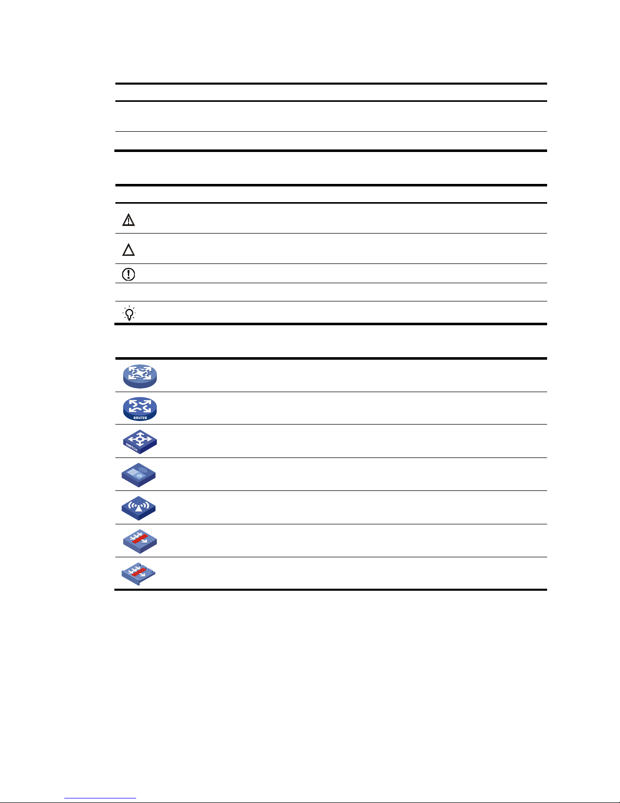
Network topology icons
Represents a generic network device, such as a router, switch, or firewall.
Represents a routing-capable device, such as a router or Layer 3 switch.
Represents a generic switch, such as a Layer 2 or Layer 3 switch, or a router that supports
Layer 2 forwarding and other Layer 2 features.
Represents an access controller, a unified wired-WLAN module, or the switching engine
on a unified wired-WLAN switch.
Represents an access point.
Represents a security product, such as a firewall, a UTM, or a load-balancing or security
card that is installed in a device.
Represents a security card, such as a firewall card, a load-balancing card, or a
NetStream card.
Port numbering in examples
The port numbers in this document are for illustration only and might be unavailable on your device.
About the H3C S5500-HI documentation set
The H3C S5500-HI documentation set includes:
Page 5

Category Documents
Purposes
Product description and
specifications
Marketing brochures Describe product specifications and benefits.
Technology white papers
Provide an in-depth description of software features
and technologies.
Hardware specifications
and installation
Compliance and safety
manual
CE DOCs
Provide regulatory information and the safety
instructions that must be followed during installation.
Installation quick start
Guides you through initial installation and setup
procedures to help you quickly set up your device.
Installation guide
Provides a complete guide to switch installation and
specifications.
LSPM1FAN and
LSPM1FANB Installation
Manual
Describes the appearances, specifications,
installation, and removal of the pluggable fan
modules available for the products.
User manuals for power
modules
Describe the specifications, installation, and
replacement of hot swappable power modules.
RPS Ordering Information
for H3C Low-End Ethernet
Switches
Helps you order RPSs for switches that can work with
an RPS.
User manuals for RPSs
Describe the specifications, installation, and
replacement of RPSs.
User manuals for interface
cards
Describe the specifications, installation, and
replacement of expansion interface cards.
H3C Low End Series
Ethernet Switches
Pluggable Modules
Manual
Describes the specifications of pluggable transceiver
modules.
Pluggable SFP[SFP+][XFP]
Transceiver Modules
Installation Guide
Describe the installation, and replacement of
SFP/SFP+/XFP transceiver modules.
Software configuration
Configuration guides
Describe software features and configuration
procedures.
Command references
Provide a quick reference to all available
commands.
Operations and
maintenance
H3C Series Ethernet
Switches Login Password
Recovery Manual
Helps you deal with switch login password loss.
Release notes
Provide information about the product release,
including the version history, hardware and software
compatibility matrix, version upgrade information,
technical support information, and software
upgrading.
Page 6

Obtaining documentation
You can access the most up-to-date H3C product documentation on the World Wide Web
at http://www.h3c.com
.
Click the links on the top navigation bar to obtain different categories of product documentation:
[Technical Support & Documents > Technical Documents]
—Provides hardware installation, software
upgrading, and software feature configuration and maintenance documentation.
[Products & Solutions]
—Provides information about products and technologies, as well as solutions.
[Technical Support & Documents > Software Download]
—Provides the documentation released with the
software version.
Technical support
service@h3c.com
http://www.h3c.com
Documentation feedback
You can e-mail your comments about product documentation to info@h3c.com.
We appreciate your comments.
Page 7

i
Contents
Preparing for installation ············································································································································· 1
Safety recommendations ·················································································································································· 1
Examining the installation site ········································································································································· 1
Temperature/humidity ············································································································································· 1
Cleanness ·································································································································································· 2
EMI ············································································································································································· 2
Laser safety ································································································································································ 3
Installing the switch ······················································································································································ 4
Installing the switch in a 19-inch rack ····························································································································· 5
Rack-mounting restrictions and guidelines ············································································································· 5
Mounting accessory kit ············································································································································ 6
Rack-mounting by using front mounting brackets (S5500-34C-HI, S5500-58C-HI, and S5500-34F-HI) ······· 8
Rack-mounting by using front and rear mounting brackets (S5500-34C-PWR-HI and S5500-58C-PWR-HI)
················································································································································································ 10
Rack-mounting by using front and rear mounting brackets (S5500-28SC-HI and S5500-52SC-HI) ··········· 12
Rack-mounting by using front mounting brackets and mounting rail assemblies (S5500-28SC-HI and
S5500-52SC-HI) ···················································································································································· 15
Mounting the switch on a workbench ·························································································································· 19
Grounding the switch ···················································································································································· 19
Grounding the switch with a grounding strip ····································································································· 19
Grounding the switch with a grounding conductor buried in the earth ground ············································· 22
Grounding the switch by using the AC power cord ·························································································· 22
Installing/removing a fan tray ······································································································································ 23
Installing a fan tray ··············································································································································· 23
Removing a fan tray ·············································································································································· 24
Installing/removing a power module ··························································································································· 24
Installing a PSR150 series power module ·········································································································· 25
Removing a PSR150 series power module ········································································································· 26
Installing a PSR360-56A/PSR720-56A/PSR1110-56A power module ························································· 26
Removing a PSR360-56A/PSR720-56A/PSR1110-56A power module ························································ 27
Connecting the power cord ·········································································································································· 29
Connecting the PSR150-A/PSR150-A1 ·············································································································· 30
Connecting the PSR150-D/PSR150-D1 ·············································································································· 31
Connecting the PSR360-56A/PSR720-56A/PSR 1110-56A ············································································ 31
Installing/removing an interface card ························································································································· 32
Installing an interface card ··································································································································· 32
Removing an interface card ································································································································· 34
Installing/removing a CX4/SFP+ cable ·············································································································· 34
Verifying the installation ················································································································································ 35
Accessing the switch for the first time ······················································································································· 36
Setting up the configuration environment ···················································································································· 36
Connecting the console cable ······································································································································ 36
Console cable ························································································································································ 36
Connection procedure ·········································································································································· 36
Setting terminal parameters ·········································································································································· 37
Powering on the switch·················································································································································· 40
Page 8

ii
Setting up an IRF fabric ············································································································································· 41
IRF fabric setup flowchart ·············································································································································· 42
Planning IRF fabric setup ··············································································································································· 43
Planning IRF fabric size and the installation site ································································································ 43
Identifying the master switch and planning IRF member IDs ············································································ 43
Planning IRF topology and connections ·············································································································· 44
Identifying physical IRF ports on the member switches ····················································································· 45
Planning the cabling scheme ······························································································································· 46
Configuring basic IRF settings ······································································································································· 48
Connecting the physical IRF ports ································································································································ 48
Accessing the IRF fabric to verify the configuration ··································································································· 48
Maintenance and troubleshooting ···························································································································· 50
Power module failure ····················································································································································· 50
Fan failure ······································································································································································· 50
Configuration terminal problems ·································································································································· 51
Appendix A Chassis views and technical specifications ························································································ 52
Chassis views ································································································································································· 52
S5500-34C-HI ······················································································································································· 52
S5500-58C-HI ······················································································································································· 53
S5500-34F-HI ························································································································································ 54
S5500-34C-PWR-HI ·············································································································································· 55
S5500-58C-PWR-HI ·············································································································································· 56
S5500-28SC-HI ····················································································································································· 57
S5500-52SC-HI ····················································································································································· 58
Technical specifications ················································································································································· 59
Cooling system ······························································································································································· 63
Cooling system of the S5500-28SC-HI and S5500-52SC-HI ··········································································· 63
Cooling system of the other models in the switch series ··················································································· 63
Appendix B FRUs and compatibility matrixes ·········································································································· 65
FRUs and compatibility matrixes ·································································································································· 65
Hot swappable power modules···································································································································· 66
Hot swappable fan trays ··············································································································································· 67
Interface cards ································································································································································ 68
SFP/SFP+/XFP transceiver modules and SFP+/CX4 cables ····················································································· 68
100 Mbps SFP transceiver modules ···················································································································· 69
1000 Mbps SFP transceiver modules ················································································································· 69
10 Gbps SFP+ transceiver modules/SFP+ cables ····························································································· 70
10 Gbps XFP transceiver modules ······················································································································· 71
CX4 cables ····························································································································································· 71
Appendix C Ports and LEDs ······································································································································ 72
Fixed ports ······································································································································································ 72
Console port ·························································································································································· 72
Management Ethernet port ··································································································································· 72
10/100/1000Base-T Ethernet port ···················································································································· 72
100/1000Base-X SFP port ··································································································································· 73
Combo interface ···················································································································································· 73
SFP+ port ································································································································································ 73
LEDs ················································································································································································· 73
System status LED··················································································································································· 73
Power module status LED ······································································································································ 74
Port mode LED ························································································································································ 74
Seven-segment LED ················································································································································ 74
Page 9

iii
Management Ethernet port LED ··························································································································· 76
10/100/1000Base-T Ethernet port LED ············································································································· 77
100/1000Base-X SFP port LED ··························································································································· 78
SFP+ port LED ························································································································································ 78
Interface card status LED ······································································································································· 79
Port LED on the interface card ······························································································································ 79
I/O status LED on the power module ·················································································································· 79
Index ··········································································································································································· 80
Page 10

1
Preparing for installation
Safety recommendations
To avoid any equipment damage or bodily injury, read the following safety recommendations before
installation. Note that the recommendations do not cover every possible hazardous condition.
• Before cleaning the switch, remove all power cords from the switch. Do not clean the switch with wet
cloth or liquid.
• Do not place the switch near water or in a damp environment. Prevent water or moisture from
entering the switch chassis.
• Do not place the switch on an unstable case or desk. The switch might be severely damaged in case
of a fall.
• Ensure good ventilation of the equipment room and keep the air inlet and outlet vents of the switch
free of obstruction.
• Connect the yellow-green protection grounding cable before power-on.
• Make sure the operating voltage is in the required range.
• To avoid electrical shocks, do not open the chassis while the switch is operating or when the switch
is just powered off.
• When replacing FRUs, including interface cards and power modules, wear an ESD wrist strap to
avoid damaging the units.
Examining the installation site
The S5500-HI switches must be used indoors. You can mount your switch in a rack or on a workbench,
but make sure:
• Adequate clearance is reserved at the air inlet and exhaust vents for ventilation.
• The rack or workbench has a good ventilation system.
• Identify the hot aisle and cold aisle at the installation site, and make sure ambient air flows into the
switch from the cold aisle and exhausts to the hot aisle.
• Identify the airflow designs of neighboring devices, and prevent hot air flowing out of the bottom
device from entering the top device.
• The rack is sturdy enough to support the switch and its accessories.
• The rack or workbench is correctly grounded.
To ensure normal operation and long service life of your switch, install it in an environment that meets the
requirements described in the following subsections.
Temperature/humidity
Maintain appropriate temperature and humidity in the equipment room.
Page 11

2
• Lasting high relative humidity can cause poor insulation, electricity creepage, mechanical property
change of materials, and metal corrosion.
• Lasting low relative humidity can cause washer contraction and ESD and bring problems including
loose captive screws and circuit failure.
• High temperature can accelerate the aging of insulation materials and significantly lower the
reliability and lifespan of the switch.
For the temperature and humidity requirements, see "Appendix A Chassis views and technical
spec
ifications."
Cleanness
Dust buildup on the chassis might result in electrostatic adsorption, which causes poor contact of metal
components and contact points, especially when indoor relative humidity is low. In the worst case,
electrostatic adsorption can cause communication failure.
Table 1 Dust concentration limit in the equipment room
Substance Concentration limit (particles/m³)
Dust
≤ 3 x 10⁴ (no visible dust on the tabletop over three days)
NOTE:
Dust diameter ≥ 5 μm
The equipment room must also meet limits on salts, acids, and sulfides to eliminate corrosion and
premature aging of components, as shown in Table 2.
Table 2 Harmful gas li
mits in the equipment room
Gas Maximum concentration (mg/m
3
)
SO
2
0.2
H2S 0.006
NH3 0.05
Cl2 0.01
EMI
Electromagnetic interference (EMI) might be coupled from the source to the switch through the following
coupling mechanisms:
• Capacitive coupling
• Inductive coupling
• Radiative coupling
• Common impedance coupling
• Conductive coupling
To prevent EMI, take the following actions:
Page 12

3
• If AC power is used, use a single-phase three-wire power receptacle with protection earth (PE) to
filter interference from the power grid.
• Keep the switch far away from radio transmitting stations, radar stations, and high-frequency
devices.
• Use electromagnetic shielding, for example, shielded interface cables, when necessary.
• Route interface cables only indoors to prevent signal ports from getting damaged by overvoltage or
overcurrent caused by lightning strikes.
Laser safety
W
ARNING!
Do not stare into any fiber port when the switch has power. The laser li
g
ht emitted from the optical fiber
might hurt your eyes.
The S5500-HI switches are Class 1 laser devices.
Page 13
4
Installing the switch
CAUTION:
Keep the tamper-proof seal on a mountin
g
screw on the chassis cover intact, and if you want to open the
chassis, contact H3C for permission. Otherwise, H3C shall not be liable for any consequence.
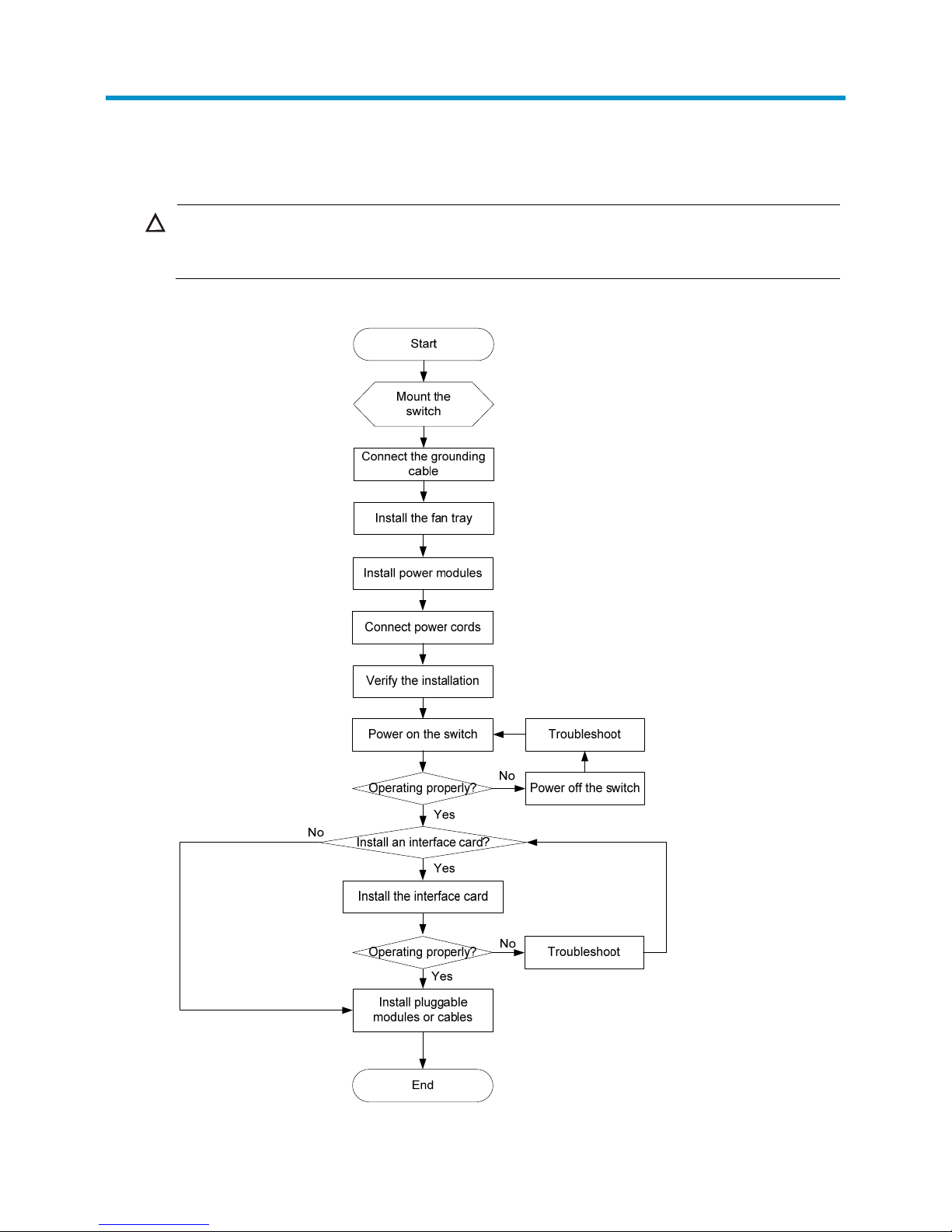
Figure 1 Hardware installation flow
Page 14
5
NOTE:
Only the S5500-28SC-HI and S5500-52SC-HI need a fan tray.
Installing the switch in a 19-inch rack
You can install an S5500-HI switch in a 19-inch rack by using one of the following methods:
• Use the front mounting brackets. Figure 2 sh
ows the mounting procedure diagram.
• Use the front and rear mounting brackets. Figure 3 sh
ows the mounting procedure diagram.
• Use the front mounting brackets and mounting rail assemblies. Figure 4 sh
ows the mounting
procedure diagram.
NOTE:
If a rack shelf is available, you can put the switch on the rack shelf, slide the switch to an appropriate
position, and attach the switch to the rack with mounting brackets.
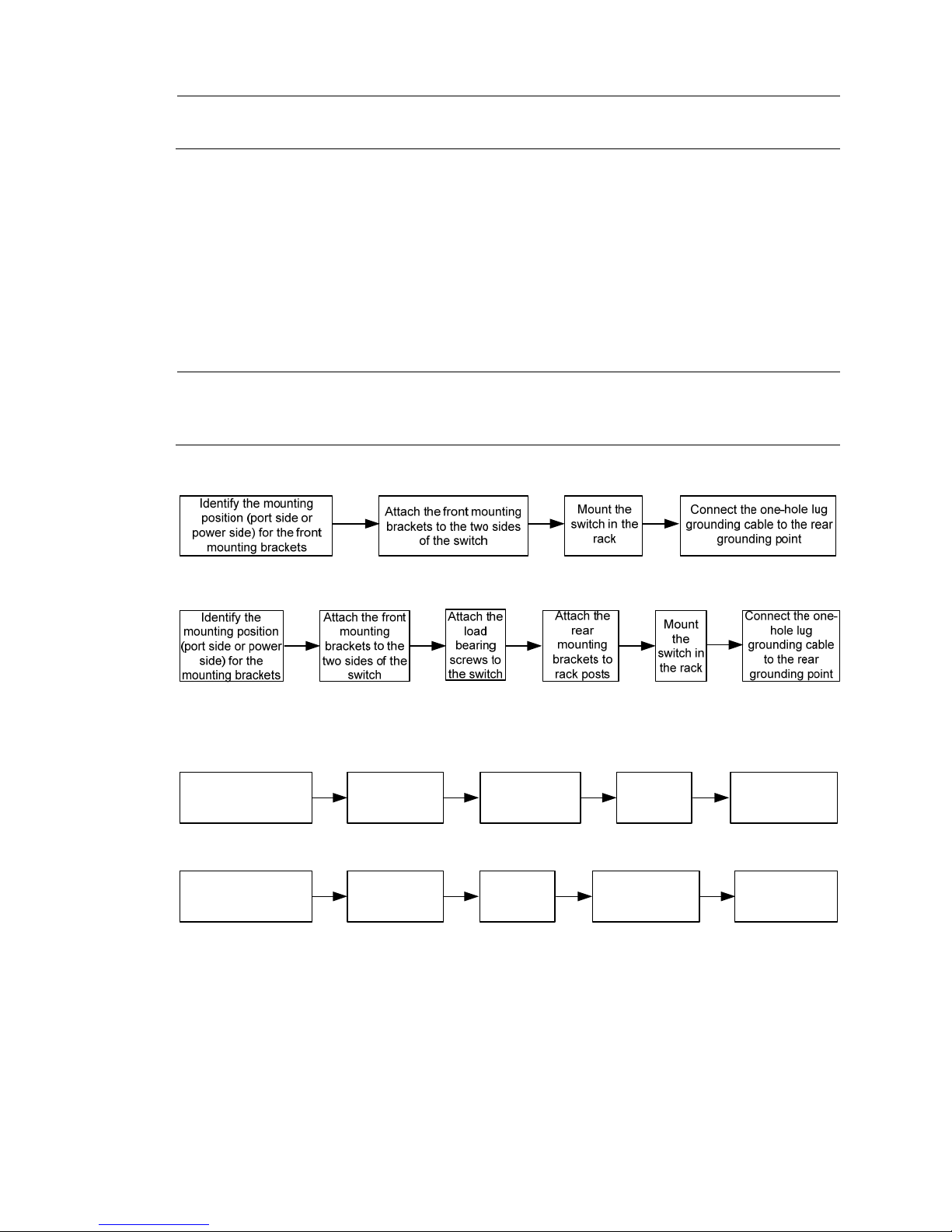
Figure 2 Rack-mounting procedure (1)
Figure 3 Rack-mounting procedure (2)
Figure 4 Rack-mounting procedure (3)
Rack-mounting restrictions and guidelines
Follow the rack-mounting restrictions and guidelines in Table 3, depending on the mounting accessories
that you use.
Attach the
chassis rails to
the two sides of
the chassis
Connect the two-
hole lug grounding
cable to the side
grounding point
Attach the
slide rails to
the rack
Install the front
mounting brackets in
the mounting position
near the power modules
Mount the
chassis in the
rack
Attach the
chassis rails to
the two sides of
the chassis
Attach the
slide rails to
the rack
Install the front
mounting brackets in
the mounting position
near the power modules
Mount the
chassis in the
rack
Connect the one-
hole lug grounding
cable to the rear
grounding point
(Approach 1) Use side grounding point:
(Approach 2) Use rear grounding point:
Page 15

6
Table 3 Rack-mounting restrictions and guidelines
Switch model Mounting method Restrictions and guidelines
S5500-34C-HI
S5500-58C-HI
S5500-34F-HI
Rack-mounting by using front
mounti
ng brackets
(S5500-34C-HI,
S5500-58C-HI, and
S5500-34F-HI)
• Install the front mounting brackets at the port-side or
power-side mounting position as needed.
• For the S5500-58C-HI, if you are installing an
LSP5GP8P0 interface card, make sure the rack
depth is 800 mm (31.50 in) or 1000 mm (39.37 in).
S5500-34C-PWR-HI
S5500-58C-PWR-HI
Rack-mounting by using front
and rear mounting brackets
(S5500-34C-PWR-HI and
S5500-58C-PWR-HI)
• Install the front mounting brackets at the port-side or
power-side mounting position as needed.
• Make sure the rack depth is 800 mm (31.50 in) or
1000 mm (39.37 in).
S5500-28SC-HI
S5500-52SC-HI
Rack-mounting by using front
and rear mounti
ng brackets
(S5500-28SC-HI and
S5500-52SC-HI)
• Install the front mounting brackets at the port-side
and the load-bearing screw at the power-side.
• Make sure the rack depth is between 389 mm
(15.32 in) and 555 mm (21.85 in).
• Use the grounding port at the rear panel for
grounding.
• H3C recommends that you use this installation
method for enterprise networking.
Rack-mounting by using front
mounting brackets and
mounting rail assemblies
(S5500-28SC-HI and
S5500-52SC-HI)
• Install the front mounting brackets at the power-side
and the rack mounting rail kit at the port-side.
• Make sure the rack depth is between 612 mm
(24.09 in) and 832 mm (32.76 in).
• Choose side grounding point or rear grounding
point as needed. If you use side grounding point,
connect the two-hole lug grounding cable to the side
grounding point on the chassis.
• H3C recommends that you use this installation
method for data center networking.
Mounting accessory kit
Accessories
S5500-34C-HI
S5500-58C-HI
S5500-34F-HI
S5500-34C-PWR-HI
S5500-58C-PWR-HI
S5500-28SC-HI
S5500-52SC-HI
One pair of 1U front mounting
brackets (See Figure 5)
Supplied with the
switch
Supplied with the
switch
Supplied with the
switch
One pair of 1U rear mounting
brackets, two load-bearing screws
(See Figure 6.)
N/A
Supplied with the
switch
Supplied with the
switch
One pair of chassis rails and one pair
of slide rails (See Figure 7)
N/A N/A Optional
Grounding cable with a one-hole lug
(for connecting to the rear grounding
point)
Supplied with the
switch
Supplied with the
switch
Supplied with the
switch
Page 16

7
Accessories
S5500-34C-HI
S5500-58C-HI
S5500-34F-HI
S5500-34C-PWR-HI
S5500-58C-PWR-HI
S5500-28SC-HI
S5500-52SC-HI
Grounding cable with a two-hole lug
(for connecting to the side grounding
point)
N/A N/A Optional
Figure 5 Front mounting bracket
(1) Hole for attaching to a rack
(2) Hole for attaching to the switch chassis
Figure 6 Rear mounting bracket and load-bearing screw
(1) Hole for attaching to a rack (2) Load-bearing screw
Page 17
8
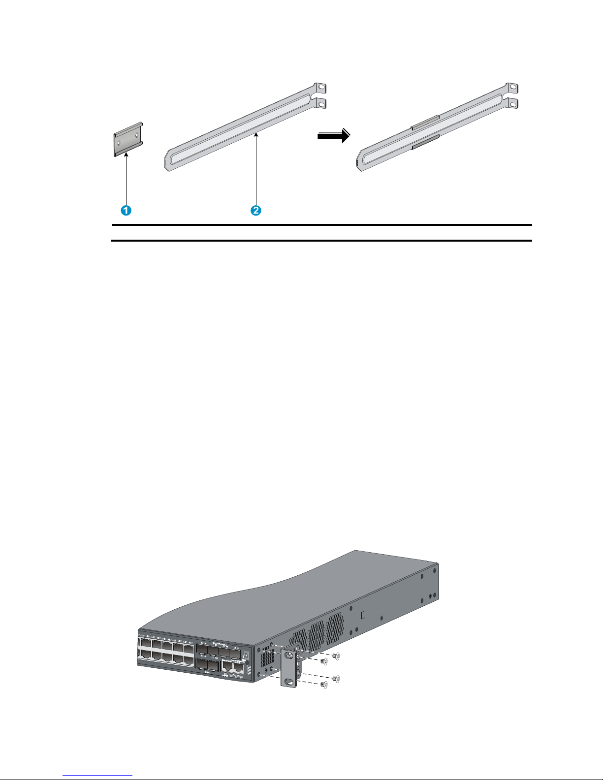
Figure 7 Rack mounting rail kit
(1) Chassis rail (2) Slide rail
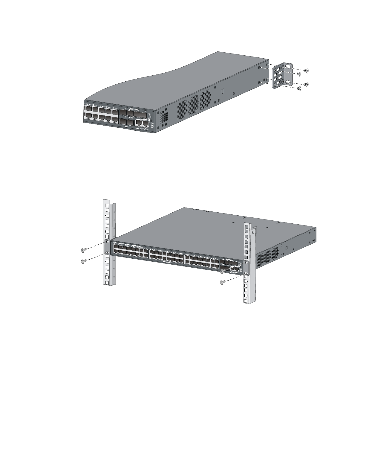
Rack-mounting by using front mounting brackets
(S5500-34C-HI, S5500-58C-HI, and S5500-34F-HI)
This mounting method is applicable to only the S5500-34C-HI, S5500-58C-HI, and S5500-34F-HI
switches.
This task requires two people.
To install the switch in a 19-inch rack by using the front mounting brackets:
1. Identify the mounting positions.
2. Wear an ESD wrist strap and make sure it makes good skin contact and is correctly grounded.
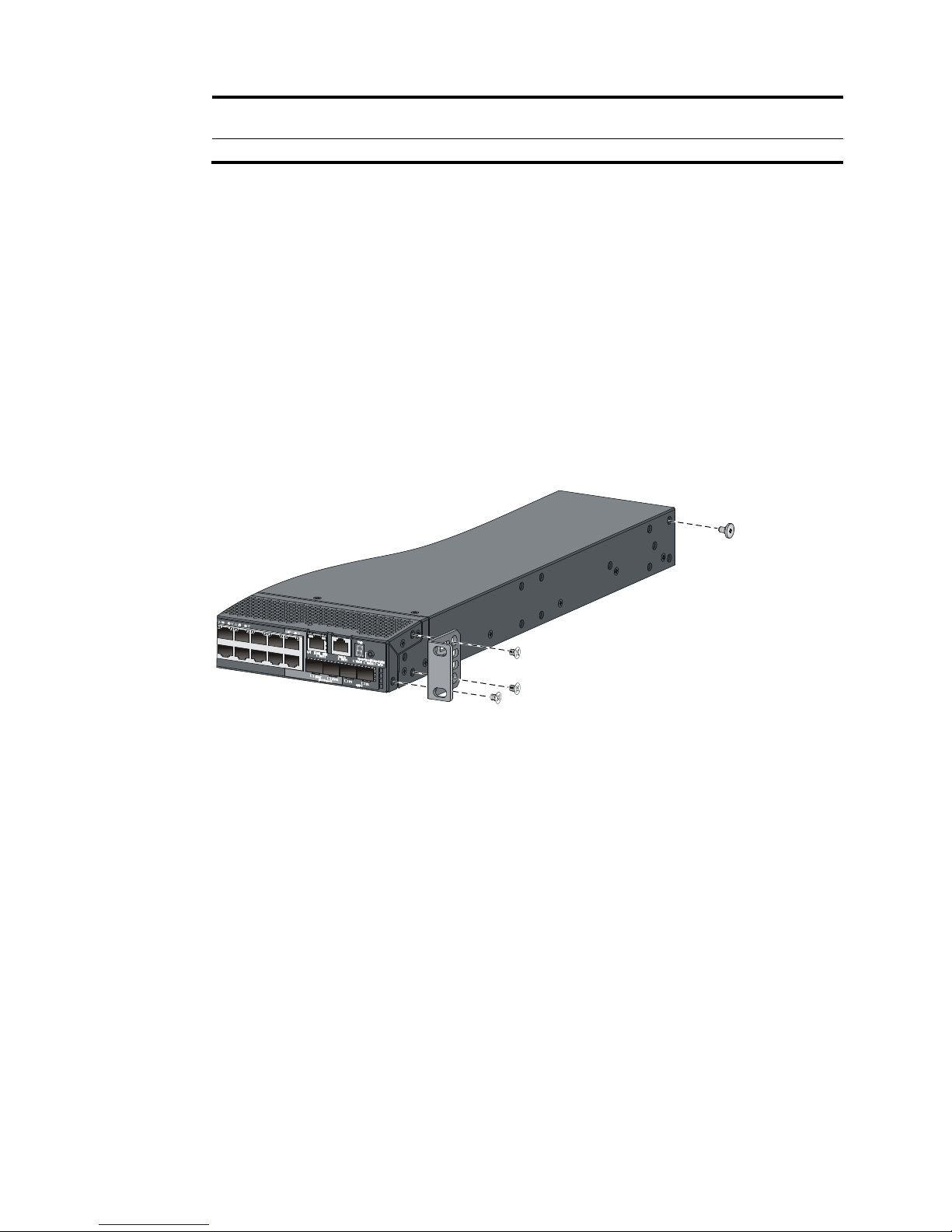
3. Attach the front mounting brackets to the chassis:
a. Unpack the front mounting brackets and the M4 screws (supplied with the switch) for attaching
the brackets to the switch chassis.
b. Align the round holes in the wide flange of one front mounting bracket with the screw holes in
the port-side mounting position (see Figure 8) or power-side mou
nting position (see Figure 9).
c. Use M4 screws to attach the mounting bracket to the chassis.
d. Repeat the proceeding two steps to attach the other mounting bracket to the chassis.
Figure 8 Attaching the front mounting bracket to the port side
Page 18
9
Figure 9 Attaching the front mounting bracket to the power side
4. Mount the chassis to the rack:
a. One person supports the chassis bottom with one hand, holds the front part of the chassis with
the other hand, and pushes the chassis into the rack gently
b. The other person uses M6 screws and cage nuts (u ser supplied) to attac h the switch to the rac k.
Figure 10 Mounting the switch to the rack (front mounting brackets at the port side)
Page 19
10
Figure 11 Mounting the switch to the rack (front mounting brackets at the power side)
5. Connect the one-hole lug grounding cable to the rear grounding point (see "Connecting the rear
grounding point to a grounding strip").
Rack-mounting by using front and rear mounting brackets
(S5500-34C-PWR-HI and S5500-58C-PWR-HI)
This mounting method is applicable to only the S5500-34C-PWR-HI and S5500-58C-PWR-HI switches.
You can install the front mounting brackets at the port-side or power-side mounting position as needed.
The following takes port-side mounting as an example. The power-side mounting is similar.
This task requires two people.
To install the switch in a 19-inch rack by using the front and rear mounting brackets:
1. Wear an ESD wrist strap and make sure it makes good skin contact and is correctly grounded.
2. Attach the front mounting brackets and load-bearing screws to the chassis:
a. Unpack the front mounting brackets and the M4 screws for attaching the brackets to the switch
chassis.
b. Align the round holes in the wide flange of one front mounting bracket with the screw holes in
the port-side mounting position on one side of the chassis (see Figure 12).
c. Use M4
screws (supplied with the switch) to attach the mounting bracket to the chassis.
d. Repeat the proceeding two steps to attach the other mounting bracket to the chassis.
e. Unpack the load-bearing screws.
f. Install the load-bearing screws in one of the load-bearing screw mounting positions (see Figure
12) as need
ed.
Page 20
11
Figure 12 Attaching the front mounting brackets and load-bearing screws to the chassis
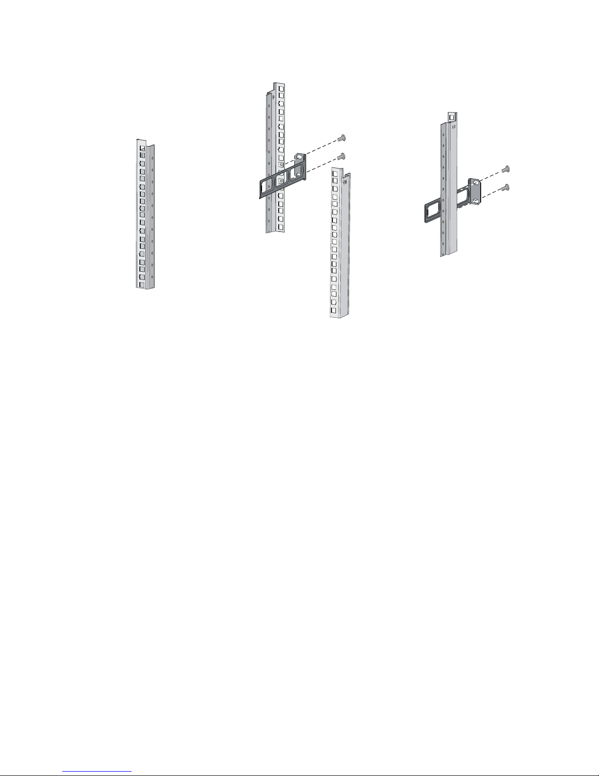
3. Attach the rear mounting brackets to the rack:
a. Unpack the rear mounting brackets.
b. Install cage nuts (user-supplied) in the mounting holes in the rear rack posts.
c. Attach the rear mounting brackets to the rear posts with M6 screws (user supplied), as shown
in Figure 13.
Figure 13 Attaching th
e rear mounting brackets to a rack
4. Mount the switch chassis in the rack:
a. One person supports the chassis bottom with one hand, holds the front part of the chassis with
the other hand, and pushes the chassis into the rack gently.
Make sure the load-bearing screws closely contact with the upper edges of the rear mounting
brackets, as shown in Figure 14.
b. The oth
er person aligns the oval holes in the front brackets with the mounting holes in the front
rack posts, and attaches the front mounting brackets with M6 screws (user supplied) to the front
rack posts.
Page 21
12
Make sure the front and rear mounting brackets have securely attached the switch to the rack.
Figure 14 Mounting the switch in the rack
5. Connect the one-hole lug grounding cable to the rear grounding point (see "Connecting the rear
grounding point to a grounding strip").
Rack-mounting by using front and rear mounting brackets
(S5500-28SC-HI and S5500-52SC-HI)
This mounting method is applicable to only the S5500-28SC-HI and S5500-52SC-HI switches.
This task requires two people.
To install the switch in a 19-inch rack by using the front and rear mounting brackets:
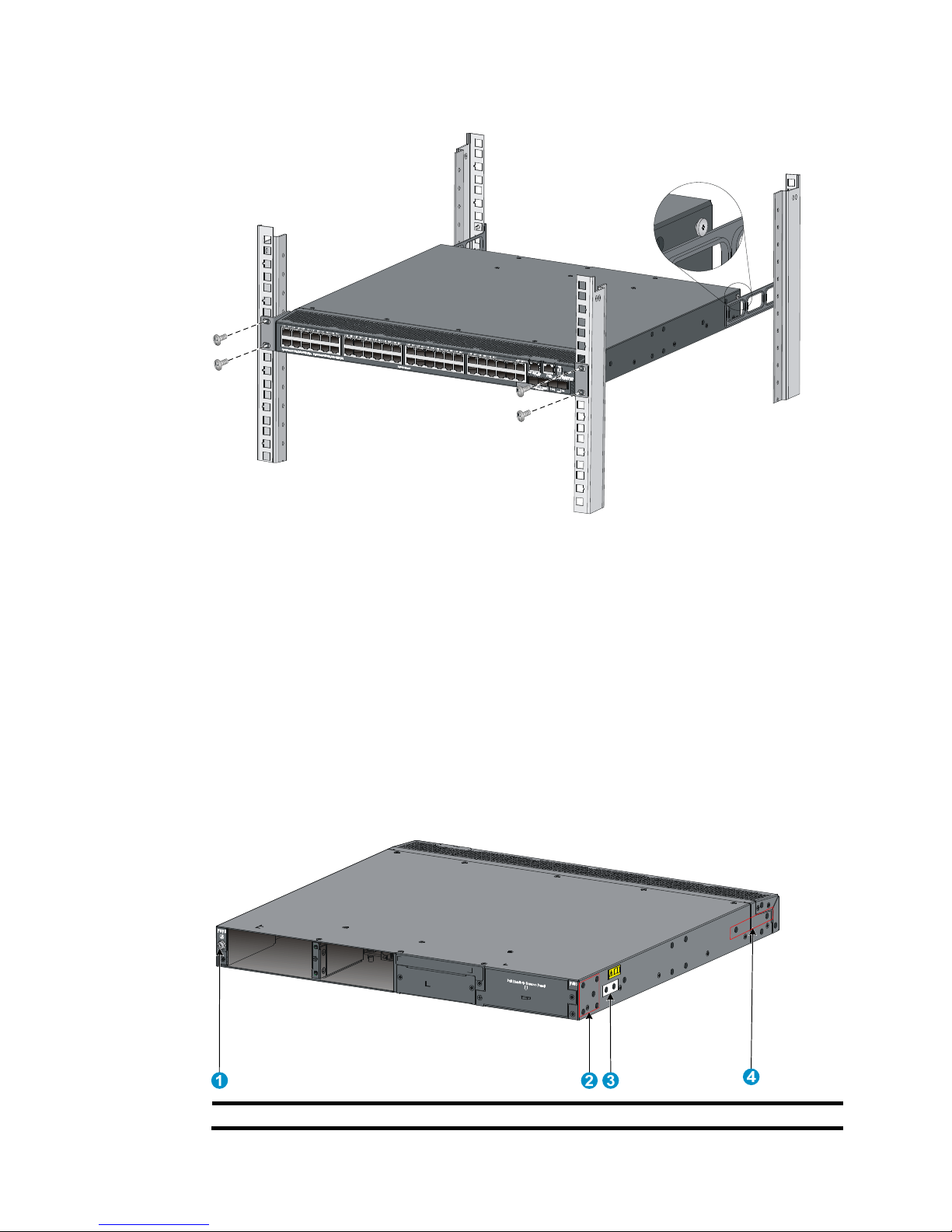
1. Identify the mounting and grounding positions.
Figure 15 Identifying the mounting and grounding positions
Page 22
13
(1) Rear grounding point (2) Load-bearing screw mounting positions (choose
one of the two holes)
(3) Port-side front bracket mounting position
2. Wear an ESD wrist strap and make sure it makes good skin contact and is correctly grounded.
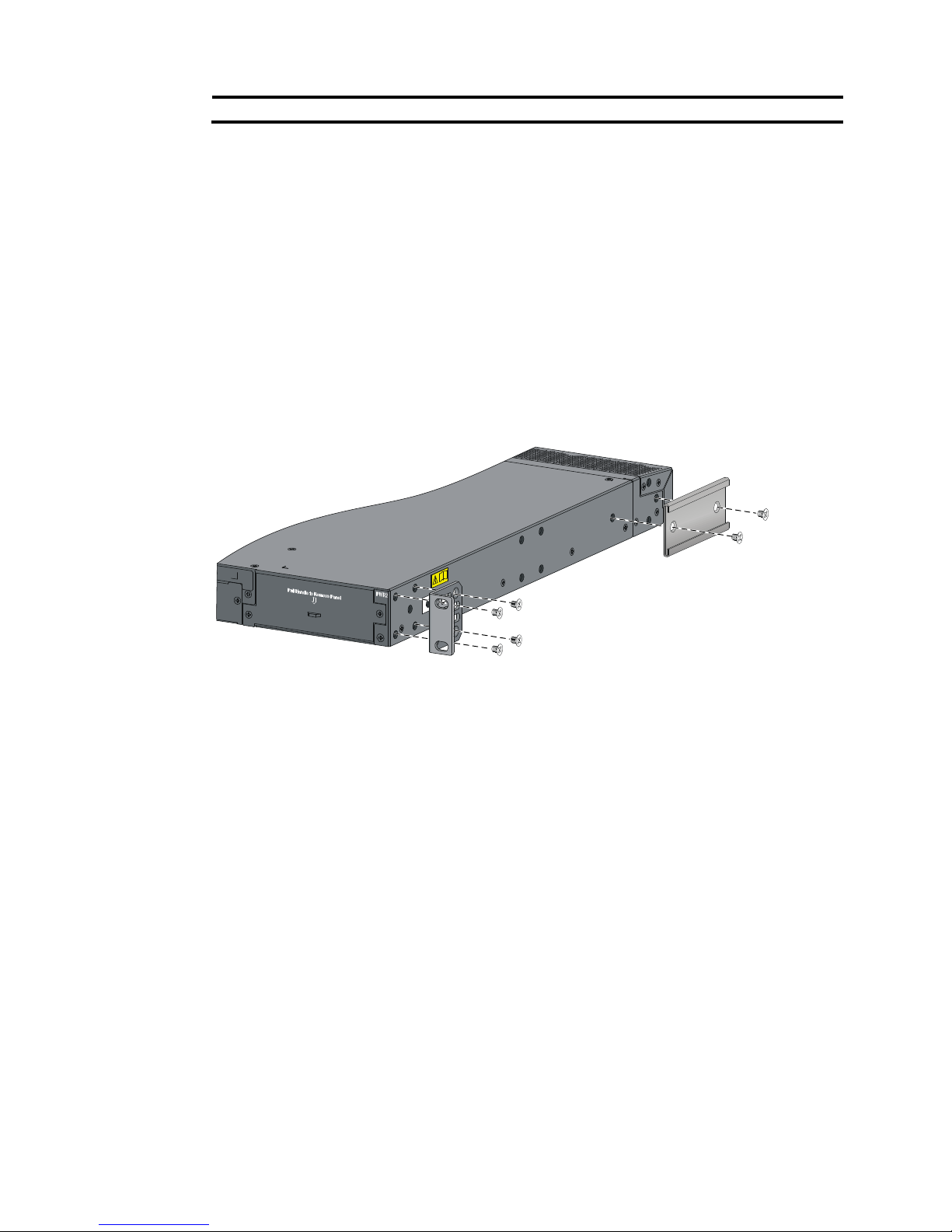
3. Attach the front mounting brackets and load-bearing screws to the chassis:
a. Unpack the front mounting brackets and the M4 screws for attaching the brackets to the switch
chassis.
b. Align the round holes in the wide flange of one front mounting bracket with the screw holes in
the port-side mounting position on one side of the chassis (see Figure 16).
c. Use M4
screws (supplied with the switch) to attach the mounting bracket to the chassis.
d. Repeat the proceeding two steps to attach the other mounting bracket to the chassis.
e. Unpack the rear mounting brackets and the load-bearing screws.
f. Install the load-bearing screws in one of the load-bearing screw mounting positions (see Figure
16) as need
ed.
Figure 16 Attaching the front mounting brackets and load-bearing screws to the chassis
4. Attach the rear mounting brackets to the rack:
a. Unpack the rear mounting brackets.
b. Install cage nuts (user-supplied) in the mounting holes in the rear rack posts.
c. Attach the rear mounting brackets to the rear posts with M6 screws (user supplied), as shown
in Figure 13.
Page 23
14
Figure 17 Attaching the rear mounting brackets to a rack
5. Mount the switch chassis in the rack:
a. One person supports the chassis bottom with one hand, holds the front part of the chassis with
the other hand, and pushes the chassis into the rack gently.
Make sure the load-bearing screws closely contact with the upper edges of the rear mounting
brackets, as shown in Figure 14.
b. The oth
er person aligns the oval holes in the front brackets with the mounting holes in the front
rack posts, and attaches the front mounting brackets with M6 screws (user supplied) to the front
rack posts.
Make sure the front and rear mounting brackets have securely attached the switch to the rack.
Page 24
15
Figure 18 Mounting the switch in the rack
6. Connect the one-hole lug grounding cable to the rear grounding point (see "Connecting the rear
grounding point to a grounding strip").
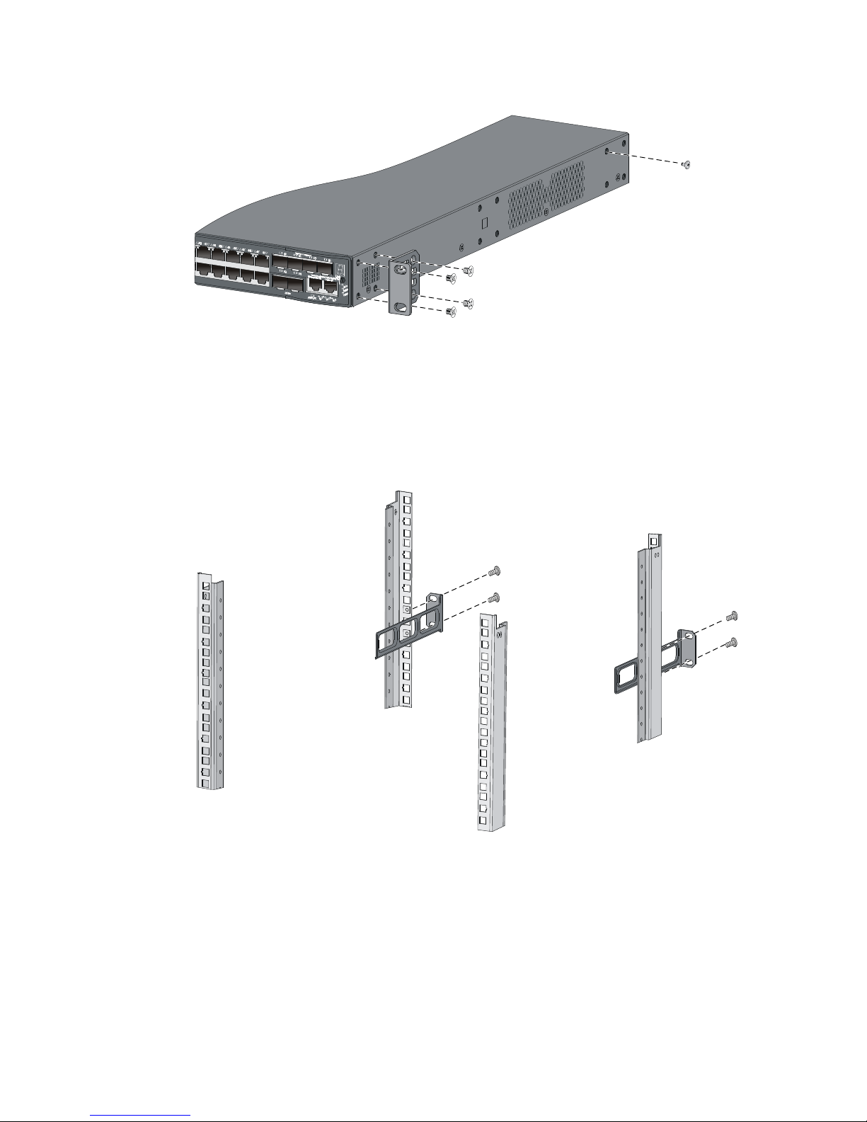
Rack-mounting by using front mounting brackets and mounting
rail assemblies (S5500-28SC-HI and S5500-52SC-HI)
This mounting method is applicable to only the S5500-28SC-HI and S5500-52SC-HI switches.
This task requires two people.
To install the switch in a 19-inch rack by using the front mounting brackets and mounting rail assemblies:
1. Identify the mounting and grounding positions.
Figure 19 Identifying the mounting and grounding positions
(1) Rear grounding point (2) Power-side front bracket mounting position
Page 25
16
(3) Side
g
rounding point (4) Chassis rail mounting position
2. Wear an ESD wrist strap and make sure it makes good skin contact and is well grounded.
3. Attach the front mounting brackets and the chassis rails to the chassis (see Figure 20):
a. Unpac
k the front mounting brackets and the M4 screws for attaching the brackets to the switch
chassis.
b. Align the round holes in the wide flange of one front mounting bracket with the screw holes in
the power-side mounting position on one side of the chassis.
c. Use M4 screws (supplied with the switch) to attach the mounting bracket to the chassis.
d. Align one chassis rail with the screw holes in the chassis rail mounting position.
e. Use M4 screws (supplied with the switch) to attach the chassis rail to the chassis.
f. Repeat the proceeding steps to attach the other mounting bracket and chassis rail to the other
side of the chassis.
Figure 20 Attaching the front mounting brackets and chassis rails to the chassis
4. Choose a grounding point.
{ If the side grounding point is used, go to the next step.
{ If the rear grounding point is used, skip the next step.
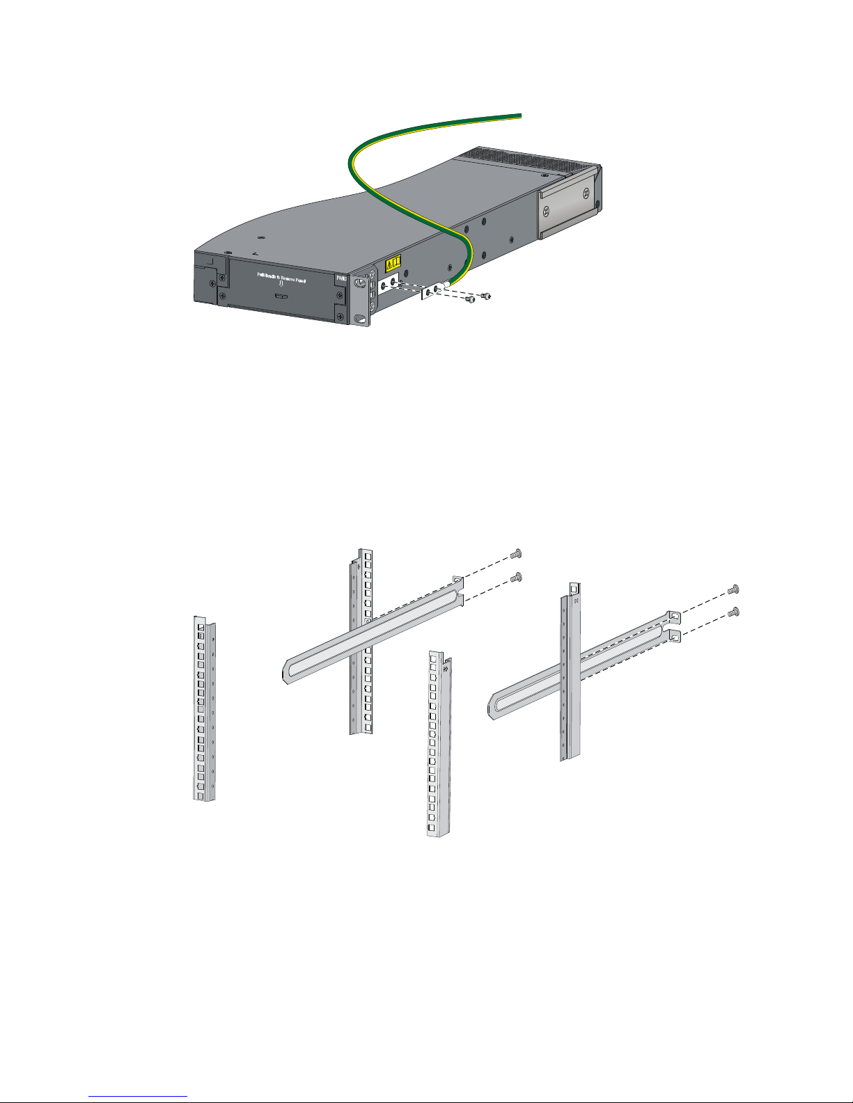
5. Connect the two-hole lug grounding cable to the side grounding point on the chassis:
a. Unpack the grounding cable and grounding screws.
b. Align the two-hole grounding lug at one end of the cable with the grounding holes of the
grounding point, insert the grounding screws into the holes, and tighten the screws with a
screwdriver to attach the grounding lug to the chassis, as shown in Figure 21.
Page 26
17
Figure 21 Attaching the grounding cable to the chassis
6. Attach the slide rails to the rack:
a. Identify the rack attachment position for the slide rails.
b. Install cage nuts (user-supplied) in the mounting holes in the rack posts.
c. Align the screw holes in one slide rail with the cage nuts in the rack post on one side, and use
M6 screws (user supplied) to attach the slide rail to the rack, as shown in Figure 22.
d. Repeat the pr
eceding step to attach the other slide rail to the rack post on the other side.
Keep the two slide rails at the same height so the slide rails can attach into the chassis rails.
Figure 22 Installing the slide rails
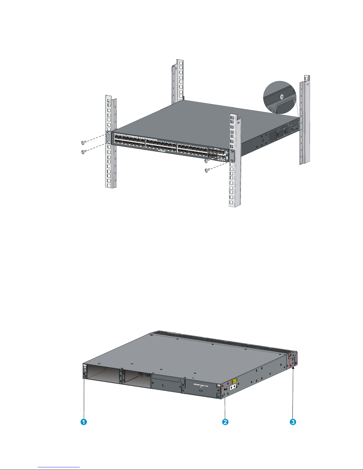
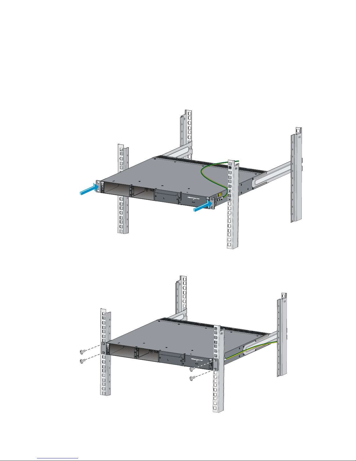
7. Mount the switch in the rack:
a. Verify that the front mounting brackets and chassis rails have been securely attached to the
switch chassis.
b. Verify that the slide rails have been correctly attached to the rear rack posts.
c. Install cage nuts (user-supplied) to the front rack posts and make sure they are at the same level
as the slide rails.
Page 27
18
d. Supporting the bottom of the switch, align the chassis rails with the slide rails on the rack posts,
as shown in Figure 23. Wo
rk with another person to slide the chassis rails along the slide rails
until the mounting brackets are flush with the rack posts.
e. Use M6 screws (user-supplied) to attach the mounting brackets to the rack, as shown in Figure
24.
T
o secure the switch in the rack, make sure the front ends of the slide rails reach out of the
chassis rails.
Figure 23 Mounting the switch in the rack (1)
Figure 24 Mounting the switch in the rack (2)
Page 28

19
8. If you are using the rear grounding point, connect the one-hole lug grounding cable to the rear
grounding point as described in "Connecting the rear grounding point to a grounding strip." If not,
skip this step.
Mounting the switch on a workbench
IMPORTANT:
• Ensure good ventilation and 10 cm (3.9 in) of clearance around the chassis for heat dissipation.
• Avoid placing heavy objects on the switch.
To mount the switch on a workbench:
1. Verify that the workbench is sturdy and well grounded.
2. Place the switch with bottom up, and clean the round holes in the chassis bottom with dry cloth.
3. Attach the rubber feet to the four round holes in the chassis bottom.
4. Place the switch with upside up on the workbench.
Grounding the switch
W
ARNING!
Correctly connecting the switch grounding cable is crucial to lightning protection and EMI protection.
The power input end of the switch has a noise filter, whose central ground is directly connected to the
chassis to form the chassis ground (commonly known as PGND). You must securely connect this chassis
ground to the earth so the faradism and leakage electricity can be safely released to the earth to
minimize EMI susceptibility of the switch.
You can ground the switch in one of the following ways, depending on the grounding conditions
available at the installation site:
• Grounding the switch with a grounding strip
• Grounding the switch with a grounding conductor buried in the earth ground
• Grounding the switch by using the AC power cord
NOTE:
The power and grounding terminals in this section are for illustration only.
Grounding the switch with a grounding strip
W
ARNING!
Connect the
g
rounding cable to the grounding system in the equipment room. Do not connect it to a fire
main or lightning rod.
If a grounding strip is available at the installation site, connect the grounding cable to the grounding
strip.
Page 29

20
Connecting the rear grounding point to a grounding strip
1. Remove the grounding screw from the rear panel of the switch chassis.
2. Use the grounding screw to attach the ring terminal of the grounding cable to the grounding screw
hole.
IMPORTANT:
Orient the grounding cable as shown in Figure 25 so yo
u can easily install or remove power modules.
Figure 25 Connecting the grounding cable to the chassis
(1) Grounding cable (2) Grounding sign
(3) Grounding hole (4) Ring terminal
(5) Grounding screw
3. Verify that the grounding cable has been securely connected to the rear grounding point.
4. Remove the hex nut of a grounding post on the grounding strip.
5. Cut the grounding cable as appropriate for connecting to the grounding strip.
6. Peel 5 mm (0.20 in) of insulation sheath by using a wire stripper, and insert the bare metal part
through the black insulation covering into the end of the ring terminal supplied with the switch.
7. Secure the metal part of the cable to the ring terminal with a crimper, cover the joint with the
insulation covering, and heat the insulation covering with a blow dryer to completely cover the
metal part.
Figure 26 Attaching a ring terminal to the grounding cable
8. Connect the ring terminal to the grounding post of the grounding strip, and fasten it with the
removed hex nut.
1
2
3
4
5
Page 30

21
Figure 27 Connecting the grounding cable to a grounding strip
(1) Grounding post (2) Grounding strip
(3) Grounding cable (4) Hex nut
Connecting the side grounding point to a grounding strip
This method is applicable to only the S5500-28SC-HI and S5500-52SC-HI switches.
To connect the side grounding point to a grounding strip:
1. Attach the two-hole grounding lug at one end of the grounding cable to a grounding point on the
switch chassis.
2. Remove the hex nut of a grounding post on the grounding strip.
3. Attach the ring terminal at the other end of the grounding cable to the grounding strip through the
grounding post, and fasten the ring terminal with the removed hex nut.
Figure 28 Connecting the grounding cable to a grounding strip
(1) Hex nut (2) Ring terminal
(3) Grounding post
(4) Grounding strip
Page 31

22
Grounding the switch with a grounding conductor buried in the
earth ground
If the installation site has no grounding strips, but earth ground is available, hammer a 0.5 m (1.64 ft) or
longer angle iron or steel tube into the earth ground to serve as a grounding conductor.
The dimensions of the angle iron must be at least 50 × 50 × 5 mm (1.97 × 1.97 × 0.20 in). The steel tube
must be zinc-coated and its wall thickness must be at least 3.5 mm (0.14 in).
Weld the yellow-green grounding cable to the angel iron or steel tube and treat the joint for corrosion
protection.
Figure 29 Grounding the switch by burying the grounding conductor into the earth ground
(1) Grounding screw (2) Chassis rear panel
(3) Grounding cable
(4) Earth (5) Joint (6) Grounding conductor
Grounding the switch by using the AC power cord
If the installation site has no grounding strips or earth ground, you ground an AC-powered switch through
the PE wire of the power cord. Make sure:
• The power cord has a PE terminal.
• The ground contact in the power outlet is securely connected to the ground in the power distribution
room or on the AC transformer side.
• The power cord is securely connected to the power outlet.
NOTE:
If the
g
round contact in the power outlet is not connected to the ground, report the problem and reconstruc
t
the grounding system.
Page 32

23
Figure 30 Grounding through the PE wire of the AC power cord
(1) Chassis rear panel (2) Three-wire AC power cord
NOTE:
To guarantee the grounding effect, use the grounding cable provided with the switch to connect to the
grounding strip in the equipment room as long as possible.
Installing/removing a fan tray
Only the S5500-28SC-HI and S5500-52SC-HI switches support hot-swappable fan trays.
CAUTION:
Each of the S5500-28SC-HI and S5500-52SC-HI switches has only one fan tray slot for the
hot-swappable fan tray. To ensure good ventilation, follow these guidelines:
• Do not operate the switch without a fan tray.
• If the fan tray has problems durin
g
operation, replace it within 2 minutes while the switch is operating.
Installing a fan tray
CAUTION:
To prevent damage to the fan tray or the connectors on the backplane, insert the fan tray gently. If you
encounter a hard resistance while inserting the fan tray, pull out the fan tray and insert it again.
To install a fan tray:
1. Wear an ESD wrist strap and make sure it makes good skin contact and is well grounded.
2. Unpack the fan tray and verify that the fan tray model is correct.
3. Grasp the handle of the fan tray with one hand and support the fan tray bottom with the other, and
slide the fan tray along the guide rails into the slot until the fan tray seats in the slot and has a firm
contact with the backplane (see callout 1 in Figure 31).
Page 33

24
4. Fasten the captive screw on the fan tray with a Philips screwdriver until the fan tray is securely
seated in the chassis (see callout 2 in Figure 31).
If the captive
screw cannot be tightly fastened, examine the installation of the fan tray.
Figure 31 Installing an LSPM1FAN fan tray
IMPORTANT:
• At the first login to the switch, use the fan prefer-direction command to set the airflow direction of the
switch to be the same as the airflow direction of the fan tray. If the fan tray has a different airflow
direction than the switch, the system outputs traps and logs to notify you to replace the fan tray.
• By default, the switch uses the same airflow direction (power-to-port) as the LSPM1FAN fan tray.
Removing a fan tray
W
ARNING!
• Take out the fan tray after the fans completely stop rotating.
• To avoid an unbalanced fan causing loud noise, do not touch the fans, even if they are not rotating.
To remove a fan tray:
1. Wear an ESD wrist strap and make sure it makes good skin contact and is well grounded.
2. Loosen the captive screw of the fan tray with a Philips screwdriver until it is fully disengaged from
the switch chassis.
3. Grasp the handle of the fan tray with one hand and pull the fan tray part way out the slot. Support
the fan tray bottom with the other hand, and pull the fan tray slowly along the guide rails out of the
slot.
4. Put away the removed fan tray in an antistatic bag for future use.
Installing/removing a power module
W
ARNING!
In power redundancy mode, you can replace a power module without powerin
g
off the switch but must
strictly follow the installation and procedures in Figure 32 and Figure 33 to avoid a
ny bodily injury or
damage to the switch.
Page 34

25
Figure 32 Installation procedure
Figure 33 Removal procedure
Installing a PSR150 series power module
CAUTION:
To prevent damage to the power module or the connectors on the backplane, insert the power module
gently. If you encounter a hard resistance while inserting the power module, pull out the power module
and insert it again.
For the PSR150-A, PSR150-D, PSR150-A1, and PSR150-D1 power modules, the installation and removal
procedures are the same. The following takes the PSR150-A power module as an example.
To install a power module:
1. Wear an ESD wrist strap and make sure it makes good skin contact and is well grounded.
2. Unpack the power module and verify that the power module model is correct.
3. Correctly orient the power module with the power module slot (use the letters on the power module
faceplate for orientation), grasp the handle of the power module with one hand and support its
bottom with the other, and slide the power module slowly along the guide rails into the slot (see
callout 1 in Figure 34).
4. Fasten the captive screws on the power module with a Phillips screwdriver to secure the power
module in the chassis (see callout 2 in Figure 34). If the captive screw cannot be ti
ghtly fastened,
verify the installation of the power module.
5. Install the filler panel over the empty power module slot to prevent dust and ensure good ventilation
if you install only one power module.
Figure 34 Installing a PSR150-A power module
Page 35

26
NOTE:
If the power module slot where you want to install a power module is covered by a filler panel, remove the
filler panel first. To do so, use a Phillips screwdriver to loosen the screws, as shown in Figure 35.
Figure 35 Removing the filler panel
Removing a PSR150 series power module
1. Wear an ESD wrist strap and make sure it makes good skin contact and is well grounded.
2. Disconnect the power cord.
3. Loosen the captive screws of the power module with a Phillips screwdriver until they are completely
disengaged.
4. Grasp the handle of the power module with one hand and pull it out a little, support the bottom
with the other hand, and pull the power module slowly along the guide rails out of the slot.
Put away the removed power module in an antistatic bag or the power module package bag for
future use.
5. Install the filler panel to prevent dust and ensure good ventilation if no power module is installed
in the slot.
Installing a PSR360-56A/PSR720-56A/PSR1110-56A power
module
CAUTION:
To prevent damage to the power module or the connectors on the backplane, insert the power module
gently. If you encounter a hard resistance while inserting the power module, pull out the power module
and insert it again.
For the PSR360-56A, PSR720-56A and PSR1110-56A power modules, the installation and removal
procedures are the same. The following takes the PSR720-56A power module as an example.
To install a power module:
1. Wear an ESD wrist strap and make sure it makes good skin contact and is well grounded.
Page 36

27
2. Unpack the power module and verify that the power module model is correct.
Put away the packaging box and packaging bag of the power module for future use.
3. Correctly orient the power module with the power module slot (use the letters on the power module
faceplate for orientation), grasp the handle of the power module with one hand and support its
bottom with the other, and slide the power module slowly along the guide rails into the slot until
you hear that the latch of the power module clicks into the slot.
When you insert the power module into the slot, you can do that through slight inertia so that the
terminals of the power module can have a good touch with the backplane.
The PSR1110-56A power module adds 64 mm (2.52 in) to the depth of the switch, as shown
in Figure 37.
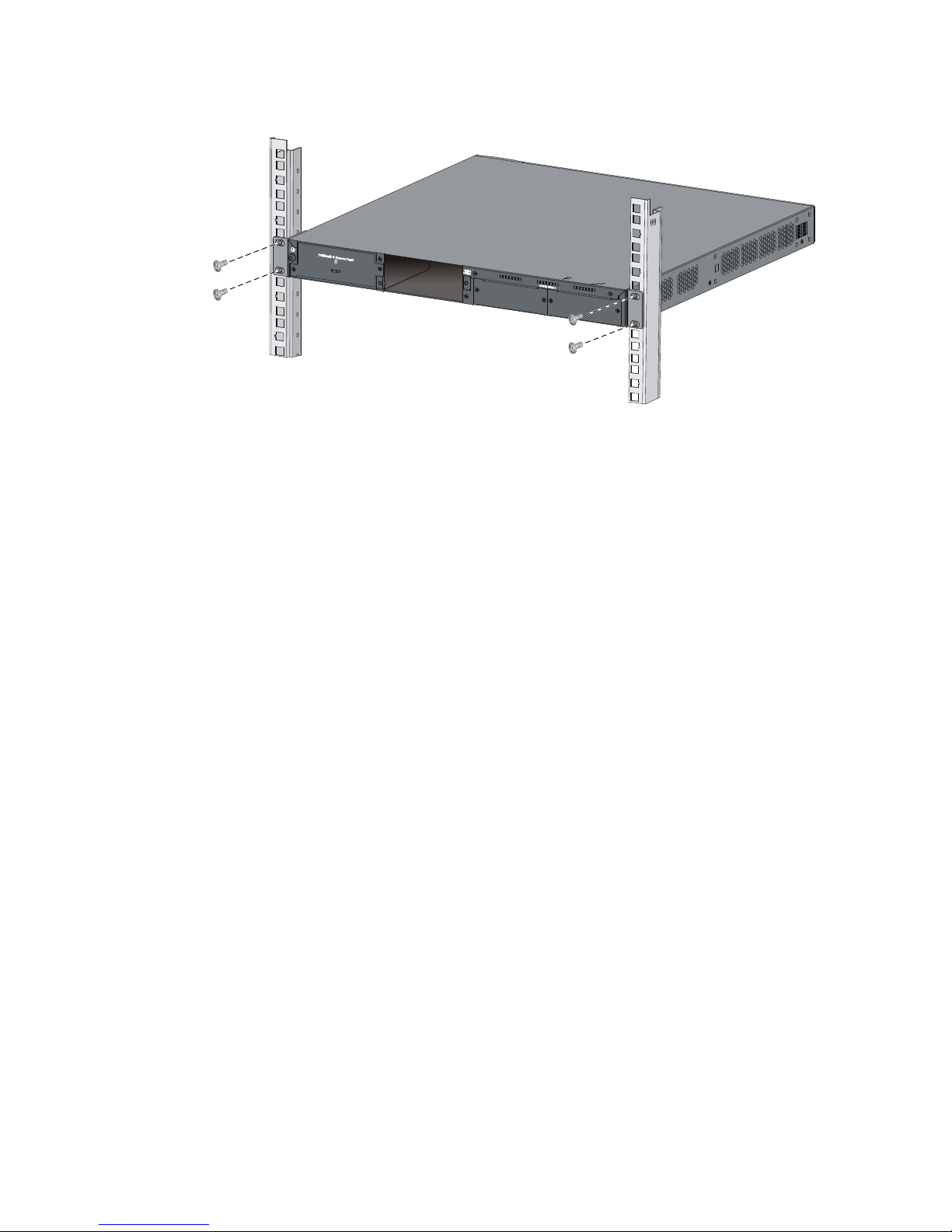
4. Install the fil
ler module over the empty power module slot to prevent dust and ensure good
ventilation if you install only one power module.
Figure 36 Installing the power module
Figure 37 PSR1110-56A in the chassis
Removing a PSR360-56A/PSR720-56A/PSR1110-56A power
module
1. Wear an ESD wrist strap and make sure it makes good skin contact and is well grounded.
2. Disconnect the power cord.
3. Press the latch towards the handle, and pull the power module along the guide rails until it is
part-way out.
Page 37

28
4. Grasp the handle of the power module with one hand, support the bottom with the other hand, and
pull the power module slowly along the guide rails out of the slot.
Put away the removed power module in an antistatic bag or the power module package bag for
future use.
5. Install the filler module to prevent dust and ensure good ventilation if no power module is installed
in the slot.
Figure 38 Removing the power module
The switch provides one filler module for the power module slot. To prevent dust and ensure good
ventilation, promptly install a filler module for an empty power module slot. To do so, slide the filler
module slowly along the guide rails into the slot until you hear that the latch of the filler module clicks into
the slot, as shown in Figure 39.
IMPORTANT:
W
hen you install a filler module, make sure the blade of the flathead screwdriver sign on the filler module
points upwards.
1
2
Page 38

29
Figure 39 Installing a filler module
If the power module slot where you want to install a power module is covered by a filler module, remove
the filler module first. To do so, insert a flathead screwdriver through the handle and pull the filler module
outward along the guide rails, as shown in Figure 40.
Put away the removed filler module for future use.
Figure 40 Removing a filler module
Connecting the power cord
CAUTION:
The AC power cord for the PSR150-A/PSR150-A1 uses C13 connector, while the AC power cord for the
PSR360-56A/PSR720-56A/PSR1110-56A uses high-temperature C15 connector. Do not mix them.
Page 39

30
Table 4 Power cord connection procedures at a glance
Power module Connection procedure reference
PSR150-A/PSR150-A1 Connecting the PSR150-A/PSR150-A1
PSR150-D/PSR150-D1 Connecting the PSR150-D/PSR150-D1
PSR360-56A/PSR720-56A/PSR1110-56A Connecting the PSR360-56A/PSR720-56A/PSR1110-56A
Connecting the PSR150-A/PSR150-A1
The following takes the PSR150-A as an example. The connection procedure for the PSR150-A1 is similar.
To connect the PSR150-A:
1. Wear an ESD wrist strap and make sure it makes good skin contact and is well grounded.
2. Attach the hooks of the bail latch (shipped with the power module) into the two holes next to the
power receptacle on the power module, and pull the bail latch leftwards (see Figure 41).
3. Connect one end of the AC power cord supplied with the power module to the power receptacle
(see callout 1 in Figure 42).
4. Pull th
e bail latch rightwards to secure the plug to the power receptacle (see callout 2 in Figure 42).
5. Connect the other end of the power cord to an AC power outlet.
Figure 41 Connecting the PSR150-A (1)
Figure 42 Connecting the PSR150-A (2)
Page 40

31
Connecting the PSR150-D/PSR150-D1
W
ARNING!
Identify the positive (+) and negative (-) marks on the two wires to avoid connection mistakes.
The following takes the PSR150-D as an example. The connection procedure for the PSR150-D1 is similar.
To connect the PSR150-D:
1. Wear an ESD wrist strap and make sure it makes good skin contact and is well grounded.
2. Unpack the DC power cord, correctly orient the plug at one end of the cable with the power
receptacle on the power module, and insert the plug into the power receptacle (see callout 1
in Figure 43).
T
he power receptacle is foolproof. If you cannot insert the plug into the receptacle, re-orient the
plug rather than use excessive force to push it in.
3. Tighten the screws on the plug with a flat-blade screwdriver to secure the plug in the power
receptacle (see callout 2 in Figure 43).
4. Conne
ct the two wires at the other end of the power cord to a –48 VDC power source.
NOTE:
You can also connect the PSR150-D to an H3C RPS800-A or RPS1600-A RPS, but you must purchase the
power cord separately.
Figure 43 Connecting the PSR150-D
Connecting the PSR360-56A/PSR720-56A/PSR1110-56A
The following takes the PSR720-56A as an example. The connection procedure for the PSR360-56A and
PSR1110 -56 A i s si mi l ar.
To connect the PSR720-56A:
1. Wear an ESD wrist strap and make sure it makes good skin contact and is well grounded.
2. Plug the female connector end of the AC power cord into the AC input socket of the power module
(see callout 1 in Figure 44).
Page 41

32
3. Use a cable tie to secure the power cord to the handle of the power module (see callout 2 and
callout 3 in Figure 44).
4. Connect the other end of the AC power cord to an AC power outlet.
Figure 44 Connecting the PSR720-56A
Installing/removing an interface card
This section uses the LSPM2SP2P interface card as an example to describe the procedures of installing
and removing an interface card.
For the interface cards available for the switch series, see "Interface cards."
Installing an interface card
IMPORTANT:
On the S5500-34C-HI, S5500-34F-HI, and S5500-34C-PWR-HI switches, you can install the LSP5GP8P0
and LSP5GT8P cards only in SLOT1.
To install an interface card:
1. Wear an ESD wrist strap and make sure it makes good skin contact and is well grounded.
2. Loosen the mounting screws on the filler panel over the interface card slot with a Phillips
screwdriver and remove the filler panel.
Put away the removed filler panel for future use.
Page 42

33
Figure 45 Removing the filler panel over an interface card slot
3. Hold the captive screws on the front panel of the interface card, and gently push the interface card
in along the slot guide rails until the interface card is in close contact with the switch chassis (see
callout 1 in Figure 46.)
4. T
ighten the captive screws with a Phillips screwdriver to secure the interface card in the slot (see
callout 2 in Figure 46).
Figure 46 Installing an interface card
Figure 47 LSP5GT8P in the chassis
Page 43

34
NOTE:
The LSP5GT8P interface card adds 34.75 mm (1.37 in) to the depth of the S5500-HI switch.
Figure 48 LSP5GP8P0 in the chassis
NOTE:
The LSP5GP8P0 interface card adds 69.75 mm (2.75 in) to the depth of the S5500-HI switch.
Removing an interface card
CAUTION:
• Do not touch the surface-mounted components directly with your hands.
• If no new card is to be installed, install the filler panel to prevent dust and ensure
g
ood ventilation in the
switch.
To remove an interface card:
1. Wear an ESD wrist strap and make sure it makes good skin contact and is well grounded.
2. Use a Phillips screwdriver to completely loosen the captive screws at both sides of the interface
card.
3. Gently pull the interface card along the guide rails until it completely comes out of the switch
chassis.
Installing/removing a CX4/SFP+ cable
This section assumes that you have installed a CX4/SFP+ interface card.
The installation and removal procedures for the CX4 cable and the SFP+ cable are the same. This section
uses the SFP+ cable as an example.
The CX4 and SFP+ cables for this switch series are hot swappable.
Installing a CX4/SFP+ cable
CAUTION:
The bend radius for a cable must be at least eight times the cable diameter.
To connect a CX4 or SFP+ cable to a port on a CX4/SFP+ interface card:
Page 44

35
1. Wear an ESD wrist strap and make sure it makes good skin contact and is well grounded. Then
unpack the dedicated SFP+ cable.
2. Hold the connector at one end of the cable, with the pull latch on top.
3. Orient the connector with the port and insert it into the port.
Removing a CX4/SFP+ cable
1. Wear an ESD wrist strap and make sure it makes good skin contact and is well grounded.
2. Hold the cable connector and pull the pull latch of the connector to remove the cable from the
switch.
Verifying the installation
After you complete the installation, verify that:
• There is enough space for heat dissipation around the switch, and the rack or workbench is stable.
• The grounding cable is securely connected.
• The correct power source is used.
• The power cords are correctly connected.
• All the interface cables are cabled indoors. If any cable is routed outdoors, verify that the socket
strip with lightning protection has been correctly connected.
Page 45

36
Accessing the switch for the first time
Setting up the configuration environment
The first time you access the switch you must use a console cable to connect a console terminal, for
example, a PC, to the console port on the switch.
Figure 49 Connecting the console port to a terminal
Connecting the console cable
Console cable
A console cable is an 8-core shielded cable, with a crimped RJ-45 connector at one end for connecting
to the console port of the switch, and a DB-9 female connector at the other end for connecting to the
serial port on the console terminal.
Figure 50 Console cable
Connection procedure
To connect a terminal (for example, a PC) to the switch:
Main label
1
8
B side
B
Pos.9
Pos.1
A side
A
Page 46

37
1. Plug the DB-9 female connector of the console cable to the serial port of the PC.
2. Connect the RJ-45 connector to the console port of the switch.
NOTE:
• Identify the mark on the console port and make sure you are connecting to the correct port.
• The serial ports on PCs do not support hot swapping. If the switch has been powered on, connect the
console cable to the PC before connecting to the switch, and when you disconnect the cable, first
disconnect from the switch.
Setting terminal parameters
To configure and manage the switch, you must run a terminal emulator program on the console terminal.
The following are the required terminal settings:
• Bits per second—9,600
• Data bits—8
• Parity—None
• Stop bits—1
• Flow control—None
• Emulation—VT100
To set terminal parameters, for example, on a Windows XP HyperTerminal:
1. Select Start > All Programs > Accessories > Communications > HyperTerminal.
The Connection Description dialog box appears.
2. Enter the name of the new connection in the Name field and click OK.
Figure 51 Connection description
3. Select the serial port to be used from the Connect using list, and click OK.
Page 47

38
Figure 52 Setting the serial port used by the HyperTerminal connection
4. Set Bits per second to 9600, Data bits to 8, Parity to None, Stop bits to 1, and Flow control to None,
and click OK.
Figure 53 Setting the serial port parameters
5. Select File > Properties in the HyperTerminal window.
Page 48

39
Figure 54 HyperTerminal window
6. On the Settings tab, set the emulation to VT100 and click OK.
Figure 55 Setting terminal emulation in Switch Properties dialog box
Page 49

40
Powering on the switch
Before powering on the switch, verify that the following conditions are met:
• The power cord is correctly connected.
• The input power voltage meets the requirement of the switch.
• The console cable is correctly connected, the terminal or PC used for configuration has started, and
the configuration parameters have been set.
Power on the switch. During the startup process, you can access Boot ROM menus to perform tasks such
as software upgrade and file management. The Boot ROM interface and menu options differ with
software versions. For more information about Boot ROM menu options, see the software-matching
release notes for the device.
After the startup completes, you can access the CLI to configure the switch.
NOTE:
For more information about the configuration commands and CLI, see
H3C S5500-HI Switch Series
Configuration Guides
and
H3C S5500-HI Switch Series Command References
.
Page 50

41
Setting up an IRF fabric
You can use H3C Intelligent Resilient Framework (IRF) technology to connect and virtualize S5500-HI
switches into a virtual switch called an "IRF fabric" or "IRF virtual device" for flattened network topology,
and high availability, scalability, and manageability.
Table 5 Model matrix for forming an IRF fabric
Model
S5500-34
C-HI
S5500-52
SC-HI
S5500-34
F-HI
S5500-34
C-PWR-HI
S5500-58
C-PWR-HI
S5500-28
SC-HI
S5500-5
2SC-HI
S5500-34
C-HI
Yes Yes Yes Yes Yes No No
S5500-58
C-HI
Yes Yes Yes Yes Yes No No
S5500-34
F-HI
Yes Yes Yes Yes Yes No No
S5500-34
C-PWR-HI
Yes Yes Yes Yes Yes No No
S5500-58
C-PWR-HI
Yes Yes Yes Yes Yes No No
S5500-28
SC-HI
No No No No No Yes Yes
S5500-52
SC-HI
No No No No No Yes Yes
IMPORTANT:
To set up IRF connection between S5500-HI switches, you must use 10-Gigabit ports.
Page 51

42
IRF fabric setup flowchart
Figure 56 IRF fabric setup flowchart
To set up an IRF fabric:
Step Description
1. Plan IRF fabric setup
Plan the installation site and IRF fabric setup parameters:
• Planning IRF fabric size and the installation site
• Identifying the master switch and planning IRF member IDs
• Planning IRF topology and connections
• Identifying physical IRF ports on the member switches
• Planning the cabling scheme
2. Install IRF member switches
See "Installing the switch in a 19-inch rack"or "Mounting the switch
on a workbenc
h."
3. Install the grounding cable, fan
tray, power modules, and power
cords
See "Grounding the switch," "Installing/removing a fan tray,"
"Installing/removing a power module," and "Connecting the power
cord."
Page 52

43
Step Description
4. Power on the switches
N/A
5. (Optional) Install an expansion
interface card
See "Installing/removing an interface card."
6. Configure basic IRF settings
See H3C S5500-HI Switch Series IRF Configuration Guide.
7. Connect the physical IRF ports
Connect the physical IRF ports on the switches.
Select appropriate cables according to physical IRF port types.
All switches except the master switch automatically reboot, and the
IRF fabric is established.
Planning IRF fabric setup
This section describes issues that an IRF fabric setup plan must cover.
Planning IRF fabric size and the installation site
Identify the number of required IRF member switches, depending on the user density and upstream
bandwidth requirements. The switching capacity of an IRF fabric equals the total switching capacities of
all member switches.
Plan the installation site depending on your network solution, as follows:
• Place all IRF member switches in one rack for centralized high-density access.
• Distribute the IRF member switches in different racks for dispersed access.
NOTE:
A
n S5500-HI IRF fabric can have up to nine switches. As your business grows, you can plug an S5500-HI
switch into an IRF fabric to increase the switching capacity without any topology change or replacement.
Identifying the master switch and planning IRF member IDs
Determine which switch you want to us e as the master for manag ing all member switches in the IRF fa bric.
An IRF fabric has only one master switch. You configure and manage all member switches in the IRF
fabric at the command line interface of the master switch.
NOTE:
IRF member switches will automatically elect a master. You can affect the election result by assigning a
high member priority to the intended master switch. For more information about master election, see
H3
C
S5500-HI Switch Series IRF Configuration Guide
.
Prepare an IRF member ID assignment scheme. An IRF fabric uses member IDs to uniquely identify and
manage its members, and you must assign each IRF member switch a unique member ID.
Page 53

44
Planning IRF topology and connections
You can create an IRF fabric in daisy chain topology, or more reliably, ring topology. In ring topology,
the failure of one IRF link does not cause the IRF fabric to split as in daisy chain topology. Rather, the IRF
fabric changes to a daisy chain topology without interrupting network services.
You connect the IRF member switches through IRF ports, the logical interfaces for the connections
between IRF member switches. Each IRF member switch has two IRF ports: IRF-port 1 and IRF-port 2. To
use an IRF port, you must bind at least one physical port to it.
When connecting two neighboring IRF member switches, you must connect the physical ports of IRF-port
1 on one switch to the physical ports of IRF-port 2 on the other switch.
The S5500-HI switches can provide 10-GE IRF connections through the SFP+ ports on the front panel and
the 10G interface card at the rear of the chassis, and you can bind several 10G ports to an IRF port for
increased bandwidth and availability.
NOTE:
• Figure 57 and
Figure 58 show the topologies for an IRF fabric made up of three S5500-34C-HI
switches that have two 2-port 10 GE SFP+ interface cards for IRF connections.
• The IRF port connections in the two fi
g
ures are for illustration only, and more connection methods are
available.
• For information about the physical ports available for IRF connections on different S5500-HI switches,
see Table 6.
Figure 57 IRF fabric in daisy chain topology
Page 54

45
Figure 58 IRF fabric in ring topology
Identifying physical IRF ports on the member switches
Identify the physical IRF ports on the member switches according to your topology and connection
scheme.
To set up IRF connection, you can use the two SFP+ ports on the front panel and the 10-Gigabit ports on
the expansion interface card. For more information about interface cards, see "Appendix B FRUs and
co
mpatibility matrixes."
Table 6 shows the physical ports that can be used for IRF connection for different switch models.
Table 6 Physical IRF port requirements for different switch models
Switch model Requirements
S5500-34C-HI
S5500-34F-HI
S5500-34C-PWR-HI
S5500-28SC-HI
The two SFP+ ports on the front panel and 10-Gigabit ports on the expansion
interface card can be bound to any IRF port.
S5500-58C-HI
S5500-58C-PWR-HI
• Physical ports on the same interface card can only be bound to the same IRF
port.
• SFP+ port numbered 53 on the front panel can only be bound to th e s a m e IRF
port as physical ports on the interface card in slot 2.
• SFP+ por t numb e red 54 on the fro n t panel can only b e bound to the same I R F
port as physical ports on the interface card in slot 1.
S5500-52SC-HI
• The SFP+ ports (numbered 51 and 52) on the front panel must be bound to
different IRF ports. For example, if you bind SFP+ port 51 to IRF port 1, you
must bind SFP+ port 52 to IRF port 2.
• If a two-port interface card is used, you can bind port 1 on the card and SFP+
port 51 into one aggregate IRF link, and port 2 on the card and SFP+ port 52
into the other aggregate IRF link.
• If a one-port interface card is used, you can bind the port on the card and
SFP+ port 51 into one aggregate IRF link.
Page 55

46
Planning the cabling scheme
Select appropriate cables to connect physical IRF ports:
• Use XFP transceiver modules and fibers to connect XFP ports.
• Use SFP+ transceiver modules and fibers to connect SFP+ ports over a long distance, and use SFP+
cables over a short distance.
• Use CX4 cables to connect CX4 ports.
• Use category 6 or above twisted pair cables to connect 1/10GBase-T Ethernet ports.
If the IRF member switches are far away from one another, choose the SFP+/XFP transceiver modules
with optical fibers. If the IRF member switches are all in one equipment room, choose CX4/SFP+ cables
or twisted pair cables.
For the transceiver modules and cables available for IRF connections, see "10 Gbps SFP+ transceiver
modu
les/SFP+ cables," "10 Gbps XFP transceiver modules," and "CX4 cables".
The following subsections describe several H3C recommended IRF connection schemes, and all these
schemes use a ring topology.
IMPORTANT:
In these schemes, all physical IRF ports are located on the same side. If physical IRF ports are on differen
t
sides, you must measure the distance between them to select an appropriate cable.
Connecting the IRF member switches in one rack
Use CX4/SFP+ cables or twisted pair cables to connect the IRF member switches (nine switches in this
example) in a rack as shown in Figure 59. T
he switches in the ring topology (see Figure 60) are in the
same order as connected in the rack.
Page 56

47
Figure 59 Connecting the switches in the same rack
Figure 60 IRF fabric topology
Page 57

48
Connecting the IRF member switches in a ToR solution
You can install IRF member switches in different racks side by side to deploy a top of rack (ToR)
solution. Figure 61
shows an example for connecting nine top of rack IRF member switches by using SFP+
transceiver modules and optical fibers. The topology is the same as Figure 60.
Figure 61 Connecting top of rack switches
Configuring basic IRF settings
After you install the IRF member switches, power on the switches, and log in to each IRF member switch
(see H3C S5500-HI Switch Series Fundamentals Configuration Guide) to configure their member IDs,
member priorities, and IRF port bindings.
Follow these guidelines when you configure the switches:
• Assign the master switch higher member priority than any other switch.
• Bind physical ports to IRF port 1 on one switch and to IRF port 2 on the other switch.
• To bind the ports on an interface card to an IRF port, you must install the interface card first. For how
to install an interface card, see "Installing/removing an inter
face card."
• Execute the display irf configuration command to verify the basic IRF settings.
For more information about configuring basic IRF settings, see H3C S5500-HI Switch Series IRF
Configuration Guide.
Connecting the physical IRF ports
Use correct cables to connect the IRF member switches as planned.
NOTE:
W
ear an ESD wrist strap when you connect CX4/SFP+ cables or SFP+/XFP transceiver modules and
fibers. For how to connect them, see
H3C Pluggable SFP/SFP+/XFP Transceiver Modules Installation
Guide
and "Installing/removing a CX4/SFP+ cable."
Accessing the IRF fabric to verify the configuration
To verify the basic functionality of the IRF fabric after you finish configuring basic IRF settings and
connecting IRF ports:
1. Log in to the IRF fabric through the console port of any member switch.
2. Create a Layer 3 interface, assign it an IP address, and make sure the IRF fabric and the remote
network management station can reach each other.
Page 58

49
3. Use Telnet, web, or SNMP to access the IRF fabric from the network management station. (See
H3C S5500-HI Switch Series Fundamentals Configuration Guide.)
4. Verify that you can manage all member switches as if they were one node.
5. Display the running status of the IRF fabric by using the commands in Table 7.
Table 7 Displaying and maintaining IRF configuration and runni
ng status
To do… Use the command…
Display information about the IRF fabric display irf
Display all members’ configurations that take effect
after switch reboots
display irf configuration
Display topology information about the IRF fabric display irf topology
NOTE:
To avoid IP address collision and network problems, configure at least one multi-active detection (MAD)
mechanism to detect the presence of multiple identical IRF fabrics and handle collisions. For more
information about MAD detection, see
H3C S5500-HI Switch Series IRF Configuration Guide
.
Page 59

50
Maintenance and troubleshooting
Power module failure
Look at the PWR1 or PWR2 LED of the switch to identify a power module failure. For more information
about the PWR1 and PWR2 LEDs on the front panel of the switch, see "Appendix C Ports and LEDs."
If the po
wer module system is correctly operating, the power module status LEDs are steady green. If the
LEDs behave in any other way, verify the following items:
• The switch power cord is correctly connected.
• The power source meets the requirement.
• The operating temperature of the switch is in the normal range and the power module has good
ventilation.
NOTE:
If the problem persists, contact H3C for help.
To replace a hot swappable power module, see "Installing/removing a power module."
Fan failure
CAUTION:
For the S5500-28SC-HI and S5500-52SC-HI switches, you can replace the fan tray without powerin
g
off
the switch. To prevent overheating, replace the failed fan tray within 2 minutes.
You can look at the system status LED and the seven-segment LED of an S5500 -HI switch to identify a fan
failure. If both LEDs are behaving as described in Table 8, a f
an failure occurs.
Table 8 LED behaviors that identify a fan failure
LED Mark State
System status LED SYS Steady red
Seven-segment LED Unit
The LED displays a flashing F character.
The S5500-34C-HI, S5500-34F-HI, S5500-34C-PWR-HI, S5500-58C-HI, and S5500-58C-PWR-HI
switches use built-in fan trays. If a fan failure occurs, promptly contact H3C for help.
The S5500-28SC-HI and S5500-52SC-HI switches use hot swappable fan trays. When the fan tray fails,
use the display fan command to verify that the expected airflow direction is the same as the airflow
direction of the fan tray. If not, use the fan prefer-direction command to modify the configuration.
If the problem still exists, the fan tray might have failed. You can replace the fan tray as described in
"Installing/removing a fan tray."
Page 60

51
Configuration terminal problems
If the configuration environment setup is correct, the configuration terminal displays booting information
when the switch is powered on. If the setup is incorrect, the configuration terminal displays nothing or
garbled text.
No terminal display
If the configuration terminal displays nothing when the switch is powered on, verify the following items:
• The power module is supplying power to the switch.
• The console cable is correctly connected.
• The console cable has no problem and the terminal settings are correct.
Garbled terminal display
If terminal display is garbled, verify that the following settings are configured for the terminal, for
example, HyperTerminal:
• Baud rate—9,600
• Data bits—8
• Parity—none
• Stop bits—1
• Flow control—none
• Emulation—VT100
Page 61

52
Appendix A Chassis views and technical
specifications
Chassis views
S5500-34C-HI
Figure 62 S5500-34C-HI front panel
(1) 10/100/1000 Base-T auto-sensing Ethernet port (2) 10/100/1000 Base-T Ethernet port LED
(3) SFP port LED (4) SFP+ port LED
(5) Management Ethernet port LED (ACT/LINK)
(6) Seven-segment LED (Unit)
(7) Port mode LED (Mode) (8) System status LED (SYS)
(9) Power module 1 status LED (PWR1)
(10) Power module 2 status LED (PWR2)
(11) Interface card 1 status LED (SLOT1)
(12) Interface card 2 status LED (SLOT2)
(13) Port LED mode switching button (14) Console port
(15) Management Ethernet port (Management)
(16) SFP+ port
(17) 100/1000Base-X SFP port
Figure 63 S5500-34C-HI rear panel
(1) Grounding screw (2) Power module slot 1 (PWR1)
(3) Power module slot 2 (PWR2) (4) Interface card slot 1 (SLOT1)
(5) Interface card slot 2 (SLOT2)
1 2
3
4
5
6
7
8
9
10
11
12
13
14
15
16
17
Page 62

53
NOTE:
• The S5500-34C-HI switch comes with two expansion interface card slots covered by filler panels.
• The S5500-34C-HI switch comes with power module slot 1 covered by a filler panel and power module
slot 2 empty. In this figure, a PSR150-A power module is installed in power module slot 2.
S5500-58C-HI
Figure 64 S5500-58C-HI front panel
(1) 10/100/1000 Base-T auto-sensing Ethernet port (2) 10/100/1000 Base-T Ethernet port LED
(3) SFP port LED (4) 100/1000Base-X SFP port
(5) Management Ethernet port (Management)
(6) Console port
(7) Seven-segment LED (Unit) (8) Port LED mode switching button
(9) Port mode LED (Mode) (10) Power module 1 status LED (PWR1)
(11) Power module 2 status LED (PWR2)
(12) System status LED (SYS)
(13) Interface card 2 status LED (SLOT2) (14) Interface card 1 status LED (SLOT1)
(15) Management Ethernet port LED (ACT/LINK)
(16) SFP+ port
(17) SFP+ port LED
Figure 65 S5500-58C-HI rear panel
(1) Grounding screw (2) Power module slot 1 (PWR1)
(3) Power module slot 2 (PWR2) (4) Interface card slot 1 (SLOT1)
(5) Interface card slot 2 (SLOT2)
Page 63

54
NOTE:
• The S5500-58C-HI switch comes with two expansion interface card slots covered by filler panels.
• The S5500-58C-HI switch comes with power module slot 1 covered by a filler panel and power module
slot 2 empty. In this figure, a PSR150-A power module is installed in power module slot 2.
S5500-34F-HI
Figure 66 S5500-34F-HI front panel
(1) 100/1000 Base-X SFP port (2) SFP port LED
(3) 10/100/1000 Base-T Ethernet port LED
(4) SFP+ port LED
(5) Management Ethernet port LED (ACT/LINK)
(6) Seven-segment LED (Unit)
(7) Port mode LED (Mode) (8) System status LED (SYS)
(9) Power module 1 status LED (PWR1)
(10) Power module 2 status LED (PWR2)
(11) Interface card 1 status LED (SLOT1)
(12) Interface card 2 status LED (SLOT2)
(13) Port LED mode switching button (14) Console port
(15) Management Ethernet port (Management)
(16) SFP+ port
(17) 10/100/1000 Base-T auto-sensing Ethernet port
Figure 67 S5500-34F-HI rear panel
(1) Grounding screw (2) Power module slot 1 (PWR1)
(3) Power module slot 2 (PWR2) (4) Interface card slot 1 (SLOT1)
(5) Interface card slot 2 (SLOT2)
Page 64

55
NOTE:
• The S5500-34F-HI switch comes with two expansion interface card slots covered by filler panels.
• The S5500-34F-HI switch comes with power module slot 1 covered by a filler panel and power module
slot 2 empty. In this figure, a PSR150-A power module is installed in power module slot 2.
S5500-34C-PWR-HI
Figure 68 S5500-34C-PWR-HI front panel
(1) 10/100/1000 Base-T auto-sensing Ethernet port (2) 10/100/1000 Base-T Ethernet port LED
(3) SFP port LED (4) SFP+ port LED
(5) Management Ethernet port LED (ACT/LINK)
(6) Seven-segment LED (Unit)
(7) Port mode LED (Mode) (8) System status LED (SYS)
(9) Power module 1 status LED (PWR1)
(10) Power module 2 status LED (PWR2)
(11) Interface card 1 status LED (SLOT1)
(12) Interface card 2 status LED (SLOT2)
(13) Port LED mode switching button (14) Console port
(15) Management Ethernet port (Management)
(16) SFP+ port
(17) 100/1000 Base-X SFP port
Figure 69 S5500-34C-PWR-HI rear panel
(1) Grounding screw (2) Interface card slot 1 (SLOT1)
(3) Interface card slot 2 (SLOT2) (4) Power module slot 1 (PWR1)
(5) Power module slot 2 (PWR2)
Page 65

56
NOTE:
• The S5500-34C-PWR-HI switch comes with two expansion interface card slots covered by filler panels.
• The S5500-34C-PWR-HI switch comes with power module slots empty.
S5500-58C-PWR-HI
Figure 70 S5500-58C-PWR-HI front panel
(1) 10/100/1000 Base-T auto-sensing Ethernet port (2) 10/100/1000 Base-T Ethernet port LED
(3) SFP port LED (4) 100/1000 Base-X SFP port
(5) Management Ethernet port (Management)
(6) Console port
(7) Seven-segment LED (Unit) (8) Port LED mode switching button
(9) Port mode LED (Mode) (10) Power module 1 status LED (PWR1)
(11) Power module 2 status LED (PWR2)
(12) System status LED (SYS)
(13) Interface card 2 status LED (SLOT2) (14) Interface card 1 status LED (SLOT1)
(15) Management Ethernet port LED (ACT/LINK)
(16) SFP+ port
(17) SFP+ port LED
Figure 71 S5500-58C-PWR-HI rear panel
(1) Grounding screw (2) Interface card slot 1 (SLOT1)
(3) Interface card slot 2 (SLOT2) (4) Power module slot 1 (PWR1)
(5) Power module slot 2 (PWR2)
NOTE:
• The S5500-58C-PWR-HI switch comes with two expansion interface card slots covered by filler panels.
• The S5500-58C-PWR-HI switch comes with power module slots empty.
Page 66

57
S5500-28SC-HI
Figure 72 S5500-28SC-HI front panel
(1) 10/100/1000Base-T auto-sensing Ethernet port (2) 10/100/1000Base-T Ethernet port LED
(3) ACT LED for the management Ethernet port
(4) Management Ethernet port
(5) LINK LED for the management Ethernet port
(6) Console port
(7) Seven-segment LED (Unit) (8) Port LED mode switching button
(9) System status LED (SYS) (10) SFP+ port
(11) Port mode LED (MODE) (12) Interface card status LED (SLOT)
(13) SFP+ port LED (14) Power module 2 status LED (PWR2)
(15) 1000Base-X SFP port LED (16) Power module 1 status LED (PWR1)
(17) 1000Base-X SFP port
Figure 73 S5500-28SC-HI rear panel
(1) Grounding screw in the rear grounding point
(2) Power module slot 1
(3) Fan tray slot (4) Expansion interface card slot
(5) Power module slot 2
Page 67

58
NOTE:
• The S5500-28SC-HI switch comes with an expansion interface card slot covered by a filler panel.
• The S5500-28SC-HI switch comes with power module slots empty. You can install one or two power
modules for the switch as needed. In Figure 73, a P
SR150-A power module is installed in power module
slot 1.
• The S5500-28SC-HI switch also comes with the fan tray slot empty. You must install a fan tray for the
switch and make sure the ventilation direction of the fan tray is suitable at the installation site. In Fi
g
ure
73, an LSPM1FAN fan tray is installed.
Figure 74 S5500-28SC-HI left side panel
(1) Side grounding point
S5500-52SC-HI
Figure 75 S5500-52SC-HI front panel
(1) 10/100/1000Base-T auto-sensing Ethernet port (2) 10/100/1000Base-T Ethernet port LED
(3) ACT LED for the management Ethernet port (4) Management Ethernet port
(5) LINK LED for the management Ethernet port
(6) Console port
(7) Seven-segment LED (Unit) (8) Port LED mode switching button
(9) System status LED (SYS) (10) SFP+ port
(11) Port mode LED (MODE) (12) Interface card status LED (SLOT)
(13) SFP+ port LED
(14) Power module 2 status LED (PWR2)
(15) 1000Base-X SFP port LED (16) Power module 1 status LED (PWR1)
Page 68

59
(17) 1000Base-X SFP port
Figure 76 S5500-52SC-HI rear panel
(1) Grounding screw in the rear grounding point
(2) Power module slot 1
(3) Fan tray slot (4) Expansion interface card slot
(5) Power module slot 2
NOTE:
• The S5500-52SC-HI switch comes with an expansion interface card slot covered by a filler panel.
• The S5500-52SC-HI switch comes with power module slots empty. You can install one or two power
modules for the switch as needed. In Figure 76, a
PSR150-A power module is installed in power module
slot 1.
• The S5500-52SC-HI switch also comes with the fan tray slot empty. You must install a fan tray for the
switch and make sure the ventilation direction of the fan tray is suitable at the installation site. In Fi
g
ure
76, an LSPM1FAN fan tray is installed.
Figure 77 S5500-52SC-HI left side panel
(1) Side grounding point
Technical specifications
Table 9 H3C S5500-34C-HI&S5500-58C-HI&S5500-34F-HI switches technical specifications
Item S5500-34C-HI S5500-58C-HI S5500-34F-HI
Dimensions (H × W
× D)
43.6 × 440 × 360 mm
(1.72 × 17.32 × 14.17 in)
43.6 × 440 × 420 mm
(1.72 × 17.32 × 16.54 in)
43.6 × 440 × 360 mm
(1.72 × 17.32 × 14.17 in)
Weight < 7.5 kg (16.53 lb) < 8.5 kg (18.74 lb) < 7.5 kg (16.53 lb)
Management ports 1 console port, 1 management Ethernet port, both on the front panel
Page 69

60
Item S5500-34C-HI S5500-58C-HI S5500-34F-HI
Fixed network ports
(on the front panel)
• 24 ×
10/100/1000Base-T
auto-sensing Ethernet
ports
• 4 × 100/1000Base-X
SFP ports
• 2 × 1/10 Gbps SFP+
ports
• 48
×10/100/1000Base-T
auto-sensing Ethernet
ports
• 4 × 100/1000Base-X
SFP ports
• 2 x 1/10 Gbps SFP+
ports
• 24 × 100/1000Base-X
SFP ports
• 4 ×
10/100/1000Base-T
auto-sensing Ethernet
ports
• 2 × 1/10 Gbps SFP+
ports
Expansion interface
card slots
2 (SLOT1 and SLOT2), on
the rear panel
2 (SLOT1 and SLOT2), on
the rear panel
2 (SLOT1 and SLOT2), on
the rear panel
Power module slots 2, on the rear panel 2, on the rear panel 2, on the rear panel
Input voltage
• AC-input
{ Rated voltage range: 100 VAC to 240 VAC @ 50 Hz or 60 Hz
{ Max voltage range: 90 VAC to 264 VAC @ 47 Hz to 63 Hz
• DC-input
{ Rated voltage range: –48 VDC to –60 VDC
{ Max voltage range: –36 VDC to –72 VDC
NOTE:
You can use the site –48 VDC power supply or an H3C RPS800-A or RPS1600-A RPS as
the DC power source.
Minimum power
consumption
AC: 62 W
DC: 55.5 W
AC: 94 W
DC: 86.4 W
AC: 60 W
DC: 50 W
Maximum power
consumption
AC: 141 W
DC: 115 W
AC: 191 W
DC: 180 W
AC: 135 W
DC: 115 W
Chassis leakage
current compliance
UL60950-1, EN60950-1, IEC60950-1, GB4943
Melting current of
power module fuse
• AC-input: 3.15 A, 250V
• DC-input: 8 A, 250V
Operating
temperature
0°C to 50°C (32°F to 122°F) or 0°C to 45°C (32°F to 113°F) when the
XFP-LH40-SM1550-F1 or XFP-LH80-SM1550 is used
Relative humidity 5% to 95%, noncondensing
Fire resistance
compliance
UL60950-1, EN60950-1, IEC60950-1, GB4943
Table 10 H3C S5500-34C-PWR-HI&S5500-58C-PWR-HI switches technical specifications
Item S5500-34C-PWR-HI S5500-58C-PWR-HI
Dimensions (H × W
× D)
43.6 × 440 × 460 mm
(1.72 × 17.32 × 18.11 in)
43.6 × 440 × 460 mm
(1.72 × 17.32 × 18.11 in)
Weight < 10 kg (22.05 lb) < 10.5 kg (23.15 lb)
Management ports 1 console port, 1 management Ethernet port, both on the front panel
Page 70

61
Item S5500-34C-PWR-HI S5500-58C-PWR-HI
Fixed network ports
(on the front panel)
• 24 × 10/100/1000Base-T
auto-sensing Ethernet ports
• 4 × 100/1000Base-X SFP ports
• 2 × 1/10 Gbps SFP+ ports
• 48 ×10/100/1000Base-T auto-sensing
Ethernet ports
• 4 × 100/1000Base-X SFP ports
• 2 x 1/10 Gbps SFP+ ports
Expansion interface
card slots
2 (SLOT1 and SLOT2), on the rear
panel
2 (SLOT1 and SLOT2), on the rear panel
Power module slots 2, on the rear panel 2, on the rear panel
Input voltage
• PSR360-56A/PSR720-56A AC-input
{ Rated voltage range: 100 VAC to 240 VAC @ 50 Hz or 60 Hz
{ Max voltage range: 90 VAC to 264 VAC @ 47 Hz to 63 Hz
• P S R 1110 - 5 6 A A C - i n p u t
{ Rated voltage range: 115 VAC to 240 VAC @ 50 Hz or 60 Hz
{ Max voltage range: 102.5 VAC to 264 VAC @ 47 Hz to 63 Hz
PoE power capacity
Depends on the power module configurations. For more information, see the following
table.
Minimum power
consumption
80 W 115 W
Maximum power
consumption
(including PoE
power consumption)
950 W 1840 W
Chassis leakage
current compliance
UL60950-1, EN60950-1, IEC60950-1, GB4943
Melting current of
power module fuse
15 A, 250V
Operating
temperature
0°C to 45°C (32°F to 113°F)
Relative humidity 5% to 95%, noncondensing
Fire resistance
compliance
UL60950-1, EN60950-1, IEC60950-1, GB4943
The following table describes S5500-34C-PWR-HI&S5500-58C-PWR-HI switches PoE power capacity:
Power module
configuration
S5500-34C-PWR-HI S5500-58C-PWR-HI
Total PoE
power capacity
Max PoE power
capacity per port
Total PoE power
capacity
Max PoE power
capacity per port
Two PSR1110-56A 720 W 30 W 1440 W 30 W
One PSR1110-56A
and one
PSR720-56A
720 W 30 W 1440 W 30 W
One PSR1110-56A
and one
PSR360-56A
720 W 30 W 1100 W 30 W
Page 71

62
Power module
configuration
S5500-34C-PWR-HI S5500-58C-PWR-HI
Total PoE
power capacity
Max PoE power
capacity per port
Total PoE power
capacity
Max PoE power
capacity per port
Two PSR720-56A 720 W 30 W 1100 W 30 W
One PSR1110-56A 720 W 30 W 800 W 30 W
One PSR720-56A
and one
PSR360-56A
720 W 30 W 800 W 30 W
One PSR720-56A 450 W 30 W 450 W 30 W
Two PSR360-56A 450 W 30 W 450 W 30 W
One PSR360-56A 160 W 30 W 160 W 30 W
Table 11 H3C S5500-28SC-HI&S5500-52SC-HI switches technical specifications
Item S5500-28SC- HI S5500-52SC- HI
Dimensions (H × W
× D)
43.6 × 440 × 420 mm (1.72 × 17.32
× 16.54 in)
43.6 × 440 × 420 mm (1.72 × 17.32 ×
16.54 in)
Weight < 7.7 kg (16.98 lb) < 8.2 kg (18.08 lb)
Management ports 1 console port, 1 management Ethernet port, both on the front panel
Fixed network ports
(on the front panel)
• 24 × 10/100/1000Base-T
auto-sensing Ethernet ports
• 2 × 1000Base-X SFP ports, combo
interfaces
• 2 × 1/10 Gbps SFP+ ports
• 48 ×10/100/1000Base-T auto-sensing
Ethernet ports
• 2 × 1000Base-X SFP ports, combo
interfaces
• 2 x 1/10 Gbps SFP+ ports
Expansion interface
card slots
1, on the rear panel 1, on the rear panel
Fan tray slots 1, on the rear panel 1, on the rear panel
Power module slots 2, on the rear panel 2, on the rear panel
Input voltage
• AC-input
{ Rated voltage range: 100 VAC to 240 VAC @ 50 Hz or 60 Hz
{ Max voltage range: 90 VAC to 264 VAC @ 47 Hz to 63 Hz
• DC-input
{ Rated voltage range: –48 VDC to –60 VDC
{ Max voltage range: –36 VDC to –72 VDC
NOTE:
You can use the site –48 VDC power supply or an H3C RPS800-A or RPS1600-A RPS as
the DC power source.
Minimum power
consumption
AC: 48.2 W
DC: 51.1 W
AC: 68 W
DC: 57.6 W
Maximum power
consumption
AC: 107 W
DC: 85 W
AC: 145 W
DC: 126 W
Page 72

63
Item S5500-28SC- HI S5500-52SC- HI
Hot swappable fan
tray maximum
power consumption
LSPM1FAN: 19.5 W
LSPM1FANB: 19.5 W
Chassis leakage
current compliance
UL60950-1, EN60950-1, IEC60950-1, GB4943
Melting current of
power module fuse
AC-input: 3.15A/250V
DC-input: 8A/250V
Operating
temperature
0°C to 50°C (32°F to 122°F) or 0°C to 45°C (32°F to 113°F) when the
XFP-LH40-SM1550-F1 or XFP-LH80-SM1550 is used
Relative humidity 5% to 95%, noncondensing
Fire resistance
compliance
UL60950-1, EN60950-1, IEC60950-1, GB4943
Cooling system
The cooling system of the S5500-HI switch comprises the air vents in the chassis, built-in fans, and built-in
fans of power modules. To guarantee the performance of this cooling system, you must consider the
ventilation design for the installation site when you plan the installation site for the S5500-HI switch.
Cooling system of the S5500-28SC-HI and S5500-52SC-HI
The fan trays available for the S5500-28SC-HI and S5500-52SC-HI switches include LSPM1FAN and
LSPM1FANB.
IMPORTANT:
The chassis and the power modules use separate air aisles. Make sure both aisles are not blocked.
• When an LSPM1FAN fan tray is used, ambient air flows in through the air vents in the fan tray panel
and the power module panels, circulates through the chassis and the power modules, and exhausts
at the port side.
• When an LSPM1FANB fan tray is used, ambient air flows in through the air vents in the port-side
panel and the power module panels, circulates through the chassis and the power modules, and
exhausts through the air vents in the fan tray panel.
Cooling system of the other models in the switch series
The S5500-HI switch uses built-in fans and left-right aisles for air ventilation. Ambient air flows in through
the air vents at the left side of chassis (the direction subject to the user facing the front panel of the
chassis), circulates through the chassis and the power modules, and exhausts at the right side of the
chassis and the air outlet vents of the power modules. The chassis and power modules use independent
aisles, which must be kept clear when the switch is operating.
For different switch models, design the cooling system as follows:
Page 73

64
Model Cooling system design
S5500-34C-HI
S5500-58C-HI
S5500-34F-HI
Six fans at most, including three fans for the system, one fan for
each power module, and one for interface card slot SLOT1.
S5500-34C-PWR-HI
Four fans at most, including two fans for the system and one fan for
each power module.
S5500-58C-PWR-HI
Five fans at most, including three fans for the system and one fan
for each power module
Page 74

65
Appendix B FRUs and compatibility matrixes
This appendix describes the field replaceable units (FRUs) available for the S5500-HI switches and their
compatibility.
All the FRUs in this appendix are hot swappable.
FRUs and compatibility matrixes
FRUs
S5500-34
C-HI
S5500-58
C-HI
S5500-34
F-HI
S5500-34
C-PWR-HI
S5500-58
C-PWR-HI
S5500-28
SC-HI
S5500-52
SC-HI
Hot swappable power modules
PSR150-A Supported Supported Supported N/A N/A Supported Supported
PSR150-D Supported Supported Supported N/A N/A Supported Supported
PSR150-A1 Supported Supported Supported N/A N/A Supported Supported
PSR150-D1 Supported Supported Supported N/A N/A Supported Supported
PSR360-56
A
N/A N/A N/A Supported
Supported N/A N/A
PSR720-56
A
N/A N/A N/A Supported
Supported N/A N/A
PSR1110-5
6A
N/A N/A N/A Supported
Supported N/A N/A
Hot swappable fan trays
LSPM1FA
N
N/A N/A N/A N/A N/A Supported Supported
LSPM1FA
NB
N/A N/A N/A N/A N/A Supported Supported
Interface cards
LSPM1XP1
P
Supported Supported
Supported Supported Supported Supported Supported
LSPM1XP2
P
Supported Supported
Supported Supported Supported Supported Supported
LSPM1CX
2P
Supported Supported
Supported Supported Supported Supported Supported
LSPM2SP2
P
Supported Supported
Supported Supported Supported Supported Supported
LSPM2GP
2P
Supported Supported
Supported Supported Supported Supported Supported
Page 75

66
FRUs
S5500-34
C-HI
S5500-58
C-HI
S5500-34
F-HI
S5500-34
C-PWR-HI
S5500-58
C-PWR-HI
S5500-28
SC-HI
S5500-52
SC-HI
LSP5GP8P
0
Only
supported
by SLOT1
Supported
Only
supported
by SLOT1
Only
supported
by SLOT1
Supported N/A N/A
LSP5GT8P
Only
supported
by SLOT1
Supported
Only
supported
by SLOT1
Only
supported
by SLOT1
Supported N/A N/A
The PSR360-56A, PSR720-56A, PSR1110-56A, PSR150-A1, and PSR150-D1 support asset management,
but the PSR150-A and PSR150-D do not. If you install a power module supporting asset management,
you can use the display device manuinfo command to view the device name, sequence number, MAC
address, and vendor of the power module.
For the S5500-34C-HI, S5500-58C-HI, S5500-34F-HI, S5500-28SC-HI, or S5500-52SC-HI switch, one
power module can satisfy the normal operation of the switch, and two power modules can implement 1
+ 1 redundant backup. You can install one AC power module and one DC power module at the same
time.
For the S5500-34C-PWR-HI or S5500-58C-PWR-HI switch, you can install one power module, or for
redundancy, two power modules. Different power module configurations have different PoE power
capacities. For more information, see "Appendix A Chassis views and technical specifications."
Hot swappable power modules
Power module Specifications Reference
PSR150-A
PSR150-A1
• Rated input voltage range:
100 VAC to 240 VAC @ 50 Hz or 60 Hz
• Max input voltage range:
90 VAC to 264 VAC @ 47 Hz to 63 Hz
• Max output power:
150 W
H3C PSR150-A & PSR150-D Series
Power Modules User Manual
PSR150-D
PSR150-D1
• Rated input voltage range:
–48 VDC to –60 VDC
• Max input voltage range:
–36 VDC to –72 VDC
• Max output power:
150 W
H3C PSR150-A & PSR150-D Series
Power Modules User Manual
PSR360-56A
• Rated input voltage range:
100 VAC to 240 VAC @ 50 Hz or 60 Hz
• Max input voltage range:
90 VAC to 264 VAC @ 47 Hz to 63 Hz
• Max output power:
360 W
H3C PSR360-56A Power Module
User Manual
Page 76

67
Power module Specifications Reference
PSR720-56A
• Rated input voltage range:
100 VAC to 240 VAC @ 50 Hz or 60 Hz
• Max input voltage range:
90 VAC to 264 VAC @ 47 Hz to 63 Hz
• Max output power:
720 W
H3C PSR720-56A Power Module
User Manual
PSR1110-56A
• Rated input voltage range:
115 VAC to 240 VAC @ 50 Hz or 60 Hz
• Max input voltage range:
102.5 VAC to 264 VAC @ 47 Hz to 63 Hz
• Max output power:
111 0 W
H3C PSR1110-56A Power Module
User Manual
NOTE:
The PSR1110-56A power module adds 64 mm (2.52 in) to the depth of the switch, includin
g
the depth of
the power module handle.
Hot swappable fan trays
Item Specifications
LSPM1FAN
Fans Two 40 × 40 × 28 mm (1.57 × 1.57 × 1.1 in) fans
Fan speed 18500 R.P.M
Max airflow 45 CFM
Airflow direction
Back to front (fans blow air from the power module side to the network port
side.)
Input voltage 12 V
Maximum power consumption 19.5 W
Reference H3C LSPM1FAN & LSPM1FANB Fan Assemblies Installation
LSPM1FANB
Fans Two 40 × 40 × 28 mm (1.57 × 1.57 × 1.1 in) fans
Fan speed 18500 R.P.M
Max airflow 45 CFM
Airflow direction Front to back (fans draw air from the network side to the power module side.)
Input voltage 12 V
Maximum power consumption 19.5 W
Reference H3C LSPM1FAN & LSPM1FANB Fan Assemblies Installation
Page 77

68
Interface cards
Card model Port type and quantity Transceiver module options
LSPM2GP2P 2 × 1 Gbps SFP fiber ports
1000 Mbps SFP transceiver modules (except f
or
SFP-GE-T)
LSPM2SP2P 2 × 1/10 Gbps SFP+ fiber ports
• 1000 Mbps SFP transceiver modules
• 10 Gbps SFP+ transceiver modules/SFP+ cables
LSPM1CX2P 2 × 10 Gbps CX4 copper ports CX4 cables
LSPM1XP2P 2 × 10 Gbps XFP fiber ports
10 Gbps XFP transceiver modules
LSPM1XP1P 1 × 10 Gbps XFP fiber port
LSP5GP8P0 8 × 100/1000Base-X SFP fiber ports
• 1000 Mbps SFP transceiver modules
• 100 Mbps SFP transceiver modules
LSP5GT8P
8 × 10/100/1000Base-T Ethernet
ports
N/A
LSPM1XGT2
P
2 × 1/10 GBase-T Ethernet ports N/A
NOTE:
• The LSP5GT8P interface card adds 34.75 mm (1.37 in) to the depth of the switch.
• The LSP5GP8P0 interface card adds 69.75 mm (2.75 in) to the depth of the switch.
• For more information about the interface cards, see their user manuals.
SFP/SFP+/XFP transceiver modules and SFP+/CX4
cables
This section describes the transceiver modules and transceiver module cables available for the H3C
S5500-HI Switch Series.
IMPORTANT:
The operating temperature is 0°C to 45°C (32°F to 113°F) for the XFP-LH40-SM1550-F1 and
XFP-LH80-SM1550 transceiver modules, and 0°C to 50°C (32°F to 122°F) for all other transceiver
modules.
To guarantee the functionality of the transceiver module ports, use only H3C transceiver modules.
The transceiver modules available for this switch series are subject to change over time. For the most
up-to-date list of transceiver modules, consult your H3C sales representative or technical support
engineer.
For the transceiver module specifications, see H3C Low End Series Ethernet Switches Pluggable Modules
Manual. For information about installing or removing a transceiver module, see H3C Pluggable
SFP[SFP+][XFP] Transceiver Modules Installation Guide.
Page 78

69
100 Mbps SFP transceiver modules
SFP module
Central
wavelength
Connector Fiber
Max transmission
distance
SFP-FE-SX-MM1310-A 1310 nm LC
62.5/125 μm,
multimode
2 km (1.24 miles)
SFP-FE-LX-SM1310-A 1310 nm LC
9/125 μm, single
mode
15 km (9.32 miles)
SFP-FE-LH40-SM1310 1310 nm LC
9/125 μm, single
mode
40 km (24.86 miles)
SFP-FE-LH80-SM1550 1550 nm LC
9/125 μm, single
mode
80 km (49.71 miles)
SFP-FE-LX-SM1310-BIDI
TX: 1310 nm
RX: 1550 nm
LC
9/125 μm, single
mode
15 km (9.32 miles)
SFP-FE-LX-SM1550-BIDI
TX: 1550 nm
RX: 1310 nm
LC
9/125 μm, single
mode
15 km (9.32 miles)
IMPORTANT:
You must use the transceiver modules coded SFP-FE-LX-SM1310-BIDI and SFP-FE-LX-SM1550-BIDI in
pairs.
1000 Mbps SFP transceiver modules
SFP module
Central
wavelength
Connector Fiber
Max transmission
distance
SFP-GE-SX-MM850-A 850 nm LC
50/125 μm,
multimode
550 m (1804.46 ft)
62.5/125 μm,
multimode
275 m (902.23 ft)
SFP-GE-LX-SM1310-A 1310 nm LC
9/125 μm, single
mode
10 km (6.21 miles)
SFP-GE-LH40-SM1310 1310 nm LC
9/125 μm, single
mode
40 km (24.86 miles)
SFP-GE-LH40-SM1550 1550 nm LC
9/125 μm, single
mode
40 km (24.86 miles)
SFP-GE-LH70-SM1550 1550 nm LC
9/125 μm, single
mode
70 km (43.50 miles)
SFP-GE-LH100-SM1550 1550 nm LC
9/125 μm, single
mode
100 km (62.14
miles)
SFP-GE-LX-SM1310-BIDI
TX: 1310 nm
RX: 1490 nm
LC
9/125 μm, single
mode
10 km (6.21 miles)
Page 79

70
SFP module
Central
wavelength
Connector Fiber
Max transmission
distance
SFP-GE-LX-SM1490-BIDI
TX: 1490 nm
RX: 1310 nm
LC
9/125 μm, single
mode
10 km (6.21 miles)
SFP-GE-T N/A RJ-45 Twisted pair 100 m (328.08 ft)
IMPORTANT:
You must use the transceiver modules coded SFP-GE-LX-SM1310-BIDI and SFP-GE-LX-SM1490-BIDI in
pairs.
10 Gbps SFP+ transceiver modules/SFP+ cables
Transceiver
module/cable
Central
wavelength
Connector
Fiber Max transmission distance
Transceiver modules
SFP-XG-SX-MM850-A 850 nm LC
50/125 μm,
multimode
300 m (984.25 ft)
SFP-XG-LX220-MM1310 1310 nm LC
62.5/125 μm,
multimode
220 m (721.78 ft)
SFP-XG-LX-SM1310 1310 nm LC
9/125 μm,
single mode
10 km (6.21 miles)
SFP-XG-LH40-SM1550 1550 nm LC
9/125 μm,
single mode
40 km (24.86 miles)
SFP+ cables (short-haul)
LSWM1STK N/A N/A SFP+ cable 0.65 m (2.13 ft)
LSWM2STK N/A N/A SFP+ cable 1.2 m (3.94 ft)
LSWM3STK N/A N/A SFP+ cable 3 m (9.84 ft)
LSTM1STK N/A N/A SFP+ cable 5 m (16.40 ft)
LSTM2STK N/A N/A SFP+ cable 7 m (22.97 ft)
Figure 78 SFP+ cable
(1) Pull latch (2) Connector
1
2
Page 80

71
10 Gbps XFP transceiver modules
XFP module
Central
wavelength
Connector Fiber
Max transmission
distance
XFP-SX-MM850 850 nm LC
50/125 μm, multimode 300 m (984.25 ft)
62.5/125 μm, multimode 33 m (108.27 ft)
XFP-LX-SM1310 1310 nm LC 9/125 μm, single mode 10 km (6.21 miles)
XFP-LH40-SM1550-F1 1550 nm LC 9/125 μm, single mode 40 km (24.86 miles)
XFP-LH80-SM1550 1550 nm LC 9/125 μm, single mode 80 km (49.71 miles)
CX4 cables
CX4 cable model Connector Max transmission distance
LSPM2STKA 4X Infiniband 0.5 m (1.64 ft)
LSPM2STKB 4X Infiniband 1 m (3.28 ft)
LSPM2STKC 4X Infiniband 3 m (9.84 ft)
Figure 79 CX4 cable assembly
(1) Pull latch (2) Connector
Page 81

72
Appendix C Ports and LEDs
Fixed ports
Console port
Every S5500-HI switch has one console port.
Table 12 Console port specifications
Item Specification
Connector type
RJ-45
Compliant standard
Asynchronous EIA/TIA-232
Transmission baud rate 9600 bps (default) to 115200 bps
Services
• Provides connection to an ASCII terminal.
• Provides connection to the serial port of a local or remote (through a pair
of modems) PC running terminal emulation program.
Management Ethernet port
Every S5500-HI switch has one management Ethernet port. You can connect this port to a PC or
management station for loading and debugging system software or remote management.
Table 13 Management Ethernet port specifications
Item Specification
Connector type RJ-45
Port transmission rate
• 10/100 Mbps, half/full duplex, auto MDI/MDI-X
• 1000 Mbps, full duplex, auto MDI/MDI-X
Transmission medium Category-5 (or above) twisted pair cable
Max transmission distance 100 m (328.08 ft)
Standards IEEE 802.3i, 802.3u, 802.3ab
Functions and services Switch software and Boot ROM upgrade, network management
10/100/1000Base-T Ethernet port
All S5500-HI switches have 10/100/1000Base-T Ethernet ports.
Page 82

73
Table 14 10/100/1000Base-T Ethernet port specifications
Item Specification
Connector type
RJ-45
Interface attributes
• 10/100 Mbps, half/full duplex, auto MDI/MDI-X
• 1000 Mbps, full duplex, auto MDI/MDI-X
Max transmission distance
100 m (328.08 ft)
Transmission medium
Category-5 (or above) twisted pair cable
Standards
IEEE 802.3i, 802.3u, 802.3ab
100/1000Base-X SFP port
Every S5500-HI switch has two or four fixed 100/1000Base-X SFP ports. You can install the modules
listed in "100 Mbps SFP transceiver modules" and "1000 Mbps SFP transceiver modules" in the por
ts.
Combo interface
Combo interfaces are available only on the S5500-28SC-HI and S5500-52SC-HI switches.
One SFP port and one 10/100/1000Base-T Ethernet port form a combo interface. These two ports share
one transmission channel and cannot work simultaneously. When one port in a pair is activated, the
other port automatically shuts down.
Table 15 Copper/fiber combo ports in pairs
Product model 1000Base-X SFP port 10/100/1000Base-T Ethernet port
S5500-28SC-HI
GigabitEthernet 1/0/25
GigabitEthernet 1/0/23
GigabitEthernet 1/0/26 GigabitEthernet 1/0/24
S5500-52SC-HI
GigabitEthernet 1/0/49 GigabitEthernet 1/0/47
GigabitEthernet 1/0/50 GigabitEthernet 1/0/48
SFP+ port
Every S5500-HI switch has two fixed 1-/10-Gbps SFP+ ports. You can plug the transceiver modules and
cables in "1000 Mbps SFP transceiver modules" and "10 Gbps SFP+ transceiver modules/SFP+ cables"
in
to the SFP+ ports as needed. You can use the SFP+ ports as IRF physical ports to connect S5500-HI
switches in an IRF deployment.
LEDs
System status LED
The system status LED shows the operating status of the switch.
Page 83

74
Table 16 System status LED description
LED mark Status Description
SYS
Steady green The switch is operating correctly.
Flashing green (1 Hz) The switch is performing power-on self test (POST).
Steady red POST has failed.
Flashing yellow (1 Hz) Some ports have failed to pass POST.
Off The switch is powered off.
Power module status LED
A power module status LED shows how the hot swappable power module in a slot is operating.
Table 17 Power module status LED description
LED mark Status Description
PWR1/PWR2
Steady green
A power module is installed in the power module slot, and the
power output is normal.
Steady yellow
A power module is installed in the power module slot, but the
power module has a problem or no power is being input.
Off No power module is installed in the power module slot.
Port mode LED
The port mode LED indicates the type of information that the network port LEDs are showing. You can use
the port LED mode switching button to change the type of displayed port information.
Table 18 Port mode LED description
LED mark Status Description
Mode
Steady green The network port LEDs are showing port rates.
Flashing green (1 Hz)
(available only for the
S5500-34C-PWR-HI and
S5500-58C-PWR-HI)
The network port LEDs are showing the status of PoE power
supply on the ports.
Steady yellow The network port LEDs are showing duplex modes.
Seven-segment LED
The seven-segment LED, together with the system status LED, shows detailed system operating
information.
Page 84

75
Table 19 Seven-segment LED description (1)
System status
LED (SYS) status
Seven-segment LED (Unit) status Description
Flashing green
The LED displays numbers one by one.
POST is running, and the LED displays the
ongoing test item ID.
Flashing red
The LED displays flashing numbers.
POST has failed, and the LED flashes the ID
of the failed test item.
Flashing green
A bar rotates clockwise around the LED.
Software is loading.
Steady red
The LED displays a flashing F character.
The switch is experiencing a fan failure.
Steady red
The LED displays a flashing t character.
The switch is in an over-temperature
condition.
Steady green
The LED displays a capital C character.
The switch is the command switch in a
cluster.
The LED displays an S character.
The switch is a member switch in a cluster.
The LED displays a lowercase c character.
The switch is a candidate switch for a
cluster.
The LED displays a number.
The member ID of the switch.
The seven-segment LED, the system status LED, and the port mode LED on the S5500-34C-PWR-HI or
S5500-58C-PWR-HI that supports PoE can display the PoE power consumption percentage of the switch.
For relevant information, see Table 20.
Page 85

76
Table 20 Seven-segment LED description (2)
LED
LED status
Description
Port mode LED
(Mode)
System status
LED (SYS)
Seven-segment LED
Unit
Flashing green
(1 Hz) (PoE
mode)
Steady green
The LED displays different signs.
For example, the
sign indicates
that the switch is
outputting 0 to 20%
of the maximum PoE
output power.
Management Ethernet port LED
Management Ethernet port LEDs for the S5500-28SC-HI and S5500-52SC-HI
The management Ethernet port on the switch has one LINK LED and one ACT LED to show its link and
data transmission status.
Table 21 Management Ethernet port LED description
Led mark Status Description
LINK
Off The management Ethernet port is not connected.
Steady green The management Ethernet port is operating at 10/100/1000 Mbps.
ACT
Off The management Ethernet port is not receiving or sending data.
Flashing yellow The management Ethernet port is sending or receiving data.
Management Ethernet port LEDs for the other models
The management Ethernet port on the switch has one ACT/LINK LED to show its link and data
transmission status. The port mode LED indicates the type of information (for example, port rate or duplex
mode) that the ACT/LINK LED is showing. You can use the port LED mode switching button to change the
type of displayed port information.
Table 22 Management Ethernet port LED description
Port mode LED
(Mode) status
Management
Ethernet port LED
(ACT/LINK) status
Description
Steady green (rate
mode)
Steady green
The port is operating at 1000 Mbps. The port LED fast
flashes when the port is sending or receiving data.
Steady yellow
The port is operating at 10/100 Mbps. The port LED fast
flashes when the port is sending or receiving data.
Flashing yellow (3 Hz) POST has failed on the port.
Off No link is present on the port.
0 - 20%
21 - 40%
41 - 60%
61 - 80%
81 - 100%
Page 86

77
Port mode LED
(Mode) status
Management
Ethernet port LED
(ACT/LINK) status
Description
Steady yellow
(duplex mode)
Steady green
The port is operating in full duplex mode. The port LED fast
flashes when the port is sending or receiving data.
Steady yellow
The port is operating in half duplex mode. The port LED fast
flashes when the port is sending or receiving data.
Flashing yellow (3 Hz) POST has failed on the port.
Off No link is present on the port.
10/100/1000Base-T Ethernet port LED
Each 10/100/1000Base-T auto-sensing Ethernet port has a status LED to show port operating status and
activities. The port mode LED indicates the type of port status information (for example, port rate or
duplex mode) that the port LEDs are showing. You can use the port LED mode switching button to change
the type of displayed port information.
Table 23 10/100/1000Base-T Ethernet port LED description
Port mode LED
(Mode) status
Port LED status Description
Steady green (rate
mode)
Steady green
The port is operating at 1000 Mbps. The port LED fast
flashes when the port is sending or receiving data.
Steady yellow
The port is operating at 10/100 Mbps. The port LED
fast flashes when the port is sending or receiving data.
Flashing yellow (3 Hz) POST has failed on the port.
Off No link is present on the port.
Flashing green (1 Hz)
(PoE mode, supported
by
S5500-34C-PWR-HI
and
S5500-58C-PWR-HI
only)
Steady green PoE power supply is normal.
Flashing green (1 Hz)
The device attached to the port requires power higher
than the maximum or currently available PoE output
power on the port.
Steady yellow The port is experiencing a PoE failure.
Flashing yellow (3 Hz) POST has failed on the port.
Off The port is not supplying PoE power.
Steady yellow (duplex
mode)
Steady green
The port is operating in full duplex mode. The port LED
fast flashes when the port is sending or receiving data.
Steady yellow
The port is operating in half duplex mode. The port
LED fast flashes when the port is sending or receiving
data.
Flashing yellow (3 Hz) POST has failed on the port.
Off No link is present on the port.
Page 87

78
100/1000Base-X SFP port LED
Each 100/1000Base-X SFP port has a status LED to show port operating status and activities. The port
mode LED indicates the type of information (for example, port rate or duplex mode) that the port LEDs are
showing. You can use the port LED mode switching button to change the type of displayed port
information.
Table 24 100/1000Base-X SFP port LED description
Port mode LED (Mode)
status
Port LED status Description
Steady green (rate mode)
or flashing green ( 1 Hz,
PoE mode)
Steady green
The port is operating at 1000 Mbps. The port LED fast
flashes when the port is sending or receiving data.
Steady yellow
The port is operating at 100 Mbps. The port LED fast
flashes when the port is sending or receiving data.
Flashing yellow (3 Hz) POST has failed on the port.
Off No link is present on the port.
Steady yellow (duplex
mode)
Steady green
The port is operating in full duplex mode. The port LED
fast flashes when the port is sending or receiving data.
Flashing yellow (3 Hz) POST has failed on the port.
Off No link is present on the port.
SFP+ port LED
Each SFP+ port has a status LED to show port operating status and activities. The port mode LED indicates
the type of information (for example, port rate or duplex mode) that the port LEDs are showing. You can
use the port LED mode switching button to change the type of displayed port information.
Table 25 SFP+ port LED description
Port mode LED
(Mode) status
SFP+ port LED status Description
Steady green (rate
mode) or flashing
green ( 1 Hz, PoE
mode)
Steady green
The port is operating at 10 Gbps. The port LED fast
flashes when the port is sending or receiving data.
Steady yellow
The port is operating at 1 Gbps. The port LED fast
flashes when the port is sending or receiving data.
Flashing yellow (3 Hz) POST has failed on the port.
Off No link is present on the port.
Steady yellow (duplex
mode)
Steady green
The port is operating in full duplex mode. The port LED
fast flashes when the port is sending or receiving data.
Flashing yellow (3 Hz) POST has failed on the port.
Off No link is present on the port.
Page 88

79
Interface card status LED
The interface card status LED shows the status of the interface card in the expansion interface card slot.
Table 26 Interface card status LED description
LED mark Status Description
SLOT1/SLOT2
Steady green The interface card is in position and operating correctly.
Flashing yellow
The slot does not support the card model, or the card has
failed.
Off The expansion interface card slot is empty.
Port LED on the interface card
The interface cards available for the S5500-HI switches provide one port LED for each port. Except for
the LSPM2SP2P card, see their user manuals for port LED description.
The LSPM2SP2P interface card, when used on an S5500-HI switch, supports not only 10 Gbps SFP+
transceiver modules and cables, but also 1000 Mbps SFP transceiver modules. Table 27 des
cribes its
LED behaviors.
Table 27 Port LED description for the LSPM2SP2P interface card
Port mode LED
(Mode)
Port LEDs on the
LSPM2SP2P card
Description
Steady green (rate
mode) or flashing
green ( 1 Hz, PoE
mode)
Steady green
The port is operating at 10 Gbps. The port LED fast
flashes when the port is sending or receiving data.
Steady yellow
The port is operating at 1 Gbps. The port LED fast
flashes when the port is sending or receiving data.
Flashing yellow (3 Hz) POST has failed on the port.
Off No link is present on the port.
Steady yellow
(duplex mode)
Steady green
The port is operating in full duplex mode. The port LED
fast flashes when the port is sending or receiving data.
Flashing yellow (3 Hz) POST has failed on the port.
Off No link is present on the port.
I/O status LED on the power module
The PSR360-56A, PSR720-56A, and PSR1110-56A power modules have an input status LED and an
output status LED. For more information about the LEDs, see related power module user manuals.
Page 89

80
Index
A C E F G H I L M P S T V
A
Accessing the IRF fabric to verify the configuration,48
C
C
hassis views,52
C
onfiguration terminal problems,51
C
onfiguring basic IRF settings,48
C
onnecting the console cable,36
C
onnecting the physical IRF ports,48
C
onnecting the power cord,29
Co
oling system,63
E
Ex
amining the installation site,1
F
Fa
n failure,50
F
ixed ports,72
FR
Us and compatibility matrixes,65
G
Gr
ounding the switch,19
H
Hot s
wappable fan trays,67
Hot s
wappable power modules,66
I
Inst
alling the switch in a 19-inch rack,5
Inst
alling/removing a fan tray,23
Installing/r
emoving a power module,24
Installing/r
emoving an interface card,32
In
terface cards,68
I
RF fabric setup flowchart,42
L
LEDs
,73
M
Mou
nting the switch on a workbench,19
P
P
lanning IRF fabric setup,43
Po
wer module failure,50
Po
wering on the switch,40
S
S
afety recommendations,1
S
etting terminal parameters,37
Set
ting up the configuration environment,36
SFP/SFP+/XFP tr
ansceiver modules and SFP+/CX4
cables,68
T
T
echnical specifications,59
V
V
erifying the installation,35
 Loading...