

Page 1

H3C S5120-SI Series Ethernet Switches
Operation Manual
Hangzhou H3C Technologies Co., Ltd.
http://www.h3c.com
Manual Version: 6W101-20090625
Product Version: Release 1101
Page 2

Copyright © 2009, Hangzhou H3C Technologies Co., Ltd. and its licensors
All Rights Reserved
No part of this manual may be reproduced or transmitted in any form or by any means without prior
written consent of Hangzhou H3C Technologies Co., Ltd.
Trademarks
H3C, , Aolynk, , H3Care,
, TOP G, , IRF, NetPilot, Neocean, NeoVTL,
SecPro, SecPoint, SecEngine, SecPath, Comware, Secware, Storware, NQA, VVG, V
2
G, VnG, PSPT,
XGbus, N-Bus, TiGem, InnoVision and HUASAN are trademarks of Hangzhou H3C Technologies Co.,
Ltd.
All other trademarks that may be mentioned in this manual are the property of their respective owners.
Notice
The information in this document is subject to change without notice. Every effort has been made in the
preparation of this document to ensure accuracy of the contents, but all statements, information, and
recommendations in this document do not constitute the warranty of any kind, express or implied.
Technical Support
customer_service@h3c.com
http://www.h3c.com
Page 3

About This Manual
Organization
H3C S5120-SI Series Switches Configuration Manual – Release 1101 is organized a s follo ws:
Chapter Contents
00-1 Product Overview
Introduces the characteristics and implementations of the
Ethernet switch.
01-Login
Introduces the command hierarchy, command view and CLI
features of the Ethernet switch.
02-Ethernet Interface Introduces Ethernet port configuration.
03-Loopback Interface and Null
Interface
Introduces loopback interface and null interface configuration.
04-Link Aggregation Introduces link aggregation and the related configuration.
05-Port Isolation Introduces port isolation and the related configuration.
06-Port Mirroring Introduces local port mirroring and the related configuration.
07-LLDP Introduces LLDP and the related configuration.
08-VLAN Introduces VLAN fundamental and the related configuration.
09-MSTP Introduces STP and the related configuration.
10-IP Addressing Introduces IP address configuration.
11-IP Performance
Optimization
Introduces IP performance fundamental and the related
configuration.
12-ARP Introduces ARP and the related configuration.
13-DHCP
Introduces DHCP relay, DHCP-Snooping, DHCP client, BOOTP
client and the related configuration.
14-FTP and TFTP
Introduces basic configuration for FTP and TFTP, and the
applications.
15-IP Routing Basics
Configuration
Introduces the ip routing and routing table.
16-Static Routing Introduces the static route configuration.
17-Mulitcast
Introduces the configuration of IGMP snooping and multicast
VLAN.
18-QoS
Introduces the configuration of QoS Policy, Priority Mapping, Line
Rate, SP, WRR, and SP+WRR Queuing.
19-802.1X Introduces the configuration of 802.1X.
20-AAA Introduces AAA, RADIUS and the related configuration.
21-PKI Introduces the configuration of PKI.
22-SSL Introduces the configuration of SSL.
23-SSH2.0
Introduces the configuration of SSH Server, SSH Client, SFTP
Server, SFTP Client.
24-Public Key
Introduces the configuration of local asymmetric key pair and
public key of a peer.
Page 4

Chapter Contents
25-HABP Introduces the configuration of HABP.
26-ACL Introduces the configuration of ACL.
27-Device Management
Introduces the configuration of rebooting a device, upgrading
device software and identifying and diagnosing pluggable
transceivers
28-NTP Introduces the configuration of NTP and the related configuration.
29-SNMP
Introduces the configuration of SNMP and the related
configuration.
30-RMON
Introduces the configuration of RMON and the related
configuration.
31-File System Management Introduces basic configuration for file system management.
32-System Maintaining and
Debugging
Introduces daily system maintenance and debugging.
33-Basic System Configuration Introduces the configuration display and CLI features.
34-Information Center
Introduces the configuration to analyze and diagnose networks
using the information center.
35-MAC Address Table
Introduces MAC address forwarding table management and the
related configuration.
36-Cluster Management
Introduces the configuration of Cluster and the related
configuration.
37-HTTP Introduces the configuration of HTTP and HTTPS.
38-Stack Management
Introduces the configuration of Stack Management and the related
configuration.
39-Appendix List of acronyms.
Conventions
The manual uses the following conventions:
Command conventions
Convention Description
Boldface
The keywords of a command line are in Boldface.
italic
Command arguments are in italic.
[ ] Items (keywords or arguments) in square brackets [ ] are optional.
{ x | y | ... }
Alternative items are grouped in braces and separated by vertical bars.
One is selected.
[ x | y | ... ]
Optional alternative items are grouped in square brackets and
separated by vertical bars. One or none is selected.
{ x | y | ... } *
Alternative items are grouped in braces and separated by vertical bars.
A minimum of one or a maximum of all can be selected.
[ x | y | ... ] *
Optional alternative items are grouped in square brackets and
separated by vertical bars. Many or none can be selected.
&<1-n>
The argument(s) before the ampersand (&) sign can be entered 1 to n
Page 5
Convention Description
times.
# A line starting with the # sign is comments.
GUI conventions
Convention Description
Boldface
Window names, button names, field names, and menu items are in
Boldface. For example, the New User window appears; click OK.
>
Multi-level menus are separated by angle brackets. For example, File >
Create > Folder.
Convention Description
< > Button names are inside angle brackets. For example, click <OK>.
[ ]
Window names, menu items, data table and field names are inside
square brackets. For example, pop up the [New User] window.
/
Multi-level menus are separated by forward slashes. For example,
[File/Create/Folder].
Symbols
Convention Description
Means reader be extremely careful. Improper operation may cause
bodily injury.
Means reader be careful. Improper operation may cause data loss or
damage to equipment.
Means an action or information that needs special attention to ensure
successful configuration or good performance.
Means a complementary description.
Means techniques helpful for you to make configuration with ease.
Related Documentation
In addition to this manual, each H3C S5120-SI Series Ethernet Switches documentation set includes
the following:
Manual Description
H3C S5120-SI Series Ethernet Switches
Command Manual-Release 1101
It is used for assisting the users in using various
commands.
H3C S5120-SI Series Ethernet Switches
Installation Manual
It provides information for the system installation.
Page 6

Obtaining Documentation
You can access the most up-to-date H3C product documentation on the World Wide Web at this URL:
http://www.h3c.com.
The following are the columns from which you can obtain different categories of product documentation:
[Products & Solutions]: Provides information about products and technologies, as well as solutions.
[Technical Support & Document > Technical Documents]: Provides several categories of product
documentation, such as installation, configuration, and maintenance.
[Technical Support & Document > Software Download]: Provides the documentation released with the
software version.
Documentation Feedback
You can e-mail your comments about product documentation to info@h3c.com.
We appreciate your comments.
Page 7

i
Table of Contents
1 Obtaining the Documentation··················································································································1-1
H3C Website···········································································································································1-1
Software Release Notes ·························································································································1-1
2 Correspondence Between Documentation and Software·····································································2-1
Software Version·····································································································································2-1
Manual List··············································································································································2-1
3 Product Features·······································································································································3-1
Introduction to Product····························································································································3-1
Feature Lists ···········································································································································3-1
Features··················································································································································3-1
4 Networking Applications ··························································································································4-1
Distribution Layer Switches·····················································································································4-1
Access Switches·····································································································································4-2
Page 8

1-1
1 Obtaining the Documentation
H3C Technologies Co., Lt d . provides various ways for you to obt ain document atio n, through wh ich you
can obtain the product documentations and those concerning newly added new features. The
documentations are available in one of the following ways:
z H3C website
z Software release notes
H3C Website
Perform the following steps to query and download the product docum entation from the H3C website.
Table 1-1 Download documentation from the H3C website
How to apply for an
account
Access the homepage of H3C at http://www.h3c.com and click
Registration at the top right. In the displayed page, provide your
information and click Submit to register.
How to get
documentation
In the homepage, select Technical Support & Document > Technical
Documents from the navigation bar at the top.
Select a product for its documents.
Software Release Notes
With software upgrade, new software features may be added. You can acquire the information about
the newly added software features through software release notes.
Page 9

2-1
2 Correspondence Between Documentation and
Software
Software Version
H3C S5120-SI Series Ethernet Switches Operation Manual and H3C S5120-SI Series Ethernet
Switches Command Manual are for the software version of Release 1101 of the S5120-SI series
products.
Manual List
Table 2-1 配套手册清单
手册名称 资料版本
H3C S5120-SI Series Ethernet Switches Installation Manual
6PW102
H3C S5120-SI Series Ethernet Switches Operation Manual
6W101
H3C S5120-SI Series Ethernet Switches Command Manual
6W101
Page 10

3-1
3 Product Features
Introduction to Product
The H3C S5120-SI Series Ethernet Switches (hereinafter referred to as the S5 120-SI series) are Laye r
2 Gigabit Ethernet switches developed by Hangzhou H3C Technology Co., Ltd. They are intelligent
manageable switches designed for network environments where high performance, high-density port
distribution, and easy installation are required.
With 10/100/1000 Mbps Ethernet interfaces, the S5120-SI series are mainly deployed at the access
layer in enterprise networks requiring Gigabit to the Desktop (GTTD) application and at the di strib ution
layer in metropolitan-area networks (MANs). In the latter deployment, the S5120-SI series provide GE
electrical interfaces for user access or low-end switch convergence in the downlink direction. Whereas,
in the uplink direction, they are aggregated to large-capacity Layer 3 switches or switches at the
exchange office through their GE interfaces.
Feature Lists
Table 3-1 lists the models in the S5120-SI series:
Table 3-1 Models in the H3C S5120-SI series
Model
Power
supply
unit
Number of
service
ports
Ports
Consol
e port
H3C S5120-20P-SI AC-input 20
16 × 10/100/1000Base-T autosensing
Ethernet ports + 4 GE SFP interfaces
1
H3C S5120-28P-SI AC-input 28
24 × 10/100/1000Base-T autosensing
Ethernet ports + 4 GE SFP interfaces
1
H3C S5120-52P-SI AC-input 52
48 × 10/100/1000Base-T autosensing
Ethernet ports + 4 GE SFP interfaces
1
Features
The following sections provide an overview of the main features of each module supported by the
S5120-SI series.
Page 11

3-2
Table 3-2 Features
Features Description
01-Login
z How to log in to your Ethernet switch
z Introdu ction to the user interface and common configurations
z Loggi ng In Through the Console Port
z Loggi ng In Through Telnet
z Loggi ng In Using Modem
z Loggi ng in Through Web-based Network Management System
z Loggi ng In Through NMS
z Specifying Source IP address/Interface for Telnet Packets
z Cont rolling Login Users
02-Ethernet Interface
z Basi c Ethernet Interface Configuration
z Configuring Flow Control on an Ethernet Interface
z Config uring Loopback Testing on an Ethernet Interface
z Enabling Auto Power Down on an Ethernet Interface
z Config uring a Port Group
z Configuring an Auto-negotiation Transmission Rate
z Config uring Storm Suppression
z Setting the Interval for Coll ecting Ethernet Interface Statistics
z Enabling Forwarding of Jumbo Frames
z Enablin g Loopback Detection on an Ethernet Interface
z Configuring the MDI Mode for an Ethernet Interface
z Enabling Bridging on an Ethernet Interface
z Testing the Cable on an Ethernet Interface
z Configuring the Storm Constrain Function on an Ethernet Interface
03-Loopback Interface
and Null Interface
z Introdu ction to Loopback Interface
z Config uring a Loopback Interface
z Introduction t o Null Interface
z Configuring Null 0 Interface
04-Link Aggregation
z Overview
z Configuring a Static Aggregation Group
z Config uring a Dynamic Aggregation Group
z Configuring an Aggregate Interface
05-Port Isolation
z Introduction to Port Isolation
z Config uring an Isolation Group
06-Port Mirroring z Configuring Local Port Mirroring
07-LLDP
z Introduction to LLDP
z Performi ng Basic LLDP Configuration
z Configuri ng CDP Compatibility
z Configuring LLDP Trapping
08-VLAN
z Introduction to VLAN
z Types of VLA N
z Introdu ction and Configuration of Voice VLAN
09-MSTP
z Introduction to STP/RSTP/MSTP
z Config uring the Root Bridge and Leaf Nodes
z Performi ng mCheck
z Configuring the VLAN Ignore Feature
z Configuring Digest Snooping
z Config uring No Agreement Check
z Config uring Protection Functions
10-IP Addressing
z IP Addressing Overview
z Configuring IP Addresses
Page 12

3-3
Features Description
11-IP Performance
Optimization
z Enabling Reception and Forwarding of Directed Broadcasts to a
Directly Connected Network
z Configuring TCP Attributes
z Configuring ICMP to Send Error Packets
12-ARP
z Configuring ARP
z Configuri ng Gratuito us ARP
z Configuring ARP Packet Rate Limit
z Configuring ARP Detection
z Configuring Periodic Sending of Gratuitous ARP Packets
13-DHCP
z DHCP Relay Agent Configuration
z DHCP Cli ent Configuration
z DHCP Snooping Configuration
z BOOTP Client Configuration
14-FTP and TFTP
z FTP Configuration
z TFTP Configuration
15-IP Routing Basics
Configuration
z Introduction to IP routing and routing table
z Routing protocol overview
16-Static Routing
z Static route ov erview
z Static route configuration
17-Mulitcast
z Multicast overview
z IGMP Snoopi ng overview
z Config uring Basic Functions of IGMP Snooping
z Configuring IGMP Snooping Port Functions
z Config uring IGMP Snooping Querier
z Configuring IGMP Snooping Proxying
z Configuring an IGMP Snooping Policy
z Multicast VLAN Co nfiguration
18-QoS
z Configuri ng QoS Policy
z Configuring Priority Mapping
z Config uring Line Rate
z Config uring SP, WRR, and SP+WRR Queuing
19-802.1X
z 802.1X ba sic configuration
z 802.1X extended configuration
z 802.1X Guest-VLAN
z 802.1X Auth-Fail VLAN
20-AAA
z Authentication, authori zati on, and accounting (AAA)
z Rem ote authentication dial-In user service (RADIUS)
21-PKI z PKI configurat ion
22-SSL
z SSL Server
z SSL Client
23-SSH2.0
z SSH Server
z SSH Client
z SFTP Server
z SFTP Client
24-Public Key
z Local Asymmetric Key Pair
z Public Key of a Peer
25-HABP
z HABP server
z HABP client
Page 13

3-4
Features Description
26-ACL
z Config uring Basic ACL
z Configuring Advanced ACL
z Configuring Ethernet Frame Header ACL
z Configuring ACL Application for Packet Filtering
27-Device
Management
z Device management overview
z Config uring the Exception Handling Method
z Reb ooting a device
z Configuring the scheduled automatic execution function
z Upgrading Device Software
z Clearing the 16-bit interface indexes not used in the current system
z Identifying an d Diagnosing Pluggable Transceivers
28-NTP
z NTP overview
z Config uring the Operation Modes of NTP
z Configuring Optional Parameters of NTP
z Config uring Access-Control Rights
z Configuring NTP Authentication
29-SNMP
z SNMP overvi ew
z Basi c SNMP function configuration
z SNMP log configuration
z Trap configuration
z MIB style conf iguration
30-RMON
z RMON overvi ew
z RMON configuration (event group, history group, alarm group, private
alarm group)
31-File System
Management
z File system management
z Configuration File Management
32-System Maintaining
and Debugging
z Maintenance and debugging overview
z Maintenance and debugging configuration
33-Basic System
Configuration
z Configuration display
z Basic configurations
z CLI features
34-Information Center
z Information Center Overview
z Setting to Output System Information to the Console
z Setting to Output System Information to a Monitor Terminal
z Setting to Output System Information to a Log Host
z Setting to Output System Information to the Trap Buffer
z Setting to Output System Information to the Log Buffer
z Setting to Output System Information to the SNMP Module
z Config uring Synchronous Information Output
z Disabling a Port from Generating Link Up/Down Logging Information
35-MAC Address Table
z MAC address table overview
z Config uring MAC Address Entries
z Config uring MAC Address Aging Timer
z Configuring the MAC Learning Limit
36-Cluster
Management
z Establi shin g a Cluster
z Configuring Black List of the Cluster
z Back Up and Restore the Topology
37-HTTP
z HTTP
z HTTPS
38-Stack Management z Configuring a Stack
Page 14
4-1
4 Networking Applications
The S5120-SI series are GigabitEthernet switches. They are designed as distribution and access
devices for small- and medium-sized enterprise networks. An S5120-SI switch provides 16, 24, or 48
autosensing downstream GE interfaces, and thus can be used in networking flexibly. For example, the
S5120-SI series can be used for Gigabit to the Desktop (GTTD) access in enterprise networks and
connecting data center server clusters. Several typical networking applications are presented in this
section.
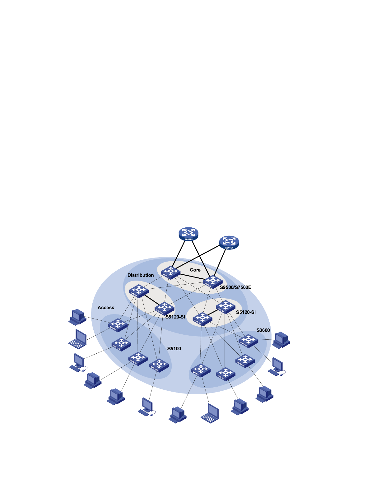
Distribution Layer Switches
In medium- and large-sized enterprises or campus networks, the S5120-SI series Ethernet switches
can serve as distribution layer switches that provide high-performance and large-capacity switching
service.
Figure 4-1 Application of the S5120-SI series at the distribution layer of enterprise networks/campus
networks
Page 15
4-2
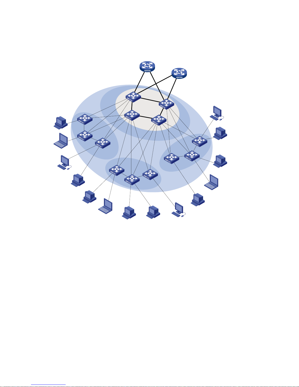
Access Switches
The S5120-SI series can serve as access switches to provide large access bandwidth and high port
density.
Figure 4-2 Application of the S5120-SI series at the access layer
S9500/S7500E
S5120-SI
Access
Core/Aggregation
S5120-SI
Page 16

i
Table of Contents
1 Logging In to an Ethernet Switch ············································································································1-1
Logging In to an Ethernet Switch············································································································1-1
Introduction to User Interface··················································································································1-1
Supported User Interfaces ··············································································································1-1
User Interface Number····················································································································1-1
Common Login in to an Ethernet Switch·································································································1-2
2 Logging In Through the Console Port·····································································································2-1
Introduction ·············································································································································2-1
Setting Up the Connection to the Console Port······················································································2-2
Console Port Login Configuration···········································································································2-3
Common Configuration····················································································································2-3
Console Port Login Configurations for Different Authentication Modes··········································2-4
Console Port Login Configuration with Authentication Mode Being None··············································2-5
Configuration Procedure··················································································································2-5
Configuration Example····················································································································2-7
Console Port Login Configuration with Authentication Mode Being Password······································2-8
Configuration Procedure··················································································································2-8
Configuration Example··················································································································2-10
Console Port Login Configuration with Authentication Mode Being Scheme·······································2-11
Configuration Procedure················································································································2-11
Configuration Example··················································································································2-13
3 Logging In Through Telnet/SSH···············································································································3-1
Introduction ·············································································································································3-1
Telnet Connection Establishment···········································································································3-2
Telnetting to a Switch from a Terminal····························································································3-2
Telnetting to Another Switch from the Current Switch ····································································3-3
Common Configuration···························································································································3-4
Telnet Configurations for Different Authentication Modes·······························································3-5
Telnet Configuration with Authentication Mode Being None ··································································3-5
Configuration Procedure··················································································································3-5
Configuration Example····················································································································3-7
Telnet Configuration with Authentication Mode Being Password···························································3-8
Configuration Procedure··················································································································3-8
Configuration Example····················································································································3-9
Telnet Configuration with Authentication Mode Being Scheme····························································3-10
Configuration Procedure················································································································3-10
Configuration Example··················································································································3-12
4 Logging in Through Web-based Network Management System··························································4-1
Introduction ·············································································································································4-1
Web Server Configuration·······················································································································4-1
Displaying Web Users·····························································································································4-2
Configuration Example····························································································································4-2
Page 17

ii
5 Logging In Through NMS··························································································································5-1
Introduction ·············································································································································5-1
Connection Establishment Using NMS···································································································5-1
6 Specifying Source for Telnet Packets·····································································································6-1
Introduction ·············································································································································6-1
Specifying Source IP address/Interface for Telnet Packets····································································6-1
Displaying the source IP address/Interface Specified for Telnet Packets··············································6-2
7 Controlling Login Users····························································································································7-1
Introduction ·············································································································································7-1
Controlling Telnet Users ·························································································································7-1
Prerequisites····································································································································7-1
Controlling Telnet Users by Source IP Addresses··········································································7-1
Controlling Telnet Users by Source and Destination IP Addresses················································7-2
Controlling Telnet Users by Source MAC Addresses ·····································································7-3
Configuration Example····················································································································7-3
Controlling Network Management Users by Source IP Addresses························································7-4
Prerequisites····································································································································7-4
Controlling Network Management Users by Source IP Addresses·················································7-4
Configuration Example····················································································································7-5
Controlling Web Users by Source IP Addresses····················································································7-6
Prerequisites····································································································································7-6
Controlling Web Users by Source IP Addresses·············································································7-6
Forcing Online Web Users Offline···································································································7-7
Configuration Example····················································································································7-7
Page 18

1-1
1 Logging In to an Ethernet Switch
When logging in to an Ethernet switch, go to these sections for information you are interested in:
z Logging In to an Ethernet Switch
z Introduction to User Interface
z Specifying Source for Telnet Packets
z Controlling Login Users
Logging In to an Ethernet Switch
You can log in to an H3C S5120-SI series Ethernet switch in one of the following ways:
z Logging In Through the Console Port
z Logging In Through Telnet/SSH
z Logging in Through Web-based Network Management System
z Logging In Through NMS
Introduction to User Interface
Supported User Interfaces
H3C S5120-SI series Ethernet switch supports two types of user interfaces: AUX and VTY.
Table 1-1 Description on user interface
User interface Applicable user Port used Description
AUX
Users logging in
through the Console
port
Console port
Each switch can
accommodate one
AUX user.
VTY
Telnet users and SSH
users
Ethernet port
Each switch can
accommodate up to
five VTY users.
As the AUX port and the Console port of a H3C series switch are the same one, you will be in the AUX
user interface if you log in through this port.
User Interface Number
Two kinds of user interfa ce index exist: absolute user interface index and relative user interface index.
1) The absolute user interface indexes are as follows:
z AUX user interface: 0
Page 19

1-2
z VTY user interfaces: Numbered after AUX user interfaces and increases in the step of 1
2) A relative user interface index can be obtained by appending a number to the identifier of a user
interface type. It is generated by user interface type. The relative user interface indexes are as
follows:
z AUX user interface: AUX 0
z VTY user interfaces: VTY 0, VTY 1, VTY 2, and so on.
Common Login in to an Ethernet Switch
Follow these steps to perform common user interface configuration:
T o do… Use the command… Remarks
Lock the current user interface
lock
Optional
Execute this command in user
view.
A user interface is not locked by
default.
Specify to send messages to all
user interfaces/a specified user
interface
send { all | number | type
number }
Optional
Execute this command in user
view.
Disconnect a specified user
interface
free user-interface [ type ]
number
Optional
Execute this command in user
view.
Enter system view
system-view
—
Set the banner
header { incoming | legal |
login | shell | motd } text
Optional
Set a system name for the
switch
sysname string
Optional
Enter user interface view
user-interface [ type ]
first-number [ last-number ]
—
Define a shortcut key for
aborting tasks
escape-key { default |
character }
Optional
The default shortcut key
combination for aborting tasks
is < Ctrl + C >.
Set the history command buffer
size
history-command max-size
value
Optional
The default history command
buffer size is 10. That is, a
history command buffer can
store up to 10 commands by
default.
Page 20

1-3
T o do… Use the command… Remarks
Set the timeout time for the
user interface
idle-timeout minutes
[ seconds ]
Optional
The default timeout time of a
user interface is 10 minutes.
With the timeout time being 10
minutes, the connection to a
user interface is terminated if
no operation is performed in the
user interface within 10
minutes.
You can use the idle-timeout 0
command to disable the
timeout function.
Set the maximum number of
lines the screen can contain
screen-length screen-length
Optional
By default, the screen can
contain up to 24 lines.
You can use the screen-length
0 command to disable the
function to display information
in pages.
Make terminal services
available
shell
Optional
By default, terminal services
are available in all user
interfaces.
Set the display type of a
terminal
terminal type { ansi | vt100 }
Optional
By default, the terminal display
type is ANSI. The device must
use the same type of display as
the terminal. If the terminal
uses VT 100, the device should
also use VT 100.
Display the information about
the current user interface/all
user interfaces
display users [ all ]
You can execute this command
in any view.
Display the physical attributes
and configuration of the
current/a specified user
interface
display user-interface [ type
number | number ] [ summary ]
You can execute this command
in any view.
Page 21

2-1
2 Logging In Through the Console Port
When logging in through the Console port, go to these sections for information you are interested in:
z Introduction
z Setting Up the Connection to the Console Port
z Console Port Login Configuration
z Console Port Login Configuration with Authentication Mode Being None
z Console Port Login Configuration with Authentication Mode Being Password
z Console Port Login Configuration with Authentication Mode Being Scheme
The default system name of an H3C S5120-SI series Ethernet switch is H3C, that is, the command line
prompt is H3C. All the following examples take H3C as the command line prompt.
Introduction
To log in through the Console port is the most common way to log in to a switch. It is also the
prerequisite to configure other login methods. By default, you can log in to an H3C S5120-SI series
Ethernet switch through its Console port only.
To log in to an Ethernet switch through its Console port, the related configuration of the user terminal
must be in accordance with that of the Console port.
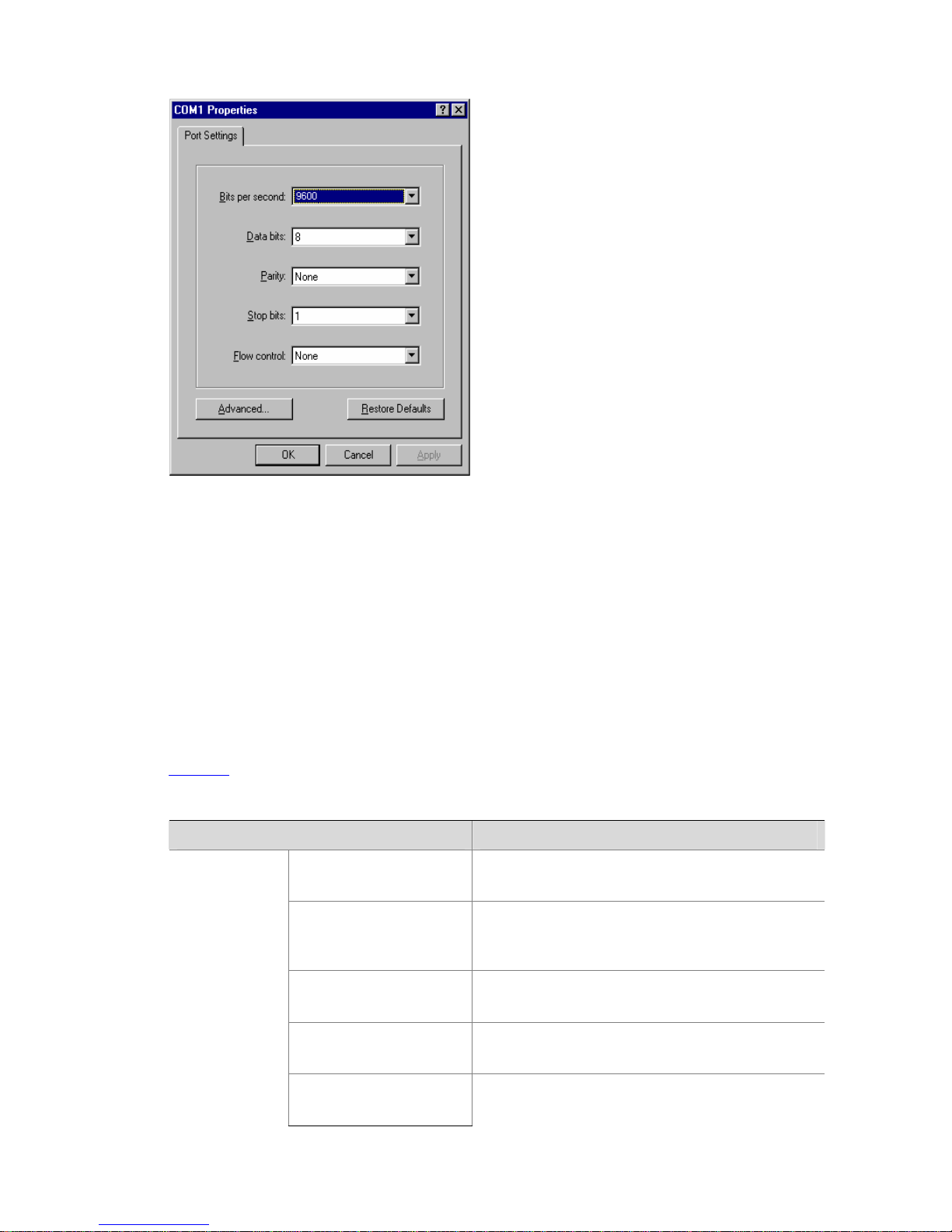
Table 2-1 lists the default settings of a Console port.
Table 2-1 The default settings of a Console port
Setting Default
Baud rate 9,600 bps
Flow control Off
Check mode No check bit
Stop bits 1
Data bits 8
After logging in to a switch, you can perform configuration for AUX users. Refer to
Console Port Login
Configuration
for details.
Page 22
2-2
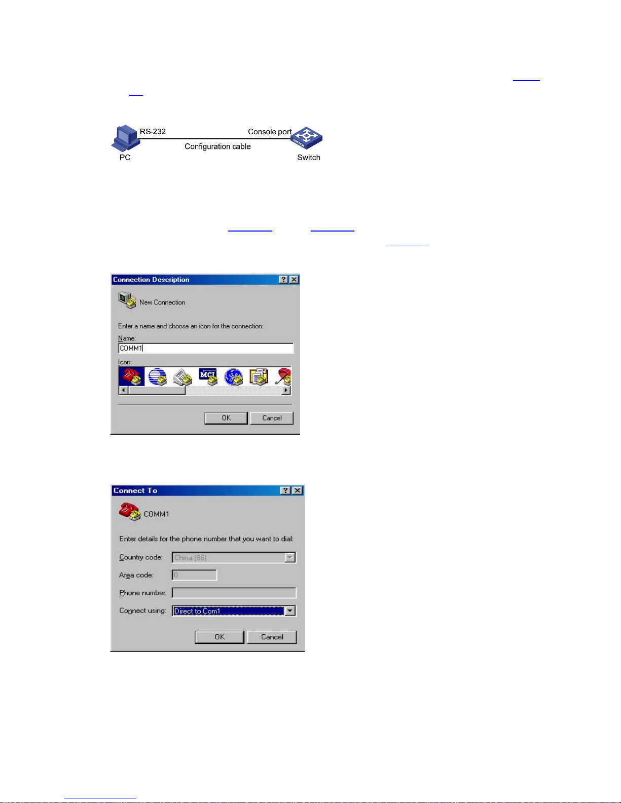
Setting Up the Connection to the Console Port
z Connect the serial port of your PC/terminal to the Console port of the switch, as shown in Figure
2-1.
Figure 2-1 Diagram for setting the connection to the Console port
z If you use a PC to connect to the Console port, launch a terminal emulation utility (such as Terminal
in Windows 3.X or HyperTerminal in Windows 9X/Windows 2000/Windows XP) and perform the
configuration shown in
Figure 2-2 through Figure 2-4 for the connection to be created. Normally,
the parameters of a terminal are configured as those listed in
Table 2-1.
Figure 2-2 Create a connection
Figure 2-3 Specify the port used to establish the connection
Page 23
2-3
Figure 2-4 Set port parameters terminal window
z Turn on the switch. The user will be prompted to press the Enter key if the switch successfully
completes POST (power-on self test). The prompt (such as <H3C>) appears after the user presses
the Enter key.
z You can then configure the switch or check the information about the switch by executing
commands. You can also acquire help by type the ? character. Refer to the following chapters for
information about the commands.
Console Port Login Configuration
Common Configuration
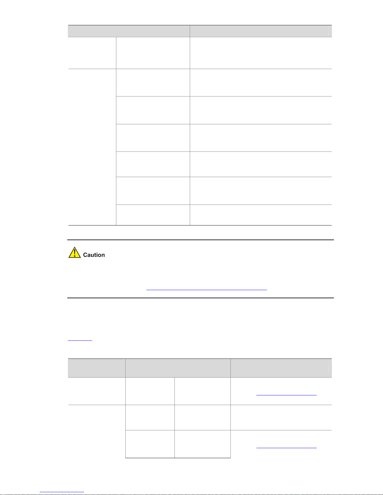
Table 2-2 lists the common configuration of Console port login.
Table 2-2 Common configuration of Console port login
Configuration Description
Baud rate
Optional
The default baud rate is 9,600 bps.
Check mode
Optional
By default, the check mode of the Console port is set
to “none”, which means no check bit.
Stop bits
Optional
The default stop bits of a Console port is 1.
Data bits
Optional
The default data bits of a Console port is 8.
Console port
configuration
Flow control
Optional
The default is none, which disables flow control.
Page 24
2-4
Configuration Description
AUX user
interface
configuration
Configure the command
level available to the
users logging in to the
AUX user interface
Optional
By default, commands of level 3 are available to the
users logging in to the AUX user interface.
Define a shortcut key for
aborting tasks
Optional
The default shortcut key combination for aborting
tasks is < Ctrl + C >.
Define a shortcut key for
starting terminal sessions
Optional
By default, pressing Enter key starts the terminal
session.
Make terminal services
available
Optional
By default, terminal services are available in all user
interfaces
Set the maximum number
of lines the screen can
contain
Optional
By default, the screen can contain up to 24 lines.
Set history command
buffer size
Optional
By default, the history command buffer can contain
up to 10 commands.
Terminal
configuration
Set the timeout time of a
user interface
Optional
The default timeout time is 10 minutes.
Changing of Console port configuration terminates the connection to the Console port. To establish the
connection again, you need to modify the configuration of the termination emulation utility running on
your PC accordingly. Refer to
Setting Up the Connection to the Console Port for details.
Console Port Login Configurations for Different Authentication Modes
Table 2-3 lists Console port login configurations for different authentication modes.
Table 2-3 Console port login configurations for different authentication modes
Authentication
mode
Console port login configuration Description
None
Perform
common
configuration
Perform common
configuration for
Console port login
Optional
Refer to
Common Configuration for
details.
Configure the
password
Configure the
password for local
authentication
Required
Password
Perform
common
configuration
Perform common
configuration for
Console port login
Optional
Refer to
Common Configuration for
details.
Page 25

2-5
Authentication
mode
Console port login configuration Description
Specify to
perform local
authentication
or RADIUS
authentication
AAA configuration
specifies whether
to perform local
authentication or
RADIUS
authentication
Optional
Local authentication is performed by
default.
Refer to the AAA Configuration for
details.
Configure user
name and
password
Configure user
names and
passwords for
local/remote users
Required
z The user name and password of
a local user are configured on the
switch.
z The user name and password of
a remote user are configured on
the RADIUS server. Refer to user
manual of RADIUS server for
details.
Manage AUX
users
Set service type for
AUX users
Required
Scheme
Perform
common
configuration
Perform common
configuration for
Console port login
Optional
Refer to
Common Configuration for
details.
Changes of the authentication mode of Console port login will not take effect unless you exit and enter
again the CLI.
Console Port Login Configuration with Authentication Mode Being
None
Configuration Procedure
Follow these steps to perform Console port login configuration (with authentication mode being none):
T o do… Use the command… Remarks
Enter system view
system-view
—
Enter AUX user interface view user-interface aux 0 —
Configure not to authenticate
users
authentication-mode none
Required
By default, users logging in through
the Console port are not
authenticated.
Configure
the Console
port
Set the baud
rate
speed speed-value
Optional
The default baud rate of an AUX
port (also the Console port) is 9,600
bps.
Page 26

2-6
T o do… Use the command… Remarks
Set the check
mode
parity { even | mark | none |
odd | space }
Optional
By default, the check mode of a
Console port is set to none, that is,
no check bit.
Set the stop
bits
stopbits { 1 | 1.5 | 2 }
Optional
The stop bits of a Console port is 1.
Set the data
bits
databits { 5 | 6 | 7 | 8 }
Optional
The default data bits of a Console
port is 8.
Configure the command level
available to users logging in to
the user interface
user privilege level level
Optional
By default, commands of level 3 are
available to users logging in to the
AUX user interface.
Define a shortcut key for
starting terminal sessions
activation-key character
Optional
By default, pressing Enter key
starts the terminal session.
Define a shortcut key for
aborting tasks
escape-key { default |
character }
Optional
The default shortcut key
combination for aborting tasks is <
Ctrl + C >.
Make terminal services
available
shell
Optional
By default, terminal services are
available in all user interfaces.
Set the maximum number of
lines the screen can contain
screen-length
screen-length
Optional
By default, the screen can contain
up to 24 lines.
You can use the screen-length 0
command to disable the function to
display information in pages.
Set the history command
buffer size
history-command
max-size value
Optional
The default history command buffer
size is 10. That is, a history
command buffer can store up to 10
commands by default.
Set the timeout time for the
user interface
idle-timeout minutes
[ seconds ]
Optional
The default timeout time of a user
interface is 10 minutes.
With the timeout time being 10
minutes, the connection to a user
interface is terminated if no
operation is performed in the user
interface within 10 minutes.
You can use the idle-timeout 0
command to disable the timeout
function.
Note that if you configure not to authenticate the users, the command level available to users logging in
to a switch depends on both the authentication-mode none command and the user privilege level
level command, as listed in the following table.
Page 27
2-7
Table 2-4 Determine the command level (A)
Scenario
Authentication
mode
User type Command
Command level
The user privilege level level
command not executed
Level 3
None
(authentication-mod
e none)
Users logging in
through
Console ports
The user privilege level level
command already executed
Determined by
the level
argument
Configuration Example
Network requirements
Assume the switch is configured to allow you to login through Telnet, and your user level is set to the
administrator level (level 3). After you telnet to the switch, you need to limit the console user at the
following aspects.
z The user is not authenticated when logging in through the Console port.
z Commands of level 2 are available to user logging in to the AUX user interface.
z The baud rate of the Console port is 19200 bps.
z The screen can contain up to 30 lines.
z The history command buffer can contain up to 20 commands.
z The timeout time of the AUX user interface is 6 minutes.
Network diagram
Figure 2-5 Network diagram for AUX user interface configuration (with the authentication mode being
none)
Configuration procedure
# Enter system view.
<Sysname> system-view
# Enter AUX user interface view.
[Sysname] user-interface aux 0
# Specify not to authenticate the user logging in through the Console port.
[Sysname-ui-aux0] authentication-mode none
Page 28

2-8
# Specify commands of level 2 are avai lable to the user logging in to the AUX user interfa ce.
[Sysname-ui-aux0] user privilege level 2
# Set the baud rate of the Console port to 19200 bps.
[Sysname-ui-aux0] speed 19200
# Set the maximum number of lines the screen can contain to 30.
[Sysname-ui-aux0] screen-length 30
# Set the maximum number of commands the history command buff er can store to 20.
[Sysname-ui-aux0] history-command max-size 20
# Set the timeout time of the AUX user interface to 6 minutes.
[Sysname-ui-aux0] idle-timeout 6
After the above configuration, to ensure a successful login, the console user needs to change the
corresponding configuration of the terminal emulation program running on the PC, to make the
configuration consistent with that on the switch. Refer to
Setting Up the Connection to the Console Port
for details.
Console Port Login Configuration with Authentication Mode Being
Password
Configuration Procedure
Follow these steps to perform Console port login configuration (with authentication mode being
password):
T o do… Use the command… Remarks
Enter system view
system-view
—
Enter AUX user interface
view
user-interface aux 0 —
Configure to authenticate
users using the local
password
authentication-mode
password
Required
By default, users logging in through the
Console port are not authenticated, while
users logging in through the Telnet need
to pass the password authentication.
Set the local password
set authentication
password { cipher |
simple } password
Required
Page 29

2-9
T o do… Use the command… Remarks
Set the
baud rate
speed speed-value
Optional
The default baud rate of an AUX port
(also the Console port) is 9,600 bps.
Set the
check
mode
parity { even | mark | none
| odd | space }
Optional
By default, the check mode of a Console
port is set to none, that is, no check bit.
Set the stop
bits
stopbits { 1 | 1.5 | 2 }
Optional
The default stop bits of a Console port is
1.
Configure
the
Console
port
Set the
data bits
databits { 5 | 6 | 7 | 8 }
Optional
The default data bits of a Console port is
8.
Configure the command
level available to users
logging in to the user
interface
user privilege level level
Optional
By default, commands of level 3 are
available to users logging in to the AUX
user interface.
Define a shortcut key for
starting terminal sessions
activation-key character
Optional
By default, pressing Enter key starts the
terminal session.
Define a shortcut key for
aborting tasks
escape-key { default |
character }
Optional
The default shortcut key combination for
aborting tasks is < Ctrl + C >.
Make terminal services
available to the user
interface
shell
Optional
By default, terminal services are
available in all user interfaces.
Set the maximum number
of lines the screen can
contain
screen-length
screen-length
Optional
By default, the screen can contain up to
24 lines.
You can use the screen-length 0
command to disable the function to
display information in pages.
Set history command
buffer size
history-command
max-size value
Optional
The default history command buffer size
is 10. That is, a history command buffer
can store up to 10 commands by default.
Set the timeout time for
the user interface
idle-timeout minutes
[ seconds ]
Optional
The default timeout time of a user
interface is 10 minutes.
With the timeout time being 10 minutes,
the connection to a user interface is
terminated if no operation is performed in
the user interface within 10 minutes.
You can use the idle-timeout 0
command to disable the timeout
function.
Page 30
2-10
Note that if you configure to authenticate the users in the password mode, the command level available
to users logging in to a switch depends on both the authentication-mode password and the user
privilege level level command, as listed in the following table.
Table 2-5 Determine the command level (B)
Scenario
Authentication mode User type Command
Command level
The user privilege level level
command not executed
Level 3
Local authentication
(authentication-mode
password)
Users logging in to
the AUX user
interface
The user privilege level level
command already executed
Determined by
the level
argument
Configuration Example
Network requirements
Assume the switch is configured to allow you to login through Telnet, and your user level is set to the
administrator level (level 3). After you telnet to the switch, you need to limit the Console user at the
following aspects.
z The user is authenticated against the local password when logging in through the Console port.
z The local password is set to 123456 (in plain text).
z The commands of level 2 are available to users logging in to the AUX user interface.
z The baud rate of the Console port is 19,200 bps.
z The screen can contain up to 30 lines.
z The history command buffer can store up to 20 commands.
z The timeout time of the AUX user interface is 6 minutes.
Network diagram
Figure 2-6 Network diagram for AUX user interface configuration (with the authentication mode being
password)
Configuration procedure
# Enter system view.
<Sysname> system-view
# Enter AUX user interface view.
Page 31

2-11
[Sysname] user-interface aux 0
# Specify to authenticate the user logging in through the Console port using the local password.
[Sysname-ui-aux0] authentication-mode password
# Set the local password to 123456 (in plain text).
[Sysname-ui-aux0] set authentication password simple 123456
# Specify commands of level 2 are avai lable to the user logging in to the AUX user interfa ce.
[Sysname-ui-aux0] user privilege level 2
# Set the baud rate of the Console port to 19200 bps.
[Sysname-ui-aux0] speed 19200
# Set the maximum number of lines the screen can contain to 30.
[Sysname-ui-aux0] screen-length 30
# Set the maximum number of commands the history command buff er can store to 20.
[Sysname-ui-aux0] history-command max-size 20
# Set the timeout time of the AUX user interface to 6 minutes.
[Sysname-ui-aux0] idle-timeout 6
After the above configuration, to ensure a successful login, the console user needs to change the
corresponding configuration of the terminal emulation program running on the PC, to make the
configuration consistent with that on the switch. Refer to
Setting Up the Connection to the Console Port
for details.
Console Port Login Configuration with Authentication Mode Being
Scheme
Configuration Procedure
Follow these steps to perform Console port login configuration (with authentication mode being
scheme):
Page 32

2-12
T o do… Use the command… Remarks
Enter system view
system-view
—
Enter the
default ISP
domain
view
domain domain name
Specify the
AAA
scheme to
be applied
to the
domain
authentication default
{ local | none |
radius-scheme
radius-scheme-name
[ local ] }
Configure
the
authentica
tion mode
Quit to
system
view
quit
Optional
By default, the local AAA scheme is
applied. If you specify to apply the local
AAA scheme, you need to perform the
configuration concerning local user as
well.
If you specify to apply an existing scheme
by providing the radius-scheme-name
argument, you need to perform the
following configuration as well:
z Perform AAA-RADIUS configuration
on the switch. (Refer to AAA
Configuration for details.)
z Configure the user name and
password accordingly on the AAA
server. (Refer to the user manual of
AAA server.)
Create a local user
(Enter local user view.)
local-user user-name
Required
No local user exists by default.
Set the authentication
password for the local
user
password { simple |
cipher } password
Required
Specify the service type
for AUX users
service-type terminal
Required
Quit to system view
quit
—
Enter AUX user interface
view
user-interface aux 0 —
Configure to authenticate
users locally or remotely
authentication-mode
scheme [ commandauthorization ]
Required
The specified AAA scheme determines
whether to authenticate users locally or
remotely.
Users are authenticated locally by default.
Set the
baud rate
speed speed-value
Optional
The default baud rate of the AUX port
(also the Console port) is 9,600 bps.
Set the
check
mode
parity { even | mark | none
| odd | space }
Optional
By default, the check mode of a Console
port is set to none, that is, no check bit.
Set the
stop bits
stopbits { 1 | 1.5 | 2 }
Optional
The default stop bits of a Console port is 1.
Configure
the Console
port
Set the
data bits
databits { 5 | 6 | 7 | 8 }
Optional
The default data bits of a Console port is 8.
Configure the command
level available to users
logging in to the user
interface
user privilege level level
Optional
By default, commands of level 3 are
available to users logging in to the AUX
user interface.
Page 33

2-13
T o do… Use the command… Remarks
Define a shortcut key for
starting terminal
sessions
activation-key character
Optional
By default, pressing Enter key starts the
terminal session.
Define a shortcut key for
aborting tasks
escape-key { default |
character }
Optional
The default shortcut key combination for
aborting tasks is < Ctrl + C >.
Make terminal services
available to the user
interface
shell
Optional
By default, terminal services are available
in all user interfaces.
Set the maximum
number of lines the
screen can contain
screen-length
screen-length
Optional
By default, the screen can contain up to 24
lines.
You can use the screen-length 0
command to disable the function to
display information in pages.
Set history command
buffer size
history-command
max-size value
Optional
The default history command buffer size is
10. That is, a history command buffer can
store up to 10 commands by default.
Set the timeout time for
the user interface
idle-timeout minutes
[ seconds ]
Optional
The default timeout time of a user
interface is 10 minutes.
With the timeout time being 10 minutes,
the connection to a user interface is
terminated if no operation is performed in
the user interface within 10 minutes.
You can use the idle-timeout 0 command
to disable the timeout function.
Note that the level the commands of which are available to user s loggin g in to a switch depen ds on the
authentication-mode scheme [ command-authorization ] command, and the user privilege level
level command.
Configuration Example
Network requirements
Assume the switch is configured to allow you to login through Telnet, and your user level is set to the
administrator level (level 3). After you telnet to the switch, you need to limit the console user at the
following aspects.
z Configure the name of the local user to be “guest”.
z Set the authentication password of the local user to 123456 (in plain text).
z Set the service type of the local user to Terminal.
z Configure to authenticate the user logging in through the Console port in the scheme mode.
z The baud rate of the Console port is 19,200 bps.
z The screen can contain up to 30 lines.
z The history command buffer can store up to 20 commands.
z The timeout time of the AUX user interface is 6 minutes.
Page 34

2-14
Network diagram
Figure 2-7 Network diagram for AUX user interface configuration (with the authentication mode being
scheme)
Configuration procedure
# Enter system view.
<Sysname> system-view
# Create a local user named guest and enter local user view.
[Sysname] local-user guest
# Set the authentication password to 123456 (in plain text).
[Sysname-luser-guest] password simple 123456
# Set the service type to Terminal.
[Sysname-luser-guest] service-type terminal
[Sysname-luser-guest] quit
# Enter AUX user interface view.
[Sysname] user-interface aux 0
# Configure to authenticate the user logging in through the Console port in the scheme mode.
[Sysname-ui-aux0] authentication-mode scheme
# Set the baud rate of the Console port to 19200 bps.
[Sysname-ui-aux0] speed 19200
# Set the maximum number of lines the screen can contain to 30.
[Sysname-ui-aux0] screen-length 30
# Set the maximum number of commands the history command buff er can store to 20.
[Sysname-ui-aux0] history-command max-size 20
# Set the timeout time of the AUX user interface to 6 minutes.
[Sysname-ui-aux0] idle-timeout 6
After the above configuration, to ensure a successful login, the console user needs to change the
corresponding configuration of the terminal emulation program running on the PC, to make the
configuration consistent with that on the switch. Refer to
Setting Up the Connection to the Console Port
for details.
Page 35

3-1
3 Logging In Through Telnet/SSH
When logging in through Telnet, go to these sections for information you are interested in:
z Introduction
z Telnet Configuration with Authentication Mode Being None
z Telnet Configuration with Authentication Mode Being Password
z Telnet Configuration with Authentication Mode Being Scheme
z Telnet Connection Establishment
Introduction
You can telnet to a remote switch to manage and maintain the switch. To achieve this, you need to
configure both the switch and the Telnet terminal properly.
Table 3-1 Requirements for Telnet to a switch
Item Requirement
Start the Telnet Server
The IP address of the VLAN of the switch is
configured and the route between the switch and
the Telnet terminal is available.
Switch
The authentication mode and other settings are
configured. Refer to
Table 3-2 and T able 3-3.
Telnet is running.
Telnet terminal
The IP address of the management VLAN of the
switch is available.
z After you log in to the switch through Telnet, you can issue commands to the switch by way of
pasting session text, which cannot exceed 2000 bytes, and the pasted commands must be in the
same view; otherwise, the switch may not execute the commands correctly.
z If the session text exceeds 2000 bytes, you can save it in a configuration file, upload the
configuration file to the switch and reboot the switch with this configuration file. For detail s, refer to
File System Management.
Page 36

3-2
Telnet Connection Establishment
Telnetting to a Switch from a Terminal
Y ou can telnet to a switch and then configure the switch if the interface of the management VLAN of the
switch is assigned with an IP address. (By default, VLAN 1 is the management VLAN.)
Following are procedures to establish a Telnet connection to a switch:
Step 1: Log in to the switch through the Console port, enable the Telnet server function and assign an IP
address to the management VLAN interface of the switch.
z Connect to the Console port. Refer to Setting Up the Connection to the Console Port.
z Execute the following commands in the terminal window to enable the Telnet server function and
assign an IP address to the management VLAN interface of the switch.
# Enable the T elnet server function and configure the IP address of the managem ent VLAN interface as
202.38.160.92, and .the subnet mask as 255.255.255.0.
<Sysname> system-view
[Sysname] telnet server enable
[Sysname] interface vlan-interface 1
[Sysname-Vlan-interface1] ip address 202.38.160.92 255.255.255.0
Step 2: Before Telnet users can log in to the switch, corresponding configurations should have been
performed on the switch according to different authentication modes for them. Refer to
Telnet
Configuration with Authentication Mode Being None
, Telnet Configuration with Authentication Mode
Being Password
, and Telnet Configuration with Authentication Mode Being Scheme for details. By
default, Telnet users need to pass the password authentication to login.
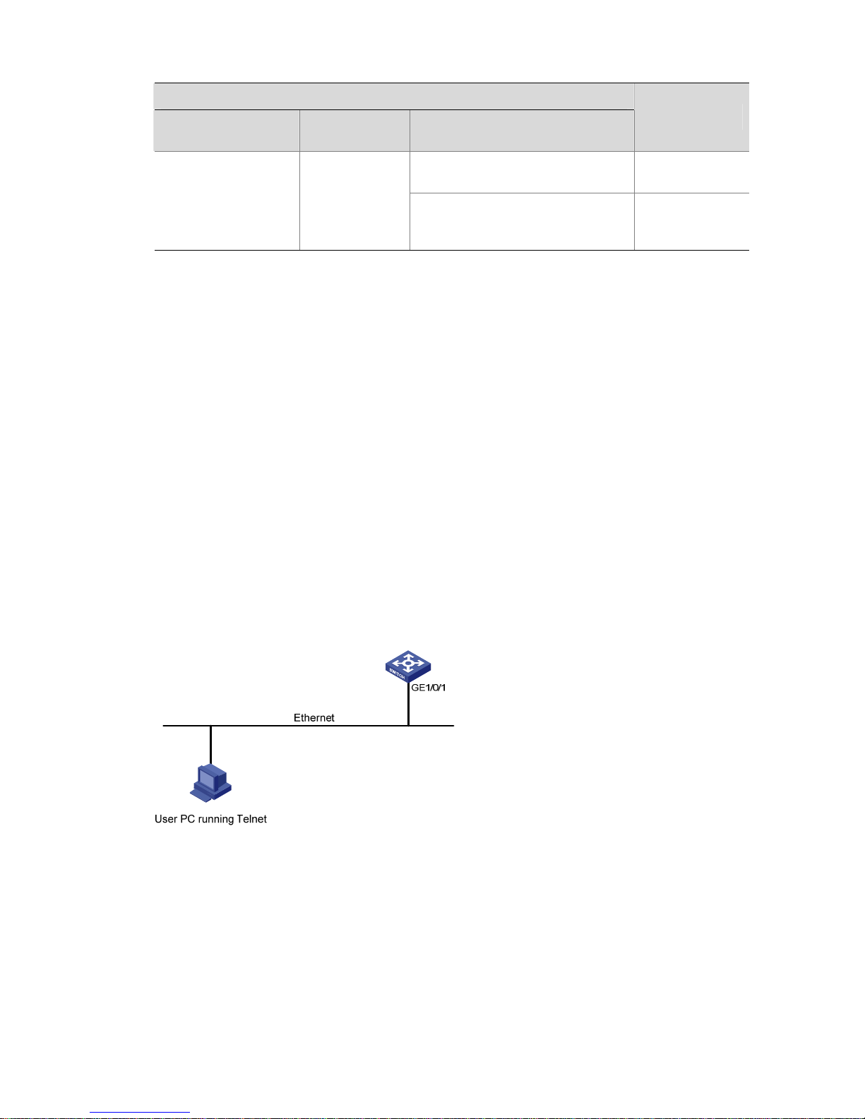
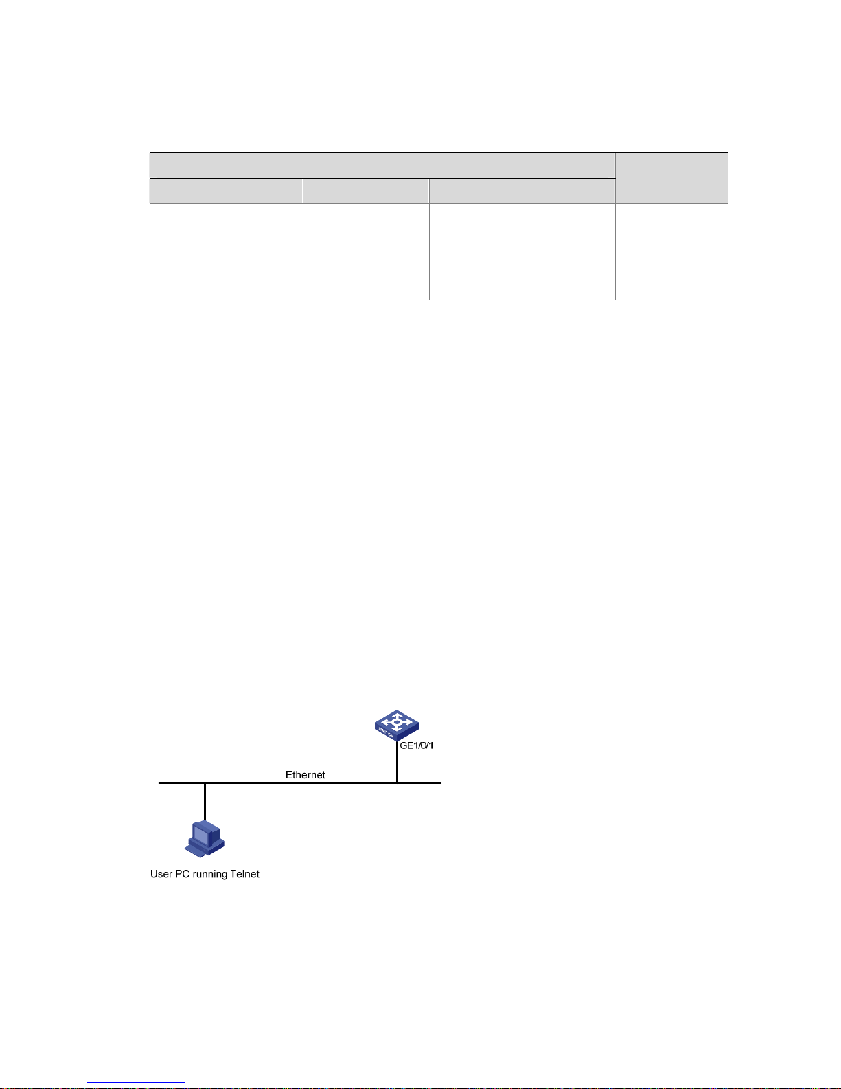
Step 3: Connect your PC to the Switch, as shown in
Figure 3-1. Make sure the Ethernet port to which
your PC is connected belongs to the management VLAN of the switch and the route between your PC
and the switch is available.
Figure 3-1 Network diagram for Telnet connection establishment
Configuration PC
running Telnet
Ethernet
WorkstationServer
Workstation
Ethernet port
Step 4: Launch Telnet on your PC, with the IP address of the management VLAN interface of the switch
as the parameter , as shown in the following figure.
Page 37

3-3
Figure 3-2 Launch Telnet
Step 5: Enter the password when the Telnet window displays “Login authentication” and prompts for
login password. The CLI prompt (such as <H3C>) appears if the password is correct. If all VTY user
interfaces of the switch are in use, you will fail to establish the connection and re ceive the message that
says “All user interfaces are used, please try later!”. A H3C series Ethern et switch can accommodate up
to five Telnet connections at same time.
Step 6: Af ter successfully Telnetting to a switch, you can configure the switch or display the information
about the switch by executing corresponding commands. You can also type ? at any time for help. Refer
to the following chapters for the information about the commands.
z A Telnet connection will be terminated if you delete or modify the IP address of the VLAN interface
in the Telnet session.
z By default, commands of level 0 are available to Telnet users authen ticated by pa ssword. Refe r to
Basic System Configuration for information about com mand hierarchy.
Telnetting to Another Switch from the Current Switch
Y ou can Telnet to another switch from the current switch. In this case, the current switch operates as the
client, and the other operates as the server. If the interconnected Ethernet port s of the two switches are
in the same LAN segment, make sure the IP addresses of the two management VLAN interfaces to
which the two Ethernet ports belong to are of the same network segment, or the route between the two
VLAN interfaces is available.
As shown in
Figure 3-3, after Telnetting to a switch (labeled as Telnet client), you can T elnet to another
switch (labeled as Telnet server) by executing the telnet command and then to configure the later .
Figure 3-3 Network diagram for Telnetting to another switch from the current switch
Step 1: Configure the user name and password for Telnet on the switch operating as the Telnet server.
Refer to section
Telnet Configuration with Authentication Mode Being None”, section Telnet
Configuration with Authentication Mode Being Password
, and Telnet Configuration with Authentication
Page 38

3-4
Mode Being Scheme for details. By default, Telnet users need to pass the password authentication to
login.
Step 2: Telnet to the switch operating as the Telnet client.
Step 3: Execute the following command on the switch operating as the Telnet client:
<Sysname> telnet xxxx
Where xxxx is the IP address or the host name of the switch ope rating as the Telnet server. You can use
the ip host to assign a host name to a switch.
Step 4: Enter the password. If the password is correct, the CLI prompt (such as <H3C>) appears. If all
VTY user interfaces of the switch are in use, you will fail to establish the connection and receive the
message that says “All user interfaces are used, please try later!”.
Step 5: After successfully Telnetting to the switch, you can configure the switch or display the
information about the switch by executing corresponding commands. Y ou can also type ? at any time for
help. Refer to the following chapters for the information about the commands.
Common Configuration
Table 3-2 lists the common Telnet configuration.
Table 3-2 Common Telnet configuration
Configuration Remarks
Configure the command level
available to users logging in to
the VTY user interface
Optional
By default, commands of level 0 are available
to users logging in to a VTY user interface.
Configure the protocols the user
interface supports
Optional
By default, Telnet and SSH protocol are
supported.
VTY user
interface
configuration
Set the command that is
automatically executed when a
user logs into the user interface
Optional
By default, no command is automatically
executed when a user logs into a user
interface.
Define a shortcut key for
aborting tasks
Optional
The default shortcut key combination for
aborting tasks is < Ctrl + C >.
Make terminal services
available
Optional
By default, terminal services are available in
all user interfaces
Set the maximum number of
lines the screen can contain
Optional
By default, the screen can contain up to 24
lines.
Set history command buffer size
Optional
By default, the history command buffer can
contain up to 10 commands.
VTY terminal
configuration
Set the timeout time of a user
interface
Optional
The default timeout time is 10 minutes.
Page 39

3-5
z The auto-execute command command may cause you unable to perform common configurat ion
in the user interface, so use it with caution.
z Before executing the auto-execute command command and save your configuration, make sure
you can log in to the switch in other modes and cancel the configuration.
Telnet Configurations for Different Authentication Modes
Table 3-3 lists Telnet configurations for different authentication modes.
Table 3-3 Telnet configurations for different authentication modes
Authentication
mode
T elnet configuration Remarks
None
Perform common
configuration
Perform common
Telnet configuration
Optional
Refer to
Table 3-2.
Configure the
password
Configure the
password for local
authentication
Required
Password
Perform common
configuration
Perform common
Telnet configuration
Optional
Refer to
Table 3-2.
Specify to perform
local
authentication or
RADIUS
authentication
AAA configuration
specifies whether to
perform local
authentication or
RADIUS
authentication
Optional
Local authentication is performed
by default.
Refer to AAA Configuration for
details.
Configure user
name and
password
Configure user
names and
passwords for
local/remote users
Required
z The user name and password
of a local user are configured
on the switch.
z The user name and password
of a remote user are configured
on the RADIUS server. Refer to
user manual of RADIUS server
for details.
Manage VTY
users
Set service type for
VTY users
Required
Scheme
Perform common
configuration
Perform common
Telnet configuration
Optional
Refer to
Table 3-2.
Telnet Configuration with Authentication Mode Being None
Configuration Procedure
Follow these steps to perform Telnet configuration (with authentication mode being none):
Page 40

3-6
T o do… Use the command… Remarks
Enter system view
system-view
—
Enter one or more VTY user
interface views
user-interface vty first-number
[ last-number ]
—
Configure not to authenticate
users logging in to VTY user
interfaces
authentication-mode none
Required
By default, VTY users are
authenticated after logging in.
Configure the command level
available to users logging in to
VTY user interface
user privilege level level
Optional
By default, commands of level
0 are available to users logging
in to VTY user interfaces.
Configure the protocols to be
supported by the VTY user
interface
protocol inbound { all | ssh |
telnet }
Optional
By default, both Telnet protocol
and SSH protocol are
supported.
Set the command that is
automatically executed when a
user logs into the user interface
auto-execute command text
Optional
By default, no command is
automatically executed when a
user logs into a user interface.
Define a shortcut key for
aborting tasks
escape-key { default |
character }
Optional
The default shortcut key
combination for aborting tasks
is < Ctrl + C >.
Make terminal services
available
shell
Optional
By default, terminal services
are available in all user
interfaces.
Set the maximum number of
lines the screen can contain
screen-length screen-length
Optional
By default, the screen can
contain up to 24 lines.
Y ou can u se the screen-length
0 command to disable the
function to display information
in pages.
Set the history command buffer
size
history-command max-size
value
Optional
The default history command
buffer size is 10. That is, a
history command buffer can
store up to 10 commands by
default.
Set the timeout time of the VTY
user interface
idle-timeout minutes
[ seconds ]
Optional
The default timeout time of a
user interface is 10 minutes.
With the timeout time being 10
minutes, the connection to a
user interface is terminated if
no operation is performed in the
user interface within 10
minutes.
You can use the idle-timeout 0
command to disable the
timeout function.
Page 41

3-7
Note that if you configure not to authenticate the users, the command level available to users logging in
to a switch depends on both the authentication-mode none command and the user privilege level
level command, as listed in
Table 3-4.
Table 3-4 Determine the command level when users logging in to switches are not authenticated
Scenario
Authentication
mode
User type Command
Command level
The user privilege level level
command not executed
Level 0
None
(authentication-mod
e none)
VTY users
The user privilege level level
command already executed
Determined by
the level
argument
Configuration Example
Network requirements
Assume that you are a level 3 AUX user and want to perform the following configuration fo r Telnet users
logging in to VTY 0:
z Do not authenticate users logging in to VTY 0.
z Commands of level 2 are available to users logging in to VTY 0.
z Telnet protocol is supported.
z The screen can contain up to 30 lines.
z The history command buffer can contain up to 20 commands.
z The timeout time of VTY 0 is 6 minutes.
Network diagram
Figure 3-4 Network diagram for Telnet configuration (with the authentication mode being none)
Configuration procedure
# Enter system view, and enable the Telnet service.
<Sysname> system-view
[Sysname] telnet server enable
# Enter VTY 0 user interface view.
[Sysname] user-interface vty 0
# Configure not to authenticate Telnet users logging in to VTY 0.
[Sysname-ui-vty0] authentication-mode none
# Specify commands of level 2 are avai lable to users logging in to VTY 0.
[Sysname-ui-vty0] user privilege level 2
Page 42

3-8
# Configure Telnet protocol is supported.
[Sysname-ui-vty0] protocol inbound telnet
# Set the maximum number of lines the screen can contain to 30.
[Sysname-ui-vty0] screen-length 30
# Set the maximum number of commands the history command buff er can store to 20.
[Sysname-ui-vty0] history-command max-size 20
# Set the timeout time to 6 minutes.
[Sysname-ui-vty0] idle-timeout 6
Telnet Configuration with Authentication Mode Being Password
Configuration Procedure
Follow these steps to perform Telnet configuration (with authentication mode being password):
T o do… Use the command… Remarks
Enter system view
system-view
—
Enter one or more VTY user
interface views
user-interface vty first-number
[ last-number ]
—
Configure to authenticate users
logging in to VTY user
interfaces using the local
password
authentication-mode
password
Required
Set the local password
set authentication password
{ cipher | simple } password
Required
Configure the command level
available to users logging in to
the user interface
user privilege level level
Optional
By default, commands of level
0 are available to users logging
in to VTY user interface.
Configure the protocol to be
supported by the user interface
protocol inbound { all | ssh |
telnet }
Optional
By default, both Telnet protocol
and SSH protocol are
supported.
Set the command that is
automatically executed when a
user logs into the user interface
auto-execute command text
Optional
By default, no command is
automatically executed when a
user logs into a user interface.
Define a shortcut key for
aborting tasks
escape-key { default |
character }
Optional
The default shortcut key
combination for aborting tasks
is < Ctrl + C >.
Make terminal services
available
shell
Optional
By default, terminal services
are available in all user
interfaces.
Page 43

3-9
T o do… Use the command… Remarks
Set the maximum number of
lines the screen can contain
screen-length screen-length
Optional
By default, the screen can
contain up to 24 lines.
Y ou can u se the screen-length
0 command to disable the
function to display information
in pages.
Set the history command buffer
size
history-command max-size
value
Optional
The default history command
buffer size is 10. That is, a
history command buffer can
store up to 10 commands by
default.
Set the timeout time of the user
interface
idle-timeout minutes
[ seconds ]
Optional
The default timeout time of a
user interface is 10 minutes.
With the timeout time being 10
minutes, the connection to a
user interface is terminated if
no operation is performed in the
user interface within 10
minutes.
You can use the idle-timeout 0
command to disable the
timeout function.
Note that if you configure to authenticate the users in the password mode, the command level available
to users logging in to a switch depends on both the authentication-mode password command and the
user privilege level level command, as listed in
Table 3-5.
Table 3-5 Determine the command level when users logging in to switches are authenticated in the
password mode
Scenario
Authentication
mode
User type Command
Command level
The user privilege level level
command not executed
Level 0
Password
(authentication-mo
de password)
VTY users
The user privilege level level
command already executed
Determined by
the level
argument
Configuration Example
Network requirements
Assume that you are a level 3 AUX user and want to perform the following configuration fo r Telnet users
logging in to VTY 0:
z Authenticate users logging in to VTY 0 using the local password.
z Set the local password to 123456 (in plain text).
Page 44

3-10
z Commands of level 2 are available to users logging in to VTY 0.
z Telnet protocol is supported.
z The screen can contain up to 30 lines.
z The history command buffer can contain up to 20 commands.
z The timeout time of VTY 0 is 6 minutes.
Network diagram
Figure 3-5 Network diagram for Telnet configuration (with the authentication mode being password)
Configuration procedure
# Enter system view, and enable the Telnet service.
<Sysname> system-view
[Sysname] telnet server enable
# Enter VTY 0 user interface view.
[Sysname] user-interface vty 0
# Configure to authenticate users logging in to VTY 0 using the local password.
[Sysname-ui-vty0] authentication-mode password
# Set the local password to 123456 (in plain text).
[Sysname-ui-vty0] set authentication password simple 123456
# Specify commands of level 2 are avai lable to users logging in to VTY 0.
[Sysname-ui-vty0] user privilege level 2
# Configure Telnet protocol is supported.
[Sysname-ui-vty0] protocol inbound telnet
# Set the maximum number of lines the screen can contain to 30.
[Sysname-ui-vty0] screen-length 30
# Set the maximum number of commands the history command buff er can store to 20.
[Sysname-ui-vty0] history-command max-size 20
# Set the timeout time to 6 minutes.
[Sysname-ui-vty0] idle-timeout 6
Telnet Configuration with Authentication Mode Being Scheme
Configuration Procedure
Follow these steps to perform Telnet configuration (with authentication mode being scheme):
Page 45

3-11
T o do… Use the command… Remarks
Enter system view
system-view
—
Enter the
default ISP
domain view
domain domain name
Configure
the AAA
scheme to
be applied to
the domain
authentication default
{ local | none |
radius-scheme
radius-scheme-name
[ local ] }
Configure
the
authenticati
on scheme
Quit to
system view
quit
Optional
By default, the local AAA scheme is
applied. If you specify to apply the
local AAA scheme, you need to
perform the configuration concerning
local user as well.
If you specify to apply an existing
scheme by providing the
radius-scheme-name argument, you
need to perform the following
configuration as well:
z Perform AAA-RADIUS
configuration on the switch. (Refer
to AAA Configuration for details.)
z Configure the user name and
password accordingly on the AAA
server. (Refer to the user manual
of AAA server.)
Create a local user and
enter local user view
local-user user-name
No local user exists by default.
Set the authentication
password for the local user
password { simple |
cipher } password
Required
Specify the service type for
VTY users
service-type telnet
Required
Quit to system view
quit
—
Enter one or more VTY user
interface views
user-interface vty
first-number [ last-number ]
—
Configure to authenticate
users locally or remotely
authentication-mode
scheme
Required
The specified AAA scheme
determines whether to authenticate
users locally or remotely.
Users are authenticated locally by
default.
Configure the command
level available to users
logging in to the user
interface
user privilege level level
Optional
By default, commands of level 0 are
available to users logging in to the
VTY user interfaces.
Configure the supported
protocol
protocol inbound { all | ssh
| telnet }
Optional
Both T elnet protocol an d SSH protocol
are supported by default.
Set the command that is
automatically executed
when a user logs into the
user interface
auto-execute command
text
Optional
By default, no command is
automatically executed when a user
logs into a user interface.
Define a shortcut key for
aborting tasks
escape-key { default |
character }
Optional
The default shortcut key combination
for aborting tasks is < Ctrl + C >.
Page 46

3-12
T o do… Use the command… Remarks
Make terminal services
available
shell
Optional
Terminal services are available in all
use interfaces by default.
Set the maximum number
of lines the screen can
contain
screen-length
screen-length
Optional
By default, the screen can contain up
to 24 lines.
You can use the screen-length 0
command to disable the function to
display information in pages.
Set history command buffer
size
history-command
max-size value
Optional
The default history command buffer
size is 10. That is, a history command
buffer can store up to 10 commands
by default.
Set the timeout time for the
user interface
idle-timeout minutes
[ seconds ]
Optional
The default timeout time of a user
interface is 10 minutes.
With the timeout time being 10
minutes, the connection to a user
interface is terminated if no operation
is performed in the user interface
within 10 minutes.
You can use the idle-timeout 0
command to disable the timeout
function.
Note that if you configure to authenticate the users in the scheme mode, the command level available to
users logging in to a switch depends on the authentication-mode scheme
[ command-authorization ] command and the user privilege level level command.
Refer to AAA Configuration and SSH2.0 Configuration for configuration about AAA, RADIUS and SSH..
Configuration Example
Network requirements
Assume that you are a level 3 AUX user and want to perform the following configuration fo r Telnet users
logging in to VTY 0:
z Configure the name of the local user to be “guest”.
z Set the authentication password of the local user to 123456 (in plain text).
z Set the service type of VTY users to Telnet.
z Configure to authenticate users logging in to VTY 0 in scheme mode.
z The commands of level 2 are available to users logging in to VTY 0.
z Telnet protocol is supported in VTY 0.
Page 47

3-13
z The screen can contain up to 30 lines.
z The history command buffer can store up to 20 commands.
z The timeout time of VTY 0 is 6 minutes.
Network diagram
Figure 3-6 Network diagram for Telnet configuration (with the authentication mode being scheme)
Configuration procedure
# Enter system view, and enable the Telnet service.
<Sysname> system-view
[Sysname] telnet server enable
# Create a local user named guest and enter local user view.
[Sysname] local-user guest
# Set the authentication password of the local user to 123456 (in plain text).
[Sysname-luser-guest] password simple 123456
# Set the service type to Telnet.
[Sysname-luser-guest] service-type
# Enter VTY 0 user interface view.
[Sysname] user-interface vty 0
# Configure to authenticate users logging in to VTY 0 in the scheme mode.
[Sysname-ui-vty0] authentication-mode scheme
# Configure Telnet protocol is supported.
[Sysname-ui-vty0] protocol inbound telnet
# Set the maximum number of lines the screen can contain to 30.
[Sysname-ui-vty0] screen-length 30
# Set the maximum number of commands the history command buff er can store to 20.
[Sysname-ui-vty0] history-command max-size 20
# Set the timeout time to 6 minutes.
[Sysname-ui-vty0] idle-timeout 6
Page 48

4-1
4 Logging in Through Web-based Network
Management System
Introduction
An S5120-SI series switch has a Web server built in. You can log in to an S5120-SI series switch
through a Web browser and manage and maintain the switch intuitively by interacting with the built-in
Web server .
To log in to an S5120-SI series switch through the built-in Web-based network management system,
you need to perform the related configuration on both the switch and the PC operating as the network
management terminal.
Table 4-1 Requirements for logging in to a switch through the Web-based network management
system
Item Requirement
Start the Web server
The IP address of the management VLAN of the switch is configured.
The route between the switch and the network management termin al
is available. (Refer to the module “IP Addressing and Performance”
and “IP Routing” for more.)
Switch
The user name and password for logging in to the Web-based
network management system are configured.
IE is available.
PC operating as the
network management
terminal
The IP address of the management VLAN interface of the switch is
available.
Web Server Configuration
Logging in Through Web-base d Network Management configuration.
To do… Use the command… Remarks
Enter system view
system-view
-
Add a local user and enter local
user view
local-user user-name
Required
No local user exists by default.
Configure a password for the
local user
password { cipher | simple }
password
Required
No password exists by default.
Configure the authorization
attributes for the local user
authorization-attribute level
level
Optional
By default, no authorization
attribute is configured for a
local user.
Page 49

4-2
To do… Use the command… Remarks
Specify the service types for
the local user
service-type telnet
Optional
By default, no service is
authorized to a user.
Start the Web server
ip http enable
Required
Execute this command in
system view.
Displaying Web Users
After the above configurations, execute the display command in any view to display the information
about Web users, and thus to verify the configuration effect.
Table 4-2 Display information about Web users
To do… Use the command…
Display information about Web users
display web users
Configuration Example
Step 1: Log in to the switch through the console port and assign an IP address to the management
VLAN interface of the switch. By default, VLAN 1 is the management VLAN.
z Connect to the console port. Refer to section Setting Up the Connection to the Console Port.
z Execute the following commands in the terminal window to assign an IP address to the
management VLAN interface of the switch.
# Configure the IP address of the management VLAN interface to be 10.153.17.82 with the mask
255.255.255.0.
<Sysname> system-view
[Sysname] interface vlan-interface 1
[Sysname-Vlan-interface1] ip address 10.153.17.82 255.255.255.0
Step 2: Configure the user name and the p assword for the Web-based network management system.
# Configure the user name to be admin.
[Sysname] local-user admin
# Set the password to admin.
[Sysname-luser-admin] password simple admin
Step 3: Establish an HTTP connection between your PC and the switch, as shown in the following
figure.
Figure 4-1 Establish an HTTP connection between your PC and the switch
Page 50

4-3
Step 4: Log in to the switch through IE. Launch IE on the Web-based network management terminal
(your PC) and enter the IP address of the management VLAN interface of the switch (here it is
http://10.153.17.82). (Make sure the route between the We b-based netwo rk managem ent terminal and
the switch is available.)
Step 5: When the login interface (shown in
Figure 4-2) appears, enter the user name and the password
configured in step 2 and click <Login> to bring up the main page of the Web-based network
management system.
Figure 4-2 The login page of the Web-based network management system
Page 51

5-1
5 Logging In Through NMS
When logging in through NMS, go to these sections for information you are interested in:
z Introduction
z Connection Establishment Using NMS
Introduction
Y ou ca n also log in to a switch through an NMS (network management st ation), and then config ure and
manage the switch through the agent module on the switch.
z The agent here refers to the software running on network devices (switches) and as the server.
z SNMP (simple network management protocol) is applied between the NMS and the agent.
To log in to a switch through an NMS, you need to perform related configuration on both the NMS and
the switch.
Table 5-1 Requirements for logging in to a switch through an NMS
Item Requirement
The IP address of the management VLAN of the switch is configured. The
route between the NMS and the switch is available.
Switch
The basic SNMP functions are configured. (Refer to SNMP Configuration for
details.)
NMS
The NMS is properly configured. (Refer to the user manual of the NMS for
details.)
Connection Establishment Using NMS
Figure 5-1 Network diagram for logging in through an NMS
Switch
NMS
Network
Page 52

6-1
6 Specifying Source for Telnet Packets
When specifying source IP address/interface for Telnet packets, go to these sections for information you
are interested in:
z Introduction
z Specifying Source IP address/Interface for Telnet Packets
z Displaying the source IP address/Interface Specified for Telnet Packets
Introduction
To improve security and make it easier to manage services, you can specify source IP
addresses/interfaces for Telnet clients.
Usually , Loopback inte rface IP addre sses are used as the source IP addresse s of Telnet packets. Af ter
you specify the IP address of a Loopback interface as the source IP address of Telnet packets, all the
packets exchanged between the Telnet client and the Telnet server use the IP address as their source
IP addresses, regardless of the ports through which they are transmitted. In such a way, the actual IP
addresses used are concealed. This helps to improve security. Specifying source IP address/interfaces
for Telnet packets also provides a way to successfully connect to servers that only accept packet s with
specific source IP addresses.
Specifying Source IP address/Interface for Telnet Packets
The configuration can be performed in user view and system view . The configurat ion performed in user
view only applies to the current session. Whereas the configuration performed in system vie w applies to
all the subsequent sessions. Priority in user view is higher than that in system view.
Specifying source IP address/interface for Telnet packets in user view
Follow these steps to specify source IP address/interface for Telnet packets in user view:
T o do… Use the command… Remarks
Specify source IP
address/interface for Telnet
packets (the switch operates as
a Telnet client)
telnet remote-system
[ port-number ] [ source { ip
ip-address | interface
interface-type
interface-number } ]
Optional
By default, no source IP
address/interface is specified.
Specifying source IP address/interface for Telnet packets in system view
Follow these steps to specify source IP address/interface for Telnet packets in system view:
T o do… Use the command… Remarks
Enter system view
system-view
—
Page 53

6-2
T o do… Use the command… Remarks
Specify source IP
address/interface for Telnet
packets
telnet client source { ip
ip-address | interface
interface-type
interface-number }
Optional
By default, no source IP
address/interface is specified.
z The IP address specified must be a local IP address.
z When specifying the source interface for Telnet packets, make sure the interface already exists.
z Before specifying the source IP address/interface for Telnet packets, make sure the route between
the interface and the Telnet server is reachable.
Displaying the source IP address/Interface Specified for Telnet
Packets
Follow these steps to display the source IP address/interface specified for Telnet packets:
T o do… Use the command… Remarks
Display the source IP
address/interface specified for
Telnet packets
display telnet client
configuration
Available in any view
Page 54

7-1
7 Controlling Login Users
When controlling login users, go to these sections for information you are interested in:
z Introduction
z Controlling Telnet Users
z Controlling Network Management Users by Source IP Addresses
Introduction
Multiple ways are available for controlling different types of login users, as listed in Table 7-1.
Table 7-1 Ways to control different types of login users
Login mode Control method Implementation Related section
By source IP
addresses
Through basic ACLs
Controlling Telnet
Users by Source IP
Addresses
By source and
destination IP
addresses
Through advanced
ACLs
Controlling Telnet
Users by Source and
Destination IP
Addresses
Telnet
By source MAC
addresses
Through Layer 2 ACLs
Controlling Telnet
Users by Source MAC
Addresses
SNMP
By source IP
addresses
Through basic ACLs
Controlling Network
Management Users by
Source IP Addresses
Controlling Telnet Users
Prerequisites
The controlling policy against Telnet users is determined, including the source and destination IP
addresses to be controlled and the controlling actions (permitting or denying).
Controlling Telnet Users by Source IP Addresses
This configuration needs to be implemented by basic ACL; a basic A CL ranges from 2000 to 2999. For
the definition of ACL, refer to ACL Configuration.
Follow these steps to control Telnet users by source IP addresses:
T o do… Use the command… Remarks
Enter system view
system-view
—
Page 55

7-2
T o do… Use the command… Remarks
Create a basic ACL or enter
basic ACL view
acl number acl-number
[ match-order { config |
auto } ]
As for the acl number
command, the config keyword
is specified by default.
Define rules for the ACL
rule [ rule-id ] { permit | deny }
[ source { sour-addr
sour-wildcard | any } |
time-range time-name |
fragment | logging ]*
Required
Quit to system view
quit
—
Enter user interface view
user-interface [ type ]
first-number [ last-number ]
—
Apply the ACL to control Telnet
users by source IP addresses
acl acl-number { inbound |
outbound }
Required
The inbound keyword
specifies to filter the users
trying to Telnet to the current
switch.
The outbound keyword
specifies to filter users trying to
Telnet to other switches from
the current switch.
Controlling Telnet Users by Source and Destination IP Addresses
This configura tio n ne ed s to be i mpl em e nte d by adv a nce d ACL; an advanced AC L ranges from 3000 to
3999. For the definition of ACL, refer to ACL Configuration.
Follow these steps to control Telnet users by source and destination IP addresses:
T o do… Use the command… Remarks
Enter system view
system-view
—
Create an advanced ACL or
enter advanced ACL view
acl number acl-number
[ match-order { config |
auto } ]
As for the acl number
command, the config keyword
is specified by default.
Define rules for the ACL
rule [ rule-id ] { permit | deny }
rule-string
Required
Y ou can defin e rules as needed
to filter by specific source and
destination IP addresses.
Quit to system view
quit
—
Enter user interface view
user-interface [ type ]
first-number [ last-number ]
—
Apply the ACL to control Telnet
users by specified source and
destination IP addresses
Acl acl-number { inbound |
outbound }
Required
The inbound keyword
specifies to filter the users
trying to Telnet to the current
switch.
The outbound keyword
specifies to filter users trying to
Telnet to other switches from
the current switch.
Page 56

7-3
Controlling Telnet Users by Source MAC Addresses
This configura tion n eeds t o be im pleme nted b y Lay er 2 A CL; a La yer 2 A CL ranges from 4000 to 4999.
For the definition of ACL, refer to ACL Configuration.
Follow these steps to control Telnet users by source MAC addresses:
T o do… Use the command… Remarks
Enter system view
system-view
—
Create a basic ACL or enter
basic ACL view
acl number acl-number
[ match-order { config |
auto } ]
As for the acl number
command, the config keyword
is specified by default.
Define rules for the ACL
rule [ rule-id ] { permit | deny }
rule-string
Required
Y ou can defin e rules as needed
to filter by specific source MAC
addresses.
Quit to system view
quit
—
Enter user interface view
user-interface [ type ]
first-number [ last-number ]
—
Apply the ACL to control Telnet
users by source MAC
addresses
acl acl-number inbound
Required
The inbound keyword
specifies to filter the users
trying to Telnet to the current
switch.
Layer 2 ACL is invalid for this function if the source IP address of the Telnet client and the interface IP
address of the Telnet server are not in the same subnet.
Configuration Example
Network requirements
Only the T elnet users sourced from the IP address of 10.1 10.100.5 2 and 10.1 10.100.46 are permitted to
log in to the switch.
Page 57

7-4
Network diagram
Figure 7-1 Network diagram for controlling Telnet users using ACLs
Switch
10.110.100.46
Host A
IP network
Host B
10.110.100.52
Configuration procedure
# Define a basic A CL.
<Sysname> system-view
[Sysname] acl number 2000 match-order config
[Sysname-acl-basic-2000] rule 1 permit source 10.110.100.52 0
[Sysname-acl-basic-2000] rule 2 permit source 10.110.100.46 0
[Sysname-acl-basic-2000] rule 3 deny source any
[Sysname-acl-basic-2000] quit
# Apply the ACL.
[Sysname] user-interface vty 0 4
[Sysname-ui-vty0-4] acl 2000 inbound
Controlling Network Management Users by Source IP Addresses
You can manage a H3C S5120-SI series Ethernet switch through network management software.
Network management users can access switches through SNMP.
You need to perform the following two operations to control network management users by source IP
addresses.
z Defining an ACL
z Applying the ACL to control users accessing the switch through SNMP
Prerequisites
The controlling policy against network management users is determined, including the source IP
addresses to be controlled and the controlling actions (permitting or denying).
Controlling Network Management Users by Source IP Addresses
Follow these steps to control network management users by source IP addre sses:
T o do… Use the command… Remarks
Enter system view
system-view
—
Page 58

7-5
T o do… Use the command… Remarks
Create a basic ACL or enter
basic ACL view
acl number acl-number
[ match-order { config |
auto } ]
As for the acl number
command, the config keyword
is specified by default.
Define rules for the ACL
rule [ rule-id ] { permit | deny }
[ source { sour-addr
sour-wildcard | any } |
time-range time-name |
fragment | logging ]*
Required
Quit to system view
quit
—
Apply the ACL while configuring
the SNMP community name
snmp-agent community
{ read | write }
community-name [ mib-view
view-name | acl acl-number ]*
Apply the ACL while configuring
the SNMP group name
snmp-agent group { v1 | v2c }
group-name [ read-view
read-view ] [ write-view
write-view ] [ notify-view
notify-view ] [ acl acl-number ]
snmp-agent group v3
group-name [ authentication |
privacy ] [ read-view
read-view ] [ write-view
write-view ] [ notify-view
notify-view ] [ acl acl-number ]
Apply the ACL while configuring
the SNMP user name
snmp-agent usm-user { v1 |
v2c } user-name group-name
[ acl acl-number ]
snmp-agent usm-user v3
user-name group-name
[ [ cipher ]
authentication-mode { md5 |
sha } auth-password
[ privacy-mode { aes128 |
des56 } priv-password ] ] [ acl
acl-number ]
Required
According to the SNMP version
and configuration customs of
NMS users, you can reference
an ACL when configuring
community name, group name
or username. For the detailed
configuration, refer to SNMP
Configuration.
Configuration Example
Network requirements
Only SNMP users sourced from the IP addresses of 10.110.100.52 and 10.110.100.46 are permitted to
access the switch.
Page 59

7-6
Network diagram
Figure 7-2 Network diagram for controlling SNMP users using ACLs
Switch
10.110.100.46
Host A
IP network
Host B
10.110.100.52
Configuration procedure
# Define a basic A CL.
<Sysname> system-view
[Sysname] acl number 2000 match-order config
[Sysname-acl-basic-2000] rule 1 permit source 10.110.100.52 0
[Sysname-acl-basic-2000] rule 2 permit source 10.110.100.46 0
[Sysname-acl-basic-2000] rule 3 deny source any
[Sysname-acl-basic-2000] quit
# Apply the ACL to only permit SNMP users sourced from the IP addresses of 10.110.100.52 and
10.1 10.100.46 to access the switch.
[Sysname] snmp-agent community read h3c acl 2000
[Sysname] snmp-agent group v2c h3cgroup acl 2000
[Sysname] snmp-agent usm-user v2c h3cuser h3cgroup acl 2000
Controlling Web Users by Source IP Addresses
The Ethernet switches support Web-based remote management, which allows W eb users to access the
switches using the HTTP protocol. By referencing access control lists (ACLs), you can control the
access of Web users to the switches.
Prerequisites
The control policies to be implemented on Web users are decided, including the source IP addresses to
be controlled and the control action, that is, whether to allow or deny the access.
Controlling Web Users by Source IP Addresses
This feature is achieved through the configuration of basic ACLs, the numbers of which a re in the range
2000 to 2999. For the definition of ACLs, see ACL Configuration.
Follow these steps to configure controlling Web users by sou rce IP addresses:
To do… Use the command… Remarks
Enter system view
system-view
—
Page 60

7-7
To do… Use the command… Remarks
Create a basic ACL or enter
basic ACL view
acl number acl-number [ match-order
{ config | auto } ]
Required
The config keyword is
specified by default.
Define rules for the ACL
rule [ rule-id ] { permit | deny } [ source
{ sour-addr sour-wildcard | any } |
time-range time-name | fragment |
logging ]*
Required
Quit to system view
quit
—
Reference the ACL to control
Web users
ip http acl acl-number
Required
Forcing Online Web Users Offline
The network administrators can run a command to force online Web users offline.
Perform the following operation to force online Web users offline:
To do… Use the command… Remarks
Force online Web users offline
free web-users { all | user-id user-id |
user-name user-name }
Required
Use this command in
user view
Configuration Example
Network requirements
Configure a basic ACL to allow only Web users using IP address 10.110.100.52 to access the switch.
Figure 7-3 Configure an ACL to control the access of HTTP users to the switch
Switch
10.110.100.46
Host A
IP network
Host B
10.110.100.52
Configuration procedure
# Create a basic ACL.
<Sysname> system-view
[Sysname] acl number 2030 match-order config
[Sysname-acl-basic-2030] rule 1 permit source 10.110.100.52 0
# Reference the ACL to allow only Web users using IP address 10.110.100.52 to access the switch.
Page 61

7-8
[Sysname] ip http acl 2030
Page 62

i
Table of Contents
1 Ethernet port Configuration ·····················································································································1-1
General Ethernet port Configuration·······································································································1-1
Basic Ethernet port Configuration ···································································································1-1
Configuring Flow Control on an Ethernet port·················································································1-2
Configuring Loopback Testing on an Ethernet port·········································································1-2
Enabling Auto Power Down on an Ethernet port·············································································1-3
Configuring a Port Group·················································································································1-3
Configuring an Auto-negotiation Transmission Rate·······································································1-4
Configuring Storm Suppression ······································································································1-5
Setting the Interval for Collecting Ethernet port Statistics·······························································1-6
Enabling Forwarding of Jumbo Frames ··························································································1-6
Enabling Loopback Detection on an Ethernet port··········································································1-7
Configuring the MDI Mode for an Ethernet port··············································································1-7
Enabling Bridging on an Ethernet port ····························································································1-8
Testing the Cable on an Ethernet port ····························································································1-9
Configuring the Storm Constrain Function on an Ethernet port······················································1-9
Displaying and Maintaining an Ethernet port························································································1-11
Page 63

1-1
1 Ethernet port Configuration
When configuring Ethernet ports, go to these sections for information you are interested in:
z General Ethernet port Configuration
z Displaying and Maintaining an
General Ethernet port Configuration
Basic Ethernet port Configuration
Configuring an Ethernet port
Three types of duplex modes are available to Ethernet ports:
z Full-duplex mode (full). Interfaces operating in this mode can send and receive packets
simultaneously.
z Half-duplex mode (half). Interfaces operating in this mode can either send or receive packets at a
given time.
z Auto-negotiation mode (auto). Interfaces operating in this mode determine their duplex mode
through auto-negotiation.
Similarly, if you configure the transmission rate for an Ethernet port by using the speed command with
the auto keyword specified, the transmission rate is determined through auto-negotiation too. For a
Gigabit Layer 2 Ethernet port, you can specify the transmission rate by its auto-negotiation cap acity . For
details, refer to
Configuring an Auto-negotiation Transmission Rate.
Follow these steps to configure an Ethernet port:
To do… Use the command… Remarks
Enter system view
system-view
—
Enter Ethernet port view
interface interface-type
interface-number
—
Set the description string
description text
Optional
By default, the description of an
interface is the interface name
followed by the “interface” string,
GigabitEthernet1/0/1 Interface
for example.
Set the duplex mode duplex { auto | full | half }
Optional
auto by default.
The optical interface of a SFP port
does not support the half
keyword.
Page 64

1-2
To do… Use the command… Remarks
Set the transmission rate speed { 10 | 100 | 1000 | auto }
Optional
The optical interface of a SFP port
does not support the 10 or 100
keyword.
By default, the port speed is in the
auto-negotiation mode.
Shut down the Ethernet port
shutdown
Optional
By default, an Ethernet port is in
up state.
To bring up an Ethernet port, use
the undo shutdown command.
Configuring Flow Control on an Ethernet port
When flow control is enabled on both sides, if traffic congestion occurs at the ingress interface, it will
send a Pause frame notifying the egress interface to temporarily suspend the sending of packets. The
egress interface is expected to stop sending any new packet when it receives the Pause frame. In this
way , flow control helps to avoid dropping of packet s. Note that this will be possible only after flow control
is enabled on both the ingress and egress interfaces.
Follow these steps to enable flow control on an Ethernet port:
To do… Use the command… Remarks
Enter system view
system-view
—
Enter Ethernet port view
interface interface-type
interface-number
—
Enable flow control
flow-control
Required
Disabled by default
Configuring Loopback Testing on an Ethernet port
You can enable loopback testing to check whether the Ethernet port functions properly. Note that no
data packets can be forwarded during the testing. Loopback testing falls into the following two
categories:
z Internal loopback testing, which is performed within switching chips to test the functions related to
the Ethernet ports.
z External loopback testing, which is used to test the hardware functions of an Ethernet port. To
perform external loopback testing on an Ethernet port, you need to install a loopback plug on the
Ethernet port. In this case, packets sent from the interface are received by the same interface.
Follow these steps to enable Ethernet port loopback testing:
To do… Use the command… Remarks
Enter system view
system-view
—
Page 65

1-3
To do… Use the command… Remarks
Enter Ethernet port view
interface interface-type
interface-number
—
Enable loopback testing
loopback { external | internal }
Optional
Disabled by default.
z As for the internal loopback test and external loopback test, if an interface is down, only the former
is available on it; if the interface is shut down, both are unavailable.
z The speed, duplex, mdi, and shutdown commands are not applicable during loopback testing.
z With the loopback testing enabled, the Ethernet port operates in full duplex mode. With the
loopback testing disabled, the original configurations will be restored.
Enabling Auto Power Down on an Ethernet port
When an Ethernet port does not receive any packet for a certain period of time, it automatically enters
the power save mode and resumes its normal st ate upon the arrival of a packet.
Follow these steps to enable auto power down on an Ethernet port:
To do… Use the command… Remarks
Enter system view
system-view
—
Enter
Ethernet port
view
interface interface-type
interface-number
Enter
Ethernet port
view or port
group view
Enter port
group view
port-group manual
port-group-name
Use either command.
If configured in Ethernet port
view, this feature takes effect
on the current port only; if
configured in port group view,
this feature takes effect on all
ports in the port group.
Enable auto power down on an
Ethernet port
port auto-power-down
Required
Disabled by default
Configuring a Port Group
The devices allow you to configure some functions on multiple interfaces at a time by assigning the
interfaces to a port group in addition to configuring them on a per-interface basis. This is helpful when
you have to configure a feature in the same way on multiple interfaces.
A port group is created ma nually and the settings you made on it apply to all group member interface s.
Note that even though the settings are made on the port group, they are saved on an interface basis
rather than on a port group basis. Thus, you can only view the settings in the view of each interface with
the display current-configuration command or the display this command.
Follow these steps to configure a manual port group:
Page 66

1-4
To do… Use the command… Remarks
Enter system view
system-view
—
Create a manual port group and
enter manual port group view
port-group manual
port-group-name
Required
Add Ethernet ports to the manual
port group
group-member interface-list
Required
Configuring an Auto-negotiation Transmission Rate
Usually , the transmission rate on an Ethernet port is determined through ne gotiation with the peer en d,
which can be any rate within the capacity range. With auto-negotiation rate config ured, you can enabl e
the Ethernet port to negotiate only part of the transmission rates within its ca pacity.
Figure 1-1 An application diagram of auto-negotiation transmission rate
As shown in
Figure 1-1, the network card transmission rate of the server group (Server 1, Server 2, and
Server 3) is 1000 Mbps, and the transmission rate of GigabitEthernet 1/0/4, which provides access to
the external network for the server group, is 1000 Mbps too. If you do not specify an auto-negotiation
range, the transmission rate on GigabitEthernet 1/0/1, GigabitEthernet 1/0/2 and GigabitEthernet 1/0/3
through negotiation with the servers is 1000 Mbps, which may cause congestion on the egress interface
GigabitEthernet 1/0/4. To solve the problem, you can specify the auto-negotiation transmission rate on
GigabitEthernet 1/0/1, GigabitEthernet 1/0/2, and GigabitEthernet 1/0/3 to 100 Mbps.
Follow these steps to configure an auto-negotiation transmission rate:
To do… Use the command… Remarks
Enter system view
system-view
—
Enter Ethernet port view
interface interface-type
interface-number
—
Configure the auto-negotiation
transmission rate range
speed auto [ 10 | 100 | 1000 ] * Optional
Page 67

1-5
z This function is available for auto-negotiation-capable Gigabit Layer-2 Ethernet electrical ports
only.
z If you repeatedly use the speed and the speed auto commands to configure the transmission rate
on an interface, only the latest configuration takes effect.
Configuring Storm Suppression
You can use the storm suppression function to limit the size of a particular type of traffic (currently
broadcast, multicast and unknown unicast traffic) on a per-interface basis in Ethernet port view or port
group view.
In interface or port group view, you set the maximum broadcast, multicast or unknown unicast traffic
allowed to pass through an interface or each interface in a port group. When the broadcast, multicast, or
unknown unicast traffic on the interface exceeds the threshold, the system discards packets until the
traffic drops below the threshold.
The storm suppression ratio settings configured for an Ethernet port may become invalid if you enable
the storm constrain for the interface. For information about the storm constrain function, see
Configuring the Storm Constrain Function on an .
Follow these steps to set storm suppression ratios for one or multiple Ethernet ports:
To do… Use the command… Remarks
Enter system view
system-view
—
Enter
Ethernet port
view
interface interface-type
interface-number
Enter
Ethernet port
view or port
group view
Enter port
group view
port-group manual
port-group-name
Use either command.
If configured in Ethernet port
view, this feature takes effect
on the current port only; if
configured in port group view,
this feature takes effect on all
ports in the port group.
Set the broadcast storm
suppression ratio
broadcast-suppression { ratio |
pps max-pps | kbps max-bps }
Optional
By default, broadcast traffic is
not suppressed.
Set the multicast storm
suppression ratio
multicast-suppression { ratio |
pps max-pps | kbps max-bps }
Optional
By default, multicast traffic is
not suppressed.
Set the unknown unicast
storm suppression ratio
unicast-suppression { ratio | pps
max-pps | kbps max-bps }
Optional
By default, unknown unicast
traffic is not suppressed.
Page 68

1-6
As for an Ethernet port belongs to a port group, if you set a storm suppression ratio for the interface in
both Ethernet port view and port group view, the one configured the last takes effect.
Setting the Interval for Collecting Ethernet port Statistics
Follow these steps to configure the interval for collecting interface statistics:
To do… Use the command… Remarks
Enter system view
system-view
—
Enter Ethernet port view
interface interface-type
interface-number
—
Configure the interval for
collecting interface statistics
flow-interval interval
Optional
The default interval for
collecting interface statistics is
300 seconds.
Enabling Forwarding of Jumbo Frames
Due to tremendous amount of traffic occurring on an Ethernet po rt, it is likely that some frames gre ater
than the standard Ethernet frame size are received. Such frames (called jumbo frames) will be dropped.
With forwarding of jumbo frames enabled, the system does not drop all the jumbo frames. Instead, it
continues to process jumbo frames with a size greater than the standard Ethernet frame size and yet
within the specified parameter range.
In global configuration mode (system view), you can set the length of jumbo frames that can pass
through the Ethernet port.
Follow these steps to enable the forwarding of jumbo frames:
To do… Use the command… Remarks
Enter system view
system-view
—
Enable the forwarding of jumbo
frames
jumboframe enable
Optional.
By default, the device
allows jumbo frames with
the length of 10240 bytes
to pass through all Layer 2
Ethernet ports.
Page 69

1-7
Enabling Loopback Detection on an Ethernet port
If an interface receives a packet that it sent out, a loop occurs. Loop s may cause broad cast storms. The
purpose of loopback detection is to detect loops on an interface. When loopback detection is enabled
on an Ethernet port, the device periodically checks for loops on the i nterface. If a loop is detected on the
interface, the device puts the port in control mode. In this mode, inbound packets on the port are all
discarded, while outbound packets on the port are forwarded normally. Meanwhile, the device sends
trap messages to the terminal, and deletes the corresponding MAC address forwarding entry.
Follow these steps to configure loopback detection:
To do… Use the command… Remarks
Enter system view
system-view —
Enable global loopback
detection
loopback-detection enable
Required
Disabled by default
Configure the interval for port
loopback detection
loopback-detection
interval-time time
Optional
30 seconds by default
Enter Ethernet port view
interface interface-type
interface-number
—
Enable loopback detection on a
port
loopback-detection enable
Required
Disabled by default
Enable loopback detection
control on a trunk port or a
hybrid port
loopback-detection control
enable
Optional
Disabled by default
Enable loopback detection in all
the VLANs to which trunk or
hybrid ports belong
loopback-detection per-vlan
enable
Optional
Enabled only in the default
VLAN(s) with trunk port or
hybrid ports
z Loopback detection on a given port is enabled only after the loopback-detection enable
command has been configured in both system view and the interface view of the port.
z Loopback detection on all ports will be disabled after you configure the undo loopback-detec tion
enable command in system view.
Configuring the MDI Mode for an Ethernet port
The optical interfaces of SFP ports do not support this function.
Page 70

1-8
Two types of Ethernet cables can be used to connect Ethernet devices: crossover cable and
straight-through cable. To accommodate these two types of cables, an Ethernet port on a device can
operate in one of the following three Medium Dependent Interface (MDI) modes:
z Across mode
z Normal mode
z Auto mode
An Ethernet port is composed of eight pins. By default, each pin has it s parti cular role. For example, pin
1 and pin 2 are used for transmitting signals; pin 3 and pin 6 are used for receiving signals. You can
change the pin roles through setting the MDI mode. For an Ethernet port in normal mode, the pin roles
are not changed. For an Ethernet port in across mode, pin 1 and pin 2 are used for receiving signals; pin
3 and pin 6 are used for transmitting signals. To enable normal communication, you should connect the
local transmit pins to the remote receive pins. Therefore, you should configure the MDI mode
depending on the cable types.
z Normally, the auto mode is recommended. The other two modes are useful only when the device
cannot determine the cable type.
z When straight-through cables are used, the local MDI mode m ust be different from the remote MDI
mode.
z When crossover cables are used, the local MDI mode must be the same as the remote MDI mode,
or the MDI mode of at least one end must be set to auto.
Follow these steps to configure the MDI mode for an Ethernet port:
To do… Use the command… Remarks
Enter system view
system-view
—
Enter Ethernet port view
interface interface-type
interface-number
—
Configure the MDI mode for the
Ethernet port
mdi { across | auto | normal }
Optional
Defaults to auto. That is, the
Ethernet port determines the
physical pin roles (transmit or
receive) through negotiation.
Enabling Bridging on an Ethernet port
After an Ethernet port receives a data packet, it looks up the MAC address table of the device for an
entry that contains the destination MAC address of the packet. If such an entry exists but the egress
interface in the entry is the receiving interface itself, the device discards this p acket. However , if bridging
is enabled on the receiving interface, the device does not discard the packet. Instead, it sends the
packet out the receiving interface.
Follow these steps to enable bridging on an Ethernet port:
To do… Use the command… Remarks
Enter system view
system-view
—
Enter Ethernet port view
interface interface-type
interface-number
—
Enable bridging on the Ethernet
port
port bridge enable
Required
Disabled by default.
Page 71

1-9
Testing the Cable on an Ethernet port
z The optical interface of a SFP port does not support this feature.
z A link in the up state goes down and then up automatically if you perform the operation described in
this section on one of the Ethernet ports forming the link.
Follow these steps to test the current operating state of the cable conne cted to an Ethernet port:
To do… Use the command… Remarks
Enter system view
system-view
—
Enter Ethernet port view
interface interface-type
interface-number
—
Test the cable connected to the
Ethernet port once
virtual-cable-test
Required
Configuring the Storm Constrain Function on an Ethernet port
The storm constrain function suppresses packet storms in an Ethernet. With this function enabled on an
interface, the system detects the unicast traffic, multicast traf fic, or broadcast traf fic passing through the
interface periodically and takes corresponding actions (that is, blocking or shutting down the interface
and sending trap messages and logs) when the traffic detected exceeds the threshold.
Alternatively, you can configure the storm suppression function to control a specific type of traffic. As
the function and the storm constrain function are mutually exclusive, do not enable them at the same
time on an Ethernet port. For example, with unicast storm suppression ratio set on an Ethernet port, do
not enable the storm constrain function for unicast traffic on the interface. Refer to
Configuring Storm
Suppression
for information about the storm suppression function.
With the storm constrain function enabled on an Ethernet port, you can specify the system to act as
follows when the traffic detected exceeds the thresh old.
z Blocking the interface. In this case, the interface is blocked and thus stops forwarding the traffic of
this type till the traffic detected is lower than the threshold. Note that an interface blocked by the
storm constrain function can still forward other types of traffic and monitor the blocked traffic.
z Shutting down the interface. In this case, the interface is shut down and stops forwarding all types
of traffic. Interfaces shut down by the storm constrain function can only be brought up by using the
undo shutdown command or disabling the storm constrain function.
Page 72

1-10
Follow these steps to configure the storm constrain function on an Ethernet port:
To do… Use the command… Remarks
Enter system view
system-view
—
Set the interval for generating
traffic statistics
storm-constrain interval
seconds
Optional
10 seconds by default
Enter Ethernet port view
interface interface-type
interface-number
—
Enable the storm constrain
function and set the lower
threshold and the upper
threshold
storm-constrain { broadcast |
multicast | unicast } pps
max-pps-values
min-pps-values
Required
Disabled by default
Set the action to be taken when
the traffic exceeds the upper
threshold
storm-constrain control
{ block | shutdown }
Optional
Disabled by default
Specify to send trap messages
when the traffic detected
exceeds the upper threshold or
drops down below the lower
threshold from a point higher
than the upper threshold
storm-constrain enable trap
Optional
By default, the system sends
trap messages when the traffic
detected exceeds the upper
threshold or drops down below
the lower threshold from a point
higher than the upper
threshold.
Specify to send log when the
traffic detected exceeds the
upper threshold or drops down
below the lower threshold from
a point higher than the upper
threshold
storm-constrain enable log
Optional
By default, the system sends
log when the traffic detected
exceeds the upper threshold or
drops down below the lower
threshold from a point higher
than the upper threshold.
z For network stability sake, configure the interval for generating traffic statistics to a value that is not
shorter than the default.
z The storm constrain function, after being enabled, requires a complete statistical period (specified
by the storm-constrain interval command) to collect traffic data, and analyzes the data in the next
period. Thus, it is normal that a period longer than one statistic peri od is waited f or a control action
to happen if you enable the function while the packet storm is present. Ho wever, the action will be
taken within two periods.
z The storm constrain function is applicable to unicast packets, multicast packets, and broadcast
packets; and you can specify the upper and lower threshold for any of the three types of packets.
Page 73

1-11
Displaying and Maintaining an Ethernet port
To do… Use the command… Remarks
Display the current state of an
interface and the related
information
display interface [ interface-type
[ interface-number ] ]
Available in any view
Display the summary of an
interface
display brief interface [ interface-type
[ interface-number ] ] [ | { begin | exclude
| include } regular-expression ]
Available in any view
Clear the statistics of an
interface
reset counters interface [ interface-type
[ interface-number ] ]
Available in user view
Display the information about a
manual port group or all the
port groups
display port-group manual [ all | name
port-group-name ]
Available in any view
Display the information about
the loopback function
display loopback-detection
Available in any view
Display the information about
storm constrain
display storm-constrain [ broadcast |
multicast| unicast ] [ interface
interface-type interface-number ]
Available in any view
Page 74

i
Table of Contents
1 Loopback Interface and Null Interface Configuration············································································1-1
Loopback Interface··································································································································1-1
Introduction to Loopback Interface··································································································1-1
Configuring a Loopback Interface ···································································································1-2
Null Interface···········································································································································1-2
Introduction to Null Interface ···········································································································1-2
Configuring Null 0 Interface·············································································································1-3
Displaying and Maintaining Loopback and Null Interfaces·····································································1-3
Page 75

1-1
1 Loopback Interface and Null Interface
Configuration
When configuring loopback interfaces and null interfaces, go to these sections for information you are
interested in:
z Loopback Interface
z Null Interface
z Displaying and Maintaining Loopback and Null Interfaces
Loopback Interface
Introduction to Loopback Interface
A loopback interface is a software-only virtual interface. The physical layer state and link layer
protocols of a loopback interface are always up unless the loopback interface is manually shut down. A
loopback interface can be configured with an IP address. For the purpose of saving IP address
resources, the IP address is automatically configured with a 32-bit mask. Routing protocols can be
enabled on a loopback interface, and a loopback interface is capable of sending and receiving routing
protocol packets.
Loopback interfaces are widely used. For example, you can configure a loopback interface address a s
the source address of all the IP packets that the device generates. Because loopback interface
addresses are stable unicast addresses, they are usually used as device identifications. Therefore,
when you configure a rule on an authentication or security server to permit or deny packets generated
by a device, you can streamline the rule by configuring it to permit or deny packets carrying the
loopback interface address identifying the device. Note that, when a loopback interface is used for
source address binding (that is, assigning an IP address to this loop back interface), make sure that the
route from the loopback interface to the peer is reachable; all data packets sent to the loopback
interface are considered as packets sent to the device itself, so the device does not forward these
packets.
Because a loopback interface is always up, it can be used for some other special purposes. For
example, if no router ID is configured for a dynamic routing protocol, the highest loopback interface IP
address is selected as the router ID. For another example, to avoid BGP sessions being interrupted by
physical port failure, you can use a loopback interface as the source interface of BGP packets.
However, you must ensure that the IP address of the loopback interface on the BGP peer i s reachable.
If EBGP connection is involved, you need to allow the establishment of EBGP connections to
non-directly-connected peers.
Page 76

1-2
Configuring a Loopback Interface
Follow these steps to configure a loopback interface:
To do… Use the command… Remarks
Enter system view
system-view
—
Create a Loopback interface
and enter Loopback interface
view
interface loopback
interface-number
—
Set a description for the
loopback interface
description text
Optional
By default, the description of an
interface is the interface name
followed by the “Interface” string.
Shut down the loopback
interface
shutdown
Optional
A loopback interface is up on
being created.
z The subnet mask of the IP address assigned to a Loopback interface can only be 32 bits in length.
z Parameters such as IP addresses can be configured on Loopback interfaces. Refer to the IP
Addressing Configuration for detailed configurations.
Null Interface
Introduction to Null Interface
A null interface is a completely sof tware-based logical interface. A null interface is always up. However,
you can neither use it to forward data packets nor configure an IP address or link layer protocol on it.
With a null interface specified as the next hop of a static route to a specific network segment, any
packets routed to the network segment are dropped. The null interface provides you a simpler way to
filter packets than ACL. That is, you can filter uninteresting traffic by transmitting it to a null interface
instead of applying an ACL.
For example, by executing the ip route-static 92.101.0.0 255.255.0.0 null 0 command (which
configures a static route leading to null interface 0), you can have all the packets destined to the
network segment 92.101.0.0/16 discarded.
Currently, only one null interface, that is, Null 0 is supported on your device. You can neither remove
this null interface nor create a new one.
Page 77

1-3
Configuring Null 0 Interface
Follow these steps to enter null interface view:
To do… Use the command… Remarks
Enter system view
system-view
—
Enter null interface view
interface null 0
Required
The Null 0 interface is the default null
interface on your device. It cannot be
manually created or removed.
Set a description for the
null interface
description text
Optional
By default, the description of an interface
is the interface name followed by the
“Interface” string.
Displaying and Maintaining Loopback and Null Interfaces
To do… Use the command… Remarks
Display information about
loopback interfaces
display interface loopback
[ interface-number ]
Available in any view
Display information about the null
interface
display interface null [ 0 ]
Available in any view
Clear the statistics on a loopback
interface or the null interface
reset counters interface
[ interface-type [ interface-number ] ]
Available in user view
Page 78

i
Table of Contents
1 Link Aggregation Configuration ··············································································································1-1
Overview·················································································································································1-1
Basic Concepts of Link Aggregation ·······························································································1-1
Link Aggregation Modes··················································································································1-3
Load Sharing Mode of an Aggregation Group ················································································1-5
Link Aggregation Configuration Task List·······························································································1-5
Configuring an Aggregation Group·········································································································1-5
Configuring a Static Aggregation Group··························································································1-5
Configuring a Dynamic Aggregation Group·····················································································1-6
Configuring an Aggregate Interface········································································································1-7
Configuring the Description of an Aggregate Interface···································································1-7
Enabling LinkUp/LinkDown Trap Generation for an Aggregate Interface·······································1-7
Shutting Down an Aggregate Interface ···························································································1-8
Displaying and Maintaining Link Aggregation·························································································1-8
Link Aggregation Configuration Examples······························································································1-9
Layer 2 Static Aggregation Configuration Example ········································································1-9
Layer 2 Dynamic Aggregation Configuration Example ·································································1-10
Page 79

1-1
1 Link Aggregation Configuration
When configuring link aggregation, go to these sections for information you are interested in:
z Overview
z Link Aggregation Configuration Task List
z Configuring an Aggregation Group
z Configuring an Aggregation Group
z Displaying and Maintaining Link Aggregation
z Link Aggregation Configuration Examples
Overview
Link aggregation aggregates multiple physical Ethernet ports into one logical link, also called an
aggregation group.
It allows you to increase bandwidth by distributing traffic across the member ports in the aggregation
group. In addition, it provides reliable connectivity because these member ports can dynamically back
up each other.
Basic Concepts of Link Aggregation
Aggregate interface
An aggregate interface is a logical Layer 2 or Layer 3 aggregate interface.
The current device only supports Layer 2 aggregate interface.
Aggregation group
An aggregation group is a collection of Ethernet interfaces. When you create an aggregate interface, an
aggregation group numbered the same is created automatically depending on the type of the aggreg ate
interface:
z If the aggregate interface is a Layer 2 interface, a Layer 2 aggregation group is created. You can
assign only Layer 2 Ethernet interfaces to the group.
z If the aggregate interface is a Layer 3 interface, a Layer 3 aggregation group is created. You can
assign only Layer 3 Ethernet interfaces to the group.
Page 80

1-2
The current device only supports Layer 2 aggregation groups.
States of the member ports in an aggregation group
A member port in an aggregation group can be in one of the following two states:
z Selected: a selected port can forward user traffic.
z Unselected: an unselected port cannot forward user traffic.
The rate of an aggregate interface is the sum of the selected member ports’ rates. The duplex mode of
an aggregate interface is consistent with that of the selected member ports. Note that all selected
member ports use the same duplex mode.
For how the state of a member port is determined, refer to
Static aggregation mode and Dynamic
aggregation mode
.
LACP protocol
The Link Aggregation Control Protocol (LACP) is defined in IEEE 802.3ad. It uses link aggregation
control protocol data units (LACPDUs) for information exchange betwee n LACP-enabled devices.
LACP is automatically enabled on interfaces in a dynamic aggregation group. For information about
dynamic aggregation groups, refer to
Dynamic aggregation mode. An LACP-enabled interface sends
LACPDUs to notify the remote system (the partner) of its system LACP priority, system MAC address,
LACP port priority, port number, and operational key. Upon receiving an LACPDU, the partner
compares the received information with the information received on other interfaces to determine the
interfaces that can operate as selected interfaces. This allows the two systems to reach an agreement
on which link aggregation member ports sh ould be placed in selected state.
Operational key
When aggregating ports, link aggregation control automatically assigns each port an operational key
based on port rate, duplex mode and link state.
In an aggregation group, all selected ports are assigned the same operational key.
Class-two configurations
The contents of class-two configurations are listed in Table 1-1. In an aggregation group, a member port
different from the aggregate interface in the class-two configurations cannot be a selected port.
Table 1-1 Class-two configurations
Type Considerations
Port isolation
Whether a port has joined an isolation group
VLAN
Permitted VLAN IDs, default VLAN, link type (trunk, hybrid, or access),
tag mode
MAC address learning
MAC address learning capability, MAC address learning limit, forwarding
of frames with unknown destination MAC addresses after the upper limit
of the MAC address table is reached
Page 81

1-3
z Some configurations are called class-one configurations. Such configurations, for example, MSTP,
can be configured on aggregate interfaces and member ports but will not affect the select state of
link aggregation member ports.
z The change of a class-two configuration setting may affect the select state of link aggregation
member ports and thus the ongoing service. To prevent unconsidered change, a message warning
of the hazard will be displayed when you attempt to change a class-two setting, upon which you
can decide whether to continue your change operation.
Link Aggregation Modes
Depending on the link aggregation procedure, link aggregation operates in one of the following two
modes:
z Static aggregation mode
z Dynamic aggregation mode
Static aggregation mode
LACP is disabled on the member ports in a static agg regation gro u p. In a st atic aggreg ation grou p, the
system sets a port to selected or unselected state by the followi ng rules:
z Select a port as the reference port from the ports that are in up state and with the same class-two
configurations as the corresponding aggregate interface. These ports are selected in the order of
full duplex/high speed, full duplex/low speed, half duplex/high speed, and half duplex/low speed,
with full duplex/high speed being the most preferred. If two ports with the same duplex mode/speed
pair are present, the one with the lower port number wins out.
z Consider the ports in up state with the same port attributes and class-two configurations as the
reference port as candidate selected ports, and set all others in the unselected state.
z Static aggregation limits the number of selected ports in an aggregation group. When the number
of the candidate selected ports is under the limit, all the candidate selected ports be come selected
ports. When the limit is exceeded, set the candidate selected ports with smaller port numbers in the
selected state and those with greater port numbers in the unselected state.
z If all the member ports are down, set their states to unselected.
z Set the ports that cannot aggregate with the reference port to the unselected state.
A port that joins the aggregation group after the limit on the number of selected ports h as been reached
will not be placed in the selected state even if it should be in normal cases. Thi s can prevent the ongoing
traffic on the current selected ports from being interrupted. You should avoid the situation however, as
this may cause the selected/unselected state of a port to change after a reboot.
Page 82

1-4
Dynamic aggregation mode
LACP is enabled on member ports in a d ynamic aggregation group.
In a dynamic aggregation group,
z A selected port can receive and transmit LACPDUs.
z An unselected port can receive and send LACPDUs only if it is up and with the same configurations
as those on the aggregate interface.
In a dynamic aggregation group, the system sets the ports to selected or unselected state in the
following steps:
1) The local system (the actor) negotiates with the remote system (the partner) to determine port state
based on the port IDs on the end with the preferred system ID. The following is the detailed
negotiation procedure:
z Compare the system ID (comprising the system LACP priority and the system MAC addre ss) of the
actor with that of the partner. The system with the lower LACP priority wins out. If they are the same,
compare the system MAC addresses. The system with the smaller MAC address wins out.
z Compare the port IDs of the ports on the system with the sm aller sy stem ID. A po rt ID compri ses a
port LACP priority and a port number. First compare the port LACP priorities. The port with the
lower LACP priority wins out. If two ports are with the same LACP priority, compare their port
numbers. The port with the smaller port ID, that is, the port with smaller port number, is selected as
the reference port.
z If a port (in up state) is with the same port attributes and class-two configuration as the reference
port, and the peer port of the port is with the same port attributes and class-two configurations as
the peer port of the reference port, consider the port as a candidate selected port; otherwise set the
port to the unselected state.
z The number of selected ports that an aggregation group can contain is limited. When the number of
candidate selected ports is under the limit, all the candidate selected ports are set to selected stat e.
When the limit is exceeded, the system selects the candidate selected ports with smaller port IDs
as the selected ports, and set other candidate selected ports to unselected state. At the same time,
the peer device, being aware of the changes, changes the state of its ports accordingly.
2) Set the ports that cannot aggregate with the reference port to the unselected state.
For static and dynamic aggregation modes:
z In an aggregation group, the port to be a selected port must be the same as the reference port in
port attributes, and class-two configurations. To keep these configurations consistent, you should
configure the port manually.
z Because changing a port attribute or class-two configuration setting of a port may cause the select
state of the port and other member ports to change and thus affects services, you are
recommended to do that with caution.
Page 83

1-5
Load Sharing Mode of an Aggregation Group
The link aggregation groups created on the S5120-SI series Ethernet switches always operate in load
sharing mode, even when they contain only one member port.
Link Aggregation Configuration Task List
Complete the following tasks to configure link aggregation:
Task Remarks
Configuring a Static Aggregation Group
Configuring an
Aggregation
Group
Configuring a Dynamic Aggregation
Group
Select either task
Configuring the Description of an
Aggregate Interface
Optional
Enabling LinkUp/LinkDown Trap
Generation for an Aggregate Interface
Optional
Configuring an
Aggregate
Interface
Shutting Down an Aggregate Interface Optional
Configuring an Aggregation Group
These ports cannot be assigned to 802.1X-enabled ports.
Configuring a Static Aggregation Group
Follow these steps to configure a Layer 2 static aggre gation group:
To do... Use the command... Remarks
Enter system view
system-view
—
Create a Layer 2
aggregate interface and
enter the Layer 2
aggregate interface view
interface bridge-aggregation
interface-number
Required
When you create a Layer 2
aggregate interface, a Layer 2
static aggregation group
numbered the same is created
automatically.
Exit to system view
quit
—
Enter Layer 2 Ethernet
interface view
interface interface-type
interface-number
Assign the Ethernet
interface to the
aggregation group
port link-aggregation group number
Required
Repeat the two steps to assign
multiple Ethernet interfaces to
the aggregation group.
Page 84

1-6
z Removing a Layer 2 aggregate interface also removes the corresponding aggregation group. At
the same time, the member ports of the aggregation group, if any, leave the aggregation group.
z To guarantee a successful static aggregation, ensure that the ports at the two ends of each link to
be aggregated are consistent in the selected/unselected state.
Configuring a Dynamic Aggregation Group
Follow these steps to configure a Layer 2 dynamic aggregation group:
To do... Use the command... Remarks
Enter system view
system-view
—
Set the system LACP
priority
lacp system-priority
system-priority
Optional
By default, the system LACP
priority is 32768.
Changing the system LACP
priority may affect the
selected/unselected state of the
ports in the dynamic aggregation
group.
Create a Layer 2
aggregate interface and
enter the Layer 2
aggregate interface view
interface bridge-aggregation
interface-number
Required
When you create a Layer 2
aggregate interface, a Layer 2
static aggregation group
numbered the same is created
automatically.
Configure the
aggregation group to
work in dynamic
aggregation mode
link-aggregation mode dynamic
Required
By default, an aggregation group
works in static aggregation
mode.
Exit to system view
quit
—
Enter Layer 2 Ethernet
interface view
interface interface-type
interface-number
Assign the Ethernet
interface to the
aggregation group
port link-aggregation group
number
Required
Repeat the two steps to assign
multiple Ethernet interfaces to
the aggregation group.
Assign the port a LACP
priority
lacp port-priority port-priority
Optional
By default, the LACP priority of a
port is 32768.
Changing the LACP priority of a
port may affect the
selected/unselected state of the
ports in the dynamic aggregation
group.
Page 85

1-7
z Removing a dynamic aggregate interface also removes the corresponding aggregation group. At
the same time, the member ports of the aggregation group, if any, leave the aggregation group.
z To guarantee a successful dynamic aggregation, ensure that the peer ports of the ports
aggregated at one end are also aggregated. The two ends can auto matically negotiate the selected
state of the ports.
z When a load-sharing aggregation group becomes a non-load-sharing aggregation group because
of insufficient load sharing resources, one of the following problems may occur: the number of
selected ports of the actor is inconsistent with that of the partner, which may result in incorrect
traffic forwarding; the peer port of a selected port is an unselected one, which may result in
upper-layer protocol and traffic forwarding anomalies. You should fully consider the situation when
making configuration.
Configuring an Aggregate Interface
You can perform the following configurations for an aggregate interface:
z Configuring the Description of an Aggregate Interface
z Enabling LinkUp/LinkDown Trap Generation for an Aggregate Interface
z Shutting Down an Aggregate Interface
Configuring the Description of an Aggregate Interface
Follow these steps to configure the description of an aggregate interface:
To do... Use the command... Remarks
Enter system view
system-view
—
Enter Layer 2 aggregate
interface view
interface bridge-aggregation
interface-number
—
Configure the description of
the aggregate interface
description text
Optional
By default, the description
of an interface is
interface-name Interface,
such as
Bridge-Aggregation1
Interface.
Enabling LinkUp/LinkDown Trap Generation for an Aggregate Interface
To enable an aggregate interface to generate linkUp/linkDown trap messages when the state of the
interface changes, you should enable linkUp/linkDown trap generation on the aggregate interface.
Follow these steps to enable linkUp/linkDown trap generation for an aggregate interface:
To do... Use the command... Remarks
Enter system view
system-view
—
Page 86

1-8
To do... Use the command... Remarks
Enable the trap function
globally
snmp-agent trap enable [ standard
[ linkdown | linkup ] * ]
Optional
By default,
linkUp/linkDown trap
generation is enabled
globally and on all
interfaces.
Enter Layer 2 aggregate
interface view
interface bridge-aggregation
interface-number
—
Enable linkUp/linkDown trap
generation for the aggregate
interface
enable snmp trap updown
Optional
Enabled by default
Shutting Down an Aggregate Interface
Shutting down or bringing up an aggregate interface affects the selected state of the ports in the
corresponding aggregation group. When an aggregate interface is shut down, all selected ports in its
aggregation group become unselected; when the aggregate interface is brought up, the selected state
of the ports in the corresponding aggregation group is re-calculated.
Follow these steps to shut down an aggregate interface:
To do... Use the command... Remarks
Enter system view
system-view
—
Enter Layer 2 aggregate
interface view
interface bridge-aggregation
interface-number
—
Shut down the aggregate
interface
shutdown
Required
By default, aggregate
interfaces are up.
You are recommended not to perform the shutdown or undo shutdown command on the member
ports of the aggregation group corresponding to an aggregate interface that is already shut down.
Displaying and Maintaining Link Aggregation
To do... Use the command... Remarks
Display the local system ID
display lacp system-id
Available in any view
Display link aggregation details
of ports
display link-aggregation
member-port [ interface-type
interface-number [ to
interface-type interface-number ] ]
Available in any view
Page 87

1-9
To do... Use the command... Remarks
Display the summary
information of all aggregation
groups
display link-aggregation
summary
Available in any view
Display detailed information of
aggregation groups
display link-aggregation
verbose [ bridge-aggregation
[ interface-number ] ]
Available in any view
Clear the LACP statistics of
ports
reset lacp statistics [ interface
interface-type interface-number
[ to interface-type
interface-number ] ]
Available in user view
Clear the statistics of the
specified aggregate interfaces
reset counters interface
[ bridge-aggregation
[ interface-number ] ]
Available in user view
Link Aggregation Configuration Examples
In an aggregation group, the port to be a selected port must be the same as the reference port in port
attributes, and class-two configurations. To keep these configurations consistent, you should configure
the port manually.
z Reference port: Select a port as the reference port from the ports that are in up state and with the
same class-two configurations as the corresponding a ggregate interface. The selection order is as
follows: full duplex/high speed, full duplex/low speed, half duplex/high speed, and half duplex/low
speed, with full duplex/high speed being the most preferred. If two ports with the same duplex
mode/speed pair are present, the one with the lower port number wins out.
z Port attribute configuration includes the configuration of the port rate, duplex mode, and link state.
z For details about class-two configurations, see section Class-two configurations.
Layer 2 Static Aggregation Configuration Example
Network requirements
As shown in Figure 1-1, Device A and Device B are conne cted through their respective Layer 2 Ethernet
ports GigabitEthernet 1/0/1 to GigabitEthernet 1/0/3.
Aggregate the ports on each device to form a static link aggregation group, thus balan cing traffic across
the member ports.
Page 88

1-10
Figure 1-1 Network diagram for Layer 2 static aggregation
Configuration procedure
1) Configure Device A
# Create Layer 2 aggregate interface Bridge-aggregation 1.
<DeviceA> system-view
[DeviceA] interface bridge-aggregation 1
[DeviceA-Bridge-Aggregation1] quit
# Assign Layer 2 Ethernet interfaces GigabitEthernet 1/0/1 through GigabitEthernet 1/0/3 to
aggregation group 1.
[DeviceA] interface gigabitethernet 1/0/1
[DeviceA-GigabitEthernet1/0/1] port link-aggregation group 1
[DeviceA-GigabitEthernet1/0/1] quit
[DeviceA] interface gigabitethernet 1/0/2
[DeviceA-GigabitEthernet1/0/2] port link-aggregation group 1
[DeviceA-GigabitEthernet1/0/2] quit
[DeviceA] interface gigabitethernet 1/0/3
[DeviceA-GigabitEthernet1/0/3] port link-aggregation group 1
2) Configure Device B
Follow the same configuration procedure performed on Device A to configure De vice B.
Layer 2 Dynamic Aggregation Configuration Example
Network requirements
As shown in Figure 1-2, Device A and Device B are conne cted through their respective Layer 2 Ethernet
ports GigabitEthernet 1/0/1 to GigabitEthernet 1/0/3.
Aggregate the ports on each device to form a dynamic link aggregation group, thus balancing traffic
across the member ports.
Page 89

1-11
Figure 1-2 Network diagram for Layer 2 dynamic aggregation
Configuration procedure
1) Configure Device A
# Create a Layer 2 aggregate interface Bridge-Aggregation 1 and configure the interface to work in
dynamic aggregation mode.
<DeviceA> system-view
[DeviceA] interface bridge-aggregation 1
[DeviceA-Bridge-Aggregation1] link-aggregation mode dynamic
[DeviceA-Bridge-Aggregation1] quit
# Assign Layer 2 Ethernet interfaces GigabitEthernet 1/0/1 through GigabitEthernet 1/0/3 to
aggregation group 1.
[DeviceA] interface gigabitethernet 1/0/1
[DeviceA-GigabitEthernet1/0/1] port link-aggregation group 1
[DeviceA-GigabitEthernet1/0/1] quit
[DeviceA] interface gigabitethernet 1/0/2
[DeviceA-GigabitEthernet1/0/2] port link-aggregation group 1
[DeviceA-GigabitEthernet1/0/2] quit
[DeviceA] interface gigabitethernet 1/0/3
[DeviceA-GigabitEthernet1/0/3] port link-aggregation group 1
2) Configure Device B
Follow the same configuration procedure performed on Device A to configure De vice B.
Page 90

i
Table of Contents
1 Port Isolation Configuration·····················································································································1-1
Introduction to Port Isolation···················································································································1-1
Configuring an Isolation Group for a Multiple-Isolation-Group Device ···················································1-1
Adding a Port to an Isolation Group································································································1-1
Displaying and Maintaining Isolation Groups··························································································1-2
Port Isolation Configuration Example······································································································1-2
Page 91

1-1
1 Port Isolation Configuration
When configuring port isolation, go to these sections for information you are interested in:
z Introduction to Port Isolation
z Configuring an Isolation Group for a Multiple-Isolation-Group Device
z Displaying and Maintaining Isolation Groups
z Port Isolation Configuration Example
Introduction to Port Isolation
Usually, Layer 2 traffic isolation is achieved by assigning ports to different VLANs. To save VLAN
resources, port isolation is introduced to isolate ports within a VLAN, allowing for great flexibility and
security.
Currently:
z S5120-SI series Ethernet switches support multiple isolation groups which can be configured
manually. These devices are referred to as multiple-isolation-group devices.
z There is no restriction on the number of ports assigned to an isolation gro up.
Within the same VLAN, Layer 2 data transmission between ports within and out side the isolatio n group
is supported.
Configuring an Isolation Group for a Multiple-Isolation-Group
Device
Adding a Port to an Isolation Group
Follow these steps to configure an isolation group for a multiple-isolation-group device:
To do… Use the command… Remarks
Enter system view
system-view
—
Create an isolation group
port-isolate group group-number
Required
Enter
Ethernet
interface
view
interface interface-type
interface-number
Enter
Layer-2
aggregate
interface
view
interface bridge-aggregation
interface-number
Enter
interface
view, or port
group view
Enter port
group view
port-group manual
port-group-name
Required
Use one of the commands.
z In Ethernet interface view,
the subsequent
configurations apply to the
current port
z In Layer-2 aggregate
interface view, the
subsequent configurations
apply to the Layer-2
aggregate interface and all
its member ports.
z In port group view, the
subsequent configurations
apply to all ports in the port
group.
Page 92

1-2
To do… Use the command… Remarks
Add the port/ports to an
isolation group as an
isolated port/isolated ports
port-isolate enable group
group-number
Required
No ports are added to an
isolation group by default.
Displaying and Maintaining Isolation Groups
To do… Use the command… Remarks
Display the isolation group information on a
multiple-isolation-group device
display port-isolate group
[ group-number ]
Available in any view
Port Isolation Configuration Example
Networking requirements
z Users Host A, Host B, and Host C are connected to GigabitEthernet 1/0/1, GigabitEthernet 1/0/2,
and GigabitEthernet 1/0/3 of Device.
z Device provides access to the Internet through GigabitEthernet 1/0/4.
z GigabitEthernet 1/0/1, GigabitEthernet 1/0/2, GigabitEthernet 1/0/3, and GigabitEthernet 1/0/4
belong to the same VLAN. It is desired that Host A, Host B, and Host C cannot communicate with
one another at Layer 2, but can access the Internet.
Figure 1-1 Networking diagram for port isolation configuration
Configuration procedure
# Create isolation group 2.
<Device> system-view
[Device] port-isolate group 2
# Assign GigabitEthernet 1/0/1, GigabitEthernet 1/0/2, and GigabitEthernet 1/0/3 to isolation group 2 as
isolated ports.
[Device] interface gigabitethernet 1/0/1
Page 93

1-3
[Device-GigabitEthernet1/0/1] port-isolate enable group 2
[Device-GigabitEthernet1/0/1] quit
[Device] interface gigabitethernet 1/0/2
[Device-GigabitEthernet1/0/2] port-isolate enable group 2
[Device-GigabitEthernet1/0/2] quit
[Device] interface gigabitethernet 1/0/3
[Device-GigabitEthernet1/0/3] port-isolate enable group 2
# Display information of isolation group 2.
<Device> display port-isolate group 2
Port-isolate group information:
Uplink port support: YES
Group ID: 2
Group members:
GigabitEthernet1/0/1 GigabitEthernet1/0/2 GigabitEthernet1/0/3
Page 94

i
Table of Contents
1 Port Mirroring Configuration····················································································································1-1
Introduction to Port Mirroring ··················································································································1-1
Classification of Port Mirroring ········································································································1-1
Implementing Port Mirroring············································································································1-1
Configuring Local Port Mirroring·············································································································1-2
Displaying and Maintaining Port Mirroring······························································································1-3
Port Mirroring Configuration Examples···································································································1-3
Local Port Mirroring Configuration Example····················································································1-3
Page 95

1-1
1 Port Mirroring Configuration
When configuring port mirroring, go to these sections for information you are interested in:
z Introduction to Port Mirroring
z Configuring Local Port Mirroring
z Displaying and Maintaining Port Mirroring
z Port Mirroring Configuration Examples
Introduction to Port Mirroring
Port mirroring is to copy the packets passing through a port (called a mirroring port) to another port
(called the monitor port) connected with a monitoring device for packet analy si s.
You can select to port-mirror inbound, outbound, or bidirectional traffic on a port as needed.
Classification of Port Mirroring
Port mirroring can be local or remote.
z In local port mirroring, the mirroring port and the monitor port are located on the same device.
z In remote port mirroring, the mirroring port and the monitor port can be located on the same device
or different devices. Currently, remote port mirroring can be implemented only at Layer 2.
z S5120-SI series support only local port mirroring..
z As a monitor port can monitor multiple ports, it may receive multiple duplicates of a packet in some
cases. Suppose that port P 1 is monitoring bidirectional traffic on ports P 2 and P 3 on the same
device. If a packet travels from P 2 to P 3, two duplicates of the packet will be received on P 1.
Implementing Port Mirroring
In local port mirroring, all packets (including protocol packet s an d data p acket s) p assing through a port
can be mirrored. Local port mirroring is implemented through a local mirroring group.
An S5120-SI series switch supports one local mirroring gro up.
Page 96

1-2
As shown in
Figure 1-1, packets on the mirroring port are mirrored to the monitor port for the data
monitoring device to analyze.
Figure 1-1 Local port mirroring implementation
Configuring Local Port Mirroring
Configuring local port mirroring is to configure local mirroring groups.
A local mirroring group comprises one or multiple mirroring ports and one monitor port. These ports
must not have been assigned to any other mirroring group.
Follow these steps to configure a local mirroring group:
To do…
Use the command… Remarks
Enter system view
system-view
—
Create a local mirroring group
mirroring-group group-id local
Required
In system view
mirroring-group group-id
mirroring-port mirroring-port-list
{ both | inbound | outbound }
interface interface-type
interface-number
[ mirroring-group group-id ]
mirroring-port { both | inbound |
outbound }
Configure
mirroring
ports
In interface
view
quit
Required
In system view, you can
configure a list of
mirroring ports to the
mirroring group at a time.
In interface view, you can
assign only the current
port to the mirroring
group. To monitor multiple
ports, repeat the step.
In system view
mirroring-group group-id
monitor-port monitor-port-id
interface interface-type
interface-number
Configure
the monitor
port
In interface
view
[ mirroring-group group-id ]
monitor-port
Required
Use either approach.
Page 97

1-3
z A local mirroring group takes effect only after you configure a monitor port and mirrorin g ports for it.
z To ensure the smooth operation of your device, do not enable STP, MSTP, or RSTP on the
monitor port.
z You are recommended to use a monitor port only for port mirroring. This is to en sure that the data
monitoring device receives and analyzes only the mirrored traffic rather than a mix of mirrored
traffic and normally forwarded traffic.
Displaying and Maintaining Port Mirroring
To do… Use the command… Remarks
Display the configuration of port
mirroring groups
display mirroring-group { group-id | local }
Available in any view
Port Mirroring Configuration Examples
Local Port Mirroring Configuration Example
Network requirements
On a network shown in Figure 1-2,
z Department 1 is connected to port GigabitEthernet 1/0/1 of Device C through Device A.
z Department 2 is connected to port GigabitEthernet 1/0/2 of Device C through Device B.
z The Server is connected to port GigabitEthernet 1/0/3 of Device C.
To monitor the bidirectional traffic of Department 1 and Department 2 on the Server, configure a local
port mirroring group on Device C following this scheme:
z Configure port GigabitEthernet 1/0/1 and GigabitEthernet 1/0/2 as mirroring ports.
z Configure port GigabitEthernet 1/0/3 as the monitor port.
Figure 1-2 Network diagram for local port mirroring configuration
Page 98

1-4
Configuration procedure
1) Configuration scheme 1
# Create a local mirroring group.
<DeviceC> system-view
[DeviceC] mirroring-group 1 local
# Configure ports GigabitEthernet 1/0/1 and GigabitEthernet 1/0/2 as mirroring ports and port
GigabitEthernet 1/0/3 as the monitor port in the mirroring group.
[DeviceC] mirroring-group 1 mirroring-port gigabitethernet 1/0/1 gigabitethernet 1/0/2 both
[DeviceC] mirroring-group 1 monitor-port gigabitethernet 1/0/3
# Display the configuration of all port mirroring groups.
[DeviceC] display mirroring-group all
mirroring-group 1:
type: local
status: active
mirroring port:
GigabitEthernet1/0/1 both
GigabitEthernet1/0/2 both
monitor port: GigabitEthernet1/0/3
After finishing the configuration, you can monitor all the packets received and sent by Dep artment 1 and
Department 2 on the Server.
Page 99

i
Table of Contents
1 LLDP Configuration···································································································································1-1
Overview·················································································································································1-1
Background ·····································································································································1-1
Basic Concepts································································································································1-1
Operating Modes of LLDP···············································································································1-5
How LLDP Works····························································································································1-6
Protocols and Standards·················································································································1-6
LLDP Configuration Task List·················································································································1-6
Performing Basic LLDP Configuration····································································································1-7
Enabling LLDP·································································································································1-7
Setting LLDP Operating Mode ········································································································1-7
Setting the LLDP Re-Initialization Delay ·························································································1-8
Enabling LLDP Polling·····················································································································1-8
Configuring the TLVs to Be Advertised···························································································1-8
Configuring the Management Address and Its Encoding Format···················································1-9
Setting Other LLDP Parameters····································································································1-10
Setting the Encapsulation Format for LLDPDUs···········································································1-10
Configuring CDP Compatibility ·············································································································1-11
Configuration Prerequisites···········································································································1-11
Configuring CDP Compatibility······································································································1-12
Configuring LLDP Trapping ··················································································································1-12
Displaying and Maintaining LLDP·········································································································1-13
LLDP Configuration Examples··············································································································1-13
Basic LLDP Configuration Example······························································································1-13
CDP-Compatible LLDP Configuration Example············································································1-16
Page 100

1-1
1 LLDP Configuration
When configuring LLDP, go to these sections for information you are interested in:
z Overview
z LLDP Configuration Task List
z Performing Basic LLDP Configuration
z Configuring CDP Compatibility
z Configuring LLDP Trapping
z Displaying and Maintaining LLDP
z LLDP Configuration Examples
Overview
Background
In a heterogeneous network, it is important that dif ferent types of network devices from different vendo rs
can discover one other and exchange configuration for interoperability and management sake. This
calls for a standard configuration exchange platform.
T o address the needs, the IETF draf ted the Link Layer Discovery Protocol (LLDP) in IEEE 802.1AB. The
protocol operates on the data link layer to exchange device information between directly connected
devices. With LLDP, a device sends local device information as TLV (type, length, and value) triplets in
LLDPDUs to the directly connected devices, and at the same time, stores the device information
received in LLDPDUs sent from the LLDP neighbors in a st andard management information base (MIB).
It allows a network management system to fast detect Layer-2 network topology change and identify
what the change is.
For more information about MIBs, refer to SNMP Configuration in this manual.
Basic Concepts
LLDPDUs
LLDP sends device information in LLDP dat a units (LLDPDUs). LLDPDUs are encapsulated in Ethernet
II or SNAP frames.
1) LLDPDUs encapsulated in Ethernet II
 Loading...