

H3C S5120-9P-SI, S5120-20P-SI, S5120-52P-SI, S5120-28P-SI, S5120-9P-HPWR-SI Installation Manual
...Page 1

Hangzhou H3C Technologies Co., Ltd.
http://www.h3c.com
Document version: 6W105-20110308
H3C S5120-SI Switch Series
Installation Manual
Page 2

Copyright © 2009-2011, Hangzhou H3C Technologies Co., Ltd. and its licensors
All rights reserved
No part of this manual may be reproduced or transmitted in any form or by any means without prior
written consent of Hangzhou H3C Technologies Co., Ltd.
Trademarks
H3C,
SecPro, SecPoint, SecEngine, SecPath, Comware, Secware, Storware, NQA, VVG, V
XGbus, N-Bus, TiGem, InnoVision and HUASAN are trademarks of Hangzhou H3C Technologies Co.,
Ltd.
All other trademarks that may be mentioned in this manual are the property of their respective owners
Notice
The information in this document is subject to change without notice. Every effort has been made in the
preparation of this document to ensure accuracy of the contents, but all statements, information, and
recommendations in this document do not constitute the warranty of any kind, express or implied.
Environmental protection
This product has been designed to comply with the environmental protection requirements. The storage,
use, and disposal of this product must meet the applicable national laws and regulations.
, Aolynk, , H3Care,
, TOP G, , IRF, NetPilot, Neocean, NeoVTL,
2
G, VnG, PSPT,
Page 3

Preface
H3C S5120-SI Switch Series Installation Manual describes the appearance, installation, power-on,
maintenance, and troubleshooting of the H3C S5120-SI series Ethernet switches.
This preface includes:
•
Audience
Conventions
•
About the H3C S5120-SI documentation set
•
Obtaining documentation
•
Technical support
•
Documentation feedback
•
Audience
This documentation is intended for:
• Network planners
• Field technical support and servicing engineers
• Network administrators working with the S5120-SI series
Conventions
This section describes the conventions used in this documentation set.
GUI conventions
Convention Description
Boldface
> Multi-level menus are separated by angle brackets. For example, File > Create > Folder.
Symbols
Convention Description
WARNING
CAUTION
IMPORTANT
NOTE
Window names, button names, field names, and menu items are in Boldface. For
example, the New User window appears; click OK.
An alert that calls attention to important information that if not understood or followed can
result in personal injury.
An alert that calls attention to important information that if not understood or followed can
result in data loss, data corruption, or damage to hardware or software.
An alert that calls attention to essential information.
An alert that contains additional or supplementary information.
Page 4

About the H3C S5120-SI documentation set
The H3C S5120-SI documentation set includes:
Category Documents Purposes
Marketing brochures Describe product specifications and benefits.
Product
description and
specifications
Hardware
installation
Software
configuration
Operations
and
maintenance
RPS Ordering Information for H3C
Low-End Ethernet Switches
H3C Low End Series Ethernet
Switches Pluggable Modules
Manual
Quick Start Guide Provides a quick guide to hardware installation.
Installation Manual
Pluggable SFP[SFP+][XFP]
Transceiver Modules Installation
Guide
Configuration guides
Command references Provide a quick reference to all available commands.
H3C Series Ethernet Switches
Login Password Recovery Manual
Release notes
Provides the RPS and switch compatibility matrix and
RPS cable specifications.
Describes the models, appearances, and
specifications of the pluggable modules available for
the products.
Provides a complete guide to hardware installation
and hardware specifications.
Provides regulatory information and the safety
instructions that must be followed during installation.
Guides you through installing SFP/SFP+/XFP
transceiver modules.
Describe software features and configuration
procedures.
Describes how to find or recover a lost password.
Provide information about the product release,
including the version history, hardware and software
compatibility matrix, version upgrade information,
technical support information, and software
upgrading.
Obtaining documentation
You can access the most up-to-date H3C product documentation on the World Wide Web at
http://www.h3c.com.
Click the links on the top navigation bar to obtain different categories of product documentation:
[Technical Support & Documents > Technical Documents] – Provides hardware installation, software
upgrading, and software feature configuration and maintenance documentation.
[Products & Solutions] – Provides information about products and technologies, as well as solutions.
[Technical Support & Documents > Software Download] – Provides the documentation released with the
software version.
Technical support
customer_service@h3c.com
Page 5

http://www.h3c.com
Documentation feedback
You can e-mail your comments about product documentation to info@h3c.com.
We appreciate your comments.
Page 6

Contents
Product overview·························································································································································· 1
Introduction ········································································································································································1
S5120-9P-SI·······································································································································································3
Front panel ································································································································································3
Rear panel·································································································································································3
Power supply system ················································································································································3
Cooling system ·························································································································································3
S5120-20P-SI·····································································································································································4
Front panel ································································································································································4
Rear panel·································································································································································4
Power supply system ················································································································································4
Cooling system ·························································································································································4
S5120-28P-SI·····································································································································································5
Front panel ································································································································································5
Rear panel·································································································································································5
Power supply system ················································································································································5
Cooling system ·························································································································································5
S5120-52P-SI·····································································································································································6
Front panel ································································································································································6
Rear panel·································································································································································6
Power supply system ················································································································································6
Cooling system ·························································································································································6
S5120-9P-HPWR-SI···························································································································································7
Front panel ································································································································································7
Rear panel·································································································································································7
Power supply system ················································································································································7
Cooling system ·························································································································································7
S5120-28P-PWR-SI ···························································································································································8
Front panel ································································································································································8
Rear panel·································································································································································8
Power supply system ················································································································································8
Cooling system ·························································································································································8
S5120-28P-HPWR-SI ························································································································································9
Front panel ································································································································································9
Rear panel·································································································································································9
Power supply system ················································································································································9
Cooling system ······················································································································································ 10
Ports ················································································································································································· 10
Console port··························································································································································· 10
10/100/1000Base-T Ethernet port ···················································································································· 10
1000Base-X SFP interface ···································································································································· 11
LEDs ················································································································································································· 12
Power LED ······························································································································································ 12
RPS status LED························································································································································ 12
Port mode LED························································································································································ 12
10/100/1000Base-T auto-sensing Ethernet port status LED ············································································ 13
1000Base-X SFP interface status LED ·················································································································· 14
i
Page 7

Preparing for installation ···········································································································································15
Safety precautions·························································································································································· 15
Examining the installation site ······································································································································ 15
Temperature/humidity ·········································································································································· 15
Cleanness······························································································································································· 16
Electromagnetic susceptibility······························································································································· 16
Laser safety····························································································································································· 16
Installation tools······························································································································································ 17
Installing the switch····················································································································································18
Installation flow ······························································································································································18
Installing the switch into a 19-inch rack by using mounting brackets ······································································ 19
Introduction to mounting brackets························································································································ 19
Attaching the mounting brackets to a switch······································································································ 20
Mounting the switch to a rack······························································································································ 22
Mounting the switch on a workbench·························································································································· 24
Mounting the switch to a wall······································································································································· 25
Introduction to expansion screws ························································································································ 25
Installation procedure············································································································································ 25
Mounting the switch through magnet mounting·········································································································· 27
Introduction to magnetic mounting accessories ································································································· 27
Installation procedure············································································································································ 27
Connecting the grounding cable·································································································································· 29
When a grounding strip is available ·················································································································· 29
Where a grounding conductor can be buried··································································································· 30
In other installation sites········································································································································ 31
Connecting the power cord ·········································································································································· 32
Connecting an AC power cord ··························································································································· 32
Connecting an RPS DC power cord···················································································································· 33
Verifying the installation················································································································································ 34
Initial power-on···························································································································································35
Setting up the configuration environment ···················································································································· 35
Connecting the console cable ······································································································································ 35
Console cable························································································································································ 35
Connection procedure ·········································································································································· 36
Setting terminal parameters ·········································································································································· 36
Booting the switch·························································································································································· 39
Checking before power-on··································································································································· 39
Powering on the switch········································································································································· 39
Changing the boot mode ····································································································································· 41
Loading software························································································································································44
Introduction ····································································································································································· 44
Approaches for loading boot files and configuration files ························································································ 44
Loading files through the Boot ROM menu ·················································································································44
Introduction to the Boot ROM menu ···················································································································· 44
Loading files by using XMODEM through the console port·············································································· 46
Loading files by using TFTP through an Ethernet port························································································ 53
Loading files by using FTP through an Ethernet port ························································································· 56
Loading files at the CLI ·················································································································································· 59
Loading files by using FTP ···································································································································· 59
Loading files by using TFTP ·································································································································· 60
Maintenance and troubleshooting····························································································································61
File loading failure ························································································································································· 61
ii
Page 8

Password loss ································································································································································· 61
User password loss ··············································································································································· 61
Boot ROM password loss ····································································································································· 61
Power supply failure ······················································································································································ 62
Configuration terminal failure······································································································································· 63
Appendix A Lightning Protection of the Switch········································································································64
Installation of Lightning Arrester for AC Power (Socket Strip with Lightning Protection) ········································ 64
iii
Page 9

Product overview
Introduction
H3C S5120-SI Switch Series is a line of Layer 2 Gigabit Ethernet switching products developed by
Hangzhou H3C Technologies Co., Ltd. (hereinafter referred to as H3C). The S5120-SI switches are
intelligent manageable switches designed for network environments where high performance,
high-density port distribution, and easy installation are required.
With 10/100/1000 Mbps Ethernet interfaces, the S5120-SI switches are mainly deployed at the access
layer in enterprise networks requiring Gigabit to the Desktop (GTTD) application and at the distribution
layer in metropolitan-area networks (MANs). In the latter deployment, the S5120-SI Switch Series
provides GE el ect rical inte rfac es fo r use r acc ess o r low-end switch convergence in the downlink direction.
In the uplink direction, they are aggregated to large-capacity Layer 3 switches or switches at the
exchange office through their GE interfaces.
Table 1 and Table 2 show the models and system specifications of the S5120-SI Switch Series.
Table 1 System specifications for non-PoE switches of the S5120-SI Switch Series
Item S5120-9P-SI S5120-20P-SI S5120-28P-SI S5120-52P-SI
Physical
dimensions (H
× W × D)
Weight 2 kg (4.41 lb) 3 kg (6.61 lb) 3 kg (6.61 lb) 5 kg (11.02 lb)
Console port 1
Service ports
Input voltage
(AC)
Power
consumption
Power
consumption
(full
configuration)
43.6 × 210 × 210
mm (1.72 × 8.27 ×
8.27 in)
8 ×
10/100/1000BaseT autosensing
Ethernet ports + 4 GE
SFP interfaces
Rated voltage range: 100 VAC to 240 VAC, 50 Hz or 60 Hz
Maximum voltage range: 90 VAC to 264 VAC, 47 Hz or 63 Hz
8.7 W 11.9 W 13.4 W 25.7 W
14.4 W 25.1 W 31.5 W 59.8 W
43.6 × 440 × 160
mm (1.72 × 17.32 ×
6.30 in)
16 ×
10/100/1000BaseT autosensing
Ethernet ports + 4 GE
SFP interfaces
43.6 × 440 × 160
mm (1.72 × 17.32 ×
6.30 in)
24 ×
10/100/1000BaseT autosensing
Ethernet ports + 4 GE
SFP interfaces
43.6 × 440 × 260
mm (1.72 × 17.32 ×
10.24 in)
48 ×
10/100/1000BaseT autosensing
Ethernet ports + 4 GE
SFP interfaces
Operating
temperature
Operating
humidity
(noncondensi
ng)
0°C to 50°C (32°F to
122°F)
10% to 90%
0°C to 45°C (32°F to 113°F)
1
Page 10

Table 2 System specifications for the S5120-SI PoE switches
Item S5120-9P-HPWR-SI S5120-28P-PWR-SI S5120-28P-HPWR-SI
Physical dimensions
(H × W × D)
43.6 × 300 × 260 mm
(1.72 × 11.81 × 10.24 in)
43.6 × 440 × 420 mm
(1.72 × 17.32 × 16.54 in)
43.6 × 440 × 420 mm
(1.72 × 17.32 × 16.54 in)
Weight 3 kg (6.61 lb) 7 kg (15.43 lb) 7 kg (15.43 lb)
Console port 1
Service ports
Input
voltage
AC
RPS DC
8 × 10/100/1000Base-T
autosensing Ethernet ports
+ 1 GE SFP interface
Rated voltage range: 100 VAC to 240 VAC, 50 Hz or 60 Hz
Maximum voltage range: 90 VAC to 264 VAC, 47 Hz or 63 Hz
—
24 × 10/100/1000Base-T autosensing Ethernet ports +
4 GE SFP interfaces
Use the external RPS unit
provided by H3C only,
with the rated voltage
ranging from –52 VDC to
–55 VDC
Supported RPS unit —
Power consumption 19 W 25.0 W
RPS1000-A3
RPS1600-A
AC: 45.6 W
DC: 27.5 W
AC power input: 528 W
(158 W for system power
consumption and 370 W
for PoE power
consumption)
DC power input: 832 W
(92 W for system power
Power consumption
(full configuration)
230 W (50 W for system
power consumption and
180 W for PoE power
consumption)
255 W (85 W for system
power consumption and
170 W for PoE power
consumption)
consumption and 740 W
for PoE power
consumption)
Operating
temperature
Operating humidity
(noncondensing)
0°C to 45°C (32°F to 113°F)
10% to 90%
2
Page 11

S5120-9P-SI
Front panel
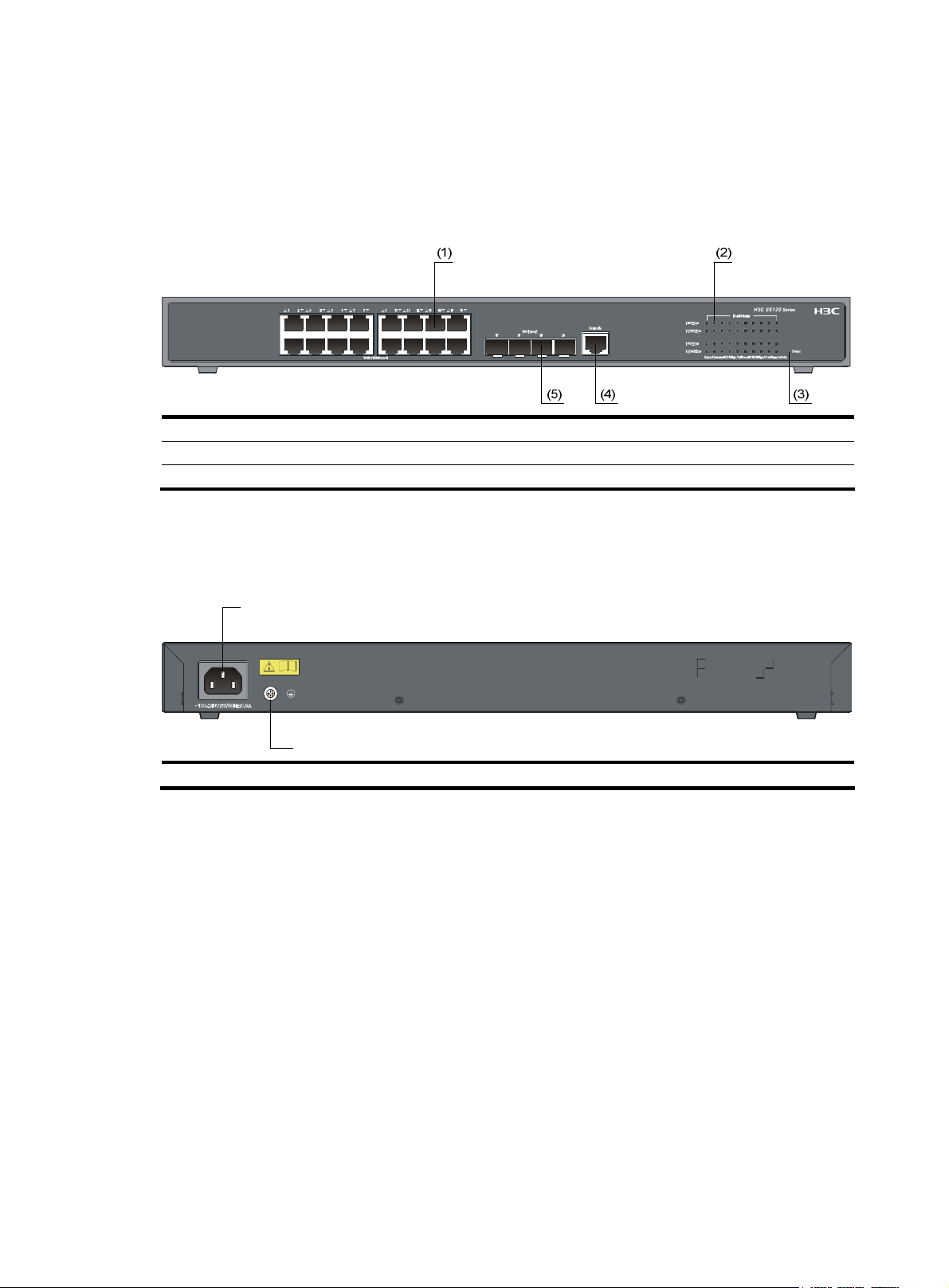
Figure 1 S5120-9P-SI front panel
(1) 10/100/1000Base-T auto-sensing Ethernet port (2) Port status LED
(3) Power LED (Power) (4) Console port
(5) 1000Base-X SFP interface
NOTE:
10/100/1000Base-T autosensing Ethernet ports on the S5120-SI Switch Series are numbered from top to
bottom and left to right as Port 1, Port 2, Port 3, and so on.
Rear panel
Figure 2 S5120-9P-SI rear panel
(1) AC receptacle (2) Grounding screw
Power supply system
AC power input:
Rated voltage range: 100 VAC to 240 VAC, 50 Hz or 60 Hz
Input voltage range: 90 VAC to 264 VAC, 47 Hz or 63 Hz
Cooling system
The S5120-9P-SI adopts a noise-free and fanless design, and uses natural heat dissipation.
3
Page 12
S5120-20P-SI
Front panel
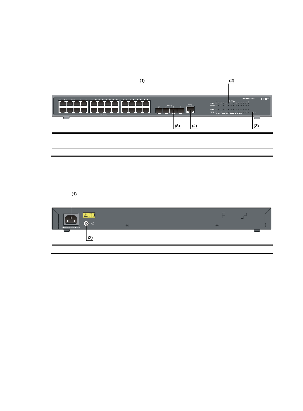
Figure 3 S5120-20P-SI front panel
(1) 10/100/1000Base-T auto-sensing Ethernet port (2) Port status LED
(3) Power LED (Power) (4) Console port
(5) 1000Base-X SFP interface
Rear panel
Figure 4 S5120-20P-SI rear panel
(1)
(2)
(1) AC receptacle (2) Grounding screw
Power supply system
AC power input:
Rated voltage range: 100 VAC to 240 VAC, 50 Hz or 60 Hz
Input voltage range: 90 VAC to 264 VAC, 47 Hz or 63 Hz
Cooling system
The S5120-20P-SI is equipped with one fan for heat dissipation
4
Page 13
S5120-28P-SI
Front panel
Figure 5 S5120-28P-SI front panel
(1) 10/100/1000Base-T auto-sensing Ethernet port (2) Port status LED
(3) Power LED (Power) (4) Console port
(5) 1000Base-X SFP interface
Rear panel
Figure 6 S5120-28P-SI rear panel
(1) AC receptacle (2) Grounding screw
Power supply system
AC power input:
Rated voltage range: 100 VAC to 240 VAC, 50 Hz or 60 Hz
Input voltage range: 90 VAC to 264 VAC, 47 Hz or 63 Hz
Cooling system
The S5120-28P-SI is equipped with one fan for heat dissipation.
5
Page 14

S5120-52P-SI
Front panel
Figure 7 S5120-52P-SI front panel
(1) 10/100/1000Base-T auto-sensing Ethernet port
(2) 10/100/1000Base-T auto-sensing Ethernet port status LED
(3) Console port (4) Power LED (Power)
(5) 1000Base-X SFP interface (6) 1000Base-X SFP interface status LED
Rear panel
Figure 8 S5120-52P-SI rear panel
(1)
(2)
(1) AC receptacle (2) Grounding screw
Power supply system
AC power input:
Rated voltage range: 100 VAC to 240 VAC, 50 Hz or 60 Hz
Input voltage range: 90 VAC to 264 VAC, 47 Hz or 63 Hz
Cooling system
The S5120-52P-SI is equipped with one fan for heat dissipation.
6
Page 15

S5120-9P-HPWR-SI
Front panel
Figure 9 S5120-9P-HPWR-SI front panel
(1) 10/100/1000Base-T auto-sensing Ethernet port (2) Port mode LED
(3) Port status LED (4) Power LED (Power)
(5) Port status LED mode switching button (6) Console port Port
(7) 1000Base-X SFP interface
Rear panel
Figure 10 S5120-9P-HPWR-SI rear panel
(1) AC receptacle (2) Grounding screw
Power supply system
AC power input:
Rated voltage range: 100 VAC to 240 VAC, 50 Hz or 60 Hz
Input voltage range: 90 VAC to 264 VAC, 47 Hz or 63 Hz
Cooling system
The H3C S5120-9P-HPWR-SI is equipped with three fans for heat dissipation.
7
Page 16
S5120-28P-PWR-SI
Front panel
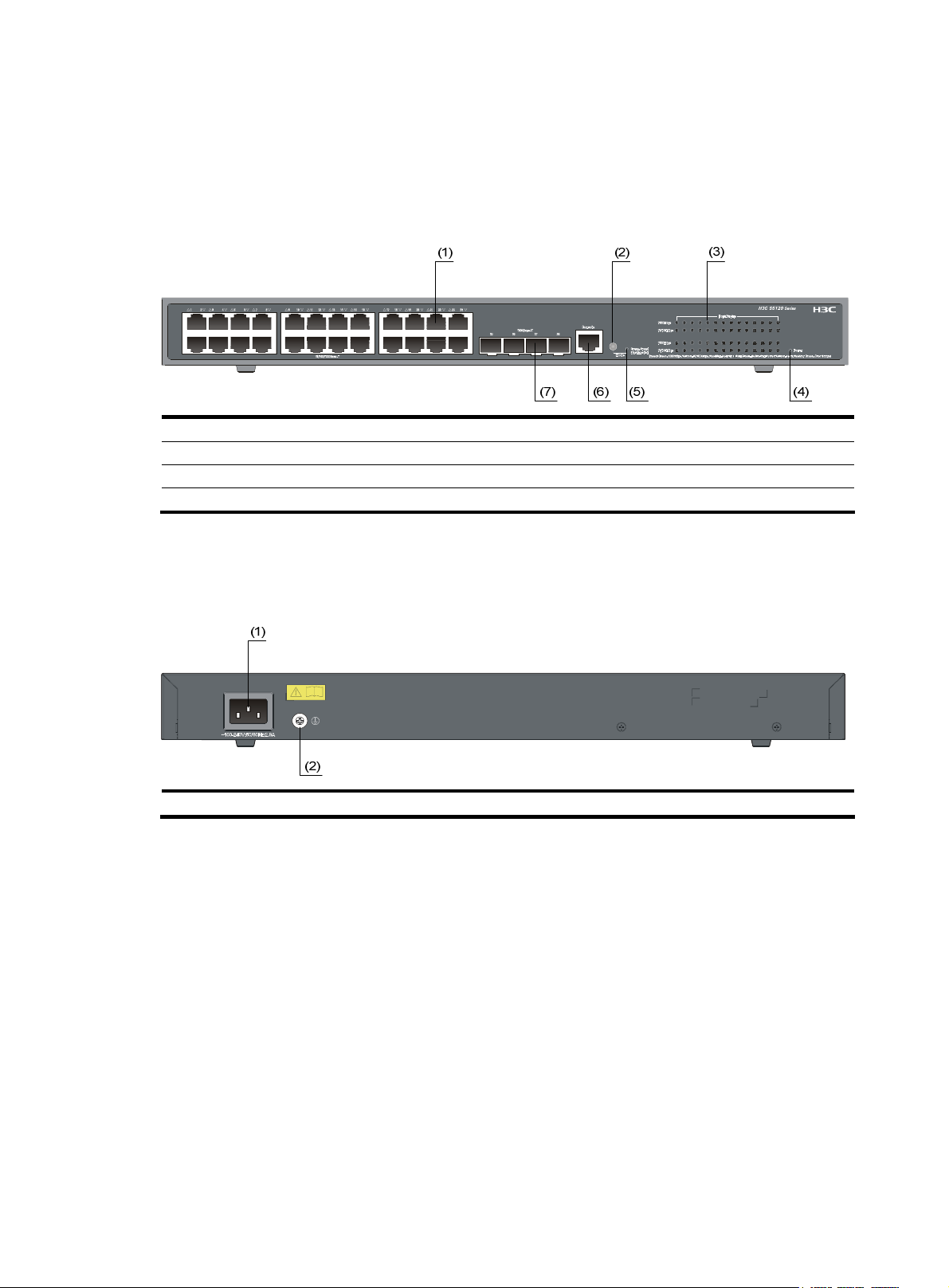
Figure 11 S5120-28P-PWR-SI front panel
(1) 10/100/1000Base-T auto-sensing Ethernet port (2) Port status LED mode switching button
(3) Port status LED (4) Power LED (Power)
(5) Port mode LED (6) Console port Port
(7) 1000Base-X SFP interface
Rear panel
Figure 12 S5120-28P-PWR-SI rear panel
(1) AC receptacle (2) Grounding screw
Power supply system
AC power input:
Rated voltage range: 100 VAC to 240 VAC, 50 Hz or 60 Hz
Input voltage range: 90 VAC to 264 VAC, 47 Hz or 63 Hz
Cooling system
The H3C S5120-28P-PWR-SI is equipped with three fans for heat dissipation.
8
Page 17
S5120-28P-HPWR-SI
Front panel
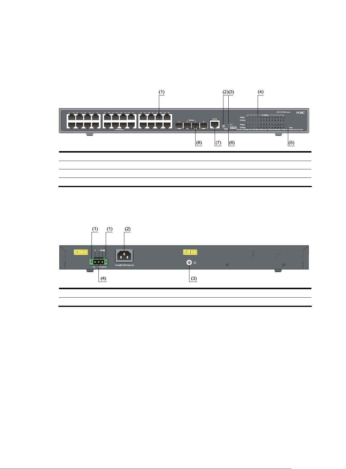
Figure 13 S5120-28P-HPWR-SI front panel
(1) 10/100/1000Base-T auto-sensing Ethernet port (2) Port status LED mode switching button
(3) RPS status LED (RPS) (4) Port status LED
(5) Power LED (Power) (6) Port mode LED
(7) Console port (8) Port 1000Base-X SFP interface
Rear panel
Figure 14 S5120-28P-HPWR-SI rear panel
(1) Screw hole of the plug (2) AC receptacle
(3) Grounding screw (4) DC power receptacle
Power supply system
The H3C S5120-28P-HPWR-SI can adopt AC power input, or DC power input, or both to provide backup
• AC power input:
Rated voltage range: 100 VAC to 240 VAC, 50 Hz or 60 Hz
Input voltage range: 90 VAC to 264 VAC, 47 Hz or 63 Hz
• DC power input
Rated voltage range: –52 VDC to –55 VDC
9
Page 18

CAUTION:
Only the RPS recommended by H3C can be used for the H3C S5120-28P-HPWR-SI. The –48 VDC
power supply in the equipment room cannot be used directly. Otherwise, the device may be
damaged.
Cooling system
The H3C S5120-28P-HPWR-SI is equipped with six fans for heat dissipation.
Ports
Console port
Each S5120-SI series provides one console port on the front panel.
Table 3 Console port specifications
Item Specification
Connector type
Compliant standard
Transmission baud rate 9600 bps to 115200 bps (defaulting to 9600 bps)
RJ-45
EIA/TIA-232
• It can be connected to an ASCII terminal.
Service
• It can be connected to a serial port of a local or remote (through a pair
of modems) PC running terminal emulation program.
10/100/1000Base-T Ethernet port
Each S5120-SI series provides 10/100/1000Base-T Ethernet ports on its front panel. Quantity of Ethernet
ports varies with the device model. For more information, see
Table 4 S5120-SI series 10/100/1000Base-T Ethernet port specifications
Item Specification
Connector type
Interface speed and operating
mode
RJ-45
• 10 Mbps, full duplex
• 100 Mbps, full duplex
• 1000 Mbps, full duplex
• MDI/MDI-X, auto-sensing
Table 1.
Max transmission distance
Transmission medium
Standard
100 m (328.1 ft.)
Category-5 unshielded twisted pair cable
IEEE 802.3i, IEEE 802.3u, IEEE 802.3ab
10
Page 19

g
t
e
1000Base-X SFP interface
Each S5120-SI series provides one or four 1000Base-X SFP interfaces on its front panel. You can select
the GE SFP transceiver modules described in
Table 5 Transceivers supported by the S5120-SI series 1000Base-X SFP interfaces
Transceiver
type
Transceiver module
Table 5.
Central
wavelength
Connector Fiber
Max
transmiss
ion
distance
GE SFP
transceiver
module
SFP-GE-SX-MM850-A 850 nm
SFP-GE-LX-SM1310-A
1310 nm
SFP-GE-LH40-SM1310
SFP-GE-LH40-SM1550
1550 nm
SFP-GE-LH70-SM1550
SFP-GE-LX-SM1310-BIDI*
SFP-GE-LX-SM1490-BIDI*
TX: 1310
RX: 1490
TX: 1490
RX: 1310
LC
LC
50/125 m
multimode
optical fiber
62.5/125 m
multimode
optical fiber
9/125 m
single mode
optical fiber
9/125 m
single mode
optical fiber
550 m
(0.34
miles)
275 m
(0.17
miles)
10 km
(6.21
miles)
40 km
(24.86
miles)
40 km
(24.86
miles)
70 km
(43.50
miles)
10 km
(6.21
miles)
SFP-GE-T — RJ-45
* SFP-GE-LX-SM1310-BIDI and SFP-GE-LX-SM1490-BIDI must be used in pairs.
NOTE:
• H3C recommends you to use SFP transceiver modules of H3C on the S5120-SI series.
• The SFP transceiver modules available for this switch series are subject to chan
up-to-date list of SFP transceiver modules, consult your H3C sales representative or technical support
engineer.
• For the SFP transceiver module specifications, see the
Modules Manual
.
11
H3C Low End Series Ethernet Switches Pluggabl
Twisted pair
cable
e over time. For the mos
100 m
(328.08
ft)
Page 20

LEDs
Table 6 LEDs
LED Device support Description
Power LED All series See “Power LED.”
RPS status LED S5120-28P-HPWR-SI See “RPS status LED.”
Port mode LED
10/100/1000Base-T
auto-sensing Ethernet port
status LED
1000Base-X SFP interface
status LED
Power LED
The power LED indicates the operation status of the switch.
Table 7 Description of the power LED
LED Status Description
Power
S5120-9P-HPWR-SI,
S5120-28P-PWR-SI, and
S5120-28P-HPWR-SI
All series
All series See “
Solid green The switch functions properly.
Blinking green (1 Hz)
Blinking green (3 Hz) The POST has failed or another fatal error has been detected.
The system is performing power-on self test (POST) or
downloading software.
See “Port mode LED.”
See “
10/100/1000Base-T auto-sensing
Ethernet port status LED.”
1000Base-X SFP interface status LED.”
RPS status LED
The H3C S5120-28P-HPWR-SI provides an RPS status LED on its front panel, indicating the working status
of the RPS of the switch.
Table 8 Description of the RPS status LED
LED Status Description
RPS
Port mode LED
The port mode LED on the S5120-9P-HPWR-SI, S5120-28P-PWR-SI, and S5120-28P-HPWR-SI can display
the working status of a port for you to obtain more device information. You can use the port mode
switching button to change the status of the port mode LED.
Off The switch has been powered off.
Solid green The RPS DC input is normal.
Off The RPS unit is not connected or the RPS DC input is abnormal.
12
Page 21

Table 9 Port mode LED description
LED Status Description
Mode
Solid green Indicates port rate.
Blinking green (1 Hz) Indicates port PoE power supply.
10/100/1000Base-T auto-sensing Ethernet port status LED
NOTE:
• Each port of the S5120-52P-SI has a bi-color LED indicating its status. Each port of other models of the
S5120-SI Switch Series has two LEDs, with only one in the ON state at a time.
• Fo r e a c h p o r t of th e S 5120 - 9 P- H PW R - S I, S 512 0 -2 8 P- P W R- S I , a n d S 512 0 -28 P- H PW R- S I, t h e p o r t m o d e
LED and the status LED together indicate the port operation status.
Table 10 10/100/1000Base-T auto-sensing Ethernet port LEDs description
Switch model
Port mode
LED
Ethernet port status LED Meaning
The port operates at a rate of 1000
Mbps.
Data is being transmitted or received at
1000 Mbps.
Green
On
Fast blinking
S5120-9P-SI
S5120-20P-SI
S5120-28P-SI
S5120-52P-SI —
S5120-9P-HPWR-SI
S5120-28P-PWR-SI
S5120-28P-HPWR-SI
—
Solid
green (rate
mode)
Yellow
Green
Yellow
Green
Off
On
Fast blinking
Off
On
Fast blinking
On
Fast blinking
Off The port is not up.
On
Fast blinking
The port is not up or does not operate at
1000 Mbps.
The port operates at a rate of 10/100
Mbps.
Data is being transmitted or received at
10/100 Mbps.
The port is not up or does not operate at
10/100 Mbps.
The port operates at a rate of 1000
Mbps.
Data is transmitted or received at a rate of
1000 Mbps.
The port operates at a rate of 10/100
Mbps.
Data is transmitted or received at a rate of
10/100 Mbps.
The port operates at a rate of 1000
Mbps.
Data is transmitted or received at a rate of
1000 Mbps.
Off
13
The port is not up or does not operate at
1000 Mbps.
Page 22

Switch model
Port mode
LED
Blinking
green (PoE
mode)
Ethernet port status LED Meaning
The port operates at a rate of 10/100
Mbps.
Data is transmitted or received at a rate of
10/100 Mbps.
The port is not up or does not operate at
10/100 Mbps.
Power consumption of the device
attached to the port exceeds the upper
limit of the power supply consumption of
the port, or the available power of the
switch is not enough for power supply of
the port.
No PoE power supply is provided on the
port.
The device connected to the interface is
not a PD device or a PoE failure occurs
No PoE power supply is provided on the
port or PoE power supply is normal.
Yellow
Green
Yellow
On
Fast blinking
Off
On PoE power supply is normal.
Blinking at 3
Hz
Off
On
Off
1000Base-X SFP interface status LED
NOTE:
For the S5120-9P-HPWR-SI, S5120-28P-PWR-SI, and S5120-28P-HPWR-SI, the port mode switching
button does not take effect for the 1000Base-X SFP interface LEDs.
Table 11 1000Base-X SFP interface status LEDs description
SFP interface status LED Meaning
Solid green
Blinking green The LED is fast flashing when data is being received on the port.
Off No link is present on the port.
The port operates at a rate of 1000 Mbps
The port is transmitting data at 1000 Mbps
14
Page 23

Preparing for installation
Safety precautions
To avoid any device impairment and bodily injury caused by improper use, observe these rules:
• Before cleaning the switch, unplug the power cord of the switch first. Do not clean the switch with
wet cloth or liquid.
• Do not place the switch near water or in a damp environment. Prevent water or moisture from
entering the switch chassis.
• Do not place the switch on an unstable case or desk. The switch might be damaged severely in case
of a fall.
• Ensure proper ventilation of the equipment room and keep the ventilation vents of the switch free of
obstruction.
• Connect the yellow-green protection grounding cable before power-on.
• Make sure that the operating voltage is as required.
• Do not open the chassis to avoid electrical shocks when the switch is operating or just when the
switch is powered off.
Examining the installation site
The S512 0-SI Switch Series must be used indoors. You can mount the switch in a rack or on a work bench,
but make sure:
• Adequate clearance is reserved at the air inlet/exhaust vents for ventilation.
• The rack or workbench has a good ventilation system.
• The rack is sturdy enough to support the switch and its accessories.
• The rack or workbench is well grounded.
To ensure normal operation and long service life of your switch, install it in an environment that meets the
requirements described in the following subsections.
Temperature/humidity
You must maintain a proper temperature and humidity in the equipment room. Long-term high humidity
may lead to bad insulation, electricity leakage, mechanical property changes, and metal corrosion.
However, if the relative humidity is too low, captive screws may become loose as the result of contraction
of insulation washers and static electricity may be produced in a dry environment to jeopardize the
circuits on the device. A high temperature is the most undesirable condition, because it accelerates the
aging of insulation materials and thus significantly lowers reliability and service life of the switch.
For the temperature and humidity requirements of different models, see
overview”.
15
Table 1 in the chapter “Product
Page 24

Cleanness
Dust is a hazard to the operating safety of your device. The dust accumulated on the chassis can be
adsorbed by static electricity and result in poor contact of metal connectors or metal contact points.
Especially when the indoor relative humidity is low, electrostatic adsorption is more likely to happen. This
can not only shorten the service life of your device but also cause communications failures. The following
table lists the dust concentration limit.
Table 12 Dust concentration limit in the equipment room
Substance Concentration limit (particles/m
Dust
Note: The dust diameter is greater than or equal to 5 m.
3 x 10⁴ (no visible dust on the tabletop over three days)
Besides dust, there are rigorous limits on the content of harmful substances in the air that can accelerate
the corrosion and aging of metals, such as chloride, acid, and sulfide in the equipment room. The
equipment room must be protected against ingression of harmful gases such as SO
For specific requirements, see the following table.
Table 13 Harmful gas limits in the equipment room
Gas Maximum concentration (mg/m
SO
2
H2S 0.006
NH3 0.05
Cl2 0.01
Electromagnetic susceptibility
The operation of your switch can be affected by external interferences, such as conducted emission by
capacitance coupling, inductance coupling, electromagnetic wave radiation, and common impedance
(including the grounding system) coupling, and leads (power cords, signaling cables and output wires).
To eliminate the interferences, pay attention to the following:
0.2
3
)
, H2S, NH3, and Cl2.
2
3
)
• The AC power system is a TN system, so use a single-phase three-wire power socket with a
protection earth (PE) to effectively filter interference from the power grid.
• Keep the switch far away from radio transmitting stations, radar stations, and high-frequency
devices.
• Use electromagnetic shielding, for example, shielded interface cables, when necessary.
• Route interface cables only indoors to prevent signal ports from getting damaged by over-voltage
or over-current caused by lightning strikes.
Laser safety
The S5120-SI Switch Series is a line of class 1 laser devices.
16
Page 25

CAUTION:
When an SFP module on an S5120-SI switch
laser light emitted from the optical fiber may hurt your eyes.
Installation tools
• Flat-blade screwdriver
• Phillips screwdriver
• ESD-preventive wrist strap
CAUTION:
No installation tools are shipped with the S5120-SI Switch Series.
is operating, do not stare into the optical port because the
17
Page 26

Installing the switch
CAUTION:
Keep the tamper-proof seal on a mounting screw on the chassis cover intact, and if you want to open the
chassis, contact the local agent of H3C for permission. Otherwise, H3C shall not be liable for any
consequence caused thereby.
Installation flow
Figure 15 Installation flow
18
Page 27

Installing the switch into a 19-inch rack by using mounting brackets
The S5120-SI Switch Series is shipped with a pair of mounting brackets to fix and support the switch.
Figure 16 shows how to install an S5120-SI into a 19-inch rack.
Figure 16 Install an S5120-SI into a 19-inch rack
Introduction to mounting brackets
Table 14 Mounting brackets for the S5120-SI Switch Series
Model
S5120-20P-SI
S5120-28P-SI
S5120-9P-SI Optional
S5120-9P-HPWR-SI Optional
S5120-52P-SI
S5120-28P-PWR-SI
S5120-28P-HPWR-SI
Mounting
brackets
Provided
by default
Provided
by default
Appearance Mounting position Description
See callout A in
Figure 17
See callout B in
Figure 17
See callout D in
Figure 17
See callout C in
Figure 17
Front or rear part of the
chassis’s side
Front or rear part of the
chassis’s side
Front or rear part of the
chassis’s side
Front or rear part of the
chassis’s side
Front, center, or rear part of
the chassis’s side
Front, center, or rear part of
the chassis’s side
See Figure 18 and
Figure 19
Figure 20 and
See
Figure 21
See Figure 22 and
Figure 23
See
Figure 24 and
Figure 26
See Figure 24,
Figure 25, and
Figure 26
19
Page 28

Figure 17 Mounting brackets
(1)
(1)
(A) (B)
(2)
(2)
(1)
(2)
(C)
(1)
(D)
(2)
(1) Screw hole used to fix the mounting bracket to the rack (with an M6 screw)
(2) Screw hole used to fix the switch to the mounting bracket
Attaching the mounting brackets to a switch
CAUTION:
The installation of actual mounting brackets varies with devices.
As shown in Table 14, the mounting brackets can be attached to a switch for front, center, or rear
mounting. You can choose a proper position according to the actual requirements.
Follow these steps to install a mounting bracket to the chassis:
Step1 Align the mounting holes of the bracket with the holes of the chassis, as shown in Figure 18.
Step2 Fasten the screws.
Figure 18 Install a mounting bracket on the chassis (A)
(1) Front panel
20
Page 29

Figure 19 Install a mounting bracket on the chassis (B)
(1)
(1) Front panel
Figure 20 Install a mounting bracket on the chassis (C)
(1) Front panel
Figure 21 Install a mounting bracket on the chassis (D)
(1) Front panel
Figure 22 Install a mounting bracket on the chassis (E)
(1) Front panel
21
Page 30

Figure 23 Install a mounting bracket on the chassis (F)
(1)
(1) Front panel
Figure 24 Install a mounting bracket on the chassis (G)
(1) Front panel
Figure 25 Install a mounting bracket on the chassis (H)
(1) Front panel
Figure 26 Install a mounting bracket on the chassis (I)
(1) Front panel
Mounting the switch to a rack
Step1 Wear an ESD-preventive wrist strap and make sure the rack is well grounded and is firm enough to
support the switch and cables.
22
Page 31

Step2 Locate the positions for installing cage nuts on the rack post, and use a marker to mark the positions.
Step3 Install cage nuts at the marked positions.
Step4 Attach the mounting brackets to the switch. For more information, see “Attaching the mounting brackets
to a switch.”
Step5 Use one person to support the bottom of the switch and gently place the switch on the rack to a proper
location.
Step6 Use another person to fix the mounting brackets with screws (anti-rust screws with cage nuts prepared by
yourself) to the square holes of the rack to install the switch to the rack horizontally, as shown in
27 or
Figure 28.
NOTE:
Figure
The method for installing the S5120-SI Switch Series into a rack is similar. For how to install the
a rack by using mounting brackets, see
position of the mounting brackets as described in
Figure 27 or Figure 28 according to the model and mounting
Table 14.
Figure 27 Mount the S5120-20P-SI to a rack
(1)
前(两孔)
(2)
switch to
(1) Front panel (2) Rear panel
23
Page 32

g
Figure 28 Mount the S5120-28P-PWR-SI to a rack
(1)
(1) Front panel (2) Rear panel
NOTE:
If support trays are provided on the rack, you can mount the switch to the rack with mountin
brackets and
trays. To do so, put the switch on the support tray and slide the switch to an appropriate location, and then
fix the mounting brackets.
Mounting the switch on a workbench
In many cases, standard 19-inch racks are not available. Therefore, switches are often placed on clean
workbenches. To place the switch on a workbench, follow these steps:
24
Page 33

Step1 Place the switch with bottom up carefully, and then clean the round holes on the chassis bottom with dry
cloth.
Step2 Attach the rubber feet to the four round holes on the chassis bottom.
Step3 Place the switch with upside up on the workbench.
During the operation, you simply need to follow these guidelines:
• Make sure that the workbench is flat and sturdy.
• Ensure good ventilation and a space of 10 cm (3.94 in) around the chassis for heat dissipation.
• Avoid heavy objects on the switch.
Mounting the switch to a wall
You can mount the S5120-9P-SI, and S5120-9P-HPWR-SI on concrete or wood walls.
Table 15 Models supporting wall mounting
Model Hole distance
S5120-9P-SI 98.5 mm (3.88 in)
S5120-9P-HPWR-SI 174.0 mm (6.85 in)
Introduction to expansion screws
NOTE:
Wall mounting tools such as expansion screws are not provided with the S5120-SI Switch Series.
An expansion screw comprises an anchor kit and a screw, as shown in Figure 29. Use expansion screws
with an outer diameter of no less than 4 mm (0.16 in) for wall mounting.
Figure 29 Expansion screw
Installation procedure
Follow these steps to mount the switch to a wall:
Step1 As shown in Figure 30, drill two holes 5 mm (0.20 in) across in the wall on the same horizontal line, with
a distance of X mm.
25
Page 34

NOTE:
Figure 30 Hole distance
Xmm
• The distance X between holes varies with devices. For specific distances, see
Table 15.
• Drill two holes according to the sizes of anchor kits and screws so that anchor kits could go into the
holes, only the edges could remain outside the wall, and the screws could be fixed on the wall tightly.
Step2 Insert anchor kits into the holes and keep only the edges outside the wall, as shown in Figure 31.
Step3 Drive screws into the anchor kits, keeping the inside of screw head at least 1.5 mm (0.06 in) away from
the edge of the anchor kit so that the switch could hang on the screws securely.
Figure 31 Install the expansion screws
NOTE:
When you drive the screw to the anchor kit, the front end
of the anchor kit expands to press against the
hole so that the screw can be fixed on the wall.
Step4 Align the two installation holes at the bottom of the switch with these two screws to hang the switch, as
shown in
Figure 32.
26
Page 35

g
Figure 32 Wall mounting
(1) Installation hole
CAUTION:
When mountin
ventilation holes vertical to the ground.
the switch, keep the Ethernet ports of the switch facing downwards and the two sides with
Mounting the switch through magnet mounting
The S5120-9P-SI and S5120-9P-HPWR-SI support magnet mounting.
Introduction to magnetic mounting accessories
A set of magnetic mounting accessories comprises one permanent magnet and one M3*6 countersunk
head screw, as shown in
switch.
Figure 33 Magnet and countersunk head screw
(1) Permanent magnet (2) M3*6 countersunk head screw
Figure 33. Four sets of magnetic mounting accessories are needed for each
Installation procedure
Follow these steps to complete magnet mounting:
Step1 As shown in Figure 34, use a Phillips screwdriver to pass the countersunk head screw through the round
hole at the center of the permanent magnet, fasten it to a blind nut in the dent of the switch bottom, and
make sure that the permanent magnet and the switch are fastened reliably.
27
Page 36

t
g
y
NOTE:
• Remove the cushion, if any, from the dent before installation.
• To ensure the firmness of installation, be sure to use four permanent magnets to secure each switch.
Step2 Attach the magnet-mounted switch to the specified location. Do not get your fingers stuck between.
Figure 34 Magnet mounting
(1)
(2)
(3)
(1) Blind nut in the dent of the switch bottom (2) Permanent magnet
(3) M3*6 countersunk head screw
CAUTION:
• Apply magnet mounting to only the above two models. Otherwise, a falloff or mis-operation may occur.
• Select the installation location carefully. In the case of poor surface, magnet mounting may not be
reliable.
• Put the switch at a stable place free from vibrations or shocks. Otherwise, personal injuries or equipmen
damage may occur.
• Avoid installing the switch at a high place because bodily injuries or equipment dama
e may occur in
case of a falloff.
• Avoid frequently moving the desk-mounted switch because such movements may damage the surface
coating.
• To install the device vertically, keep the front panel of the switch facing downwards and the two sides
with ventilation holes vertical to the ground.
• Make sure that the weight of external cables does not bring about a falloff, which may result in bodil
injuries or equipment damage.
• Keep magnetic cards away from magnets to avoid erasure of any information.
• Keep computers and monitors that are easily influenced by magnetic fields away from magnets.
Otherwise, faults may occur to these electronic devices.
28
Page 37

Connecting the grounding cable
CAUTION:
• Correctly connecting the switch grounding cable is crucial to the lightning protection and
electromagnetic susceptibility (EMS) of a switch.
• The power interface and grounding terminals in this section are for illustration only.
The power input end of the switch is connected with a noise filter, whose central ground is directly
connected to the chassis, forming the so-called chassis ground (commonly known as PGND). This chassis
ground must be securely connected to the earth so that the faradism and leakage electricity can be safely
released to the earth, enhancing the EMS capability of the switch.
When a grounding strip is available
When a grounding strip is available at the installation site, attach one end of the yellow-green grounding
cable of the switch to the grounding screw on the grounding strip (the grounding screw and the
grounding hole are on the rear panel of the switch and are marked with a grounding sign). To do this,
follow these steps:
Step1 Remove the grounding screw from the rear panel of the switch chassis.
Step2 Put the supplied OT terminal of the grounding cable on the grounding screw.
Step3 Fasten the grounding screw, which is attached with the OT terminal of the grounding cable, into the
grounding screw hole with a screwdriver.
Figure 35 Connect the grounding cable to the grounding hole of switch
(1) Rear panel of the switch (2) Grounding sign
(3) Grounding hole (4) OT terminal
(5) Grounding cable (6) Grounding screw
To attach the other end of the grounding cable to the grounding strip in the equipment room, follow these
steps:
29
Page 38

g
g
Step4 Cut the grounding cable to a proper length according to the distance between the switch and the
grounding strip.
Step5 Peel 5 mm (0.20 in) of insulation sheath, and then insert the naked metal part through the insulation
covering into the end of the OT terminal.
Step6 Secure the metal part of the cable to the OT terminal with a crimper, and then cover it with the insulation
covering. Then heat the insulation covering with a blower to make it completely cover the metal part.
Step7 Connect the OT terminal to the grounding pole of the grounding strip, and then fasten it with a hex nut.
Figure 36 Connect the grounding cable to the grounding strip
(1) Grounding post (2) Grounding strip
(3) Grounding cable (4) Hex nut
CAUTION:
• Only the grounding cables supplied with the S5120-28P-HPWR-SI and S5120-28P-PWR-SI provide OT
terminals at the ends connecting the grounding strip. For other switch models, prepare proper OT
terminals by yourself.
• The fire main and lightning rod of a building are not suitable for grounding the switch. The
cable of the switch should be connected to the grounding device for the equipment room.
Where a grounding conductor can be buried
When there is no grounding strip, but an area with exposed earth is available nearby where a
grounding conductor can be buried, hammer a 0.5 m (1.64 ft) or longer angle iron or steel tube into the
earth. The angle iron should have a dimension no less than 50 × 50 × 5 mm (1.97 × 1.97 × 0.20 in) and
the steel tube should have a wall thickness no less than 3.5 mm (0.14 in) and be zinc-coated. Weld the
yellow-green grounding cable to the angel iron or steel tube and treat the joint for corrosion protection.
roundin
30
Page 39

Figure 37 Ground the switch by burying the grounding conductor into the earth
(1) Grounding screw (2) Grounding cable (3) Earth
(4) Joint (5) Grounding conductor (6) Switch rear panel
In other installation sites
When the switch is AC-powered
For an AC-powered switch, if neither of the above-mentioned two conditions is available, ground the
switch throug h the PE wire of th e AC power supply. Make sure th e PE wire is we ll con nected to th e ground
at the power distribution room or AC transformer side, the switch PE terminal and the PE wire are well
connected, and the three-wire input cable of the grounding cable is used for the power supply cable. If
the PE wire of the AC power supply is not grounded at the power distribution room or AC transformer side,
report the problem and make reconstructions.
Figure 38 Ground through an AC power PE wire
(1) Three-wire AC power input cable (2) Switch rear panel
NOTE:
Use the grounding cable provided with the switch to connect the grounding strip in the equipment room.
Otherwise, the grounding effect may not be ensured, which easily causes damage to the switch.
31
Page 40

Connecting the power cord
Connecting an AC power cord
CAUTION:
Make sure that the grounding cable has been properly connected before powering on the switch.
The S5120-SI Switch Series uses an external AC power system for its power supply. Follow these steps to
connect an AC power cord:
Step1 Connect one end of the supplied grounding cable to the grounding screw on the rear panel of the
chassis and the other end to the ground as near as possible.
Step2 Insert one end of the AC power cord to the AC power receptacle on the rear panel of the chassis, as
shown in
Step3 Connect the other end of the power cord to a power source.
Figure 39 Connect the AC power cord (A)
Figure 39.
The S5120-9P-SI and S5120-9P-HPWR-SI provide a bail latch to fix the AC power cord. Follow these steps
to connect an AC power cord for these switches:
Step4 Insert the two ends of the bail latch to the slots at the two sides of the AC power receptacle. Then push
the bail latch upwards, as shown in
Step5 Inse rt on e end o f the AC p ower cord to the AC power rec eptacle, as shown in call out 1 i n Figure 41. Then
pull the bail latch downwards to secure the AC power cord, as shown in callout 2 in
Figure 40.
Figure 41.
Figure 40 Connect the AC power cord (B)
32
Page 41

Figure 41 Connect the AC power cord (C)
Connecting an RPS DC power cord
The S5120-28P-HPWR-SI also supports RPS DC power input with the input voltage ranging from –52 V to
–55 V. Follow these steps to install a DC power cord:
Step1 Connect one end of the supplied grounding cable to the grounding screw on the rear panel of the
chassis and the other end to the ground as near as possible.
Step2 Keep the upside of the DC RPS plug on top and plug it in the RPS DC receptacle (see callout 1 in Figure
42). (If you plug it with the upside down, the insertion is not smooth because of the specific structure
design of the RPS DC receptacle and the RPS plug.)
Step3 Use a flat-blade screwdriver to fix the two screws on the RPS plug clockwise to secure the plug to the RPS
DC receptacle (see callout 2 in
Step4 Connect the other end of the RPS DC power cord to the external RPS power supply system (–54 V/25 A
Figure 42).
output).
Step5 Check whether the RPS LED on the front panel of the switch is ON. If the LED is ON, it shows the power
cord is properly connected.
Figure 42 Connect an RPS DC power cord to the S5120-28P-HPWR-SI
CAUTION:
• Make sure that the grounding cable has been properly connected before powering on the switch.
• The length of the DC power cord must be less than 3 m (9.8 ft).
33
Page 42

Verifying the installation
Before powering on the switch, check that:
• There is enough space for heat dissipation around the switch, and the rack or workbench is stable.
• The grounding cable is connected.
• The selected power module matches that required by the switch.
• The power cords are properly connected.
• All the interface cables are cabled indoors. If there is any cable wired outdoors, verify that socket
strip with lightning protection and lightning arresters for network ports have been properly
connected.
34
Page 43

Initial power-on
Setting up the configuration environment
To set up the configuration environment, connect a terminal (a PC in this example) to the console port on
the switch with a console cable.
Figure 43 Network diagram for configuration environment setup
Connecting the console cable
Console cable
A console cable is an 8-core shielded cable. One end of the cable is a crimped RJ-45 connector, which
is connected to the console port of the switch, and the other end is a DB-9 female connector, which is
connected to the serial port on the console terminal, as shown below.
Figure 44 Console cable
Table 16 Console cable pinouts
RJ-45 Signal Direction DB-9
1 RTS
←
7
2 DTR
3 TXD
35
←
←
4
3
Page 44

RJ-45 Signal Direction DB-9
4 CD
5 GND -- 5
6 RXD
7 DSR
8 CTS
Connection procedure
To use the terminal to configure the switch, follow these steps to connect a terminal device to the switch
by using the console cable:
1. Plug the DB-9 female connector of the console cable to the serial port of the console terminal or PC.
2. Connect the RJ-45 connector of the console cable to the console port of the switch.
CAUTION:
Pay attention to the mark on the console port and be sure to plug the connector to the correct port.
→
→
→
→
1
2
6
8
NOTE:
• When connecting a PC to a powered-on switch, H3C recommends you to connect the DB-9 connector
of the console cable to the PC before connecting the RJ-45 connector to the switch.
• When disconnecting a PC from a powered-on switch, H3C recommends you to disconnect the DB-9
connector of the console cable from the PC after disconnecting the RJ-45 connector from the switch.
Setting terminal parameters
When setting up the configuration environment through the console port, the terminal or PC can use the
terminal emulation program to communicate with the switch. You can run the HyperTerminal of the
Windows operating system to connect to other PCs, network devices, and Telnet sites. For detailed
information and the use of the HyperTerminal, see the HyperTerminal Help documentation in Help and
Support Center on the PC running the Windows operating system.
In the following configuration procedure, Windows XP HyperTerminal is used to communicate with the
switch.
1. Start the PC and run the terminal emulation program.
2. Set terminal parameters as follows:
• Bits per second: 9,600
• Data bits: 8
• Parity: None
• Stop bits: 1
• Flow control: None
• Emulation: VT100
The specific procedure is as follows:
36
Page 45

Step1 Select Start > All Programs > Accessories > Communications > HyperTerminal to enter the
HyperTerminal window. The Connection Description dialog box appears, as shown below.
Figure 45 Connection description of the HyperTerminal
Step2 Type the name of the new connection in the Name text box and click OK. The following dialog box
appears. Select the serial port to be used from the Connect using drop-down list.
Figure 46 Set the serial port used by the HyperTerminal connection
Step3 Click OK after selecting a serial port. The following dialog box appears. Set Bits per second to 9600,
Data bits to 8, Parity to None, Stop bits to 1, and Flow control to None.
37
Page 46

Figure 47 Set the serial port parameters
Step4 Click OK after setting the serial port parameters and the system enters the HyperTerminal window shown
below.
Figure 48 HyperTerminal window
38
Page 47

Step5 Click Properties in the HyperTerminal window to enter the Switch Properties dialog box. Click the
Settings tab, set the emulation to VT100, and then click OK.
Figure 49 Set terminal emulation in Switch Properties dialog box
Booting the switch
Checking before power-on
Before powering on the switch, verify that:
• The power cord is properly connected.
• The power supply voltage meets the requirement of the switch.
• The console cable is properly connected; the terminal or PC used for configuration has been started;
and the configuration parameters have been set.
Powering on the switch
The S5120-SI switches have the same Boot ROM display style. This document uses the Boot ROM output
information on the S5120-28P-SI as an example:
Starting......
************************************************************************
* *
* H3C S5120-28P-SI BOOTROM, Version 135 *
39
Page 48

g
NOTE:
* *
************************************************************************
Copyright (c) 2004-2011 Hangzhou H3C Technologies Co., Ltd.
Creation Date : Jan 9 2011
CPU Type : ARM926
CPU L1 Cache : 32KB
CPU Clock Speed : 333MHz
Memory Type : DDR2 SDRAM
Memory Size : 128MB
Flash Size : 128MB
CPLD Version : 001
PCB Version : Ver.B
Mac Address : 000ef2005120
Press Ctrl-B to enter Extended Boot menu...1
The last line asks whether you want to enter the Boot ROM menu. The system waits for one second for
your response.
• The system has two startup modes: normal startup and fast startup. The normal startup mode requires a
little longer time than the fast startup mode because of more self-test operations.
• By default, the system starts up in fast mode and the waiting time here is one second. If you set the
startup mode to normal, the waiting time is five seconds. The following section describes the settin
of
the startup mode.
• If you press Ctrl + B within one second, the Boot ROM menu is displayed.
BOOT MENU
1. Download application file to flash
2. Select application file to boot
3. Display all files in flash
4. Delete file from flash
5. Modify BootRom password
6. Enter BootRom upgrade menu
7. Skip current system configuration
8. Set BootRom password recovery
9. Set switch startup mode
0. Reboot
Enter your choice(0-9):
Table 17 Description on the fields
Item Description
1. Download application file to flash Download the boot file to the flash memory
2. Select application file to boot Select the boot file to boot
3. Display all files in flash Display all files in the flash memory
40
Page 49

Item Description
4. Delete file from flash Delete files from the flash memory
5. Modify BootRom password Modify the Boot ROM password
6. Enter BootRom upgrade menu Enter the Boot ROM update menu
7. Skip current system configuration Skip the current configuration file (this configuration is valid once)
8. Set BootRom password recovery Restore the Boot ROM password
9. Set switch startup mode Set the startup mode of the switch
0. Reboot Restart the switch
• If you perform no operation or press a key other than Ctrl + B within one second, once the
remaining waiting time becomes zero, the system begins to automatically start up and the following
information is displayed:
Starting to get the main application file--flash:/S5120-CMW520-A1101.bin!......
.................................................................
The main application file is self-decompressing................................
...............................................................................
..............................Done!
System is starting...
User interface aux0 is available.
Press ENTER to get started.
The appearance of "Press ENTER to get started" indicates that the automatic startup of the switch is
complete.
Press Enter. The following prompt is displayed:
<H3C>
You can configure the switch now.
Changing the boot mode
By default, the system starts up in fast boot mode. If you want to change the boot mode to normal, press
Ctrl + B within one second to enter the Boot ROM menu showed below:
BOOT MENU
1. Download application file to flash
2. Select application file to boot
3. Display all files in flash
4. Delete file from flash
5. Modify BootRom password
6. Enter BootRom upgrade menu
7. Skip current system configuration
8. Set BootRom password recovery
9. Set switch startup mode
0. Reboot
Enter your choice(0-9):
41
Page 50

Enter 9. The system prompts you to change the startup mode:
The current mode is fast startup mode!
Are you sure you want to change it to full startup mode? Yes or No (Y/N):
Enter Y. The system displays the following information:
Setting...Done!
BOOT MENU
1. Download application file to flash
2. Select application file to boot
3. Display all files in flash
4. Delete file from flash
5. Modify BootRom password
6. Enter BootRom upgrade menu
7. Skip current system configuration
8. Set BootRom password recovery
9. Set switch startup mode
0. Reboot
Enter your choice(0-9):
Enter 0. The system reboots in normal startup mode and displays the following information:
Starting......
************************************************************************
* *
* H3C S5120-28P-SI BOOTROM, Version 135 *
* *
************************************************************************
Copyright (c) 2004-2011 Hangzhou H3C Technologies Co., Ltd.
Creation Date : Jan 9 2011
CPU Type : ARM926
CPU L1 Cache : 32KB
CPU Clock Speed : 333MHz
Memory Type : DDR2 SDRAM
Memory Size : 128MB
Flash Size : 128MB
CPLD Version : 001
PCB Version : Ver.B
Mac Address : 000ef2005120
Press Ctrl-B to enter Extended Boot menu...5
In normal startup mode, the waiting time here is five seconds. If you press Ctrl + B within five seconds, the
Boot ROM menu is displayed. If you perform no operation or press a key other than Ctrl + B within five
seconds, the system begins to automatically start up and the following information is displayed:
Starting to get the main application file--flash:/S5120-CMW520-A1101.bin!......
................................................................
The main application file is self-decompressing................................
...............................................................................
..............................Done!
System is starting...
Board checking..........................LS51LTSR
42
Page 51

g
NOTE:
SDRAM fast selftest..........................OK!
Flash fast selftest..........................OK!
CPLD selftest................................OK!
Switch chip selftest.........................OK!
PHY selftest.................................OK!
Please check leds......................FINISHED!
User interface aux0 is available.
Press ENTER to get started.
The appearance of "Press ENTER to get started" indicates that the automatic startup of the switch is
complete.
Press Enter. The following prompt is displayed:
<H3C>
You can configure the switch now.
The H3C series switches provide abundant command views. For more information about the confi
commands and command line interface (CLI), see
H3C S5120-SI Switch Series Command Reference
H3C S5120-SI Switch Series Configuration Guide
.
uration
and
43
Page 52

Loading software
Introduction
The S5120-SI Switch Series does not provide independent Boot ROM program but integrates it with the
application program in host software package with the extension name of .bin.
• Loading boot files: Download the host software package to the flash memory on the switch and set
the attribute (main, backup, or none) of the boot files.
• Upgrading the Boot ROM program: Use Boot ROM files in the host software package to upgrade
the Boot ROM program of the switch.
NOTE:
The entire Boot ROM program consists of the basic segment and extended segment.
• The basic segment is used for basic initialization of the system.
• The extended segment provides abundant human-computer interaction (HCI) functions and available
network interfaces. It can be used to upgrade the applications and boot the system.
Boot ROM program (stored together with application programs in the host software package with an
extension name of .bin) used for upgrade are complete Boot ROM program.
Approaches for loading boot files and configuration files
You can load boot files and configuration files of the switch through the Boot ROM menu or at the CLI.
Table 18 Approaches for loading boot files and configuration files of the switch
Approach Section
Loading files by using XMODEM through the console port
Loading files through the Boot ROM menu
Loading files at the CLI
Loading files by using TFTP through an Ethernet port
Loading files by using FTP through an Ethernet port
Loading files by using FTP
Loading files by using TFTP
Loading files through the Boot ROM menu
To load the Boot ROM and boot files through the Boot ROM menu, correctly connect a user terminal to
the switch by using a console cable.
Introduction to the Boot ROM menu
Starting......
44
Page 53

************************************************************************
* *
* H3C S5120-28P-SI BOOTROM, Version 135 *
* *
************************************************************************
Copyright (c) 2004-2011 Hangzhou H3C Technologies Co., Ltd.
Creation Date : Jan 9 2011
CPU Type : ARM926
CPU L1 Cache : 32KB
CPU Clock Speed : 333MHz
Memory Type : DDR2 SDRAM
Memory Size : 128MB
Flash Size : 128MB
CPLD Version : 001
PCB Version : Ver.B
Mac Address : 000ef2005120
Press Ctrl-B to enter Extended Boot menu...1
When the system displays “Press Ctrl-B to enter Extended Boot menu”, press Ctrl + B. Then, the following
prompt is displayed:
Please input BootRom password:
NOTE:
• By default, the system starts up in fast mode and the waiting time here is one second. If you set the
startup mode to normal, the waiting time is five seconds. For the setting of the startup mode, see
“
Changing the boot mode.”
• To enter the Boot ROM menu in fast mode, press Ctrl + B within one second when the system displays
“Press Ctrl-B to enter Boot Menu”. Otherwise, the system starts decompressing the boot files.
• To enter the Boot ROM menu after the boot files are decompressed, restart the switch.
Ente r th e Bo ot ROM password (th e in itia l pa ssword is nul l). Then the sys tem d isp lays th e Bo ot ROM menu.
BOOT MENU
1. Download application file to flash
2. Select application file to boot
3. Display all files in flash
4. Delete file from flash
5. Modify BootRom password
6. Enter BootRom upgrade menu
7. Skip current system configuration
8. Set BootRom password recovery
9. Set switch startup mode
0. Reboot
45
Page 54

Enter your choice(0-9):
The items in the Boot ROM menu are described in
Table 17.
NOTE:
• Currently, Boot ROM files are not provided separately by the S5120-SI Switch Series; instead, they are
stored together with boot files in the files with the name extension of .bin.
• The procedures for loading Boot ROM files and boot files are similar except that you need to select
different items (1 for loading boot files, and 6 for loading Boot ROM files) in the Boot ROM menu. This
document takes the loading of Boot ROM files as examples.
Loading files by using XMODEM through the console port
Introduction to XMODEM
XMODEM is a file transfer protocol widely used for its simplicity. XMODEM transfers files through the
console port, supporting data packets of 128 bytes. With respect to reliability, it supports checksum, CRC,
and the error packet retransmission mechanism. Normally, the maximum number of retransmission
attempts is 10.
XMODEM transfer is completed by receiving and sending programs together. Receiving program
initiates packet checking method negotiation by sending the negotiation character. If negotiation passes,
the sending program starts packet transfer. Upon receipt of a complete packet, the receiving program
checks it using the agreed-upon check method. If the check succeeds, the receiving program sends an
acknowledgement character; if the check fails, it sends a reject character. Upon receipt of the
acknowledgement, the sending program continues to send the next packet; upon receipt of the reject, it
retransmits the packet.
Loading a Boot ROM file
Complete the following tasks to load a Boot ROM file by using XMODEM through the console port. For
more information about the HyperTerminal, see the chapter “Initial power-on” (page
Task Remarks
Enter the Boot ROM update menu on the switch
Enter the protocol parameter setting menu
Configure the switch to download files by using
XMODEM
Set the download rate of the console port on the
switch
Change the rate of the serial port on the terminal
Establish a connection between the terminal and the
switch by using the changed rate
Uploading a boot file from the terminal to the switch
36).
Required
Log in to the switch through the HyperTerminal and
then configure the protocol used for loading files.
Required
Log in to the switch through the HyperTerminal and
then set the download rate of the console port on the
switch.
Optional
Set the baud rate of the serial port on the terminal to be
consistent with that of the console port on the switch.
Optional
Required
Transmit a file from the terminal to the switch by using
the changed connection rate.
46
Page 55

Task Remarks
Upgrading the Boot ROM file on the switch
Required
Upgrade the Boot ROM file on the switch.
Optional
Restoring the download rate to the default
Set the baud rate of the serial port on the terminal to be
consistent with the default rate of the console port on
the switch.
Restarting the switch to make the upgraded Boot ROM
file effective
Required
1. Enter the Boot ROM update menu on the switch
Enter the Boot ROM menu, and then enter 6 or press Ctrl + U after the system displays “Enter your
choice(0-9):” to enter the Boot ROM update menu.
Enter your choice(0-9): 6
1. Update full BootRom
2. Update extended BootRom
3. Update basic BootRom
0. Return to boot menu
Enter your choice(0-3):
Table 19 Description of the Boot ROM update menu
Item Description
1. Update full BootRom Upgrade the complete Boot ROM file
2. Update extended BootRom Upgrade the extended Boot ROM section
3. Update basic BootRom Upgrade the basic Boot ROM section
0. Return to boot menu Return to the Boot ROM menu
2. Enter the protocol parameter setting menu
After the system displays “Enter your choice(0 -3):”, enter 1 to enter the protocol parameter setting menu.
NOTE:
All the Boot ROM files to be loaded are complete Boot ROM files.
1. Set TFTP protocol parameter
2. Set FTP protocol parameter
3. Set XMODEM protocol parameter
0. Return to boot menu
Enter your choice(0-3):
Table 20 Description of the protocol parameter setting menu
Item Description
1. Set TFTP protocol parameter Set TFTP parameters
47
Page 56

Item Description
2. Set FTP protocol parameter Set FTP parameters
3. Set XMODEM protocol parameter Set XMODEM parameters
0. Return to boot menu Return to the Boot ROM menu
3. Configure the switch to download files by using XMODEM
Enter 3 to enter the download rate setting menu.
Please select your download baudrate:
1.* 9600
2. 19200
3. 38400
4. 57600
5. 115200
0. Return to boot menu
Enter your choice(0-5):
4. Set the download rate of the console port on the switch
Select an appropriate download rate. For example, if you select 115200 bps, that is, enter 5, the
following information is displayed:
Download baudrate is 115200 bps
Please change the terminal's baudrate to 115200 bps and select XMODEM protocol
Press enter key when ready
Now that the console communication baud rate of the switch has been changed to 115200 bps while
that of the terminal is still 9600 bps, the two sides cannot communicate with each other. According to the
prompt, you need to change the baud rate of the terminal to 115200 bps.
NOTE:
• Typically, the size of a .bin file is over 9 MB. Even at a baud rate of 115200 bps, the update takes tens
of minutes.
• If you select 9600 bps as the download rate, you can skip the step
Change the rate of the serial port
on the terminal.
5. Change the rate of the serial port on the terminal
To ensure communication between the terminal and the switch, the baud rate of the serial port on the
terminal should be consistent with that of the console port on the switch.
Step1 Select Call > Disconnect in the HyperTerminal window to disconnect the terminal from the switch.
Figure 50 Disconnect the terminal from the switch
48
Page 57

Step2 Select File > Properties. In the Properties dialog box, click Configure (as shown in Figure 51), and then
select 11 5 2 0 0 from the Bits per second drop-down list box (as shown in
Figure 52).
Figure 51 Properties dialog box
49
Page 58

Figure 52 Modify the baud rate
Step3 Select Call > Call to reestablish the connection.
Figure 53 Reestablish the connection
NOTE:
The new settings can take effect only after you reestablish the connection.
6. Establish a connection between the terminal and the switch by using the changed rate
Press Enter to reestablish the connection between the terminal and the switch and download the boot file
at 115200 bps. The following information is displayed:
Now please start transfer file with XMODEM protocol
If you want to exit, Press <Ctrl+X>
Loading ...CCCCCCCCCCCCC
NOTE:
Press Ctrl + X to quit downloading files; otherwise, proceed as follows.
7. Uploading a boot file from the terminal to the switch
50
Page 59

Step4 Select Transfer > Send File in the HyperTerminal window (as shown in Figure 54). Click Browse in the
pop-up dialog box (as shown in
Figure 55) to select the boot file to be downloaded (for example,
update.bin), and select Xmodem from the Protocol drop-down list.
Figure 54 Transfer menu
Figure 55 File transmission dialog box
Step2 Click Send. The following dialog box appears:
Figure 56 Send the boot file by using XMODEM
8. Upgrading the Boot ROM file on the switch
After the Boot ROM file is downloaded, the terminal displays the following information:
Loading ...CCCC Done!
Will you Update Basic BootRom? (Y/N):Y
51
Page 60

The system asks you whether you want to upgrade the basic Boot ROM section. Click Y and then the
system displays the following information after the upgrade is completed.
Updating Basic BootRom...........Done!
Updating extended BootRom? (Y/N):Y
The system asks you whether you want to upgrade the extended Boot ROM section. Click Y. Then the
system displays the following information after the upgrade is completed:
Updating extended BootRom.........Done!
Please change the terminal's baudrate to 9600 bps, press ENTER when ready.
9. Restoring the download rate to the default
Set the baud rate to 9600 bps (see the chapter “Initial power-on” (page
NOTE:
If you select 9600 bps as the download rate, skip this step. You do not need to modify the baud rate of the
HyperTerminal.
10. Restarting the switch to make the upgraded Boot ROM file effective
Press any key to return to the Boot ROM upgrade menu.
1. Update full BootRom
2. Update extended BootRom
3. Update basic BootRom
0. Return to boot menu
Enter your choice(0-3):
Enter 0 to return to the Boot ROM menu, and then enter 0 again. After that, the device is restarted and
the upgraded Boot ROM file becomes effective.
Loading a boot file
To load the boot file of the switch, enter 1 in the Boot ROM menu. The system displays the following
information:
1. Set TFTP protocol parameter
2. Set FTP protocol parameter
3. Set XMODEM protocol parameter
0. Return to boot menu
Enter your choice(0-3):3
48) for detailed operation).
Enter 3 to upload a boot file by using XMODEM.
The procedure of loading a boot file is similar to that of loading a Boot ROM file except that you need
to name the Load File name to write the application program to the flash memory and specify the boot
file attribute after loading
Load File name : default_file update.bin
Free space: 70885376 bytes
Writing flash..................................................................
..........Done!
Please input the file attribute (Main/Backup/None) M
Done!
52
Page 61

NOTE:
If a boot file with a specific attribute already exists when you set a new file
with the attribute, the attribute
of the existing file becomes none after the new file becomes effective.
Loading files by using TFTP through an Ethernet port
Introduction to TFTP
Trivial File Transfer Protocol (TFTP) is a TCP/IP protocol used for file transfer between client and server. It
provides a simple and low-overhead file transfer service. TFTP provides unreliable data transfer over UDP.
Loading a Boot ROM file
Complete the following tasks to load a Boot ROM file by using TFTP through an Ethernet port. For more
information about the HyperTerminal, see the chapter “Initial power-on” (page
Task Remarks
Required
Set up the configuration environment
Run the TFTP Server program on the sever Required
Run the terminal emulation program on the PC connected with the
switch’s console port. Start the switch and enter the Boot ROM
menu. Then enter the protocol parameter setting menu.
Enter the protocol parameter setting menu
Configure the switch to upload the Boot ROM file through TFTP
Connect the switch to the TFTP server
through an Ethernet port, and to a PC
through the console port. The PC and the
TFTP server can be the same device.
Required
Log in to the switch through the
HyperTerminal and configure the
protocol for uploading the Boot ROM file.
36).
Upgrade the Boot ROM file on the switch
Restart the switch to make the upgraded Boot ROM file effective
1. Set up the configuration environment
Required
Update the Boot ROM file on the switch.
Required
Restart the switch to make the updated
Boot ROM file effective.
Connect an Ethernet port of the switch to the server (whose IP address is available) that provides the file
(usually the .bin file) to be downloaded, and connect the console port of the switch to a PC, as shown in
Figure 57.
Figure 57 Load applications by using TFTP through Ethernet port
53
Page 62

CAUTION:
• The PC and the TFTP/FTP server can be the same device.
• The TFTP/FTP server program is not provided with the S5120-SI Switch Series. Make sure that it is
available by yourself.
2. Run the TFTP Server program on the sever
Run TFTP Server on the server connected with the switch’s Ethernet port, and specify the path of the boot
file to be downloaded.
3. Run the terminal emulation program on the PC connected with the switch’s console port. Start the
switch and enter the Boot ROM menu. Then enter the protocol parameter setting menu.
To load the Boot ROM file, enter 6 in the Boot ROM menu after the system displays “Enter your
choice(0-9):” to enter the Boot ROM update menu.
1. Update full BootRom
2. Update extended BootRom
3. Update basic BootRom
0. Return to boot menu
Enter your choice(0-3):
4. Enter the protocol parameter setting menu
Enter 1 to upgrade the complete Boot ROM file, and then enter the protocol parameter setting menu.
Bootrom update menu:
1. Set TFTP protocol parameter
2. Set FTP protocol parameter
3. Set XMODEM protocol parameter
0. Return to boot menu
Enter your choice(0-3):
5. Configure the switch to upload the Boot ROM file through TFTP
Enter 1 to upgrade the Boot ROM file by using TFTP, and then set the TFTP parameters.
Load File Name :update.bin
Server IP Address :10.10.10.2
Local IP Address :10.10.10.3
Gateway IP Address :
Table 21 Description of the TFTP parameters
Item Description
Load File Name : Name of the file to be downloaded (for example, update.bin)
Server IP Address : IP address of server (for example, 10.10.10.2)
Local IP Address : IP address of the switch (for example, 10.10.10.3)
Gateway IP Address : IP address of the gateway (suppose it is not specified)
54
Page 63

g
NOTE:
• Enter the file name and IP addresses based on the actual condition.
• If the switch and the server are on the same network segment, specify any unused IP address of the
network for the switch without specifyin
the gateway’s IP address; if they are not on the same segment,
specify the gateway’s IP address so that the switch can communicate with the server.
6. Upgrade the Boot ROM file on the switch
Enter the corresponding parameters based on the actual condition. The system displays the following
information:
Loading........................................................................
...............................................................................
................................Done!
Will you Update Basic BootRom? (Y/N):Y
The system asks you whether you want to upgrade the basic Boot ROM section. Click Y. Then the system
displays the following information after the upgrade is complete:
Updating Basic BootRom...........Done!
Updating extended BootRom? (Y/N):Y
The system asks you whether you want to upgrade the extended Boot ROM section. Click Y. Then the
system displays the following information after the upgrade is complete:
Updating extended BootRom.........Done!
7. Restart the switch to make the upgraded Boot ROM file effective
Press any key to return to the Boot ROM upgrade menu.
Press enter key when ready
1. Update full BootRom
2. Update extended BootRom
3. Update basic BootRom
0. Return to boot menu
Enter your choice(0-3):
Enter 0 to return to the Boot ROM menu, and then enter 0 again. After that, the device is restarted and
the upgraded Boot ROM file becomes effective.
Loading a boot file
To load a boot file of the switch, enter 1 in the Boot ROM menu. The system displays the following
information:
1. Set TFTP protocol parameter
2. Set FTP protocol parameter
3. Set XMODEM protocol parameter
0. Return to boot menu
Enter your choice(0-3):3
You can enter 1 to load the boot file.
The procedure of loading a boot file is similar to that of loading a Boot ROM file except that the system
displays the prompt of loading the boot file rather than the Boot ROM file.
After loading the boot file, the switch displays that you should configure the application attribute, that is,
main, backup, or none. Type a specific attribute to complete loading the boot file.
Writing flash..................................................................
55
Page 64

................Done!
Please input the file attribute (Main/Backup/None) M
Done!
NOTE:
If a boot file with a specific attribute already exists when you set a new file with the attribute, the attribute
of the existing file becomes none after the new file becomes effective.
Loading files by using FTP through an Ethernet port
Introduction to FTP
The switch can serve as either an FTP server or an FTP client by using its Ethernet port to download the
system application and configuration files. The switch serves as an FTP client in the following examples.
Loading a Boot ROM file
NOTE:
When loading a Boot ROM file, the switch can serve only as an FTP client.
Complete the following tasks to load a Boot ROM file by using FTP through an Ethernet port. For more
information about the HyperTerminal, see the chapter “Initial power-on” (page
36).
Task Remarks
Required
Set up the configuration environment
Run the FTP Server program on the server Required
Run the terminal emulation program on the PC connected with
the switch’s console port. Start the switch and enter the Boot
ROM menu, and then enter the protocol parameter setting
menu.
Enter the protocol parameter setting menu
Configure the switch to load the Boot ROM file through FTP
Upgrade the Boot ROM file on the switch
Restart the switch to make the upgraded Boot ROM file
effective
1. Set up the configuration environment
Connect the switch to the TFTP server through
an Ethernet port, and to a PC through the
console port. The PC and the TFTP server can
be the same device.
Required
Log in to the switch through the HyperTerminal
and configure the protocol for uploading the
Boot ROM file.
Required
Upgrade the Boot ROM file on the switch.
Required
Restart the switch to make the updated Boot
ROM file effective.
Connect an Ethernet port of the switch to the server (whose IP address is available) that provides the file
(usually the .bin file) to be downloaded, and connect the console port of the switch to a PC, as shown in
Figure 58.
56
Page 65

Figure 58 Load applications by using FTP through Ethernet port
2. Run the FTP Server program on the server
Run FTP Server on the server connected with the switch’s Ethernet port, configure the FTP username and
password, and specify the path of the boot file to be downloaded.
3. Run the terminal emulation program on the PC connected with the switch’s console port. Start the
switch and enter the Boot ROM menu, and then enter the protocol parameter setting menu.
To load the Boot ROM file, enter 6 in the Boot ROM menu after the system displays “Enter your
choice(0-9):” to enter the Boot ROM upgrade menu.
1. Update full BootRom
2. Update extended BootRom
3. Update basic BootRom
0. Return to boot menu
Enter your choice(0-3):
4. Enter the protocol parameter setting menu
Enter 1 to update the complete Boot ROM file.
Bootrom update menu:
1. Set TFTP protocol parameter
2. Set FTP protocol parameter
3. Set XMODEM protocol parameter
0. Return to boot menu
Enter your choice(0-3):
5. Configure the switch to load the Boot ROM file through FTP
In the protocol parameter setting menu, enter 2 to upgrade the Boot ROM file by using FTP, and then set
the FTP parameters.
Load File Name :update.bin
Server IP Address :10.10.10.2
Local IP Address :10.10.10.3
Gateway IP Address :0.0.0.0
FTP User Name :5120
FTP User Password :123
Table 22 Description of the FTP parameters
Item Description
Load File Name : Name of the file to be downloaded
Server IP Address : IP address of the PC
Local IP Address : IP address of the switch
Gateway IP Address : IP address of the gateway
57
Page 66

g
Item Description
FTP User Name
FTP User Password
Username for logging in to the FTP server, which should be consistent with that
configured on the FTP server.
Password for logging in to the FTP server, which should be consistent with that
configured on the FTP server.
NOTE:
• Enter the file name and IP addresses based on the actual condition.
• If the switch and the server are on the same network segment, specify any unused IP address of the
network for the switch without specifyin
the gateway’s IP address; if they are not on the same segment,
specify the gateway’s IP address so that the switch can communicate with the server.
6. Upgrade the Boot ROM file on the switch
Enter the corresponding parameters based on the actual condition. The system displays the following
information:
Will you Update Basic BootRom? (Y/N):Y
The system asks you whether you want to upgrade the basic Boot ROM section. Click Y. The system
displays the following information after the upgrade is complete:
Updating Basic BootRom...........Done!
Updating extended BootRom? (Y/N):Y
The system asks you whether you want to upgrade the extended Boot ROM section. Click Y and then the
system displays the following information after the upgrade is complete:
Updating extended BootRom.........Done!
7. Restart the switch to make the upgraded Boot ROM file effective
Press any key to return to the Boot ROM upgrade menu.
Press enter key when ready
1. Update full BootRom
2. Update extended BootRom
3. Update basic BootRom
0. Return to boot menu
Enter your choice(0-3):
Enter 0 to return to the Boot ROM menu, and then enter 0 again. After that, the device is restarted and
the upgraded Boot ROM file becomes effective.
Loading a boot file
To load a boot file of the switch, enter 1 in the Boot ROM menu. The system displays the following
information:
1. Set TFTP protocol parameter
2. Set FTP protocol parameter
3. Set XMODEM protocol parameter
0. Return to boot menu
Enter your choice(0-3):3
You can enter 2 to load the boot file.
The procedure of loading a boot file is similar to that of loading a Boot ROM file except that the system
displays the prompt of loading the boot file rather than the Boot ROM file.
58
Page 67

NOTE:
After loading the boot file, the switch displays that you should configure the application attribute, that is,
main, backup, or none. Type a specific attribute to complete loading the boot file.
Writing flash..................................................................
................Done!
Please input the file attribute (Main/Backup/None) M
Done!
If a boot file with a specific attribute already exists when you set a new file
of the existing file becomes none after the new file becomes effective.
Loading files at the CLI
By connecting a terminal to the switch, you can load the Boot ROM and boot files of the switch remotely
at the CLI.
Loading files by using FTP
Run FTP Server on the local host, configure username admin and the password, and specify the path of
the file to be downloaded (suppose the IP address of the FTP server is 10.10.110.1). Then, telnet to the
switch and send the host program file to the switch using FTP.
Assume the Boot ROM and boot files are stored in the file named update.bin, follow these steps after you
telnet to the switch.
Step1 Download the file to the switch by using FTP.
<H3C> ftp 10.10.110.1
Trying ...
Press CTRL+K to abort
Connected.
220 WFTPD 2.0 service (by Texas Imperial Software) ready for new user
User(none):admin
331 Give me your password, please
Password:
230 Logged in successfully
[ftp] get update.bin update.bin
[ftp] bye
with the attribute, the attribute
Step2 Load the Boot ROM file.
<H3C> bootrom update file update.bin
This command will update bootrom file on the specified board(s), Continue? [Y/N]:y
Now updating bootrom, please wait...
Step3 Load the boot file, and specify the file as the main boot file.
<H3C> boot-loader file update.bin main
This command will set the boot file. Continue? [Y/N]:y
The specified file will be used as the main boot file at the next reboot on slot 1!
<H3C> display boot-loader
Current boot app is: flash:/update.bin
Next main boot app is: flash:/update.bin
59
Page 68

t
Next backup boot app is: flash:/update.bin
<H3C> reboot
NOTE:
• After loading the boot file, use the reboot command to restart the switch to make the upgrade take effec
(make sure you have saved other configurations before restart).
• If the flash memory does not have enough space, load the Boot ROM file first, and then delete certain
boot files from the flash memory (delete the unused host program files); then, load the boot file to the
switch through FTP for upgrade.
• Avoid any power failure during the loading process.
Loading files by using TFTP
Loading a file through TFTP is similar to loading a file through FTP. The switch can serve only as a TFTP
client that downloads the file from the TFTP server to its flash memory. The procedure after download is
the same as loading the file remotely through FTP.
60
Page 69

Maintenance and troubleshooting
File loading failure
If file loading fails, the system runs steadily by using the original system files. In this case, check whether
the physical ports are properly connected.
• If not, reconnect them correctly and restart the loading procedure.
• If so, view the loading procedure information displayed on the HyperTerminal to check for input
errors. If there is any input error, restart the loading procedure with correct input.
Common input errors include:
• Failure to set the baud rate of the HyperTerminal to 9,600 bps when loading files at a baud rate
other than 9,600 bps through XMODEM.
• Entering an incorrect IP address, software name, or path of the TFTP server when using TFTP.
• Entering an incorrect IP address, software name, username, or password when using FTP.
If file loading fails when there are neither physical connection problems nor input errors, please contact
your sales agent for help.
Password loss
User password loss
If you forget the user password, you can enter the Boot ROM menu:
BOOT MENU
1. Download application file to flash
2. Select application file to boot
3. Display all files in flash
4. Delete file from flash
5. Modify BootRom password
6. Enter BootRom upgrade menu
7. Skip current system configuration
8. Set BootRom password recovery
9. Set switch startup mode
0. Reboot
Enter your choice(0-9):
Enter 7, and then restart the switch. After the switch is restarted, the user password is removed.
Boot ROM password loss
Please contact your sales agent.
61
Page 70

Power supply failure
The S5120-28P-HPWR-SI adopts AC power input, RPS power input, or both RPS and AC power inputs.
Other S5120-SI switches adopt AC power input only.
You can determine whether the power system of a switch functions properly by viewing the power LED or
RPS power LED on the front panel.
With AC power input
When AC power input is used for power supply of a switch, you can check the power LED. The power
LED stays on when power system is normal. Otherwise, please check whether:
• The power cord is correctly connected, the power receptacle on the switch and the AC power socket
function normally.
• The power input to the switch is normal.
• The operating temperature of the switch is in the appropriate range and good ventilation is ensured
for the power supply unit. PoE switches support over-temperature protection, allowing the internal
power module to enter the protection state if the temperature is too high and then restore power
supply after the temperature becomes normal.
With RPS power input
When RPS power input is adopted, you can check the power LED or RPS power LED to judge the status
of the power system. Both LEDs stay on when the power system functions normally. Otherwise, please
check whether:
• The RPS DC power cord is correctly connected.
• The RPS power supply is normal.
• The operating temperature of the switch is in the appropriate range and good ventilation is ensured
for the power supply unit. PoE switches support over-temperature protection, allowing the internal
power module to enter the protection state if the temperature is too high and restore power supply
after the temperature becomes normal.
With both AC and RPS power supplies
When both the AC and RPS power supplies are adopted, you can check the power LED and the RPS
power LED to determine the status of each power input.
1. The power LED is off.
In this case, both the AC and RPS power inputs are abnormal. Please check that:
• The power cord is correctly connected, the power receptacle on the switch and the AC power socket
function normally.
• The AC power input to the switch is normal.
• The RPS DC power cord is correctly connected and the RPS power supply is normal.
• The operating temperature of the switch is in the appropriate range and a good ventilation is
ensured for the power supply unit. PoE switches support over-temperature protection, allowing the
internal power module to enter the protection state if the temperature is too high and then restore
power supply after the temperature becomes normal.
2. The power LED is on while the RPS LED is off.
The RPS power input is abnormal, please check that:
• The RPS DC power cord is correctly connected.
62
Page 71

• The RPS power input is normal.
NOTE:
If the cause cannot be located in the preceding steps and the problem persists, contact your local sales
agent or service engineer.
Configuration terminal failure
After the switch is powered on and the system is normal, the booting information will be displayed on the
configuration terminal. If the configuration system has any faults, there will not be any screen display at
the configuration terminal or the displayed characters will be totally illegible.
Troubleshooting when there is no terminal display
If there is no output information after the configuration is powered on, please check whether:
• The power supply is normal
• The console cable is properly connected
If no problems are found after the above-mentioned items have been checked, the cause may lie in the
console cable or the settings of the terminal (such as HyperTerminal) parameters. Please perform the
corresponding check.
Troubleshooting when the terminal display is illegible
If there is illegible display at the configuration terminal, the cause might lie in the parameter setting error
at the terminal (such as HyperTerminal). Verify the following terminal parameter (such as hyper terminal)
settings:
• Baud rate: 9,600
• Data bits: 8
• Parity: none
• Stop bits: 1
• Flow control: none
• Emulation: VT100.
63
Page 72

Appendix A Lightning Protection of the Switch
Installation of Lightning Arrester for AC Power (Socket Strip with Lightning Protection)
CAUTION:
Lightning arrester will not be shipped with the switch. You should purchase it by yourself if needed.
If an outdoor AC power cord should be directly led to the switch, please serially connect the lightning
arrester for AC power (Socket Strip with Lightning Protection) before you plug AC power cord into the
switch, thus to prevent the possible damage to the switch due to lightning strike. You can use cable clips
and screws to fasten the lightning arrester for AC power on the cabinet, workbench or the wall of
equipment room.
Figure 59 Diagram of lightning arrester
(1) Working LED (green) On means the circuit is working normally; off means the circuit is
damaged.
(2) Grounding/pole detection LED (red) On indicates a wrong wire connection (the wire is not grounded or
the live line and null line are reversely connected), and you need to
check the power supply line.
(3) Power switch
(4) IEC standard socket It is used to connect to the power supply in the equipment room
through a power cord.
(5) Overload automatic protector It can reset automatically.
(6) Multifunctional socket It is used to connect the power module of the device.
64
Page 73

CAUTION:
• Make sure that the arrester is well grounded before using the lightning arrester for power.
• After inserting AC power cord plug of switch into the socket of lightning arrester, if the green LED
is on and the red LED does not alarm, it means that the lightning arrester of power is running
and the function of lightning protection has taken effect.
• Pay adequate attention if the red LED is on. You should correctly locate the problem, whether it
is caused because the ground wire of the arrester is not well grounded or because the live and
zero wires are connected in reverse direction. You may check that in the following way. When
the red LED is on, use a multimeter to examine polarity at the power socket of the arrester. If it is
same to that of the power socket in the equipment room, it means that arrester is not well
grounded. If it is adverse to that of the power socket in the equipment room, it means that the
power socket of the arrester is set to the reverse polarit y. In this case, you should open the power
socket of arrester to correct polarity. After that, if the red LED still alarms, it means that the
arrester is not well grounded yet.
65
 Loading...