

Page 1

Operation Manual – NTP
H3C S3600 Series Ethernet Switches-Release 1510 Table of Contents
Table of Contents
Chapter 1 NTP Configuration.......................................................................................................1-1
1.1 Introduction to NTP............................................................................................................1-1
1.1.1 Applications of NTP................................................................................................. 1-1
1.1.2 Implementation Principle of NTP.............................................................................1-2
1.1.3 NTP Implementation Modes....................................................................................1-4
1.2 Configuring NTP Implementation Modes...........................................................................1-6
1.2.1 Configuration Prerequisites..................................................................................... 1-6
1.2.2 Configuration Procedure......................................................................................... 1-7
1.3 Configuring Access Control Right...................................................................................... 1-9
1.4 Configuring NTP Authentication ........................................................................................ 1-9
1.4.1 Configuration Prerequisites................................................................................... 1-10
1.4.2 Configuration Procedure....................................................................................... 1-10
1.5 Configuring Optional NTP Parameters............................................................................ 1-12
1.6 Displaying and Debugging NTP.......................................................................................1-13
1.7 Configuration Example .................................................................................................... 1-13
1.7.1 Configuring NTP Server Mode..............................................................................1-13
1.7.2 Configuring NTP Peer Mode.................................................................................1-15
1.7.3 Configuring NTP Broadcast Mode........................................................................1-16
1.7.4 Configuring NTP Multicast Mode.......................................................................... 1-19
1.7.5 Configuring NTP Server Mode with Authentication...............................................1-21
i
Page 2

Operation Manual – NTP
H3C S3600 Series Ethernet Switches-Release 1510 Chapter 1
Chapter 1 NTP Configuration
1.1 Introduction to NTP
Network time protocol (NTP) is a time synchronization protocol defined in RFC1305. It
is used for time synchronization between a set of distributed time servers and clients.
NTP transmits packets through UDP port 123.
NTP is intended for time synchronization between all devices that have clocks in a
network so that the clocks of all devices can keep consistent. Thus, the devices can
provide multiple unified-time-based applications.
A local system running NTP can not only be synchronized by other clock sources, but
also serve as a clock source to synchronize other clocks. Besides, it can synchronize,
or be synchronized by other systems by exchanging NTP p ackets.
NTP Configuration
1.1.1 Applications of NTP
NTP is mainly applied to synchronizing the clocks of all devices in a network. For
example:
z In network management, the analysis of the log information and debugging
information collected from different devices is meaningful and valid only when
network devices that generate the information adopts the same time.
z The billing system requires that the clocks of all network devices be consistent.
z Some functions, such as restarting all network devices in a network
simultaneously require that they adopt the same time.
z When multiple systems cooperate to handle a rather complex transaction, they
must adopt the same time to ensure a correct execution order.
z To perform incremental backup operations between a backup server and a host,
you must make sure they adopt the same time.
As setting the system time manually in a network with many devices leads to a lot of
workload and cannot ensure the accuracy, it is unfeasible for an administrator to
perform the operation. However, an administrator can synchronize the clocks of
devices in a network with required accuracy by performing NTP configuration.
NTP has the following advantages:
z Defining the accuracy of clocks by stratum to synchronize the clocks of all devices
in a network quickly
z Supporting access control and MD5 authentication
z Sending protocol packets in unicast, multicast, or broadcast mode
1-1
Page 3

Operation Manual – NTP
H3C S3600 Series Ethernet Switches-Release 1510 Chapter 1
Note:
z The clock stratum determines the accuracy, which ranges from 1 to 16. The stratum
of a reference clock ranges from 1 to 15. The clock accuracy decreases as the
stratum number increases. A s tratum 16 clock is in the uns ynchronized state and
cannot serve as a reference clock.
z The local clock of an S3600 Ethernet switch cannot operate as a reference clock. It
can serve as a NTP server only after synchronized.
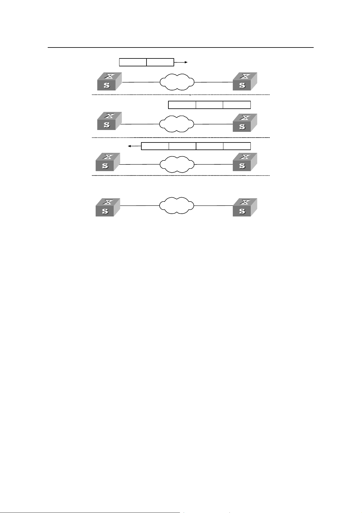
1.1.2 Implementation Principle of NTP
Figure 1-1 shows the implementation principle of NTP.
Ethernet switch A (LS_A) is connected to Ethernet switch B (LS_B) through Ethernet
ports. Both have their own system clocks, and they need to synchronize the clocks of
each other through NTP. To help you to understand the implementation principle, we
suppose that:
NTP Configuration
z Before the system clocks of LS_A and LS_B are synchronized, the clock of LS_A
is set to 10:00:00 am, and the clock of LS_B is set to 11:00:00 am.
z LS_B serves as the NTP server, that is, the clock of LS_A will be synchronized to
that of LS_B.
z It takes one second to transfer an NTP packet from LS_A to LS_B or from LS_A to
LS_B.
1-2
Page 4
Operation Manual – NTP
H3C S3600 Series Ethernet Switches-Release 1510 Chapter 1
NTP Configuration
NTP packet
NTP Packet
NTP Packet
NTP Packet
NTP Packet
NTP Packet
NTP Packet
NTP Packet
1.
1.
1.
1.
1.
1.
1.
1.
2.
2.
2.
2.
2.
2.
2.
2.
3.
3.
3.
3.
3.
3.
3.
3.
4.
4.
4.
4.
4.
4.
4.
4.
LS_A
LS_A
LS_A
LS_A
LS_A
LS_A
LS_A
LS_A
LS_A
LS_A
LS_A
LS_A
LS_A
LS_A
LS_A
LS_A
LS_A
LS_A
LS_A
LS_A
LS_A
LS_A
LS_A
LS_A
NTP Packet received at 10:00:03
NTP Packet received at 10:00:03 am
NTP Packet received at 10:00:03
NTP Packet received at 10:00:03 am
NTP Packet received at 10:00:03
NTP Packet received at 10:00:03 am
NTP Packet received at 10:00:03
NTP packet received at 10:00:03 am
LS_A
LS_A
LS_A
LS_A
LS_A
LS_A
LS_A
LS_A
10:00:00 am
10:00:00 am
10:00:00 am
10:00:00 am
10:00:00am
10:00:00am
10:00:00am
NTP packet
NTP Packet
NTP Packet
NTP Packet
NTP Packet
NTP Packet
NTP Packet
NTP Packet
Network
Network
Network
Network
Network
Network
Network
Network
NTP packet 10:00:00 am
NTP Packet10:00:00am
NTP Packet10:00:00 am
NTP Packet10:00:00am
NTP Packet 10:00:00 am
NTP Packet10:00:00am
NTP Packet10:00:00 am
NTP Packet10:00:00am
Network
Network
Network
Network
Network
Network
Network
Network
10:00:00 am11:00:01 am11:00:02 am
10:00:00am 11:00:01am 11:00:02am
10:00:00 am11:00:01 am 11:00:02 am
10:00:00am 11:00:01am 11:00:02am
10:00:00 am11:00:01 am11:00:02 am
10:00:00am 11:00:01am 11:00:02am
10:00:00 am11:00:01 am 11:00:02 am
10:00:00am 11:00:01am 11:00:02am
Network
Network
Network
Network
Network
Network
Network
Network
Network
Network
Network
Network
Network
Network
Network
Network
Figure 1-1 Implementation principle of NTP
_B
_B
_B
_B
_B
_B
LS
LS
LS
LS
LS
LS
LS_B
LS_B
11:00:01 am
11:00:01am
11:00:01 am
11:00:01am
11:00:01 am
11:00:01am
11:00:01 am
11:00:01am
LS
LS
_B
_B
_B
_B
_B
_B
_B
_B
LS
LS
LS
LS
LS
LS
LSLS_B
LSLS_B
LSLS_B
LS
_B
LSLS_B
LSLS_B
LSLS_B
LS
_B
_B
_B
_B
LS_B
_B
_B
_B
LS_B
The procedure of synchronizing the system clock is as follows:
z LS_A sends an NTP packet to LS_B, with a timestamp 10:00:00 am (T
1
identifying when it is sent.
z When the packet arrives at LS_B, LS_B inserts its own timestamp 11:00:01 am (T
into the packet.
z When the NTP packet leaves LS_B, LS_B inserts its own timestamp 11:00:02 am
) into the packet.
(T
3
z When receiving a response packet, LS_A inserts a new timestamp 10:00:03 am
) into it.
(T
4
At this time, LS_A has enough information to calculate the following two parameters:
z Delay for an NTP packet to make a round trip between LS_A and LS_B:
Delay = (T
z Time offset of LS_A relative to LS_B:
Offset = ((T
-T1)-(T3 -T2).
4
) + (T3 -T4))/2.
2 -T1
LS_A can then set its own clock according to the above information to synchronize its
clock to that of LS_B.
For detailed information, refer to RFC1305.
)
)
2
1-3
Page 5
Operation Manual – NTP
r
H3C S3600 Series Ethernet Switches-Release 1510 Chapter 1
1.1.3 NTP Implementation Modes
According to the network structure and the position of the local Ethernet switch in the
network, the local Ethernet switch can work in multiple NTP modes to synchronize the
clock.
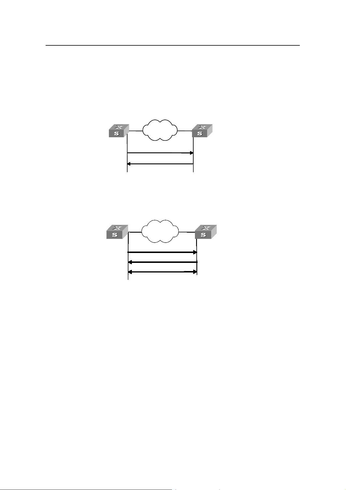
I. Client/server mode
NTP Configuration
Client Se
Filters and selects
a clocks and
synchronize the
local clock to that of
the preferred server
Clock synchronization
request packet
Response packet
Figure 1-2 Client/sever mode
II. Peer mode
Active peer
In peer mode, both
sides can be
synchronized to each
other
Clock synchronization
Network
NetworkNetworkNetwork
NetworkNetworkNetworkNetworkNetworkNetworkNetworkNetworkNetworkNetworkNetworkNetworkNetworkNetworkNetworkNetworkNetworkNetworkNetworkNetworkNetworkNetworkNetworkNetworkNetworkNetworkNetworkNetworkNetworkNetworkNetworkNetworkNetworkNetworkNetworkNetworkNetworkNetworkNetworkNetworkNetworkNetworkNetworkNetworkNetworkNetworkNetworkNetworkNetworkNetworkNetworkNetworkNetworkNetworkNetworkNetworkNetworkNetworkNetworkNetworkNetworkNetworkNetworkNetworkNetworkNetworkNetworkNetworkNetwork
NetworkNetworkNetworkNetworkNetworkNetworkNetworkNetworkNetwork
NetworkNetwork
request packet
Response pac ket
Synchronize
rver
Works in server mode
automatically and send
a response packet
Pas
sive peer
Works in passive pee
mode automatically
Figure 1-3 Peer mod
e
In the peer mode, the local S3600 Ethernet switch serves as the active peer and sends
clock synchronization request packets first, while the remote server serves as the
passive peer automatically.
If both of the peers have reference clocks, the one with a smaller stratum number is
adopted.
1-4
Page 6
Operation Manual – NTP
H3C S3600 Series Ethernet Switches-Release 1510 Chapter 1
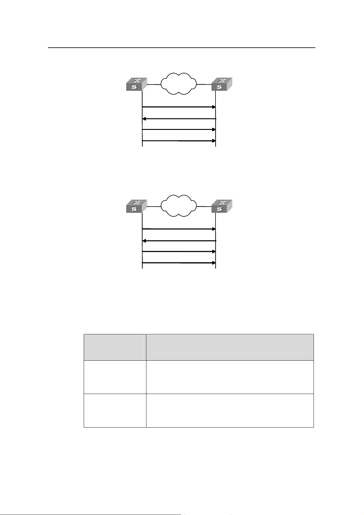
III. Broadcast mode
NTP Configuration
Server
Works in the server
mode automatically and
sends response pack ets
Figure 1-4 Broadcast mod
IV. Multicast mode
Server
Works in the server
mode automatically and
sends response pack ets
Network
Network
NetworkNetwork
Broadcasts clock synchronization
packets periodically
Client/server mode request
Response packet
Broadcasts clock synchronization
packets periodically
e
Network
Network
NetworkNetwork
Multicasts clock synchronization
packets periodically
Client/server mode request
Response packet
Multicasts clock synchronization
packets periodically
Client
Initiates a cl
request after
broadc
Obtains t
client and s
Receives br
Client
Initiates a c
request afte
Obtains t
client and s
Receiv es
he delay between the
the broadc
synchroni
multi
he delay between the
the mult
multicast packets and
synchroni
ient/server mode
receiving the first
ast packet
erver and works in
ast client mode
oadcast packets and
zes the local cl ock
lient/server mode
r receiving the first
cast packet
erver and works in
icast client mode
zes the local clock
Figure 1-5 Multicast mod
e
Table 1-1 describes ho w the above ment ioned NTP modes are impl emented on S3600
series Ethernet switches.
Table 1-1 NTP implementation modes on S3600 series Ethernet switches
NTP
implementation
Configuration on S3600 series switches
mode
Configure the local S3600 Ethernet switch to operate in the
Client/server mode
NTP server mode. In this mode, the remote server serves as
the local time server, while the local switch serves as the
client.
Configure the local S3600 switch to operate in NTP peer
Peer mode
mode. In this mode, the remote server serves as the peer of
the S3600 switch, and the local switch serves as the active
peer.
1-5
Page 7

Operation Manual – NTP
H3C S3600 Series Ethernet Switches-Release 1510 Chapter 1
NTP
implementation
Configuration on S3600 series switches
mode
z Configure the local S3600 Ethernet switch to operate in
NTP broadcast server mode. In this mode, the local
switch broadcasts NTP packets through the VLAN
Broadcast mode
interface configured on the switch.
z Configure the S3600 switch to operate in NTP broadcast
client mode. In this mode, the local S3600 switch
receives broadcast NTP packets through the VLAN
interface configured on the switch.
z Configure the local S3600 Ethernet switch to operate in
NTP multicast server mode. In this mode, the local switch
sends multicast NTP packets through the VLAN interface
Multicast mode
configured on the switch.
z Configure the local S3600 Ethernet switch to operate in
NTP multicast client mode. In this mode, the local switch
receives multicast NTP packets through the VLAN
interface configured on the switch.
NTP Configuration
Caution:
An S3600 Ethernet switch can operate in the NTP peer, NTP broadcast server, or NTP
multicast server mode only after its clock is synchronized.
1.2 Configuring NTP Implementation Modes
An S3600 Ethernet switch can operate in one of the following NTP modes:
z NTP client mode
z NTP server mode
z NTP peer mode
z NTP broadcast server mode
z NTP broadcast client mode
z NTP multicast server mode
z NTP multicast client mode
1.2.1 Configuration Prerequisites
You need to perform configurations only on the client (or the active peer) when you
want an S3600 Ethernet switch to operate in NTP server mode (or NTP peer mode).
However, you need to perform configurations on both the server and client when you
want the switch to operate in NTP broadcast mode or NTP multicast mode.
1-6
Page 8

Operation Manual – NTP
H3C S3600 Series Ethernet Switches-Release 1510 Chapter 1
1.2.2 Configuration Procedure
Table 1-2 Configure NTP implementation modes
Operation Command Description
NTP Configuration
Enter system view
Configure the switch to
operate in NTP client
mode
Configure the switch to
operate in NTP peer
mode
Enter VLAN interface
view
Configure the switch to
operate in the NTP
broadcast client mode
system-view
—
ntp-service
unicast-server
{ remote-ip |
server-name }
[ authentication-keyid
key-id | priority |
source-interface
Optional
By default, no Ethernet
switch operates in NTP
client mode.
Vlan-interface vlan-id |
version number ]*
ntp-service
unicast-peer { remote-ip |
peer-name }
[ authentication-keyid
key-id | priority |
source-interface
Optional
By default, no Ethernet
switch operates in NTP
peer mode.
Vlan-interface vlan-id |
version number ]*
interface Vlan-interface
vlan-id
—
Optional
ntp-service
broadcast-client
By default, no Ethernet
switch operates in NTP
broadcast client mode.
Configure the switch to
operate in NTP broadcast
server mode
Configure the switch to
operate in NTP multicast
client mode
Configure the switch to
operate in NTP multicast
server mode
ntp-service
broadcast-server
[ authentication-keyid
key-id | version number ]*
ntp-service
multicast-client
[ ip-address ]
Optional
By default, no Ethernet
switch operates in NTP
broadcast server mode.
Optional
By default, no Ethernet
switch operates in NTP
multicast client mode.
ntp-service
multicast-server
[ ip-address ]
[ authentication-keyid
keyid | ttl ttl-number |
Optional
By default, no Ethernet
switch operates in NTP
multicast server mode.
version number ]*
1-7
Page 9

Operation Manual – NTP
H3C S3600 Series Ethernet Switches-Release 1510 Chapter 1
Note:
To reduce the risk of being attacked by malicious users against opened socket and
enhance switch security, the S3600 series Ethernet switches provide the following
functions, so that a socket is opened only when it is needed:
z Opening UDP port 123 (used for NTP) when NTP is enabled;
z Close UDP port 123 when NTP is disabled.
The preceding functions are implemented as follows:
z When you enable NTP by using the ntp-service unicast-server, ntp-service
unicast-peer, ntp-service broadcast-client, ntp-service broadcast-server,
ntp-service multicast-client, or ntp-service multicast-server command, UDP
port 123 is opened at the same time.
z When you disable NTP from operating in any modes by using the undo forms of the
preceding six commands, UDP port 123 is closed at the same time.
I. NTP client mode
NTP Configuration
z The remote server specified by the remote-ip or server-name argument serves as
the NTP server. The local S3600 Ethernet switch serves as th e client. The clock of
the client is synchronized to the NTP server, while the clock of the NTP server is
not synchronized to the client.
z The IP address specified by the remote-ip argument cannot be a broadcast
address, a multicast address, or the IP address used by the local reference clock.
II. NTP peer mode
z The remote server specified by the remote-ip or peer-name argument serves as
the peer of the local Ethernet switch, and the local Ethernet switch operates in the
active peer mode. The clock of the local switch can be synchronized to the remote
server or used to synchronize the clock of the remote serve r.
z The IP address specified by the remote-ip argument cannot be a broadcast
address, a multicast address, or the IP address used by the local reference clock.
III. NTP broadcast server mode
When an S3600 Ethernet switch operates in NTP broadcast server mode, it broadcasts
clock synchronization packets periodically. The devices in NTP broadcast client mode
will respond to these packets and start the clock synchronization process.
1-8
Page 10

Operation Manual – NTP
H3C S3600 Series Ethernet Switches-Release 1510 Chapter 1
IV. NTP multicast server mode
When an S3600 Ethernet switch operates in NTP multicast server mode, it multicasts
clock synchronization packets periodically. The devices in the NTP multicast client
mode will respond to these packets and start the clock synchronization process. The
switch operating in this mode can support up to 1,024 multicast clients.
Note:
z The total number of the servers and peers configured for a switch is up to 128.
z After the configuration, an S3600 Ethernet switch does not establish connections
with peers if it operates in NTP server mode. Whereas if it operates in any of the
other modes, it establishes connections with peers.
z If an S3600 Ethernet switch operates in passive peer mode, NTP broadcast client
mode, or NTP multicast client mode, it establishes connections with peers
dynamically. If it operates in any of the other modes, it establishes connections with
peers statically.
NTP Configuration
1.3 Configuring Access Control Right
The access control right to the NTP server only provides a minimal degree of security
measure. A more secure way is to perform identity authentication.
The right of an access request received by the NTP server is matched from the highest
to the lowest in order of peer, server, synchronization, and query.
Table 1-3 Configure the access control right to the local NTP server
Operation Command Description
Enter system view
Configure the access
control right to the local
NTP server
system-view
ntp-service access
{ peer | server |
synchronization |
query } acl-number
1.4 Configuring NTP Authentication
—
Optional
By default, the access
control right to the local
NTP server is peer.
In networks with higher security requirements, the NTP authentication function mu st be
enabled to run NTP. Through password authentication on the client and the se rver, the
client is synchronized only to the server that passes the authentication. This improves
network security.
1-9
Page 11

Operation Manual – NTP
H3C S3600 Series Ethernet Switches-Release 1510 Chapter 1
1.4.1 Configuration Prerequisites
NTP authentication configuration involves:
z Configuring NTP authentication on the client
z Configuring NTP authentication on the server
Observe the following principles when configuring NTP authentication:
z If the NTP authentication function is not enabled on the client, the client can be
synchronized to a server no matter whether the NTP authentication function is
enabled on the server (assuming that other related configurations are perfo rmed).
z You need to couple the NTP authentication with a trusted key.
z Configurations on the server and the client must be consistent.
z The client with the NTP authentication function enabled is only synchronized to the
server that provides a trusted key.
1.4.2 Configuration Procedure
I. Configuring NTP authentication on the client
NTP Configuration
Table 1-4 Configure NTP authentication on the client
Operation Command Description
Enter system view
Enable the NTP
authentication
function globally
Configure the
NTP
authentication key
Configure the
specified key to
be a trusted key
system-view
ntp-service authentication
enable
ntp-service
authentication-keyid key-id
authentication-model md5
value
ntp-service reliable
authentication-keyid key-id
NTP client mode:
ntp-service unicast-server
{ remote-ip | server-name }
Associate the
aut
specified key with
the corresponding
NTP server
Peer mode:
ntp-service unicast-peer
{ remote-ip | peer-name }
authentication-keyid key-id
hentication-keyid key-id
—
Required
By default, the NTP
authentication function is
disabled.
Required
By default, no NTP
authentication key is
configured.
Required
By default, no trusted key is
configured.
z In NTP client mode and
NTP peer mode, you need
to associate the specified
key with the corresponding
NTP server on the client.
z You can associate the NTP
server with the
authentication key while
configuring NTP mode. You
can also use this command
to associate them after
configuring NTP mode.
1-10
Page 12

Operation Manual – NTP
H3C S3600 Series Ethernet Switches-Release 1510 Chapter 1
Note:
z NTP authentication requires that the authentication keys configured for the server
and the client are the same. Besides, the authentication keys must be truste d keys.
Otherwise, the client cannot be synchronized with the server.
z In NTP server mode and NTP peer mode, you need to associate the specified key
with the corresponding NTP server (active peer) on the client (passive peer). In
these two modes, multiple servers (active peers) may be configured for a
client/passive peer, and therefore, the authentication key is required to determine
which server the client is synchronized to.
II. Configuring NTP authentication on the server
Table 1-5 Configure NTP authentication on the server
Operation Command Description
NTP Configuration
Enter system view
Enable NTP
authentication
system-view
ntp-service authentication
enable
ntp-service
Configure an NTP
authentication key
authentication-keyid key-id
authentication-mode md5
value
Configure the
specified key to be
a trusted key
Enter VLAN
interface view
ntp-service reliable
authentication-keyid key-id
interface Vlan-interface
vlan-id
Broadcast server mode:
ntp-service
broadcast-server
authentication-keyid key-id
Associate the
specified key with
the corresponding
NTP server
Multicast server mode:
ntp-service
multicast-server
authentication-keyid key-id
—
Required
By default, the NTP
authentication function is
disabled.
Required
By default, no NTP
authentication key is
configured.
Required
By default, no trusted
authentication key is
configured.
—
z In NTP broadcast server
mode and NTP multicast
server mode, you need to
associate the specified key
with the corresponding
NTP server on the server
z You can associate an NTP
server with an
authentication key while
configuring NTP mode.
You can also use this
command to associate
them after configuring the
NTP mode.
1-11
Page 13

Operation Manual – NTP
H3C S3600 Series Ethernet Switches-Release 1510 Chapter 1
Note:
The procedure for configuring NTP authentication on the server is the same a s that on
the client. Besides, the client and the server must be configured with the same
authentication key.
1.5 Configuring Optional NTP Parameters
Optional NTP parameters are:
z Local VLAN interface that sends NTP packets
z Number of dynamic sessions that can be established locally
z VLAN interface disabled from receiving NTP packets
Table 1-6 Configure optional NTP parameters
Operation Command Description
NTP Configuration
Enter system view
Configure a local
interface that sends
NTP packets
Configure the
number of sessions
that can be
established locally
Enter VLAN
interface view
Disable an interface
from receiving NTP
packets
system-view
ntp-service
source-interface
Vlan-interface vlan-id
ntp-service
max-dynamic-sessions
number
interface Vlan-interface
vlan-id
ntp-service in-interface
disable
—
Optional
Optional
By default, up to 100 dynamic
sessions can be established
locally.
—
Optional
By default, a VLAN interface
receives NTP packets.
Caution:
z If a sending interface is specified in the ntp-service unicast-server command or
the ntp-serv ice unicast-peer command, the source IP address of an NTP packet is
the address of this interface.
z Dynamic connections can be established when a switch operates in passive peer
mode, NTP broadcast client mode, or NTP multicast client mode. In other modes,
the connections established are static.
1-12
Page 14

Operation Manual – NTP
H3C S3600 Series Ethernet Switches-Release 1510 Chapter 1
1.6 Displaying and Debugging NTP
After the above configurations, you can execute display commands in any view to
display the running status of switch, and verify the effect of the configurations.
Table 1-7 Display and debug NTP
Operation Command Description
NTP Configuration
Display the status of NTP services
Display the information about the
sessions maintained by NTP
Display the brief information about
NTP servers along the path from
the local device to the reference
clock source
1.7 Configuration Example
1.7.1 Configuring NTP Server Mode
I. Network requirements
The local clock of H3C1 is set to the NTP master clock, with a stratum level of 2.
Note:
H3C1 is a switch that allows the local clock to serve as the NTP master clock.
display ntp-service status
display ntp-service
sessions [ verbose ]
display ntp-service trace
The display
commands
can be
executed in
any view
An S3600 Ethernet switch considers H3C1 as the NTP server and operates in client
mode, while H3C1 operates in server mode automatically.
II. Network diagram
12/24
12/24
1.0.1.
1.0.1.
1.0.1.11/24
1.0.1.11/24
S3600
H3C1
H3C1
Figure 1-6 Network diagram for the NTP server mode configuration
S3600
III. Configuration procedure
Perform the following configurations on the S3600 switch.
# View the NTP status of the S3600 switch before synchronization.
1-13
Page 15

Operation Manual – NTP
H3C S3600 Series Ethernet Switches-Release 1510 Chapter 1
<S3600> display ntp-service status
Clock status: unsynchronized
Clock stratum: 16
Reference clock ID: none
Nominal frequency: 60.0002 Hz
Actual frequency: 60.0002 Hz
Clock precision: 2^18
Clock offset: 0.0000 ms
Root delay: 0.00 ms
Root dispersion: 0.00 ms
Peer dispersion: 0.00 ms
Reference time: 00:00:00.000 UTC Jan 1 1900 (00000000.00000000)
# Set H3C1 to the NTP server of the S3600 switch.
<S3600> system-view
[S3600] ntp-service unicast-server 1.0.1.11
# (After the above configurations, the S3600 switch is synchronized to H3C1.) V iew the
NTP status of the S3600 switch.
NTP Configuration
[S3600] display ntp-service status
Clock status: synchronized
Clock stratum: 3
Reference clock ID: 1.0.1.11
Nominal frequency: 60.0002 Hz
Actual frequency: 60.0002 Hz
Clock precision: 2^18
Clock offset: 0.0000 ms
Root delay: 9.54 ms
Root dispersion: 26.42 ms
Peer dispersion: 10.96 ms
Reference time: 07:05:43.263 UTC Apr 25 2006(C7F848C7.438348F5)
The above output information indicates that the S3600 switch is synchronized to H3C1,
and the stratum level of its clock is 3, one level lower than that of H3C1.
# View the information about NTP sessions of the S3600 switch. (You can see that the
S3600 switch establishes a connection with H3C1.)
[S3600] display ntp-service sessions
source reference stra reach poll now offset delay disper
**************************************************************************
[12345]1.0.1.11 127.127.1.0 2 255 64 39 0.0 9.5 5.1
note: 1 source(master),2 source(peer),3 selected,4 candidate,5 configured
1-14
Page 16

Operation Manual – NTP
H3C S3600 Series Ethernet Switches-Release 1510 Chapter 1
1.7.2 Configuring NTP Peer Mode
I. Network requirements
The local clock of H3C2 is set to the NTP maste r clock, with the clock strat um level of 2.
An S3600 Ethernet switch considers H3C2 as the NTP server a nd serves as the client,
while H3C2 operates in server mode automatically. In addition, H3C3 considers the
S3600 Ethernet switch as its peer.
Note:
This example assumes that:
z H3C2 is a switch that allows its local clock to be the mast er clock.
z H3C3 is a switch that allows its local clock to be the master clock and the stratum
level of its clock is 1.
NTP Configuration
II. Network diagram
H3 C 2
H3 C 2
3.0.1.
3.0.1.
31/24
31/24
3.0.1.32/24
H3 C 3
H3 C 3
3.0.1.32/24
S3600
S3600
3.0.1.33/24
3.0.1.33/24
Figure 1-7 Network diagram for NTP peer mode configuration
III. Configuration procedure
1) Configure the S3600 series switch.
# Set H3C2 to the NTP server.
<S3600> system-view
[S3600] ntp-service unicast-server 3.0.1.31
2) Configure H3C3 (after the S3600 Ethernet switch is synchronized to H3C2).
# Enter system view.
<H3C3> system-view
[H3C3]
# Set the S3600 Ethernet switch to the peer of H3C3.
1-15
Page 17

Operation Manual – NTP
H3C S3600 Series Ethernet Switches-Release 1510 Chapter 1
[H3C3] ntp-service unicast-peer 3.0.1.33
The S3600 Ethernet switch and H3C3 are a pair of peers. H3C3 operates in active peer
mode, while the S3600 Ethernet switch operates in passive peer mode. Because the
stratum level of the local clock of H3C3 is 1, and that of the S3600 Ethernet swit ch is 3,
the S3600 Ethernet switch is synchronized to H3C3.
View the status of the S3600 Ethernet switch after synchronization.
[S3600] display ntp-service status
Clock status: synchronized
Clock stratum: 2
Reference clock ID: 3.0.1.32
Nominal frequency: 60.0002 Hz
Actual frequency: 60.0002 Hz
Clock precision: 2^18
Clock offset: 0.0000 ms
Root delay: 31.28 ms
Root dispersion: 0.08 ms
Peer dispersion: 27.31 ms
Reference time: 07:07:59.823 UTC Apr 25 2006(C7F8494F.D2E568A5)
NTP Configuration
The output information indicates that the S3600 Ethernet switch is synchronized to
H3C3 and the stratum level of its local clock is 2, one level lower than that H3C3.
# View the information about the NTP sessions of the S3600 Ethernet switch (you can
see that a connection is established between the S3600 Ethernet switch and H3C3).
[S3600] display ntp-service sessions
source reference stra reach poll now offset delay disper
**************************************************************************
[2]3.0.1.32 LOCL 1 14 64 60 -1.0 0.0 1.6
note: 1 source(master),2 source(peer),3 selected,4 candidate,5 configured
1.7.3 Configuring NTP Broadcast Mode
I. Network requirements
The local clock of H3C3 is set to the NTP master clock, with a stratum level of 2. NTP
packets are broadcast through Vlan-interface2.
Configure S3600-1 and S3600-2 to listen to broadcast packets through their own
Vlan-interface2.
1-16
Page 18

Operation Manual – NTP
H3C S3600 Series Ethernet Switches-Release 1510 Chapter 1
Note:
This example assumes that H3C3 is a switch that supports the local clock being the
master clock.
II. Network diagram
3.0.1.31/24
3.0.1.31/24
rface 2
rface 2
Vlan-inte
1.0.1.31/24
1.0.1.31/24
Vlan
Vlan
-interface 2
S3600-2 H3C 4
S3600-2 H3C 4
-interface 2
Vlan-inte
Vlan-inte
Vlan-inte
3.0.1.32/24
3.0.1.32/24
rface 2
rface 2
H3C 3
H3C 3
S3600-1
S3600-1
NTP Configuration
Figure 1-8 Network diagram for the NTP broadcast mode configuration
III. Configuration procedure
1) Configure H3C3.
# Enter system view.
<H3C3> system-view
[H3C3]
# Enter Vlan-interface2 view.
[H3C3] interface Vlan-interface 2
[H3C3-Vlan-interface2]
# Set H3C3 to the broadcast server, which sends broadcast packets through
Vlan-interface2.
[H3C3-Vlan-interface2] ntp-service broadcast-server
2) Configure S3600-1.
# Enter system view.
<S3600-1> system-view
[S3600-1]
# Enter Vlan-interface2 view.
[S3600-1] interface Vlan-interface 2
[S3600-1-Vlan-interface2]
# Set S3600-1 to a broadcast client.
[S3600-1-Vlan-interface2] ntp-service broadcast-client
1-17
Page 19

Operation Manual – NTP
H3C S3600 Series Ethernet Switches-Release 1510 Chapter 1
3) Configure S3600-2
# Enter system view.
<S3600-2> system-view
[S3600-2]
# Enter Vlan-interface2 view.
[S3600-2] interface Vlan-interface 2
[S3600-2-Vlan-interface2]
# Set S3600-2 to a broadcast client.
[S3600-2-Vlan-interface2] ntp-service broadcast-client
After the above configurations, S3600-1 and S3600-2 will listen to broadcast packets
through their own Vlan-interface2, and H3C3 will send broadcast packets through
Vlan-interface2. Because S3600-2 and H3C3 do not share th e same network segment,
S3600-2 cannot receive broadcast packets from H3C3, while S3600-1 is syn chronized
to H3C3 after receiving broadcast packets from H3C3.
View the status of S3600-1 after synch r onization.
NTP Configuration
[S3600-1] display ntp-service status
Clock status: synchronized
Clock stratum: 3
Reference clock ID: 3.0.1.31
Nominal frequency: 60.0002 Hz
Actual frequency: 60.0002 Hz
Clock precision: 2^18
Clock offset: -9.1060 ms
Root delay: 15.84 ms
Root dispersion: 3.52 ms
Peer dispersion: 29.62 ms
Reference time: 07:15:14.403 UTC Apr 25 2006(C7F84B02.6735F3D7)
The output information indicates that S3600-1 is synchronized to H3C3, with the clock
stratum level of 3, one level lower than that of H3C3.
# View the information about the NTP sessions of S3600-1 and you can see that a
connection is established between S3600-1 and H3C3.
[S3600-1] display ntp-service sessions
source reference stra reach poll now offset delay disper
**************************************************************************
[1]3.0.1.31 127.127.1.0 2 14 64 60 -1.0 0.0 1.6
note: 1 source(master),2 source(peer),3 selected,4 candidate,5 configured
1-18
Page 20

Operation Manual – NTP
H3C S3600 Series Ethernet Switches-Release 1510 Chapter 1
1.7.4 Configuring NTP Multicast Mode
I. Network requirements
The local clock of H3C3 is set to the NTP master clock, with a clock stratum level of 2.
H3C3 advertises multicast packets th rough Vlan-interface2.
S3600-1 and S3600-2 respectively listen to multicast packets through their own
Vlan-interface2.
Note:
This example assumes that H3C3 is a switch that supports the local clock being the
master clock.
II. Network diagram
NTP Configuration
3.0.1.31/24
3.0.1.31/24
Vlan-inte
Vlan-inte
rface 2
1.0.1.31/24
1.0.1.31/24
-interface 2
-interface 2
Vlan
Vlan
S3600-2 H3C 4
S3600-2 H3C 4
Vlan-inte
Vlan-inte
rface 2
3.0.1.32/24
3.0.1.32/24
rface 2
rface 2
H3C 3
H3C 3
S3600-1
S3600-1
Figure 1-9 Network diagram for NTP multicast mode configuration
III. Configuration procedure
1) Configure H3C3.
# Enter system view.
<H3C3> system-view
[H3C3]
# Enter VLAN-interface2 view.
[H3C3] interface Vlan-interface 2
# Set H3C3 to a multicast server.
[H3C3-Vlan-interface2] ntp-service multicast-server
2) Configure S3600-1.
# Enter system view.
<S3600-1> system-view
1-19
Page 21

Operation Manual – NTP
H3C S3600 Series Ethernet Switches-Release 1510 Chapter 1
[S3600-1]
# Enter Vlan-interface2 view.
[S3600-1] interface Vlan-interface 2
# Set S3600-1 to a multicast client.
[S3600-1-Vlan-interface2] ntp-service multicast-client
3) Configure S3600-2.
# Enter system view.
<S3600-2> system-view
[S3600-2]
# Enter Vlan-interface2 view.
[S3600-2] interface Vlan-interface 2
# Set S3600-2 to a multicast client.
[S3600-2-Vlan-interface2] ntp-service multicast-client
After the above configurations, S3600-1 and S3600-2 respectively listen to multicast
packets through their own Vlan-interface2, and H3C3 advertises multicast packets
through Vlan-interface2. Because S3600-2 and S3600-3 do not share the same
network segment, S3600-2 cannot receive multicast packets from H3C3, while
S3600-1 is synchronized to H3C3 after receiving multicast packets from H3C3.
NTP Configuration
View the status of S3600-1 after synch r onization.
[S3600-1] display ntp-service status
Clock status: synchronized
Clock stratum: 3
Reference clock ID: 3.0.1.31
Nominal frequency: 60.0002 Hz
Actual frequency: 60.0002 Hz
Clock precision: 2^18
Clock offset: 0.0000 ms
Root delay: 63.21 ms
Root dispersion: 0.30 ms
Peer dispersion: 46.13 ms
Reference time: 07:18:32.952 UTC Apr 25 2006(C7F84BC8.F3BBD7B2)
The output information indicates that S3600-1 is synchronized to H3C3, with a clock
stratum level of 3, one stratum level lower than that H3C3.
# View the information about the NTP sessions of S3600-1 (You can see that a
connection is established between S3600-1 and H3C3).
[S3600-1] display ntp-service sessions
source reference stra reach poll now offset delay disper
**************************************************************************
1-20
Page 22

Operation Manual – NTP
H3C S3600 Series Ethernet Switches-Release 1510 Chapter 1
[1]3.0.1.31 127.127.1.0 2 1 64 20 0.0 15.4 0.0
note: 1 source(master),2 source(peer),3 selected,4 candidate,5 configured
1.7.5 Configuring NTP Server Mode with Authentication
I. Network requirements
The local clock of H3C1 is set to the NTP master clock, with a clock stratum level of 2.
An S3600 Ethernet switch considers H3C1 as the NTP server and operates in client
mode, while H3C1 operates in server mode automatically. In addition, the NTP
authentication function is enabled on both sides.
Note:
This example assumes that H3C1 is a switch that supports the local clock being the
NTP master clock.
NTP Configuration
II. Network diagram
1.0.1.
1.0.1.
12/24
12/24
1.0.1.11/24
1.0.1.11/24
S3600
H3C1
H3C1
S3600
Figure 1-10 Network diagram for NTP se rver mode with authentication configuration
III. Configuration procedure
1) Configure the S3600 Ethernet switch.
# Enter system view.
<S3600> system-view
[S3600]
# Set H3C1 to the NTP server.
[S3600] ntp-service unicast-server 1.0.1.11
# Enable the NTP authentication function.
[S3600] ntp-service authentication enable
# Configure an MD5 authentication key, with the key ID being 42 and the key being
aNiceKey.
[S3600] ntp-service authentication-keyid 42 authentication-mode md5 aNiceKey
# Specify the key as a trusted key.
[S3600] ntp-service reliable authentication-keyid 42
1-21
Page 23

Operation Manual – NTP
H3C S3600 Series Ethernet Switches-Release 1510 Chapter 1
[S3600] ntp-service unicast-server 1.0.1.11 authentication-keyid 42
After the above configurations, S3600 is ready to synchronize with H3C1. Because the
NTP authentication function is not enabled on H3C1, S3600 will fail to be synchronized
to H3C1.
To synchronize the S3600 Ethernet switch, you need to perform the following
configurations on H3C1.
# Enable the NTP authentication function on H3C1.
[H3C1] system-view
[H3C1] ntp-service authentication enable
# Configure an MD5 authentication key, with the key ID being 42 and the key being
aNiceKey.
[H3C1] ntp-service authentication-keyid 42 authentication-mode md5 aNiceKey
# Specify the key as a trusted key.
[H3C1] ntp-service reliable authentication-keyid 42
(After the above configurations, the S3600 Ethernet switch can be synchronized to
H3C1.) View the status of S3600 after synchronization.
NTP Configuration
[S3600] display ntp-service status
Clock status: synchronized
Clock stratum: 3
Reference clock ID: 1.0.1.11
Nominal frequency: 60.0002 Hz
Actual frequency: 60.0002 Hz
Clock precision: 2^18
Clock offset: 0.0000 ms
Root delay: 9.54 ms
Root dispersion: 26.42 ms
Peer dispersion: 10.96 ms
Reference time: 07:05:43.263 UTC Apr 25 2006(C7F848C7.438348F5)
The output information indicates that S3600 is synchronized to H3C1, with a clock
stratum level of 3, one stratum level lower than that H3C1.
# View the information about NTP sessions of S3600 (You can see that a connection is
established between S3600 and H3C1).
<S3600> display ntp-service sessions
source reference stra reach poll now offset delay disper
**************************************************************************
[5]1.0.1.11 127.127.1.0 2 255 64 39 0.0 9.5 5.1
note: 1 source(master),2 source(peer),3 selected,4 candidate,5 configured
1-22
 Loading...