

Page 1

H3C S3100 Series Ethernet Switches
Operation Manual
Hangzhou H3C Technologies Co., Ltd.
http://www.h3c.com
Manual Version: 20080710-C-1.05
Page 2

Copyright © 2007-2008, Hangzhou H3C Te chnologie s Co., Ltd . and it s licen sors
All Rights Reserved
No part of this manual may be reproduced or transmitted in any form or by any means
without prior written consent of Hangzhou H3C Technologies Co., Ltd.
Trademarks
H3C, , Aolynk, , H3Care,
Neocean, NeoVTL, SecPro, SecPoint, SecEngine, SecPath, Comware, Secware,
Storware, NQA, VVG, V
HUASAN are trademarks of Hangzhou H3C Technologies Co., Ltd.
All other trademarks that may be mentioned in this manual are the property of their
respective owners.
Notice
The information in this document is subject to change without notice. Every effort has
been made in the preparation of this document to ensure accuracy of the content s, but
all statements, information, and recommendations in this document do not constitute
the warranty of any kind, express or implied.
Technical Support
customer_service@h3c.com
http://www.h3c.com
, TOP G, , IRF, NetPilot,
2
G, VnG, PSPT, XGbus, N-Bus, TiGem, InnoVision and
Page 3

About This Manual
Organization
H3C S3100 Series Ethernet Switches Operation Manual is organized as follows:
Part Contents
0 Product Overview
1 CLI
2 Login
3 Configuration File
Management
4 VLAN
5 Management VLAN Introduces the management VLAN configuration.
6 IP Address-IP Performance
7 Voice VLAN
8 GVRP Introduces GVRP and the related configuration.
9 Port Basic Configuration Introduces basic port configuration.
10 Link Aggregation
Introduces the characteristics and
implementations of the Ethernet switch.
Introduces the command hierarchy, command
view and CLI features of the Ethernet switch.
Introduces the ways to log into an Ethernet
switch.
Introduces the ways to manage configuration
files.
Introduces VLAN fundamental and the related
configuration.
Introduces IP address and IP performance
fundamental and the related configuration.
Introduces voice VLAN fundamental and the
related configuration.
Introduces link aggregation and the related
configuration.
11 Port Isolation
12 Port Security-Port Binding
13 DLDP Introduces DLDP and the related configuration.
14 MAC Address Table
Management
15 MSTP Introduces STP and the related configuration.
16 Multicast Introduces the configuration of IGMP Snooping.
17 802.1x-System Guard
Introduces port isolation and the related
configuration.
Introduces port security, port binding, and the
related configuration.
Introduces MAC address forwarding table and
the related configuration.
Introduces 802.1x, System-Guard and the
related configuration.
Page 4

Part Contents
18 AAA
19 MAC Address
Authentication
Introduces AAA, RADIUS, HWTACACS, EAD,
and the related configurations.
Introduces MAC address authentication and the
related configuration.
20 ARP Introduces ARP and the related configuration.
21 DHCP
Introduces DHCP, DHCP-Snooping, and the
related configurations.
22 ACL Introduces ACL and the related configuration.
23 QoS-QoS Profile
24 Mirroring
25 Stack-Cluster
26 PoE-PoE Profile
27 SNMP-RMON
Introduces QoS, QoS profile and the related
configuration.
Introduces port mirroring and the related
configuration.
Introduces the configuration to form clusters
using HGMP V2.
Introduces PoE, PoE profile and the related
configuration.
Introduces the configuration to manage network
devices through SNMP and RMON.
28 NTP Introduces NTP and the related configuration.
29 SSH Introduces SSH and the related configuration.
30 File System Management
31 FTP-SFTP-TFTP
32 Information Center
33 System Maintenance and
Debugging
34 VLAN-VPN
Introduces basic configuration for file system
management.
Introduces basic configuration for FTP, SFTP,
TFTP, and the applications.
Introduces the configuration to analyze and
diagnose networks using the information center.
Introduces daily system maintenance and
debugging.
Introduces VLAN VPN and the related
configuration.
35 HWPing Introduces HWPing and the related configuration.
36 IPv6 Management
Introduces IPv6 Management and the related
configuration.
37 DNS Introduces DNS and the related config uration.
38 Smart Link-Monitor Link
Introduces Smart Link, Monitor Link and the
related configuration.
39 Appendix Lists the acronyms used in this manual.
Page 5
Conventions
The manual uses the following conventions:
I. Command conventions
Convention Description
Boldface
italic
[ ]
{ x | y | ... }
[ x | y | ... ]
{ x | y | ... } *
[ x | y | ... ] *
&<1-n>
# A line starting with the # sign is comments.
The keywords of a command line are in Boldface.
Command arguments are in italic.
Items (keywords or arguments) in square brackets [ ] are
optional.
Alternative items are grouped in braces and separated by
vertical bars. One is selected.
Optional alternative items are grouped in square brackets
and separated by vertical bars. One or none is selected.
Alternative items are grouped in braces and separated by
vertical bars. A minimum of one or a maximum of all can be
selected.
Optional alternative items are grouped in square brackets
and separated by vertical bars. Many or none can be
selected.
The argument(s) before the ampersand (&) sign can be
entered 1 to n times.
II. GUI conventions
Convention Description
Boldface
>
III. Symbols
Convention Description
Warning
Caution
Window names, button names, field names, and menu
items are in Boldface. For example, the New User window
appears; click OK.
Multi-level menus are separated by angle brackets. For
example, File > Create > Folder.
Means reader be extremely careful. Improper operation
may cause bodily injury.
Means reader be careful. Improper operation may cause
data loss or damage to equipment.
Page 6
Convention Description
Note Means a complementary description.
Related Documentation
In addition to this manual, each H3C S3100 Series Ethernet Switches documentation
set includes the following:
Manual Description
H3C S3100 Series Ethernet Switches
Installation Manual
H3C S3100 Series Ethernet Switches
Command Manual
H3C S3100 Series Ethernet Switches
Compliance and Safety Manual
Obtaining Documentation
You can access the most up-to-date H3C product documentation on the World Wide
Web at this URL: http://www.h3c.com.
The following are the columns from which you can obtain different categories of product
documentation:
[Products & Solutions]: Provides information about products and technologies.
[Technical Support & Document > Technical Documents]: Provides several categories
of product documentation, such as installation, operation, and maintenance.
It provides information for the system
installation.
It is used for assisting the users in using
various commands.
It lists the regulatory compliance
statements and provides the safety
information of H3C S3100 series
Ethernet switches.
[Technical Support & Document > Product Support > Software]: Provides the
documentation released with the software version.
Documentation Feedback
You can e-mail your comments about product documentation to info@h3c.com.
We appreciate your comments.
Page 7

Operation Manual – Product Overview
H3C S3100 Series Ethernet Switches Table of Contents
Table of Contents
Chapter 1 Obtaining the Documentation ....................................................................................1-1
1.1 CD-ROM............................................................................................................................1-1
1.2 H3C Website......................................................................................................................1-1
1.3 Software Release Notes.................................................................................................... 1-2
Chapter 2 Correspondence Between Documentation and Software.......................................2-1
2.1 Manual List.........................................................................................................................2-1
2.2 Software Version................................................................................................................2-1
Chapter 3 Product Overview........................................................................................................3-1
3.1 Overview............................................................................................................................ 3-1
3.2 Software Features ............................................................................................................. 3-1
Chapter 4 Network Design............................................................................................................ 4-1
4.1 MAN Access Solution........................................................................................................4-1
4.2 Education Network Solution...............................................................................................4-1
4.3 Multi-Service Carrier VLAN Solution..................................................................................4-2
i
Page 8

Operation Manual – Product Overview
H3C S3100 Series Ethernet Switches Chapter 1 Obtaining the Documentation
Chapter 1 Obtaining the Documentation
Hangzhou H3C Technologies Co., Ltd. provides various ways for you to obtain
documentation, through which you can obtain the product documentations and those
concerning newly added new features. The document ations are available in on e of the
following ways:
z CD-ROMs shipped with the devices
z H3C website
z Software release notes
1.1 CD-ROM
H3C delivers a CD-ROM together with each device. The CD-ROM contains the
operation manual and command manual. After installing the reader program provided
by the CD-ROM, you can search for the desired contents in a convenient way through
the reader interface.
The contents in the manual are subject to update on an irregular basis due to product
version upgrade or some other reasons. Therefore, the contents in the CD-ROM may
not be the latest version. This manual serves the purpose of user guide only. Unless
otherwise noted, all the information in the document set does not claim or imply any
warranty. For the latest software documentation, go to the H3C website.
1.2 H3C Website
Perform the following steps to query and download the product do cumentation from the
H3C website.
Table 1-1 Acquire product documentation from the H3C website
Registering
Acquire product
documentation
Access the homepage of H3C at http:// www.h3c.com and click
on Registration at the top right. In the displayed page, provide
your information and click on Submit to register.
Approach 1:
In the homepage of H3C at http:// www.h3c.com, select Technical
Support & Document > Technical Documents from the navigation
menu at the top. Then select a product for its documents.
Approach 2:
In the homepage of H3C at http:// www.h3c.com, select Support >
Technical Documents. Then select a product for its documents.
1-1
Page 9

Operation Manual – Product Overview
H3C S3100 Series Ethernet Switches Chapter 1 Obtaining the Documentation
1.3 Software Release Notes
With software upgrade, new software features may be added. You can acquire the
information about the newly added software features through software release notes.
1-2
Page 10

Operation Manual – Product Overview
H3C S3600 Series Ethernet Switches
Chapter 2 Correspondence Between
Documentation and Software
2.1 Manual List
Chapter 2 Correspondence Between Documentation
and Software
H3C S3100 Series Ethernet Switches Installation Manual
H3C S3100 Series Ethernet Switches Quick Start
H3C S3100 Series Ethernet Switches Compliance and
Safety Manual
H3C S3100 Series Ethernet Switches Operation Manual
H3C S3100 Series Ethernet Switches Command Manual
2.2 Software Version
H3C S3100 Series Ethernet Switches Operation Manual and H3C S3100 Series
Ethernet Switches Command Manual are for the software versions list in
the S3100-SI series and S3100-EI series switches.
Table 2-1 Corresponding software versions of this manual
Switch Software Version
Manual name
Corresponding
Product
S3100-SI series
S3100-EI series
Table 2-1 of
S3100-SI series Release2102, Release2107
S3100-EI series Release2104, Release2107, Release2107P01
The supported features are different between these softwa re versions.
z Compared with Release 2102, some new features are added in Release 2107 of
the S3100-SI series switches. For details, refer to
z Compared with Release 2104, some new features are added in Release 2107 and
Release 2107P01 of the S3100-EI series switches. For details, refer to
2-1
Table 2-2.
Table 2-3.
Page 11
Operation Manual – Product Overview
H3C S3600 Series Ethernet Switches
Table 2-2 Added features compared with the earlier software version of S3100-SI
Chapter 2 Correspondence Between Documentation
and Software
Software
Version
Added Features Compared With The
Earlier Version
Assigning MAC Addresses for Ethernet
Ports
ARP Source MAC Address Consistency
Check
Local authentication after failed of
remote authentication
Manual
14-MAC Address Table
Management
20-ARP
18-AAA
Unauthorized DHCP Server Detection 21-DHCP
Release2107
SNMP AES 128 27-SNMP-RMON
rsa peer-public-key import 29-SSH
FTP disconnect 31-FTP-SFTP-TFTP
Identifying and Diagnosing Pluggable
Transceivers
33-System Maintenance
and Debugging
IPv6 Management 36-IPv6 Management
Table 2-3 Added features compared with the earlier software version of S3100-EI
Software
Version
Release2107
P01
Release2107
Added Features Compared With The
Earlier Version
Manual
Configuring loopback detection for a list of
ports in bulk
09-Port Basic
Configuration
Enabling auto-shutdown of loopback ports
ARP Source MAC Address Consistency
Check
Assigning MAC Addresses for Ethernet
Ports
20-ARP
14-MAC Address
Table Management
Traffic Shaping 23-QoS-QoS Profile
SNMP AES 128 27-SNMP-RMON
rsa peer-public-key import 29-SSH
FTP disconnect 31-FTP-SFTP-TFTP
2-2
Page 12

Operation Manual – Product Overview
H3C S3100 Series Ethernet Switches Chapter 3 Product Overview
Chapter 3 Product Overview
Note:
For the convenience of users, units of Mega bps/1000 Mega bps in the following
chapters are simplified as M/G.
3.1 Overview
The H3C S3100 Series Ethernet Switches are high-performance, high-density,
easy-to-install, NMS-manageable intelligent Ethernet switches which support
wire-speed Layer 2 switching.
3.2 Software Features
S3100 Series Ethernet Switches have abundant software features and can meet the
requirements of different applications.
each module.
Table 3-1 Software features of the S3100 series
Part Features
1 CLI
2 Login
3 Configuration File
Management
4 VLAN
5 Management VLAN
Table 3-1 summarizes the features provided by
z CLI
z Hierarchically grouped commands
z CLI online help
z Logging into a switch through the Console port
z Logging into a switch through an Ethernet port by
using Telnet or SSH
z Logging into a switch through the Console port by
using modem
z Logging into a switch through Web or NMS
z Saving and deleting the configuration file
z Specifying the configuration file to be used the next
time the device boots and the file attribute
z IEEE 802.1Q-compliant VLAN
z Port-based VLAN
z Protocol-based VLAN (Supported by only S3100-EI
series switches)
z Management VLAN configuration
z Management VLAN interface configuration
3-1
Page 13

Operation Manual – Product Overview
H3C S3100 Series Ethernet Switches Chapter 3 Product Overview
Part Features
6 IP Address-IP
Performance
Configuration
7 Voice VLAN
z Configuring an IP address for a switch
z Configuring the TCP attributes for a switch
Voice VLAN (Supported by only S3100-EI series
switches)
8 GVRP GARP VLAN registration protocol (GVRP)
z Three port states supported: Access, Trunk, and
Hybrid
9 Port Basic
Configuration
10 Link Aggregation
11 Port Isolation
12 Port Security-Port
Binding
13 DLDP
z Setting broadcast storm suppression globally
z Loopback detection supported
z Cable test
z Link aggregation control protocol (LACP)
z Manual aggregation
z Static aggregation
Port isolation group
z Multiple security modes
z IP address-MAC address-port binding (Supported
by only S3100-EI series switches)
Device link detection protocol (DLDP) (Supported by
only S3100-EI series switches)
14 MAC Address Table
Management
15 MSTP
16 Multicast
17 802.1x-System Guard
18 AAA
z Manually configuring dynamic, static, and black hole
MAC addresses
z Configuring the aging time for MAC addresses
z MAC address learning limit
z Disabling ports in a VLAN from learning MAC
addresses (Supported by only S3100-EI series
switches)
z STP/RSTP/MSTP
z Private MSTP path cost standard
Internet group management protocol snooping (IGMP
Snooping) v2&v3
z 802.1X authentication
z System guard
z Huawei authentication bypass protocol (HABP)
z Quick EAD Deployment (Supported by only
S3100-EI series switches)
z Authentication, authorization, and accounting (AAA)
z Remote authentication dial-In user service
(RADIUS)
z Huawei terminal access controller access control
system (HWTACACS)
z Endpoint Admission Defense(EAD) (Supported by
only S3100-EI series switches)
19 MAC Address
Authentication
MAC address authentication
3-2
Page 14

Operation Manual – Product Overview
H3C S3100 Series Ethernet Switches Chapter 3 Product Overview
Part Features
20 ARP
21 DHCP
22 ACL
23 QoS-QoS Profile
24 Mirroring
25 Stack-Cluster
26 PoE-PoE Profile
27 SNMP-RMON
z Gratuitous ARP
z Manually configuring ARP entries
z DHCP Client
z DHCP Snooping
z Using Option82 in DHCP Snooping (Supported by
only S3100-EI series switches)
z Basic/Advanced ACLs (Only ACLs defined on
S3100-EI Series switches can be applied to
hardware directly)
z Layer 2 ACLs (Supported by only S3100-EI series
switches)
z Quality of Service (QoS)
z QoS Profile (Supported by only S3100-EI series
switches)
z Local port mirroring
z Remote port mirroring
z Huawei Group Management Protocol (HGMP) v2
z Neighbor discovery protocol (NDP)
z Neighbor topology discovery protocol (NTDP)
z Stack
z Power over Ethernet (PoE)
z PoE profile
z Simple network management protocol (SNMP) v3,
compatible with SNMP v1/v2
z Remote monitoring (RMON)
28 NTP z Network time protocol (NTP)
z SSH1 (Supported by only S3100-EI series switches)
29 SSH
z SSH2
z Operating as an SSH (Secure Shell) server/SSH
client
30 File System
Management
31 FTP-SFTP-TFTP
32 Information Center
33 System Maintenance
and Debugging
z File system management
z File attribute configurable
z Operating as an FTP server/FTP client
z Operating as an SFTP server/SFTP client
z Operating as a TFTP client
z System logs
z Hierarchical alarms
z Debugging information output
z Configuring system time
z Displaying and configuring system device state
3-3
Page 15

Operation Manual – Product Overview
H3C S3100 Series Ethernet Switches Chapter 3 Product Overview
Part Features
z VLAN-VPN (QinQ)
z VLAN Mapping (Supported by only S3100-EI series
switches)
z Configuring TPID value (Supported by only
34 VLAN-VPN
S3100-EI series switches)
z Configuring BPDU Tunnel (Supported by only
S3100-EI series switches)
z Selective QinQ (Supported by only S3100-EI series
switches)
35 HWPing HWPing
36 IPv6 Management
37 DNS
38 Smart Link-Monitor
Link
z Supporting IPv6 address
z IPv6-based Ping, Traceroute, TFTP, and Telnet
z Static Domain Name System (DNS)
z Dynamic DNS (Supported by only S3100-EI series
switches)
z Smart Link (Supported by only S3100-EI series
switches)
z Monitor Link (Supported by only S3100-EI series
switches)
3-4
Page 16
Operation Manual – Product Overview
H3C S3100 Series Ethernet Switches Chapter 4 Network Design
Chapter 4 Network Design
The S3100 series can be flexibly deployed in networks. They can be used in enterprise
networks, or serve as broadband access points. The following examples are three
typical networks using the S3100 series.
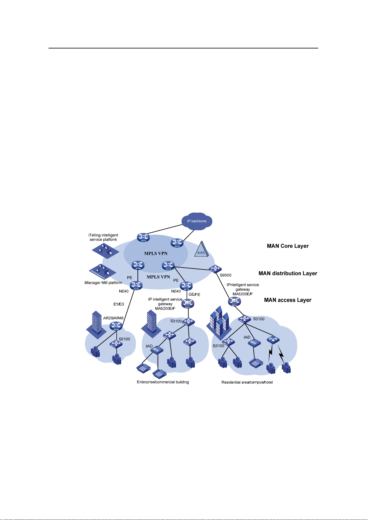
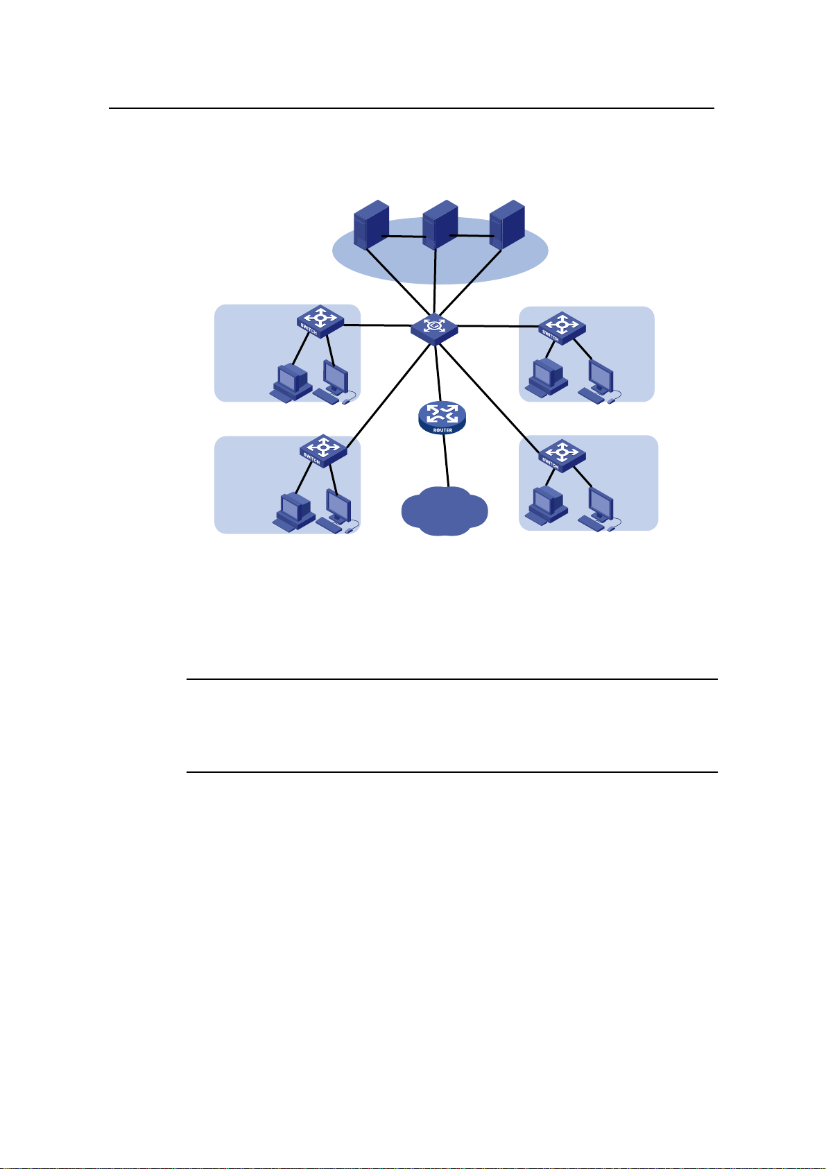
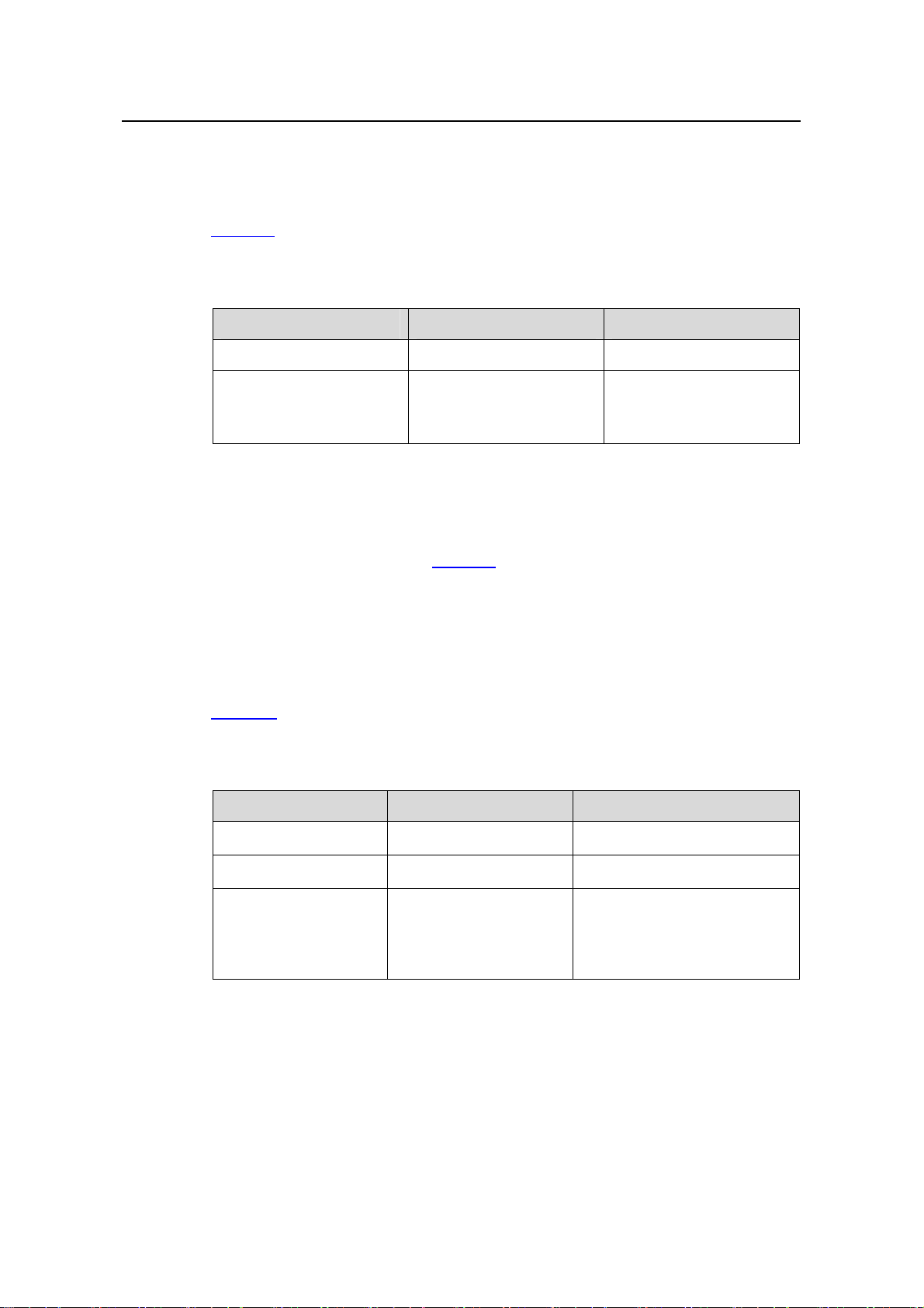
4.1 MAN Access Solution
In a metropolitan area network (MAN), the S3100 series can serve as access devices.
In the downlink direction, they directly connect to users through 100 Mbps interfaces;
and in the uplink direction, they connect to an aggregation layer (Layer 3) switches or
MA5200 intelligent service gateways, which further connect to the core of the MAN
through routers. This provides you a comprehensive gigabit-to-backbone
100-Mbps-to-desktop MAN solution.
Figure 4-1 Network diagram for a MAN using S3100 series
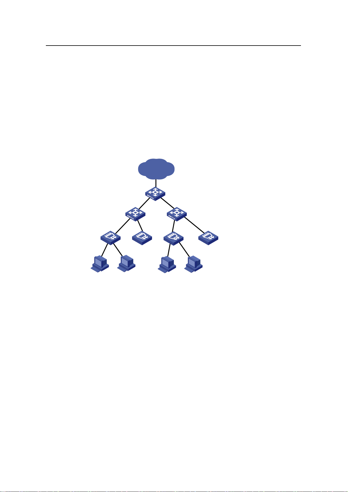
4.2 Education Network Solution
In a campus network, the S3100 series can serve as desktop switching devices at the
access layer. They directly connect to users in education buildings through 100 Mbps
downlink interfaces; and connect to the core switch in the campus throu gh a 1000 Mbps
uplink interface; the core switch further connects to the education network through a
4-1
Page 17
Operation Manual – Product Overview
H3C S3100 Series Ethernet Switches Chapter 4 Network Design
router. This enables the users in the campus to exchange information and share
resources in the scope of the education network.
Sever CoursewareNMS
Network center
1000/100M
S3100
100M
Video classroom/conference room
S3100
100M
1000M 1000M
1000M 1000M
AR28
S5600
Education
network
Classroom/laboratory
Figure 4-2 Network diagram for an education network using S3100 series
4.3 Multi-Service Carrier VLAN Solution
Note:
S3100
100M
School building
S3100
100M
School building
Only S3100-EI series Ethernet switches support this multi-service carrier VLAN
solution.
With development of various application technologies, enterprise users are
increasingly relying on network services. They hope the networks can offer secure,
reliable leased lines, VOIP and video conference services, thus reducing their
operating costs. Additionally, apart from simple Internet surfing, individual users expect
more abundant services from the networks, e.g., IPTV, video chatting, real-time gaming,
etc. Meanwhile, construction of the NGN/3G carrier network will draw huge attention of
carriers. If NGN/3G services can be carried on the broadband access network, the
costs of the entire network solution can be lowered dramatically.
T o carry such services with different QOS requi rements, the broadband access netwo rk
needs to have effective service identification and isolation capacity. VLAN is the best
service identification and isolation technology at present, and is the basis for
4-2
Page 18
Operation Manual – Product Overview
H3C S3100 Series Ethernet Switches Chapter 4 Network Design
multi-service deployment. As broadband users increase explosively and services
appear continuously, however, the traditional VLAN technology cannot meet the
requirements of service deployments. In this situation, QinQ, VLAN mapping, etc
become new choices.
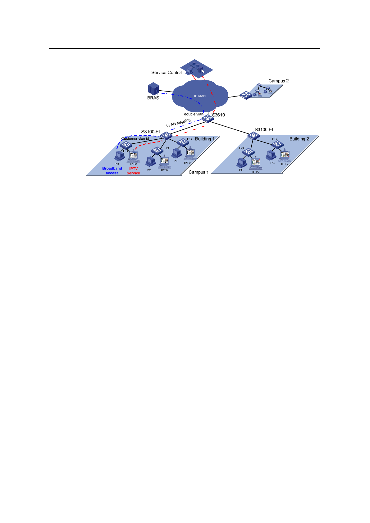
The figure below shows a typical application: The IPTV service requires that the
DSLAM be moved downwards into the campus to enhance users’ access bandwidth.
S3100-EI acts as the DSLAM convergence switch. Selective QinQ is configured on the
device, with the service VLAN identifying the DSLAM or the campus position and the
customer VLAN identifying the customer. In this way, carriers can implement uniform
planning and precise management: VLAN layout is simple, and is not affected by the
customer side.
IP MAN
End office Switch
Campus Switch
(S3100-EI)
DSLAM
…… ……
Figure 4-3 DSLAM convergence application
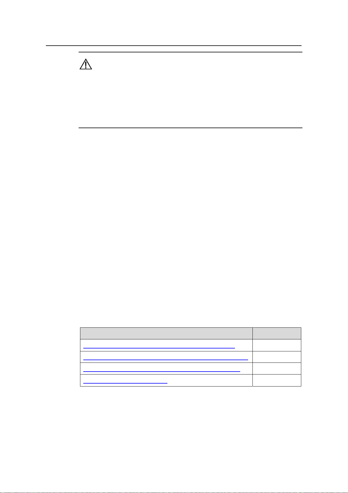
Another more complicated configuration example is when the LAN is connected to
dense Home Gateways (HG). Generally, the ex-factory setting of an HG is simple as it
uses a fixed VLAN tag to identify the attached service type (data service, IPTV, etc).
Thus, precise division and management for users and services can be implemented.
And VLAN mapping is then implemented on the access device S3100-EI. In this way,
respective service VLANs are “translated” into the VLANs that com ply with the carrier’s
deployment. In addition, QinQ is used on the upstream device to identify the campus
position. Such uniform configuration implements carriers’ precise PUPSPV (respective
users and respective services use their own VLANs) management.
4-3
Page 19
Operation Manual – Product Overview
H3C S3100 Series Ethernet Switches Chapter 4 Network Design
Figure 4-4 New vlan management scheme
4-4
Page 20

Operation Manual – CLI
H3C S3100 Series Ethernet Switches Table of Contents
Table of Contents
Chapter 1 CLI Configuration ........................................................................................................ 1-1
1.1 Introduction to the CLI ....................................................................................................... 1-1
1.2 Command Hierarchy..........................................................................................................1-1
1.2.1 Command Level and User Privilege Level..............................................................1-1
1.2.2 Modifying the Command Level................................................................................1-2
1.2.3 Switching User Level............................................................................................... 1-3
1.3 CLI Views...........................................................................................................................1-7
1.4 CLI Features....................................................................................................................1-12
1.4.1 Online Help............................................................................................................1-12
1.4.2 Terminal Display....................................................................................................1-13
1.4.3 Command History..................................................................................................1-13
1.4.4 Error Prompts........................................................................................................ 1-14
1.4.5 Command Edit.......................................................................................................1-15
i
Page 21

Operation Manual – CLI
H3C S3100 Series Ethernet Switches Chapter 1 CLI Configuration
Chapter 1 CLI Configuration
1.1 Introduction to the CLI
A command li ne interface (CLI) is a user interfa ce to interact with a switch. Throug h the
CLI on a switch, a user can enter commands to configure the switch and check output
information to verify the configuration. Each S3100 series Ethernet switch provides an
easy-to-use CLI and a set of configuration commands for the convenience of the user
to configure and manage the switch.
The CLI on S3100 series Ethernet switches provides the following features, and so has
good manageability and operability.
z Hierarchical command protection: After users of different levels log in, they can
only use commands at their own, or lower, levels. This prevents users from using
unauthorized commands to configure switches.
z Online help: Users can gain online help at any time by entering a question mark
(?).
z Debugging: Abundant and detailed debugging information is provided to help
users diagnose and locate network problems.
z Command history function: This enables users to check the commands that they
have lately executed and re-execute the commands.
z Partial matching of commands: The system will use partially matching method to
search for commands. This allows users to execute a command by entering
partially-spelled command keywords as long as the keywords entered can be
uniquely identified by the system.
1.2 Command Hierarchy
1.2.1 Command Level and User Privilege Level
I. Command level
The S3100 series Ethernet switches use hierarchical command protection for
command lines, so as to inhibit users at lower levels from using higher-level command s
to configure the switches.
Based on user privilege, commands are classified into four levels, which default to:
z Visit level (level 0): Commands at this level are mainly used to diagnose network,
and they cannot be saved in configuration file. For example, ping, tracert and
telnet are level 0 commands.
1-1
Page 22

Operation Manual – CLI
H3C S3100 Series Ethernet Switches Chapter 1 CLI Configuration
z Monitor level (level 1): Commands at this level are mainly used to maintain the
system and diagnose service faults, and they cannot be saved in configuration fil e.
Such commands include debugging and terminal.
z System level (level 2): Commands at this level are mainly used to configure
services. Commands concerning routing and network layers are at this level.
These commands can be used to provide network services directly.
z Manage level (level 3): Commands at this level are associated with the basic
operation modules and support modules of the system. These commands p rovide
support for services. Commands concerning file system, FTP/TFTP/XModem
downloading, user management, and level setting are at this level.
II. User privilege level
Users logged into the switch fall into four user privilege levels, which correspond to the
four command levels respectively. Users at a specific level can only use the commands
at the same level or lower levels.
By default, the Console user (a user who logs into the switch through the Console port)
is a level-3 user, and Telnet users are level-0 users.
Y ou can use the user privilege level command to set the default user privilege level for
users logging in through a certain user interface. For details, refer to Login Operation.
Note:
If a user logs in using AAA authentication, the user privilege level depends on the
configuration of the AAA scheme. For details, refer to AAA Operation.
1.2.2 Modifying the Command Level
I. Modifying the Command Level
Commands fall into four levels: visit (level 0), monitor (level 1), system (level 2), and
manage (level 3). By using the following command, the administrator can change the
level of a command in a specific view as required.
Table 1-1 Set the level of a command in a specific view
Operation Command Remarks
Enter system view
Configure the level of a
command in a specific view
system-view
command-privilege level level view
view command
1-2
—
Required
Page 23
Operation Manual – CLI
H3C S3100 Series Ethernet Switches Chapter 1 CLI Configuration
Caution:
z It is recommended not to change the level of a command arbitrarily, for it may cause
inconvenience to maintenance and operation.
z When you change the level of a command with multiple keywords, you should input
the keywords one by one in the order they appear in the command syntax.
Otherwise, your configuration will not take effect.
II. Configuration example
The network administrator (a level 3 user) wants to change some TFTP commands
(such as tftp get) from level 3 to level 0, so that general Telnet users (level 0 users) are
able to download files through TFTP.
# Change the tftp get command in user view (shell) from level 3 to level 0. (Originally,
only level 3 users can change the level of a command.)
<Sysname> system-view
[Sysname] command-privilege level 0 view shell tftp
[Sysname] command-privilege level 0 view shell tftp 192.168.0.1
[Sysname] command-privilege level 0 view shell tftp 192.168.0.1 get
[Sysname] command-privilege level 0 view shell tftp 192.168.0.1 get
bootrom.btm
After the above configuration, general Telnet users can use the tftp get command to
download file bootrom.btm and other files from TFTP server 192.168.0.1 and other
TFTP servers.
1.2.3 Switching User Level
Table 1-2 User level switching configuration task list
Specifying the authentication mode for user level switching Optional
Adopting super password authentication for user level switching Required
Adopting HWTACACS authentication for user level switching Required
Switching to a specific user level Required
Operation Remarks
I. Specifying the authentication mode for user level switching
You can switch between user levels through corresponding commands after logging
into a switch successfully. The high-to-low user level switching is unlimited. However,
the low-to-high user level switching requires the corresponding authentication. The
1-3
Page 24

Operation Manual – CLI
H3C S3100 Series Ethernet Switches Chapter 1 CLI Configuration
super password authentication mode and HWTACACS authentication mode are
available at the same time to provide authentication redundancy.
The configuration of authentication mode for user level switching is performed by
Level-3 users, as described in
Table 1-3.
Table 1-3 Specify the authentication mode for user level switching
Operation Command Remarks
Enter system view
Enter user interface view
Super password
authentication
HWTACACS
authentication
Super password
Specify the
authentication
mode for user
level
switching
authentication
preferred (with the
HWTACACS
authentication as the
backup authentication
mode)
HWTACACS
authentication
preferred (with the
super password
authentication as the
backup authentication
mode)
system-view
user-interface [ type ]
first-number
[ last-number ]
super
authentication-mode
super-password
super
authentication-mode
scheme
super
authentication-mode
super-password
scheme
super
authentication-mode
scheme
super-password
—
—
Optional
By default,
super
password
authentication
is adopted for
user level
switching.
Note:
When both the super password authentication and the HWTACACS authentication are
specified, the device adopts the preferred authentication mode first. If the preferred
authentication mode cannot be implemented (for example, the super password is not
configured or the HWTACACS authentication server is unreachable), the backup
authentication mode is adopted.
II. Adopting super password authentication for user level switching
With the super password set, you can pass the super password authentication
successfully only when you provide the super password as prompted. If no super
1-4
Page 25
Operation Manual – CLI
H3C S3100 Series Ethernet Switches Chapter 1 CLI Configuration
password is set, the system prompts “%Password is not set” when you attempt to
switch to a higher user level. In this case, you cannot pass the super password
authentication.
Table 1-4 lists the operations to configure super password authentication for user level
switching, which can only be performed by level-3 users.
Table 1-4 Set a password for use level switching
Operation Command Remarks
Enter system view
Set the super password
for user level switching
system-view
super password [ level
level ] { cipher | simple }
password
—
Required
By default, the super
password is not set.
III. Adopting HWTACACS authentication for user level switching
To implement HWTACACS authentication for user level switching, a level-3 user must
perform the commands listed in
Table 1-5 to configure the HWTACACS authentication
scheme used for low-to-high user level switching. With HWTACACS authentication
enabled, you can pass the HWTACACS authentication successfully only after you
provide the right user name and the corresponding password as pr ompted. Note that if
you have passed the HWTACACS authentication when logging in to the switch, only
the password is required.
Table 1-5 lists the operations to configure HWTACACS authentication for user level
switching, which can only be performed by Level-3 users.
Table 1-5 Set the HWTACACS authentication scheme for user level switching
Operation Command Description
Enter system view
Enter ISP domain view
Set the HWTACACS
authentication scheme
for user level switching
system-view
domain domain-name
authentication super
hwtacacs-scheme
hwtacacs-scheme-name
1-5
—
—
Required
By default, the HWTACACS
authentication scheme for user
level switching is not set.
Page 26

Operation Manual – CLI
H3C S3100 Series Ethernet Switches Chapter 1 CLI Configuration
Note:
When setting the HWTACACS authentication scheme for user level switchin g using the
authentication super hwtacacs-scheme command, make sure the HWTACACS
authentication scheme identified by the hwtacacs-scheme-name argument already
exists. Refer to AAA Operation for information about HWTACACS authentication
scheme.
IV. Switching to a specific user level
Table 1-6 Switch to a specific user level
Operation Command Remarks
Switch to a specified user
level
super [ level ]
Required
Execute this command in user view.
Note:
z If no user level is specified in the super password command or the super
command, level 3 is used by default.
z For security purpose, the password entered is not displayed when you switch to
another user level. You will remain at the original user level if you have tried three
times but failed to enter the correct authentication information.
V. Configuration example
After a general user telnets to the switch, his/her user level is 0. Now, the network
administrator wants to allow general users to switch to level 3, so that they are able to
configure the switch.
1) Super password authentication co nfiguration example
# A level 3 user sets a switching password for user level 3.
<Sysname> system-view
[Sysname] super password level 3 simple 123
# A general user telnet s to the switch, and then uses the set p assword to switch to user
level 3.
<Sysname> super 3
Password:
User privilege level is 3, and only those commands can be used
whose level is equal or less than this.
Privilege note: 0-VISIT, 1-MONITOR, 2-SYSTEM, 3-MANAGE
1-6
Page 27

Operation Manual – CLI
H3C S3100 Series Ethernet Switches Chapter 1 CLI Configuration
# Af ter configuring the switch, the general user switches back to user level 0.
<Sysname> super 0
User privilege level is 0, and only those commands can be used
whose level is equal or less than this.
Privilege note: 0-VISIT, 1-MONITOR, 2-SYSTEM, 3-MANAGE
2) HWTACACS authentication configuration example
# Configure a HWTACACS authentication scheme named acs, and specify the user
name and password used for user level switching on the HWTACACS server defined in
the scheme. Refer to AAA Operation for detailed configuration procedures.
# Enable HWTACACS authentication for VTY 0 user level switching.
<Sysname> system-view
[Sysname] user-interface vty 0
[Sysname-ui-vty0] super authentication-mode scheme
[Sysname-ui-vty0] quit
# Specify to adopt the HWTACACS authentication scheme named acs for user level
switching in the ISP domain named system.
[Sysname] domain system
[Sysname-isp-system] authentication super hwtacacs-scheme acs
# Switch to user level 3 (assuming that you log into the switch as a VTY 0 user by
Telnet).
<Sysname> super 3
Username: user@system
Password:
User privilege level is 3, and only those commands can be used
whose level is equal or less than this.
Privilege note: 0-VISIT, 1-MONITOR, 2-SYSTEM, 3-MANAGE
1.3 CLI Views
CLI views are designed for different configuration tasks. They are both correlated and
distinguishing. For example, once a user logs into a switch successfully , the user enters
user view, where the user can perform some simple operations such as checking the
operation status and statistics information of the switch. After executing the
system-view command, the user enters system view, where the user can go to other
views by entering corresponding commands.
Table 1-7 lists the CLI views provided by S3100 series Ethernet switches, operations
that can be performed in different CLI views and the commands used to enter specific
CLI views.
1-7
Page 28

Operation Manual – CLI
H3C S3100 Series Ethernet Switches Chapter 1 CLI Configuration
Table 1-7 CLI views
View
User
view
System
view
Ethernet
port view
Available
operation
Display
operation
status and
statistical
information of
the switch
Configure
system
parameters
Configure
Ethernet port
parameters
Prompt
example
<Sysname>
[Sysname]
100 Mbps
Ethernet port
view:
[Sysname-Eth
ernet1/0/1]
1000 Mbps
Ethernet port
view:
[Sysname-Gig
abitEthernet1/
1/1]
Enter method Quit method
Execute the
Enter user view once
logging into the
switch.
quit
command to
log out of the
switch.
Execute the
Execute the
system-view
command in user
view.
quit or
return
command to
return to user
view.
Execute the
Execute the interface
ethernet command in
system view.
quit
command to
return to
system view.
Execute the
return
Execute the interface
gigabitethernet
command in system
command to
return to user
view.
view.
Aux1/0/0
port (the
console
port)
view
VLAN
view
VLAN
interface
view
Loopbac
k
interface
view
The S3100
series do not
support
configuration
on port
Aux1/0/0
Configure
VLAN
parameters
Configure
VLAN
interface
parameters,
including the
management
VLAN
parameters
Configure
loopback
interface
parameters
[Sysname-Au
x1/0/0]
[Sysname-vla
n1]
[Sysname-Vla
n-interface1]
[Sysname-Loo
pBack0]
Execute the interface
aux 1/0/0 command in
system view
Execute the vlan
command in system
view.
Execute the interface
Vlan-interface
command in system
view.
Execute the interface
loopback command
in system view.
1-8
Page 29

Operation Manual – CLI
H3C S3100 Series Ethernet Switches Chapter 1 CLI Configuration
View
Available
operation
Prompt
example
Enter method Quit method
NULL
interface
view
Local
user
view
User
interface
view
FTP
client
view
SFTP
client
view
MST
region
view
Configure
NULL
interface
parameters
Configure
local user
parameters
Configure
user interface
parameters
Configure
FTP client
parameters
Configure
SFTP client
parameters
Configure
MST region
parameters
[Sysname-NU
LL0]
[Sysname-lus
er-user1]
[Sysname-ui-a
ux0]
[ftp]
sftp-client>
[Sysname-mst
-region]
Execute the interface
null command in
system view.
Execute the
local-user command
in system view.
Execute the
user-interface
command in system
view.
Execute the ftp
command in user
view.
Execute the sftp
command in system
view.
Execute the stp
region-configuration
command in system
view.
Cluster
view
Public
key view
Public
key
editing
view
Configure
cluster
parameters
Configure the
RSA public
key for SSH
users
Configure the
RSA or DSA
public key for
SSH users
Edit the RSA
public key for
SSH users
Edit the RSA
or DSA public
key for SSH
users
[Sysname-clu
ster]
[Sysname-rsa
-public-key]
[Sysname-pee
r-public-key]
[Sysname-rsa
-key-code]
[Sysname-pee
r-key-code]
Execute the cluster
command in system
view.
Execute the rsa
peer-public-key
command in system
view.
Execute the
public-key peer
command in system
view.
Execute the
public-key-code
begin command in
public key view.
Execute the
peer-public-
key end
command to
return to
system view.
Execute the
public-key-c
ode end
command to
return to
public key
view.
1-9
Page 30

Operation Manual – CLI
H3C S3100 Series Ethernet Switches Chapter 1 CLI Configuration
View
Available
operation
Prompt
example
Enter method Quit method
Basic
ACL
view
Advance
d ACL
view
Layer 2
ACL
view
QoS
profile
view
Define rules
for a basic
ACL (with ID
ranging from
2000 to 2999)
Define rules
for an
advanced
ACL (with ID
ranging from
3000 to 3999)
Define rules
for an layer 2
ACL (with ID
ranging from
4000 to 4999)
Supported by
only
S3100-EI
series
switches
Define QoS
profile
Supported by
only
S3100-EI
series
switches
[Sysname-aclbasic-2000]
[Sysname-acladv-3000]
[Sysname-aclethernetframe
-4000]
[Sysname-qos
-profile-a123]
Execute the acl
number command in
system view.
Execute the acl
number command in
system view.
Execute the acl
number command in
system view.
Execute the
qos-profile command
in system view.
Execute the
quit
command to
return to
system view.
Execute the
return
command to
return to user
view.
RADIUS
scheme
view
ISP
domain
view
HWPing
view
HWTAC
ACS
view
Configure
RADIUS
scheme
parameters
Configure
ISP domain
parameters
Configure
HWPing
parameters
Configure
HWTACACS
parameters
[Sysname-radi
us-1]
[Sysname-ispaaa123.net]
[Sysname-hw
ping-a123-a12
3]
[Sysname-hwt
acacs-a123]
1-10
Execute the radius
scheme command in
system view.
Execute the domain
command in system
view.
Execute the hwping
command in system
view.
Execute the
hwtacacs scheme
command in system
view.
Page 31

Operation Manual – CLI
H3C S3100 Series Ethernet Switches Chapter 1 CLI Configuration
View
Available
operation
Prompt
example
Enter method Quit method
Configure
PoE profile
PoE
profile
view
parameters
Supported by
only
S3100-TP-P
[Sysname-poe
-profile-a123]
Execute the
poe-profile command
in system view.
WR-EI series
switches
Configure
smart link
Smart
link
group
view
group
parameters
Supported by
only
S3100-EI
[Sysname-sml
k-group1]
Execute the
smart-link group
command in system
view.
series
switches
Configure
monitor link
Monitor
link
group
view
group
parameters
Supported by
only
S3100-EI
[Sysname-mtl
k-group1]
Execute the
monitor-link group
command in system
view.
series
switches
Configure
Execute the vlan-vpn
vid command in
Ethernet port view.
The vlan-vpn enable
command should be
first executed.
QinQ
view
QinQ
parameters
Supported by
only
S3100-EI
series
[Sysname-Eth
ernet1/0/1-vid20]
switches
Note:
The shortcut key <Ctrl+Z> is equivalent to the return command.
Execute the
quit
command to
return to
Ethernet port
view.
Execute the
return
command to
return to user
view.
1-11
Page 32

Operation Manual – CLI
H3C S3100 Series Ethernet Switches Chapter 1 CLI Configuration
1.4 CLI Features
1.4.1 Online Help
When configuring the switch, you can use the online help to get related help information.
The CLI provides two types of online help: complete and partial.
I. Complete online help
1) Enter a question mark (?) in any view on your terminal to display all the commands
available in the view and their brief descriptions. The following takes user view as
an example.
<Sysname> ?
User view commands:
boot Set boot option
cd Change current directory
clock Specify the system clock
cluster Run cluster command
copy Copy from one file to another
debugging Enable system debugging functions
delete Delete a file
dir List files on a file system
display Display current system information
<Other information is omitted>
2) Enter a command, a space, and a question mark (?).
If the question mark “?” is at a keyword position in the command, all available keywords
at the position and their descriptions will be displayed on your terminal.
<Sysname> clock ?
datetime Specify the time and date
summer-time Configure summer time
timezone Configure time zone
If the question mark “?” is at an argument position in the command, the description of
the argument will be displayed on your terminal.
[Sysname] interface vlan-interface ?
<1-4094> VLAN interface number
If only <cr> is displayed after you enter “?”, it means no parameter is available at the “?”
position, and you can enter and execute the command directly.
[Sysname] interface vlan-interface 1 ?
<cr>
1-12
Page 33

Operation Manual – CLI
H3C S3100 Series Ethernet Switches Chapter 1 CLI Configuration
II. Partial online help
1) Enter a character/string, and then a question mark (?) next to it. All the co mmands
beginning with the character/string will be displayed on your terminal. For
example:
<Sysname> p?
ping
pwd
2) Enter a command, a space, a character/string and a question mark (?) next to it.
All the keywords beginning with the character/string (if available) are displayed on
your terminal. For example:
<Sysname> display u?
udp
unit
user-interface
users
3) Enter the first several characters of a keyword of a command and then press
<Tab>. If there is a unique keyword beginning with the characters just typed, the
unique keyword is displayed in its complete form. If there are multiple keywords
beginning with the characters, you can have them displayed one by one (in
complete form) by pressing <Tab> repeatedly.
1.4.2 Terminal Display
The CLI provides the screen splitting feature to have display output suspended when
the screen is full. When display output pauses, you can perform the following
operations as needed (see
Table 1-8 Display-related operations
Operation Function
Press <Ctrl+C>
Press any character except <Space>,
<Enter>, /, +, and - when the display
output pauses
Press the space key Get to the next page.
Press <Enter> Get to the next line.
1.4.3 Command History
Table 1-8).
Stop the display output and execution of
the command.
Stop the display output.
The CLI provides the command history function. You can use the display
history-command command to view a specific number of latest executed commands
1-13
Page 34

Operation Manual – CLI
H3C S3100 Series Ethernet Switches Chapter 1 CLI Configuration
and execute them again in a convenient way. By default, the CLI can store up to 10
latest executed commands for each user. You can view the command history by
performing the operations listed in
Table 1-9.
Table 1-9 View history commands
Purpose Operation Remarks
Display the latest
executed history
commands
Recall the previous
history command
Recall the next history
command
Execute the display
history-command
command
Press the up arrow key or
<Ctrl+P>
Press the down arrow key
or <Ctrl+N>
This command displays
the command history.
This operation recalls the
previous history
command (if available).
This operation recalls the
next history command (if
available).
Note:
z The Windows 9x HyperTerminal explains the up and down arrow keys in a different
way, and therefore the two keys are invalid when you access history commands in
such an environment. However, you can use <Ctrl+ P> and <Ctrl+ N> instead to
achieve the same purpose.
z When you enter the same command multiple times consecutively, only one history
command entry is created by the command line interface.
1.4.4 Error Prompts
If a command passes the syntax check, it will be successfully executed; otherwise, an
error message will be displayed.
Table 1-10 Common error messages
Error message Description
Unrecognized command
Incomplete command The command entered is incomplete.
Too many parameters The parameters entered are too many.
Ambiguous command The parameters entered are ambiguous.
Table 1-10 lists the common error messages.
The command does not exist.
The keyword does not exist.
The parameter type is wrong.
The parameter value is out of range.
1-14
Page 35

Operation Manual – CLI
H3C S3100 Series Ethernet Switches Chapter 1 CLI Configuration
Error message Description
Wrong parameter A parameter entered is wrong.
found at '^' position An error is found at the '^' position.
1.4.5 Command Edit
The CLI provides basic command edit functions and supports multi-line editing. The
maximum number of characters a command can contain is 254.
edit operations.
Table 1-11 Edit operations
Press… To…
Insert the corresponding character at the cursor
A common key
position and move the cursor one character to
the right if the command is shorter than 254
characters.
Table 1-11 list s the CLI
Backspace key
Delete the character on the left of the cursor and
move the cursor one character to the left.
Left arrow key or <Ctrl+B> Move the cursor one character to the left.
Right arrow key or <Ctrl+F> Move the cursor one character to the right.
Up arrow key or <Ctrl+P>
Down arrow key or <Ctrl+N>
Display history commands.
Use the partial online help. That is, when you
input an incomplete keyword and press <Tab>,
if the input parameter uniquely identifies a
complete keyword, the system substitutes the
complete keyword for the input parameter; if
<Tab>
more than one keywords match the input
parameter, you can display them one by one (in
complete form) by pressing <Tab> repeatedly; if
no keyword matches the input parameter, the
system displays your original input on a new line
without any change.
1-15
Page 36

Operation Manual – Login
H3C S3100 Series Ethernet Switches Table of Contents
Table of Contents
Chapter 1 Logging into an Ethernet Switch ............................................................................... 1-1
1.1 Logging into an Ethernet Switch........................................................................................1-1
1.2 Introduction to the User Interface ...................................................................................... 1-1
1.2.1 Supported User Interfaces......................................................................................1-1
1.2.2 User Interface Index................................................................................................1-2
1.2.3 Common User Interface Configuration ...................................................................1-2
Chapter 2 Logging in through the Console Port........................................................................2-1
2.1 Introduction........................................................................................................................2-1
2.2 Logging in through the Console Port.................................................................................2-1
2.3 Console Port Login Configuration...................................................................................... 2-4
2.3.1 Common Configuration...........................................................................................2-4
2.3.2 Console Port Login Configurations for Different Authentication Modes..................2-5
2.4 Console Port Login Configuration with Authentication Mode Being None........................2-6
2.4.1 Configuration Procedure.........................................................................................2-6
2.4.2 Configuration Example............................................................................................2-8
2.5 Console Port Login Configuration with Authentication Mode Being Password................. 2-9
2.5.1 Configuration Procedure.........................................................................................2-9
2.5.2 Configuration Example..........................................................................................2-11
2.6 Console Port Login Configuration with Authentication Mode Being Scheme..................2-13
2.6.1 Configuration Procedure.......................................................................................2-13
2.6.2 Configuration Example..........................................................................................2-15
Chapter 3 Logging in through Telnet..........................................................................................3-1
3.1 Introduction........................................................................................................................3-1
3.1.1 Common Configuration...........................................................................................3-1
3.1.2 Telnet Configurations for Different Authentication Modes......................................3-2
3.2 Telnet Configuration with Authentication Mode Being None............................................. 3-4
3.2.1 Configuration Procedure.........................................................................................3-4
3.2.2 Configuration Example............................................................................................3-5
3.3 Telnet Configuration with Authentication Mode Being Password......................................3-6
3.3.1 Configuration Procedure.........................................................................................3-6
3.3.2 Configuration Example............................................................................................3-7
3.4 Telnet Configuration with Authentication Mode Being Scheme ........................................ 3-9
3.4.1 Configuration Procedure.........................................................................................3-9
3.4.2 Configuration Example..........................................................................................3-13
3.5 Telnetting to a Switch ...................................................................................................... 3-14
3.5.1 Telnetting to a Switch from a Terminal .................................................................3-14
3.5.2 Telnetting to another Switch from the Current Switch...........................................3-16
i
Page 37

Operation Manual – Login
H3C S3100 Series Ethernet Switches Table of Contents
Chapter 4 Logging in Using a Modem......................................................................................... 4-1
4.1 Introduction........................................................................................................................4-1
4.2 Configuration on the Switch Side.......................................................................................4-1
4.2.1 Modem Configuration..............................................................................................4-1
4.2.2 Switch Configuration...............................................................................................4-2
4.3 Modem Connection Establishment.................................................................................... 4-2
Chapter 5 Logging in through the Web-based Network Management System....................... 5-1
5.1 Introduction........................................................................................................................5-1
5.2 Establishing an HTTP Connection.....................................................................................5-1
5.3 Configuring the Login Banner............................................................................................ 5-2
5.3.1 Configuration Procedure.........................................................................................5-2
5.3.2 Configuration Example............................................................................................5-3
5.4 Enabling/Disabling the WEB Server..................................................................................5-4
Chapter 6 Logging in through NMS............................................................................................. 6-1
6.1 Introduction........................................................................................................................6-1
6.2 Connection Establishment Using NMS.............................................................................. 6-1
Chapter 7 User Control......................................................................................................... ........7-1
7.1 Introduction........................................................................................................................7-1
7.2 Controlling Telnet Users....................................................................................................7-1
7.2.1 Prerequisites ...........................................................................................................7-1
7.2.2 Controlling Telnet Users by Source IP Addresses..................................................7-2
7.2.3 Controlling Telnet Users by Source and Destination IP Addresses........................7-2
7.2.4 Controlling Telnet Users by Source MAC Addresses.............................................7-3
7.2.5 Configuration Example............................................................................................7-4
7.3 Controlling Network Management Users by Source IP Addresses................................... 7-4
7.3.1 Prerequisites ...........................................................................................................7-5
7.3.2 Controlling Network Management Users by Source IP Addresses ........................ 7-5
7.3.3 Configuration Example............................................................................................7-6
7.4 Controlling Web Users by Source IP Address...................................................................7-6
7.4.1 Prerequisites ...........................................................................................................7-7
7.4.2 Controlling Web Users by Source IP Addresses .................................................... 7-7
7.4.3 Disconnecting a Web User by Force ......................................................................7-7
7.4.4 Configuration Example............................................................................................7-7
ii
Page 38

Operation Manual – Login
H3C S3100 Series Ethernet Switches Chapter 1 Logging into an Ethernet Switch
Chapter 1 Logging into an Ethernet Switch
1.1 Logging into an Ethernet Switch
You can log into an S3100 Ethernet switch in one of the following ways:
z Logging in locally through the Console port
z Logging in locally or remotely through an Ethernet port by means of Telnet or SSH
z Telnetting to the Console port using a modem
z Logging into the Web-based network management system
z Logging in through NMS (network management station)
1.2 Introduction to the User Interface
1.2.1 Supported User Interfaces
Note:
The auxiliary (AUX) port and the Console port of an H3C Ethernet switch are the same
port (refereed to as Console port in the following part). You will be in the AUX user
interface if you log in through this port.
S3100 series Ethernet switches support two types of user interfaces: AUX and V TY.
z AUX user interface: A view when you log in through the AUX port. AUX port is a
line device port.
z Virtual type terminal (VTY) user interface: A view when you log in through VTY.
VTY port is a logical terminal line used when you access the device by means of
Telnet or SSH.
Table 1-1 Description on user interface
User interface Applicable user Port used Description
AUX
Users logging in
through the Console
port
Console port
Each switch can
accommodate one AUX
user.
VTY
Telnet users and
SSH users
1-1
Ethernet port
Each switch can
accommodate up to five
VTY users.
Page 39

Operation Manual – Login
H3C S3100 Series Ethernet Switches Chapter 1 Logging into an Ethernet Switch
1.2.2 User Interface Index
Two kinds of user interface index exist: absolute user interface index and relative user
interface index.
1) The absolute user interface indexes are as follows:
z The absolute AUX user interfaces is numbered 0.
z VTY user interface indexes follow AUX user interface indexes. The first absolute
VTY user interface is numbered 1, the second is 2, and so on.
2) A relative user interface index can be obtained by appending a number to the
identifier of a user interface type. It is generated by user interface type. The
relative user interface indexes are as follows:
z AUX user interfaces is numbered 0.
z VTY user interfaces are numbered VTY0, VTY1, and so on.
1.2.3 Common User Interface Configuration
Table 1-2 Common user interface configuration
Operation Command Description
Optional
Lock the current user
interface
lock
Execute this command in user
view.
A user interface is not locked
by default.
Specify to send
messages to all user
interfaces/a specified
send { all | number |
type number }
user interface
Free a user interface
Enter system view
free user-interface
[ type ] number
system-view
header [ incoming |
Set the banner
legal | login | shell ]
text
Set a system name for
the switch
sysname string
Optional
Execute this command in user
view.
Optional
Execute this command in user
view.
—
Optional
By default, no banner is
configured
Optional
By default, the system name
is H3C.
Enable copyright
information displaying
copyright-info enable
Optional
By default, copyright
displaying is enabled. That is,
the copy right information is
displayed on the terminal after
a user logs in successfully.
1-2
Page 40

Operation Manual – Login
H3C S3100 Series Ethernet Switches Chapter 1 Logging into an Ethernet Switch
Operation Command Description
Enter user interface
view
user-interface [ type ]
first-number
[ last-number ]
Display the information
about the current user
interface/all user
display users [ all ]
interfaces
Display the physical
attributes and
configuration of the
current/a specified user
display user-interface
[ type number | number ]
interface
Display the information
about the current web
display web users
users
—
Optional
You can execute the display
command in any view.
1-3
Page 41

Operation Manual – Login
H3C S3100 Series Ethernet Switches Chapter 2 Logging in through the Console Port
Chapter 2 Logging in through the Console Port
2.1 Introduction
T o log in through the Co nsole port is the most common way to log into a switch. It is also
the prerequisite to configure other login methods. By default, you can locally log into an
S3100 Ethernet switch through its Console port only.
Table 2-1 lists the default settings of a Console port.
Table 2-1 The default settings of a Console port
Setting Default
Baud rate 9,600 bps
Flow control None
Check mode (Parity) None
Stop bits 1
Data bits 8
To log into a switch through the Console port, make sure the settings of both the
Console port and the user terminal are the same.
After logging into a switch, you can perform configuration for AUX users. Refer to
section
2.3 “Console Port Login Configuration” for more.
2.2 Logging in through the Console Port
Following are the procedures to connect to a switch through the Console port.
1) Connect the serial port of your PC/terminal to the Console port of the switch, as
shown in
Figure 2-1 Diagram for connecting to the Console port of a switch
Figure 2-1.
2-1
Page 42

Operation Manual – Login
H3C S3100 Series Ethernet Switches Chapter 2 Logging in through the Console Port
2) If you use a PC to connect to the Console port, launch a terminal emulation utility
(such as Terminal in Windows 3.X or HyperTerminal in Windows 9X/Windows
2000/Windows XP. The following assumes that you are runnin g Windows XP) and
perform the configuration shown in
Figure 2-2 through Figure 2-4 for the
connection to be created. Normally, both sides (that is, the serial port of the PC
and the Console port of the switch) are configured as those listed in
Table 2-1.
Figure 2-2 Create a connection
Figure 2-3 Specify the port used to establish the connection
2-2
Page 43

Operation Manual – Login
H3C S3100 Series Ethernet Switches Chapter 2 Logging in through the Console Port
Figure 2-4 Set port parameters
3) Turn on the switch. You will be prompted to press the Enter key if the switch
successfully completes POST (power-on self test). The prompt (such as <H3C>)
appears after you press the Enter key, as shown in
Figure 2-5.
Figure 2-5 HyperTerminal CLI
4) You can then configure the switch or check the information about the switch by
executing the corresponding commands. You can also acquire h elp by typing the ?
character. Refer to related parts in this manual for information about the
commands used for configuring the switch.
2-3
Page 44

Operation Manual – Login
H3C S3100 Series Ethernet Switches Chapter 2 Logging in through the Console Port
2.3 Console Port Login Configuration
2.3.1 Common Configuration
Table 2-2 lists the common configuration of Console port login.
Table 2-2 Common configuration of Console port login
Configuration Remarks
Console port
configuration
AUX user
interface
configuration
Terminal
configuration
Baud rate
Check mode
Stop bits
Data bits
Configure the
command level
available to the users
logging into the AUX
user interface
Make terminal
services available
Set the maximum
number of lines the
screen can contain
Set history command
buffer size
Optional
The default baud rate is 9,600 bps.
Optional
By default, the check mode of the Console
port is set to “none”, which means no check
bit.
Optional
The default stop bits of a Console port is 1.
Optional
The default data bits of a Console port is 8.
Optional
By default, commands of level 3 are
available to the users logging into the AUX
user interface.
Optional
By default, terminal services are available in
all user interfaces
Optional
By default, the screen can contain up to 24
lines.
Optional
By default, the history command buffer can
contain up to 10 commands.
Set the timeout time
of a user interface
Optional
The default timeout time is 10 minutes.
2-4
Page 45

Operation Manual – Login
H3C S3100 Series Ethernet Switches Chapter 2 Logging in through the Console Port
Caution:
The change to Console port configuration takes effect immediately, so the connection
may be disconnected when you log in through a Console port and then configure this
Console port. To configure a console port, you are recommended to log into the switch
in other ways. To log into a switch through its Console port after you modify the Console
port settings, you need to modify the corresponding settings of the terminal emulation
utility running on your PC accordingly in the dialog box shown in
Figure 2-4.
2.3.2 Console Port Login Configurations for Different Authentication Modes
Table 2-3 lists Console port login configurations for different authentication modes.
Table 2-3 Console port login configurations for different authentication modes
Authentication
mode
None
Password
Console port login
configuration
Perform
common
configuration
Configure
the
password
Perform
common
configuration
Perform common
configuration for
Console port login
Configure the
password for local
authentication
Perform common
configuration for
Console port login
Optional
Refer to
Required
Optional
Refer to
Remarks
Table 2-2.
Table 2-2.
2-5
Page 46

Operation Manual – Login
H3C S3100 Series Ethernet Switches Chapter 2 Logging in through the Console Port
Authentication
mode
Console port login
configuration
Remarks
Scheme
Specify to
perform local
authenticatio
n or remote
RADIUS
authenticatio
n
Configure
user name
and
password
Manage
AUX users
Perform
common
configuration
AAA configuration
specifies whether
to perform local
authentication or
RADIUS
authentication
Configure user
names and
passwords for
local/RADIUS
users
Set service type
for AUX users
Perform common
configuration for
Console port login
Optional
Local authentication is
performed by default.
Refer to the AAA part for
more.
Required
z The user name and
password of a local user
are configured on the
switch.
z The user name and
password of a RADIUS
user are configured on
the RADIUS server.
Refer to user manual of
RADIUS server for more.
Required
Optional
Refer to
Table 2-2.
Note:
Changes made to the authentication mode for Console port login takes effect after you
quit the command-line interface and then log in again.
2.4 Console Port Login Configuration with Authentication Mode Being None
2.4.1 Configuration Procedure
Table 2-4 Console port login configuration with the authentication mode being none
Operation Command Description
Enter system view
Enter AUX user interface
view
system-view
user-interface aux 0 —
—
2-6
Page 47

Operation Manual – Login
H3C S3100 Series Ethernet Switches Chapter 2 Logging in through the Console Port
Operation Command Description
Required
Configure not to
authenticate users
authentication-mode
none
By default, users logging in
through the Console port
(AUX user interface) are not
authenticated.
Set the
baud rate
Set the
check
Configure the
mode
Console port
Set the
stop bits
Set the
data bits
Configure the command
level available to users
logging into the user
interface
speed speed-value
parity { even | none |
odd }
stopbits { 1 | 1.5 | 2 }
databits { 7 | 8 }
user privilege level
level
Optional
The default baud rate of a
Console port is 9,600 bps.
Optional
By default, the check mode
of a Console port is none,
that is, no check is
performed.
Optional
The stop bits of a Console
port is 1.
Optional
The default data bits of a
Console port is 8.
Optional
By default, commands of
level 3 are available to users
logging into the AUX user
interface, and commands of
level 0 are available to users
logging into the VTY user
interface.
Enable terminal services
Set the maximum number
of lines the screen can
contain
Set the history command
buffer size
shell
screen-length
screen-length
history-command
max-size value
2-7
Optional
By default, terminal services
are available in all user
interfaces.
Optional
By default, the screen can
contain up to 24 lines.
You can use the
screen-length 0 command
to disable the function to
display information in pages.
Optional
The default history command
buffer size is 10. That is, a
history command buffer can
store up to 10 commands by
default.
Page 48

Operation Manual – Login
H3C S3100 Series Ethernet Switches Chapter 2 Logging in through the Console Port
Operation Command Description
Optional
The default timeout time of a
user interface is 10 minutes.
With the timeout time being
10 minutes, the connection to
Set the timeout time for
the user interface
idle-timeout minutes
[ seconds ]
a user interface is terminated
if no operation is performed
in the user interface within 10
minutes.
Y ou can use the idle-timeout
0 command to disable the
timeout function.
2.4.2 Configuration Example
I. Network requirements
Assume that the switch is configured to allow users to log in through Telnet, and the
user level is set to the administrator level (level 3). Perform the following configurations
for users logging in through the Console port (AUX user interface).
z Do not authenticate the users.
z Commands of level 2 are available to the users logging into the AUX user
interface.
z The baud rate of the Console port is 19,200 bps.
z The screen can contain up to 30 lines.
z The history command buffer can contain up to 20 commands.
z The timeout time of the AUX user interface is 6 minutes.
II. Network diagram
Ethernet1/0/1
Ethernet
User PC running Telnet
Figure 2-6 Network diagram for AUX user interface configuration (with the
authentication mode being none)
2-8
Page 49

Operation Manual – Login
H3C S3100 Series Ethernet Switches Chapter 2 Logging in through the Console Port
III. Configuration procedure
# Enter system view.
<Sysname> system-view
# Enter AUX user interface view.
[Sysname] user-interface aux 0
# Specify not to authenticate users logging in through the Console port.
[Sysname-ui-aux0] authentication-mode none
# Specify commands of level 2 are available to users logging into the AUX user
interface.
[Sysname-ui-aux0] user privilege level 2
# Set the baud rate of the Console port to 19,200 bps.
[Sysname-ui-aux0] speed 19200
# Set the maximum number of lines the screen can contain to 30.
[Sysname-ui-aux0] screen-length 30
# Set the maximum number of commands the history comm and bu ffer can store to 20.
[Sysname-ui-aux0] history-command max-size 20
# Set the timeout time of the AUX user interface to 6 minute s.
[Sysname-ui-aux0] idle-timeout 6
After the above configuration, you need to modify the configuration of the terminal
emulation utility running on the PC accordingly in the dialog box shown in
Figure 2-4 to
log into the switch successfully.
2.5 Console Port Login Configuration with Authentication Mode Being Password
2.5.1 Configuration Procedure
Table 2-5 Console port login configuration with the authentication mode being
password
Operation Command Description
Enter system view
Enter AUX user
interface view
system-view
user-interface aux 0—
—
2-9
Page 50

Operation Manual – Login
H3C S3100 Series Ethernet Switches Chapter 2 Logging in through the Console Port
Operation Command Description
Required
Configure to
authenticate users
using the local
authentication-mod
e password
password
By default, users logging into a
switch through the Console port
are not authenticated; while
those logging in through
Modems or Telnet are
authenticated.
set authentication
Set the local password
password { cipher |
Required
simple } password
Optional
Set the
baud rate
speed speed-value
The default baud rate of an AUX
port (also the Console port) is
9,600 bps.
Set the
Configure
the
check
mode
Console
port
Set the
stop bits
Set the
data bits
Configure the command
level available to users
logging into the user
interface
Make terminal services
available to the user
interface
Set the maximum
number of lines the
screen can contain
parity { even | none |
odd }
stopbits { 1 | 1.5 | 2 }
databits { 7 | 8 }
user privilege level
level
shell
screen-length
screen-length
Optional
By default, the check mode of a
Console port is set to none, that
is, no check bit.
Optional
The default stop bits of a
Console port is 1.
Optional
The default data bits of a
Console port is 8.
Optional
By default, commands of level 3
are available to users logging
into the AUX user interface.
Optional
By default, terminal services are
available in all user interfaces.
Optional
By default, the screen can
contain up to 24 lines.
You can use the screen-length
0 command to disable the
function to display information in
pages.
Set history command
buffer size
history-command
max-size value
2-10
Optional
The default history command
buffer size is 10. That is, a
history command buffer can
store up to 10 commands by
default.
Page 51

Operation Manual – Login
H3C S3100 Series Ethernet Switches Chapter 2 Logging in through the Console Port
Operation Command Description
Optional
The default timeout time of a
user interface is 10 minutes.
With the timeout time being 10
Set the timeout time for
the user interface
idle-timeout minutes
[ seconds ]
minutes, the connection to a
user interface is terminated if no
operation is performed in the
user interface within 10 minutes.
You can use the idle-timeout 0
command to disable the timeout
function.
2.5.2 Configuration Example
I. Network requirements
Assume the switch is configured to allow users to log in through Telnet, and the user
level is set to the administrator level (level 3). Perform the following configurations for
users logging in through the Console port (AUX user interface).
z Authenticate the users using passwords.
z Set the local password to 123456 (in plain text).
z The commands of level 2 are available to the users.
z The baud rate of the Console port is 19,200 bps.
z The screen can contain up to 30 lines.
z The history command buffer can store up to 20 commands.
z The timeout time of the AUX user interface is 6 minutes.
II. Network diagram
Ethernet1/0/1
Ethernet
User PC running Telnet
Figure 2-7 Network diagram for AUX user interface configuration (with the
authentication mode being password)
2-11
Page 52

Operation Manual – Login
H3C S3100 Series Ethernet Switches Chapter 2 Logging in through the Console Port
III. Configuration procedure
# Enter system view.
<Sysname> system-view
# Enter AUX user interface view.
[Sysname] user-interface aux 0
# Specify to authenticate users logging in through the Console port using the local
password.
[Sysname-ui-aux0] authentication-mode password
# Set the local password to 123456 (in plain text).
[Sysname-ui-aux0] set authentication password simple 123456
# Specify commands of level 2 are available to users logging into the AUX user
interface.
[Sysname-ui-aux0] user privilege level 2
# Set the baud rate of the Console port to 19,200 bps.
[Sysname-ui-aux0] speed 19200
# Set the maximum number of lines the screen can contain to 30.
[Sysname-ui-aux0] screen-length 30
# Set the maximum number of commands the history comm and bu ffer can store to 20.
[Sysname-ui-aux0] history-command max-size 20
# Set the timeout time of the AUX user interface to 6 minute s.
[Sysname-ui-aux0] idle-timeout 6
After the above configuration, you need to modify the configuration of the terminal
emulation utility running on the PC accordingly in the dialog box shown in
Figure 2-4 to
log into the switch successfully.
2-12
Page 53

Operation Manual – Login
H3C S3100 Series Ethernet Switches Chapter 2 Logging in through the Console Port
2.6 Console Port Login Configuration with Authentication Mode Being Scheme
2.6.1 Configuration Procedure
Table 2-6 Console port login configuration with the authentication mode being scheme
Operation Command Description
Enter system view
Enter the
default ISP
domain view
Specify the
AAA scheme
to be applied
Configur
e the
authentic
ation
mode
to the
domain
Quit to
system view
system-view
domain
domain-name
scheme { local |
none |
radius-scheme
radius-scheme-name
[ local ] |
hwtacacs-scheme
hwtacacs-scheme-na
me [ local ] }
quit
—
Optional
By default, the local AAA
scheme is applied.
If you specify to apply the local
AAA scheme, you need to
perform the configuration
concerning local user as well.
If you specify to apply an
existing scheme by providing
the radius-scheme-name
argument, you need to perform
the following configuration as
well:
z Perform AAA&RADIUS
configuration on the switch.
(Refer to the AAA part for
more.)
z Configure the user name
and password accordingly
on the AAA server. (Refer to
the user manual of AAA
server.)
Create a local user (Enter
local user view.)
Set the authentication
password for the local
user
Specify the service type
for AUX users
Quit to system view
Enter AUX user interface
view
local-user
user-name
password { simple |
cipher } password
service-type
terminal [ level
level ]
quit
user-interface aux 0—
2-13
Required
No local user exists by default.
Required
Required
—
Page 54

Operation Manual – Login
H3C S3100 Series Ethernet Switches Chapter 2 Logging in through the Console Port
Operation Command Description
Required
The specified AAA scheme
determines whether to
authenticate users locally or
remotely.
By default, users logging in
Configure to authenticate
users locally or remotely
authentication-mod
e scheme
[ commandauthorization ]
through the Console port (AUX
user interface) are not
authenticated.
Optional
Set the
baud rate
speed speed-value
The default baud rate of the
AUX port (also the Console
port) is 9,600 bps.
Optional
Configure
the
Console
port
Set the
check mode
Set the stop
bits
parity { even | none |
odd }
stopbits { 1 | 1.5 | 2 }
By default, the check mode of a
Console port is set to none,
that is, no check bit.
Optional
The default stop bits of a
Console port is 1.
Set the data
bits
databits { 7 | 8 }
Configure the command
level available to users
logging into the user
user privilege level
level
interface
Make terminal services
available to the user
shell
interface
Set the maximum
number of lines the
screen can contain
Set history command
buffer size
screen-length
screen-length
history-command
max-size value
Optional
The default data bits of a
Console port is 8.
Optional
By default, commands of level 3
are available to users logging
into the AUX user interface.
Optional
By default, terminal services
are available in all user
interfaces.
Optional
By default, the screen can
contain up to 24 lines.
You can use the screen-length
0 command to disable the
function to display information
in pages.
Optional
The default history command
buffer size is 10. That is, a
history command buffer can
store up to 10 commands by
default.
2-14
Page 55

Operation Manual – Login
H3C S3100 Series Ethernet Switches Chapter 2 Logging in through the Console Port
Operation Command Description
Optional
The default timeout time of a
user interface is 10 minutes.
With the timeout time being 10
minutes, the connection to a
Set the timeout time for
the user interface
idle-timeout minutes
[ seconds ]
user interface is terminated if
no operation is performed in the
user interface within 10
minutes.
You can use the idle-timeout 0
command to disable the
timeout function.
Note that if you configure to authenticate the users in the scheme mode, the command
level available to users logging into a switch depends on the command level specified
in the service-type terminal [ level level ] command.
2.6.2 Configuration Example
I. Network requirements
Assume the switch is configured to allow users to log in through Telnet, and the user
level is set to the administrator level (level 3). Perform the following configurations for
users logging in through the console port (AUX user interface).
z Configure the local user name as “guest”.
z Set the authentication password of the local user to 123456 (in plain text).
z Set the service type of the local user to Terminal and the command level to 2.
z Configure to authenticate the users in the scheme mode.
z The baud rate of the Console port is 19,200 bps.
z The screen can contain up to 30 lines.
z The history command buffer can store up to 20 commands.
z The timeout time of the AUX user interface is 6 minutes.
2-15
Page 56
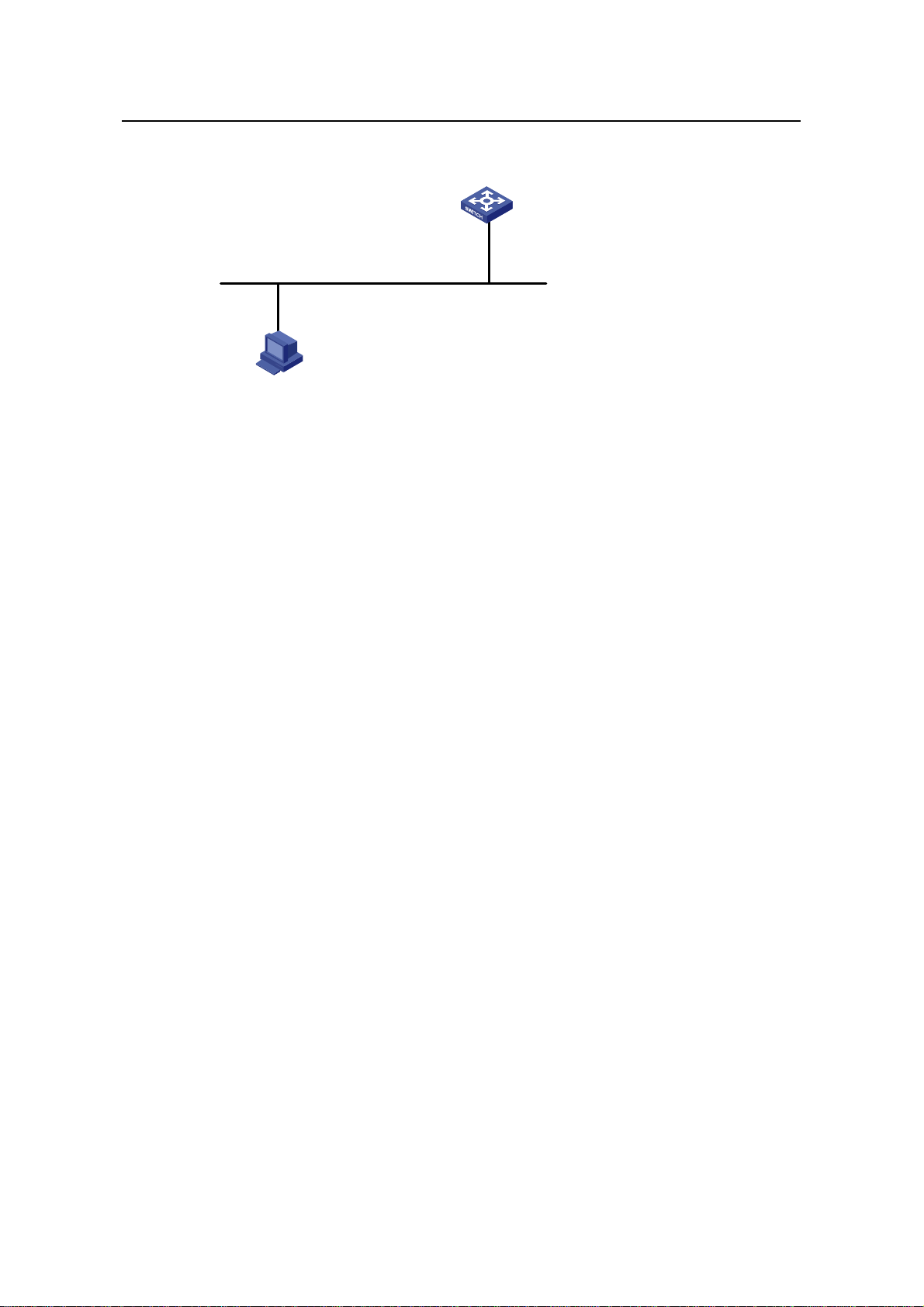
Operation Manual – Login
H3C S3100 Series Ethernet Switches Chapter 2 Logging in through the Console Port
II. Network diagram
Ethernet1/0/1
Ethernet
User PC running Telnet
Figure 2-8 Network diagram for AUX user interface configuration (with the
authentication mode being scheme)
III. Configuration procedure
# Enter system view.
<Sysname> system-view
# Create a local user named guest and enter local user view.
[Sysname] local-user guest
# Set the authentication password to 123456 (in plain text).
[Sysname-luser-guest] password simple 123456
# Set the service type to Terminal, Specify commands of level 2 are available to users
logging into the AUX user interface.
[Sysname-luser-guest] service-type terminal level 2
[Sysname-luser-guest] quit
# Enter AUX user interface view.
[Sysname] user-interface aux 0
# Configure to authenticate users logging in through the Console port in the scheme
mode.
[Sysname-ui-aux0] authentication-mode scheme
# Set the baud rate of the Console port to 19,200 bps.
[Sysname-ui-aux0] speed 19200
# Set the maximum number of lines the screen can contain to 30.
[Sysname-ui-aux0] screen-length 30
# Set the maximum number of commands the history comm and bu ffer can store to 20.
[Sysname-ui-aux0] history-command max-size 20
# Set the timeout time of the AUX user interface to 6 minute s.
2-16
Page 57

Operation Manual – Login
H3C S3100 Series Ethernet Switches Chapter 2 Logging in through the Console Port
[Sysname-ui-aux0] idle-timeout 6
After the above configuration, you need to modify the configuration of the terminal
emulation utility running on the PC accordingly in the dialog box shown in
Figure 2-4 to
log into the switch successfully.
2-17
Page 58

Operation Manual – Login
H3C S3100 Series Ethernet Switches Chapter 3 Logging in through Telnet
Chapter 3 Logging in through Telnet
3.1 Introduction
S3100 series Ethernet switches support Telnet. Y ou can manage and maintai n a switch
remotely by Telnetting to the switch.
To log into a switch through Telnet, the corresponding configuration is required on both
the switch and the Telnet terminal.
You can also log into a switch through SSH. SSH is a secure shell added to Telnet.
Refer to the SSH Operation for related information.
Table 3-1 Requirements for Telnetting to a switch
Item Requirement
The IP address is configured for the VLAN of the switch, and the
route between the switch and the Telnet terminal is reachable.
Switch
(Refer to the IP Address Configuration – IP Performance
Configuration and Routing Protocol parts for more.)
The authentication mode and other settings are configured. Refer
Table 3-2 and Table 3-3.
to
Telnet terminal
Note:
Telnetting to a switch using IPv6 protocols is similar to Telnetting to a switch usi ng IPv4
protocols. Refer to the IPv6 Management part for related information.
Telnet is running.
The IP address of the VLAN of the switch is available.
3.1.1 Common Configuration
Table 3-2 lists the common Telnet configuration.
3-1
Page 59

Operation Manual – Login
H3C S3100 Series Ethernet Switches Chapter 3 Logging in through Telnet
Table 3-2 Common Telnet configuration
Configuration Description
Configure the command
level available to users
logging into the VTY user
interface
VTY user
interface
configuration
Configure the protocols the
user interface supports
Set the commands to be
executed automatically
after a user log into the
user interface successfully
Make terminal services
available
Set the maximum number
of lines the screen can
VTY terminal
contain
configuration
Set history command
buffer size
Optional
By default, commands of level 0 are
available to users logging into a VTY
user interface.
Optional
By default, Telnet and SSH protocol
are supported.
Optional
By default, no command is executed
automatically after a user logs into the
VTY user interface.
Optional
By default, terminal services are
available in all user interfaces
Optional
By default, the screen can contain up
to 24 lines.
Optional
By default, the history command buffer
can contain up to 10 commands.
Set the timeout time of a
user interface
Optional
The default timeout time is 10 minutes.
3.1.2 Telnet Configurations for Different Authentication Modes
Table 3-3 lists Telnet configurations for different authentication modes.
Table 3-3 Telnet configurations for different authentication modes
Authenticati
on mode
None
Password
Perform
common
configuration
Configure the
password
Perform
common
configuration
Telnet configuration Description
Perform common
Telnet configuration
Optional
Refer to
Configure the
password for local
Required
authentication
Perform common
Telnet configuration
Optional
Refer to
Table 3-2.
Table 3-2.
3-2
Page 60

Operation Manual – Login
H3C S3100 Series Ethernet Switches Chapter 3 Logging in through Telnet
Authenticati
on mode
Telnet configuration Description
Scheme
Specify to
perform local
authentication
or remote
RADIUS
authentication
Configure user
name and
password
Manage VTY
users
Perform
common
configuration
AAA configuration
specifies whether to
perform local
authentication or
RADIUS
authentication
Configure user
names and
passwords for
local/RADIUS users
Set service type for
VTY users
Perform common
Telnet configuration
Optional
Local authentication is
performed by default.
Refer to the AAA part for
more.
Required
z The user name and
password of a local
user are configured
on the switch.
z The user name and
password of a remote
user are configured
on the RADIUS
server. Refer to user
manual of RADIUS
server for more.
Required
Optional
Refer to
Table 3-2.
Note:
To improve security and prevent attacks to the unused Sockets, TCP 23 and TCP 22,
ports for Telnet and SSH services respectively, will be enabled or disabled after
corresponding configurations.
z If the authentication mode is none, TCP 23 will be enabled, and TCP 22 will be
disabled.
z If the authentication mode is password, and the corresponding password has been
set, TCP 23 will be enabled, and TCP 22 will be disabled.
z If the authentication mode is scheme, there are three scenarios: when the
supported protocol is specified as telnet, TCP 23 will be enabled; when the
supported protocol is specified as ssh, TCP 22 will be enabled; when the supported
protocol is specified as all, both the TCP 23 and TCP 22 port will be enabled.
3-3
Page 61

Operation Manual – Login
H3C S3100 Series Ethernet Switches Chapter 3 Logging in through Telnet
3.2 Telnet Configuration with Authentication Mode Being None
3.2.1 Configuration Procedure
Table 3-4 Telnet configuration with the authentication mode being none
Operation Command Description
Enter system view
Enter one or more VTY
user interface views
Configure not to
authenticate users
logging into VTY user
interfaces
Configure the
command level
available to users
logging into VTY user
interface
Configure the
protocols to be
supported by the VTY
user interface
Set the commands to
be executed
automatically after a
user login to the user
interface successfully
system-view
user-interface vty
first-number
[ last-number ]
authentication-mode
none
user privilege level
level
protocol inbound { all
| ssh | telnet }
auto-execute
command text
—
—
Required
By default, VTY users are
authenticated after logging in.
Optional
By default, commands of level 0
are available to users logging
into VTY user interfaces.
Optional
By default, both Telnet protocol
and SSH protocol are
supported.
Optional
By default, no command is
executed automatically after a
user logs into the VTY user
interface.
Make terminal services
available
Set the maximum
number of lines the
screen can contain
Set the history
command buffer size
shell
screen-length
screen-length
history-command
max-size value
Optional
By default, terminal services
are available in all user
interfaces.
Optional
By default, the screen can
contain up to 24 lines.
You can use the screen-length
0 command to disable the
function to display information
in pages.
Optional
The default history command
buffer size is 10. That is, a
history command buffer can
store up to 10 commands by
default.
3-4
Page 62

Operation Manual – Login
H3C S3100 Series Ethernet Switches Chapter 3 Logging in through Telnet
Operation Command Description
Optional
The default timeout time of a
user interface is 10 minutes.
With the timeout time being 10
minutes, the connection to a
Set the timeout time of
the VTY user interface
idle-timeout minutes
[ seconds ]
user interface is terminated if
no operation is performed in the
user interface within 10
minutes.
You can use the idle-timeout 0
command to disable the
timeout function.
Note that if you configure not to authenticate the users, the command level available to
users logging into a switch depends on the user privilege level level command
3.2.2 Configuration Example
I. Network requirements
Assume current user logins through the Console port, and the user level is set to the
administrator level (level 3). Perform the following configurations for users logging in
through VTY 0 using Telnet.
z Do not authenticate the users.
z Commands of level 2 are available to the users.
z Telnet protocol is supported.
z The screen can contain up to 30 lines.
z The history command buffer can contain up to 20 commands.
z The timeout time of VTY 0 is 6 minutes.
II. Network diagram
Figure 3-1 Network diagram for Telnet configuration (with the authentication mode
being none)
III. Configuration procedure
# Enter system view.
<Sysname> system-view
# Enter VTY 0 user interface view.
[Sysname] user-interface vty 0
3-5
Page 63

Operation Manual – Login
H3C S3100 Series Ethernet Switches Chapter 3 Logging in through Telnet
# Configure not to authenticate Telnet users logging into VTY 0.
[Sysname-ui-vty0] authentication-mode none
# Specify commands of level 2 are available to users logging into VTY 0.
[Sysname-ui-vty0] user privilege level 2
# Configure Telnet protocol is supported.
[Sysname-ui-vty0] protocol inbound telnet
# Set the maximum number of lines the screen can contain to 30.
[Sysname-ui-vty0] screen-length 30
# Set the maximum number of commands the history comm and bu ffer can store to 20.
[Sysname-ui-vty0] history-command max-size 20
# Set the timeout time to 6 minutes.
[Sysname-ui-vty0] idle-timeout 6
3.3 Telnet Configuration with Authentication Mode Being Password
3.3.1 Configuration Procedure
Table 3-5 Telnet configuration with the authentication mode being password
Operation Command Description
Enter system view
Enter one or more VTY
user interface views
Configure to
authenticate users
logging into VTY user
interfaces using the
local password
Set the local password
Configure the
command level
available to users
logging into the user
interface
system-view
—
user-interface vty
first-number
—
[ last-number ]
authentication-mode
password
Required
set authentication
password { cipher |
Required
simple } password
Optional
By default, commands of
user privilege level level
level 0 are available to users
logging into VTY user
interface.
Configure the protocol
to be supported by the
user interface
protocol inbound { all |
ssh | telnet }
3-6
Optional
By default, both Telnet
protocol and SSH protocol
are supported.
Page 64

Operation Manual – Login
H3C S3100 Series Ethernet Switches Chapter 3 Logging in through Telnet
Operation Command Description
Set the commands to
be executed
automatically after a
user login to the user
auto-execute command
text
interface successfully
Make terminal services
available
Set the maximum
number of lines the
screen can contain
Set the history
command buffer size
shell
screen-length
screen-length
history-command
max-size value
Optional
By default, no command is
executed automatically after
a user logs into the VTY user
interface.
Optional
By default, terminal services
are available in all user
interfaces.
Optional
By default, the screen can
contain up to 24 lines.
You can use the
screen-length 0 command
to disable the function to
display information in pages.
Optional
The default history command
buffer size is 10. That is, a
history command buffer can
store up to 10 commands by
default.
Set the timeout time of
the user interface
When the authentication mode is password, the command level available to users
logging into the user interface is determined by the user privilege level command.
3.3.2 Configuration Example
I. Network requirements
Assume current user logins through the Console port and the user level is set to the
administrator level (level 3). Perform the following configurations for users logging into
VTY 0 using Telnet.
idle-timeout minutes
[ seconds ]
Optional
The default timeout time of a
user interface is 10 minutes.
With the timeout time being
10 minutes, the connection to
a user interface is terminated
if no operation is performed in
the user interface within 10
minutes.
You can use the idle-timeout
0 command to disable the
timeout function.
3-7
Page 65
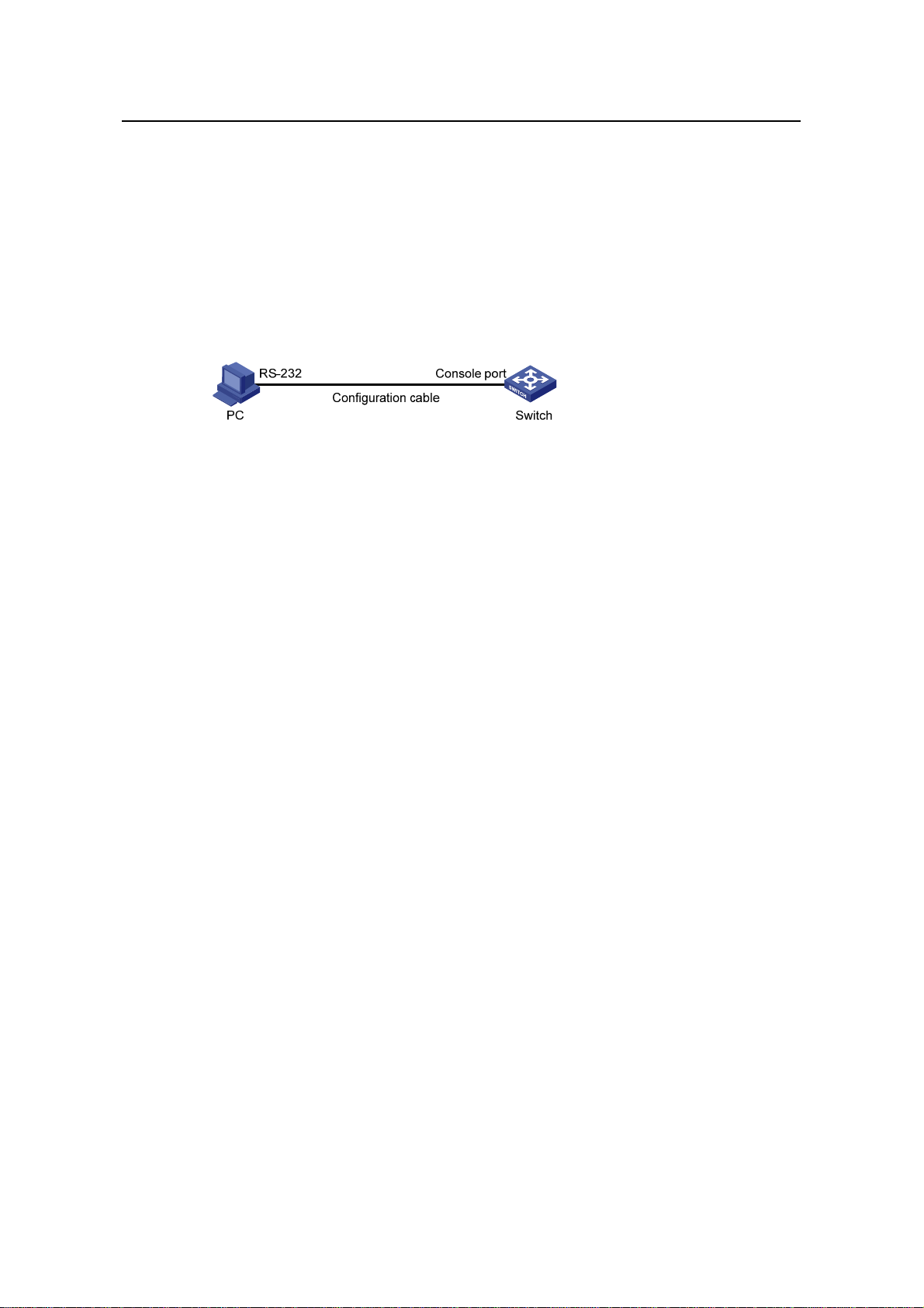
Operation Manual – Login
H3C S3100 Series Ethernet Switches Chapter 3 Logging in through Telnet
z Authenticate users using the local password.
z Set the local password to 123456 (in plain text).
z Commands of level 2 are available to the users.
z Telnet protocol is supported.
z The screen can contain up to 30 lines.
z The history command buffer can contain up to 20 commands.
z The timeout time of VTY 0 is 6 minutes.
II. Network diagram
Figure 3-2 Network diagram for Telnet configuration (with the authentication mode
being password)
III. Configuration procedure
# Enter system view.
<Sysname> system-view
# Enter VTY 0 user interface view.
[Sysname] user-interface vty 0
# Configure to authenticate users logging into VTY 0 using the password.
[Sysname-ui-vty0] authentication-mode password
# Set the local password to 123456 (in plain text).
[Sysname-ui-vty0] set authentication password simple 123456
# Specify commands of level 2 are available to users logging into VTY 0.
[Sysname-ui-vty0] user privilege level 2
# Configure Telnet protocol is supported.
[Sysname-ui-vty0] protocol inbound telnet
# Set the maximum number of lines the screen can contain to 30.
[Sysname-ui-vty0] screen-length 30
# Set the maximum number of commands the history comm and bu ffer can store to 20.
[Sysname-ui-vty0] history-command max-size 20
# Set the timeout time to 6 minutes.
[Sysname-ui-vty0] idle-timeout 6
3-8
Page 66

Operation Manual – Login
H3C S3100 Series Ethernet Switches Chapter 3 Logging in through Telnet
3.4 Telnet Configuration with Authentication Mode Being Scheme
3.4.1 Configuration Procedure
Table 3-6 Telnet configuration with the authentication mode being scheme
Operation Command Description
Enter system view
Enter the
default ISP
domain
view
Configure
the AAA
scheme to
Configure
the
authentic
ation
scheme
be applied
to the
domain
Quit to
system
view
system-view
domain domain-name
scheme { local | none |
radius-scheme
radius-scheme-name
[ local ] |
hwtacacs-scheme
hwtacacs-scheme-nam
e [ local ] }
quit
—
Optional
By default, the local AAA
scheme is applied. If you
specify to apply the local AAA
scheme, you need to perform
the configuration concerning
local user as well.
If you specify to apply an
existing scheme by providing
the radius-scheme-name
argument, you need to
perform the following
configuration as well:
z Perform AAA&RADIUS
z Configure the user name
configuration on the
switch. (Refer to the AAA
part for more.)
and password accordingly
on the AAA server. (Refer
to the user manual of AAA
server.)
Create a local user and
enter local user view
Set the authentication
password for the local
user
Specify the service type
for VTY users
Quit to system view
Enter one or more VTY
user interface views
local-user user-name
password { simple |
cipher } password
service-type telnet
[ level level ]
quit
user-interface vty
first-number
[ last-number ]
3-9
No local user exists by
default.
Required
Required
—
—
Page 67

Operation Manual – Login
H3C S3100 Series Ethernet Switches Chapter 3 Logging in through Telnet
Operation Command Description
Required
The specified AAA scheme
Configure to
authenticate users
locally or remotely
authentication-mode
scheme [ commandauthorization ]
determines whether to
authenticate users locally or
remotely.
Users are authenticated
locally by default.
Configure the command
level available to users
logging into the user
user privilege level
level
interface
Configure the supported
protocol
protocol inbound { all |
ssh | telnet }
Set the commands to be
executed automatically
after a user login to the
user interface
auto-execute
command text
successfully
Make terminal services
available
Set the maximum
number of lines the
screen can contain
shell
screen-length
screen-length
Optional
By default, commands of level
0 are available to users
logging into the VTY user
interfaces.
Optional
Both Telnet protocol and SSH
protocol are supported by
default.
Optional
By default, no command is
executed automatically after a
user logs into the VTY user
interface.
Optional
Terminal services are
available in all use interfaces
by default.
Optional
By default, the screen can
contain up to 24 lines.
You can use the
screen-length 0 command to
disable the function to display
information in pages.
Set history command
buffer size
history-command
max-size value
3-10
Optional
The default history command
buffer size is 10. That is, a
history command buffer can
store up to 10 commands by
default.
Page 68

Operation Manual – Login
H3C S3100 Series Ethernet Switches Chapter 3 Logging in through Telnet
Operation Command Description
Optional
The default timeout time of a
user interface is 10 minutes.
With the timeout time being
10 minutes, the connection to
Set the timeout time for
the user interface
idle-timeout minutes
[ seconds ]
a user interface is terminated
if no operation is performed in
the user interface within 10
minutes.
You can use the idle-timeout
0 command to disable the
timeout function.
Note that if you configure to authenticate the users in the scheme mode, the command
level available to the users logging into the switch depends on the user privilege level
level command and the service-type { ftp | lan-access | { ssh | telnet | terminal }*
[ level level ] } command, as listed in
Table 3-7.
Table 3-7 Determine the command level when users logging into switches are
authenticated in the scheme mode
Scenario
Command
Authenticati
on mode
authenticatio
n-mode
scheme
[ command-a
uthorization ]
User type Command
The user privilege level level
command is not executed, and
the service-type command does
not specify the available
command level.
The user privilege level level
command is not executed, and
VTY users that
are
AAA&RADIUS
the service-type command
specifies the available command
level.
level
Level 0
Determined
by the
service-type
command
authenticated
or locally
authenticated
The user privilege level level
command is executed, and the
service-type command does not
Level 0
specify the available command
level.
The user privilege level level
command is executed, and the
service-type command specifies
the available command level.
Determined
by the
service-type
command
3-11
Page 69

Operation Manual – Login
H3C S3100 Series Ethernet Switches Chapter 3 Logging in through Telnet
Scenario
Command
Authenticati
on mode
User type Command
level
The user privilege level level
command is not executed, and
the service-type command does
not specify the available
command level.
Level 0
The user privilege level level
command is not executed, and
VTY users that
are
authenticated
in the RSA
mode of SSH
the service-type command
specifies the available command
level.
The user privilege level level
command is executed, and the
service-type command does not
specify the available command
level.
The user privilege level level
command is executed, and the
Determined
by the user
privilege
level level
command
service-type command specifies
the available command level.
Note:
The user privilege level level
command is not executed, and
the service-type command does
not specify the available
command level.
The user privilege level level
command is not executed, and
VTY users that
are
authenticated
the service-type command
specifies the available command
level.
in the
password
mode of SSH
The user privilege level level
command is executed, and the
service-type command does not
specify the available command
level.
The user privilege level level
command is executed, and the
service-type command specifies
the available command level.
Level 0
Determined
by the
service-type
command
Level 0
Determined
by the
service-type
command
Refer to AAA Operation and SSH Operation of this manual for information about AAA,
RADIUS, and SSH.
3-12
Page 70

Operation Manual – Login
H3C S3100 Series Ethernet Switches Chapter 3 Logging in through Telnet
3.4.2 Configuration Example
I. Network requirements
Assume current user logins through the Console port and the user level is set to the
administrator level (level 3). Perform the following configurations for users logging into
VTY 0 using Telnet.
z Configure the local user name as “guest”.
z Set the authentication password of the local user to 123456 (in plain text).
z Set the service type of VTY users to Telnet and the command level to 2.
z Configure to authenticate users logging into VTY 0 in scheme mode.
z Only Telnet protocol is supported in VTY 0.
z The screen can contain up to 30 lines.
z The history command buffer can store up to 20 commands.
z The timeout time of VTY 0 is 6 minutes.
II. Network diagram
Figure 3-3 Network diagram for Telnet configuration (with the authentication mode
being scheme)
III. Configuration procedure
# Enter system view.
<Sysname> system-view
# Create a local user named “guest” and enter local user view.
[Sysname] local-user guest
# Set the authentication password of the local user to 123456 (in plain text).
[Sysname-luser-guest] password simple 123456
# Set the service type to Telnet, Specify commands of level 2 are available to users
logging into VTY 0..
[Sysname-luser-guest] service-type telnet level 2
[Sysname-luser-guest] quit
# Enter VTY 0 user interface view.
[Sysname] user-interface vty 0
# Configure to authenticate users logging into VTY 0 in the scheme mode.
[Sysname-ui-vty0] authentication-mode scheme
# Configure Telnet protocol is supported.
3-13
Page 71
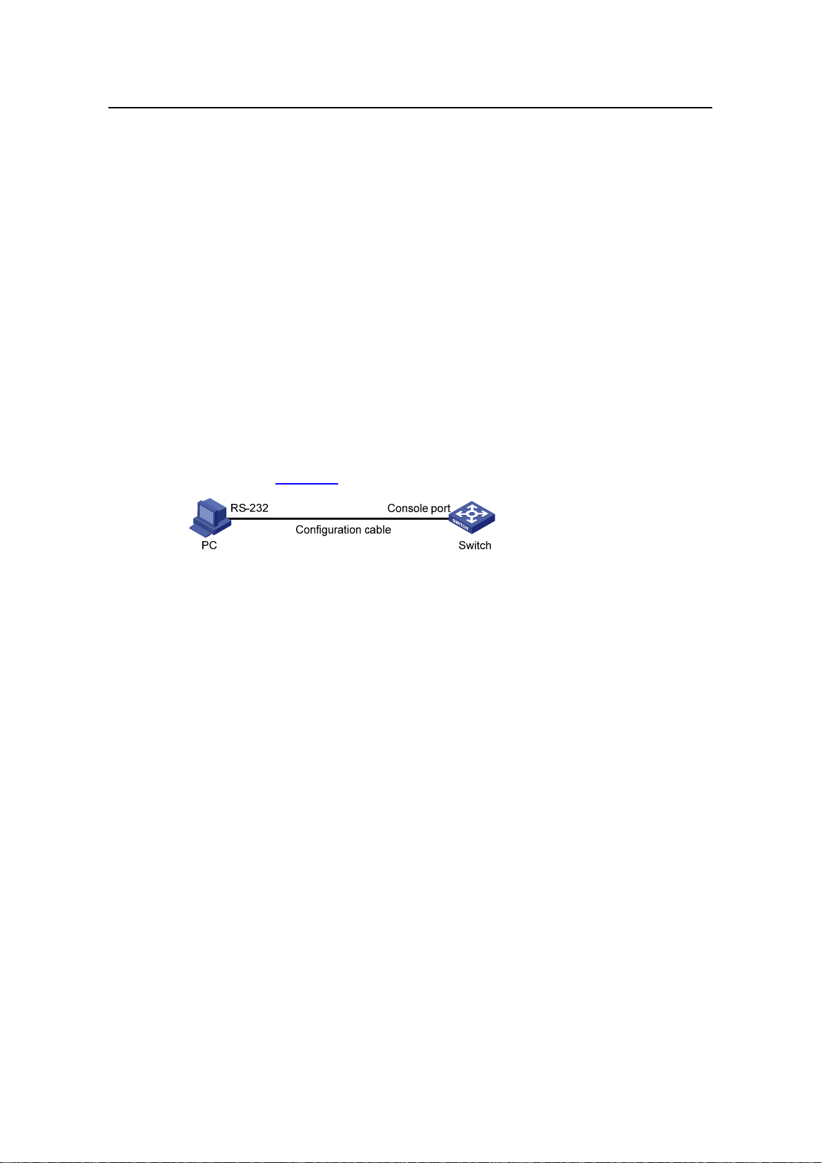
Operation Manual – Login
H3C S3100 Series Ethernet Switches Chapter 3 Logging in through Telnet
[Sysname-ui-vty0] protocol inbound telnet
# Set the maximum number of lines the screen can contain to 30.
[Sysname-ui-vty0] screen-length 30
# Set the maximum number of commands the history comm and bu ffer can store to 20.
[Sysname-ui-vty0] history-command max-size 20
# Set the timeout time to 6 minutes.
[Sysname-ui-vty0] idle-timeout 6
3.5 Telnetting to a Switch
3.5.1 Telnetting to a Switch from a Terminal
1) Assign an IP address to VLAN-interface 1 of the switch (VLAN 1 is the default
VLAN of the switch).
z Connect the serial port of your PC/terminal to the Console port of the switch, as
shown in
Figure 3-4
Figure 3-4 Diagram for establishing connection to a Console port
z Launch a terminal emulation utility (such as Terminal in Windows 3.X or
HyperTerminal in Windows 95/Windows 98/Windows NT/Windows 2000/Windows
XP) on the PC terminal, with the baud rate set to 9,600 bps, data bits set to 8,
parity check set to none, and flow control set to none.
z Turn on the switch and press Enter as prompted. The prompt (such as <H3C>)
appears, as shown in the following figure.
3-14
Page 72

Operation Manual – Login
H3C S3100 Series Ethernet Switches Chapter 3 Logging in through Telnet
Figure 3-5 The terminal window
z Perform the following operations in the terminal window to assign IP address
202.38.160.92/24 to VLAN–interface 1 of the switch.
<Sysname> system-view
[Sysname] interface Vlan-interface 1
[Sysname-Vlan-interface1] ip address 202.38.160.92 255.255.255.0
2) Perform Telnet-related configuration on the switch. Refer to section 3.2 "Telnet
Configuration with Authentication Mode Being None
Configuration with Authentication Mode Being Password
Configuration with Authentication Mode Being Scheme
3) Connect your PC/terminal and the Switch to an Ethernet, as shown in
”, section 3.3 “Telnet
”, and section 3.4 “Telnet
” for more.
Figure 3-6.
Make sure the port through which the switch is connected to the Ethernet belongs
to VLAN 1 and the route between your PC and VLAN-interface 1 is reachable.
Figure 3-6 Network diagram for Telnet connection establishment
3-15
Page 73

Operation Manual – Login
H3C S3100 Series Ethernet Switches Chapter 3 Logging in through Telnet
4) Launch Telnet on your PC, with the IP address of VLAN–interface 1 of the switch
as the parameter, as shown in
Figure 3-7.
Figure 3-7 Launch Telnet
5) If the password authentication mode is specified, enter the password when the
Telnet window displays “Login authentication” and prompts for login password.
The CLI prompt (such as <Sysname>) appears if the password is correct. If all
VTY user interfaces of the switch are in use, you will fail to establish the
connection and receive the message that says “All user interfaces are used,
please try later!”. A H3C series Ethernet switch can accommodate up to five Telnet
connections at same time.
6) After successfully Telnetting to the switch, you can configure the switch or display
the information about the switch by executing corresponding commands. You can
also type ? at any time for help. Refer to the relevant parts in this manual for the
information about the commands.
Note:
z A Telnet connection is terminated if you delete or modify the IP address of the VLAN
interface in the Telnet session.
z By default, commands of level 0 are available to Telnet users authenticated by
password. Refer to section 1.2 “Command Hierarchy/Command View” in CLI part
for information about command hierarchy.
3.5.2 Telnetting to another Switch from the Current Switch
Y ou can Telnet to another switch from the current switch. In this case, the current switch
operates as the client, and the other operates as the server. If the interconnected
Ethernet ports of the two switches are in the same LAN segment, make sure the IP
addresses of the two management VLAN interfaces to which the two Ethernet ports
belong to are of the same network segment, or the route between the two VLAN
interfaces is available.
3-16
Page 74

Operation Manual – Login
H3C S3100 Series Ethernet Switches Chapter 3 Logging in through Telnet
As shown in Figure 3-8, after Telnetting to a switch (labeled as Telnet client), you can
Telnet to another switch (labeled as Telnet server) by executing the telnet command
and then configure it.
Figure 3-8 Network diagram for Telnetting to another switch from the current switch
1) Perform Telnet-related configuration on the switch operating as the Telnet server.
Refer to section
section
section
3.3 “Telnet Configuration with Authentication Mode Being Password”, and
3.4 “Telnet Configuration with Authentication Mode Being Scheme” for
3.2 "Telnet Configuration with Authentication Mode Being None”,
more.
2) Telnet to the switch operating as the Telnet client.
3) Execute the following command on the switch operating as the Telnet client:
<Sysname> telnet xxxx
Note that xxxx is the IP address or the host name of the switch operating as the Telnet
server. You can use the ip host to assign a host name to a switch.
4) After successful login, the CLI prompt (such as <Sysname>) appears. If all the
VTY user interfaces of the switch are in use, you will fail to establish the
connection and receive the message that says “All user interfaces are used,
please try later!”.
5) After successfully Telnetting to the switch, you can configure the switch or display
the information about the switch by executing corresponding commands. You can
also type ? at any time for help. Refer to the following chapters for the information
about the commands.
3-17
Page 75

Operation Manual – Login
H3C S3100 Series Ethernet Switches Chapter 4 Logging in Using a Modem
Chapter 4 Logging in Using a Modem
4.1 Introduction
The administrator can log into the Console port of a remote switch using a modem
through public switched telephone network (PSTN) if the remote switch is connected to
the PSTN through a modem to configure and maintain the switch remotely. When a
network operates improperly or is inaccessible, you can manage switches in the
network remotely in this way.
To log into a switch in this way, you need to configure the administrator side and the
switch properly, as listed in the following table.
Table 4-1 Requirements for logging into a switch using a modem
Item Requirement
The PC can communicate with the modem connected to it.
Administrator
side
Switch side
The modem is properly connected to PSTN.
The telephone number of the switch side is available.
The modem is connected to the Console port of the switch properly.
The modem is properly configured.
The modem is properly connected to PSTN and a telephone set.
The authentication mode and other related settings are configured
on the switch. Refer to
Table 2-3.
4.2 Configuration on the Switch Side
4.2.1 Modem Configuration
Perform the following configuration on the modem directly connected to the switch:
AT&F ----------------------- Restore the factory settings
ATS0=1 ----------------------- Configure to answer automatically after the
first ring
AT&D ----------------------- Ignore DTR signal
AT&K0 ----------------------- Disable flow control
AT&R1 ----------------------- Ignore RTS signal
AT&S0 ----------------------- Set DSR to high level by force
ATEQ1&W ----------------------- Disable the Modem from returning command
response and the result, save the changes
4-1
Page 76

Operation Manual – Login
H3C S3100 Series Ethernet Switches Chapter 4 Logging in Using a Modem
You can verify your configuration by executing the AT&V command.
Note:
The configuration commands and the output of different modems may differ. Refer to
the user manual of the modem when performing the above configuration.
4.2.2 Switch Configuration
Note:
After logging into a switch through its Console port by using a m odem, you will enter the
AUX user interface. The corresponding configuration on the switch is the same as
those when logging into the switch locally through its Console port except that:
z When you log in through the Console port using a modem, the baud rate of the
Console port is usually set to a value lower than the transmission speed of the
modem. Otherwise, packets may get lost.
z Other settings of the Console port, such as the check mode, the stop bits, and the
data bits, remain the default.
The configuration on the switch depends on the authentication mode the user is in.
Refer to
Table 2-3 for the information about authentication mode configuration.
I. Configuration on switch when the authentication mode is none
Refer to section 2.4 “Console Port Login Configuration with Authentication Mode Being
”.
None
II. Configuration on switch when the authentication mode is password
Refer to section 2.5 “Console Port Login Configuration with Authentication Mode Being
Password
”.
III. Configuration on switch when the authentication mode is scheme
Refer to section 2.6 “Console Port Login Configuration with Authentication Mode Being
Scheme
”.
4.3 Modem Connection Establishment
1) Before using Modem to log in the switch, perform corresponding configuration for
different authentication modes on the switch. Refer to section
2.4 "Console Port
4-2
Page 77

Operation Manual – Login
H3C S3100 Series Ethernet Switches Chapter 4 Logging in Using a Modem
Login Configuration with Authentication Mode Being None”, section 2.5 “Console
Port Login Configuration with Authentication Mode Being Password
”, and section
2.6 “Console Port Login Configuration with Authentication Mode Being Scheme”
for more.
2) Perform the following configuration to the modem directly connected to the switch.
Refer to section
3) Connect your PC, the modems, and the switch, as shown in
4.2.1 “Modem Configuration” for related configuration.
Figure 4-1. Make sure
the modems are properly connected to telephone lines.
Modem serial cable
Telephone line
PSTN
Modem
Telephone number
of the romote end:
82882285
Console port
Modem
Figure 4-1 Establish the connection by using modems
4) Launch a terminal emulation utility on the PC and set the telephone number to call
the modem directly connected to the switch, as shown in
Figure 4-2 through
Figure 4-4. Note that you need to set the telephone number to that of the modem
directly connected to the switch.
Figure 4-2 Create a connection
4-3
Page 78

Operation Manual – Login
H3C S3100 Series Ethernet Switches Chapter 4 Logging in Using a Modem
Figure 4-3 Set the telephone number
Figure 4-4 Call the modem
5) If the password authentication mode is specified, enter the password when
prompted. If the password is correct, the prompt (such as <Sysname>) appears.
You can then configure or manage the switch. You can also enter the character ?
at anytime for help. Refer to the related parts in this manual for information about
the configuration commands.
Note:
If you perform no AUX user-related configuration on the switch, the command s of level
3 are available to modem users. Refer to the CLI part for information about command
level.
4-4
Page 79

Operation Manual – Login
H3C S3100 Series Ethernet Switches
Chapter 5 Logging in through the Web-based
Network Management System
Chapter 5 Logging in through the Web-based
Network Management System
5.1 Introduction
An S3100 Ethernet switch has a Web server built in. It enables yo u to log into an S3100
Ethernet switch through a Web browser and then manage and maintain the switch
intuitively by interacting with the built-in Web server.
To log into an S3100 Ethernet switch through the built-in Web-based network
management system, you need to perform the related configuration on both the switch
and the PC operating as the network management terminal.
Table 5-1 Requirements for logging into a switch through the Web-based netwo rk
management system
Item Requirement
The VLAN interface of the switch is assigned an IP
address, and the route between the switch and the Web
network management terminal is reachable. (Refer to the
Switch
PC operating as the
network management
terminal
IP Address Configuration – IP Performance Configuration
and Routing Protocol parts for related information.)
The user name and password for logging into the
Web-based network management system are configured.
IE is available.
The IP address of the VLAN interface of the switch, the
user name, and the password are available.
5.2 Establishing an HTTP Connection
1) Assign an IP address to VLAN-interface 1 of the switch (VLAN 1 is the default
VLAN of the switch). See section
related information.
2) Configure the user name and the password on the switch for the Web network
management user to log in.
3.5.1 "Telnetting to a Switch from a Terminal" for
# Create a Web user account, setting both the user name and the password to “admin ”
and the user level to 3.
<Sysname> system-view
[Sysname] local-user admin
[Sysname-luser-admin] service-type telnet level 3
5-1
Page 80
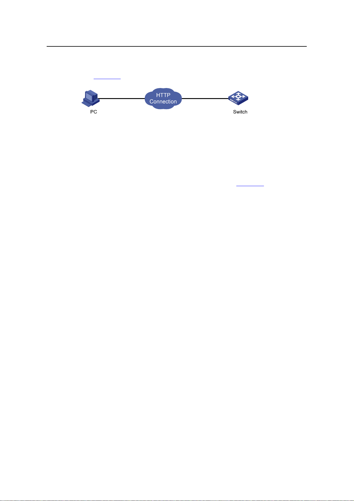
Operation Manual – Login
H3C S3100 Series Ethernet Switches
[Sysname-luser-admin] password simple admin
3) Establish an HTTP connection between your PC and the switch, as shown in
Figure 5-1.
Figure 5-1 Establish an HTTP connection between your PC and the switch
4) Log into the switch through IE. Launch IE on the Web-based network
management terminal (your PC) and enter the IP address of the management
VLAN interface of the switch in the address bar. (Make sure the route between the
Web-based network management terminal and the switch is available.)
5) When the login authentication interface (as shown in
the user name and the password configured in step 2 and click <Login> to bring up
the main page of the Web-based network management system.
Chapter 5 Logging in through the Web-based
Network Management System
Figure 5-2) appears, enter
Figure 5-2 The login page of the Web-based network management system
5.3 Configuring the Login Banner
5.3.1 Configuration Procedure
If a login banner is configured with the header command, when a user logs in through
Web, the banner page is displayed before the user login authentication page. The
contents of the banner page are the login banner information configured with the
header command. Then, by clicking <Continue> on the banner page, the user can
enter the user login authentication page, and enter the main page of the Web-based
network management system after passing the authentication. If no login banner is
configured by the header command, a user logging in through Web directly enters the
user login authentication page.
5-2
Page 81

Operation Manual – Login
H3C S3100 Series Ethernet Switches
Table 5-2 Configure the login banner
Operation Command Description
Chapter 5 Logging in through the Web-based
Network Management System
Enter system view
Configure the banner to be
displayed when a user logs
in through Web
5.3.2 Configuration Example
I. Network requirements
z A user logs in to the switch through Web.
z The banner page is desired when a user logs into the switch.
II. Network diagram
Figure 5-3 Network diagram for login banner configuration
system-view
header login text
—
Required
By default, no login banner
is configured.
III. Configuration Procedure
# Enter system view.
<Sysname> system-view
# Configure the banner "Welcome" to be displayed when a user logs into the switch
through Web.
[Sysname] header login %Welcome%
Assume that a route is available between the user terminal (the PC) and the switch.
After the above-mentioned configuration, if you enter the IP address of the switch in the
address bar of the browser running on the user terminal and press <Enter>, the
browser will display the banner page, as shown in
Figure 5-4.
5-3
Page 82
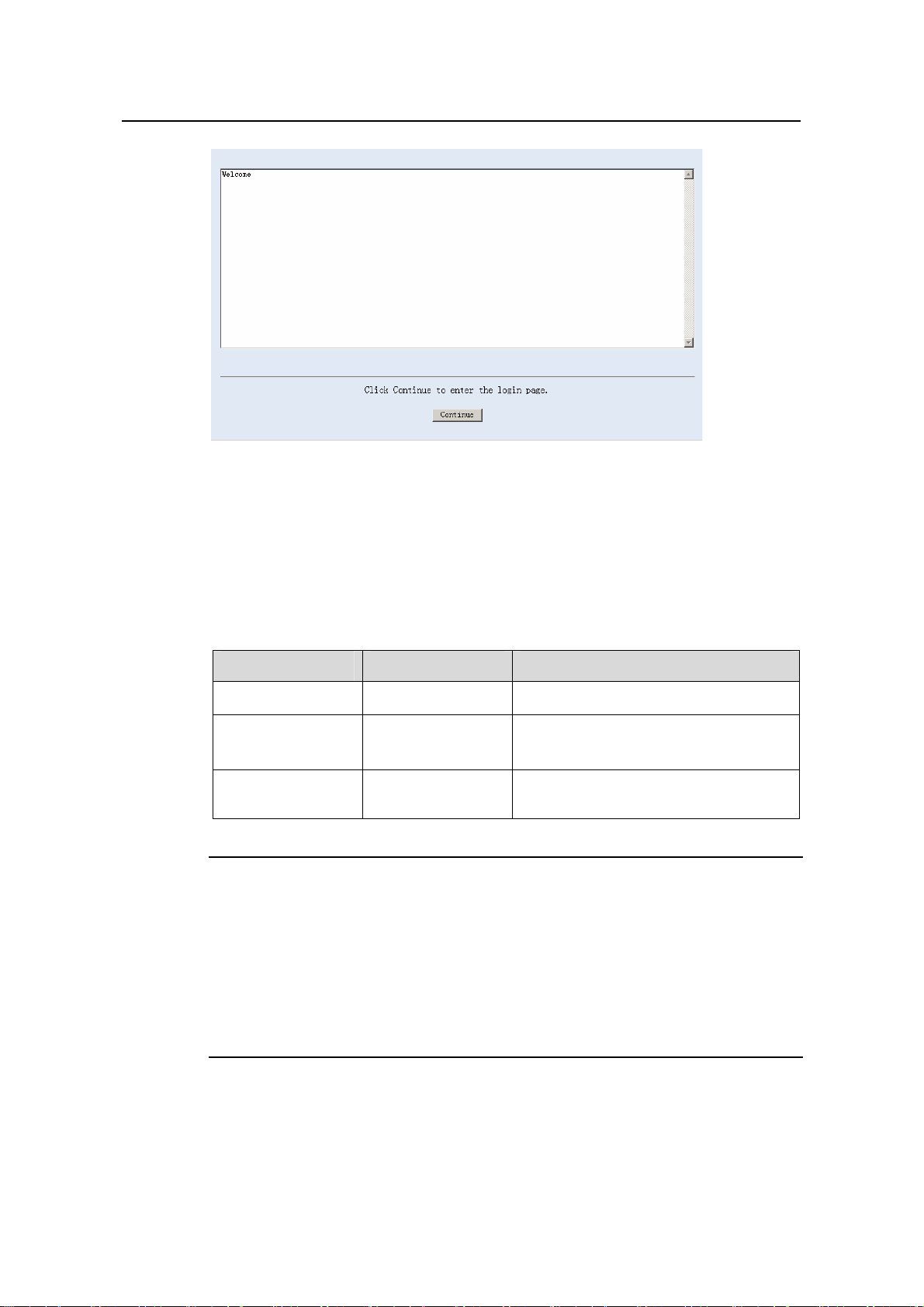
Operation Manual – Login
H3C S3100 Series Ethernet Switches
Figure 5-4 Banner page displayed when a user logs in to the switch through Web
Click <Continue> to enter user login authentication page. You will enter the main page
of the Web-based network management system if the authentication succeeds.
Chapter 5 Logging in through the Web-based
Network Management System
5.4 Enabling/Disabling the WEB Server
Table 5-3 Enable/Disable the WEB Server
Operation Command Description
Enter system view
Enable the Web
server
Disable the Web
server
Note:
To improve security and prevent attack to the unused Sockets, TCP 80 port (which is
for HTTP service) is enabled/disabled after the corresponding configuration.
z Enabling the Web server (by using the undo ip http shutdown command) opens
TCP 80 port.
z Disabling the Web server (by using the ip http shutdown command) closes TCP
80 port.
system-view
ip http shutdown
undo ip http
shutdown
—
Required
By default, the Web server is enabled.
Required
5-4
Page 83
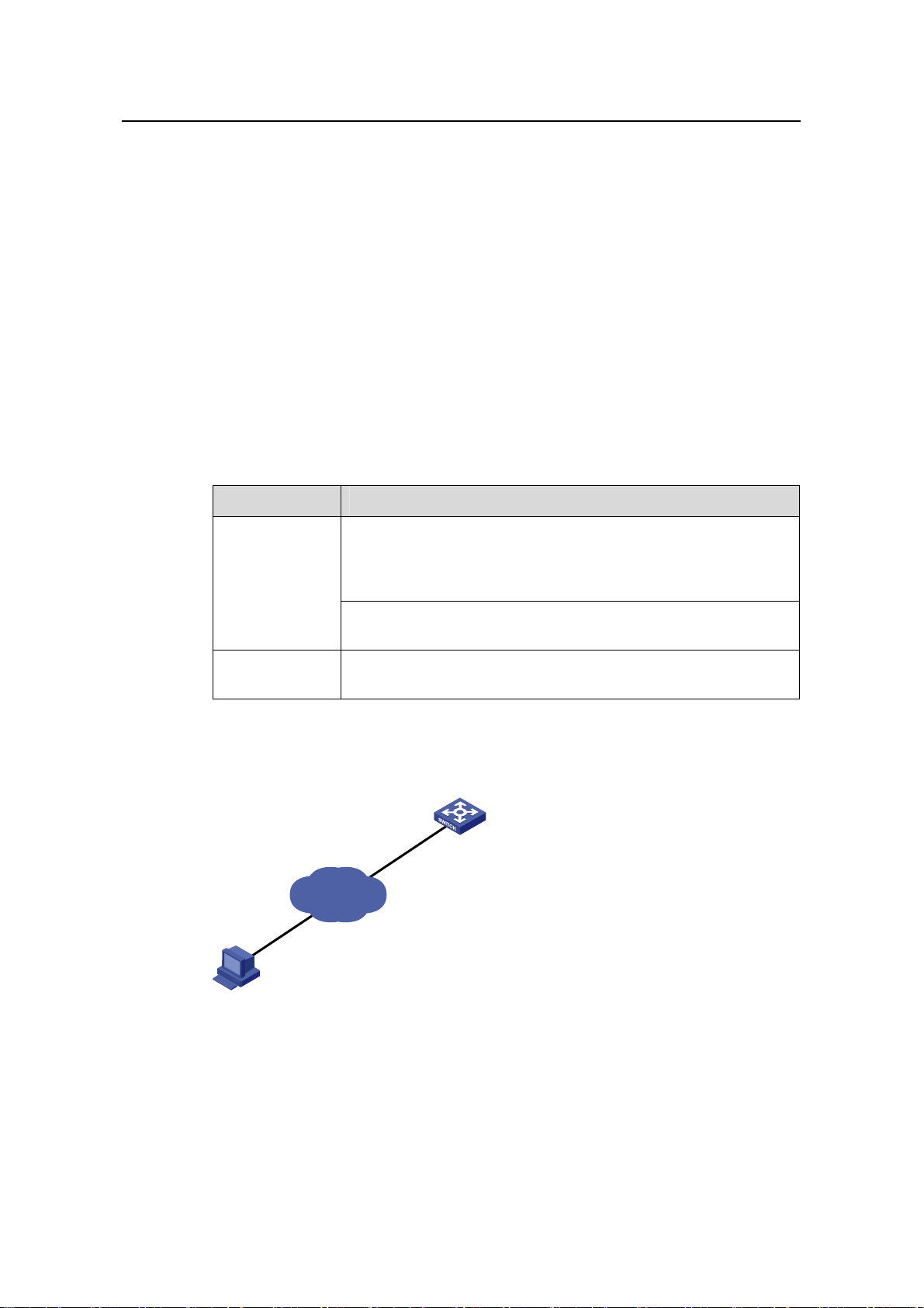
Operation Manual – Login
H3C S3100 Series Ethernet Switches Chapter 6 Logging in through NMS
Chapter 6 Logging in through NMS
6.1 Introduction
You can also log into a switch through a network management station (NMS), and then
configure and manage the switch through the agent module on the switch. Simple
network management protocol (SNMP) is applied between the NMS and the agent.
Refer to the SNMP-RMON part for related information.
To log into a switch through an NMS, you need to perform related configuration on both
the NMS and the switch.
Table 6-1 Requirements for logging into a switch through an NMS
Item Requirement
The IP address of the VLAN interface of the switch i s configured.
The route between the NMS and the switch is reachable. (Refer
Switch
to the IP Address Configuration – IP Performance Configuration
and Routing Protocol parts for related information.)
The basic SNMP functions are configured. (Refer to the
SNMP-RMON part for related information.)
NMS
The NMS is properly configured. (Refer to the user manual of
your NMS for related information.)
6.2 Connection Establishment Using NMS
Switch
Network
NMS
Figure 6-1 Network diagram for logging in through an NMS
6-1
Page 84

Operation Manual – Login
H3C S3100 Series Ethernet Switches Chapter 7 User Control
Chapter 7 User Control
Note:
Refer to the ACL part for information about ACL.
7.1 Introduction
A switch provides ways to control different types of login users, as listed in Table 7-1.
Table 7-1 Ways to control different types of login users
Login
mode
Telnet
SNMP
WEB
Control
method
By source IP
address
By source and
destination IP
address
By source
MAC address
By source IP
addresses
By source IP
addresses
Disconnect
Web users by
force
Implementation Related section
Through basic
ACL
Through
advanced ACL
Through Layer 2
ACL
Through basic
ACL
Through basic
ACL
By executing
commands in
CLI
Section 7.2.2 “”Controlling Telnet
Users by Source IP Addresses
Section 7.2.3 “Controlling Telnet
Users by Source and Destination
IP Addresses
Section
Users by Source MAC
Addresses
Section
Management Users by Source IP
Addresses
Section 7.4 Controlling Web
Users by Source IP Address
Section
Web User by Force
”.
7.2.4 “Controlling Telnet
”
7.3 “Controlling Network
”.
7.4.3 Disconnecting a
.
7.2 Controlling Telnet Users
7.2.1 Prerequisites
The controlling policy against Telnet users is determined, including the source IP
addresses, destination IP addresses and source MAC addresses to be controlled and
the controlling actions (permitting or denying).
7-1
Page 85
Operation Manual – Login
H3C S3100 Series Ethernet Switches Chapter 7 User Control
7.2.2 Controlling Telnet Users by Source IP Addresses
Controlling Telnet users by source IP addresses is achieved by applying basic ACLs,
which are numbered from 2000 to 2999.
Table 7-2 Control Telnet users by source IP addresses
Operation Command Description
Enter system view
Create a basic ACL
or enter basic ACL
view
Define rules for the
ACL
Quit to system view
Enter user
interface view
Apply the ACL to
control Telnet
users by source IP
addresses
system-view
acl number acl-number
[ match-order { config |
auto } ]
rule [ rule-id ] { deny |
permit } [ rule-string ]
quit
user-interface [ type ]
first-number [ last-number ]
acl acl-number { inbound |
outbound }
—
As for the acl number
command, the config
keyword is specified by
default.
Required
—
—
Required
The inbound keyword
specifies to filter the users
trying to Telnet to the current
switch.
The outbound keyword
specifies to filter users trying
to Telnet to other switches
from the current switch.
7.2.3 Controlling Telnet Users by Source and Destination IP Addresses
Controlling Telnet users by source and destination IP addresses is achieved by
applying advanced ACLs, which are numbered from 3000 to 3999.
Table 7-3 Control Telnet users by source and destination IP addresses
Operation Command Description
Enter system view
Create an
advanced ACL or
enter advanced
ACL view
Define rules for the
ACL
system-view
acl number acl-number
[ match-order { config |
auto } ]
rule [ rule-id ] { deny |
permit } protocol
[ rule-string ]
7-2
—
As for the acl number command,
the config keyword is specified by
default.
Required
You can define rules as needed to
filter by specific source and
destination IP addresses.
Page 86

Operation Manual – Login
H3C S3100 Series Ethernet Switches Chapter 7 User Control
Operation Command Description
Quit to system view
Enter user
interface view
quit
user-interface [ type ]
first-number
[ last-number ]
—
—
Required
Apply the ACL to
control Telnet
users by specified
source and
destination IP
addresses
acl acl-number
{ inbound | outbound }
The inbound keyword specifies to
filter the users trying to Telnet to
the current switch.
The outbound keyword specifies
to filter users trying to Telnet to
other switches from the current
switch.
7.2.4 Controlling Telnet Users by Source MAC Addresses
Controlling Telnet users by source MAC addresses is achieved by applying Layer 2
ACLs, which are numbered from 4000 to 4999.
Table 7-4 Control Telnet users by source MAC addresses
Operation Command Description
Enter system view
Create or enter
Layer 2 ACL view
system-view
acl number acl-number
—
—
Required
Define rules for the
ACL
rule [ rule-id ] { deny |
permit } [ rule-string ]
You can define rules as
needed to filter by specific
source MAC addresses.
Quit to system view
Enter user
interface view
quit
user-interface [ type ]
first-number [ last-number ]
—
—
Apply the ACL to
control Telnet
users by specified
source MAC
acl acl-number inbound
Required
By default, no ACL is applied
for Telnet users.
addresses
7-3
Page 87
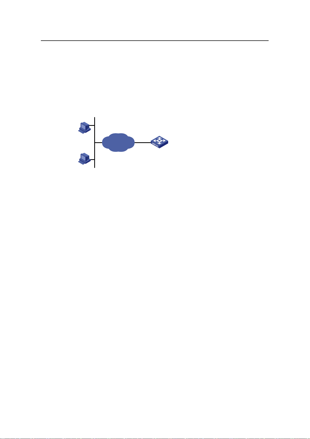
Operation Manual – Login
H3C S3100 Series Ethernet Switches Chapter 7 User Control
7.2.5 Configuration Example
I. Network requirements
Only the Telnet users sourced from the IP address of 10.110.100.52 are permitted to
access the switch.
II. Network diagram
10.110.100.46
Host A
IP network
Switch
Host B
10.110.100.52
Figure 7-1 Network diagram for controlling Telnet users using ACLs
III. Configuration procedure
# Define a basic ACL.
<Sysname> system-view
[Sysname] acl number 2000
[Sysname-acl-basic-2000] rule 1 permit source 10.110.100.52 0
[Sysname-acl-basic-2000] quit
# Apply the ACL.
[Sysname] user-interface vty 0 4
[Sysname-ui-vty0-4] acl 2000 inbound
7.3 Controlling Network Management Users by Source IP Addresses
You can manage an S3100 Ethernet switch through network management software.
Network management users can access switches through SNMP.
Y ou need to perform the following two operatio ns to control network management users
by source IP addresses.
z Defining an ACL
z Applying the ACL to control users accessing the switch through SNMP
7-4
Page 88
Operation Manual – Login
H3C S3100 Series Ethernet Switches Chapter 7 User Control
7.3.1 Prerequisites
The controlling policy against network management users is determined, including the
source IP addresses to be controlled a nd the controlling actions (permitting or denying).
7.3.2 Controlling Network Management Users by Source IP Addresses
Controlling network management users by source IP addresses is achieved by
applying basic ACLs, which are numbered from 2000 to 2999.
Follow these steps to control network management users by source IP addresses:
To do… Use the command… Remarks
Enter system view
Create a basic ACL
or enter basic ACL
view
Define rules for the
ACL
Quit to system view
Apply the ACL while
configuring the
SNMP community
name
Apply the ACL while
configuring the
SNMP group name
Apply the ACL while
configuring the
SNMP user name
system-view
acl number acl-number
[ match-order { auto | config } ]
rule [ rule-id ] { deny | permit }
[ rule-string ]
quit
snmp-agent community { read |
write } community-name [ acl
acl-number | mib-view view-name ]*
snmp-agent group { v1 | v2c }
group-name [ read-view read-view ]
[ write-view write-view ]
[ notify-view notify-view ] [ acl
acl-number ]
snmp-agent group v3 group-name
[ authentication | privacy ]
[ read-view read-view ] [ write-view
write-view ] [ notify-view
notify-view ] [ acl acl-number ]
snmp-agent usm-user { v1 | v2c }
user-name group-name [ acl
acl-number ]
snmp-agent usm-user v3
user-name group-name [ [ cipher ]
authentication-mode { md5 | sha }
auth-password [ privacy-mode
{ des56 | aes128 } priv-password ] ]
[ acl acl-number ]
—
As for the acl
number command,
the config keyword
is specified by
default.
Required
—
Required
According to the
SNMP version and
configuration
customs of NMS
users, you can
reference an ACL
when configuring
community name,
group name or
username. For the
detailed
configuration, refer to
SNMP-RMON for
more.
7-5
Page 89

Operation Manual – Login
H3C S3100 Series Ethernet Switches Chapter 7 User Control
7.3.3 Configuration Example
I. Network requirements
Only SNMP users sourced from the IP addresses of 10.110.100.52 are permitted to log
into the switch.
II. Network diagram
10.110.100.46
Host A
IP network
Switch
Host B
10.110.100.52
Figure 7-2 Network diagram for controlling SNMP users using ACLs
III. Configuration procedure
# Define a basic ACL.
<Sysname> system-view
[Sysname] acl number 2000
[Sysname-acl-basic-2000] rule 1 permit source 10.110.100.52 0
[Sysname-acl-basic-2000] quit
# Apply the ACL to only permit SNMP users sourced from the IP addresses of
10.110.100.52 to access the switch.
[Sysname] snmp-agent community read aaa acl 2000
[Sysname] snmp-agent group v2c groupa acl 2000
[Sysname] snmp-agent usm-user v2c usera groupa acl 2000
7.4 Controlling Web Users by Source IP Address
You can manage an S3100 Ethernet switch remotely through Web. Web users can
access a switch through HTTP connections.
You need to perform the following two operations to control Web users by source IP
addresses.
z Defining an ACL
z Applying the ACL to control Web users
7-6
Page 90

Operation Manual – Login
H3C S3100 Series Ethernet Switches Chapter 7 User Control
7.4.1 Prerequisites
The controlling policy against Web users is determined, including the source IP
addresses to be controlled and the controlling actions (permitting or denying).
7.4.2 Controlling Web Users by Source IP Addresses
Controlling Web users by source IP addresses is achieved by applying basic ACLs,
which are numbered from 2000 to 2999.
Table 7-5 Control Web users by source IP addresses
Operation Command Description
Enter system view
Create a basic ACL
or enter basic ACL
view
Define rules for the
ACL
Quit to system view
Apply the ACL to
control Web users
system-view
acl number acl-number
[ match-order { config |
auto } ]
rule [ rule-id ] { deny |
permit } [ rule-string ]
quit
ip http acl acl-number
7.4.3 Disconnecting a Web User by Force
The administrator can disconnect a Web user by force using the related commands.
Table 7-6 Disconnect a Web user by force
Operation Command Description
—
As for the acl number
command, the config
keyword is specified by
default.
Required
—
Optional
By default, no ACL is applied
for Web users.
Disconnect a Web
user by force
free web-users { all |
user-id user-id | user-name
user-name }
7.4.4 Configuration Example
I. Network requirements
Only the Web users sourced from the IP address of 10.110.100.52 are permitted to
access the switch.
Required
Execute this command in user
view.
7-7
Page 91

Operation Manual – Login
H3C S3100 Series Ethernet Switches Chapter 7 User Control
II. Network diagram
10.110.100.46
Host A
IP network
Switch
Host B
10.110.100.52
Figure 7-3 Network diagram for controlling Web users using ACLs
III. Configuration procedure
# Define a basic ACL.
<Sysname> system-view
[Sysname] acl number 2030
[Sysname-acl-basic-2030] rule 1 permit source 10.110.100.52 0
[Sysname-acl-basic-2030] quit
# Apply ACL 2030 to only permit the Web users sourced from the IP address of
10.110.100.52 to access the switch.
[Sysname] ip http acl 2030
7-8
Page 92

Operation Manual – Configuration File Management
H3C S3100 Series Ethernet Switches Table of Contents
Table of Contents
Chapter 1 Configuration File Management................................................................................. 1-1
1.1 Introduction to Configuration File....................................................................................... 1-1
1.2 Management of Configuration File.....................................................................................1-2
1.2.1 Saving the Current Configuration............................................................................ 1-2
1.2.2 Erasing the Startup Configuration File....................................................................1-4
1.2.3 Specifying a Configuration File for Next Startup..................................................... 1-4
1.2.4 Displaying Device Configuration.............................................................................1-5
i
Page 93

Operation Manual – Configuration File Management
H3C S3100 Series Ethernet Switches Chapter 1 Configuration File Management
Chapter 1 Configuration File Management
1.1 Introduction to Configuration File
A configuratio n file records and stores user configurations performed to a switch. It also
enables users to check switch configurations easily.
I. Types of configuration
The configuration of a device falls into two types:
z Saved configuration, a configuration file used for initialization. If this file does not
exist, the device starts up without loading any configuration file.
z Current configuration, which refers to the user’s configuration du ring the operation
of a device. This configuration is stored in dynamic random-access memory
(DRAM). It is removed when rebooting.
II. Format of configuration file
Configuration files are saved as text files for ease of reading. They:
z Save configuration in the form of commands.
z Save only non-default configuration settings.
z The commands are grouped into sections by command view. The commands tha t
are of the same command view are grouped into one section. Sections are
separated by comment lines. (A line is a comment line if it starts with the character
“#”.)
z The sections are listed in this order: system configuration section, logical interface
configuration section, physical port configuration section, routing protocol
configuration section, user interface configuration, and so on.
z End with a return.
The operating interface provided by the configuration file management function is
user-friendly. With it, you can easily manage your configuration files.
III. Main/backup attribute of the configuration file
Main and backup indicate the main and backup attribute of the configuration file
respectively . A main configuratio n file and a backup configuration file can coexist on the
device. As such, when the main configuration file is missing or damaged, the backup
file can be used instead. This increases the safety and reliability of the file system
compared with the device that only support one configuration file. You can configure a
file to have both main and backup attribute, but only one file of either main or backup
attribute is allowed on a device.
The following three situations are concerned with the main/backup attributes:
1-1
Page 94

Operation Manual – Configuration File Management
H3C S3100 Series Ethernet Switches Chapter 1 Configuration File Management
z When saving the current configuration, you can specify the file to be a main or
backup or normal configuration file.
z When removing a configuration file from a device, you can specify to remove the
main or backup configuration file. Or, if it is a file having both main and backup
attribute, you can specify to erase the main or backup attribute of the file.
z When setting the configuration file for next startup, you can specify to use the main
or backup configuration file.
IV. Startup with the configuration file
When booting, the system chooses the configuration files following the rules below:
1) If the main configuration file exists, the device initializes with this configuration.
2) If the main configuration file does not exist but the backup configuration file exists,
the device initializes with the backup configuration.
3) If neither the main nor the backup configuration file exists:
z For an S3100-SI Ethernet switch, the switch starts up without loading the
configuration file;
z For an S3100-EI Ethernet switch, if the default configuration file config.def exists,
the switch initializes with the default configuration file; if the default configuration
file does not exist, the switch starts up without loading the configuration file.
1.2 Management of Configuration File
Table 1-1 Complete these tasks to configure configuration file management
Task Remarks
Saving the Current Configuration Optional
Erasing the Startup Configuration File Optional
Specifying a Configuration File for Next Startup Optional
1.2.1 Saving the Current Configuration
Y ou can modify the configuration on your device at the comm and line interface (CLI). To
use the modified configuration for your subsequent startup s, you must save it (using the
save command) as a configuration file.
Table 1-2 Save current configuration
Operation Command Description
Save current
configuration
save [ cfgfile | [ safely ]
[ backup | main ] ]
Required
Available in any view
1-2
Page 95

Operation Manual – Configuration File Management
H3C S3100 Series Ethernet Switches Chapter 1 Configuration File Management
I. Modes in saving the configuration
z Fast saving mode. This is the mode when you use the save command without the
safely keyword. The mode saves the file quicker but is likely to lose the original
configuration file if the device reboots or the power fails during the process.
z Safe mode. This is the mode when you use the save command with the safely
keyword. The mode saves the file slower but can retain the original configuration
file in the device even if the device reboots or the power fails during the process.
Caution:
S3100 series Ethernet switches do not support the safe mode. When you are sav ing a
configuration file using the save safely command, if the device reboots or the power
fails during the saving process, the configuration file will be lost.
II. Three attributes of the configuration file
z Main attribute. When you use the save [ [ safely ] [ main ] ] command to save the
current configuration, the configuration file you get has main attribute. If this
configuration file already exists and has backup attribute, the file will have both
main and backup attributes after execution of this command. If the filename you
entered is different from that existing in the system, this command will erase its
main attribute to allow only one main attribute configuration file in the device.
z Backup attribute. When you use the save [ safely ] backup command to save the
current configuration, the configuration file you get has backup attribute. If this
configuration file already exists and has main attribute, the file will have both main
and backup attributes after execution of this command. If the filename you entered
is different from that existing in the system, this command will erase its backup
attribute to allow only one backup attribute configuration file in the device.
z Normal attribute. When you use the save cfgfile command to save the current
configuration, the configuration file you get has normal attribute if it is not an
existing file. Otherwise, the attribute is dependent on the original attribute of the
file.
Note:
The extension name of the configuration file must be .cfg.
1-3
Page 96
Operation Manual – Configuration File Management
H3C S3100 Series Ethernet Switches Chapter 1 Configuration File Management
1.2.2 Erasing the Startup Configuration File
Y ou can cl ear the configuration files save d on the device through commands. After you
clear the configuration files, the device starts up without loading the configuration file
the next time it is started up.
Table 1-3 Erase the configuration file
Operation Command Description
Erase the startup
configuration file from the
storage device
reset
saved-configuration
[ backup | main ]
Required
Available in user view
You may need to erase the configuration file for one of these reasons:
z After you upgrade software, the old configuration file does not match the new
software.
z The startup configuration file is corrupted or not the one you needed.
The following two situations exist:
z While the reset saved-configuration [ main ] command erases the configuration
file with main attribute, it only erases the main attribute of a configuration file
having both main and backup attribute.
z While the reset saved-configuration backup command erases the configuration
file with backup attribute, it only erases the backup attribute of a configuration file
having both main and backup attribute.
Caution:
This command will permanently delete the configuration file from the device.
1.2.3 Specifying a Configuration File for Next Startup
Table 1-4 Specify a configuration file for next startup
Operation Command Description
Specify a configuration file
for next startup
You can specify a configuration file to be used for the next startup and configure the
main/backup attribute for the configuration file.
startup
saved-configuration
cfgfile [ backup | main ]
1-4
Required
Available in user view
Page 97

Operation Manual – Configuration File Management
H3C S3100 Series Ethernet Switches Chapter 1 Configuration File Management
I. Assign main attribute to the startup configuration file
z If you save the current configuration to the main configuration file, the system will
automatically set the file as the main startup configuration file.
z You can also use the startup saved-configuration cfgfile [ main ] command to
set the file as main startup configuration file.
II. Assign backup attribute to the startup configuration file
z If you save the current configuration to the backup configuration file, the system
will automatically set the file as the backup startup configuration file.
z You can also use the startup saved-configuration cfgfile backup command to
set the file as backup startup configuration file.
Caution:
The configuration file must use “.cfg” as its extension name and the startup
configuration file must be saved at the root directory of the device.
1.2.4 Displaying Device Configuration
After the above configuration, you can execute the display command in any view to
display the current and initial configurations of the device, so as to verify your
configuration.
1-5
Page 98

Operation Manual – Configuration File Management
H3C S3100 Series Ethernet Switches Chapter 1 Configuration File Management
Table 1-5 Display Device Configuration
Operation Command Description
Display the initial configuration
file saved in the storage
device
Display the configuration file
used for this and next startup
Display the current VLAN
configuration of the device
Display the validated
configuration in current view
Display current configuration
display saved-configuration
[ unit unit-id ] [ by-linenum ]
display startup [ unit unit-id ]
display current-configuration
vlan [ vlan-id ] [ by-linenum ]
display this [ by-linenum ]
display current-configuration
[ configuration
[ configuration-type ] | interface
[ interface-type ]
[ interface-number ] ]
[ by-linenum ] [ | { begin |
exclude | include }
regular-expression ]
You can
execute the
display
command in
any view.
1-6
Page 99

Operation Manual – VLAN
H3C S3100 Series Ethernet Switches Table of Contents
Table of Contents
Chapter 1 VLAN Overview............................................................................................................1-1
1.1 VLAN Overview..................................................................................................................1-1
1.1.1 Introduction to VLAN...............................................................................................1-1
1.1.2 Advantages of VLANs.............................................................................................1-2
1.1.3 VLAN Fundamentals...............................................................................................1-2
1.1.4 VLAN Interface........................................................................................................ 1-4
1.1.5 VLAN Classification................................................................................................. 1-5
1.2 Port-Based VLAN...............................................................................................................1-5
1.2.1 Link Types of Ethernet Ports...................................................................................1-5
1.2.2 Assigning an Ethernet Port to Specified VLANs.....................................................1-6
1.2.3 Configuring the Default VLAN ID for a Port ............................................................ 1-6
1.3 Protocol-Based VLAN........................................................................................................1-7
1.3.1 Introduction to Protocol-Based VLAN.....................................................................1-7
1.3.2 Encapsulation Format of Ethernet Data..................................................................1-8
1.3.3 Encapsulation Formats ........................................................................................... 1-9
1.3.4 Implementation of Protocol-Based VLAN ............................................................... 1-9
Chapter 2 VLAN Configuration .................................................................................................... 2-1
2.1 VLAN Configuration...........................................................................................................2-1
2.1.1 VLAN Configuration Task List................................................................................. 2-1
2.1.2 Basic VLAN Configuration....................................................................................... 2-1
2.1.3 Basic VLAN Interface Configuration .......................................................................2-2
2.1.4 Displaying VLAN Configuration...............................................................................2-3
2.2 Configuring a Port-Based VLAN........................................................................................ 2-3
2.2.1 Configuring an Access-Port-Based VLAN .............................................................. 2-3
2.2.2 Configuring a Hybrid-Port-Based VLAN.................................................................. 2-4
2.2.3 Configuring a Trunk-Port-Based VLAN................................................................... 2-5
2.2.4 Displaying and Maintaining Port-Based VLAN........................................................2-6
2.2.5 Port-Based VLAN Configuration Example..............................................................2-6
2.2.6 Troubleshooting Ethernet Port Configuration.......................................................... 2-8
2.3 Configuring a Protocol-Based VLAN .................................................................................2-8
2.3.1 Protocol-Based VLAN Configuration Task List.......................................................2-8
2.3.2 Configuring a Protocol Template for a Protocol-Based VLAN................................2-8
2.3.3 Associating a Port with a Protocol-Based VLAN.....................................................2-9
2.3.4 Displaying Protocol-Based VLAN Configuration................................................... 2-10
2.3.5 Protocol-Based VLAN Configuration Example......................................................2-10
i
Page 100

Operation Manual – VLAN
H3C S3100 Series Ethernet Switches Chapter 1 VLAN Overview
Chapter 1 VLAN Overview
This chapter covers these topics:
z VLAN Overview
z Port-Based VLAN
z Protocol-Based VLAN
1.1 VLAN Overview
1.1.1 Introduction to VLAN
The traditional Ethernet is a broadcast network, where all hosts are in the same
broadcast domain and connected with each other through hubs o r swit che s. Hubs a nd
switches, which are the basic network connection devices, have limited forwarding
functions.
z A hub is a physical layer device without the switching function, so it forwards the
received packet to all ports except the inbound port of the packet.
z A switch is a link layer device which can forward a packet according to the MAC
address of the packet. However, when the switch receives a broadcast packet or
an unknown unicast packet whose MAC address is not included in the MAC
address table of the switch, it will forward the packet to all the ports except the
inbound port of the packet.
The above scenarios could result in the following network problems.
z Large quantity of broadcast packets or unknown unicast packets may exist in a
network, wasting network resources.
z A host in the network receives a lot of packets whose destination is not the host
itself, causing potential serious security problems.
Isolating broadcast domains is the solution for the above problem s. The traditional way
is to use routers, which forward packets according to the destination IP address and
does not forward broadcast packets in the link layer. However, routers are expensive
and provide few ports, so they cannot split the network efficiently. Therefore, using
routers to isolate broadcast domains has many limitations.
The Virtual Local Area Network (VLA N) technology is developed for switches to control
broadcasts in LANs.
A VLAN can sp an multiple physical spaces. This enables host s in a VLAN to be located
in different physical locations.
By creating VLANs in a physical LAN, you can divide the LAN into multiple logical LANs,
each of which has a broadcast domain of its own. Hosts in the same VLAN
communicate in the traditional Ethernet way . Howeve r , host s in diff erent VLANs cannot
1-1
 Loading...