

Page 1

H3C S3100 Series Ethernet Switches
Installation Manual
Hangzhou H3C Technologies Co., Ltd.
http://www.h3c.com
Manual Version: 20080115-C-1.04
Page 2

Copyright © 2007-2008, Hangzhou H3C Technologies Co., Ltd. and its licensors
All Rights Reserved
No part of this manual may be reproduced or transmitted in any form or by any means
without prior written consent of Hangzhou H3C Technologies Co., Ltd.
Trademarks
H3C, , Aolynk, , H3Care,
Neocean, NeoVTL, SecPro, SecPoint, SecEngine, SecPath, Comware, Secware,
Storware, NQA, VVG, V
HUASAN are trademarks of Hangzhou H3C Technologies Co., Ltd.
All other trademarks that may be mentioned in this manual are the property of their
respective owners.
Notice
The information in this document is subject to change without notice. Every effort has
been made in the preparation of this document to ensure accuracy of the content s, but
all statements, information, and recommendations in this document do not constitute
the warranty of any kind, express or implied.
To obtain the latest information, please access:
http://www. h3c.com
Technical Support
customer_service@h3c.com
http://www. h3c.com
, TOP G, , IRF, NetPilot,
2
G, VnG, PSPT, XGbus, N-Bus, TiGem, InnoVision and
Page 3

About This Manual
Related Documentation
In addition to this manual, each H3C S3100 Series Ethernet Switches documentation
set includes the following:
Manual Description
Organization
H3C S3100 Series Ethernet Switches Installation Manual is organized as follows:
H3C S3100 Series Ethernet Switches
Operation Manual
H3C S3100 Series Ethernet Switches
Command Manual
Chapter Contents
1 Product Introduction
2 Installation Preparation
3 Installation
It is used for assisting the users in data
configurations and typical applications.
It is used for assisting the users in using
various commands.
Introduces the characteristics and
technical specifications of S3100 Series
Ethernet Switches.
Introduces the installation preparation
and precaution of S3100 Series
Ethernet Switches.
Introduces the procedures to install an
S3100 Series Ethernet Switch, including
the setup of the mainframe, cards and
cables.
4 First Power-on
5 Boot ROM and Host Software Loading
6 Maintenance and Troubleshooting
Introduces the booting process of an
S3100 Series Ethernet Switch, including
the power-on booting of the switch and
the system initialization.
Introduces how to load Boot ROM and
host software for an S3100 Series
Ethernet Switch.
Introduces the problems that might
occur during the installation and the
booting of an S3100 Series Ethernet
Switch and the related solution.
Page 4
Chapter Contents
Conventions
The manual uses the following conventions:
I. GUI conventions
7 Appendix Lightning Protection of the
Switch
Convention Description
< >
[ ]
/
Button names are inside angle brackets. For example, click
<OK>.
Window names, menu items, data table and field names
are inside square brackets. For example, pop up the [New
User] window.
Multi-level menus are separated by forward slashes. For
example, [File/Create/Folder].
Introduces lightning protection of S3100
Series Ethernet Switches.
II. Symbols
Convention Description
Warning
Caution
Note Means a complementary description.
Environmental Protection
This product has been designed to comply with the requirements on environmental
protection. For the proper storage, use and disposal of this product, national laws and
regulations must be observed.
Means reader be extremely careful. Improper operation
may cause bodily injury.
Means reader be careful. Improper operation may cause
data loss or damage to equipment.
Page 5

Installation Manual
H3C S3100 Series Ethernet Switches Table of Contents
Table of Contents
Chapter 1 Product Introduction...................................................................................................1-1
1.1 Overview............................................................................................................................1-1
1.1.1 S3100-SI Series Ethernet Switches........................................................................1-1
1.1.2 S3100-EI Series Ethernet Switches........................................................................1-2
1.2 Introduction to S3100-SI Series Ethernet Switches...........................................................1-3
1.2.1 S3100-26T-SI..........................................................................................................1-3
1.2.2 S3100-16T-SI..........................................................................................................1-4
1.2.3 S3100-8T-SI............................................................................................................1-5
1.2.4 S3100-26C-SI..........................................................................................................1-7
1.2.5 S3100-16C-SI..........................................................................................................1-8
1.2.6 S3100-8C-SI..........................................................................................................1-10
1.3 Introduction to S3100-EI Series Ethernet Switches.........................................................1-11
1.3.1 S3100-26TP-EI......................................................................................................1-11
1.3.2 S3100-16TP-EI......................................................................................................1-13
1.3.3 S3100-8TP-EI........................................................................................................1-14
1.3.4 S3100-26TP-PWR-EI............................................................................................1-16
1.3.5 S3100-16TP-PWR-EI............................................................................................1-18
1.3.6 S3100-8TP-PWR-EI..............................................................................................1-20
1.3.7 S3100-26C-EPON-EI............................................................................................ 1-21
1.3.8 S3100-16C-EPON-EI............................................................................................ 1-23
1.3.9 S3100-8C-EPON-EI.............................................................................................. 1-24
1.4 Introduction to Front Panel LEDs.....................................................................................1-25
1.4.1 Front Panel LEDs of the S3100-SI/S3100-TP-PWR-EI/S3100-C-EPON-EI Series1-25
1.4.2 Front Panel LEDs of the S3100-TP-EI Series.......................................................1-27
1.5 Technical Specifications .................................................................................................. 1-28
1.5.1 S3100-SI Series Ethernet Switch.......................................................................... 1-28
1.5.2 S3100-EI Series Ethernet Switch.......................................................................... 1-31
1.6 SFP Modules Supported by S3100-EI Ethernet Switches ..............................................1-34
1.7 ONU Modules .................................................................................................................. 1-34
Chapter 2 Installation Preparation...............................................................................................2-1
2.1 Precautions........................................................................................................................2-1
2.2 Requirements on Environment..........................................................................................2-1
2.2.1 Temperature/Humidity Requirements..................................................................... 2-1
2.2.2 Cleanness Requirements........................................................................................2-2
2.2.3 Anti-interference Requirements .............................................................................. 2-3
2.2.4 Laser Usage Security..............................................................................................2-3
2.3 Installation Tools................................................................................................................2-3
i
Page 6

Installation Manual
H3C S3100 Series Ethernet Switches Table of Contents
Chapter 3 Installation....................................................................................................................3-1
3.1 Installing a Switch.............................................................................................................. 3-1
3.1.1 Cabinet Mounting.................................................................................................... 3-1
3.1.2 Desk Mounting ...................................................................................................... 3-11
3.1.3 Wall Mounting........................................................................................................3-11
3.1.4 Magnet Mounting...................................................................................................3-13
3.2 Installing an Expansion Interface Module........................................................................3-15
3.3 Connection of Power Cable and Grounding Cable..........................................................3-16
3.3.1 Connecting AC Power Cable ................................................................................ 3-16
3.3.2 Connecting DC Power Cable................................................................................ 3-18
3.3.3 Connecting Grounding Cable................................................................................ 3-21
3.4 Connecting Optical Fiber.................................................................................................3-23
3.5 Connection of Console Cable.......................................................................................... 3-23
3.5.1 Console Cable....................................................................................................... 3-23
3.5.2 Connecting Console Cable ................................................................................... 3-24
3.6 Installation Verification.....................................................................................................3-25
Chapter 4 First Power-on.............................................................................................................. 4-1
4.1 Establishing Configuration Environment............................................................................ 4-1
4.2 Connecting the Console Cable..........................................................................................4-1
4.3 Setting Terminal Parameters.............................................................................................4-1
4.4 Booting Switch................................................................................................................... 4-4
4.4.1 Checking Before Powering on the Switch...............................................................4-4
4.4.2 Powering on the Switch........................................................................................... 4-4
4.4.3 Changing the Startup Mode....................................................................................4-6
Chapter 5 Boot ROM and Host Software Loading ..................................................................... 5-1
5.1 Introduction to Loading Approaches..................................................................................5-1
5.2 Local Software Loading.....................................................................................................5-1
5.2.1 Boot Menu...............................................................................................................5-2
5.2.2 Loading Software Using XModem Through Console Port......................................5-3
5.2.3 Loading Software Using TFTP Through Ethernet Port........................................... 5-8
5.2.4 Loading Software Using FTP Through Ethernet Port............................................. 5-9
5.3 Remote Software Loading...............................................................................................5-11
5.3.1 Remote Loading Using FTP..................................................................................5-11
5.3.2 Remote Loading Using TFTP................................................................................5-13
Chapter 6 Maintenance and Troubleshooting............................................................................ 6-1
6.1 Software Loading Failure...................................................................................................6-1
6.2 Missing Password..............................................................................................................6-1
6.2.1 Missing user password............................................................................................ 6-1
6.2.2 Missing Boot ROM Password ................................................................................. 6-2
6.3 Power System Failure........................................................................................................ 6-2
6.4 Configuration System Failure ............................................................................................ 6-2
ii
Page 7

Installation Manual
H3C S3100 Series Ethernet Switches Table of Contents
iii
Page 8

Installation Manual
H3C S3100 Series Ethernet Switches Chapter 1 Product Introduction
Chapter 1 Product Introduction
1.1 Overview
The H3C S3100 Series Ethernet Switches are high-performance, high-density,
easy-to-install, NMS-manageable intelligent Ethernet switches which support
wire-speed Layer 2 switching.
Table 1-1 lists the models of the H3C S3100 Series Ethernet Switches.
Table 1-1 Models of the H3C S3100 Series Ethernet Switches
Name Subseries Model
z S3100-8C-SI
H3C S3100
Series
Ethernet
Switches
S3100-SI
S3100-EI
S3100-C-SI
S3100-T-SI
S3100-TP-EI
S3100-TP-PWR-EI
S3100-C-EPON-EI
z S3100-16C-SI
z S3100-26C-SI
z S3100-8T-SI
z S3100-16T-SI
z S3100-26T-SI
z S3100-8TP-EI
z S3100-16TP-EI
z S3100-26TP-EI
z S3100-8TP-PWR-EI
z S3100-16TP-PWR-EI
z S3100-26TP-PWR-EI
z S3100-8C-EPON-EI
z S3100-16C-EPON-EI
z S3100-26C-EPON-EI
1.1.1 S3100-SI Series Ethernet Switches
Currently, the S3100-SI Series Ethernet Switches include the S3100-T-SI and the
S3100-C-SI, as listed in
Table 1-2 H3C S3100-T-SI Series Ethernet Switches
Model
S3100-26T-SI 24 Two Ethernet ports
S3100-16T-SI 16
S3100-8T-SI
Table 1-2 and Table 1-3.
Power
input
Number of
10/100 Mbps
electrical ports
AC
8
1-1
Number of
gigabit uplink
ports
One Ethernet port
Number of
console
ports
1
Page 9

Installation Manual
H3C S3100 Series Ethernet Switches Chapter 1 Product Introduction
Table 1-3 H3C S3100-C-SI Series Ethernet Switches
Model Power input
10/100 Mbps
electrical ports
S3100-26C-SI 24 2
AC input for
AC-powered
S3100-16C-SI 16 2
switches.
DC input for
S3100-8C-SI
DC-powered
8 1
switches
1.1.2 S3100-EI Series Ethernet Switches
Currently, the H3C S3100-EI Series Ethernet Switches include the S3100-TP-EI, the
S3100-TP-PWR-EI and the S3100-C-EPON-EI, as listed in
Table 1-4 Models of the H3C S3100-TP-EI and S3100-TP-PWR-EI Series Ethernet
Switches
Number of
Model Power input
10/100 Mbps
electrical
Number of
ports
Number of
expansion
slots
Table 1-4 and Table 1-5.
Number of 1000
Mbps uplink
ports
Number of
console
ports
1
Number of
console
ports
S3100-26TPEI
S3100-16TPEI
S3100-8TP-EI
S3100-26TP-
PWR-EI
S3100-16TP-
PWR-EI
S3100-8TP-P
WR-EI
AC input for
AC-powered
switches
DC input for
DC-powered
switches
AC or RPS DC
input
AC input
24
16
Two Combo
ports
Two Combo
ports
1
1
8 One Combo port 1
24
16
Two Combo
ports
Two Combo
ports
1
1
8 One Combo port 1
1-2
Page 10
Installation Manual
H3C S3100 Series Ethernet Switches Chapter 1 Product Introduction
Table 1-5 Models of the H3C S3100-C-EPON-EI Series Ethernet Switches
Model
Power
input
Number
of 10/100
Mbps
electrical
ports
Number of
1000 Mbps
uplink
PON ports
Number of
expansion
slots
S3100-26C-EPON-EI 24 1 1
S3100-16C-EPON-EI 16 1 Disabled
S3100-8C-EPON-EI
AC
input
8 1 —
1.2 Introduction to S3100-SI Series Ethernet Switches
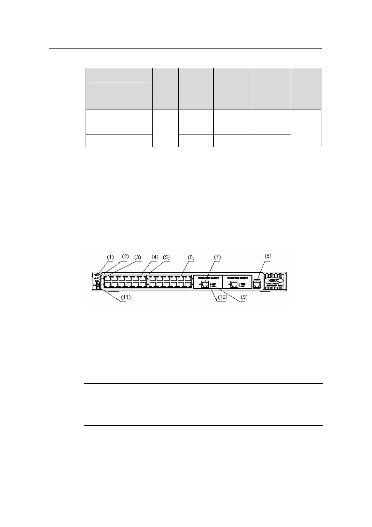
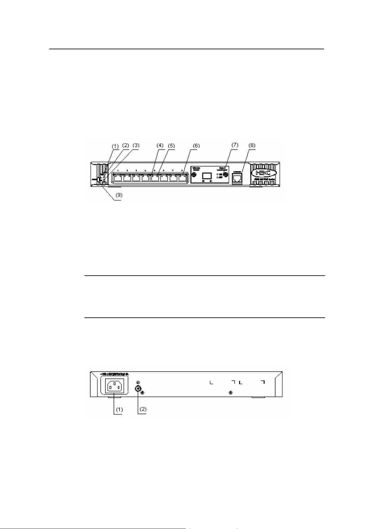
1.2.1 S3100-26T-SI
I. Front panel
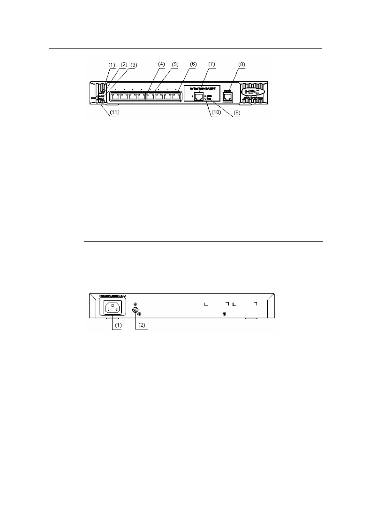
S3100-26T-SI Ethernet switches each provide twenty-four auto-sensing
10/100Base-TX Ethernet ports, two 10/100/1000Base-T Ethernet ports, and one
console port.
Figure 1-1 shows the front panel of an S3100-26T-SI Ethernet switch.
Number
of
console
ports
1
(1) Power LED (2) A/L LED
(3) D/S LED (4) Port status LED, left (yellow)
(5) Port status LED, right (green) (6) 10/100 Base-TX port
(7) 10/100/1000 Base-T port (8) Console port
(9) LINK LED (green) (10) ACT LED (yellow)
(11) Mode button
Figure 1-1 Front panel of an S3100-26T-SI Ethernet switch
Note:
For details about LEDs on the front panel, refer to section 1.4.1 “Front Panel LEDs of
the S3100-SI/S3100-TP-PWR-EI/S3100-C-EPON-EI Series”.
1-3
Page 11
Installation Manual
H3C S3100 Series Ethernet Switches Chapter 1 Product Introduction
II. Rear panel
Figure 1-2 shows the rear panel of an S3100-26T-SI Ethernet switch.
(1) AC power socket (2) Grounding screw
Figure 1-2 Rear panel of an S3100-26T-SI Ethernet switch
III. Power system
S3100-26T-SI Ethernet switches support AC input.
z Rated voltage range: 100 VAC to 240 VAC, 50 Hz/60 Hz
z Input voltage range: 90 VAC to 264 VAC, 47 Hz to 63 Hz
IV. Cooling system
The S3100-26T-SI cools off naturally.
1.2.2 S3100-16T-SI
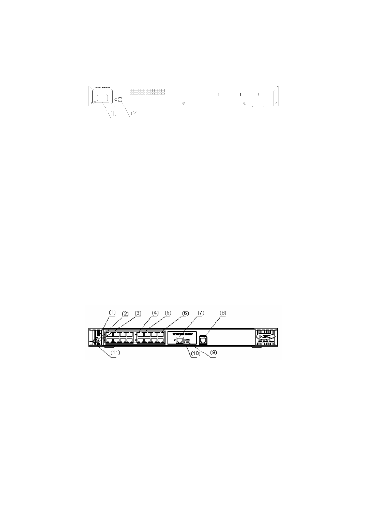
I. Front panel
S3100-16T-SI Ethernet switches each provide sixteen auto-sensing 10/100Base-TX
Ethernet ports, one 10/100/1000Base-T Ethernet port, and one console port.
Figure 1-3 shows the front panel of an S3100-16T-SI Ethernet switch.
(1) Power LED (2) A/L LED
(3) D/S LED (4) Port status LED, left (yellow)
(5) Port status LED, right (green) (6) 10/100 Base-TX port
(7) 10/100/1000 Base-T port (8) Console port
(9) LINK LED (green) (10) ACT LED (yellow)
(11) Mode button
Figure 1-3 Front panel of an S3100-16T-SI Ethernet switch
1-4
Page 12
Installation Manual
H3C S3100 Series Ethernet Switches Chapter 1 Product Introduction
Note:
For details about LEDs on the front panel, refer to section 1.4.1 “Front Panel LEDs of
the S3100-SI/S3100-TP-PWR-EI/S3100-C-EPON-EI Series”.
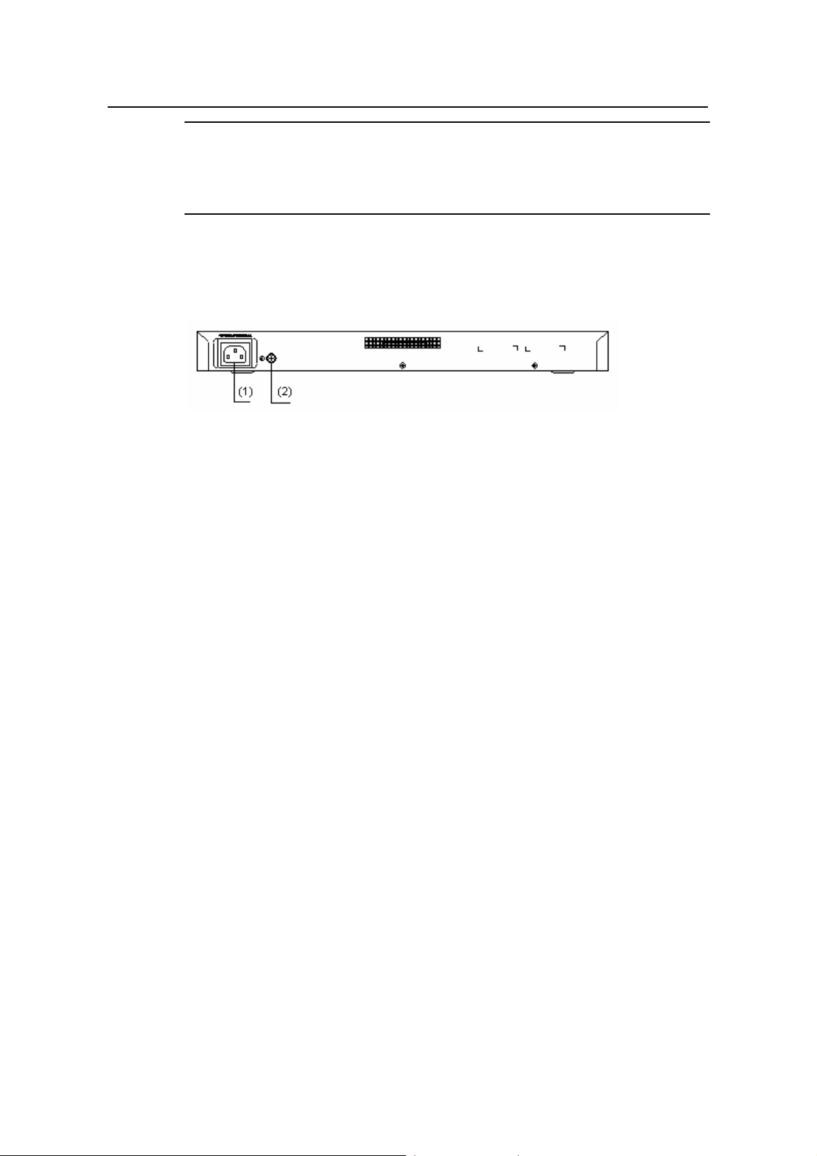
II. Rear panel
Figure 1-4 shows the rear panel of an S3100-16T-SI Ethernet switch.
(1) AC power socket (2) Grounding screw
Figure 1-4 Rear panel of an S3100-16T-SI Ethernet switch
III. Power system
S3100-16T-SI Ethernet switches support AC input.
z Rated voltage range: 100 VAC to 240 VAC, 50 Hz/60 Hz
z Input voltage range: 90 VAC to 264 VAC, 47 Hz to 63 Hz
IV. Cooling system
The S3100-16T-SI cools off naturally.
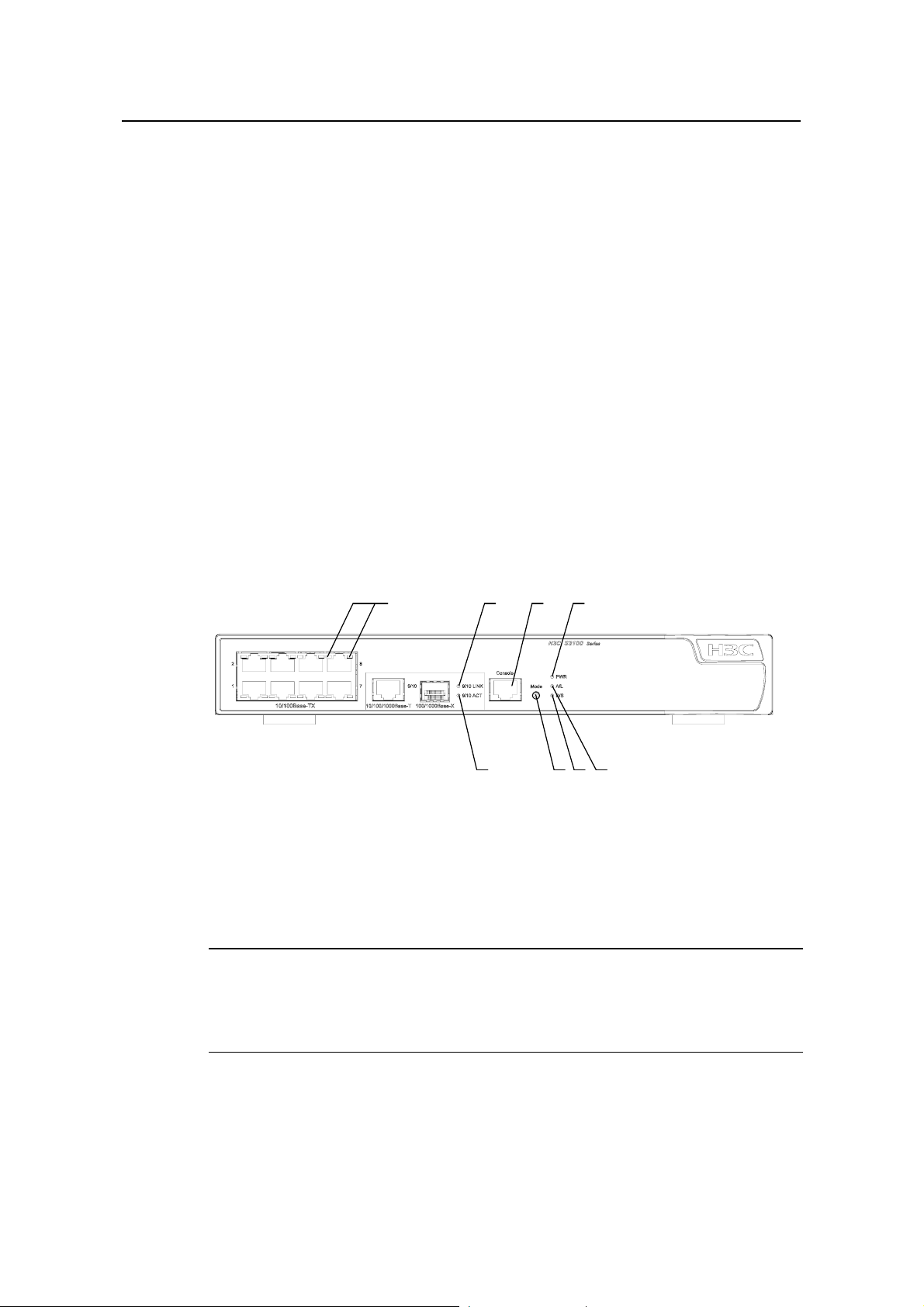
1.2.3 S3100-8T-SI
I. Front panel
S3100-8T-SI Ethernet switches each provide eight auto-sensing 10/100Base-TX
Ethernet ports, one 10/100/1000Base-T Ethernet port, and one console port.
Figure 1-5 shows the front panel of an S3100-8T-SI Ethernet switch.
1-5
Page 13
Installation Manual
H3C S3100 Series Ethernet Switches Chapter 1 Product Introduction
(1) Power LED (2) A/L LED
(3) D/S LED (4) Port status LED, left (yellow)
(5) Port status LED, right (green) (6) 10/100 Base-TX port
(7) 10/100/1000 Base-T port (8) Console port
(9) LINK LED (green) (10) ACT LED (yellow)
(11) Mode button
Figure 1-5 Front panel of an S3100-8T-SI Ethernet switch
Note:
For details about LEDs on the front panel, refer to section 1.4.1 “Front Panel LEDs of
the S3100-SI/S3100-TP-PWR-EI/S3100-C-EPON-EI Series”.
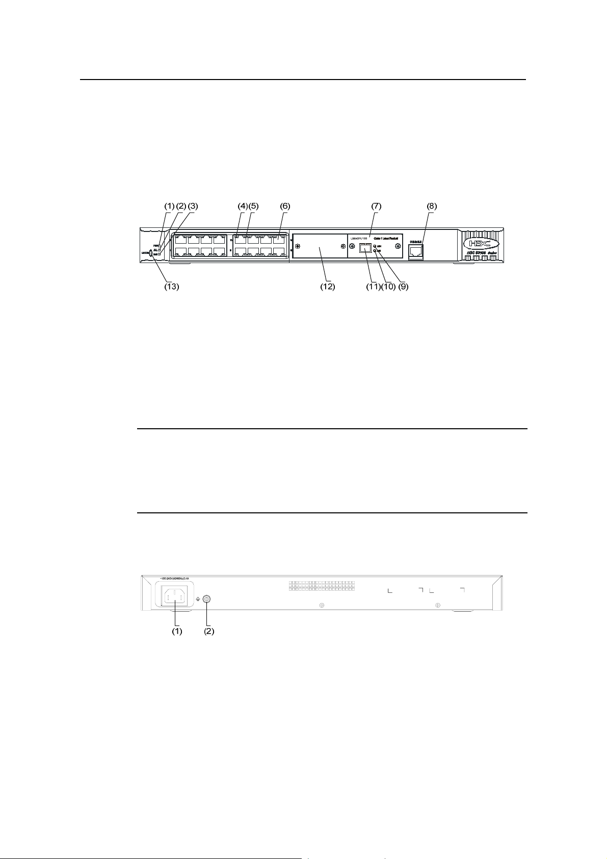
II. Rear panel
Figure 1-6 shows the rear panel of an S3100-8T-SI Ethernet switch.
(1) AC power socket (2) Grounding screw
Figure 1-6 Rear panel of an S3100-8T-SI Ethernet switch
III. Power system
S3100-8T-SI Ethernet switches support AC input.
z Rated voltage range: 100 VAC to 240 VAC, 50 Hz/60 Hz
z Input voltage range: 90 VAC to 264 VAC, 47 Hz to 63 Hz
IV. Cooling system
The S3100-8T-SI cools off naturally.
1-6
Page 14
Installation Manual
H3C S3100 Series Ethernet Switches Chapter 1 Product Introduction
1.2.4 S3100-26C-SI
Both AC-powered switch es and DC-powered switches are available to this model.
I. Front panel
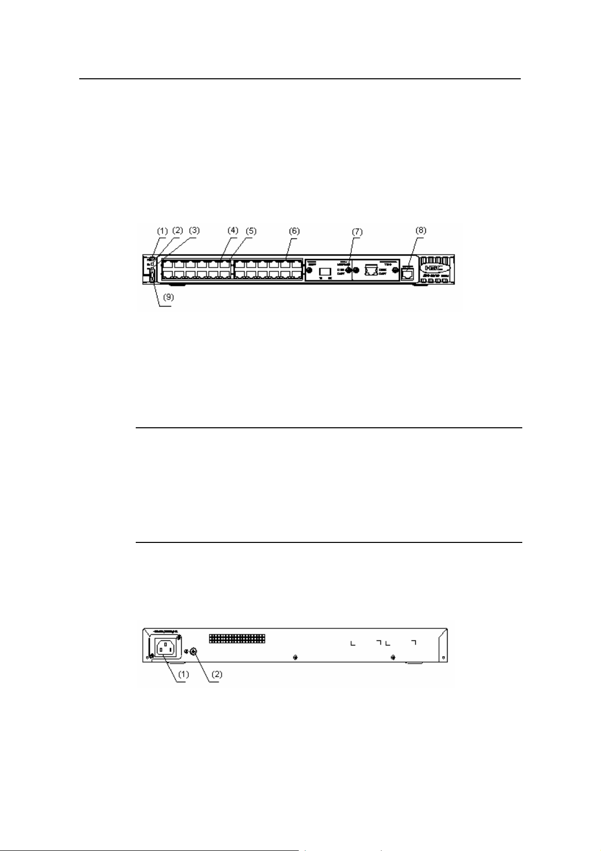
S3100-26C-SI Ethernet switches each provide twenty-four auto-sensing
10/100Base-TX Ethernet ports, two expansion slots, and one console port.
S3100-26C-SI Ethernet switches have the same front panel, as shown in
Figure 1-7.
(1) Power LED (2) A/L LED
(3) D/S LED (4) Port status LED, left (yellow)
(5) Port status LED, right (green) (6) 10/100Base- TX port
(7) Expansion slot (8) Console port
(9) Mode button
Figure 1-7 Front panel of an S3100-26C-SI Ethernet switch
Note:
z With a PoE card inserted in one expansion slot, an S3100-26C-SI Ethernet switch
will be a powered device (PD). In this case, the other expansion slot becomes
unavailable.
z For details about LEDs on the front panel, refer to section 1.4.1 “Front Panel LE Ds
of the S3100-SI/S3100-TP-PWR-EI/S3100-C-EPON-EI Series”.
II. Rear panel
Figure 1-8 shows the rear panel of an S3100-26C-SI AC-powered Ethernet switch.
(1) AC power socket (2) Grounding screw
Figure 1-8 Rear panel of an S3100-26C-SI AC-powered Ethernet switch
1-7
Page 15
Installation Manual
H3C S3100 Series Ethernet Switches Chapter 1 Product Introduction
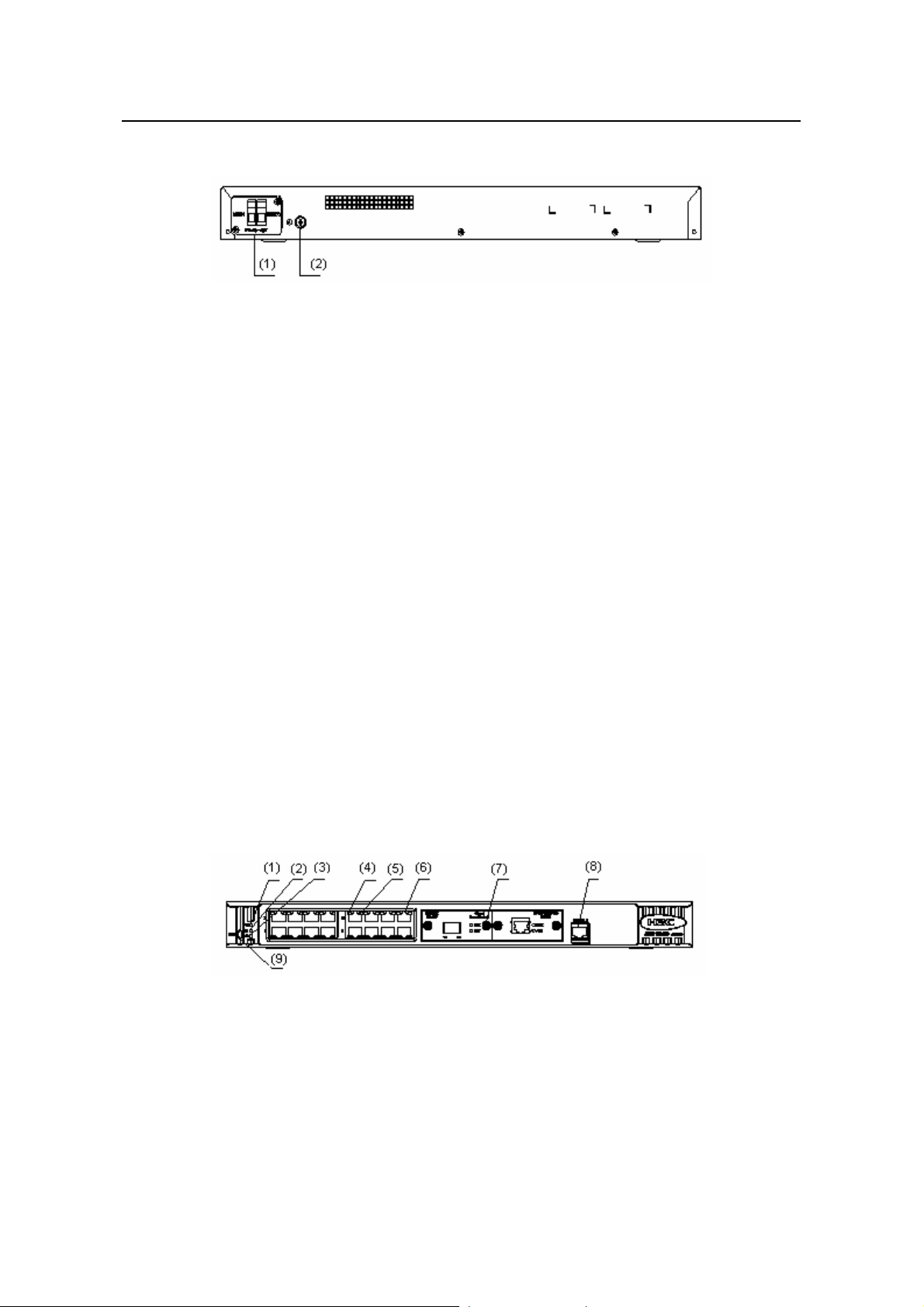
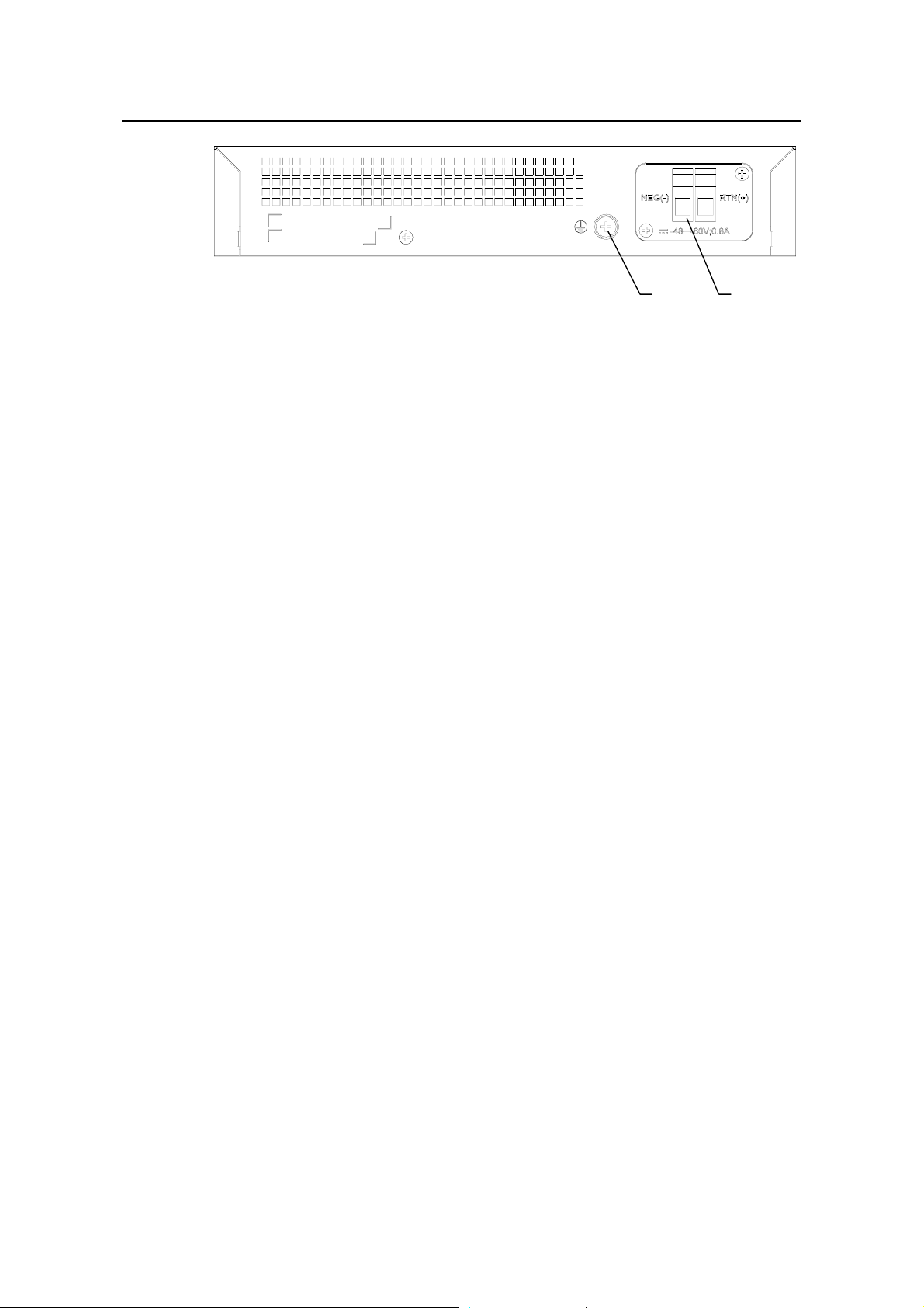
Figure 1-9 shows the rear panel of an S3100-26C-SI DC-powered Ethernet switch.
(1) DC input terminal block (2) Grounding screw
Figure 1-9 Rear panel of an S3100-26C-SI DC-powered Ethernet switch
III. Power system
1) S3100-26C-SI AC-powered Ethernet switches:
z Rated voltage range: 100 VAC to 240 VAC, 50 Hz/60 Hz
z Input voltage range: 90 VAC to 264 VAC, 47 Hz to 63 Hz
2) S3100-26C-SI DC-powered Ethernet switches:
z Rated voltage range: –48 VDC to –60 VDC
z Input voltage range: –36 VDC to –72 VDC
IV. Cooling system
The S3100-26C-SI cools off naturally.
1.2.5 S3100-16C-SI
Both AC-powered switch es and DC-powered switches are available to this model.
I. Front panel
S3100-16C-SI Ethernet switches each provide sixteen auto-sensing 10/100Base-TX
Ethernet ports, two expansion slots, and one console port.
S3100-16C-SI Ethernet switches have the same front panel, as shown in
(1) Power LED (2) A/L LED
(3) D/S LED (4) Port status LED, left (yellow)
(5) Port status LED, right (green) (6) 10/100Base- TX port
(7) Expansion slot (8) Console port
(9) Mode button
Figure 1-10.
Figure 1-10 Front panel of an S3100-16C-SI Ethernet switch
1-8
Page 16
Installation Manual
H3C S3100 Series Ethernet Switches Chapter 1 Product Introduction
Note:
z With a PoE card inserted in one expansion slot, an S3100-16C-SI Ethernet switch
will be a powered device (PD). In this case, the other expansion slot becomes
unavailable.
z For details about LEDs on the front panel, refer to section 1.4.1 “Front Panel LE Ds
of the S3100-SI/S3100-TP-PWR-EI/S3100-C-EPON-EI Series”.
II. Rear panel
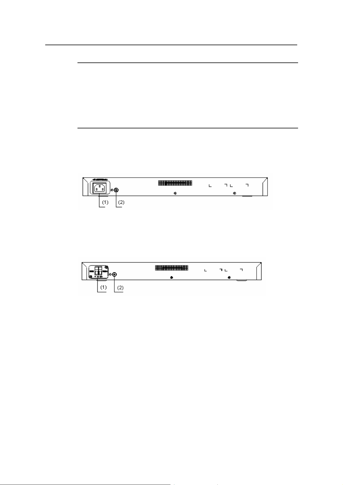
Figure 1-11 shows the rear panel of an S3100-16C-SI AC-powered Ethernet switch.
(1) AC power socket (2) Grounding screw
Figure 1-11 Rear panel of an S3100-16C-SI AC-powered Ethernet switch
Figure 1-12 shows the rear panel of an S3100-16C-SI DC-powered Ethernet switch.
(1) DC input terminal block (2) Grounding screw
Figure 1-12 Rear panel of an S3100-16C-SI DC-powered Ethernet switch
III. Power system
1) S3100-16C-SI AC-powered Ethernet switches:
z Rated voltage range: 100 VAC to 240 VAC, 50 Hz/60 Hz
z Input voltage range: 90 VAC to 264 VAC, 47 Hz to 63 Hz
2) S3100-16C-SI DC-powered Ethernet switches:
z Rated voltage range: –48 VDC to –60 VDC
z Input voltage range: –36 VDC to –72 VDC
IV. Cooling system
The S3100-16C-SI cools off naturally.
1-9
Page 17
Installation Manual
H3C S3100 Series Ethernet Switches Chapter 1 Product Introduction
1.2.6 S3100-8C-SI
Both AC-powered switch es and DC-powered switches are available to this model.
I. Front panel
S3100-8C-SI Ethernet switches each provide eight auto-sensing 10/100Base-TX
Ethernet ports, one expansion slot, and one console port.
S3100-8C-SI Ethernet switches have the same front panel, as shown in
Figure 1-13.
(1) Power LED (2) A/L LED
(3) D/S LED (4) Port status LED, left (yellow)
(5) Port status LED, right (green) (6) 10/100Base- TX port
(7) Expansion slot (8) Console port
(9) Mode button
Figure 1-13 Front panel of an S3100-8C-SI Ethernet switch
Note:
For details about LEDs on the front panel, refer to section 1.4.1 “Front Panel LEDs of
the S3100-SI/S3100-TP-PWR-EI/S3100-C-EPON-EI Series”.
II. Rear panel
Figure 1-14 shows the rear panel of an S3100-8C-SI AC-powered Ethernet switch.
(1) AC power socket (2) Grounding screw
Figure 1-14 Rear panel of an S3100-8C-SI AC-powered Ethernet switch
1-10
Page 18

Installation Manual
H3C S3100 Series Ethernet Switches Chapter 1 Product Introduction
Figure 1-15 shows the rear panel of an S3100-8C-SI DC-powered Ethernet switch.
(1) DC input terminal block (2) Grounding screw
Figure 1-15 Rear panel of an S3100-8C-SI DC-powered Ethernet switch
III. Power system
1) S3100-8C-SI AC-powered Ethernet switches:
z Rated voltage range: 100 VAC to 240 VAC, 50 Hz/60 Hz
z Input voltage range: 90 VAC to 264 VAC, 47 Hz to 63 Hz
2) S3100-8C-SI DC-powered Ethernet switches:
z Rated voltage range: –48 VDC to –60 VDC
z Input voltage range: –36 VDC to –72 VDC
IV. Cooling system
The S3100-8C-SI cools off naturally.
1.3 Introduction to S3100-EI Series Ethernet Switches
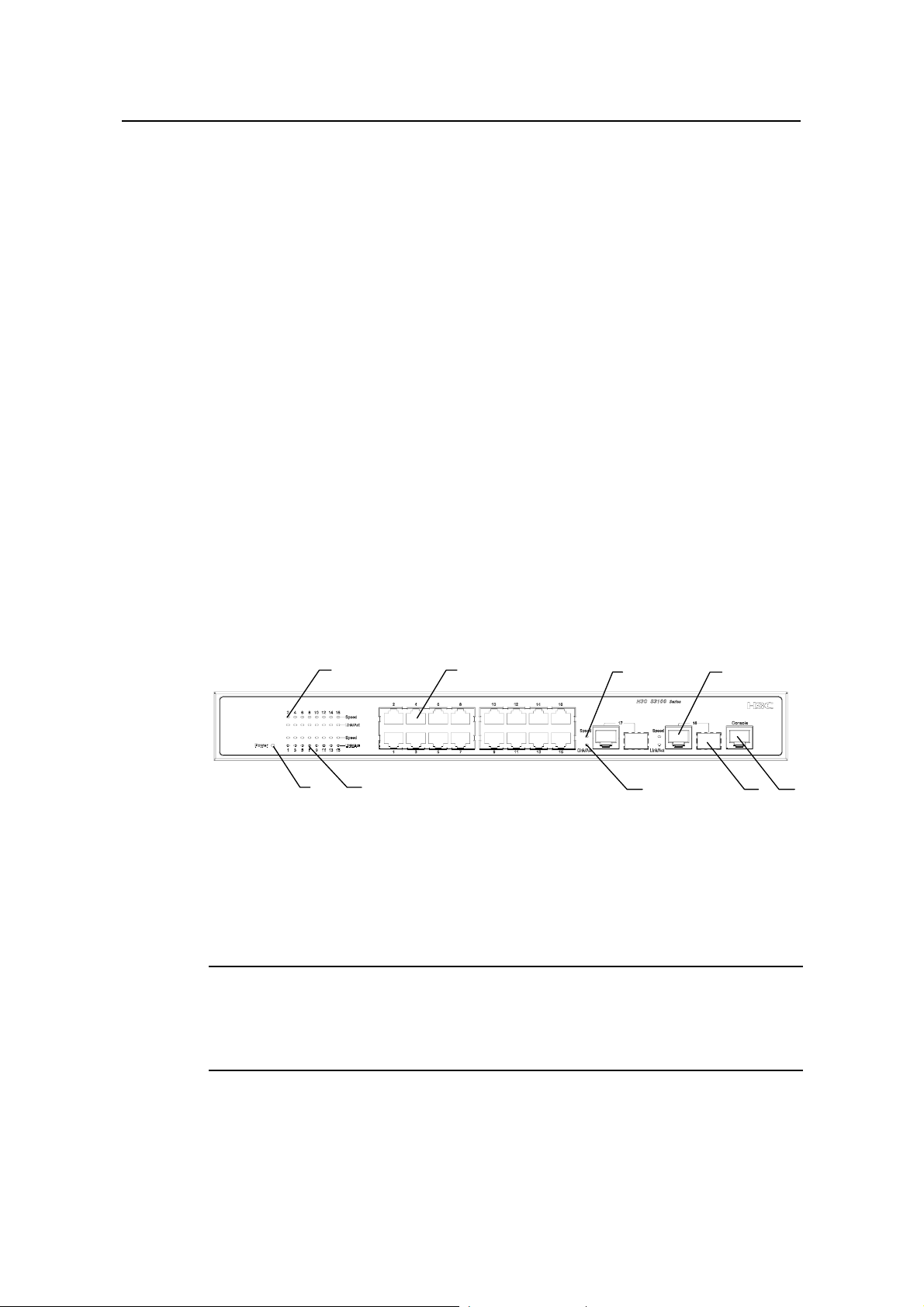
1.3.1 S3100-26TP-EI
Both AC-powered switch es and DC-powered switches are available to this model.
I. Front panel
S3100-26TP-EI Ethernet switches each provide twenty-four auto-sensing
10/100Base-TX Ethernet ports, two auto-sensing 10/100/1000Base-T Ethernet ports,
two 100/1000Base-X SFP ports, and one console port. Each SFP port and the
corresponding auto-sensing 10/100/1000Base- T Ethernet port form a Combo port. For
each Combo port, either the SFP port or the corresponding 10/100/1000Base- T
Ethernet port can be used at a time.
S3100-26TP-EI Ethernet switches have the same front panel, as shown in
Figure 1-16.
1-11
Page 19

Installation Manual
H3C S3100 Series Ethernet Switches Chapter 1 Product Introduction
(1) (2) (4)
(7)
(1) Auto-sensing 10/100Base-TX port Speed LED (green)
(2) Auto-sensing 10/100Base-TX port (3) Combo port Speed LED (green)
(4) Auto-sensing 10/100/1000Base-T port (5) Console port
(6) 100/1000Base-X SFP port (7) LINK/ACT LED (green)
(8) Power LED (PWR)
(3)
(7)(8)
(6)
(5)
Figure 1-16 Front panel of an S3100-26TP-EI Ethernet switch
Note:
For details about LEDs on the front panel, refer to section 1.4.2 Front Panel LEDs of
the S3100-TP-EI Series .
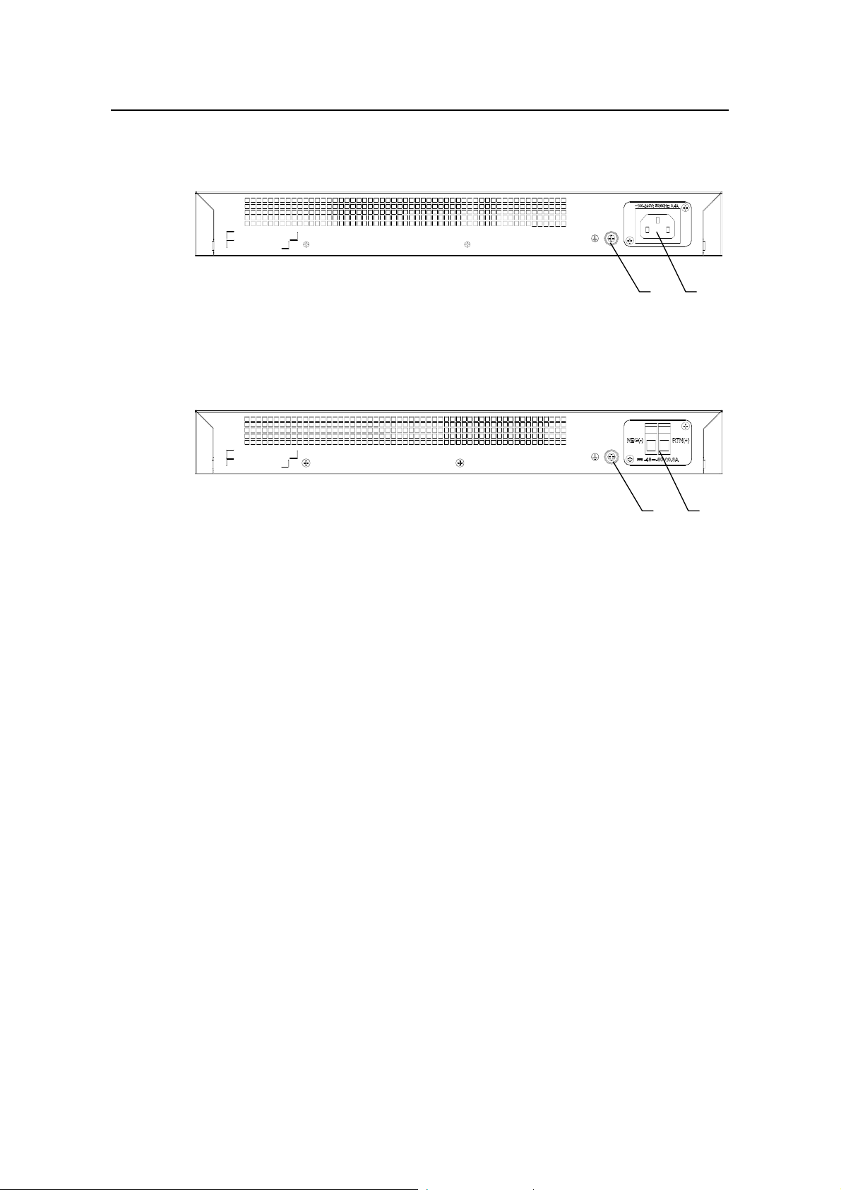
II. Rear panel
Figure 1-17 shows the rear panel of an S3100-26TP-EI AC-powered Ethernet switch.
(1) (2)
(1) Grounding screw (2) AC input terminal block
Figure 1-17 Rear panel of an S3100-26TP-EI AC-powered Ethernet switch
Figure 1-18 shows the rear panel of an S3100-26TP-EI DC-powered Ethernet switch.
(1) (2)
(1) Grounding screw (2) DC input terminal block
Figure 1-18 Rear panel of an S3100-26TP-EI DC-powered Ethernet switch
III. Power system
1) S3100-26TP-EI AC-powered Ethernet switches:
1-12
Page 20
Installation Manual
(
1)(
2
H3C S3100 Series Ethernet Switches Chapter 1 Product Introduction
z Rated voltage range: 100 VAC to 240 VAC, 50 Hz/60 Hz
z Input voltage range: 90 VAC to 264 VAC, 47 Hz to 63 Hz
2) S3100-26TP-EI DC-powered Ethernet switches:
z Rated voltage range: –48 VDC to –60 VDC
z Input voltage range: –36 VDC to –72 VDC
IV. Cooling system
The S3100-26TP-EI cools off naturally.
1.3.2 S3100-16TP-EI
Both AC-powered switch es and DC-powered switches are available to this model.
I. Front panel
S3100-16TP-EI Ethernet switches each provide sixteen auto-sensing 10/100Base-TX
Ethernet ports, two auto-sensing 10/100/1000Base-T Ethernet ports, two
100/1000Base-X SFP ports, and one console port. Each SFP port and the
corresponding auto-sensing 10/100/1000Base- T Ethernet port form a Combo port. For
each Combo port, either the SFP port or the corresponding 10/100/1000Base- T
Ethernet port can be used at a time.
S3100-16TP-EI Ethernet switches have the same front panel, as shown in
)
(7)
(8)
(1) Auto-sensing 10/100Base-TX port Speed LED (green)
(2) Auto-sensing 10/100Base-TX port (3) Combo port Speed LED (green)
(4) Auto-sensing 10/100/1000Base-T port (5) Console port
(6) 100/1000Base-X SFP port (7) LINK/ACT LED (green)
(8) Power LED (PWR)
(3)
(7)
Figure 1-19.
(4)
(6)
(5)
Figure 1-19 Front panel of an S3100-16TP-EI Ethernet switch
Note:
For details about LEDs on the front panel, refer to section 1.4.2 Front Panel LEDs of
the S3100-TP-EI Series
1-13
Page 21
Installation Manual
H3C S3100 Series Ethernet Switches Chapter 1 Product Introduction
II. Rear panel
Figure 1-20 shows the rear panel of an S3100-16TP-EI AC-powered Ethernet switch.
(1) (2)
(1) Grounding screw (2) AC input terminal block
Figure 1-20 Rear panel of an S3100-16TP-EI AC-powered Ethernet switch
Figure 1-21 shows the rear panel of an S3100-16TP-EI DC-powered Ethernet switch.
(1) (2)
(1) Grounding screw (2) DC input terminal block
Figure 1-21 Rear panel of an S3100-16TP-EI DC-powered Ethernet switch
III. Power system
1) S3100-16TP-EI AC-powered Ethernet switches:
z Rated voltage range: 100 VAC to 240 VAC, 50 Hz/60 Hz
z Input voltage range: 90 VAC to 264 VAC, 47 Hz to 63 Hz
2) S3100-16TP-EI DC-powered Ethernet switches:
z Rated voltage range: –48 VDC to –60 VDC
z Input voltage range: –36 VDC to –72 VDC
IV. Cooling system
The S3100-16TP-EI cools off naturally.
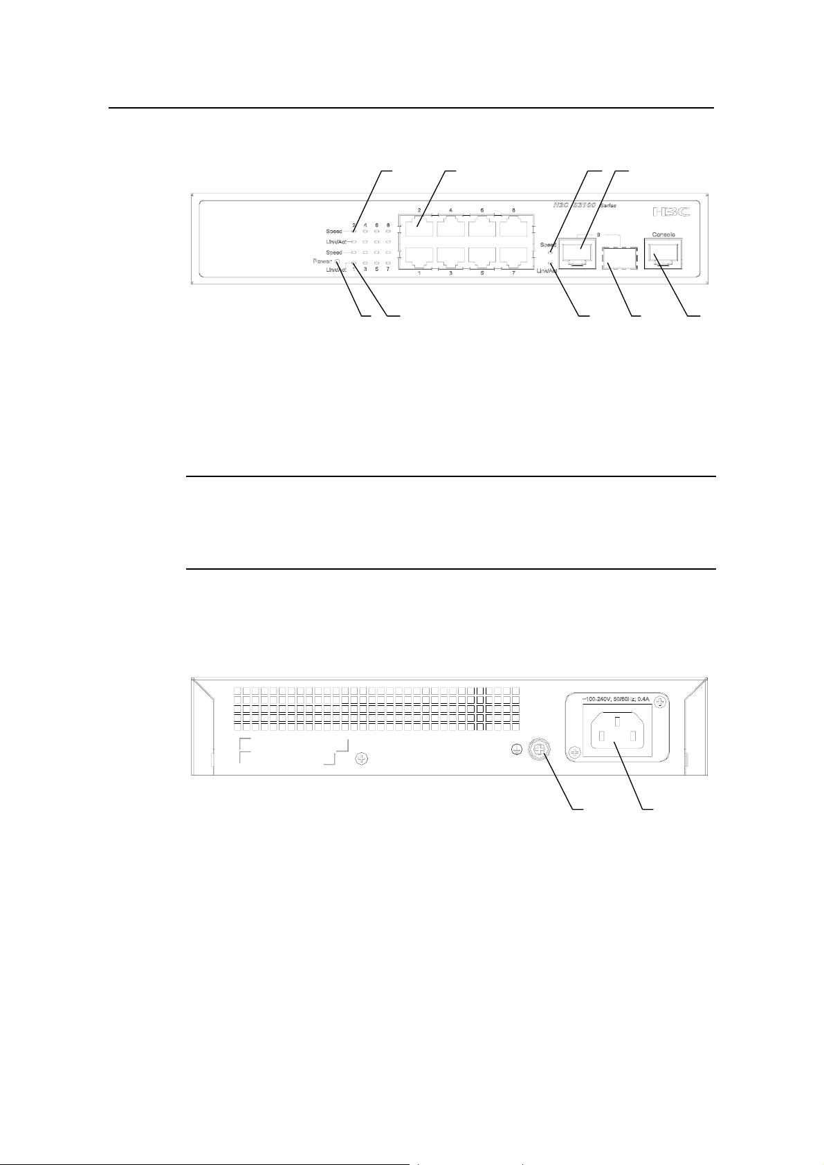
1.3.3 S3100-8TP-EI
Both AC-powered switch es and DC-powered switches are available to this model.
I. Front panel
S3100-8TP-EI Ethernet switches each provide eight auto-sensing 10/100Base-TX
Ethernet ports, one auto-sensing 10/100/1000Base-T Ethernet ports, one
100/1000Base-X SFP ports, and one consol e port. The SFP port and the auto-sensing
10/100/1000Base- T Ethernet port form a Combo port. For the Combo port, either the
SFP port or the 10/100/1000Base- T Ethernet port can be used at a time.
1-14
Page 22
Installation Manual
H3C S3100 Series Ethernet Switches Chapter 1 Product Introduction
S3100-8TP-EI Ethernet switches have the same front panel, as shown in Figure 1-22.
(1) (2) (4)
(7)
(1) Auto-sensing 10/100Base-TX port Speed LED (green)
(2) Auto-sensing 10/100Base-TX port (3) Combo port Speed LED (green)
(4) Auto-sensing 10/100/1000Base-T port (5) Console port
(6) 100/1000Base-X SFP port (7) LINK/ACT LED (green)
(8) Power LED (PWR)
(3)
(6)(7)(8)
(5)
Figure 1-22 Front panel of an S3100-8TP-EI Ethernet switch
Note:
For details about LEDs on the front panel, refer to section 1.4.2 Front Panel LEDs of
the S3100-TP-EI Series .
II. Rear panel
Figure 1-23 shows the rear panel of an S3100-8TP-EI AC-powered Ethernet switch.
(1) (2)
(1) Grounding screw (2) AC input terminal block
Figure 1-23 Rear panel of an S3100-8TP-EI AC-powered Ethernet switch
Figure 1-24 shows the rear panel of an S3100-8TP-EI DC-powered Ethernet switch.
1-15
Page 23
Installation Manual
H3C S3100 Series Ethernet Switches Chapter 1 Product Introduction
(1) (2)
(1) Grounding screw (2) DC input terminal block
Figure 1-24 Rear panel of an S3100-8TP-EI DC-powered Ethernet switch
III. Power system
1) S3100-8TP-EI AC-powered Ethernet switches:
z Rated voltage range: 100 VAC to 240 VAC, 50 Hz/60 Hz
z Input voltage range: 90 VAC to 264 VAC, 47 Hz to 63 Hz
2) S3100-8TP-EI DC-powered Ethernet switches:
z Rated voltage range: –48 VDC to –60 VDC
z Input voltage range: –36 VDC to –72 VDC
IV. Cooling system
The S3100-8TP-EI cools off naturally.
1.3.4 S3100-26TP-PWR-EI
I. Front panel
S3100-26TP-PWR-EI Ethernet switches each provide twenty-four auto-sensing
10/100Base-TX Ethernet ports, two 10/100/1000Base-T Ethernet ports, two
100/1000Base SFP ports, and one console port. Each SFP port an d the corresponding
10/100/1000Base- T Ethernet port form a Combo port. For each Combo po rt, either the
SFP port or the corresponding 10/100/1000Base- T Ethernet port can be used at a
time.
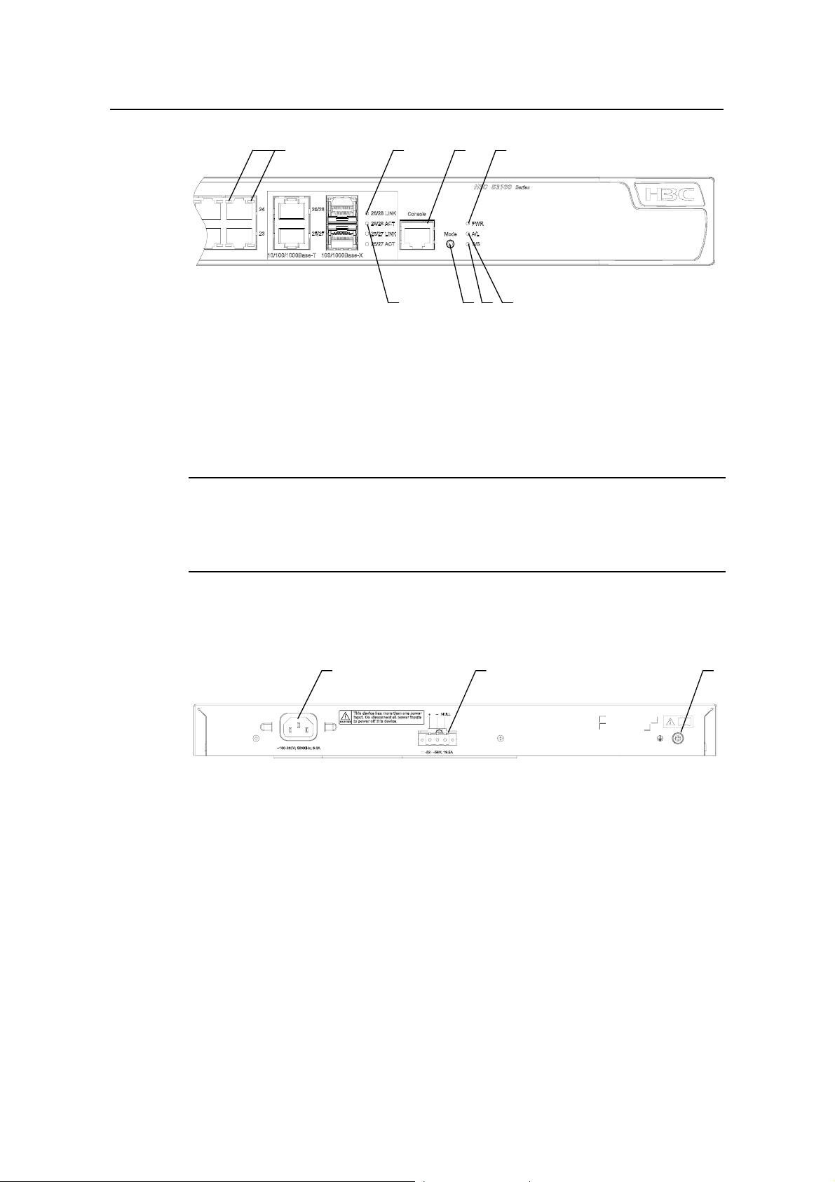
Figure 1-25 shows the front panel of an S3100-26TP-PWR-EI Ethernet switch.
1-16
Page 24
Installation Manual
H3C S3100 Series Ethernet Switches Chapter 1 Product Introduction
(1) (2) (3) (4)
(5)(6)(7)(8)
(1) Auto-sensing 10/100Base-TX Ethernet port status LED
(2) LINK LED for Combo port (3) Console port
(4) Power LED (PWR) (5) A/L LED
(6) D/S LED (7) Mode button
(8) ACT LED for Combo port
Figure 1-25 Front panel of an S3100-26TP-PWR-EI Ethernet switch
Note:
For details about LEDs on the front panel, refer to section 1.4.1 “Front Panel LEDs of
the S3100-SI/S3100-TP-PWR-EI/S3100-C-EPON-EI Series”.
II. Rear panel
(1) (2) (3)
(1) AC power socket (2) DC power socket
(3) Grounding screw
Figure 1-26 Rear panel of an S3100-26TP-PWR-EI Ethernet switch
III. Power system
S3100-26TP-PWR-EI Ethernet switches support AC input or DC input.
1) AC input
z Rated voltage range: 100 VAC to 240 VAC, 50 Hz/60 Hz
z Input voltage range: 90 VAC to 264 VAC, 47 Hz to 63 Hz
2) DC input
z Rated voltage range: –52 VDC to –56 VDC
1-17
Page 25
Installation Manual
H3C S3100 Series Ethernet Switches Chapter 1 Product Introduction
Note:
Only the recommended RPS can be used for S3100-26TP-PWR-EI Ethernet switches.
The –48 VDC in the equipment room cannot be used directly. Otherwise, the device
may be damaged.
IV. Cooling system
The S3100-26TP-PWR-EI has four fans for heat dissipation.
1.3.5 S3100-16TP-PWR-EI
I. Front panel
S3100-16TP-PWR-EI Ethernet switches each provide sixteen auto-sensing
10/100Base-TX Ethernet ports, two 10/100/1000Base-T Ethernet ports, two
100/1000Base SFP ports, and one console port. Each SFP port an d the corresponding
10/100/1000Base-T Ethernet port form a Combo port. For e ach Combo port, eith er the
SFP port or the corresponding 10/100/1000Base-T Ethern et port can be used at a time.
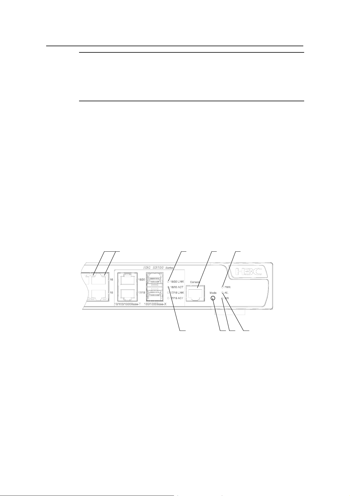
Figure 1-27 shows the front panel of an S3100-16TP-PWR-EI Ethernet switch.
(1) (2) (3) (4)
(5)(6)(7)(8)
(1) Auto-sensing 10/100Base-TX Ethernet port status LED
(2) LINK LED for Combo port (3) Console port
(4) Power LED (PWR) (5) A/L LED
(6) D/S LED (7) Mode button
(8) ACT LED for Combo port
Figure 1-27 Front panel of an S3100-16TP-PWR-EI Ethernet switch
1-18
Page 26
Installation Manual
H3C S3100 Series Ethernet Switches Chapter 1 Product Introduction
Note:
For details about LEDs on the front panel, refer to section 1.4.1 “Front Panel LEDs of
the S3100-SI/S3100-TP-PWR-EI/S3100-C-EPON-EI Series”.
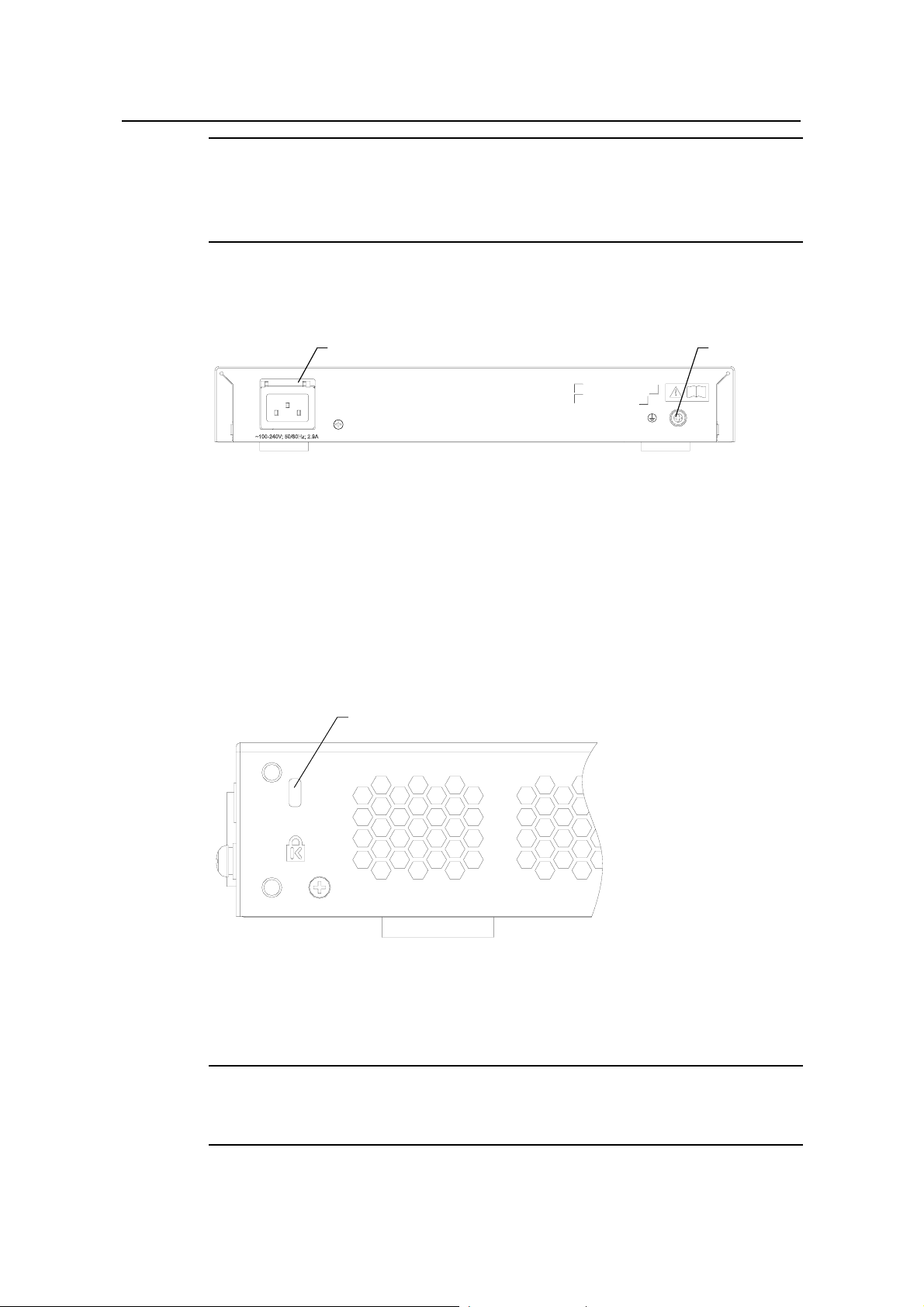
II. Rear panel
(1) (2)
(1) AC power socket (2) Grounding screw
Figure 1-28 Rear panel of an S3100-16TP-PWR-EI Ethernet switch
III. Side panel
Each S3100-16TP-PWR-EI Ethernet switch provides a security slot , through which you
can lock the device together with an irremovable object to prevent theft.
The security slot is located at the rear end of the left side panel, as shown in
Figure
1-29.
(1)
(1) Security slot
Figure 1-29 Security slot on left side panel of an S3100-16TP-PWR-EI Ethernet switch
Note:
If the left screw hole above the security slot is used, the security slot cannot be used.
1-19
Page 27
Installation Manual
H3C S3100 Series Ethernet Switches Chapter 1 Product Introduction
IV. Power system
S3100-16TP-PWR-EI Ethernet switches support AC input.
z Rate voltage range: 100 VAC to 240 VAC, 50 Hz/60 Hz
z Input voltage range: 90 VAC to 264 VAC, 47 Hz to 63 Hz
V. Cooling system
The S3100-16TP-PWR-EI has two fans for heat dissipation.
1.3.6 S3100-8TP-PWR-EI
I. Front panel
S3100-8TP-PWR-EI Ethernet switches each provide eight auto-sensing
10/100Base-TX Ethernet ports, one 10/100/1000Base-T Ethernet port, one
100/1000Base SFP ports, and one console port. The SFP port and the
10/100/1000Base-T Ethernet port form a Combo port. Either the SFP port or the
10/100/1000Base-T Ethernet port can be used at a time.
Figure 1-30 shows the front panel of an S3100-8TP-PWR-EI Ethernet switch.
(1) (2) (3) (4)
(5)(6)(7)(8)
(1) Auto-sensing 10/100Base-TX Ethernet port status LED
(2) LINK LED for Combo port (3) Console port
(4) Power LED (PWR) (5) A/L LED
(6) D/S LED (7) Mode button
(8) ACT LED for Combo port
Figure 1-30 Front panel of an S3100-8TP-PWR-EI Ethernet switch
Note:
For details about LEDs on the front panel, refer to section 1.4.1 “Front Panel LEDs of
the S3100-SI/S3100-TP-PWR-EI/S3100-C-EPON-EI Series”.
1-20
Page 28

Installation Manual
H3C S3100 Series Ethernet Switches Chapter 1 Product Introduction
II. Rear panel
(1) (2)
(1) AC power socket (2) Grounding screw
Figure 1-31 Rear panel of an S3100-8TP-PWR-EI Ethernet switch
III. Side panel
Each S3100-8TP-PWR-EI Ethernet switch provides a security slot, through which you
can lock the device together with an irremovable object to prevent theft.
The security slot is located at the rear end of the left side panel, as shown in
1-29.
Note:
If the left screw hole above the security slot is used, the security slot cannot be used.
IV. Power system
S3100-8TP-PWR-EI Ethernet switches support AC input.
z Rate voltage range: 100 VAC to 240 VAC, 50 Hz/60 Hz
z Input voltage range: 90 VAC to 264 VAC, 47 HZ to 63 Hz
V. Cooling system
The S3100-8TP-PWR-EI has two fans for heat dissipation.
1.3.7 S3100-26C-EPON-EI
Figure
I. Front panel
The S3100-26C-EPON-EI provides 24 x 10/100Base-TX ports, one Gigabit uplink PON
port, one expansion slot, and one console port.
Figure 1-32 shows the front view of the S3100-26C-EPON-EI.
1-21
Page 29

Installation Manual
H3C S3100 Series Ethernet Switches Chapter 1 Product Introduction
(1): Power Led (PWR) (2): A/L LED
(3): D/S LED (4): Port status LED, left (yellow)
(5): Port status LED, right (green) (6): 10/100 Base-TX port
(7): ONU module (8): Console port
(9): LINK LED for the uplink PON port (10): ACT LED for the uplink PON port
(11): 1000 Mbps uplink PON port (12): Expansion slot
(13): MODE button
Figure 1-32 Front panel of the S3100-26C-EPON-EI
Note:
z The S3100-26C-EPON-EI provides one expansion slot. You can order one more
ONU module (1000Base- PX20) as needed. For more information about ONU
modules, refer to section
z For details about the LEDs on the front panel, refer to section 1.4.1 “Front Panel
1.7 “ONU Modules”.
LEDs of the S3100-SI/S3100-TP-PWR-EI/S3100-C-EPON-EI Series”.
II. Rear panel
(1) AC power socket (2) Grounding screw
Figure 1-33 Rear panel of an S3100-26C-EPON-EI Ethernet switch
III. Power system
S3100-26C-EPON-EI Ethernet switches support AC input.
z Rated voltage range: 100 VAC to 240 VAC, 50 Hz/60 Hz
z Input voltage range: 90 VAC to 264 VAC, 47 Hz to 63 Hz
IV. Cooling system
The S3100-26C-EPON-EI has one fan for heat dissipation.
1-22
Page 30
Installation Manual
H3C S3100 Series Ethernet Switches Chapter 1 Product Introduction
1.3.8 S3100-16C-EPON-EI
I. Front panel
The S3100-16C-EPON-EI provides 16 x 10/100Base-TX Ethernet ports, one 1000
Mbps uplink PON port, and one console port.
Figure 1-34 shows the front panel of the S3100-16C-EPON-EI.
(1): Power Led (PWR) (2): A/L LED
(3): D/S LED (4): Port status LED, left (yellow)
(5): Port status LED, right (green) (6): 10/100 Base-TX port
(7): ONU module (8): Console port
(9): LINK LED for the uplink PON port (10): ACT LED for the uplink PON port
(11): 1000 Mbps uplink PON port (12): Expansion slot (disabled)
(13): MODE button
Figure 1-34 Front panel of the S3100-16C-EPON-EI
Note:
z The S3100-16C-EPON-EI supports only one ONU module (required).
z For details about the LEDs on the front panel, refer to section 1.4.1 “Front Panel
LEDs of the S3100-SI/S3100-TP-PWR-EI/S3100-C-EPON-EI Series”.
II. Rear panel
(1) AC power socket (2) Grounding screw
Figure 1-35 Rear panel of an S3100-16C-EPON-EI Ethernet switch
III. Power system
S3100-16C-EPON-EI Ethernet switches support AC input.
z Rated voltage range: 100 VAC to 240 VAC, 50 Hz/60 Hz
z Input voltage range: 90 VAC to 264 VAC, 47 Hz to 63 Hz
1-23
Page 31

Installation Manual
H3C S3100 Series Ethernet Switches Chapter 1 Product Introduction
IV. Cooling system
The S3100-16C-EPON-EI cools off naturally.
1.3.9 S3100-8C-EPON-EI
I. Front panel
The S3100-8C-SI provides 8 x 10/100Base-TX Ethernet ports, one 1000 Mbps uplink
PON port, and one console port.
Figure 1-36 shows the front panel of the S3100-8C-EPON-EI.
(1): Power LED (PWR) (2): A/L LED
(3): D/S LED (4): Port status LED, left (yellow)
(5): Port status LED, right (green) (6): 10/100 Base-TX port
(7): ONU module (8): Console port
(9): Link LED for the uplink PON port (10): ACT LED for the uplink PON port
(11): 1000 Mbps uplink PON port (12): MODE button
Figure 1-36 Front panel of the S3100-8C-EPON-EI
Note:
For details about the LEDs on the front p anel, refer to section 1.4.1 “Front Pan el LEDs
of the S3100-SI/S3100-TP-PWR-EI/S3100-C-EPON-EI Series”.
II. Rear panel
(1) AC power socket (2) Grounding screw
Figure 1-37 Rear panel of an S3100-8C-EPON-EI Ethernet switch
III. Power system
S3100-8C-EPON-EI Ethernet switches support AC input.
1-24
Page 32

Installation Manual
H3C S3100 Series Ethernet Switches Chapter 1 Product Introduction
z Rated voltage range: 100 VAC to 240 VAC, 50 Hz/60 Hz
z Input voltage range: 90 VAC to 264 VAC, 47 Hz to 63 Hz
IV. Cooling system
The S3100-8C-EPON-EI cool off naturally.
1.4 Introduction to Front Panel LEDs
1.4.1 Front Panel LEDs of the S3100-SI/S3100-TP-PWR-EI/S3100-C-EPON-EI Series
I. Power LED
Table 1-6 Description of the power LED on S3100-SI, S3100-TP-PWR-EI and
S3100-C-EPON-EI series Ethernet switches
LED Mark on the panel Status Description
Power LED PWR
ON The switch is powered on.
OFF The switch is powered off.
II. Auto-sensing 10/100Base- TX Ethernet port status LED
There are two port status LEDs on both sides (yellow LED on the lef t and green LED on
the right) of each 10/100Base-TX Ethernet port of S3100-SI, S3100-TP-PWR-EI and
S3100-C-EPON-EI series. They indicate the active, link, duplex, and speed st atuses of
the port.
In addition, there are an A/L LED and a D/S LED on each model of S3100-SI,
S3100-TP-PWR-EI and S3100-C-EPON-EI series. These two LE Ds i ndicate th e mod e
of the port status LEDs. When the A/L LED is on, the port status LEDs respectively
indicate the active status and link status of ports. When the D/S LED is on, the port
status LEDs respectively indicate the duplex status and speed status of ports. Either
the A/L LED or the D/S LED is on at a specific time. For details, see
Table 1-7.
1-25
Page 33

Installation Manual
H3C S3100 Series Ethernet Switches Chapter 1 Product Introduction
Table 1-7 Description of port status LEDs on S3100-SI, S3100-TP-PWR-EI, and
S3100-C-EPON-EI series Ethernet switches
Port status
mode LED
The A/L
Port status LED Description
Yellow LED
Blinking
(left)
OFF
The port is in the active state and there
is traffic on the port.
The port is in the active state but there
is no traffic on the port.
LED is on
ON The port is connected properly.
Green LED
The port is not connected or is
incorrectly connected.
The port operates in the full duplex
mode.
The port operates in the half duplex
mode.
The D/S
LED is on
(right)
Yellow LED
(left)
Green LED
(right)
OFF
ON
OFF
ON The port rate is 100 Mbps.
OFF The port rate is 10 Mbps.
You can switch the mode of the port status LEDs by pressing the Mode button. After a
switch is powered on, the A/L LED is on initially. If you press the Mode button, the D/S
LED will be on. After that, if you press the Mode button again within 45 seconds, th e A/L
LED will be on again. Otherwise, the A/L LED will automatically be on 45 seconds later.
III. 1000 Mbps Uplink Port Status LED
Table 1-8 Description of 1000 Mbps uplink port status LED on S3100-SI,
S3100-TP-PWR-EI and S3100-C-EPON-EI series Ethernet switches
LED
1000 Mbps uplink
port link LED
Mark on the
panel
LINK
Status Description
ON
The port is connected
properly.
The port is not connected
OFF
or is incorrectly
connected.
The port is in the active
1000 Mbps uplink
port active LED
Blinking
ACT
OFF
state and there is traffic
on the port.
The port is in the active
state but there is no traffic
on the port.
1-26
Page 34

Installation Manual
H3C S3100 Series Ethernet Switches Chapter 1 Product Introduction
1.4.2 Front Panel LEDs of the S3100-TP-EI Series
I. Power LED
Table 1-9 Description of the power LED on the S3100-TP-EI series
LED Mark on the panel Status Description
Power LED Power
ON The switch is powered on.
OFF The switch is powered off.
II. Port LED
Table 1-10 describes the Link/Act LED of the auto-sensing 10/100Base-TX port.
Table 1-10 Description of the Link/Act LED on the S3100-TP-EI series
LED Status Description
ON The port is connected properly.
Link/Act LED (green)
Blinking
OFF
The port is in the active state and there
is traffic on the port.
The port is not connected or is
incorrectly connected.
Table 1-11 describes the Speed LED of the 10/100Base-TX port.
Table 1-11 Description of the 10/100Base-TX port Speed LED of the S3100-TP-EI
series
LED Status Description
ON The port is operating at 100 Mbps. Auto-sensing
10/100Base-TX port
speed LED (green)
OFF The port is operating at 10 Mbps.
For the description of the Link/Act LED of the Combo port, see
Table 1-10. When the
port is connected correctly, the Speed LED indicates the operating speeds of the
Combo port, as shown in
Table 1-12.
1-27
Page 35

Installation Manual
H3C S3100 Series Ethernet Switches Chapter 1 Product Introduction
Table 1-12 Description of the Combo port Speed LED of the S3100-TP-EI series
LED Operating port Status Description
Connected to a
1000 Mbps
100/1000Base
-X SFP port
Combo port
Speed LED
(green)
Auto-sensing
10/100/1000Base-T port
optical module
Connected to a
100 Mbps
optical module
1.5 Technical Specifications
1.5.1 S3100-SI Series Ethernet Switch
I. S3100-T-SI
Table 1-13 Technical specifications for the S3100-T-SI series
Item S3100-26T-SI S3100-16T-SI S3100-8T-SI
ON
OFF
ON
OFF
The port is operating
at 1000 Mbps.
The port is operating
at 100 Mbps.
The port is operating
at 1000 Mbps.
The port is operating
at 10/100 Mbps.
Physical
dimensions (H ×
W × D)
Weight ≤ 3.2 kg (7.1 lb.)
Number of fixed
ports
Number of
management ports
Power system
PoE (as powered
device)
System power
consumption (full
load)
42 × 436 × 240
mm (1.65 × 17.2 ×
9.4 in.)
24 × auto-sensing
10/100Base-TX
Ethernet port
2 ×
10/100/1000BaseT Ethernet port
1 × console port
Only AC input is supported.
Rated voltage range: 100 VAC to 240 VAC, 50 Hz/60 Hz
Input voltage range: 90 VAC to 264 VAC, 47 Hz to 63 Hz
Not supported Not supported Not supported
20 W 12 W 10 W
42 × 436 × 200
mm (1.65 × 17.2 ×
7.9 in.)
16 × auto-sensing
10/100Base-TX
Ethernet port
1 ×
10/100/1000BaseT Ethernet port
42 × 326 × 200
mm (1.65 × 12.8 ×
7.9 in.)
8 × auto-sensing
10/100Base-TX
Ethernet port
1 ×
10/100/1000BaseT Ethernet port
Fan None None None
1-28
Page 36

Installation Manual
H3C S3100 Series Ethernet Switches Chapter 1 Product Introduction
Item S3100-26T-SI S3100-16T-SI S3100-8T-SI
Operating
temperature
Relative humidity
(noncondensing)
0°C to 45°C (30°F to 113°F)
10% to 90%
II. S3100-C-SI
Table 1-14 Technical specifications for the S3100-C-SI series
Item S3100-26C-SI S3100-16C-SI S3100-8C-SI
Physical
dimensions (H × W
× D)
42 × 436 × 240
mm (1.65 × 17.2 ×
9.4 in.)
42 × 436 × 200
mm (1.65 × 17.2 ×
7.9 in.)
Weight ≤ 3.2 kg (7.1 lb.)
Number of fixed
ports
Number of
expansion slots
24 × auto-sensing
10/100Base-TX
Ethernet port
2 2 1
16 × auto-sensing
10/100Base-TX
Ethernet port
42 × 326 × 200
mm (165 × 12.8 ×
7.9 in.)
8 × auto-sensing
10/100Base-TX
Ethernet port
Number of
management ports
Supported
expansion
interface module
type
1 × console port
10/100/1000Base- T interface module with max transmission
distance of 100 m (328.1 feet)
100Base- SX (SC, 2 km (1.2 mi))
100Base- LX (SC, 15 km (9.3 mi))
100Base- LH40 (SC, 40 km (24.9 mi))
1000Base- SX (SC, 0.5 km (0.3 mi))
1000Base- LX (SC, 10 km (6.2 mi))
1000Base- LH40 (LC, 40 km (24.9 mi))
1000Base- LH70 (LC, 70 km (43.5 mi))
1000Base- STACK (not supported by S3100-8C-SI)
100Base- TX PD (powered device) interface module (only
supported by S3100-16C-SI DC-powered switch and
S3100-8C-SI DC-powered switch)
1000Base- PX10 (SC, 10 km (6.2 mi))
1000Base- PX20 (SC, 20 km (12.4 mi))
100Base-LX-SM1310-BIDI (SC, 15 km (9.3 mi))
100Base-LX-SM1550-BIDI (SC, 15 km (9.3 mi))
1-29
Page 37

Installation Manual
H3C S3100 Series Ethernet Switches Chapter 1 Product Introduction
Item S3100-26C-SI S3100-16C-SI S3100-8C-SI
Both DC-powered switch and AC-powered switch are
available to each model. The AC-powered switch supports
only AC input, and the DC-powered switch supports only DC
input.
AC input:
Power system
z Rated voltage range: 100 VAC to 240 VAC, 50 Hz/60 Hz
z Input voltage range: 90 VAC to 264 VAC, 47 Hz to 63 Hz
DC input:
z Rated voltage range: –48 VDC to –60 VDC
z Input voltage range: –36 VDC to –72 VDC
PoE (as powered
device)
Not supported
Supported by
DC-powered
switch
Supported by
DC-powered
switch
System power
consumption (full
20 W 12 W 10 W
load)
Fan None None None
Operating
temperature
Relative humidity
(noncondensing)
0°C to 45°C (30°F to 113°F)
10% to 90%
Note:
z Only S3100-16C-SI DC-powered switch or S3100-8C-SI DC-powered switch
supports 100Base- TX PD interface module. Notice that S3100-16C-SI
DC-powered switch can accommodate only one PD interface module.
z The PoE configuration is on the remote power source device, on the powered
device (S3100-16C-SI DC-powered switch or S3100-8C-SI DC-powered switch),
you only need to insert the cable into the interface of 100Base- TX PD.
z BIDI interface card must be used in couple; that is, if the local end uses
100Base-LX-SM1310-BIDI, the remote end needs to use
100Base-LX-SM1550-BIDI.
z An S3100-16C-SI or S3100-26C-SI switch can accommodate only one ONU
module (1000Base-PX10/20). For details about ONU modules, refer to section
ONU Modules”.
“
1.7
1-30
Page 38

Installation Manual
H3C S3100 Series Ethernet Switches Chapter 1 Product Introduction
1.5.2 S3100-EI Series Ethernet Switch
I. S3100-TP-EI
Table 1-15 Technical specifications for the S3100-TP-EI series
Item S3100-26TP-EI S3100-16TP-EI S3100-8TP-EI
Physical
dimensions (H × W
× D)
43.6 × 440 × 160
mm (1.7 × 17.3 ×
6.3 in.)
Weight ≤ 3 kg (6.6 lb.)
24 × auto-sensing
Number of fixed
ports
10/100Base-TX
Ethernet port
2 × 1000 Mbps
Combo port
Number of
management ports
1 × console port
Both DC-powered switch and AC-powered switch are
available to each model. The AC-powered switch supports
only AC input, and the DC-powered switch supports only DC
input.
AC input:
Power system
z Rated voltage range: 100 VAC to 240 VAC, 50 Hz/60 Hz
z Input voltage range: 90 VAC to 264 VAC, 47 Hz to 63 Hz
DC input:
z Rated voltage range: –48 VDC to –60 VDC
z Input voltage range: –36 VDC to –72 VDC
43.6 × 360 × 160
mm (1.7 × 14.2 ×
6.3 in.)
16 × auto-sensing
10/100Base-TX
Ethernet port
2 × 1000 Mbps
Combo port
43.6 × 230 × 160
mm (1.7 × 9.1 ×
6.3 in.)
8 × auto-sensing
10/100Base-TX
Ethernet port
1 × 1000 Mbps
Combo port
PoE (as powered
device)
Not supported Not supported Not supported
System power
consumption (full
17W 15W 12W
load)
Fan None None None
Operating
temperature
Relative humidity
(noncondensing)
0°C to 45°C (30°F to 113°F)
10% to 90%
1-31
Page 39

Installation Manual
H3C S3100 Series Ethernet Switches Chapter 1 Product Introduction
II. S3100-TP-PWR-EI
Table 1-16 Technical specifications for the S3100-TP-PWR-EI series
Item
Physical dimensions
(H × W × D)
S3100-26TP-PW
R-EI
43.6 × 440 × 420
mm (1.7 × 17.2 ×
10.2 in.)
S3100-16TP-PW
R-EI
43.6 × 300 × 260
mm (11.8 × 8.7 ×
1.7 in.)
S3100-8TP-PW
R-EI
43.6 × 300 × 220
mm (1.7 × 9.1 ×
7.9 in.)
Weight < 6.5 kg (14.3 lb.) < 3.5 kg (7.7 lb.) < 3.0 kg (6.6 lb.)
Number of fixed ports
Number of
management ports
24 ×
auto-sensing
10/100Base- TX
Ethernet port
2 × 1000 Mbps
Combo port
1 × console port
16 ×
auto-sensing
10/100Base- TX
Ethernet port
2 × 1000 Mbps
Combo port
8 × auto-sensing
10/100Base- TX
Ethernet port
1 × 1000 Mbps
Combo port
S3100-26TP-PWR-EI Ethernet switches support AC input
and DC input.
S3100-16TP-PWR-EI/S3100-8TP-PWR-EI Ethernet
switches support only AC input.
AC input:
Power system
z Rated voltage range: 100 VAC to 240 VAC, 50 Hz/60
Hz
z Input voltage range: 90 VAC to 264 VAC, 47 Hz to 63
Hz
DC input:
z Rated voltage range: –52 VDC to –56 VDC
System
All ports
serve as
power
consumpt
ion (full
load)
AC input: 465 W
DC input: 400 W
160 W 95 W
PoE ports
PoE
power
15.4 W × 24 15.4 W × 8 15.4 W × 4
maximum
Number of fans 4 2 2
Operating temperature 0°C to 45°C (30°F to 113°F)
Relative humidity
(noncondensing)
10% to 90%
1-32
Page 40

Installation Manual
H3C S3100 Series Ethernet Switches Chapter 1 Product Introduction
Note:
S3100-26TP-PWR-EI, S3100-16TP-PWR-EI, and S3100-8TP-PWR-EI Ethernet
switches provide an over-temperature protection mechanism. When the internal
temperature exceeds 65°C (149°F), they will stop providing power from all ports. When
the temperature is below 60°C (140°F), they will continue to provide power from all
ports.
III. S3100-C-EPON-EI
Table 1-17 Technical specifications for the S3100-C-EPON-EI series
Item
Physical
dimensions (H
× W × D)
S3100-26C-EPON-
EI
42 × 436 × 240 mm
(1.65 × 17.17 × 9.45
in.)
S3100-16C-EPON-
EI
42 × 436 × 200 mm
(1.65 × 17.17 × 7.87
in.)
S3100-8C-EPON-E
I
42 × 326 × 200 mm
(1.65 × 12.83 × 7.87
in.)
Weight ≤ 3.2 kg (7.05 lb.) ≤ 3.2 kg (7.05 lb.) ≤ 3.2 kg (7.05 lb.)
Number of
fixed ports
Number of
expansion slots
Optional
module
24 ×
10/100Base-TX
ports
1 × 1000 Mbps
PON port
1 Disabled —
ONU module
(1000Base-PX20)
16 ×
10/100Base-TX
ports
1 × 1000 Mbps
PON port
8 × 10/100Base-TX
ports
1 × 1000 Mbps
PON port
— —
Number of
management
1 console port
ports
AC input:
Power system
z Rated voltage range: 100 VAC to 240 VAC, 50 Hz/60 Hz
z Input voltage range: 90 VAC to 264 VAC, 47 Hz to 63 Hz
PoE (as
powered
Not supported Not supported Not supported
device)
System power
consumption
20 W 13 W 11 W
(full load)
Number of fans 1 None None
Operating
temperature
0°C to 45°C (30°F to 113°F)
1-33
Page 41

Installation Manual
H3C S3100 Series Ethernet Switches Chapter 1 Product Introduction
Item
S3100-26C-EPON-
EI
S3100-16C-EPON-
EI
S3100-8C-EPON-E
I
Relative
humidity
(non-condensin
10% to 90%
g)
1.6 SFP Modules Supported by S3100-EI Ethernet Switches
The front panel of S3100-TP-EI and S3100-TP-PWR-EI Ethernet switches provides
one or two 1000 Mbps SFP port s in which you can select the req uired small form-factor
pluggable (SFP) modules to insert. For the models of SFP modules, see
Table 1-18 SFP modules supported by S3100-TP-EI and S3100-TP-PWR-EI Ethernet
switches
Type Model
Table 1-18.
z SFP-FE-SX-MM1310-A
z SFP-FE-LX-SM1310-A
z SFP-GE-SX-MM850-A
z SFP-GE-LX-SM1310-A
SFP
100 Mbps SFP
module
1000 Mbps SFP
module
SFP stack module SFP-STACK-Kit
module
100 Mbps
bidirectional (BIDI)
module
1000 Mbps BIDI
module
z SFP-FE-LX-SM1310-BIDI
z SFP-FE-LX-SM1550-BIDI
z SFP-GE-LX-SM1310-BIDI
z SFP-GE-LX-SM1490-BIDI
Note:
z The types of SFP modules may vary over time. Consult H3C marketing personnel or
technical support personnel to obtain the latest information about SFP modules.
z For specifications of SFP modules, refer to H3C Low End Series Ethernet Switche s
Pluggable Module Manual.
1.7 ONU Modules
When equipped with one or two ONU modules, the S3100-C-SI and
S3100-C-EPON-EI series can serve as ONU devices.
module support of the S3100 series.
Table 1-19 shows the ONU
1-34
Page 42

Installation Manual
H3C S3100 Series Ethernet Switches Chapter 1 Product Introduction
Table 1-19 ONU module support of the S3100 series
Number of
Switch model
ONU
modules
S3100-8C-SI 1 Optional
S3100-16C-SI 1 Optional
Required or
optional
z 1000Base-PX10
z 1000Base-PX20
S3100-26C-SI 1 Optional
S3100-8C-EPON-EI 1 Required
S3100-16C-EPON-EI 1 Required
S3100-26C-EPON-EI 2
1 required
1 optional
1000Base-PX20
(LS6M2PU1SB)
All models of ONU modules look alike.
Figure 1-38 and Figure 1-39 depict the
LS6M2PU1SB.
ONU module model
(LS6M1PU1SA)
(LS6M1PU1SB)
Figure 1-38 Appearance of the LS6M2PU1SB
(1): Fastening screws (2): 1000 Mbps PON port
(3): ACT LED of the PON port (4): LINK LED for the PON port
Figure 1-39 Front panel of the LS6M2PU1SB
The ONU module provides one 1000 Mbps uplink PON port.
Table 1-20 lists the
technical specifications for the PON port.
1-35
Page 43

Installation Manual
H3C S3100 Series Ethernet Switches Chapter 1 Product Introduction
Table 1-20 Technical specifications for the ONU port
Item Specifications
Connector type SC
Number of interfaces 1
Interface speed 1000 Mbps
Medium 9/125 µm single-mode fiber
Maximum
transmission distance
z 1000Base- PX10: 10 km (6.21 miles)
z 1000Base- PX20: 20 km (12.43 miles)
For how to install and remove an ONU module, refer to section
Expansion Interface Module.
Table 1-21 describes the LED indications.
Table 1-21 Description of ONU module LEDs
LED Status Meaning
ON The port is connected properly.
LINK
OFF
Blinking
The port has no connectivity or is incorrectly
connected.
The port is in active state and there is traffic on
it.
ACT
OFF
The port is in active state but there is no traffic
on it.
3.2 Installing an
1-36
Page 44

Installation Manual
H3C S3100 Series Ethernet Switches Chapter 2 Installation Preparation
Chapter 2 Installation Preparation
2.1 Precautions
To avoid any device impairment and body injury resulting from improper use, please
take the following precautions:
z Before cleaning the switch, disconnect the power. Do not clean the switch with wet
cloth or liquid.
z Keep the switch away from water or dampness. Prevent water or moisture from
entering the switch chassis.
z Do not place the switch on an unstable case or desk, because the switch might be
damaged severely in case of a fall.
z Keep the switch room drafty and the switch ventilation hole free of obstruction.
z The switch can operate normally only under correct voltage input. Make sure that
the operating voltage is consistent with that labeled on the switch.
z To prevent electric shock, do not open the chassis while the switch is operating,
and do not open the chassis arbitrarily even when the switch is powered off.
z Before changing interface cards, wear an ESD-preventive wrist strap to prevent
the cards from being damaged by electrostatic discharge.
2.2 Requirements on Environment
S3100 Series Ethernet Switches must be used indoors. When you install your switch in
a cabinet or on a desk, you must ensure:
z Enough space is reserved near the air-intake hole and the ventilation hole of the
switch for heat dissipation of the switc h chassis.
z The cabinet or the workbench takes good ventilation and heat dissipation system.
z The cabinet or the desk is solid enough to bear the weight of the switch and the
accessories.
z The cabinet or the desk is well grounded.
To ensure normal operation and to prolong the life span of the switch, the following
requirements on the install ation site must also be satisfied.
2.2.1 Temperature/Humidity Requirements
You should keep your equipment room within the proper temperature and humidity
ranges to ensure the normal operation and working life of your switch. If the humidity in
the equipment room is too high for a long time, it may decrease the insulation attribute
of insulating material or even cause electric leakage of insulating material, and,
sometimes, may change the mechanical performance of material and cause the
2-1
Page 45

Installation Manual
H3C S3100 Series Ethernet Switches Chapter 2 Installation Preparation
rustiness and corrosion of metal parts. If the relative humidity is too low, the captive
screws may become loose due to the shrinking of insulation washers; in addition,
electrostatic is more likely to be produced in a dry environment, which may damage the
circuit of the switch. High temperature may cause even greater damage to the switch.
High temperature for a long time will speed up the aging of insulation material, greatly
lower the reliability of the switch and greatly reduce the life span of the switch.
For the temperature and humidity requirements of dif ferent models, refer to se ction
Technical Specifications”.
“
2.2.2 Cleanness Requirements
Dust is a potential hazard to the safe operation of the switch. Fallin g on the equi pment,
it may cause electrostatic adsorption, and hence result in poor contact of the metal
connectors or connection points. This is more likely to happen when the indoor relative
humidity is low; in this case, it may not only shorten the device’s working life, but also
incur communication failure. The requirements on dust content an d particle diam eter in
the equipment room are shown in the following table:
Table 2-1 Requirements on dust content in the equipment room
Physical active
substance
Dust particle parti cle/m³
Note: Dust particle diameter ≥ 5µm
Unit Content
≤ 3 × 10
4
(No visible dust
on desk in three days)
1.5
Besides the requirements on dust, rigorous req uirements are also set on the content of
chloride, acid, and sulfide in the air of the equipment room. These kinds of harmful gas
will accelerate metal corrosion and aging of certain parts. The equipment room should
be protected from the intrusion of harmful gases such as SO
, H2S, NH3 and Cl2. The
2
limits of these kinds of harmful gas are shown in the following table.
Table 2-2 Limits on harmful gas in the equipment room
Gas Max content (mg/m³)
SO
H2S
NH
Cl
2
2
3
0.2
0.006
0.05
0.01
2-2
Page 46

Installation Manual
H3C S3100 Series Ethernet Switches Chapter 2 Installation Preparation
2.2.3 Anti-interference Requirements
A switch in use may be affected by the interference from outside the system by way of
capacitance coupling, inductance coupling, electromagnetic radiation, public
impedance (including the grounding system) coupling or conducting line (power line,
signaling line, and transmission line). Therefore, you should pay attention to the
following:
z If AC supply system is TN system, AC power socket should be a single-phase
three-line power socket with Protection Earth (PE) so that the filter circuit on the
equipment can effectively filter out the interference coming from the power su ppl y
system.
z Keep the switch far away from high-power radio transmitters, radars, and
high-frequency heavy-current devices.
z Adopt electromagnetic shielding measure if necessary. For example, you can
adopt shielded interface cable.
z Wire interface cables indoors. Do not wire cables outdoors in case that
over-voltage and over-current damage the device.
2.2.4 Laser Usage Security
S3100 Series Ethernet Switches are category-1 laser equipment.
Caution:
When an optional interface card of the S3100 Series Ethernet Switches is operating,
avoid staring into the optical interface because the high-energy laser beam emitted
from the optical fiber may hurt your eyes.
2.3 Installation Tools
z Phillips screwdriver
z Flat-blade screwdriver
z ESD-preventive wrist strap
2-3
Page 47

Installation Manual
H3C S3100 Series Ethernet Switches Chapter 2 Installation Preparation
Caution:
These installation tools are not shipped with S3100 Series Ethernet Switches. You will
have to prepare them beforehand.
2-4
Page 48

Installation Manual
H3C S3100 Series Ethernet Switches Chapter 3 Installation
Chapter 3 Installation
Caution:
On a mounting screw of the chassis of the H3C S3100 Series Ethernet Swit ches, there
is a seal labeled with H3C. You must keep it intact before asking the agent to maintain
the switch. You must get the permission of the local agent before you can open the
chassis. Otherwise, you will be responsible for irreversible damages caused by your
operations.
3.1 Installing a Switch
3.1.1 Cabinet Mounting
You can install a switch into a 19-inch standard cabinet in one of the following four
ways:
z Use front mounting ears
z Use front mounting ears and a tray
z Use front mounting ears and rear mounting ears
z Use front mounting ears and guide rails
The installation methods of a switch depend on the depth and width of the switch. For
the specific installation methods, see
Table 3-1 Installation methods for a switch with a width of 440 mm or 436 mm (17.3 i n.
or 17.2 in.)
Method
Depth
≤ 300 mm
(11.8 in.)
Table 3-1 and Table 3-2.
Use front
mounting
ears
Use front and
rear
mounting
ears
Use front
mounting
ears and a
tray
√ — √ √
Use front
mounting
ears and
guide rails
360 mm (14.2
in.)
420 mm (16.5
in.)
— √ √ √
— √ √ √
3-1
Page 49

Installation Manual
H3C S3100 Series Ethernet Switches Chapter 3 Installation
Table 3-2 Installation method for a switch with a width less than 436 mm (17.2 in.)
Method
Depth
≤300 mm
(11.8 in.)
360 mm (14.2
in.)
420 mm (16.5
in.)
Use front
mounting
ears
Use front and
rear
mounting
ears
√ — √ —
— — √ —
— — √ —
Use front
mounting
ears and a
tray
Use front
mounting
ears and
guide rails
Note:
z When the depth of a switch is greater than 300 mm (11.8 in.), the front mounting
ears only secure the switch rather than bear its weight.
z Guide rails purchased from H3C apply only to standard cabi nets 1,000 mm (39.4 in.)
deep. Use other supports to substitute for guide rails in the case of other cabinet
depths.
I. Introduction to mounting ear
Figure 3-1 shows the appearance of a front mounting ear.
(1) (2)
L1
L2
(1) Screw hole used to fix the mounting ear to the cabinet (Use one M6 screw)
(2) Screw hole used to fix the switch to the mounting ear
Figure 3-1 Appearance of a standard front mounting ear
Figure 3-2 shows the appearance of a rear mounting ear.
3-2
Page 50

Installation Manual
H3C S3100 Series Ethernet Switches Chapter 3 Installation
(1) Screw hole used to fix the mounting ear to the cabinet (Use one M6 screw)
Figure 3-2 Appearance of a rear mounting ear
When you install S3100 Series Ethernet Switches into 19-inch standard cabinets, you
should select front mounting ears with a proper length (L1 as shown in
Figure 3-1)
according to the physical dimensions of switches. For the selection of front and rear
mounting ears, see
Table 3-3.
Table 3-3 Selection of mounting ear for S3100 Series Ethernet Switches
Model
S3100-26T-SI
S3100-26C-SI
S3100-26C-EPON-EI
S3100-16T-SI
S3100-16C-SI
S3100-16C-EPON-EI
S3100-8T-SI
S3100-8C-SI
S3100-8C-EPON-EI
S3100-2
6TP-EI
S3100-TP
-EI
S3100-1
6TP-EI
S3100-8
TP-EI
Physical dimensions
(H × W × D)
42 × 436 × 240 mm
(1.65 × 17.2 × 9.4 in.)
42 × 436 × 200 mm
(1.65 × 17.2 × 7.9 in.)
42 × 326 × 200 mm
(1.65 × 12.8 × 7.9 in.)
43.6 × 440 × 160 mm
(1.7 × 17.3 × 6.3 in.)
43.6 × 360 × 160 mm
(1.7 × 14.2 × 6.3 in.)
43.6 × 230 × 160 mm
(1.7 × 9.1 × 6.3 in.)
Configuration
type of front
mounting ear
Standard
Standard
Optional
Standard
Optional
Optional
Configuration
type of rear
mounting ear
—
—
3-3
Page 51

Installation Manual
H3C S3100 Series Ethernet Switches Chapter 3 Installation
Model
Physical dimensions
(H × W × D)
Configuration
type of front
mounting ear
Configuration
type of rear
mounting ear
S3100-TP
-PWR-EI
S3100-2
6TP-PW
R-EI
S3100-1
6TP-PW
R-EI
S3100-8
TP-PWREI
43.6 × 440 × 420 mm
(1.7 × 17.3 × 16.5 in.)
43.6 × 300 × 260 mm
(1.7 × 11.8 × 10.2 in.)
43.6 × 300 × 220 mm
(1.7 × 11.8 × 8.7 in.)
Standard Standard
Optional —
Optional —
II. Use front mounting ears to install a switch
Follow these steps to mount a switch into a 19-inch standard cabinet:
1) Wear an ESD-preventive wrist strap to check the grounding and stability of the
cabinet.
2) Take out the screws which are packed together with the front mounting ears, and
fix one end of mounting ears to the switch, as shown in
Figure 3-3.
Front panel
Figure 3-3 Fix front mounting ears (1)
3) Place the switch horizontally in a proper position, and fix the other end of mounting
ears to the front brackets with screws and captive nuts, as shown in
3-4
Figure 3-4.
Page 52

Installation Manual
H3C S3100 Series Ethernet Switches Chapter 3 Installation
Fr ont square- holed brac k et
Fr ont square- holed brac k et
Front mounting ear
Front mounting ear
Fron t panel
Fron t panel
Front
Front
mounting ear
mounting ear
Figure 3-4 Fix front mounting ears (2)
III. Use front mounting ears and a tray
Follow these steps to install a switch into a 19-inch standard cabinet:
1) Wear an ESD-preventive wrist strap to check the grounding and stability of the
cabinet.
2) Fix the delivered tray horizontally in a proper position.
3) Take out the screws which are packed together with the front mounting ears, and
fix one end of the front mounting ears to the switch, as shown in
Figure 3-3.
4) Place the switch on the tray horizontally, slide the tray into the cabinet, and fix the
other end of mounting ears to the front brackets with crews and captive nuts, as
shown in
Figure 3-4.
IV. Use front and rear mounting ears
Follow these steps to install a switch into a 19-inch standard cabinet:
1) Wear an ESD-preventive wrist strap to check the grounding and stability of the
cabinet.
2) Take out the screws which are packed together with the front mounting ears, and
fix one end of the front mounting ears to the switch, as shown in
Figure 3-3.
3) Take out the load-bearing screws (packed together with the rear mounting ears)
and place them in a proper position on the sides of the switch, as sh own in
Figure
3-5.
3-5
Page 53

Installation Manual
H3C S3100 Series Ethernet Switches Chapter 3 Installation
Thre e in stallation locations for screw 1 ( select one according to the a c tu al require m e nt)
Thre e in stallation locations for screw 1 ( select one according to the a c tu al require m e nt)
Scr ew 1
Scr ew 1
Scr ew 1
Scr ew 1
Front m ounting ear
Front m ounting ear
Screw 1: Load-bearing screw
Front panel
Front panel
Front
Front
mou ntin g ear
mou ntin g ear
Figure 3-5 Fix front mounting ears and load-bearing screws
Note:
There are three positions to mount a load-bearing screw on both sides of a switch. You
should select a proper position according to the actual requirements. The rear
mounting ears tightly contacted with the load-bearing screws can support the switch.
4) Select a position to install the switch and fix the rear mounting ears to the rear
brackets with screws and captive nuts, as shown in
Figure 3-6.
Figure 3-6 Fix rear mounting ears
Rear square-holed rack
3-6
Page 54

Installation Manual
r
H3C S3100 Series Ethernet Switches Chapter 3 Installation
5) Hold the bottom of the switch with one hand and the front part of the switch with
the other hand, and push the switch into the cabinet gently, as shown in
Figure
3-7.
Rear mounting ear
Front sq uare -holed brac ket
Screw 2
Rear sq uare-holed
bracket
Scre w 1
Front mou nting ear Rear panel
Screw 1: Used to bear the weight
Screw 2: Used to fix rear mounting ears to rear brackets
Figure 3-7 Fix front and rear mounting ears
After the switch is pushed into the cabinet, ensure that the upper edge of rear mounting
ears is tightly contacted with the load-bearing screw, as shown in
Figure 3-8.
Rear square-
Rear panel
Screw 1: Load-bearing screw
holed bracket
Rear mounting ea
Figure 3-8 Effect diagram of front and rear mounting ear installation (1)
3-7
Screw 1
Page 55

Installation Manual
H3C S3100 Series Ethernet Switches Chapter 3 Installation
6) Fix the other end of the front mounting ears to the front brackets with screws and
captive nuts and ensure that front and rear mounting ears have fixed the switch i n
the cabinet securely, as shown in
Screw 1
Rear
mounting ear
Figure 3-9.
Front panel
Front mounting ear
Front square-holed bracket
Screw 1: Load-bearing screw
Figure 3-9 Effect diagram of front and rear mounting ear installation (2)
V. Use front mounting ears and guide rails
z Introduction to guide rail
Figure 3-10 shows the appearance of a guide rail.
Slotted hole 1 Cooling hole Slotted hole 2
Slotted hole 1: Used to fix the guide rail to the rear bracket. You can adjust the screw hole
position according to the position of the switch.
Cooling hole: Used for heat dissipation between switch and cabinet
Slotted hole 2: Used to fix the guide rail to the front bracket
Figure 3-10 Appearance of a guide rail
3-8
Page 56

Installation Manual
H3C S3100 Series Ethernet Switches Chapter 3 Installation
Note:
Guide rails purchased from H3C apply only to standard cabinets 1,000 mm (39.4 in.)
deep. Use other supports to substitute for guide rails in the case of other cabinet
depths.
z Installation procedure
Follow these steps to install a switch into a 19-inch standard cabinet:
2) Wear an ESD-preventive wrist strap to check the grounding and stability of the
cabinet.
3) Take out the screws packed together with the front mounting ears and fix one end
of the front mounting ears to the switch, as shown in
Figure 3-3.
4) Install guide rails on the brackets on both sides of the cabinet with M5 self-tapping
screws.
Figure 3-11 is for reference only.
Figure 3-11 Install guide rails
5) Hold the two sides of the switch and slide it gently along the guide rails into the
cabinet until it is located in a proper position, as shown in
Figure 3-12. Ensure that
the bottom side of the guide rails and the switch are in close contact.
3-9
Page 57

Installation Manual
H3C S3100 Series Ethernet Switches Chapter 3 Installation
Front panel
Figure 3-12 Install front mounting ears and guide rails
6) Fix the other end of front mounting ears to the front brackets of the cabinet with M6
screws and captive nuts and ensure that the front mounting ears and guide rails
have fixed the switch in the cabinet securely, as shown in
Figure 3-13.
Rear panel
Guide
rail
Figure 3-13 Effect diagram of front mounting ear and guide rail installation
3-10
Page 58

Installation Manual
H3C S3100 Series Ethernet Switches Chapter 3 Installation
Note:
z No guide rails are delivered with the device.
z Ensure a clearance of 1U (44.45 mm, namely, 1.75 inches) between devices for the
purpose of heat dissipation.
3.1.2 Desk Mounting
When a 19-inch standard cabinet is not available, you can sim ply place the switch on a
clean desk. When doing so, you should ensure that:
z The desk is stable and well grounded.
z A clearance about 10 cm (3.9 in.) is reserved around the switch for heat
dissipation.
z No heavy object is placed on the switch.
z S3100-SI and S3100-TP-EI Series Ethernet Switches are designed with no fan.
Therefore, you should install them in a drafty environment, and keep at least a
vertical distance of 1.5 cm (0.6 in.) between devices if you need to stack switches
one upon another.
3.1.3 Wall Mounting
You can mount some models of S3100 Series Ethernet Switches on concrete walls or
wood walls.
Table 3-4 Models supporting wall mounting
Subseries
S3100-SI Ethernet
switches
S3100-EI Ethernet
switches
I. Introduction to screw and anchor kit
Figure 3-14 and Figure 3-15 show the recommended sizes (in mm) of screws and
anchor kits used for mounting:
Table 3-4 lists the models that support wall mounting.
Models supporting wall
mounting
Hole distance (mm)
S3100-8T-SI
169 mm (6.65 in.)
S3100-8C-SI
S3100-8TP-PWR-EI
170 mm (6.69 in.)
S3100-16TP-PWR-EI
3-11
Page 59

Installation Manual
H3C S3100 Series Ethernet Switches Chapter 3 Installation
Figure 3-14 Screw
(1)(1)
(1) Outside edge of anchor kit
Figure 3-15 Anchor kit
II. Installation procedure
The wall-mounting procedure is as follows:
1) As shown in
Figure 3-16, drill two holes 5 mm across in the wall on the same
horizontal line, with a distance of X mm.
Note:
z The distance X between holes varies with device s. For specific distances, see Table
3-4.
z Drill two holes according to the sizes of anchor kits and screws so that anchor kits
could go into the holes, only the edges could remain outside the wall, and the
screws could be fixed on the wall tightly.
2) Insert anchor kits into the holes and keep only the edges outside the wall.
3) Drive screws into the anchor kits, keeping the inside of screw head at least 1.5 mm
(0.06 in.) away from the edge of the anchor kit so that the switch could h ang on the
screws securely.
3-12
Page 60

Installation Manual
H3C S3100 Series Ethernet Switches Chapter 3 Installation
X mm
1.5 mm(Min)
Figure 3-16 Wall mounting
4) Align the two installation holes at the bottom of the switch with these two screws to
hang the switch.
Caution:
When mounting the switch, keep the Ethernet port s of the switch facing downwards and
the two sides with ventilation holes vertical to the ground.
3.1.4 Magnet Mounting
The following two models support magnet mounting:
z S3100-8TP-PWR-EI
z S3100-16TP-PWR-EI
I. Introduction to magnetic mounting accessories
A set of magnetic mounting accessories consists of one permanent magnets and one
M3*6 countersunk head screws, as shown in
mounting accessories are needed for each S3100 switch.
Figure 3-17. Four sets of magnetic
3-13
Page 61

Installation Manual
H3C S3100 Series Ethernet Switches Chapter 3 Installation
(1)
(2)
(1) Permanent magnet (2) M3*6 countersunk head screw
Figure 3-17 Magnet and countersunk head screw
II. Installation procedure
Follow these steps to complete magnet mounting:
1) As shown in
Figure 3-18, use a Phillips screwdriver to pass the countersunk head
screw through the round hole at the center of the permanent magnet, fasten it to a
blind nut in the dent of the switch bottom, and ensure that the permanent magnet
and the switch are fastened reliably.
Note:
z Remove the cushion, if any, from the dent before installation.
z To ensure the firmness of installation, be sure to use four permanent magnets to
secure each S3100 switch.
2) Attach the magnet-mounted device to the specified location. Take care not to get
your fingers stuck between because the magnetism is very huge.
(1)
(2)(3)
(1) Blind nut in the dent of the switch bottom (2) Permanent magnet
(3) M3*6 countersunk head screw
Figure 3-18 Magnet mounting
3-14
Page 62

Installation Manual
H3C S3100 Series Ethernet Switches Chapter 3 Installation
Caution:
z Apply magnet mounting to only the above two models. Otherwise, a falloff or
mis-operation may occur.
z Select the installation location carefully. In the case of poor surface, magnet
mounting may not be reliable.
z Put the device at a stable place free from vibrations or shocks. Otherwise, personal
injuries or equipment damage may occur.
z Avoid installing the device at a high place because personal injuries or equipment
damage may occur in case of a falloff.
z Avoid frequently moving the desk-mounted device because such movements may
damage the surface coating.
z Keep the front panel of the device facing downwards and the two sides with
ventilation holes vertical to the ground, if you want to install the device vertically.
z Pay attention that the weight of external cables should not bring about a falloff,
which may result in personal injuries or equipment damage.
z Keep floppy disks and magnetic cards away from magnets to avoid erasure of any
information.
z Keep computers and monitors that are easily influenced by magnetic fields away
from magnets. Otherwise, faults may occur to these electronic devices.
3.2 Installing an Expansion Interface Module
I. Installation procedure
Step 1: Put on an ESD-preventive wrist strap and make sure that the ESD-preventive
wrist strap is properly grounded. Then take the expansion interface module out of the
package.
Step 2: Unscrew the mounting screws on the filler panel installed on the expansion
module slot of the switch, and then remove the filler panel.
Step 3: Slide in the expansion interface modul e along the guide rails until the module is
fully inserted into the switch.
Step 4: Use a screwd river to fasten the fastening screws on both sides of the expansion
interface module.
II. Removal procedure
Step 1: Put on an ESD-preventive wrist strap and ensure that the ESD-p reventive wrist
strap is properly grounded.
3-15
Page 63

Installation Manual
H3C S3100 Series Ethernet Switches Chapter 3 Installation
Step 2: Loosen the fastening screws on both sides of the expansion interface module
using a screwdriver.
Step 3: Draw back the expansion interface module until the module is fully separated
from the switch.
Caution:
z Do not apply excessive force to install/remove an expansion interface module, and
do not touch the surface-mounted components directly with your hands.
z After removing an expansion interface module, if no new module is to be installed,
install the filler panel in time to prevent dust and ensure normal ventilation in the
switch.
3.3 Connection of Power Cable and Grounding Cable
3.3.1 Connecting AC Power Cable
I. AC power socket (recommended)
You are recommended to use a mono-phase three-core power socket with a neutral
point or a multi-function power socket for computers. The neutral point of the power in
your building must be well grounded. Normally, the neutral point of the power supply
system in your building has already been grounded during the construction and wiring;
but you should make sure this is the fact.
Neutral point
Neutral point
Live line
Zero line
Zero line
Figure 3-19 Recommended AC power socket
II. Connecting AC power cable
1) Connect one end of the grounding cable (delivered with the switch) to the
2) Connect one end of the power cable to the power socket on the rear panel of the
3) Install the power cord retainer for the AC power cord on S3100-TP-PWR-EI series
Live line
grounding screw on the rear of the chassis and the other end to the ground
nearby.
chassis and the other end to an outside AC power socket.
Ethernet Switches. Insert the two ends of the power cord retainer into the slots at
3-16
Page 64

Installation Manual
H3C S3100 Series Ethernet Switches Chapter 3 Installation
both sides of the AC power input, and then set the power cord into the notch of the
power cord retainer, as shown in
Figure 3-20.
(2)
(1)
(3)
(4)
(1): Rear panel (2): Power cord retainer holder
(3): Power cord retainer (4): Power cord
Figure 3-20 Install the power cord retainer
Note:
z Currently, only the S3100-TP-PWR-EI series Ethernet Switches are equipped with
an AC power cord retainer to prevent the power cord from accidentally falling off.
z The location of the power cord retainer holder varies with S3100-T P-PWR-EI series
Ethernet Switches.
4) Check whether the PWR LED on the front panel of the switch is ON. If yes, the
power is properly connected.
Caution:
Before powering on the switch, you should properly connect the grounding cable.
3-17
Page 65

Installation Manual
H3C S3100 Series Ethernet Switches Chapter 3 Installation
3.3.2 Connecting DC Power Cable
I. DC power cable connection for S3100-C-SI/S3100-TP-EI DC-powered
Ethernet switch
(2)
(1)
(3)
(4)
(5)
(1) Screw 1 (2) Screw 2
(3) RTN (+) terminal (4) NEG(-) terminal (–48 V to –60 V)
(5) Grounding screw
Figure 3-21 DC input terminal block of S3100-C-SI/S3100-TP-EI DC-powered
Ethernet switch
Note:
The location of the DC input terminal block varies with devices.
2) Connect one end of the grounding cable (delivered with the switch) to the
grounding screw and the other end to the ground nearby.
3) Use a flat-blade screwdriver to loosen the two screws on the DC input terminal
blocks. Connect the power ground return cable to the RTN(+) terminal and the
power output cable to the NEG(-) terminal. Tighten the two screws respectively to
fix the power cables.
4) Check whether the PWR LED on the front panel of the switch is ON. If yes, the
power is properly connected.
3-18
Page 66

Installation Manual
H3C S3100 Series Ethernet Switches Chapter 3 Installation
Caution:
z Before powering on the switch, you should properly connect the grounding cable.
z The DC power cable should be less than 3 meters long.
II. DC power cable connection for S3100-26TP-PWR-EI Ethernet switch
+-NULL+-NULL
+: Working ground –: Voltage input (–52 VDC to –56 VDC) NULL: Reserved
Figure 3-22 RPS DC power socket for S3100-26TP-PWR-EI Ethernet switch
2) Connect one end of the grounding cable (delivered with the switch) to the
grounding screw and the other end to the ground nearby.
3) Assemble the DC power connector as follows:
Figure 3-23 RPS DC power connector
z As shown in Figure 3-23, pass the two power cables through the air filter, insert
them into the corresponding holes, and tighten them with screw 1 and screw 2.
The positive and negative poles of the power cables must correspond to the
silkscreen above the holes.
z Use a flat-blade screwdriver to fix the air filter on the connector with screw 3 and
screw 4, as shown in
Figure 3-23.
3-19
Page 67

Installation Manual
H3C S3100 Series Ethernet Switches Chapter 3 Installation
z Use cable ties to bind the two power cables to the protruding part at the back of the
air filter, as shown in
Figure 3-23.
Figure 3-24 Fix the RPS DC power connector to t h e chassis
4) Insert the connector into the DC socket directly. Use the flat-blade screwdriver to
fix the connector with screw 1 and screw 2 (delivered with the switch), as shown in
Figure 3-24.
Note:
The location of the DC power socket varies with devices.
5) Check whether the PWR LED on the front panel of the switch is ON. If yes, the
power is properly connected.
Caution:
z Before powering on the switch, you must properly connect the grounding cable.
z The DC power cable should be less than 3 meters long.
z Only the recommended RPS can be used for S3100-26TP-PWR-EI Ethernet
switches. The –48 VDC in the equipment room cannot be used directly. Otherwise,
the device may be damaged.
3-20
Page 68

Installation Manual
H3C S3100 Series Ethernet Switches Chapter 3 Installation
3.3.3 Connecting Grounding Cable
Caution:
You should properly connect the switch grounding cable since it is crucial to the
lightning protection and electromagnetic shield (EMS) of your switch.
The power input end of the switch is connected with a noise filter , whose central gro und
is directly connected to the chassis, forming the so-called chassis ground (commonly
known as PGND). This chassis ground must be secu rely connected to the earth so that
the faradism and leakage electricity can be safely released to the earth, enhancing the
EMS capability of the switch.
Ground the switch as follows:
z When a grounding strip is available at the installation site, attach one end of the
yellow-green grounding cable of the switch to the grounding screw on the
grounding strip and fasten the captive nut. (Note that the fire main and lightning
rod of your building are not suitable for grounding the switch. The grounding cabl e
of the switch should be connected to the construction engineering ground of the
equipment room.)
(2 )
(2 )
(3 )
(3 )
(3 )
(3 )
(1 )
(1 )
(1 )
(1 )
(1 )
(1 )
(1 )
(1 )
(4 )
(4 )
(4 )
(4 )
(4 )
(4 )
(4 )
(4 )
(1) Power input (2) Grounding screw
(3) Protection grounding cable (4) Grounding strip
Figure 3-25 Ground the switch through a grounding strip
z When there is no grounding strip but there is cement floor nearby where a
grounding body is allowed to be buried, hammer an angle steel/steel pipe no
shorter than 0.5 m (19.7 in.) into the earth, with the yellow-green grounding cable
of the switch welded onto the angle steel/steel pipe and the jointing point being
processed against erosion.
3-21
Page 69

Installation Manual
H3C S3100 Series Ethernet Switches Chapter 3 Installation
(2)
(2)
(2)
(2)
(3 )
(3 )
(3 )
(3 )
(1 )
(1 )
(1 )
(1 )
(5 )
(5 )
(5 )
(5 )
(4 )
(4 )
(4 )
(4 )
(1) Power input (2) Grounding screw
(3) Protection grounding cable (4) Earth
(5) Angle steel
Figure 3-26 Ground the switch by burying the grounding body into the earth
z For an AC-powered switch, if none of the above two conditions is available,
ground it through the PE cable of the AC power supply. In this case, make sure
this PE cable is well connected to the ground at the power distribution room or AC
transformer.
(1)
(1)
(3)
(3)
(3)
(3)
(2)
(2)
(2)
(2)
(6)
()
(6)
()
(5)
(5)
(5)
(4)
(4)
(4)
(4)
(5)
(1) AC power socket (2) Grounding screw
(3) Power transformer (4) PE cable
(5) 3-core cable for AC power input (6) Ethernet switch
Figure 3-27 Ground the switch through AC PE cable
z For a DC-powered switch (–48 VDC), if none of the first two conditions is available,
ground it through the return cable (RTN) of the DC power supply. In this case,
make sure this RTN cable is well connected to the ground at the DC output of the
DC power cabinet.
3-22
Page 70

Installation Manual
H3C S3100 Series Ethernet Switches Chapter 3 Installation
(1)
(1)
(1)
(1)
(11)
(11)
(11)
(11)
(2)
(2)
(2)
(2)
(4)
(4)
(4)
(4)
(6)
(6)
(6)
(6)
(3)
(3)
(3)
(3)
(5)
(5)
(5)
(5)
(7)
(7)
(7)
(7)
(8)
(8)(8)
(8)
(8)(8)
(9)
(9)
(10)
(10)
(1) AC/DC power cabinet (2) –48V strip (3) –48V
(4) RTN strip (5) RTN (6) PGND strip
(7) Grounding to the earth (8) Grounding cable (9) Screw
(10) Ethernet switch (11) DC power input
Figure 3-28 Ground the switch through the PGND of the power cabinet
3.4 Connecting Optical Fiber
Caution:
z After a switch starts, the optical port may emit invisible radial when there is no
optical connector connected to it and the protective cap is removed from it.
Therefore, do not stare into the optical interface.
z Be sure to cover the protective cap within 10 seconds if an optical connector is not in
use to keep the optical connector clean.
z Be sure to cover the protective cap if an optical port has no optical connector
attached.
z Place the protective caps in a safe place when an optical port has fib er connected to
prepare for the cases the fiber is pulled out.
3.5 Connection of Console Cable
3.5.1 Console Cable
The console cable is an 8-core shielded cable. At one end of the cable is a crimped
RJ-45 connector to be connected to the console port of the switch; at the other end of
the cable is a DB-9 (female) connector to be conne cted to the 9-core (pin) serial port on
the Console terminal. See the following figure.
3-23
Page 71

Installation Manual
H3C S3100 Series Ethernet Switches Chapter 3 Installation
Figure 3-29 Console cable
Table 3-5 Console cable connector pinouts and mapping rel ation
RJ-45 Signal Direction DB-9
1 RTS ← 7
2 DTR ← 4
3 TXD ← 3
4 CD → 1
5 GND — 5
6 RXD → 2
7 DSR → 6
8 CTS → 8
3.5.2 Connecting Console Cable
Follow these steps to connect a terminal device, a PC for example, to the switch:
Step 1: Connect the DB-9 female connector of the consol e cable to the serial port of the
PC or the terminal device used to configure the switch.
Step 2: Connect the RJ-45 connector of the console cable to the console port of the
switch.
Caution:
Identify the label of the port before connecting a connector.
3-24
Page 72

Installation Manual
H3C S3100 Series Ethernet Switches Chapter 3 Installation
Note:
When connecting a PC to a powered-on switch, you are recommended to connect the
DB-9 connector of the console cable to the PC before connecting the RJ-45 connector
to the switch. When disconnecting a PC from a powered-on switch, you are
recommended to disconnect the DB-9 connector of the console cable from the PC after
disconnecting the RJ-45 connector from the switch.
3.6 Installation Verification
After completing the installation, check that:
z The correct power is used.
z The grounding cable is connected.
z Both console cable and power cable are properly connecte d.
z All the interface cables are cabled indoors. If there is any cable wired outdoors,
verify that socket strip with lightning protection and lightning arresters for network
ports have been properly connected.
3-25
Page 73

Installation Manual
H3C S3100 Series Ethernet Switches Chapter 4 First Power-on
Chapter 4 First Power-on
4.1 Establishing Configuration Environment
The following figure shows the configuration environment you will establish:
z In this environment, a terminal (a PC in this example) is connected to the console
port of the switch through the console cable.
Figure 4-1 Network diagram for the configuration of the switch when it is first powered
on
4.2 Connecting the Console Cable
Step 1: Connect the DB-9 female connector of the consol e cable to the serial port of the
PC used to configure the switch.
Step 2: Connect the RJ-45 con nector of console cable to the console port of the switch.
4.3 Setting Terminal Parameters
Step 1: Start the PC and run the terminal emulation program such as the Terminal of
Windows 3.1 or the HyperTerminal of Windows 95/98/NT/2000/XP.
Step 2: Set terminal parameters (take the HyperTerminal of Windows 2000 as an
example).
Parameter requirements: Set bits per second to 9600, data bits to 8, parity check to
none, stop bits to 1 and flow control to none. Select VT100 as terminal emulation. The
following is the specific procedure:
4-1
Page 74

Installation Manual
H3C S3100 Series Ethernet Switches Chapter 4 First Power-on
1) Select [Start/Program/Accessories/Communications/HyperTerminal] to enter
the HyperTerminal window, where click the
icon to establish a new
connection. The system displays the Connection Description interface, as shown
in the following figure.
Figure 4-2 Connection description interface of HyperTerminal
2) Type in the name of the new connection in the connection description interface
and click <OK>. The system pops up the following interface. Select the serial port
to be used from [Connect using].
Figure 4-3 Setting the serial port used by the HyperTerminal connection
4-2
Page 75

Installation Manual
H3C S3100 Series Ethernet Switches Chapter 4 First Power-on
3) Click <OK> after selecting a serial port and the system pops up the following
interface. In the interface, set the bits per second to 9600, data bits to 8, parity
check to none, stop bits to 1, and flow control to none.
Figure 4-4 Setting serial port parameters
4) Click <OK> after setting the serial port parameters, and the system enters the
following interface.
Figure 4-5 HyperTerminal
Choose [Properties] in the HyperTerminal dialog box to enter the properties window.
Click [Settings] to enter the following properties setting window, and select VT100 as
the terminal emulation. Click <OK> when the selection is done.
4-3
Page 76

Installation Manual
H3C S3100 Series Ethernet Switches Chapter 4 First Power-on
Figure 4-6 Set terminal emulation in H3C Properties window
4.4 Booting Switch
4.4.1 Checking Before Powering on the Switch
Before powering on the switch, verify that:
z The power cable and grounding cable are properly connected.
z The supply voltage is consistent with that required by the switch.
z The console cable is properly connected; the terminal (which can be a PC) used
for configuration has been started; and the configuration parameters have been
set.
4.4.2 Powering on the Switch
All the S3100 series Ethernet switches have the same Boot ROM display style. This
document takes the Boot ROM display of the S3100-16C-SI switch as example:
Starting......
***********************************************************
* *
* H3C S3100-16C-SI BOOTROM, Version 506 *
* *
***********************************************************
4-4
Page 77

Installation Manual
H3C S3100 Series Ethernet Switches Chapter 4 First Power-on
Copyright(c) 2004-2007 Hangzhou H3C Technologies Co., Ltd.
Creation date : Apr 15 2007, 10:12:36
CPU Clock Speed : 200MHz
BUS Clock Speed : 33MHz
Memory Size : 64MB
Mac Address : 000fe20f3100
Press Ctrl-B to enter Boot Menu... 2
The last line prompts you to enter the Boot Menu and waits two seconds for your
response.
Note:
z The system has two startup modes: normal and fast. The normal startup mode
spends a little more time than the fast startup mode beca use the former takes more
self-test operations.
z By default, the system starts up in fast mode and the waiting time here is two
seconds. While, if you set the startup mode to normal, this waiting time is five
seconds. For the setting of the startup mode, refer to the next section.
z If you press <Ctrl+B> within 2 seconds, the Boot Menu is displayed:
BOOT MENU
1. Download application file to flash
2. Select application file to boot
3. Display all files in flash
4. Delete file from flash
5. Modify bootrom password
6. Enter bootrom upgrade menu
7. Skip current configuration file
8. Set bootrom password recovery
9. Set switch startup mode
0. Reboot
Enter your choice(0-9):
z If you perform no operation or press a key other than <Ctrl+B> within two second s,
once the waiting time becomes zero, the system begins to automatically start up
and the following information is displayed:
Auto-booting...
Decompress Image...................................................
...................................................................
4-5
Page 78

Installation Manual
H3C S3100 Series Ethernet Switches Chapter 4 First Power-on
...................................................................
...................................................................
...................................................................
...............................................OK!
Starting at 0x80100000...
User interface aux0 is available.
Press ENTER to get started.
4.4.3 Changing the Startup Mode
By default, the system starts up in fast mode. If you want to change the startup mode to
normal, press <Ctrl+B> within two seconds to enter the Boot Menu showed below:
BOOT MENU
1. Download application file to flash
2. Select application file to boot
3. Display all files in flash
4. Delete file from flash
5. Modify bootrom password
6. Enter bootrom upgrade menu
7. Skip current configuration file
8. Set bootrom password recovery
9. Set switch startup mode
0. Reboot
Enter your choice(0-9):
Enter 9, and the system prompts you to change the startup mo de:
The current mode is fast startup mode!
Are you sure to change it to full startup mode? Yes or No(Y/N)
Enter Y, and the system gives the following prompts:
Setting startup mode...done!
BOOT MENU
1. Download application file to flash
2. Select application file to boot
3. Display all files in flash
4. Delete file from flash
5. Modify bootrom password
6. Enter bootrom upgrade menu
7. Skip current configuration file
8. Set bootrom password recovery
9. Set switch startup mode
4-6
Page 79

Installation Manual
H3C S3100 Series Ethernet Switches Chapter 4 First Power-on
0. Reboot
Enter your choice(0-9):
Enter 0, the system reboots in normal mode and displays the following information:
Starting......
***********************************************************
* *
* H3C S3100-16C-SI BOOTROM, Version 506 *
* *
***********************************************************
Copyright(c) 2004-2007 Hangzhou H3C Technologies Co., Ltd.
Creation date : Apr 15 2007, 10:12:36
CPU Clock Speed : 200MHz
BUS Clock Speed : 33MHz
Memory Size : 64MB
Mac Address : 000fe20f3100
Press Ctrl-B to enter Boot Menu... 5
In normal startup mode, the waiting time here is five seconds. If you press <Ctrl+B>
within five seconds, the Boot Menu is displayed. If you perform no operation or press a
key other than <Ctrl+B> within five seconds, the system begins to automatically start
up and the following information is displayed:
Auto-booting...
Decompress Image...................................................
...................................................................
...................................................................
...................................................................
...................................................................
...............................................OK!
Starting at 0x80100000...
Initialize LS41LTSGB0......................OK!
SDRAM fast selftest........................OK!
Flash fast selftest........................OK!
Switch chip selftest.......................OK!
Slot 1/1/1 has no module
4-7
Page 80

Installation Manual
H3C S3100 Series Ethernet Switches Chapter 4 First Power-on
PHY selftest...............................OK!
Please check port leds...............FINISHED!
User interface aux0 is available.
Press ENTER to get started.
The appearance of "Press ENTER to get started" indicates that the switch finishes the
auto-startup.
Press <Enter>, and the following prompt is displayed:
<H3C>
You can configure the switch now.
Note:
The H3C S3100 Series Switches provides abundant command views. For detailed
descriptions about the configuration commands and CLI, refer to H3C S3100 Series
Ethernet Switches Operation Manual and H3C S3100 Series Ethernet Switches
Command Manual.
4-8
Page 81

Installation Manual
H3C S3100 Series Ethernet Switches Chapter 5 Boot ROM and Host Software Loading
Chapter 5 Boot ROM and Host Software Loading
Traditionally, the loading of switch software is accomplished through the serial port.
This approach is slow, inconvenient, and cannot be used for remote real-time loading.
To resolve these problems, the TFTP and FTP modules are introdu ced i nto the switch.
With these modules, the software and files can be loaded through Ethernet port
conveniently.
This chapter introduces how to load Boot ROM and host software into a switch locally
and how to do this remotely.
5.1 Introduction to Loading Approaches
You can load the software locally by using:
z XModem via console port
z TFTP via Ethernet port
z FTP via Ethernet port
You can load the software remotely by using:
z FTP
z TFTP
Note:
Boot ROM software version should be compatible with the host sof tware versio n when
you load the Boot ROM and host software.
5.2 Local Software Loading
If your terminal is directly connected to the switch, you can load Boot ROM and host
software locally.
Before loading the software, make sure that your terminal is correctly connected to the
switch to ensure the successful loading.
5-1
Page 82

Installation Manual
H3C S3100 Series Ethernet Switches Chapter 5 Boot ROM and Host Software Loading
Note:
The loading process of the Boot ROM software is the same as that of the host software,
except that during the Boot ROM loading process, you should press <Ctrl+U> and
<Enter> after entering the Boot Menu and the system gives somewhat different
prompts. The following text mainly describes the Boot ROM loading process.
5.2.1 Boot Menu
Take S3100-16C-SI switch as example. After the switch is powered on, the system
displays:
Starting......
***********************************************************
* *
* H3C S3100-16C-SI BOOTROM, Version 506 *
* *
***********************************************************
Copyright(c) 2004-2007 Hangzhou H3C Technologies Co., Ltd.
Creation date : Apr 15 2007, 10:12:36
CPU Clock Speed : 200MHz
BUS Clock Speed : 33MHz
Memory Size : 64MB
Mac Address : 000fe20f3100
Press Ctrl-B to enter Boot Menu... 5
Press <Ctrl+B>. The system displays:
Password :
Note:
To enter the Boot Menu, you should press <Ctrl+B> within five seconds after the
information “Press Ctrl-B to enter Boot Menu...” appears. Otherwise, the system starts
to decompress the program; and if you want to enter the Boot Menu at this time, you will
have to restart the switch.
5-2
Page 83

Installation Manual
H3C S3100 Series Ethernet Switches Chapter 5 Boot ROM and Host Software Loading
Input the correct Boot ROM password (by default, no password is set on the switch).
The system enters the Boot Menu:
BOOT MENU
1. Download application file to flash
2. Select application file to boot
3. Display all files in flash
4. Delete file from flash
5. Modify bootrom password
6. Enter bootrom upgrade menu
7. Skip current configuration file
8. Set bootrom password recovery
9. Set switch startup mode
0. Reboot
Enter your choice(0-9):
5.2.2 Loading Software Using XModem Through Console Port
I. Introduction to XModem
XModem is a file transfer protocol that is widely used due to its simplicity and good
performance. XModem transfers files via console port. It supports two types of data
packets (128 bytes and 1 KB), two check methods (checksum and CRC), and error
packet retransmission mechanism (generally the maximum number of retransmission
attempts is ten).
The XModem transmission procedure is completed by the cooperation of a receiving
program and a sending program: The receiving program sends a negotiation packet to
negotiate a packet check method. After the negotiation, the sending program starts to
transmit data packets. When receiving a complete packet, the receiving program
checks the packet using the agreed method. If the check succeeds, the receiving
program sends an acknowledgement packet and the sending program proceeds to
send another packet; otherwise, the receiving program sends a negative
acknowledgement packet and the sending program retransmits the p acket.
II. Loading Boot ROM software
Follow these steps to load the Boot ROM software:
Step 1: At the prompt "Enter your choice (0-9):" in the Boot Menu, press <6> or
<Ctrl+U>, and then press <Enter> to enter the Boot ROM update menu shown below:
Bootrom update menu:
1. Set TFTP protocol parameter
5-3
Page 84

Installation Manual
H3C S3100 Series Ethernet Switches Chapter 5 Boot ROM and Host Software Loading
2. Set FTP protocol parameter
3. Set XMODEM protocol parameter
0. Return to boot menu
Enter your choice(0-3):
Step 2: Enter 3 in the above menu to lo ad the Boot ROM sof tware using XModem. The
system displays the following download bits per second setting menu:
Please select your download baudrate:
1.* 9600
2. 19200
3. 38400
4. 57600
5. 115200
0. Return
Enter your choice (0-5):
Step 3: Choose an approp riate download bit s per second. For exam ple, if you select 5,
the 115200 bps rate is chosen, and the system displa ys the following information:
Download baudrate is 115200 bps
Please change the terminal's baudrate to 115200 bps and select XMODEM protocol
Press enter key when ready
Now, press <Enter>.
Note:
If you have chosen 9600 bps, you do not need to modify the HyperTerminal’s bits per
second, and therefore you can skip Step 4 and 5 below and proceed to Step 6 directly.
In this case, the system will not display the above information.
Step 4: Select [File/Properties] in the HyperTerminal window, click <Configuration> in
the popup dialog box, and select the bits per second of 115200 bps in the appeared
console port configuration dialog box.
5-4
Page 85

Installation Manual
H3C S3100 Series Ethernet Switches Chapter 5 Boot ROM and Host Software Loading
Figure 5-1 Properties dialog box
Figure 5-2 Console port configuration dialog box
Step 5: Click the <Disconnect> button to disconnect the HyperTerminal from the
switch and then click the <Call> button to reconnect the HyperTerminal to the switch.
5-5
Page 86

Installation Manual
H3C S3100 Series Ethernet Switches Chapter 5 Boot ROM and Host Software Loading
Figure 5-3 Call and disconnect buttons
Note:
The new bits per second takes effect only after you disconnect and reconnect the
terminal emulation program.
Step 6: Press <Enter> to start downloading the program. The system displays the
following information:
Now please start transfer file with XMODEM protocol.
If you want to exit, Press <Ctrl+X>.
Loading ...CCCCCCCCCC
Step 7: Choose [Transfer/Send File] in the HyperT erminal window , and in the following
popup dialog box click <Browse>, select the software you need to download, and set
the protocol to XModem.
Figure 5-4 Send file dialog box
Step 8: Click <Send>. The system displays the following page.
5-6
Page 87

Installation Manual
H3C S3100 Series Ethernet Switches Chapter 5 Boot ROM and Host Software Loading
Figure 5-5 Sending file page
After the download completes, the system displays the following information:
Loading ...CCCCCCCCCC done!
Note:
Y ou do not need to reset the HyperTerminal’s bits per secon d and can skip the last step
if you have chosen 9600 bps. In this case, the system displays the prompt “BootROM is
updating now.....................................done!” instead of the prompt "Your baudrate
should be set to 9600 bps again! Press enter key when ready".
Step 9: Reset HyperTerminal’s bits per second to 960 0 bps (refer to S tep 4 and 5). Then,
press any key as prompted. The system will display the following information when it
completes the loading.
Bootrom is updating now.....................................done!
III. Loading host software
Follow these steps to load the host software:
Step 1: Select <1> in Boot Menu. The system displays the following information:
1. Set TFTP protocol parameter
2. Set FTP protocol parameter
3. Set XMODEM protocol parameter
0. Return to boot menu
Enter your choice(0-3):3
5-7
Page 88

Installation Manual
H3C S3100 Series Ethernet Switches Chapter 5 Boot ROM and Host Software Loading
The subsequent steps are the same as those for loading the Boot ROM software,
except that the system gives the prompt for host software loading instead of Boot ROM
loading.
5.2.3 Loading Software Using TFTP Through Ethernet Port
I. Introduction to TFTP
TFTP, one protocol in TCP/IP protocol suite, is used for trivial file transfer between
client and server. It uses UDP to provide unreliable data stream transfer service.
II. Loading Boot ROM software
Switch
Console port Ethernet port
PC TFTP Client TFTP Server
Figure 5-6 Local loading using TFTP
Step 1: As shown in
Figure 5-6, connect the switch through an Ethernet port to the
TFTP server, and connect the switch through the console port to the configuration PC.
Note:
You can use one PC as both configuration device and TFTP server.
Step 2: Run the TFTP server program on the TFTP server, and specify the path of the
program to be loaded.
Caution:
TFTP server program is not provided with the H3C Series Switch es.
Step 3: Run the terminal emulation program on the configuration PC. Start the switch.
Then enter the Boot Menu.
At the prompt "Enter your choice (0-9):" in the Boot Menu, press <6> or <Ctrl+U>, and
then press <Enter> to enter the BootROM update menu shown below:
Bootrom update menu:
1. Set TFTP protocol parameter
5-8
Page 89

Installation Manual
H3C S3100 Series Ethernet Switches Chapter 5 Boot ROM and Host Software Loading
2. Set FTP protocol parameter
3. Set XMODEM protocol parameter
0. Return to boot menu
Enter your choice(0-3):
Step 4: Enter 1 to download the Boot ROM sof tware using TFTP. Then set the following
TFTP-related parameters as required:
Load File name :S3100-SI.btm
Switch IP address :1.1.1.2
Server IP address :1.1.1.1
Step 5: Press <Enter>. The system displays the following information:
Are you sure to update your bootrom?Yes or No(Y/N)
Step 6: Enter Y to st art file downloading or N to return to the BootROM update menu. If
you enter Y, the system begins to download and update the Boot ROM software. Upon
completion, the system displays the following information:
Loading........................................done
Bootrom updating..........done!
III. Loading host software
Follow these steps to load the host software of the switch.
Step 1: Select <1> in Boot Menu. The system displays the following information:
1. Set TFTP protocol parameter
2. Set FTP protocol parameter
3. Set XMODEM protocol parameter
0. Return to boot menu
Enter your choice(0-3):1
The subsequent steps are the same as those for loading the Boot ROM software,
except that the system gives the prompt for host software loading instead of Boot ROM
loading.
5.2.4 Loading Software Using FTP Through Ethernet Port
I. Introduction to FTP
FTP is an application-layer protocol in the TCP/IP protocol suite. It is used for
transferring files between server and client. FTP runs over UDP to provide unreliable
data transmission.
You can use FTP to load software to the switch through an Ethernet port. In this case,
the switch can act as an FTP server or an FTP client. In the following example, the
switch acts as an FTP client.
5-9
Page 90

Installation Manual
H3C S3100 Series Ethernet Switches Chapter 5 Boot ROM and Host Software Loading
II. Loading Boot ROM software
Switch
Console port Ethernet port
PC FTP Client FTP Server
Figure 5-7 Local loading using FTP
Step 1: As shown in
Figure 5-7, connect the switch through an Ethernet port to the FTP
server, and conne ct the switch through the console port to the configuration PC.
Note:
You can use one computer as both configuration device and FTP server.
Step 2: Run the FTP server program on the FTP server, configure an FTP user name
and password, and specify the path of the program to be downloaded.
Step 3: Run the terminal emulation program on the configuration PC. Start the switch.
Then enter the Boot Menu.
At the prompt "Enter your choice (0-9):" in the Boot Menu, press <6> or <Ctrl+U>, and
then press <Enter> to enter the BootROM update menu shown below:
Bootrom update menu:
1. Set TFTP protocol parameter
2. Set FTP protocol parameter
3. Set XMODEM protocol parameter
0. Return to boot menu
Enter your choice(0-3):
Step 4: Enter 2 in the above menu to download the Boot ROM software using FTP.
Then set the following FTP-related parameters as required:
Load File name :S3100-SI.btm
Switch IP address :10.1.1.2
Server IP address : 10.1.1.1
FTP User Name :3100-SI
FTP User Password :abc
Step 5: Press <Enter>. The system displays the following information:
Are you sure to update your bootrom?Yes or No(Y/N)
5-10
Page 91

Installation Manual
H3C S3100 Series Ethernet Switches Chapter 5 Boot ROM and Host Software Loading
Step 6: Enter Y to st art file downloading or N to return to the BootROM update menu. If
you enter Y, the system begins to download and update the program. Upon completion,
the system displays the following information:
Loading........................................done
Bootrom updating..........done!
III. Loading host software
Follow these steps to load the host software:
Step 1: Select <1> in Boot Menu. The system displays the following information:
1. Set TFTP protocol parameter
2. Set FTP protocol parameter
3. Set XMODEM protocol parameter
0. Return to boot menu
Enter your choice(0-3):2
The subsequent steps are the same as those for loading the Boot ROM software,
except for that the system gives the prompt for host software loading instead of Boot
ROM loading.
5.3 Remote Software Loading
If your terminal is indirectly connected to the switch through Internet, you can telnet to
the switch, and use FTP or TFTP to load Boot ROM and host software remotely.
5.3.1 Remote Loading Using FTP
As shown in Figure 5-8, a PC is used as both configuration device and FTP server. You
can telnet to the switch, and then execute the FTP commands to download the host
program s3100-SI.bin and the Boot ROM program s3100-SI.btm from the remote FTP
server (with IP address 202.10.10.53) to the switch.
Figure 5-8 Remote loading using FTP
Step 1: Download the software to the switch using FTP commands.
<H3C> ftp 202.10.10.53
Trying ...
Press CTRL+K to abort
Connected.
5-11
Page 92

Installation Manual
H3C S3100 Series Ethernet Switches Chapter 5 Boot ROM and Host Software Loading
220 WFTPD 2.0 service (by Texas Imperial Software) ready for new user
User(none):abc
331 Give me your password, please
Password:
230 Logged in successfully
[ftp] get s3100-SI.bin
[ftp] get s3100-SI.btm
[ftp] bye
Step 2: Update the Boot ROM program on the switch.
<H3C> boot bootrom s3100-SI.btm
please wait ...
Bootrom is updated!
Step 3: Update the host pro gram on the switch.
<H3C> boot boot-loader s3100-SI.bin
<H3C> display boot-loader
Unit 1:
The current boot app is: s3100-SI.bin
The main boot app is: s3100-SI.bin
The backup boot app is:
Step 4: Restart the switch.
<H3C> reboot
Note:
Before restarting the switch, make sure other configurations are all saved to avoid the
loss of configuration information.
After the above operations, the Boot ROM and host software loading is compl eted.
Pay attention to the following:
z Host software loading takes effect only after you restart the switch with the reboot
command.
z If the space of the flash memory is not enough, you can delete the useless files in
the flash memory before software downloading.
z No power-breaking is permitted during software loading.
5-12
Page 93

Installation Manual
H3C S3100 Series Ethernet Switches Chapter 5 Boot ROM and Host Software Loading
5.3.2 Remote Loading Using TFTP
The remote loading by using TFTP is similar to the remote loading by using FTP. The
only difference is that it is TFTP that you use when loading software to the switch. In this
case, the switch can only be used as a TFTP client.
5-13
Page 94

Installation Manual
H3C S3100 Series Ethernet Switches Chapter 6 Maintenance and Troubleshooting
Chapter 6 Maintenance and Troubleshooting
6.1 Software Loading Failure
If software loading fails, the system keeps running in original version.
In this case, check if the physical ports are properly connected:
z If not, reconnect them correctly and restart the loading procedure.
z If so, check the loading procedure information displayed on the HyperTerminal for
input errors. If there is any input error, restart the loading procedure with correct
input. For example:
1) When using XModem, verify that you have reset the bits per second of the
HyperTerminal to 9600 bps after loading the software with a bits per second other
than 9600 bps;
2) When using TFTP, verify that you have provided:
z Correct server and switch IP addresses,
z Correct name of the software to be loaded,
z Correct working path of TFTP server;
3) When using FTP, verify that you have provided:
z Correct server and switch IP addresses,
z Correct name of the software to be loaded,
z Correct username and password.
If software loading fails but there are neither physical connection problems nor input
errors, please contact your agent for help.
6.2 Missing Password
6.2.1 Missing user password
If you forget your user password, you can:
Access the Boot Menu:
BOOT MENU
1. Download application file to flash
2. Select application file to boot
3. Display all files in flash
4. Delete file from flash
5. Modify bootrom password
6. Enter bootrom upgrade menu
6-1
Page 95

Installation Manual
H3C S3100 Series Ethernet Switches Chapter 6 Maintenance and Troubleshooting
7. Skip current configuration file
8. Set bootrom password recovery
9. Set switch startup mode
0. Reboot
Enter your choice(0-9):
Select <7> and restart the switch. After that, the system will skip the configuration file.
6.2.2 Missing Boot ROM Password
Please contact your agent.
6.3 Power System Failure
You can check whether the power system of the switch fails by viewing the POWER
indicator on the front panel. If it is in normal operation, the POWER indicator should
stay on. Otherwise, please check that:
z The switch power cable is correctly connected.
z The power input to the switch matches the requirement as labeled on the switch.
6.4 Configuration System Failure
After the switch is powered on and the system is normal, the booting information will be
displayed on the configuration terminal. If the configuration system has any faults, there
will not be any screen display at the configuration terminal or the displayed characters
will be totally illegible.
I. Troubleshooting when there is no terminal display
If there is no output information after the configuration is powered on, please check
that:
z The power supply is normal
z The console cable is properly connected
If no problems are found after the above-mentioned items have been checked, the
cause may lie in the console cable or the settings of the terminal (such as
HyperTerminal) parameters. Please perform the corresponding check.
II. Troubleshooting when the terminal display is illegible
If there is illegible display at the configuration terminal, the cause might lie in the
parameter setting error at the terminal (such as HyperTerminal). Please confirm the
following terminal parameter (such as HyperTerminal) settings:
z Bits per second: 9600
6-2
Page 96

Installation Manual
H3C S3100 Series Ethernet Switches Chapter 6 Maintenance and Troubleshooting
z Data bits: 8
z Parity: None
z Stop bits: 1
z Flow control: None
z Emulation: VT100.
6-3
Page 97

Installation Manual
H3C S3100 Series Ethernet Switches Table of Contents
Table of Contents
Appendix A Lightning Protection of the Switch.........................................................................A-1
A.1 Installation of Lightning Arrester for AC Power (Socket Strip with Lightning Protection)..A-1
A.2 Installation of Lightning Arrester for Network Port.............................................................A-2
i
Page 98

Installation Manual
H3C S3100 Series Ethernet Switches Appendix A Lightning Protection of the Switch
Appendix A Lightning Protection of the Switch
A.1 Installation of Lightning Arrester for AC Power (Socket Strip with Lightning Protection)
Caution:
Lightning arrester will not be shipped with the switch. You should purchase it by
yourself if needed.
If an outdoor AC power cord should be directly led to the switch, please serially connect
the lightning arrester for AC power (Socket Strip with Lightning Protection) before you
plug AC power cord into the switch, thus to prevent the possible damage to the switch
due to lightning strike. You can use cable clips and screws to fasten the lightning
arrester for AC po wer on the cabinet, workbench or the wall of equipment room.
Grounding and polarity indicator (red) :
On means that the lines are wrongly connected
(either the ground wire is not well connected, or the live and zero lines are wrongly connected).
Please check the power supply circuit.
Normal operation indicator (green):
On me ans that the arrester works norm ally. Otherwise, it
means that the protection circuit has been damaged.
Mainboard
Multipurpose power socket, connected to the device
protected by the arrester
Figure A-1 Diagram of lightning arrester
Power sw itch
Power socket (complied with IEC standard),
connected to the power supply of the equipment room
through power cord
Overload auto protector,
which can be m anually reset.
A-1
Page 99

Installation Manual
H3C S3100 Series Ethernet Switches Appendix A Lightning Protection of the Switch
Caution:
z Make sure that the arrester is well grounded before using the lightning arrester for
power.
z After inserting AC power cord plug of switch into the socket of lightning arrester, if
the green LED is on and the red LED does not alarm, it means that the lightning
arrester of power is running and the function of lightning protection has taken effect.
z Pay adequate attention if the red LED is on. You should correctly locate the probl em,
whether it is caused because the ground wire of the arrester is not well grounded or
because the live and zero wires are connected in reverse direction. You may check
that in the following way. When the red LED is on, use a multimeter to examine
polarity at the power socket of the arrester. If it is same to that of the power socket in
the equipment room, it means that arrester is not well grounded. If it is adverse to
that of the power socket in the equipment room, it means that the power socket of
the arrester is set to the reverse polarity. In this case, you should open the power
socket of arrester to correct polarity. After that, if the red LED still alarms, it means
that the arrester is not well grounded yet.
A.2 Installation of Lightning Arrester for Network Port
Note:
Lightning arrester for network port is specially designed for the Ethernet port of
10/100M electrical interface (RJ-45 connector is adopted in this case).
Caution:
Lightning arrester for network port will not be provided along with the switch, and you
should purchase it by yourself if needed.
If an outdoor network cable should be led to the switch, please serially connect the
lightning arrester for network port before you plug this cable into the interface on the
switch, in case of the possibility that the switch may be damaged due to lightning strike.
I. Required tools
z Phillips screwdriver or Flat-blade screwdriver
A-2
Page 100

Installation Manual
H3C S3100 Series Ethernet Switches Appendix A Lightning Protection of the Switch
z Multimeter
z Tilted wire cutter
II. Installation procedure
Step 1: Tear the protection paper at one side of the double faced adhesive tape apart
from the tape, and stick the tape on the surface of the arrester. Tear the protection
paper at another side apart from the t ape, and stick the arrester onto the chassis of the
switch. The arrester should be attached on the chassi s as close to the grounding screw
as possible.
Step 2: According to the distance to the grounding screw of the switch, cut the ground
wire of the arrester, and securely tightening its ground wire to the grounding screw of
the switch.
Step 3: Use the multimeter to measure whether the g round wire of the arrester contact s
well with the grounding screw of chassis.
Step 4: According to the instruction of arrester for network port, connect the arrester
with switch by the cables (be carefully with the cable direction. Outdoor network cable
should be inserted into the arrester‘s IN end, and the cable connected to the switch
should be inserted into the arrester’s OUT end). When you do that, observe whether
the arrester indicators normally display.
Note:
The instruction of lightning arrester for network port contains the technical
specifications, installation and maintenance guide of the arrester. Please carefully read
it before installing the arrester.
Step 5: Use the nylon ties to bundle the cables neatly.
Network cable indoors
Switch
Power input
Network cable led into from outdoor
Lightning arrester for network port
(attached onto the chassis)
Ground wire of lightning arrester
Grounding screw of switch
Metal cabinet that contai ns th e switch
Figure A-2 Installation diagram of lightning arrester for network port
A-3
 Loading...