

Page 1

H3C S12500 Routing Switch Series
Installation Guide
Hangzhou H3C Technologies Co., Ltd.
http://www.h3c.com
Document version: 6W170-20111114
Page 2

Copyright © 2008-2011, Hangzhou H3C Technologies Co., Ltd. and its licensors
All rights reserved
No part of this manual may be reproduced or transmitted in any form or by any means without prior
written consent of Hangzhou H3C Technologies Co., Ltd.
Trademarks
H3C,
, Aolynk, , H3Care,
, TOP G, , IRF, NetPilot, Neocean, NeoVTL,
SecPro, SecPoint, SecEngine, SecPath, Comware, Secware, Storware, NQA, VVG, V
2
G, VnG, PSPT,
XGbus, N-Bus, TiGem, InnoVision and HUASAN are trademarks of Hangzhou H3C Technologies Co.,
Ltd.
All other trademarks that may be mentioned in this manual are the property of their respective owners
Notice
The information in this document is subject to change without notice. Every effort has been made in the
preparation of this document to ensure accuracy of the contents, but all statements, information, and
recommendations in this document do not constitute the warranty of any kind, express or implied.
Environmental protection
This product has been designed to comply with the environmental protection requirements. The storage,
use, and disposal of this product must meet the applicable national laws and regulations.
Page 3

Preface
The H3C S12500 Routing Switch Series Installation Guide describes how to install the H3C S12500
switches.
This preface includes:
• Audience
• Conventions
• About the H3C S12500 documentation set
• Obtaining documentation
• Technical support
• Documentation feedback
Audience
This documentation is intended for:
• Network planners
• Field technical support and servicing engineers
• Network administrators working with the S12500 switches
Conventions
This section describes the conventions used in this documentation set.
Command conventions
Convention Description
Boldface Bold text represents commands and keywords that you enter literally as shown.
Italic Italic text represents arguments that you replace with actual values.
[ ] Square brackets enclose syntax choices (keywords or arguments) that are optional.
{ x | y | ... }
Braces enclose a set of required syntax choices separated by vertical bars, from which
you select one.
[ x | y | ... ]
Square brackets enclose a set of optional syntax choices separated by vertical bars, from
which you select one or none.
{ x | y | ... } *
Asterisk marked braces enclose a set of required syntax choices separated by vertical
bars, from which you select at least one.
[ x | y | ... ] *
Asterisk marked square brackets enclose optional syntax choices separated by vertical
bars, from which you select one choice, multiple choices, or none.
&<1-n>
The argument or keyword and argument combination before the ampersand (&) sign can
be entered 1 to n times.
# A line that starts with a pound (#) sign is comments.
Page 4
GUI conventions
Convention Description
Boldface
Window names, button names, field names, and menu items are in Boldface. For
example, the New User window appears; click OK.
> Multi-level menus are separated by angle brackets. For example, File > Create > Folder.
Symbols
Convention Description
WARNING
An alert that calls attention to important information that if not understood or followed can
result in personal injury.
CAUTION
An alert that calls attention to important information that if not understood or followed can
result in data loss, data corruption, or damage to hardware or software.
IMPORTANT
An alert that calls attention to essential information.
NOTE
An alert that contains additional or supplementary information.
TIP
An alert that provides helpful information.
Network topology icons
Represents a generic network device, such as a router, switch, or firewall.
Represents a routing-capable device, such as a router or Layer 3 switch.
Represents a generic switch, such as a Layer 2 or Layer 3 switch, or a router that supports
Layer 2 forwarding and other Layer 2 features.
Port numbering in examples
The port numbers in this document are for illustration only and might be unavailable on your device.
About the H3C S12500 documentation set
The H3C S12500 documentation set includes:
Category Documents Purposes
Marketing brochures Describe product specifications and benefits.
Technology white papers
Provide an in-depth description of software features
and technologies.
Product description and
specifications
Card datasheets
Describe card specifications, features, and
standards.
Page 5

Category Documents Purposes
Regulatory compliance
and safety information
Provides regulatory information and the safety
instructions that must be followed during installation.
Installation guide
Provides a complete guide to hardware installation
and hardware specifications.
H3C N68 Cabinet
Installation and Remodel
Introduction
Guides you through installing and remodeling H3C
N68 cabinets.
H3C Pluggable SFP
[SFP+][XFP] Transceiver
Modules Installation
Guide
Guides you through installing SFP/SFP+/XFP
transceiver modules.
Adjustable Slider Rail
Installation Guide
Guides you through installing adjustable slider rails
to a rack.
Hardware specifications
and installation
H3C High-End Network
Products Hot-Swappable
Module Manual
Describes the hot-swappable modules available for
the H3C high-end network products, their external
views, and specifications.
Configuration guides
Describe software features and configuration
procedures.
Command references
Provide a quick reference to all available
commands.
Software configuration
Configuration examples
Describe typical network scenarios and provide
configuration examples and instructions.
System log messages Explains the system log messages.
Trap messages Explains the trap messages.
MIB Companion Describes the MIBs for the software release.
Operations and
maintenance
Release notes
Provide information about the product release,
including the version history, hardware and software
compatibility matrix, version upgrade information,
technical support information, and software
upgrading.
Obtaining documentation
You can access the most up-to-date H3C product documentation on the World Wide Web at
http://www.h3c.com
.
Click the links on the top navigation bar to obtain different categories of product documentation:
[Technical Support & Documents > Technical Documents]
– Provides hardware installation, software
upgrading, and software feature configuration and maintenance documentation.
[Products & Solutions]
– Provides information about products and technologies, as well as solutions.
[Technical Support & Documents > Software Download]
– Provides the documentation released with the
software version.
Page 6

Technical support
customer_service@h3c.com
http://www.h3c.com
Documentation feedback
You can e-mail your comments about product documentation to info@h3c.com.
We appreciate your comments.
Page 7

i
Contents
Product overview··························································································································································1
Physical architecture ·························································································································································1
Backplane ··········································································································································································7
Fan tray ··············································································································································································7
Power supply system······················································································································································ 11
AC power supply ·················································································································································· 11
DC power supply··················································································································································· 14
Preparing for installation ···········································································································································17
Safety recommendations ··············································································································································· 17
General safety recommendations························································································································ 17
Electricity safety ····················································································································································· 17
ESD prevention ······················································································································································ 17
Switch moving ·······················································································································································18
Laser safety····························································································································································· 18
Examining the installation site ······································································································································ 19
Weight support······················································································································································ 19
Temperature ··························································································································································· 19
Humidity ································································································································································· 19
Cleanness······························································································································································· 20
EMI·········································································································································································· 20
Grounding······························································································································································ 20
Power supply·························································································································································· 21
Space······································································································································································ 21
Rack-mounting ································································································································································21
Installation tools······························································································································································ 23
Installing the switch····················································································································································24
Check before installation··············································································································································· 24
Installing the switch in a rack········································································································································ 25
Installation preparation········································································································································· 25
Installing slide rails and cage nuts to the rack ··································································································· 25
Installing the mounting brackets··························································································································· 27
Installing an air deflector (optional) ····················································································································28
Installing a chassis air filter (optional)················································································································· 29
Mounting the switch in the rack··························································································································· 31
Verifying the installation ······································································································································· 32
Installing the switch on a workbench··························································································································· 32
Installation preparation········································································································································· 32
Installation procedures·········································································································································· 32
Grounding the switch ····················································································································································34
Installing the power system ··········································································································································· 35
Installation preparation········································································································································· 35
Installing a DC power module ····························································································································· 35
Installing an AC power module ··························································································································· 36
Installing a fan tray ························································································································································ 37
Installing a card······························································································································································ 38
Installation preparation········································································································································· 39
Installation procedure············································································································································ 39
Connecting power cords··············································································································································· 41
Page 8

ii
Prerequisites ··························································································································································· 41
Connecting an AC power cord ··························································································································· 41
Connecting a DC power cord······························································································································ 42
Verifying the installation················································································································································ 44
Connecting the switch to the network·······················································································································45
Logging in to the switch················································································································································· 45
Connecting the console cable······························································································································ 45
Setting up a configuration environment ·············································································································· 46
Powering on the switch·················································································································································· 49
Verification before power-on ·······························································································································49
Powering on the switch········································································································································· 49
Verification after power-on··································································································································· 51
Connecting the switch to the network ·························································································································· 52
Connecting the switch to the network through the AUX port············································································ 52
Connecting the switch to the network through a copper Ethernet port ··························································· 52
Connecting the switch to the network through a fiber Ethernet port································································ 53
Cable routing recommendations ··································································································································56
Hardware management·············································································································································57
Displaying the electrical label information of your switch························································································· 57
Displaying the card information of your switch ·········································································································· 58
Rebooting your switch ··················································································································································· 59
Managing the power supply system ···························································································································· 60
Displaying the electrical label information of the power monitoring module················································· 60
Enabling power supply management·················································································································· 61
Configuring the number of redundant power modules ····················································································· 61
Manually starting or stopping power supply to a card····················································································· 62
Allocating IDs for AC power modules················································································································· 63
Displaying the power supply system information of your switch ····································································· 64
Configuring temperature alarm thresholds for a card································································································ 70
Configuring temperature alarm thresholds for a card······················································································· 70
Displaying the temperature information of your switch····················································································· 70
Isolating a card and locating card faults····················································································································· 71
Configuring in-service hardware failure diagnosis and failure protection ······························································73
Displaying the operating state of fans ························································································································· 75
Displaying the alarming information of a card··········································································································· 76
Displaying transceiver information and alarming information·················································································· 77
Introduction to transceivers··································································································································· 77
Displaying transceiver information ······················································································································ 77
Displaying the alarming information or fault detection parameters of a transceiver····································· 79
Troubleshooting··························································································································································82
Configuration terminal problems·································································································································· 82
No terminal display ·············································································································································· 82
Garbled terminal display······································································································································ 82
Power supply system failure·········································································································································· 83
Power monitoring module····································································································································· 83
Power modules ······················································································································································83
Fan failure······································································································································································· 85
MPU failure····································································································································································· 85
LPU failure······································································································································································· 86
Switching fabric module failure ··························································································································· 86
Interface failure······························································································································································· 87
Technical support ··························································································································································· 88
Page 9

iii
Replacement procedures ···········································································································································89
Removing, cleaning, and installing the air filters········································································································ 89
Removing, cleaning, and installing the chassis air filters for an S12508 ······················································89
Removing, cleaning, and installing the chassis air filter for an S12518 ························································ 90
Removing, cleaning, and installing a power module air filter ·········································································91
Replacing a power module··········································································································································· 91
Preparing for the replacement ·····························································································································91
Replacing a power module ·································································································································· 92
Replacing a PEM (applicable to only an AC power module) ·········································································· 93
Replacing a card···························································································································································· 94
Preparing for the replacement ·····························································································································94
Replacement procedure········································································································································ 95
Replacing a fan tray ······················································································································································ 96
Preparing for the replacement ·····························································································································96
Replacement procedure········································································································································ 97
Replacing a CF card······················································································································································ 97
Replacing a transceiver module ···································································································································99
Regulatory Compliance and Safety Information··································································································· 101
Regulatory Compliance Information···························································································································101
Regulatory Compliance Standards····················································································································101
European Directives Compliance·······················································································································102
USA Regulatory Compliance ·····························································································································102
Canada Regulatory Compliance ·······················································································································103
Japan Regulatory Compliance···························································································································103
CISPR 22 Compliance ········································································································································103
Safety Information Sicherheits informationen安全信息 ····························································································103
Overview Überblick 概述 ···································································································································103
Electricity Safety Elektrische Sicherheit 用电安全 ····························································································107
Lithium Battery Lithiumbatterie 锂电池···············································································································109
Fuse Sicherung保险丝·········································································································································110
Laser Laser激光辐射············································································································································110
Appendix A Technical specifications····················································································································· 111
Environment requirements ···········································································································································111
Power consumption/weight/dimensions ···················································································································111
Switches································································································································································111
Cards ····································································································································································112
Fan trays·······························································································································································113
Power components ··············································································································································113
Switch ordering guide ·················································································································································114
Card ordering guide····················································································································································114
MPUs·····································································································································································116
Switching fabric modules ···································································································································117
Ethernet interface card specifications················································································································117
OAA cards···························································································································································118
Power components ordering guide ····························································································································119
Appendix B LEDs····················································································································································· 124
Power system LEDs ·······················································································································································124
Monitoring module LEDs·····································································································································124
Power module LEDs·············································································································································124
Fan LEDs········································································································································································125
MPU LEDs······································································································································································125
CF card status LED···············································································································································126
Page 10

iv
Network management port LEDs ·······················································································································126
Switching fabric module LED ·····························································································································126
LPU status LED ······················································································································································126
Fan status LED ······················································································································································127
Power status LED··················································································································································127
MPU LEDs ·····························································································································································127
Line card LEDs ······························································································································································127
Interface LEDs·······················································································································································128
RUN LED·······························································································································································129
Switching fabric module LEDs·····································································································································129
Appendix C Transceiver modules·························································································································· 130
10-GE XFP transceiver modules··································································································································130
10-GE SFP+ transceiver modules ·······························································································································130
10-GE SFP+ cables ······················································································································································131
100/1000 Mbps SFP transceiver modules···············································································································131
Appendix D Lightning protection··························································································································· 133
Connecting the AC power supply to a power strip with lightning protection ·······················································133
Installing a lightning protector for a network port ····································································································134
Appendix E Cable management···························································································································· 136
Prerequisites··································································································································································136
Cable management guidelines···································································································································136
Appendix F Engineering labels for cables············································································································ 139
Introduction to labels ···················································································································································139
Material································································································································································139
Type and shape···················································································································································139
Printing labels ······················································································································································141
Writing labels ······················································································································································142
Affixing labels······················································································································································143
Information carried on labels·····························································································································145
Remarks ································································································································································146
Engineering labels for Ethernet cables·······················································································································146
Engineering labels for optical fibers ··························································································································147
Labels for the fiber that connects two devices··································································································147
Labels for the fiber that connects the device and the ODF ·············································································148
Engineering labels for power cords···························································································································149
Labels for DC power cords·································································································································149
Labels for AC power cords·································································································································151
Index ········································································································································································ 153
Page 11

1
Product overview
The H3C S12500 Routing Switch Series includes the models in Table 1.
Table 1 S12500 models
Model MPU slots Line card slots Switching fabric module slots
S12508-AC 2 8 9
S12508-DC 2 8 9
S12518-AC 2 18 9
S12518-DC 2 18 9
NOTE:
• The “AC” suffix in a chassis model represents AC powered and the “DC” suffix in a chassis model
represents DC powered.
• The line card slots are for both Ethernet interface cards and OAA cards. For card specifications, see
“Appendix A Technical specifications.”
• Unless otherwise stated, the configuration and installation procedures in this document apply to all
S12500 switches.
Physical architecture
NOTE:
• The DC-powered model and the AC-powered model of a chassis look the same.
• The diagrams in this guide are for illustration only.
Page 12
2
S12508 chassis views
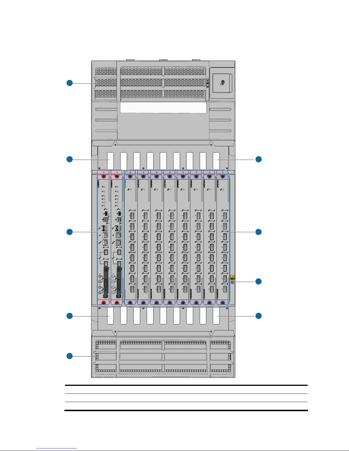
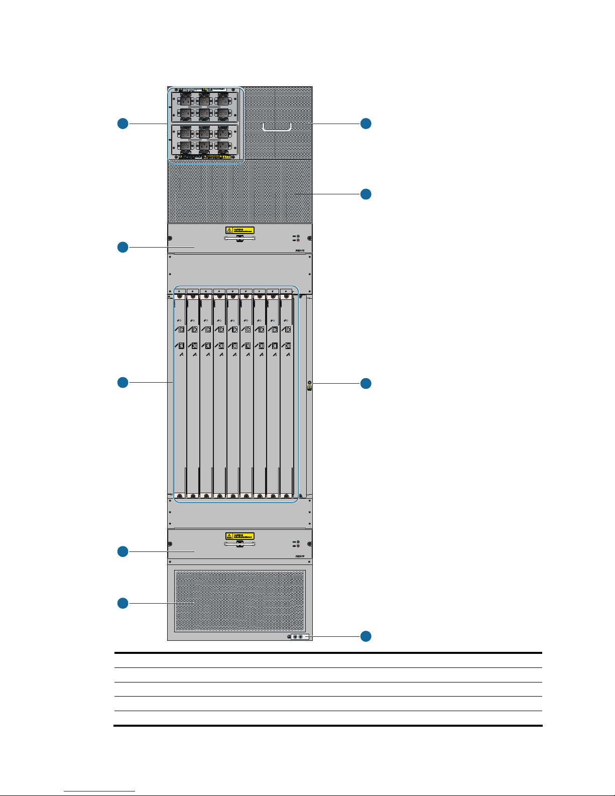
Figure 1 S12508 front view
1
2
3
4
5
2
4
6
7
(1) Power frame cover (2) Upper cabling rack (3) MPU slots (slots 0 and 1)
(4) Lower cabling rack (5) System air intake vents (6) ESD-preventive wrist strap port
(7) Line card slots (slots 2 to 9)
Page 13
3
NOTE:
The power frame cover protects the power module air filter and the power frame slot. See “Power supply
syst
em.”
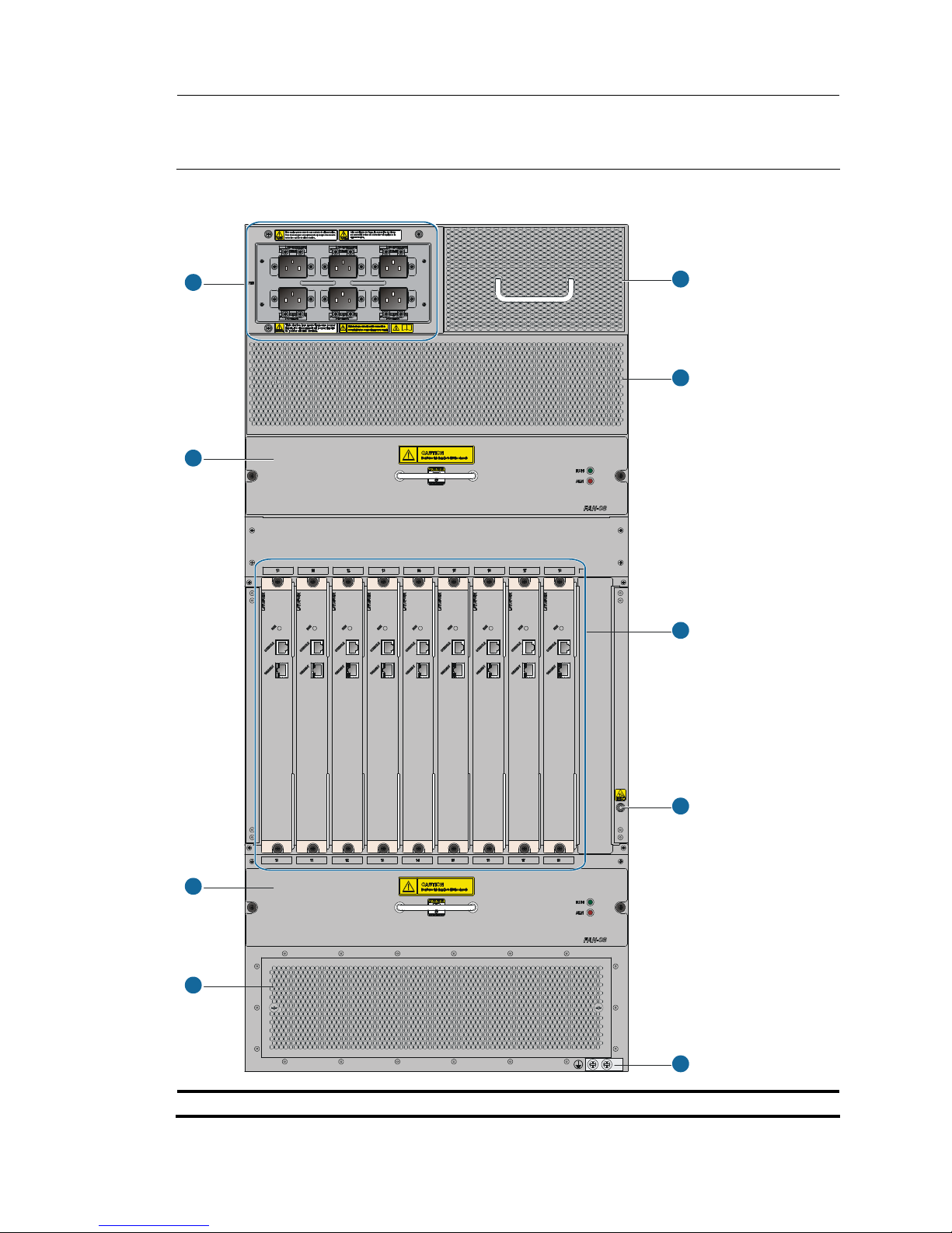
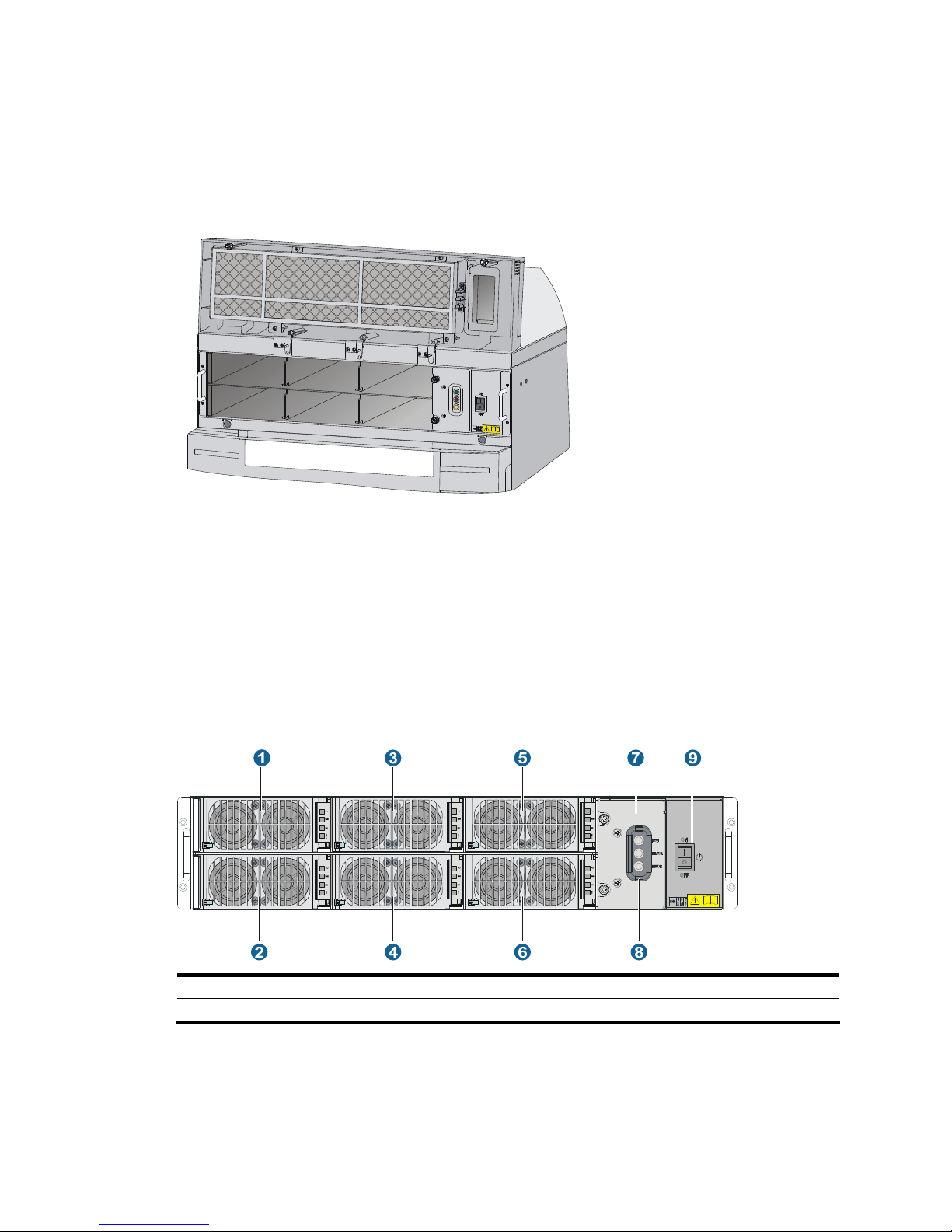
Figure 2 S12508 rear view
1
2
3
4
5
6
8
7
9
(1) Power entry module (PEM) (2) Upper fan tray
Page 14

4
(3) Lower fan tray (4) Ventilation panel
(5) Grounding screw (6) ESD-preventive wrist strap port
(7) Switching fabric module slots (slots 10 to 18) (8) System air exhaust vents
(9) Power air exhaust vents
The S12508 chassis has the following slots and components:
• Two MPU slots and eight line card slots at the front, and nine switching fabric module slots at the
rear.
• One power frame, at the top of the chassis, can accommodate up to six power modules.
• Two horizontally oriented fan trays at the rear of the chassis. For the ventilation inside the chassis,
see Figure 7.
Page 15
5
S12518 chassis views
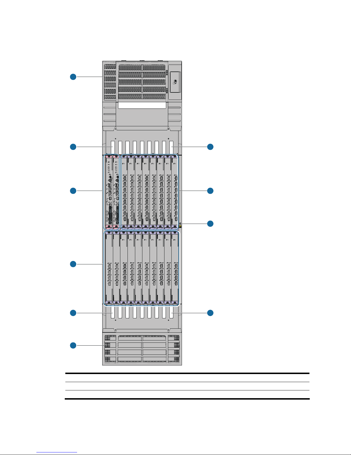
Figure 3 Front view of the S12518
1
22
3
55
7
6
4
4
(1) Power frame cover (2) Upper cabling rack (3) MPU slots (slots 0 and 1)
(4) Line card slots (slots 2 to 19) (5) Lower cabling rack (6) System air intake vents
(7) ESD-preventive wrist strap port
Page 16
6
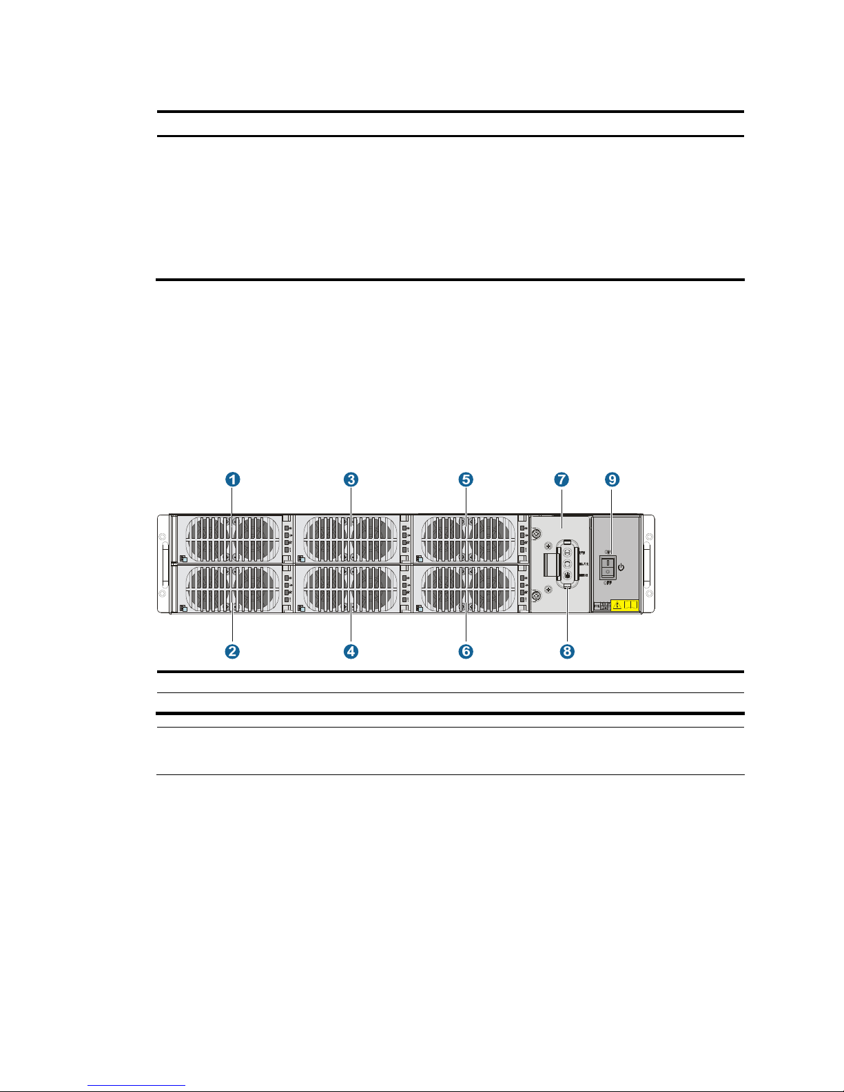
Figure 4 S12518 rear view
1
2
3
4
5
6
7
8
9
(1) Power entry module (PEM) (2) Upper fan tray
(3) Switching fabric module slots (slots 20 to 28) (4) Lower fan tray
(5) Ventilation panel (6) Grounding screw
(7) ESD-preventive wrist strap port (8) System air exhaust vents
(9) Power air exhaust vents
Page 17

7
The S12518 chassis has the following slots and components:
• Two MPU slots and 18 line card slots at the front, and nine switching fabric module slots at the rear.
• Two power frames at the top, and each power frame can accommodate up to six power modules.
• Two horizontally oriented fan trays at the rear. For the ventilation inside the chassis, see Figure 7.
Backplane
The backplane of an S12500 switch is located inside the chassis. It provides high-speed data switching
between switching fabric modules and line cards, and exchanges management and control signals
between MPUs and line cards/switching fabric modules. The backplane provides the following
capabilities:
• Provides communication channels for signal exchange between cards.
• Supports hot-swapping of cards.
• Identifies card type.
• Supplies power to MPUs, line cards, switching fabric modules, fan trays, and power modules when
connected to the power frame.
• Provides monitoring channels to monitor power module status.
Fan tray
A fan tray contains fan units. The dimension of each fan unit is 120 × 120 × 38 mm (4.72 × 4.72 ×1.50
in).
Both the S12508 and the S12518 use an upper fan tray at the top and a lower fan tray at the bottom.
Each fan tray comprises 12 fan units and one fan monitoring board.
S12500 fan trays provide the following functions:
• Effective heat dissipation and single-point of failure protection.
• Status monitoring, including fan rotation speed monitoring and fault alarming.
• Fan speed can be controlled by the MPU or automatically adjusted based on temperature. The
S12508 and S12518 have four groups of fans. Speed adjustment is done on a per-group basis to
decrease noise and improve energy efficiency.
• Each fan tray has two LEDs on the front panel to show its operating status.
• Hot swappable. The fans receive DC power from the backplane, and are hot swappable.
CAUTION:
The S12508 and S12518 use different fan trays, and do not support the intermixing of fan trays.
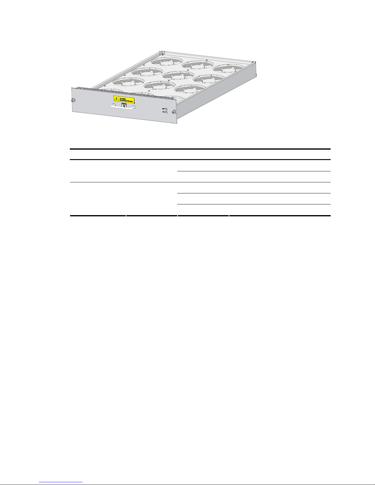
Figure 5 shows the S12508 fan tray. The physical view of the S12518 fan tray is similar.
Page 18
8
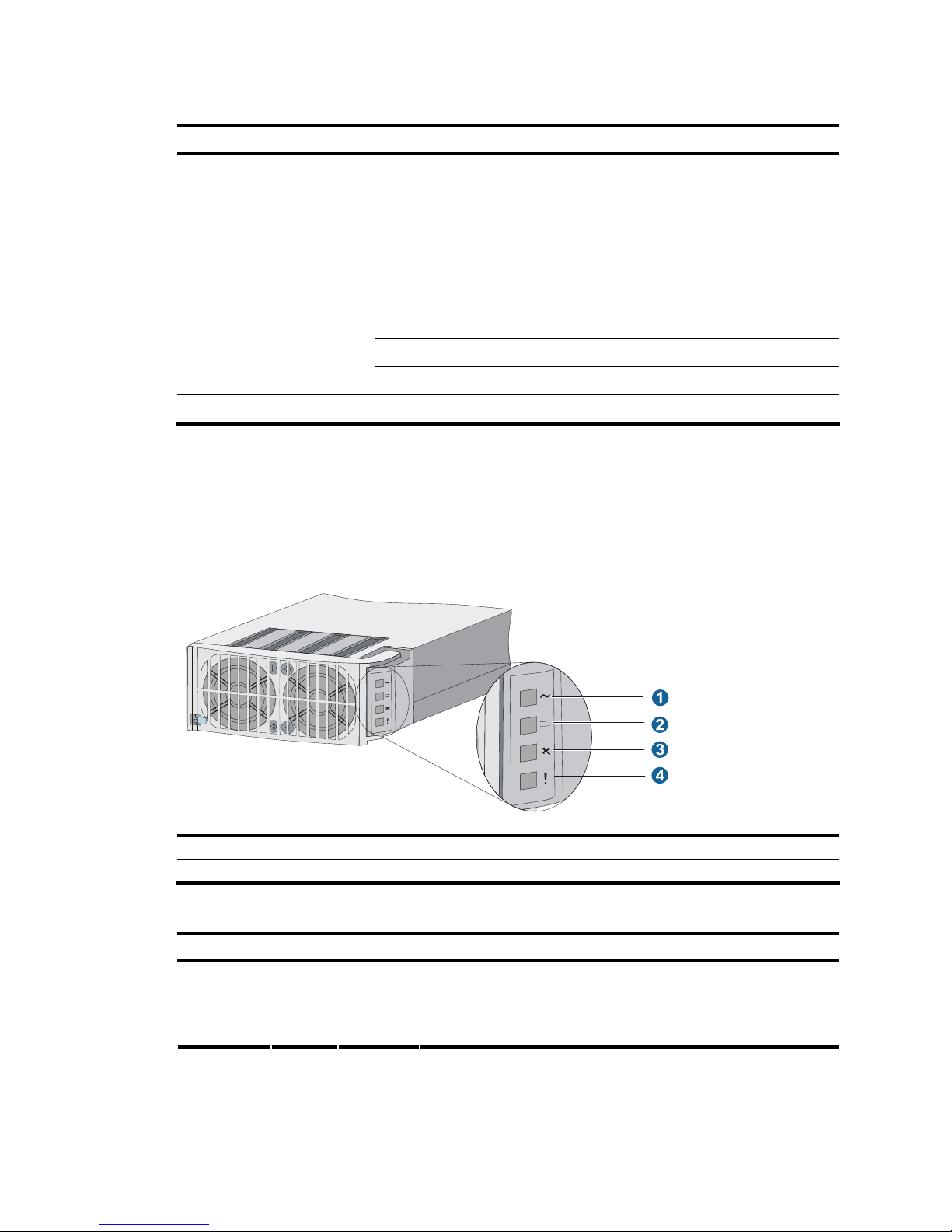
Figure 5 S12508 fan tray
Table 2 Fan LED description
LED Color Status Description
Off
The fan tray has failed.
RUN Green
Flashing
The fan tray is operating properly.
Off
The fan tray is in a normal state.
Flashing
The fan tray is faulty.
ALM Red
On The fan tray is faulty.
Figure 6 and Figure 7 show the ventilation inside the chassis of the S12508 and S12518.
Page 19
9
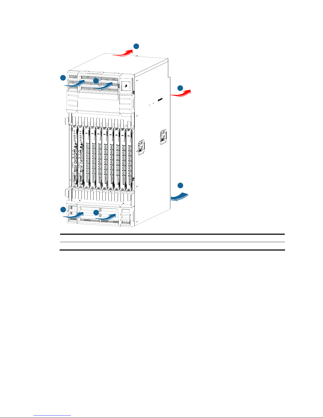
Figure 6 Ventilation inside an S12508 chassis
1
1
2
3
3
4
1
(1) System air intake direction (2) System air exhaust direction
(3) Power module air intake direction (4) Power module air exhaust direction
Page 20
10
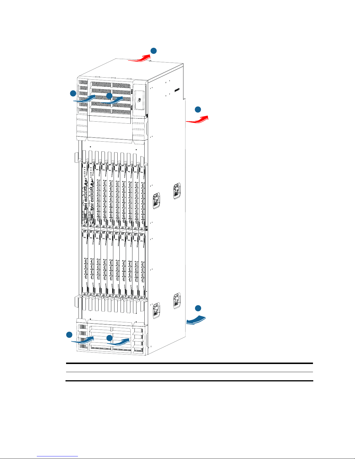
Figure 7 Ventilation inside an S12518 chassis
1
1
1
3
3
2
4
(1) System air intake direction (2) System air exhaust direction
(3) Power module air intake direction (4) Power module air exhaust direction
Page 21
11
Power supply system
The S12500 Routing Switch Series provides both AC powered chassis and DC powered chassis. You can
select power module and the number of power modules as needed.
Figure 8 Power frame appearance (without any power module)
AC power supply
The AC-powered chassis of the S12500 Routing Switch Series use the PSE9000-A1 AC power supply
system, which comprises AC power frames, AC power modules, power monitoring modules, and power
entry modules (PEMs).
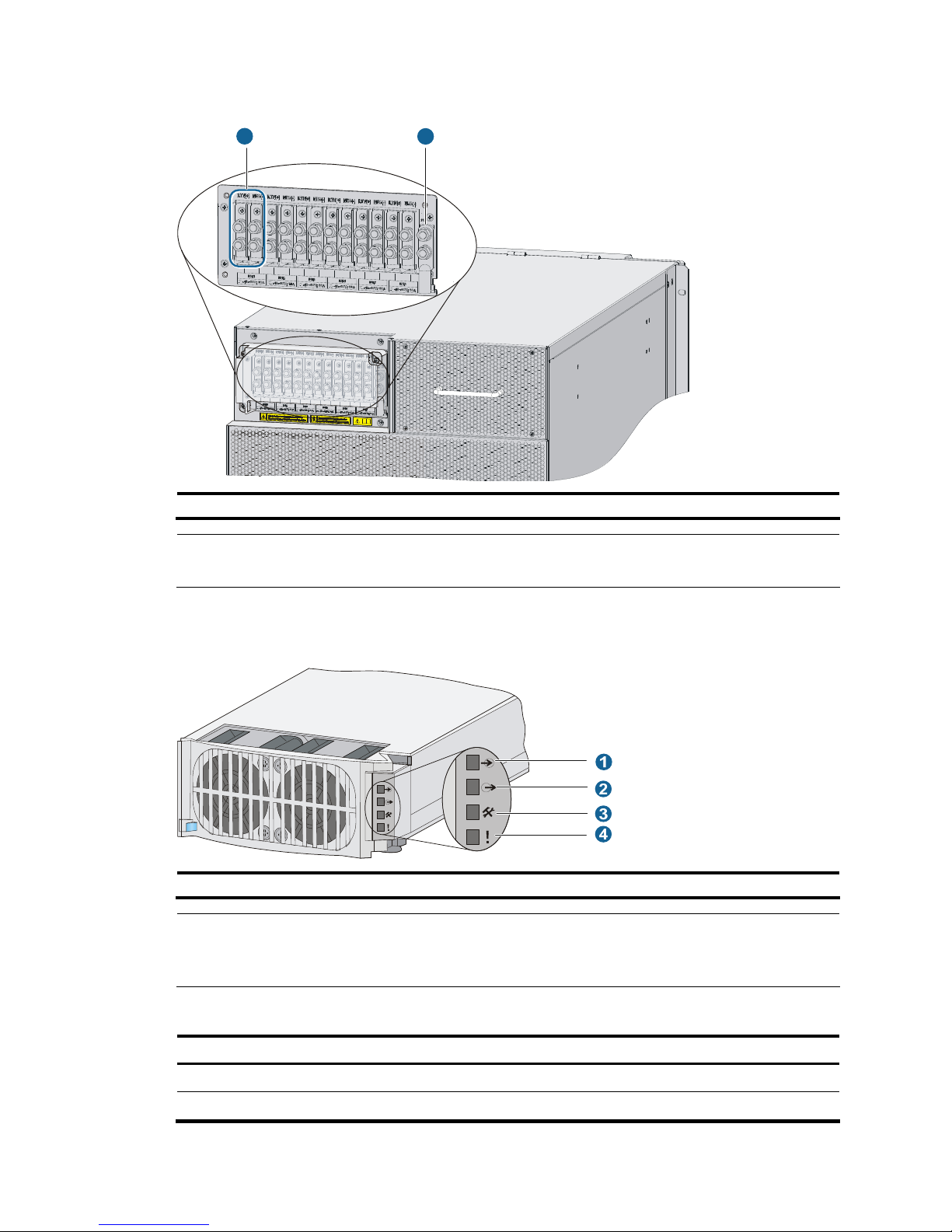
AC power frame
Each AC power frame can have one power monitoring module and up to six AC power modules.
Figure 9 Front view of an AC power frame
(1) to (6) AC power modules (the serial numbers are identical to the slot numbers)
(7) Power monitoring module (8) Power monitoring module LED (9) Power frame switch
Page 22
12
Table 3 Description of the LEDs on the power monitoring module
LED Color Status Description
On
The power monitoring module is working properly.
RUN Green
Off
The power monitoring module is faulty.
On
• At least one power module is faulty.
• All power modules have been removed from the power
frame.
• The switch of the power frame is off.
• Power modules are in position, but no AC power supply
is provided.
Flashing A power module is being inserted or removed.
MAJOR Red
Off
The power modules are working properly.
MINOR Yellow Off Reserved
AC power module
• The AC power modules are hot-swappable.
• The power module fans draw in fresh air from the front and exhaust warm air out of the rear.
• Multiple AC power modules work in N+1 or N+M redundancy and support load balancing.
Figure 10 AC power module
(1) Power input LED (2) Power output LED (3) Over-temperature alarm LED
(4) Power module fault LED
Table 4 AC power module LED description
LED Color Status Description
On
Power is being correctly input.
Off
No power is being input.
Input Green
Flashing Input power exceeds the threshold.
Page 23
13
LED Color Status Description
On Power is being correctly output.
Off No power is being output.
Output Green
Flashing The power output is overloaded.
On
The AC power module is experiencing an over-temperature
condition.
Service Yellow
Off
The AC power module is operating properly.
On The AC power module is faulty.
Fault Red
Off The AC power module is operating properly.
Table 5 AC power module specifications
Item Description
Rated input voltage range
100 VAC to 120 VAC/200 VAC to 240 VAC; 50 Hz or 60 Hz
Max input voltage range
90 VAC to 264 VAC; 47 Hz to 63 Hz
Max input current 13.3 A
Max output power
2000 W at 200 VAC to 240 VAC input
1200 W at 100 VAC to 120 VAC input
Power monitoring module
The power monitoring module (callout 7 in Figure 9) monitors the alarm status, in-position status, and
operating status of the power modules in real time. It is located between the power module slot area and
the power switch.
PEM
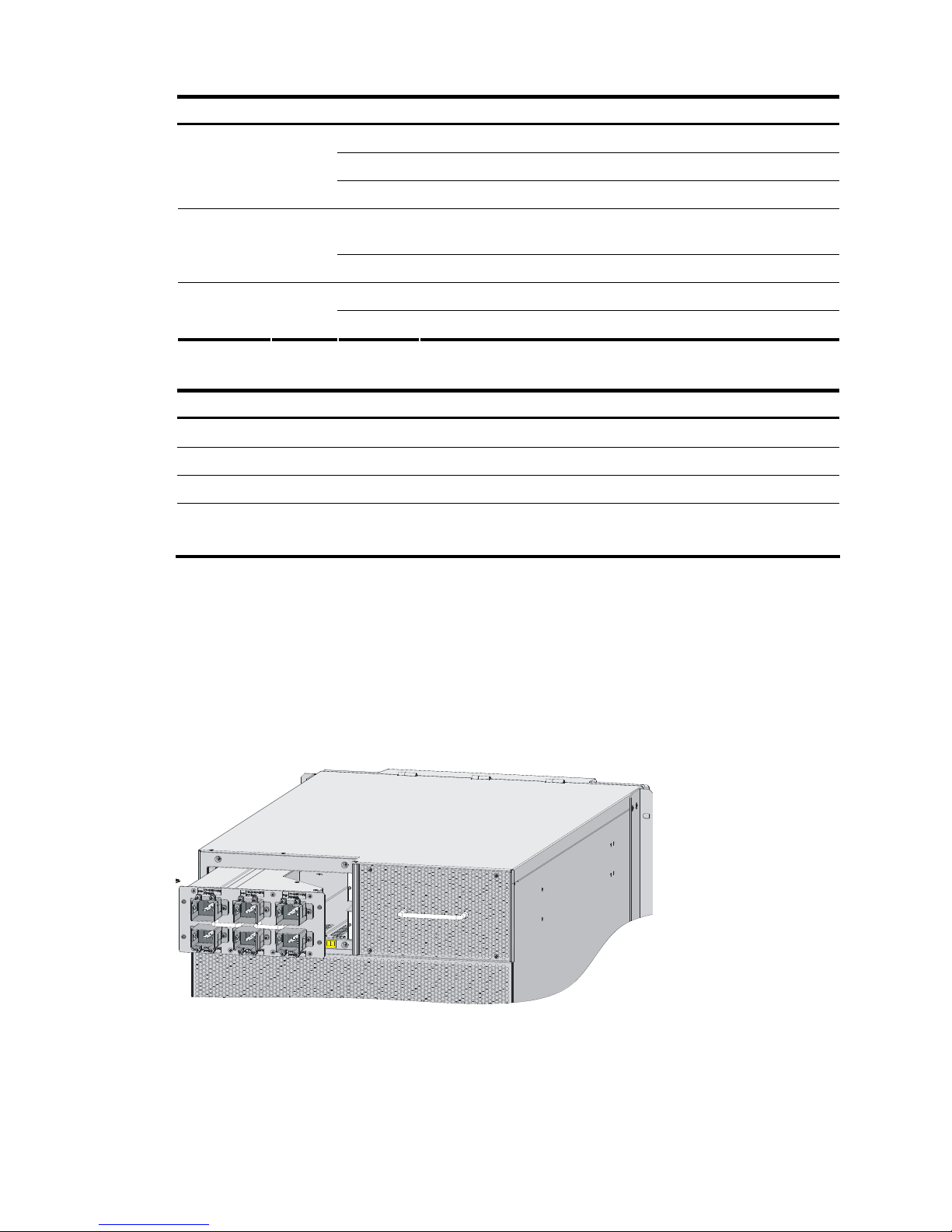
The PEM (see Figure 11) provides power to the power modules.
Figure 11 PEM location
Page 24
14
Table 6 PEM description
PEM Description Max number of power modules
LSTM2PEMC6 (PEM-C20)
Applied to the 110 V or 220 V
single-phase three-wire AC power
supply system
One PEM provides six standalone
C20 (16A) sockets numbered in
two rows: 1, 3, and 5 in the top
row, and 2, 4, and 6 in the bottom
row, from left to right.
6 (each C20 socket for one power module)
DC power supply
The DC-powered chassis of the S12500 Routing Switch Series use the PSE9000-D DC power supply
system, which comprises DC power frames, DC power modules, and power monitoring modules.
DC power frame
Each DC power frame can have one power monitoring module and up to six DC power modules.
Figure 12 Front view of a DC power frame
(1) to (6) DC power modules
(7) Power monitoring module (8) Power monitoring module LEDs (9) Power frame switch
NOTE:
Table 2 descri
bes the LED behaviors of the power monitoring module.
A DC power frame has six pairs of wire posts corresponding to power modules 1 to 6, and one
grounding post. The external DC power system supplies power through the six pair of wire posts.
Page 25
15
Figure 13 DC power frame rear view
1 2
(1) A pair of wire posts (2) Grounding post
NOTE:
The DC power frame has a cover to protect the wire posts and grounding post.
DC power module
Figure 14 DC power module
(1) Power input LED (2) Power output LED (3) Over-temperature alarm LED (4) Power fault LED
NOTE:
A DC power module has the same LED behaviors as an AC power module. For more information, see
Table 7.
Table 7 DC power module specifications
Item Description
Rated input voltage range –48 VDC to –60 VDC
Max input voltage range –42 VDC to –72 VDC
Page 26

16
Item Description
Startup voltage range –44 VDC to –72 VDC
Max input current 60 A
Max output power 1800 W
Power monitoring module
The power monitoring module is vertically installed between the power module slot area and the power
switch. It monitors the alarm status, in-position status, and operating status of the power modules in real
time.
Page 27

17
Preparing for installation
Safety recommendations
To avoid any equipment damage or bodily injury caused by improper use, read the following safety
recommendations before installation. Note that the recommendations do not cover every possible
hazardous condition.
General safety recommendations
• Take adequate safety measures to avoid injury and switch damage. For example, wear an
ESD-preventive wrist strap.
• Make sure that the ground is dry and flat and anti-slip measures are in place.
• Keep the chassis clean and dust-free.
• Do not place the switch on a moist area and avoid liquid surrounding the switch.
• Keep the chassis and installation tools away from walk areas.
• Move the switch and heavy components (such as the power supplies or chassis) with other people
rather than doing that alone.
Electricity safety
• Clear the work area of possible hazards, such as ungrounded power extension cables, missing
safety grounds, and wet floors.
• Locate the emergency power-off switch in the room before installation. Shut the power off at once in
case accident occurs.
• Unplug all the external cables (including power cables) before moving the chassis.
• Do not work alone when the switch has power.
• Always check that the power has been disconnected.
ESD prevention
CAUTION:
To prevent the electronic components from being damaged by the electrostatic discharge (ESD), you
should not only take ESD measures where the switch is located, but also take the following precautions:
• Always wear an ESD-preventive wrist strap when installing components, especially the electronic printed
circuit boards.
• Hold a PCB by its edges. Do not touch any electronic components or printed circuit.
• Check the resistance of the ESD-preventive wrist strap for safety. The resistance reading should be in the
range of 1 to 10 megohm (Mohm) between human body and the ground.
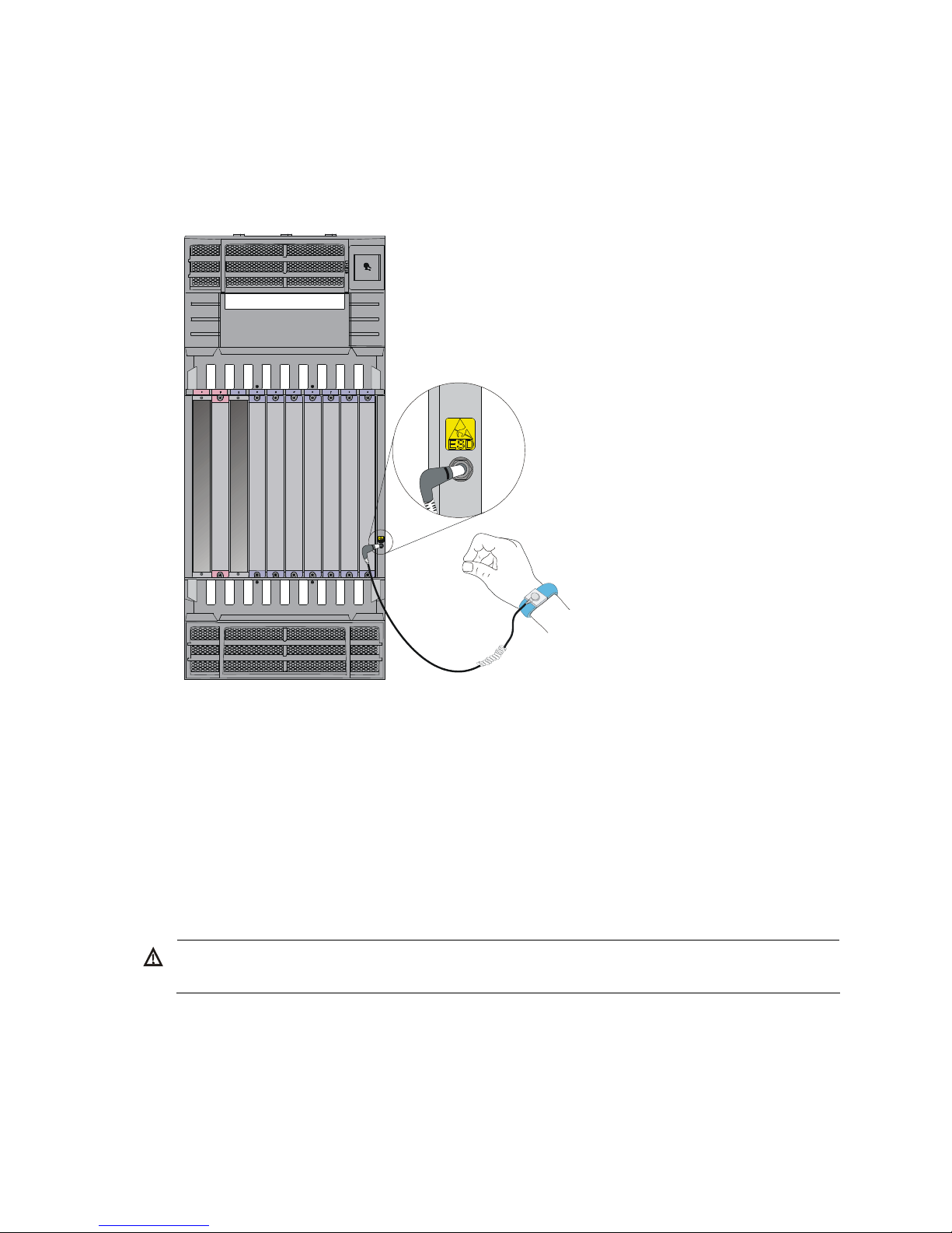
To use the ESD-preventive wrist strap:
1. Wear the wrist strap on your wrist.
Page 28
18
2. Lock the wrist strap tight around your wrist to keep good contact with the skin.
3. Insert the ESD-preventive wrist strap into the specially designed hole on the switch chassis or attach
it to the grounding screw of the chassis with the alligator clips.
4. Make sure that the ESD-preventive wrist strap is well grounded.
Figure 15 Use an ESD-preventive wrist strap
Switch moving
When you move an H3C S12500 switch, note the following guidelines:
• Remove all the external cables (including the power cables) before moving the chassis.
• For personal safety, have several persons to move the switch carefully.
• When moving the switch, hold the handles at both sides of the chassis. Do not hold the plastic panel
of the chassis, the handle of the fan tray, the handle of the back cover of the chassis, or the air vents
of chassis. Any attempt to carry the switch with these parts may cause equipment damage or even
bodily injury.
WARNING!
For personal safety, at least four people are required to move an S12518 switch.
Laser safety
The H3C S12500 switches are Class 1 laser devices.
Page 29

19
WARNING!
Do not stare into any fiber port when the switch has power. The laser li
g
ht emitted from the optical fiber
may hurt your eyes.
Examining the installation site
The H3C S12500 Routing Switch Series can only be used indoors. To ensure that the switch works
properly and to prolong its service lifetime, the installation site must meet the following requirements:
Weight support
Evaluate the floor loading as compared to the actual weight of the switch and its accessories (such as
cabinet, chassis, cards, and power supply units), and make sure that the floor can support the weight of
the cabinet and the switch chassis.
TIP:
When you evaluate the floor loading, consider router
capacity expansion (for example, installing a ne
w
card) in the future.
Temperature
To ensure the normal operation of the switch, make sure that the room temperature meets the
requirements described in Table 8.
Table 8 Temperature r
equirements
Temperature Range
Operating temperature
Long term: 0°C to 40°C (32°F to 104°F)
Two hours: –10°C to +50°C (14°F to 122°F) (no more than 96
hours of continuous operation in less than 15 days in one year)
Storage temperature –40°C to +70°C (–40°F to +158°F)
CAUTION:
If condensation appears on the switch when you move it to a high-temperature environment, dry the switch
before powering it on to avoid short circuits.
Humidity
Maintain appropriate humidity in your equipment room, as described in Table 9.
Table 9 Humidity requirements
Humidity Range
Operating humidity (noncondensing) 5% to 95%
Storage humidity (noncondensing) 5% to 95%
Page 30

20
Lasting high relative humidity can cause poor insulation, electricity creepage, mechanical property
change of materials, and metal corrosion. Lasting low relative humidity can cause washer contraction
and ESD and bring problems including loose captive screws and circuit failure.
Cleanness
Dust buildup on the chassis may result in electrostatic adsorption, which causes poor contact of metal
components and contact points, especially when indoor relative humidity is low. In the worst case,
electrostatic adsorption can cause communication failure.
Table 10 Dust concentration limit in the equipment room
Substance Concentration limit (particles/cu m)
Dust particles ≤ 3 x 10⁴ (no visible dust on the tabletop over three days)
NOTE:
Dust particle diameter ≥ 5 μm
The equipment room must also meet strict limits on salts, acids, and sulfides to eliminate corrosion and
premature aging of components, as shown in Table 11.
Table 11 Harmful gas li
mits in the equipment room
Gas Average (mg/m
3
) Max. (mg/m3)
SO2 0.3 1.0
H2S 0.1 0.5
NO2 0.004 0.15
NH
3
1.0 3
Cl
2
0.1 0.3
EMI
All electromagnetic interference (EMI) sources, from outside or inside of the switch and application
system, adversely affect the switch in a conduction pattern of capacitance coupling, inductance coupling,
electromagnetic wave radiation, or common impedance (including the grounding system) coupling. To
prevent EMI, take the following actions:
• If AC power is used, use a single-phase three-wire power receptacle with protection earth (PE) to
filter interference from the power grid.
• Keep the switch far away from radio transmitting stations, radar stations, and high-frequency
devices.
• Use electromagnetic shielding, for example, shielded interface cables, when necessary.
• Route interface cables only indoors to prevent signal ports from getting damaged by overvoltage or
overcurrent caused by lightning strikes.
Grounding
Using a good grounding system to protect your switch against lightning shocks, interferences, and ESD
is essential to the operating reliability of your switch.
Page 31

21
Make sure that the resistance between the chassis and the ground is less than 1 ohm.
Power supply
Perform the following steps to satisfy the power supply requirements of the S12500 Routing Switch Series:
1. Calculate the system power consumption.
2. Select power supplies according to the system power consumption and power supply mode.
To ensure normal operation of the switch, make sure the maximum output power of the power
supplies is greater than the system power consumption of the switch (reserve certain power for
redundancy). After determining the system power consumption and power supply mode (AC or
DC power supply), you can select power supplies as needed.
3. Check that the power source on the installation site satisfies the power input of the power supplies.
Make sure the power source of the installation site is steady and can satisfy the input requirements
of the power supplies and parameters such as rated voltage.
NOTE:
For the power consumption and power module
specifications of the switch, see the chapter “Appendix
A
Technical specifications.”
Space
• For moving the switch and servicing the modules, make sure that the width of the aisle in the
equipment room is at least 0.8 m (2.62 ft).
• To install the switch in a rack, make sure the headroom in the equipment room is no less than 3 m
(9.84 ft).
• For adequate ventilation and ease of maintenance, do not place the switch close to the wall, and
make sure the front and rear clearances are at least 0.8 m (2.62 ft).
Rack-mounting
To mount the switch in a rack, adhere to the following requirements:
• Use a four-post 19 inch standard rack.
• The distance between the left and right rack posts is 465 mm (18.31 in).
Page 32

22
Figure 16 Rack width
• Make sure that the available space between the front rack post and the outer edge of the front rack
door is greater than 180 mm (7.09 in) and the depth of the rack (distance between the front and
back doors) is greater than 800 mm (31.50 in).
Figure 17 Rack depth
>
1
8
0
m
m
>
1
5
5
m
m
>
8
0
0
m
m
• The rack is available with standard slide rails (or rack shelves), cage nuts, and screws.
Page 33

23
• The slide rails (or rack shelves) can support the weight of the switch chassis and its accessories.
• The rack can be well grounded.
• The rack has good ventilation system, and the porosity of the front and back doors is greater than
50%.
Installation tools
Accessories supplied by the switch
Item Quantity Purpose
Console cable 1
Connecting the console port and
the configuration terminal for
switch login
Grounding cable 1 Grounding the switch
Mounting brackets 1 pair Fixing the switch to the rack
M4*8 screw 1 set
Fixing the mounting brackets to the
switch
M6*12 screw 1 set
M6 cage nut 1 set
Fixing the switch to the rack
Air deflector 1
Installed at the rear of the switch to
block air from entering the chassis
(optional)
ESD-preventive wrist strap 2 ESD-prevention
NOTE:
The number of screws and nuts supplied with the switch depends on those shipped from the factory.
User-supplied tools and equipment
• Mechanical lift
• Phillips screwdriver P1 – 100 mm, P2 – 150 mm and P3 – 250 mm
• Flat screwdriver P4 – 75 mm
• Marker
• Tape
• Diagonal pliers, wire-stripping pliers, and wire clippers
• Socket wrench
• Cables such as network cables and fiber cables
• Meters and equipment, such as hub and multimeter
• Configuration terminal, such as PC
NOTE:
The rack accessories and installation tools are not included in this section. The accessories and installation
tools may vary depending on the rack model. For more information, see the installation guide of the
corresponding rack.
Page 34

24
Installing the switch
WARNING!
To avoid bodily injury, do not touch any wire, terminal, or part marked with a high-volta
g
e hazard sign.
Figure 18 Hardware installation flow
Start
Install the switch to a rack
Ground the switch
End
Install fan traysInstall power supplies
Connect the power cords
Verify the installation
Determine the
installation site
Install the switch to a workbench
Install cards
Check before installation
Check the following before installing an H3C S12500 switch:
• Make sure that you have read “Preparing for Installation” carefully and the installation site meets all
the requirements.
• Using the packing list supplied with your switch, inspect the switch to be sure that you have all the
items listed in the packing list, and verify that the switch was not damaged during shipment. If
anything is damaged or missing, contact the sales agent or customer representative immediately.
• For regulatory compliance and safety information, see “Regulatory Compliance and Safety
Information”.
Page 35

25
Installing the switch in a rack
Installation preparation
Confirm the following preparations before starting installation:
• The rack is sturdy and securely grounded.
• There is sufficient clearance of 0.8 m (2.62 ft) around the rack for heat dissipation and installation.
• There is no debris inside or around the rack.
CAUTION:
When moving the switch, hold the handles at both sides of the chassis. Do not hold the plastic panel of the
chassis, the handle of the fan tray, the handle of the back cover of the chassis, or the air vents of chassis.
Any attempt to carry the switch with these parts may cause equipment damage or even bodily injury.
Installing slide rails and cage nuts to the rack
Installing slide rails
Before installing the switch to the rack, install slide rails to the rack. If the rack has slide rails, skip this
section.
NOTE:
• Before installing the slide rails, check that the slide rails can support the weight of the switch. For the
weights of the S12500 Routing Switch Series, see the chapter “Appendix A Technical specifications.”
• Besides slide rails, you can use a rack shelf to support the switch. This document describes how to install
slide rails only.
• Slide rails or rack shelves are not provided with the switch. Prepare them yourself, or order them from
H3C.
The following uses a 19-inch rack as an example to describe the installation procedures. The height of the
front panel of the rack is a measurement of one rack unit (RU) (44.45 mm, or 1.75 in). As shown in callout
2 in Figure 19, e
ach 1 RU has three holes with center-to-center spacing between the holes of 15.87 mm
(0.63 in), 15.87 mm (0.63 in), and 12.70 mm (0.5 in). When installing the slide rails, make sure the
bottom edge of the slide rail aligns with the middle of the narrower metal area between holes.
To install the slide rails:
1. Mark the position of the slide rails on the rack.
2. Align the screw holes on the two sides of the slide rails with the corresponding holes on the rack,
and then fasten the screws.
3. Install the other slide rail in the same way. Keep the two slide rails at the same height so that the
switch can be placed evenly.
Page 36

26
Figure 19 Install the slide rails
1
1
2
(1) Middle of the narrower metal area between holes (2) 1 RU
NOTE:
• The appearance and installation methods of slide rails depend on the slide rail types.
• To ensure stability of the rack, install the slide rails to the lowest possible position when installin
g
a single
switch on the rack. To install multiple switches on the rack, mount the heaviest switch at the bottom of the
rack.
Installing cage nuts
Before mounting the chassis to the rack, install cage nuts to the front square-holed brackets of the rack.
To install cage nuts to the rack:
1. Align the mounting bracket with the left rack post, making sure that the bottom edge and the slide
rail are level. Mark the positions of the cage nuts on the rack post according to the installation
holes on the mounting bracket (each installation hole on the mounting bracket corresponds to one
cage nut).
2. Insert one edge of a cage nut into the hole.
3. Compress the other edge of the cage nut to push the cage nut fully into the hole.
4. Repeat steps 3 and 4 to install cage nuts to all the marked positions on the right rack post.
Page 37

27
Figure 20 Install the cage nuts
NOTE:
When preparin
g
for installation, make sure that the total height of the switches to be installed is no higher
than the height of the rack, and reserve enough clearance for cable routing.
Installing the mounting brackets
Attach the mounting brackets onto the left and right sides of the switch.
Page 38

28
Figure 21 Install the mounting brackets
Installing an air deflector (optional)
An air deflector is shipped with the S12500 switches. You can install the air deflector at the rear of the
chassis (where a ventilation panel is located) to block the airflow from entering the rear of the chassis.
Install an air deflector where switches adopt front to rear airflow.
To install an air deflector:
1. Loosen the captive screws on the ventilation panel to remove it.
2. Install the air deflector, and fasten the captive screws on the air deflector.
Page 39

29
Figure 22 Install an air deflector
Installing a chassis air filter (optional)
Chassis air filters are installed at the air intake vents to prevent dust from entering the chassis. Chassis air
filters of the S12500 Routing Switch Series are optional. You can order them as needed.
If you have ordered chassis air filters, H3C recommends you to install the air filters before mounting the
switch to the rack.
• S12508: A chassis air filter is available at both front and rear of the switch. For the installation
procedures, see “Installing an air filter on an S12508.”
• S12518: The air filter is located at the rear of the chassis. For the installation procedures, see
“Installing an air filter on an S12518.”
Installing an air filter on an S12508
To install the front air filter on an S12508:
1. Holding the notches of the front plastic panel at the bottom part of the chassis, and gently pull the
plastic panel out.
2. Unpack the air filter and attach it to rear of the plastic panel, making sure the installation holes on
the air filter align with the screw holes on the plastic panel. Then fix the air filter to the plastic panel
with screws.
3. Fix the plastic panel back to the chassis.
Page 40

30
Figure 23 Install the front air filter
1
2
3
To install the rear air filter on an S12508:
1. Loosen the captive screws on the ventilation panel and remove it.
2. Unpack the air filter and attach it to where the ventilation panel was located, and then fasten the
captive screws on the air filter.
Figure 24 Install the rear air filter
(1) Ventilation panel (2) Rear air filter
Installing an air filter on an S12518
To install an air filter on an S12518:
1. Use a Phillips screwdriver to loosen the screws at both sides of the plastic panel and remove the
panel.
2. Insert the air filter into the rear of the chassis along the slide rails, and then fasten the screws at both
sides of the air filter.
Page 41

31
Figure 25 Install an air filter
Mounting the switch in the rack
NOTE:
• Make sure that you have installed slide rails or a rack shelf on the rack for supporting the switch. The
slide rails or rack shelf should be sturdy enough to support the weight of the switch chassis and all
accessories.
• To maximize the stability of the rack, mount the switch at the lowest possible position.
To mount the switch in the rack:
1. Use several persons to place the switch on the slide rails or rack shelf and slide the switch into the
rack until the mounting brackets on the switch touch the front rack posts.
2. Fix the mounting brackets to the rack posts with mounting screws. See Figure 26.
Figure 26 Install the switch in a standard 19-inch rack
Page 42

32
NOTE:
If the screw holes on the mounting brackets cannot align with the cage nuts on the rack, check that the
bottom edge of the slide rail aligns with the middle of the narrowest metal area between holes and that the
cage nuts are installed in the correct holes.
Verifying the installation
After the installation is completed, check the installation against the following checklist. Make sure that
all check results are positive.
Table 12 Installation checklist
Result
Item
Yes No
Remarks
The mounting brackets are firmly fixed onto the switch.
The switch is sturdy and installed in the right position.
The mounting brackets on the switch are firmly fixed onto the rack.
Installing the switch on a workbench
You can install the switch on a clean, sturdy workbench or on the floor.
Installation preparation
Before placing the switch on a workbench or on the floor, confirm the following preparations:
• The workbench or floor is sturdy enough to support the weight of the chassis and its accessories.
• The workbench or floor is reliably grounded.
• Whether an air deflector or air filter is needed. To install them, see “Installing an air deflector
(opti
onal)” and “Installing a chassis air filter (optional).”
Installation procedures
CAUTION:
Allow 0.8 m (2.62 ft) of clearance around the switch for heat dissipation.
To install the switch:
1. Hold the two sides of the switch and steadily move the switch to the workbench.
2. Lift the switch a little higher than the workbench and put it on the workbench.
3. Install the mounting brackets on the switch and fasten the screws, as shown in Figure 27 (optional).
NOTE:
Each circled area in Figure 27 shows two rows of installation holes. You can select either row of a
circled
area to install the mounting brackets.
Page 43

33
Figure 27 Install the mounting brackets
1
2
(1) Mounting bracket installation holes (2) Mounting bracket
4. Fix the switch to the workbench or ground with L-shaped brackets. See Figure 28.
Figure 28 Install L-shaped brackets
(1) L-shaped bracket (2) Wall anchor (3) Mounting screw
Page 44

34
Grounding the switch
WARNING!
For the safety of operators and equipment, securely ground the switch. Make sure that the resistance
reading between the switch chassis and the ground is less than 1 ohm.
Most racks are equipped with a grounding strip. You can connect the yellow-green grounding cable of
the switch to the grounding strip.
NOTE:
Use the supplied grounding cable (CAT 6 cable with dual-hole OT terminals).
To connect the grounding cable:
1. Remove the two grounding screws from the switch chassis.
2. Use the grounding screws to attach one end of the grounding cable to the chassis.
3. Connect the other end of the grounding cable to the grounding strip of the rack in the same way.
Figure 29 Connect the grounding cable
1
2
3
Page 45

35
If there is no grounding point on the rack, you can attach the grounding cable to a grounding strip. The
installation procedures are similar.
CAUTION:
Connect the grounding cable to the earthing system in the equipment room. Do not connect it to a
fire main
or lightning rod.
Installing the power system
The S12500 Routing Switch Series supports both AC and DC power module. You can select either AC or
DC power module as needed. For how to connect power cords, see “Connecting power cords.”
Installation preparation
To prepare for installation:
1. Put on an ESD-preventive wrist strap and make sure that it is properly grounded.
2. Remove the blank panel (if any) from the slot to be used.
3. Remove the power frame cover.
CAUTION:
• Hold a power entry module (PEM) or power module by the bottom when moving it. Never attempt to lif
t
a PEM or power module with its handle because the handle is not designed to support weight. Doing so
might result in bodily injury or damage to the module.
• When inserting or removing a power module, check that the switch is sturdy. To prevent bodily injury,
avoid tipping the switch chassis.
• When hot-plugging power modules, make sure that the insertion interval is no less than 30 seconds.
Installing a DC power module
To install a DC power module:
1. Rotate the power frame cover up with both hands.
2. Pull the clip at the bottom left corner of the power module to the left to open the power module
panel.
3. Insert the power module slowly into the slot until it is firmly seated in the slot.
4. Close the panel of the power module, press the clip to lock the power module in position, and close
the power frame cover.
Page 46

36
Figure 30 Install a power module
Installing an AC power module
To install an AC power module, follow these steps:
• Installing a PEM
• Installing an AC power module
Installing a PEM
To install a PEM:
1. Loosen the screws on the filler panel of the PEM slot with a Phillips screwdriver to remove the filler
panel.
2. Insert a PEM slowly along the slide rails until it touches the backplane connector.
3. Use the M3 screws supplied with the PEM to fix the PEM to the switch chassis, and fasten the
screws with a Phillips screwdriver.
Page 47

37
Figure 31 Install a PEM
NOTE:
Gently insert the PEM into the chassis to avoid damaging the connector at the end of the PEM.
Installing an AC power module
IMPORTANT:
• Make sure that the number of power modules is sufficient for the switch to operate properly.
• Each receptacle on the PEM corresponds to a power module slot. To enable an AC power module to
work, provide power module to the relevant receptacle.
• Distribute power modules in the upper and lower frames evenly on the S12518.
• The procedures for installing an AC power module are similar to installing a DC power module. For
more information, see “Installing a DC power module.”
Installing a fan tray
CAUTION:
• The fan trays are heavy. Do not try to move a fan tray by yourself.
• Hold a fan tray by the bottom when moving it. Never attempt to lift a fan tray with its handle because the
handle is not designed to support weight. Doing so might result in bodily injury or damage to the
module.
Page 48

38
Both the S12508 and S12518 have two fan trays. They are installed in the same way.
To install a fan tray:
1. Wear an ESD-preventive wrist strap and make sure that it is properly grounded.
2. Unpack the fan tray.
3. Remove the blank panel from the slot to be used.
4. Lift the fan tray and push it into the slot until it is firmly seated in the slot.
5. Fasten the captive screws on the front panel of the fan tray.
Figure 32 Install a fan tray
1
2
3
Installing a card
NOTE:
Install at least one MPU, one line card, and seven switching fabric modules on an S12508 or S12518.
The S12500 does not support intermixing of the MPU, line card, and switching fabric modules.
Use one of the following positions to install the card:
• Install MPUs, Ethernet interface cards, and OAA cards at the front of the switch chassis. Slot 0 and
Slot 1 are for MPUs and other slots (slots 2 to 9 for the S12508 and slots 2 to 19 for the S12518) are
for Ethernet interface cards and OAA cards.
Page 49

39
• Install switching fabric modules in the switching fabric module slots (slots 10 to 18 for the S12508
and slots 20 to 28 for the S12518) at the rear of the chassis.
CAUTION:
The LST1XP32REB1 and LST1XP32REC1 have three circled areas marked with HAND OPERATION ARE
A
(see Figure 33) on their print circuit board. You can touch these areas when holding the card. Touchin
g
any area outside these three areas might result in damage to the line card.
Figure 33 HAND OPERATION AREA sign on LST1XP32REB1/LST1XP32REC1
You can install MPUs, line cards, and switching fabric modules in a similar way. This section describes
how to install an MPU as an example.
Installation preparation
To prepare for installation:
1. Put on an ESD-preventive wrist strap and make sure that it is properly grounded.
2. Remove the blank panel (if any) from the slot to be used.
3. Unpack the card to be installed.
NOTE:
• Keep the removed the blank panel and protective box properly for future use.
• All the cards for the S12500 are hot-swappable.
Installation procedure
To install a card:
1. Remove the protective box before installing an MPU:
2. Put on an ESD-preventive wrist strap and then loosen the captive screws that fix the MPU to the
protective box with a Philips screwdriver.
3. Pull the MPU out of the protective box gently, as shown in Figure 34.
Page 50

40
Figure 34 Remove the protective box
4. Move the ejector levers of the MPU outwards, hold the MPU by the handle, and push the MPU into
the slot along slide rails slowly.
5. Push the ejector levers inward to ensure close contact between the MPU and the backplane.
6. Position the screws into the holes and fasten them with a screwdriver to fix the MPU.
Figure 35 Install an MPU
IMPORTANT:
• Fasten the screws of each card right after you insert it.
• To avoid damage to a card, do not use excessive force when installing and removing the card.
Page 51

41
Connecting power cords
Prerequisites
Follow these guidelines before connecting power cords:
• For lightning protection, the AC power should be led through an external lightning device into
S12500 Routing Switch Series. For more information, see the chapter “Appendix D Lightning
protection.”
• Make sure the power switch on the power frame is in the OFF position.
• For personal and switch safety, do not connect the power cords with the power. Power off the
grounding strip, connect the power cords, power on the grounding strip, and then power on the
switch.
Connecting an AC power cord
Each socket on a PEM (LSTM2PEMC6) corresponds to a power module slot. Sockets numbered 1 through
6 provide power module for the power modules in slots 1 through 6, respectively. If slot 1 is installed with
a power module, the number 1 receptacle on the PEM must be connected to a power source with an AC
power cord to make the power module operate properly.
CAUTION:
Typically 10 A busbars are available in the equipment room but the PEM on the S12500 (LSTM2PEMC6)
requires a 16 A power cord (AC), so you need to use a 16 A busbar, and ensure that the AC power
module system can provide enough power. For AC power cords used in different countries or regions, see
the chapter “Appendix A Technical specifications.”
To connect power cords:
1. Remove the strain-relief screws of the power cord retention clip, and remove the retention clip.
2. Insert the connector of the AC power cord into the PEM receptacle.
3. Install the retention clip to the connector and fasten the screws to lock the power connector.
4. Connect the other end of the AC power cord to the power source.
Page 52

42
Figure 36 Connect the AC power cord
Connecting a DC power cord
Six pairs of wiring terminals (marked PSR1 through PSR6) are available on the DC grounding strip of the
S12500 switches. The wiring terminals correspond to the power modules 1 through 6, respectively. The
power source supplies power to the switch through the wiring terminals. If slot 1 is installed with a power
module, the wiring terminals marked PSR1 must be connected to the power source with a DC power cord
to make the power module operate properly.
CAUTION:
A plastic protection cover is installed in front of the grounding strip to protect operators from being
shocked. Remove the protection cover before connectin
g
power cords and then install the protection cover
in time.
To connect a DC power cord:
1. Remove the protection cover from the power module.
2. Loosen the fastening screw on the wiring terminal marked with RTN(+) with an M6 wrench, and
remove the screw, spring washer, and flat washer.
3. Connect one end of the black DC power cord marked with – to the RTN(+) terminal on the power
module, install the flat washer, spring washer, and fasten the screw.
Page 53

43
4. Connect one end of the blue DC power cord marked with – to the negative terminal (–) on the
power module; connect the – end of the grounding cable to the terminal marked with PE on the
rightmost of the grounding strip.
Figure 37 Connect the DC power cord to the grounding strip
5. Connect the other end of the DC power cord to the power source:
a. Connect the other end of the black DC power cord to the RTN(+) terminal that provides power
to the switch.
b. Connect the other end of the blue DC power cord to the negative terminal (–) that provides a
power module to the switch.
c. Connect the other end of the grounding cable to a reliable grounding point.
6. Put the protection cover on the wiring terminals.
Figure 38 Install the protection cover
Page 54

44
Verifying the installation
WARNING!
An S12508 has one power switch, and an S12518 has two power switches. Make sure that you have
turned off the power before checking the installation to avoid bodily injury and switch damage.
After the installation is completed, verify the installation against the following list. Be sure that all check
results are positive.
Table 13 Installation checklist
Result
Item
Yes No
Remarks
The grounding cable is correctly grounded.
Fan trays are correctly installed and make close contact
with the backplane.
Power modules are correctly installed and have close
contact with the frames.
The power switch is off (the power switch is at the OFF
position).
Power cords are correctly connected.
MPUs are correctly installed and have close contact with
the backplane.
Line cards are correctly installed and have close contact
with the backplane.
Switching fabric modules are correctly installed and have
close contact with the backplane.
Page 55

45
Connecting the switch to the network
Logging in to the switch
Logging in through the console port is the most common way to log in to a switch. It is also the
prerequisite to configuring other login methods.
Connecting the console cable
Before logging in to the switch through the console port, use a console cable to connect the serial port
of your PC (or terminal) to the console port of your switch.
Introduction
A console cable is an 8-core shielded cable, with a crimped RJ-45 connector at one end for connecting
to the console port of the switch, and a DB-9 female connector at the other end for connecting to the
serial port on the console terminal.
Figure 39 Console cable
Table 14 Console cable pinouts
RJ-45 pin Signal DB-9 pin Signal
1 RTS 8 CTS
2 DTR 6 DSR
3 TXD 2 RXD
4 CD 5 SG
5 GND 5 SG
6 RXD 3 TXD
7 DSR 4 DTR
8 CTS 7 RTS
Page 56

46
Connection procedure
Figure 40 Connect the switch and the PC through the console port
To connect the console cable:
1. Connect the DB-9 connector of the console cable to the serial port of a PC or terminal.
2. Connect the RJ-45 connector of the console cable to the console port of the MPU of the switch.
NOTE:
• If two MPUs are installed on the switch, log in through the console port on the active MPU (typically with
a smaller slot number) for the first login.
• When you remove the console cable, first unplug the RJ-45 end, and then the DB-9 end.
Setting up a configuration environment
To set up a configuration environment:
1. Select Start > All Programs > Accessories > Communications > HyperTerminal.
The Connection Description dialog box appears.
2. Enter the name of the new connection in the Name field and click OK.
NOTE:
If you use the Windows 2003 Server operatin
g
system on your PC, add a HyperTerminal, and then log in
to and manage the switch as described in this document. If you use Windows 2008 Server, Windows 7,
Windows Vista, or any other operating system on your PC, use the third
party terminal software. For ho
w
to use the third party terminal software, see the user guide or online help of that software.
Page 57

47
Figure 41 Connection description
3. Select the serial port to be used from the Connect using list, and click OK.
Figure 42 Set the serial port used by the HyperTerminal connection
4. Set Bits per second to 9600, Data bits to 8, Parity to None, Stop bits to 1, and Flow control to None,
and click OK.
Page 58

48
Figure 43 Set the serial port parameters
5. Select File > Properties in the HyperTerminal window.
Figure 44 HyperTerminal window
6. On the Settings tab, set the emulation to VT100 and click OK.
NOTE:
H3C recommends that you select the Windows keys option.
Page 59

49
Figure 45 Set the terminal emulation in Test Properties dialog box
Powering on the switch
Verification before power-on
Before powering on the switch, verify that:
• The interface cables, power cables, and the grounding cable are correctly connected.
• The input power voltage meets the requirement of the switch.
• The console cable is properly connected, the terminal or PC used for configuration has started, and
the configuration parameters have been set.
CAUTION:
Before powering on the switch, identify the power switch in the equipment room so that you can disconnec
t
the power supply promptly in case of an emergency.
Powering on the switch
To power on the switch:
1. Turn on the power switch of the power source providing power to the switch.
2. Turn on the power switch on the switch.
Before the switch is powered on, the basic manufacturing information about the switch is displayed:
Page 60

50
DDR2 SDRAM test successful.
System is starting...
Booting Normal Extend BootWare
The Extend BootWare is self-decompressing
Done!
**************************************************************************
* *
* H3C S12500 BootWare, Version 1.09 *
* *
**************************************************************************
Copyright (c) 2004-2009 Hangzhou H3C Technologies Co., Ltd.
Compiled Date : Jul 22 2009
CPU Type : MPC8548E
CPU L1 Cache : 32KB
CPU L2 Cache : 512KB
CPU Clock Speed : 1000MHz
Memory Type : DDR2 SDRAM
Memory Size : 1024MB
Memory Speed : 400MHz
BootWare Size : 4MB
Flash Size : 128MB
cfa0 Size : 247MB
NVRAM Size : 1024KB
BASIC CPLD Version : 003
EXTEND CPLD Version : 003
PCB Version : Ver.B
The switch initiates the power-on self-test (POST) and the results are displayed at the console terminal.
Board self testing...........................
Board steady testing... [ PASS ]
Board SlotNo... [ 1 ]
Subcard exist testing... [ PASS ]
DX246 testing... [ PASS ]
PHY88E1111 testing... [ PASS ]
CPLD1 testing... [ PASS ]
CPLD2 testing... [ PASS ]
NS16550 register testing... [ PASS ]
The default switch's Mac address... [00:0F:11:11:10:00]
CF Card testing... [ PASS ]
BootWare Validating...
Press Ctrl+B to enter extended boot menu...
When the POST is completed, the switch boots the applications. The following information appears on
the terminal screen (only part of the display information is given in this example):
Starting to get the main application file--flash:/switch.bin!
The main application file is self-decompressing.............................
..........................................................................
..........................................................................
..........................................................................
..........................................................................
Page 61

51
..........................................................................
..........................................................................
Done!
System is starting...
Starting application at 0x00100000 ...
TLB init OK.
LBC init OK.
LAW init OK.
Bsp init start...
MMU init OK.
CRC init OK.
Frame data init OK.
Connect IRQ 0 OK.
Enable IRQ 0 OK.
Connect IRQ 1 OK.
Enable IRQ 1 OK.
Connect IRQ 2 OK.
Enable IRQ 2 OK.
Connect IRQ 4 OK.
Enable IRQ 4 OK.
Connect IRQ 5 OK.
Enable IRQ 5 OK.
Connect IRQ 6 OK.
After the switch completes booting the applications, the following information appears on the terminal
screen:
Press ENTER to get started.
Press Enter to begin configuring the switch at the prompt:
<H3C>
NOTE:
• The S12500 Routing Switch Series provides
a command line interface (CLI). For more information abou
t
the CLI, see
H3C S12500 Routing Switch Series Fundamentals Configuration Guide.
• The output depends on your switch model.
Verification after power-on
H3C recommends that you check the following conditions after the switch is powered on:
• The cooling system is working. You should be able to hear fan rotation noise and feel air being
blown out.
• All the system LEDs on the MPUs are functioning normally.
Table 15 LED status when the switch operates normally
Module LED Status
MPU SFC (red and green) Flashing (green)
Page 62

52
Module LED Status
LC (red and green) Flashing (green)
FAN (red and green) Flashing (green)
PWR (red and green) Flashing (green)
ACT (green) On
RUN (red and green) Flashing (green)
Line card RUN (red and green) Flashing (green)
Switching fabric module RUN (red and green) Flashing (green)
RUN (green) Steady on
MAJOR (red) Off
Power monitoring
module
MINOR (yellow) Off
RUN (green) Flashing
Fan
ALM (red) Off
Connecting the switch to the network
TIP:
After connecting the switch to the network, you can use the ping or tracert command to check the
interoperability between the switch and network. For more information, see
H3C S12500 Routing Switc
h
Series Network Management and Monitoring Command Reference
.
Connecting the switch to the network through the AUX port
You need an AUX cable when configuring a switch with the remote modem dial-up approach.
Introduction
An AUX cable is an 8-core shielded cable. At one end of the cable is an RJ-45 connector and at the other
end is a DB-9 (male) connector. Plug the RJ-45 connector into the AUX port of the switch and the DB-9
(male) connector into the DB-9 (female) port of the modem. An AUX cable is the same as a console cable.
For more information, see Figure 39 and Table 14.
Connection procedure
To connect the AUX port:
1. Plug the RJ-45 connector of the AUX cable into the AUX port of the switch.
2. Plug the DB-9 (male) connector at the other end into the serial port of the modem.
Connecting the switch to the network through a copper Ethernet
port
The 10/100/1000Base-T copper ports of the switch support MDI/MDI-X auto-sensing. They are
connected to the network through category-5 or above twisted pairs that are equipped with RJ-45
connectors.
Page 63

53
Connection procedure
To connect a 10/100/1000Base-T port:
1. Plug one end of an Ethernet twisted pair cable into the copper Ethernet port (RJ-45 port) to be
connected on the switch.
2. Plug the other end of the cable into the RJ-45 port of the peer device.
NOTE:
No Ethernet twisted pair cables are shipped with the switch. Prepare them by yourself.
Connecting the switch to the network through a fiber Ethernet
port
Use an optical fiber to connect an XFP, SFP, or SFP+ port on the switch to the network. You must install a
transceiver module to the switch, and then insert the fiber connector to the module.
Introduction to fiber connector
Fiber connectors are indispensable passive components in an optical fiber communication system. They
allow the removable connection between optical channels, which makes the optical system debugging
and maintenance more convenient and the transit dispatching of the system more flexible. Among
various fiber connectors, only the LC connector is described here.
Figure 46 LC connector
Precautions
Follow these precautionary steps:
• When selecting a fiber network facility, make sure that the type of the connector and the fiber
matches the adopted fiber port.
• Be sure to install the dust cover if the fiber port is not connected to a fiber connector.
• Some invisible rays may be emitted from the fiber port if the fiber port is not connected to a fiber
connector or the dust cover is removed. Therefore, never stare at the fiber port directly.
• Never bend or curve a fiber when connecting it.
Installing a transceiver module
The installation of an XFP, SFP, and SFP+ module is similar. The following uses an SFP module as an
example.
CAUTION:
Do not touch the golden finger of an SFP module during installation.
To install an SFP module:
Page 64

54
1. Put on an ESD-preventive wrist strap, and make sure that it has close skin contact, and is well
grounded.
2. Take the SFP module out of the package. Close the clasp by pushing it up over the SFP+ module,
and then gently insert the SFP+ module into the interface slot until it clicks into place, as shown in
Figure 47.
Figure 47 Install an SFP
module
NOTE:
• Do not remove the dust plug of the SFP module port before installing an optical fiber.
• For an SFP+ module installed with an optical fiber, remove the fiber before you install the SFP+ module
into the slot.
Connection procedure
To connect an optical fiber:
1. Put on an ESD-preventive wrist strap, and make sure that it has close skin contact, and is well
grounded.
2. Remove the protective cap from the fiber connector, and use dust free paper and absolute alcohol
to clean the end face of the fiber connector.
3. Connect one end of the fiber to the SFP module of the S12500 switch.
4. Connect the other end of the fiber to the peer device.
Figure 48 Connect an optical fiber to an SFP module
LC plug
SFP module
Page 65

55
Connect an SFP+ cable (optional)
When connecting SFP+ ports located near each other, besides SFP+ transceiver module and optical
fiber, you can use an SFP+ cable.
Figure 49 SFP+ cable
(1) Connector (2) Pull latch
To connect an SFP+ cable:
1. Wear an ESD-preventive wrist strap and make sure the strap has a good skin contact and is well
grounded.
2. Unpack the SFP+ cable.
3. Insert one end of the plug of the SFP+ cable horizontally into the SFP+ slot on the switch and the
other end of the plug into the SFP+ slot of the peer device.
NOTE:
• SFP+ cables are hot swappable.
• When connecting an SFP+ cable, make sure that the bend radius of the
cable is no less than eight times
of the diameter of the cable.
Installing fiber management tray (optional)
NOTE:
The installation method described below is based on an N68 cabinet. The installation procedure is only
for your reference if you use a non-N68 cabinet.
A fiber management tray (FMT) is installed in a cabinet for winding redundant fibers between the
S12500 and other devices.
Preparations
Confirm the following prerequisites:
• The cabinet is fixed.
• The switch is installed.
The installation involves the following materials:
• FMT
• M5×10 self-tapping screws (two screws for one FMT)
Installation procedure
To install the fiber management tray:
Page 66

56
1. Align the FMT and the installation holes on the column of the cabinet.
2. Use a Phillips screwdriver to fix each FMT with two M5×10 self-tapping screws.
Figure 50 Install FMTs
Cable routing recommendations
Interface cables and power cords should be separately routed. Reasonable cable routing can improve
efficiency by facilitating installation and removal of fan trays, PEM, and some other components.
• Interface cables of an S12508 and S12518 are routed through the upper and lower cable
management brackets on the chassis and bound at cabling racks on chassis sides, depending on
the available equipment room condition.
• Put all the data signal cable adapters neatly under the chassis (instead of any places outside the
chassis in case of unexpected damages).
• The power cords run along the left-rear of the chassis and out of the chassis either from the chassis
top or the raised floor depending on the equipment room conditions (power distribution cabinet,
lightning protection box, and connector strip, etc.) of the exchange office.
CAUTION:
• Long cables can be bound with cable ties. Do not bind cables at the air exhaust vent to prevent the
cables from aging too fast. For more information, see the chapter “Appendix E Cable management.”
• Fix cables as near the switch as possible. The cables between the fixing point and switch interfaces mus
t
be bound loosely.
• To identify cables, you can stick labels on them. For more information, see the chapter “Appendix F
Engineering labels for cables.”
Page 67

57
Hardware management
This chapter describes the hardware management functions that the switch provides. With these functions,
you can conveniently view the operating status of your switch, and manage and routinely maintain the
hardware modules of your switch accordingly.
NOTE:
The output depends on your switch model.
Displaying the electrical label information of your
switch
NOTE:
Electrical label information is also called permanent confi
g
uration data or archive information, which is
written to the storage component of a card during device debugging or testing. The information includes
name of the card, card serial number, and vendor name or name of the vendor who customizes the card.
Use the display device manuinfo command to display your switch’s electrical label information, including
the card name, serial number, MAC address, manufacturing date, and vendor name.
# Display the electrical label information of the card in slot 3 on your switch.
In standalone mode:
<Sysname> display device manuinfo slot 3
DEVICE_NAME : LST1MRPNC1
DEVICE_SERIAL_NUMBER : 210231A9680089000004
MAC_ADDRESS : 000F-E212-3400
MANUFACTURING_DATE : 2009-02-27
VENDOR_NAME : H3C
In Intelligent Resilient Framework (IRF) mode:
<Sysname> display device manuinfo chassis 1 slot 3
chassis 1 slot 3:
DEVICE_NAME : LST1MRPNC1
DEVICE_SERIAL_NUMBER : 210231A9680089000004
MAC_ADDRESS : 000F-E212-3400
MANUFACTURING_DATE : 2009-02-27
VENDOR_NAME : H3C
Table 16 display device manuinfo command output description
Field Description
DEVICE_NAME Card name
DEVICE_SERIAL_NUMBER Card serial number
MAC_ADDRESS MAC address of the switch
Page 68

58
Field Description
MANUFACTURING_DATE Manufacturing date of the switch
VENDOR_NAME Vendor name
Chassis n Slot m A card in slot m on the switch with the member ID n
Displaying the card information of your switch
Use the display device command to display your switch’s card information, including the slot number,
card type, card status, and software version.
# Display the summary information of all cards on your switch.
<Sysname> display device
In standalone mode:
Slot No. Brd Type Brd Status Subslot Num Sft Ver
0 NONE Absent 0 NONE
1 LST1MRPNC1 Master 0 S12500-CMW520-A1221
2 NONE Absent 0 NONE
3 NONE Absent 0 NONE
4 NONE Absent 0 NONE
5 LST1GT48LEC1 Normal 0 S12500-CMW520-A1221
6 NONE Absent 0 NONE
7 NONE Absent 0 NONE
8 NONE Absent 0 NONE
9 NONE Absent 0 NONE
10 NONE Absent 0 NONE
11 NONE Absent 0 NONE
12 NONE Absent 0 NONE
13 NONE Absent 0 NONE
14 NONE Absent 0 NONE
15 LST1SF08B1 Normal 0 S12500-CMW520-A1221
16 NONE Absent 0 NONE
17 NONE Absent 0 NONE
18 NONE Absent 0 NONE
In IRF mode:
Slot No. Brd Type Brd Status Subslot Num Sft Ver
1/0 NONE Absent 0 NONE
1/1 LST1MRPNC1 Master 0 S12500-CMW520-A1221
1/2 NONE Absent 0 NONE
1/3 NONE Absent 0 NONE
1/4 NONE Absent 0 NONE
1/5 LST1GT48LEC1 Normal 0 S12500-CMW520-A1221
1/6 NONE Absent 0 NONE
1/7 NONE Absent 0 NONE
1/8 NONE Absent 0 NONE
1/9 NONE Absent 0 NONE
1/10 NONE Absent 0 NONE
Page 69

59
1/11 NONE Absent 0 NONE
1/12 NONE Absent 0 NONE
1/13 NONE Absent 0 NONE
1/14 NONE Absent 0 NONE
1/15 LST1SF08B1 Normal 0 S12500-CMW520-A1221
1/16 NONE Absent 0 NONE
1/17 NONE Absent 0 NONE
1/18 NONE Absent 0 NONE
Table 17 display device command output description
Field Description
Slot No.
Slot number of a card (standalone mode); slot number of a card on the specified
member switch in the format of member ID/slot number (IRF mode)
Brd Type
Hardware type of a card, which can be:
• Specific card model, such as LST1MRPNC1, which is the same as the silkscreen.
• NONE: No card is in the slot.
• UNKNOWN: The card is not supported by the software version and thus cannot
start normally.
Brd Status
Card status, which can be:
• Absent: No card is in the slot.
• Master: The card is an active main board (AMB).
• Slave: The card is a standby main board (SMB).
• Normal: The card is an interface card and operates normally.
• Fault: The card in the slot has not started or fails.
• Off: The card is not powered on.
• Illegal: The card is not supported by the software version and thus cannot start
normally.
Subslot Num Number of subcards
Sft Ver
Software version of the current card, which can be:
• Specific software version: The software version of the switch.
• NONE: No card is in the slot.
• Mismatched: The software version does not support the card and thus cannot be
uploaded.
Rebooting your switch
When a fault occurs to a running switch, you can remove the fault by rebooting the switch.
To reboot a switch, use one of the following methods:
• Power on the switch after powering it off, which is also called hard reboot or cold start. Powering off
a running switch causes data loss and hardware damages, and therefore this method is not
recommended.
• Trigger an immediate reboot at the command line interface (CLI).
• Enable the scheduled reboot function at the CLI. You can set a time at which the switch can
automatically reboot, or set a delay so that the switch can automatically reboot within the delay.
Page 70

60
The last two methods are command line operations. Reboot at the CLI is also called hot start. It is mainly
used to reboot a switch in remote maintenance, without performing hardware reboot of the switch.
Follow these steps to reboot a switch:
To do… Use the command… Remarks
Reboot a card, or the whole
system immediately
(standalone mode)
reboot [ slot slot-number ]
Optional
Available in user view
Reboot a card, a member
switch, or the whole system
immediately (IRF mode)
reboot [ chassis chassis-number
[ slot slot-number ] ]
Optional
Available in user view
Enable the scheduled reboot
function and specify a specific
reboot time and date
schedule reboot at hh:mm [ date ]
Optional
The scheduled reboot function is
disabled by default.
Available in user view
Enable the scheduled reboot
function and specify a reboot
waiting time
schedule reboot delay { hh:mm |
mm }
Optional
The scheduled reboot function is
disabled by default.
Available in user view
CAUTION:
• Switch reboot may result in an interruption of ongoing services. Use these commands with caution.
• Before the switch reboots, use the save command to save the current configurations.
• Before the switch reboots, use the commands of display startup and display boot-loader to check if the
configuration file and boot file to be used at the next boot are configured.
• The precision of the rebooting timer is 1 minute. One minute before the rebooting time, the switch
prompts “REBOOT IN ONE MINUTE” and reboots in one minute.
• If you do not specify the slot keyword, or reboot the AMB, the reboot command reboots the switch.
• If you are performin
g
file operations when the switch is to be rebooted, the system does not execute the
reboot command for security.
Managing the power supply system
Displaying the electrical label information of the power
monitoring module
Use the display device manuinfo power-monitor command to display your power monitoring module’s
electrical label information, including the module name, serial number, manufacturing date, and vendor
name.
# Display the electrical label information of power monitoring module 2 in standalone mode.
<Sysname> display device manuinfo power-monitor 2
Power Monitor unit 2:
DEVICE_NAME : PMU
DEVICE_SERIAL_NUMBER : 210235A36L1234567890
Page 71

61
MAC_ADDRESS : NONE
MANUFACTURING_DATE : 2010-01-20
VENDOR_NAME : H3C
# Display the electrical label information of power monitoring module 2 on member switch 1 in IRF
mode.
<Sysname> display device manuinfo chassis 1 power-monitor 2
Chassis 1:
Power Monitor unit 2:
DEVICE_NAME : PMU2
DEVICE_SERIAL_NUMBER : 210235A36L1234567891
MAC_ADDRESS : NONE
MANUFACTURING_DATE : 2010-01-20
VENDOR_NAME : H3C
Enabling power supply management
If power supply management is not enabled when you add a new card by inserting it into the slot or
starting power supply to the card by using the power-supply command, the system directly powers on the
card, and the power supply may become unstable or the system may restart because of overloading.
If power supply management is enabled when you add a new card by inserting it into the slot or starting
power supply to the card by using the power-supply command, the system compares the maximum
power consumption of the card against the available power (including the redundant power supply). If
the former is not greater than the latter, the system supplies power to the card, otherwise, the system does
not supply power to the card.
Follow these steps to enable power supply management:
To do… Use the command… Remarks
Enter system view system-view —
Enable power supply management
(standalone mode)
power-supply policy enable
Required
Enabled by default
Enable power supply management
on a specified member switch (IRF
mode)
power-supply policy enable
chassis chassis-number
Required
Enabled by default
Configuring the number of redundant power modules
Redundant power modules are reserved for power module backup and power module threshold
alarming. With multiple redundant power modules configured in the system, if a power module fails or
the system power supply is overloaded, the system automatically enables a redundant power module. As
a result, the number of redundant power modules decreases by one.
Follow these steps to configure the number of redundant power modules:
To do… Use the command… Remarks
Enter system view system-view —
Enable power supply management
(standalone mode)
power-supply policy enable
Required
Enabled by default
Page 72

62
To do… Use the command… Remarks
Enable power supply management
on a specified member switch (IRF
mode)
power-supply policy enable
chassis chassis-number
Required
Enabled by default
Configure the number of
redundant power modules
(standalone mode)
power-supply policy redundant
module-count
Required
By default, the number of
redundant power modules
depends on the reserved power,
which you can display with the
display power-supply command.
Configure the number of
redundant power modules on a
specified member switch (IRF
mode)
power-supply policy chassis
chassis-number redundant
module-count
Required
By default, the number of
redundant power modules
depends on the reserved power,
which you can display with the
display power-supply command.
NOTE:
If power supply management is disabled, the system does not reserve any redundant power module. In
this case, you can also use the power-supply policy redundant command to configure the number of
redundant power modules, and this configuration will take effect after power supply management is
enabled.
Manually starting or stopping power supply to a card
When the switch is operating, you can start or stop power supply to a card to adjust the system available
power as needed.
Follow a step below to start or stop power supply to a card:
To do… Use the command… Remarks
Start or stop power supply to
the specified card
(standalone mode)
power-supply { on | off } slot slot-number
Optional
The specified card cannot be a
main board or a switching fabric
module.
Available in user view
Start or stop power supply to
the specified card of a
specified member switch (IRF
mode)
power-supply { on | off } chassis
chassis-number slot slot-number
Optional
The specified card cannot be a
main board or a switching fabric
module.
Available in user view
Page 73

63
CAUTION:
Before starting power supply to a card, confirm whether the power module is overloaded after supplyin
g
power to the new card. If the maximum power consumption of the system is greater than the available
power after supplying power to the new card, the system performs one of the following options:
• With power supply mana
g
ement enabled, the system does not supply power to this card because of the
self protection mechanism.
• With power supply mana
g
ement disabled, the system becomes unstable or the switch reboots because
of power module overload.
• For more information about power supply management, see “Enabling power supply management.“
Allocating IDs for AC power modules
NOTE:
• This section is applicable to AC power supply system PSE9000 only. To view the model of a power
supply system, use the display power-supply command.
• For PSE9000-A power supply system, the system can automatically set the power module ID as the slo
t
number where the power module is plugged, as shown in Figure 51 and Figure 52.
After the system starts up, each AC power module is allocated a unique local ID randomly. The randomly
allocated ID is not convenient for device management, daily maintenance, and fault location because
the randomly allocated ID is not related with the slot in which the AC power module resides. You must
manually allocate IDs for the AC power modules after the installation of the switch for future management.
It is recommended to allocate IDs for AC power modules the same as the numbers of the slots where the
power modules reside, as shown in Figure 51 and Figure 52.
CAUTION:
Before you hot plug an AC power module, perform the following steps to avoid allocating one ID to
multiple AC power modules:
• Wait for at least three seconds after you plug an AC power module into the AC power module
slot, and
then you can plug in another AC power module.
• Wait for at least 15 seconds after you plug an AC power module out of the AC power module
slot, and
then you can plug out another AC power module.
Figure 51 Power module slot numbers for the S12508
Figure 52 Power module slot numbers for the S12518
Page 74

64
After the power-supply led-blink command is executed, the LED of the corresponding power module
flashes for a period of time to show you the location of the power module. You can configure the time
when the LED flashes and how long the LED keeps flashing. If you execute the command without
specifying a power module ID, the LEDs of all power modules flash one by one in the ascending order
of the power module IDs.
NOTE:
When you allocate IDs to the AC power modules, and then after a period of time, reboot the switch
usin
g
the following guidelines:
• If the locations of the AC power modules do not change or some AC power modules are plu
gg
ed out
during this period of time, the IDs of the AC power modules do not change after the switch reboots;
• If the locations of the AC power modules are changed or some new AC power modules are plu
gg
ed in
during this period of time, the AC power modules are allocated new IDs randomly after the switch
reboots.
Follow these steps to allocate IDs for AC power modules:
To do… Use the command… Remarks
Enter system view system-view —
Configure the time when the LED of
the specified power module flashes
and how long the LED keeps
flashing (standalone mode)
power-supply led-blink [ module id ]
[ blink-time value ] [ delay-time value ]
Optional
By default, the LED flashes
for 3 seconds as soon as the
command is executed.
Configure the time when the LED of
the specified power module flashes
and how long the LED keeps
flashing on a specified member
switch (IRF mode)
power-supply led-blink chassis
chassis-number [ module id ] [ blink-time
value ] [ delay-time value ]
Optional
By default, the LED flashes
for 3 seconds as soon as the
command is executed.
Allocate new IDs for the specified
AC power modules (standalone
mode)
power-supply module old-id-list new-id
new-id-list
Required
By default, the system
allocates IDs for AC power
modules randomly.
Allocate new IDs for the specified
AC power modules on a specified
member switch (IRF mode)
power-supply module chassis
chassis-number old-id-list new-id
new-id-list
Required
By default, the system
allocates IDs for AC power
modules randomly.
CAUTION:
Each AC power module can be allocated with only one ID, and multiple AC power modules cannot have
the same ID.
Displaying the power supply system information of your switch
Use the display power-supply command to display your switch’s power supply system information,
including whether power management is enabled, the number of configured redundant power modules,
power, output voltage and current, and whether each card is powered on.
# Display the detailed information of the power supply system in standalone mode.
<Sysname> display power-supply verbose
Page 75

65
System power-supply policy: enable
System power-module redundant(configured): 1
System power usable: 18000 Watts
System power redundant(actual): 2000 Watts
System power allocated: 2620 Watts
System power available: 15380 Watts
SYSTEM POWER USED(CURRENT): 470.00 Watts
System power monitoring unit:
Software version: 100
Type In/Out Rated-Vol(V) Existing Usable Redundant(actual)
---------- ------ ------------ -------- ------ ----------------PSE9000 AC/DC 220(default) 10 9 1
DC output voltage information:
Tray Value(V) Upper-Threshold(V) Lower-Threshold(V) Status
---- -------- ------------------ ------------------ -------
1 50.00 53.00 47.00 Normal
2 50.00 53.00 47.00 Normal
DC output current information:
Total current(A): 2.00
Branch Value(A)
------ ------- 1 N/A
2 0.90
3 1.40
4 0.80
5 1.50
6 0.40
7 0.90
8 0.60
9 0.90
10 N/A
11 1.00
12 1.00
PSU Status:
ID Status Input-Err Output-Err High-Temperature Fan-Err Closed Current-Limit
-- ------- ----------- ---------- ---------------- ------- ------ -------------
1 Absent
2 Normal
3 Normal
4 Normal
5 Normal
6 Normal
7 Normal
Page 76

66
8 Normal
9 Normal
10 Absent
11 Normal
12 Normal
Line-card power status:
Slot Board-Type Watts Status
---- --------------- ----- ----- 2 None -- Absent
3 None -- Absent
4 None -- Absent
5 None -- Absent
6 None -- Absent
7 None -- Absent
8 LST1GT48LEC1 190 On
9 None -- Absent
10 None -- Absent
11 None -- Absent
12 None -- Absent
13 None -- Absent
14 None -- Absent
15 None -- Absent
16 None -- Absent
17 None -- Absent
18 None -- Absent
19 None -- Absent
# Display the detailed information of the power supply system in IRF mode.
<Sysname> display power-supply verbose
Power info on chassis 1:
System power-supply policy: enable
System power-module redundant(configured): 1
System power usable: 18000 Watts
System power redundant(actual): 2000 Watts
System power allocated: 2620 Watts
System power available: 15380 Watts
SYSTEM POWER USED(CURRENT): 470.00 Watts
System power monitoring unit:
Software version: 100
Type In/Out Rated-Vol(V) Existing Usable Redundant(actual)
---------- ------ ------------ -------- ------ -----------------
PSE9000 AC/DC 220(default) 10 9 1
DC output voltage information:
Tray Value(V) Upper-Threshold(V) Lower-Threshold(V) Status
---- -------- ------------------ ------------------ -------
Page 77

67
1 50.00 53.00 47.00 Normal
2 50.00 53.00 47.00 Normal
DC output current information:
Total current(A): 9.40
Branch Value(A)
------ ------- 1 N/A
2 0.90
3 1.40
4 0.80
5 1.50
6 0.40
7 0.90
8 0.60
9 0.90
10 N/A
11 1.00
12 1.00
PSU Status:
ID Status Input-Err Output-Err High-Temperature Fan-Err Closed Current-Limit
-- ------- ----------- ---------- ---------------- ------- ------ -------------
1 Absent
2 Normal
3 Normal
4 Normal
5 Normal
6 Normal
7 Normal
8 Normal
9 Normal
10 Absent
11 Normal
12 Normal
Line-card power status:
Slot Board-Type Watts Status
---- --------------- ----- ------
2 None -- Absent
3 None -- Absent
4 None -- Absent
5 None -- Absent
6 None -- Absent
7 None -- Absent
8 LST1GT48LEC1 190 On
9 None -- Absent
10 None -- Absent
Page 78

68
11 None -- Absent
12 None -- Absent
13 None -- Absent
14 None -- Absent
15 None -- Absent
16 None -- Absent
17 None -- Absent
18 None -- Absent
19 None -- Absent
Power info on chassis 2:
System power-supply policy: enable
System power-module redundant(configured): 1
System power usable: 2000 Watts
System power redundant(actual): 0 Watts
System power allocated: 1055 Watts
System power available: 945 Watts
SYSTEM POWER USED(CURRENT): 429.65 Watts
System power monitoring unit 1:
Software version: 101
Type In/Out Rated-Vol(V) Existing Usable Redundant(actual)
---------- ------ ------------ -------- ------ -----------------
PSE9000-A AC/DC 220(default) 1 1 0
DC output voltage information:
Tray Value(V) Upper-Threshold(V) Lower-Threshold(V) Status
---- -------- ------------------ ------------------ -------
1 49.96 51.00 49.00 Normal
DC output current information:
Total current(A): 8.60
Branch Value(A)
------ --------
1 N/A
2 N/A
3 N/A
4 8.60
5 N/A
6 N/A
PSU Status:
ID Status Input-Err Output-Err High-Temperature Fan-Err Closed Current-Limit
-- ------- ----------- ---------- ---------------- ------- ------ -------------
1 Absent
2 Absent
Page 79

69
3 Absent
4 Normal
5 Absent
6 Absent
Line-card power status:
Slot Board-Type Watts Status
---- --------------- ----- ------
2 None -- Absent
3 None -- Absent
4 None -- Absent
5 None -- Absent
6 None -- Absent
7 None -- Absent
8 LST1GT48LEC1 190 On
9 None -- Absent
Table 18 display power-supply verbose command output description
Field Description
System power-supply policy: Configurations of the power management function
System power-module redundant(configured):
Number of redundant power modules configured in the
system
System power usable: Power currently available in the system, in watts
System power redundant(actual):
Redundant power currently available in the system, in
watts
System power allocated: Power that has been allocated, in watts
System power available: Remaining power in the system, in watts
SYSTEM POWER USED(CURRENT): Current power, in watts
System power monitoring unit:
Software version:
Software version of the power monitoring module
Type
Power module model:
• PSE9000: Old-model AC power system
• PSE9000-A: New-model AC power system
In/Out Input/output current type
Rated-Vol(V) Rated voltage, in watts
Existing Total number of power modules
Usable Number of power modules being used
Redundant(actual) Number of redundant power modules
Tray Power frame ID
Value(V) Output DC voltage, in volts
Upper-Threshold(V) Upper limit of output voltage, in volts
Lower-Threshold(V) Lower limit of output voltage, in volts
Page 80

70
Field Description
Total current(A): Total output current
ID
1/1 through 1/6 correspond to power module IDs 1
through 6, and 2/1 through 2/6 correspond to power
module IDs 7 through 12.
Input-Err Input error
Output-Err Output error
Fan-Err Fan error
Status
Power supply status of the card, which can be:
• on: The card is normally supplied with power.
• absent: The card is not in the slot.
• wait: The card is not powered on because of
insufficient system power and will be supplied with
power once the system has enough power.
• off: The card is unsolicitedly powered off due to user
operation or over-temperature protection and will not
be automatically powered on.
Configuring temperature alarm thresholds for a
card
Configuring temperature alarm thresholds for a card
Use the following command to set temperature alarm thresholds for a card. When the temperature of a
card exceeds a threshold, the switch generates alarm signals.
Follow these steps to configure temperature alarm thresholds for a card:
To do… Use the command… Remarks
Enter system view system-view —
Configure temperature alarm
thresholds for a card (standalone
mode)
temperature-limit slot slot-number { inflow | hotspot
| outflow } sensor-num LowerLimit WarningLimit
[ AlarmLimit ]
Optional
Configure temperature alarm
thresholds for a card on a specified
member switch (IRF mode)
temperature-limit chassis chassis-number slot
slot-number { inflow | hotspot | outflow }
sensor-num LowerLimit WarningLimit [ AlarmLimit ]
Optional
Displaying the temperature information of your switch
Use the display environment command to display the temperature information of the sensors on the cards,
including the current temperature and temperature thresholds.
# Display the temperature information of the cards on the switch.
<Sysname> display environment
In standalone mode:
Page 81

71
System temperature information (degree centigrade):
------------------------------------------------------------------------------Slot Sensor Temperature LowerLimit WarningLimit AlarmLimit ShutdownLimit
0 inflow 1 27 -10 55 80 N/A
0 outflow 1 32 -10 55 80 N/A
0 hotspot 1 32 -10 55 85 N/A
9 inflow 1 34 -10 55 75 N/A
9 outflow 1 34 -10 55 85 N/A
9 hotspot 1 37 -10 55 80 N/A
10 inflow 1 29 -10 55 80 N/A
10 outflow 1 51 -10 55 95 N/A
In IRF mode:
System temperature information (degree centigrade):
------------------------------------------------------------------------------Slot Sensor Temperature LowerLimit WarningLimit AlarmLimit ShutdownLimit
1/0 inflow 1 27 -10 55 80 N/A
1/0 outflow 1 32 -10 55 80 N/A
1/0 hotspot 1 32 -10 55 85 N/A
1/9 inflow 1 34 -10 55 75 N/A
1/9 outflow 1 34 -10 55 85 N/A
1/9 hotspot 1 37 -10 55 80 N/A
1/10 inflow 1 29 -10 55 80 N/A
1/10 outflow 1 51 -10 55 95 N/A
Table 19 display environment command output description
Field Description
Slot
Slot number of a card (standalone mode); slot number of a
card on the specified member switch in the format of member
ID/slot number (IRF mode)
Sensor
Temperature sensor:
• hotspot: Hotspot temperature sensor
• inflow: Inflow temperature sensor
• outflow: Outflow temperature sensor
Temperature Current temperature
Lower limit Lower limit of temperature
WarningLimit Upper limit of temperature for warning
AlarmLimit Upper limit of temperature for alarming
ShutdownLimit
Upper limit of temperature for shutting down the switch
(currently not supported)
Isolating a card and locating card faults
When the switch detects a card failure or upgrades a logic of the CPU daughter card on a line card, you
can isolate the faulty card or the CPU daughter card to prevent it from forwarding data packets. This
Page 82

72
operation allows for convenient on-site fault location or upgrading while causing no interference on the
operation of the system and services of other cards.
After isolating a card, you can use the test diag-offline command to collect the fault detectio n information
of the card.
Follow these steps to isolate a card and locate card faults:
To do… Use the command… Remarks
Enter system view system-view —
Isolate the specified card
(standalone mode)
board-offline slot slot-number
Required
No card is isolated by default.
Isolate the specified card of a
specified member switch (IRF
mode)
board-offline chassis chassis-number
slot slot-number
Required
No card is isolated by default.
Locate the card problem
(standalone mode)
test diag-offline slot slot-number
Required
The fault detection information will be
displayed and saved in logs in the
root directory of the flash. Each log is
named in the format of
diag_slot_time, where slot indicates
the location of the card and time
indicates when the fault detection
operation is performed.
Locate the card problem for a
card on a specified member
switch (IRF mode)
test diag-offline chassis
chassis-number slot slot-number
Required
The fault detection information will be
displayed and saved in logs in the
root directory of the flash. Each log is
named in the format of
diag_slot_time, where slot indicates
the location of the card and time
indicates when the fault detection
operation is performed.
CAUTION:
• The AMB cannot be isolated.
• If only one switching fabric module is working on the switch, it cannot be isolated.
• Before upgrading a logic of the line card, keep the line card offline.
• No other commands but the test diag-offline command can be executed for an isolated card.
Otherwise, the configuration cannot take effect.
Page 83

73
NOTE:
• Use the display device command to view whether a card is isolated, or, whether the card is in the offline
state.
• To minimize the interference on the system operation, force a switching fabric module that is operatin
g
normally offline before you unplug it.
• When you execute the test diag-offline command, the path where the fault detection information is
saved is also displayed following the fault detection
information on the terminal. For example, you can
see flash:/diag_slot3_20080522_103458.txt.
• Deliver the fault detection information to the H3C technical engineers or engineers of the sales agent.
Configuring in-service hardware failure diagnosis
and failure protection
A hardware failure may cause traffic forwarding failures and service interruption. To improve the
automatic failure detection and handling capabilities of the switch, you can configure in-service
hardware failure diagnosis and failure protection.
The in-service hardware failure diagnosis and failure protection feature covers:
• In-service hardware failure detection for chips, cards, and the forwarding service, and automatic fix
actions taken for the detected failures.
• Failure protection for ports: When a hardware failure is detected on a port, the switch automatically
shuts down the port.
• Failure protection for aggregation groups. When a hardware failure is detected on a member port
of an aggregation group, if the member port is configured with the hardware-failure-protection
auto-down command, the port is shut down automatically; if the member port is not configured with
that command but it is not the last up port in the aggregation group, the port is also shut down
automatically; if the member port is not configured with that command and it is the last UP port in
the aggregation group, the port will not be shut down.
Follow these steps to configure in-service hardware failure diagnosis and failure protection:
To do… Use the command… Remarks
Enter system view system-view —
Page 84

74
To do… Use the command… Remarks
Enable in-service hardware failure
detection and configure fix actions
taken in case of hardware failures
hardware-failure-detection { chip |
board | forwarding } { off |
warning | reset | isolate }
Required
The fix actions taken in case of
hardware failures include the
following ones:
• off: Takes no action.
• warning: Sends warning
messages.
• reset: Resets the failed card.
• isolate: Shuts down the failed
port, isolates the failed card,
prohibits the failed card from
loaded, or powers off the failed
card to reduce the impact of the
failure to the system.
By default, the fix action taken for
all hardware failures is isolate.
Enable hardware failure protection
for aggregation groups
hardware-failure-protection
aggregation
Optional
Disabled by default
This command is effective only
when the fix action is configured as
isolate.
Enter Ethernet interface view
interface interface-type
interface-number
—
Configure hardware failure
protection for the port
hardware-failure-protection
auto-down
Optional
Disabled by default
This command is effective only
when the fix action is configured as
isolate.
CAUTION:
Before configuring the hardware-failure-protection auto-down
command on a port, make sure a backup
link exists to avoid service interruption in case the port is shut down.
The hardware-failure-protection aggregation and hardware-failure-protection auto-down command
do not take effect on a port in either of the following cases:
• The port is configured with the loopback { external | internal } command.
• The port is configured with the port up-mode command.
NOTE:
• If a port is automatically shut down due to hardware failure protection, its status displayed with the
display interface command is Protect DOWN. To bring up the port, use the undo shutdown command
on the port.
• If a card is isolated or its software is not allowed to be loaded due to hardware failure fix operations,
you can plug out the card and then plug it in to recover the card status.
• After configuring in-service diagnosis and failure protection, you can use the display
hardware-failure-detection command to check the running information of the feature.
Page 85

75
Displaying the operating state of fans
Use the display fan command to display the operating state of fans on your switch.
# Display the detailed information of all fans on the switch in standalone mode.
<Sysname> display fan verbose
Fan-tray 1:
Software version: 101
Hardware version: Ver.A
CPLD version: 001
Fan number: 12
Temperature: 29 C
High temperature alarm threshold: 70 C
Low speed alarm threshold: 900 rpm
Fan Status Speed(rpm)
--- ---------- --------- 1 normal 2700
2 normal 2400
3 normal 2400
4 normal 2400
5 normal 2700
6 normal 2700
7 normal 2400
8 normal 2400
9 normal 2700
10 normal 2400
11 normal 2700
12 normal 2400
Fan-tray 2: Absent.
# Display the detailed information of all fans on the switch in IRF mode.
<Sysname> display fan chassis 1 verbose
Fan-tray verbose state on chassis 1:
Fan-tray 1 is absent.
Fan-tray 2:
Software version: 102
Hardware version: Ver.A
CPLD version: 001
Fan number: 12
Temperature: 26 C
High temperature alarm threshold: 60 C
Low speed alarm threshold: 1450 rpm
Fan Status Speed(rpm)
--- ---------- --------- 1 normal 4300
2 normal 4350
3 normal 4050
Page 86

76
4 normal 4350
5 normal 4350
6 normal 4350
7 normal 4400
8 normal 4100
9 normal 4200
10 normal 4100
11 normal 4300
12 normal 4350
Table 20 display fan verbose command output description
Field Description
Fan-tray 1:
Indicates that the following information is for the fan in
tray number 1.
Speed(rpm) Rotate speed of the fan
Fan-tray 2: Absent No fan is in fan tray 2.
Fan-tray verbose state on chassis 1:
Indicates that the following information is for the fan on
member switch 1
Displaying the alarming information of a card
Use the display alarm command to display the alarming information of a card.
In standalone mode:
<Sysname> display alarm
Slot Level Info
6 ERROR The board in slot 10 is faulty.
Table 21 display alarm command output description
Field Description
Level
Alarm severity
In the descending order, the alarm severity levels include ERROR,
WARNING, NOTICE, and INFO.
Info Detailed alarm information
In IRF mode:
<Sysname> display alarm
Chassis Slot Level Info
1 6 ERROR The board in slot 10 is faulty.
Page 87

77
Displaying transceiver information and alarming
information
Introduction to transceivers
At present, there are three types of commonly used transceivers, as shown in Table 22. They can be
further divided into optical transceivers and electrical transceivers based on transmission medium.
Table 22 Commonly used transceivers
Transceiver type Application scenarios
Whether
can be an
optical
transceiver
Whether
can be an
electrical
transceiver
SFP (Small Form-factor Pluggable)
Generally used for 100M/1000M
Ethernet interfaces or POS
155M/622M/2.5G interfaces
Yes Yes
SFP+ (Enhanced 8.5 and 10 Gigabit
Small Form-factor Pluggable)
Generally used for 10G Ethernet
interfaces
Yes Yes
XFP (10-Gigabit small Form-factor
Pluggable)
Generally used for 10G Ethernet
interfaces
Yes No
Displaying transceiver information
To identify transceivers, you can use the following commands to view the key parameters of the
transceivers, including transceiver type, connector type, central wavelength of the laser sent, transfer
distance and vendor name or name of the vendor who customizes the transceivers.
Follow these steps to display the transceiver information:
To do… Use the command… Remarks
Display key parameters of the
transceiver in a specified
interface
display transceiver interface
[ interface-type interface-number ]
Available for all transceivers
Display part of the electrical
label information of the
H3C-customized transceiver in
a specified interface
display transceiver manuinfo interface
[ interface-type interface-number ]
Available for H3C-customized
transceivers only
NOTE:
You can use the Vendor Name field in the prompt information of the display transceiver command to
identify an H3C-customized transceiver. If the field is H3C, it is considered an H3C-customized
transceiver.
# Display the main parameters of the transceiver plugged in interface GigabitEthernet 3/0/19.
<Sysname> display transceiver interface gigabitethernet 3/0/19
GigabitEthernet3/0/19 transceiver information:
Transceiver Type : 1000_BASE_SX_SFP
Page 88

78
Connector Type : LC
Wavelength(nm) : 850
Transfer Distance(m) : 550(50um),270(62.5um)
Digital Diagnostic Monitoring : YES
Vendor Name : H3C
Ordering Name : SFP-GE-SX-MM850
Table 23 display transceiver command output description
Field Description
transceiver information Transceiver information
Transceiver Type Transceiver type
Connector Type
Type of the connectors of the transceiver:
• Optical connectors, including SC (SC connector, developed by NTT) and LC
(LC connector, 1.25 mm/RJ-45 optical connector developed by Lucent).
• Other connectors, including RJ-45 and CX 4.
Wavelength(nm)
• Optical transceiver: Central wavelength of the laser sent, in nm. If the
transceiver, for example, 10GBASE-LX4, supports multiple wavelengths, every
two wavelength values are separated by a comma.
• Electrical transceiver: Displayed as N/A.
Transfer distance(xx)
Transfer distance, where xx represents km for single-mode transceivers and m for
other transceivers. If the transceiver supports multiple transfer medium, every two
values of the transfer distance are separated by a comma. The corresponding
transfer medium is included in the bracket following the transfer distance value.
The following are the transfer media:
• 9 um: 9/125 um single-mode fiber
• 50 um: 50/125 um multi-mode fiber
• 62.5 um: 62.5/125 um multi-mode fiber
• TP: Twisted pair
• CX4: CX4 cable
Digital Diagnostic
Monitoring
Whether the digital diagnosis function is supported, where:
• YES: Supported
• NO: Not supported
Vendor Name
Vendor name or name of the vendor who customizes the transceiver:
• H3C-customized transceiver: H3C is displayed.
• Other transceivers: The vendor name is displayed; if the vendor is unknown or
illegal, unknown is displayed.
Ordering Name
• H3C devices: Device model is displayed.
• Other devices: N/A is displayed.
# Display the electrical label information of the H3C-customized transceiver plugged in interface
GigabitEthernet 3/0/19.
<Sysname> display transceiver manuinfo interface Gigabitethernet 3/0/19
GigabitEthernet3/0/19 transceiver manufacture information:
Manu. Serial Number : XXXXXXXXXXXXXXXXXX
Manufacturing Date : 2008-09-01
Vendor Name : H3C
Page 89

79
Table 24 display transceiver manuinfo command output description
Field Description
Manu. Serial Number Serial number of the transceiver
Manufacturing Date Manufacturing date of the transceiver
Vendor Name Name of vendor who customizes the transceiver
Displaying the alarming information or fault detection
parameters of a transceiver
The system outputs alarm information for you to locate and troubleshoot faults of transceivers.
H3C-customized transceiver system can also monitor the key parameters of a transceiver, such as
temperature, voltage, laser bias current, TX power, and RX power. When these parameters are abnormal,
you can take corresponding measures to prevent transceiver faults.
Follow these steps to display the alarming information or fault detection parameters about a transceiver:
To do… Use the command… Remarks
Display the current alarm
information of the transceiver in
a specified interface
display transceiver alarm interface
[ interface-type interface-number ]
Available for all transceivers
If no error occurs, None is
displayed.
Display the currently measured
values of the fault detection
parameters of the
H3C-customized transceiver in
a specified interface
display transceiver diagnosis
interface [ interface-type
interface-number ]
Available for H3C-customized
transceivers only
# Display the alarm information of the transceiver plugged in GigabitEthernet 3/0/1.
<Sysname> display transceiver alarm interface GigabitEthernet 3/0/1
GigabitEthernet3/0/1 transceiver current alarm information:
TX fault
Table 25 shows the alarm information that may occur to the commonly used transceivers.
Table 25 display transceiver alarm interface command output description
Field Remarks
SFP
RX loss of signal Receive (RX) signal is lost.
TX fault Transmit (TX) fault
RX power high RX power level is high.
RX power low RX power level is low.
TX power high TX power is high.
TX power low TX power is low.
TX bias high TX bias current is high.
TX bias low TX bias current is low.
Page 90

80
Field Remarks
Temp high Temperature is high.
Temp low Temperature is low.
Voltage high Voltage is high.
Voltage low Voltage is low.
Transceiver info I/O error Transceiver information read and write error
Transceiver info checksum
error
Transceiver information checksum error
Transceiver type and port
configuration mismatch
Transceiver type does not match port configuration.
Transceiver type not
supported by port hardware
Transceiver type is not supported on the port.
XFP
RX loss of signal RX signal is lost.
RX not ready RX is not ready
RX CDR loss of lock RX clock cannot be recovered.
TX fault TX fault
TX not ready TX is not ready
TX CDR loss of lock TX clock cannot be recovered.
Module not ready Module is not ready.
APD supply fault Avalanche Photo Diode (APD) supply fault
TEC fault Thermoelectric Cooler (TEC) fault
Wavelength unlocked Wavelength of optical signal exceeds the manufacturer’s tolerance.
RX power high RX power is high.
RX power low RX power is low.
TX power high TX power is high.
TX power low TX power is low.
TX bias high TX bias current is high.
TX bias low TX bias current is low.
Temp high Temperature is high.
Temp low Temperature is low.
Voltage high Voltage is high.
Voltage low Voltage is low.
Transceiver info I/O error Transceiver information read and write error
Transceiver info checksum
error
Transceiver information checksum error
Transceiver type and port
configuration mismatch
Transceiver type does not match port configuration.
Page 91

81
Field Remarks
Transceiver type not
supported by port hardware
Transceiver type is not supported on the port.
# Display the currently measured values of the fault detection parameters of the H3C-customized
transceiver plugged in interface GigabitEthernet 3/0/1.
<Sysname> display transceiver diagnosis interface Gigabitethernet 3/0/1
GigabitEthernet3/0/1 transceiver diagnostic information:
Current diagnostic parameters:
Temp(°C) Voltage(V) Bias(mA) RX power(dBM) TX power(dBM)
36 3.31 6.13 -35.64 -5.19
Table 26 display transceiver diagnosis command output description
Field Description
transceiver diagnostic information
Fault detection information of the transceiver plugged in the
interface
Current diagnostic parameters Current fault detection parameters
Temp.(°C)
Fault detection parameter-temperature, in °C, with the precision to
1°C.
Voltage(V) Fault detection parameter-voltage, in V, with the precision to 0.01 V.
Bias(mA)
Fault detection parameter-bias current, in mA, with the precision to
0.01 mA.
RX power(dBM)
Fault detection parameter-RX power, in dBM, with the precision to
0.01 dBM.
TX power(dBM)
Fault detection parameter-TX power, in dBM, with the precision to
0.01 dBM.
Page 92

82
Troubleshooting
This chapter describes how to troubleshoot the S12500 switch installation failures.
The power supply system, fans, and cards of an S12500 switch have multiple LEDs, through which you
can locate the failures.
Configuration terminal problems
If the configuration environment setup is correct, the configuration terminal displays booting information
when the switch is powered on. If the setup is incorrect, the configuration terminal displays nothing or
garbled text.
No terminal display
If the configuration terminal displays nothing after the switch is powered on, verify the following items:
• The power supply system works properly.
• The main processing unit (MPU) works properly.
• The console cable has been connected to the console port of the MPU.
If no problem is found, the following reasons may apply:
• The console cable is connected to an incorrect serial port (in other words, the serial port in use is not
the one set on the terminal).
• The properties of the terminal are incorrect. You must configure the console terminal as follows: set
Bits per second to 9600, Data bits to 8, Parity to None, Stop bits to 1, Flow control to None, and
Terminal Emulation to VT100.
• The console cable fails. If the cable fails, you can replace a cable.
Garbled terminal display
If terminal display is garbled, check that the following settings are configured for the terminal, for
example, HyperTerminal:
• Baud rate—9,600
• Data bits—8
• Parity—none
• Stop bits—1
• Flow control—None
• Emulation—VT100
Page 93

83
Power supply system failure
Power monitoring module
Table 27 Description of the LEDs on the power monitoring module
LED Color Status Description
On
The power monitoring module is working properly.
RUN Green
Off
The power monitoring module is faulty.
On
• At least one power module is faulty.
• All power modules have been removed from the power
frame.
• The switch of the power frame is off.
• Power modules are in position, but no AC power supply
is provided.
Flashing A power module is being inserted or removed.
MAJOR Red
Off
The power modules are working properly.
MINOR Yellow Off Reserved
To troubleshoot the failures when the RUN LED of the power monitoring module is off:
1. Unplug and then plug the power monitoring module.
2. If the RUN LED is still off, replace the power monitoring module.
3. If the RUN LED is still off, contact H3C Technical Support for help.
Power modules
Figure 53 LEDs on an AC power module
(1) Input status LED (2) Output status LED (3) Over-temperature alarm LED (4) Fault LED
Page 94

84
Figure 54 LEDs on a DC power module
(1) Input status LED (2) Output status LED (3) Over-temperature alarm LED (4) Fault LED
Table 28 Description of power module LEDs
LED Color Status Description
On The power is input properly.
Off No power is input.
Input status LED Green
Flashing The input power exceeds the threshold.
On The power is output properly.
Off No power is output.
Output status LED Green
Flashing The power output is overloaded.
On An over-temperature alarm occurs.
Over-temperature alarm LED Yellow
Off The power module works properly.
On The power module is faulty.
Fault LED Red
Off The power module works properly.
When the input/output LEDs are off or the fault LEDs are on, the power module does not work properly.
To troubleshoot the power supply system:
1. Check the power cable connections. If a power cable is loose, re-plug the power cable.
2. Replace the power cable, and check whether the LEDs are normal.
3. Check the power module installation. If the power module is not fully seated, re-install the power
module to make sure it makes close contact with the backplane of the switch.
4. Check the power source. Make sure that the power source works properly and provides a normal
voltage.
5. Check whether the power module has encountered output short circuit, output over-current, output
over-voltage, input under-voltage, or over-temperature problems.
6. Plug the power module into an empty power module slot, and check whether the power module
can work properly. If the power module can work properly, the power module slot may have failed.
Otherwise, proceed with the next step.
7. Plug a new power module that can work properly into the same power module slot, and connect
it to the same power source. If the new power module can work properly, the old power module
fails. Contact the agents to replace the old power module.
Page 95

85
Fan failure
Table 29 Description of fan LEDs
LED Color Status Description
Off
The fan tray fails.
RUN Green
Flashing
The fan tray is operating properly.
Off
The fan tray is in a normal state.
Flashing The fan tray is faulty.
ALM Red
On
The fan tray is faulty.
When the RUN LED is off or the ALM LED is on or flashing, the fan fails.
To troubleshoot the fan:
1. If both LEDs are off, check whether the power module works properly. For more information, see
“Power supply system failure.”
2. Check whether the air intake and exhaust vents of the chassis are blocked. If they are blocked,
clean them to keep the air flow smooth.
3. Check whether the fan tray is fully seated. You can unplug the fan tray, plug it again, and check
whether the fan LEDs are normal.
4. If you have a spare fan tray, plug it into the slot, and check whether the spare fan tray can work
properly. If yes, the old fan tray fails.
5. If the failure still exists, contact the local agents or technical support engineers.
MPU failure
Figure 55 MPU LEDs
(1) CF card status LED (CFS) (2) Switching fabric module LED
(SFC)
(3) LPU status LED (LC)
(4) Fan status LED (FAN) (5) Power status LED (PWR) (6) MPU status LED (ACT)
(7) MPU status LED (RUN) (8) Network management port LED
(LINK)
(9) Network management port LED
(ACT)
Page 96

86
When the MPU works properly, the RUN LED (callout 7 in Figure 55) flashes in green. When the RUN
LED is off, steady on, or flashes in red, the MPU fails.
To troubleshoot the MPU:
1. Check that the power module works properly. For more information, see “Power supply system
failure.”
2. Press the RESET button of the MPU to reset the MPU. After the MPU is reset, check whether the
corresponding RUN LED flashes green.
3. Check whether the MPU is fully seated. You can unplug the MPU, plug it again, and make sure that
the MPU is fully seated.
4. If the switch has empty MPU slots, plug the MPU into an empty MPU slot, and check that the MPU
can work properly.
5. If the failure still exists, contact the local agents or technical support engineers.
LPU failure
When the LPU works properly, the LC LED (callout 3 in Figure 55) flashes, and the RUN LED on the LPU
flashes in green.
When the two LEDs are not in the states mentioned above, the LPU fails.
To troubleshoot the LPU:
1. Check that the MPU works properly. For more information, see “MPU failure.”
2. Use the display device command to check whether the software version is compatible with the LPU
in the current slot. If the software version is incompatible with the LPU, upgrade the software to a
compatible version.
3. Calculate the overall power consumption, and make sure that your power module can provide
enough power.
4. Check whether the LPU is fully seated. You can unplug the LPU, plug it again, and make sure that
the LPU is fully seated.
5. If the switch has empty LPU slots, plug the LPU into an empty slot, and check whether the LPU can
work properly.
6. If the failure still exists, contact the local agents or technical support engineers.
Switching fabric module failure
Table 30 Description of LEDs on the switching fabric module
LED Status Description
Flashing green
The switching fabric module
works properly.
Flashing red
Steady on
The switching fabric is faulty.
RUN (red/green)
Off
The switch fabric module is
faulty or absent.
When the switching fabric module works properly, the SFC LED (callout 2 in Figure 55) flashes green,
and the RUN LED on the switching fabric module flashes green.
Page 97

87
When the two LEDs are not in the states mentioned above, the switching fabric module fails.
To troubleshoot the switching fabric module:
1. Check that the MPU works properly. For more information, see “MPU failure.”
2. Use the display device command to check whether the software version is compatible with the
switching fabric module in the current slot. If the software version is incompatible with the
switching fabric module, upgrade the software to a compatible version.
3. Calculate the overall power consumption, and make sure that your power module can provide
enough power.
4. Check whether the switching fabric module is fully seated. You can unplug the switching fabric
module, plug it again, and make sure that the switching fabric module is fully seated.
5. If the switch has empty switching fabric module slots, plug the switching fabric module into an
empty slot, and check whether the switching fabric module can work properly.
6. If the failure still exists, contact the local agents or technical support engineers.
Interface failure
Both the MPU and LPU provide the LINK LEDs indicating the interface status. When the link of an
interface is present and works properly, the corresponding LINK LED is on.
If the LINK LED of an interface is off, the interface or the connecting cable may fail.
To troubleshoot the interface:
1. Check that the MPU or LPU where the interface resides works properly. For more information, see
“MPU failure” o
r “LPU failure.”
2. Check the cable connection of the interface. For how to correctly connect the cable to an Ethernet
interface with an RJ-45 connector or an optical interface, see the chapter “Connecting your switch
to the network.”
3. Check whether the cable is broken. Use the cable to connect two interfaces of the same type that
work properly. If the LEDs of the two interfaces are on, the cable is normal. Otherwise, the cable
fails. Use a compliant cable to connect the interface.
4. If the interface uses a transceiver module, check that the interface type is compatible with the
transceiver module and that the transceiver module is compatible with the cable. For more
information, see the chapter “Appendix C Transceiver modules.”
5. If the interface uses a transceiver module, make sure that the current transceiver module works
properly by replacing a normal transceiver module.
6. Use the display interface command to check whether the interface is UP. If the interface is not UP,
use the undo shutdown command to bring up the interface.
7. Check that the speed and duplex settings of the interfaces of a link are the same. Make sure that
two interfaces can work together.
8. If the failure still exists, contact the local agents or technical support engineers.
NOTE:
When an interface fails, if the switch has an idle interface of the same type, you can plu
g
the cable into the
idle interface.
Page 98

88
Technical support
If the failures still exist, contact the agents or technical support engineers. Before contacting the customer
service, prepare the following information to help the agents solve the problem as quickly as possible:
• Arrival time of the switch
• Serial number of the chassis (located on a label on the chassis)
• Software version (which you can view by using the display version command)
• Maintenance agreement or warranty card
• Brief problem description
• Brief explanation of the troubleshooting measures that have been taken
You can contact the customer service through the customer service hotline, the H3C website, or email.
Customer service hotline: 400-810-0504
Website: http://www.h3c.com
E-mail: customer_service@h3c.com
Page 99

89
Replacement procedures
NOTE:
H3C recommends that you place a removed module in an antistatic bag or its ori
g
inal shipping materials.
Removing, cleaning, and installing the air filters
The air filters of an S12500 switch fall into the following types:
• Chassis air filter—No chassis air filter is shipped with the S12500 chassis by default. You can order
one as needed.
• Power module air filter—An S12500 chassis is installed with a power module air filter when
shipped by default.
To guarantee good ventilation of the switch and power modules, H3C recommends that you clear the air
filters monthly.
Removing, cleaning, and installing the chassis air filters for an
S12508
An S12508 has front and rear chassis air filters.
Removing, cleaning, and installing a front chassis air filter
To remove, clean, and install a front chassis air filter:
1. Holding the notches of the front plastic panel at the bottom part of the chassis, and gently pull the
plastic panel out.
2. Loosen the screws that fix the chassis air filter to the rear of the plastic panel, and remove the
chassis air filter from the plastic panel.
3. Use clean water to wash the chassis air filter, and air-dry it.
4. Install the chassis air filter to the correct position. For more information, see the chapter “Installing
the switch.”
Figure 56 Remove the front chassis air filter of a S12508 chassis
Page 100

90
Removing, cleaning, and installing a rear chassis air filter
To remove, clean, and install a rear chassis air filter:
1. Loosen the captive screws at both sides of the rear chassis air filter, and remove the rear chassis air
filter.
2. Take off the sponge at the rear of the chassis air filter. Use clean water to wash the sponge (do not
rub the sponge), air-dry the sponge, and then install it to the rear of the chassis air filter.
3. Install the chassis air filter to the correct position, and fasten the captive screws at both sides of the
chassis air filter. For more information, see the chapter “Installing the switch.”
Figure 57 Remove the rear chassis air filter for an S12508
1 2
3
Removing, cleaning, and installing the chassis air filter for an
S12518
An S12518 has only one chassis air filter, which is horizontally inserted.
To remove, clean, and install the chassis air filter:
1. Use a Philips screwdriver to loosen the screws at both sides of the air filter, and slowly pull the air
filter out along the slide rails.
2. Use clean water to wash the air filter, and air-dry the air filter.
3. Install the air filter to the chassis, and fasten the screws at both sides of the air filter.
Figure 58 Remove the air filter for an S12518
 Loading...