

Page 1

Hangzhou H3C Technologies Co., Ltd.
http://www.h3c.com
Document version: 5PW102-20150212
H3C S12500X-AF Switch Series
Quick Start Guide
Page 2

Copyright © 2014-2015, Hangzhou H3C Technologies Co., Ltd. and its licensors
All rights reserved
No part of this manual may be reproduced or transmitted in any form or by any means without prior
written consent of Hangzhou H3C Technologies Co., Ltd.
Trademarks
3
H3C, , H3CS, H3CIE, H3CNE, Aolynk, , H
Care, , IRF, NetPilot, Netflow,
SecEngine, SecPath, SecCenter, SecBlade, Comware, ITCMM and HUASAN are trademarks of
Hangzhou H3C Technologies Co., Ltd.
All other trademarks that may be mentioned in this manual are the property of their respective owners
Notice
The information in this document is subject to change without notice. Every effort has been made in the
preparation of this document to ensure accuracy of the contents, but all statements, information, and
recommendations in this document do not constitute the warranty of any kind, express or implied.
Environmental protection
This product has been designed to comply with the environmental protection requirements. The storage,
use, and disposal of this product must meet the applicable national laws and regulations.
Page 3

Contents
Preparing for installation ············································································································································· 1
ESD prevention ·································································································································································· 1
Examining the installation site ········································································································································· 1
Installation tools and equipment ······································································································································ 2
Installing the switch ······················································································································································ 3
Switch dimensions ····························································································································································· 3
Rack requirements ····························································································································································· 5
Attaching slide rails to the rack ······································································································································· 5
Attaching the LSTM2KSGD0 slide rails (for the S12508X-AF and S12516X-AF switches) ····························· 6
Attaching the LSVM1BSR10 slide rails (for the S12504X-AF switch) ································································· 9
Installing cage nuts for attaching mounting brackets ································································································· 12
Mounting the switch in a rack ······································································································································ 15
Grounding the switch ···················································································································································· 17
Grounding the switch by using a grounding strip ····························································································· 18
Grounding the switch by using the PE wire of an AC power module ····························································· 19
Installing FRUs ···························································································································································· 21
Attaching an ESD wrist strap ········································································································································ 21
Installing MPUs ······························································································································································· 21
Installing MPUs for the S12516X-AF and S12508X-AF switches ···································································· 21
Installing MPUs for the S12504X-AF switch ······································································································· 22
Installing LPUs ································································································································································· 23
Installing S12500-X LPUs ······································································································································ 24
Installing S12500X-AF LPUs ································································································································· 26
Installing cable management brackets ················································································································ 28
Installing switching fabric modules ······························································································································ 28
Installing a filler panel in a switching fabric module slot ·················································································· 30
Removing a filler panel from a switching fabric module slot ··········································································· 31
Installing fan trays ·························································································································································· 32
Installing fan trays for the S12516X-AF and S12508X-AF switches ······························································· 33
Installing fan trays for the S12504X-AF switch ·································································································· 34
Installing power modules ··············································································································································· 35
Connecting the power cord ·········································································································································· 36
(Optional.) Installing transceiver modules ··················································································································· 37
Installing an SFP+/SFP/QSFP+ module ·············································································································· 37
Installing a CFP2 module ······································································································································ 38
Installing a CXP module ········································································································································ 39
Connecting an SFP+/QSFP+/QSFP+ to SFP+ DAC cable ··············································································· 40
Cabling recommendations ········································································································································ 41
Routing network cables ················································································································································· 41
Routing power cords ······················································································································································ 42
Accessing the switch ·················································································································································· 43
Connecting the console cable ······································································································································ 43
Verification before login ················································································································································ 44
Viewing switch startup information ······························································································································ 44
i
Page 4

Obtaining documentation ·········································································································································· 46
Index ··········································································································································································· 47
ii
Page 5
Preparing for installation
ESD prevention
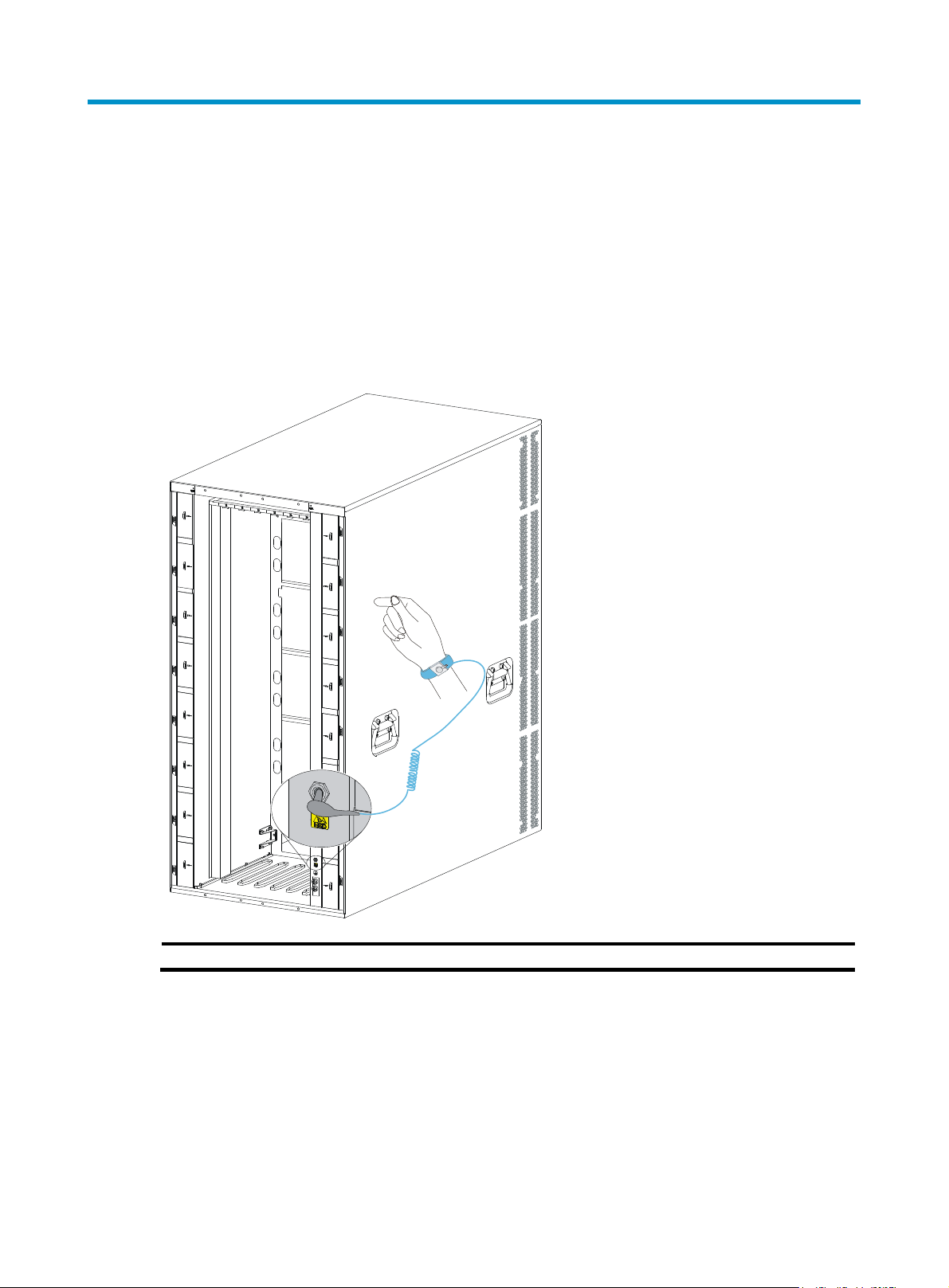
To prevent electronic components from electrostatic discharge (ESD) damage, wear an ESD wrist strap
and make sure it makes good skin contact and is reliably grounded before you touch any switch
module.
Figure 1 Attaching an ESD wrist strap (S12516X-AF switch)
(1) ESD jack (with an ESD sign)
Examining the installation site
The switch must be used indoors. To make sure the switch operates correctly and to prolong its service
lifetime, the installation site must meet the load-bearing, temperature, humidity, cleanness, EMI,
grounding, power supply, ventilation, and space requirements. Reserve a minimum of 1.2 m (3.94 ft) of
clearance between the switch and walls or other devices. For more information, see H3C S12500X-AF
Switch Series Installation Guide.
1
Page 6

Installation tools and equipment
No installation tools and equipment are provided with the switch. Prepare them yourself.
2
Page 7
Installing the switch
Switch dimensions
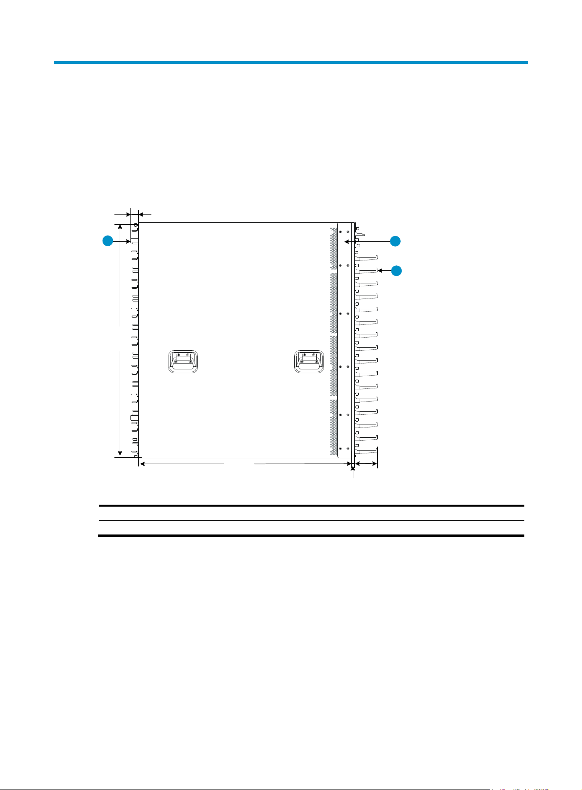
Figure 2 S12516X-AF switch dimensions
30 mm
(1.18 in)
1
931 mm
(36.65 in)
(1) Fan tray handle
(3) Cable management bracket
845 mm
(33.27 in)
2
90 mm
(3.54 in)
12 mm
(0.47 in)
(2) Mounting bracket
3
3
Page 8
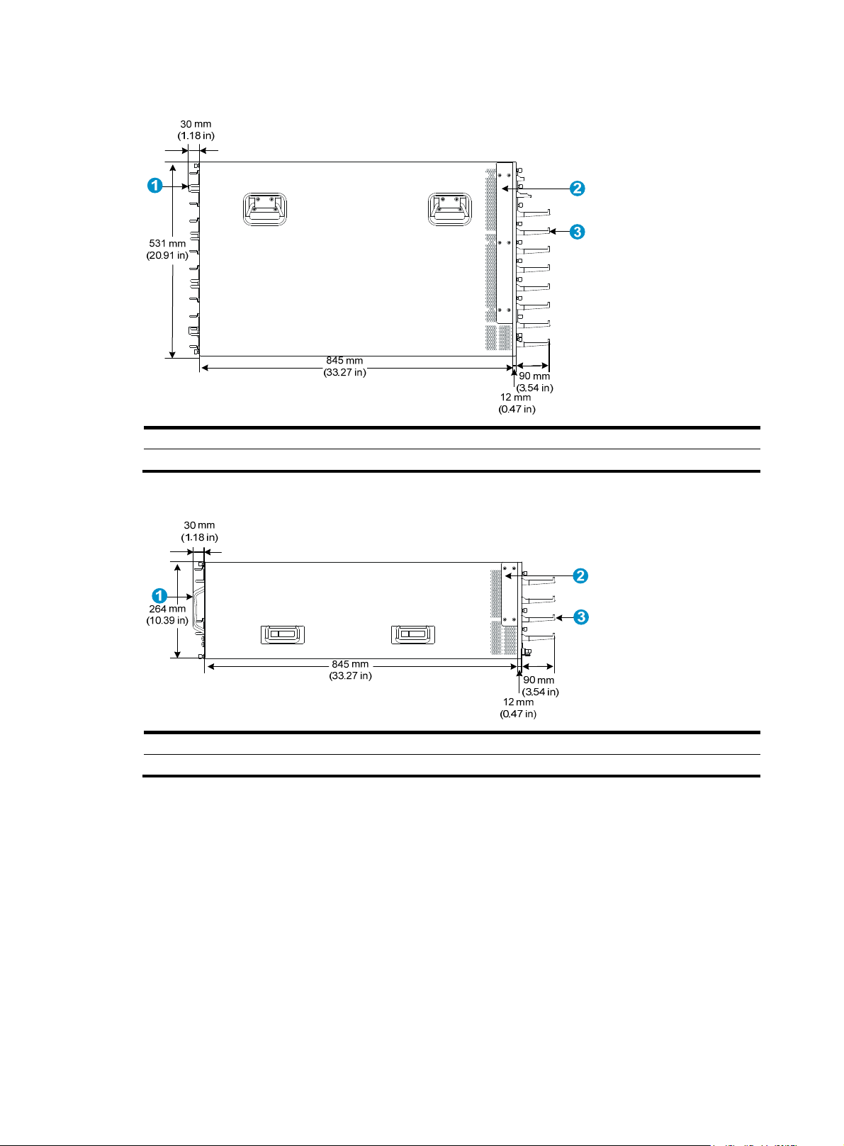
Figure 3 S12508X-AF switch dimensions
(1) Fan tray handle
(2) Mounting bracket
(3) Cable management bracket
Figure 4 S12504X-AF switch dimensions
(1) Fan tray handle (2) Mounting bracket
(3) Cable management bracket
4
Page 9

Rack requirements
Table 1 Rack requirements
Model Switch dimensions
• Height—931 mm (36.65 in) (21 RU).
• Width—440 mm (17.32 in).
• Total depth—977 mm (38.46 in)
{ 857 mm (33.74 in) for the chassis.
S12516X-AF
{ 102 mm (4.02 in) from the mounting
bracket rear ear to the management
bracket front end.
{ 30 mm (1.18 in) for the fan tray
handle at the chassis rear.
• Height—531 mm (20.91 in) (12 RU).
• Width—440 mm (17.32 in).
• Total depth—977 mm (38.46 in)
{ 857 mm (33.74 in) for the chassis.
S12508X-AF
{ 102 mm (4.02 in) from the mounting
bracket rear ear to the management
bracket front end.
{ 30 mm (1.18 in) for the fan tray
handle at the chassis rear.
• Height—264 mm (10.39 in) (6 RU).
• Width—440 mm (17.32 in).
• Total depth—977 mm (38.46 in)
{ 857 mm (33.74 in) for the chassis.
S12504X-AF
{ 102 mm (4.02 in) from the mounting
bracket rear ear to the management
bracket front end.
{ 30 mm (1.18 in) for the fan tray
handle at the chassis rear.
Rack requirements
• A minimum of 1.1 m (3.61 ft) in depth
(recommended.)
• A minimum of 130 mm (5.12 in) from the
front rack post to the front door.
• A minimum of 950 mm (37.40 in) from
the front rack post to the rear door.
• A minimum of 1.1 m (3.61 ft) in depth
(recommended.)
• A minimum of 130 mm (5.12 in) from the
front rack post to the front door.
• A minimum of 950 mm (37.40 in) from
the front rack post to the rear door.
• A minimum of 1.1 m (3.61 ft) in depth
(recommended.)
• A minimum of 130 mm (5.12 in) from the
front rack post to the front door.
• A minimum of 950 mm (37.40 in) from
the front rack post to the rear door.
NOTE:
H3C recommends that you use a rack that has a single door at the front.
Attaching slide rails to the rack
IMPORTANT:
The switch is heavy. Install the slide rails at the lowest possible position.
5
Page 10
g
g
Table 2 Slide rails available for the switch
Switch model
S12516X-AF 350 kg (771.60 lb)
S12508X-AF 190 kg (418.87 lb)
Chassis weight (full
uration)
confi
Applicable slide rails
H3C LSTM2KSGD0 adjustable slide rails:
• Adjustment range—500 mm (19.69 in) to 800 mm (31.50
in).
• Load-bearing capacity—350 kg (771.60 lb).
• Occupied space—2U.
H3C LSVM1BSR10 adjustable slide rails:
• Adjustment range—630 mm (24.80 in) to 850 mm (33.46
S12504X-AF 110 kg (242.50 lb)
in).
• Load-bearing capacity—200 kg (440.92 lb).
• Occupied space—2U.
Attaching the LSTM2KSGD0 slide rails (for the S12508X-AF and S12516X-AF switches)
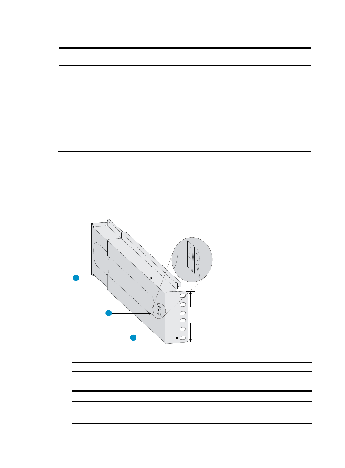
1. Read signs on the slide rails to avoid making a mistake.
Figure 5 Right slide rail
1
2
2RU
3
(1) Guide rail
1 RU = 44.45 mm (1.75 in)
(2) Sign
(3) Installation hole
Table 3 Description for signs on the slide rails
Si
n Meaning Remarks
F/L Front end of the left slide rail Mount this end to the left front rack post.
F/R Front end of the right slide rail Mount this end to the right front rack post.
6
Page 11
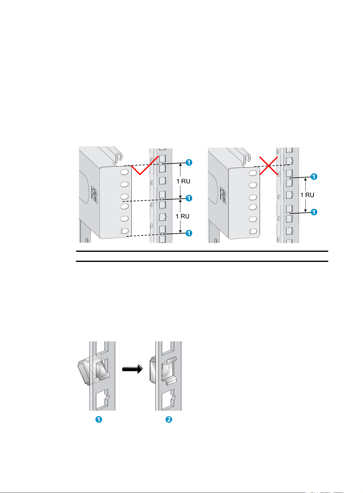
2. Use a slide rail, for example, the right slide rail, to mark the installation position on the rack posts:
a. Make sure the top flange of the slide rail aligns with the middle of the narrower metal area
between holes on the right front rack post, as shown in Figure 6.
One rack unit
(RU) has three holes, the middle of which is an auxiliary installation hole, and
the other two are standard installation holes. You can distinguish them by the space between
each two holes. The space between a standard installation hole and an auxiliary installation
hole is wider than that between two adjacent standard installation holes.
b. Each rack post requires six screws to attach the slide rail. Mark the uppermost square hole
and lowermost square hole on the rack post.
c. Mark the square holes at the same height on the other three rack posts.
Figure 6 Marking the installation position on the rack for the slide rails
(1) Middle of the narrower metal area between holes
3. Install cage nuts in the marked square holes on the rack posts:
a. As shown by callout 1 in Figure 7, insert
the lower ear of a cage nut into the corresponding
installation hole.
b. As shown by callout 2 in Figure 7, c
ompress the upper and lower ears of the cage nut to lead
the upper ear through the hole.
c. Repeat steps a and b to install cage nuts in all the marked square holes in the rack posts.
Figure 7 Installing a cage nut
4. Align the installation holes on the front end of the slide rail with the cage nuts on a front rack post,
and use six screws to attach the slide rail to the rack post, as shown in Figure 8.
7
Page 12
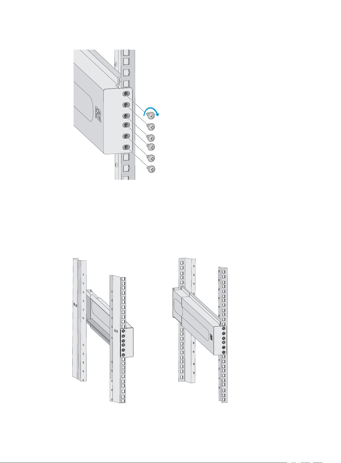
Figure 8 Attaching the right slide rail to the right front rack post
5. Keep the slide rail horizontal and adjust its length until the installation holes on the rear end of the
slide rail touch the cage nuts on the rear rack post. Then use screws to attach the slide rail to the
rear rack post.
Install a screw in each mounting hole of the slide rail to ensure its weight bearing capacity.
6. Repeat steps 4 and 5 to install the other slide rail. Make sure the two slide rails are at the same
height so that the switch can be placed on them evenly. Figure 9 sho
ws the installed slide rails.
Figure 9 Installed slide rails
8
Page 13
Attaching the LSVM1BSR10 slide rails (for the S12504X-AF switch)
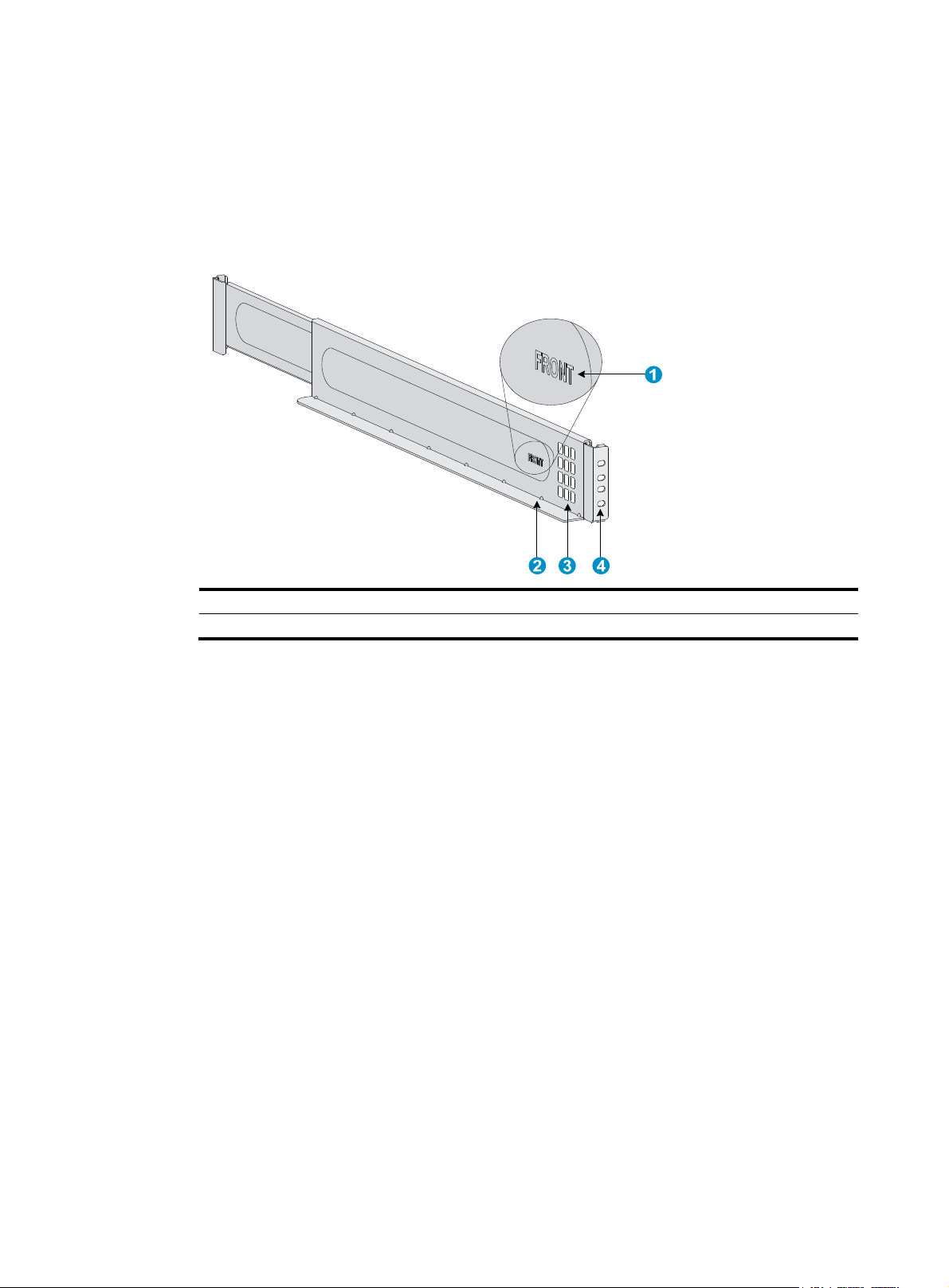
1. Read signs on the slide rails to avoid making a mistake.
Figure 10 Right slide rail
(1) Sign (2) Guide rail
(3) Ventilation holes (4) Installation hole
2. Mark the installation position on the rack posts for the slide rails:
a. Insert the positioning tab at the bottom of a slide rail into the lowest square hole within the 2U
space on a rack post.
Ensure that the installation holes on the slide rail are aligned with the square holes in the rack
post, as shown in Figure 11.
b. Eac
c. Mark the square holes at the same height on the other three rack posts.
h rack post requires four screws to attach the slide rail. Mark the uppermost square hole
and lowermost square hole for installation on the rack post.
9
Page 14
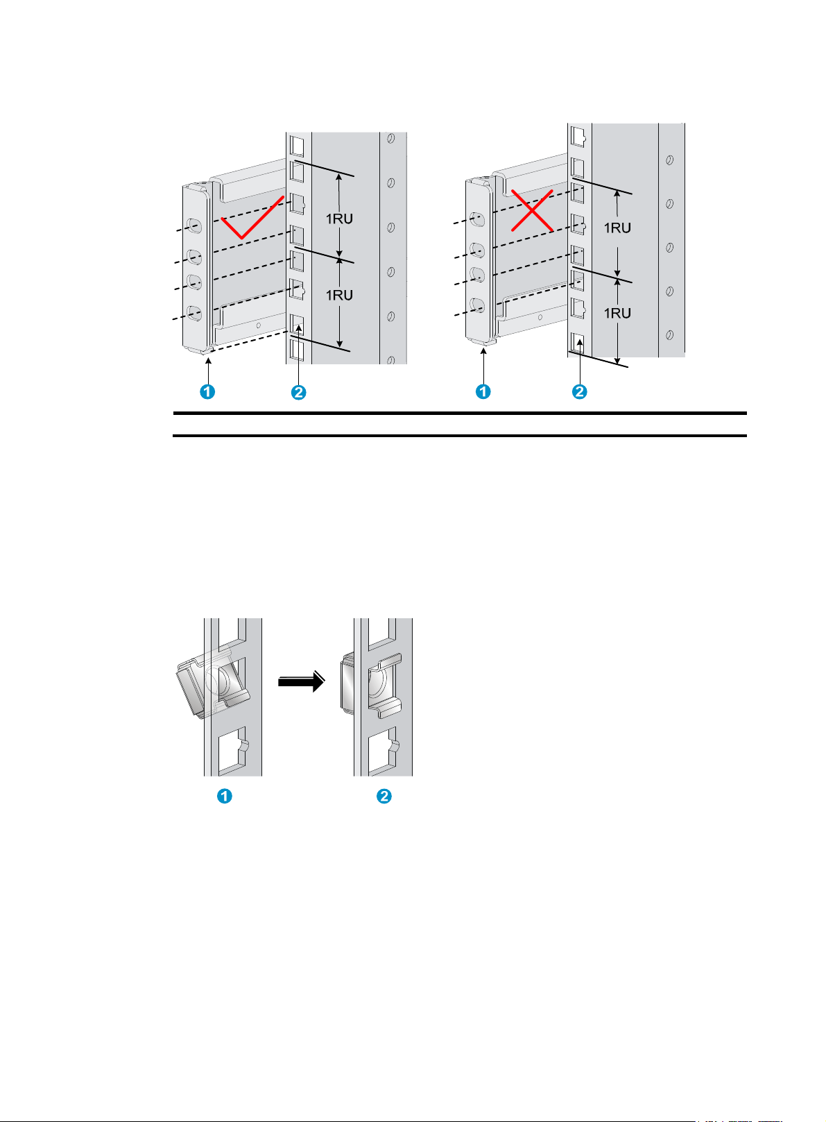
Figure 11 Marking the installation position on the rack for the slide rails
(1) Positioning tab (2) Lowest square hole within the 2U space
3. Install cage nuts in the marked square holes on the rack posts:
a. As shown by callout 1 in Figure 12, in
sert the lower ear of a cage nut into the corresponding
installation hole.
b. As shown by callout 2 in Figure 12, com
press the upper and lower ears of the cage nut to
lead the upper ear through the hole.
c. Repeat steps a and b to install cage nuts in all the marked square holes in the rack posts.
Figure 12 Installing a cage nut
4. Perform the following tasks as shown in Figure 13.
a. Align the installation holes on the two ends of a slide rail with the cage nuts on the front and
rear rack posts.
b. Compress the slide rail, making sure the positioning tabs at both ends of the slide rail are
inserted into the lowest square holes within the 2U space on the rack posts.
c. Use screws to secure the slide rail to the rack posts.
10
Page 15
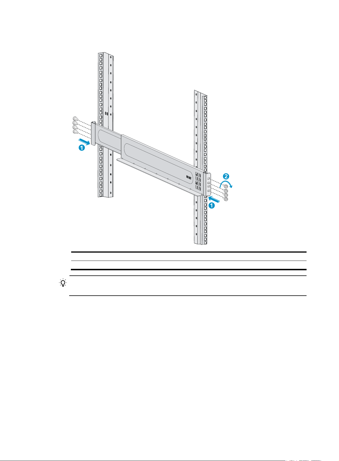
Figure 13 Attaching a slide rail
(1) Compress the slide rail, making sure the positioning tabs are inserted into the square holes
(2) Install fastening screws
TIP:
Install a screw in each mounting hole of the slide rail to ensure its weight bearing capacity.
5. Repeat step 4 to install the other slide rail. Make sure the two slide rails are at the same height so
the device can be placed on them horizontally. Figure 14 sho
ws the installed slide rails.
11
Page 16
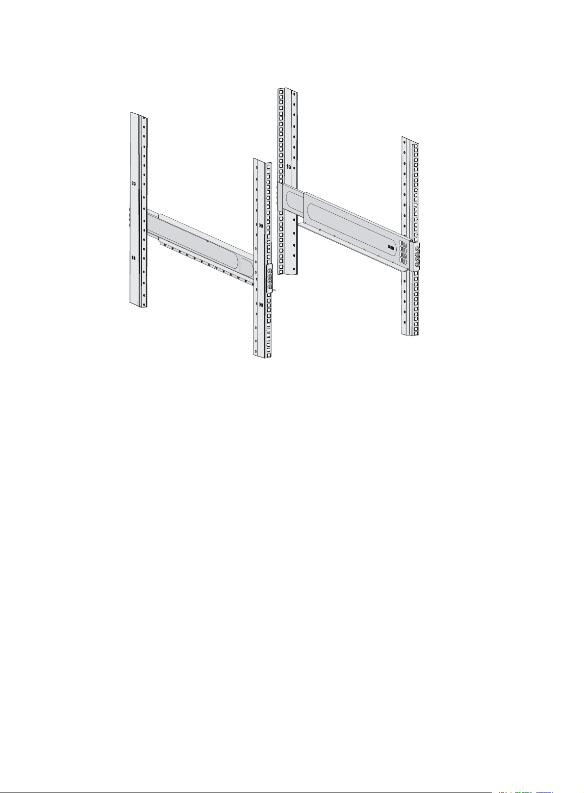
Figure 14 Installed slide rails
Installing cage nuts for attaching mounting brackets
Before mounting the chassis in the rack, install cage nuts on the front rack posts for attaching the
mounting brackets:
1. As shown in Figure 15, Figure 16, and Figure 17, align the bottom edge of a mou
with the top flange of a slide rail. Then mark the cage nut installation holes on the front rack post.
The switch comes with the mounting brackets installed. To determine the cage nut installation
holes, remove a mounting bracket from the switch. You can also directly count the square holes
from the top flange of a slide rail, as shown in Figure 15, Figure 16, and Figure 17.
2. Perform the same step to mark the cage nut installati
3. Install cage nuts in the marked square holes on the front rack posts, as shown in Figure 7.
For the S125
marked square holes on the right front rack post.
For the S12504X-AF switch, install cage nuts in all the marked square holes.
16X-AF and S12508X-AF switches, cage nuts are not needed for the top two
on holes on the other front rack post.
nting bracket
12
Page 17

Figure 15 Installing cage nuts (for the S12516X-AF switch)
1U
3U
3U
3U
1U
3U
3U
3U
1U
13
Page 18

Figure 16 Installing cage nuts (for the S12508X-AF switch)
1U
2U
4U
2U
1U
2U
14
Page 19

g
g
Figure 17 Installing cage nuts (for the S12504X-AF switch)
1U
2U
1U
Mounting the switch in a rack
CAUTION:
• Remove fan trays, power modules, and filler panels from the switch before moving if you lift the
switch manually. Reinstall these components after installing the switch in the rack.
• Do not hold the handle of a fan tray, a power module, or a card, or the air vents of the chassis to
move the switch. Any attempt to carry the switch with these parts mi
even bodily injury.
• After you place the switch on the slide rails, do not leave
might tip the switch, damaging the switch or even causing bodily injury.
To mount the switch in the rack:
1. Face the rear of the chassis towards the front of the rack.
2. Use a minimum of four people to move the switch by holding the chassis handles.
H3C recommends that you use a mechanical lift to lift the switch.
3. Place the switch on the slide rails from the front of the rack and slide the switch along the guide
rails until the mounting brackets on the switch touch the front rack posts tightly, as shown by
callout 2 in Figure 18 or Figure 19.
ht cause equipment damage or
o of your hands immediately because this
4. Use s
crews provided with the switch to attach the mounting brackets to the rack posts.
15
Page 20

For the S12516X-AF and S12508X-AF switches, the name plate on the upper right corner of the
front panel covers two mounting screw holes on the mounting brackets. Screws are not needed
for these two mounting holes.
If the mounting holes in the mounting brackets cannot align with the cage nuts on the rack, verify
the following items:
{ The bottom edge of the slide rail aligns with the middle of the narrower metal area between
holes.
{ The cage nuts are installed in the correct holes.
Figure 18 Mounting the S12508X-AF/ S12516X-AF switch in the rack
1
2
(1) Chassis handle
(3) Use screws to secure the mounting brackets to the rack
3
3
(2) Slide the chassis into the rack
16
Page 21

Figure 19 Mounting the S12504X-AF switch in the rack
(1) Chassis handle
(3) Use screws to secure the mounting brackets to the rack
(2) Slide the chassis into the rack
Grounding the switch
CAUTION:
Grounding the switch reliably is crucial to lightning protection and EMI protection. Ground the switch
reliably before you use it.
17
Page 22

g
Grounding the switch by using a grounding strip
CAUTION:
• Use the grounding cable (yellow-green grounding cable) provided with the switch.
• Connect the
main or lightning rod.
If a grounding strip is available at the installation site, ground the switch by connecting the grounding
cable to the grounding strip.
To connect the grounding cable to the grounding strip:
1. Unpack the grounding cable.
The grounding cable provided with the switch is compliant with the NEBS standards. The
two-hole grounding lug of the grounding cable is used for connecting the chassis. The ring
terminal of the grounding cable is used for connecting the grounding strip.
2. Remove the grounding screws from the grounding holes at the rear of the chassis.
A grounding sign is provided with the grounding holes, as shown by callout 2 in Figure 20.
3. Use groundin
4. Connect the ring terminal of the grounding cable to a grounding post of the grounding strip, and
fasten the grounding cable to the grounding strip with the hex nut.
rounding cable to the earthing system in the equipment room. Do not connect it to a fire
g screws to attach the two-hole grounding lug of the grounding cable to the chassis.
18
Page 23

Figure 20 Connecting the grounding cable to a grounding strip (S12516X-AF switch)
(1) Use grounding screws to attach the two-hole grounding lug to the grounding point
(2) Grounding sign
(5) Ring terminal (6) Hex nut
(3) Grounding strip
(4) Grounding post
Grounding the switch by using the PE wire of an AC power module
CAUTION:
• Make sure the AC power module uses a three-wire cable with a protection wire, and the PE wire of
the AC power module is reliably grounded.
• Make sure the PE connector on the switch is connected securely to the PE wire of the AC power
module.
If the switch is AC powered and no grounding strip is available at the installation site, you can ground
the switch through the PE wire of the AC power module, as shown in Figure 21.
19
Page 24

Figure 21 Grounding the switch by using the PE wire of an AC power module (S12516X-AF switch)
20
Page 25

Installing FRUs
This section describes the installation procedures for the MPUs, LPUs, switching fabric modules, fan trays,
and power modules. For the compatibility matrix between these modules and the switch models, see
H3C S12500X-AF Switch Series Installation Guide.
Attaching an ESD wrist strap
To prevent electronic components from ESD damage, wear an ESD wrist strap and make sure it makes
good skin contact and is reliably grounded before you install FRUs. See Figure 1 f
wrist strap.
Installing MPUs
CAUTION:
• If you are not to install an MPU in an MPU slot, keep the filler panel in the slot.
or attaching an ESD
• When you install an MPU, avoid damaging the connectors on the MPU.
You can install one MPU, or two MPUs for redundancy on the switch. If you are to install one MPU,
install it in either of the MPU slots.
Installing MPUs for the S12516X-AF and S12508X-AF switches
For the S12516X-AF and S12508X-AF switches, the ejector levers of the MPUs and the ejector lever seats
on the MPU slots have pink marks. The MPU installation procedure is the same for the S12516X-AF and
S12508X-AF switches. The following uses the S12516X-AF switch as example.
To install an MPU:
1. As shown by callout 1 in Figure 22, rem
Keep the removed filler panel secure for future use.
2. As shown by callout 2 in Figure 22, orient the MPU with the upside
characters on the MPU. Hold the MPU by the front panel with one hand and support the bottom
with the other. Push the MPU steadily into the slot along the guide rails.
Keep the MPU parallel to the slot to avoid touching other components in the chassis.
3. As shown by callout 3 in Figure 22, pull the ejector levers of the MPU ou
the MPU is inserted in the slot.
ove the filler panel from the target MPU slot.
up based on the orientation of
tward when most part of
4. Push the MPU until the brakes on its ejector levers touch the slot edges tightly.
5. Continue to push the MPU by its middle part on the front panel until you cannot move it.
6. As shown by callout 4 in Figure 22, push
contact with the front panel.
the ejector levers inward until they come in close
21
Page 26

7. As shown by callout 5 in Figure 22, fasten the captive screws on the MPU.
Figure 22 Installing an MPU (S12516X-AF switch)
(1) Loosen the captive screws and remove the filler panel (2) Insert the MPU into the slot
(3) Pull the ejector levers outward (4) Push the ejector levers inward
(5) Fasten the captive screws
Installing MPUs for the S12504X-AF switch
The S12504X-AF switch MPU marks and MPU slot edges are pink-marked.
To install an MPU for the S12504X-AF switch:
1. As shown by callout 1 in Figure 23, rem
Keep the removed filler panel secure for future use.
2. As shown by callout 2 in Figure 23, pivot up the handle of the MPU.
3. As shown by callout 3 in Figure 23, orient the MPU with the upside
characters on the MPU. Hold the MPU by the front panel with one hand and support the bottom
with the other. Push the MPU steadily into the slot along the guide rails.
Keep the MPU parallel to the slot to avoid touching other components in the chassis.
4. As shown by callout 4 in Figure 23, push
tightly.
ove the filler panel from the target MPU slot.
the MPU until the handle breaks touch the slot edges
up based on the orientation of
5. As shown by callout 5 in Figure 23, cont
position.
6. Fasten the captive screws on the MPU.
inue to push the MPU handle until the MPU is secure in
22
Page 27

g
Figure 23 Installing an MPU (S12504X-AF switch)
3
2
1
(1) Loosen the captive screws and remove the filler panel (2) Pivot up the handle
(3) Push the MPU into the slot along the guide rails (4) Push the MPU until the handle breaks touch the
(5) Push the handle until the MPU is secure in position
Installing LPUs
CAUTION:
For heat dissipation of the switch, you must install an LPU in the slot where an interface module adapter
is installed. If you are not to install an LPU in the slot, remove the interface module adapter and install a
filler panel.
The S12500-X LPUs with the dimensions 39.8 × 399.2 × 512.1 mm (1.57 × 15.72 × 20.16 in) and
S12500X-AF LPUs with the dimensions 50 x 433 x 524.4 mm (1.97 x 17.05 x 20.65 in) are available
for the switch. An interface module adapter is required when you install an S12500-X LPU on the switch.
6
4
slot ed
(6) Fasten the screws
es tightly
5
23
Page 28

Installing S12500-X LPUs
Installing an interface module adapter
1. Remove the filler panel from the target slot. See callout 1 in Figure 22.
Keep the removed filler panel secure for future use.
2. As shown in Figure 24, align the adapter rear with the LPU slot and pu
along the guide rails into the slot.
3. As shown by callout 2 in Figure 24, use the sc
secure the adapter to the chassis.
Figure 24 Installing an interface module adapter (S12516X-AF switch)
rews provided with the interface module adapter to
sh the adapter slowly
(1) Push the interface module adapter slowly along the guide rails into the slot
(2) Fasten the screws to secure the interface module adapter to the chassis
Installing an S12500-X LPU
The S12500-X LPU edges and the ejector lever seats on the LPU slots have purple marks.
To install an S12500-X LPU:
1. Loosen the captive screws that secure the LPU to the protection box, pull the ejector levers of the
LPU outward, and pull out the LPU from the protection box. See Figure 25.
2. Hold the LPU
steadily into the target slot along the guide rails with the PCB facing up. Do not touch the
components on the PCB. See Figure 26.
Keep the LPU
3. Pull the ejector levers outward when most of the LPU is inserted into the slot. See callout 2
in Figure 26.
4. Push th
5. Continue to push the LPU by its middle part on the front panel until you cannot move it.
by the front panel with one hand and support its bottom with the other. Slide the LPU
e LPU until the brakes on its ejector levers touch the slot edges tightly.
parallel to the slot to avoid touching other components in the chassis.
24
Page 29

6. Push the ejector levers inward until they come in close contact with the panel. See callout 3
in Figure 26.
7. Fasten the
captive screws to secure the LPU to the interface module adapter. See callout 4
in Figure 26.
Figure 25 Removing an S12
(1) Loosen the captive screws that secure the LPU to the protection box
(3) Pull the LPU out of the protection box
500-X LPU from the protection box
(2) Pull the ejector levers outward
25
Page 30

Figure 26 Installing an S12500-X LPU (S12516X-AF switch)
(1) Push the LPU slowly along the guide rails into the slot (2) Pull the ejector levers outward
(3) Press the ejector levers inward (4) Fasten the captive screws
Installing S12500X-AF LPUs
The S12500X-AF LPU ejector levers and the ejector lever seats on the LPU slots have purple marks.
To install an S12500X-AF LPU:
1. As shown by callout 1 in Figure 27, rem
in Figure 22.
Keep the rem
oved filler panel secure for future use.
ove the filler panel from the target LPU slot. See callout 1
26
Page 31

2. As shown by Figure 27, orient the LPU with the upside up based on the orientation of characters
on the LPU. Hold the LPU by the front panel with one hand and support the bottom with the other.
Push the LPU steadily into the slot along the guide rails.
Keep the LPU parallel to the slot to avoid touching other components in the chassis.
3. As shown by callout 2 in Figure 27, pu
ll the ejector levers of the LPU outward when most part of
the LPU is inserted in the slot.
4. Push the LPU until the brakes on its ejector levers touch the slot edges tightly.
5. Continue to push the LPU by its middle part on the front panel until you cannot push it further.
6. As shown by callout 3 in Figure 27, push
the ejector levers inward until they come in close
contact with the front panel.
7. As shown by callout 4 in Figure 27, fasten the c
aptive screws on the LPU.
Figure 27 Installing an S12500X-AF LPU (S12516X-AF switch)
1
2
2
3
3
4
27
Page 32

g
Installing cable management brackets
The cable management brackets are installed on the two sides of the LPU slots. H3C recommends that
you install cable management brackets after you have installed LPUs.
As shown in Figure 28, inse
management bracket hole until the bracket has close contact with the hole.
Figure 28 Installing a cable management bracket (S12516X-AF switch)
(1) Spring tab on the cable management bracket
(2) Align the cable management bracket with the bracket hole
NOTE:
You must press the spring tab while you are removing a cable management bracket.
rt the cable management bracket end that has a spring tab into the cable
Installing switching fabric modules
CAUTION:
• When you install a switching fabric module, avoid damaging the connectors on it.
• Install switching fabric modules or filler panels in the switchin
the fan tray. Remove the fan tray before you remove the switching fabric modules or filler panels.
• Install filler panels in the empty switching fabric module slots.
• When you hot swap a switching fabric module, only one fan tray is operating and it makes loud
noise. Take protection measures such as wearing an earmuff or earplug. In addition, make good
preparation before hot swapping a switching fabric module to minimize the operation time.
The switch comes with all switching fabric module slots empty. Purchase switching fabric modules and
filler panels for the switching fabric module slots as required.
To install a switching fabric module:
1. Place the switching fabric module on a workbench and remove the protection box from the
connector side of the switching fabric module. See Figure 29.
2. Rel
ease the ejector levers by pressing the spring clips.
fabric module slots before you install
28
Page 33

3. Orient the switching fabric module with the side marked "Up" up. Hold the switching fabric
module front panel near the ejector levers with one hand and support the module bottom with the
other. Place the module bottom on the fan tray guide rails. Align the switching fabric module with
the target slot and insert it into the slot along the guide rails. See callout 1 in Figure 30.
Keep the mod
4. As shown by callout 2 in Figure 30,
ule parallel to the slot to avoid touching other components in the chassis.
continue to push the switching fabric module until the brakes
on its ejector levers touch the slot edges tightly. Simultaneously rotate the ejector levers inward
until the spring clips lock the ejector levers in place and the switching fabric module is completely
seated in the slot.
Figure 29 Removing the switching fabric module from the protection box (S12516X-AF switching
fabric module)
(1) Five screws to secure the protection box to the switching fabric module (2) Loosen the captive screws
(3) Hold the protection box to disengage it from the connector side of the switching fabric module
29
Page 34

Figure 30 Installing a switching fabric module (S12516X-AF switch)
2
1
2
(1) Push the switching fabric module slowly into the slot
(2) Rotate the ejector levers inward until the spring clips lock the ejector levers in place
Installing a filler panel in a switching fabric module slot
The switch comes with empty switching fabric module slots. Install a filler panel in a switching fabric
module slot if you are not to install a switching fabric module in it.
To install a filler panel in a switching fabric module slot:
1. Loosen the captive screws on the ejector levers and rotate outward the ejector levers.
2. Orient the filler panel with the side marked "Up" up. Hold the filler panel front panel near the
ejector levers with one hand and support its bottom with the other. Place the filler panel bottom
gently on the bottom guide rails for the fan tray. Align the filler panel with the switching fabric
module slot. Push the filler panel slowly into the slot along the guide rails. See callout 1 in Figure
31.
Keep the fi
components in the chassis.
ller panel parallel to the switching fabric module slot to avoid touching other
3. As shown by callout 2 in Figure 31, c
ontinue to push the filler panel until the brakes on its ejector
levers touch the slot edges tightly. Simultaneously rotate the ejector levers inward.
4. Fasten the captive screws on the ejector levers.
30
Page 35

Figure 31 Installing a filler panel in a switching fabric module slot (S12516X-AF switch)
(1) Push the filler panel slowly into the slot
(3) Fasten the captive screws on the ejector levers
(2) Simultaneously rotate the ejector levers inward
Removing a filler panel from a switching fabric module slot
1. As shown by callout 1 in Figure 32, loosen the captive screws on the ejector levers.
2. As shown by callout 2 in Figure 32, rotate outward the ejector lev
part way out of the slot.
3. As shown by callout 3 in Figure 32, hold the filler pan
el by the top and bottom edges to pull the
filler panel out of the slot.
Keep the removed the filler panel secure for future use.
ers. Then pull the filler panel
31
Page 36

Figure 32 Removing the filler panel from a switching fabric module slot (S12516X-AF switch)
(1) Loosen the captive screws on the ejector levers
(3) Pull the filler panel out of the slot along the guide rails
Installing fan trays
Follow these restrictions and guidelines when you install a fan tray:
• Install the switching fabric modules before you install a fan tray.
• For good heat dissipation, you must install fan trays in both FAN1 and FAN2 slots. When a fan
tray fails, do not remove it until the new fan tray is ready. The device can operate correctly if the
failed fan tray is still in position.
• The fan tray is hot swappable. Follow these guidelines when you hot swap a fan tray:
{ Ensure electricity safety.
{ Replace a fan tray only when the other fan tray is operating correctly.
{ To avoid power-off protection of the switch caused by high temperature, finish replacing a fan
tray within 3 minutes.
• When you hot swap a fan tray, only one fan tray is operating and it makes loud noise. Take
protection measures such as wearing an earmuff or earplug. In addition, make good preparation
before hot swapping a fan tray to minimize the operation time.
(2) Rotate the ejector levers outward
• Do not power on a switch that does not have any fan trays installed.
32
Page 37

• Before you install or replace a switching fabric module on an operating switch, first remove the fan
tray. Install the fan tray immediately after you finishing installing or replacing the switching fabric
module. Prepare in advance to make sure the whole process is finished within 3 minutes.
Installing fan trays for the S12516X-AF and S12508X-AF switches
IMPORTANT:
The fan tray is high and heavy. To avoid device damage and bodily injury, use two people to install or
remove a fan tray.
To install a fan tray for the S12516X-AF/S12508X-AF switch:
1. Orient the fan tray with the upside up based on the orientation of characters on the fan tray and
align the fan tray with the fan tray slot.
2. Holding the upper fan tray handle with one hand and the lower fan tray handle with the other
hand, insert the fan tray into the slot. Keep the fan tray as straight as possible.
To install a fan tray in FAN1 slot, align the top and left edges of the fan tray in the slot. To install
a fan tray in FAN2 slot, align the top and right edges of the fan tray in the slot.
3. Fasten the captive screws on the fan tray.
33
Page 38

Figure 33 Installing a fan tray (S12516X-AF switch)
(1) Align the fan tray with the fan tray slot (2) Fasten the captive screws
Installing fan trays for the S12504X-AF switch
1. Orient the fan tray correctly.
To install a fan tray in the FAN1 slot, orient the fan tray so that the LEDs are on the left side of the
front panel. To install a fan tray in the FAN2 slot, orient the fan tray so that the LEDs are on the
right side of the front panel.
2. As shown by callout 1 in Figure 34, align the positioning pin on the
hole in the chassis.
3. As shown by callout 2 in Figure 34, hold the fan
Keep the fan tray as straight and stable as possible while inserting it into the slot.
4. As shown by callout 3 in Figure 34, fasten the captive screws on the fan tray.
tray handle and insert the fan tray into the slot.
fan tray with the positioning
34
Page 39

Figure 34 Installing a fan tray for the S12504X-AF switch
(1) Align the positioning pin on the fan tray with the positioning hole in the chassis
(2) Insert the fan tray into the chassis
(3) Fasten the captive screws on the fan tray
Installing power modules
The power module slots are located at the two sides of the rear panel.
To install a power module:
1. Thread the flat-blade screwdriver through the hole in the handle of the filler panel and pull the
filler panel out. See Figure 35.
2. Corr
3. Holding the handle of the power module with one hand and supporting the bottom of the power
ectly orient the power module.
If you install the power module in a left power module slot, make sure the latch is above the
handle. If you install the power module in a right power module slot, make sure the latch is below
the handle.
module with the other, slide the power module along the guide rails into the slot until you hear a
click.
The power module is foolproof. If the power module is oriented incorrectly, you cannot install the
power module into the slot. If you encounter a hard resistance while inserting the power module,
pull out the power module, reorient it, and then insert it again.
35
Page 40

Figure 35 Removing a filler panel (S12516X-AF switch)
Figure 36 Installing a power module (S12516X-AF switch)
Connecting the power cord
CAUTION:
• Power on the switch after you have installed two fan trays on the switch.
• Make sure each power cord has a separate circuit breaker.
• Turn off the circuit breaker before you connect the power cord.
To connect the power cord:
1. Plug the AC power cord connector into the AC input receptacle of the power module.
2. Use a removable cable tie or self-adhesive cable tie (provided with the switch) to secure the
power cord to the handle of the power module.
3. Plug the other end of the power cord into an AC power receptacle, and turn on the circuit
breaker.
36
Page 41

Figure 37 Using a removable cable tie to secure the power cord to the switch (S12516X-AF switch)
(Optional.) Installing transceiver modules
CAUTION:
• Keep the dust plugs in the SFP+/SFP ports if you are not to install transceiver modules or cables in the
ports.
• Install the dust plugs that come with the LPUs in the QSFP+/CXP/CFP2 ports if you are not to install
transceiver modules or cables in the ports.
Installing an SFP+/SFP/QSFP+ module
CAUTION:
• Read the following instructions before you install an SFP+/SFP/QSFP+ module. Failure to follow
these instructions might cause damage to the SFP+/SFP/QSFP+ module.
• Do not remove the dust plug from the SFP+/SFP/QSFP+ module if you are not to connect an optical
fiber to the module.
• Before you install an SFP+/SFP/QSFP+ module, remove the optical fiber (if any) from it.
To install an SFP+/SFP/QSFP+ module:
1. Unpack the module.
Do not touch the golden plating of the module.
37
Page 42

2. Pivot the clasp of the module up. Holding the module, gently push the module into the slot until it
has firm contact with the slot, as shown in Figure 38.
{ For a QSFP+ module that uses a plastic pull latch, skip this step.
{ For an SFP+ module, press the module down so you can push the module straight into the port.
{ If you cannot hold the module by its two sides because of high module density, press the
module on its head end to push it in.
Figure 38 Installing an SFP+/SFP/QSFP+ module (S12516X-AF switch)
Installing a CFP2 module
CAUTION:
• Read the following instructions before you install a CFP2 module. Failure to follow these instructions
might cause damage.
• Before you install or remove a CFP2 module, remove the optical fiber (if any) from it.
To install a CFP2 module:
1. Unpack the CFP2 module.
Do not touch the golden plating of the module.
2. Pivot the module handle up.
3. Correctly orient the CFP2 module and make sure the module handle is on top of the CFP2 module.
Gently push the module into the slot until it clicks into place.
38
Page 43

Figure 39 Installing a CFP2 module (S12516X-AF switch)
Installing a CXP module
CAUTION:
• Read the following instructions before you install a CXP module. Failure to follow these instructions
might cause damage to the CXP module.
• Do not remove the dust plug from the CXP module until you are ready to connect an optical fiber to
the module.
• Before you install a CXP module, remove the optical fiber (if any) from it.
CXP modules are available in two types. One type is with a rubber pull latch and the other is with a
plastic pull latch.
The installation and removal procedures are the same for the CXP modules with a rubber or plastic pull
latch. This guide uses the CXP module with a plastic pull latch as an example.
To install a CXP module:
39
Page 44

W
1. Unpack the CXP module.
Do not touch the golden plating of the module.
2. Correctly orient the CXP module and make sure the pull latch is on top of the CXP module. Gently
push the module into the slot until it has firm contact with the slot.
Figure 40 Installing a CXP module (S12516X-AF switch)
Connecting an SFP+/QSFP+/QSFP+ to SFP+ DAC cable
CAUTION:
hen you connect a fiber cable, make sure the bend radius of the cable is no less than eight times the
fiber diameter.
Use SFP+ DAC cables to connect SFP+ ports, QSFP+ DAC cables to connect QSFP+ ports, and QSFP+
to SFP+ DAC cables to connect QSFP+ and SFP+ ports. All these cables are hot swappable.
To connect an SFP+, QSFP+, or QSFP+ to SFP+ DAC cable:
1. Unpack the cable.
2. Plug the cable connector into the port. Make sure the cable connector is correctly oriented.
40
Page 45

Cabling recommendations
Routing network cables
The cable management brackets are installed on the two sides of the LPU section. H3C recommends
that you route network cables from the left and right sides, as shown in Figure 41.
Figure 41 Routing netw
ork cables (S12516X-AF switch)
41
Page 46

Routing power cords
When you route power cords, take consideration of the layout of the equipment room, including the
locations of the power distribution cabinet, AC power receptacles, and lightning protection box. Place
all re-connecting facilities, such as receptacles, at the rack bottom (Do not place them at a location out
of the rack and easy to reach.)
The power modules of the switch are located at the two sides of the rear panel. H3C recommends that
you route power cords from left and right sides of the switch.
Figure 42 Routing power cords (S12516X-AF switch)
42
Page 47

Accessing the switch
The first time you access the switch you must use a console cable to connect a console terminal, for
example, a PC, to the console port on the switch.
Connecting the console cable
IMPORTANT:
• Identify the mark on the console port and make sure you are connecting to the correct port.
• The serial ports on PCs do not support hot swapping. If the switch has been powered on, connect the
console cable to the PC before connecting to the switch, and when you disconnect the cable, first
disconnect from the switch.
1. Plug the DB-9 female connector of the console cable to the serial port of the PC.
2. Plug the RJ-45 connector of the console cable to the console port of the switch.
Figure 43 Connecting a terminal to the console port (S12516X-AF switch)
43
Page 48

Verification before login
Before you log in to the switch, perform the following tasks:
• Verify that the switch has been correctly installed.
• Verify that all cards have been correctly installed.
• Verify that all the network cables, fibers, power cables, and grounding cables have been correctly
connected.
• Verify that the voltage of the power source is as required.
• Verify that the console cable has been correctly connected, the terminal or PC used for
configuration has started, and the configuration parameters have been set.
• Verify that the switch has been powered on.
Viewing switch startup information
After the switch is powered on, the configuration terminal output startup information. The output
information varies by software versions.
The following shows a sample output you will see when the switch starts up:
System is starting...
Press Ctrl+D to access BASIC-BOOTWARE MENU...
Press Ctrl+T to start memory test
Booting Normal Extended BootWare
The Extended BootWare is self-decompressing..........Done.
****************************************************************************
* *
* BootWare, Version 1.32 *
* *
****************************************************************************
Compiled Date : Jun 18 2013
CPU Type : XLP316
CPU Clock Speed : 1200MHz
Memory Type : DDR3 SDRAM
Memory Size : 4096MB
Memory Speed : 667MHz
BootWare Size : 1536KB
Flash Size : 1012MB
BASIC CPLD Version : 4.0
EXTENDED CPLD Version : 4.0
PCB Version : Ver.B
BootWare Validating...
Press Ctrl+B to access EXTENDED-BOOTWARE MENU...
Loading the main image files...
Loading file flash:/S12500X-AF-CMW710-SYSTEM-R1110.bin......................
44
Page 49

............................................................................
....................................Done.
Loading file flash:/S12500X-AF-CMW710-DEVKIT-R1110.bin....Done.
Loading file flash:/S12500X-AF-CMW710-MANUFACTURE-R1110.bin...Done.
Loading file flash:/S12500X-AF-CMW710-BOOT-R1110.bin........................
............................................................................
.......................Done.
Image file flash:/S12500X-AF-CMW710-BOOT-R1110.bin is self-decompressing....
............................................................................
.....Done.
System image is starting...
Line aux0 is available.
Press ENTER to get started.
Press Enter at the prompt. When the prompt <Sysname> appears, you can configure the switch.
After the switch finishes startup, verify the following items:
• The cooling system is working, and you can hear fan rotating noise and feel air being blown out.
• The LEDs on the MPUs show that the system is operating correctly. For more information about LEDs,
see H3C S12500X-AF Switch Series Installation Guide.
45
Page 50

Obtaining documentation
Take the following steps to get latest documents from the H3C website at www.h3c.com.
1. Go to http://www.h3c.com/portal/Technical_Documents.
2. Choose the desired product category and model.
Copyright © 2015, Hangzhou H3C Technologies Co., Ltd.
For more information about the product and installation procedures, log in to www.h3c.com
46
Page 51

Index
A
AC power supply
grounding switch by using AC power supply PE
wire, 19
ac
cess
first time switch access, 43
taching
at
ESD wrist strap, 21
B
acket
br
cable management bracket installation, 28
r
ack cabling recommendations, 41
C
ble
ca
cabling recommendations, 41
co
nnecting power cord, 36
connec
connec
connec
gr
strip, 18
managemen
CFP2
installing, 38
hassis
c
rack cabling recommendations, 41
connec
console cable, 43
f
po
QSFP+ ca
QSFP+ t
SFP+ c
nsole cable
co
connecting, 43
CXP
installing, 39
E
ting QSFP+, 40
ting QSFP+ to SFP+, 40
ting SFP+, 40
ounding the switch by using grounding
t brackets, 28
ting
irst time switch access, 43
wer cord, 36
ble, 40
o SFP+ cable, 40
able, 40
ctrical
ele
attaching ESD wrist strap, 21
co
nnecting power cord, 36
U installation, 21
FR
ounding switch by using AC power supply PE
gr
wire, 19
gr
ounding switch by using grounding strip, 18
ounding the switch, 17
gr
wer module installation, 35
po
vironment
en
examining installation site, 1
D
ES
attaching ESD wrist strap, 21
evention, 1
pr
xamining installation site, 1
e
F
n tray
fa
installation, 32
FR
U
installation, 21
G
ounding
gr
grounding strip, 18
swi
tch, 17
witch by using AC power supply PE wire, 19
s
witch by using grounding strip, 18
s
H
dware
har
attaching ESD wrist strap, 21
c
able management brackets installation, 28
an tray installation, 32
f
U installation, 21
FR
ounding switch, 17
gr
ounding switch by using AC power supply PE
gr
wire, 19
gr
ounding switch by using grounding strip, 18
STM2KSGD0 slide rail, 6
L
VM1BSR10 slide rail, 9
LS
47
Page 52

mounting cage nuts for attaching mounting
brackets, 12
po
wer module installation, 35
ck mounting slide rail, 5
ra
witch installation, 3
s
I
alling
inst
cable management brackets, 28
c
age nuts for attaching mounting brackets, 12
CFP2 tr
co
co
co
CXP tr
ES
e
fa
FR
po
QSFP+ tr
r
ra
SFP tr
SFP+ tr
swi
s
tools and eq
tr
face module adapter
inter
ansceiver module, 38
nnecting an SFP+ cable, 40
nnecting QSFP+ cable, 40
nnecting QSFP+ to SFP+ cable, 40
ansceiver module, 39
D prevention, 1
xamining installation site, 1
n tray, 32
Us, 21
wer module, 35
ansceiver module, 37
ack requirements, 5
ck slide rail, 5
ansceiver module, 37
ansceiver module, 37
tch, 3
witch dimensions, 3
uipment, 2
ansceiver module (optional), 37
installing LPU, 23
L
login
verification, 44
LP
U
installing interface module adapter, 23
2500-X LPU, 24
S1
2500X-AF LPU, 26
S1
M
module
iller panel installation, 30
f
f
iller panel removal, 31
U installation, 21
FR
installing tr
ansceiver (optional), 37
face module adapter installation, 24
inter
LP
U installation, 23, 24
U installation, 21
MP
2500-X LPU installation, 24
S1
2500X-AF LPU installation, 26
S1
2504X-AF fan tray installation, 34
S1
2504X-AF MPU installation, 22
S1
2508X-AF fan tray installation, 33
S1
2508X-AF MPU installation, 21
S1
2516X-AF fan tray installation, 33
S1
2516X-AF MPU installation, 21
S1
witching fabric module installation, 28
s
N
work cable
net
routing network cables, 41
P
P
E wire, 19
po
wer cords
routing power cords, 42
wer module
po
cord, 36
allation, 35
inst
wer supply
po
grounding switch by using AC power supply PE
wire, 19
pr
eparing for installation, 1
eventing
pr
ESD prevention, 1
ocedure
pr
accessing switch for first time, 43
aching ESD wrist strap, 21
att
aching LSTM2KSGD0 slide rail, 6
att
aching LSVM1BSR10 slide rail, 9
att
tatching slide rail, 5
at
nnecting an SFP+ cable, 40
co
nnecting power cord, 36
co
nnecting QSFP+ cable, 40
co
nnecting QSFP+ to SFP+ cable, 40
co
ounding switch by using AC power supply PE
gr
wire, 19
gr
ounding switch by using grounding strip, 18
ounding the switch, 17
gr
installing c
able management brackets, 28
48
Page 53

installing cage nuts for attaching mounting
brackets, 12
installing CFP2 tr
installing CXP tr
installing f
ansceiver module, 38
ansceiver module, 39
iller panel in switching fabric module
slot, 30
inst
alling FRU, 21
installing interf
alling LPU, 23, 24
inst
alling MPU, 21
inst
installing po
installing QSFP+ tr
installing SFP
installing SFP+ tr
alling switch, 3
inst
alling switching fabric module, 28
inst
installing tr
nting switch, 15
mou
emoving filler panel from switching fabric
r
ace module adapter, 24
wer module, 35
ansceiver module, 37
transceiver module, 37
ansceiver module, 37
ansceiver module (optional), 37
module slot, 31
ve
rification before login, 44
iewing switch startup information, 44
v
Q
QSFP+
connecting cable, 40
inst
alling, 37
R
ck
ra
cabling recommendations, 41
inst
allation requirements, 5
installing c
moun
able management brackets, 28
ting cage nuts for attaching mounting
brackets, 12
moun
ting slide rail, 5
nting switch, 15
mou
uting
ro
network cables, 41
wer cords, 42
po
S
alling MPU, 21
inst
S1
2516X-AF
installing fan tray, 33
alling MPU, 21
inst
ety
saf
attaching ESD wrist strap, 21
ounding switch by using AC power supply PE
gr
wire, 19
gr
ounding the switch, 17
ounding the switch by using grounding strip, 18
gr
SFP
alling, 37
inst
SFP+
nnecting cable, 40
co
nnecting QSFP+ to SFP+ cable, 40
co
alling, 37
inst
e
sit
examining installation site, 1
de rail
sli
LSTM2KSGD0, 6
VM1BSR10, 9
LS
tup
star
viewing, 44
tch
swi
cabling recommendations, 41
irst time access, 43
f
ounding, 17
gr
ounding by using AC power supply PE wire, 19
gr
ounding by using grounding strip, 18
gr
allation, 3
inst
ck-mounting, 15
ra
T
ansceiver module
tr
installing (optional), 37
V
ve
rification
before login, 44
vi
ewing
switch startup information, 44
2504X-AF
S1
installing fan tray, 34
inst
alling MPU, 22
2508X-AF
S1
installing fan tray, 33
W
st strap (ESD), 21
wri
49
 Loading...