

Page 1

H3C S10500 Switch Series
Installation Guide
Hangzhou H3C Technologies Co., Ltd.
http://www.h3c.com
Document version: 5PW101-20110520
Page 2

Copyright © 2011, Hangzhou H3C Technologies Co., Ltd. and its licensors
All rights reserved
No part of this manual may be reproduced or transmitted in any form or by any means without prior
written consent of Hangzhou H3C Technologies Co., Ltd.
Trademarks
H3C,
, Aolynk, , H3Care,
, TOP G, , IRF, NetPilot, Neocean, NeoVTL,
SecPro, SecPoint, SecEngine, SecPath, Comware, Secware, Storware, NQA, VVG, V
2
G, VnG, PSPT,
XGbus, N-Bus, TiGem, InnoVision and HUASAN are trademarks of Hangzhou H3C Technologies Co.,
Ltd.
All other trademarks that may be mentioned in this manual are the property of their respective owners
Notice
The information in this document is subject to change without notice. Every effort has been made in the
preparation of this document to ensure accuracy of the contents, but all statements, information, and
recommendations in this document do not constitute the warranty of any kind, express or implied.
Environmental protection
This product has been designed to comply with the environmental protection requirements. The storage,
use, and disposal of this product must meet the applicable national laws and regulations.
Page 3

Preface
The H3C S10500 Switch Series Installation Guide guides you through the installation of your switch. It
covers product overview, preparing for installation, installing the switch, installing modules, setting up
an IRF fabric, connecting your switch to the network, troubleshooting, replacement procedures,
technical specifications, FRUs and compatibility, LEDs, cables, cabling recommendations, and
repackaging the switch.
This preface includes:
• Audience
• Conventions
• Obtaining documentation
• Technical support
• Documentation feedback
Audience
This documentation is intended for:
• Network planners
• Field technical support and servicing engineers
• Network administrators working with the S10500 switch series
Conventions
This section describes the conventions used in this documentation set.
Command conventions
Convention Description
Boldface Bold text represents commands and keywords that you enter literally as shown.
Italic Italic text represents arguments that you replace with actual values.
[ ] Square brackets enclose syntax choices (keywords or arguments) that are optional.
{ x | y | ... }
Braces enclose a set of required syntax choices separated by vertical bars, from which
you select one.
[ x | y | ... ]
Square brackets enclose a set of optional syntax choices separated by vertical bars, from
which you select one or none.
{ x | y | ... } *
Asterisk marked braces enclose a set of required syntax choices separated by vertical
bars, from which you select at least one.
[ x | y | ... ] *
Asterisk marked square brackets enclose optional syntax choices separated by vertical
bars, from which you select one choice, multiple choices, or none.
&<1-n>
The argument or keyword and argument combination before the ampersand (&) sign can
be entered 1 to n times.
Page 4
Convention Description
# A line that starts with a pound (#) sign is comments.
GUI conventions
Convention Description
Boldface
Window names, button names, field names, and menu items are in Boldface. For
example, the New User window appears; click OK.
> Multi-level menus are separated by angle brackets. For example, File > Create > Folder.
Convention Description
< > Button names are inside angle brackets. For example, click <OK>.
[ ]
Window names, menu items, data table and field names are inside square brackets. For
example, pop up the [New User] window.
/ Multi-level menus are separated by forward slashes. For example, [File/Create/Folder].
Symbols
Convention Description
WARNING
An alert that calls attention to important information that if not understood or followed can
result in personal injury.
CAUTION
An alert that calls attention to important information that if not understood or followed can
result in data loss, data corruption, or damage to hardware or software.
IMPORTANT
An alert that calls attention to essential information.
NOTE
An alert that contains additional or supplementary information.
TIP
An alert that provides helpful information.
Obtaining documentation
You can access the most up-to-date H3C product documentation on the World Wide Web at
http://www.h3c.com
.
Click the links on the top navigation bar to obtain different categories of product documentation:
[Technical Support & Documents > Tech
nical Documents] – Provides hardware installation, software
upgrading, and software feature configuration and maintenance documentation.
[Products & Solutions]
– Provides information about products and technologies, as well as solutions.
[Technical Support & Documents > Software Download]
– Provides the documentation released with the
software version.
Technical support
customer_service@h3c.com
http://www.h3c.com
Page 5

Documentation feedback
You can e-mail your comments about product documentation to info@h3c.com.
We appreciate your comments.
Page 6

i
Contents
Product overview·························································································································································· 1
Overview············································································································································································1
Physical architecture ·························································································································································1
Preparing for installation ············································································································································· 4
Safety recommendations ··················································································································································4
General safety recommendations ···························································································································4
Safety with electricity ···············································································································································4
Safety with switch moving ·······································································································································4
ESD prevention ·························································································································································5
Safety with laser ·······················································································································································5
Examining the installation site ·········································································································································5
Weight support requirements··································································································································5
Temperature requirements ·······································································································································5
Humidity requirements ·············································································································································6
Cleanness requirements···········································································································································6
EMI requirements······················································································································································7
Grounding requirements··········································································································································7
Power supply requirements······································································································································7
Cooling requirements···············································································································································7
Space requirement ···················································································································································9
Tools and equipment ························································································································································9
Installing the switch····················································································································································10
Installation flow ······························································································································································10
Inspecting the switch······················································································································································ 11
Installing slide rails and cage nuts to the cabinet······································································································· 11
Installing slide rails················································································································································ 11
Installing cage nuts················································································································································ 12
Installing accessories to the chassis ·····························································································································13
Installing mounting brackets and cable management brackets········································································ 13
Installing an air filter (optional)···························································································································· 16
Mounting the switch to the cabinet ······························································································································ 16
Grounding the switch ····················································································································································17
Grounding the switch with a grounding strip····································································································· 17
Grounding the switch through the PE wire of an AC power supply································································ 18
Installing modules·······················································································································································20
Attaching an ESD-preventive wrist strap······················································································································ 20
Installing a card······························································································································································ 21
Installing a power module············································································································································· 22
Installing a power module ···································································································································· 23
Connecting the power cable································································································································ 25
Installing a transceiver module (optional)···················································································································· 26
Installing an XFP/SFP+/SFP module···················································································································· 26
Connecting an SFP+ cable··································································································································· 27
Setting up an IRF fabric ·············································································································································28
IRF fabric setup flowchart·············································································································································· 28
Planning IRF fabric setup··············································································································································· 29
Preparing for IRF fabric setup ······························································································································ 29
Page 7

ii
Planning the IRF network ······································································································································ 29
Installing IRF member switches ·····································································································································30
Configuring basic IRF settings······································································································································· 30
Connecting the physical IRF ports ································································································································ 30
Accessing the IRF fabric to verify the configuration ··································································································· 31
Connecting your switch to the network ····················································································································32
Concepts ········································································································································································· 32
Common methods of logging in to a switch······································································································· 32
User interfaces supported by the switch ·············································································································32
Console cable························································································································································ 33
Logging in to the switch for the first time ····················································································································· 33
Login prerequisites ················································································································································ 33
Setting up the configuration environment ··········································································································· 34
Setting up the HyperTerminal connection and setting the terminal parameters ············································· 35
Checks before powering on the switch··············································································································· 38
Powering on the switch········································································································································· 38
Checking the startup information of the switch ·································································································· 38
Initially configuring the switch ······································································································································ 40
Configuring a login authentication method········································································································ 40
Configuring the basic access function ················································································································41
Configuration example ········································································································································· 41
Displaying the network configuration ················································································································· 42
Connecting the switch to the network ·························································································································· 43
Connecting your switch to the network through twisted pair cables ······························································· 43
Connecting your switch to the network through optical fibers ········································································· 43
Troubleshooting··························································································································································45
Troubleshooting methods··············································································································································· 45
Troubleshooting the system ··········································································································································· 45
Configuration terminal problems ························································································································· 45
Troubleshooting the switch during the operation······························································································· 46
Power supply system failure·········································································································································· 46
Fan failure······································································································································································· 47
MPU failure····································································································································································· 47
LPU and switching fabric module failure ····················································································································· 48
Interface failure······························································································································································· 48
Technical support ··························································································································································· 49
Replacement procedures ···········································································································································50
Replacing a power module··········································································································································· 50
Replacing a card···························································································································································· 52
Replacing a fan tray ······················································································································································ 53
Removing a fan tray·············································································································································· 53
Installing a fan tray ··············································································································································· 54
Replacing an air filter ···················································································································································· 54
Replacing a transceiver module ··································································································································· 55
Replacing an XFP/SFP+/SFP module·················································································································· 55
Replacing an SFP+ cable ·····································································································································56
Appendix A Technical specifications ······················································································································57
Weights and dimensions··············································································································································· 57
Module power consumption and system power consumption ·················································································· 59
System power consumption·································································································································· 59
Card power consumption····································································································································· 60
Fan tray power consumption································································································································ 60
Page 8

iii
Heat dissipation ·····························································································································································61
Environmental specifications ········································································································································· 61
Noise··············································································································································································· 61
Appendix B FRUs and compatibility matrixes·········································································································62
MPU················································································································································································· 62
LPU··················································································································································································· 62
Switching fabric module················································································································································ 64
Power module································································································································································· 65
Fan tray ··········································································································································································· 65
Air filter ··········································································································································································· 66
Transceiver modules ······················································································································································ 66
AC power cable····························································································································································· 69
Appendix C LEDs······················································································································································72
MPU LEDs········································································································································································ 72
LPU LEDs·········································································································································································· 74
Switching fabric module LEDs······································································································································· 75
Fan tray LEDs ·································································································································································· 76
Power module LEDs························································································································································ 76
Appendix D Cables ··················································································································································77
Ethernet twisted pair cable············································································································································ 77
RJ-45 connector ····················································································································································· 77
Cable pinouts························································································································································· 77
Cable type······························································································································································ 78
Pin assignments······················································································································································ 79
Making an Ethernet twisted pair cable ··············································································································· 80
Optical fiber ··································································································································································· 80
Overview································································································································································ 81
Precautions····························································································································································· 82
SFP+ cable······································································································································································ 82
Appendix E Cabling recommendations ··················································································································84
General cabling requirements ······································································································································ 84
Correct use of labels······················································································································································ 84
Cable management requirements ································································································································ 84
Appendix F Repackaging the switch·······················································································································88
Removing cables from the switch ································································································································· 88
Removing the power cable··································································································································· 88
Removing the console cable································································································································· 88
Removing the grounding cable···························································································································· 88
Removing the twisted pair and optical fiber ······································································································ 89
Repackaging the switch accessories···························································································································· 89
Repackaging the power module·························································································································· 89
Repackaging the card··········································································································································· 90
Repackaging the switch chassis ··································································································································· 90
Removing the chassis from the cabinet ··············································································································· 90
Removing the air filter··········································································································································· 91
Removing cable management brackets and mounting brackets ······································································ 91
Repackaging the switch chassis··························································································································· 93
Index ···········································································································································································95
Page 9
1
Product overview
This chapter includes these sections:
• Overview
• Physical architecture
Overview
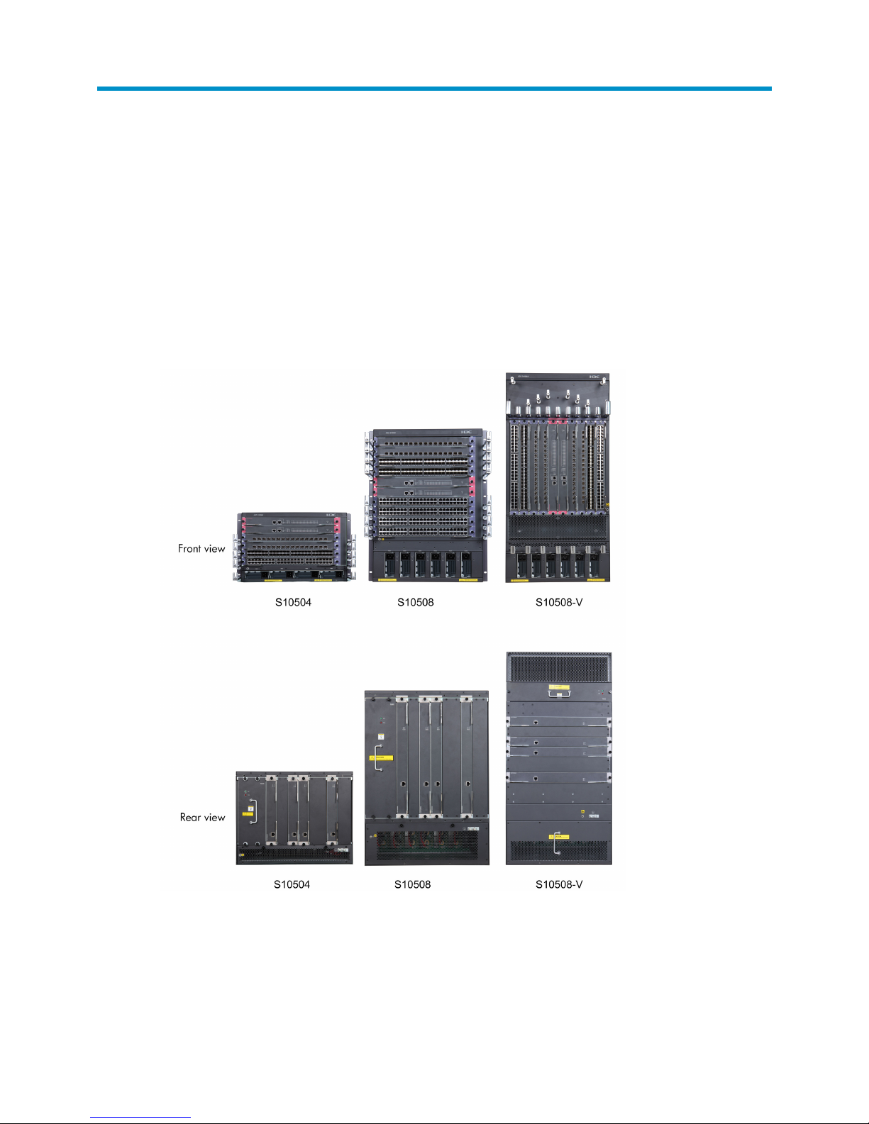
The H3C S10500 Switch Series includes these models: S10504, S10508, and S10508-V.
Figure 1 S10500 Switch Series
Physical architecture
An S10500 switch chassis consists of a main processing unit (MPU) section, line processing unit (LPU)
section, power supply module section, and fan tray section. The following figure uses the S10508 as an
example.
Page 10
2
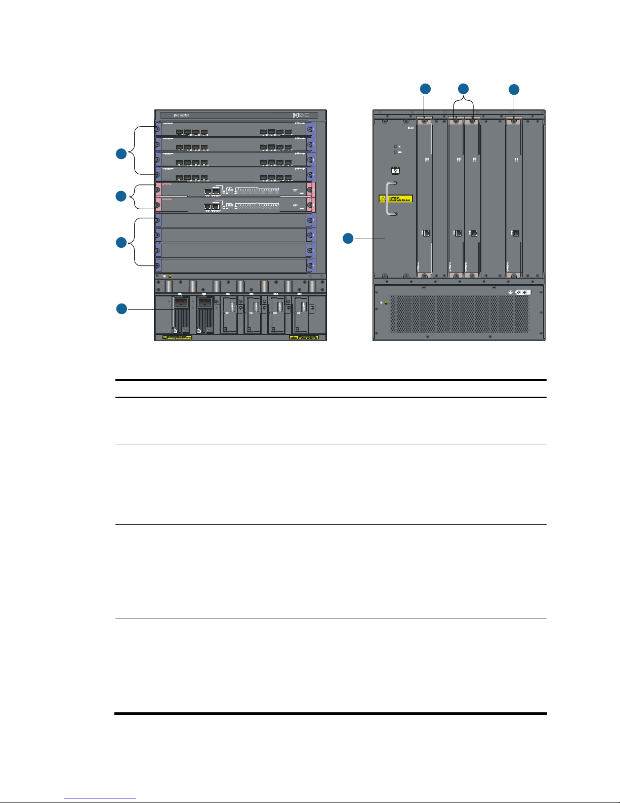
Figure 2 Front and rear views of the S10508
1
2
1
3
4
5 5
5
Table 1 Chassis structure
Section Description Ordering remarks
①
LPU section
Provides slots for LPUs.
Both LPUs and LPU slots have
purple edges.
You must order LPUs separately.
②
MPU section
Provides slots for MPUs, the
supervisor engines that
manage and control the
operations of a switch.
Both MPUs and MPU slots have
pink edges.
You must order MPUs separately, and at least one MPU is
required.
Available MPUs: LSU1SUPA0 (LSUM1SUPA0)
③
Power
module section
Provides slots for power
modules.
• The S10504 provides four
power module slots.
• The S10508 and S10508-V
provide six power module
slots.
You must order power modules separately.
Available power modules: LSUM2AC2500
④
Fan section
Provides a slot for one fan tray.
The location of the fan tray
varies with chassis models:
• S10504 and S10508—Left
rear of the chassis
• S10508-V—Upper rear of
the chassis
By default, each S10500 switch has a fan tray. You do
not need to separately order fan trays.
Page 11

3
Section Description Ordering remarks
⑤
Switching
fabric module
section
Provides four slots for switching
fabric modules.
Both switching fabric modules
and switching fabric module
slots have silver gray edges.
You must order switching fabric modules separately.
At least one switching fabric module is required.
You can install up to four switching modules, and one of
them must be installed in one of the two lowest numbered
switching fabric module slots. In other words, at least one
switching fabric module is required in slot 6 or slot 7 of
the S10504 or in slot 10 or slot 11 of the S10508 or
S10508-V.
NOTE:
• The installation procedures for LPUs, MPUs, and switchin
g
fabric modules are similar. They are called
cards in the following chapters unless otherwise specified.
• For more information about the cards available for the H3C S10500 Switch Series, see the chapter
“Appendix B FRUs and compatibility matrixes.”
Page 12

4
Preparing for installation
This chapter includes these sections:
• Safety recommendations
• Examining the installation site
• Tools and equipment
Safety recommendations
To avoid possible bodily injury and equipment damage, read the safety recommendations in this chapter
carefully before installing an H3C S10500 switch. The recommendations do not cover every possible
hazardous condition.
General safety recommendations
• Keep the chassis clean and dust-free. Do not place the switch on a moist area and avoid liquid
flowing into the switch.
• Make sure that the ground is dry and flat and you have adopted anti-slip measures.
• Keep the chassis and installation tools away from walk areas.
• Do not wear loose clothing, jewelry (for example, necklace) or any other things that could get
caught in the chassis when you install and maintain the switch.
Safety with electricity
• Clear the work area of possible hazards, such as ungrounded power extension cables, missing
safety grounds, and moist floors.
• Locate the emergency power-off switch in the room before installation. Shut the power off at once in
case accident occurs.
• Unplug all the external cables (including power cables) before moving the chassis.
• Do not work alone when the switch has power.
• Always check that the power has been disconnected.
Safety with switch moving
To move an H3C S10500 switch, follow these steps:
• Remove all the external cables (including the power cables) before moving the chassis.
• Use at least two persons to move the switch, and use a mechanical lift if necessary.
• Move the switch carefully.
Page 13

5
CAUTION:
• When moving the switch, hold the handles on the chassis.
• Do not hold the handle of the fan tray, power module,
or back cover of the chassis, or the air vents of
chassis. Any attempt to carry the switch with these parts may cause equipment damage or even bodily
injury.
ESD prevention
To prevent the electric component from being damaged by the electrostatic discharge (ESD), adhere to
the following requirements:
• Ground the switch properly. For how to ground your switch, see the chapter “Installing the switch.”
• Always wear an ESD-preventive wrist strap and make sure it is well grounded when installing field
replaceable units (FRUs). For how to use an ESD-preventive wrist strap, see the chapter “Installing
modules.”
• Hold a PCB by its edges. Do not touch any electronic components or printed circuit.
• Put cards in an ESD-preventive bag.
Safety with laser
The H3C S10500 Switch Series are class 1 laser products.
WARNING!
The laser inside the optical fiber may hurt your eyes.
Examining the installation site
The H3C S10500 Switch Series can only be used indoors. To ensure that the switch works properly and
to prolong its service lifetime, the installation site must meet the following requirements.
Weight support requirements
Evaluate the floor loading as compared to the actual weight of the switch and its accessories (such as
cabinet, chassis, cards, and power modules, and make sure that the floor can support the weight of the
cabinet and the switch chassis. For more information, see the chapter “Appendix A Technical
specifications.”
IMPORTANT:
When evaluating the floor loading, consider switch capacity expansion (for example, installing a new
card) in the future.
Temperature requirements
To ensure the normal operation of the switch, ensure that the room temperature meets the requirements
described in Table 2.
Page 14

6
Table 2 Temperature requirements
Temperature Range
Operating temperature 0°C to 45°C (32°F to 113°F)
Storage temperature –40°C to +70°C (–40°F to +158°F)
CAUTION:
If condensation appears on the switch when you move it to a high-temperature environment, dry the switch
before powering it on to avoid short circuits.
Humidity requirements
Maintain appropriate humidity in your equipment room, as described in Table 3.
• Lasting high relative humidity tends to cause poor insulation, electricity creepage, mechanical
property change of materials, and corrosion of metal parts.
• Lasting low relative humidity is likely to result in loose screws due to washer contraction, and even
electrostatic discharge (ESD), which causes the circuits to fail.
Table 3 Humidity requirements
Humidity Range
Operating humidity (noncondensing) 10% to 95%
Storage humidity (noncondensing) 5% to 95%
Cleanness requirements
Maintain appropriate cleanness in your equipment room.
• Dust is a hazard to the operating safety of your switch. Dust buildup on the chassis may result in
electrostatic adsorption, which causes poor contact of metal components and contact points,
especially when indoor relative humidity is low. In the worst case, electrostatic adsorption can
cause communication failure. Table 4 sh
ows the dust concentration limit in the equipment room.
• The equipment room should meet strict limits on salts, acids and sulfides to eliminate corrosion and
premature aging of components, as shown in Table 5.
Table 4 Dust concentration limit in the equipment
room
Substance Concentration limit (particles/cu m)
Dust particles
≤ 3 x 10⁴
(No visible dust on desk in three days)
IMPORTANT:
Dust particle diameter ≥ 5 μm
Table 5 Harmful gas limits in an equipment room
Gas Max. (mg/m
3
)
SO2 0.2
Page 15

7
Gas Max. (mg/m3)
H2S 0.006
NH
3
0.05
Cl
2
0.01
EMI requirements
All electromagnetic interference (EMI) sources, from outside or inside of the switch and application
system, adversely affect the switch in a conduction pattern of capacitance coupling, inductance coupling,
electromagnetic wave radiation, or common impedance (including grounding system) coupling. To
prevent EMI, perform the following steps:
• Take measures against interference from the power grid.
• Do not use the switch together with the grounding equipment or lightning-prevention equipment of
power equipment, and keep the switch far away from them.
• Keep the switch far away from high-power radio launchers, radars, and equipment with high
frequency or high current.
• Use electromagnetic shielding when necessary.
Grounding requirements
Using a good grounding system to protect your switch against lightning shocks, interferences, and ESD
is essential to the operating reliability of your switch. Make sure that the resistance between the chassis
and the ground is less than 1 ohm. For more information about the grounding methods of the S10500
Switch Series, see the chapter “Installing the switch.”
Power supply requirements
Perform the following steps to satisfy the power supply requirements of the S10500 Switch Series:
1. Calculate the system power consumption
The system power consumption of an S10500 switch depends on the card type and quantity, and fan
tray power consumption. For more information about the system power consumption of the S10500
Switch Series, see the chapter “Appendix A Technical specifications.”
2. Select power modules according to the system power consumption
To ensure proper operation of the switch, make sure that the maximum output power of the power module
that supplies power to the switch is higher than the system power consumption of the switch. After
determining the system power consumption of the switch, you can select appropriate number of power
modules according to the power consumption requirement of your switch. For more information, see the
chapter “Appendix B FRUs and compatibility matrixes.”
3. Check that the power supply system on the installation site satisfies the input requirements of the
power modules and parameters such as rated voltage.
Cooling requirements
For adequate heat dissipation, plan the installation site according to the airflow of your switch, and
adhere to the following requirements:
Page 16
8
• Leave a clearance of at least 10 cm (3.94 in) around the air intake and exhaust vents.
• The cabinet for installing the switch has a good cooling system.
• The installation site has a good cooling system.
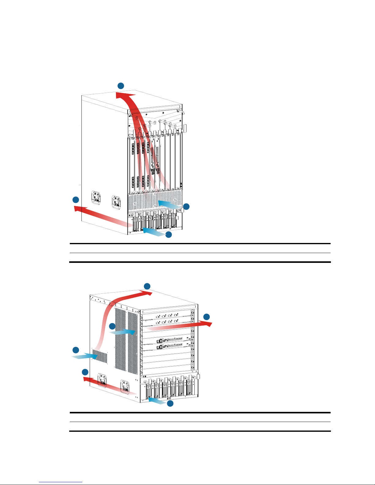
Figure 3 Airflow for the S10508-V
2
4
1
3
1: Air intake for power modules 2: Air exhaust for power modules
3: Air intake for the chassis 4: Air exhaust for the chassis
Figure 4 Airflow for other models of the S10500 Switch Series
1
2
3
3
4
4
1: Air intake for power modules 2: Air exhaust for power modules
3: Air intake for the chassis 4: Air exhaust for the chassis
Page 17

9
Space requirement
For adequate ventilation and ease of maintenance, consider the following space requirements:
• Make sure that the clearance between the cabinet and walls or other devices is at least 1 m (3.28
ft), and the headroom in the equipment room is no less than 3 m (9.84 ft).
• Make sure that the cabinet has enough space (height and depth) to install your switches. For more
information about switch specifications, see the chapter “Appendix A Technical specifications.”
Tools and equipment
Table 6 lists the tools and equipment that you may use when installing an S10500 switch.
Table 6 Tools and equipment list
Category Tool
Measuring and
marking tools
Long tape, ruler (of 1 meter, or 3.28 ft), gradienter, marker, chalk line, and pencil
Drills Percussion drill, electric drill, and several auxiliary drill bits
Fastening tools
Flat-blade screwdriver P4-75 mm
Phillips screwdriver P1-100 mm, P2-150 mm, and P3-250 mm
Socket wrench M5
Socket wrench M6
Small tools
Needle-nose pliers, diagonal pliers, combination pliers, wire-stripping pliers, crimping
pliers, RJ-45 crimping pliers, file, and handsaw
Auxiliary tools
ESD-preventive wrist strap, hair brush, tweezers, paper knife, hand bellows, electric iron,
solder wire, ladder, cable stripper, vacuum cleaner, crowbar, and rubber hammer
Tools for
fiber-optic
cleaning
Lint-free paper and optical fiber microscope
Equipment
Multimeter, 500 V Megohmmeter for measuring the insulation resistance, error detector,
optical power meter, and earth resistance tester
NOTE:
Tools and equipment are not supplied with the switch. Prepare them by yourself as needed.
Page 18
10
Installing the switch
This chapter includes these sections:
• Installation flow
• Inspecting the switch
• Installing slide rails and cage nuts to the cabinet
• Installing accessori
es to the chassis
• Mounting the switch to the cabinet
• Grounding the switch
IMPORTANT:
Keep the packages of the switch and the components for future use.
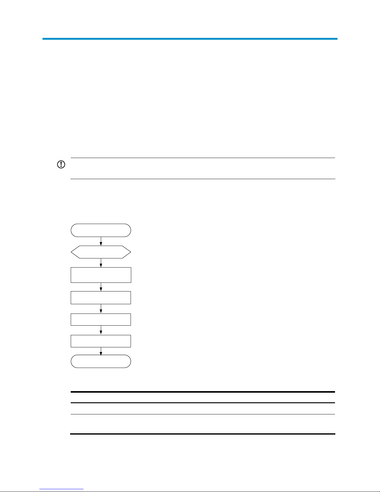
Installation flow
Figure 5 Installation flow
Start
Inspect the switch
Install slide rails and cage
nuts to the cabinet
Install accessories
to the chassis
Install the switch
to the cabinet
End
Ground the switch
Table 7 Description on the installation flow
Step Remarks
Inspecting the switch Preparations before installation
Installing slide rails and
cage nuts to the cabinet
• For how to install slide rails, see “Installing slide rails.”
• For how to install cage nuts, see “Installing cage nuts.”
Page 19

11
Step Remarks
Installing accessories to
the chassis
Accessories to be installed on the chassis:
• For how to mount brackets and cable management brackets, see “Installing
mounting brackets and cable management brackets.”
• For how install an air filter (optional), see “Installing an air filter (optional).”
Mounting the switch to
the cabinet
—
Grounding the switch —
Inspecting the switch
Follow these steps before installing an H3C S10500 switch:
• Make sure that you have read the chapter “Preparing for installation” carefully and the installation
site meets all the requirements.
• Make sure a 19-inch cabinet is ready for use. For how to install a cabinet, see the cabinet
installation guide.
• Make sure that the cabinet is sturdy and securely grounded; the installation position on the cabinet
is appropriate for the chassis; no debris exists inside or around the cabinet.
• Make sure the switch is ready for installation and has been carried to a place near the cabinet and
convenient for moving.
IMPORTANT:
To ensure the stability of the cabinet, mount the switch at the lowest possible position. To mount multiple
switches on the cabinet, mount the heaviest switch at the bottom of the cabinet.
Installing slide rails and cage nuts to the cabinet
Installing slide rails
Before installing the switch to the cabinet, install slide rails to the cabinet. If the cabinet has slide rails,
skip this section.
NOTE:
• Before installing the slide rails, check that the slide rails can support the weight of the switch. For the
weights of the S10500 Switch Series, see the chapter “Appendix A Technical specifications.”
• Position the chassis of the S10500 Switch Series accordin
g
to their heights. For the specifications of the
S10500 Switch Series, see the chapter “Appendix A Technical specifications.”
A 19-inch cabinet is a standardized IEC 60297 system for mounting switches in a cabinet. The height of
front panel of the cabinet is a measurement of one rack unit (RU) (44.45 mm, or 1.75 in). As shown in
Figure 6, ea
ch 1 RU has three holes with center-to-center spacing between the holes of 15.87 mm (0.63
in), 15.87 mm (0.63 in), and 12.70 mm (0.5 in). When installing the slide rails, make sure the bottom
edge of the slide rail aligns with the middle of the narrower metal area between holes.
Follow these steps to install the slide rails:
Page 20
12
Step1 Determine the position of the slide rails on the cabinet.
Step2 Align the screw holes on the two sides of the slide rails with the corresponding holes on the cabinet, and
then fasten the screws.
Step3 Install the other slide rail in the same way. Keep the two slide rails at the same height so that the switch
can be placed evenly.
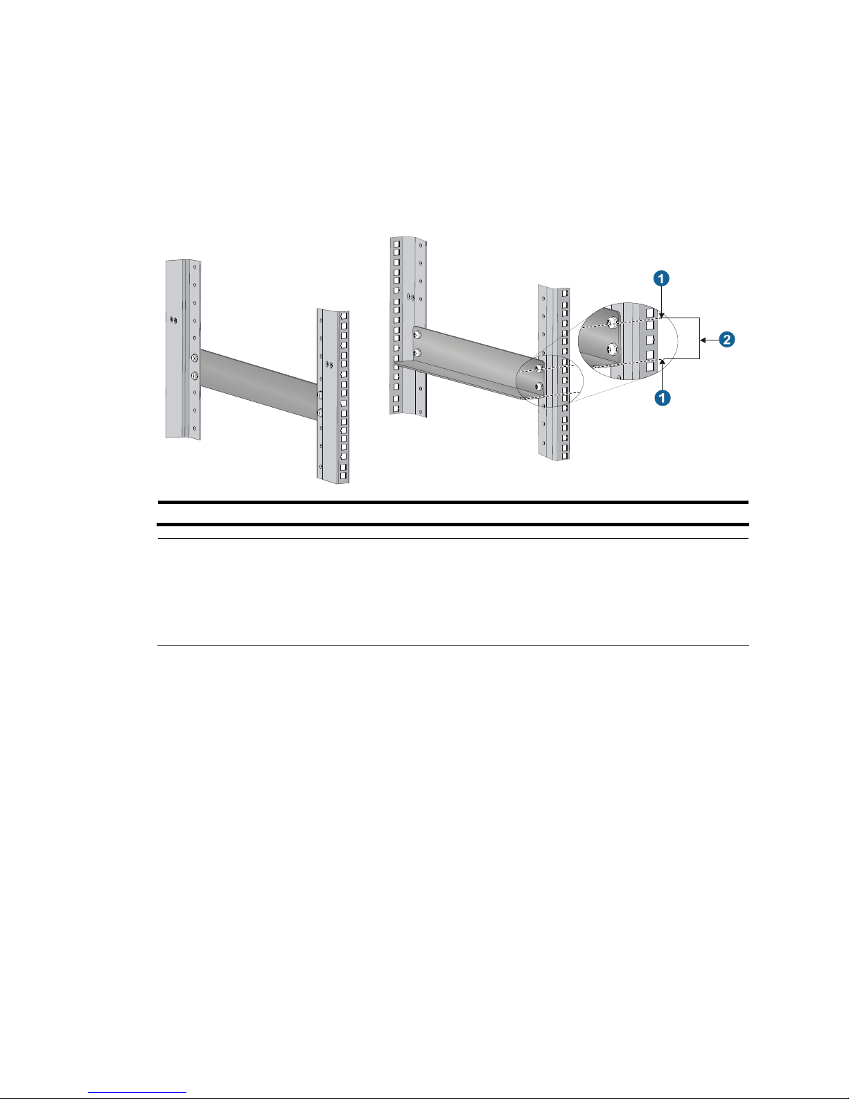
Figure 6 Install the slide rails
1: Middle of the narrower metal area between holes 2: 1 RU
NOTE:
• The appearance and installation methods of slide rails depend on the slide rail types.
• To ensure stability of the cabinet, install the slide rails to the lowest possible position when installin
g a
single switch on the cabinet. To install multiple switches on the cabinet, mount the heaviest switch at the
bottom of the cabinet.
Installing cage nuts
Before mounting the chassis to the cabinet, install cage nuts to the front square-holed brackets of the
cabinet. As shown in Figure 7, det
ermine the positions of the cage nuts according to the holes on the
mounting brackets and positions of the slide rails.
Page 21
13
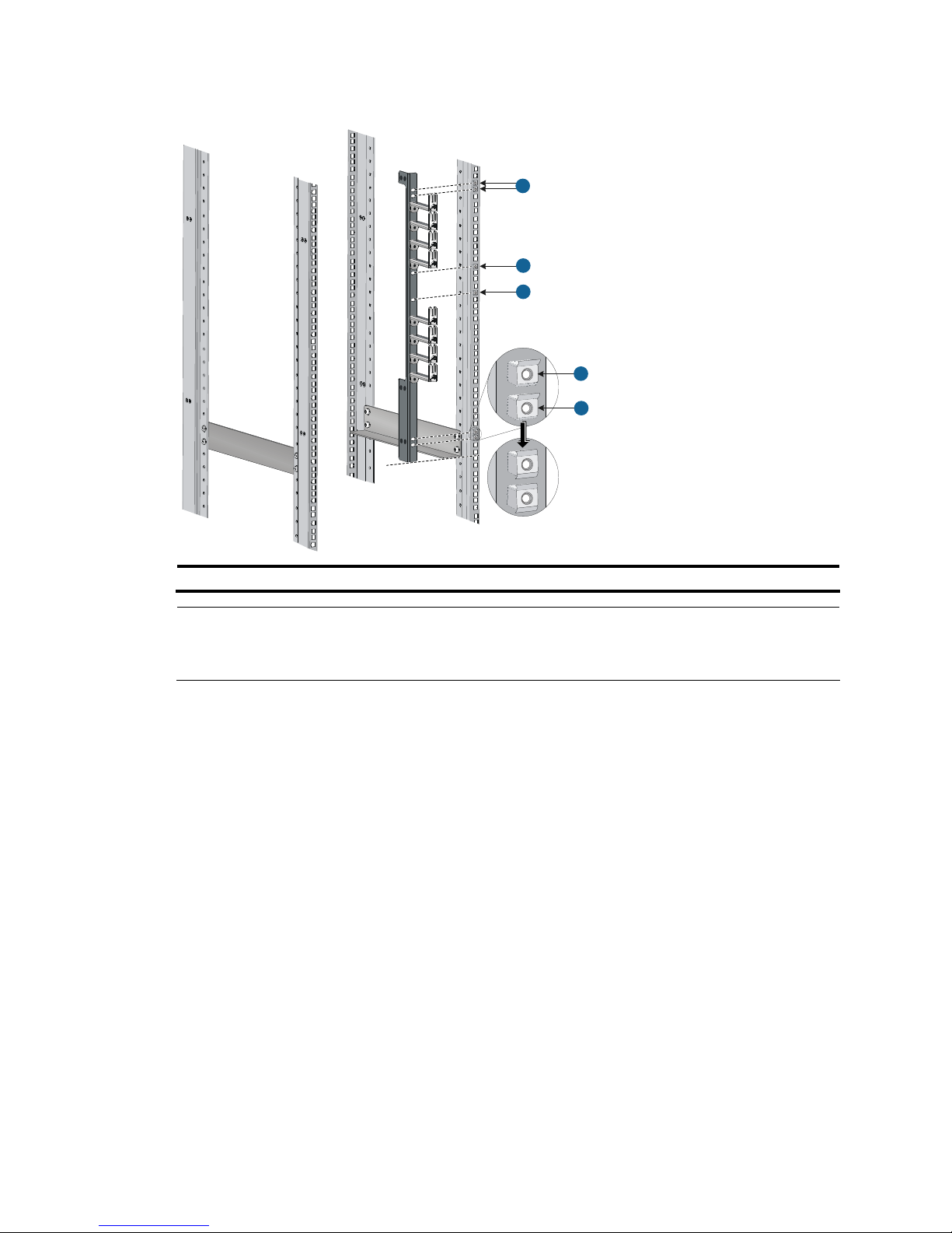
Figure 7 Install the cage nuts (S10508)
1
1
1
1
1
1: Cage nuts
NOTE:
When preparin
g
for installation, make sure that the total height of the switches to be installed is no higher
than the height of the cabinet, and reserve enough clearance for cable routing.
Installing accessories to the chassis
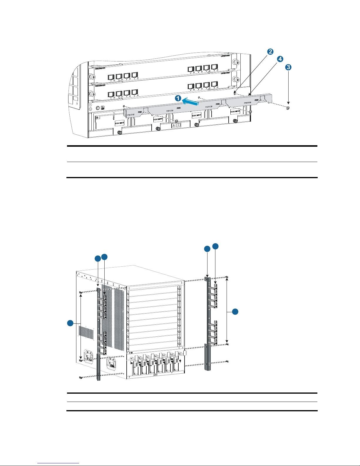
Installing mounting brackets and cable management brackets
Before installing the switch to the cabinet, install the mounting brackets and cable management brackets
shipped with the switch. Mounting brackets are used for fixing the chassis to the cabinet, and cable
management brackets (signal cable and power cable management brackets) for cabling the switch.
• S10508-V: Install the mounting brackets and cable management brackets separately to the chassis.
For more information, see “Installing the cable management brackets” and
“Installing the mounting
brackets.”
• S10508: Install the power cable management brackets to the chassis. The installation procedures
are the same as S10508-V. The signal cable management brackets have been installed to the
mounting brackets when the switch was shipped. For how to install the mounting brackets, see
“Installing the mounting brackets.”
• S10504: The power cable management brackets are installed on the chassis. For how install the
power cable management brackets, see “Installing the cable management brackets.”
The sig nal
cable management brackets have been installed to the mounting brackets when the switch was
shipped. For how to install the mounting brackets, see “Installing the mounting brackets.”
Page 22
14
Installing the cable management brackets
• The S10508-V has two cable management brackets—the signal cable management brackets are
installed at the upper part of the switch, and the power cable management brackets are installed at
the lower part of the switch. They are installed in the same way. For more information, see Figure 8.
• T
he power cable management brackets of the S10504 need to be installed at the lower part of the
switch. For more information, see Figure 9.
F
ollow these steps to install a cable management bracket:
Step1 Unpack the cable management brackets.
Step2 Attach the cable management bracket to the chassis, and align the screws with the screw holes on the
chassis.
Step3 Fasten the screws.
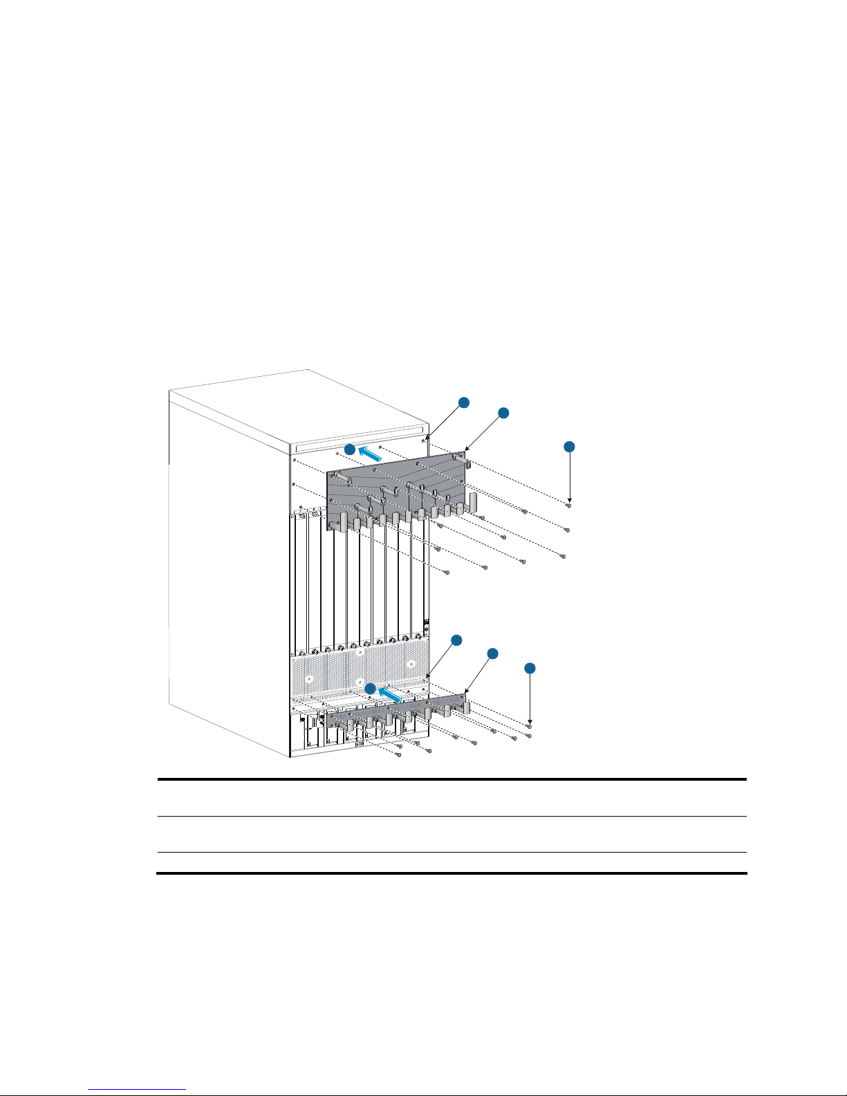
Figure 8 Install cable management brackets on an S10508-V
1
1
2
2
3
3
5
4
1: Attach the cable management bracket to the
chassis
2: Screw holes for installing the cable management
bracket
3: Screws for fixing the cable management bracket to
the chassis
4: Signal cable management bracket (installed at the
upper part of the chassis)
5: Power cable management bracket (installed at the lower part of the chassis)
Page 23
15
Figure 9 Install cable management brackets on an S10504
1: Attach the cable management bracket to the
chassis
2: Screw holes for installing the cable management
bracket
3: Screws for fixing the cable management bracket to
the chassis
4: Power cable management bracket (installed at the
lower part of the chassis)
Installing the mounting brackets
Before installing the switch to the cabinet, install the mounting brackets to the chassis. Marks L and R are
printed inside the mounting brackets to distinguish between the left and right mounting brackets. To
install the mounting brackets, face the front of the switch, and mount the left and right mounting brackets
to the two sides of the switch, as shown in Figure 10.
Figure 10 Install the mounting brackets (S10508)
1
1
2
2
3
3
1: Screws for fixing the mounting brackets to the chassis 2: Mounting brackets
3: Signal cable management brackets
Page 24

16
Installing an air filter (optional)
Air filters of the S10500 Switch Series are optional. If you have ordered air filters, install the air filters
before mounting the switch to the cabinet.
• S10508-V: The air filter is located at the air intake of the front of the switch. For the installation
procedures, see the S10508-V Air Filter User Manual. Before installing an air filter, install the
power cable management brackets to the chassis.
• Other models: The air filter is located at the left of the chassis. For the installation procedures, see
the S10504 Air Filter User Manual and S10508 Air Filter User Manual.
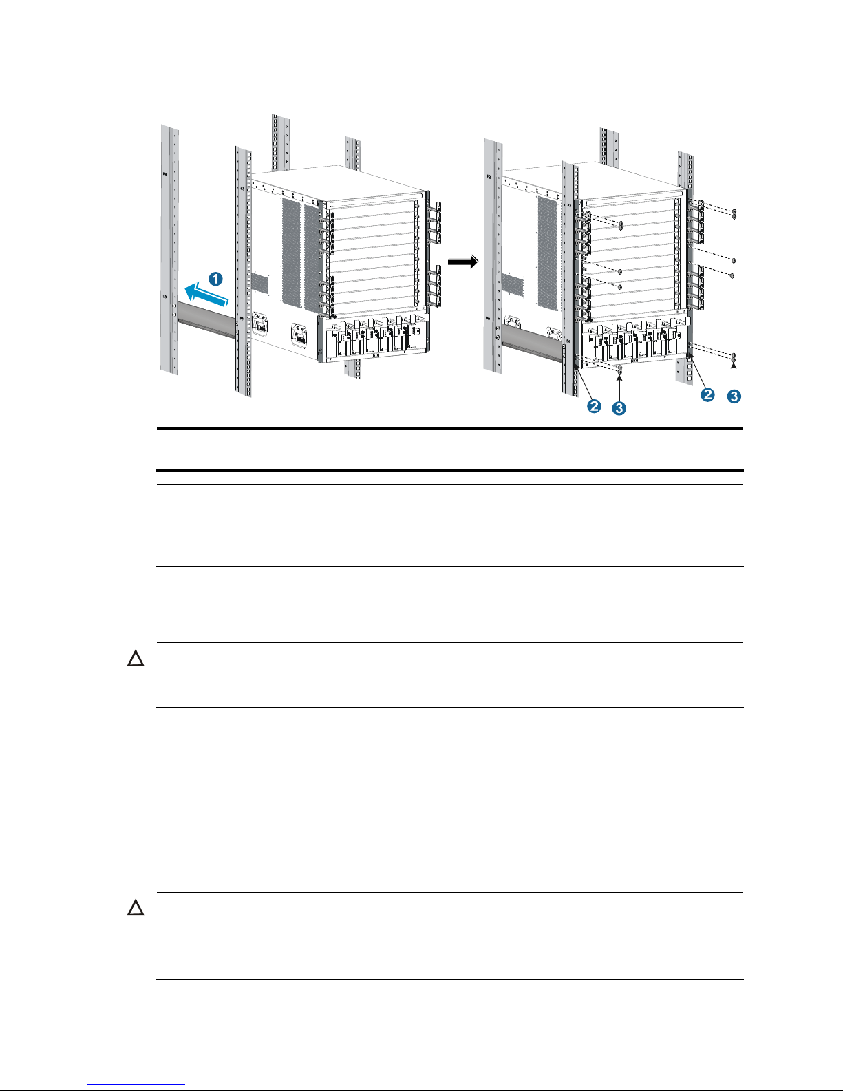
Mounting the switch to the cabinet
Follow these steps to mount the switch to the cabinet:
Step1 Face the rear of the chassis towards the front of the cabinet.
Step2 Use at least two persons to lift the switch by using the handles or supporting the bottom of the chassis
until the bottom of the switch is a little higher than the slide rails on the cabinet.
CAUTION:
• Do not hold the handle of the fan tray, power module, or
the back cover of the chassis, or the air vents
of chassis. Any attempt to carry the switch with these parts may cause equipment damage or even
bodily injury.
• H3C recommends using a mechanical lift for moving your switch.
Step3 Place the switch on the slide rails and slide the switch along the slide rails until the mounting brackets on
the switch touch the front cabinet posts, as shown in callout 1 on Figure 11.
CAUTION:
After placing the switch on the slide rails, do not leave
g
o of your hands immediately because this may tip
and damage the switch, and even cause bodily injury.
Step4 Fix the chassis to the cabinet with mounting screws.
Page 25
17
Figure 11 Install the chassis to the cabinet (S10508)
1: Slide the chassis into the cabinet 2: Mounting brackets
3: Screws for fixing the mounting brackets to the cabinet
NOTE:
If the screw holes on the mounting brackets cannot align with the cage nuts on the cabinet, check that the
bottom edge of the slide rail aligns with the middle of the narrower metal area between holes and that the
cage nuts are installed in the correct holes.
Grounding the switch
CAUTION:
Before using the switch, connect the grounding cable properly to guarantee lightning protection and
anti-interference of the switch.
This section includes these topics:
• Grounding the switch with a grounding strip
• Grounding the switch through the PE wire of an AC power supply
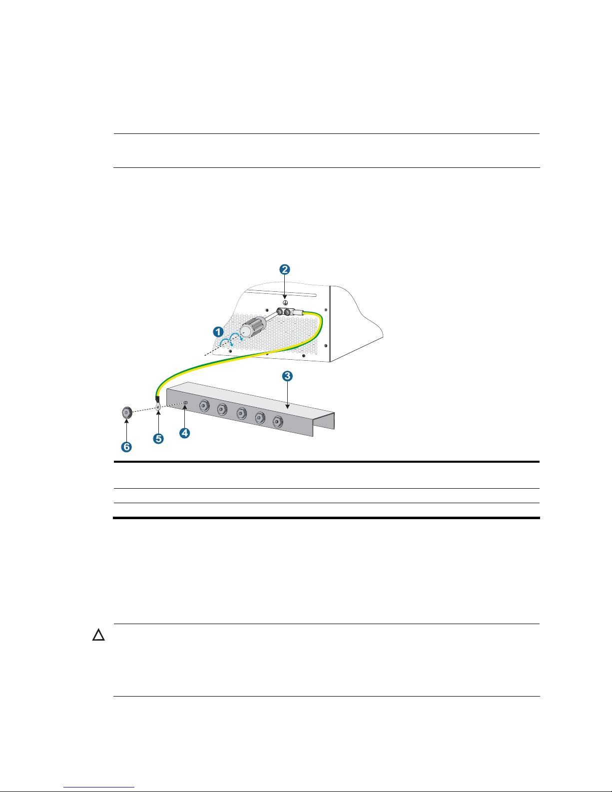
Grounding the switch with a grounding strip
When a grounding strip is available at the installation site, connect the grounding cable through the
grounding strip.
CAUTION:
• Use the supplied grounding cable (yellow-green grounding cable).
• Connect the
g
rounding cable to the earthing system in the equipment room. Do not connect it to a fire
main or lightning rod.
Page 26
18
Follow these steps to connect the grounding cable:
Step1 Take out the grounding cable from the package.
Step2 Remove the grounding screws from the grounding holes on the switch chassis (the grounding holes are
located at the rear of the chassis, as shown in callout 2 on Figure 12.)
.
NOTE:
The grounding cable provided with the S10500 Switch Series is compliant with the NEBS standards.
Step3 Fasten the grounding screws, which are attached with the dual-hole OT terminals of the grounding cable,
into the grounding holes of the chassis.
Step4 Connect the other end (OT terminal) of the grounding cable to the grounding post of the grounding strip,
and fasten the grounding cable to the grounding strip with the hex nut.
Figure 12 Connect the grounding cable to a grounding strip
1: Fix the grounding screws with dual-hole OT terminals to
the grounding holes
2: Grounding sign
3: Grounding strip 4: Grounding post
5: OT terminal 6: Hex nut
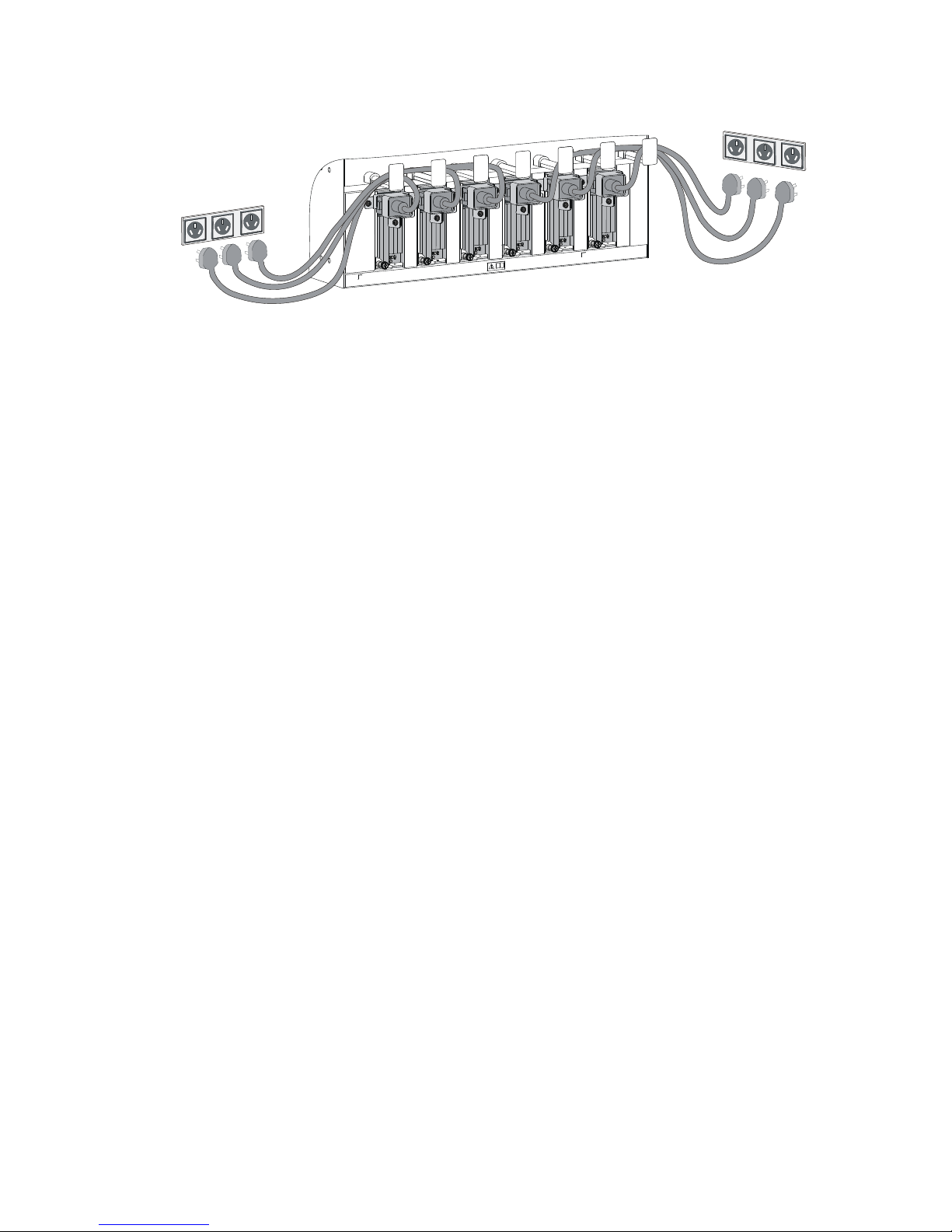
Grounding the switch through the PE wire of an AC power
supply
If the switch is AC powered and no grounding strip is available at the installation site, you can ground
the switch through the PE wire of the AC power supply, as shown in Figure 13.
CAUTION:
Make sure that the AC power supply uses a three-wire cable with a protection wire, and the PE wire of the
AC power supply is well grounded at the power distribution room or AC power supply transformer side.
In addition, make sure that the PE connector on the switch is well connected to the PE wire of the AC power
supply.
Page 27
19
Figure 13 Ground the switch through the PE wire of the AC power supply
Page 28
20
Installing modules
This chapter includes these sections:
• Attaching an ESD-preventive wrist strap
• Installing a card
• Installing a power module
• Installing a transceiver module (optional)
NOTE:
No strict order is required for installing modules. H3C recommends you to install modules, and then
connect the power cable.
IMPORTANT:
Keep the packages of the switch and the components properly for future use.
Attaching an ESD-preventive wrist strap
The S10500 Switch Series provides an ESD-preventive wrist strap. To minimize ESD damage to electronic
components, wear an ESD-preventive wrist strap and ensure it is well grounded when installing modules.
Follow these steps to use an ESD-preventive wrist strap:
Step1 Make sure the switch is well grounded. For how to ground your switch, see the chapter “Installing the
switch.”
Step2 Put on the wrist strap.
Step3 Tighten the wrist strap to keep good skin contact.
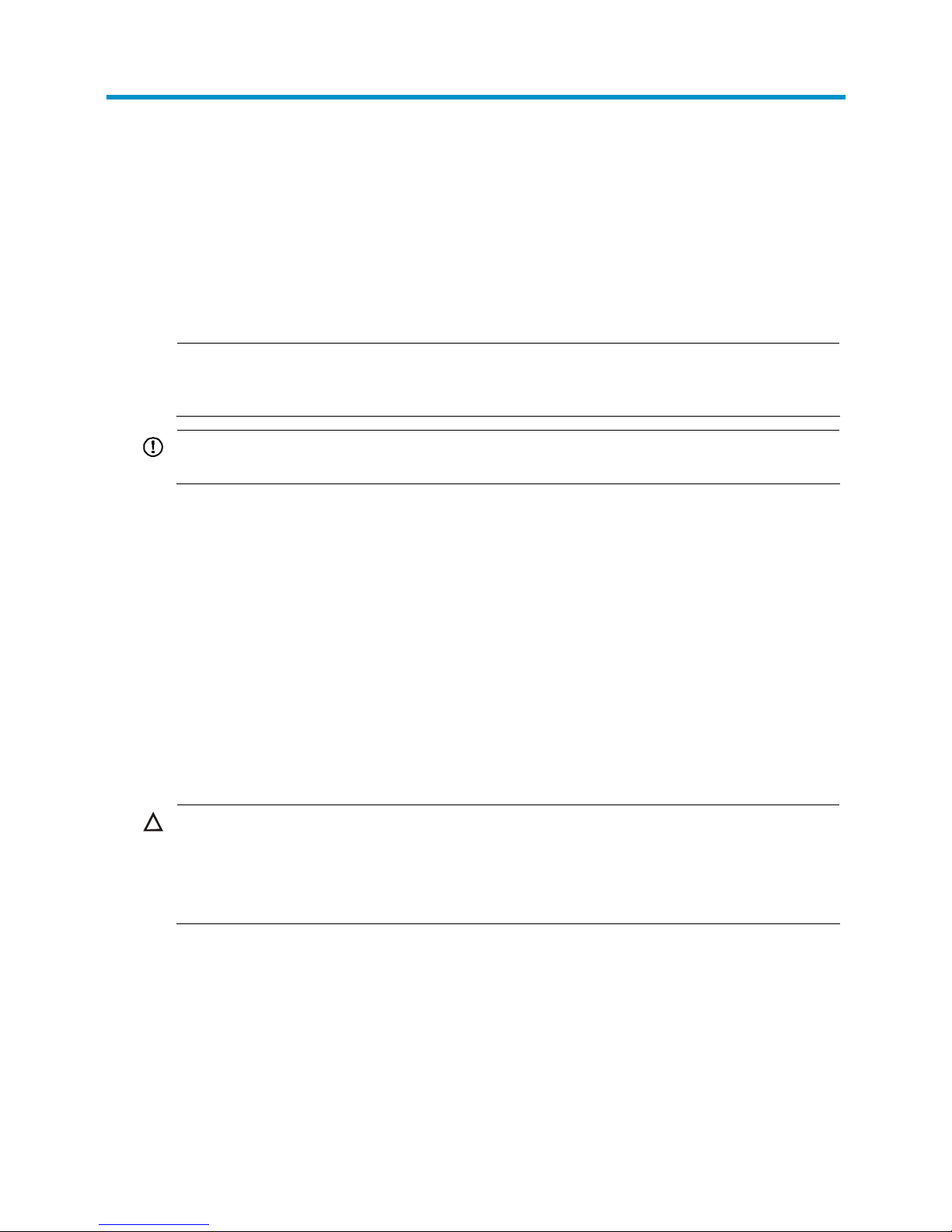
Step4 As shown in Figure 14, insert the ESD-preventive wrist strap into the ESD port on the switch chassis, or
attach it to the grounding screw of the chassis with an alligator clip.
CAUTION:
• Make sure that the resistance reading between your body and the ground is between 1 and 10
megohms.
• Make sure the switch is well grounded. For how to ground the switch, see the chapter “Installing the
switch.”
Page 29
21
Figure 14 Attach an ESD-prevent wrist strap (on an S10508)
1: ESD-preventive wrist strap port (having an ESD sign)
Installing a card
NOTE:
• No blank panel is available on some card slots when your switch is shipped. The figures in this chapter
are for illustration only.
• Before installing a card to the chassis, make sure that the connectors on the card cannot damage the
backplane.
The cards on the S10500 Switch Series include MPUs, LPUs, and switching fabric modules, which can be
installed in horizontal or vertical slots.
• Horizontal slot—with the PCB board on the card facing up
• Vertical slot—with the PCB board on the card facing left
All the cards of the S10500 Switch Series are hot swappable, and the installation procedures are similar.
The following takes a card installed in a horizontal slot as an example.
Follow these steps to install a card:
Step1 Wear an ESD-preventive wrist strap, and make sure it has a good skin contact and is well grounded. For
more information, see “Attaching an ESD-preventive wrist strap.”
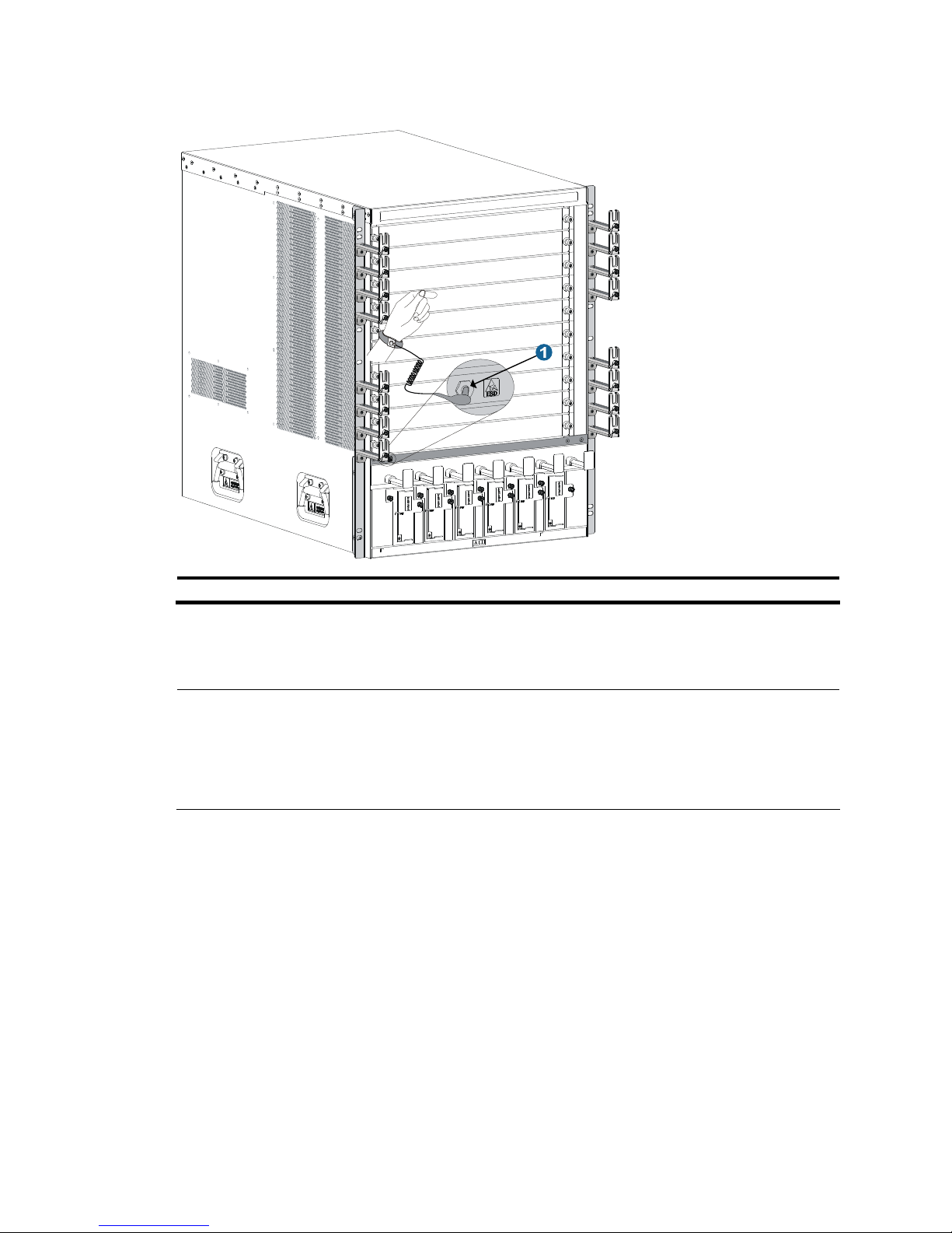
Step2 As shown in callout 1 on Figure 15, remove the blank panel (if any) from the slot to be used. Keep the
blank panel properly for future use.
Page 30
22
Step3 As shown in callout 2 on Figure 15, hold the card by the front panel with one hand and support the card
bottom with the other. Slide the card steadily into the slot along the guide rails.
Step4 When most part of the card is inserted in the slot, press the ejector levers on the card outward.
Step5 Push the card until the positioning pin on card touches the hole on the chassis.
Step6 As shown in callout 3 on Figure 15, press the ejector levers inward until the ejector levers touch the panel
tightly and the card seats into the backplane
Step7 As shown in callout 4 on Figure 15, fasten the captive screws on the card.
Step8 When the switch is powered on, check the running status of the card.
NOTE:
• You can check the runnin
g
status of a card by referring to the card status LED (SLOT) on the MPU of the
switch. If the RUN LED blinks, the card in the slot operates properly. For more information about card
status LED (SLOT), see the chapter “Appendix C LEDs.”
• To ensure ventilation of the switch, install a blank panel (applicable to both MPUs and LPUs) on an
empty slot.
Figure 15 Install a card
1: Loosen the captive screws 2: Insert the card into the slot
3: Press the ejector levers inward 4: Fasten the captive screws
Installing a power module
The S10500 Switch Series adopts N + 1 or N + N power redundancy and supports AC power input.
Page 31

23
CAUTION:
• Provide a circuit breaker for each power module and make sure the circuit breaker is off before
installation.
• Do not install power modules of different models on one switch.
The power modules on the S10500 Switch Series can be installed in horizontal or vertical slots.
• Horizontal slot: S10504
• Vertical slot: S10508 and S10508-V
Strictly follow the order shown in Figure 16 to a
void possible danger.
Figure 16 Power module installation flow
Install the power
module to the chassis
Connect the power
cable
Turn on the circuit
breaker
Installing a power module
CAUTION:
• When movin
g
the power module, support the bottom of the power module, instead of holding its handle
to avoid damaging the power module.
• No blank panel is available on some card slots when your switch is shipped. The figures in this chapter
are for illustration only.
Follow these steps to install the power module:
Step1 Wear an ESD-preventive wrist strap and make sure it has a good skin contact and is well grounded. For
more information, see “Attaching an ESD-preventive wrist strap.”
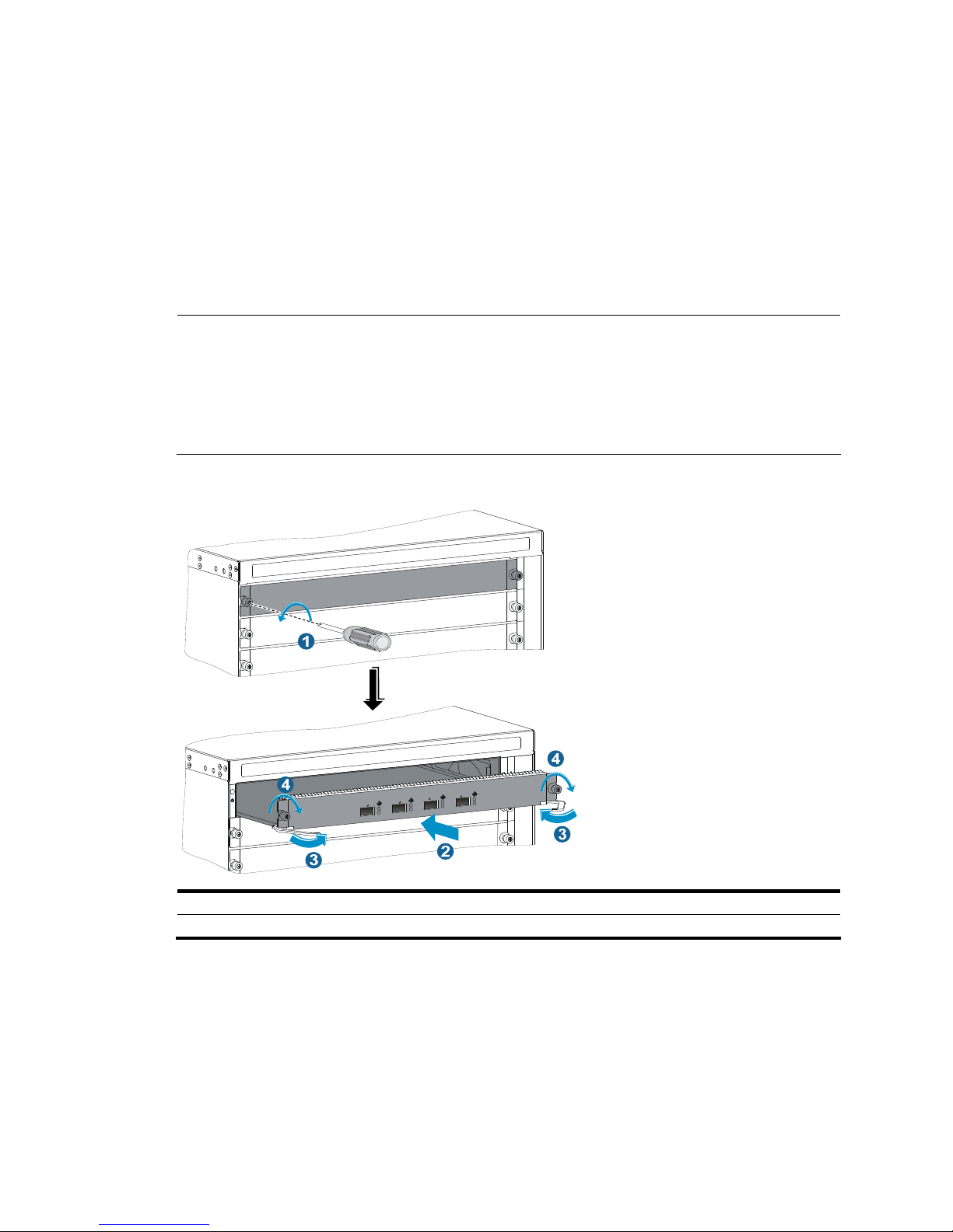
Step2 Use a Phillips screwdriver to loosen the captive screws on the blank panel (if any) to remove the blank
panel.
Step3 Unpack the power module.
Step4 Follow the installation graph printed on the blank panel of the power module to install the power module
in a correct direction. Grasp the handle of the module with one hand and support the module bottom
with the other. Push the power module along the guide rails into the slot until it has firm contact with the
slot. For vertical slot installation, see callout 1 on Figure 17. F
or horizontal slot installation, see callout 1
on Figure 18.
Step5 Press the handle inward until the handle seats into the slot.
Step6 As shown in callout 2 on Figure 17, use a Phillips screwdriver to fasten the captive screw on the handle
to fix the power module.
Page 32

24
Figure 17 Install a power module in a vertical slot
1: Install the power module to the chassis 2: Fasten the captive screw
Page 33

25
Figure 18 Install a power module in a horizontal slot
1: Install the power module to the chassis
Connecting the power cable
WARNING!
Before connecting the power cable, make sure that the circuit breaker on
the power cable is switched off.
Follow these steps to connect the power cable:
Step1 Plug the power cable into the power receptacle.
Step2 Use a cable tie to secure the power cable to the cable management bracket.
• Figure 19 sho
ws how to connect the power cable for a vertical slot switch (S10508 and S10508-V).
• Figure 20 sho
ws how to connect the power cable for a horizontal slot switch (S10504).
Step3 Plug the other end of the power cable to the AC power receptacle and switch on the circuit breaker.
Step4 Check the power module input status LED. If the LED is on, the power cable is properly connected. For
description of power module status LEDs, see the chapter “Appendix C LEDs.”
Page 34

26
Figure 19 Secure the power cable (vertical slot)
Figure 20 Secure the power cable (horizontal slot)
Installing a transceiver module (optional)
Installing an XFP/SFP+/SFP module
CAUTION:
To avoid component damage caused by mis-operation, read this section carefully before installing an
XFP/SFP+/SFP module.
Follow these steps to install an XFP/SFP+/SFP module:
Step1 Wear an ESD-preventive wrist strap and make sure it has a good skin contact and is well grounded. For
more information, see “Attaching an ESD-preventive wrist strap.”
Step2 Unpack the XFP/SFP+/SFP module. Do not touch the golden finger of the module.
Page 35

27
Step3 Pivot the clasp of the module up so that it catches a knob on the top of the module. Holding both sides
of the module, gently push the module into the slot until it has firm contact with the slot (when the top and
bottom spring tabs catch in the slot), as shown in Figure 21.
Figure 21 Install an XFP
/SFP+/SFP module
NOTE:
• When insertin
g
the module to the switch, you can use your finger gently push against the front face of
the module into the slot, rather than inserting it by holding both sides of the module.
• Press down the XFP/SFP+/SFP module a little against the upward force of the bottom spring tab so tha
t
you can insert the XFP/SFP+/SFP module horizontally.
• For how to connect a fiber, see the chapter “Connecting your switch to the network.”
CAUTION:
• Do not remove the protection cover from the XFP/SFP+/SFP module before connectin
g
an optical fiber.
• Remove the optical fiber, if any, from the XFP/SFP+/SFP module before installing it.
Connecting an SFP+ cable
When connecting SFP+ ports located near each other, you can use an SFP+ cable. To connect an SFP+
cable, follow these steps:
Step1 Wear an ESD-preventive wrist strap and make sure it has a good skin contact and is well grounded. For
more information, see “Attaching an ESD-preventive wrist strap.”
Step2 Unpack the SFP+ cable.
Step3 Plug the SFP+ cable into the SFP+ port on the switch. Notice the direction of the cable.
NOTE:
• SFP+ cables are hot swappable.
• Make the bend radius of SFP+ cable at least eight times the cable diameter.
Page 36

28
Setting up an IRF fabric
You can use the Intelligent Resilient Framework (IRF) technology to connect and virtualize S10500
switches into a virtual switch called an “IRF fabric” or “IRF virtual device” for flattened network topology,
high availability, scalability, and manageability.
This chapter includes these sections:
• IRF fabric setup flowchart
• Planning IRF fabric setup
• Installing IRF member switches
• Configuring basic IRF settings
• Connecting the physical IRF ports
• Accessing the IRF fabric to verify the configuration
NOTE:
For more information about IRF, see the
H3C S10500 Switch Series IRF Configuration Guide.
IRF fabric setup flowchart
Figure 22 IRF fabric setup flowchart
Start
Plan IRF fabric
setup
Install IRF member
switches
Power on the switches
Access the IRF fabric to
verify the configuration
End
Configure IRF basic
settings
Connect the physical IRF
ports
NOTE:
The preferred order between configuring basic IRF settings and connecting IRF physical ports depends on
your software release. For the actual procedure, see the
H3C S10500 Switch Series IRF Configuration
Guide
for the software release you are using.
Page 37

29
Planning IRF fabric setup
Preparing for IRF fabric setup
Before you set up an IRF fabric, complete the following tasks:
1. Choose S10500 switch models for your network.
NOTE:
• You can establish an IRF fabric that comprises different S10500 switch models.
• The member switches in an IRF must use the same version of system software image.
2. Select LPUs that can provide 10-GE optical ports.
NOTE:
• The S10500 switch series requires 10-GE optical ports for IRF connection.
• For more information about the LPUs, see the chapter “Appendix B FRUs and compatibility matrixes.”
3. Select transceiver modules (XFP or SFP+) and fibers for long-haul IRF connection, or select SFP+
cables for short-haul IRF connection. For more information about transceiver modules and SFP+
cables, see the chapter “Appendix B FRUs and compatibility matrixes.”
4. Plan the installation site.
Planning the IRF network
Plan the IRF network and identify the role, member ID, physical IRF ports of each member switch.
Identifying the master switch
Determine which switch you want to use as the master for managing all member switches in the IRF
fabric.
An IRF fabric has only one master switch. You configure and manage all member switches in the IRF
fabric at the command line interface of the master.
NOTE:
IRF member switches will automatically elect a master. You can affect the election result by assigning a
high member priority to the intended master switch. For more information about master election, see the
H3C S10500 Switch Series IRF Configuration Guide
.
Planning member IDs
An IRF fabric uses member IDs to uniquely identify and manage its members.
Assign each IRF member switch a unique member ID before connecting them to form an IRF fabric.
Identifying the physical IRF ports on the member switches
Determine which 10-GE ports to use for IRF connection depending on the bandwidth and reliability
requirements.
The S10500 switch series supports link aggregation and cross-card aggregation for IRF ports. You can
bind up to eight physical ports to one IRF port.
Page 38

30
Installing IRF member switches
Follow these steps to install IRF member switches:
Step Reference
Prepare the installation site Chapter 2 “Preparing for installation”
Mount the IRF member switches to cabinets Chapter 3 “Installing the switch”
Install transceiver modules on IRF member switches Chapter 4 “Installing modules”
Configuring basic IRF settings
After you install the IRF member switches, power on the switches, and log in to each IRF member switch
(see the chapter “Connecting your switch to the network”) to configure their member IDs, member
priorities, and IRF port bindings.
Follow these guidelines when you configure the switches:
• You may need to first change the operating mode of the switches to IRF mode depending on your
software release.
• Assign the master switch higher member priority than any other switch.
• Bind physical ports to IRF port 1 on one switch and to IRF port 2 on the other switch. You perform
IRF port binding before or after connecting IRF physical ports depending on the software release.
• Execute the display irf configuration command to verify the basic IRF settings.
For more information about configuring basic IRF settings, see the H3C S10500 Switch Series IRF
Configuration Guide.
Connecting the physical IRF ports
Connect IRF member switches with SFP+ cables or SFP+ transceivers and fibers as planned.
For more information about installing transceiver modules, see the chapter “Installing modules.” For more
information about connecting fibers, see the chapter “Connecting your switch to the network.”
NOTE:
• The transceiver modules at the two ends of an IRF link must be the same type.
• When connectin
g
XFP or SFP+ ports, connect the transmit port of a XFP or SFP+ transceiver module a
t
one end to the receive port of a XFP or SFP+ transceiver module at the other end.
Page 39

31
Figure 23 Connect two IRF member switches
Accessing the IRF fabric to verify the configuration
When you are finished configuring basic IRF settings and connecting IRF ports, follow these steps to
verify the basic functionality of the IRF fabric:
Step1 Log in to the IRF fabric through the console port of any member switch.
Step2 Create a Layer 3 interface, assign it an IP address, and make sure that the IRF fabric and the remote
network management station can reach each other.
Step3 Use Telnet, web or SNMP to access the IRF fabric from the network management station. (See the H3C
S10500 Switch Series Fundamentals Configuration Guide.)
Step4 Check that you can manage all member switches as if they were one node.
Step5 Display the running status of the IRF fabric by using the commands in Table 8.
Table 8 Display and maintain IRF configuration and running status
To do … Use the command…
Display information about the IRF fabric display irf
Display topology information about the IRF fabric display irf topology
NOTE:
• An IRF link failure can cause an IRF fabric to split into two IRF fabrics operating with the same Layer 3
configurations, such as the same IP address.
• To avoid IP address collision and network problems, configure at least one multi-active detection (MAD)
mechanism to detect the presence of multiple identical IRF fabrics and handle collisions. For more
information about MAD detection, see the
H3C S10500 Switch Series IRF Configuration Guide.
Page 40

32
Connecting your switch to the network
This chapter describes how to connect your switch to the network, and includes these sections:
• Concepts
• Logging in to the switch for the first time
• Initially configuring the switch
• Connecting the switch to the network
Concepts
Common methods of logging in to a switch
You can log in to a switch in the following ways.
• Logging in through the console port: Logging in through the console port is the most common login
method, and also the first step to configure other login methods.
• Logging in through telnet/SSH: You can remotely log in to a switch through telnet or SSH to
configure and manage the switch.
NOTE:
For more information about login methods, see the
H3C S10500 Switch Series Fundamentals
Configuration Guide
.
User interfaces supported by the switch
The switch supports the following user interfaces.
• AUX user interface: Manages and monitors users that log in through the console port.
• VTY (virtual type terminal) user interface: Manages and monitors users that log in through Telnet or
SSH. A VTY port is a logical terminal line used for Telnet or SSH access.
NOTE:
On the S10500 Switch Series, the AUX port and the console port are the same port, and are referred to
as “console port” hereafter. You can lo
g
in through the console port through only in AUX user interface
view.
Table 9 User interfaces
User interface Users Port type on the switch
Description
AUX user
interface
Users logging in through
the console port
Console port
A switch allows up to two AUX
users to log in at the same time.
VTY user
interface
Users logging in through
telnet or SSH
Ethernet port
A switch allows up to 16 VTY
users to log in at the same time.
Page 41

33
NOTE:
• On the S10500 Switch Series, the maximum number of AUX users allowed to log in at the same time
depends on the number of main processing units (MPUs), and is two on an S10500 switch installed with
two MPUs.
• After the switches form an IRF virtual device, the maximum number of AUX users allowed to lo
g
in to the
IRF virtual device is the total number of MPUs on these IRF member switches.
Console cable
A console cable is an 8-core shielded cable, with a crimped RJ-45 connector at one end for connecting
to the console port of the switch, and a DB-9 female connector at the other end for connecting to the
serial port on the console terminal.
Figure 24 Console cable
Main label
1
8
B
Pos.9
Pos.1
A
Table 10 Console cable pinouts
RJ-45 Signal DB-9 Signal
1 RTS 8 CTS
2 DTR 6 DSR
3 TXD 2 RXD
4 DCD 5 SG
5 SG 5 SG
6 RXD 3 TXD
7 DSR 4 DTR
8 CTS 7 RTS
Logging in to the switch for the first time
When you log in to the switch for the first time, you can only log in through the console port.
Login prerequisites
Before logging in to the switch for the first time, make the following preparations.
Page 42

34
Table 11 Preparations before the first login
Tool Description
Console cable
An 8-core cable, with an RJ-45 connector at one end and a DB-9 female connector at the
other
Configuration
terminal
A PC with a serial port.
Setting up the configuration environment
Follow these steps to connect the local terminal (a PC in this example) to the console port of the switch
through a console cable, as shown in Figure 25.
Step1 Plug the DB-9 (female) connector of the console cable to the serial interface of the PC on which you
configure the switch.
Step2 Plug the RJ-45 connector of the console cable to the console port of the switch.
CAUTION:
• Identify the port to avoid connection errors.
• Do not plug or unplug the console cable when your switch is powered on, because the serial port of the
PC is not hot swappable. When connecting the PC to your switch, first plug the DB-9 connector of the
console cable to the PC, and then plug the RJ-45 connector of the console cable to your switch. When
disconnecting the PC from your switch, first unplug the RJ-45 connector and then the DB-9 connector.
Figure 25 Set up the environment for local login
Page 43

35
Setting up the HyperTerminal connection and setting the
terminal parameters
To log in to the switch from the local terminal, run the HyperTerminal software on the local terminal. The
following example takes the Windows XP HyperTerminal as an example, and describes how to run it on
the PC.
NOTE:
If you PC runs Windows 2003 Server, add the HyperTerminal component before performin
g
the followin
g
steps to log in to and manage the switch. If your PC runs Windows 2008 server, Windows 7, Windows
Vista, or other operating systems, prepare third-party terminal control software, and follow the usage
guide or help of the software to configure the terminal.
Running the HyperTerminal software and setting up a new HyperTerminal connection named aaa
• Click Start > All Programs > Accessories > Communications > HyperTerminal to enter the
HyperTerminal window. The Connection Description window as shown in Figure 26 a
ppears.
Figure 26 Set up a HyperTerminal connection
• Enter a name (aaa in this example) for the connection, and click OK. Then, the Connect To page as
shown in Figure 27 a
ppears. Select a serial port in the Connecting using drop-down list.
Page 44

36
Figure 27 Select a serial port for the new HyperTerminal connection
• After selecting a serial port, click OK. Then, the COM1 Properties window as shown in Figure 28
appears. On the window, set Bits per second to 9600, Data bits to 8, Parity to None, Stop bits to
1, and Flow control to None.
Figure 28 Set the serial port parameters for the new HyperTerminal connection
• After setting the parameters, click OK. Then, the page as shown in Figure 29 appears.
Page 45

37
Figure 29 The HyperTerminal connection is set up successfully
Setting the attributes for the new HyperTerminal
Select File > Properties on the HyperTerminal window, and the aaa Properties window as shown in
Figure 30 a
ppears. Click the Settings tab. Select VT100 from the Emulation drop-down list, and then click
OK.
Page 46

38
Figure 30 Select the emulation terminal on the aaa Properties window
Checks before powering on the switch
Before powering on the switch, check the following items:
• The switch has been steadily mounted.
• All the cards have been correctly installed.
• The unused slots have been installed with blank panels.
• All the communication cables, fibers, power cables, and grounding cables have been correctly
connected.
• The voltage of power supply can meet the requirements of the switch.
• The console cable has been correctly connected. The configuration terminal has been started, and
the terminal parameters have been configured.
Powering on the switch
Follow these steps to power on the switch:
• Turn on the power supply of the switch.
• Power on the switch.
Checking the startup information of the switch
When the switch is powered on, the configuration terminal displays the following output:
Page 47

39
NOTE:
The output may vary by software version.
System is starting...
Booting Normal Extend BootWare.
The Extend BootWare is self-decompressing...................................
.....Done!
****************************************************************************
* *
* BootWare, Version 1.00 *
* *
****************************************************************************
Compiled Date : Jul 1 2010
CPU Type : XLS408
CPU L1 Cache : 32KB
CPU Clock Speed : 1000MHz
Memory Type : DDR2 SDRAM
Memory Size : 1024MB
Memory Speed : 533MHz
BootWare Size : 508KB
Flash Size : 128MB
BASIC CPLD Version : 0.0
EXTEND CPLD Version : 0.0
PCB Version : Ver.A
BootWare Validating...
Press Ctrl+B to enter extended boot menu...
Starting to get the main application file--flash:/
S10500-CMW520-E1103.bin!................
.........................................................................
The main application file is self-decompressing.............................
............................................................................
..Done!
System application is starting...
Starting to get the main application file--flash:/
S10500-CMW520-E1103.bin!................
..........................................................................
The main application file is self-decompressing.............................
............................................................................
............................................................................
.....Done!
System application is starting...
User interface aux0 is available.
Press ENTER to get started.
Page 48

40
The output shows that the switch has been started. Press Enter and <Sysname> displays. By this time, you
can configure the switch. For more information about initially configuring the switch, see “Initially
co
nfiguring the switch.”
NOTE:
After powering on the switch, check the following items:
• The cooling system is working, and you can hear fan rotating noise and feel air being blown out.
• All the system LEDs on the MPUs are functioning properly. For more information about the LED status,
see the chapter “Appendix C LEDs.”
Initially configuring the switch
By default, the administrator can only log in to the switch through the console port without any
authentication. The default login method does not facilitate remote maintenance and management of the
switch, and brings vulnerabilities to the switch. After the first login, you can perform the following
configurations.
• Configure the login method so that you can remotely maintain and manage the switch and control
login user privileges.
• Configure the access function of the switch to satisfy the requirements of different users.
Configuring a login authentication method
By configuring the authentication mode and the corresponding username, authentication method, and
user privilege level, you can perform login user privilege control, and improve switch security.
The switch supports login through the console port, telnet, SSH, and NMS.
The following section takes login through telnet for example. Login through telnet supports three login
authentication methods.
Table 12 Telnet login authentication methods
Authentication
method
Feature
Application
scenarios
None
Easy to configure, allows any user to Telnet to your switch, and
lowest in security
Lab environments
and extremely
secure network
environments
Password
Easy to configure, allows any user knowing the password to telnet
to your switch, high in security, but incapable of assigning different
privilege levels to different users
Environments that
do not need
granular privilege
management
Username and
password
Complex to configure, allows users inputting the correct username
and password to Telnet to your switch, high in security, and
capable of assigning different privilege levels to different users
Environments
where multiple
operators
cooperate to
manage the switch
Page 49

41
NOTE:
For more information about login methods, see the
H3C S10500 Switch Series Fundamentals
Configuration Guide
.
Configuring the basic access function
When the switch with the default settings accesses the network, it can perform basic data transmission.
To implement more service requirements, you can configure the basic access function on the switch.
Table 13 Basic access function configurations
Function Description
IP addresses Allows you to remotely manage the switch and use the switch in a network.
Static routing Allows the switch to implement routing.
VLAN Divides the network into multiple VLANs, and improves data security.
MSTP Avoids loops in a network using dual uplinks to provide redundancy.
Configuration example
Configuring the Telnet login
# Enter system view.
<Sysname> system-view
# Enter user interface view of VTY 0.
[Sysname] user-interface vty 0
# Configure the authentication mode as password for users logging in through user interface VTY 0.
[Sysname-ui-vty0] authentication-mode password
# Configure the password as hello for users logging in through user interface VTY 0.
[Sysname-ui-vty0] set authentication password cipher hello
# Set the user privilege level to 3 for the users that log in through user interface VTY 0. Then, all users that
log in through Telnet can use all commands.
[Sysname-ui-vty0] user privilege level 3
[Sysname-ui-vty0] quit
Configuring the basic access function
• Configure IP addresses.
# Create VLAN-interface 1.
[Sysname] interface vlan-interface 1
# Assign an IP address to VLAN-interface 1 according to the IP network segment distribution and usage
in the current network. 192.168.0.1 is used as an example.
[Sysname-Vlan-interface1] ip address 192.168.0.1 24
[Sysname-Vlan-interface1] quit
• Configure static routes
# Configure a static route, with the destination IP address 172.16.1.0 and the next hop IP address
192.168.0.2.
Page 50

42
[Sysname] ip route-static 172.16.1.0 255.255.255.0 192.168.0.2
• Configure VLANs
# Create VLAN 10, and enter its view.
[Sysname] vlan 10
[Sysname-vlan10]
# Assign port GigabitEthernet 1/0/1 to VLAN 10.
[Sysname-vlan10] port gigabitethernet 1/0/1
[Sysname-vlan10] quit
• Configure MSTP
# Create an MST region named example, map VLAN 10 to instance 1, and set the MSTP revision level
to 0.
[Sysname] stp region-configuration
[Sysname-mst-region] region-name example
[Sysname-mst-region] instance 1 vlan 10
[Sysname-mst-region] revision-level 0
# Activate the MST region configuration.
[Sysname-mst-region] active region-configuration
[Sysname-mst-region] quit
# Configure the switch as the primary root bridge of instance 1.
[Sysname] stp instance 1 root primary
# Enable MSTP globally.
[Sysname] stp enable
NOTE:
For more information about the access function configuration, see related sections in
H3C S10500 Switc
h
Series Configuration Guides
.
Displaying the network configuration
You can use the following commands to check the software version and configuration information of your
switch, and determine whether the software version and configuration of your switch are correct.
To do… Use the command… Remarks
Display the name, model, and
running operating system version
of the switch
display version Available in any view
Display the current configuration of
the switch
display current-configuration Available in any view
Display the interface status and
configuration
display interface brief Available in any view
Display the IP configuration
information of the specified or all
Layer 3 interfaces
display ip interface brief Available in any view
Display information about active
routes in the routing table
display ip routing-table Available in any view
Page 51

43
To do… Use the command… Remarks
Display VLAN information display vlan Available in any view
Display the spanning tree status
and statistics
display stp brief Available in any view
Connecting the switch to the network
NOTE:
H3C recommends that you perform basic configuration for your switch before connecting it to the
network.
Connecting your switch to the network through twisted pair
cables
The 10/100Base-TX and 1000Base-T ports of the H3C S10500 Switch Series use RJ-45 connectors and
support MDI/MDI-X auto-sensing. Use category-5 or better twisted pair cables to connect the Ethernet
ports of your switch to the network.
Follow these steps to connect your switch to the network through twisted pair cables:
Step1 Plug one end of the twisted pair cable into the RJ-45 Ethernet port of your switch.
Step2 Plug the other end of the twisted pair cable into the RJ-45 Ethernet port of the access device in the
network.
Step3 Check whether the LEDs of the RJ-45 Ethernet port are normal. For more information about the LED status,
see the chapter “Appendix C LEDs.”
NOTE:
For more information about twisted pair cables, see the chapter “Appendix D Cables.”
Connecting your switch to the network through optical fibers
Before connecting your switch to the network through optical fibers, install the pluggable interface
module into your switch, and plug the optical fiber connector to the pluggable interface module. For how
to install the pluggable interface modules, see the chapter “Installing modules.”
The installation of different optical fiber connectors is similar. This section takes the LC optical fiber
connector for example.
Follow these steps to connect your switch to the network through optical fibers:
Step1 Install the pluggable interface modules into the switch and the access device in the network.
Step2 Take off the dust cover of the optical fiber connector, and clean the end of the optical fiber.
Step3 Take off the dust plug of the pluggable interface module, plug one end of the optical fiber into the
pluggable interface module in the switch, and plug the other end into the pluggable interface module in
the access device, as shown in Figure 31.
Page 52

44
Step4 Check whether the LEDs of the optical interfaces are normal. For more information about the LED status,
see the chapter “Appendix C LEDs.”
WARNING!
To avoid injury to your eyes, do not stare at the optical interfaces and optical fiber connectors when
connecting optical fibers.
Figure 31 Use the LC optical fiber connector to connect the pluggable interface modules
LC plug
SFP module
IMPORTANT:
• When the switch is connected to the network, you can use the ping or tracert command check the
connectivity between the switch and the network. For more information about the two commands, see
the
H3C S10500 Switch Series Command References
.
• For more information about the optical fibers, see the chapter “Appendix D Cables.”
Page 53

45
Troubleshooting
This chapter de scribes how to troubleshoot your S10500 switch:
• Troubleshooting methods
• Troubleshooting the system
• Power supply system failure
• Fan failure
• MPU failure
• LPU and switching fabric module failure
• Interface failure
• Technical support
Troubleshooting methods
When your S10500 switch fails, you can use the following methods to troubleshoot the switch:
• Command line interface (CLI) provided by the switch. At the CLI, you can use the related commands
to display the hardware information, and locate the hardware failures.
• The main processing unit (MPU) provides the LEDs for the fans and cards. You can locate the failures
according to the LED status on the MPU. For more information about the LED status on the MPU, see
the chapter “Appendix C LEDs.”
• The MPU or LPU of the switch provides the port status LEDs, with which you can detect port failures.
For more information about the LED status on the LPU, see the chapter “Appendix C LEDs.”
NOTE:
If you cannot locate failures by following the guidelines in this chapter, contact the local agents or
technical support engineers. For more information, see “Technical support.”
TIP:
Clean your switch periodically because the noncompliant operatin
g
environments of switches may cause
switch failures. At the same time, check the installation environments against the requirements in the
chapter “Preparing for installation.” Make sure the switch operates in a proper environment. Additionally,
periodically perform the power-on test for the spare switches.
Troubleshooting the system
Configuration terminal problems
If the configuration environment setup is correct, the configuration terminal displays boot information
when the switch is powered on. If the setup is incorrect, the configuration terminal displays nothing or
garbled text.
Page 54

46
No terminal display
If the configuration terminal displays nothing when the switch is powered on, verify the following items:
• The power supply system works properly.
• The MPU works properly.
• The console cable has been connected to the console port of the MPU.
If no problem is found, the following failure reasons may apply:
• The console cable is connected to an incorrect serial interface (the serial interface in use is not the
one set on the terminal). To solve this problem, select a correct serial interface.
• The console cable fails. To solve this problem, replace the console cable.
Garbled terminal display
If terminal display is garbled, check that the following settings are configured for the terminal, for
example, HyperTerminal:
• Baud rate—9,600
• Data bits—8
• Parity—none
• Stop bits—1
• Flow control—none
When you modify the settings for the console port of the switch, configure the same settings for the
console terminal.
Troubleshooting the switch during the operation
At the CLI, you can use related commands to display the switch information and locate the failures.
When you detect configuration errors, re-configure the switch or restore the factory settings for the switch.
Power supply system failure
When the switch operates properly, the LEDs on the power module (AC LED and DC LED) are green. For
more information, see the chapter “Appendix C LEDs.”
NOTE:
After the power supply to the power module is turned off, it is normal that the LEDs stay on for a period
of
time.
When the LEDs are off or not green, the power module does not work properly. Follow these steps to
troubleshoot the power supply system:
Step1 When the DC LED is orange, the power module is over-temperature and enters the self protection state.
Make sure the switch is well ventilated and operates in a proper environment.
Step2 When the DC LED is red, the power module may encounter output short circuit, output over-current,
output over-voltage, input under-voltage, or remote disconnection, and enters the self protection state.
Remove the failures mentioned above. The DC LED is also red when the input of the power module is
disconnected and the other power modules in the chassis work normally. In this case, you can connect
the input or keep the input disconnected as needed.
Page 55

47
Step3 Check the power cable connections. If a power cable is loose, re-plug the power cable. If a power cable
is broken, replace it.
Step4 Check the power module installation. If the power module is not fully seated, re-install the power module
to make sure it has a close contact with the backplane of the switch.
Step5 Check the power supply system. Make sure that the power supply system works properly and provides a
normal voltage.
Step6 If the switch has empty power module slots, unplug the power module, plug the power module into an
empty power module slot after all LEDs on the power module are off, and check whether the power
module can work properly.
Step7 Plug a new power module of the same model into the same slot, and connect it to the same power input
end. If the new power module can work properly, the old power module fails. Contact the agents to
replace the old power module.
Fan failure
Both the MPU and the fan tray provide the fan tray LEDs, including an OK LED and a FAIL LED. When the
fan tray works properly, the OK LED is on, and the FAIL LED is off.
When the OK LED is off or the FAIL LED is on, the fan tray fails. Follow these steps to troubleshoot the fan
tray:
Step1 If both LEDs are off, check whether the power module works properly. For more information, see “Power
supply system failure.”
Step2 Check whether the air intakes and exhaust vents of the chassis are blocked. If they are blocked, clean
them to keep the air flow smooth. If you install air filters, remove the air filters, clean them, and install
them again.
Step3 Check whether the fan tray is fully seated. You can unplug the fan tray, plug it again, and then fix the
screws.
Step4 Check that the empty LPU slots and power module slots are installed with blank panels. If not, install
blank panels for them to guarantee good ventilation.
Step5 If the failure still exists, contact the local agents or technical support engineers.
MPU failure
The status LEDs on the MPU show the status of a card in the corresponding slot. According to the slot
number of an MPU, you can check the corresponding LEDs for the MPU.
When the MPU works properly, the RUN LED flashes, and the ALM LED is off. When the RUN LED is off,
the MPU fails. Follow these steps to troubleshoot the MPU:
Step1 Check that the power module works properly. For more information, see “Power supply system failure.”
Step2 Check whether the MPU is fully seated. You can unplug the MPU, plug it again, and make sure that the
MPU is fully seated.
Step3 Press the RESET button of the MPU to reset the MPU. After the MPU is reset, check whether the
corresponding RUN LED is on.
Step4 If the switch has empty MPU slots, plug the MPU into an empty MPU slot, and check that the MPU can
work properly.
Page 56

48
Step5 If the failure still exists, contact the local agents or technical support engineers.
LPU and switching fabric module failure
The status LEDs on the MPU show the status of a card in the corresponding slot. According to the slot
number of an LPU or switching fabric module, you can check the corresponding LEDs for the LPU or
switching fabric module.
When the card works properly, the RUN LED flashes, and the ALM LED is off. When the RUN LED is off,
the card fails. Follow these steps to troubleshoot the card:
Step1 Check that the MPU works properly. For more information, see “MPU failure.”
Step2 Check whether the console terminal prompts that the software version is incompatible with the card in
the current slot. If the software version is incompatible with the card, upgrade the software to a
compatible version.
Step3 Calculate the overall power consumption, and make sure that your power modules can provide enough
power. For more information, see the chapter “Appendix B FRUs and compatibility matrixes.”
Step4 Check whether the card is fully seated. You can unplug the card, plug it again, and press the ejector
levers inward until the ejector levers touch the panel tightly.
Step5 If the switch has empty card slots, plug the card into an empty card slot, and check whether the card can
work properly.
Step6 If the failure still exists, contact the local agents or technical support engineers.
Interface failure
The interfaces provided by MPUs and LPUs all have corresponding LEDs. When an interface connected
to the network works properly, the corresponding LED is on.
NOTE:
A management Ethernet interface or XFP interface each has two LEDs, LINK and ACT. The LED mentioned
in this section for such an interface refers to the LINK LED. Each interface of any other type has only one
LED.
If the LED of an interface connected to the network is off, the interface or the connecting cable may fail.
Follow these steps to troubleshoot the interface:
Step1 Check that the MPU or LPU where the interface resides works properly. For more information, see “MPU
failure” or “LPU and switching fabric module failure.”
Step2 Check the cable connection of the interface. For how to correctly connect the cable to an Ethernet
interface with an RJ-45 connector or an optical interface, see the chapter “Connecting your switch to the
network.”
Step3 Check whether the cable is broken. Use the cable to connect two interfaces of the same type that work
properly. If the LEDs of the two interfaces are on, the cable is normal. Otherwise, the cable fails. Use a
compliant cable to connect the interface. For more information about the compliant cables, see the
chapter “Appendix D Cables.”
Step4 If the interface uses a transceiver, check that the interface type is compatible with the transceiver and that
the transceiver is compatible with the cable. For more information, see the chapter “Appendix B FRUs
and compatibility matrixes.”
Page 57

49
Step5 If the interface uses a transceiver, make sure that the current transceiver works properly by replacing a
normal transceiver.
Step6 If the interface is a combo interface (which contains a fiber and a copper port), make sure that the port
used for connection is activated for the combo interface. Then, use the combo enable { copper | fiber }
command to activate the port, and check the LED.
NOTE:
• A combo interface is a logical interface that comprises one fiber port (Gigabit/100-Mbps SFP port) and
one copper port (10/100/1000Base-T GE port). The two ports share one interface view and cannot
work simultaneously. When you use the combo enable { copper | fiber } command to enable
one port,
the other port is disabled automatically.
• If a port is brought down by the shutdown command, use the undo shutdown command to brin
g
up the
interface.
• After an interface fails, if the switch has an idle interface of the same type, you can plu
g
the cable into
the idle interface.
Step7 Check that the speed and duplex settings of the interfaces of a link are the same. Make sure that two
interfaces can work together.
Step8 If the failure still exists, contact the local agents or technical support engineers.
Technical support
If the failures still exist, contact the agents or technical support engineers. Before contacting the customer
service, prepare the following information to help the agents solve the problem as quickly as possible:
• Arrival time of the switch
• Serial number of the chassis (located on a label on the right of the rear panel)
• Software version (which you can view by using the display version command)
• Maintenance agreement or warranty card
• Brief problem description
• Brief explanation of the troubleshooting measures that have been taken
You can contact the customer service through the customer service hotline, the H3C website, or email.
Customer service hotline: 400-810-0504
Website: http://www.h3c.com
E-mail: customer_service@h3c.com
Page 58

50
Replacement procedures
All components of the S10500 Switch Series are hot swappable. You can replace any of them when the
switch is running.
CAUTION:
When replacing pluggable modules when the switch is running, notice safety with electricity.
This chapter includes these sections:
• Replacing a power module
• Replacing a card
• Replacing a fan tray
• Replacing an air filter
• Replacing a transceiver module
Replacing a power module
CAUTION:
Power module replacement involves removal and installation of power modules and power cables. Strictly
follow the procedures shown in Figure 32 and Figure 33
to replace a power module to avoid device or
bodily injury.
Figure 32 Power module removal flow
Figure 33 Power module installation flow
WARNING!
• Power modules with different models cannot be installed on the same S10500 switch. When you use
multiple power modules to supply power, and the power modules to be replaced are of different models,
power off the switch before replacement to avoid damage to the switch.
• Make sure each power module has a separate circuit breaker. Before replacing a power module, turn off
the circuit breaker on the power module.
Follow these steps to replace a power module:
Step1 Prepare an antistatic mat to place the removed power module.
Step2 Wear an ESD-preventive wrist strap and make sure it has a good skin contact and is well grounded. For
more information, see the chapter “Installing modules.”
Step3 Switch off the circuit breaker on the power module.
Page 59

51
Step4 Remove the cable ties from the power cable, and remove the power cable from the power module.
Step5 Use a Philips screwdriver to loosen the captive screw on the power module, and then grasp the captive
screw between your thumb and index finger to carefully pull out the handle on the power module, as
shown in callout 1 on Figure 34.
Step6 Holding the power module handle with one hand and supporting the bottom of the power module with
the other, gently pull the power module out, as shown in callout 2 on Figure 34.
Step7 Put the removed power module on the antistatic mat.
Step8 Install a new power module. For the installation procedures, see the chapter “Installing modules.”
WARNING!
• To install the removed power module to the chassis again, install it after the status LED on it is off.
• The power module may be of high temperature. Remove it with caution.
Figure 34 Remove the power module
1: Loosen the captive screw 2: Pull the power module out
CAUTION:
After removing the power module, if you do not install a new power module, install a blank panel.
Page 60

52
Replacing a card
NOTE:
Remove the cables on an MPU or LPU before removing the MPU or LPU.
The cards on the S10500 Switch Series can be installed in horizontal or vertical slots, and the
replacement procedures are the same. The following takes a card installed in a horizontal slot as an
example.
Follow these steps to replace a card:
Step1 Prepare an antistatic mat to place the removed card.
Step2 Wear an ESD-preventive wrist strap and make sure it has a good skin contact and is well grounded. For
more information, see the chapter “Installing modules.”
Step3 Use a Philips screwdriver to remove the captive screw on the card, as shown in callout 1 on Figure 35.
Step4 Move the ejector levers outwards to separate the card from the backplane, as shown in callout 2 on
Figure 35.
Step5 Use one hand to slowly move the card outwards. Supporting the bottom of the card with the other hand,
pull the card out of the slot along slide rails, as shown in callout 3 on Figure 35.
Step6 Put the removed card on the antistatic mat.
Step7 Install a new card. For the installation procedures, see the chapter “Installing modules.”
Figure 35 Replace a card
2
1
2
3
1: Loosen the captive screw 2: Move the ejector levers outwards
3: Take out the card
Page 61

53
NOTE:
If no new card is to be installed, install a blank panel
to ensure heat dissipation of the switch and preven
t
dust from entering the switch.
Replacing a fan tray
When the fan tray fails, replace the fan tray to ensure normal operation of the switch.
CAUTION:
When replacing the fan tray, do not touch the rotating fans to avoid bodily injury.
The fan trays on the S10500 Switch Series can be installed in horizontal or vertical slots.
• Vertical slot: S10504 and S10508
• Horizontal slot: S10508-V
The procedures for installing fan trays in the two types of slots are similar. The following takes a fan tray
installed in a vertical slot on an S10508 as an example.
Removing a fan tray
CAUTION:
To ensure normal ventilation of the switch, install a new fan tray within five minutes after removing
the old
one.
Follow these steps to remove a fan tray:
Step1 Prepare an antistatic mat to place the fan tray to be removed.
Step2 Put on an ESD-preventive wrist strap and make sure the wrist strap has a good skin contact and is well
grounded. For more information, see the chapter “Installing modules.”
Step3 Loosen the captive screws on the fan tray, as shown in callout 1 on Figure 36.
Step4 Hold the handle of the fan tray with one hand to gently pull the fan tray part way out of the chassis. After
the fans stop rotating, support the bottom of the fan tray with the other hand, and take out the fan tray
from the chassis, as shown in callout 2 on Figure 36.
Step5 Put the removed fan tray on the antistatic mat.
Page 62

54
Figure 36 Remove a fan tray
1: Loosen the captive screws on the fan tray 2: Take the fan tray out of the chassis
Installing a fan tray
Follow these steps to install a fan tray:
Step1 Wear an ESD-preventive wrist strap and make sure the wrist strap has a good skin contact and is well
grounded. For more information, see the chapter “Installing modules.”
Step2 Take out the fan tray from its package.
Step3 Holding the handle of the fan tray with one hand and supporting bottom with the other, gently slide the
fan tray along the guide rails into the slot until it is firmly seated in the slot.
Step4 Fasten the captive screws on the fan tray.
Replacing an air filter
CAUTION:
Clean air filters every three months to guarantee adequate ventilation and avoid over-temperature.
The air filter of the S10508-V is different from other models.
• The S10508-V has one air filter on the bottom of the chassis front and the air filter has captive
screws.
• The S10504 and S10508 have two air filters that use common screws on the left of the chassis.
Page 63

55
The air filters of the S10500 Switch Series have positioning pins, and the replacement procedures are
similar. The following takes an air filter on an S10508 as an example.
NOTE:
Keep the removed screws safely when replacing an air filter on the S10504 or S10508 switch.
Follow these steps to replace an air filter:
Step1 Loosen the screws on the air filter, as shown in callout 1 on Figure 37.
Step2 Remove the air filter from the chassis.
Step3 Install the cleaned air filter to the switch. For the installation procedures, see the S10508 Air Filter User
Manual.
Figure 37 Remove an air filter
1: Loosen the screws on the air filter
Replacing a transceiver module
NOTE:
Make sure the optical transceiver modules at the two ends of an optical fiber are of the same model.
Replacing an XFP/SFP+/SFP module
Follow these steps to replace an XFP/SFP+/SFP module:
Page 64

56
Step1 Wear an ESD-preventive wrist strap and make sure it has a good skin contact and is well grounded. For
more information, see the chapter “Installing modules.”
Step2 Remove the optical fibers on the XFP/SFP+/SFP.
Step3 Pivot the clasp down to the horizontal position.
Step4 Grasp the clasp on the module and carefully pull the module out of the socket.
Step5 Put the dust plug on the removed module, and put the remove module into its original shipping materials.
Step6 Install a new XFP/SFP+/SFP module. For the installation procedures, see the chapter “Installing
modules.”
WARNING!
• Do not stare at the fibers to avoid hurting your eyes.
• When installing or removing an XFP/SFP+/SFP module, do not touch the
g
olden finger of the module.
Replacing an SFP+ cable
Follow these steps to replace an SFP+ cable:
Step1 Wear an ESD-preventive wrist strap and make sure it has a good skin contact and is well grounded. For
more information, see the chapter “Installing modules.”
Step2 Gently press the SFP+ cable plug in, and then pull the handle on the SFP+ cable outward to pull out the
SFP+ cable plug.
Step3 Install a new SFP+ cable. For the installation procedures, see the chapter “Installing modules.”
NOTE:
• Make the bend radius of the SFP+ cable at least eight times of the cable diameter.
• Replace an SFP+ cable with care. If the SFP+ cable cannot be removed or installed, check that the
removal or installation procedures are correct.
Page 65

57
Appendix A Technical specifications
Weights and dimensions
Table 14 Chassis weights and dimensions
Dimensions
Model Weight
Height Width Depth
S10504 < 85 kg (187.39 lb)
353 mm (13.90 in)
(8 RU)
440 mm (17.32
in)
660 mm (25.98
in)
S10508
< 125 kg (275.57
lb)
620 mm (24.41 in)
(14 RU)
440 mm (17.32
in)
660 mm (25.98
in)
S10508-V
< 145 kg (319.66
lb)
886 mm (34.88 in)
(20 RU)
440 mm (17.32
in)
660 mm (25.98
in)
NOTE:
• A rack unit (RU) is a measurement of the height of a rack. 1 RU is 44.45 mm (1.75 in).
• The model of a card is LSUM-prefixed on the card package and LSU-prefixed on the card panel. For
example, LSU1SUPA0 and LSUM1SUPA0 identify the same card. When you order a card, refer to the
card by its LSUM-prefixed model. In this chapter, the card models are LSU-prefixed, the same as marked
on the card panels.
Table 15 Card weights and dimensions
Dimensions
Card model Weight
Height Width Depth
LSU1SUPA0 2.83 kg (6.24 lb) 40 mm (1.57 in)
399 mm
(15.71 in)
352 mm
(13.86 in)
LSU1TGS16SC0 3.29 kg (7.25 lb) 40 mm (1.57 in)
399 mm
(15.71 in)
352 mm
(13.86 in)
LSU1TGS8SE0 3.03 kg (6.68 lb) 40 mm (1.57 in)
399 mm
(15.71 in)
352 mm
(13.86 in)
LSU1GT48SE0 3.31 kg (7.30 lb) 40 mm (1.57 in)
399 mm
(15.71 in)
352 mm
(13.86 in)
LSU1GP48SE0 3.25 kg (7.16 lb) 40 mm (1.57 in)
399 mm
(15.71 in)
352 mm
(13.86 in)
LSU1GP24TXSE0 3.08 kg (6.79 lb) 40 mm (1.57 in)
399 mm
(15.71 in)
352 mm
(13.86 in)
LSU1GP24TSE0 3.01 kg (6.64 lb) 40 mm (1.57 in)
399 mm
(15.71 in)
352 mm
(13.86 in)
LSU1TGX4SE0 2.93 kg (6.46 lb) 40 mm (1.57 in)
399 mm
(15.71 in)
352 mm
(13.86 in)
Page 66

58
Dimensions
Card model Weight
Height Width Depth
LSU1TGS8EA0 3.43 kg (7.56 lb) 40 mm (1.57 in)
399 mm
(15.71 in)
352 mm
(13.86 in)
LSU1GT48EA0 3.31 kg (7.30 lb) 40 mm (1.57 in)
399 mm
(15.71 in)
352 mm
(13.86 in)
LSU1GP48EA0 3.25 kg (7.16 lb) 40 mm (1.57 in)
399 mm
(15.71 in)
352 mm
(13.86 in)
LSU1GP24TXEA0 3.08 kg (6.79 lb) 40 mm (1.57 in)
399 mm
(15.71 in)
352 mm
(13.86 in)
LSU1TGX4EA0 2.93 kg (6.46 lb) 40 mm (1.57 in)
399 mm
(15.71 in)
352 mm
(13.86 in)
LSU1TGS8EB0 3.44 kg (7.58 lb) 40 mm (1.57 in)
399 mm
(15.71 in)
352 mm
(13.86 in)
LSU1GP48EB0 3.25 kg (7.16 lb) 40 mm (1.57 in)
399 mm
(15.71 in)
352 mm
(13.86 in)
LSU1GP24TXEB0 3.08 kg (6.79 lb) 40 mm (1.57 in)
399 mm
(15.71 in)
352 mm
(13.86 in)
LSU1TGX4EB0 2.93 kg (6.46 lb) 40 mm (1.57 in)
399 mm
(15.71 in)
352 mm
(13.86 in)
LSU1FAB04A0 1.61 kg (3.55 lb) 40 mm (1.57 in)
256 mm
(10.08 in)
298 mm
(11.73 in)
LSU1FAB08A0 2.53 kg (5.58 lb) 40 mm (1.57 in)
426 mm
(16.77 in)
298 mm
(11.73 in)
NOTE:
The dimensions of the cards of the S10500 switches are expressed in H, W, and D. The following
describes them in detail:
• H—Height of the front panel of the card
• W—Width of the part in the chassis (not the width of the front panel)
• D—Depth is the measure from the front panel to the other end of the card (including the handle).
Table 16 Power module weights and dimensions
Dimensions
Model Weight
Height Width Depth
LSUM2AC2500 2.5 kg (5.51 lb) 41 mm (1.61 in) 102 mm (4.02 in) 410 mm (16.14 in)
Table 17 Fan tray weights and dimensions
Dimensions
Fan tray Weight
Height Width Depth
S10504 fan tray 4.7 kg (10.36 lb) 106 mm (4.17 in) 255 mm (10.04 in) 643 mm (25.32 in)
Page 67

59
Dimensions
Fan tray Weight
Height Width Depth
S10508 fan tray 6.95 kg (15.32 lb) 112 mm (4.41 in) 425 mm (16.73 in) 645 mm (25.39 in)
S10508-V fan tray 8.3 kg (18.30 lb) 80 mm (3.15 in) 440 mm (17.32 in) 654 mm (25.75 in)
Module power consumption and system power
consumption
System power consumption
Card power consumption
The power consumption of the cards of the H3C S10500 Switch Series depends on the card model and
state. Table 18 sho
ws the power consumption for different card models.
• The static power consumption of a card refers to the power consumed by the card when the card is
running but all ports on the card are down and when no transceiver module is available on the
optical interface of the card.
• The dynamic power consumption of a card refers to the power consumed by the card when all the
ports on the card are fully configured and send broadcasts.
Fan tray power consumption
The H3C S10500 Switch Series adopts fans with the automatic speed adjustment function. The fan speed
is automatically adjusted based on the heat dissipation condition of the switch. The power consumed by
a fan tray depends on the fan speed. Table 19 sho
ws the power consumption of different fan trays.
System power consumption
The system power consumption of an S10500 switch depends on the type and number of cards and the
fan tray power consumption.
• The minimum system power consumption is the total static power consumption of all cards plus the
minimum fan tray power consumption. For example, for an S10508 switch that has two LSU1SUPA0
(LSUM1SUPA0) MPUs, two LSU1TGX4EB0 (LSUM1TGX4EB0) LPUs, two LSU1FAB08A0
(LSUM1FAB08A0) switching fabric modules, and one fan tray, the minimum system power
consumption of the switch is 2 × 38 + 2 × 53 + 2 × 68 + 11 = 329 W.
• The maximum system power consumption is the total dynamic power consumption of all cards plus
the maximum fan tray power consumption. For example, for an S10508 switch that has two
LSU1SUPA0 (LSUM1SUPA0) MPUs, two LSU1TGX4EB0 (LSUM1TGX4EB0) LPUs, two
LSU1FAB08A0 (LSUM1FAB08A0) switching fabric modules, and one fan tray, the maximum system
power consumption of the switch is 2 × 50 + 2 × 80 + 2 × 85 +234 = 664 W.
Page 68

60
Card power consumption
NOTE:
The model of a card is LSUM-prefixed on the card package and LSU-prefixed on the card panel. For
example, LSU1SUPA0 and LSUM1SUPA0 identify the same card. When you order a card, refer to the
card by its LSUM-prefixed model. In this chapter, the card models are LSU-prefixed, the same as marked
on the card panels.
Table 18 Card power consumption
Model
Minimum static power
consumption
Maximum dynamic power
consumption
LSU1SUPA0 38 W 50 W
LSU1TGS16SC0 84 W 115 W
LSU1TGS8SE0 104 W 135 W
LSU1GT48SE0 67 W 95 W
LSU1GP48SE0 44 W 95 W
LSU1GP24TXSE0 54 W 95 W
LSU1GP24TSE0 47 W 75 W
LSU1TGX4SE0 53 W 80 W
LSU1TGS8EA0 111 W 140 W
LSU1GT48EA0 67 W 95 W
LSU1GP48EA0 44 W 95 W
LSU1GP24TXEA0 54 W 95 W
LSU1TGX4EA0 53 W 80 W
LSU1TGS8EB0 117 W 170 W
LSU1GP48EB0 43 W 110 W
LSU1GP24TXEB0 51 W 100 W
LSU1TGX4EB0 53 W 80 W
LSU1FAB04A0 41 W 50 W
LSU1FAB08A0 68 W 85 W
Fan tray power consumption
Table 19 Fan tray power consumption
Model
Minimum fan tray power
consumption
Maximum fan tray power
consumption
S10504 12 W 240 W
S10508 11 W 234 W
S10508-V 13 W 329 W
Page 69

61
Heat dissipation
The heat dissipation of the switch depends on power consumption. To calculate heat dissipation of the
switch, assume 90% power consumption is converted to heat, and the efficiency of the power module is
90%. Heat dissipation/hour of the switch is 0.9 × (total power consumption of the cards plus power
consumption of the fan tray)/0.9 × 3.4121.
NOTE:
• For the power consumption of the cards and fan trays of the H3C S10500 Switch Series, see “Module
po
wer consumption and system power consumption.”
• Heat dissipation is measured in the unit of BTU/h. 1 W = 3.4121BTU/h.
Environmental specifications
Table 20 Environmental specifications for the H3C S10500 Switch Series
Description Operating Non-operating
Temperature 0°C to 45°C (32°F to 113°F) –40°C to +70°C (–40°F to +158°F)
Relative humidity 10% to 95% (non-condensing) 5% to 95% (non-condensing)
Altitude
–60 m to +4 km (–196.85 ft to +2.49 miles)
When the altitude is 4 km, the highest
operating temperature is 31.8°C (89.24°F).
The maximum operating temperature
increases 0.33°C (0.59°F)/100 m (328.08
ft) upwards until 45°C (113°F) is reached.
–60 m to +4.5 km (–196.85 ft to
+2.80 miles)
Noise
The H3C S10500 Switch Series adopts fans with the automatic speed adjustment function, so the sound
pressure levels are different when the fan speeds are different. For more information, see Table 21.
Table 21 H
3C S10500 Switch Series sound pressure levels
Model
Sound pressure level under
normal temperature
Sound pressure level when the
fan tray operates at full speed
S10504 62.3 dBA 75.5 dBA
S10508 63 dBA 75.8 dBA
S10508-V 61.6 dBA 72.6 dBA
Page 70

62
Appendix B FRUs and compatibility matrixes
MPU
The main processing unit (MPU) is the core of the control management plane for the H3C S10500 Switch
Series. The H3C S10500 Switch Series supports the MPU model LSU1SUPA0 (LSUM1SUPA0).
Table 22 LSU1SUPA0 (LSUM1SUPA0) supervisor engine specifications
Item LSU1SUPA0 (LSUM1SUPA0) supervisor engine
Service interface
• One console port for local or remote dialup configuration management
• One 10/100/1000BASE-T interface for management and upgrade
Interface transmission
rate
• Console port: no grater than 115200 bps and defaults to 9600 bps
• 10/100/1000BASE-T interface: 10/100/1000 Mbps, half/full duplex
Cables and max
transmission distance
• Console port: common asynchronous serial interface cables, max transmission
distance of no greater than 15 m (49.21 ft)
• 10/100/1000BASE-T interface: Category-5 twisted pairs, max transmission
distance of 100 m (328.08 ft)
The H3C S10500 Switch Series supports two MPUs. You can order one or two LSU1SUPA0
(LSUM1SUPA0) supervisor engines as needed.
LPU
The H3C S10500 Switch Series supports various LPU models. The number and type of interfaces
provided by an LPU depend on the LPU model.
NOTE:
• The model of a card is LSUM-prefixed on the card package and LSU-prefixed on the card panel. For
example, LSU1TGS16SC0 and LSUM1TGS16SC0 identify the same card. When you order a card, refer
to the card by its LSUM-prefixed model. In this chapter, the card models are LSU-prefixed, the same as
marked on the card panels.
• The LPUs in Table 23 a
pply to all the S10500 switches.
Table 23 LPU specifications
LPU model Description Connector
Number
of
interfaces
Interface
transmission
rate
Available
transceiver
modules
LSU1TGS16S
C0
16-port 10-Gigabit
SFP+ optical
Ethernet interface
card
LC 16 10 Gbps
• 10 - Gig abi t S F P +
module
• 10 - Gig abi t S F P +
cable
Page 71

63
LPU model Description Connector
Number
of
interfaces
Interface
transmission
rate
Available
transceiver
modules
LSU1TGS8SE
0
8-port 10-Gigabit
SFP+ optical
Ethernet interface
card
LC 8 10 Gbps
• 10 - Gig abi t S F P +
module
• 10 - Gig abi t S F P +
cable
LSU1GT48SE
0
48-port
10/100/1000Base
-T Gigabit Ethernet
interface card
RJ-45 48
10/100/1000
Mbps, half/full
duplex
N/A
LSU1GP48SE
0
48-port
Gigabit/100-Mbps
SFP Ethernet
interface card
LC 48
1000/100
Mbps, full duplex
• Gigabit SFP
module
• 100 -M bp s SF P
module
24
1000/100
Mbps, full duplex
• Gigabit SFP
module
• 100 -M bp s SF P
module
LC
2 10 Gbps
10-Gigabit XFP
module
LSU1GP24TX
SE0
16-port
Gigabit/100-Mbps
SFP + 8-port Combo
+ 2-port 10-Gigabit
XFP Ethernet
interface card
RJ-45 8
10/100/1000
Mbps, half/full
duplex
N/A
LC 24
1000/100
Mbps, full duplex
• Gigabit SFP
module
• 100 -M bp s SF P
module
LSU1GP24TS
E0
16-port
Gigabit/100-Mbps
SFP + 8-port Combo
Ethernet interface
card
RJ-45 8
10/100/1000
Mbps, half/full
duplex
N/A
LSU1TGX4SE
0
4-port 10-Gigabit
XFP optical Ethernet
interface card
LC 4 10 Gbps
10-Gigabit XFP
module
LSU1TGS8EA
0
8-port 10-Gigabit
SFP+ optical
Ethernet interface
card
LC 8 10 Gbps
• 10 - Gig abi t S F P +
module
• 10 - Gig abi t S F P +
cable
LSU1GT48EA
0
48-port
10/100/1000Base
-T Gigabit Ethernet
interface card
RJ-45 48
10/100/1000
Mbps, half/full
duplex
N/A
LSU1GP48EA
0
48-port
Gigabit/100-Mbps
SFP Ethernet
interface card
LC 48
1000/100
Mbps, full duplex
• Gigabit SFP
module
• 100 -M bp s SF P
module
Page 72

64
LPU model Description Connector
Number
of
interfaces
Interface
transmission
rate
Available
transceiver
modules
24
1000/100
Mbps, full duplex
• Gigabit SFP
module
• 100 -M bp s SF P
module
LC
2 10 Gbps
10-Gigabit XFP
module
LSU1GP24TX
EA0
16-port
Gigabit/100-Mbps
SFP + 8-port Combo
+ 2-port 10-Gigabit
XFP Ethernet
interface card
RJ-45 8
10/100/1000
Mbps, half/full
duplex
N/A
LSU1TGX4EA
0
4-port 10-Gigabit
XFP optical Ethernet
interface card
LC 4 10 Gbps
10-Gigabit XFP
module
LSU1TGS8EB
0
8-port 10-Gigabit
SFP+ optical
Ethernet interface
card
LC 8 10 Gbps
• 10 - Gig abi t S F P +
module
• 10 - Gig abi t S F P +
cable
LSU1GP48EB
0
48-port
Gigabit/100-Mbps
SFP Ethernet
interface card
LC 48
1000/100
Mbps, full duplex
• Gigabit SFP
module
• 100 -M bp s SF P
module
24
1000/100
Mbps, full duplex
• Gigabit SFP
module
• 100 -M bp s SF P
module
LC
2 10 Gbps
10-Gigabit XFP
module
LSU1GP24TX
EB0
16-port
Gigabit/100-Mbps
SFP + 8-port Combo
+ 2-port 10-Gigabit
XFP Ethernet
interface card
RJ-45 8
10/100/1000
Mbps, half/full
duplex
N/A
LSU1TGX4EB
0
4-port 10-Gigabit
XFP optical Ethernet
interface card
LC 4 10 Gbps
10-Gigabit XFP
module
NOTE:
• For the transceiver modules that each LPU supports, see “Transceiver modules.”
• A combo port is a logical port that comprises an SFP interface and an RJ-45 Ethernet interface. Only
one of them can be activated at a time.
Switching fabric module
A switching fabric module is the core of the switching fabric of an S10500 switch. The H3C S10500
Switch Series supports switching fabric modules of models LSU1FAB04A0 (LSUM1FAB04A0) and
LSU1FAB08A0 (LSUM1FAB08A0).
Page 73

65
CAUTION:
The switching fabric module of an S10500 switch provides
a console port, which is designed for the H3C
technical support staff to maintain the switch. Do not use the console port if you have not been trained for
that.
Table 24 Switching fabric module ordering guide
Chassis model
Available switching fabric module
model
Number of switching
fabrics per chassis
S10504 LSU1FAB04A0 (LSUM1FAB04A0)
S10508
S10508-V
LSU1FAB08A0 (LSUM1FAB08A0)
1 to 4
Power module
The H3C S10500 Switch Series supports a power module of model LSUM2AC2500. A LSUM2AC2500
power module is an AC-input, DC-output power module that provides a maximum DC output power of
2500 W.
Table 25 LSUM2AC2500 power module specifications
Item Specifications
Rated input voltage range 100 VAC to 240 VAC; 50 Hz to 60 Hz
Rated output voltage 12 VDC
Maximum input current 16 A
Maximum output current
• 208A (220 VAC)
• 100A (110 VAC)
Maximum output power
• 1200 W (110 VAC)
• 2500 W (220 VAC)
Operating temperature –10°C to +50°C (14°F to 122°F)
Temperature
requirements
Storage temperature –40°C to +85°C (–40°F to +185°F)
You can select a certain number of power modules according to the actual power consumption
requirements of your S10500 switch. Make sure that the total maximum output power of the ordered
power modules is greater than the system power consumption. H3C recommends that you reserve 20%
of the maximum output power.
Fan tray
Table 26 shows the fan trays that each S10500 switch chassis supports.
Table 26 S10500 fan tray specifications
Fan tray Number of fans Fan diameter
Maximum
rotating speed
Maximum air
flow rate
S10504 fan tray 8 92 mm (3.62 in) 6000 RPM 960 CFM
Page 74

66
Fan tray Number of fans Fan diameter
Maximum
rotating speed
Maximum air
flow rate
S10508 fan tray 8 120 mm (4.72 in) 5200 RPM 1440 CFM
S10508-V fan tray 12 120 mm (4.72 in) 5200 RPM 1152 CFM
The fans trays are shipped with the H3C S10500 Switch Series, and have been installed in the S10500
Switches Series. If the fan tray of an S10500 switch fails, order a compatible fan tray to replace the failed
one.
Air filter
To prevent dusts from entering the chassis, you can configure air filters for the switch as needed and
install the air filters at the air intakes.
CAUTION:
Clean air filters periodically (at least once every three months) to guarantee adequate ventilation and
avoid over-temperature.
The H3C S10500 Switch Series air filters include the S10504 air filter, the S10508 air filter, and the
S10508-V air filter. Order air filters compatible with your switch.
Transceiver modules
The H3C S10500 Switch Series support transceiver modules. You can order transceiver modules
according to the transceiver modules supported by the LPU interfaces. For more information, see Table
23.
T
he H3C S10500 Switch Series supports the following transceiver modules:
• 10-Gigabit XFP modules listed in Table 27
• 1
0-Gigabit SFP+ modules listed in Table 28
• 1
0-Gigabit SFP+ cables listed in Table 29
• G
igabit SFP modules listed in Table 30
• 10
0 -M bp s S FP mo du le s l is te d i n Table 31
Table 27 XFP module specifications
10-Gigabit XF
P module
Central
wavelength
Connector Cable specifications
Maximum
transmission
distance
XFP-SX-MM850 850 nm LC 50/125 μm multimode fiber 300 m (984.25 ft)
XFP-LX-SM1310 1310 nm LC 9/125 μm single-mode fiber
10 km (6.21
miles)
XFP-LH40-SM1550 1550 nm LC 9/125 μm single-mode fiber
40 km (24.86
miles)
XFP-LH80-SM1550 1550 nm LC 9/125 μm single-mode fiber
80 km (49.71
miles)
Page 75

67
Table 28 SFP+ module specifications
10-Gigabit SFP+
module
Central
wavelength
Connector
Cable specifications
Maximum
transmission
distance
300 m (984.25 ft)
82 m (269.02 ft)
50/125 μm multimode
fiber
66 m (216.54 ft)
33 m (108.27 ft)
SFP-XG-SX-MM850-A 850 nm LC
62.5/125 μm
multimode fiber
26 m (85.3 ft)
62.5/125 μm
multimode fiber
220 m (721.78 ft)
220 m (721.78 ft)
SFP-XG-LX220-MM1310 1310 nm LC
50/125 μm multimode
fiber
100 m (328.08 ft)
SFP-XG-LX-SM1310 1310 nm LC
9/125 μm single-mode
fiber
10 km (6.21 miles)
Table 29 SFP+ cable specifications
10-Gigabit SFP+ cable Cable length Cable type Description
LSWM1STK 0.65 m (2.13 ft)
LSWM2STK
1.2 m (3.94 ft)
LSWM3STK 3 m (9.84 ft)
LSTM1STK 5 m (16.40 ft)
LSWM4STK 10 m (32.81 ft)
SFP+ cable
Used for connecting SFP+
ports
Table 30 Gigabit SFP module specifications
Gigabit SFP module
Central
wavelength
Connector Cable specifications
Maximum
transmission
distance
50/125 μm multimode
fiber
550 m
(1804.46 ft)
SFP-GE-SX-MM850-A 850 nm LC
62.5/125 μm
multimode fiber
275 m (902.23
ft)
SFP-GE-LX-SM1310-A 1310 nm LC
9/125 μm single-mode
fiber
10 km (6.21
miles)
SFP-GE-LH40-SM1310 1310 nm LC
9/125 μm single-mode
fiber
40 km (24.86
miles)
SFP-GE-LH40-SM1550 1550 nm LC
9/125 μm single-mode
fiber
40 km (24.86
miles)
SFP-GE-LH70-SM1550 1550 nm LC
9/125 μm single-mode
fiber
70 km (43.49
miles)
Page 76

68
Gigabit SFP module
Central
wavelength
Connector Cable specifications
Maximum
transmission
distance
SFP-GE-LH100-SM1550 1550 nm LC
9/125 μm single-mode
fiber
100 km (62.13
miles)
SFP-GE-T N/A RJ-45 Category-5 twisted pair
100 m (328.08
ft)
SFP-GE-LX-SM
1310-BIDI
TX: 1310 nm
RX: 1490 nm
LC
9/125 μm single-mode
fiber
10 km (6.21
miles)
SFP-GE-LX-SM
1490-BIDI
The two
modules
must be
used
together.
TX: 1490 nm
RX: 1310 nm
LC
9/125 μm single-mode
fiber
10 km (6.21
miles)
SFP-GE-LH70-SM1470-C
W
1470 nm LC
9/125 μm single-mode
fiber
70 km (43.49
miles)
SFP-GE-LH70-SM1490-C
W
1490 nm LC
9/125 μm single-mode
fiber
70 km (43.49
miles)
SFP-GE-LH70-SM1510-C
W
1510 nm LC
9/125 μm single-mode
fiber
70 km (43.49
miles)
SFP-GE-LH70-SM1530-C
W
1530 nm LC
9/125 μm single-mode
fiber
70 km (43.49
miles)
SFP-GE-LH70-SM1550-C
W
1550 nm LC
9/125 μm single-mode
fiber
70 km (43.49
miles)
SFP-GE-LH70-SM1570-C
W
1570 nm LC
9/125 μm single-mode
fiber
70 km (43.49
miles)
SFP-GE-LH70-SM1590-C
W
1590 nm LC
9/125 μm single-mode
fiber
70 km (43.49
miles)
SFP-GE-LH70-SM1610-C
W
1610 nm LC
9/125 μm single-mode
fiber
70 km (43.49
miles)
NOTE:
The 100/1000-Mbps SFP interface of a combo port does not support transceiver module SFP-GE-T.
Table 31 100-Mbps SFP module specifications
100-Mbps SFP module
Central
wavelength
Connector Cable specifications
Maximum
transmission
distance
50/125 μm multimode fiber
SFP-FE-SX-MM1310-A 1310 nm LC
62.5/125 μm multimode fiber
2 km (1.24
miles)
SFP-FE-LX-SM1310-A 1310 nm LC 9/125 μm single-mode fiber
15 km (9.32
miles)
SFP-FE-LH40-SM1310 1310 nm LC 9/125 μm single-mode fiber
40 km (24.86
miles)
SFP-FE-LH80-SM1550 1550 nm LC 9/125 μm single-mode fiber
80 km (49.71
miles)
Page 77

69
100-Mbps SFP module
Central
wavelength
Connector Cable specifications
Maximum
transmission
distance
SFP-FE-LX-SM
1310-BIDI
TX: 1310 nm
RX: 1550 nm
LC 9/125 μm single-mode fiber
15 km (9.32
miles)
SFP-FE-LX-SM
1550-BIDI
The two
modules
must be
used
together.
TX: 1550 nm
RX: 1310 nm
LC 9/125 μm single-mode fiber
15 km (9.32
miles)
AC power cable
AC power cables are used for connecting the power modules of an S10500 switch to the external AC
power supply system.
• Select proper AC power cables according to the power of the power module.
• The connector type varies by country or region. Select a compliant connector type as needed.
• For the power module LSUM2AC2500 of the H3C S10500 Switch Series, select 16-A AC power
cables. For the connector types of different countries or regions, see Table 32.
Table 32 16A AC power cables used
in different countries or regions
Connector
type
Code (Length)
Countries or regions
where the type of
power cables
conforms to local
safety regulations and
can be used legally
Other countries or
regions using this type of
power cables
Countries or
regions seldom
using this type of
power cables
I type
04043396 (3
m, i.e., 9.8 ft)
Mainland China
Connector outline Power cable outline Connector outline
1
Connector
type
Code (Length)
Countries or regions
where the type of
power cables
conforms to local
safety regulations and
can be used legally
Other countries or
regions using this type of
power cables
Countries or
regions seldom
using this type of
power cables
B type
0404A063 (3
m, i.e., 9.8 ft)
Canada and U.S.A
Mexico, Argentina,
Brazil, Columbia,
Venezuela, Thailand,
Peru, Philippine, and A6
countries or regions
2
Connector outline Power cable outline Connector outline
Page 78

70
Connector
type
Code (Length)
Countries or regions
where the type of
power cables
conforms to local
safety regulations and
can be used legally
Other countries or
regions using this type of
power cables
Countries or
regions seldom
using this type of
power cables
F type
0404A061 (3
m, i.e., 9.8 ft)
Holland, Denmark,
Sweden, Finland,
Norway, Germany,
France, Austria,
Belgium, and Italy
Indonesia, Turkey,
Russia, and CIS
Connector outline Power cable outline Connector outline
3
Connector
type
Code (Length)
Countries or regions
where the type of
power cables
conforms to local
safety regulations and
can be used legally
Other countries or
regions using this type of
power cables
Countries or
regions seldom
using this type of
power cables
G type
0404A060 (3
m, i.e., 9.8 ft)
U.K.
Malaysia, Singapore,
Hong Kong, and Egypt
Connector outline Power cable outline Connector outline
4
Connector
type
Code (Length)
Countries or regions
where the type of
power cables
conforms to local
safety regulations and
can be used legally
Other countries or
regions using this type of
power cables
Countries or
regions seldom
using this type of
power cables
B type
0404A062 (3
m, i.e., 9.8 ft)
Japan
5
Connector outline Power cable outline Connector outline
Page 79

71
Connector
type
Code (Length)
Countries or regions
where the type of
power cables
conforms to local
safety regulations and
can be used legally
Other countries or
regions using this type of
power cables
Countries or
regions seldom
using this type of
power cables
I type
0404A01A (3
m, i.e., 9.8 ft)
Australia
Connector outline Power cable outline Connector outline
6
Page 80

72
Appendix C LEDs
The H3C S10500 Switch Series provides various LEDs for you to check the status of the relevant modules.
Table 33 sh
ows the supported LEDs.
Table 33 LEDs of the H3C S10500 Switch Series
LEDs
Management Ethernet interface status LEDs
Fan LEDs
Card LEDs
MPU LEDs
MPU active/standby status LED
RJ-45 Ethernet interface status LED
SFP interface status LED
SFP+ interface status LED
LPU LEDs
XFP interface status LEDs
Switching fabric module LEDs
Fan tray LEDs
Power module LEDs
MPU LEDs
The MPU model supported by the H3C S10500 Switch Series is LSU1SUPA0 (LSUM1SUPA0).
Figure 38 LEDs on an LSU1SUPA0 (LSUM1SUPA0)
1: Management Ethernet interface status LEDs 2: Fan status LEDs
3: Card status LEDs 4: MPU active/standby status LED
Management Ethernet interface status LEDs
The LSU1SUPA0 (LSUM1SUPA0) provides management Ethernet interface status LEDs—LINK and
ACT—to indicate the link status and data forwarding status of the management Ethernet interface.
Page 81

73
Table 34 Management Ethernet interface status LED description
LEDs
LINK ACT
Description
On Blinking
A link is present, and the management Ethernet interface is receiving or
sending data.
On Off A link is present.
Off Off No link is present.
Fan LEDs
The LSU1SUPA0 (LSUM1SUPA0) provides fan LEDs—FAN0 (OK and FAIL) and FAN1 (OK and FAIL)—to
indicate the working status of the fan tray.
NOTE:
The S10504, S10508, and S10508-V switches support only one fan tray, corresponding to the FAN0
LEDs (OK and FAIL) on the MPU.
Table 35 Fan LED description
LEDs
OK FAIL
Description
On Off The fan tray is working properly.
Off On A fan problem occurs or the fan tray is not in position.
Off Off The switch is not powered on.
Card LEDs
The LSU1SUPA0 (LSUM1SUPA0) provides numbered LEDs to indicate the status of the active MPU,
standby MPU, LPUs, and switching fabric modules in the corresponding slots. Table 36 sh
ows the LED
description.
NOTE:
The number of a slot on the S10508-V
is marked on the top of the slot, and that on other models is marked
on the right side of the slot.
Table 36 Card LED description
LEDs
RUN ALM
Description
Blinking Off The card is working properly.
Off On The corresponding card is faulty.
Off Off
This status occurs in the following cases:
• The corresponding card is not in position.
• The card is not started (the software version of the switch does not match
that of the card).
Page 82

74
LEDs
RUN ALM
Description
On On The corresponding LPU is starting up.
On Off The corresponding MPU is starting up.
NOTE:
• A quick blinking RUN LED indicates that the card is in the process of startup rather than operating
properly.
• The ALM LED will be on for a period of time when the system starts up.
MPU active/standby status LED
The LSU1SUPA0 (LSUM1SUPA0) provides the active/standby status LED (ACTIVE) to indicate the
status—active or standby—of the MPU.
Table 37 MPU active/standby status LED description
LED LED status Description
On The MPU is active.
ACTIVE
Off
This status occurs in the following cases:
• The MPU is in standby status.
• The MPU is faulty. Check the card LED
to confirm the problem.
LPU LEDs
The H3C S10500 Switch Series supports various LPU models. The type and quantity of LPU LEDs vary by
LPU models.
RJ-45 Ethernet interface status LED
The LPUs provide RJ-45 Ethernet interface status LEDs to indicate the link status and data
receiving/forwarding status of the corresponding Ethernet interfaces.
Table 38 RJ-45 Ethernet interface status LED description
LED LED status Description
Blinking
The Ethernet interface is receiving
or sending data.
On A link is present.
RJ-45 Ethernet interface status LED
Off No link is present.
SFP interface status LED
The LPUs provide an SFP interface status LED to indicate the link status and data receiving/forwarding
status of the corresponding SFP interface.
Page 83

75
Table 39 SFP interface status LED description
LED LED status Description
Blinking
The SFP interface is receiving or
sending data.
On A link is present.
SFP interface status LED
Off No link is present.
SFP+ interface status LED
The LPUs provide an SFP+ interface status LED to indicate the link status and data receiving/forwarding
status of the corresponding SFP+ interface.
Table 40 SFP+ interface status LED description
LED LED status Description
Blinking
The SFP+ interface is receiving or
sending data.
On A link is present.
SFP+ interface status LED
Off No link is present.
XFP interface status LEDs
The LPUs provide XFP interface status LEDs to indicate the link status and data receiving/forwarding
status of the corresponding XFP interface.
Table 41 XFP interface status LED description
LEDs
LINK ACT
Description
On Blinking A link is present, and the XFP interface is receiving or sending data.
On Off A link is present, but no data is being received or sent.
Off Off No link is present.
Switching fabric module LEDs
The H3C S10500 Switch Series provides switching fabric module LEDs—RUN and ALM—to indicate the
working status of the switching fabric module.
Table 42 Switching fabric module LED description
LEDs
RUN ALM
Description
Blinking (0.5 Hz) Off The switching fabric module works properly.
Off On The switching fabric module is faulty.
Blinking (0.5 Hz) On
The temperature of the switching fabric module exceeds the upper
or lower limit.
Page 84

76
LEDs
RUN ALM
Description
Off Off The switching fabric module has not been started.
On Off The switching fabric module is starting up.
Fan tray LEDs
The H3C S10500 Switch Series provides fan tray LEDs—OK and FAIL—to indicate the working status of
the fan tray.
Table 43 Fan tray LED description
LEDs
OK FAIL
Description
On Off The fan tray is working properly.
Off On The fan tray is faulty.
Off Off The fan tray is not powered on.
Power module LEDs
The LSUM2AC2500 power module supported by the H3C S10500 Switch Series provides power
module LEDs—AC and DC—to indicate the operating status of the power module.
Table 44 Power module LED description
LEDs Color Description
The power module has no system input.
Off
The input voltage is too low. The power module enters the self protection state.
AC
Green The power module has proper system input.
Green The power module has proper system output.
Red
A system output problem occurs to the power module. (The power module
generates an alarm due to output short-circuit, output over-current, output
over-voltage, input under-voltage, or remote power off, and enters the self
protection state.)
DC
Orange
The power module generates an alarm due to over temperature, and enters the
self protection state.
Page 85

77
Appendix D Cables
This chapter describes the cables used in connecting ports on different LPUs of the H3C S10500 Switch
Series.
Table 45 Cable description
Cable Port type Application
Ethernet twisted pair cable
RJ-45 Ethernet
interfaces
Connects RJ-45 Ethernet interfaces to transmit data
Optical fiber
XFP/SFP+/SFP
interfaces
Connects the optical interfaces to transmit data
SFP+ cable SFP+ interfaces Connects SFP+ interfaces to transmit data
Ethernet twisted pair cable
An Ethernet twisted pair cable consists of four pairs of insulated wires twisted together. It mainly transmits
analog signals and is advantageous in transmitting data over shorter distances. The maximum
transmission distance is 100 m (328.08 ft).
RJ-45 connector
An Ethernet twisted pair cable connects network devices through the RJ-45 connectors at the two ends.
Figure 39 sho
ws the pinouts of an RJ-45 connector.
Figure 39 RJ-45 connector pinout diagram
Cable pinouts
EIA/TIA cabling specifications define two standards: 568A and 568B for cable pinouts.
• Standard 568A: pin 1: white/green stripe, pin 2: green solid, pin 3: white/orange stripe, pin 4:
blue solid, pin 5: white/blue stripe, pin 6: orange solid, pin 7: white/brown stripe, pin 8: brown
solid.
• Standard 568B: pin 1: white/orange stripe, pin 2: orange solid, pin 3: white/green stripe, pin 4:
blue solid, pin 5: white/blue stripe, pin 6: green solid, pin 7: white/brown stripe, pin 8: brown
solid.
Page 86

78
Cable type
Based on performance
Ethernet cables can be classified into category 3, category 4, category 5, category 5e, category 6, and
category 7 cable based on performance. In LANs, category 5, category 5e, and category 6 are
commonly used.
Table 46 Description on commonly used Ethernet cables
Type Description
Category 5 Transmits data at a maximum speed of 100 Mbps, with a bandwidth of 100 MHz.
Category 5e Transmits data at a maximum speed of 1000 Mbps, with a bandwidth of 100 MHz.
Category 6 Transmits data at a maximum speed of 10 Gbps, with a bandwidth of 250 MHz.
NOTE:
The RJ-45 Ethernet interfaces of the H3C S10500 Switch Series use category
5 or higher Ethernet twisted
pair cables for connection.
Based on pinouts
Ethernet twisted pair cables can be classified into straight through and crossover cables based on their
pinouts.
• Straight-through: The pinouts at both ends comply with standard 568B, as shown in Figure 40.
• C
rossover: The pinouts at one end comply with standard 568B, and those at the other end comply
with standard 568A, as shown in Figure 41.
Figure 40 Straight-throu
gh cable
Page 87

79
Figure 41 Crossover cable
Crossover cable
white/orange
orange
white/green
green
white/orange
orange
white/green
blue
white/blue
green
white/brown
brown
1
2
3
4
5
6
7
8
blue
white/blue
white/brown
brown
1
2
3
4
5
6
7
8
Pin assignments
Select an Ethernet twisted pair cable according to the RJ-45 Ethernet interface type on your device. An
RJ- 45 Ethernet interface can be MDI (for routers and PCs) or MDIX (for switches). For the pinouts of RJ-45
Ethernet interfaces, see Table 47 and Table 48.
Table 47 RJ-45 MDI interface pinouts
1
0Base-T/100Base-TX 1000Base-T
Pin
Signal Function Signal Function
1 Tx+ Send data BIDA+ Bi-directional data cable A+
2 Tx- Send data BIDA- Bi-directional data cable A+
3 Rx+ Receive data BIDB+ Bi-directional data cable B+
4 Reserved N/A BIDC+ Bi-directional data cable C+
5 Reserved N/A BIDC- Bi-directional data cable C
6 Rx- Receive data BIDB- Bi-directional data cable B
7 Reserved N/A BIDD+ Bi-directional data cable D+
8 Reserved N/A BIDD- Bi-directional data cable D-
Page 88

80
Table 48 RJ-45 MDI-X interface pinouts
10Base-T/100Base-TX 1000Base-T
Pin
Signal Function Signal Function
1 Rx+ Receive data BIDB+ Bi-directional data cable B+
2 Rx- Receive data BIDB- Bi-directional data cable B-
3 Tx+ Send data BIDA+ Bi-directional data cable A+
4 Reserved N/A BIDD+ Bi-directional data cable D+
5 Reserved N/A BIDD- Bi-directional data cable D-
6 Tx- Send data BIDA- Bi-directional data cable A-
7 Reserved N/A BIDC+ Bi-directional data cable C+
8 Reserved N/A BIDC- Bi-directional data cable C-
To en sure norm al com munica tion, th e pins for send ing d ata on o ne por t sho uld co rrespond t o the pins for
receiving data on the peer port. When both of the ports on the two devices are MDI or MDIX, a crossover
Ethernet cable is needed. A cross-over cable connects devices of the same type. When one port is MDI
and the other is MDIX, a straight-through Ethernet cable is needed. A straight-through cable connects
devices of different types.
If an RJ-45 Ethernet interface with MDI/MDIX autosensing enabled can automatically negotiate pin roles.
The S10500 RJ-45 Ethernet interfaces support MDI/MDIX. By default, MDI/MDIX is enabled on a port.
Making an Ethernet twisted pair cable
Follow these steps to make an Ethernet twisted pair cable:
1. Cut the cable to length with the crimping pliers.
2. Strip off an appropriate length of the cable sheath. The length is typically that of the RJ-45
connector.
3. Untwist the pairs so that they can lay flat, and arrange the colored wires based on the wiring
specifications.
4. Cut the top of the wires even with one another. Insert the wires into the RJ-45 end and make sure
the wires extend to the front of the RJ-45 end and make good contact with the metal contacts in the
RJ-45 end and in the correct order.
5. Crimp the RJ-45 connector with the crimping pliers until you hear a click.
6. Repeat the above steps with the other end of the cable.
7. Use a cable tester to verify the proper connectivity of the cable.
Optical fiber
CAUTION:
Use the same types of transceiver modules, pigtail cords, patch cords, and fiber cables. If you use
single-mode optical fibers, the transceiver modules, pigtail cords, patch cords, and fiber cables must be
single-mode.
Page 89

81
Overview
Optical fiber
Optical fibers are widely used in fiber-optic communications, which are advantageous for long-distance
communications.
Optical fibers can be classified into the following types:
• Single mode fiber: It has a core size of 10 μm, and has a lower modal dispersion. It carries only a
single ray of light. It is mostly used for communication over longer distances.
• Multi-mode fiber: It has a core size of 50 μm or 62.5 μm or higher, and has a higher modal
dispersion than single-mode optical fiber. It is mostly used for communication over shorter
distances.
Table 49 Allowed maximum tensile force and crush load
Period of force Tensile load (N) Crush load (N/mm)
Short period 150 500
Long term 80 100
Optical fiber cable
An optical fiber cable is a cable containing one or more optical fibers. The optical fiber elements are
typically individually coated with plastic layers and contained in a protective tube. Optical fiber cables
fall into single-mode and multi-mode.
Patch cord
A fiber that has connectors at both ends is called a patch cord. A patch cord connects one optical device
to another for signal routing. Patch cords fall into single-mode and multi-mode patch cords.
• Single-mode patch cord: The jacket is yellow. It permits transmission over longer distances.
• Multi-mode patch cord: The jacket is orange. It permits transmission over shorter distances.
Patch cords are classified into SC, LC, and FC patch cords based on interface type. The length of a patch
cord can be 0.5 m (1.64 ft), 1 m (3.28 ft), 2 m (6.56 ft), 3 m (9.84 ft), 5 m (16.40 ft), and 10 m (32.81
ft).
Pigtail cord
A pigtail cord is an optical fiber that has an optical connector on one end and a length of exposed fiber
on the other. The end of the pigtail is fusion spliced to a fiber, connecting the fiber cable and transceiver.
Pigtail cords fall into single-mode (yellow) and multi-mode (orange), and can also be classified into SC,
LC, and FC pigtail cords based on interface type.
Fiber connector
Fiber connectors are indispensable passive components in an optical fiber communication system. They
allow the removable connection between optical channels, which makes the optical system debugging
and maintenance more convenient and the transit dispatching of the system more flexible.
Page 90

82
Figure 42 Appearance of an SC connector
Figure 43 Appearance of an LC connector
Precautions
• Make sure the fiber connector and fiber type match the transceiver module type.
• The optical interfaces on some cards of the H3C S10500 Switch Series have shielded covers.
Remove the shielded covers before using the optical interfaces. Optical interfaces must be installed
with shielded covers when they are not in use. Keep them safely.
• Fiber connectors must be protected under safe and reliable outer packing, and be fitted with dust
caps. Fiber connectors must be installed with dust caps when they are not in use. Take care not to
scratch their end face. Replace the dust cap if it is loose or polluted.
• Before connecting a fiber, use dust free paper and absolute alcohol to clean the end face of the
fiber connector. You can brush the end face only in one direction. You also need to brush the end
face of the other fiber connector.
• Never bend or curve a fiber when connecting it. After a fiber is installed well, the bend radius must
be not less than 40 mm (the minimum dynamic bend radius is 20 D, and the minimum static bend
radius is 10 D. D indicates the outer diameter of fiber jackets).
• If the fiber has to pass through a metallic board hole, the hole must have a sleek and fully filleted
surface (the filleting radius must be not less than 2 mm). When passing through a metallic board
hole or bending along the acute side of mechanical parts, the fiber must wear jackets or cushions.
• Insert and remove a plug with care. Never exert a fierce force to the fiber or plug; otherwise the
plug may be damaged or the fiber may be broken. Never pull, press or extrude the fiber fiercely.
For the allowed maximum tensile load and crush load, see Table 49.
SFP+ cable
You can use SFP+ cables to connect the SFP+ interfaces for the H3C S10500 Switch Series. SFP+ cables
support the SFP+ standard and use 10 G SFP+ Cu standard cables.
Page 91

83
Figure 44 Appearance of an SFP+ cable
1: Plug 2: Pull latch
H3C provides five types of SFP+ cables with various lengths.
Table 50 SFP+ cable description
Model Length Description
LSWM1STK 0.65 m (2.13 ft)
LSWM2STK 1.2 m (3.94 ft)
LSWM3STK 3 m (9.84 ft)
LSTM1STK 5 m (16.40 ft)
LSWM4STK 10 m (32.81 ft)
Dedicated to interconnecting SFP+ interfaces
Page 92

84
Appendix E Cabling recommendations
When an S10500 switch is mounted in a 19-inch standard cabinet, the interface cables are routed
through the cable management brackets, bound at cabling racks on chassis sides, and then routed up or
down to pass through the chassis top or the raised floor, depending on the available equipment room
condition. The power cables run along the two sides of the chassis and out of the chassis either from the
chassis top or the raised floor depending on the equipment room conditions (power distribution cabinet,
lightning protection box, and connector strip, etc.) of the exchange office.
General cabling requirements
Minimum curvature radius of cables
• The curvature radius of a fixed power cable, communication cable, or ribbon cable should be at
least five times the cable’s outer diameter. If the cable is frequently bent, plugged and unplugged,
the curvature radius should be at least seven times the cable’s outer diameter.
• The curvature radius of an ordinary fixed coaxial cable should be at least seven times of the cable’s
outer diameter. If the coaxial cable is frequently bent, plugged and unplugged, the curvature radius
should be at least 10 times the cable’s outer diameter.
• The curvature radius of a high-speed cable (for example, SFP+ cable) should be at least five times
of the cable’s outer diameter. If the coaxial cable is frequently bent, plugged and unplugged, the
curvature radius should be at least 10 times the cable’s outer diameter.
Minimum curvature radius of fibers
• When the fiber is wrapped up around the cabling plate, the diameter of the cabling plate should
be at least 25 times the fiber’s diameter.
• When the fiber is being moved, the curvature radius of the fiber should be at least 20 times the
fiber’s diameter.
• When the fiber is fixed, the curvature radius of the fiber should be at least 10 times the fiber’s
diameter.
NOTE:
The fiber’s diameter refers to the outer diameter of the fiber jacket. Typically, the diameter of a single-core
fiber is 0.9 mm (0.04 in), 2.0 mm (0.08 in), or 3.0 mm (0.12 in).
Correct use of labels
Before binding the cables, fill in the labels for them correctly and stick them to the right position on the
cables.
Cable management requirements
• Bind and put the cables inside the cabinet in an organized manner. Make sure the cables do not
have any kinks or sharp bends.
Page 93

85
Figure 45 Cable binding example 1
• Different cables (power, signal, and grounding cables) should be routed and bound separately
rather than together in the cabinet. If they are close to each other, you can route them in cross-shape.
For parallel routing, the space between power cable and signal cable should be no less than 30
mm (1.18 in).
• The cable management bracket and cable routing slot inside and outside the cabinet should be
smooth and without sharp edges or tips.
• The metal cable management hole should have a smooth and fully rounded surface or wear an
insulating bush.
• Use the right type of ties to bind the cables. Do not bind cables with joined ties. The following types
of ties are available currently: 100 × 2.5 mm (3.94 × 0.10 in), 150 × 3.6 mm (5.91 × 0.14 in), 300
× 3.6 mm (11.81 × 0.14 in), 530 × 9 mm (20.87 × 0.35 in), and 580 × 13 mm (22.83 × 0.51 in).
• Cut the extra parts of the ties neatly after binding the cables, leaving no sharp or angular tips. See
the following figure:
Figure 46 Cable binding example 2
• Bind the cables wherever cable bending cannot be avoided. However, the cable ties cannot be
placed inside the bending area in case of the likelihood of cable core break due to excessive stress.
See the following figure.
Page 94

86
Figure 47 Cable binding example 3
• The spare cables or excessive cable parts should be folded and bound and placed at a right place
in the cabinet or on the cable routing slot. A “right place” refers to the place where the cables will
not affect the operation of the switch or impair the switch, or be damaged.
• The power cables cannot be tied on the slide rails of any mobile components.
• Reserve some redundancy for the cables connecting to the mobile parts, the grounding cable of the
door for example, to free the cables from possible stress. Such a mobile part should be installed in
such a way that the extra cable segments will not contact the heat source, sharp points, or edges.
Use high temperature cables near the heat sources.
• For the cable terminals fixed using screw threads, the screws or nuts should be securely fastened
and prevented from loosing. See the following figure:
Figure 48 Cable fixing example
(1)
(1)(2) (3)
(1)
(1)(2) (3)
1: Flat washer 2: Spring washer 3: Nut
• When using a hard power cable, fix it near its terminal to free the terminal and the cable from
stress.
• Do not use tapping screws to fasten the connecting terminals.
• The power cable of the same type and in the same direction should be bound together and kept
organized.
• The following table lists the requirements in the binding with cable ties.
Page 95

87
Table 51 Tie-binding parameters
Cable bundle diameter (mm) Space between bundles (mm)
10 80 to 150
10 to 30 150 to 200
30 200 to 300
• No cable or bundle can tie a knot.
• The metal parts of the crimped cold-pressed terminal blocks (such as air switch) cannot stretch
beyond the blocks.
Page 96

88
Appendix F Repackaging the switch
This chapter describes how to repackage the switch chassis, power module, card, mounting bracket,
cable management bracket, and air filter.
This chapter includes these sections:
• Removing cables from the switch
• Repackaging the switch accessories
• Repackaging the switch chassis
Removing cables from the switch
Before repackaging the switch, remove all cables such as the power cable, console cable, twisted pair,
optical fiber, and grounding cable from the switch.
Removing the power cable
Follow these steps to remove a power cable:
Step1 Prepare the packing bag of the power cable. Make sure that the bag is clean, dry, and not damaged.
Step2 Switch off the circuit breakers at the input end of all power cables.
Step3 Wear an ESD-preventive wrist strap, and make sure that it has a good skin contact and is properly
grounded. Fore more information, see the chapter “Installing modules.”
Step4 Remove the cable tie that secures the power cable, and then pull out the plug.
Step5 Put the power cable into the bag.
Removing the console cable
Follow these steps to remove a console cable:
Step1 Prepare the packing bag of the console cable. Make sure that the bag is clean, dry, and not damaged.
Step2 Pull the RJ-45 connector of the console cable out from the console port of the switch.
Step3 Pull the DB-9 connector of the console cable out from the serial port of the PC.
Step4 Put the console cable into the bag.
Step5 Put the packed console cable into the accessories box.
Removing the grounding cable
Follow these steps to remove a grounding cable:
Step1 Loosen the two screws at the grounding holes (located at the rear panel and marked with a grounding
sign) of the chassis, as shown in callout 2 of Figure 49,
and then remove the grounding cable from the
chassis.
Page 97

89
Step2 Use a lever to loosen the hex nut on the grounding post of the grounding strip, and remove the other end
of the grounding cable (with an OT terminal) from the grounding post, as shown in callout 3 of Figure 49.
Figure 49 Remove the
grounding cable
1
2
3
1: Grounding sign 2: Remove the grounding cable from the chassis
3: Loosen the hex nut on the grounding post of the grounding strip
Step3 Put the grounding cable into the accessories box.
Removing the twisted pair and optical fiber
You must remove twisted pairs and optical fibers from all the interfaces of the switch.
NOTE:
After pulling out an optical fiber from an optical transceiver module, cover the connector of the optical
fiber with a dust cap to keep the connector clean.
Repackaging the switch accessories
Repackaging the power module
CAUTION:
Before removin
g
a power module, switch off the circuit breakers at the input end of all power cables, and
remove all the power cables to avoid device damage and bodily injury.
Follow these steps to repackage a power module:
Step1 Prepare the packing bag and box of the power module. Make sure that the bag is clean, dry, and not
damaged.
Step2 Remove all power modules from the chassis, and then install blank panels to the empty slots. For how to
remove a power module and install a blank panel, see the chapter “Replacement procedures.”
Step3 Put the power module into the bag.
Page 98

90
Step4 Put the packed power module and power cable into the box. Place the power module in a correct
direction onto the foam cushion in the box; otherwise, the power module cannot be completely seated
into the foam cushion.
Repackaging the card
Follow these steps to repackage a card:
Step1 Prepare the anti-static bag and box of the card. Make sure that the bag is clean, dry, and not damaged.
Step2 Remove the transceiver modules from the card. If no transceiver module is installed on the card, go to the
next step. For how to remove a transceiver module, see the chapter “Replacement procedures.”
Step3 Remove all cards from the chassis slots, and install blank panels to the empty slots. For how to remove a
card and install a blank panel, see the chapter “Replacement procedures.”
Step4 Put the card into the anti-static bag.
Step5 Put the packed card into the box, and tape the flaps of the box with packing tape. Place the card in a
correct direction onto the foam cushion in the box; otherwise, the power module cannot be completely
seated into the foam cushion.
Repackaging the switch chassis
Removing the chassis from the cabinet
Follow these steps to remove the chassis from the cabinet:
Step1 Prepare the wooden carton and packing bag of the chassis. Make sure that the carton and bag are
clean, dry, and not damaged.
Step2 Remove the top cap and side panels from the wooden carton, and put the pallet base to a proper place.
Step3 As shown in callout 1 in Figure 50, use a Phillips screwdriver to loosen the screws that fix the mounting
brackets to the cabinet.
Step4 As shown in callout 2 in Figure 50, use at least two persons to slide the chassis outwards along the slide
rails. When most part of the chassis is removed from the slide rails, lift up the chassis by holding the
handles at the chassis sides to completely remove the chassis from the cabinet.
IMPORTANT:
Because the H3C S10500 Switch Series is heavy, H3C recommends you to move the switch with a
mechanical lift.
Page 99

91
Figure 50 Remove the chassis (S10508) from the cabinet
1: Loosen the captive screws that fix the mounting
brackets to the cabinet
2: Slide the chassis outwards along the slide rails
Step5 Put the chassis onto the pallet base of the wooden carton.
Removing the air filter
Follow these steps to remove an air filter:
Step1 Prepare the packing bag of the air filter. Make sure that the bag is clean, dry, and not damaged.
Step2 Remove the air filter from the side of the chassis. For how to remove an air filter, see the chapter
“Replacement procedures.”
Step3 Put the air filter into the bag.
Removing cable management brackets and mounting brackets
Before repackaging the switch chassis, remove the cable management brackets and mounting brackets
from the chassis.
Removing the mounting brackets
Follow these steps to remove the mounting brackets:
Step1 Prepare the packing box of the mounting brackets. Make sure that the box is clean, dry, and not
damaged.
Step2 As shown in Figure 51, use a Phillips screwdriver to loosen the screws that fix the mounting brackets to the
chassis, and then remove the mounting brackets.
Page 100

92
Figure 51 Remove the mounting brackets from the chassis (S10508)
Step3 Put the mounting brackets into the box.
Removing the cable management brackets
The S10508-V has two cable management brackets—the one on the chassis bottom routes power cables,
and the one on the chassis top routes signal cables.
The S10504 and S10508 provide a cable management bracket at the chassis bottom to route power
cables. The procedure for removing the cable management bracket is similar to that of the S10508-V.
Follow these steps to remove the cable management brackets:
Step1 Prepare the packing bag of the cable management brackets. Make sure that the bag is clean, dry, and
not damaged.
Step2 Use a Phillips screwdriver to loosen the screws that fix the cable management brackets to the chassis, and
then remove the cable management brackets.
Step3 Put the cable management brackets into the bag.
 Loading...