

H3C RT-MSR810-W, RT-MSR810-W-LM, RT-MSR810-W-DB, RT-MSR810-LM, RT-MSR810 Installation Manual
...Page 1

New H3C Technologies Co., Ltd.
http://www.h3c.com
Document version: 6W108-20190528
H3C MSR810 Routers
Installation Guide
Page 2

Copyright © 2015-2019, New H3C Technologies Co., Ltd. and its licensors
All rights reserved
No part of this manual may be reproduced or transmitted in any form or by any means without prior written
consent of New H3C Technologies Co., Ltd.
Trademarks
Except for the trademarks of New H3C Technologies Co., Ltd., any trademarks that may be mentioned in this
document are the property of their respective owners.
Notice
The information in this document is subject to change without notice. All contents in this document, including
statements, information, and recommendations, are believed to be accurate, but they are presented without
warranty of any kind, express or implied. H3C shall not be liable for technical or editorial errors or omissions
contained herein.
Environmental protection
This product has been designed to comply with the environmental protection requirements. The storage, use,
and disposal of this product must meet the applicable national laws and regulations.
Page 3

Preface
The H3C MSR810 Routers Installation Guide includes five chapters, which describe the preparing
for installation, installing the router, trou bleshooting, cha ssis views and techni ca l spe cifications, and
LEDs.
This preface includes the following topics about the documentation:
• Audience.
• Conventions.
• Documentation feedback.
Audience
This documentation is intended for:
• Network planners.
• Field technical support and servicing engineers.
• Network administrators working with the MSR810 Routers.
Conventions
The following information describes the conventions used in the documentation.
Command conventions
Convention Description
Boldface Bold
Italic
[ ] Square brackets enclose syntax choices (keywords or arguments) that are optional.
{ x | y | ... }
[ x | y | ... ]
{ x | y | ... } *
[ x | y | ... ] *
&<1-n>
# A line that starts with a pound (#) sign is comments.
GUI conventions
Convention Description
Boldface
text represents commands and keywords that you enter literally as shown.
Italic text represents arguments that you replace with actual values.
Braces enclose a set of required syntax choices separated by vertical bars, from which
you select one.
Square brackets enclose a set of optional syntax choices separated by vertical bars,
from which you select one or none.
Asterisk marked braces enclose a set of required syntax choices separated by vertical
bars, from which you select a minimum of one.
Asterisk marked square brackets enclose optional syntax choices separated by vertical
bars, from which you select one choice, multiple choices, or none.
The argument or keyword and argument combination before the ampersand (&) sign
can be entered 1 to n times.
Window names, button names, field names, and menu items are in Boldface. For
example, the
New User
window opens; click OK.
Page 4
Symbols
Convention Description
>
Multi-level menus are separated by angle brackets. For example,
Folder
.
Convention Description
WARNING!
An alert that calls attention to important information that if not understood or followed
can result in personal injury.
File
>
Create
>
CAUTION:
IMPORTANT:
NOTE:
TIP:
Network topology icons
Convention Description
An alert that calls attention to important information that if not understood or followed
can result in data loss, data corruption, or damage to hardware or software.
An alert that calls attention to essential information.
An alert that contains additional or supplementary information.
An alert that provides helpful information.
Represents a generic network device, such as a router, switch, or firewall.
Represents a routing-capable device, such as a router or Layer 3 switch.
Represents a generic switch, such as a Layer 2 or Layer 3 switch, or a router that
supports Layer 2 forwarding and other Layer 2 features.
Represents an access controller, a unified wired-WLAN module, or the access
controller engine on a unified wired-WLAN switch.
Represents an access point.
T
T
T
T
Represents a wireless terminator unit.
Represents a wireless terminator.
Represents a mesh access point.
Represents omnidirectional signals.
Represents directional signals.
Represents a security product, such as a firewall, UTM, multiservice security
gateway, or load balancing device.
Represents a security module, such as a firewall, load balancing, NetStream, SSL
VPN, IPS, or ACG module.
Page 5

Examples provided in this document
Examples in this document might use devices that differ from your device in hardware model,
configuration, or software version. It is normal that the port numbers, sample output, screenshots,
and other information in the examples differ from what you have on your device.
Documentation feedback
You can e-mail your comments about product documentation to info@h3c.com.
We appreciate your comments.
Page 6

Contents
Preparing for installation ···································································· 1
Safety recommendations ············································································································· 1
Safety symbols ··················································································································· 1
General safety recommendations ··························································································· 1
Electricity safety ·················································································································· 2
ESD prevention ··················································································································· 2
Examining the installation site ······································································································· 2
Temperature and humidity ····································································································· 2
Cleanliness ························································································································ 3
Cooling ····························································································································· 4
EMI ·································································································································· 4
Lightning protection ············································································································· 4
Installation accessories and tools ·································································································· 5
Installation accessories (RT-MSR810/RT-MSR810-W/RT-MSR810-W-DB/RT-MSR810-LM/RT-MSR810LM-CNDE-SJK/RT-MSR810-W-LM/RT-MSR810-10-PoE/RT-MSR810-LM-HK/RT-MSR810-W-LMHK/RT-MSR810-LM-GL/RT-MSR810-W-LM-GL) ······································································· 5
Installation accessories (RT-MSR810-LME/RT-MSR810-LMS/RT-MSR810-LMS-EA/RT-MSR810-LUS) 6
Installation tools ·················································································································· 6
Pre-installation checklist ·············································································································· 6
Installing the router ··········································································· 8
Installation prerequisites ·············································································································· 8
Installation flowchart ··················································································································· 8
Installing the router ····················································································································· 9
Mounting the router on a workbench ························································································ 9
Mounting the router on a wall ······························································································· 10
Installing the router in a rack ································································································ 11
Grounding the router················································································································· 14
Attaching the grounding cable to the ring terminal ···································································· 14
Grounding the router with a grounding strip ············································································· 14
Grounding the router with a grounding conductor buried in the earth ground ·································· 15
Installing a 4G SIM card ············································································································ 16
Installing a Micro SD card ·········································································································· 16
Installing an SD card ·········································································································· 17
Installing a 4G antenna ············································································································· 18
Installing a WLAN antenna ········································································································· 19
Installing a GPS antenna ··········································································································· 20
Supplying power to a terminal through PoE ··················································································· 21
Connecting Ethernet interface cables ··························································································· 22
Connecting the console cable and setting terminal parameters ·························································· 23
Connecting the console cable ······························································································ 23
Setting configuration terminal parameters ··············································································· 23
Connecting the power adapter or power cord ················································································· 24
Connecting the power adapter ····························································································· 24
Connecting the power cord ·································································································· 26
Verifying the installation ············································································································· 26
Accessing the router for the first time ··························································································· 26
Troubleshooting ············································································· 29
Power module failure ················································································································ 29
No display on the configuration terminal ························································································ 29
Garbled display on the configuration terminal ················································································· 30
No response from the serial port ································································································· 30
3G/4G SIM card and 4G antenna failures ······················································································ 30
Restoring the factory settings ····································································································· 31
Scenario 1 ······················································································································· 31
Scenario 2 ······················································································································· 31
i
Page 7

Scenario 3 ······················································································································· 31
Reset button usage guidelines ····························································································· 31
Appendix A Chassis views and technical specifications ·························· 32
Chassis views ························································································································· 32
RT-MSR810 ····················································································································· 32
RT-MSR810-W ················································································································· 33
RT-MSR810-W-DB ············································································································ 34
RT-MSR810-LM ················································································································ 35
RT-MSR810-LM-CNDE-SJK ································································································ 36
RT-MSR810-W-LM ············································································································ 37
RT-MSR810-10-PoE ·········································································································· 38
RT-MSR810-LM-HK ··········································································································· 38
RT-MSR810-W-LM-HK ······································································································· 39
RT-MSR810-LM-GL ··········································································································· 40
RT-MSR810-W-LM-GL ······································································································· 41
RT-MSR810-LME ·············································································································· 42
RT-MSR810-LMS-EA/RT-MSR810-LMS/RT-MSR810-LUS ························································ 42
Technical specifications ············································································································· 43
Appendix B LEDs ··········································································· 50
LEDs ····································································································································· 50
RT-MSR810 ····················································································································· 50
RT-MSR810-W ················································································································· 50
RT-MSR810-W-DB ············································································································ 51
RT-MSR810-LM ················································································································ 51
RT-MSR810-LM-CNDE-SJK ································································································ 52
RT-MSR810-W-LM ············································································································ 52
RT-MSR810-10-PoE ·········································································································· 53
RT-MSR810-LM-HK ··········································································································· 53
RT-MSR810-W-LM-HK ······································································································· 54
RT-MSR810-LM-GL ··········································································································· 54
RT-MSR810-W-LM-GL ······································································································· 55
RT-MSR810-LME ·············································································································· 55
RT-MSR810-LMS/RT-MSR810-LMS-EA/RT-MSR810-LUS ························································ 56
LED description ······················································································································· 56
ii
Page 8
Preparing for installation
The H3C MSR810 router series includes the models in Table 1.
Table 1 H3C MSR810 router series models
Model (marked on the front panel) Product code
RT-MSR810-W
RT-MSR810-W-DB
H3C MSR810
RT-MSR810-LM
RT-MSR810-W-LM
RT-MSR810
RT-MSR810-10-PoE
RT-MSR810-LM-HK
RT-MSR810-LM-CNDE-SJK
H3C MSR810 Series
Safety recommendations
To avoid any equipment damage or bodily injury, read the following safety recommendations before
installation. Note that the recommendations do not cover every possible hazardous condition.
Safety symbols
When reading this document, note the following symbols:
WARNING means an alert that calls attention to important information that if not understood or
followed can result in personal injury.
RT-MSR810-W-LM-HK
RT-MSR810-LM-GL
RT-MSR810-W-LM-GL
RT-MSR810-LME
RT-MSR810-LMS
RT-MSR810-LMS-EA
RT-MSR810-LUS
CAUTION means an alert that calls attention to important information that if not understood or
followed can result in data loss, data corruption, or damage to hardware or software.
General safety recommendations
• Keep the router and installation tools away from walk areas.
1
Page 9

• Place the router in a dry and flat location and make sure anti-slip measures are in place.
• Remove all external interface cables and power cords before moving the router.
Electricity safety
• Locate the power switch of the power source before installation. Shut off the power
immediately if an accident occurs.
• Make sure the router is reliably grounded.
• Connect the interface cables correctly.
• Use an uninterrupted power supply (UPS).
• Always make sure the power has been disconnected during installation or replacement.
ESD prevention
WARNING!
Check the resistance of the ESD wrist strap for safety. The resistance reading should be in the
range of 1 to 10 megohm (Mohm) between a human body and the ground.
To prevent electrostatic discharge (ESD), follow these guidelines:
• Make sure the router and the floor are reliably grounded.
• Keep the equipment room clean to reduce the negative effects of dusts and particles.
• Maintain the humidity and temperature levels in the acceptable range.
• Always wear an ESD wrist strap. Make sure the wrist strap makes good skin contact and is
reliably grounded.
No ESD wrist strap is provided with the router. Prepare it yourself.
To attach an ESD wrist strap:
1. Wear the wrist strap on your wrist.
2. Lock the wrist strap tight around your wrist to maintain good contact with the skin.
3. Secure the wrist strap lock and the alligator clip lock together.
4. Attach the alligator clip to the grounding screw on the router.
Examining the installation site
The router can only be used indoors. To ensure correct operation and a long lifespan for your
router, the installation site must meet the requirements in this section.
Temperature and humidity
Maintain the temperature and humidity in the equipment room as described in Table 2.
• Lasting high relative humidity can cause poor insulation, electricity leakage, mechanical
property change of materials, and metal corrosion.
• Lasting low relative humidity can cause washer contraction and ESD and bring problems
including loose mounting screws and circuit failure.
• High temperature can accelerate the aging of insulation materials and significantly lower the
reliability and lifespan of the router.
2
Page 10

Table 2 Temperature/humidity requirements in the equipment room
Model Operating temperature Operating humidity
• H3C MSR810
{ RT-MSR810-W
{ RT-MSR810-W-DB
{ RT-MSR810-LM
{ RT-MSR810-W-LM
• H3C MSR810 Series
{ RT-MSR810
{ RT-MSR810-LM-
CNDE-SJK
{ RT-MSR810-10-PoE
{ RT-MSR810-LM-HK
{ RT-MSR810-W-LM-
HK
{ RT-MSR810-LM-GL
{ RT-MSR810-W-LM-GL
• RT-MSR810-LME
• RT-MSR810-LMS
• RT-MSR810-LMS-EA
• RT-MSR810-LUS
0°C to 40°C (32°F to 104°F) 5% RH to 90% RH, noncondensing
0°C to 40°C (32°F to 104°F) 0% RH to 95% RH, noncondensing
Cleanliness
Dust buildup on the chassis might result in electrostatic adsorption, which causes poor contact of
metal components and contact points, especially when indoor relative humidity is low. In the worst
case, electrostatic adsorption can cause communication failure.
Table 3 Dust concentration limit in the equipment room
Substance Concentration limit (particles/m
Dust particles
NOTE:
Dust diameter ≥ 5 µm
The equipment room must also meet strict limits on salts, acids, and sulfides to eliminate corrosion
and premature aging of components, as shown in Tab l e 4 .
Table 4
Harmful gas limits in an equipment room
Gas Maximum concentration (mg/m
SO2 0.2
H2S 0.006
NH
3
3
)
≤ 3 x 10⁴
(No visible dust on the tabletop in three days)
0.05
3
)
NO2 0.04
Cl
2
0.01
3
Page 11

Cooling
• Maintain a minimum clearance of 100 mm (3.94 in) around the air vents.
• Make sure the installation site has a good ventilation system.
EMI
All electromagnetic interference (EMI) sources, from outside or inside of the router and application
system, adversely affect the router in the following ways:
• A conduction pattern of capacitance coupling.
• Inductance coupling.
• Electromagnetic wave radiation.
• Common impedance (including the grounding system) coupling.
To prevent EMI, perform the following tasks:
• If AC power is used, use a single-phase three-wire power receptacle with protection earth (PE)
• Keep the router far away from radio transmitting stations, radar stations, and high-frequency
• Use electromagnetic shielding, for example, shielded interface cables, when necessary.
to filter interference from the power grid.
devices.
Lightning protection
To protect the router from lightning, follow these guidelines:
• Make sure the router is reliably grounded by using a grounding cable.
• Make sure the power receptacle is reliably grounded.
• Install a lightning protector at each power input end.
4
Page 12
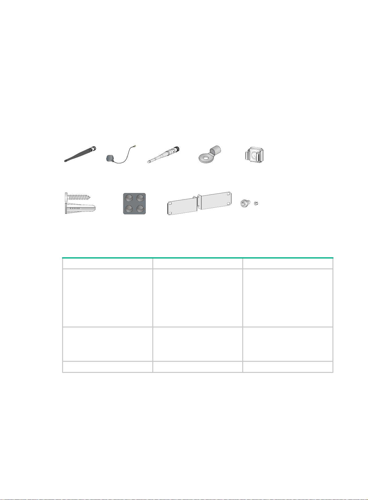
Installation accessories and tools
Installation accessories (RT-MSR810/RT-MSR810-W/RTMSR810-W-DB/RT-MSR810-LM/RT-MSR810-LM-CNDESJK/RT-MSR810-W-LM/RT-MSR810-10-PoE/RT-MSR810LM-HK/RT-MSR810-W-LM-HK/RT-MSR810-LM-GL/RTMSR810-W-LM-GL)
Figure 1 Installation accessories
4G antenna
Screw anchor and screw
(user supplied)
GPS antenna
(optional)
Rubber feet
WLAN antenna Ring terminal
Mounting brackets and screws (provided only with the
RT-MSR810-10-PoE and optional for other models)
Cage nut (user
supplied)
Table 5 Antenna compatibility
Model 4G antenna WLAN antenna
• RT-MSR810-LM
• RT-MSR810-LM-CNDE-SJK
• RT-MSR810-W-LM
• RT-MSR810-LM-HK
• RT-MSR810-W-LM-HK
• RT-MSR810-LM-GL
• RT-MSR810-W-LM-GL
• RT-MSR810-W
• RT-MSR810-W-LM
• RT-MSR810-W-LM-HK
• RT-MSR810-W-LM-GL
2 N/A
N/A 2
RT-MSR810-W-DB N/A 4
5
Page 13
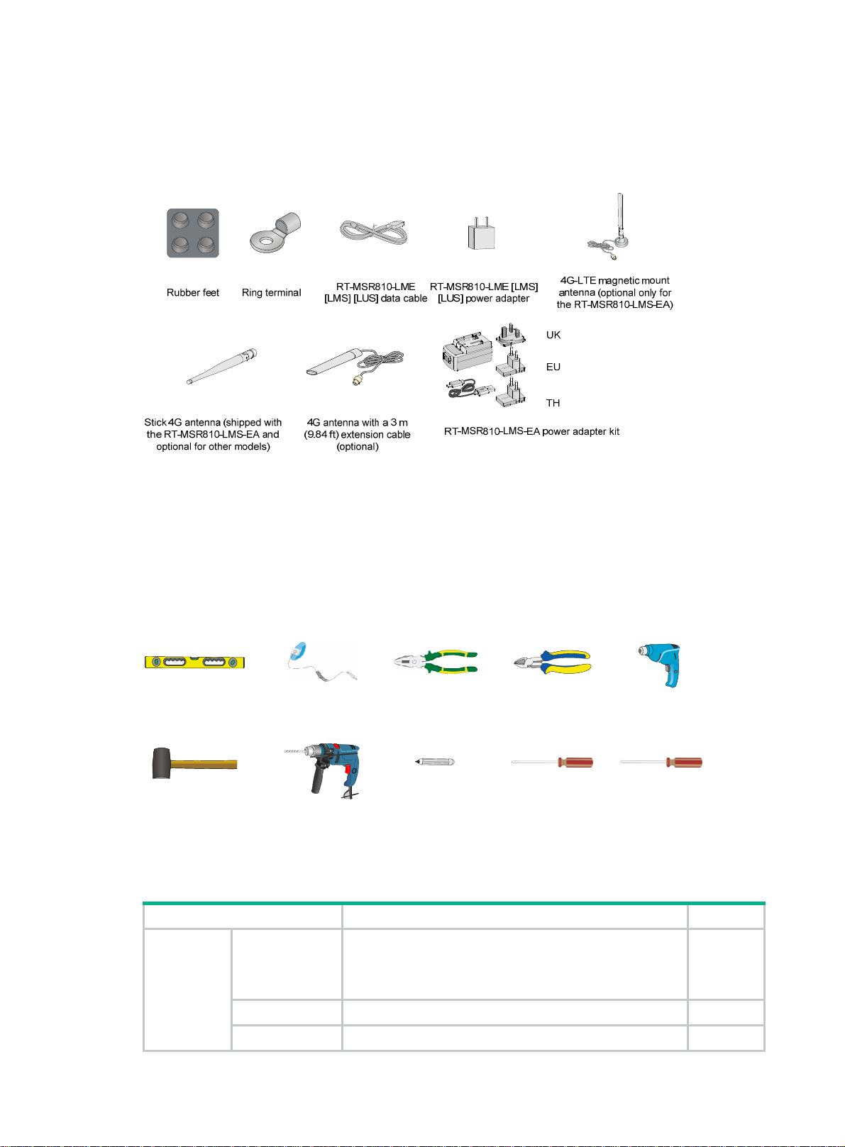
Installation accessories (RT-MSR810-LME/RT-MSR810LMS/RT-MSR810-LMS-EA/RT-MSR810-LUS)
Figure 2 Installation accessories
The RT-MSR810-LME, RT-MSR810-LMS, and RT-MSR810-LUS routers are not shipped with 4G
antennas.
Installation tools
No installation tools are provided with the router. Prepare them yourself as required.
Figure 3 Installation tools and equipment
Ruler Wire-stripping pliers
Rubber hammer
ESD wrist strap
Hammer drill Marker
Pre-installation checklist
Item Requirements Result
• There is a minimum clearance of 100 mm (3.94 in)
Ventilation
Installation
site
Temperature 0°C to 40°C (32°F to 104°F)
around the air inlet and outlet vents.
• An adequate ventilation system is available at the
installation site.
Diagonal pliers
Flathead screwdriver Phillips screwdriver
Heat gun
Relative
• 5% to 90% (noncondensing):
6
Page 14

Item Requirements Result
humidity { RT-MSR810
{ RT-MSR810-W
{ RT-MSR810-W-DB
{ RT-MSR810-LM
{ RT-MSR810-LM-CNDE-SJK
{ RT-MSR810-W-LM
{ RT-MSR810-10-PoE
{ RT-MSR810-LM-HK
{ RT-MSR810-W-LM-HK
{ RT-MSR810-LM-GL
{ RT-MSR810-W-LM-GL
• 0% to 95% (noncondensing):
{ RT-MSR810-LME
{ RT-MSR810-LMS
{ RT-MSR810-LMS-EA
{ RT-MSR810-LUS:
4
Cleanness
Dust concentration ≤ 3 × 10
on the tabletop over three days)
particles/m3 (no visible dust
• The router and floor are reliably grounded.
• The equipment room is dust-controlled.
ESD prevention
• Humidity and temperature are maintained at
acceptable levels.
• An ESD wrist strap is available.
• A single-phase three-wire power receptacle with
protection earth (PE) is available for filtering
interference from the power grid.
EMI prevention
• The router is far away from radio transmitting
stations, radar stations, and high-frequency devices.
• Electromagnetic shielding, for example, shielded
interface cables, is used as required.
• The router is reliably grounded.
• The power receptacle is reliably grounded.
Lightning
protection
• (Optional.) Port lightning protectors are available. A
signal lightning arrester is required at the input end of
an external signal cable.
• (Optional.) Power lightning protectors are available.
• A UPS is available.
Electricity safety
• The external power switch is located so to shut off
the power immediately when an accident occurs.
• The workbench is stable.
• The workbench is reliably grounded.
Safety
precautions
Tools
Reference
Workbench
• The router is far away from any sources of heat or moisture.
• The emergency power switch in the equipment room is identified and
accessible.
• Installation accessories supplied with the router are ready.
• User-supplied tools are ready.
• Documents shipped with the router are available.
• Online documents are available.
7
Page 15

Installing the router
WARNING!
To avoid injury, do not touch bare wires, terminals, or parts with high-voltage hazard signs.
IMPORTANT:
• The barcode on the router chassis contains product information that must be provided to local
sales agent when you return a faulty router for repair.
• Keep the tamper-proof seal on a mounting screw on the chassis cover intact, and if you want to
open the chassis, contact H3C for permission. Otherwise, H3C shall not be liable for any
consequence.
Installation prerequisites
• You have read "Preparing for installation" carefully.
• All requirements in "Preparing for installation" are me
t.
Installation flowchart
The following installation options are available for the router:
• Workbench mounting.
• Wall mounting.
• Rack mounting.
Determine the installation method according to the installation environment. Follow the installation
flowchart shown in Figure 4 to install the route
r.
8
Page 16
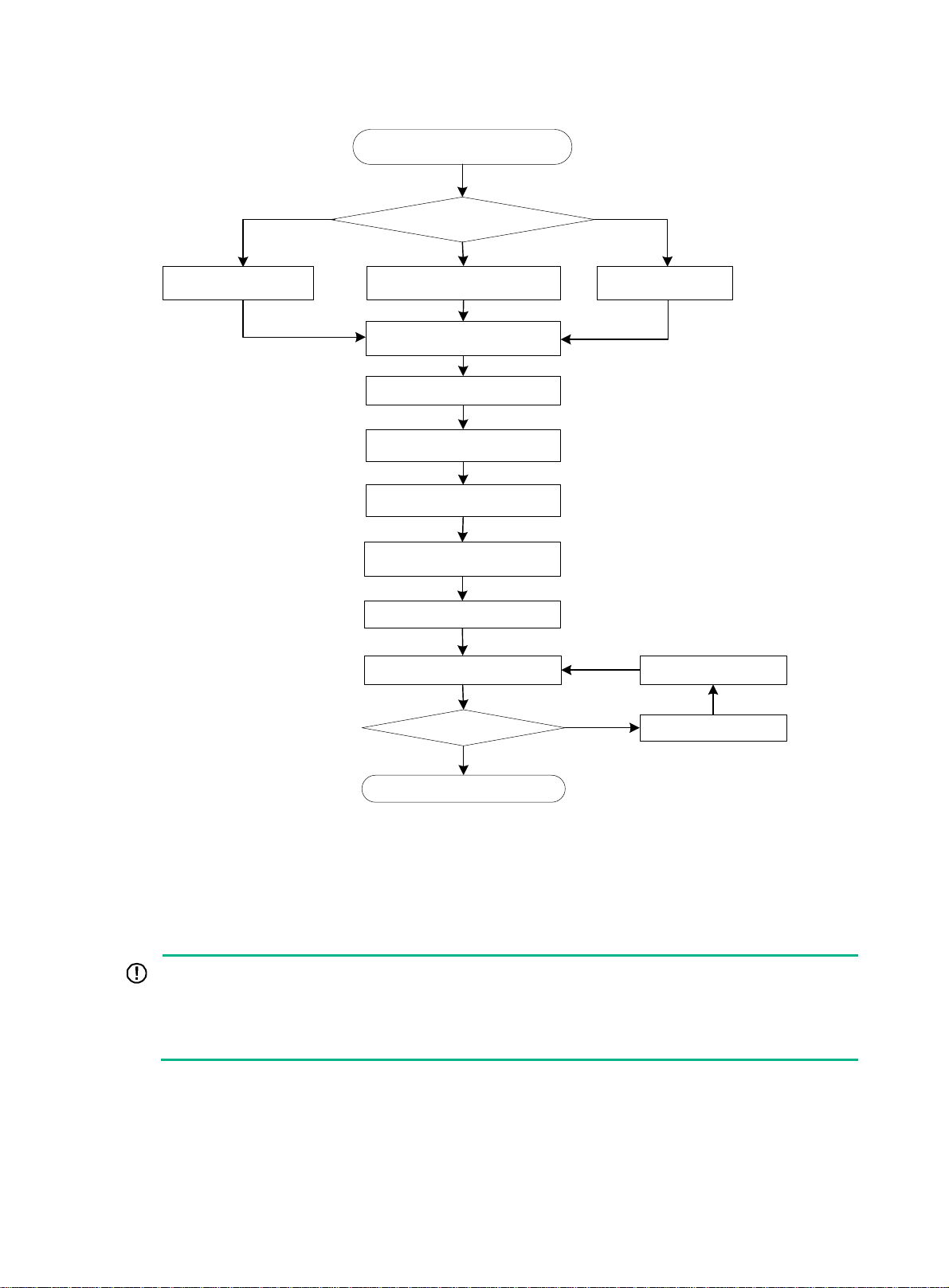
Figure 4 Installation flowchart
Start
Determine the
installation position
Mount the router on a
workbench
Mount the router in a rack
Connect the grounding cable
Install antennas
Connect interface cables
Connect the router to a
configuration terminal
Connect the power adapter or
power cord
Verify the installation
Power on the router
Operating correctly?
Yes
Mount the router on a
wall
Troubleshooting the
router
Power off the router
No
End
Installing the router
Mounting the router on a workbench
IMPORTANT:
• Make sure the workbench is clean, stable, and reliably grounded.
• Maintain a minimum clearance of 100 mm (3.94 in) around the router for heat dissipation.
• Do not place heavy objects on the router.
To mount the router on a workbench:
1. Place the router upside down on the workbench and attach the rubber feet to the four round
holes in the chassis bottom.
2. Place the router upside up on the workbench.
9
Page 17
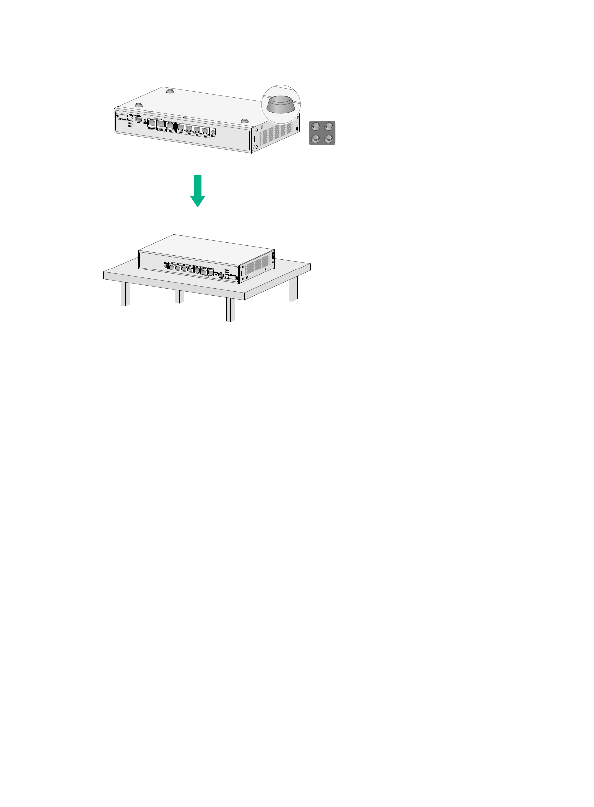
Figure 5 Mounting the router on a workbench
Mounting the router on a wall
Only the following routers support wall mounting:
• RT-MSR810
• RT-MSR810-LM
• RT-MSR810-LM-CNDE-SJK
• RT-MSR810-W-DB
• RT-MSR810-W
• RT-MSR810-W-LM
• RT-MSR810-LM-HK
• RT-MSR810-W-LM-HK
• RT-MSR810-LM-GL
• RT-MSR810-W-LM-GL
To mount the router on a wall:
1. Mark two screw hole locations on the wall. Make sure the two holes are 160 mm (6.30 in)
horizontally apart.
2. Drill holes with a minimum depth of 22 mm (0.87 in) in the marked locations.
3. Hammer an anchor into each hole until the anchor is flush with the wall.
4. Drive a screw into each anchor and make sure the screw protrudes a minimum of 1.5 mm
(0.06 in) from the wall.
5. Hang the router on the screws.
Position the router so the network interfaces face downwards, and the sides with ventilation
openings are perpendicular to the ground, as shown in Figure 6.
10
Page 18
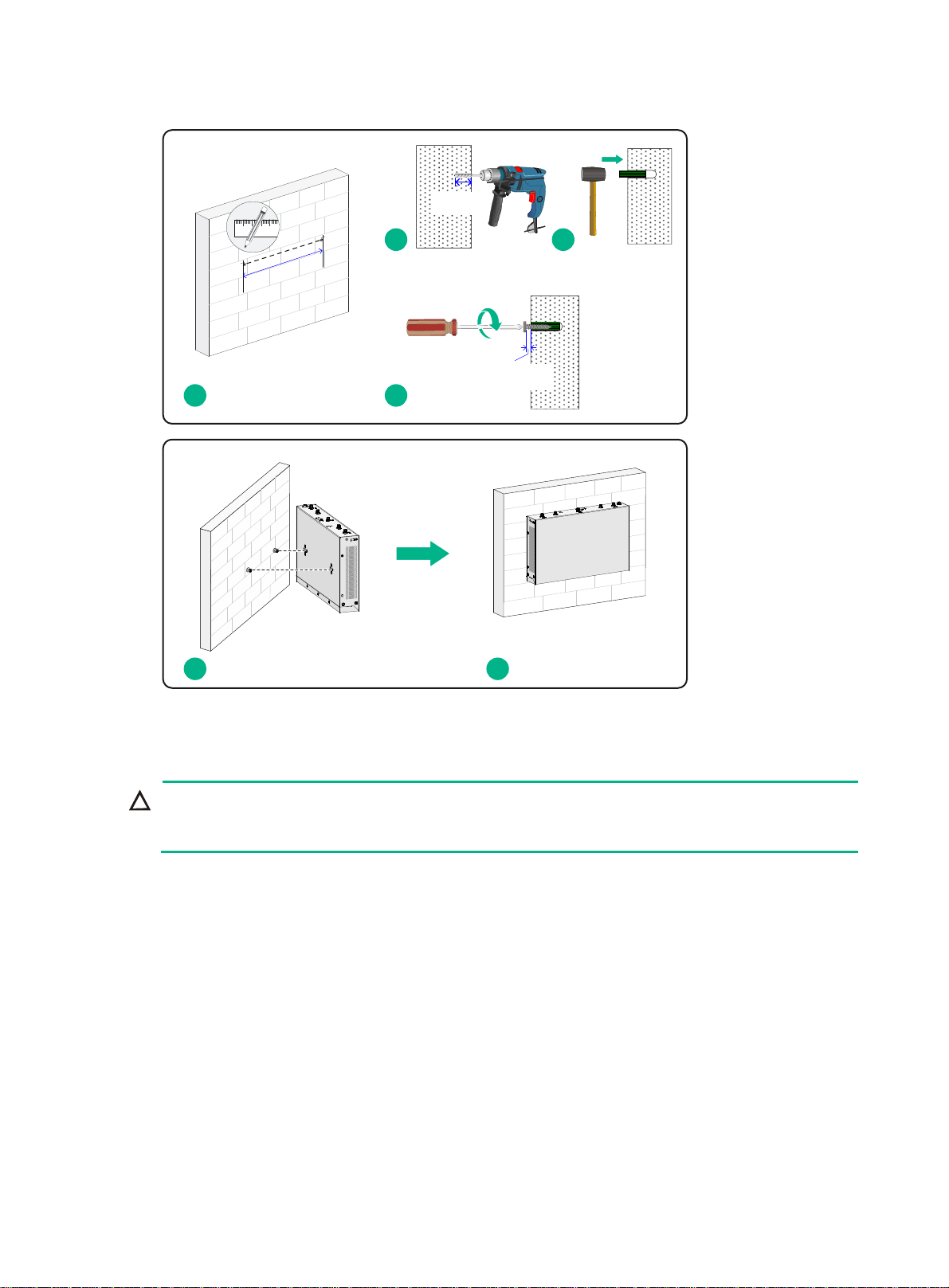
Figure 6 Wall-mounting the router
≥ 22 mm
(0.87 in)
2 3
)
n
i
0
3
6.
(
m
m
0
6
1
≥ 1.5 mm
1
4
(0.06 in)
5 6
Installing the router in a rack
CAUTION:
The mounting brackets can support only the weight of the router. Do not place objects on the
router.
Mounting brackets and screws are provided with the RT-MSR810-10-PoE and are optional for the
other models.
The RT-MSR810-LME, RT-MSR810-LMS, RT-MSR810-LMS-EA, and RT-MSR810-LUS routers do
not support rack mounting.
To install the router in a rack:
1. Use a mounting bracket to mark the cage nut installation holes in the front rack posts, as
shown in Figure 7.
Make
sure the cage nut installation holes on the front rack posts are on a horizontal line.
11
Page 19
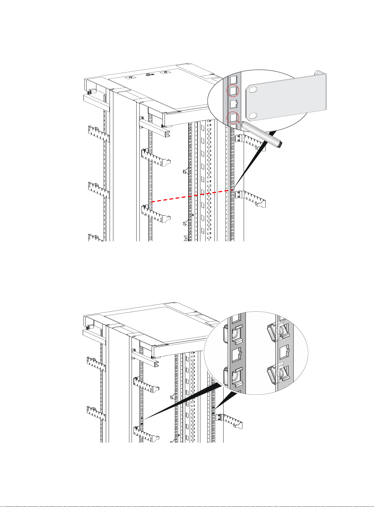
Figure 7 Marking cage nut installation holes
2. Install the cage nuts, as shown in Figure 8.
a. Insert one ear of a cage nut into the marked installation hole.
b. Use a flathead screwdriver to push another ear into the same hole.
Figure 8 Installing cage nuts
3. Attach mounting brackets to both sides of the router, as shown in Figure 9.
12
Page 20
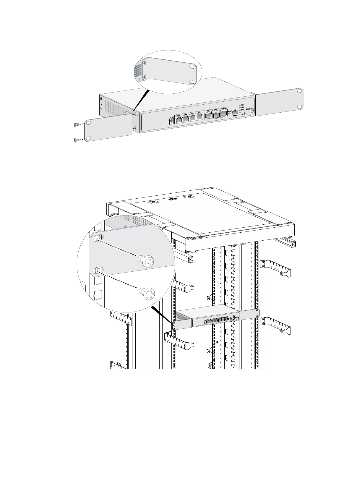
Figure 9 Attaching mounting brackets to the router
4. Use M6 screws to attach the mounting brackets on the router to the front rack posts, as
shown in Figure 10.
Figure 10
Securing the router to the rack
13
Page 21

Grounding the router
CAUTION:
• Correctly connecting the grounding cable is crucial to lightning protection and EMI protection.
When you install and use the router, first ground the router reliably.
• Ensure a minimum resistance of 5 ohms between the router and the ground.
The router provides only a ring terminal. No grounding cable is provided with the router. Purchase
a grounding cable yourself.
Attaching the grounding cable to the ring terminal
1. Cut the grounding cable to the desired length.
2. Use the wire-stripping pliers to peel 5 mm (0.20 in) of insulation sheath from one end of the
grounding cable.
3. Add a heat-shrink tubing on the cable.
4. Insert the bare metal part of the grounding cable into the ring terminal.
5. Use the needle-nose pliers to secure the metal part of the cable in the ring terminal.
6. Cover the joint with the heat-shrink tubing, and use a blow dryer to shrink the tubing around
the cable.
Figure 11 Attaching the grounding cable to the ring terminal
Grounding the router with a grounding strip
1. Remove the grounding screw from the grounding hole in the chassis.
14
Page 22

2. Use the grounding screw to attach the ring terminal of the grounding cable to the grounding
hole.
3. Use a screwdriver to fasten the grounding screw.
4. Connect the other end of the grounding cable to the grounding strip.
Figure 12 Connecting the grounding cable to the router
Grounding
screw
Grounding
hole
Grounding the router with a grounding conductor buried in the earth ground
If the installation site does not have any grounding strips, but earth ground is available, hammer a
0.5 m (1.64 ft) or longer angle iron or steel tube into the earth ground to serve as a grounding
conductor.
Weld the yellow-green grounding cable to the angel iron or steel tube and treat the joint for
corrosion protection.
Figure 13 Grounding the router with a grounding conductor buried in the earth ground
15
Page 23

Installing a 4G SIM card
CAUTION:
• Do not hot-swap a 4G SIM card.
• To avoid damaging the SIM card slot, do not use excessive force when installing a 4G SIM
card.
• To avoid slot damage, make sure the SIM card is flush with the card tray when a SIM card tray
is used.
The RT-MSR810-LM, RT-MSR810-LM-CNDE-SJK, RT-MSR810-W-LM, RT-MSR810-LM-HK, RTMSR810-W-LM-HK, RT-MSR810-LM-GL, and RT-MSR810-W-LM-GL routers support standard
SIM cards.
The RT-MSR810-LME, RT-MSR810-LMS, RT-MSR810-LMS-EA, and RT-MSR810-LUS routers
support Micro SIM cards and provide two SIM card slots. SIM0 (M) is the master slot and SIM1 (S)
is the standby slot. Only one slot is active at a time. As a best practice, use the master slot if you
are to install only one SIM card. You can use the
slot. For more information about the command, see Layer 2—WAN Access Command Reference
in H3C MSR810[2600][3600] Comware 7 Command References.
To install a 4G SIM card:
1. Remove the screw on the 4G SIM card slot cover and take off the cover.
2. Insert the 4G SIM card into the SIM card slot along the guide rails.
3. Reinstall the cover and fasten the screw on the cover.
sim switch-to command to specify the active
Figure 14 Installing a 4G SIM card (RT-MSR810-LMS/RT-MSR810-LUS)
Installing a Micro SD card
CAUTION:
To avoid damaging the Micro SD card slot, do not use excessive force when you install a Micro SD
card.
Only the following routers support Micro SD cards:
• RT-MSR810
• RT-MSR810-LM
• RT-MSR810-LM-CNDE-SJK
16
Page 24

• RT-MSR810-W-DB
• RT-MSR810-W
• RT-MSR810-W-LM
• RT-MSR810-LM-HK
• RT-MSR810-W-LM-HK
• RT-MSR810-LM-GL
• RT-MSR810-W-LM-GL
To install a Micro SD card:
1. Remove the screw on the Micro SD card slot cover and take off the cover.
2. Insert the Micro SD card into the Micro SD card slot along the guide rails.
3. Reinstall the cover and fasten the screw on the cover.
Figure 15 Installing a Micro SD card
Installing an SD card
CAUTION:
• To avoid damaging the SD card slot, do not use excessive force when you install an SD card.
• The router cannot read data from or write data into a SD card if the SD card is in write
protection state.
Only the RT-MSR810-10-PoE router supports SD cards.
To install an SD card:
1. Remove the screw on the SD card slot cover and take off the cover.
2. Insert the SD card into the SD card slot along the guide rails.
3. Reinstall the cover and fasten the screw on the cover.
17
Page 25

Figure 16 Installing an SD card
1
Installing a 4G antenna
Only the following routers support 4G antennas:
• RT-MSR810-LM
• RT-MSR810-LM-CNDE-SJK
• RT-MSR810-W-LM
• RT-MSR810-LM-HK
• RT-MSR810-W-LM-HK
• RT-MSR810-LM-GL
• RT-MSR810-W-LM-GL
• RT-MSR810-LME
• RT-MSR810-LMS
• RT-MSR810-LMS-EA
• RT-MSR810-LUS
2
3
No 4G antenna is provided with the RT-MSR810-LME, RT-MSR810-LMS, and RT-MSR810-LUS
routers. Purchase one yourself if required.
To install a 4G antenna:
1. Change the angle of the antenna orientation from vertical to horizontal.
2. Attach the 4G antenna to the 4G antenna port on the router. Do not over-tighten the antenna
to avoid damage.
For better signal receiving, change the antenna orientation to vertical.
18
Page 26

Figure 17 Installing 4G antennas
Installing a WLAN antenna
Only the following routers support WLAN antennas:
• RT-MSR810-W
• RT-MSR810-W-LM
• RT-MSR810-W-DB
• RT-MSR810-W-LM-HK
• RT-MSR810-W-LM-GL
You can install two WLAN antennas for the RT-MSR810-W, RT-MSR810-W-LM, RT-MSR810-WLM-HK, and RT-MSR810-W-LM-GL routers and four WLAN antennas for the RT-MSR810-W-DB
router.
To install a WLAN antenna:
1. Change the angle of the antenna orientation from vertical to horizontal.
2. Attach the antenna to the WLAN antenna port on the router. Do not over-tighten the antenna
to avoid damage.
For better signal receiving, change the antenna orientation to vertical.
19
Page 27

Figure 18 Installing WLAN antennas
Installing a GPS antenna
Only the routers support a GPS antenna:
• RT-MSR810-LM
• RT-MSR810-LM-CNDE-SJK
• RT-MSR810-W-LM
• RT-MSR810-LM-HK
• RT-MSR810-W-LM-HK
• RT-MSR810-LM-GL
• RT-MSR810-W-LM-GL
To install a GPS antenna:
1. Attach the male connector of the GPS antenna to the GPS antenna port on the router.
Do not use excessive force to avoid antenna damage.
2. Attach the magnetic antenna radome to a metal surface.
20
Page 28

Figure 19 Installing a GPS antenna
Supplying power to a terminal through PoE
Only the RT-MSR810-10-PoE router supports PoE. To supply power to a terminal, the terminal
must support PoE.
To supply power to a terminal through PoE:
1. Connect one end of the cable to an Ethernet port on the router.
2. Connect the other end of the cable to the Ethernet port on a terminal.
3. Examine the port LEDs on the router. For more information about the LEDs, see "LED
ption."
descri
21
Page 29

Figure 20 Supplying power to a terminal
Connecting Ethernet interface cables
1. Connect one end of the cable to an Ethernet port on the router.
2. Connect the other end of the cable to the Ethernet port on a host.
3. Examine the port LEDs on the router. For more information about the LEDs, see "LED
ption."
descri
Figure 21 Connecting an Ethernet cable
22
Page 30

Connecting the console cable and setting terminal parameters
Connecting the console cable
CAUTION:
The serial ports on PCs do not support hot swapping. To connect a PC to an operating router, first
connect the PC end. To disconnect a PC from an operating router, first disconnect the router end.
To connect the console cable:
1. Select a configuration terminal, which can be an ASCII terminal with an RS-232 serial port or
a PC. (A PC is more commonly used.)
2. Connect the DB-9 connector (female) of the console cable to the RS-232 serial port on the
configuration terminal and the RJ-45 connector to the console port of the router.
Figure 22 Connecting the console cable
Setting configuration terminal parameters
To access the device from the console port, you must run a terminal emulator program
(HyperTerminal, PuTTY, or Tera Term) on the configuration terminal. For information about using a
terminal emulator program, see the program's user guide.
The following are the required terminal settings:
• Baud rate—9600.
• Data bits—8.
• Stop bits—1.
• Parity—None.
• Flow control—None.
23
Page 31

Connecting the power adapter or power cord
CAUTION:
The power adapter kit provided with the RT-MSR810-LMS-EA router includes UK, EU, and TH
power plugs. Use a power plug that follows the standards of the country or region to assemble the
power adapter.
The following routers require a power adapter:
• RT-MSR810
• RT-MSR810-LM
• RT-MSR810-LM-CNDE-SJK
• RT-MSR810-W-DB
• RT-MSR810-W
• RT-MSR810-W-LM
• RT-MSR810-LM-HK
• RT-MSR810-W-LM-HK
• RT-MSR810-LM-GL
• RT-MSR810-W-LM-GL
• RT-MSR810-LME
• RT-MSR810-LMS
• RT-MSR810-LMS-EA
• RT-MSR810-LUS
The RT-MSR810-10-PoE router uses a power cord.
Connecting the power adapter
CAUTION:
To avoid power adapter damage, use the power adapter provided with the router.
To connect the power adapter:
1. Make sure the router is reliably grounded.
2. Connect the power adapter to the AC receptacle.
3. Connect the DC output plug of the power adapter to the power adapter receptacle on the
router.
24
Page 32

Figure 23 Connecting the power adapter (RT-MSR810/MSR810-LM/RT-MSR810-LM-CNDESJK/RT-MSR810-W-DB/RT-MSR810-W/RT-MSR810-W-LM/RT-MSR810-LM-HK/RT-MSR810-WLM-HK/RT-MSR810-LM-GL/RT-MSR810-W-LM-GL)
Figure 24 Assembling the RT-MSR810-LMS-EA adapter
Figure 25 Connecting the power adapter (RT-MSR810-LME/RT-MSR810-LMS/RT-MSR810LMS-EA/RT-MSR810-LUS)
25
Page 33

Connecting the power cord
1. Make sure the router is reliably grounded.
2. Connect the power cord to the AC receptacle.
3. Insert the AC output plug of the power cord to the power adapter receptacle on the router.
Figure 26 Connecting the power cord for the RT-MSR810-10-PoE
Verifying the installation
After you complete the installation, verify the following information:
• There is enough space around the router for heat dissipation.
• The router is securely installed.
• Antennas and USB devices are installed correctly.
• The router and power source are reliably grounded.
• The power source is as required by the router.
• The router is connected correctly to the configuration terminal and other devices. Parameters
are configured correctly on the configuration terminal.
Accessing the router for the first time
WARNING!
Before powering on the router, locate the switch for the power source so that you can cut off power
promptly in case of an emergency.
For a router starting with empty configuration, you must press Ctrl+D to access the CLI.
To access the router for the first time:
1. Verify that the installation and configuration environment is as described in "Verifying the
installation."
2. Powe
3. During the booting process, verify the following items:
r on the router.
{ The LEDs on the front panel indicate normal operation. See "LED description."
{ The configuration terminal displays information correctly.
The router first initializes its memory at startup and then runs BootWare.
System is starting...
26
Page 34

Press Ctrl+D to access BASIC-BOOTWARE MENU
Booting Normal Extend BootWare
Do you want to check SDRAM? [Y/N]
****************************************************************************
* *
* H3C MSR810 BootWare, Version 1.03 *
* *
****************************************************************************
Copyright (c) 2004-2018 New H3C Technologies Co., Ltd.
Compiled Date : Mar 20 2018
CPU ID : 0xa
CPU L1 Cache : 32KB
CPU L2 Cache : 256KB
Memory Type : DDR3 SDRAM
Memory Size : 1024MB
Memory Speed : 533MHz
Flash Size : 256MB
PCB Version : 2.0
BootWare Validating...
Press Ctrl+B to access EXTENDED-BOOTWARE MENU...
Loading the main image files...
Loading file flash:/msr810-cmw710-system-e030401.bin........................
........................Done.
Loading file flash:/msr810-cmw710-security-e030401.bin...Done.
Loading file flash:/msr810-cmw710-voice-e030401.bin...Done.
Loading file flash:/msr810-cmw710-data-e030401.bin......Done.
Loading file flash:/msr810-cmw710-wifidog-e030401.bin...Done.
Loading file flash:/msr810-cmw710-boot-e030401.bin.........Done.
Image file flash:/msr810-cmw710-boot-e030401.bin is self-decompressing......
............................................................................
............................................................................
............................................................................
............................................................................
............................................................................
............................................................................
............................................................................
..............................................Done.
System image is starting...
Cryptographic Algorithms Known-Answer Tests are running ...
CPU 0 of slot 0 in chassis 0:
Starting Known-Answer tests in the user space.
……
Cryptographic Algorithms Known-Answer Tests passed.
27
Page 35

Startup configuration file does not exist.
Performing automatic configuration... Press CTRL_D to break.
Line con0 is available.
Press ENTER to get started.
4. Press Enter. The router is ready to configure when you see the following prompt:
<Sysname>
5. Configure basic settings for the router.
For information about configuring basic setting for the router, see Fundamental s Configuration
Guide in H3C MSR810[2600][3600] Router Series Comware 7 Configuration Guides and
Fundamentals Command Reference in H3C MSR810[2600][3600] Router Series Comware 7
Command References.
28
Page 36

Troubleshooting
IMPORTANT:
• The barcode on the router chassis contains product information that must be provided to local
sales agent when you return a faulty router for repair.
• Keep the tamper-proof seal on a mounting screw on the chassis cover intact, and if you want to
open the chassis, contact H3C for permission. Otherwise, H3C shall not be liable for any
consequence.
Power module failure
Symptom
The router cannot be powered on and the LEDs on the front panel are off.
Solution
To resolve the issue:
1. Verify that the power cord connects the router to the power source correctly.
2. Verify that the power source is operating correctly.
3. Verify that the power cord is in good condition.
4. If the issue persists, contact H3C Support.
No display on the configuration terminal
Symptom
The configuration terminal does not have display when the router is powered on.
Solution
To resolve the issue:
1. Verify that the power system is operating correctly.
2. Verify that the console cable is connected correctly to the specified serial port on the
configuration terminal.
3. Verify that the following settings are configured for the terminal:
{ Baud rate—9,600.
{ Data bits—8.
{ Parity—none.
{ Stop bits—1.
{ Flow control—none.
{ Emulation—VT100.
4. Verify that the console cable is in good condition.
5. If the issue persists, contact H3C Support.
29
Page 37

Garbled display on the configuration terminal
Symptom
The configuration terminal has garbled display when the router is powered on.
Solution
To resolve the issue:
1. Verify that the following settings are configured for the terminal:
{ Baud rate—9,600.
{ Data bits—8.
{ Parity—None.
{ Stop bits—1.
{ Flow control—None.
2. If the issue persists, contact H3C Support.
No response from the serial port
Symptom
The serial port on the router does not respond
Solution
To resolve the issue:
1. Verify that the serial cable is in good condition and the serial port settings are correct.
2. If the issue persists, contact H3C Support.
3G/4G SIM card and 4G antenna failures
Symptom
After a 3G/4G SIM card and 4G antennas are installed on the router and the router is powered on,
the corresponding LEDs on the front panel indicate operation failure.
Solution
To resolve the issue:
1. Verify that the 3G/4G SIM card has been correctly installed and makes good contact with the
card socket.
2. Verify that the 3G/4G SIM card and the card socket use the same wireless standard.
3. Verify that the 4G antenna is correctly installed.
4. Verify that the 3G/4G SIM card, card socket, and 4G antenna are in good condition.
5. Verify that the network provided by NSP is running correctly.
6. If the issue persists, contact H3C Support.
30
Page 38

Restoring the factory settings
Scenario 1
Symptom
When you replace the router, the router password is lost. As a result, you cannot log in to the
router and do not know the router configuration.
Solution
Because the router is replaced, you do not need to save the configuration of the router. In this case,
you can press the RESET button for more than 4 seconds to reboot the router and restore the
factory settings. Then, you can use the username and password shipped with the router to log in to
the router.
When the router configuration must be saved and you have a console cable, you can log in to the
router from the BootWare menu.
Scenario 2
Symptom
After the configuration is modified, the network connectivity is lost. When you check the
configuration, the configuration is very complicated and it is hard to locate the errors. In this case,
you must configure the router again.
Solution
If you have not saved any configuration, you can reboot the router by pressing the RESET button
for a short time or power off the router.
If you have saved the configuration, delete the configuration file at the CLI, and press the RESET
button to restore the factory settings.
Scenario 3
Symptom
The router crashes.
Solution
Press the RESET button for a short time to reboot the router.
Reset button usage guidelines
The router provides the RESET button. You can use the button to reboot the system or restore the
factory settings.
• Press the RESET button for a short time to reboot the router.
• Press the RESET button for more than 4 seconds to reboot the router and restore the factory
settings.
31
Page 39

Appendix A Chassis views and technical specifications
Chassis views
The figures in this appendix are for illustration only.
RT-MSR810
Figure 27 Front view
(1) Power adapter receptacle (2) Gigabit Ethernet LAN ports (GE1 to GE4)
(3) Gigabit Ethernet WAN port (GE0) (4) Gigabit fiber port (SFP5)
(5) Console port (6) USB port 0
(7) Micro SD card slot (8) USB port 1
(9) Reset button (RESET)
Figure 28 Rear view
(1) Grounding screw
32
Page 40

RT-MSR810-W
Figure 29 Front view
(1) Power adapter receptacle (2) Gigabit Ethernet LAN ports (GE1 to GE4)
(3) Gigabit Ethernet WAN port (GE0) (4) Gigabit fiber port (SFP5)
(5) Console port (6) USB port 0
(7) Micro SD card slot (8) USB port 1
(9) Reset button (RESET)
Figure 30 Rear view
1 2 3 4 5 6
789
(1) Grounding screw (2) 2.4G WLAN antenna port
(3) 2.4 G WLAN antenna port
33
Page 41

RT-MSR810-W-DB
Figure 31 Front view
(1) Power adapter receptacle (2) Gigabit Ethernet LAN ports (GE1 to GE4)
(3) Gigabit Ethernet WAN ports (GE0) (4) Gigabit fiber port (SFP5)
(5) Console port (6) USB port 0
(7) Micro SD card slot (8) USB port 1
(9) Reset button (RESET)
Figure 32 Rear view
(1) Grounding screw (2) 2.4G WLAN antenna port 1
(3) 5G WLAN antenna port 1 (4) 5G WLAN antenna port 2
(5) 2.4G WLAN antenna port 2
34
Page 42

RT-MSR810-LM
Figure 33 Front view
(1) Power adapter receptacle (2) Gigabit Ethernet LAN ports (GE1 to GE4)
(3) Gigabit Ethernet WAN port (GE0) (4) Gigabit fiber port (SFP5)
(5) Console port (6) USB port
(7) Micro SD card slot (8) Reset button (RESET)
Figure 34 Rear view
1 2 3 4 5 6
78
(1) Grounding screw (2) LTE antenna port 1
(3) 4G SIM card slot (4) GPS antenna port
(5) LTE antenna port 2
35
Page 43

RT-MSR810-LM-CNDE-SJK
Figure 35 Front view
1 2 3 4 5 6
(1) Power adapter receptacle (2) Gigabit Ethernet LAN ports (GE1 to GE4)
(3) Gigabit Ethernet WAN port (GE0) (4) Gigabit fiber port (SFP5)
(5) Console port (6) USB port
(7) Micro SD card slot (8) Reset button (RESET)
Figure 36 Rear view
78
(1) Grounding screw (2) LTE antenna port 1
(3) 4G SIM card slot (4) GPS antenna port
(5) LTE antenna port 2
36
Page 44

RT-MSR810-W-LM
Figure 37 Front view
1 2 3 4 5 6
(1) Power adapter receptacle (2) Gigabit Ethernet LAN ports (GE1 to GE4)
(3) Gigabit Ethernet WAN port (GE0) (4) Gigabit fiber port (SFP5)
(5) Console port (6) USB port
(7) Micro SD card slot (8) Reset button (RESET)
Figure 38 Rear view
78
(1) Grounding screw (2) LTE antenna port 1
(3) 2.4G WLAN antenna port (4) 4G SIM card slot
(5) GPS antenna port (6) 2.4G WLAN antenna port
(7) LTE antenna port 2
37
Page 45

RT-MSR810-10-PoE
Figure 39 Front view
(1) Gigabit Ethernet LAN ports (GE2 to GE9) (2) Gigabit Ethernet WAN port (GE0)
(3) Gigabit combo interface (GE1/SFP1) (4) Console port
(5) Reset button (RESET) (6) USB port
(7) SD card slot
Figure 40 Rear view
1 2 3
(1) AC power receptacle (2) Grounding screw
(3) Security slot
RT-MSR810-LM-HK
Figure 41 Front view
1 2 3 4 5 6
(1) Power adapter receptacle (2) Gigabit Ethernet LAN ports (GE1 to GE4)
(3) Gigabit Ethernet WAN port (GE0) (4) Gigabit fiber port (SFP5)
(5) Console port (6) USB port
(7) Micro SD card slot (8) Reset button (RESET)
78
38
Page 46

Figure 42 Rear view
(1) Grounding screw (2) LTE antenna port 1
(3) 4G SIM card slot (4) GPS antenna port
(5) LTE antenna port 2
RT-MSR810-W-LM-HK
Figure 43 Front view
1 2 3 4 5 6
78
(1) Power adapter receptacle (2) Gigabit Ethernet LAN ports (GE1 to GE4)
(3) Gigabit Ethernet WAN port (GE0) (4) Gigabit fiber port (SFP5)
(5) Console port (6) USB port
(7) Micro SD card slot (8) Reset button (RESET)
Figure 44 Rear view
(1) Grounding screw (2) LTE antenna port 1
(3) 2.4G WLAN antenna port (4) 4G SIM card slot
(5) GPS antenna port (6) 2.4G WLAN antenna port
(7) LTE antenna port 2
39
Page 47

RT-MSR810-LM-GL
Figure 45 Front view
1 2 3 4 5 6
(1) Power adapter receptacle (2) Gigabit Ethernet LAN ports (GE1 to GE4)
(3) Gigabit Ethernet WAN port (GE0) (4) Gigabit fiber port (SFP5)
(5) Console port (6) USB port
(7) Micro SD card slot (8) Reset button (RESET)
Figure 46 Rear view
78
(1) Grounding screw (2) LTE antenna port 1
(3) 4G SIM card slot (4) GPS antenna port
(5) LTE antenna port 2
40
Page 48

RT-MSR810-W-LM-GL
Figure 47 Front view
1 2 3 4 5 6
(1) Power adapter receptacle (2) Gigabit Ethernet LAN ports (GE1 to GE4)
(3) Gigabit Ethernet WAN port (GE0) (4) Gigabit fiber port (SFP5)
(5) Console port (6) USB port
(7) Micro SD card slot (8) Reset button (RESET)
Figure 48 Rear view
78
(1) Grounding screw (2) LTE antenna port 1
(3) 2.4G WLAN antenna port (4) 4G SIM card slot
(5) GPS antenna port (6) 2.4G WLAN antenna port
(7) LTE antenna port 2
41
Page 49

RT-MSR810-LME
Figure 49 Front view
(1) LTE antenna port (2) DC power receptacle
(3) USB port (4) Reset button (RESET)
(5) Megabit Ethernet ports (FE0 to FE3)
Figure 50 Rear view
(1) Console port (2) 4G SIM card slots (SIM0 and SIM1)
(3) Grounding screw
RT-MSR810-LMS-EA/RT-MSR810-LMS/RT-MSR810-LUS
Figure 51 Front view
(1) LTE antenna port 0 (2) GPS antenna port (reserved for future use)
(3) LTE antenna port 1 (4) USB port
(5) DC power receptacle (6) Reset button (RESET)
(7) Fast Ethernet ports (FE0 to FE3)
42
Page 50

Figure 52 Rear view
(1) Console port (2) Grounding screw
(3) 4G SIM card slots (SIM0 and SIM1)
Technical specifications
Table 6 Technical specifications (1)
Item RT-MSR810 RT-MSR810-W RT-MSR810-W-DB RT-MSR810-10-PoE
Console port 1 1 1 1
USB port 2 2 2 1
GE WAN port 1 1 1
GE SFP port 1 1 1 1 (combo fiber port)
GE LAN port 4 4 4 8
FE port N/A N/A N/A N/A
Micro SD card
slot
SD card slot N/A N/A N/A 1
Built-in 3G/4G
module
LTE antenna
port
WLAN antenna
port
GPS antenna
port
Memory 1 GB DDR3 1 GB DDR3 1 GB DDR3 1 GB DDR3
Flash 256 MB 256 MB 256 MB 256 MB
1 1 1 N/A
N/A N/A N/A N/A
N/A N/A N/A N/A
N/A 2 4 N/A
N/A N/A N/A N/A
2 (one combo copper
port)
Dimensions (H
× W × D)
(excluding
rubber feet and
mounting
brackets)
43.6 × 266 ×
161 mm (1.72
× 10.47 × 6.34
in)
43.6 × 266 × 161
mm (1.72 × 10.47
× 6.34 in)
43
43.6 × 266 × 161 mm
(1.72 × 10.47 × 6.34
in)
44.2 × 330 × 230 mm
(1.74 × 12.99 × 9.06 in)
Page 51

Item RT-MSR810 RT-MSR810-W RT-MSR810-W-DB RT-MSR810-10-PoE
100 VAC to
Input voltage
Power rating 24 W 24 W 24 W 20 W
PoE power N/A N/A N/A 65 W
240 VAC @
50 to 60Hz
100 VAC to 240
VAC @ 50 to
60Hz
100 VAC to 240 VAC
@ 50 to 60Hz
100 VAC to 240 VAC
@ 50 to 60Hz
Operating
temperature
Operating
humidity
0°C to 40°C (32°F to 104°F)
5% RH to 90% RH, non-condensing
Table 7 Technical specifications (2)
Item
Console port 1 1 1 1 1
USB port 1 1 1 1 1
GE WAN port 1 1 1 1 1
GE SFP port 1 1 1 1 1
GE LAN port 4 4 4 4 4
FE port N/A N/A N/A N/A N/A
Micro SD card
slot
Built-in 3G/4G
module
RT-MSR810LM
1 1 1 1 1
TDD-LTE, FDDLTE, TDSCDMA,
WCDMA,
EVDO,
CDMA1x, and
GSM
RT-MSR810LM-CNDESJK
TDD-LTE,
FDD-LTE, TDSCDMA,
WCDMA,
EVDO,
CDMA1x, and
GSM
RT-MSR810W-LM
TDD-LTE,
FDD-LTE, TDSCDMA,
WCDMA,
EVDO,
CDMA1x, and
GSM
RT-MSR810LM-HK
LTE, UMTS
(WCDMA),
HSDPA,
HSUPA,
HSPA+, DCHSPA+, GSM,
GPRS, EDGE,
and GNSS
RT-MSR810W-LM-HK
LTE, UMTS
(WCDMA),
HSDPA,
HSUPA,
HSPA+, DCHSPA+, GSM,
GPRS, EDGE,
and GNSS
LTE antenna
port
WLAN
antenna port
GPS antenna
port
Memory 1 GB DDR3 1 GB DDR3 1 GB DDR3 1 GB DDR3 1 GB DDR3
Flash 256 MB 256 MB 256 MB 256 MB 256 MB
2 2 2 2 2
N/A N/A 2 N/A 2
1 1 1 1 1
44
Page 52

Item
Dimensions
(H × W × D)
(excluding
rubber feet
and mounting
brackets)
Input voltage
Rated power 24 W 24 W 24 W 24 W 24 W
PoE power N/A N/A N/A N/A N/A
Operating
temperature
Operating
humidity
RT-MSR810LM
43.6 × 266 ×
161 mm (1.72 ×
10.47 × 6.34 in)
100 VAC to 240
VAC @ 50 to
60Hz
0°C to 40°C (32°F to 104°F)
5% RH to 90% RH, non-condensing
RT-MSR810LM-CNDESJK
43.6 × 266 ×
161 mm (1.72
× 10.47 × 6.34
in)
100 VAC to
240 VAC @
50 to 60Hz
RT-MSR810W-LM
43.6 × 266 ×
161 mm (1.72
× 10.47 × 6.34
in)
100 VAC to
240 VAC @
50 to 60Hz
RT-MSR810LM-HK
43.6 × 266 ×
161 mm (1.72
× 10.47 × 6.34
in)
100 VAC to
240 VAC @
50 to 60Hz
RT-MSR810W-LM-HK
43.6 × 266 ×
161 mm (1.72 ×
10.47 × 6.34 in)
100 VAC to 240
VAC @ 50 to
60Hz
Table 8 Technical specifications (3)
Item RT-MSR810-LME RT-MSR810-LMS
Console port 1 1 1 1
USB port 1 1 1 1
GE WAN port N/A N/A N/A N/A
GE SFP port N/A N/A N/A N/A
GE LAN port N/A N/A N/A N/A
FE port 4 4 4 4
Micro SD card
slot
Built-in 3G/4G
module
N/A N/A N/A N/A
TDD-LTE, FDDLTE, TD-SCDMA,
UMTS, GSM,
EVDO, CDMA1x,
TDD-LTE, FDDLTE, TD-SCDMA,
UMTS, and GSM
TDD-LTE, FDDLTE, TD-SCDMA,
UMTS, GSM,
EVDO, CDMA1x,
TDD-LTE, FDDLTE, TD-SCDMA,
UMTS, and GSM
RT-MSR810LMS-EA
TDD-LTE, FDDLTE, UMTS, and
GSM
RT-MSR810-LUS
TDD-LTE, FDDLTE, TD-SCDMA,
UMTS, and GSM
LTE antenna
port
1 2 2 2
45
Page 53

Item RT-MSR810-LME RT-MSR810-LMS
WLAN
antenna port
GPS antenna
port
Memory 1 GB DDR3 512 MB DDR3 1 GB DDR3 512 MB DDR3
Flash 256 MB 256 MB 256 MB 256 MB
Dimensions
(H × W × D)
(excluding
rubber feet
and mounting
brackets)
Input voltage
N/A N/A N/A N/A
N/A Reserved Reserved Reserved
35 × 115 × 100 mm
(1.38 × 4.53 × 3.94
in)
100 VAC to 240
VAC @ 50 to 60Hz
35 × 115 × 100 mm
(1.38 × 4.53 × 3.94
in)
100 VAC to 240
VAC @ 50 to 60Hz
RT-MSR810LMS-EA
35 × 115 × 100 mm
(1.38 × 4.53 × 3.94
in)
100 VAC to 240
VAC @ 50 to 60Hz
RT-MSR810-LUS
35 × 115 × 100 mm
(1.38 × 4.53 × 3.94
in)
100 VAC to 240
VAC @ 50 to 60Hz
Power rating 10 W 10 W 10 W 10 W
PoE power N/A N/A N/A N/A
Operating
temperature
Operating
humidity
0°C to 40°C (32°F to 104°F)
0% RH to 95% RH, non-condensing
Table 9 Technical specifications (4)
Item RT-MSR810-LM-GL RT-MSR810-W-LM-GL
Console port 1 1
USB port 1 1
GE WAN port 1 1
GE SFP port 1 1
GE LAN port 4 4
FE port N/A N/A
Micro SD card
slot
Built-in 3G/4G
module
1 1
LTE, UMTS (WCDMA), HSDPA, HSUPA,
HSPA+, DC-HSPA+, GSM, GPRS,
EDGE, and GNSS
46
LTE, UMTS (WCDMA), HSDPA, HSUPA,
HSPA+, DC-HSPA+, GSM, GPRS,
EDGE, and GNSS
Page 54

Item RT-MSR810-LM-GL RT-MSR810-W-LM-GL
4G LET antenna
port
WLAN antenna
port
2 2
N/A 2
GPS antenna port 1 1
Memory 1 GB DDR3 1 GB DDR3
Flash 256 MB 256 MB
Dimensions (H ×
W × D) (excluding
rubber feet and
mounting
43.6 × 266 × 161 mm (1.72 × 10.47 ×
6.34 in)
43.6 × 266 × 161 mm (1.72 × 10.47 ×
6.34 in)
brackets)
Input voltage 100 VAC to 240 VAC @ 50 to 60Hz 100 VAC to 240 VAC @ 50 to 60Hz
Power rating 24 W 24 W
PoE power N/A N/A
Operating
temperature
Operating
humidity
0°C to 40°C (32°F to 104°F)
0% RH to 95% RH, non-condensing
Table 10 Stick 4G antenna specifications
Item Specification
Frequency range 791 to 960 MHz/1710 to 2690 MHz
Voltage standing wave ratio (VSWR) ≤ 3.5:1
Input impedance 50 ohms
Gain
Max power 1 W
Length 166 mm (6.54 in)
Color Black
Weight > 22 g (0.78 oz)
Operating temperature –10°C to +60°C (14°F to 140°F)
• 791 to 960 MHz @ 3.1 dBi
• 1710 to 2690 MHz @ 7.2 dBi
47
Page 55

Table 11 Specifications for the 4G antenna with a 3 m (9.84 ft) extension cable
Item Specification
Frequency range
Voltage standing wave ratio (VSWR) 3/2
Input impedance 50 ohms
Gain 2 dBi (peak)
Polarization Vertical
Max input power 10 W
Connector type SMA male connector
Cable length 3 m (9.84 ft)
Color Black
Weight 45 g (1.59 oz)
Operating temperature –40°C to +60°C (–40°F to +140°F)
• 680 to 960 MHz
• 1710 to 2700 MHz
Table 12 4G-LTE magnetic mount antenna specifications
Item Specification
Frequency range
Voltage standing wave ratio (VSWR) ≤ 2.0:1.5
Input impedance 50 ohms
Gain 2 dBi (peak)
Polarization
Magnetic attraction force > 4 kg (8.82 lb)
Connector type SMA male connector
Length 5 m (16.40 ft)
Color Black
Weight 280 g (9.88 oz)
Operating temperature –40°C to +60°C (–40°F to +140°F)
• 680 to 960 MHz
• 1710 to 2700 MHz
Vertical
Table 13 WLAN antenna specifications
Item Specification
Frequency range 2.4 to 2.5 GHz and 5.15 to 5.8 GHz
Voltage standing wave ratio (VSWR) ≤ 1.92:1
Input impedance 50 ohms
Gain 3 dBi
Max power 2 W
Length 133 mm (5.24 in)
Color Black
48
Page 56

Item Specification
Weight 25 g (0.88 oz )
Operating temperature –40°C to +85°C (–40°F to +185°F)
49
Page 57

Appendix B LEDs
LEDs
An MSR810 router provides a RESET button for rebooting the system and restoring the factory
default settings. Press the RESET button for a short time to reboot the router. Press the RESET
button for more than 4 seconds to reboot the router and restore the factory settings.
RT-MSR810
Figure 53 Front panel LEDs
(1) GE port yellow LED (2) GE port green LED (3) System status LED (SYS)
(4) Micro SD card LED (5) VPN status LED (6) SFP port LED
RT-MSR810-W
Figure 54 Front panel LEDs
(1) GE port yellow LED (2) GE port green LED (3) 2.4G WLAN LED
(4) VPN status LED (5) System status LED (SYS) (6) Micro SD card LED
(7) SFP port LED
1 2 1 2
5
4
3
67
50
Page 58

RT-MSR810-W-DB
Figure 55 Front panel LEDs
(1) GE port yellow LED (2) GE port green LED (3) 5G WLAN LED
(4) 2.4G WLAN LED (5) VPN status LED (6) System status LED (SYS)
(7) Micro SD card LED (8) SFP port LED
RT-MSR810-LM
Figure 56 Front panel LEDs
(1) GE port yellow LED (2) GE port green LED (3) VPN status LED
(4) System status LED (SYS) (5) Micro SD card LED (6) LTE LED
(7) CNDE LED (8) SFP port LED
51
Page 59

RT-MSR810-LM-CNDE-SJK
Figure 57 Front panel LEDs
(1) GE port yellow LED (2) GE port green LED (3) VPN status LED
(4) System status LED (SYS) (5) Micro SD card LED (6) LTE LED
(7) CNDE LED (8) SFP port LED
RT-MSR810-W-LM
Figure 58 Front panel LEDs
6
5
1 2 1 2
(1) GE port yellow LED (2) GE port green LED (3) CNDE LED
(4) 2.4G WLAN LED (5) VPN status LED (6) System status LED (SYS)
(7) Micro SD card LED (8) LTE LED (9) SFP port LED
4
3
789
52
Page 60

RT-MSR810-10-PoE
Figure 59 Front panel LEDs
(1) SD card LED (2) PoE LED (3) VPN status LED
(4) System status LED (SYS)
RT-MSR810-LM-HK
Figure 60 Front panel LEDs
(1) GE port yellow LED (2) GE port green LED (3) VPN status LED
(4) System status LED (SYS) (5) Micro SD card LED (6) LTE LED
(7) CNDE LED (8) SFP port LED
53
Page 61

RT-MSR810-W-LM-HK
Figure 61 Front panel LEDs
(1) GE port yellow LED (2) GE port green LED (3) CNDE LED
(4) 2.4G WLAN LED (5) VPN status LED (6) System status LED (SYS)
(7) Micro SD card LED (8) LTE LED (9) SFP port LED
RT-MSR810-LM-GL
Figure 62 Front panel LEDs
(1) GE port yellow LED (2) GE port green LED (3) VPN status LED
(4) System status LED (SYS) (5) Micro SD card LED (6) LTE LED
(7) CNDE LED (8) SFP port LED
54
Page 62

RT-MSR810-W-LM-GL
Figure 63 Front panel LEDs
(1) GE port yellow LED (2) GE port green LED (3) CNDE LED
(4) 2.4G WLAN LED (5) VPN status LED (6) System status LED (SYS)
(7) Micro SD card LED (8) LTE LED (9) SFP port LED
RT-MSR810-LME
Figure 64 Front panel LEDs
(1) System status LED (SYS) (2) VPN status LED (3) SIM0 slot LED
(4) SIM1 slot LED (5) Signal strength LED (6) FE port LEDs (FE0 through FE3)
55
Page 63

RT-MSR810-LMS/RT-MSR810-LMS-EA/RT-MSR810-LUS
Figure 65 Front panel LEDs
(1) System status LED (SYS) (2) VPN status LED (3) SIM0 slot LED
(4) SIM1 slot LED (5) Signal strength LED (6) FE port LEDs (FE0 through FE3)
LED description
LED Status Description
System status LED
(SYS)
VPN status LED (VPN)
GE port green LED
and GE port yellow
LED
Steady green The SDRAM is performing self-test.
Flashing green (8 Hz)
Flashing green (1 Hz)
Flashing yellow (1 Hz) The SDRAM has failed the self-test.
Flashing yellow (8 Hz) The extended segment does not exist.
Steady yellow The system software image does not exist.
Off No power input, or exceptions have occurred.
Steady on A minimum of one IPSec VPN tunnel is present.
Off No IPSec VPN tunnel is present.
Steady green A 1000 Mbps link is present.
Flashing green Data is being received or transmitted at 1000 Mbps.
Steady yellow A 10/100 Mbps link is present.
Flashing yellow Data is being received or transmitted at 10/100 Mbps.
The system software image is being copied and
decompressed.
Comware has started with the configuration file and
the router has booted up.
FE port LED (FE0
through FE3)
Both LEDs off No link is present.
Steady green A 10/100 Mbps link is present.
Flashing green Data is being received or transmitted at 10/100 Mbps.
Off No link is present.
56
Page 64

LED Status Description
Steady green
Micro SD card LED
Off
Steady green A 4G link is present.
Flashing green (8 Hz) Data is being received or transmitted on a 4G link.
The Micro SD card is present and has passed the
test.
No Micro SD card is inserted or the Micro SD card is
installed incorrectly.
LTE LED
SIM card slot LED
(SIM0 and SIM1)
Signal strength LEDs
Steady yellow A 3G link is present
Flashing yellow (8 Hz) Data is being received or transmitted on a 3G link.
Off No 3G/4G link is present or no 4G modem is installed.
Steady green A SIM card is present.
Flashing green (1 Hz) The SIM card is being used for dial-up.
Flashing green (8 Hz)
Steady yellow The SIM card is faulty.
Off
Four green LEDs on Very strong 4G signal (RSSI ≥ –75 dBm)
Three green LEDs on Strong 4G signal (–85 dBm ≤ RSSI < –75 dBm)
Two green LEDs on Weak 4G signal (–95 dBm ≤ RSSI < –85 dBm)
One green LED on Very weak 4G signal (–110 dBm ≤ RSSI < –95 dBm)
Four yellow LEDs on Very strong 2G/3G signal (RSSI ≥ –75 dBm)
Three yellow LEDs on Strong 2G/3G signal (–85 dBm ≤ RSSI < –75 dBm)
Two yellow LEDs on Weak 2G/3G signal (–95 dBm ≤ RSSI < –85 dBm)
One yellow LED on
The 4G port for the SIM card is sending or receiving
data.
No SIM card is present, or the 4G module is not
present or is being initialized.
Very weak 2G/3G signal (–110 dBm ≤ RSSI < –95
dBm)
2.4G WLAN status
LED
5G WLAN status LED
CNDE LED
Four LEDs off Unavailable network (RSSI < –110 dBm)
Steady green A 2.4G WLAN link is present.
Flashing green
Off No 2.4G WLAN link is present.
Steady green A 5G WLAN link is present.
Flashing green
Off
Steady green
Flashing green (8 Hz) Date is being encrypted.
Off No power is input or no data is being encrypted.
Data is being received or transmitted on a 2.4G
WLAN link.
Data is being received or transmitted on a 5G WLAN
link.
No 5G WLAN link is present.
A link is present between the router and another
device, but data encryption is not performed.
57
Page 65

LED Status Description
Steady green A 1000 Mbps link is present.
Flashing green Data is being received or transmitted at 1000 Mbps.
SFP port LED
PoE LED
SD card LED
Steady yellow A 10/100 Mbps link is present.
Flashing yellow Data is being received or transmitted at 10/100 Mbps.
Off No link is present.
Steady green PoE is operating correctly.
Flashing green (8 Hz) PoE has failed.
Off PoE is disabled.
Steady green The SD card is present and has passed the test.
Flashing green A write operation has occurred.
Off
No Micro SD card is inserted or the Micro SD card is
installed incorrectly.
58
 Loading...