

Page 1
Manual Version: 6PW104-20170414 BOM: 3123A0R3
p
H3C NSQ1FAB04B0 switching fabric
module manual
1 Card view
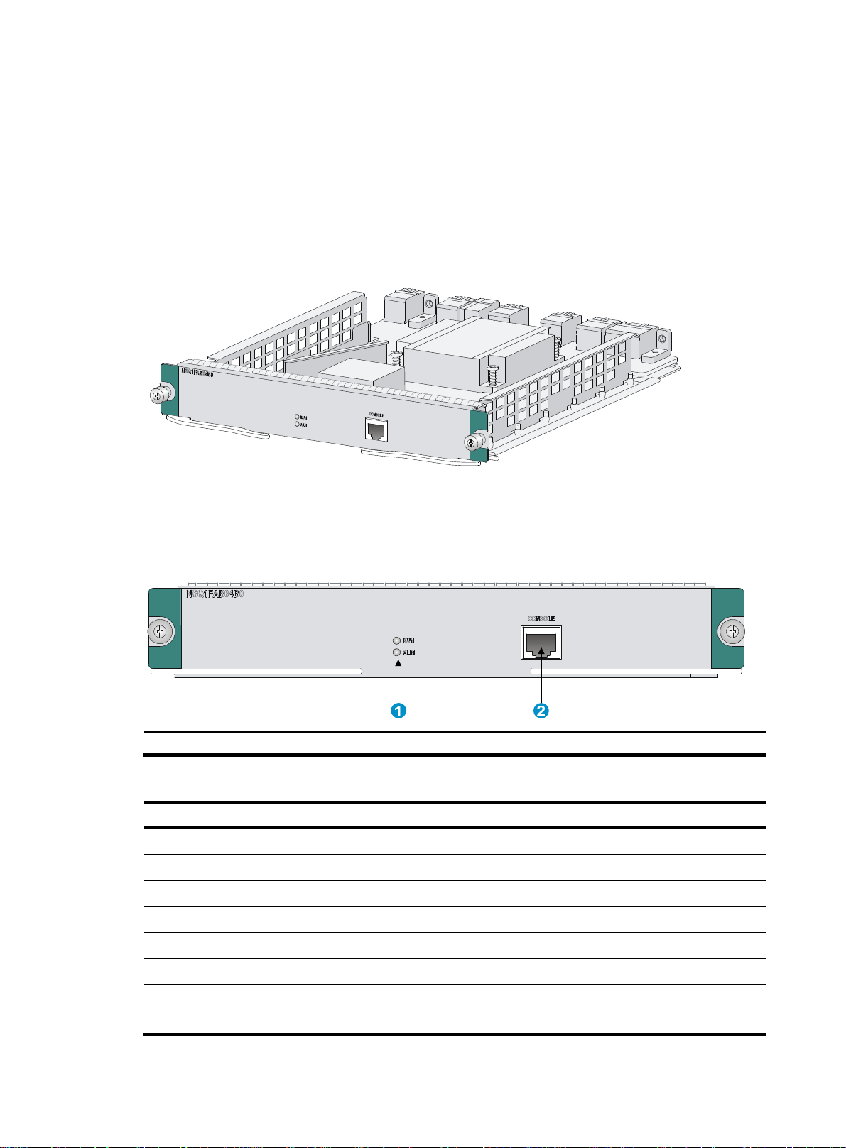
Figure 1 NSQ1FAB04B0 switching fabric module
2 Specifications
Figure 2 Front panel of the NSQ1FAB04B0
(1) Switching fabric module status LED (2) Console port (CONSOLE)
Table 1 Switching fabric module specifications
Item S
Dimensions (H × W × D) 40 × 256 × 298 mm (1.57 × 10.08 × 11.73 in)
Power consumption 48 W to 65 W
Weight 1.71 kg (3.77 lb)
Hot swapping Supported
ecification
Connector type RJ-45
Interfaces 1 console port
Ambient temperature
Operating: 0°C to 45°C (32°F to 113°F)
Storage: –40°C to +70°C (–40°F to +158°F)
i
Page 2

Manual Version: 6PW104-20170414 BOM: 3123A0R3
p
Item Specification
3 LEDs
Ambient humidity
Compatible device model and slot
Operating: 10%RH to 95%RH, noncondensing
Storage: 5%RH to 95%RH, noncondensing
M9006 gateway (slot 6 to slot 9)
T9006 IPS (slot 6 to slot 9)
The NSQ1FAB04B0 provides LEDs to show the operating status of the switching fabric module.
Table 2 LED description
RUN LED ALM LED Descri
Flashing (0.5 Hz) Off The switching fabric module is operating properly.
Off On The switching fabric module is faulty.
Flashing (0.5 Hz) On
Off Off The switching fabric module has not started.
On Off The switching fabric module is up.
The temperature of the switching fabric module has exceeded the
upper or lower limit.
tion
4 Installing and removing the NSQ1FAB04B0
CAUTION:
• Wear a well-grounded ESD-preventive wrist before you install or remove the switching fabric
module.
• Do not touch the surface-mounted components directly with your hands when you install or remove
the switching fabric module.
At least one switching fabric module is required. Install in to either Slot 6 or Slot 7. You can install a
maximum of 4 switching fabric modules on the device.
4.1 Installing the NSQ1FAB04B0
1. Face the rear panel of the device.
2. Identify the slot to install the switching fabric module, and remove the filler panel from the slot.
This manual uses slot 7 as an example.
3. Place the switching fabric module vertically with the surface-mounted components facing left. Pull
outward the ejector levers and gently push the switching fabric module in along the slot guide rails
until the switching fabric module is in close contact with the backplane. (See callout 1 in Figure 3 .)
4. Push the ejector levers inward. (See callout 2 in Figure 3 .)
5. Tighten the captive screws with a Phillips screwdriver to secure the switching fabric module in the
slot. (See callout 3 in Figure 3 .)
ii
Page 3
Manual Version: 6PW104-20170414 BOM: 3123A0R3
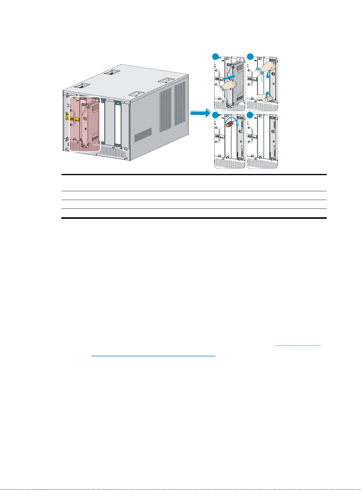
Figure 3 Installing an NSQ1FAB04B0
1
3
2
4
(1) Gently push the switching fabric module in along the slot guide rails until the switching fabric module is in
close contact with the backplane.
(2) Push the ejector levers inward.
(3) Tighten the captive screws with a Phillips screwdriver.
(4) Installation is finished
4.2 Removing the NSQ1FAB04B0
1. Use a Phillips screwdriver to loosen the captive screws at both sides of the switching fabric module
until all pressure is released.
2. Pull the ejector levers at both sides of the switching fabric module outward, and pull the switching
fabric module along the guide rails until it completely comes out of the backplane.
3. Place the switching fabric module on an anti-static workbench with the surface-mounted
components up, or put it in an anti-static bag.
If no new switching fabric module is to be installed, install a filler panel to prevent dust and ensure
good ventilation in the device.
5 Obtaining documentation
To access the most up-to-date H3C product documentation on the H3C website at www.h3c.com.hk:
1. Go to http://www.h3c.com.hk/Technical_Documents.
2. Choose the desired product category and model.
Copyright © 2017 New H3C Technologies Co., Ltd.
iii
 Loading...